آليات الفشل الكيميائي الميكانيكي للأنود السيليكوني في البطاريات الصلبة Chemo-mechanical failure mechanisms of the silicon anode in solid-state batteries
السيليكون هو مادة أنود واعدة بسبب سعتها النظرية العالية، وانخفاض جهد الليثيوم، وانخفاض خطر تشكيل الدندريت. ومع ذلك، فإن الأداء الكهروكيميائي لأنودات السيليكون في البطاريات الصلبة لا يزال ضعيفًا (على سبيل المثال، سعة فعلية منخفضة وتدهور سريع في السعة)، مما يعيق التطبيقات العملية. هنا آليات الفشل الكيميائي الميكانيكي للمركبوتم الكشف عن الأنودات المصنوعة من السيليكون الخالي من الإلكتروليت الصلب من خلال دمج التوصيفات الهيكلية والكيميائية مع المحاكاة النظرية. ينمو الطور الفاصل للإلكتروليت الصلب عندتسبب الواجهة زيادة شديدة في المقاومة في الأنودات المركبة، مما يفسر تدهور سعتها السريع. تظهر الأنودات السيليكونية الخالية من الإلكتروليت الصلب موصلية أيونية وإلكترونية كافية، مما يمكّن من تحقيق سعة نوعية عالية. ومع ذلك، فإن تكوين فراغات على المقياس الميكروي أثناء إزالة الليثيوم يسبب إجهادًا ميكانيكيًا أكبر عند الواجهات ثنائية الأبعاد لهذه الأنودات مقارنةً بالأنودات المركبة. يساعد فهم آليات الفشل الكيميائي الميكانيكي لمعماريات الأنود المختلفة ودور تكوين الواجهة في تقديم إرشادات لتصميم مواد الكهروضوئية المحسّنة.
تظهر البطاريات الحالة الصلبة (SSBs) كأجهزة تخزين طاقة من الجيل التالي ذات كثافة طاقة عالية وسلامة محسّنة.بالمقارنة مع البطاريات التقليدية التي تحتوي على إلكتروليتات سائلة، تلعب الكيمياء الميكانيكية دورًا أكثر بروزًا بسبب الاتصالات الصلبة/الصلبة الصارمة وغالبًا ما تكون الخصائص الميكانيكية لمكونات الخلية مختلفة تمامًا.تظهر الإلكتروليتات الصلبة (SEs) والمواد النشطة خصائص كيميائية وميكانيكية مختلفة، مما يؤدي إلى تفاعلات كيميائية-ميكانيكية معقدة في البطاريات الصلبة (SSBs)، خاصة عند الواجهات.
السيليكون (Si)، الذي يلعب دورًا متزايدًا كمكون للأنود في بطاريات الليثيوم أيون، تم استكشافه مؤخرًا كمادة أنود بديلة واعدة في بطاريات الحالة الصلبة نظرًا لسعته النظرية العالية المماثلة.استنادًا إلىفي درجة حرارة الغرفة) مقارنةً مع معدن الليثيومعملية السبك عند جهد (ضد تجنب نواة معدن الليثيوم ونمو الشجرة البلورية، بالإضافة إلى تحقيق كثافة طاقة أعلى مقارنةً بالأنودات الأخرى من السبائك.علاوة على ذلك، فإن التكلفة المنخفضة والاستقرار الجيد للسيليكون في الهواء تؤهله للتصنيع على نطاق واسع.نظرًا لتأثيرات الحجم الكبير، تظهر أنودات السيليكون تفتت جزيئات السيليكون وتكوين مستمر لطبقة التفاعل الصلبة (SEI) في الإلكتروليتات السائلة، مما يؤدي إلى فقدان شديد في مخزون الليثيوم.على النقيض من ذلك، قد تظهر أنودات السيليكون في بطاريات الحالة الصلبة تشكيلًا أقل أو مختلفًا للطبقة السطحية الصلبة وتفتيت الجسيمات بسبب الصلابة الميكانيكية للكهارل غير العضوية والضغط الخارجي، مما يوفر فرصة لتحقيق استقرار أفضل في الدورة..
ومع ذلك، فإن التغيرات الكبيرة في الحجم في السيليكون أثناء الليثiation/إزالة الليثيوم (أي، لتشكيلمن Si) تشكل تحديًا من منظور الميكانيكا والميكانيكا الكيميائية الأساسية
تظل الآليات غامضة. تواجه الأنودات المصنوعة من السيليكون في البطاريات الصلبة ثلاث قضايا كيميائية ميكانيكية تمثل تحديات خاصة. (1) من المعروف أن السيليكون غير مستقر مع الإلكتروليتات الكبريتية عند جهد الليثيوم المنخفض، مما يؤدي إلى تكوين طبقة من SEI عند واجهة. ومع ذلك، لم يتم الإبلاغ عن الكثير من الأعمال المتعلقة بتعديل سطح جزيئات السيليكون (أي، طبقات الطلاء) حتى الآن. تعاني موصلية الأيونات/الإلكترونات في الأنودات المركبة من السيليكون بشكل خاص من هذه التفاعلات التحليلية. وبالتالي، تتطلب مكونات طبقة الإلكتروليت الصلبة، والهيكل الدقيق لها، ومعدل نموها أثناء الدورة، فهمًا أفضل. (2) بخلاف الأنود المركب الذي يحتوي على واجهة ثلاثية الأبعاد متصلة، يؤدي استخدام أنود السيليكون الخالي من الإلكتروليت الصلب إلى واجهة مسطحة من السيليكون|الإلكتروليت الصلب (المشار إليها فيما بعد بالواجهة ثنائية الأبعاد والمرحلة الانتقالية من أجل البساطة؛ الشكل التكميلي 1 والملاحظة التكملية 1)، مما يتسبب في تدهور أقل لطبقة الإلكتروليت الصلب لكل وحدة كتلة من السيليكون ويقلل من فقدان الليثيوم غير القابل للعكس.. ومع ذلك، فإن السيليكون النقي هو موصل شبه، وزيادة سمك أنودات أفلام السيليكون المرسب إلى أكثر منيسبب نقص في نقل الأيونات/الإلكتروناتتفتقر الموصلية الأيونية/الإلكترونية الجزئية للأنودات المصنوعة من السيليكون الخالي من الإلكتروليت الصلب إلى تحقيقات كمية حتى الآن، خاصة في حالات الشحن المختلفة. يتطلب الأمر توضيح ما إذا كانت إضافات الإلكتروليت الصلب/الكربون الموصل أو نوع معين من التعديل ضرورية لدعم نقل الأيونات/الإلكترونات. (3) من غير المحتمل فقدان الاتصال عند واجهات السيليكون|الإلكتروليت الصلب خلال عمليات الليثiation بسبب التمدد الحجمي للسيليكون، ومع ذلك، فإن ما إذا كانت الواجهات تظل مستقرة خلال عمليات إزالة الليثيوم هو سؤال مفتوح، خاصة بالنسبة للواجهة ثنائية الأبعاد.
يهدف هذا العمل إلى فهم أفضل للتفاعل بين نقل الليثيوم، وتطور الميكروهيكل، وتأثيرات عدم التوافق الميكانيكية المرتبطة عبر الواجهات غير المتجانسة لكشف آليات الفشل لكل من المركب. (LPSCl) وموصلات السيليكون الخالية من الإلكتروليت في البطاريات الصلبة. يتم دراسة مكونات واجهة الإلكتروليت الصلب والميكروهيكل للواجهات من خلال تقنيات تحليل كيميائي وميكروهيكلي متعددة المقاييس (من المقياس الذري إلى مقياس خلية البطارية). يتم استخدام إعداد بطارية ثلاثي الأقطاب لتقييم معدل نمو واجهة الإلكتروليت الصلب بشكل كمي.كشفت الشوائب السطحية لجزيئات السيليكون أنها تشارك في تشكيل طبقة الإلكتروليت الصلبة، مما يسبب مسارات تدهور معقدة. تحليل مختلفتظهر هياكل السبائك موصلية أيونية/إلكترونية كافية للأنودات السيليكونية الخالية من الإلكتروليت الصلب، مما يشير إلى أن الإضافات الأيونية/الإلكترونية ليست مطلوبة. الأنودات السيليكونية الخالية من الإلكتروليت الصلب، دون مكونات عازلة إلكترونيًا موزعة (أي LPSCl و SEI)، تظهر سعة نوعية أعلى حتى منالأنودات المركبة. ومع ذلك، تكشف تحقيقات المجهر الإلكتروني الماسح (SEM) جنبًا إلى جنب مع نماذج كيميائية ميكانيكية لكسور الحقل الطوري عن إجهاد رئيسي أقصى مرتفع (-0.3 إلى 0.8 جيجا باسكال) وزيادة في التشوه البلاستيكي بنسبة 10% عند واجهة Si|LPSCl ثنائية الأبعاد، مما يؤدي إلىتكوين الفراغ عند واجهة Si|LPSCI ثنائية الأبعاد بعد أول إزالة ليثيوم وانخفاض السعة السريع للبطاريات الصلبة القائمة على أنودات السيليكون الخالية من الإلكتروليت.
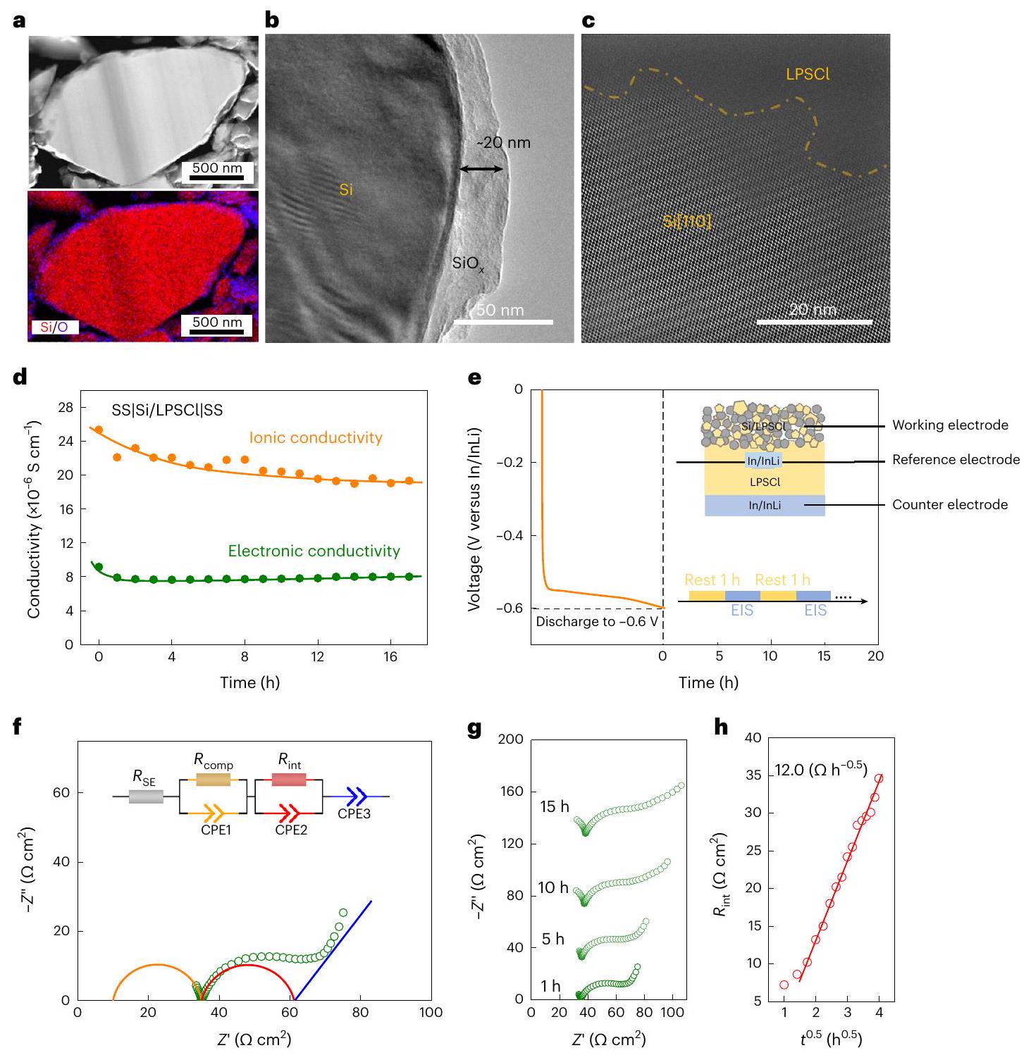
لتقييم الاستقرار الكيميائي لأقطاب Si/LPSCl المركبة، تم خلط LPSCl مع جزيئات خشنة (LPSCl (خشنة)) مع مسحوق Si (نسبة وزن Si/LPSCl 1/1، مما يتوافق مع نسبة حجم 0.68:1.00) في هاون لمدة 30 دقيقة. توفر الأشكال التكميلية 2 و 3 معلومات أساسية عن Si و LPSCl المستخدمين هنا. يتم ملاحظة الأكسجين كشوائب على سطح جزيئات Si، كما يتضح من مجهر الإلكترون الناقل (STEM) بتقنية الحقل المظلم الحلقي عالي الزاوية (HAADF)، مما يظهرعلى سطح الجسيم (الشكل 1أ). سمك الـطبقة هي (الشكل 1ب) .
تظهر صورة STEM المفلترة بواسطة طرح الخلفية المتوسطة (الشكل 1c) أنه لم تتشكل أي مراحل بلورية جديدة عند واجهة Si|LPSCl، مما يشير إلى واجهة مستقرة كيميائيًا من خلال الاتصال المباشر، على الرغم من أنه لا يمكن استبعاد الطبقات غير المتبلورة تمامًا (الشكل 1c). نفترض أنويمكن أن تتفاعل LPSCI كيميائيًا على النانو، ومع ذلك لا توجد أدلة واضحة على تكوين منتجات تفاعل قبل الليثiation للسيليكون (الشكل التكميلي 4). لمزيد من التحقيق في استقرار مركبات Si/LPSCI النقية وأيون/إلكترون تم تطبيق النقل عبر الطيف الترددي الكهربائي المعتمد على الزمن (EIS) على أساس إعداد خلية من الفولاذ المقاوم للصدأ SS|Si/LPSCI|SS (قياس واحد كل ساعة) (الشكل التوضيحي التكميلي 5a). تم استخدام نموذج خط النقل لتناسب المقاومات وتقسيم المساهمات الأيونية والإلكترونية في المزيج.مركب (الشكل التوضيحي التكميلي 5ب والجدول التكميلي 1)الموصلية الأيونيةمن المركبينخفض منإلىبعد 17 ساعة، في حين أن الموصلية الكهربائيةيبقى مستقراً نسبياً عندبعد 17 ساعة. يظهر انتشار العناصر الواجهة تأثيرًا أكبر على الموصلية الأيونية مقارنةً بالموصلية الإلكترونية للمركب. (الشكل 1د).
لدراسة الاستقرار الكهروكيميائي عند واجهة Si|LPSCl، تم ترك خلايا In/InLi|LPSCI|Si/LPSCI عند جهد الدائرة المفتوحة لـبعد أن تم تسريحه إلىأي، إلى مقابل الشكل 1f يوضح إجراء القياس، حيث تم إجراء قياسات EIS كل ساعة. تم استخدام قطب مرجعي In/InLi (RE) لفصل مقاومة الكاثود (أي، المركب) من إجمالي مقاومة الخلية بأكملهاتظهر الشكل التوضيحي الإضافي 6 إعداد RE In/InLi. يوضح الشكل 1f طيف EIS الأولي (القطب العامل مقابل RE) والدائرة المعادلة الملائمة بعد تفريغ البطارية إلى (ضد ). تم استخدام نموذج مبسط لتناسب طيف EIS (الملاحظة التكميلية 2 والشكل التكميلية 7). المقاومة فوق يتوافق مع نقل الأيونات (‘انخفاض الجهد’) في الفاصل SE ( ) و مركب الأقطاب ( )، في حين أن المقاومة في النطاق من إلى 0.5 هرتز يُعزى بشكل رئيسي إلى المساهمة في واجهة LPSCl ( ) (المرجع 22). تُظهر مخططات المعاوقة الموضحة في الشكل 1 ج بوضوح أن يزداد تدريجياً أثناء الراحة عند الحد الأقصى لإمكانات الليثيوم الكيميائية، مما يشير إلى عدم استقرار الواجهة. أيضاً،يزداد خطيًا مع الجذر التربيعي لوقت الراحة (كما هو موضح في نموذج من نوع فاغنر للتفاعلات الصلبة التي تتحكم فيها الانتشار (الشكل 1h والجدول التكميلي 2)المنحدرالذي يتوافق مع معدل نمو SEI عند واجهة Si|LPSCl، تم حسابه ليكونفي و تظهر حسابات نظرية الكثافة (DFT) أن طاقة الربط لـأكبر بكثير من ذلك لـ (-7.21 eV مقابل -0.79 eV )، مما يشير إلى تفاعل أقوى بين الليثيوم و LPSCI (الشكل التكميلي 8). تشير هذه المقارنة البسيطة إلى أن LPSCI يتم اختزاله من خلال التفاعل مع الليثيوم من سبائك عند الجهود المنخفضة، مما يؤدي إلى تشكيل طبقة SEI وتدهورها عندواجهة LPSCl.
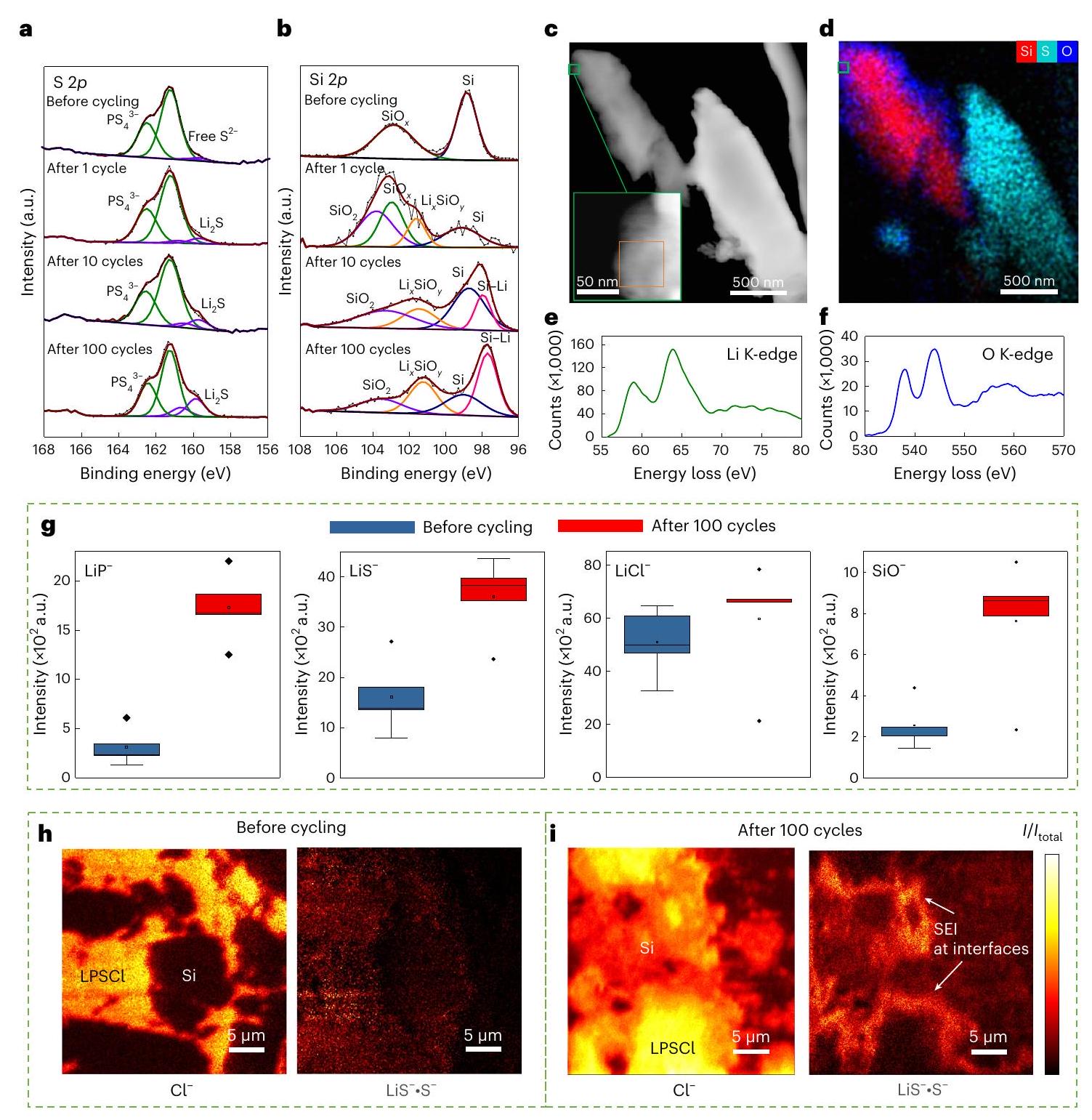
لتحقيق في منتجات التحلل الكهروكيميائي عندتم إجراء قياسات طيف الإلكترون السيني (XPS) قبل وبعد 1 و 10 و 100 دورة لخلية In/InLi|LPSCl|Si/LPSCI. القمم المزدوجة القوية عند 161.7 eV والقمم المزدوجة الصغيرة جدًا عند 160.1 eV فيالطيف قبل ركوب الدراجات ينشأ منأربعة أوجه و ‘حر’أيونات هيكل الأرجيروديت LPSCI، على التوالي (الشكل 2أ)زيادة شدة القمتين المزدوجتين عند 160.1 إلكترون فولت فييحدث الطيف بعد دورة واحدة، والتي تتوافق مع القادمة من تحلل LPSCl مع الليثيوم. شدة زيادة أخرى خلال الدورات التالية، مما يشير إلى النمو المستمر للـ SEI. يجب الإشارة هنا إلى أن الـالشوائب على سطح السيليكون تشارك أيضًا في تكوين طبقة العزل الصلبة. القمم عند و فيالطيف قبل الدورة يأتي من السيليكون وعلى التوالي (الشكل 2ب) ( ) و تُلاحظ بعد دورة واحدة بسبب التفاعل بينوالليثيومنفترض أن التباين في النسبوفقًا للتفاعليتم دفع السيليكون بواسطة الليثيوم المتكون، وبالتالي، يتشكل على ما يبدو مع المرحلة. تُظهر الصورة 2c صورة HAADF cryo-STEM لجزيئات السيليكون وLPSCI في اتصال مع بعضها البعض بعد 100 دورة. الصورة 2d هي خريطة التحليل الطيفي بالأشعة السينية المشتتة للطاقة (EDS) المقابلة التي تُظهر توزيعات العناصر. تُظهر هياكل حافة K في طيف فقدان الطاقة الإلكترونية (EELS) لـ
الشكل 1 | الاستقرار (الكيميائي) الكهربائي لأقطاب Si/LPSCI المركبة. أ، صورة HAADF-STEM لجزيئات السيليكون وخريطة EDS المقابلة. ب، صورة TEM لجزيء سيليكون. ج، صورة HAADF-STEM مع تصفية متوسط الخلفية عند واجهة Si|LPSCl. د، الموصلية الإلكترونية والأيونية للمزيج الجديد.كوظيفة للزمن. هـ، إجراء الراحة والمقاومة
القياسات المستندة إلى خلية ثلاثية الأقطاب. يوضح الشكل الفرعي إعداد خلية الثلاثة أقطاب. f، رسم نايكويست والدائرة المعادلة المقابلة المستخدمة لتقييم بيانات المقاومة (القطب العامل مقابل القطب المرجعي).رسوم نيكيست لخلية نموذجية في حالة الراحة على المدى الطويل.كنتيجة لجذر الزمن. يتوافق الليثيوم جيدًا مع طيف تشتت الأشعة السينية غير المرنة المحاكى والتجريبي لليثيوم في (الشكل 2e) . ومع ذلك، فإن القمة السابقة والقمة K لعناصر الأكسجين (الشكل 2f) قد انتقلت إلى قيم أعلى ( و ، على التوالي) مقارنةً مع بيانات تشتت الأشعة السينية غير المرنة المحاكاة والتجريبية المقابلة ( و على التوالي. بالإضافة إلى ذلك، فإن نسبة شدة الذروة قبل الذروة إلى ذروة K للأكسجين (الشكل 2f) أقل قليلاً من النسب المحاكاة والتجريبية المقابلة في بيانات تشتت الأشعة السينية غير المرنة. قد تنشأ الفروق الصغيرة في هيكلي الذروة قبل الذروة وذروة K للأكسجين من وجودفي. بالإضافة إلى ذلك، فإن الليثيوم غير القابل للعكس بعد 10 دورات يؤدي إلى تكوين ذروة عندفيطيف (الشكل 2ب). لاحظ أن إشارة XPS لكمية صغيرة منبعد دورة واحدة قد يتم دفنها بواسطة طبقة SEI.
تم استخدام مطيافية الكتلة للأيونات الثانوية بتقنية زمن الطيران (ToF-SIMS) لتأكيد التحلل المحلي لالكتروليت LPSCI في الأنود المركب بعد الدورات. أظهر تحليل سطح المركب بعد 100 دورة (الشكل 2g) زيادة في وشدة الإشارات. يمكن أن تُنسب هذه الإشارات إلى منتجات التحلل الواجهة لـ LPSCI (أي،وكلوريد الليثيوم. بالإضافة إلى ذلك، زيادة في الـتمت ملاحظة شدة الإشارة بعد 100 دورة. وجوديمكن أن تعزز الأيونات التأين لـشظايا، مما يؤدي إلى ارتفاعشدة الإشارة، التي نعتبرها تأكيدًا لنتائج XPS، مما يشير إلى تكوين و الشكل 2 هـ، و يُظهر صور الكتلة لـ ToF-SIMS لجزيئات السيليكون في مصفوفة LPSCI قبل الدورة وبعد 100 دورة، على التوالي. بشكل خاص، بعد الدورة، وُجدت طبقة ذات كثافة أعلى من شظايا الكبريت حول جزيئات السيليكون. نحن نفسر هذا كدليل واضح على الـ-SEI الغني فيواجهة LPSCl. تلخيص النتائج التي تم الحصول عليها من تقنيات التوصيف المختلفة، يحدث التحلل الكهروكيميائي عندواجهة LPSCl (بما في ذلك “) ومكونات طبقة SEI من المحتمل أن تشمل نواتج تحلل LPSCI (أي، و LiCl )، بالإضافة إلى -مكونات SEI المشتقة (أي، و ).
الشكل 2 | توصيف مكونات SEI عند واجهات Si|LPSCI. أ، ب، S2 (أ) و Si2 (ب) طيف XPS لـ Si|LPSCI قبل الدورة وبعد دورات مختلفة. ج، صورة HAADF cryo-STEM (ج) ورسم خرائط EDS المقابل (د) لـ Si/LPSCI بعد 100 دورة. هـ، و، طيف EELS لحافة Li K (هـ) وحافة O K (و) لـ Si/LPSCl بعد 100 دورة. تحتوي الصندوق البرتقالي في الزاوية في ج على المنطقة التي تم الحصول منها على أطياف EELS. ز، مخططات الصندوق لشدات الإشارة المتعلقة بـ SEI (أي، ، و) من تحليلات سطح ToF-SIMS لـقبل وبعد 100 دورة. تم تطبيع شدة الإشارات المتعلقة بـ SEI بواسطة Sإشارة
الشدة. الخطوط في الصناديق تمثل الوسيط، والحدود السفلية والعلوية للصندوق تشير إلى النسب المئوية 25 و75، على التوالي. تمتد الشعيرات إلىنطاق الربيع الداخلي، والنقاط هي نقاط شاذة.صور ToF-SIMS لـشظية، ومنتج الـوشظايا فيمركبات LPSCl قبل الدورة (h) وبعد 100 دورة (i). تم تطبيع جميع شدة الإشارات بواسطة إجمالي شدة الإشارة. HAADF cryo-STEM، HAADF-STEM تعمل تحت ظروف التبريد.
نقل الأيونات/الإلكترونات في أنودات السيليكون الخالية من الإلكتروليت
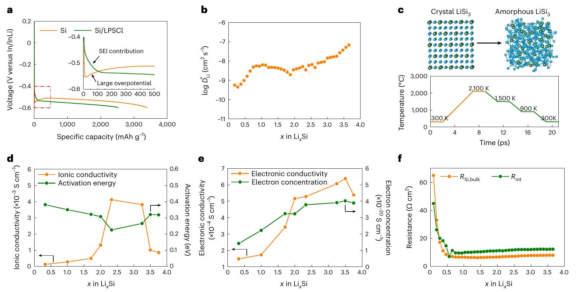
لتجنب التأثير الضار لتدهور الواجهة في المركبالأنودات أثناء الدورة، أنودات السيليكون الخالية من الإلكتروليت الصلب (أي، تم تصنيع روابط من فلوريد البولي فينيليدين، مما يتيح واجهة ثنائية الأبعاد Si|LPSCl مع تقليل تكوين SEI لكل وحدة كتلة من Si. تم تدوير خلايا In/InLi|LPSCl|Si/LPSCl و In/InLi|LPSCl|Si عند 0.1C لمقارنة السعة النوعية لمركبات Si/LPSCI والأنودات الخالية من SE. على الرغم من ملاحظة فرق جهد كبير خلال عملية الليثiation الأولية، إلا أن الأنود الخالي من SE يظهر انخفاضًا تدريجيًا في فرق الجهد خلال عمليات الليثiation التالية، مما يوفر سعة نوعية قدرها (الشكل 3أ). بالمقابل، يظهر القطب السالب Si/LPSCl سعة نوعية منخفضة نسبياً من بما في ذلك السعة الإضافية ( ) من تشكيل SEI. هذه تشير النتائج إلى أن الأنود المصنوع من السيليكون الخالي من الإلكتروليت الصلب يظهر موصلية مختلطة كافية بمجرد إدخال كمية صغيرة من الليثيوم. تحسين الـتظهر النسب في الأنودات المركبة من السيليكون تأثيرات قليلة على تحسين السعة النوعية (الشكل التكميلي 9).
لقياس نقل الأيونات/الإلكترونات في أنود السيليكون الخالي من الإلكتروليت عند حالات الشحن المختلفة، معامل الانتشار الكيميائي الليثيوم (الظاهر)تم قياسه بواسطة تقنية المعايرة المتقطعة الجلفانية (GITT)المقاسيؤكد تحسين حركية انتشار الليثيوم مع زيادة تركيز الليثيوم. نقوم بتقييمعند مستوى شحن منخفض، وزاد معامل الانتشار بمقدار مرتينفي الحالة المشبعة بالكامل بالليثيوم (الشكل 3ب). المتوسط من أنودات السيليكون الخالية من السيلينيوم ( أكبر بمقدار مرتبتين من حيث الحجم من ذلك
الشكل 3 | نقل الأيونات/الإلكترونات في أنودات السيليكون الخالية من الإلكتروليت الصلب. أ، منحنيات الليثيوم لأنودات السيليكون الخالية من الإلكتروليت الصلب والسيليكون/ LPSCl عند 0.1C. ب، معامل انتشار الليثيوم الكيميائي لـسبائك لمختلف أنظمة على رقاقة. ك، بلورات محاكاة وغير متبلورةالهياكل قبل وبعد عملية الذوبان والتبريد السريع. د، الأيونات المحاكاة التوصيلية وطاقة التنشيط المقابلة للمواد غير المتبلورةسبائك لمختلف أنظمة على رقاقة عند 300 كلفن. e، الموصلية الإلكترونية المحاكاة وتركيز الإلكترونات المقابل للمواد غير المتبلورةسبائك لمختلف أنظمة على شريحة (SoCs) عند 300 كلفن، تغييرات المقاومة في الأنود السيليكوني خلال عملية الليثiation. منمواد الكاثود المبلغ عنها في الأدبياتمما يشير إلى أن الإضافات الأيونية/الإلكترونية ليست ضرورية لقطب السيليكون.
التوصيلات الأيونية/الإلكترونية الجزئية لـتم حسابها خلال عملية الليثيوم بناءً على محاكاة DFT لدعم السعة النوعية العالية لأقطاب السيليكون الخالية من SE. الهياكل البلورية لـتم الحصول على السبائك من قاعدة بيانات مشروع المواد، بما في ذلك، و (الجدول التكميلي 3). نظرًا لأن عملية الليثيوم الكهربائي تحول مراحل السيليكون البلورية الأصلية إلى غير متبلورة (المراجع 30، 31)، تم تطبيق عملية الذوبان والتبريد للحصول على هياكل غير متبلورة لهذه سبائك (الشكل 3ج). دالة التوزيع الشعاعي لمختلفالسبائك توضح بوضوح أنه لا يوجد قمة حادة للجيران الثانويين، مما يؤكد الطبيعة غير المتبلورة (نقص النظام بعيد المدى) لـسبائك (الشكل التوضيحي 10).
التوصيلية الأيونية لـ هو تزداد الموصلية الأيونية أكثر إلىأثناء الليثيومإلى، ثم ينخفض تدريجياً إلى للتليث التالي إلى (الشكل 3د). التغير في طاقة التنشيط المحسوبة من الإزاحة المتوسطة المربعة المعتمدة على درجة الحرارة يظهر الاتجاه المعاكس (الشكل التكميلي 11). الزيادة تحسن التركيز من الموصلية الأيونية. عند تركيز منخفض من الليثيوم، فإنتجد الأيونات مواقع شاغرة كافية للانتشار السريعمرتفع بشكل مفرطالتركيز يؤدي إلى نقص في الشواغر لـالهجرة، مما يقلل من النفاذية الأيونية والتوصيلية لـ (مرجع 33). لذلك، فإن تركيز (أي، يؤدي إلى أعلى موصلية أيونية لـمع أدنى طاقة تنشيط تبلغ 0.225 إلكترون فولت (الجدول التكميلي 4). بالتوازي، يؤدي تركيز الإلكترونات العالي عمومًا إلى موصلية إلكترونية عالية. الشكل 3e يوضح الموصلية الإلكترونيةزيادة منإلىبسبب الزيادة تركيز الإلكترونات منإلىعلى التوالي (الجدول التكميلي 4).يظهر تركيزًا أقل قليلاً من الإلكترونات وبالتالي موصلية إلكترونية أقل قليلاً (أي، ). لاحظ أن الموصلية الأيونية/الإلكترونية المحاكية المستندة فقط إلى ميزات الهيكل الكتلي قد تختلف عن النتائج التجريبية، التي تتأثر بالشوائب وحدود الحبيبات وغيرها من العيوب الميكروهيكلية. على الرغم من أن الأنواع المختلفة لم يتم بعد تخليق ودراسة السبائك فيما يتعلق بموصلية الأيونات/الإلكترونات، والبيانات النظرية المستخلصة متوافقة مع التجريبية.القيم في نطاقات الخطأ المعتادة (الملاحظة التكميلية 3). في أي حال، فإن المتوسطات الحسابية للتوصيلية الأيونية ( ) وموصلية كهربائية ( استنادًا إلى محاكاة DFT، تؤكد الموصلية الأيونية/الإلكترونية الكافية لأقطاب السيليكون المLithيوم الخالية من SE دون إضافات إضافية، مما يمكّن من أداء جيد عند السرعات العالية (الشكل التكميلي 12).
تم إجراء قياسات المقاومة خلال كل استرخاء للجهد في قياس GITT لتقييمالنقل عبر واجهة Si|LPSCI ثنائية الأبعاد (الشكل التكميلي 13 والجدول التكميلي 5). على الرغم من أن الموصلية الأيونية/الإلكترونية تتغير باستمرار أثناء الاسترخاء، فإن مقاومة كتلة السيليكون ( ) أولاً ينخفض من 64.9 إلى بعد الليثيومثم يبقى عند قيمة منخفضة ( ) للتLithiation التالي (الشكل 3f). المنخفض يتماشى مع الموصلية الأيونية/الإلكترونية العالية ويمكّن من النقل السريع لليثيوم في الأنود السيليكوني الخالي من SE (الشكل 3f). مقاومة الواجهةتنخفض من 44.9 إلىبعد الليثيوم إلىبسبب تحسين ديناميكيات الواجهة ثم يزيد قليلاً إلىبعد الليثiation الكامل بسبب تشكيل SEI ثنائي الأبعاد. بالإضافة إلى ذلك، تم قياس المقاومات المعتمدة على الزمن أثناء الراحة عند جهد الدائرة المفتوحة بعد الليثiation الكامل. الثابت المعدل المحسوب هو، وهو ما هو أقل بكثير من ذلك لـ الأنود (أي، ) (الشكل التوضيحي 14 والجدول التوضيحي 6). على افتراض أن حركية نمو SEI لا تعتمد على
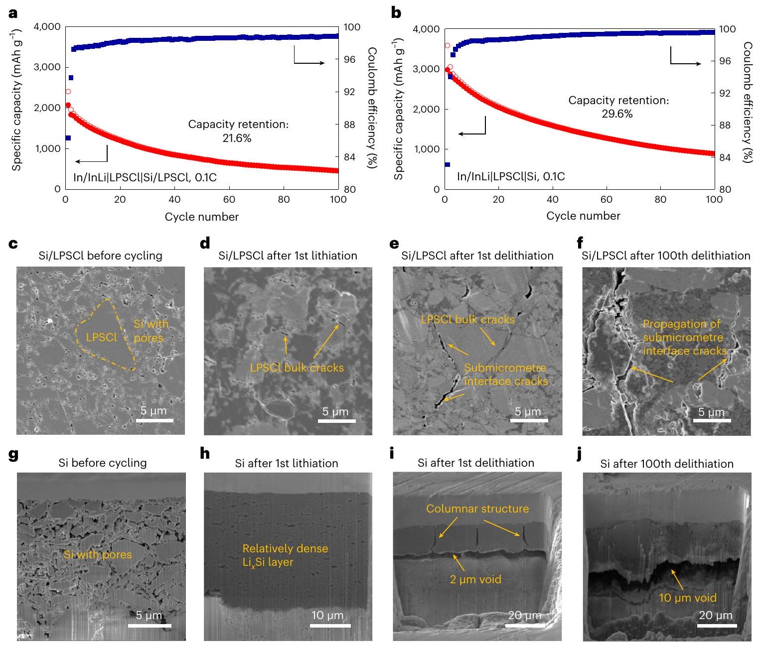
الشكل 4 | استقرار الدورة عند واجهات Si|LPSCl ثنائية وثلاثية الأبعاد. أ، ب، أداء الدورة لخلية In/InLi|LPSCl|Si/LPSCl (أ) وخلية In/InLi|LPSCI|Si (ب) عند 0.1 C تحت ضغط 50 ميغاباسكال. ج-و، صور SEM مقطعية للأنود Si/LPSCl قبل الدورة (ج)، بعد الليثيوم الأول (د)، بعد إزالة الليثيوم الأول (هـ) و
بعد عملية إزالة الليثيوم المئة (ف). ج-ي، صور SEM مقطعية للأنود السيليكوني الخالي من الإلكتروليت قبل الدورة (ج)، بعد عملية الليثيوم الأولى (ح)، بعد عملية إزالة الليثيوم الأولى (ط) وبعد عملية إزالة الليثيوم المئة (ي). تشير هذه النتيجة، بالنظر إلى هندسة سطح السيليكون، إلى أن نمو طبقة SEI عند واجهة Si|LPSCl ثلاثية الأبعاد يساهم بشكل كبير في زيادة التعقيد في مركب Si/LPSCI.
استقرار الدراجات عند واجهات Si|LPSCI ثنائية وثلاثية الأبعاد
تمت دورة خلايا In/InLi|LPSCI|Si/LPSCI و In/InLi|LPSCI|Si عند 0.1 C تحت ضغط 50 ميغاباسكال للتحقيق في استقرار الدورة على المدى الطويل. احتفاظ السعة لخلايا In/LiIn|LPSCI|Si/LPSCI هو 21.9% بعد 100 دورة (الشكل 4a). يأتي ضعف استقرار الدورة من النمو المستمر لطبقة SEI ثلاثية الأبعاد في Si/LPSCI المركب، كما تم الكشف عنه في المناقشة أعلاه (الشكل 2). يؤدي المضاف من ألياف الكربون المزروعة بالبخار (VGCF) القابلة للتوصيل الإلكتروني إلى تدهور SEI أكثر حدة، حيث أن الكربون له نفس الجهد مثل السيليكون، مما يسبب استقرار دورة أسوأ لقطب Si/LPSCI/VGCF المركب (الشكل التكميلي 15). تظهر أقطاب Si الخالية من SE مع هندستها الطبقية البسيطة تدهورًا أقل في الواجهة لكل حجم من SE وتحتاج الأيونات فقط إلى المرور عبر طبقة SEI ثنائية الأبعاد، مما يتسبب في تقليل الجهد الزائد عند الأنود.ومع ذلك، فإن احتفاظ السعة لخلية In/Liln|LPSCl|Si هو فقط 29.3% بعد 100 دورة (الشكل 4b) تحت الظروف التجريبية المعطاة. لفهم الاستقرار الدوري الضعيف لأقطاب السيليكون الخالية من الإلكتروليت الصلب، يتم مقارنة تطور الميكروستركشر لمركبات Si/LPSCI وأقطاب السيليكون الخالية من الإلكتروليت الصلب في ما يلي.
تمت ملاحظة جزيئات LPSCI والمناطق المسامية لجزيئات السيليكون المجمعة في أنود Si/LPSCl قبل الدورة (الشكل 4c). هذه المناطق من جزيئات السيليكون ذات صلابة عالية منلا يمكن تكثيفه عند 380 ميغاباسكال أثناء التصنيعبينما يسمح LPSCI الناعم نسبيًا بالاتصال الوثيق مع جزيئات السيليكون بعد الضغط تحت 380 ميجا باسكال. يُظهر دمج الليثيوم في السيليكون تأثير تليين مرن، مما يقلل من صلابة السيليكون المليء بالكامل بالليثيوم.إلى 1.5 غيغاباسكال (المراجع 35، 36). يميل تمدد السيليكون تحت ضغط مقيد قدره 50 ميغاباسكال إلى تكثيف البنية المجهرية للمواد اللينة نسبيًا.، مما يؤدي إلى ترابطالميكروهيكل بعد الليثيوم الأول (الشكل 4د). على الرغم من أن الثلاثي الأبعادتظل الواجهات سليمة، لكن الضغط الناتج عن تمدد السيليكون يتسبب في تكوين شقوق داخل جزيئات LPSCl الكتلية (الشكل 4d والشكل التكميلي 16a). تُلاحظ شقوق دون الميكرومتر عند واجهات Si|LPSCl ثلاثية الأبعاد بعد أول عملية إزالة الليثيوم بسبب انكماش السيليكون (الشكل 4e). تنتشر هذه الشقوق دون الميكرومتر وتتسع بعد العملية العاشرة والمئة لإزالة الليثيوم (الشكل التكميلي 16b والشكل 4f). نلاحظ أن واجهة LPSCI|Si/LPSCl تحافظ على اتصال وثيق حتى بعد 100 دورة (الشكل التكميلي 16c).
يظهر الأنود المصنوع من السيليكون الخالي من السيلكون (SE) جزيئات سيليكون منفصلة مع العديد من الفراغات قبل الدورة بسبب شكل وصلابة جزيئات السيليكون (الشكل 4g). السماكة هيوتم حساب المسامية لتكوناستنادًا إلى الكثافة النظرية لـ (المراجع 17، 34). إن توسيع السيليكون لا يضمن فقط اتصالًا جيدًا بين واجهة Si|LPSCl ثنائية الأبعاد، بل يعمل أيضًا على تكثيف طبقة السيليكون. كثيفة ومترابطةيلاحظ وجود بنية دقيقة مع مسامية أقل بكثير بعد الليثيوم الأول، حيث اختفت معظم الفراغات (الشكل 4h). تظهر طبقة السيليكون بنية عمودية بعد عملية إزالة الليثيوم الأولى (الشكل 4i والشكل التكميلي 17a). لا تعود إلى البنية الدقيقة المتجانسة الأصلية عند إزالة الليثيوم، مما يدل على تشوه بلاستيكي لا رجعة فيه. يختلف عن الشقوق تحت الميكرومتر عند واجهات المركب ثلاثي الأبعاد Si/LPSCI،يلاحظ وجود فراغ واسع عند واجهة Si|LPSCI ثنائية الأبعاد (الشكل 4i). زيادة في سمك الفراغيلاحظ بعد عملية التفريغ المئة، مما يدل على شيخوخة خطيرة وتدهور ميكانيكي للثنائي الأبعادواجهة خلال التكرار المتكرر (الشكل التكميلي 17 ب والشكل 4 ج). تعكس طيفيات EIS ذلك من خلال الزيادة، مما يؤكد أن فقدان الاتصال يسبب ضعف استقرار الدورة للأنودات المصنوعة من السيليكون الخالي من SE (الشكل التكميلي 18 والجدول التكميلي 7). لاحظ أن طبقة SEI المتكونة غير مستقرة أيضًا، مما يؤدي إلى فقدان الاتصال من الأنود السيليكوني الخالي من SE بعد أول عملية إزالة الليثيوم (الشكل التكميلي 19). تم تطوير نموذج كسر ميداني مرحلي كيميائي ميكانيكي متكامل لتقييم الإجهاد وتكوين الفراغات عند الواجهات ثنائية وثلاثية الأبعاد خلال عمليات الليثيوم الأولى وإزالة الليثيوم (الملاحظة التكملية 4 والأشكال التكملية 20 و21).
أنودات السيليكون الخالية من السيليكون في خلايا كاملة Si|LPSCI|NCM@LBO
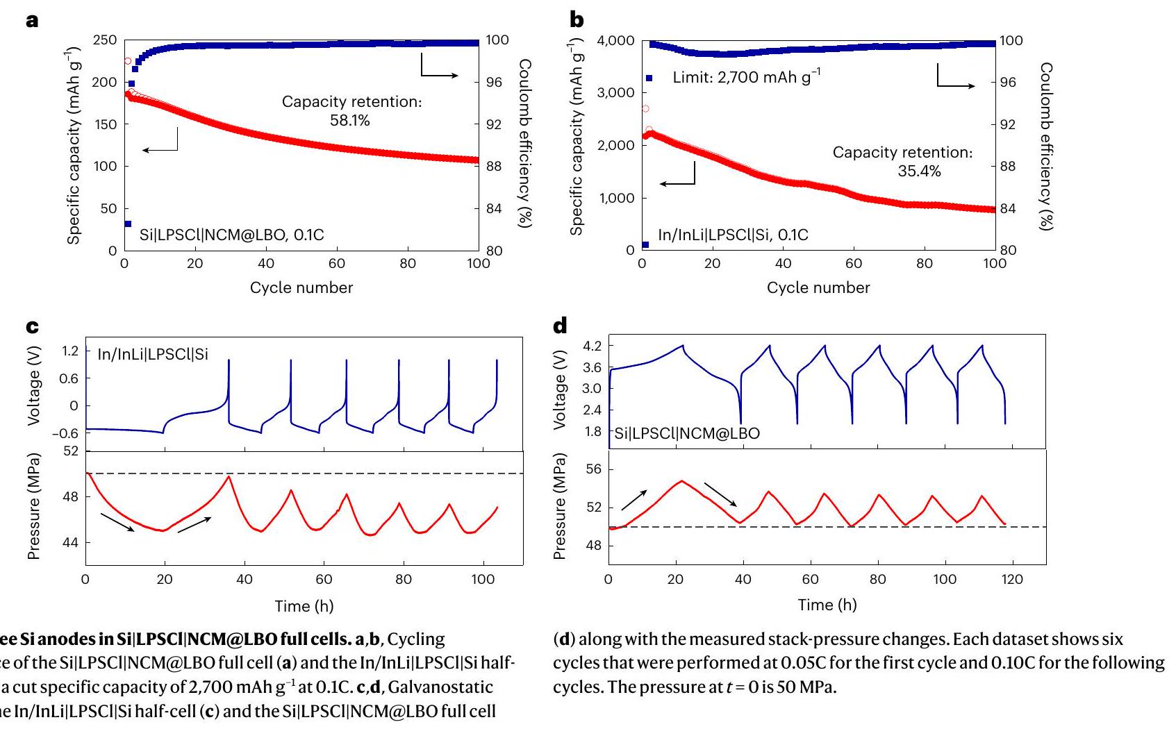
مركبتمت مزامنة الكاثودات (NCM) مع أنودات ورقية من السيليكون خالية من الإلكتروليت بنسبة N/P تبلغ 1.3 في خلايا كاملة. تم طلاء أسطح جزيئات NCM بطبقة رقيقة (2 نانومتر) من (LBO) لمنع التدهور الكهروكيميائي عند واجهة NCM|LPSCI. كانت السعة المساحية للقطب السالب NCM ، والذي يتوافق مع سمك (الشكل التوضيحي 22أ). لاحظنا تأثيرًا كبيرًا للميكروستركشر على أداء الكاثودات NCM السميكة نسبيًا. تظهر كاثودات NCM ذات حجم الجسيمات الصغيرة من LPSCI (NCM@LBO (صغير)) أداءً أفضل من تلك التي تحتوي على LPSCI خشن (NCM@LBO (خشن)) بسبب تحسين تجانس الميكروستركشر (الشكل التوضيحي 22). على الرغم من أن كريات SE المصنوعة من LPSCI (صغير) تظهر مستوى أدنى من موصلية أيونية أفضل من تلك التي تم إعدادها بواسطة LPSCI (خشن)، حيث يتم ملاحظة توزيع متجانس لجزيئات NCM في مصفوفة LPSCI في NCM@LBO (صغير)، مما يفيد في نقل الأيونات/الإلكترونات بسرعة (الأشكال التكميلية 22 و23). تقدم خلايا Si|LPSCI|NCM@LBO (صغير) سعة تفريغ محددة أولية قدرهاويمكنه تشغيل 100 دورة بنجاح مع احتفاظ بسعة بنسبة 58.1% (الشكل 5أ).
تظهر خلايا SSB الكاملة عادة أداءً أسوأ في الدورة مقارنةً بالخلايا نصفية الخلايا مع أنود من الليثيوم المعدني بسبب الفقد السريع لتوازن الليثيوم المدفوع بالسعات غير القابلة للعكس في كل من الأنود والكاثود. تظهر خلايا Si|LPSCI|NCM@LBO الكاملة احتفاظًا أفضل بالسعة مقارنةً بخلايا In/InLi|LPSCI|Si نصفية الخلايا بعد 100 دورة عند 0.1C (58.1% مقابل 29.6%). لتبرير ذلك، تحققنا أولاً مما إذا كان هذا ناتجًا عن عدم اكتمال الليثيوم في الخلايا الكاملة بسبب نسبة N/P البالغة 1.3 (المرجع 37). تم تدوير خلايا In/InLi|LPSCI|Si عند 0.1 C مع قطع عند سعة محددة من (وهو نفس درجة الليثيوم في الخلايا الكاملة) للمقارنة. كانت احتفاظ السعة بعد 100 دورة، مما يشير إلى أن تحسين استقرار الدورة للخلايا الكاملة لا يأتي أساسًا من الليثيوم الجزئي (الشكل 5ب). في الخطوة التالية، تم التحقيق في تطور ضغط الكومة أثناء الدورة الجلفانية. كان الضغط الأصلي 50 ميغاباسكال. إن/إنLiتظهر الخلية تغيرًا في الضغط السلبي (أي، ) أثناء ركوب الدراجات، مما يشير إلى أن تغير الحجم في In/InLi أكبر فعليًا من ذلك في قطب الإلكترود Si الخالي من SE (الشكل 5c). نحن نفترض أن تغير الضغط الإيجابي (أي، يساعد (Si|LPSCI|NCM@ LBO) في الحفاظ على استقرار الدورة للخلايا الكاملة (الشكل 5d). بالإضافة إلى ذلك، يظهر الأنود المركب Si/LPSCI في خلية Si/LPSCI|LPSCI|NCM@ LBO أيضًا تغييرًا إيجابيًا في الضغط (الشكل التكميلية 24). نلاحظ أن الخلايا نصفية قد لا تكون خيارًا جيدًا للتقييم الأولي للقطب الكهربائي الجديد تحت ظروف ضغط محصورة، حيث يمكن أن تتداخل الكيمياء الميكانيكية بشكل خطير وتؤدي إلى سلوكيات مختلفة للخلايا الكاملة.
تمت ملاحظة فقدان الاتصال عند واجهة Si|LPSCI ثنائية الأبعاد أيضًا في الخلايا الكاملة بعد 100 دورة (الشكل التوضيحي 25a). طبقة من كربونات البولي بروبيلين (PPC) بسمكتم تغطيته كـ طبقة عازلة ميكانيكية على سطح أنودات ورقة السيليكون (الشكل التكميلي 25ب). لا تمنع طبقة PPC تدهور الواجهة فحسب، بل تخفف أيضًا من إجهاد الواجهة وتساعد في الحفاظ على الاتصال. تظهر خلية Si@ PPC|LPSCI|NCM@LBO احتفاظًا بالسعة بـبعد 100 دورة (الشكل التوضيحي 25c). لوحظ اتصال وثيق دون فراغات عند واجهة Si|LPSCl ثنائية الأبعاد، مما يؤكد فعالية تعديل الواجهة بواسطة طبقة PPC (الشكل التوضيحي 25d). ومع ذلك، فإن السعة التفريغ المحددة الأولية لقطب NCM تتناقص منإلىقد يأتي ذلك من نقل الأيونات غير المرضي عبر واجهات PPC ذات الصلة (أي واجهات LPSCI|PPC وPPC|Si). لذلك، هناك حاجة إلى طبقات تعديل أفضل تتمتع بكل من الموصلية الأيونية العالية والتوافق الجيد مع LPSCI/Si.
باختصار، استكشفنا آليات الفشل الكيميائي الميكانيكي لكل من مركب Si/LPSCI والأنودات Si الخالية من SE باستخدام نهج ترابطي مع عدة طرق تجريبية ومحاكاة. تم الحصول على النتائج الرئيسية التالية. (1) حركيات ونسب نمو SEI: تُظهر تحليل المقاومة الكهربائية لخلايا الثلاثة أقطاب أن ثابت المعدلوصف زيادة المقاومة بسبب نمو طبقة SEI أكبر بكثير لـالأنودات المركبة مقارنةً مع الأنودات المصنوعة من السيليكون الخالي من الإلكتروليت (10.1 مقابل ). تشمل مكونات SEI منتجات تحلل LPSCI (أي، و . الـالطبقة السطحية على جزيئات السيليكون تتفكك أثناء الليثiation إلى سيليكون و، وتدخل المراحل ذات الصلة في SEI (أي، و ). نلاحظ أن الأنود السيليكوني الخالي من الإلكتروليت الصلب مع واجهة مستوية يقدم معلومات قيمة حول تشكيل طبقة الإلكتروليت الصلب وسرعتها. يمكن أن يكون تشكيل طبقة الإلكتروليت الصلب في مركبات السيليكون ثلاثية الأبعاد ضارًا للغاية بسعة الخلية، خاصةً بالنسبة لنسب الحجم العالية من السيليكون. (2) حركيات الليثيوم/إزالة الليثيوم: تظهر الأنودات السيليكونية الخالية من الإلكتروليت الصلب متوسطًا خلال عملية الليثيوم (المستمدة من GITT). توفر محاكاة DFT موصلية أيونية ومتوسطة موصلية إلكترونية تبلغ و على التوالي، مما يتيح مستوى منخفضلنقل الأيونات/الإلكترونات بسرعة. البيانات النظرية والتجريبية التي تم الحصول عليها للموصلية الجزئية، وعامل الديناميكا الحرارية، ومعامل الانتشار الكيميائي متسقة ضمن نطاقات الخطأ المعتادة، مما يوفر دعماً قوياً لنهجنا. تظهر الأنودات المصنوعة من السيليكون الخالي من SE سعة نوعية أعلى حتى من أنودات مركب Si/LPSCI. ضد بسبب الواجهة غير المحجوبة بواسطة المكونات العازلة إلكترونيًا (أي LPSCI و SEI). (3) الكيمياء الميكانيكية لأقطاب السيليكون: تُظهر واجهة Si|LPSCl ثنائية الأبعاد لأقطاب السيليكون الخالية من الإلكتروليت استقرارًا دوريًا ضعيفًا مشابهًا مقارنةً بواجهات Si|LPSCl ثلاثية الأبعاد لأقطاب السيليكون/ LPSCI المركبة. تشكل واجهة Si|LPSCl ‘شبه ثنائية الأبعاد’ فراغات بشكل أكثر سهولة مقارنةً بالواجهات ثلاثية الأبعاد. يكشف نموذج كسر الحقل الطوري المرتبط كيميائيًا وميكانيكيًا (الملاحظة التكميلية 4) أن ضغطًا كبيرًا (0.3 جيجا باسكال) يتراكم عند واجهة Si|LPSCl ثنائية الأبعاد خلال عملية الليثيوم، مما يؤدي إلىتشوه البلاستيك لفاصل LPSCI. يمكن أن تعمل طبقة تعديل PPC الرقيقة على كبح تدهور الواجهة فحسب، بل أيضًا تخفيف الضغوط على الواجهة، مما يحافظ على اتصال جيد. كما نبرز أن الخلايا النصفية التي تستخدم أنودات In/InLi قد لا تكون خيارًا جيدًا للتقييم الأولي للكهارل الجديدة بسبب السلوكيات المختلفة للميكانيكا الكيميائية مقارنة بالخلايا الكاملة.
بالنظر إلى جميع النتائج، نستنتج أن أنودات السيليكون توفر بديلاً واعدًا لأنودات الليثيوم المعدنية. الطاقة المحددة وكثافة الطاقة المتوقعة لبطاريات الحالة الصلبة القائمة على السيليكون هي و على التوالي، والتي يمكن مقارنتها مع البطاريات الصلبة القائمة على أنودات الليثيوم المعدني. يوفر عملنا فهماً عميقاً لدور نمو طبقة SEI والميكانيكا الكيميائية عند 2D وتتفاعل LPSCI مع حركية الخلايا وتلاشي السعة في البطاريات الصلبة، مما يساعد على تحسين أنودات السيليكون لاستخدامها في البطاريات الصلبة. يجب أن تركز الأبحاث المستقبلية على تحسين استقرار الدورة وتقليل ضغط الكومة. نحن واثقون من أنه سيتم تطوير بطاريات صلبة قائمة على السيليكون ذات كثافة طاقة عالية في المستقبل.
المحتوى عبر الإنترنت
أي طرق، مراجع إضافية، ملخصات تقارير Nature Portfolio، بيانات المصدر، بيانات موسعة، معلومات إضافية، شكر وتقدير، معلومات مراجعة الأقران؛ تفاصيل مساهمات المؤلفين والمصالح المتنافسة؛ وبيانات توفر البيانات والرموز متاحة علىhttps://doi.org/10.1038/s41563-023-01792-x.
References
Janek, J. & Zeier, W. G. A solid future for battery development. Nat. Energy 1, 16141 (2016).
Janek, J. & Zeier, W. G. Challenges in speeding up solid-state battery development. Nat. Energy 8, 230-240 (2023).
Lim, H.-D. et al. A review of challenges and issues concerning interfaces for all-solid-state batteries. Energy Storage Mater. 25, 224-250 (2020).
Lewis, J. A., Tippens, J., Cortes, F. J. Q. & McDowell, M. T. Chemo-mechanical challenges in solid-state batteries. Trends Chem. 1, 845-857 (2019).
Gu, J., Liang, Z., Shi, J. & Yang, Y. Electrochemo-mechanical stresses and their measurements in sulfide-based all-solid-state batteries: a review. Adv. Energy Mater. 13, 2203153 (2023).
Ashuri, M., He, Q. & Shaw, L. L. Silicon as a potential anode material for Li-ion batteries: where size, geometry and structure matter. Nanoscale 8, 74-103 (2016).
Sharma, R. A. & Seefurth, R. N. Thermodynamic properties of the lithium-silicon system. J. Electrochem. Soc. 123, 1763 (1976).
Franco Gonzalez, A., Yang, N.-H. & Liu, R.-S. Silicon anode design for lithium-ion batteries: progress and perspectives. J. Phys. Chem. C 121, 27775-27787 (2017).
Wenlin, Y., Fan, W., Hong, L. & Liquan, C. Application of Si-based anodes in sulfide solid-state batteries. Energy Storage Sci. Tech. 10, 821 (2021).
Sun, L. et al. Recent progress and future perspective on practical silicon anode-based lithium ion batteries. Energy Storage Mater. 4, 482-502 (2022).
Yang, Y. et al. A review on silicon nanowire-based anodes for next-generation high-performance lithium-ion batteries from a material-based perspective. Sustain. Energy Fuels 4, 1577-1594 (2020).
Huo, H. & Janek, J. Silicon as emerging anode in solid-state batteries. ACS Energy Lett. 7, 4005-4016 (2022).
Cao, D. et al. Unveiling the mechanical and electrochemical evolution of nano silicon composite anodes in sulfide based all-solid-state batteries. Adv. Energy Mater. 13, 2203969 (2023).
Sakuma, M., Suzuki, K., Hirayama, M. & Kanno, R. Reactions at the electrode/electrolyte interface of all-solid-state lithium batteries incorporating alloy electrodes and sulfide-based solid electrolytes. Solid State Ion. 285, 101-105 (2016).
Son, S. B. et al. Microstructure study of electrochemically driven . Adv. Energy Mater. 1, 1199-1204 (2011).
Cangaz, S. et al. Enabling high-energy solid-state batteries with stable anode interphase by the use of columnar silicon anodes. Adv. Energy Mater. 10, 2001320 (2020).
Tan, D. H. et al. Carbon-free high-loading silicon anodes enabled by sulfide solid electrolytes. Science 373, 1494-1499 (2021).
Sakabe, J., Ohta, N., Ohnishi, T., Mitsuishi, K. & Takada, K. Porous amorphous silicon film anodes for high-capacity and stable all-solid-state lithium batteries. Commun. Chem. 1, 24 (2018).
Erk, C., Brezesinski, T., Sommer, H., Schneider, R. & Janek, J. R. Toward silicon anodes for next-generation lithium ion batteries: a comparative performance study of various polymer binders and silicon nanopowders. ACS Appl. Mater. Interfaces 5, 7299-7307 (2013).
Minnmann, P., Quillman, L., Burkhardt, S., Richter, F. H. & Janek, J. Editors’ choice-quantifying the impact of charge transport bottlenecks in composite cathodes of all-solid-state batteries. J. Electrochem. Soc. 168, 040537 (2021).
Zuo, T.-T. et al. A mechanistic investigation of the interface stability in all-solid-state lithium batteries. Nat. Commun. 12, 6669 (2021).
Zhang, W. et al. Interfacial processes and influence of composite cathode microstructure controlling the performance of all-solid-state lithium batteries. ACS Appl. Mater. Interfaces 9, 17835-17845 (2017).
Hoar, T. & Price, L. The electrochemical interpretation of Wagner’s theory of tarnishing reactions. Trans. Faraday Soc. 34, 867b-872b (1938).
Wenzel, S. et al. Direct observation of the interfacial instability of the fast ionic conductor at the lithium metal anode. Chem. Mater. 28, 2400-2407 (2016).
Walther, F. et al. Visualization of the interfacial decomposition of composite cathodes in argyrodite-based all-solid-state batteries using time-of-flight secondary-ion mass spectrometry. Chem. Mater. 31, 3745-3755 (2019).
Zhang, X. et al. Interplay between solid-electrolyte interphase and (in)active in silicon anode. Cell Rep. Phys. Sci. 2, 100668 (2021).
Fister, T. T. et al. Electronic structure of lithium battery interphase compounds: comparison between inelastic X-ray scattering measurements and theory. J. Chem. Phys. 135, 224513 (2011).
Trevisanello, E., Ruess, R., Conforto, G., Richter, F. H. & Janek, J. Polycrystalline and single crystalline NCM cathode materialsquantifying particle cracking, active surface area, and lithium diffusion. Adv. Energy Mater. 11, 2003400 (2021).
Ruess, R. et al. Influence of NCM particle cracking on kinetics of lithium-ion batteries with liquid or solid electrolyte. J. Electrochem. Soc. 167, 100532 (2020).
Li, J. & Dahn, J. An in situ X-ray diffraction study of the reaction of Li with crystalline Si. J. Electrochem. Soc. 154, A156 (2007).
Cho, Y.-H., Booh, S., Cho, E., Lee, H. & Shin, J. Theoretical prediction of fracture conditions for delithiation in silicon anode of lithium ion battery. APL Mater. 5, 106101 (2017).
He, X. et al. Crystal structural framework of lithium super-ionic conductors. Adv. Energy Mater. 9, 1902078 (2019).
Ohno, S. et al. Further evidence for energy landscape flattening in the superionic argyrodites . Chem. Mater. 31, 4936-4944 (2019).
Kulikovsky, V. et al. Mechanical properties of amorphous and microcrystalline silicon films. Thin Solid Films 516, 5368-5375 (2008).
Hertzberg, B., Benson, J. & Yushin, G. Ex-situ depth-sensing indentation measurements of electrochemically produced alloy films. Electrochem. Commun. 13, 818-821 (2011).
Berla, L. A., Lee, S. W., Cui, Y. & Nix, W. D. Mechanical behavior of electrochemically lithiated silicon. J. Power Sources 273, 41-51 (2015).
Poetke, S. et al. Partially lithiated microscale silicon particles as anode material for high-energy solid-state lithium-ion batteries. Energy Technol. 11, 2201330 (2023).
Publisher’s note Springer Nature remains neutral with regard to jurisdictional claims in published maps and institutional affiliations.
تم الحصول على جزيئات LPSCI ذات الحبيبات الخشنة من شركة NEI واستخدمت كما هي لعمليات SE، بينما تم الحصول على جزيئات LPSCI ذات الحبيبات الصغيرة من Posco JK Solid Solution واستخدمت كما هي للقطب السالب المركب. جزيئات السيليكون (تم الحصول على نقاء أساس المعدن من ألفا أيسر وتم تجفيفه في فرن بوشي عنديجب تركه طوال الليل قبل الاستخدام. تم الحصول على مادة الربط من فلوريد البولي فينيليدين المستخدمة لأوراق السيليكون من Kynar (HSV-900) واستخدمت كما هي. )، تم الحصول على ثنائي (ثلاثي فلوروميثان سلفونيل) ليثيوم (99.95%) والأسيتونيتريل اللامائي من سيغما-ألدريتش واستخدمت كما هي لطبقة التعديل. تحتوي VGCF (سيغما-ألدريتش، خالية من الحديد) على مساحة سطح محددة متوسطة من بقطر 100 نانومتر وطول أليافتم الحصول على مادة الكاثود NCM مع طلاء سطحي من LBO (NCM@LBO) من MSE Supplies. تم تجفيف NCM@LBO و VGCF في فرن بوشي عندبين عشية وضحاها قبل الاستخدام. رقائق إنديوم (ألفا أيسر،سمك) ورقة ليثيوم (ألبمارل، روك وود ليثيوم،تم استخدام (السماكة) كما هي لاستلام أنودات سبيكة In/InLi.
تحضير أقطاب السيليكون المختلفة
لصنع أنودات ورقة السيليكون الخالية من السيليكون، تم تحضير معلق باستخدامجزيئات السيليكونرابط بولي فينيليدين فلوريدمذيب -ميثيل-2-بيروليدون قبل الصب على جامع تيار نحاسي باستخدام شفرة طبيب. تم تجفيف الورقة المصبوبة تحت فراغ فيبين عشية وضحاها لإزالة المذيب تليها ثقب أقراص الأقطاب الكهربائية ). تحميل السيليكون في أنودات ورقة السيليكون الخالية من السيليكون هو بسمكلتحضير أنودات Si@PPC، تم أولاً تحضير محلول PPC. تم إضافة PPC (3.0 جرام) وملح الليثيوم bis(trifluoromethanesulfonyl)imide (0.5 جرام) إلى الأسيتونيتريل اللامائي (10 مل) تحت تحريك قوي لتكوين محلول متجانس. ثم، تم صب محلول PPC على سطح ورقة السيليكون تلاه تجفيف تحت فراغ عندبين عشية وضحاها لإزالة المذيب. تم ثقب ورقة Si@PPC للحصول على أقراص الأقطاب الكهربائية. ). كانت سماكة طبقة PPC لصنعتم طحن الأنود المركب في كريات مضغوطة، Si و LPSCl (نسبة الوزن = 1:1) في هاون لمدة 30 دقيقة. ثم،تم استخدام مسحوق مركب وضغطه مع LPSCI SE كطبقة فاصل عند 380 ميجا باسكال. لاحظ أن 4 ملغ هي أصغر كتلة لمركب الأنود التي يمكن أن تغطي بشكل متجانس سطح فاصل LPSCI SE. ). تحميل السيليكون في نتائج الأنودات.
توصيف المواد
تم فحص الهياكل البلورية للعينات بواسطة حيود الأشعة السينية باستخدام جهاز حيود Empyrean (PANalytical) باستخدامالإشعاع معفي النطاق منإلىوحجم خطوةتم قياس توزيع حجم الجسيمات بواسطة محلل حجم الجسيمات (HELOS). تم توزيع جزيئات LPSCI و Si في الزيلين والماء المقطر، على التوالي. تم دراسة الشكل السطحي للعينات بواسطة جهاز SEM عالي الدقة من ميرلين (كارل زيس). تم إنشاء وتحليل المقاطع العرضية في هذا العمل باستخدام نظام TESCAN XEIA3 المزود بعمود شعاع أيوني مركز (FIB) يعمل بالبلازما Xe وكاشف EDAX Octane Elite EDS. تم استخدام مرحلة التبريد Leica EM VCT500 لتجنب تلف الشعاع. تم استخدام قياسات XPS للتحقيق في التحلل الكهروكيميائي لـعينات. تم إجراء القياسات باستخدام جهاز PHI5000 Versa Probe II. تم نقل جميع العينات إلى الجهاز في وعاء نقل مملوء بالارجون. أشعة مونوكروماتيكية من الألمنيومإشعاعتم استخدامه؛ كانت قوة مصدر الأشعة السينية 100 واط، وكان جهد الشعاع 20 كيلو فولت. كانت المناطق التي تم فحصهاتم معايرة جميع البيانات على إشارة الكربون العرضي عند 284.8 إلكترون فولت.
تمت عملية توصيف المجهر الإلكتروني الناقل (TEM) باستخدام مجهر JEOL 2200FS المصحح مزدوجًا Cs والذي يعمل عند 200 كيلوفولت. العينات من السيليكون الموضحة في الشكل 1a وعينات Si/LPSCI كما هو موضح في الشكل 1c والشكل التكميلي 3، تم ضغطها أولاً إلى كريات عند ضغط 380 ميجا باسكال، تلاها قطع باستخدام FIB. تم تحسين النقل بين FIB وTEM لتقليل التعرض للهواء (أي، ). تم تحضير عينات السيليكون (الشكل 1ب) وعينات السيليكون/ LPSCl المدورة (الشكل 2ج-و) في صندوق قفازات مملوء بالارجون وتم نقلها إلى المجهر الإلكتروني النافذ (TEM) في جو من الأرجون باستخدام حامل LN2 Atmos Defend مزدوج الميل من Melbuild لتجنب التعرض للهواء تمامًا. لتحضير عينات السيليكون الموضحة في الشكل 1ب، تم صب جزيئات السيليكون فوق شبكة نحاسية مغطاة بطبقة كربونية في صندوق القفازات، ثم تم تحميل الشبكات في حامل LN2 Atmos Defend مزدوج الميل. لتحضير عينات السيليكون/ LPSCI المدورة (الشكل 2ج-و)، تم استخدام زوج من الملقط الحاد لخدش بعض الجزيئات من السطح وإيداعها على شبكة نحاسية مغطاة بطبقة كربونية. ثم تم نقل الشبكات إلى حامل LN2 Atmos Defend المائل المزدوج. تم فحص جميع العينات في درجة حرارة الغرفة، باستثناء العينات المدورة (الشكل 2c-f)، التي تم قياسها عند حواليلتقليل تلف الشعاع.
لأغراض ToF-SIMS، تم استخدام جهاز M6 Hybrid SIMS (IONTOF). لمقارنة نسب شدة الشظايا، تم إجراء قياسات السطح في وضع الطيف (شدة إشارة عالية ودقة كتلة؛ عرض كامل عند نصف الحد الأقصى)) تم تنفيذها. لم يتم تنظيف الأسطح بواسطة الرش قبل القياسات. باستخدام أيونات بطاقة 30 كيلو إلكترون فولت كنوع الأيون الأساسي،تم تحليلها باستخدامبكسلاتفي وضع الشبكة المسننة. بعد الوصول إلى جرعة الأيونات الأولية منأيوناتتم إيقاف القياسات لتحقيق ظروف قياس قابلة للمقارنة. تم تسجيل خمسة طيف كتل لكل منها في وضع الأيونات السلبية والإيجابية في مواقع مختلفة على السطح. تم إجراء القياسات على جدران فوهة FIB في وضع التصوير (دقة جانبية عالية؛ عرض كامل عند نصف الحد الأقصى)تم تنظيف المنطقة المقاسة باستخدام شعاع الأيونات الأولية في نبضات طويلة ) لمدة دقيقتين (نقي) أو 4 دقائق (مcycled). تم استخدام الأيونات بطاقة 30 كيلو إلكترون فولت كنوع الأيون الأساسي. المناطق بين و تم تحليلها باستخدامبكسلاتفي وضع الشبكة المسننة. نظرًا لأن الدقة الجانبية العالية تؤدي إلى دقة كتلة ضعيفة، تتداخل إشارات عدة شظايا في إشارة واحدة عريضة. كثافاتأو Clلذلك، يتم مضاعفة الشظايا بواسطة شدة الـجزء للحصول على صور تتوافق حصريًا معبدون الشظايا المجاورة الأخرى. تم عزل العينات كهربائيًا عن حامل العينات باستخدام شريط غير موصل وتم قياسها باستخدام تحييد الإلكترونات من بندقية الفيض. تم إجراء تقييم البيانات باستخدام برنامج SurfaceLab v.7.3 (IONTOF).
اختبارات الأداء الكهروكيميائي
تم بناء خلايا ثلاثية الأقطاب بنفس علبة الخلية واسطوانة من البولي إيثر إيثر كيتون مكونة من جزئين. للحفاظ على الفاصل سليماً أثناء المعالجة، تم وضع 50 ملغ من LPSCI في اسطوانة البولي إيثر إيثر كيتون وضغطه في شكل حبيبة باستخدام مكبس يدوي. تم وضع شريحة رقيقة من الإنديوم بوزن 0.8 ملغ ملفوفة على سلك فولاذي مقاوم للصدأ رفيع على سطح حبيبة LPSCI واستخدمت كمرجع كهربائي بعد الليثiation. تم إضافة 50 ملغ أخرى من LPSCI فوق المرجع الكهربائي وضغطها لتشكيل فاصل من إجمالي 100 ملغ من LPSCI مع حواليالسماكة. كانت الأنود والكاثود في خلايا الثلاثة أقطاب هي نفسها في خلايا الأقطاب الثنائية. تم قياس طيف المعاوقة بواسطة جهاز قياس الجهد Biologic SP300، الذي تم تشغيله باستخدام برنامج خاص (EC-Lab، BioLogic). كانت سعة الإشارة المدخلة 10 مللي فولت، وكان نطاق التردد من 1 ميغاهرتز إلى 0.1 هرتز. لقياس الموصلية الأيونية، تم وضع مسحوق العينة في غلاف خلية أسطواني (تم تطبيق ضغط قدره 380 ميجا باسكال لضغط المسحوق تلاه ضغط ثابت قدره 50 ميجا باسكال (CompreDrive، أدوات rhd) أثناء قياسات المقاومة. تم إجراء استقطاب التيار المباشر لقياس الموصلية الإلكترونية. كانت الفولتية المطبقة هيو 2.0 فولت، مع وقت توازن قدره 1 ساعة عند كل جهد.
لتقييم نمو SEI بشكل كمي، تم تطبيق نموذج من نوع واغنر للتفاعلات الصلبة التي تتحكم فيها الانتشار لوصف معدل نمو طبقة SEI.التحليل يعتمد على الافتراض بأن نقل الشحنة عبر طبقة SEI يهيمن عليه بشكل رئيسي الأيونات (أي،.
هنا و تشير إلى منطقة الاتصال، وثابت فاراداي، وعدد مولات الليثيوم المستخرجة من LPSCl ووقت الراحة، على التوالي. يتم الإشارة إلى الموصلية الأيونية المتوسطة لطبقة SEI على أنها أيضًا،يمثل الحجم المولي المتوسط للـ SEI. علاوة على ذلك،و-تشير إلى الموصلية الأيونية والإلكترونية الجزئية المتوسطة لطبقة SEI، على التوالي. الفرق في الجهد الكيميائي لليثيوم عبر SEI،الذي يعمل كقوة دافعة لنمو SEI، مدرج أيضًا في ثابت المعدل. ثوابت المعدل و تعكس معدل النمو من حيث السماكة والمقاومة، على التوالي.
تم تطبيق GITT لتقييم معامل انتشار الليثيوم الكيميائيلأنود السيليكون الخالي من السيلينيوم (الشكل التكميلي 26a)استقطاب قصير فيتم إجراء ذلك لمدة 15 دقيقة تليها استرخاء الجهد لمدة ساعتين لقياس تطوره على فترات صغيرة من حالة الشحن (أي،فيسبائك. تتيح هذه العملية افتراض ظروف شبه لانهائيةإمكانات الاسترخاءكان من المفترض أن يتطور مع الوقت وفقًا للمعادلة (2):
معامل واربورغتم الحصول عليه عن طريق التوفيق بينالمنحنى من 15 إلى 300 ثانية (الشكل التوضيحي 26ب). العامل الديناميكي الحراري،يتم حسابه من ضد البيانات المسجلة خلال التجارب (الشكل التوضيحي 26c).أنا، و تمثل تيار الاستقطاب، وثابت فاراداي، ومساحة واجهة Si|LPSCI، على التوالي؛ و هي الكتلة وتركيز الليثيوم في السيليكون المليء بالكامل بالليثيوم (أي، )، على التوالي.
تم تجميع جميع الخلايا في صندوق قفاز مملوء بالغاز الأرجون و ; MBRAUN LABmaster SP). لتجميعها، تم استخدام علبة خلوية من نوع الحبيبات مصنوعة في المنزل مع تم استخدام غلاف بقطر – واثنين من الطوابع الفولاذية المقاومة للصدأ. بالنسبة لخلايا نصف InLi|LPSCI|Si، تم ضغط 80 ملغ من LPSCI أولاً باليد. أنود ورقة السيليكون ( ) تم إضافته على جانب واحد من الفاصل. بعد ذلك، تم ضغط الكريات المكدسة تحت 3 أطنان ( ) لمدة 3 دقائق. رقائق الإنديوم ( سمك) ورقة ليثيوم (سمك) تم إضافته على الجانب الآخر من الفاصل لتشكيلالأنود. تم تجميع خلايا نصفية In/InLi|LPSCI|Si/ LPSCI بطريقة مشابهة باستخدام مركبات Si/LPSCl. تم تثبيت الخلايا بواسطة إطار من الفولاذ المقاوم للصدأ للحفاظ على ضغط ثابت (أي 50 ميجا باسكال). تم إجراء دورة جلفانية للخلايا في نطاق الجهد من -0.6 إلى 1.0 فولت.
تم تحضير الكاثودات المركبة من NCM@LBO وLPSCI (جزيئات صغيرة أو خشنة) وVGCF بنسبة كتلة 80:20:3. لتحقيق كاثودات مركبة متجانسة، تم طحن الخليط يدويًا باستخدام هاون من العقيق لمدة 30 دقيقة. نسبة N/P هي 1.3 لخلايا Si|LPSCI|NCM@LBO الكاملة، والتي يتم تعريفها بناءً على السعات النظرية. و تم تجميع خلايا InLi|LPSCI|NCM@LBO بنفس تحميل NCM@LBO للمقارنة. تم إجراء اختبارات الشحن والتفريغ على المدى الطويل باستخدام جهاز دورة البطارية MACCOR. جلفانستاتيكي تم إجراء دورة الخلايا في نطاق الجهد من 2.0 إلى 4.2 فولت. تم تتبع تغير الضغط أثناء الدورة بواسطة جهاز CompreDrive (أدوات rhd).
توفر البيانات
جميع البيانات التي تم توليدها وتحليلها في هذه الدراسة مدرجة في المقالة ومعلوماتها التكميلية. البيانات التي تدعم الرسوم البيانية داخل هذه الورقة متاحة عبر زينودو علىhttps://doi. org/10.5281/zenodo. 10356036.
References
Wenzel, S., Sedlmaier, S. J., Dietrich, C., Zeier, W. G. & Janek, J. Interfacial reactivity and interphase growth of argyrodite solid electrolytes at lithium metal electrodes. Solid State Ion. 318, 102-112 (2018).
Honders, A., Der Kinderen, J., Van Heeren, A., De Wit, J. & Broers, G. Bounded diffusion in solid solution electrode powder compacts. Part II. The simultaneous measurement of the chemical diffusion coefficient and the thermodynamic factor in and . Solid State Ion. 15, 265-276 (1985).
Weppner, W. & Huggins, R. A. Determination of the kinetic parameters of mixed-conducting electrodes and application to the system . J. Electrochem. Soc. 124, 1569 (1977).
شكر وتقدير
نحن نعترف بالدعم المالي من وزارة التعليم والبحث الفيدرالية (Bundesministerium für Bildung und Forschung (BMBF)) ضمن اتحاد FESTBATT (أرقام المنح 03XP0430A و 03XP0433D) ومشروع SILKOMPAS (رقم المنحة 03XP0486D)، وDFG، لتمويل جهاز SIMS الهجين (M6 Hybrid SIMS، IONTOF GmbH، مونستر، ألمانيا) تحت رقم المنحة INST 162/544-1 FUGG وNSERC، جامعة تورونتو وCompute Canada.
مساهمات المؤلفين
قام هـ. هيو بتصور وتصميم العمل التجريبي وأعد المخطوطة. قام م. ج. و س. ف. بتنفيذ محاكاة DFT. قام ي. ب. و د. ر. بتنفيذ النمذجة الكيميائية الميكانيكية. قام س. أ. و ك. ف. بإجراء قياسات TEM. قام هـ. هارتمان و أ. هـ. بتشغيل قياسات SIMS. أشرف ج. ج. على المشروع بشكل عام وراجع المخطوطة. جميع المؤلفين قد وافقوا على النسخة النهائية من المخطوطة.
تمويل
تم توفير تمويل الوصول المفتوح من قبل جامعة يسطس ليبيغ في غيسن.
معهد الكيمياء الفيزيائية، جامعة يسطس ليبيغ غيسن، غيسن، ألمانيا.مركز أبحاث المواد (ZfM)، جامعة يستوس ليبيغ غيسن، غيسن، ألمانيا.معهد العلوم الفيزيائية وتكنولوجيا المعلومات، جامعة آنهوي، هيفي، الصين.معهد ماكس بلانك لأبحاث الحديد، دوسلدورف، ألمانيا.مركز علوم المواد وكلية الفيزياء، جامعة فيليبز ماربورغ، ماربورغ، ألمانيا.قسم علوم المواد والهندسة، جامعة تورونتو، تورونتو، أونتاريو، كندا.العنوان الحالي: قسم المواد، جامعة أكسفورد، أكسفورد، المملكة المتحدة.البريد الإلكتروني: hanyu.huo@materials.ox.ac.uk; d.raabe@mpie.de; Juergen.Janek@phys.chemie.uni-giessen.de
Silicon is a promising anode material due to its high theoretical specific capacity, low lithiation potential and low lithium dendrite risk. Yet, the electrochemical performance of silicon anodes in solid-state batteries is still poor (for example, low actual specific capacity and fast capacity decay), hindering practical applications. Here the chemo-mechanical failure mechanisms of composite and solid-electrolyte-free silicon anodes are revealed by combining structural and chemical characterizations with theoretical simulations. The growth of the solid electrolyte interphase at the interface causes severe resistance increase in composite anodes, explaining their fast capacity decay. Solid-electrolyte-free silicon anodes show sufficient ionic and electronic conductivities, enabling a high specific capacity. However, microscale void formation during delithiation causes larger mechanical stress at the two-dimensional interfaces of these anodes than in composite anodes. Understanding these chemo-mechanical failure mechanisms of different anode architectures and the role of interphase formation helps to provide guidelines for the design of improved electrode materials.
Solid-state batteries (SSBs) emerge as next-generation energy storage devices with high energy density and improved safety . Compared with conventional batteries having liquid electrolytes, chemo-mechanics plays a more prominent role due to rigid solid/solid contacts and often have fairly different mechanical properties of the cell components . Solid electrolytes (SEs) and active materials exhibit different chemical and mechanical properties, leading to complex chemo-mechanical interactions in SSBs, especially at the interfaces.
Silicon (Si), which plays a growing role as an anode component in lithium-ion batteries, has recently been explored as a promising alternative anode material in SSBs due to a similarly high theoretical capacity ( based on at room temperature) compared with lithium metal . The alloying process at a potential of (versus ) avoids lithium metal nucleation and dendrite growth, as well as achieves higher energy density compared with other alloy anodes . Moreover, the low cost and good stability of Si in air qualify it for large-scale manufacturing . Due to large volume effects, Si anodes show Si particle pulverization and continuous solid electrolyte interphase (SEI) formation in liquid electrolytes, resulting in severe loss of lithium inventory . In contrast, Si anodes in SSBs may show less or different SEI formation and particle pulverization due to the mechanical rigidity of inorganic SEs and external stack pressure, thus providing an opportunity to realize better cycling stability .
However, strong volume changes in Si on lithiation/delithiation (that is, for the formation of from Si ) pose a challenge from the mechanics perspective and the underlying chemo-mechanical
mechanisms remain elusive . Three chemo-mechanical issues present particular challenges for the Si anodes in SSBs. (1) It is known that Si is not stable with sulfide SEs at low lithiation potential, leading to SEI formation at the interface . However, little work regarding the surface modification of Si particles (that is, coating layers) has been reported to date. Ion/electron percolation in composite Si anodes particularly suffers from these decomposition reactions. The SEI components, their microstructure and growth rate on cycling, therefore, require a better understanding. (2) Different from a composite anode with an interconnected three-dimensional (3D) interface, the use of a compact SE-free Si anode leads to a planar Si|SE interface (hereafter called two-dimensional (2D) interface and interphase for the sake of simplicity; Supplementary Fig. 1 and Supplementary Note 1), which causes less SEI degradation per mass of Si and reduces irreversible lithium loss . However, pure Si is a semiconductor, and increasing the thickness of sputtered Si-film anodes to over causes insufficient ion/electron transport . The partial ionic/electronic conductivity of SE-free Si anodes lacks quantitative investigation so far, especially at different states of charge (SoC). Whether SE/conductive carbon additives or specific doping are necessary to support the ion/electron transport requires clarification. (3) Contact loss at Si|SE interfaces is less probable during the lithiation processes due to the volume expansion of Si , yet whether the interfaces remain stable during delithiation processes is an open question, especially for the 2D interface.
This work aims to better understand the interplay between lithium transport, microstructure evolution and the associated mechanical misfit effects across the heterointerfaces to reveal the failure mechanisms of both composite (LPSCl) and SE-free Si anodes in SSBs. The SEI components and the microstructure of the interfaces are investigated by combined multiscale (atomic scale to battery-cell scale) chemical and microstructural characterizations. A three-electrode battery setup is applied to quantitatively evaluate the SEI growth rate. as a surface impurity of Si particles is found to be involved in SEI formation, causing complex degradation pathways. The analysis of different alloy structures reveals sufficient ionic/electronic conductivity of SE-free Si anodes, suggesting that ionic/electronic additives are not required. The SE-free Si anodes, without dispersed electronically insulating components (that is, LPSCl and SEI), show even higher specific capacity than the composite anodes. However, scanning electron microscopy (SEM) investigations together with chemo-mechanical phase-field fracture models reveal a high maximum principal stress ( -0.3 to 0.8 GPa ) and increased plastic strain by 10% at the 2D Si|LPSCl interface, leading to void formation at the 2D Si|LPSCI interface after the first delithiation and rapid capacity decay of SSBs based on SE-free Si anodes.
(Electro)chemical stability of composite Si/LPSCl anodes
To evaluate the chemical stability of composite Si/LPSCl anodes, LPSCI with coarse particles (LPSCl (coarse)) was mixed with Si powder (Si/ LPSCI weight ratio of 1/1, corresponding to a volume ratio of 0.68:1.00) in a mortar for 30 min . Supplementary Figs. 2 and 3 provide basic information about the Si and LPSCl used here. Oxygen is observed as an impurity at the surface of the Si particles, revealed by high-angle annular dark-field (HAADF) scanning transmission electron microscopy (STEM), showing at the particle surface (Fig. 1a). The thickness of the layer is (Fig.1b) .
The average-background-subtraction-filtered STEM image (Fig. 1c) shows that no new crystalline phases have formed at the Si|LPSCl interface, indicating a chemically stable interface by direct contact, although amorphous interlayers cannot be totally excluded (Fig. 1c). We assume that and LPSCI may chemically interact at the nanoscale, yet there is no clear evidence for reaction products forming before the lithiation of Si (Supplementary Fig. 4). To further investigate the stability of pristine Si/LPSCI composites and ion/electron
transport across the composite, time-dependent electrochemical impedance spectroscopy (EIS) was applied based on a stainless steel SS|Si/LPSCI|SS cell setup (one measurement every hour) (Supplementary Fig. 5a). A transmission-line model was used to fit the impedances and split the ionic and electronic contributions in the mixed composite (Supplementary Fig. 5b and Supplementary Table 1) . The ionic conductivity of the composite decreases from to after 17 h , whereas the electronic conductivity remains relatively stable at after 17 h . The interfacial element diffusion shows more influence on the ionic conductivity than the electronic conductivity of the composite (Fig. 1d).
To study the electrochemical stability at the Si|LPSCl interface, In/InLi|LPSCI|Si/LPSCI cells were rested at the open-circuit voltage for after being discharged to , that is, to versus . Figure 1f illustrates the measurement procedure, where EIS measurements were conducted every hour. An In/InLi reference electrode (RE) was used to separate the cathode-related impedance (that is, the composite) from the total impedance of the whole cell . Supplementary Fig. 6 shows the setup of the In/InLi RE. Figure 1f shows the initial EIS spectrum (working electrode versus RE) and the fitted equivalent circuit after discharging the battery to (versus ). A simplified model was used to fit the EIS spectra (Supplementary Note 2 and Supplementary Fig. 7). The impedance above corresponds to the ion transport (‘IR drop’) in the SE separator ( ) and electrode composite ( ), whereas the resistance in the range from to 0.5 Hz is mainly attributed to the contribution at the LPSCl interface ( ) (ref. 22). The impedance plots depicted in Fig. 1 g clearly show that gradually increases during resting at the maximum lithium chemical potential, indicating interfacial instability. Also, linearly increases with the square root of the resting time ( ), as described by a Wagner-type model for diffusion-controlled solid-state reactions (Fig. 1h and Supplementary Table 2) . The slope , which corresponds to the SEI growth rate at the Si|LPSCl interface, was calculated to be at and . Density functional theory (DFT) calculations show that the binding energy of is much larger than that of ( -7.21 eV versus -0.79 eV ), indicating stronger reactivity between lithium and LPSCI (Supplementary Fig. 8). This simple comparison suggests that LPSCI is reduced by reaction with lithium from the alloy at low potentials, leading to SEI formation and degradation at the LPSCl interface.
To investigate the electrochemical degradation products at the LPSCl interface, X-ray photoelectron spectroscopy (XPS) measurements were carried out before and after 1, 10 and 100 cycles of an In/InLi|LPSCl|Si/LPSCI cell. The strong double peaks at 161.7 eV and the very small double peaks at 160.1 eV in the spectrum before cycling originate from the tetrahedra and ‘free’ ions of the argyrodite LPSCI structure, respectively (Fig. 2a) . The increased intensity of the double peaks at 160.1 eV in the spectrum occurs after one cycle, which corresponds to coming from the LPSCl decomposition with lithium. The intensity of further increases during the following cycles, indicating the continuous growth of the SEI. It should be noted here that the impurity at the Si surface is also involved in SEI formation. The peaks at and in the spectrum before cycling originate from Si and , respectively (Fig. 2b) ( ) and are observed after one cycle due to the reaction between and lithium . We assume that the disproportionation of according to the reaction Si is driven by the lithiation of the forming Si , and thus, is formed apparently together with a phase. Figure 2c shows a HAADF cryo-STEM image of Si and LPSCI particles in contact with each other after 100 cycles. Figure 2d is the corresponding energy-dispersive X-ray spectroscopy (EDS) map showing the elemental distributions. The electron energy loss spectroscopy (EELS) K-edge structures of
Fig. 1 | (Electro)chemical stability of composite Si/LPSCI anodes. a, HAADFSTEM image of Si particles and the corresponding EDS map.b, TEM image of a Si particle.c, Average-background-subtraction-filtered HAADF-STEM image at the Si|LPSCl interface. d, Electronic and ionic conductivities of the justmixed as a function of time. e, Procedure for resting and impedance
measurements based on a three-electrode cell. The inset shows the setup of the three-electrode cell.f, Nyquist plot and the corresponding equivalent circuit used to evaluate the impedance data (working electrode versus RE). , Nyquist plots of a typical cell with long-term resting. as a function of the square root of time .
lithium match well with the simulated and experimental inelastic X-ray scattering spectra of lithium in (Fig. 2e) . However, the prepeak and K-edge peak of O (Fig. 2f) are shifted to higher values ( and , respectively) compared with the corresponding simulated and experimental inelastic X-ray scattering data ( and , respectively) . Additionally, the prepeak-to-K-edge peak intensity ratio of O (Fig. 2f) is slightly lower than the corresponding simulated and experimental ratios in the inelastic X-ray scattering data. The small differences in the O prepeak and K -edge structures may arise from the presence of in . In addition, irreversible lithium after 10 cycles leads to the formation of a peak at in the spectrum (Fig. 2b). Note that the XPS signal of a small amount of after one cycle may be buried by the SEI layer.
Time-of-flight secondary ion mass spectrometry (ToF-SIMS) was used to further confirm the local decomposition of the LPSCI electrolyte in the composite anode after cycling. The analysis of the composite surface after 100 cycles (Fig. 2g) revealed an increase in and signal intensities. These signals can be attributed to interfacial decomposition products of LPSCI (that is, and LiCl. Additionally, an increase in the signal intensity was observed after 100 cycles. The presence of ions can enhance the ionization of fragments, resulting in a higher signal intensity, which we consider to be a confirmation of the XPS results, suggesting the formation of and . Figure 2 h , i shows the ToF-SIMS mass images of Si particles in the LPSCI matrix before cycling and after 100 cycles, respectively. In particular, after cycling, a layer with higher sulfur fragment intensity was found around the silicon particles. We interpret this as clear evidence for the -rich SEI at the LPSCl interface. Summarizing the results obtained from different characterization techniques, electrochemical degradation occurs at the LPSCl interface (including ) and the components in the SEI layer most probably include the LPSCI decomposition products (that is, and LiCl ), as well as -derived SEI components (that is, and ).
Fig. 2 | Characterization of SEI components at Si|LPSCI interfaces. a,b, S2 (a) and Si2 (b) XPS spectra of Si|LPSCI before cycling and after different cycles.c.d, HAADF cryo-STEM image (c) and corresponding EDS mapping (d) of Si/LPSCI after 100 cycles. e,f, Li K-edge (e) and O K-edge (f) EELS spectra of Si/LPSCl after 100 cycles. The orange box in the inset in c encloses the region from which EELS spectra were obtained. g, Box plots of SEI-related signal intensities (that is, , and ) from ToF-SIMS surface analyses of before and after 100 cycles. The SEI-related signal intensities were normalized by the S signal
intensity. The lines in boxes depict the median and the lower- and upper-box limits indicate the 25th and 75th percentiles, respectively. The whiskers extend to interquartile range, and the points are outliers. , ToF-SIMS images of the fragment, and the product of the and fragments in LPSCl composites before cycling (h) and after 100 cycles (i). All the signal intensities were normalized by the total signal intensity. HAADF cryo-STEM, HAADF-STEM operated under cryogenic conditions.
Ion/electron transport in SE-free Si anodes
To avoid the detrimental effect of interfacial degradation in the composite anodes during cycling, SE-free Si anodes (that is, polyvinylidene fluoride binder) were fabricated, which enable a 2D Si|LPSCl interface with less SEI formation per mass of Si. In/InLi|LPSCl|Si/LPSCl and In/InLi|LPSCl|Si cells were cycled at 0.1C to compare the specific capacity of Si/LPSCI composites and SE-free Si anodes. Although a large overpotential is observed during the initial lithiation process, the SE-free Si anode shows gradually decreased overpotential during the following lithiations, delivering a specific capacity of (Fig. 3a). In contrast, the Si/LPSCl anode exhibits a comparably low specific capacity of , including the additional capacity ( ) from SEI formation. These
results indicate that the SE-free Si anode exhibits sufficient mixed conductivity once a small amount of lithium is introduced. The optimization of the ratios in the composite Si anodes shows few effects on the improvement of specific capacity (Supplementary Fig.9).
To quantify the ion/electron transport in the SE-free Si anode at different SoCs, the (apparent) lithium chemical diffusion coefficient was measured by the galvanostatic intermittent titration technique (GITT) . The measured confirms the improved lithium diffusion kinetics with increased lithium concentration. We evaluate at a low SoC, and the diffusion coefficient increased by two orders of magnitude to in the fully lithiated state (Fig. 3b). The average of SE-free Si anodes ( ) is two orders of magnitude larger than that
Fig. 3 | Ion/electron transport in SE-free Si anodes. a, Lithiation curves of the SE-free Si and Si/LPSCl anodes at 0.1C.b, Lithium chemical diffusion coefficient of the alloys for different SoCs.c, Simulated crystal and amorphous structures before and after the melt-and-quench process. d, Simulated ionic
conductivity and the corresponding activation energy of amorphous alloys for different SoCs at 300 K. e, Simulated electronic conductivity and the corresponding electron concentration of amorphous alloys for different SoCs at 300 K.f, Resistance changes in the Si anode during the lithiation process.
of cathode materials reported in the literature , indicating that ionic/electronic additives are not necessary for Si anodes.
The partial ionic/electronic conductivities of during lithiation were calculated based on DFT simulations to support the high specific capacity of SE-free Si anodes. The crystal structures of alloys were obtained from the Materials Project database, including , and (Supplementary Table 3). Since the electrochemical lithiation process transforms the originally crystalline Si phases into amorphous (refs. 30,31), a melt-and-quench process was applied to obtain amorphous structures for these alloys (Fig. 3c). The radial distribution function of various alloys clearly shows that no sharp second-neighbour peak is present, confirming the amorphous nature (lack of long-range order) of the alloys (Supplementary Fig.10).
The ionic conductivity of is . The ionic conductivity further increases to during lithiation from to , and then gradually decreases to for the following lithiation to (Fig. 3d). The change in activation energy calculated from the temperaturedependent mean square displacement shows the opposite trend (Supplementary Fig. 11). The increasing concentration improves the ionic conductivity. At a low lithium concentration, the ions find enough vacant sites for fast diffusion . Excessively high concentration leads to a lack of vacancies for migration, thereby decreasing the ionic diffusivity and conductivity of (ref. 33). Therefore, a moderate concentration of (that is, ) results in the highest ionic conductivity of with the lowest activation energy of 0.225 eV (Supplementary Table 4). In parallel, a high electron concentration generally leads to a high electronic conductivity. Figure 3e shows the electronic conductivity increasing from to due to the increased
electron concentration from to , respectively (Supplementary Table 4). shows a slightly decreased electron concentration and therefore a slightly lower electronic conductivity (that is, ). Note that the simulated ionic/ electronic conductivity based on bulk structure features alone may differ from the experimental results, which are influenced by impurities, grain boundaries and other microstructural defects. Although the various alloys have not yet been synthesized and studied with respect to their ionic/electronic conductivity, the obtained theoretical data are consistent with the experimental values in the usual error ranges (Supplementary Note 3). In any case, the arithmetic averages of ionic conductivity ( ) and electronic conductivity ( ) based on DFT simulations confirm the sufficient ionic/electronic conductivity of lithiated SE-free Si anodes without additional additives, which enables good rate performance (Supplementary Fig. 12).
Impedance measurements were conducted during every voltage relaxation of the GITT measurement to evaluate transport across the 2D Si|LPSCI interface (Supplementary Fig. 13 and Supplementary Table 5). Although the ionic/electronic conductivity continuously changes during relaxation, the resistance of the Si bulk ( ) first decreases from 64.9 to after lithiation to and then remains at a low value ( ) for the following lithiation (Fig. 3f). The low is consistent with the high ionic/electronic conductivity and enables the fast lithium transport in the SE-free Si anode (Fig. 3f). The interface resistance decreases from 44.9 to after lithiation to due to the improved interface dynamics and then slightly increases to after full lithiation due to 2D SEI formation. In addition, the time-dependent impedances were measured during resting at the open-circuit voltage after full lithiation. The calculated rate constant is , which is much lower than that for the anode (that is, ) (Supplementary Fig. 14 and Supplementary Table 6). Assuming that the SEI growth kinetics does not depend on
Fig. 4 | Cycling stability at the 2D and 3D Si|LPSCl interfaces. a,b, Cycling performance of the In/InLi|LPSCl|Si/LPSCl cell (a) and the In/InLi|LPSCI|Si cell (b) at 0.1 C under 50 MPa . c-f, Cross-sectional SEM images of the Si/LPSCl anode before cycling (c), after the first lithiation (d), after the first delithiation (e) and
after the 100th delithiation (f). g-j, Cross-sectional SEM images of the SE-free Si anode before cycling (g), after the first lithiation (h), after the first delithiation (i) and after the 100th delithiation (j).
the geometry of the Si surface, this result indicates that the SEI growth at the 3D Si|LPSCl interface strongly contributes to a higher tortuosity in the Si/LPSCI composite.
Cycling stability at the 2D and 3D Si|LPSCI interfaces
The In/InLi|LPSCI|Si/LPSCI and In/InLi|LPSCI|Si cells were cycled at 0.1 C under 50 MPa to investigate the long-term cycling stability. The capacity retention of the In/LiIn|LPSCI|Si/LPSCI cell is 21.9% after 100 cycles (Fig. 4a). The poor cycling stability comes from the continuous 3DSEI growth in the composite Si/LPSCI, which has been revealed in the discussion above (Fig. 2). The electronically conducting vapour-grown carbon fibre (VGCF) additive leads to even more severe SEI degradation, as the carbon has the same potential as Si , which causes worse cycling stability for the composite Si/LPSCI/VGCF anodes (Supplementary Fig. 15). SE-free Si anodes with their simple layer geometry show less interface degradation per volume of SE and the ions only need to pass the one 2D SEI, which causes less overpotential at the anode . However, the capacity retention of the In/Liln|LPSCl|Si cell is only 29.3% after 100 cycles (Fig. 4b) under the given experimental conditions. To understand the poor cycling stability of the SE-free Si anodes, the microstructure evolution of Si/LPSCI composites and SE-free Si anodes are compared in the following.
LPSCI particles and porous regions of aggregated Si particles are observed for the Si/LPSCl anode before cycling (Fig. 4c). These regions of Si particles with a high hardness of cannot be densified at 380 MPa during fabrication , whereas the relatively soft LPSCI enables close contact with Si particles after pressing under 380 MPa . Lithium incorporation into Si shows an elastic softening effect, which decreases the hardness of fully lithiated to 1.5 GPa (refs. 35,36 ). Si expansion under a constraining pressure of 50 MPa tends to densify the microstructure of relatively soft , leading to an interconnected microstructure after the first lithiation (Fig. 4d). Although the 3D interfaces remain intact, the stress generated by Si expansion causes crack formation inside the bulk LPSCl particles (Fig. 4d and Supplementary Fig. 16a). Submicrometre cracks are observed at the 3D Si|LPSCl interfaces after the first delithiation due to the shrinkage of Si (Fig. 4e). These submicrometre cracks propagate and widen after the 10th and 100th delithiation (Supplementary Fig. 16b and Fig. 4f). We note that the LPSCI|Si/LPSCl interface maintains close contact even after 100 cycles (Supplementary Fig. 16c).
The SE-free Si anode shows discrete Si particles with many voids before cycling due to the shape and hardness of Si particles (Fig. 4g). The thickness is and the porosity is calculated to be based on the theoretical density of (refs. 17,34). The Si expansion not only assures good 2D Si|LPSCl interface contact but also densifies
the Si layer. A dense and interconnected microstructure with much less porosity is observed after the first lithiation, where most voids have vanished (Fig. 4h). The Si layer shows a columnar microstructure after the first delithiation (Fig. 4 i and Supplementary Fig. 17a). It does not revert to the original homogeneous microstructure on delithiation, indicating irreversible plastic deformation. Different from the submicrometre cracks at the interfaces of the 3D Si/LPSCI composite, a -wide void is observed at the 2D Si|LPSCI interface (Fig. 4i). An increased void thickness of is observed after the 100th delithiation, indicating serious aging and mechanical degradation of the 2D interface during repeated cycling (Supplementary Fig. 17b and Fig. 4 j ). The EIS spectra reflect this by the increased , further confirming that the contact loss causes a poor cycling stability of SE-free Si anodes (Supplementary Fig. 18 and Supplementary Table 7). Note that the formed SEI layer is also unstable, leading to contact loss from the SE-free Si anode after the first delithiation (Supplementary Fig. 19). A fully coupled chemo-mechanical phase-field fracture model was developed to evaluate the stress and void formation at 2D and 3D interfaces during the first lithiation and delithiation processes (Supplementary Note 4 and Supplementary Figs. 20 and 21).
SE-free Si anodes in Si|LPSCI|NCM@LBO full cells
Composite (NCM) cathodes were paired with SE-free Si sheet anodes with an N/P ratio of 1.3 in full cells. The surfaces of the NCM particles were coated with a thin layer ( 2 nm ) of (LBO) to prevent electrochemical degradation at the NCM|LPSCI interface. The areal capacity of the NCM cathode was , which corresponds to a thickness of (Supplementary Fig. 22a). We observed a substantial influence of the microstructure on the performance of the relatively thick NCM cathodes. NCM cathodes with a small particle size of LPSCI (NCM@LBO (small)) show better performance than those with coarse LPSCI (NCM@LBO (coarse)) due to the improved homogeneity of the microstructure (Supplementary Fig. 22). Although SE pellets fabricated by LPSCI (small) show a lower
ionic conductivity than those prepared by LPSCI (coarse), a homogeneous distribution of NCM particles in the LPSCI matrix is observed in NCM@LBO (small), which is beneficial for fast ion/electron transport (Supplementary Figs. 22 and 23). The Si|LPSCI|NCM@LBO (small) cells deliver an initial specific discharge capacity of and can successfully operate 100 cycles with a capacity retention of 58.1% (Fig. 5a).
Full SSB cells normally exhibit worse cycling performance compared with half-cells with a Li metal anode due to the fast loss of the lithium balance-driven by irreversible capacities in both anode and cathode. The Si|LPSCI|NCM@LBO full cells show better capacity retention compared with the In/InLi|LPSCI|Si half-cells after 100 cycles at 0.1C (58.1% versus 29.6%). To rationalize this, we first checked whether this comes from incomplete lithiation in full cells due to the N/P ratio of 1.3 (ref. 37). The In/InLi|LPSCI|Si cells were cycled at 0.1 C with a cutoff at a specific capacity of (which is the same degree of lithiation in full cells) for comparison. The capacity retention was after 100 cycles, indicating that the improved cycling stability of full cells does not primarily come from partial lithiation (Fig. 5b). In the next step, the stack-pressure evolution was investigated during galvanostatic cycling. The pristine pressure was 50 MPa . The In/InLi cell shows a negative pressure change (that is, ) during cycling, indicating that the volume change in In/InLi is actually larger than that in the SE-free Si sheet electrode (Fig. 5c). We speculate that the positive pressure change (that is, ) of the Si|LPSCI|NCM@ LBO cell helps to maintain the cycling stability of full cells (Fig. 5d). In addition, the Si/LPSCI composite anode in a Si/LPSCI|LPSCI|NCM@ LBO cell also shows a positive pressure change (Supplementary Fig. 24). We note that half-cells may not be a good choice for the preliminary evaluation of new electrodes under confined pressure conditions, as chemo-mechanics can seriously interfere and lead to different behaviours of full cells.
The contact loss at the 2D Si|LPSCI interface was also observed in full cells after 100 cycles (Supplementary Fig. 25a). A polypropylene carbonate (PPC) layer with a thickness of was coated as a
mechanical buffer layer on the surface of Si sheet anodes (Supplementary Fig. 25b). The PPC layer not only blocks interface degradation but also alleviates interface stress and helps to maintain contact. The Si@ PPC|LPSCI|NCM@LBO cell shows a capacity retention of after 100 cycles (Supplementary Fig. 25c). Close contact without voids is observed at the 2D Si|LPSCl interface, confirming the effectiveness of the interface modification by a PPC layer (Supplementary Fig. 25d). However, the initial specific discharge capacity of the NCM cathodes decreases from to , which may come from unsatisfactory ion transport across the PPC-related interfaces (that is, LPSCI|PPC and PPC|Si interfaces). Therefore, better modification layers with both high ionic conductivity and good compatibility with LPSCI/Si are required.
In summary, we explored the chemo-mechanical failure mechanisms of both Si/LPSCI composite and SE-free Si anodes using a correlative approach with several experimental and simulation methods. The following key results are obtained. (1) SEI growth kinetics and compositions: the impedance analysis of three-electrode cells shows that the rate constant describing the resistance increase due to SEI growth is much larger for the composite anodes compared with SE-free Si anodes ( 10.1 versus ). The components of the SEI include the LPSCI decomposition products (that is, and . The surface layer on the Si particles disproprotionates during lithiation into Si and , and related phases enter into the SEI (that is, and ). We note that the SE -free Si anode with a planar interface offers valuable information about SEI formation and its kinetics. SEI formation in 3D Si composites can be highly detrimental to cell capacity, particularly for high volume fractions of Si. (2) Lithiation/delithiation kinetics: the SE-free Si anodes show an average during lithiation (obtained from GITT). DFT simulations deliver an average ionic conductivity and electronic conductivity of and , respectively, enabling a low for fast ion/electron transport. The obtained theoretical and experimental data for the partial conductivities, thermodynamic factor and chemical diffusion coefficient are consistent within usual error ranges, which gives strong support for our approach. The SE-free Si anodes show even higher specific capacity than Si/LPSCI composite anodes ( versus ) due to the unhindered interface by electronically insulative components (that is, LPSCI and SEI). (3) Chemo-mechanics of Si anodes: the 2D Si|LPSCl interface of the SE-free Si anodes shows similarly poor cycling stability compared with 3D Si|LPSCl interfaces of the Si/LPSCI composite anodes. The ‘quasi-2D’ Si|LPSCl interface forms voids more readily compared with 3D interfaces. Chemo-mechanically coupled phase-field fracture modelling (Supplementary Note 4) reveals that a large stress ( 0.3 GPa ) is accumulated at the 2D Si|LPSCl interface during the lithiation process, leading to plastic strain of the LPSCI separator. A thin PPC modification layer can not only suppress interface degradation but also alleviate interface stresses, thereby maintaining good contact. We also highlight that half-cells using In/InLi anodes may not be a good choice for the preliminary evaluation of new electrodes due to the different behaviours of chemo-mechanics compared with full cells.
In view of all the results, we conclude that Si anodes provide a promising alternative to lithium metal anodes. The projected specific energy and energy density of Si-based SSBs are and , respectively, which are comparable with SSBs based on Li metal anodes. Our work provides a deep understanding of the role of SEI growth and the chemo-mechanics at 2 D and LPSCI interfaces on cell kinetics and capacity fading of SSBs, which helps to further improve Si anodes for use in SSBs. Future research should focus on improving the cycling stability and decrease the stack pressure. We are confident that commercialized Si-based SSBs with a high energy density will be developed in the future.
Online content
Any methods, additional references, Nature Portfolio reporting summaries, source data, extended data, supplementary information, acknowledgements, peer review information; details of author contributions and competing interests; and statements of data and code availability are available at https://doi.org/10.1038/s41563-023-01792-x.
References
Janek, J. & Zeier, W. G. A solid future for battery development. Nat. Energy 1, 16141 (2016).
Janek, J. & Zeier, W. G. Challenges in speeding up solid-state battery development. Nat. Energy 8, 230-240 (2023).
Lim, H.-D. et al. A review of challenges and issues concerning interfaces for all-solid-state batteries. Energy Storage Mater. 25, 224-250 (2020).
Lewis, J. A., Tippens, J., Cortes, F. J. Q. & McDowell, M. T. Chemo-mechanical challenges in solid-state batteries. Trends Chem. 1, 845-857 (2019).
Gu, J., Liang, Z., Shi, J. & Yang, Y. Electrochemo-mechanical stresses and their measurements in sulfide-based all-solid-state batteries: a review. Adv. Energy Mater. 13, 2203153 (2023).
Ashuri, M., He, Q. & Shaw, L. L. Silicon as a potential anode material for Li-ion batteries: where size, geometry and structure matter. Nanoscale 8, 74-103 (2016).
Sharma, R. A. & Seefurth, R. N. Thermodynamic properties of the lithium-silicon system. J. Electrochem. Soc. 123, 1763 (1976).
Franco Gonzalez, A., Yang, N.-H. & Liu, R.-S. Silicon anode design for lithium-ion batteries: progress and perspectives. J. Phys. Chem. C 121, 27775-27787 (2017).
Wenlin, Y., Fan, W., Hong, L. & Liquan, C. Application of Si-based anodes in sulfide solid-state batteries. Energy Storage Sci. Tech. 10, 821 (2021).
Sun, L. et al. Recent progress and future perspective on practical silicon anode-based lithium ion batteries. Energy Storage Mater. 4, 482-502 (2022).
Yang, Y. et al. A review on silicon nanowire-based anodes for next-generation high-performance lithium-ion batteries from a material-based perspective. Sustain. Energy Fuels 4, 1577-1594 (2020).
Huo, H. & Janek, J. Silicon as emerging anode in solid-state batteries. ACS Energy Lett. 7, 4005-4016 (2022).
Cao, D. et al. Unveiling the mechanical and electrochemical evolution of nano silicon composite anodes in sulfide based all-solid-state batteries. Adv. Energy Mater. 13, 2203969 (2023).
Sakuma, M., Suzuki, K., Hirayama, M. & Kanno, R. Reactions at the electrode/electrolyte interface of all-solid-state lithium batteries incorporating alloy electrodes and sulfide-based solid electrolytes. Solid State Ion. 285, 101-105 (2016).
Son, S. B. et al. Microstructure study of electrochemically driven . Adv. Energy Mater. 1, 1199-1204 (2011).
Cangaz, S. et al. Enabling high-energy solid-state batteries with stable anode interphase by the use of columnar silicon anodes. Adv. Energy Mater. 10, 2001320 (2020).
Tan, D. H. et al. Carbon-free high-loading silicon anodes enabled by sulfide solid electrolytes. Science 373, 1494-1499 (2021).
Sakabe, J., Ohta, N., Ohnishi, T., Mitsuishi, K. & Takada, K. Porous amorphous silicon film anodes for high-capacity and stable all-solid-state lithium batteries. Commun. Chem. 1, 24 (2018).
Erk, C., Brezesinski, T., Sommer, H., Schneider, R. & Janek, J. R. Toward silicon anodes for next-generation lithium ion batteries: a comparative performance study of various polymer binders and silicon nanopowders. ACS Appl. Mater. Interfaces 5, 7299-7307 (2013).
Minnmann, P., Quillman, L., Burkhardt, S., Richter, F. H. & Janek, J. Editors’ choice-quantifying the impact of charge transport bottlenecks in composite cathodes of all-solid-state batteries. J. Electrochem. Soc. 168, 040537 (2021).
Zuo, T.-T. et al. A mechanistic investigation of the interface stability in all-solid-state lithium batteries. Nat. Commun. 12, 6669 (2021).
Zhang, W. et al. Interfacial processes and influence of composite cathode microstructure controlling the performance of all-solid-state lithium batteries. ACS Appl. Mater. Interfaces 9, 17835-17845 (2017).
Hoar, T. & Price, L. The electrochemical interpretation of Wagner’s theory of tarnishing reactions. Trans. Faraday Soc. 34, 867b-872b (1938).
Wenzel, S. et al. Direct observation of the interfacial instability of the fast ionic conductor at the lithium metal anode. Chem. Mater. 28, 2400-2407 (2016).
Walther, F. et al. Visualization of the interfacial decomposition of composite cathodes in argyrodite-based all-solid-state batteries using time-of-flight secondary-ion mass spectrometry. Chem. Mater. 31, 3745-3755 (2019).
Zhang, X. et al. Interplay between solid-electrolyte interphase and (in)active in silicon anode. Cell Rep. Phys. Sci. 2, 100668 (2021).
Fister, T. T. et al. Electronic structure of lithium battery interphase compounds: comparison between inelastic X-ray scattering measurements and theory. J. Chem. Phys. 135, 224513 (2011).
Trevisanello, E., Ruess, R., Conforto, G., Richter, F. H. & Janek, J. Polycrystalline and single crystalline NCM cathode materialsquantifying particle cracking, active surface area, and lithium diffusion. Adv. Energy Mater. 11, 2003400 (2021).
Ruess, R. et al. Influence of NCM particle cracking on kinetics of lithium-ion batteries with liquid or solid electrolyte. J. Electrochem. Soc. 167, 100532 (2020).
Li, J. & Dahn, J. An in situ X-ray diffraction study of the reaction of Li with crystalline Si. J. Electrochem. Soc. 154, A156 (2007).
Cho, Y.-H., Booh, S., Cho, E., Lee, H. & Shin, J. Theoretical prediction of fracture conditions for delithiation in silicon anode of lithium ion battery. APL Mater. 5, 106101 (2017).
He, X. et al. Crystal structural framework of lithium super-ionic conductors. Adv. Energy Mater. 9, 1902078 (2019).
Ohno, S. et al. Further evidence for energy landscape flattening in the superionic argyrodites . Chem. Mater. 31, 4936-4944 (2019).
Kulikovsky, V. et al. Mechanical properties of amorphous and microcrystalline silicon films. Thin Solid Films 516, 5368-5375 (2008).
Hertzberg, B., Benson, J. & Yushin, G. Ex-situ depth-sensing indentation measurements of electrochemically produced alloy films. Electrochem. Commun. 13, 818-821 (2011).
Berla, L. A., Lee, S. W., Cui, Y. & Nix, W. D. Mechanical behavior of electrochemically lithiated silicon. J. Power Sources 273, 41-51 (2015).
Poetke, S. et al. Partially lithiated microscale silicon particles as anode material for high-energy solid-state lithium-ion batteries. Energy Technol. 11, 2201330 (2023).
Publisher’s note Springer Nature remains neutral with regard to jurisdictional claims in published maps and institutional affiliations.
Coarse-grained LPSCI particles were obtained from NEI Corporation and used as received for SEs, whereas small-grained LPSCI particles were obtained from Posco JK Solid Solution and used as received for composite cathodes. The Si particles ( metal basis purity) were obtained from Alfa Aesar and dried in a Büchi furnace at overnight before use. Polyvinylidene fluoride binder used for the Si sheets was obtained from Kynar (HSV-900) and used as received. PPC ( ), lithium bis(trifluoromethanesulfonyl)imide (99.95%) and anhydrous acetonitrile were obtained from Sigma-Aldrich and used as received for the modification layer. VGCF (Sigma-Aldrich, iron free) has an average specific surface area of with a diameter of 100 nm and a fibre length of . NCM cathode material with a surface coating of LBO (NCM@LBO) was obtained from MSE Supplies. NCM@LBO and VGCF were dried in a Büchi furnace at overnight before use. An indium foil (Alfa Aesar, thickness) and a lithium foil (Albemarle, Rockwood Lithium, thickness) were used as received for the In/InLi alloy anodes.
Preparation of different Si electrodes
To fabricate the SE-free Si sheet anodes, a slurry was prepared using Si particles, polyvinylidene fluoride binder and -methyl-2-pyrrolidone solvent before casting on a copper current collector using a doctor blade. The cast sheet was dried under a vacuum at overnight to remove the solvent followed by punching out the electrode discs ( ). The loading of Si in the SE-free Si sheet anodes is with a thickness of . To fabricate the Si@ PPC anodes, the PPC solution was first prepared. PPC ( 3.0 g ) and lithium bis(trifluoromethanesulfonyl)imide( 0.5 g ) were added into anhydrous acetonitrile ( 10 ml ) under intense stirring to form a homogeneous solution. Then, the PPC solution was blade cast on top of the Si sheet followed by drying under a vacuum at overnight to remove the solvent. The Si@PPC sheet was punched to obtain the electrode discs ( ). The thickness of the PPC layer was . To fabricate the composite anode in pressed pellets, Si and LPSCl (weight ratio = 1:1) were ground in a mortar for 30 min . Then, composite powder was used and pressed together with LPSCI SE as the separator layer at 380 MPa . Note that 4 mg is the smallest mass of anode composite that could homogeneously cover the surface of the LPSCI SE separator ( ). The loading of Si in the anodes results as .
Materials characterization
Crystal structures of samples were examined by X-ray diffraction using an Empyrean diffractometer (PANalytical) using radiation with in the range from to and a step size of . The particle size distribution was measured by a particle size analyser (HELOS). The LPSCI and Si particles were distributed in xylene and distilled water, respectively. The surface morphology of the samples was investigated by a Merlin high-resolution SEM instrument (Carl Zeiss). The cross sections in this work were created and analysed using a TESCAN XEIA3 system equipped with a Xe-plasma focused-ion-beam (FIB) column and an EDAX Octane Elite EDS detector. A Leica EM VCT500 cryo-stage was used to avoid beam damage. XPS measurements were used to investigate the electrochemical degradation of samples. Measurements were carried out using a PHI5000 Versa Probe II instrument. All the samples were transferred to the instrument in an argon-filled transfer vessel. Monochromatic Al radiation was used; the power of the X-ray source was 100 W , and the beam voltage was 20 kV . The examined areas were . All the data were calibrated to the signal of adventitious carbon at 284.8 eV .
Transmission electron microscopy (TEM) characterization was done using a double Cs-corrected JEOL 2200FS microscope operating at 200 kV . The Si samples shown in Fig. 1a and the Si/LPSCI samples
shown in Fig. 1c and Supplementary Fig. 3 were first pressed into pellets at 380 MPa followed by FIB cutting. The transfer between FIB and TEM was optimized to minimize air exposure (that is, ). The Si samples (Fig. 1b) and cycled Si/LPSCl samples (Fig. 2c-f) were prepared in an argon-filled glovebox and transferred to the TEM in an argon atmosphere using a double-tilt LN2 Atmos Defend Holder from Melbuild to completely avoid air exposure. To prepare the Si samples shown in Fig. 1b, the Si particles were poured over a carbon-film-coated Cu mesh grid in a glovebox, and the grids were then loaded into the double-tilt LN2 Atmos Defend Holder. To prepare the cycled Si/LPSCI samples (Fig. 2c-f), a pair of sharp tweezers was used to scratch some particles from the surface and deposit them on a carbon-film-coated Cu mesh grid. The grids were then transferred to the double-tilt LN2 Atmos Defend Holder. All the samples were investigated at room temperature, except for the cycled samples (Fig. 2c-f), which were measured at about to minimize beam damage.
For ToF-SIMS, an M6 Hybrid SIMS instrument (IONTOF) was used. To compare the fragment intensity ratios, surface measurements in the spectrometry mode (high signal intensities and mass resolution; full-width at half-maximum ) were performed. The surfaces were not sputter cleaned before the measurements. Using ions with an energy of 30 keV as the primary ion species, were analysed with pixels in the sawtooth raster mode. After reaching a primary ion dose of ions , the measurements were stopped to achieve comparable measuring conditions. Five mass spectra each were recorded in the negative- and positive-ion mode at different locations on the surface. The measurements on the FIB crater walls were performed in the imaging mode (high lateral resolution; full-width at half-maximum . The measured area was cleaned with the primary ion beam in long pulses ( ) for 2 min (pristine) or 4 min (cycled). ions with an energy of 30 keV were used as the primary ion species. Areas between and were analysed with pixels in the sawtooth raster mode. Since a high lateral resolution leads to a poor mass resolution, the signals of several fragments coincide into one broad signal. The intensities of or Cl fragments are, therefore, multiplied by the intensity of the fragment to obtain images exclusively corresponding to without the other adjacent fragments. The samples were electrically isolated from the sample holder by using a non-conductive tape and measured with the electron neutralization of the flood gun. Data evaluation was carried out with the SurfaceLab v.7.3 software (IONTOF).
Electrochemical performance tests
Three-electrode cells were built with the same cell case and a two-part polyether ether ketone cylinder. To keep the separator intact during processing, 50 mg LPSCI was put into the polyether ether ketone cylinder and pressed into a pellet with a hand press. A 0.8 mg indium foil rolled on a thin stainless steel wire was put on the surface of the LPSCI pellet and served as the RE after lithiation. Another 50 mg LPSCI was added on top of the RE and pressed to form a separator from a total of 100 mg LPSCI with about thickness. The anode and cathode in the three-electrode cells were the same as those in two-electrode cells. The impedance spectra were measured by a Biologic SP300 potentiostat, which were operated using a proprietary software (EC-Lab, BioLogic). The amplitude of the input signal was 10 mV , and the frequency range was from 1 MHz to 0.1 Hz . For the measurement of ionic conductivity, the sample powder was put in a cylindrical cell casing ( ). A pressure of 380 MPa was applied to compress the powder followed by a constant 50 MPa pressure (CompreDrive, rhd instruments) during the impedance measurements. Direct-current polarization was carried out for the measurement of electronic conductivity. The applied voltages were and 2.0 V , with an equilibration time of 1 h at each voltage.
To quantitatively evaluate the SEI growth, a Wagner-type model for diffusion-controlled solid-state reactions was applied to describe the growth rate of the SEI layer . The analysis relies on the assumption that charge transport across the SEI layer is mainly dominated by ions (that is, .
Here and denote the contact area, Faraday’s constant, number of moles of Li extracted from LPSCl and resting time, respectively. The average ionic conductivity of the SEI layer is denoted as Also, represents the average molar volume of the SEI. Furthermore, and -denote the mean partial ionic and electronic conductivities of the SEI layer, respectively. The difference in the lithium chemical potential across the SEI, , which serves as the driving force for the SEI growth, is also included in the rate constant. The rate constants and reflect the growth rate in terms of thickness and resistance, respectively.
The GITT was applied to evaluate the lithium chemical diffusion coefficient of the SE-free Si anode (Supplementary Fig. 26a) .A short polarization at for 15 min followed by a voltage relaxation for 2 h was carried out to measure its evolution at small intervals of SoC (that is, in the alloy) . This procedure allows the assumption of semi-infinite conditions . The relaxation potential was assumed to evolve with time according to equation (2):
The Warburg coefficient was obtained by fitting the curve from 15 to 300 s (Supplementary Fig. 26b). The thermodynamic factor, , is calculated from the versus data recorded during the experiments (Supplementary Fig. 26c) .I, and represent the polarization current, Faraday constant and Si|LPSCI interface area, respectively; and are the mass and lithium concentration of fully lithiated Si (that is, ), respectively.
All the cells were assembled in an argon-filled glovebox and ; MBRAUN LABmaster SP). For assembling, a home-made pellet-type cell case with -diameter polyether ether ketone sleeve and two stainless steel stamps were used. For InLi|LPSCI|Si half-cells, 80 mg LPSCI was first pressed by hand. A Si sheet anode ( ) was added on one side of the separator. Afterwards, the stacked pellet was pressed under 3 tons ( ) for 3 min . An indium foil ( thickness) and a lithium foil ( thickness) were added on the other side of the separator to form the anode. In/InLi|LPSCI|Si/ LPSCI half-cells were assembled in a similar way by using Si/LPSCl composites. The cells were fixed by a stainless steel frame to maintain a constant pressure (that is, 50 MPa ). Galvanostatic cycling of the cells was carried out in the voltage range from -0.6 to 1.0 V .
The composite cathodes were prepared from NCM@LBO, LPSCI (small- or coarse-grained particles) and VGCF with a mass ratio of 80:20:3. To achieve uniform composite cathodes, the mixture was hand ground with an agate mortar for 30 min . The N/P ratio is 1.3 for the Si|LPSCI|NCM@LBO full cells, which is defined based on the theoretical capacities and . The InLi|LPSCI|NCM@LBO cells with the same NCM@LBO loading were assembled for comparison. Long-term charge and discharge tests were performed using a MACCOR battery cycler. Galvanostatic
cycling of the cells was carried out in the voltage range from 2.0 to 4.2 V. Pressure change during cycling was tracked by a CompreDrive device (rhd instruments).
Data availability
All the data generated and analysed in this study are included in the Article and its Supplementary Information. The data that support the plots within this paper are available via Zenodo at https://doi. org/10.5281/zenodo. 10356036.
References
Wenzel, S., Sedlmaier, S. J., Dietrich, C., Zeier, W. G. & Janek, J. Interfacial reactivity and interphase growth of argyrodite solid electrolytes at lithium metal electrodes. Solid State Ion. 318, 102-112 (2018).
Honders, A., Der Kinderen, J., Van Heeren, A., De Wit, J. & Broers, G. Bounded diffusion in solid solution electrode powder compacts. Part II. The simultaneous measurement of the chemical diffusion coefficient and the thermodynamic factor in and . Solid State Ion. 15, 265-276 (1985).
Weppner, W. & Huggins, R. A. Determination of the kinetic parameters of mixed-conducting electrodes and application to the system . J. Electrochem. Soc. 124, 1569 (1977).
Acknowledgements
We acknowledge financial support from the Federal Ministry of Education and Research (Bundesministerium für Bildung und Forschung (BMBF)) within the FESTBATT consortium (grant nos. 03XP0430A and 03XP0433D) and the project SILKOMPAS (grant no. 03XP0486D), the DFG, for funding the hybrid SIMS (M6 Hybrid SIMS, IONTOF GmbH, Muenster, Germany) under grant no. INST 162/544-1 FUGG and NSERC, University of Toronto and Compute Canada.
Author contributions
H. Huo conceived and designed the experimental work and prepared the manuscript. M.J. and C.V.S. carried out the DFT simulations. Y.B. and D.R. carried out the chemo-mechanical modelling. S.A. and K.V. performed the TEM measurements. H. Hartmann and A.H. operated the SIMS measurements. J.J. supervised the overall project and revised the manuscript. All authors have given approval to the final version of the manuscript.
Funding
Open access funding provided by Justus-Liebig-Universität Gießen.
Institute of Physical Chemistry, Justus Liebig University Giessen, Giessen, Germany. Center for Materials Research (ZfM), Justus Liebig University Giessen, Giessen, Germany. Institute of Physical Science and Information Technology, Anhui University, Hefei, China. Max-Planck-Institut für Eisenforschung, Düsseldorf, Germany. Materials Science Centre and Faculty of Physics, Philipps University Marburg, Marburg, Germany. Department of Materials Science and Engineering, University of Toronto, Toronto, Ontario, Canada. Present address: Department of Materials, University of Oxford, Oxford, UK. e-mail: hanyu.huo@materials.ox.ac.uk; d.raabe@mpie.de; Juergen.Janek@phys.chemie.uni-giessen.de