تحسين امتصاص الموجات الكهرومغناطيسية في نطاقات التردد المنخفض () أمر حاسم للتلوث الكهرومغناطيسي المتزايد الناتج عن ابتكار تكنولوجيا الاتصالات من الجيل الخامس (5G). ومع ذلك، فإن عدم تطابق المقاومة الضعيف والانخفاض الجوهري للمواد في نطاقات التردد المنخفض تعيق تطوير مواد امتصاص الموجات الكهرومغناطيسية ذات التردد المنخفض (EMWA). هنا نقترح آلية تثبيت مزدوج ناتجة عن الواجهة وننشئ واجهة انحياز مغناطيسي من خلال بناء هياكل نواة-قشرة ثنائية الطبقات من (NFO) بوليبرولين (PPy). يمكن أن تؤدي هذه الواجهة غير المتجانسة إلى تثبيت مغناطيسي متميز للحظة المغناطيسية في NFO المغناطيسي و تثبيت كهربائي لدوران ثنائي القطب في PPy. أدى إنشاء تأثير التثبيت المزدوج إلى تحسين المقاومة وزيادة الانخفاض في نطاقات التردد المنخفض، مما أدى إلى تحسين أداء EMWA. يصل الحد الأدنى لفقدان الانعكاس () عند سمك 4.43 مم إلى -65.30 ديسيبل (كفاءة الامتصاص المثلى 99.99997%)، ويمكن أن تغطي نطاق الامتصاص الفعال (EAB) تقريبًا نطاق C (4.72~7.04 جيجاهرتز) مع تعبئة منخفضة من. يقترح هذا العمل آلية لتحسين تطابق المقاومة في التردد المنخفض مع فقدان الموجات الكهرومغناطيسية (EMW) ويمهد الطريق لأبحاث الممتصات ذات الأداء العالي في التردد المنخفض.
تتطور تكنولوجيا الاتصالات من الجيل الخامس (5G) بسرعة مع مزايا سرعة الشبكة العالية، والكمون المنخفض، والموثوقية العالية، والاتصال الجماعي منخفض الطاقة. ومع ذلك، فإن التلوث الكهرومغناطيسي العرضي يصبح أكثر خطورة، وهناك حاجة ماسة إلى مواد امتصاص الموجات الكهرومغناطيسية عالية الأداء (EMWA) التي يمكن أن تمتص التلوث الكهرومغناطيسي بشكل فعال. على الرغم من أنه يمكن الحصول على مواد EMWA عالية الأداء من خلال استراتيجيات تصميم المواد، فإن المقاومة الجوهري للموجات، التي تحدد نسبة دخول الموجات الكهرومغناطيسية (EMW) وقدرة التشتت الميكروويف، تصبح حتمًا
غير متطابقة مع انخفاض التردد، مما يؤدي إلى أداء EMWA ضعيف في نطاق تردد 5G. لذلك، أصبح استكشاف استراتيجيات EMWA عالية الأداء في التردد المنخفض أولوية بحثية قصوى.
يعد بناء هياكل غير متجانسة نهجًا قابلاً للتطبيق للتغلب على الحدود الجوهري لمواد EMWA، حيث تلعب هندسة الواجهة غير المتجانسة دورًا مهمًا جدًا في تحسين تطابق المقاومة وانخفاض EMW. تشمل الأمثلة الاستقطاب الواجهوي، والتشتت المتعدد، وتعديل العيوب، وبالتالي فإن هذه التفاعلات الواجهية لها
آثار أساسية على استقطاب ثنائي القطب، وفقدان التوصيل، والاستجابة المغناطيسية، والتي يمكن أن تحقق على الأرجح ضبطًا قابلاً للتحكم في امتصاص EMW. يمكن أن يكون تأثير الانحياز المتبادل بين المواد المغناطيسية (FM) والمضادة للمغناطيسية (AFM)، كأثر واجهة محدد، آلية مهمة لضبط معلمات EM للمواد. قام تشي وآخرون ببناء نظام AFM-FM من خلال تشكيلوصلة غير متجانسة على أسطح ألواح نانو NiO. تؤدي هذه البنية إلى تأثير التثبيت للمرحلة AFM (NiO) على المرحلة FM (Ni) وتساهم في زيادة ثابت النفاذية، مما يكون أكثر ملاءمة لتطابق المقاومة وفقدان المغناطيسية. لذلك، يمكن أن يوفر البحث المتعمق والموسع في تأثير التثبيت الواجهوي إرشادات مهمة لتصميم مواد EMWA ذات التردد المنخفض بشكل عقلاني.
في هذا العمل، نقترح آلية تثبيت مزدوج ناتجة عن الواجهة وصممنا واجهة انحياز مغناطيسي متميزة من خلال بناء هياكل نواة-قشرة ثنائية الطبقات من (NFO) بوليبرولين (PPy) مستفيدين من الخصائص المزدوجة للمغناطيسية والمغناطيسية المتغيرة لـ NFO، والخصائص المزدوجة للمغناطيسية المضادة والكهربائية لـ BFO، جنبًا إلى جنب مع القدرة القوية على استقطاب الإلكترون من البوليمر الموصل. يتم تحقيق تأثير التثبيت المغناطيسي الواجهوي لـ BFO المضادة للمغناطيسية على NFO المغناطيسي من خلال تأثير الانحياز المغناطيسي، مما يحسن بشكل فعال الأنيسوتروبي المغناطيسي البلوري للمواد، مما يحسن بدوره النفاذية في التردد المنخفض ويحسن تطابق المقاومة في نطاقات التردد المنخفض. في الوقت نفسه، يلعب المجال الكهربائي الداخلي الناتج عن محرك المغناطيسية NFO@BFO دور تثبيت المجال الكهربائي على عكس ثنائيات الأقطاب، مما يعزز الاسترخاء للهيكل غير المتجانس وفقدان العزل. أدى إنشاء تأثير التثبيت المزدوج إلى تحسين المقاومة وزيادة الانخفاض في نطاقات التردد المنخفض، مما أدى إلى تحسين أداء EW. يعزز عملنا هنا الفهم العميق لآلية واجهة الانحياز المغناطيسي ويوفر نهجًا لتصميم عقلاني لممتصات EW عالية الأداء في التردد المنخفض.
النتائج والمناقشة
التصميم والهياكل
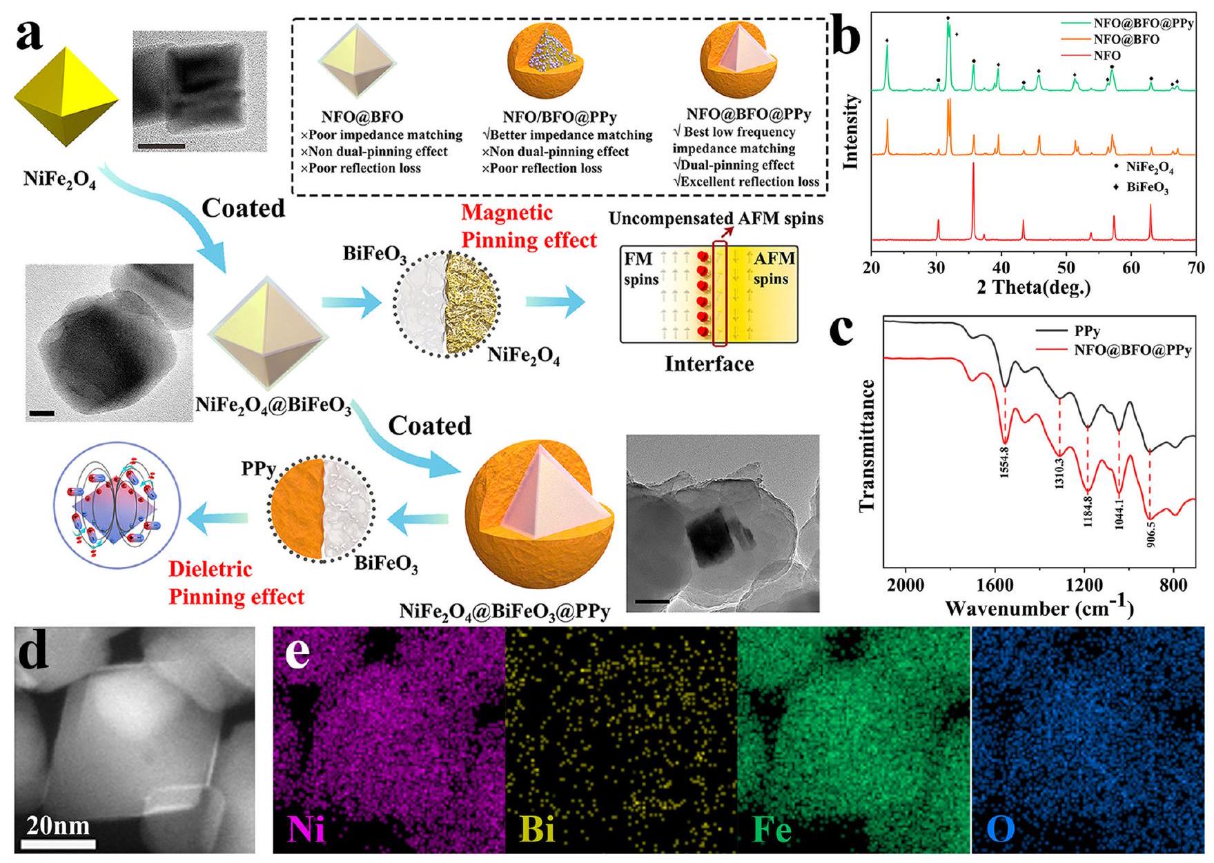
لدراسة آلية فقدان EMW في التردد المنخفض الناتج عن الواجهة غير المتجانسة، تم تصميم وتصنيع واجهة انحياز مغناطيسي. أولاً، تم بناء هيكل نواة-قشرة من NFO و BFO لتشكيل واجهة انحياز مغناطيسي. نظرًا لتثبيت المغناطيسية البارز، تم تثبيت دوران اللحظات المغناطيسية في NFO المغناطيسي بواسطة اللحظات المغناطيسية غير المتوازنة حول الواجهة في BFO المضادة للمغناطيسية. ثانيًا، استنادًا إلى الخصائص الكهربائية لـ BFO وخصائص المغناطيسية المتغيرة لـ NFO، تم إنشاء مجال كهربائي داخلي، والذي يمكن أن يسبب تأثير تثبيت كهربائي لثنائي القطب للبوليمرات الموصل مثل PPy ويعزز بشكل أكبر فقدان الاستقطاب. وبالتالي، تم تصميم NFO@BFO@PPy بشكل عقلاني وتمت صياغته من خلال طريقة كيميائية رطبة بسيطة. (الشكل 1أ). تم لف NFO@BFO ثلاثي الأبعاد بواسطة طبقات نانو PPy لتشكيل هيكل نواة-قشرة (الأشكال التكميلية 1-4). توضح نمط XRD (الشكل 1ب) بالإضافة إلى نتائج TEM (الأشكال التكميلية 5، 6) وجود كل من سبينيل مكعب (Fd 3 m) و البيروفسكايت المعيني (R 3 c)، وتم إثبات وجود PPy من خلال طيف تحويل فورييه للأشعة تحت الحمراء (FTIR) (الشكل 1ج، المعلومات الداعمة). أثبتت تحليلات رسم الخرائط للطيف الطيفي (EDS) (الشكل 1هـ) وجود هيكل نواة-قشرة محدد جيدًا. وبالتالي، تم تصنيع مركبات نانو NFO@BFO@PPy ذات واجهة انحياز مغناطيسي بنجاح.
آلية التثبيت المغناطيسي
في البداية، تم التحقيق في آلية التثبيت المغناطيسي الناتجة عن الواجهة. وفقًا لحد سنوك (المعلومات الداعمة),
الحد الحرج لتطابق المقاومة في التردد المنخفض يكمن في صعوبة تنظيم التردد الطبيعي للرنين، الذي تحدده حقل الأنيسوتروبي المغناطيسي البلوري, في نطاق جيجاهرتز. لذلك، يصبح تحسين الحقل المكافئ للأنيسوتروبي المغناطيسي البلوري هو المفتاح لحل هذه الحدود.
يمكن توضيح تعزيز NFO@BFO للأنيسوتروبي المغناطيسي البلوري من خلال افتراض أن اللحظة المغناطيسية FM لجزيئات NFO تولد حقل مغناطيسي تبادلي, يعمل على اللحظة المغناطيسية غير المتوازنة للواجهة AFM من طبقة قشرة BFO. يمكن أن تساهم الفجوة الطاقية المقابلة،(حيث هو الفرق في معدل المغنطة)، في تثبيت عكس اللحظة المغناطيسية وإنتاج ظاهرة الانحياز المتبادل. وبالتالي، يمكن اعتبار كحد إضافي للأنيسوتروبي المغناطيسي (الشكل 2أ).
كإثبات للمفهوم، قمنا ببناء هيكل غير متجانس NFO@BFO ويمكن أن يعزز تأثير التثبيت بين AFM و FM بشكل فعال الأنيسوتروبي المغناطيسي البلوري. كما أثبتت حلقات الهسترسيس في الأشكال 2ب، ج، أن عينة NFO@BFO ذات الهيكل نواة-قشرة تمتلك حلقة هسترسيس (المنحنيات) الم displaced على طول محور المجال المغناطيسي بعد معالجة التبريد الميداني إلى درجة حرارة الغرفة مقارنةً بعينة NFO/BFO المختلطة جسديًا، التي تثبت عدم تماثلها وجود انحياز تبادلي ( ) في عينة NFO@BFO عند درجة حرارة الغرفة (الشكل التوضيحي 7) كما كشفت تفرع منحنيات ZFC و FC عن التعايش وظاهرة تأثير التبادل بين مراحل المغناطيسية الحديدية والمغناطيسية المضادة عند درجة حرارة الغرفة (الشكل التوضيحي 8).لقد أثبت تقييم منحنيات توزيع مجال التبديل (SFD) بشكل أكبر وجود ارتباط تبادلي أقوى لـ NFO@BFO (الشكل 2d)..
ظاهرة انحياز التبادل تنشأ من تأثير التثبيت المغناطيسي عند الواجهة بين مراحل المغناطيسية المعاكسة والمغناطيسية العادية، ويمكن أن يؤدي هذا التأثير إلى زيادةوفقًا لنموذج ستونر وولفاسيمكن التعبير عنه بعد المعادلة التالية:، حيث هو ثابت الأنيسوتروبي المغناطيسي الفعاليمكن تقديرها من خلال مقارنة خطوط الهسترسيس بين الاثنين باستخدام تقريب S-Wصيغتها المبسطة هو ، الذي يميليتم إعطاؤه بواسطة:، مما يمكن استنتاجه أن ( هو ثابت). من الواضح أن ميل الخط المستقيم الملائم أكبر لـ NFO@BFO ( ) مقارنة بـ (الشكل 2e)، والذي بدوره يُحسب ليكون أكبر . لذلك، يشكل NFO@BFO واجهة انحياز مغناطيسي من خلال الهيكل النواة-الغلاف، مما يؤدي بدوره إلى تحقيق مستوى أعلى من .
تم تحليل النفاذية المغناطيسية لعينات مختلفة للتحقق من آلية تعزيز امتصاص الموجات الكهرومغناطيسية من خلال تأثير التثبيت المغناطيسي. تظهر النتائج التجريبية (الشكل 2f، g) أن هيكل النواة والصدفة NFO@BFO@PPy NPs لديه نفاذية أولية أعلى.من 1.10 أكثر من NFO/BFO@PPy NPs المختلطة جسديًا بسبب الزيادة. بشكل أكثر أهمية، الـقيم NFO@BFO@PPy NPs أعلى من قيم NFO/BFO@PPy NPs في منطقة التردد المنخفض، بينما يظهر ذروة الرنين لـ NFO@BFO@PPy NPs عند 3.20 جيجاهرتز. تحتوي NFO@BFO@PPy NPs على كلا من العالية و أي، مرتفعفي نطاقات التردد المنخفض. تُظهر التحليلات السابقة أن تثبيت المغناطيس الناتج عن الواجهة يكسر حد سنوك وينتج عنه نفاذية مغناطيسية أعلى، مما يؤدي إلى تحسين مطابقة المعاوقة في نطاقات التردد المنخفض. في الوقت نفسه، تعزز النفاذية العالية الخسائر المغناطيسية، التي تنشأ بشكل رئيسي من خسائر الرنين في نطاقات التردد المنخفض (الشكل التوضيحي التكميلي 9)..
آلية تثبيت العوازل
إن تضعيف EW في النطاقات الترددية المنخفضة هو عامل تقييدي آخر بالإضافة إلى تحقيق تطابق المقاومة. يتمتع NFO@BFO@PPy بتمغنط كبير بسبب آلية تثبيت المغناطيس، مما يؤدي بدوره إلى توليد خسارة مغناطيسية كبيرة، وعند
الشكل 1 | مخطط مسار التخليق وخصائص النواة-القشرة ثنائية الطبقةجزيئات نانوية من بوليبيرول (NFO@BFO@PPy). مخطط لطريق تخليق جزيئات NFO@BFO@PPy وآلية تأثير التثبيت المزدوج. تم الحصول على الصور المرفقة بواسطة مجهر الإلكترون الناقل (TEM). القضبان المقياسية هي كما يلي: 20 نانومتر (NFO)، 20 نانومتر (NFO@BFO)، 100 نانومتر (NFO@BFO@PPy). يمثل المربع الأحمر في الصورة المرفقة عند الواجهة تتشكل سبينات مضادة للمغناطيسية غير المعوضة عند واجهة المغناطيسية الفيرومغناطيسية والمضادة للمغناطيسية. تشير الدائرة الزرقاء في الصورة المصغرة إلى تأثير الحاجز الناتج عن المجال الكهربائي السطحي المتولد في BFO على انحراف ثنائي القطب في PPy. ب. مخطط XRD لـ NFO و NFO@BFO و NFO@BFO@PPy. ج. مخطط FTIR لـ NFO@BFO@PPy و PPy. د. STEM لـ NFO@BFO@PPy. هـ. صور رسم الخرائط العنصرية EDX لـ NFO@BFO NPs. تم توفير بيانات المصدر كملف بيانات مصدر. في نفس الوقت، يمكن أن يؤدي واجهة الانحياز المغناطيسي الكهربائي إلى تحفيز تأثير تثبيت العازل لزيادة فقدان الاستقطاب. بشكل أكثر تحديدًا، فإن حقل الانحياز التبادلي المغناطيسي يحفز المغناطيسية.ويحفز بعد ذلك الكهروإجهادي لـ BFO، مما يشكل مجال كهربائي داخلي متحيز (NFO@BFO + المجالات المغناطيسية)يمكن أن يثبت هذا المجال الكهربائي السطحي الدوران المتكرر للثنائيات في طبقة قشرة الـ PPy تحت المجال الكهرومغناطيسي المتناوب (الشكل التكميلي 10)، مما يعزز بشكل أكبر فقدان الاسترخاء الناتج عن الاستقطاب في النطاقات الترددية المنخفضة (الشكل 3أ).
تمت دراسة خصائص تحويل المغناطيسية الكهربائية لجزيئات نانو NFO@BFO ذات النواة والقشرة من خلال مجهر استجابة القوة الكهروستاتيكية (PFM) (الشكل 3ب، ج). توضح حلقة الطور المستخلصة أن قشرة BFO تظهر قابلية عكس الاستقطاب بغض النظر عن وجود المجال المغناطيسي المطبق. في غياب المجال المغناطيسي، كانت جهود التثبيط لقشرة BFO هي -31.97 فولت و55.81 فولت، بينما كانت جهود التثبيط مع تطبيق المجال المغناطيسي هي -23.99 فولت و32.04 فولت. تشير جهود التثبيط الأصغر إلى أن الإجهاد الناتج في نواة NFO المغناطيسية يتم نقله بفعالية إلى مادة BFO الكهروستاتيكية، مما يعزز عملية عكس الاستقطاب في BFO. بالإضافة إلى ذلك، فإن التغير في جهد التثبيط الإيجابي (22.37 فولت) أكبر من التغير في جهد التثبيط السلبي (7.98 فولت)، مما يوضح أن مركز حلقة الاستجابة الكهروستاتيكية قد تم تحريكه بواسطة المغناطيسية. المجال، الذي يثبت أن التأثير المغناطيسي الكهربائي يولد مجالًا كهربائيًا متحيزًاتم حساب معامل الاقتران المغناطيسي الكهربائي ليكونوالتي لها نفس ترتيب الحجم مثل قيم معامل الاقتران المغناطيسي الكهربائي المباشر المقدرة للهياكل النانوية ذات النواة والقشرة الأخرى باستخدام طرق قياس مماثلة. هذا يُظهر أن تأثير المغناطيسية الكهربائية المدعوم بالضغط يجعل NFO@BFO كمنشط فريد من نوعه في الربط المغناطيسي الكهربائي. وقد أكدت المحاكاة النظرية وظيفة حقل التبادل الذي يُحدث المغناطيسية في نواة NFO ويبدأ في نفس الوقت استقطاب الجهد في غلاف BFO. هذا يثبت أن NFO@BFO NP يمكن أن يُحدث جهدًا سطحيًا محليًا عند تعرضه لحقل مغناطيسي مائل (الشكل 3d-g والأشكال التكميلية 11، 12).
استفد من تأثير التثبيت الكهربائي، حيث يتم تحسين النفاذية العازلة للمركبات بشكل كبير في نطاقات التردد المنخفض. كما هو موضح في الشكل التكميلي 13، فإن هيكل النواة-القشرة ثنائي الطبقات NFO@BFO@PPy NPs لديه أعلى و مقارنةً مع نواة NFO/BFO@PPy NPs المدمجة جسديًا، مما يشير إلى زيادة سعة تخزين الطاقة وتفريغها للطاقة الكهربائية مع القدرة على فقدان العزل. زيادة فقدان المغناطيسية ( ) وفقدان العزل ( يمكن أن تنشأ من تأثير واجهة التثبيت المزدوج، الذي يعزز خسائر الاستقطاب ثنائي القطب، وخسائر الواجهة، والخسائر المغناطيسية (الشكل التكميلي 14).
الشكل 2 | دليل تخطيطي وتجريبي لآلية التثبيت المغناطيسي. أ مخطط تخطيطي لآلية التثبيت المغناطيسي. تمثل الظلال الحمراء والزرقاء المراحل المغناطيسية الحديدية (FM) والمغناطيسية المضادة (AFM) على التوالي. يعتبر تأثير التبادل ظاهرة تحدث عندما يتم ربط المغناطيسية الحديدية (NFO) والمغناطيسية المضادة (BFO) لإنتاج تحول في حلقة الهسترس من خلال التبريد في المجال عند درجات حرارة أعلى من درجة حرارة نيل. ) وأسفل درجة حرارة كورييمثل مجال تبادل الانحياز.منحنيات. ج مكبرةالمنحنيات لـ NFO@BFO و NFO/BFO. رسم SFD. e مقابل المؤامرات. الـالملاءمات الخطية لـ NFO@BFO و NFO/BFO هي 0.9988 و 0.9989 على التوالي. تحليل المعلمات المغناطيسية لـ NFO@BFO@PPy و NFO/BFO@PPy f الجزء الحقيقي من النفاذية. g الجزء التخيلي من النفاذية. تم توفير بيانات المصدر كملف بيانات مصدر.
خصائص امتصاص الموجات الكهرومغناطيسية
للتحقق من تأثير التثبيت المزدوج الناتج عن الواجهة، تم حساب وتحليل معلمات EM لعينات مختلفة (الأشكال التكميلية 15، 16).عينة NFO@BFO@PPy ذات النواة الثنائية الطبقات تمتلك تحسينًا كبيرًا في خاصية امتصاص الموجات الكهرومغناطيسية، مستفيدة من آلية التثبيت المزدوجة الناتجة عن واجهة الانحياز المغناطيسي الكهربائي. على وجه التحديد، مقارنةً بعينات NFO/BFO@PPy التي لا تعمل بهذه الآلية، فإنها تحقق امتصاصًا أقل بكثير يبلغ -65.30 ديسيبل (الكفاءة المثلى للامتصاص لـ)يمكن تحقيقه عند 5.68 جيجاهرتز لـ NFO@BFO@PPy بسمك 4.43 مم. (الشكل 4أ، ب). عرض نطاق الامتصاص الفعال (EAB) لمركب NFO@BFO@PPy هووينتقل نحو ترددات أقل بمعدل ملء يبلغ فقط (الشكل التوضيحي الإضافي 17). هناك معلمان مهمان يحددان أي، مطابقة المعاوقة ( ) وثابت التوهين ( )، يتم تحليلها بشكل إضافي (الشكل التوضيحي التكميلي 18) من ناحية، يظهر NFO@BFO@PPy توافقًا أقل في التردد تحت آلية التثبيت المزدوج (الشكل 4c)؛ ومن ناحية أخرى، يحقق تحسينًا كبيرًا في التوهين عبر النطاق الكامل مقارنةً بـ NFO/BFO@PPy (الشكل 4d).
لتقييم قدرات التخفي الكهرومغناطيسي للمواد المركبة المُصنَّعة، تم تحديد نتائج محاكاة مقطع الرادار (RCS) للركائز من الموصل الكهربائي المثالي (PEC) المغطاة بـ NFO@BFO@PPy و NFO/BFO@PPy كما هو موضح في صورة شدة RCS ثلاثية الأبعاد، على التوالي (الشكل 4e، f والشكل التكميلي 19). يمكن ملاحظة أن الفتحة الرئيسية للورقة المغطاة بـ NFO@BFO@PPy لديها إشارة منعكسة أقل من تلك الخاصة بـ NFO/BFO@PPy، مما يشير إلى قدرات EMWA أقوى. كما يظهر الشكل 4g قيم RCS المحاكاة ثنائية الأبعاد في إلىنطاق درجة الكشف، حيث يظهر طلاء NFO@BFO@PPy أصغر إشارة RCS مع ذروة من. علاوة على ذلك،
طلاء NFO@BFO@PPy قلل من RCS في جميع نطاقات الزوايا، مما يثبت إمكانيته لتطبيقات التخفي على نطاق واسع (الشكل 4 ح).
مقارنة هذا العمل مع مواد EMWA ذات التردد المنخفض التي تم دراستها في السنوات الأخيرة (الشكل 5، الجدول S2)تظهر مادة المركب ذات الهيكل الثنائي الطبقات NFO@BFO@PPy المقترحة في هذه الدراسة قدرة شاملة على التخفي الراداري مع فقدان كبير في الانعكاس وعرض نطاق امتصاص عالٍ مع كمية تعبئة منخفضة في النطاقات الترددية المنخفضة، مما يوفر توجيهًا قيمًا لأبحاث المواد المتقدمة في مجال EMWA ذات الترددات المنخفضة.
باختصار، تم اقتراح آلية امتصاص ذات تردد منخفض تعتمد على آلية تثبيت مزدوجة مستحثة بواسطة واجهة مغناطيسية كهربائية في هذا العمل وتم التحقق منها من خلال بناء هيكل نواة وقشرة ثنائي الطبقات NFO@BFO@PPy. يسمح إنشاء آلية التثبيت المزدوجة المستندة إلى التأثير التآزري للربط المغناطيسي الكهربائي بتحسين مطابقة impedances ذات التردد المنخفض وتعزيز التخفيف، مما يحسن الفقد الفعال لموجات EM ذات التردد المنخفض. كما تؤكد اختبارات EMWA والمحاكاة تفوق هذه الآلية من كلا الجانبين التجريبي والنظري معًا، مما يحقق بمقدار -65.30 ديسيبل عند سمك 4.43 مم، و EAB التي تغطي تقريبًا نطاق C-band ( بمعدل تعبئة يبلغ فقط . لا يوسع هذا العمل فقط الطريق لبحث مواد EMWA ذات التردد المنخفض، بل يمكنه أيضًا دعم تحسين قاعدة بيانات مواد EMWA.
طرق
تركيب (NFO)@BiFeO (BFO) @بوليبيرول (PPy)
لصنعجزيئات نانوية (NFO)، 0.187 م بروميد هكسادسيل تريميثيل أمونيوم (CTAB)،و 0.0613 م
الشكل 3 | دليل تخطيطي وتجريبي لآلية تثبيت العازل. أ مخطط تخطيطي لآلية تثبيت العازل. تشير التظليل الأصفر في الزاوية إلى أنه لا يتم توليد مجال كهربائي داخلي متحيز، وتمثل التظليل الأحمر والأزرق الأقطاب الموجبة والسالبة لمجال الكهرباء الداخلي المتحيز. بفضل الهيكل الأساسي-الصدفي لـ NFO@BFO، يتم نقل التشوه الناتج عن المغناطيسية لـ NFO إلى طبقة القشرة BFO، مما يتسبب في توليد مجال كهربائي داخلي مدمج، والذي يعمل كعائق أمام انحراف ثنائي القطب في PPy.استجابة الطور لجسيم نانوي ذو نواة وقشرة واحدة تم الحصول عليها بواسطة
ودون مجال مغناطيسي.استجابة السعة المقابلة. تُظهر محاكاة COMSOL لجزيئات NFO@BFO تحت مجال مغناطيسي قدره 3.0 مللي تسلامعيار المغنطة. e الإجهاد الناتج على غلاف BFO بسبب تأثير المغنطيسية لنواة NFO وإجهاد فون ميسيس. توزيع إجهاد الحجم، و الجهد الكهربائي المقابل المتولد على سطح قشرة BFO. وحدات الأسطورة هي كما يلي: أورستد، و تُقدم بيانات المصدر كملف بيانات مصدر. تم إذابتها في 60 مل من الماء المقطر. ثم، أضيف 20 مل من محلول NaOH بتركيز 6 م إلى المحلول السابق وتمت الموجات فوق الصوتية تحت تحريك قوي. أخيرًا، تم نقل المحلول السابق إلى أوتوكلاف فولاذي مبطن بتفلون سعة 100 مل وتم تسخينه عندلمدة 24 ساعة. تم غسل المسحوق الناتج بالماء المقطر والإيثانول وتجفيفه عند.
ثم، الـتم تحضير محلول السلف بواسطة إذابة و في الإيثيلين غليكول. تم توزيع 0.17 جرام من جزيئات نانو NFO المجففة في 20 مل من محلول سلف BFO باستخدام كسارة خلايا، ثم تم إزالة المحلول من الإيثيلين غليكول فيحمام مائي، وتمت معالجة المسحوق الناتج عندلمدة ساعتين بمعدل تسخين قدرهتم تحسين جزيئات NFO@BFO بواسطة طريقة تم الإبلاغ عنها سابقًا.
أخيرًا، 0.100 جرام من حمض الباراميثوكسي بنزين السلفونيك (TsOH)، 0.800 جرام من بولي إيثيلين-بولي بروبيلين غليكول (P123، متوسط )، وتم إذابة 9.10 مل من حمض الهيدروكلوريك المركز ( 12 م ) في 120 مل من الماء المقطر. تم توزيع 0.200 غرام من جزيئات نانو NFO@BFO في المحلول أعلاه، ثم أضيف 0.400 مل من مونومر البيرول وتم التحريك بقوة تحت حمام مائي مثلج. عندما وصلت درجة حرارة النظام إلى تم إضافة 2.73 جرام من بيرسلفات الأمونيوم المذاب في الماء المنزوع الأيونات، وتم إجراء التفاعل لمدة ساعتين. تم غسل المسحوق الناتج بالماء المنزوع الأكسجين والإيثانول وتجفيفه تحت الفراغ عندللحصول على جزيئات NFO@BFO@PPy.
خصائص المواد
تمت دراسة مورفولوجيا الجسيمات النانوية الناتجة بواسطة المجهر الإلكتروني الناقل (TEM، JEOL 2200FS وJEOL 2100F) والمجهر الإلكتروني الماسح (SEM، JSM 7500F). قبل قياسات SEM، تم طلاء سطح العينات بالذهب باستخدام جهاز الرش المغناطيسي (MSP-1S) لمدة دقيقة و15 ثانية. تم دراسة توزيع العناصر على طول الجسيمات النانوية NFO@BFO باستخدام رسم خرائط الأشعة السينية المشتتة للطاقة (EDX) بواسطة المجهر الإلكتروني الناقل الماسح (STEM، JEOL 2200FS، 200 كيلوفولت). تم دراسة التركيب البلوري المحلي بواسطة حيود الإلكترون في المنطقة المختارة (SAED). تم تحليل التركيب البلوري للهياكل النانوية بواسطة حيود الأشعة السينية (XRD) على جهاز حيود الأشعة السينية Bruker D8 Advance المزود بهدف نحاسي عند طول موجي منتم إجراء قياسات طيف الأشعة تحت الحمراء باستخدام تحويل فورييه (FTIR) على جهاز مطياف FTIR (Thermo INX10).
تم إجراء الخصائص المغناطيسية على جهاز قياس مغناطيسي للتداخل الكمي (SQUID) من تصميم كوانتم (Quantum Design MPMS 3). تعتمد درجة الحرارة على العزم المغناطيسي. : بالنسبة لعملية التبريد في المجال (FC)، تم تبريد العينة من 600 كلفن إلى 5 كلفن عند مجال 200 Oe. بالنسبة لعملية التبريد في حالة عدم وجود مجال (ZFC)، تم تبريد العينة من 600 كلفن إلى 5 كلفن في حالة عدم وجود مجال مغناطيسي، ثم تم تسخينها من 5 كلفن إلى 600 كلفن عند مجال مغناطيسي 200 Oe. الهسترس المغناطيسي ( تم قياس حلقة العينة عند، وتم إجراء نفس اختبار حلقة الهيسترسيس على العينة التي تم تبريدها إلى 300 كلفن.
الشكل 4 | تحليل ومقارنة خصائص امتصاص الموجات الكهرومغناطيسية للمواد المركبة. فقدان الانعكاس لـ NFO@BFO@PPy أ رسم بياني ثلاثي الأبعاد ملون. ب إسقاط ملون ثنائي الأبعاد. ج مطابقة impedence لـ NFO@BFO@PPy إسقاط ملون ثنائي الأبعاد.
الإسقاط. د مقارنة ثوابت التوهين. رسم ثلاثي الأبعاد لمقطع العرض السطحي للمواد الموصلة الكهربائية المغطاة بـ NFO@BFO@PPy. ف NFO/BFO@PPy. ج منحنى محاكاة مقطع العرض السطحي. ح تقليل مقطع العرض السطحي عند زوايا محددة. تم توفير بيانات المصدر كملف بيانات المصدر.
الشكل 5 | مركبات NFO@BFO@PPy مقارنة بأعمال أخرى لامتصاص الموجات الكهرومغناطيسية ذات التردد المنخفض (EMWA).هي التردد حيثيتم الحصول عليه. يتم توفير بيانات المصدر كملف بيانات المصدر.
تم إجراء مجهر القوة الذرية بتفاعل البيزوالكتروني (PFM) على مجهر قوة ذرية تجاري (OXFORD Asylum Research MFP-3D-Bio). تم التحكم بعناية في نقاط ضبط قوة الاتصال التصويري باستخدام مسبار ASYELEC-01-R2. للحصول على حلقة استجابة بيزوالكترونية محلية، تم تحويل المفتاح المستمر من -80 فولت إلى 80 فولت. تم تطبيق حقل مغناطيسي في المستوى بقوة 1000 Oe على العينة لدراسة تغير الاستجابة البيزوالكترونية تحت الحقل المغناطيسي.
تم إجراء توصيف EPR على مطياف الرنين المغناطيسي الإلكتروني (Bruker A300 10/12، Bruker، ألمانيا).
محاكاة متعددة الفيزياء لجزيئات NFO@BFO المغناطيسية الكهربائية
في هذه الدراسة، قمنا بإجراء محاكاة باستخدام برنامج COMSOL Multiphysics 6.0 استنادًا إلى أمثلة مشابهة من الأدبيات. تشمل محاكاة تأثير المغناطيسية الكهربائية لهيكل الجسيمات النانوية NFO-BFO ذات النواة والقشرة المجال المغناطيسي والميكانيكا والكهرباء الساكنة. في المحاكاة، تم اعتبار قشرة BFO المزروعة بشكل طبقي على مستوى [111] لنواة NFO وتم تنفيذها وفقًا لذلك في النموذج. سمك نانو كريستالات أكسيد الحديد الثلاثي (NFO) في طبقة النواة هو 94 نانومتر، وسمك القشرة من أكسيد البزموت الحديدي (BFO) هو 20 نانومتر، وشدة المجال المغناطيسي هي 3.0 مللي تسلا وتطبق على حدود الوسط على طول المحور العالمي z..
قياس امتصاص الموجات الكهرومغناطيسية
تم تحضير المركبات المستخدمة لقياس امتصاص الموجات الكهرومغناطيسية عن طريق خلط المنتجات مع نسب كتلة مختلفة من PVDF. ثم تم ضغط الخلائط لتشكيل عينات على شكل أسطواني. و ). تم قياس قيم السماحية المعقدة والنفاذية في نطاق باستخدام طريقة السلك المحوري بواسطة محلل الشبكات Agilent N5230C PNA-L.
توزيع المجال المتغير
يمكن تقييم درجة الاقتران التبادلي لعينة ما من خلال منحنى توزيع مجال التبديل (SFD)، وهو المشتق من الدرجة الأولى لمنحنى إزالة المغنطة، مع وجود قمة واحدة بالقرب من المجال المغناطيسي الصفري تشير إلى عملية التبديل المغناطيسي المتزامنة. تشير شدة القمة الأقوى إلى درجة أعلى من الاقتران التبادلي..
تقريب S-W
تقريب S-W هو طريقة تُستخدم عادةً لتحديد مجال الأنيسوتروبي المغناطيسي البلوري. يتم تعريفه في البداية على أنه :
أين هو الاستقطاب المغناطيسي المملوء و و هي ثوابت. الـ يُعرف هذا المصطلح بالصلابة المغناطيسية، هي الثوابت التي تعتمد على عدم تجانس العينات والتي تختفي عند الحقول المغناطيسية العالية. يُشار إلى هذا المصطلح غالبًا بالمصطلح المعروف باسم مصطلح الشبه مغناطيسية، هو الحساسية التفاضلية في المجال العالي التي تكون نشطة في تحليل درجات الحرارة العالية. ومن ثم، و يمكن تجاهل الشروط ويمكن تقليل المعادلة أعلاه إلى:
البيانات التجريبية للتغنط ) مقابل المجال المغناطيسي المطبق ( ) يصبح خطيًا عندما يقترب من الصفر ويمكن تضمينه في الدالة النسبية الإيجابية أعلاه.
معامل الاقتران المغناطيسي الكهربائي
يتم تعريف معامل الاقتران المغناطيسي الكهربائي على أنه :
أين هو مقدار تغير المجال المغناطيسي و هو مقدار تغيير المجال الكهربائي لكل وحدة طول بسبب المجال المغناطيسي المطبق، على التوالي. بالنسبة لجزيئات NFO@BFO، قيمة يمكن الوصول إلى:
وبالتالي، تحت ظروف متغيرة من المجال المغناطيسي الخارجي معمن 1000 Oe يمكن تقدير معامل الاقتران المغناطيسي الكهربائي المحلي على النحو التالي:
حسابات فقدان الانعكاس
فقدان الانعكاس هو مؤشر مهم لتقييم خصائص امتصاص الموجات الكهرومغناطيسية. وفقًا لنظرية خط النقل، فإنيمكن حساب القيمة باستخدام المعادلة التالية :
أين هو السماحية المعقدة، هو النفاذية المعقدة، يشير إلى سمك الطلاء،يقدم تردد الموجة الكهرومغناطيسية،هي سرعة الضوء في الفراغهو معامل الإدخال العادي، على التوالي.
كفاءة الامتصاص
تم حساب كفاءة امتصاص الميكروويف (%) من خلال استخدام خسارة الانعكاس المحصل عليها بوحدات الديسيبل باستخدام المعادلة التالية
حسابات مطابقة المعاوقة
يستخدم لدراسة خصائص مطابقة المعاوقة، والتي يمكن حسابها من خلال الصيغة التالية :
أينيعني مقاومة الإدخال الحقيقية العادية، عندماسيتم تحقيق مطابقة المثالية للمقاومة، مما يشير إلى أن أداء EMWA في هذا الوقت سيكون الأفضل.
ثابت التوهين ( ) حسابات
يقدر ثابت التوهين السعة المجمعة لفقدان الموجات الكهرومغناطيسية الساقطة ويمثل خصائص التوهين EWMA للمادة، والتي يتم تحديدها بالصيغة التالية :
حسابات مقطع الرادار المتناثر (RCS)
RCS هو المفهوم الأكثر أهمية في تكنولوجيا التخفي بالرادار، والذي يميز كمية فيزيائية لشدة الصدى الناتج عن الهدف عند تعرضه لموجات الرادار. بالنسبة لمصدر التشتت، فإن قيمة RCS الخاصة به (يمكن التعبير عن ( ) بالمعادلة التالية :
أينهي مساحة اللوحة، هو طول الموجة الكهرومغناطيسية الساقطة، و و هي شدة المجال الكهربائي للموجات المنبعثة والمستقبلة، على التوالي. تم استخدام CST STUDIO SUITE 2014 لمحاكاة قيم RCS للمواد المركبة NFO@BFO@PPy و NFO/BFO@PPy المعدة تحت ظروف الحدود المفتوحة. كان نموذج المحاكاة يتكون من طبقة موصل كهربائي مثالي (PEC) في الأسفل وطبقة ماصة بسمك 4.43 مم في الأعلى. كانت أبعاد الطول تساوي عرض 200 مم. ثم، تم وضع النموذج الذي تم إنشاؤه على المستوى، وتم إضافة الموجة الكهرومغناطيسية المستقطبة خطيًا مع اتجاه السقوط على-المحور من الموجب إلى السالب، وكان الاستقطاب الكهربائي على طول-المحور. بالإضافة إلى ذلك، تم تعيين تردد مراقبة المجال البعيد على 5.68 جيجاهرتز.
ملخص التقرير
معلومات إضافية حول تصميم البحث متاحة في ملخص تقارير مجموعة نيتشر المرتبط بهذه المقالة.
توفر البيانات
البيانات التي تدعم نتائج هذه الدراسة متاحة ضمن المقال والمعلومات التكميلية. تم توفير بيانات المصدر مع هذه الورقة.
References
Kim, M. et al. Analogue switches made from boron nitride monolayers for application in 5G and terahertz communication systems. Nat. Electron. 3, 479-485 (2020).
Zhang, Y., Dai, F., Mouldi, A., Bouallegue, B. & Akhtar, M. N. Tunable microwave absorption features in bi-layer absorber based on mesoporous CuS micro-particle with 3D hierarchical structure and nanosphere like . Ceram. Int. 48, 9146-9156 (2022).
Liu, L. Y. et al. Specific electromagnetic radiation in the wireless signal range increases wakefulness in mice. Proc. Natl Acad. Sci. USA 118, e2105838118 (2021).
Wang, Y. et al. Multi-dimensional C@NiCo-LDHs@Ni aerogel: Structural and componential engineering towards efficient microwave absorption, anti-corrosion and thermal-insulation. Carbon 191, 625-635 (2022).
Wen, C. Y. et al. High-density anisotropy magnetism enhanced microwave absorption performance in MXene@Ni microspheres. ACS Nano 16, 1150-1159 (2022).
Yuan, M. Y. et al. Remarkable magnetic exchange coupling via constructing bi-magnetic interface for broadband lower-frequency microwave absorption. Adv. Funct. Mater. 32, 2203161 (2022).
Liu, Q. H. et al. CoNi@SiO and CoNi@Air@TiO microspheres with strong wideband microwave absorption. Adv. Mater. 28, 486-490 (2016).
Gao, S., Wang, G.-S., Guo, L. & Yu, S.-H. Tunable and ultraefficient microwave absorption properties of trace N -doped two-dimensional carbon-based nanocomposites loaded with multi-rare earth oxides. Small 16, 1906668 (2020).
Rajhi, A. A., Alamri, S., Logesh, K., Mohanavel, V. & Akhtar, M. N. Synergistic effect of tuning nanocomposite morphology, composition and layer arrangement for boosting microwave dissipation performance. J. Magn. Magn. Mater. 563, 169955 (2022).
Gao, Z. G., Lan, D., Zhang, L. M. & Wu, H. J. Simultaneous manipulation of interfacial and defects polarization toward Co phase and ion hybrids for electromagnetic wave absorption. Adv. Funct. Mater. 31, 2106677 (2021).
Liu, P. B. et al. Hierarchical engineering of double-shelled nanotubes toward hetero-interfaces induced polarization and microscale magnetic interaction. Adv. Funct. Mater. 32, 2202588 (2022).
Liu, J. W. et al. Microwave absorption enhancement of multifunctional composite microspheres with spinel cores and anatase shells. Small 8, 1214-1221 (2012).
Huang, X. G. et al. Ultralight magnetic and dielectric aerogels achieved by metal-organic framework initiated gelation of graphene oxide for enhanced microwave absorption. Nanomicro Lett. 14, 107 (2022).
Liang, L. Y. et al. Multifunctional magnetic MXene/graphene aerogel with superior electromagnetic wave absorption performance. ACS Nano 15, 6622-6632 (2021).
Zhao, B. et al. High-entropy enhanced microwave attenuation in titanate perovskites. Adv. Mater. 35, 2210243 (2023).
Quan, B. et al. Defect engineering in two common types of dielectric materials for electromagnetic absorption applications. Adv. Funct. Mater. 29, 1901236 (2019).
Low, J. X., Yu, J. G., Jaroniec, M., Wageh, S. & Al-Ghamdi, A. A. Heterojunction photocatalysts. Adv. Mater. 29, 1601694 (2017).
Cao, M.-S. et al. Electronic structure and electromagnetic properties for 2D electromagnetic functional materials in gigahertz frequency. Ann. Phys. 531, 1800390 (2019).
Wang, W., Guo, J. X., Long, C., Li, W. & Guan, J. G. Flaky carbonyl iron particles with both small grain size and low internal strain for broadband microwave absorption. J. Alloy. Compd. 637, 106-111 (2015).
Suszka, A. K., Idigoras, O., Nikulina, E., Chuvilin, A. & Berger, A. Crystallography-driven positive exchange bias in bilayers. Phys. Rev. Lett. 109, 177205 (2012).
You, W. B. & Che, R. C. Excellent NiO-Ni nanoplate microwave absorber via pinning effect of antiferromagnetic-ferromagnetic interface. ACS Appl. Mater. Interfaces 10, 15104-15111 (2018).
Bai, J., Abdelbasset, W. K., Elkholi, S. M., Ismail, K. A. & Akhtar, M. N. Efficient single and bi-layer absorbers of micro-cubes and polypyrrole nanotubes composites for enhanced microwave absorption in X and Ku band. Ceram. Int. 48, 11953-11961 (2022).
Wang, C. H. et al. Exchange bias in spin-glass-like heterojunction at room temperature. J. Magn. Magn. Mater. 449, 372-377 (2018).
Gu, J. J. et al. Effects of on magnetoelectric coupling effect of thin films. J. Magn. Magn. Mater. 349, 140-143 (2014).
Tiwari, D. C., Atri, P. & Sharma, R. Sensitive detection of ammonia by reduced graphene oxide/polypyrrole nanocomposites. Synth. Met. 203, 228-234 (2015).
Bashir, T. et al. Polypyrrole- nanocomposites with high dielectric constant: in situ chemical polymerisation. Polym. Polym. Compos. 26, 233-241 (2018).
Snoek, J. L. Gyromagnetic resonance in ferrites. Nature 160, 90-90 (1947).
Houbi, A. et al. Microwave absorbing properties of ferrites and their composites: a review. J. Magn. Magn. Mater. 529, 167839 (2021).
Skumryev, V. et al. Beating the superparamagnetic limit with exchange bias. Nature 423, 850-853 (2003).
Kiwi, M. Exchange bias theory. J. Magn. Magn. Mater. 234, 584-595 (2001).
Bi, H., Li, S. D., Zhang, Y. C. & Du, Y. W. Ferromagnetic-like behavior of ultrafine NiO nanocrystallites. J. Magn. Magn. Mater. 277, 363-367 (2004).
Zaigham, H. & Khalid, F. A. Exchange coupling and magnetic behavior of alloys. J. Mater. Sci. Technol. 27, 218-222 (2011).
Camarero, J. et al. Origin of the asymmetric magnetization reversal behavior in exchange-biased systems: competing anisotropies. Phys. Rev. Lett. 95, 057204 (2005).
Collocott, S. J. Application of the Stoner-Wohlfarth model with interaction for the determination of the saturation magnetisation, anisotropy field, and mean field interaction in bulk amorphous ferromagnets. J. Magn. Magn. Mater. 323, 2023-2031 (2011).
Zhang, H., Zeng, D. C. & Liu, Z. W. The law of approach to saturation in ferromagnets originating from the magnetocrystalline anisotropy. J. Magn. Magn. Mater. 322, 2375-2380 (2010).
Kumari, K. et al. Investigating the magnetocrystalline anisotropy and the exchange bias through interface effects of nanocrystalline FeCo. J. Korean Phys. Soc. 79, 1180-1189 (2021).
Li, T. et al. Electromagnetic response of multistage-helical nanomicro conducting polymer structures and their enhanced attenuation mechanism of multiscale-chiral synergistic effect. Small 19, 2300233 (2023).
Akhtar, M. N. et al. Microwave absorption, physicochemical, elemental mapping, and high-frequency perspectives of the , Zn doped Ni-Ce absorbers for Ku band frequency. Surf. Interfaces 42, 103377 (2023).
Ji, M. et al. Multi-interface-induced by regulating nanocomposite morphology and absorber design to achieve wideband electromagnetic wave absorber. Ceram. Int. 49, 8071-8080 (2023).
Lage, E. et al. Exchange biasing of magnetoelectric composites. Nat. Mater. 11, 523-529 (2012).
Mushtaq, F. et al. Magnetoelectrically driven catalytic degradation of organics. Adv. Mater. 31, 1901378 (2019).
Wu, T.-M., Chang, H.-L. & Lin, Y.-W. Synthesis and characterization of conductive polypyrrole with improved conductivity and processability. Polym. Int. 58, 1065-1070 (2009).
Ding, J. J. et al. Boosted interfacial polarization from multishell heterojunction for enhanced microwave absorption. Small 15, 1902885 (2019).
Chen, X.-Z. et al. Hybrid magnetoelectric nanowires for nanorobotic applications: fabrication, magnetoelectric coupling, and magnetically assisted in vitro targeted drug delivery. Adv. Mater. 29, 1605458 (2017).
Caruntu, G., Yourdkhani, A., Vopsaroiu, M. & Srinivasan, G. Probing the local strain-mediated magnetoelectric coupling in multiferroic nanocomposites by magnetic field-assisted piezoresponse force microscopy. Nanoscale 4, 3218 (2012).
Sun, H. et al. Cross-stacking aligned carbon-nanotube films to tune microwave absorption frequencies and increase absorption intensities. Adv. Mater. 26, 8120-8125 (2014).
Zhang, X.-J. et al. Tunable high-performance microwave absorption of hollow spheres constructed by nanosheets within ultralow filler loading. Adv. Funct. Mater. 28, 1800761 (2018).
Che, R. C., Zhi, C. Y., Liang, C. Y. & Zhou, X. G. Fabrication and microwave absorption of carbon nanotubes spinel nanocomposite. Appl. Phys. Lett. 88, 033105 (2006).
Che, R. C., Peng, L. -M., Duan, X. F., Chen, Q. & Liang, X. L. Microwave absorption enhancement and complex permittivity and permeability of Fe encapsulated within carbon nanotubes. Adv. Mater. 16, 401-405 (2004).
Zhao, P.-Y. et al. Electrospinning fabrication and ultra-wideband electromagnetic wave absorption properties of -doped carbon nanofibers. Nano Res. 15, 7788-7796 (2022).
Wu, Y. et al. Ultrabroad microwave absorption ability and infrared stealth property of nano-micro CuS@rGO lightweight aerogels. Nanomicro Lett. 14, 171 (2022).
Wang, T. S. et al. Graphene- nanohybrids: synthesis and excellent electromagnetic absorption properties. J. Appl. Phys. 113, 024314 (2013).
Wang, F. Y. et al. Efficient low-frequency microwave absorption and solar evaporation properties of nanocubes/graphene composites. Chem. Eng. J. 405, 126676 (2021).
Yang, H. L. et al. 1D-3D mixed-dimensional @nanoporous carbon composites derived from Mn-metal organic framework with full-band ultra-strong microwave absorption response. Chem. Eng. J. 417, 128087 (2021).
Liu, X. F., Hao, C. C., Jiang, H., Zeng, M. & Yu, R. H. Hierarchical porous composite: a lightweight electromagnetic wave absorber with tunable absorbing performance. J. Mater. Chem. C 5, 3770-3778 (2017).
Xu, X. F. et al. Magnetic Ni/graphene connected with conductive carbon nano-onions or nanotubes by atomic layer deposition for lightweight and low-frequency microwave absorption. Chem. Eng. J. 382, 122980 (2020).
Liu, C. C. et al. Phthalocyanine-mediated interfacial selfassembly of magnetic graphene nanocomposites toward lowfrequency electromagnetic wave absorption. Chem. Eng. J. 452, 139483 (2003).
شكر وتقدير
تم دعم هذا العمل من قبل المؤسسة الوطنية للعلوم الطبيعية في الصين (رقم 52073010 و 52373259) (جي.-إس.دبليو.)، (رقم 52225308، 1197403) (إل.-إم.إل.) و (رقم 52371147) (بي.إتش.).
مساهمات المؤلفين
قام ج.-س.و، ب.هـ و ب.س. بتصور هذا المشروع. أعد ب.س، ب.-ي.ز و هـ.-ل.ب. العينات. قام ب.هـ و ب.س. بإجراء ملاحظات وتحليلات TEM. قام ب.س و ز.-ل.هـ بإجراء اختبارات أداء امتصاص الموجات الكهرومغناطيسية والدراسات الآلية. ساهم ل.ز و ز.-ل.هـ في المحاكاة التناظرية. شارك جميع المؤلفين في المناقشة. قام ل.-م.ل، ب.هـ و ب.س. بتحليل البيانات وكتابة هذا البحث.
يجب توجيه المراسلات والطلبات للحصول على المواد إلى بينغفاي هو، لي-مين ليو أو جوانغ-شينغ وانغ.
معلومات مراجعة الأقران تشكر مجلة Nature Communications ماجد نياز أختار والمراجعين الآخرين المجهولين على مساهمتهم في مراجعة هذا العمل. يتوفر ملف مراجعة الأقران.
معلومات إعادة الطباعة والتصاريح متاحة على http://www.nature.com/reprints ملاحظة الناشر: تظل شركة سبرينغر ناتشر محايدة فيما يتعلق بالمطالبات القضائية في الخرائط المنشورة والانتماءات المؤسسية.
مدرسة الكيمياء، جامعة بيهانغ، بكين 100191، الصين.كلية الرياضيات والفيزياء ومختبر بكين الرئيسي لتحليل المواد الكيميائية الضارة بيئيًا، جامعة بكين للتكنولوجيا الكيميائية، بكين 100029، الصين.معهد أبحاث محركات الطائرات، جامعة بيهانغ، بكين 100191، الصين.مدرسة الفيزياء، جامعة بيهانغ، بكين 100191، الصين.-البريد الإلكتروني: هوبينغفاي@بوا.edu.cn; liminliu@buaa.edu.cn; wanggsh@buaa.edu.cn
Improving the absorption of electromagnetic waves at low-frequency bands ( ) is crucial for the increasing electromagnetic (EM) pollution brought about by the innovation of the fifth generation ( 5 G ) communication technology. However, the poor impedance matching and intrinsic attenuation of material in low-frequency bands hinders the development of low-frequency electromagnetic wave absorbing (EMWA) materials. Here we propose an interface-induced dual-pinning mechanism and establish a magnetoelectric bias interface by constructing bilayer core-shell structures of (NFO) polypyrrole (PPy). Such heterogeneous interface could induce distinct magnetic pinning of the magnetic moment in the ferromagnetic NFO and dielectric pinning of the dipole rotation in PPy. The establishment of the dual-pinning effect resulted in optimized impedance and enhanced attenuation at low-frequency bands, leading to better EMWA performance. The minimum reflection loss ( ) at thickness of 4.43 mm reaches -65.30 dB (the optimal absorption efficiency of 99.99997%), and the effective absorption bandwidth (EAB) can almost cover C-band (4.72~7.04 GHz ) with low filling of . This work proposes a mechanism to optimize low-frequency impedance matching with electromagnetic wave (EMW) loss and pave an avenue for the research of high-performance low-frequency absorbers.
The fifth generation ( 5 G ) communication technology is developing rapidly with advantages of high network speed, low latency, high reliability, and low-power mass connectivity . However, the incidental electromagnetic (EM) pollution is becoming increasingly serious, and the high-performance electromagnetic wave absorbing (EMWA) materials that can effectively absorb EM pollution are urgently needed . Although high-performance EMWA materials can be obtained through material design strategies , the intrinsic wave impedance, which determines the external electromagnetic wave (EMW) incidence ratio and microwave dissipation capability, inevitably become
mismatching with decreasing frequency, leading to poor EMWA performance at 5 G frequency band . Therefore, exploring highperformance low-frequency EMWA strategies has become a top research priority.
Constructing heterogeneous structures is a feasible approach to overcome the intrinsic limits of EMWA materials, of which heterogeneous interface engineering play a very important role in optimizing the impedance matching and EMW attenuation . Examples include interfacial polarization , multiple scattering , and defect modulation , and these interfacial interactions thus have
fundamental effects on dipole polarization, conduction loss, and magnetic response , which could probably achieve controllable tuning of EMW absorption. The exchange bias effect between ferromagnetic (FM) and antiferromagnetic (AFM) materials, as a specific interface effect, could be a significant mechanism to adjust the EM parameters of the material . Che et al. constructed an AFM-FM system by forming heterojunction on the surfaces of NiO nanoplates. This structure induces pinning effect of the AFM phase ( NiO ) on the FM phase (Ni) and contribute to increasing permeability constant, which is more favorable for impedance matching and magnetic loss . Therefore, the in-depth and extended study of the interfacial pinning effect could provide a significant guidance for rational designing of low-frequency EMWA materials.
In this work, we propose an interface-induced dual-pinning mechanism and designed a distinct magnetoelectric bias interface through constructing bilayer core-shell structures of (NFO) polypyrrole (PPy) benefiting from the dual properties of ferromagnetism and magnetostriction of NFO, the dual properties of antiferromagnetism and piezoelectricity of BFO, combined with the strong ability of electron polarization of the conductive polymer . The interfacial magnetic pinning effect of the antiferromagnetic BFO on the ferromagnetic NFO is achieved by the magnetic bias effect, which effectively improves the magnetocrystalline anisotropy of the material, which in turn improves the lowfrequency permeability and optimizes the impedance in the lowfrequency bands. Meanwhile, the internal bias electric field generated by magnetoelectric driver NFO@BFO plays a role of electric field pinning on the inversion of dipoles, strengthening the relaxation of heterostructure and dielectric loss. The establishment of the dualpinning effect resulted in optimized impedance and enhanced attenuation at low-frequency bands, leading to better EW performance. Our work here promotes the in-depth comprehension of magnetoelectric bias interface mechanism and provides an approach for the rational design of high-performance low-frequency EW absorbers.
Results and discussion
Design and structures
In order to study the mechanism of low-frequency EMW loss induced by heterogeneous interface, a magnetoelectric bias interface was designed and fabricated. Firstly, a core-shell structure of NFO and BFO was constructed to form a magnetic bias interface. Owing to the prominent magnetic pinning , the rotation of magnetic moments in the ferromagnetic NFO was stuck by the uncompensated magnetic moments around the interface in the antiferromagnetic BFO. Secondly, based on the piezoelectric properties of the BFO and the magnetostrictive properties of the NFO, an internal bias electric field was established , which could cause electric pinning effect to dipolar of conductive polymers such as PPy and further enhance the polarization loss. Thus, NFO@BFO@PPy was rationally designed and synthesized through a simple wet-chemistry method. (Fig. 1a). The octahedra stereoscopic NFO@BFO was wrapped by PPy nanolayers to form core-shell structure (Supplementary Figs. 1-4). The XRD pattern (Fig. 1b) as well as TEM results (Supplementary Figs. 5, 6) demonstrate the coexistence of the cubic spinel ( Fd 3 m ) and the rhombohedral perovskite ( R 3 c ) , and the existence of PPy was proved by the Fourier transform infrared (FTIR) spectrum (Fig. 1c, Supporting Information) . Energy dispersive spectroscopy (EDS) mapping (Fig. 1e) analysis further proved the well-defined core-shell structure. Thus, the bilayer core-shell NFO@BFO@PPy nanocomposites with magnetoelectric bias interface were successfully synthesized.
Magnetic pinning mechanism
At first, the mechanism of interface-induced magnetic pinning was investigated. According to the Snoek limit (Supporting Information) ,
the critical limitation for low-frequency impedance matching lies in the difficulty in regulating the natural resonance frequency, which is determined by magnetocrystalline anisotropy field , into GHz range. Therefore, improving the equivalent field of magnetocrystalline anisotropy becomes the key to solve this limitation.
The enhancement of the NFO@BFO for magnetocrystal anisotropy can be illustrated by assuming that the FM magnetic moment of the NFO particles generates an exchange magnetic field , acting on the uncompensated magnetic moment of the interface AFM of the BFO shell layer. The corresponding energy difference, (where is the difference in the magnetization rate), could contribute to pin the reversal of the magnetic moment and produce the exchange bias phenomenon . Thus, can be considered as an additional magnetic anisotropy term (Fig. 2a).
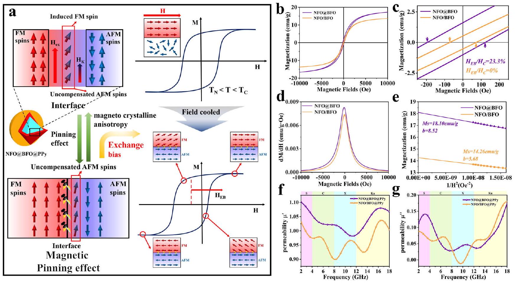
As a proof of concept, we constructed NFO@BFO heterogeneous structure and the pinning effect between AFM and FM could effectively enhance the magnetocrystalline anisotropy. As proved by the hysteresis loops in Figs. 2b, c, the core-shell structured NFO@BFO sample possesses a hysteresis loop ( curves) displaced along the magnetic field axis after field cooling to room temperature treatment compared to the physically co-mingled NFO/BFO sample, whose asymmetry proves the existence of an exchange bias ( ) in the NFO@BFO sample at room temperature (Supplementary Fig. 7) . The bifurcation of ZFC and FC curves also revealed the coexistence and the exchange bias phenomenon of FM and AFM phases at room temperature (Supplementary Fig. 8) . The evaluation of the Switching Field Distribution (SFD) curves further proved to a stronger exchange coupling of NFO@BFO (Fig. 2d) .
The exchange bias phenomenon originates from the magnetic pinning effect at the interface between the AFM and FM phases, and such pinning effect could lead to increasing . Following the Stoner and Wohlfass model, can be expressed after the following equation: , where is effective magnetic anisotropy constant could be estimated by comparing the hysteresis lines of the two using the S-W approximation . Its simplified formula is , which the slope is given by: , from which it can be concluded that ( is a constant). It is clear that the slope of the fitted straight-line is larger for the NFO@BFO ( ) compared to (Fig. 2e), which in turn is calculated to have a larger . Therefore, NFO@BFO forms a magnetic bias interface through the core-shell structure, which in turn yields a higher .
The magnetic permeability of different samples was analyzed to verify the mechanism of enhanced EMW absorption by the magnetic pinning effect. The experimental results (Fig. 2f, g) show that the coreshell structure NFO@BFO@PPy NPs have a higher initial of 1.10 than the physically co-mingled NFO/BFO@PPy NPs due to increasing . More significantly, the values of NFO@BFO@PPy NPs are higher than for NFO/BFO@PPy NPs in the low-frequency region, while the resonance peak of NFO@BFO@PPy NPs appears at 3.20 GHz . NFO@BFO@PPy NPs have both high and i.e., high , in the lowfrequency bands. The above analysis shows the interface-induced magnetic pinning breaks the snoek limit and produces a higher magnetic permeability, leading to optimized impedance matching in lowfrequency bands. Meanwhile, the high permeability enhances the magnetic losses, which mainly originate from the resonance losses in the low-frequency bands (Supplementary Fig. 9) .
Dielectric pinning mechanism
The attenuation of EW in low-frequency bands is another restrictive factor in addition to satisfying impedance matching. NFO@BFO@PPy has a large magnetic permeability due to the magnetic pinning mechanism, which in turn generates a large magnetic loss, and at the
Fig. 1 | Scheme of the synthesis route and characterization of bilayer core-shell polypyrrole (NFO@BFO@PPy) nanoparticles (NPs).
a Scheme of the synthesis route of NFO@BFO@PPy NPs and the mechanism of dual-pinning effect. The inset images were obtained by transmission electron microscopy (TEM). Scale bars are as follows: 20 nm (NFO), 20 nm (NFO@BFO), 100 nm (NFO@BFO@PPy). The red box in the interface inset represents the
uncompensated antiferromagnetic (AFM) spins formed at the ferromagnetic (FM) and AFM interface. The blue circle in the inset indicates the hindering effect of the surface electric field generated in the BFO on the dipole deflection in the PPy. b XRD plot of NFO, NFO@BFO, and NFO@BFO@PPy. c FTIR plot of NFO@BFO@PPy and PPy. d STEM of NFO@BFO@PPy. e the EDX elemental mapping images of NFO@BFO NPs. Source data are provided as a Source Data file.
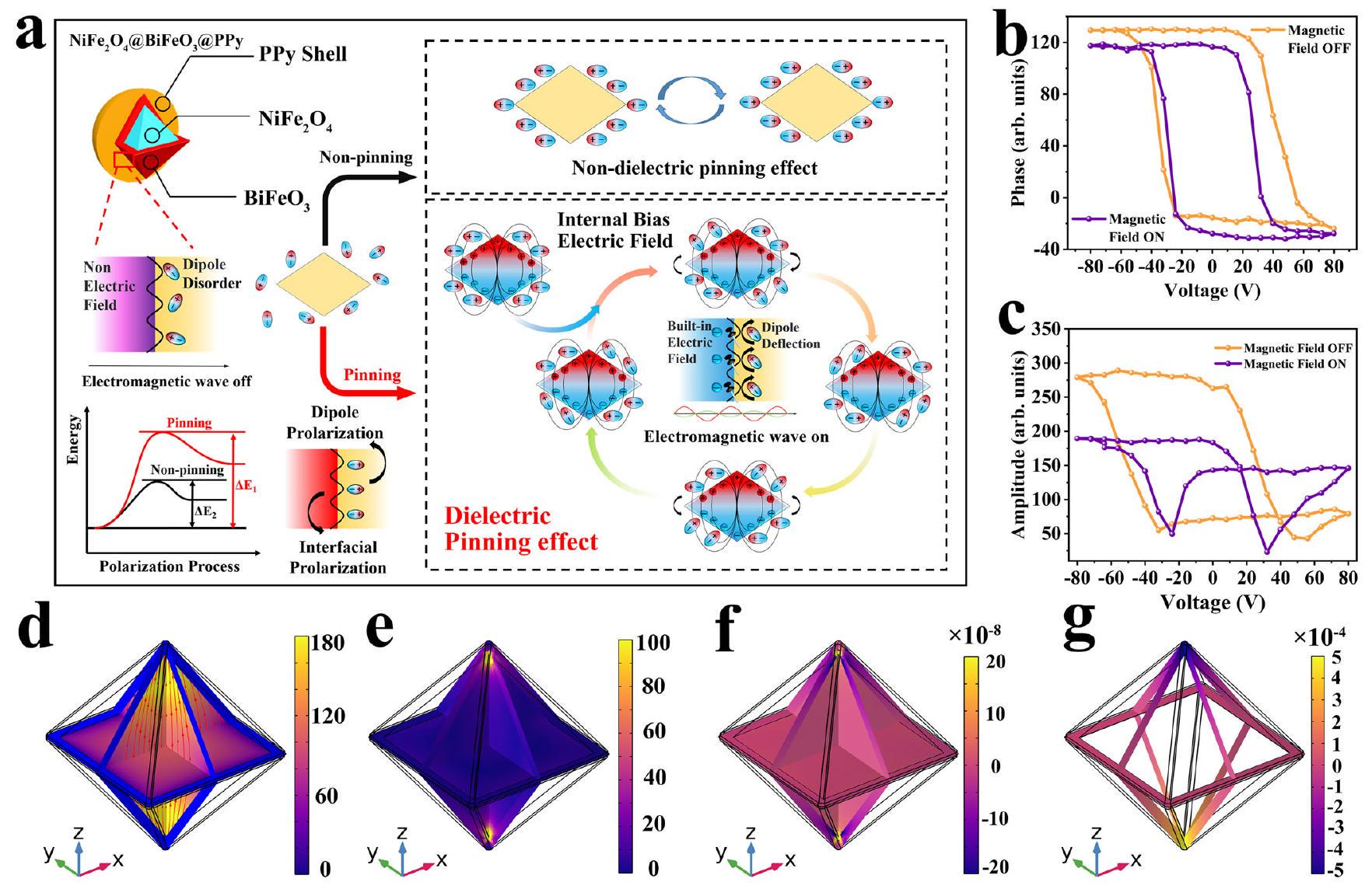
same time, its magnetoelectric bias interface could further induce a dielectric pinning effect to increase its polarization loss. More specifically, the exchange bias magnetic field induces the magnetostriction of and subsequently stimulates piezoelectricity of BFO , forming an internal bias electric field (NFO@BFO+Magnetic Fields . This surface electric field could pin the repeated rotation of the dipoles in the PPy shell layer under the alternating EM field (Supplementary Fig. 10) , further enhancing the relaxation loss caused by polarization in low-frequency bands (Fig. 3a) .
The magnetoelectric conversion properties of core-shell NFO@BFO NPs were characterized by piezoelectric response force microscopy (PFM) (Fig. 3b, c). The obtained phase loop demonstrates that the BFO shell exhibits polarization reversibility regardless of the presence of applied magnetic field. In the absence of magnetic field, the coercivity voltages of the BFO shell are -31.97 V and 55.81 V , while the coercivity voltages with the application of magnetic field are -23.99 V and 32.04 V . The smaller coercivity voltages indicate that the strain generated in the magnetostrictive NFO core is effectively transferred to the piezoelectric material BFO shell, which promotes the polarization reversal process in the BFO. Besides, the variation in positive coercivity voltage ( 22.37 V ) is larger than variation in negative coercivity voltage ( 7.98 V ), illustrating the center of the piezoelectric response loop is shifted by the magnetic
field, which proves that the magnetoelectric effect generates a bias electric field . The magnetoelectric coupling coefficient is calculated to be , which have the same order of magnitude as the direct magnetoelectric coupling coefficient values estimated for other core-shell nanostructures using similar measurement methods . This demonstrates the strain-mediated magnetoelectric effect renders NFO@BFO as a distinct magnetoelectric coupling actuator. Theoretical simulations further validated the exchange bias field function that induces magnetostriction in the NFO core and simultaneously initiates the BFO shell potential polarization. This proves that the NFO@BFO NP can induce a local surface potential when subjected to a bias magnetic field (Fig. 3d-g and Supplementary Figs. 11, 12) .
Benefit from the electric pinning effect, the dielectric permittivity of composites is significantly optimized at low-frequency bands. As shown in Supplementary Fig. 13, the bilayer core-shell structure NFO@BFO@PPy NPs have higher and compared to with the physically co-hybrid core NFO/BFO@PPy NPs, indicating enhanced energy storage and dissipation capacity of electric energy with dielectric loss capability. The increase of magnetic loss ( ) and dielectric loss ( ) could arise from dual-pinning interface effect, which enhances dipole polarization losses, interface losses, and magnetic losses (Supplementary Fig. 14) .
Fig. 2 | Schematic and experimental proof of the magnetic pinning mechanism. a Schematic diagram of the magnetic pinning mechanism. The red and blue shades represent the ferromagnetic (FM) and antiferromagnetic (AFM) phases, respectively. Exchange bias is a phenomenon that occurs when ferromagnetism (NFO) and antiferromagnetism (BFO) are coupled to produce a shift in the hysteresis loop through field cooling at temperatures above the Néel temperature ( ) and below
the Curie temperature denotes the exchange bias field. curves. c Enlarged curves for NFO@BFO and NFO/BFO. d SFD plot. e vs plots. The of the linear fits for NFO@BFO and NFO/BFO are 0.9988 and 0.9989 , respectively. Analysis of magnetic parameters of NFO@BFO@PPy and NFO/ BFO@PPy f permeability real part. g permeability imaginary part. Source data are provided as a Source Data file.
Electromagnetic wave absorbing properties
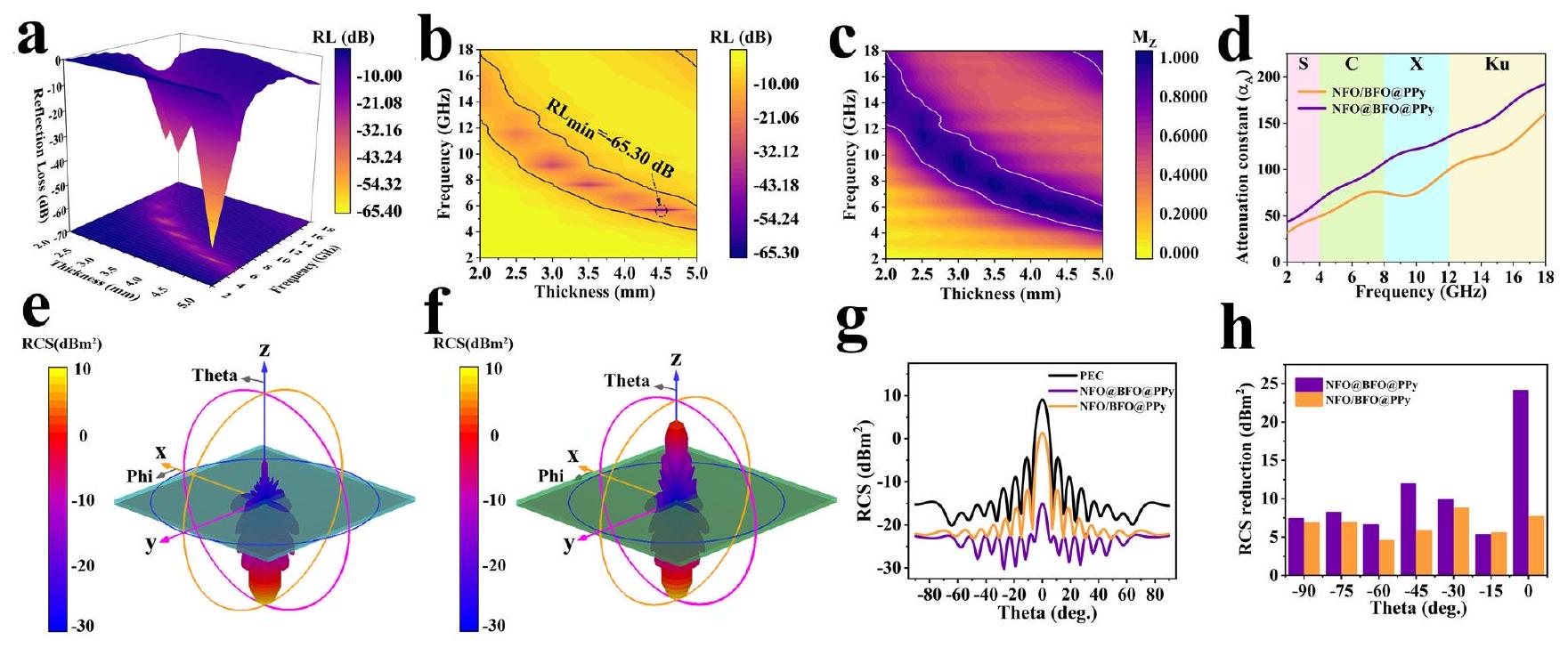
To verify the interface-induced dual-pining effect, the EM parameters of different samples were calculated and analyzed (Supplementary Figs. 15, 16) . The NFO@BFO@PPy sample with bilayer core-shell possess significant enhancement of EMW absorption property, benefiting from the dual-pining mechanism induced by the magnetoelectric bias interface. Specifically, compared with NFO/BFO@PPy samples that do not act by this mechanism, a much lower of -65.30 dB (the optimal absorption efficiency of can be achieved at 5.68 GHz for NFO@BFO@PPy with a thickness of 4.43 mm . (Fig. 4a, b). The effective absorption bandwidth (EAB) of the NFO@BFO@PPy composite is and shifts toward lower frequencies with a fill rate of only (Supplementary Fig. 17). Two important parameters that determine the , i.e., impedance matching ( ) and attenuation constant ( ), are further analyzed (Supplementary Fig. 18) . On the one hand, NFO@BFO@PPy exhibits a lower frequency impedance matching under the dual-pinning mechanism (Fig. 4c); on the other hand, it achieves a great full-band improvement in attenuation compared with NFO/BFO@PPy (Fig. 4d).
To further evaluate the EW stealth capabilities of the synthesized composites, Radar cross-section (RCS) simulation results of perfect electric conductor (PEC) substrates covered by NFO@BFO@PPy and NFO/BFO@PPy composites are figured out as shown in the threedimensional RCS intensity image, respectively (Fig. 4e, f and Supplementary Fig. 19). It can be seen that the main flap of the NFO@BFO@PPy coated PEC sheet has the lower reflected signal than that of NFO/BFO@PPy, indicating stronger EMWA abilities. Figure 4g also shows the two-dimensional simulated RCS values in the to detection degree range, with the NFO@BFO@PPy coating exhibiting the smallest RCS signal with a peak of . Moreover, the
NFO@BFO@PPy coating reduced the RCS more in all angle ranges, proving its potential for wide-angle stealth applications (Fig. 4 h.
Comparing this work with low-frequency EMWA materials studied in recent years (Fig. 5, Table S2) , the bilayer core-shell structure NFO@BFO@PPy composite material proposed in this study exhibit a comprehensive radar stealth capability with great reflection loss and high absorption bandwidth with low filling amount in the lowfrequency bands, providing valuable guidance for the research of advanced low-frequency EMWA materials.
In summary, a low-frequency absorption mechanism based on a magnetoelectric bias interface-induced dual-pinning mechanism is proposed in this work and validated by constructing a bilayer coreshell structure NFO@BFO@PPy. The establishment of a dualpinning mechanism based on the synergistic effect of magnetoelectric coupling allows the optimization of low-frequency impedance matching and attenuation enhancement, thus improving the effective loss of low-frequency EM waves. EMWA tests and simulations further validate the superiority of this mechanism from both experiments and theories together, achieving a of -65.30 dB at a thickness of 4.43 mm , and an EAB that almost covers the C-band ( ) with a fill rate of only . This work not only broadens the way for the research of low-frequency EMWA materials, but also can support the improvement of the database of EMWA materials.
Methods
The synthesis of (NFO)@BiFeO (BFO)
@polypyrrole (PPy)
To fabricate (NFO) nanoparticles, 0.187 M Hexadecyl trimethyl ammonium bromide (CTAB), and 0.0613 M
Fig. 3 | Schematic and experimental proof of the dielectric pinning mechanism. a Schematic diagram of the dielectric pinning mechanism. The yellow shading in the inset indicates that no internal bias electric field is generated, and the red and blue shading represent the positive and negative poles of the internal bias electric field. Benefiting from the core-shell structure of NFO@BFO, the deformation due to magnetostriction of the NFO is transferred to the BFO shell layer, causing it to generate a built-in internal electric field, which acts as a hindrance to the deflection of the dipole in the PPy. Phase response of a single core-shell NP obtained with
and without magnetic field. the corresponding amplitude response. COMSOL simulations of NFO@BFO NPs under a magnetic field of 3.0 mT show the magnetization norm. e the strain generated on the BFO shell due to the magnetostrictive effect of NFO core and von Mises stress. the volumetric strain distribution, and the corresponding electric potential induced on the surface of the BFO shell. The legend units are as follows: Oersted , and . Source data are provided as a Source Data file. were dissolved in 60 ml of DI water. Then, 20 ml of 6 M NaOH solution was added to the above solution and sonicated under vigorous stirring. Finally, the above solution was transferred to a sealed 100 ml Teflon-lined steel autoclave and heated at for 24 h . The obtained powder was washed with DI water and ethanol and dried at .
And then, the precursor solution was prepared by dissolving and in ethylene glycol. The 0.17 g of dried NFO nanoparticles were dispersed into 20 mL of BFO precursor solution using a cell crusher, and then the solution was removed from ethylene glycol in an water bath, and the resulting powder was annealed at for 2 h at a heating rate of . The NFO@BFO nanoparticle was improved by a previously reported method .
Finally, 0.100 g of p-toluene sulfonic acid (TsOH), 0.800 g of Polyethylene-polypropylene glycol (P123, average ), and 9.10 ml of concentrated hydrochloric acid ( 12 M ) were dissolved in 120 ml of DI water. 0.200 g of NFO@BFO nanoparticles were dispersed in the above solution, then 0.400 ml of pyrrole monomer was added and stirred vigorously under an ice water bath. When the temperature of the system reached of deionized water dissolved with 2.73 g of ammonium persulfate was added and the reaction was carried out for 2 h . The obtained powder was washed with deoxygenated water and ethanol and dried under vacuum at to obtain NFO@BFO@PPy nanoparticles.
Material characterizations
The morphology of the resulting nanoparticles was studied by transmission electron microscopy (TEM, JEOL 2200FS and JEOL 2100F) and scanning electron microscopy (SEM, JSM 7500F). Prior to SEM measurements, the surface of the samples was gold plated using the magnetron sputtering (MSP-1S) apparatus for 1 min 15 s . The distribution of elements along the NFO@BFO nanoparticles was studied using energy dispersive x-ray (EDX) mapping by scanning transmission electron microscopy (STEM, JEOL 2200FS, 200 kV ). The local crystal structure was studied by selected area electron diffraction (SAED). The crystal structure of the nanostructures was analyzed by X-ray diffraction (XRD) on a Bruker D8 Advance X-ray diffractometer equipped with a copper target at a wavelength of . Fourier transform infrared (FTIR) spectra measurements were performed on FTIR spectrometer (Thermo INX10) instrument.
The magnetic properties were carried out on a Quantum Design superconducting quantum interference device (SQUID) magnetometer (Quantum Design MPMS 3). The temperature dependence of the magnetic moment : For the field cooling (FC) process, the sample was cooled from 600 K to 5 K at 200 Oe field. For the zero-field cooling (ZFC) process, the sample was cooled from 600 K to 5 K at zero magnetic field and then heated from 5 K to 600 K at 200 Oe magnetic field. The magnetic hysteresis ( ) loop of the sample was measured at , and the same hysteresis loop test was performed for the sample cooled to 300 K .
Fig. 4 | Analysis and comparison of electromagnetic wave absorbing properties of composites. The reflection loss of NFO@BFO@PPy a 3D color mapping surface diagram. b 2D color projection. c NFO@BFO@PPy impedance matching 2D color
projection. d comparison of attenuation constants. 3D RCS plot for the PEC substrate covered with e NFO@BFO@PPy. f NFO/BFO@PPy. g RCS simulation curve. h RCS reduction at specific angles. Source data are provided as a Source Data file.
Fig. 5 | NFO@BFO@PPy composites compared to other low-frequency electromagnetic wave absorbing (EMWA) works. The is the frequency where is obtained. Source data are provided as a Source Data file.
Piezoelectric reaction force microscopy (PFM) was performed on a commercial atomic force microscope (OXFORD Asylum Research MFP-3D-Bio). Imaging contact force set points were carefully controlled using an ASYELEC-01-R2 probe. To obtain a local piezoelectric response loop, the DC switch is switched from -80 V to 80 V . An inplane magnetic field of 1000 Oe was applied to the sample in order to study the variation of piezoelectric response under magnetic field.
The EPR characterization was conducted on an electron paramagnetic resonance spectrometer (Bruker A300 10/12, Bruker, Germany).
Multiphysics simulation of magnetoelectric NFO@BFO NPs
In this study, we performed simulations in the COMSOL Multiphysics 6.0 software based on similar examples from literature. The magnetoelectric effect simulation of core-shell structure NFO-BFO nanoparticles includes magnetic field, mechanics, and electrostatics. In the simulation, an epitaxially grown BFO shell on the NFO core’s [111] plane was considered and implemented accordingly in the model. The
thickness of the octahedral NFO NP of the core layer is 94 nm , the thickness of the shell BFO is 20 nm , and the magnetic field intensity is 3.0 mT and applied on the boundaries of the medium along the global z-axis .
Electromagnetic wave absorption measurement
The composites used for electromagnetic wave absorption measurement were prepared by mixing the products with PVDF different mass percentages. The mixtures were then pressed into cylindrical-shaped samples ( and ). The complex permittivity and permeability values were measured in the range with coaxial wire method by an Agilent N5230C PNA-L Network Analyzer.
Switching Field Distribution
The degree of exchange coupling of a sample can be evaluated by the switching field distribution (SFD) curve, the first-order derivative of the demagnetization curve, with a single peak near the zero magnetic field indicating the synchronous magnetic switching process. A stronger peak intensity implies a higher degree of exchange coupling .
The S-W approximation
The S-W approximation is a method commonly used to determine the magnetocrystalline anisotropy field. It is defined initially as :
where is the saturation magnetization and and are constants. The term is known as the magnetic hardness, is the constants depends on inhomogeneity of samples that disappears at high magnetic fields. The term is often referred to as the so-called paramagnetism-like term, is the high-field differential susceptibility which is active in the high-temperature analysis. Hence, the and terms can be neglected and the above equation can reduced to:
The experimental data of magnetization ( ) versus applied magnetic field ( ) becomes linear when approaches zero and can be fitted into the positive proportional function above.
The magnetoelectric coupling coefficient
The magnetoelectric coupling coefficient is defined as :
where is the amount of magnetic field change and is the amount of electric field change per unit length due to the applied magnetic field, respectively. For NFO@BFO NPs, the value of can reach:
Thus, under changing conditions of external magnetic field with of 1000 Oe the local magnetoelectric coupling coefficient can be estimated as:
Reflection loss calculations
Reflection Loss is an important index to evaluate the EMW absorption properties. According to the transmission line theory, the value can be calculated by the following formula :
where is the complex permittivity, is the complex permeability, refers to the thickness of the coating, presents the frequency of the electromagnetic wave, is the velocity of light in free space is the normalized input impedance, respectively.
Absorption efficiency
The microwave absorption efficiency (%) was calculated from by employing the obtained reflection loss in dB used following equation
Impedance matching calculations
is used to study the impedance matching characteristics, which can be calculated by the following formula :
Where means the real normalized input impedance, when , the ideal impedance matching will be realized, indicating that the EMWA performance at this time will be the best.
The attenuation constant ( ) calculations
The attenuation constant estimates the combined loss capacity of incident electromagnetic waves and represents the EWMA attenuation characteristics of the material, which is determined by the following formula :
Radar scattering cross-section (RCS) calculations
RCS is the most critical concept in radar stealth technology, which characterizes a physical quantity of the intensity of the echoes generated by the target when exposed to radar waves. For a scattering source, its RCS value ( ) can be expressed by the following equation :
where is the area of the plate, is the length of the incident electromagnetic wave, and and are the electric field strengths of the emitted and received waves, correspondingly. CST STUDIO SUITE 2014 was applied to simulate the RCS values of as-prepared NFO@BFO@PPy and NFO/BFO@PPy composites under open boundary conditions. The simulation model consisted of the perfect electric conductor (PEC) layer at the bottom and an absorbing layer with a thickness of 4.43 mm on the top. The dimension of length was equal to the width of 200 mm . Then, the created model was placed on the plane, and the linear polarized plane electromagnetic wave was added with the incidence direction on -axis positive to negative, and the electric polarization was along the -axis. In addition, the far-field monitor frequency was set as 5.68 GHz .
Reporting summary
Further information on research design is available in the Nature Portfolio Reporting Summary linked to this article.
Data availability
The data supporting the findings of this study are available within the article and the Supplementary Information. Source data are provided with this paper.
References
Kim, M. et al. Analogue switches made from boron nitride monolayers for application in 5G and terahertz communication systems. Nat. Electron. 3, 479-485 (2020).
Zhang, Y., Dai, F., Mouldi, A., Bouallegue, B. & Akhtar, M. N. Tunable microwave absorption features in bi-layer absorber based on mesoporous CuS micro-particle with 3D hierarchical structure and nanosphere like . Ceram. Int. 48, 9146-9156 (2022).
Liu, L. Y. et al. Specific electromagnetic radiation in the wireless signal range increases wakefulness in mice. Proc. Natl Acad. Sci. USA 118, e2105838118 (2021).
Wang, Y. et al. Multi-dimensional C@NiCo-LDHs@Ni aerogel: Structural and componential engineering towards efficient microwave absorption, anti-corrosion and thermal-insulation. Carbon 191, 625-635 (2022).
Wen, C. Y. et al. High-density anisotropy magnetism enhanced microwave absorption performance in MXene@Ni microspheres. ACS Nano 16, 1150-1159 (2022).
Yuan, M. Y. et al. Remarkable magnetic exchange coupling via constructing bi-magnetic interface for broadband lower-frequency microwave absorption. Adv. Funct. Mater. 32, 2203161 (2022).
Liu, Q. H. et al. CoNi@SiO and CoNi@Air@TiO microspheres with strong wideband microwave absorption. Adv. Mater. 28, 486-490 (2016).
Gao, S., Wang, G.-S., Guo, L. & Yu, S.-H. Tunable and ultraefficient microwave absorption properties of trace N -doped two-dimensional carbon-based nanocomposites loaded with multi-rare earth oxides. Small 16, 1906668 (2020).
Rajhi, A. A., Alamri, S., Logesh, K., Mohanavel, V. & Akhtar, M. N. Synergistic effect of tuning nanocomposite morphology, composition and layer arrangement for boosting microwave dissipation performance. J. Magn. Magn. Mater. 563, 169955 (2022).
Gao, Z. G., Lan, D., Zhang, L. M. & Wu, H. J. Simultaneous manipulation of interfacial and defects polarization toward Co phase and ion hybrids for electromagnetic wave absorption. Adv. Funct. Mater. 31, 2106677 (2021).
Liu, P. B. et al. Hierarchical engineering of double-shelled nanotubes toward hetero-interfaces induced polarization and microscale magnetic interaction. Adv. Funct. Mater. 32, 2202588 (2022).
Liu, J. W. et al. Microwave absorption enhancement of multifunctional composite microspheres with spinel cores and anatase shells. Small 8, 1214-1221 (2012).
Huang, X. G. et al. Ultralight magnetic and dielectric aerogels achieved by metal-organic framework initiated gelation of graphene oxide for enhanced microwave absorption. Nanomicro Lett. 14, 107 (2022).
Liang, L. Y. et al. Multifunctional magnetic MXene/graphene aerogel with superior electromagnetic wave absorption performance. ACS Nano 15, 6622-6632 (2021).
Zhao, B. et al. High-entropy enhanced microwave attenuation in titanate perovskites. Adv. Mater. 35, 2210243 (2023).
Quan, B. et al. Defect engineering in two common types of dielectric materials for electromagnetic absorption applications. Adv. Funct. Mater. 29, 1901236 (2019).
Low, J. X., Yu, J. G., Jaroniec, M., Wageh, S. & Al-Ghamdi, A. A. Heterojunction photocatalysts. Adv. Mater. 29, 1601694 (2017).
Cao, M.-S. et al. Electronic structure and electromagnetic properties for 2D electromagnetic functional materials in gigahertz frequency. Ann. Phys. 531, 1800390 (2019).
Wang, W., Guo, J. X., Long, C., Li, W. & Guan, J. G. Flaky carbonyl iron particles with both small grain size and low internal strain for broadband microwave absorption. J. Alloy. Compd. 637, 106-111 (2015).
Suszka, A. K., Idigoras, O., Nikulina, E., Chuvilin, A. & Berger, A. Crystallography-driven positive exchange bias in bilayers. Phys. Rev. Lett. 109, 177205 (2012).
You, W. B. & Che, R. C. Excellent NiO-Ni nanoplate microwave absorber via pinning effect of antiferromagnetic-ferromagnetic interface. ACS Appl. Mater. Interfaces 10, 15104-15111 (2018).
Bai, J., Abdelbasset, W. K., Elkholi, S. M., Ismail, K. A. & Akhtar, M. N. Efficient single and bi-layer absorbers of micro-cubes and polypyrrole nanotubes composites for enhanced microwave absorption in X and Ku band. Ceram. Int. 48, 11953-11961 (2022).
Wang, C. H. et al. Exchange bias in spin-glass-like heterojunction at room temperature. J. Magn. Magn. Mater. 449, 372-377 (2018).
Gu, J. J. et al. Effects of on magnetoelectric coupling effect of thin films. J. Magn. Magn. Mater. 349, 140-143 (2014).
Tiwari, D. C., Atri, P. & Sharma, R. Sensitive detection of ammonia by reduced graphene oxide/polypyrrole nanocomposites. Synth. Met. 203, 228-234 (2015).
Bashir, T. et al. Polypyrrole- nanocomposites with high dielectric constant: in situ chemical polymerisation. Polym. Polym. Compos. 26, 233-241 (2018).
Snoek, J. L. Gyromagnetic resonance in ferrites. Nature 160, 90-90 (1947).
Houbi, A. et al. Microwave absorbing properties of ferrites and their composites: a review. J. Magn. Magn. Mater. 529, 167839 (2021).
Skumryev, V. et al. Beating the superparamagnetic limit with exchange bias. Nature 423, 850-853 (2003).
Kiwi, M. Exchange bias theory. J. Magn. Magn. Mater. 234, 584-595 (2001).
Bi, H., Li, S. D., Zhang, Y. C. & Du, Y. W. Ferromagnetic-like behavior of ultrafine NiO nanocrystallites. J. Magn. Magn. Mater. 277, 363-367 (2004).
Zaigham, H. & Khalid, F. A. Exchange coupling and magnetic behavior of alloys. J. Mater. Sci. Technol. 27, 218-222 (2011).
Camarero, J. et al. Origin of the asymmetric magnetization reversal behavior in exchange-biased systems: competing anisotropies. Phys. Rev. Lett. 95, 057204 (2005).
Collocott, S. J. Application of the Stoner-Wohlfarth model with interaction for the determination of the saturation magnetisation, anisotropy field, and mean field interaction in bulk amorphous ferromagnets. J. Magn. Magn. Mater. 323, 2023-2031 (2011).
Zhang, H., Zeng, D. C. & Liu, Z. W. The law of approach to saturation in ferromagnets originating from the magnetocrystalline anisotropy. J. Magn. Magn. Mater. 322, 2375-2380 (2010).
Kumari, K. et al. Investigating the magnetocrystalline anisotropy and the exchange bias through interface effects of nanocrystalline FeCo. J. Korean Phys. Soc. 79, 1180-1189 (2021).
Li, T. et al. Electromagnetic response of multistage-helical nanomicro conducting polymer structures and their enhanced attenuation mechanism of multiscale-chiral synergistic effect. Small 19, 2300233 (2023).
Akhtar, M. N. et al. Microwave absorption, physicochemical, elemental mapping, and high-frequency perspectives of the , Zn doped Ni-Ce absorbers for Ku band frequency. Surf. Interfaces 42, 103377 (2023).
Ji, M. et al. Multi-interface-induced by regulating nanocomposite morphology and absorber design to achieve wideband electromagnetic wave absorber. Ceram. Int. 49, 8071-8080 (2023).
Lage, E. et al. Exchange biasing of magnetoelectric composites. Nat. Mater. 11, 523-529 (2012).
Mushtaq, F. et al. Magnetoelectrically driven catalytic degradation of organics. Adv. Mater. 31, 1901378 (2019).
Wu, T.-M., Chang, H.-L. & Lin, Y.-W. Synthesis and characterization of conductive polypyrrole with improved conductivity and processability. Polym. Int. 58, 1065-1070 (2009).
Ding, J. J. et al. Boosted interfacial polarization from multishell heterojunction for enhanced microwave absorption. Small 15, 1902885 (2019).
Chen, X.-Z. et al. Hybrid magnetoelectric nanowires for nanorobotic applications: fabrication, magnetoelectric coupling, and magnetically assisted in vitro targeted drug delivery. Adv. Mater. 29, 1605458 (2017).
Caruntu, G., Yourdkhani, A., Vopsaroiu, M. & Srinivasan, G. Probing the local strain-mediated magnetoelectric coupling in multiferroic nanocomposites by magnetic field-assisted piezoresponse force microscopy. Nanoscale 4, 3218 (2012).
Sun, H. et al. Cross-stacking aligned carbon-nanotube films to tune microwave absorption frequencies and increase absorption intensities. Adv. Mater. 26, 8120-8125 (2014).
Zhang, X.-J. et al. Tunable high-performance microwave absorption of hollow spheres constructed by nanosheets within ultralow filler loading. Adv. Funct. Mater. 28, 1800761 (2018).
Che, R. C., Zhi, C. Y., Liang, C. Y. & Zhou, X. G. Fabrication and microwave absorption of carbon nanotubes spinel nanocomposite. Appl. Phys. Lett. 88, 033105 (2006).
Che, R. C., Peng, L. -M., Duan, X. F., Chen, Q. & Liang, X. L. Microwave absorption enhancement and complex permittivity and permeability of Fe encapsulated within carbon nanotubes. Adv. Mater. 16, 401-405 (2004).
Zhao, P.-Y. et al. Electrospinning fabrication and ultra-wideband electromagnetic wave absorption properties of -doped carbon nanofibers. Nano Res. 15, 7788-7796 (2022).
Wu, Y. et al. Ultrabroad microwave absorption ability and infrared stealth property of nano-micro CuS@rGO lightweight aerogels. Nanomicro Lett. 14, 171 (2022).
Wang, T. S. et al. Graphene- nanohybrids: synthesis and excellent electromagnetic absorption properties. J. Appl. Phys. 113, 024314 (2013).
Wang, F. Y. et al. Efficient low-frequency microwave absorption and solar evaporation properties of nanocubes/graphene composites. Chem. Eng. J. 405, 126676 (2021).
Yang, H. L. et al. 1D-3D mixed-dimensional @nanoporous carbon composites derived from Mn-metal organic framework with full-band ultra-strong microwave absorption response. Chem. Eng. J. 417, 128087 (2021).
Liu, X. F., Hao, C. C., Jiang, H., Zeng, M. & Yu, R. H. Hierarchical porous composite: a lightweight electromagnetic wave absorber with tunable absorbing performance. J. Mater. Chem. C 5, 3770-3778 (2017).
Xu, X. F. et al. Magnetic Ni/graphene connected with conductive carbon nano-onions or nanotubes by atomic layer deposition for lightweight and low-frequency microwave absorption. Chem. Eng. J. 382, 122980 (2020).
Liu, C. C. et al. Phthalocyanine-mediated interfacial selfassembly of magnetic graphene nanocomposites toward lowfrequency electromagnetic wave absorption. Chem. Eng. J. 452, 139483 (2003).
Acknowledgements
This work was supported by the National Natural Science Foundation of China (No. 52073010 and 52373259) (G.-S.W.), (No. 52225308, 1197403) (L.-M.L.) and (No. 52371147) (P.H.).
Author contributions
G.-S.W., P.H. and B.C. conceived this project. B.C., P.-Y.Z. and H.-L.P. prepared the samples. P.H. and B.C. performed TEM observation and analyses. B.C. and Z.-L.H. carried out electromagnetic wave absorption performance tests and mechanistic studies. L.Z. and Z.-L.H. contributed to analog simulation. All authors participated in the discussion. L.-M.L., P.H. and B.C. analyzed the data and cowrote this paper.
Correspondence and requests for materials should be addressed to Pengfei Hu, Li-Min Liu or Guang-Sheng Wang.
Peer review information Nature Communications thanks Majid Niaz Akhtar and the other, anonymous, reviewer(s) for their contribution to the peer review of this work. A peer review file is available.
Reprints and permissions information is available at http://www.nature.com/reprints
Publisher’s note Springer Nature remains neutral with regard to jurisdictional claims in published maps and institutional affiliations.
School of Chemistry, Beihang University, Beijing 100191, China. College of Mathematics and Physics & Beijing Key Laboratory of Environmentally Harmful Chemical Analysis, Beijing University of Chemical Technology, Beijing 100029, China. Research Institute of Aero-Engine, Beihang University, Beijing 100191, China. School of Physics, Beihang University, Beijing 100191, China. -mail: hupengfei@buaa.edu.cn; liminliu@buaa.edu.cn; wanggsh@buaa.edu.cn