أحادية الطبقات ذاتية التجميع المعدلة NiOx لخلايا شمسية بيروفسكيت مقلوبة مستقرة Co‐Self‐Assembled Monolayers Modified NiOx for Stable Inverted Perovskite Solar Cells

المجلة: Advanced Materials، المجلد: 36، العدد: 16
DOI: https://doi.org/10.1002/adma.202311970
PMID: https://pubmed.ncbi.nlm.nih.gov/38198824
تاريخ النشر: 2024-01-11

طبقات أحادية مُعدلة ذاتية التجميع المشتركة لخلايا الشمسية بيروفسكايت المقلوبة المستقرة

تشي تساو، تيانيي وانغ، شينغيو بو، شيلاي هي، مينغتشاو شياو، هوي تشين، لوتشاو زوانغ، تشي وي، هوك-ليونغ لو، بنغ قوه، بوتشون كانغ، جوانغبينغ فنغ، جينغ زوانغ، غويتاو فنغ، شوانهوا لي،* وفينغ يان*

الملخص

حمض الفوسفونيك [4-(3,6-ثنائي الميثيل-9H-كاربازول-9-يل)بيوتيل] (Me-4PACz) ذات الجزيئات المجمعة ذاتياً (SAM) هي طريقة فعالة لحل مشكلة الواجهة المدفونة. في خلايا الشمسية بيروفسكايت المقلوبة (PSCs). ومع ذلك، لا يمكن لمجموعة النهاية Me-4PACz (نواة الكاربازول) أن تقوم بتمرير العيوب في أسفل فيلم البيروفسكايت بشكل قسري. هنا، يتم استخدام استراتيجية Co-SAM لتعديل الواجهة المدفونة لخلايا PSCs. يتم تشبيع Me-4PACz بكلوريد الفوسفوريل كولين (PC) لتشكيل Co-SAM لتحسين تغطية الطبقة الأحادية وتقليل تيار التسرب. مجموعة الفوسفات وأيونات الكلوريد في الكمبيوتر يمكن أن يثبط عيوب السطح. في هذه الأثناء، أيونات الأمونيوم الرباعية و يمكن أن تملأ الكاتيونات العضوية والفراغات الهالوجينية في فيلم البيروفسكايت لتعزيز تمرير العيوب. علاوة على ذلك، يمكن أن يعزز Co-SAM نمو بلورات البيروفسكايت، ويحل بشكل تعاوني مشكلة العيوب المدفونة، ويكبح إعادة التركيب غير الإشعاعي، ويسرع نقل الحاملات، ويخفف من الضغط المتبقي في فيلم البيروفسكايت. وبالتالي، تظهر الأجهزة المعدلة بـ Co-SAM كفاءات تحويل طاقة تصل إلى بالإضافة إلى استقرار الجهاز الممتاز مع الكفاءة الأولية بعد 1000 ساعة من التشغيل تحت إضاءة الشمس الواحدة. تُظهر هذه الدراسة النهج الجديد لتعزيز الأداء والاستقرار لخلايا الطاقة الشمسية الهجينة من خلال تعديل Co-SAM على .

من ومع ذلك، لا يزال هناك مجال للتحسين حيث أن أعلى مستوى موثق لمؤشر الإنفاق الشخصي (PCE) يبلغ وجود فراغات الأكسجين وعيوب أيونات المعادن غير المنسقة على تساهم السطح في هذا الإمكان للتحسين. بالإضافة إلى ذلك، توجد عيوب على مقياس النانو تحت السطح السفلي لمادة البيروفسكايت. التفاعل بين و film البيروفسكايت يؤدي أيضًا إلى تفاعلات على الواجهة، مما يؤدي إلى إعادة تركيب غير إشعاعي عند الواجهة. تؤثر هذه الظواهر سلبًا على استقرار الجهاز وتسبب فقدان جهد الدائرة المفتوحة )، مما يشكل عقبة كبيرة أمام تحقيق خلايا شمسية معكوسة عالية الكفاءة ومستقرة للغاية. لذلك، فإن معالجة هذه القضايا أمر بالغ الأهمية لتحسين أداء خلايا PSC المعكوسة.
لمعالجة مشكلة الواجهة في تم استخدام استراتيجيات متنوعة، مثل استخدام الأملاح غير العضوية، في الوصلات غير المتجانسة من البيروفسكايت، الأغشية الأحادية المجمعة ذاتياً (SAMs) الجزيئات العضوية والمواد ثنائية الأبعاد، لتعديل وتثبيط الواجهة المدفونة. لي وآخرون.

1. المقدمة

يُستخدم ، وهو شبه موصل غير عضوي من النوع p، عادةً كطبقة نقل الثقوب (HTL) في خلايا الشمسية البيروفيسكايت المقلوبة والمت tandem بسبب فعاليته من حيث التكلفة، واستقراره، وقابليته للتوسع. جدير بالذكر أن -تمكنت الخلايا الشمسية المعكوسة مؤخرًا من تحقيق كفاءة تحويل طاقة معتمدة (PCE) من خلال تحسين الواجهة باستخدام معالجة SAM- البلورات النانوية، التي قامت بربط فيلم البيروفسكايت بشكل فعال. هذه الطريقة أنشأت اتصالًا انتقائيًا للثقوب مما قلل من إعادة التركيب عند الواجهة وسهل استخراج الثقوب. ونتيجة لذلك، حققوا كفاءة ملحوظة قدرها (معتمد كـ ) في خلية شمسية مزدوجة مرنة مصنوعة بالكامل من البيروفيسكايت. في سياق مشابه، استخدم هوانغ وآخرون
الشكل 1. تأثير Co-SAM على الخصائص. أ) الهياكل الجزيئية لـ Me-4PACz و PC. ب) توضيح تخطيطي لـ SAM (Me-4PACz) و Co-SAM (Me-4PACz+PC) المعدلة . ج) الجهد الكهروستاتيكي المحسوب لجزيء PC. د) FTIR لـ PC+NiO و PC. هـ) حيود الأشعة السينية لـ NiO ، الكمبيوتر، و الكمبيوتر . صور KPFM لـ f) مي-4PACz و ج) تغييرات CPD لـ و أفلام.
حمض الفوسفونيك [4-(3,6-ثنائي ميثيل-9H-كاربازول-9-يل)بيوتيل] (Me4PACz) لمعالجة عيوب الواجهة في الـ ثلاثي يوديد الرصاص الفورمامينيدينيوم التقاطع. من خلال تقليل هذه العيوب وتحسين نقل الحامل، حققوا كفاءة تحويل قدرها في وضع مقلوب .المجالس القائمة على أساس. واصل الباحثون تحسين تصميم الأنظمة الذاتية الترتيب، مما أدى إلى تقدم كبير في تطوير أجهزة الطاقة الشمسية عالية الأداء. تعتبر الأنظمة الذاتية التجميع (SAMs) المكونة من نواة الكاربازول وحمض الفوسفونيك، مثل 2PACz ([2-(9H-Carbazol-9-yl)ethyl]phosphonic acid) وMe-4PACz، شائعة بشكل خاص بسبب نضوجها في التطبيقات الصناعية. ومع ذلك، على الرغم من الاستخدام الواسع لهذه المواد، هناك بعض القيود التي تحتاج إلى معالجة. تعيق العوائق الفراغية لنواة الكاربازول تشكيل طبقة كثيفة من جزيء واحد على الركيزة، مما يعيق التمرير الفعال للعيوب السفلية في فيلم البيروفسكايت. ونتيجة لذلك، يمكن أن يؤدي ذلك إلى مشاكل مثل تيار التسرب وإعادة التركيب غير الإشعاعي، مما يؤثر سلبًا على أداء واستقرار الأجهزة البصرية الإلكترونية.
هنا، نقوم بتعديل الواجهة المدفونة لـ الـ PSCs المعتمدة على Me-4PACz عن طريق إضافة كلوريد الفوسفوريل كولين (PC) لتشكيل Co-SAM (الشكل 1a) من أجل تحسين تغطية الطبقة الأحادية. مجموعة الفوسفات وأيونات الكلوريد في الكمبيوتر يمكن أن يثبط عيوب السطح. في هذه الأثناء، أيونات الأمونيوم الرباعية و يمكن أن تملأ الكاتيونات العضوية وعيوب الفراغات الهالوجينية في أسفل فيلم البيروفسكايت. يمكن أن يعزز Co-SAM نمو بلورات البيروفسكايت، ويحل بشكل تعاوني مشكلة العيوب المدفونة، ويكبح إعادة التركيب غير الإشعاعي، ويسرع نقل الحاملات، ويخفف من الضغط المتبقي لفيلم البيروفسكايت. لذلك، تصل الكفاءة القصوى للجهاز المعدل بواسطة Co-SAM إلى . وتم تحسين الاستقرار التشغيلي للجهاز، مع الحفاظ على الكفاءة الأولية بعد التشغيل المستمر لمدة 1000 ساعة تحت إضاءة الشمس الواحدة.

2. النتائج والمناقشة

لتسليط الضوء على مزايا Co-SAM، قمنا برسم مخطط في الشكل 1b. الطلاء بالدوران لـ SAM بمفرده على لا يمكن
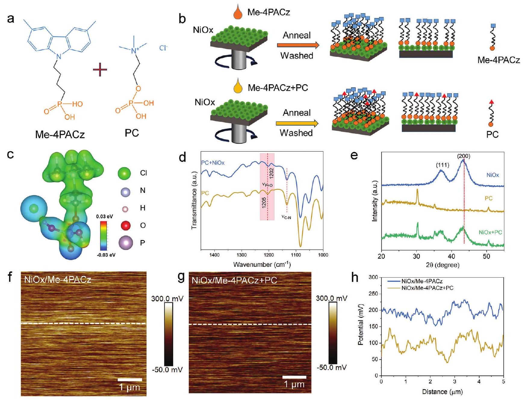
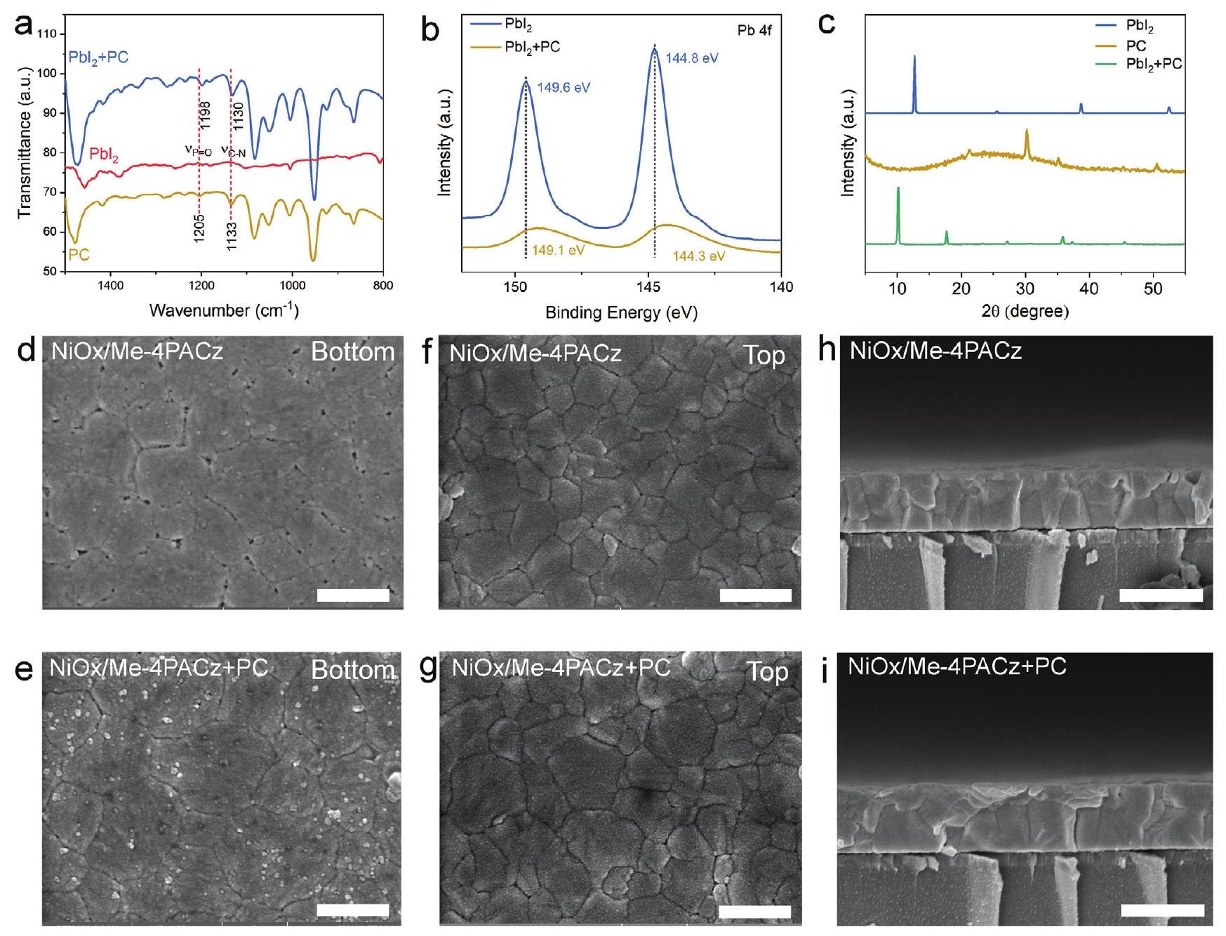
تشكل طبقة أحادية كثيفة بسبب تأثير الحواجز الستيرية، بينما يمكن لـ Co-SAM بسهولة تشكيل طبقة أحادية كثيفة وموحدة لأن PC يمكنه ملء الفراغات داخل هيكل SAM، مما يضمن تغطية أكثر اكتمالاً. مجموعات الفوسفات، أيونات الأمونيوم الرباعية، و في جزيئات الكمبيوتر تزيد أيضًا من قدرة التمرير لـ عيوب مدفونة في البيروفيسكايت. تساعد هذه التمرير المحسن في تحسين الأداء العام للجهاز. التفاعل الكيميائي بين PC في Co-SAM و تم التحقيق بشكل مكثف لاستكشاف تأثير تمرير العيوب لـ PC على السطح. للحصول على رؤى حول طبيعة هذه التفاعلات، تم إجراء حسابات غاوسيانية لتحليل الجهد الكهروستاتيكي لـ PC. تكشف الحسابات أن مجموعة الفوسفات و تظهر شخصية سالبة الشحنة، كما يتضح من لونها الأزرق، مما يشير إلى قدرتها على التبرع بالإلكترونات. من ناحية أخرى، يظهر أيون الأمونيوم الرباعي شحنة إيجابية، كما يدل على ذلك لونه الأخضر (الشكل 1c). توضح طيف الأشعة تحت الحمراء بتحويل فورييه (FTIR) أنه بعد خلط PC و لا يوجد تبديل و يخضع لانزياح أحمر قدره مقارنةً بجهاز الكمبيوتر النقي، مما يثبت أن يمكن ربطه في الكمبيوتر بـ السطح (الشكل 1د).
تحليل الطيف الإلكتروني للأشعة السينية (XPS) يكشف أن أيونات النيكل على تتحول سطح Me-4PACz إلى مستوى طاقة أقل (الشكل S1a، المعلومات الداعمة)، بينما ينتقل الأكسجين إلى مستوى طاقة أعلى بمقدار 0.55 إلكترون فولت (الشكل S1b، المعلومات الداعمة) مقارنة بالنقي. ، مما يثبت أن مجموعة الفوسفات في Me-4PACz تتفاعل مع . علاوة على ذلك، عندما يتم تقديم الكمبيوتر الشخصي إلى نظام 4 PACz )، يتم ملاحظة تحولات إضافية في مستويات الطاقة لأيونات النيكل والأكسجين. تتحول أيونات النيكل إلى مستوى طاقة أقل، بينما يتحول الأكسجين إلى مستوى طاقة أعلى بمقدار 0.09 إلكترون فولت، مما يثبت أن مجموعة الفوسفات و في الكمبيوتر التفاعل مع . بالإضافة إلى ذلك، يظهر زيادة في محتوى النيتروجين (الشكل S1c، المعلومات الداعمة) وعنصر جديد هو الكلور (الشكل S1d، المعلومات الداعمة) على السطح من ، مما يشير إلى أن و الكمبيوتر يتعايشان على الأسطح.
لتأكيد التفاعل بشكل أكبر بين في الكمبيوتر و قمنا بقياس حيود الأشعة السينية لـ ، و نمط حيود الأشعة السينية (XRD) لـ تظهر قمم واضحة لمستويات البلورة (111) و(200) (الشكل 1e). مقدمة من نتائج الكمبيوتر، يظهر انزياح أزرق لقمة (200) في حيود الأشعة السينية، مما يشير إلى توسع الشبكة البلورية. بالنظر إلى أن نصف القطر الأيوني لـ Åأكبر من Åدمج يؤدي إلى توسيع الـ هيكل الشبكة. هذه النتائج تثبت أن مجموعات الفوسفات في الطرف PC يمكن أن تتعقد مع سطح بطريقة مرتبة عمودياً. بالإضافة إلى ذلك، يمكن أيضًا أن يتم تشويهه في لقمع عيوب أيون النيكل.
لقد أخذنا في الاعتبار تأثير Co-SAM على خشونة السطح والخصائص الكهربائية لـ يمكن أن يستنتج المجهر الذري (AFM) أن خشونة سطح Me-4PACz+PC المعدل أصغر من ذلك الخاص بـ Me-4PACz (3.70 نانومتر)، مع ملف تغيير ارتفاع أكثر سلاسة (الشكل S2، المعلومات الداعمة)، مما يشير إلى أن Co-SAM يجعل الـ تساعد على تسطيح السطح وتقليل عيوب السطح. تم استخدام مجهر القوة بتقنية بروب كيلفن (KPFM) لتقييم متوسط فرق الجهد السطحي (CPD) بين و الأفلام. كما هو موضح في الشكل 1f-h، قيمة CPD لـ الفيلم أقل من ذلك فيلم. إن تقليل CPD مفيد للانخفاض في مستوى فيرمي ( ) من Me-4PACz
الفيلم، وهذه النتيجة تم إثباتها أيضًا بواسطة مطيافية الإلكترونات فوق البنفسجية (UPS). تم استخدام UPS لقياس نطاق التكافؤ (VB) و من HTL (الأشكال S3-S5، المعلومات الداعمة). الـ VB و قيم الـ فيلم هي -5.34 و -4.44 إلكترون فولت، على التوالي، بينما و من فيلم Me-4PACz+PC تنخفض إلى مستويات أدنى (VB ). VB السفلي و تكون مفيدة في تقليل حواجز نقل الثقوب وتقليل خسائر إعادة التركيب غير الإشعاعي. لقد أكدنا أيضًا تكثيف SAM أو Co-SAM على باستخدام قياسات الفولتمترية الدورية (CV). الكثافة السطحية لـ Co -SAM على هو جزيئات ، زيادة من جزيئات في SAM واحد (الشكل S6 والملاحظة S1، المعلومات الداعمة). نستنتج أن Co-SAM مفيد لتشكيل طلاء موحد وكثيف على سطح وتحسين هيكل نطاق الطاقة لطبقة SAM لتعزيز نقل الثقوب.
قمنا بإجراء FTIR وXPS وXRD لتوضيح آلية التفاعل بين PC في Co-SAM وسطح الفيلم البيروفكسيتي. تظهر طيف FTIR أنه بعد خلط PC و و تظهر انزياحًا أحمرًا لـ و ، على التوالي، مقارنةً بـ PC النقي، مما يثبت أن و يمكن أن يتفاعل في الكمبيوتر مع أيونات الرصاص على السطح السفلي المدفون للبيروفسكايت (الشكل 2أ). تظهر XPS أنه، بالنسبة لـ ، تعاني عناصر الرصاص واليود من انخفاض في الطاقة بعد خلط PC و (الشكل 2ب والشكل S7أ، المعلومات الداعمة). في الوقت نفسه، ، وتظهر N عناصر تحولًا طاقيًا تصاعديًا عند خلط PC مع مقارنةً مع الكمبيوتر الشخصي (الشكل S7b-d، المعلومات الداعمة)، مما يثبت أن مجموعات الفوسفات، وأيونات الأمونيوم الرباعية، و يمكن أن يشارك PC في تفاعلات حمض-قاعدة لويس مع Pb. تشير نتائج XRD إلى أن خلط PC مع ينتج تمامًا مرحلة مميزة مختلفة عن و PC، وهو معقد ذو أبعاد منخفضة (الشكل 2ج). بالنظر إلى تفاعل حمض الفوسفوريك مع PC إلى السطح، أيون الأمونيوم الرباعي المتبقي و تتفاعل مع عيوب الرصاص غير المتناسقة على السطح السفلي للبيروفسكايت. على وجه التحديد، أيونات الأمونيوم الرباعية، مثل أيونات التترا ميثيل أمونيوم، يمكن أن تشغل فراغات FA/MA (ميثيل أمين) داخل شبكة البيروفسكايت و قد تملأ الفراغات الخاصة بالأنيونات على سطح البيروفسكايت.
استخدمنا Co-SAM لتعديل وقمنا بدراسة تأثيره على تبلور البيروفسكايت من خلال المجهر الإلكتروني الماسح (SEM). في البداية، نستخدم الغراء فوق البنفسجي (UV) لكشف السطح السفلي للبيروفسكايت ومراقبة الشكل (الشكل 2d، e، المعلومات الداعمة). السطح السفلي لـ لديه العديد من عيوب المسام الصغيرة عند حدود الحبيبات، ولا توجد تقريبًا جزيئات صغيرة من ، مما يشير إلى أنه لا يوجد تقريبًا أي تفاعل بين Me-4PACz وسطح البيروفكسايت السفلي، بينما منطقة حدود الحبيبات على السطح السفلي من أكثر كثافة ويحتوي على العديد من الصغار الجزيئات المرتبطة. يُظهر إدخال جزيء PC تأثيرًا جسرًا، مما يعزز الالتصاق بين و film البيروفسكايت. ومن الجدير بالذكر أن حبيبات السطح السفلي لـ قد زاد بوضوح من 428 نانومتر ( ) إلى 507 نانومتر (الشكل S8a، b، المعلومات الداعمة). بعد ذلك، لاحظنا شكل السطح العلوي لفيلم البيروفسكايت. متوسط حجم الحبيبات على سطح فيلم البيروفسكايت المزروع على يصل إلى 400 نانومتر، بينما متوسط حجم الحبيبات على سطح
الشكل 2. تأثير Co-SAM على تبلور أفلام البيروفسكايت. أ) FTIR لـ PC+PbI “، و PC. ب) XPS لـ Pb 4f لـ و . ج) حيود الأشعة السينية (XRD) لـ ، و أسفل، ) السطح (مقياس الرسم 500 نانومتر)، و آراء مقطعية (مقياس الشريط 1000 نانومتر) لأفلام البيروفسكايت المودعة على طبقات نقل مختلفة.
فيلم البيروفسكايت المزروع على هو فقط 308 نانومتر (الشكل 2f، g والشكل S8c، d، المعلومات الداعمة)، مما يشير إلى أن وجود Co-SAM يسهل نمو الحبوب ويقلل العيوب في فيلم البيروفكسايت. كما تظهر صور SEM المقطعية أن الحبوب مرتبة عمودياً، مما يفيد في تعزيز نقل الحاملات (الشكل قمنا بإجراء مزيد من التحقيق في التغيرات في جودة البلورات باستخدام حيود الأشعة السينية (XRD). تظهر أفلام البيروفسكايت مع طبقات النقل المختلفة أنماط حيود مشابهة، والتي تتوافق مع اللون الأسود المميز. الطور (الشكل S9a، المعلومات الداعمة). عرض نصف الذروة لقمة (001) لفيلم البيروفسكايت على يتم العثور عليه أضيق (الشكل S9b، المعلومات الداعمة)، مما يشير إلى زيادة في حجم حبيبات البيروفسكايت، وهو ما يتماشى مع النتائج التي تم الحصول عليها من SEM. علاوة على ذلك، فإن الامتصاص المعزز في يدعم هذا البحث الفكرة المتعلقة بتحسين جودة البلورات (الشكل S10، المعلومات الداعمة). توفر هذه النتائج دليلاً على أن جزيئات Co-SAM يمكن أن تنظم عملية التبلور وتعزز زيادة حجم الحبيبات.
كركيزة لترسيب البيروفسكايت، أثرت خصائص سطح طبقة النقل العليا بشكل عميق على آليات النواة والتبلور لفيلم البيروفسكايت. لتوصيف سلوك التبلل لمحلول سلف البيروفسكايت على أسطح طبقة النقل العليا المختلفة، تم تحديد زاوية الاتصال. كانت زاوية الاتصال لمحلول سلف البيروفسكايت على تحدد HTL على أنها بينما على Me-4PACz HTL، تم العثور على زاوية الاتصال لتكون ، مما يشير إلى أن مجموعات الأمونيوم الرباعية على PC تحفز سطحًا أكثر كرهًا للماء لمذيبات السلف. للتحقيق في عملية تشكيل فيلم البيروفسكايت على أسطح HTL المختلفة، تم إجراء مطيافية الأشعة فوق البنفسجية والمرئية (UV-Vis) في الموقع أثناء عملية الطلاء الدوراني. في البداية، تكون محلول البيروفسكايت في حالة مذابة قبل 38 ثانية، مع حدوث نوى ضئيلة. عند إضافة المذيب المضاد بالتنقيط عند 38 ثانية، يبدأ شدة الامتصاص عبر نطاق الطول الموجي بالكامل في الزيادة، مما يشير إلى تشكيل بلورات البيروفسكايت. استخدمنا المشتق الأول لحساب معدل النوى بناءً على العلاقة بين 600 نانومتر ووقت الطلاء الدوراني. معدل النواة
الشكل 3. الديناميات البلورية المنظمة بواسطة Co-SAM، الإجهاد، وإعادة تركيب الحامل. أ) UV-Vis في الموقع لأفلام البيروفسكايت المودعة على أ) NiO 4PACz و ب) Me-4PACz+PC. ج) حساب معدلات النواة باستخدام المشتقات الأولى يتوافق مع طيف الأشعة فوق البنفسجية المرئية في الموقع. د) قيم المسافة بين الطبقات المستخرجة من مستوى (012) كدالة لزاوية السقوط (رسم توضيحي داخلي: مخطط للتحول من إجهاد الشد إلى إجهاد الضغط). هـ) مقارنة الإجهاد المتبقي لفيلم البيروفكسايت المودع على و . ف) طيف TRPL لأفلام البيروفسكايت المودعة على و .
من أقل لأن السطح غير القابل للرطوبة يمنع النواة غير المتجانسة، مما يؤدي إلى تقليل كثافة النواة وبالتالي زيادة حجم الحبيبات. بالإضافة إلى ذلك، التفاعل الكيميائي القوي بين PC و في البيروفسكايت يؤدي إلى تأخير في نواة البيروفسكايت، وهو ما يفيد أيضًا في الحصول على أفلام بيروفسكايت عالية البلورية بحجم حبيبات كبير.
خلال عملية تبلور أفلام البيروفسكايت (أي، التكون والنمو البلوري)، يتمثل الإجهاد الشد المتبقي ، ملاحظة 2) كان حدثًا شائعًا ومساهمًا كبيرًا في عدم الاستقرار الجوهري لخلايا الطاقة الشمسية. لتحقيق في إطلاق الإجهاد المتبقي في فيلم البيروفسكايت، تم تنفيذ قياسات حيود الأشعة السينية عند زوايا ميل مختلفة. ) (الشكل S12، المعلومات الداعمة). من خلال تحليل صور GIXRD المأخوذة من أعماق مختلفة، حصلنا على العلاقة بين المسافة بين المستويات. و ميل الـ كانت منحنى التناسب بمثابة تقدير لإطلاق الإجهاد المتبقي في فيلم البيروفسكايت (الشكل 3d). تظهر أفلام البيروفسكايت المودعة على SAM أحادي الميل إيجابي، مما يشير إلى وجود إجهاد شد داخل الأفلام. وعلى العكس، يصبح ميل الفيلم المودع على Co-SAM سالبًا قليلاً، مما يؤكد وجود إجهاد ضغط داخلي. وبالتالي، تم حساب إجهاد الشد لفيلم البيروفسكايت المودع على SAM المفرد وإجهاد الضغط للفيلم المودع على Co-SAM ليكون 41.54 و -8.09 ميغاباسكال، على التوالي (الشكل 3e). عندما تشغل أيونات الأمونيوم الرباعية الطرفية من PC الفراغات الكاتيونية العضوية على السطح السفلي المدفون للبيروفسكايت، يحدث تمدد في الشبكة بسبب
نصف القطر الأكبر لأيون الأمونيوم الرباعي ( Å ) مقارنةً بذلك من Å و Åعلاوة على ذلك، يقوم Co-SAM بضبط اتجاه البلورة وتقليل العيوب الكتلية في البيروفسكايت. قد تؤدي هذه التأثيرات إلى تغيير فيلم البيروفسكايت من إجهاد شد إلى إجهاد ضغط، مما يحسن من استقرار فيلم البيروفسكايت.
قمنا بتحليل تأثير Co-SAM على ديناميات نقل الحاملات في البيروفسكايت باستخدام الفلورية الضوئية (PL) على ركائز زجاجية. من خلال الفلورية الضوئية وقياس الفلورية الضوئية الزمنية (TRPL)، نلاحظ أن شدة الفلورية الضوئية عند الواجهة بين الـ فيلم بيروفسكايت، تم معالجته بـ ، يتم تحسينه بشكل كبير (الشكل S13، المعلومات الداعمة). بالإضافة إلى ذلك، يتم زيادة العمر الافتراضي بـ من 611 إلى 1236 نانوثانية (الشكل 3f). تشير هذه النتائج إلى أن وجود Co -SAM يثبط بشكل فعال عمليات إعادة التركيب غير الإشعاعية على الواجهة.
قمنا ببناء نموذج مقلوب نموذجي جهاز PSC القائم على – وحققنا في تأثير Co-SAM على أدائه الكهروضوئي. في دراستنا، وجدنا أن PC يعزز من قدرة تمرير العيوب لـ في واجهة فيلم البيروفسكايت، كما هو موضح في الشكل 4a. أداء الأجهزة المعدلة بتركيزات مختلفة من أو الكمبيوتر الشخصي موضح في الأشكال S14-S16 (المعلومات الداعمة). كلاهما مي-4PACz أو كمبيوتر معدل يمكن أن يكون له تأثيرات مفيدة، لكن مزيج Me-4PACz و PC يظهر أداءً متفوقًا. نحن نحقق أيضًا في معلمات وفقرات الخلايا الشمسية المعدلة بتركيزات مختلفة من PC المخلوط بـ Me-4PACz، كما هو موضح في الشكل 4b. تم تحديد تركيز التعديل الأمثل ليكون .
الشكل 4. تأثير Co-SAM على كفاءة تحويل الطاقة للجهاز. أ) مخطط هيكلي لبنية الجهاز المقلوبة ودور التفاعل لـ Co-SAM مع وأفلام البيروفسكايت. ب) تأثير Me-4PACz المدعوم بتركيزات مختلفة من PC على أداء الجهاز. ج) أداء المسح الأمامي والعكسي لـ -تم إيداع أجهزة Me-4PACz و Me-4PACz+PC. د) EQE و هـ) أداء الخرج الثابت لـ NiO أجهزة الكمبيوتر.
بعد ذلك، كانت أعلى قيمة PCE للمجموعة الضابطة و Me-4PACz + يتم قياس الجهاز المعدل بواسطة الكمبيوتر خلال المسحات الأمامية والخلفية. في المسح الخلفي، يظهر الجهاز المعالج بتقنية Co-SAM زيادة في كفاءة تحويل الطاقة من إلى زيادة في من 1.153 إلى 1.175 فولت، زيادة في كثافة تيار القصر ) من 25.32 إلى وزيادة في عامل التعبئة (FF) من إلى . في المسح الأمامي، يزيد PCE للجهاز المعالج بـ Co-SAM من إلى (الشكل 4c). تم تقليل عامل الهسترس (HF، ملاحظة S3، المعلومات الداعمة) لعينة Co-SAM المعالجة، ويرجع ذلك أساسًا إلى تثبيط التمرير وتعزيز نقل الحامل الذي تلعبه PC عند الواجهة. الجهاز المعالج بـ Co-SAM يحقق تيارًا متكاملًا قدره من خلال طيف الكفاءة الكمية الخارجية (EQE) (الشكل 4d) وكفاءة الإخراج الثابتة (SPO) لـ (الشكل 4e)، وكلاهما قريب من النتائج التي تم الحصول عليها بواسطة المنحنى. الشكل S17 (المعلومات الداعمة) يظهر مخطط إحصائيات معلمات الخلايا الشمسية. متوسط كفاءة تحويل الطاقة (PCE) للجهاز المعالج بـ Co-SAM يزيد من إلى ، مع انحراف معياري مخفض، مما يدل على تحسين القابلية للتكرار. للتحقق من عمومية استراتيجية Co-SAM، نستخدم O-fosfo-di-serine و creatinol phosphate المدعمة بـ Me-4PACz، بالإضافة إلى الأجهزة المعالجة بـ 2PACz المدعمة بـ PC، مما يؤدي إلى كفاءات من ، ، و على التوالي (الأشكال S18-S20، المعلومات الداعمة)، مما يثبت أن التعديل الجزيئي البسيط يمكن أن يحسن أداء SAM.
استخدمنا طريقة موت-شوتكي للتحقق من تعزيز الـ يظهر الجهاز المعالج بـ Co-SAM مجالًا كهربائيًا مدمجًا بقيمة 1.16 فولت، متجاوزًا القيمة البالغة 1.11 فولت التي لوحظت في
الجهاز المعالج بواسطة SAM الوحيد. هذه الزيادة في المجال الكهربائي مفيدة لتسهيل نقل الشحنات وتحسين في الأجهزة الكهروضوئية (الشكل 5أ). EQE قيم من و يمكن الحصول على ذلك لجهاز SAM وجهاز Co-SAM المعالج، على التوالي، من طيف الإضاءة الكهروضوئية (EL) (الشكل 5b). النسبة العالية نسبيًا تشير القيمة إلى أن Co-SAM، كعامل تعديل واجهي، يمكن أن يخفف فقدان ناتج عن إعادة التركيب غير الإشعاعي. بالإضافة إلى ذلك، مبلغ التحسين ( ، ملاحظة S4، المعلومات الداعمة) بعد علاج Co-SAM يُقدّر أن يكون 0.021 فولت، وهو تقريبًا متسق مع الفرق (0.022 فولت) الذي تم الحصول عليه بواسطة
علاج Co-SAM يحسن جودة البلورات في فيلم البيروفسكايت ويساعد في تحسين الجهاز. للتحقيق في استجابة الجهاز، أجرينا تجارب لتحليل العلاقة بين الـ وشدة الضوء المطبق (الشكل 5c والملاحظة S5، المعلومات الداعمة). يظهر الجهاز الضابط عامل مثالية ( ) من 1.52 ، في حين أن الجهاز المعالج بـ Co-SAM يظهر انخفاضًا ملحوظًا في قيمة 1.12. من المعروف أن يعكس إعادة التركيب المعتمدة على العيوب في الأجهزة، وتؤكد هذه النتيجة بشكل أكبر أن إعادة التركيب عند الواجهة في الأجهزة المعالجة بـ Co-SAM قد تم تقليلها بشكل كبير، مما يساعد على تحسين معامل الملء للجهاز.
للاستكشاف كمية العيوب وحركة الثقوب في الجهاز، تم إجراء قياس التيار المحدود بالشحنة الفضائية (SCLC). كما هو موضح في الشكل 5d، يمثل تقاطع المنطقة الأومية ومنطقة ملء الفخاخ جهد حد ملء الفخاخ. )، والتي تم تحديدها لتكون 1.25 فولت و 0.87 فولت لـ وأجهزة معالجة Co-SAM، على التوالي، مع العيب المقابل
الشكل 5. ديناميات الحاملات والاستقرار. أ) تحليل موت-شوتكي. ب) قيم الـ PSCs. ج) اعتماد شدة الضوء على من خلايا الطاقة الشمسية. د) SCLC للأجهزة ذات الفتحة فقط. هـ) منحنيات tDOS لأجهزة PSC التي تستخدم و . و) تدهور إشارة التبييض لأفلام البيروفسكايت. ز) منحنيات J-V في الظلام لخلايا الطاقة الشمسية ذات الركائز المختلفة. ح) SPO لخلايا الطاقة الشمسية المغلفة المقاسة عند MPP تحت إضاءة شمسية مستمرة.
كثافات الحالة لـ و (ملاحظة S6، المعلومات الداعمة). اعتمادًا على منطقة SCLC، فإن حركة الثقوب هي 6.18 و لـ وأجهزة معالجة Co-SAM (انظر S6، المعلومات الداعمة). هذه النتائج تثبت أن Co-SAM يمكن أن يقلل من عيوب الأجهزة ويسرع من نقل الثقوب. علاوة على ذلك، لتحديد نوع عيب الجهاز، قمنا بإجراء اختبار طيف القبول (الشكل 5e والملاحظة S7، المعلومات الداعمة). مقارنةً بـ SAM الفردي، فإن الأجهزة المعالجة بـ Co-SAM تقلل من كل من العيوب في مستويات الطاقة العميقة والسطحية (عيوب السطح وحدود الحبوب)، مما يظهر أن Co-SAM ينظم تبلور البيروفسكايت، ويعزز جودة البلورة للبيروفسكايت، ويقلل من حدود الحبوب وعيوب السطح في فيلم البيروفسكايت.
تم استخدام مطيافية الامتصاص العابر في الفيمتوثانية لتحليل ديناميات الحاملات في أفلام البيروفسكايت المودعة على SAM مفرد و Co-SAM (الشكل S21، المعلومات الداعمة). يمكن ملاحظة أن معدل تلاشي الحالة الأساسية لفيلم البيروفسكايت المودع على Co-SAM قد زاد بشكل ملحوظ. وعمر الازدواجية الأسية
تم تقليل النموذج الحركي في الوقت نفسه، مما يؤكد مرة أخرى أن Co-SAM يمكن أن يعزز نقل الحامل (الشكل 5f). بالإضافة إلى ذلك، فإن التغطية الأفضل لـ Co-SAM على الركيزة تقلل بشكل فعال من تيار التسرب، مما يوضح بشكل أكبر التأثير المفيد لـ Co-SAM في تحسين أداء الجهاز (الشكل 5g).
تم تقييم الاستقرار التشغيلي للأجهزة المغلفة تحت تتبع نقطة القدرة القصوى (MPP) والتعرض لمصباح ثنائي باعث للضوء (LED) بنفس شدة ضوء الشمس (بدون فلتر للأشعة فوق البنفسجية) في الهواء المحيط عند درجة حرارة . في الشكل 5h، يمكن ملاحظة أن جهاز التحكم، بكفاءة أولية من ، يظهر تدهورًا نسبيًا سريعًا، محتفظًا فقط بحوالي من PCE الأولية لها بعد 1000 ساعة. وفقًا لمبدأ التوهين الخطي، يحتفظ الجهاز المعالج بطريقة SAM الواحدة قيمته الأولية لفترة ممتدة من . بالمقابل، يظهر الجهاز المعالج بعلاج Co-SAM تدهورًا أبطأ في الأداء بعد 1000 ساعة من التشغيل المستمر. يحتفظ بحوالي من PCE الأولية الخاصة به ( ” ). التقدير وقت لـ
الجهاز المعالج بـ Co-SAM هو يعزز علاج Co-SAM بشكل كبير الاستقرار التشغيلي للأجهزة الشمسية المحاطة، بشكل رئيسي من خلال قمع عيوب الجهاز واستقرار بلورات البيروفسكايت.

3. الخاتمة

باختصار، نستخدم PC مع Me-4PACz لتشكيل CoSAM على سطح لتحسين الواجهة المدفونة في PSC. مجموعة الفوسفات و في الكمبيوتر يمكن أن يثبط عيوب السطح. في هذه الأثناء، أيونات الأمونيوم الرباعية و يمكن أن تملأ الكاتيونات العضوية وعيوب الفراغات الهالوجينية في الجزء السفلي من فيلم البيروفسكايت. يمكن أن تعزز Co-SAM نمو بلورات البيروفسكايت، وتخمد العيوب المدفونة، وتثبط إعادة التركيب غير الإشعاعي، وتحسن محاذاة نطاق الطاقة لتسهيل نقل الحاملات، وتخفف من الضغط المتبقي لفيلم البيروفسكايت. ونتيجة لذلك، يتم تعزيز متوسط كفاءة الجهاز بشكل كبير من إلى بكفاءة بطولية تبلغ . علاوة على ذلك، يمكن للجهاز الاحتفاظ بـ القيمة الأولية بعد التشغيل المستمر لمدة 1000 ساعة تحت إضاءة الشمس الواحدة. تُظهر هذه الدراسة مزايا تعديل Co -SAM على HTL في خلايا الشمسية.

المعلومات الداعمة

المعلومات الداعمة متاحة من مكتبة وايلي على الإنترنت أو من المؤلف.

شكر وتقدير

تم دعم هذا البحث من قبل المؤسسة الوطنية للعلوم الطبيعية في الصين (22305 191)، وتمويل مشروع البحث لما بعد الدكتوراه في مقاطعة شانشي، وبرنامج العلماء في هونغ كونغ (XJ2022025)، ومجلس منح الأبحاث (RGC) في هونغ كونغ، الصين (رقم المشروع 15306822)، وجامعة بوليتكنك هونغ كونغ، هونغ كونغ، الصين (ZE2X).

تعارض المصالح

يعلن المؤلفون عدم وجود أي تضارب في المصالح.

بيان توفر البيانات

البيانات التي تدعم نتائج هذه الدراسة متاحة من المؤلف المراسل عند الطلب المعقول.

الكلمات المفتاحية

واجهة مدفونة، خلايا شمسية من البيروفسكايت المقلوبة، طبقة أحادية ذاتية التجميع
تاريخ الاستلام: 11 نوفمبر 2023
تمت المراجعة: 15 ديسمبر 2023
نُشر على الإنترنت: 15 يناير 2024
[2] ز. لي، إكس. صن، إكس. تشنغ، ب. لي، د. قاو، س. تشانغ، إكس. وو، س. لي، ج. قونغ، ج. م. لوثر، ز. لي، ز. تشو، ساينس 2023، 382، 284.
[3] ف. ما، ي. تشاو، ج. لي، إكس. تشانغ، هـ. غو، ج. يو، مجلة الكيمياء الطاقية 2021، 52، 393.
[4] ز.-و. قاو، ي. وانغ، و. س. هـ. تشوي، مواد الطاقة المتقدمة 2022، 12، 2104030.
[5] سي. سي. بوايد، آر. سي. شالكروس، تي. موت، آر. كيرنر، إل. بيرتولوزي، آ. أونو، إس. كافاديا، سي. تشوسي، إي. ج. وولف، جي. ويرنر، جي. آ. ريفورد، سي. دي باولا، آ. ف. بالمستروم، زي. ج. يو، جي. جي. بيري، إس. ف. بينت، زي. سي. هولمان، جي. إم. لوثر، إي. إل. راتكليف، إن. آر. أرمسترونغ، إم. دي. مكغيهي، جول 2020، 4، 1759.
[6] و. تشين، ي. زو، ج. تشين، ي. وو، ب. تو، ف.-ز. ليو، ل. هوانغ، أ. م. سي. نج، أ. ب. دجوريسيك، ز. هي، مواد الطاقة المتقدمة 2019، 9، 1803872.
[7] X. Zhu، C. F. J. Lau، K. Mo، S. Cheng، Y. Xu، R. Li، C. Wang، Q. Zheng، Y. Liu، T. Wang، Q. Lin، Z. Wang، Nano Energy 2022، 103، 107849.
[8] C. Li, X. Wang, E. Bi, F. Jiang, S. M. Park, Y. Li, L. Chen, Z. Wang, L. Zeng, H. Chen, Y. Liu, C. R. Grice, A. Abudulimu, J. Chung, Y. Xian, T. Zhu, H. Lai, B. Chen, R. J. Ellingson, F. Fu, D. S. Ginger, Z. Song, E. H. Sargent, Y. Yan, Science 2023, 379, 690.
[9] ت. وانغ، ف. تشنغ، ج. تانغ، ج. كاو، ب. يو، ج. تشاو، ف. يان، أدف. ساي. 2021، 8، 2004315.
[10] ل. لي، ي. وانغ، إكس. وانغ، ر. لين، إكس. لو، ز. ليو، ك. تشو، س. شيونغ، ق. باو، ج. تشين، ي. تيان، ي. دينغ، ك. شياو، ج. وو، م. إ. سعيدامينوف، هـ. لين، س.-ك. ما، ز. تشاو، ي. وو، ل. تشانغ، هـ. تان، نات. إنرجي 2022، 7، 708.
[11] ي. هوانغ، ب. وانغ، ت. ليو، د. لي، ي. تشانغ، ت. تشانغ، إكس. ياو، ي. وانغ، أ. أميني، ي. كاي، ب. شو، ز. تانغ، ج. شينغ، س. تشينغ، مواد متقدمة وظيفية 2023، 33، 2302375.
[12] ر. هي، و. وانغ، ز. يي، ف. لانغ، ج. تشين، ج. لو، ج. تشو، ج. ثيسبروميل، س. شاه، ك. وي، ي. لو، ج. وانغ، هـ. لاي، هـ. هوانغ، ج. تشو، ب. زو، إكس. يين، س. رين، إكس. هاو، ل. وو، ج. تشانغ، ج. تشانغ، م. ستولترفوهت، ف. فو، و. تانغ، د. تشاو، ناتشر 2023، 618، 80.
[13] س. تشانغ، ف. يي، إكس. وانغ، ر. تشين، هـ. تشانغ، ل. زهان، إكس. جيانغ، ي. لي، إكس. جي، س. ليو، م. يو، ف. يو، ي. تشانغ، ر. وو، ز. ليو، ز. نينغ، د. نهر، ل. هان، ي. لين، هـ. تيان، و. تشين، م. ستولترفوهت، ل. تشانغ، و.-هـ. تشو، ي. وو، ساينس 2023، 380، 404.
[14] ل. ماو، ت. يانغ، هـ. تشانغ، ج. شي، ي. هو، ب. زينغ، ف. لي، ج. قونغ، إكس. فانغ، ي. صن، إكس. ليو، ج. دو، أ. هان، ل. تشانغ، و. ليو، ف. منغ، إكس. كوي، ز. ليو، م. ليو، مواد متقدمة 2022، 34، 2206193.
[15] ق. جيانغ، ر. تيروات، ر. أ. كيرنر، إ. أ. غولدينغ، ي. شيان، إكس. وانغ، ج. م. نيوكيرك، ي. يان، ج. ج. بيري، ك. زو، ناتشر 2023، 623، 313.
[16] ب. نيو، هـ. ليو، ي. هوانغ، إ. غو، م. يان، ز. شين، ك. يان، ب. يان، ج. ياو، ي. فانغ، هـ. تشين، س.-ز. لي، مواد متقدمة 2023، 35، 2212258.
[17] I. كافيدجيسكا، I. ليفين، A. موسيينكو، N. ماتيتشوك، T. بيرترام، A. العشوري، C. A. كاوفمان، S. ألبريخت، R. شلاتمان، I. لاورمان، Adv. Funct. Mater. 2023، 33، 2302924.
[18] ج. تاو، إكس. ليو، ج. شين، س. هان، ل. جوان، ج. فو، د.-ب. كوانغ، س. يانغ، ACS نانو 2022، 16، 10798.
[19] ل. يانغ، هـ. زو، ي. دوآن، م. وو، ك. هي، ي. لي، د. شو، هـ. زو، س. يانغ، ز. فانغ، س. ليو، ز. ليو، مواد متقدمة 2023، 35، 2211545.
[20] د. تشانغ، إكس. وانغ، تي. تيان، إكس. شيا، ج. دوآن، ز. فان، ف. لي، مجلة الهندسة الكيميائية 2023، 469، 143789.
[21] م. ليو، ل. بي، و. جيانغ، ز. زينغ، س.-و. تسونغ، ف. ر. لين، أ. ك.-ي. جين، مواد متقدمة 2023، 2304415.
[22] س. م. بارك، م. وي، ن. لمبسي، و. يو، ت. حسيني، ل. أغوستا، ف. كارنيفالي، هـ. ر. أتاباتو، ب. سيرلز، ف. ت. إيكيماير، هـ. شين، م. فافاي، د. تشوي، ك. دارابي، إ. د. جونغ، ي. يانغ، د. ب. كيم، س. م. زاكير الدين، ب. تشين، أ. أماسسيان، ت. فيليتر، م. ج. كاناتزيديس، ك. ر. غراهام، ل. شياو، أ. روثليسبيرغر، م. غراتزل، إ. هـ. سارجنت، ناتشر 2023، 624، 289.
[23] س. يانغ، ي. وانغ، ب. ليو، ي.-ب. تشينغ، هـ. ج. تشاو، هـ. ج. يانغ، نات. إنرجي 2016، 1، 15016.
[24] ق. تشو، ج. تشيو، ر. زوانغ، م. يو، ج. ليو، ي. هوا، ل. دينغ، إكس. تشانغ، مواد واجهات ACS التطبيقية 2023، 15، 40676.
[25] سي. ليو، ل. هوانغ، إكس. تشو، إكس. وانغ، ج. ياو، ز. ليو، س. ف. ليو، و. ما، ب. شو، مجلة العلوم 2021، 66، 1419.
[26] ق. تشاو، ي. لي، ي. تشانغ، ج. تشاو، ت. وانغ، ب. يانغ، إكس. بو، ج. يانغ، هـ. تشين، إكس. تشين، إكس. لي، س. غاسمي، هـ. سالاري، أ. هاغفيلدت، إكس. لي، مواد الطاقة المتقدمة 2022، 12، 2201435.
[27] ق. ليانغ، ك. ليو، م. صن، ز. رين، ب. و. ك. فونغ، ج. هوانغ، م. كوين، ز. وو، د. شين، ج.-س. لي، ج. هاو، إكس. لو، ب. هوانغ، ج. لي، مواد متقدمة 2022، 34، 2200276.
[28] C. بي، Q. وانغ، Y. شاو، Y. يوان، Z. شياو، J. هوانغ، نات. كوميونيك. 2015، 6، 7747.
[29] ن. وو، ت. يانغ، ز. وانغ، ي. وو، ي. وانغ، ج. ما، هـ. لي، ي. دو، د. تشاو، س. وانغ، ب. ليو، و. هوانغ، إكس. رين، س. ف. ليو، ك. تشاو، مواد متقدمة 2023، 35، 2304809.
[30] هـ. زانغ، ن.-ج. بارك، أنجيو. كيم.، إنت. إد. 2022، 61، 202212268.
[31] ب. يانغ، د. بوجاتشوك، ج. سُو، ل. فاغنر، هـ. كيم، ج. ليم، أ. هينش، ج. بوشلو، م. ك. نازير الدين، أ. هاجفيلدت، مراجعات الجمعية الكيميائية 2022، 51، 7509.
[32] ن. رولستون، ك. أ. بوش، أ. د. برينتس، أ. غولد-باركر، ي. دينغ، م. ف. توني، م. د. مكغي، ر. هـ. داوسكاردت، مواد الطاقة المتقدمة 2018، 8، 1802139.
[33] هـ. زانغ، ز. تشين، م. كوين، ز. رين، ك. ليو، ج. هوانغ، د. شين، ز. وو، ي. زانغ، ج. هاو، س.-ش. لي، إكس. لو، ز. تشنغ، و. يو، ج. لي، مواد متقدمة 2021، 33، 2008487.
[34] إكس. تشانغ، ج.-إكس. تشونغ، س. لي، ك. ياو، ي. فانغ، ج. يانغ، ي. تان، ك. شيو، ل. كيو، ك. وانغ، ي. بينغ، و.-كيو. وو، أنجيو. كيم.، إنت. إد. 2023، 62، 202309292.
[35] هـ. وي، ي. يانغ، س. تشين، هـ. ج. شيانغ، نات. كوميونيك. 2021، 12، 637.
[36] م. سليب، ت. ماتسوي، ك. دومانسكي، ج.-ي. سيو، أ. أوماديسينغو، س. م. زاكير الدين، ج.-ب. كوريا-باينا، و. ر. تريس، أ. أباتي، أ. هاجفيلدت، م. غراتزل، ساينس 2016، 354، 206.
[37] C.-C. Zhang، S. Yuan، Y.-H. Lou، Q.-W. Liu، M. Li، H. Okada، Z.-K. Wang، Adv. Mater. 2020، 32، 2001479.
[38] ج. يانغ، ت. وانغ، ي. لي، إكس. بو، هـ. تشين، ي. لي، ب. يانغ، ي. تشانغ، ج. تشاو، ق. كاو، إكس. تشين، س. غاسمي، أ. هاغفيلدت، إكس. لي، سول. آر. آر. إل 2022، 6، 2200422.
[39] ت. وانغ، ي. لي، ق. قاو، ج. يانغ، ب. يانغ، إكس. بو، ي. تشانغ، ج. تشاو، ي. تشانغ، هـ. تشين، أ. هاجفيلدت، إكس. لي، علوم الطاقة والبيئة 2022، 15، 4414.
[40] ز. لي، ب. لي، إكس. وو، س. أ. شيفارد، س. زانغ، د. قاو، ن. ج. لونغ، ز. زو، ساينس 2022، 376، 416.
[41] ق. جيانغ، ي. تشاو، إكس. تشانغ، إكس. يانغ، ي. تشين، ز. تشو، ق. يي، إكس. لي، ز. يين، ج. يو، نات. فوتونيكس 2019، 13، 460.
[42] ق. كاو، ي. تشانغ، إكس. بو، ج. تشاو، ت. وانغ، ك. تشانغ، هـ. تشن، إكس. هي، ج. يانغ، س. تشانغ، إكس. لي، ج. كيمياء الطاقة 2023، 86، 9.
[43] هـ. تشينغ، س. ليو، ج. زوانغ، ج. كاو، ت. وانغ، و.-ي. وونغ، ف. يان، مواد متقدمة وظيفية 2022، 32، 2204880.
[44] هـ. تشين، ج. يانغ، ق. كاو، ت. وانغ، إكس. بو، إكس. هي، إكس. تشين، إكس. لي، طاقة نانو 2023، 117، 108883.
[45] ق. تشاو، ج. يانغ، ت. وانغ، ي. لي، إكس. بو، ج. تشاو، ي. تشانغ، هـ. تشو، إكس. لي، إكس. لي، علوم الطاقة والبيئة 2021، 14، 5406.
[46] X. Pu، J. Zhao، Y. Li، Y. Zhang، H.-L. Loi، T. Wang، H. Chen، X. He، J. Yang، X. Ma، X. Li، Q. Cao، Nano Energy 2023، 112، 108506.
[47] ر. تشين، ج. وانغ، ز. ليو، ف. رين، س. ليو، ج. تشو، هـ. وانغ، إكس. مينغ، ز. تشانغ، إكس. جوان، و. ليانغ، ب. أ. تروشن، ي. تشي، ل. هان، و. تشين، نات. إنرجي 2023، 8، 839.
[48] X. Deng, F. Qi, F. Li, S. Wu, F. R. Lin, Z. Zhang, Z. Guan, Z. Yang, C.-S. Lee, A. K.-Y. Jen, أنجيو. كيم., إنت. إد. 2022, 61, 202203088.
[49] ج. زوانغ، ج. وانغ، ف. يان، رسائل نانو-ميكرو. 2023، 15، 84.
[50] ب. شي، ي. دينغ، ب. دينغ، ق. شينغ، ت. كودالي، ج. م. سوتير-فيلا، إ. يافوز، ج. ياو، و. فان، ج. شيو، ي. تيان، د. غو، ك. تشاو، س. تان، إكس. تشانغ، ل. ياو، ب. ج. دايسون، ج. ل. سلاك، د. يانغ، ج. شيو، م. ك. نازير الدين، ي. يانغ، ر. وانغ، ناتشر 2023، 620، 323.

  1. ق. كاو، ت. وانغ، م. شياو، ل. زوانغ، ق. وي، هـ.-ل. لوئي، ب. كانغ، ج. زوانغ، ج. فنغ، ف. يان
    قسم الفيزياء التطبيقية
    جامعة بوليتكنك هونغ كونغ
    هونغ هوم، كولون، منطقة هونغ كونغ الإدارية الخاصة 999077، جمهورية الصين الشعبية
    البريد الإلكتروني: apafyan@polyu.edu.hk
    يمكن العثور على رقم التعريف ORCID للمؤلفين في هذه المقالة تحتhttps://doi.org/10.1002/adma. 202311970
    © 2024 المؤلف(ون). المواد المتقدمة نشرتها وايلي-فيتش GmbH. هذه مقالة مفتوحة الوصول بموجب شروط ترخيص المشاع الإبداعي للنسب، الذي يسمح بالاستخدام والتوزيع وإعادة الإنتاج في أي وسيلة، بشرط أن يتم الاستشهاد بالعمل الأصلي بشكل صحيح.
    ق. تشاو، إكس. بو، إكس. هي، إتش. تشين، بي. قوه، جي. فنغ، إكس. لي
    المختبر الوطني الرئيسي لمعالجة التصلب
    مركز مواد الطاقة النانوية
    كلية علوم المواد والهندسة
    جامعة شمال غرب بوليتكنيك
    شيان 710072، جمهورية الصين الشعبية
    البريد الإلكتروني: lixh32@nwpu.edu.cn
  2. [1] هـ. زانغ، ج. تشاو، ج. ياو، و. س. هـ. تشوي، أنجيو. كيم.، إنت. إد. 2023، 62، 202219307.

Journal: Advanced Materials, Volume: 36, Issue: 16
DOI: https://doi.org/10.1002/adma.202311970
PMID: https://pubmed.ncbi.nlm.nih.gov/38198824
Publication Date: 2024-01-11

Co-Self-Assembled Monolayers Modified for Stable Inverted Perovskite Solar Cells

Qi Cao, Tianyue Wang, Xingyu Pu, Xilai He, Mingchao Xiao, Hui Chen, Lvchao Zhuang, Qi Wei, Hok-Leung Loi, Peng Guo, Bochun Kang, Guangpeng Feng, Jing Zhuang, Guitao Feng, Xuanhua Li,* and Feng Yan*

Abstract

[4-(3,6-dimethyl-9H-carbazol-9yl)butyl]phosphonic acid (Me-4PACz) self-assembled molecules (SAM) are an effective method to solve the problem of the buried interface of in inverted perovskite solar cells (PSCs). However, the Me-4PACz end group (carbazole core) cannot forcefully passivate defects at the bottom of the perovskite film. Here, a Co-SAM strategy is employed to modify the buried interface of PSCs. Me-4PACz is doped with phosphorylcholine chloride (PC) to form a Co-SAM to improve the monolayer coverage and reduce leakage current. The phosphate group and chloride ions in PC can inhibit surface defects. Meantime, the quaternary ammonium ions and in PC can fill organic cations and halogen vacancies in the perovskite film to enable defects passivation. Moreover, Co-SAM can promote the growth of perovskite crystals, collaboratively solve the problem of buried defects, suppress nonradiative recombination, accelerate carrier transmission, and relieve the residual stress of the perovskite film. Consequently, the Co-SAM modified devices show power conversion efficiencies as high as as well as excellent device stability with initial efficiency after 1000 h of operation under one-sun illumination. This work demonstrates the novel approach for enhancing the performance and stability of PSCs by modifying Co-SAM on .

of However, there is still room for improvement as the highest authenticated PCE stands at . The presence of oxygen vacancies and uncoordinated metal ion defects on the surface contributes to this potential for enhancement. Additionally, submicronscale defects exist on the lower surface of the perovskite material. The interaction between and the perovskite film also leads to interface reactions, resulting in nonradiative recombination at the interface. These phenomena adversely affect device stability and cause a loss of opencircuit voltage ( ), which poses a significant obstacle to achieving high-efficiency and highly stable inverted PSCs. Therefore, addressing these issues is crucial for advancing the performance of inverted PSCs.
To address the interface problem in perovskite heterojunctions, various strategies have been employed, such as the use of inorganic salts, selfassembled monolayers (SAMs), organic molecules, and 2D materials, to modify and passivate the buried interface. Li et al.

1. Introduction

, an inorganic p-type semiconductor, is commonly utilized as the hole transport layer (HTL) in inverted and tandem perovskite solar cells (PSCs) due to its cost-effectiveness, stability, and scalability. Notably, the -inverted PSC has recently achieved a certified power conversion efficiency (PCE) successfully improved the interface by utilizing SAM-processed nanocrystals, which effectively bridged the perovskite film. This approach created a hole-selective contact that mitigated interface recombination and facilitated hole extraction. As a result, they achieved a remarkable efficiency of (certified as ) in a flexible all-perovskite tandem solar cell. In a similar vein, Huang et al. employed
Figure 1. Effect of Co-SAM on properties. a) Molecular structures of Me-4PACz and PC. b) Schematic illustration of SAM (Me-4PACz) and Co-SAM (Me-4PACz+PC) of modified . c) Gaussian calculated electrostatic potential of PC molecule. d) FTIR of PC+NiO and PC. e) XRD of NiO , PC, and PC . KPFM images of f) Me-4PACz and g) PC. h) CPD changes of and films .
[4-(3,6-dimethyl-9H-carbazol-9yl)butyl]phosphonic acid (Me4PACz) to address interface defects in the formamidinium lead triiodide junction. By reducing these defects and improving carrier transport, they achieved an PCE of in an inverted .based PSCs. Researchers have continued to refine the design of SAMs, leading to significant advancements in the development of high-performance photovoltaic devices. SAMs composed of carbazole core and phosphonic acid, such as 2PACz ([2-(9H-Carbazol-9-yl)ethyl]phosphonic acid) and Me-4PACz, are particularly prevalent due to their maturity in industrial applications. However, despite the widespread use of these SAMs, there are certain limitations that need to be addressed. The steric hindrance of the carbazole core restricts the formation of a dense single molecule layer on the substrate, hampering effective passivation of bottom defects in the perovskite film. Consequently, this can lead to issues such as leakage current and nonradiative recombination, adversely affecting the performance and stability of optoelectronic devices.
Here, we modify the buried interface of -based PSCs by doping Me-4PACz with phosphorylcholine chloride (PC) to form Co-SAM (Figure 1a) for improving the monolayer coverage. The phosphate group and chloride ions in PC can inhibit surface defects. Meantime, the quaternary ammonium ions and in PC can fill organic cations and halogen vacancies defects at the bottom of the perovskite film. Co-SAM can promote the growth of perovskite crystals, collaboratively solve the problem of buried defects, suppress nonradiative recombination, accelerate carrier transmission, and relieve the residual stress of the perovskite film. Therefore, the maximum efficiency of the Co-SAM modified device reaches . And the operational stability of the device is improved, maintaining of the initial efficiency after continuous running for 1000 h under one-sun illumination.

2. Results and Discussion

To highlight the advantages of Co-SAM, we drew a schematic diagram in Figure 1b. Spin-coating of SAM alone on cannot
form a dense monolayer due to the steric hindrance effect, while Co-SAM easily forms a dense and uniform single monolayer because PC can fill the vacancies within the SAM structure, ensuring more complete coverage. The phosphate groups, quaternary ammonium ions, and in the PC molecules also increase the passivation ability of /perovskite buried defects. This improved passivation helps improve the overall performance of the device. The chemical interaction between PC in Co-SAM and was extensively investigated to explore the defect passivation effect of PC on the surface. To gain insights into the nature of these interactions, Gaussian calculations were performed to analyze the electrostatic potential of PC. The calculation reveals that the phosphate group and exhibit a negatively charged character, indicated by their blue color, suggesting their ability to donate electrons. On the other hand, the quaternary ammonium ion displays a positive charge, as denoted by its green color (Figure 1c). Fourier transform infrared (FTIR) spectra demonstrate that after mixing PC and has no shift and undergoes a red shift of compared to pure PC, proving that in PC can be chelated to the surface (Figure 1d).
X-ray photoelectron spectroscopy (XPS) reveals that Ni ions on the Me-4PACz surface shift to a lower energy level (Figure S1a, Supporting Information), and O shifts to a higher energy level by 0.55 eV (Figure S1b, Supporting Information) than pure , proving that the phosphate group in Me-4PACz interacts with . Furthermore, when PC is introduced to the 4 PACz system ( ), additional shifts in the energy levels of Ni and O ions are observed. Ni ions further shift to a lower energy level and O shifts to a higher energy level by 0.09 eV , proving that the phosphate group and in PC interact with . Additionally, an increase in N content (Figure S1c, Supporting Information) and the new element Cl (Figure S1d, Supporting Information) appear on the surface of , indicating that and PC coexist on surfaces.
To further confirm the interaction between in PC and , we measured the XRD of , and . The XRD pattern of exhibits prominent (111) and (200) crystal plane peaks (Figure 1e). The introduction of from PC results a blue shift of the (200) XRD peak, indicating lattice expansion. Considering that the ionic radius of is larger than , the incorporation of leads to the expansion of the lattice structure. These results prove that PC-terminal phosphate groups can be chelated to the surface in a vertically arranged manner. In addition, can also be doped into to suppress Ni ion defects.
We considered the impact of Co-SAM on the surface roughness and electrical properties of . Atomic force microscopy (AFM) can conclude that the surface roughness of Me-4PACz+PC-modified is smaller than that of Me-4PACz ( 3.70 nm ), with a smoother height change profile (Figure S2, Supporting Information), indicating that Co-SAM makes the surface flatter and helps reduce surface defects. Kelvin probe force microscopy (KPFM) was employed to evaluate the average surface contact potential difference (CPD) between and films. As shown in Figure 1f-h, the CPD value of film is lower than that of film. The reduction of CPD is beneficial to the downward shift of the Fermi level ( ) of Me-4PACz
film, and this result is also proved by Ultraviolet photoelectron spectroscopy (UPS). UPS was employed to measure the valence band (VB) and of HTL (Figures S3-S5, Supporting Information). The VB and values of the film are -5.34 and -4.44 eV , respectively, while the and of the Me-4PACz+PC film decrease to lower levels (VB ). The lower VB and are beneficial to reducing hole transfer barriers and decreasing nonradiative recombination losses. We further confirmed the densification of SAM or Co -SAM on using cyclic voltammetry (CV) measurements. The areal density of Co -SAM on is molecules , an increase from molecules in single SAM (Figure S6 and Note S1, Supporting Information). We conclude that Co-SAM is beneficial to forming a uniform and dense coating on the surface and optimizing the energy band structure of the SAM layer to enhance hole transport.
We conducted FTIR, XPS, and XRD to elucidate the interaction mechanism between PC in Co-SAM and the bottom surface of the perovskite film. The FTIR spectra show that after mixing PC and and exhibit a red shift of and , respectively, compared to pure PC , proving that and in PC can interact with Pb ions on the buried bottom surface of perovskite (Figure 2a). XPS shows that, relative to , the Pb and I elements experience a downward energy shift after mixing PC and (Figure 2b and Figure S7a, Supporting Information). Simultaneously, the , and N elements exhibit an upward energy shift when PC is mixed with compared with PC (Figure S7b-d, Supporting Information), proving that the phosphate groups, quaternary ammonium ions, and in PC can engage in Lewis acid-base interactions with Pb . XRD results indicate that mixing PC with completely produces a distinct phase different from and PC, which is a low-dimensional complex (Figure 2c). Considering the chelation of phosphoric acid in PC to the surface, the remaining quaternary ammonium ion and interact with the uncoordinated Pb defects on the bottom surface of the perovskite. Specifically, the quaternary ammonium ions, like tetra-methyl ammonium ions, can occupy the FA/MA (methylamine) vacancies within the perovskite lattice and may fill the vacancies of anions on the perovskite surface.
We utilized Co -SAM to modify and investigated its effect on perovskite crystallization through scanning electron microscopy (SEM). Initially, we use ultraviolet (UV) glue to uncover the bottom surface of the perovskite and observe the morphology (Figure 2d,e, Supporting Information). The bottom surface of has many small pore defects at the grain boundary, and there are almost no small particles of , indicating that there is almost no interaction between Me-4PACz and the bottom surface of perovskite, while the grain boundary area on the bottom surface of is denser and has many small particles attached. The introduction of PC molecule exhibits a bridging effect, enhancing the adhesion between and the perovskite film. Notably, the bottom surface grains of has obviously increased from 428 nm ( ) to 507 nm (Figure S8a,b, Supporting Information). Next, we observed the morphology of the upper surface of the perovskite film. The mean grain size on the surface of the perovskite film grown on reaches 400 nm , while the mean grain size on the surface of
Figure 2. Effect of Co-SAM on crystallization of perovskite films. a) FTIR of PC+PbI , and PC. b) XPS of Pb 4 f for and . c) XRD of , and ) Bottom, ) surface (the scale bar is 500 nm ), and ) cross-sectional views (the scale bar is 1000 nm ) of perovskite films deposited on different transport layers.
the perovskite film grown on is only 308 nm (Figure 2f,g and Figure S8c,d, Supporting Information), indicating that the presence of Co-SAM facilitates promote grain growth and reduce defects in the perovskite film. The crosssectional SEM images also present that the grains are vertically arranged, which is beneficial to promoting carrier transport (Figure . We conducted further investigation on the changes in crystal quality using XRD. Perovskite films with different transport layers exhibit similar diffraction patterns, which consistent with the characteristic black phase (Figure S9a, Supporting Information). The half-peak width of the (001) peak of the perovskite film on is found to be narrower (Figure S9b, Supporting Information), indicating an increase in the perovskite grain size, which aligns with the results obtained from SEM. Moreover, the enhanced absorption in the band further supports the notion of improved crystal quality (Figure S10, Supporting Information). These findings provide evidence that Co -SAM molecules can regulate crystallization and promote the increase in grain size.
As the substrate for perovskite deposition, the surface properties of the HTL profoundly affected the nucleation and crystallization mechanisms of perovskite film. To characterize the wetting behavior of the perovskite precursor solution on the different HTL surface, the contact angle was determined. The contact angle of the perovskite precursor solution on HTL is determined to be , while on Me-4PACz HTL, the contact angle is found to be , indicating that the quaternary ammonium groups on PC induce a more hydrophobic surface for precursor solvents (Figure S11, Supporting Information). To investigate the perovskite film formation process on different HTL surfaces, in situ UV-visible (UV-Vis) spectroscopy was performed during spin-coating (Figure 3a,b). Initially, the perovskite precursor solution is in a dissolved state before 38 s, with negligible nucleation occurring. Upon the dropwise addition of the antisolvent at 38 s , the absorption intensity across the entire wavelength range starts to increase, indicating the formation of perovskite crystallites. We used the first derivative to calculate the nucleation rate based on the relationship between 600 nm and spin-coating time (Figure 3c). The nucleation rate
Figure 3. Co-SAM-regulated crystallization kinetics, strain, and carrier recombination. a) In situ UV-Vis of perovskite films deposited on a) NiO 4PACz and b) Me-4PACz+PC. c) Calculation of nucleation rates using first derivatives corresponds to in situ UV-Vis spectra. d) D-spacing values obtained from (012) plane as a function of incidence angle (interior illustration: schematic of the transformation from tensile stress to compressive stress). e) Comparison of residual stress for perovskite film deposited on and . f) TRPL spectra of perovskite films deposited on and .
of is lower because the nonwetting surface inhibits heterogeneous nucleation, resulting in a reduction in nucleation density and thus a larger grain size. In addition, the strong chemical interaction between PC and in the perovskite leads to a delay in perovskite nucleation, which is also beneficial to obtain highly crystalline perovskite films with large grain sizes.
During the crystallization process of perovskite films (i.e., nucleation and crystal growth), residual tensile stress ( , note 2 ) was a common occurrence and a significant contributor to the intrinsic instability of PSCs. To investigate the release of residual stress in the perovskite film, grazing incidence X-ray diffraction (GIXRD) measurements were implemented at different tilt angles ( ) (Figure S12, Supporting Information). Through analysis of the GIXRD images acquired at different depths, we obtained the relationship between the interplanar distance and . The slope of the fitting curve served as an estimation of the residual stress release in the perovskite film (Figure 3d). Perovskite films deposited on single SAM exhibit positive slopes, indicating the presence of tensile stress within the films. Conversely, the slope of the film deposited on Co-SAM becomes slightly negative, confirming the presence of internal compressive stress. Consequently, the tensile stress of the perovskite film deposited on single SAM and the compressive stress of the film deposited on Co-SAM are calculated to be 41.54 and -8.09 MPa , respectively (Figure 3e). When the organic cation vacancies on the buried bottom surface of the perovskite are occupied by the terminal quaternary ammonium ions of PC, the lattice undergoes expansion due to
the larger radius of the quaternary ammonium ion ( ) compared to that of the and Moreover, Co-SAM adjusts the crystal orientation and reduces bulk defects of perovskite. These effects may cause the perovskite film to change from tensile stress to compressive stress, improving the stability of the perovskite film.
We analyzed the influence of Co-SAM on perovskite carrier transport dynamics using photoluminescence (PL) on glass substrates. Through PL and time-resolved PL (TRPL) spectroscopy, we observe that the PL intensity at the interface between the perovskite film, treated with , is significantly enhanced (Figure S13, Supporting Information). Additionally, the lifetime is increased by , from 611 to 1236 ns (Figure 3f). These findings indicate that the presence of Co -SAM effectively suppresses interfacial nonradiative recombination processes.
We constructed a typical inverted -based PSC device and investigated the impact of Co-SAM on its photovoltaic performance. In our study, we found that PC enhances the defect passivation ability of at the perovskite film interface, as depicted in Figure 4a. The performance of devices modified with different concentrations of or PC is shown in Figures S14-S16 (Supporting Information). Both Me-4PACz or PC modified can have beneficial effects, but the combination of Me-4PACz and PC demonstrates superior performance. We further investigate the photovoltaic parameters and curves of devices modified with different concentrations of PC doped with Me-4PACz, as shown in Figure 4b. The optimal doping concentration is determined to be .
Figure 4. Impact of Co-SAM on device PCE. a) Schematic diagram of the inverted device structure and the interaction role of Co-SAM with and perovskite films. b) Effect of Me-4PACz doped with different concentrations of PC on device performance. c) The forward and reverse scanning performance of -deposited Me-4PACz and Me-4PACz+PC devices. d) EQE and e) steady-state output performance of NiO PC devices .
Subsequently, the highest PCE of the control and Me-4PACz + PC modified device is measured during forward and reverse scans. In reverse scan, the Co-SAM-treated device exhibits an increase in PCE from to , an increase in from 1.153 to 1.175 V , an increase in short-circuit current density ( ) from 25.32 to , and an increase in fill factor (FF) from to . In forward scan, the PCE of the Co-SAM-treated device increases from to (Figure 4c). The hysteresis factor (HF, Note S3, Supporting Information) of Co-SAM-treated is reduced, mainly due to the passivation inhibition and promotion of carrier transport played by PC at the interface. The Co-SAM-treated device achieves an integrated current of through external quantum efficiency (EQE) spectra (Figure 4d) and a steady-state output (SPO) efficiency of (Figure 4e), both of which are close to the results obtained by the curve. Figure S17 (Supporting Information) shows the photovoltaic parameter statistics chart. The average PCE of the device treated with Co-SAM increases from to , with a reduced standard deviation, demonstrating improved repeatability. To verify the universality of the Co-SAM strategy, we employ O-phospho-di-serineand creatinol phosphate-doped Me-4PACz, as well as PC-doped 2PACz-treated devices, which result in efficiencies of , , and , respectively (Figures S18-S20, Supporting Information), proving that simple molecular doping can improve the performance of SAM.
We used the Mott-Schottky method to validate the enhancement of the . The Co-SAM-treated device exhibits a built-in electric field of 1.16 V , surpassing the value of 1.11 V observed in
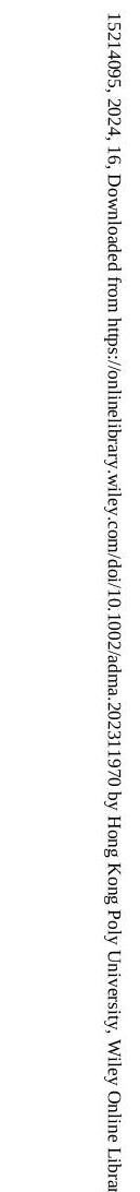
the single SAM-treated device. This enhancement in the electric field is advantageous for facilitating charge transport and improving the in photovoltaic devices (Figure 5a). The EQE values of and for the SAM and the Co-SAM-treated device, respectively, can be obtained from the electroluminescence (EL) spectra (Figure 5b). The relatively high value indicates that Co-SAM, as an interfacial modifier, can suppress loss caused by nonradiative recombination. In addition, the improvement amount ( , Note S4, Supporting Information) after Co-SAM treatment is estimated to be 0.021 V , which is almost consistent with the difference ( 0.022 V ) obtained by
Co-SAM treatment improves the crystal quality of the perovskite film and helps improve the of the device. To investigate the device’s response, we conducted experiments to analyze the relationship between the and the applied light intensity (Figure 5c and Note S5, Supporting Information). The control device shows an ideality factor ( ) of 1.52 , whereas the Co-SAMtreated device demonstrates a significantly lower value of 1.12. It is known that the reflects defect-assisted recombination in devices, and this result further confirms that interfacial recombination in Co-SAM-treated devices has been substantially suppressed, helping to improve the FF of the device.
To explore the amount of defect and hole mobility in the device, space charge limited current (SCLC) was performed. As depicted in Figure 5d, the intersection of the ohmic region and the trap-filling region represents the trap filling limit voltage ( ), which is determined to be 1.25 V and 0.87 V for and Co-SAM treated devices, respectively, with corresponding defect
Figure 5. Carrier dynamics and stability. a) Mott-Schottky analysis. b) values of the PSCs. c) Light intensity dependence of of PSCs. d) SCLC of the hole-only devices. e) tDOS curves of PSC devices employing and . f) Decay of the bleaching signal of perovskite films. g) Dark J-V curves of PSCs with different substrates. h) SPO of the encapsulated PSCs measured at MPP under continuous one-sun illumination.
state densities of and (Note S6, Supporting Information). Depending on the SCLC region, the hole mobility is 6.18 and for and Co-SAM treated devices (Note S6, Supporting Information). These results prove that Co-SAM can suppress device defects and accelerate hole transport. Furthermore, to determine the type of device defect, we conducted an admittance spectrum test (Figure 5e and Note S7, Supporting Information). Compared with single SAM, Co-SAM-treated devices reduce both deep and shallow energy level defects (surface and grain boundary defects), which shows that Co-SAM regulates perovskite crystallization, promotes better crystallinity of perovskite, and reduces the grain boundaries and surface defects of the perovskite film.
Femtosecond transient absorption spectroscopy was further used to analyze the carrier dynamics in perovskite films deposited on single SAM and Co-SAM (Figure S21, Supporting Information). It can be seen that the ground-state bleaching decay rate of the perovskite film deposited on Co -SAM is significantly enhanced, and the lifetime of the double-exponential
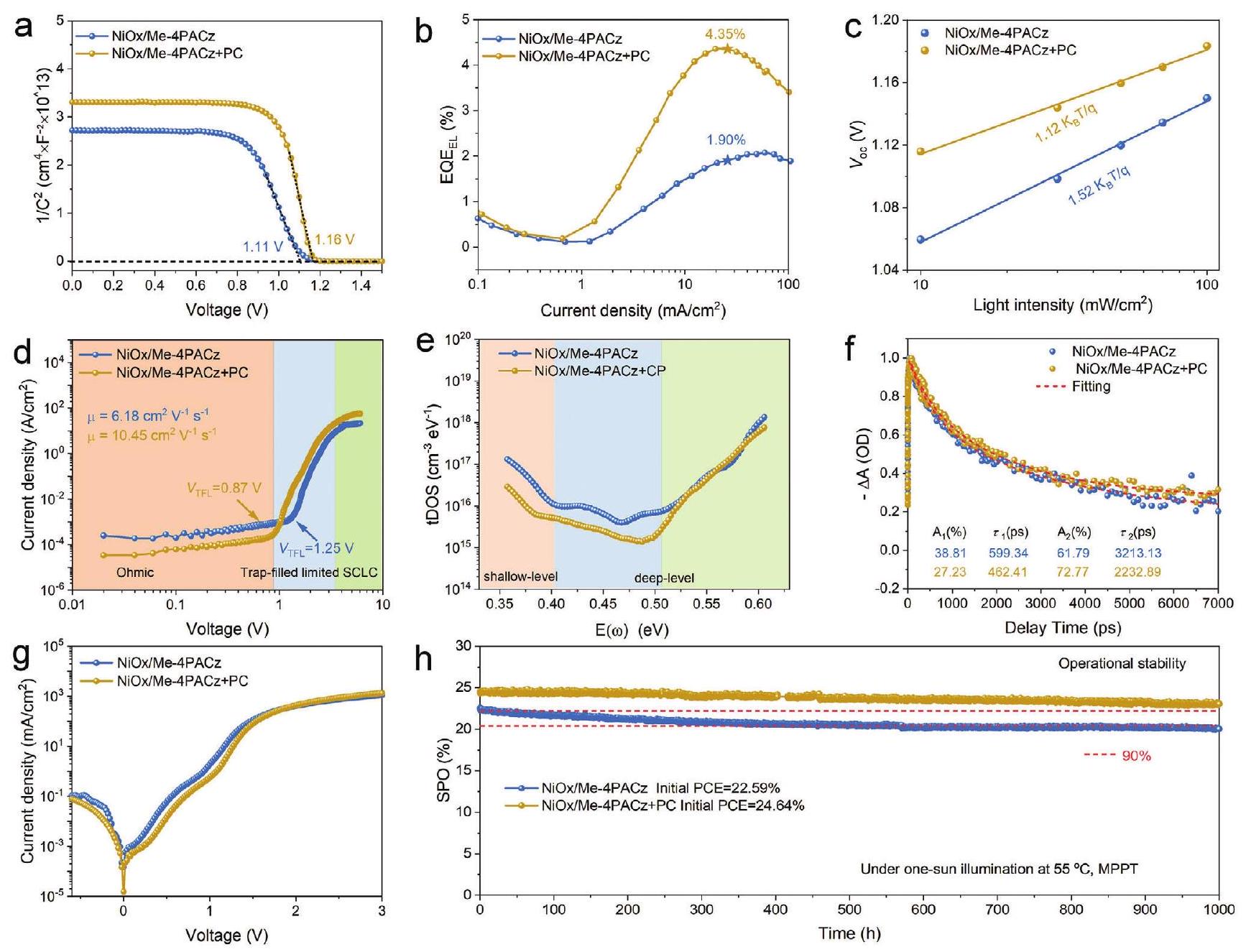
kinetic model is simultaneously reduced, which once again verifies that Co-SAM can promote carrier transport (Figure 5f). Additionally, the better coverage of Co-SAM on the substrate effectively reduces the leakage current, further demonstrating the beneficial effect of Co-SAM in optimizing device performance (Figure 5g).
The operational stability of the encapsulated devices was evaluated under maximum power point (MPP) tracking and exposure to a white light-emitting diode (LED) lamp with the same intensity as one-sunlight (without UV filter) in ambient air at a temperature of . In Figure 5h, it can be observed that the control device, with an initial efficiency of , exhibits relatively rapid degradation, retaining only about of its initial PCE after 1000 h . According to the principle of linear attenuation, the single SAM-treated device retains of its initial value for an extended duration of . In contrast, the device treated with a Co-SAM treatment shows slower decay in performance after 1000 h of continuous running. It retains about of its initial PCE ( ). The estimated time for the
Co-SAM-treated device is . The Co-SAM treatment significantly improves the operational stability of the encapsulated PSCs, mainly by suppressing device defects and stabilizing the perovskite crystals.

3. Conclusion

In summary, we use PC together with Me-4PACz to form CoSAM on surface to optimize the buried interface in PSC. The phosphate group and in PC can inhibit surface defects. Meantime, the quaternary ammonium ions and in PC can fill organic cations and halogen vacancies defects at the bottom of the perovskite film. Co-SAM can promote the growth of perovskite crystals, passivate buried defects, suppress nonradiative recombination, optimize the energy band alignment to facilitate carrier transmission, and relieve the residual stress of the perovskite film. As a result, the average device PCE is substantially enhanced from to with a champion efficiency of . Moreover, the device can retain of the initial value after continuous running for 1000 h under one-sun illumination. This work demonstrates the advantages of modifying Co -SAM on HTL in PSCs.

Supporting Information

Supporting Information is available from the Wiley Online Library or from the author.

Acknowledgements

This research was supported by the National Natural Science Foundation of China (22305 191), Postdoctoral Research Project Funding in Shaanxi Province, the Hong Kong Scholars Program (XJ2022025), the Research Grants Council (RGC) of Hong Kong, China (Project No. 15306822), and the Hong Kong Polytechnic University, Hong Kong, China (ZE2X).

Conflict of Interest

The authors declare no conflict of interest.

Data Availability Statement

The data that support the findings of this study are available from the corresponding author upon reasonable request.

Keywords

buried interface, inverted perovskite solar cells, self-assembled monolayer
Received: November 11, 2023
Revised: December 15, 2023
Published online: January 15, 2024
[2] Z. Li, X. Sun, X. Zheng, B. Li, D. Gao, S. Zhang, X. Wu, S. Li, J. Gong, J. M. Luther, Z. Li, Z. Zhu, Science 2023, 382, 284.
[3] F. Ma, Y. Zhao, J. Li, X. Zhang, H. Gu, J. You, J. Energy Chem. 2021, 52, 393.
[4] Z.-W. Gao, Y. Wang, W. C. H. Choy, Adv. Energy Mater. 2022, 12, 2104030.
[5] C. C. Boyd, R. C. Shallcross, T. Moot, R. Kerner, L. Bertoluzzi, A. Onno, S. Kavadiya, C. Chosy, E. J. Wolf, J. Werner, J. A. Raiford, C. De Paula, A. F. Palmstrom, Z. J. Yu, J. J. Berry, S. F. Bent, Z. C. Holman, J. M. Luther, E. L. Ratcliff, N. R. Armstrong, M. D. Mcgehee, Joule 2020, 4, 1759.
[6] W. Chen, Y. Zhou, G. Chen, Y. Wu, B. Tu, F.-Z. Liu, L. Huang, A. M. C. Ng, A. B. Djurisic, Z. He, Adv. Energy Mater. 2019, 9, 1803872.
[7] X. Zhu, C. F. J. Lau, K. Mo, S. Cheng, Y. Xu, R. Li, C. Wang, Q. Zheng, Y. Liu, T. Wang, Q. Lin, Z. Wang, Nano Energy 2022, 103, 107849.
[8] C. Li, X. Wang, E. Bi, F. Jiang, S. M. Park, Y. Li, L. Chen, Z. Wang, L. Zeng, H. Chen, Y. Liu, C. R. Grice, A. Abudulimu, J. Chung, Y. Xian, T. Zhu, H. Lai, B. Chen, R. J. Ellingson, F. Fu, D. S. Ginger, Z. Song, E. H. Sargent, Y. Yan, Science 2023, 379, 690.
[9] T. Wang, F. Zheng, G. Tang, J. Cao, P. You, J. Zhao, F. Yan, Adv. Sci. 2021, 8, 2004315.
[10] L. Li, Y. Wang, X. Wang, R. Lin, X. Luo, Z. Liu, K. Zhou, S. Xiong, Q. Bao, G. Chen, Y. Tian, Y. Deng, K. Xiao, J. Wu, M. I. Saidaminov, H. Lin, C.-Q. Ma, Z. Zhao, Y. Wu, L. Zhang, H. Tan, Nat. Energy 2022, 7, 708.
[11] Y. Huang, B. Wang, T. Liu, D. Li, Y. Zhang, T. Zhang, X. Yao, Y. Wang, A. Amini, Y. Cai, B. Xu, Z. Tang, G. Xing, C. Cheng, Adv. Funct. Mater. 2023, 33, 2302375.
[12] R. He, W. Wang, Z. Yi, F. Lang, C. Chen, J. Luo, J. Zhu, J. Thiesbrummel, S. Shah, K. Wei, Y. Luo, C. Wang, H. Lai, H. Huang, J. Zhou, B. Zou, X. Yin, S. Ren, X. Hao, L. Wu, J. Zhang, J. Zhang, M. Stolterfoht, F. Fu, W. Tang, D. Zhao, Nature 2023, 618, 80.
[13] S. Zhang, F. Ye, X. Wang, R. Chen, H. Zhang, L. Zhan, X. Jiang, Y. Li, X. Ji, S. Liu, M. Yu, F. Yu, Y. Zhang, R. Wu, Z. Liu, Z. Ning, D. Neher, L. Han, Y. Lin, H. Tian, W. Chen, M. Stolterfoht, L. Zhang, W.-H. Zhu, Y. Wu, Science 2023, 380, 404.
[14] L. Mao, T. Yang, H. Zhang, J. Shi, Y. Hu, P. Zeng, F. Li, J. Gong, X. Fang, Y. Sun, X. Liu, J. Du, A. Han, L. Zhang, W. Liu, F. Meng, X. Cui, Z. Liu, M. Liu, Adv. Mater. 2022, 34, 2206193.
[15] Q. Jiang, R. Tirawat, R. A. Kerner, E. A. Gaulding, Y. Xian, X. Wang, J. M. Newkirk, Y. Yan, J. J. Berry, K. Zhu, Nature 2023, 623, 313.
[16] B. Niu, H. Liu, Y. Huang, E. Gu, M. Yan, Z. Shen, K. Yan, B. Yan, J. Yao, Y. Fang, H. Chen, C.-Z. Li, Adv. Mater. 2023, 35, 2212258.
[17] I. Kafedjiska, I. Levine, A. Musiienko, N. Maticiuc, T. Bertram, A. AlAshouri, C. A. Kaufmann, S. Albrecht, R. Schlatmann, I. Lauermann, Adv. Funct. Mater. 2023, 33, 2302924.
[18] J. Tao, X. Liu, J. Shen, S. Han, L. Guan, G. Fu, D.-B. Kuang, S. Yang, ACS Nano 2022, 16, 10798.
[19] L. Yang, H. Zhou, Y. Duan, M. Wu, K. He, Y. Li, D. Xu, H. Zou, S. Yang, Z. Fang, S. Liu, Z. Liu, Adv. Mater. 2023, 35, 2211545.
[20] D. Zhang, X. Wang, T. Tian, X. Xia, J. Duan, Z. Fan, F. Li, Chem. Eng. J. 2023, 469, 143789.
[21] M. Liu, L. Bi, W. Jiang, Z. Zeng, S.-W. Tsang, F. R. Lin, A. K.-Y. Jen, Adv. Mater. 2023, 2304415.
[22] S. M. Park, M. Wei, N. Lempesis, W. Yu, T. Hossain, L. Agosta, V. Carnevali, H. R. Atapattu, P. Serles, F. T. Eickemeyer, H. Shin, M. Vafaie, D. Choi, K. Darabi, E. D. Jung, Y. Yang, D. B. Kim, S. M. Zakeeruddin, B. Chen, A. Amassian, T. Filleter, M. G. Kanatzidis, K. R. Graham, L. Xiao, U. Rothlisberger, M. Grätzel, E. H. Sargent, Nature 2023, 624, 289.
[23] S. Yang, Y. Wang, P. Liu, Y.-B. Cheng, H. J. Zhao, H. G. Yang, Nat. Energy 2016, 1, 15016.
[24] Q. Zhou, J. Qiu, R. Zhuang, M. Yu, J. Liu, Y. Hua, L. Ding, X. Zhang, ACS Appl. Mater. Interfaces 2023, 15, 40676.
[25] C. Liu, L. Huang, X. Zhou, X. Wang, J. Yao, Z. Liu, S. F. Liu, W. Ma, B. Xu, Sci. Bull. 2021, 66, 1419.
[26] Q. Cao, Y. Li, Y. Zhang, J. Zhao, T. Wang, B. Yang, X. Pu, J. Yang, H. Chen, X. Chen, X. Li, S. Ghasemi, H. Salari, A. Hagfeldt, X. Li, Adv. Energy Mater. 2022, 12, 2201435.
[27] Q. Liang, K. Liu, M. Sun, Z. Ren, P. W. K. Fong, J. Huang, M. Qin, Z. Wu, D. Shen, C.-S. Lee, J. Hao, X. Lu, B. Huang, G. Li, Adv. Mater. 2022, 34, 2200276.
[28] C. Bi, Q. Wang, Y. Shao, Y. Yuan, Z. Xiao, J. Huang, Nat. Commun. 2015, 6, 7747.
[29] N. Wu, T. Yang, Z. Wang, Y. Wu, Y. Wang, C. Ma, H. Li, Y. Du, D. Zhao, S. Wang, P. Liu, W. Huang, X. Ren, S. F. Liu, K. Zhao, Adv. Mater. 2023, 35, 2304809.
[30] H. Zhang, N.-G. Park, Angew. Chem., Int. Ed. 2022, 61, 202212268.
[31] B. Yang, D. Bogachuk, J. Suo, L. Wagner, H. Kim, J. Lim, A. Hinsch, G. Boschloo, M. K. Nazeeruddin, A. Hagfeldt, Chem. Soc. Rev. 2022, 51, 7509.
[32] N. Rolston, K. A. Bush, A. D. Printz, A. Gold-Parker, Y. Ding, M. F. Toney, M. D. Mcgehee, R. H. Dauskardt, Adv. Energy Mater. 2018, 8, 1802139.
[33] H. Zhang, Z. Chen, M. Qin, Z. Ren, K. Liu, J. Huang, D. Shen, Z. Wu, Y. Zhang, J. Hao, C.-S. Lee, X. Lu, Z. Zheng, W. Yu, G. Li, Adv. Mater. 2021, 33, 2008487.
[34] X. Chang, J.-X. Zhong, S. Li, Q. Yao, Y. Fang, G. Yang, Y. Tan, Q. Xue, L. Qiu, Q. Wang, Y. Peng, W.-Q. Wu, Angew. Chem., Int. Ed. 2023, 62, 202309292.
[35] H. Wei, Y. Yang, S. Chen, H. J. Xiang, Nat. Commun. 2021, 12, 637.
[36] M. Saliba, T. Matsui, K. Domanski, J.-Y. Seo, A. Ummadisingu, S. M. Zakeeruddin, J.-P. Correa-Baena, W. R. Tress, A. Abate, A. Hagfeldt, M. Grätzel, Science 2016, 354, 206.
[37] C.-C. Zhang, S. Yuan, Y.-H. Lou, Q.-W. Liu, M. Li, H. Okada, Z.-K. Wang, Adv. Mater. 2020, 32, 2001479.
[38] J. Yang, T. Wang, Y. Li, X. Pu, H. Chen, Y. Li, B. Yang, Y. Zhang, J. Zhao, Q. Cao, X. Chen, S. Ghasemi, A. Hagfeldt, X. Li, Sol. RRL 2022, 6, 2200422.
[39] T. Wang, Y. Li, Q. Cao, J. Yang, B. Yang, X. Pu, Y. Zhang, J. Zhao, Y. Zhang, H. Chen, A. Hagfeldt, X. Li, Energy Environ. Sci. 2022, 15, 4414.
[40] Z. Li, B. Li, X. Wu, S. A. Sheppard, S. Zhang, D. Gao, N. J. Long, Z. Zhu, Science 2022, 376, 416.
[41] Q. Jiang, Y. Zhao, X. Zhang, X. Yang, Y. Chen, Z. Chu, Q. Ye, X. Li, Z. Yin, J. You, Nat. Photonics 2019, 13, 460.
[42] Q. Cao, Y. Zhang, X. Pu, J. Zhao, T. Wang, K. Zhang, H. Chen, X. He, J. Yang, C. Zhang, X. Li, J. Energy Chem. 2023, 86, 9.
[43] H. Cheng, C. Liu, J. Zhuang, J. Cao, T. Wang, W.-Y. Wong, F. Yan, Adv. Funct. Mater. 2022, 32, 2204880.
[44] H. Chen, J. Yang, Q. Cao, T. Wang, X. Pu, X. He, X. Chen, X. Li, Nano Energy 2023, 117, 108883.
[45] Q. Cao, J. Yang, T. Wang, Y. Li, X. Pu, J. Zhao, Y. Zhang, H. Zhou, X. Li, X. Li, Energy Environ. Sci. 2021, 14, 5406.
[46] X. Pu, J. Zhao, Y. Li, Y. Zhang, H.-L. Loi, T. Wang, H. Chen, X. He, J. Yang, X. Ma, X. Li, Q. Cao, Nano Energy 2023, 112, 108506.
[47] R. Chen, J. Wang, Z. Liu, F. Ren, S. Liu, J. Zhou, H. Wang, X. Meng, Z. Zhang, X. Guan, W. Liang, P. A. Troshin, Y. Qi, L. Han, W. Chen, Nat. Energy 2023, 8, 839.
[48] X. Deng, F. Qi, F. Li, S. Wu, F. R. Lin, Z. Zhang, Z. Guan, Z. Yang, C.-S. Lee, A. K.-Y. Jen, Angew. Chem., Int. Ed. 2022, 61, 202203088.
[49] J. Zhuang, J. Wang, F. Yan, Nano-Micro Lett. 2023, 15, 84.
[50] P. Shi, Y. Ding, B. Ding, Q. Xing, T. Kodalle, C. M. Sutter-Fella, I. Yavuz, C. Yao, W. Fan, J. Xu, Y. Tian, D. Gu, K. Zhao, S. Tan, X. Zhang, L. Yao, P. J. Dyson, J. L. Slack, D. Yang, J. Xue, M. K. Nazeeruddin, Y. Yang, R. Wang, Nature 2023, 620, 323.

  1. Q. Cao, T. Wang, M. Xiao, L. Zhuang, Q. Wei, H.-L. Loi, B. Kang, J. Zhuang, G. Feng, F. Yan
    Department of Applied Physics
    The Hong Kong Polytechnic University
    Hung Hom, Kowloon, Hong Kong SAR 999077, P. R. China
    E-mail: apafyan@polyu.edu.hk
    The ORCID identification number(s) for the author(s) of this article can be found under https://doi.org/10.1002/adma. 202311970
    © 2024 The Author(s). Advanced Materials published by Wiley-VCH GmbH. This is an open access article under the terms of the Creative Commons Attribution License, which permits use, distribution and reproduction in any medium, provided the original work is properly cited.
    Q. Cao, X. Pu, X. He, H. Chen, P. Guo, G. Feng, X. Li
    State Key Laboratory of Solidification Processing
    Center for Nano Energy Materials
    School of Materials Science and Engineering
    Northwestern Polytechnical University
    Xi’an 710072, P. R. China
    E-mail: lixh32@nwpu.edu.cn
  2. [1] H. Zhang, C. Zhao, J. Yao, W. C. H. Choy, Angew. Chem., Int. Ed. 2023, 62, 202219307.