إبر ميكرونية حلزونية مزدوجة الطبقة مدعومة بالاهتزازات الدقيقة لاستخراج سائل الأنسجة الجلدية بسرعة للكشف عن الجلوكوز بطريقة minimally invasive Micro-vibration assisted dual-layer spiral microneedles to rapidly extract dermal interstitial fluid for minimally invasive detection of glucose

المجلة: Microsystems & Nanoengineering، المجلد: 11، العدد: 1
DOI: https://doi.org/10.1038/s41378-024-00850-x
PMID: https://pubmed.ncbi.nlm.nih.gov/39774609
تاريخ النشر: 2025-01-08

إبر ميكرونية حلزونية مزدوجة الطبقة مدعومة بالاهتزازات الدقيقة لاستخراج سائل الأنسجة الجلدية بسرعة للكشف عن الجلوكوز بطريقة minimally invasive

خالد محمد سيف الله عاصم مشتاق بوريا أزارخاه فيليب د. بريفيت غراهام ج. دافيز وزهرة فرجي راد®

الملخص

تم استكشاف هيدروجيلات متنوعة لإنشاء إبر دقيقة (MNs) minimally invasive لاستخراج السائل بين الأنسجة (ISF). ومع ذلك، فإن الطرق الحالية تستغرق وقتًا طويلاً وعادة ما تتطلب لاستخراج من السائل بين الأنسجة (ISF). تقدم هذه الدراسة مجموعتين من الإبر الدقيقة القابلة للتورم على شكل لولبي: واحدة مصنوعة من ميثاكريلات الجيلاتين (GelMA) وبولي فينيل الكحول (PVA)، والأخرى تضم مزيجًا من PVA وبولي فينيل بيروليدون (PVP) وحمض الهيالورونيك (HA) لاستخراج ISF بسرعة. أظهرت هذه المجموعات من الإبر الدقيقة نسبة تورم سريعة من و في ISF الاصطناعي خلال 10 دقائق، على التوالي. بالإضافة إلى ذلك، تقترح هذه الدراسة طريقة جديدة تجمع بين MNs مع جهاز تطبيق مصمم خصيصًا يعتمد على Arduino ويهتز في نطاقات ترددات لتحسين كفاءة اختراق الجلد، مما يعزز امتصاص السائل بين الأنسجة في الظروف الخارجية. هذه التركيبة الديناميكية تمكن إبر GeIMA/PVA الدقيقة من امتصاص سريع من ISF في 5 دقائق فقط، بينما يتم استخراج MNs من PVA/PVP/HA من ISF ضمن نفس الإطار الزمني. للتحقق من قدرة MNs على استعادة الجلوكوز كعلامة حيوية مستهدفة، يتم استخدام إجراء تسخين خفيف، يليه تحديد تركيز الجلوكوز باستخدام مجموعة اختبار محتوى d-glucose. تشير الكفاءة في استخراج ISF وقدرات الكشف عن الجلوكوز لمسام MNs الحلزونية إلى إمكانياتها في الكشف السريع وغير الجراحي عن العلامات الحيوية.

مقدمة

أدى الحاجة إلى تقنيات الحد الأدنى من التدخل إلى تقدم كبير في استخراج سوائل الجسم وارتباطها بأخذ عينات الدم والتشخيصات عند نقطة الرعاية. بينما يُعتبر اختبار الدم هو المعيار الذهبي في التشخيص لتقييم مختلف معايير الصحة واكتشاف حالات طبية متنوعة، فإنه يواجه تحديات مثل التدخل الجراحي ومخاطر العدوى. قد يكون أيضًا غير متاح في البيئات ذات الموارد المحدودة. بالإضافة إلى ذلك، فإن إمكانيات سوائل الجسم الأخرى مثل اللعاب والبول والعرق محدودة بسبب تركيزات منخفضة إلى معدومة من المؤشرات الحيوية. .
السائل بين الأنسجة هو سائل عديم اللون يشبه الماء ويقع في الفراغات بين الأوعية الدموية والخلايا. يلعب دورًا حاسمًا في نظام نقل المغذيات، حيث ينقل المحللات والمغذيات والفضلات بعيدًا عن الشعيرات الدموية عبر الانتشار. البلازما في الدم تحتوي على عوامل التخثر التي تبدأ في تشكيل الجلطة عند حدوث إصابة، مما يمنع النزيف المفرط. المصل هو في الأساس بلازما بدون هذه عوامل التخثر ويتم الحصول عليه من بلازما الدم عن طريق السماح للدم بالتخثر ثم إزالة الجلطة الناتجة. على عكس البلازما والمصل، لا يحتوي السائل بين الخلايا على أي عوامل تخثر، وبسبب ذلك، فإنه لا يتخثر. . هذه سمة مهمة لأن التجلط يمكن أن يعقد غالبًا تحليل واستخدام العينات البيولوجية. إن غياب التجلط في السائل بين الخلايا يقدم ميزة فريدة، مما يجعله بديلاً قابلاً للاستخدام عن الدم أو غيره من العينات البيولوجية في التشخيصات الفورية. يمكن أن تؤدي التقنيات التقليدية لاستخراج السائل بين الأنسجة، مثل الفقاعات الناتجة عن الشفط والاهتزاز الصوتي، إلى
اضطراب أو تغيير كبير في سلامة وهيكل الطبقة الخارجية من الجلد، المعروفة باسم الطبقة القرنية (SC) وتسبب صدمة موضعية للجلد .
لمعالجة هذه المشكلة، ظهرت الجسيمات النانوية كأداة بارزة لاستغلال مجال الإشعاع الداخلي للكشف عن المؤشرات الحيوية بسبب خصائصها الفريدة ومزاياها. MN هي أجهزة صغيرة تشبه الإبر يمكنها اختراق الجلد للوصول إلى السائل بين الخلايا دون التسبب في انزعاج كبير. هذا يتناقض بشكل حاد مع الإبر تحت الجلد التقليدية، التي يمكن أن تكون مؤلمة وتسبب تدخلاً. تمت دراسة أنواع مختلفة من MNs، مثل الصلبة، والمغلفة، والقابلة للذوبان، والقابلة للتورم، والمجوفة، المصنوعة من السيليكون، والمعادن، والبوليمرات، والسكر لتوصيل الأدوية واستخراج السوائل. ومع ذلك، توفر الإبر الدقيقة القابلة للتورم، وهي نوع من الإبر الدقيقة الصلبة، ميزة فريدة في استخراج السائل بين الأنسجة. إنها مصنوعة من بوليمرات قابلة للتورم تمتص السائل بين الأنسجة عند إدخالها في الجلد وتنتفخ. تتيح هذه الخاصية استخراج السائل بين الأنسجة بشكل minimally invasive وتخزينه داخل الإبر الدقيقة نفسها. .
لقد أظهرت الهلاميات المتشابكة مثل PVA/PVP و GelMA نسبة انتفاخ جيدة، وهي عامل حاسم لاستخراج السائل بين الخلايا بكفاءة. تم استخدام PVA على نطاق واسع في MNs بسبب توافقه الحيوي الممتاز وخصائصه في الانتفاخ. يمكن أن يؤدي دمج PVP مع PVA أيضًا إلى تحسين الخصائص الميكانيكية للهيدروجيل. لقد جذبت هلاميات الجل ميثاكريلات (GelMA) اهتمامًا كبيرًا في المجال الطبي الحيوي بسبب خصائصها الميكانيكية القابلة للتعديل التي يمكن ضبطها من خلال تغيير عوامل مثل ظروف البوليمرة بالأشعة فوق البنفسجية (UV) والتركيزات. . ومع ذلك، على الرغم من هذه الخصائص الواعدة، فإن تطبيق هذه الهلاميات المائية محدود بشكل أساسي، ويرجع ذلك أساسًا إلى حجم السائل بين الخلايا المستخرج المنخفض ومدة الاستخراج الطويلة. على سبيل المثال، طور زو وآخرون MNs قائمة على GelMA يمكنها استخراج 2.5 ملغ فقط من السائل بين الخلايا في أفاد شيو وآخرون أن MNs المعتمدة على PVA/PVP والمترابطة مع الجلوتارديهايد يمكن أن تستخرج 4.4 ملغ من ISF في طور فونسيكا وآخرون إبر ميكروية من هيدروجيل c-GelMA مترابطة لاستخراج وكشف مستويات اليوريا في السائل بين الخلايا. قامت إبر الهيدروجيل c-GelMA باستخراج من اختبارات هلام الأجاروز في كما اختبر تشانغ وآخرون MNs القابلة للتورم المكونة من حمض الهيالورونيك الميثاكريلي. من الفئران العارية الأنثوية في .
لذلك، هناك حاجة لاستخراج السائل بين الأنسجة (ISF) بسرعة وتحليل العلامات الحيوية. تقدم هذه الدراسة نوعين متميزين من الإبر الدقيقة ذات الطبقات المزدوجة المرتبطة ببعضها البعض، المصنوعة من هلام الجيلاتين/البولي فينيل الكحول وهلام البولي فينيل الكحول/البولي فينيل بيروليدون/حمض الهيالورونيك لاستخراج السائل بين الأنسجة بسرعة. وفقًا لمعرفتي، فإن تكوين الإبر الدقيقة على شكل لولب يمثل تصميمًا جديدًا لم يتم استكشافه سابقًا. وقد عززت تركيبات الهلام المختارة (هلام الجيلاتين/البولي فينيل الكحول وهلام البولي فينيل الكحول/البولي فينيل بيروليدون/حمض الهيالورونيك) بشكل كبير سلوك الانتفاخ للإبر الدقيقة مقارنة بالدراسات السابقة. . هذه الدراسة أيضًا
تحلل أهمية طبقة قاعدة موحدة لاختراق فعال للإبر الدقيقة (MN) في الجلد. نظرًا لمرونته، تم اختيار بولي إيثيلين جلايكول دايكريلات (PEGDA) كقاعدة لمصفوفة الإبر الدقيقة GelMA/PVA، بينما تم اختيار PVP كقاعدة لمصفوفة الإبر الدقيقة PVA/PVP/HA. تم تحديد أوقات التجفيف المثلى لقاعدة PVP من خلال نهج من خطوتين، حيث تتطلب الإبر الدقيقة GelMA وقت تجفيف أقصر. تدرس هذه الدراسة أيضًا خصائص الانتفاخ والميكانيكية للإبر الدقيقة لتقييم قدراتها على الإدخال في الجلد واستخراج السائل بين الخلايا (ISF). تم إجراء اختبارات الانتفاخ في كل من PBS وISF الاصطناعي، بينما تم استخدام اختبارات الضغط لتقييم الخصائص الميكانيكية للإبر الدقيقة.
تقدم الدراسة أيضًا نسخة متقدمة من جهاز تطبيق MN الحاصل على براءة اختراع لدينا، القادر على إدخال MNs بسرعة مع الاهتزاز ( )، تم تطويره من قبل مجموعتنا للمرة الأولى. النسخة المحدثة من جهاز التطبيق تسمح بالتحكم الدقيق في الاهتزاز أثناء وبعد الإدخال مباشرة باستخدام محركات الاهتزاز الدقيقة ذات الكتلة الدوارة غير المتناظرة (ERM) التي يمكن التحكم فيها بسهولة بشكل مستقل أو بشكل متزامن من خلال بيئة تطوير Arduino. هذا يدعم جدوى استخراج السائل بين الأنسجة بمساعدة الاهتزاز، وهي تقنية جديدة تم تطويرها في هذه الدراسة. أظهرت النتائج أنه بالتزامن مع عوامل أخرى متنوعة (مثل تصميم MN، خصائص المواد، سلوك انتفاخ مادة MN)، فإن الإدخال المدعوم بالاهتزاز يحسن بشكل كبير من تأثيرات الاختراق ويمكّن من استخراج المزيد من السائل بين الأنسجة. باستخدام هذه الطريقة، تم اختبار مصفوفات MN من GelMA/PVA و PVA/PVP/HA على جلد أذن الخنزير، لاستخراج و من السائل بين الأنسجة في 5 دقائق فقط. علاوة على ذلك، تم التحقق من نجاح استعادة تركيزات مختلفة من الجلوكوز من خلال تجارب هلام الأجار في المختبر باستخدام مصفوفات MN من GelMA/PVA وPVA/PVP/HA. يتم تقديم مخطط للاستخراج السريع القليل التوغل للسائل بين الأنسجة واستعادة الجلوكوز باستخدام إبر ميكروية مساعدة بالاهتزاز الدائري في الشكل 1.

النتائج والمناقشة تصميم الحلزوني

تم تصميم MNs بنمط حلزوني من خلال دمج مربعين بحجم 0.15 مم و 0.20 مم في الهيكل. كانت المسافة بين المربعين 0.4 مم، وتم تشكيل طرف وقاعدة الإبرة كدوائر. كان التصميم الأولي لـ MN بارتفاع 1 مم، وقطر الطرف 0.02 مم، وقطر القاعدة 0.3 مم، وتم تحديد المسافة بين الإبر عند 0.40 مم. كان الهدف الرئيسي من اعتماد التصميم الحلزوني هو توفير قدرات تداخل فعالة لاستخراج ISF. قد يكون ذلك بسبب العدد المتزايد من الرؤوس في التصميم الحلزوني، مما قد يساعد في تحقيق اختراق أكثر استقرارًا. يمكن أن تقلل هذه الاستقرار من احتمال انزلاق MN أثناء الاستخدام. علاوة على ذلك، يوفر الشكل الحلزوني مساحة سطح أكبر تلامس الجلد.
الشكل 1 توضيح تخطيطي لاستخراج ISF بطريقة minimally invasive واستعادة الجلوكوز باستخدام MNs الحلزونية القابلة للتورم بشكل كبير مع جهاز تطبيق مصمم خصيصًا لتوليد اهتزازات دقيقة خلال مرحلة الإدخال
مقارنة بالأشكال المخروطية التقليدية. قد يعزز هذا كفاءة استخراج ISF من خلال توفير سطح أكبر لالتصاق السائل وسحبه أثناء سحب MNs. في الدراسة الحالية، تم تصنيع MNs بلف عكسي، وتم تثبيتها عند الإدخال ولم تسمح بالدوران. كان عدد MNs لكل مصفوفة هو على قاعدة من تم ضبط سمك قاعدة مصفوفة الإبر الدقيقة (MN) على 1.25 مم، مما وفر دعمًا كافيًا أثناء تكرار قالب PDMS لإضافة محلول الإبر الدقيقة دون الحاجة إلى أي خطوات إضافية. .

تصنيع MNs الحلزونية وتحسين الطبقات الأساسية

استخدمت هذه الدراسة تقنية الطباعة المجسمة الدقيقة بالاستعانة بالعرض (P SL) للطباعة إتقان مصفوفات MN على المنطقة. تتيح هذه التكنولوجيا المتقدمة الطباعة ثلاثية الأبعاد لأجزاء مصغرة مع قرار الدقة على نطاق واسع. يمثل PuSL الرابط بين اتجاهين رئيسيين في التكنولوجيا: الطباعة ثلاثية الأبعاد والتقليص. ومع ذلك، فإن التقليص محدود بصعوبة النمذجة والتصنيع الفعال من حيث التكلفة للأجهزة. PuSL هي تقنية ستييروليثوغرافي تتضمن محرك معالجة ضوئية رقمية، وبصريات دقيقة، والتحكم في الحركة، وبرامج متقدمة. تنتج ستييروليثوغرافي الأجزاء على شكل طبقات باستخدام عملية كيميائية ضوئية. يتم تعريض راتنج سائل حساس للضوء للضوء؛ وبالتالي، تحدث الروابط البوليمرية والتصلب. يسبب ومضة من الضوء فوق البنفسجي، 405 نانومتر، البلمرة الضوئية السريعة لطبقة راتنج كاملة. مثل عمليات الطباعة ثلاثية الأبعاد الأخرى، تستخدم ملف CAD.
يتم استخدامه كمدخل ثم يتم تقطيعه إلى سلسلة من الصور ثنائية الأبعاد تُسمى الأقنعة الرقمية التي تُظهر أو تُخفي مناطق محددة من طبقة معينة. كل طبقة لها قناع، ويتم إضافة كل طبقة حتى تكتمل الهيكل ثلاثي الأبعاد بالكامل. تم إرسال بيانات التقطيع إلى نظام الطباعة ثلاثية الأبعاد لتصنيع الطبقات الفردية. يمكن لتقنية PuSL تحقيق دقة تصل إلى عدة ميكرومترات أو مئات النانومترات من خلال التحكم في عدسة الإسقاط. تم طباعة مصفوفة MN الرئيسية باستخدام مادة مقاومة لدرجات الحرارة العالية (HTL) باستخدام هذه التقنية المتقدمة.
بعد إنشاء القالب الرئيسي للإبر الدقيقة، تم استخدامه لإنشاء قوالب سلبية من PDMS (الشكل التكميلي S1) لتكرار مصفوفات الإبر الدقيقة GelMA/PVA وPVA/PVP/HA. تم تشكيل جميع النسخ من الإبر الدقيقة دون أي عيب، مما يشبه الشكل الحلزوني للمصفوفة الرئيسية، كما هو موضح في الشكل 2a؛ ومع ذلك، لوحظ انكماش طولي عبر جميع أنواع الإبر الدقيقة (الرئيسية والنسخ) مقارنةً بأبعادها الأولية في CAD. انكمشت MNs الرئيسية المطبوعة بتقنية الطباعة ثلاثية الأبعاد بـ طولياً، والذي قد يكون بسبب خصائص الطباعة ثلاثية الأبعاد مثل سرعة الطباعة ومدة تعرض المادة أثناء الطباعة التي يمكن أن تشوه بشكل غير متساوٍ وتؤدي إلى انكماش عام أعلى. كما أظهرت MNs من GelMA/PVA و PVA/PVP/HA انكماشاً في الارتفاع من و إلى الأبعاد الأصلية لـ CAD، على التوالي. مقارنةً بالـ MNs الرئيسية المطبوعة ثلاثية الأبعاد، كانت انكماش هذين النوعين من MNs أقل بكثير في و ، على التوالي. كانت رؤوس MNs الرئيسية حادة بقطر بينما GelMA/PVA و PVA/PVP/HA
الشكل 2 عملية التصميم والتصنيع للإبر الدقيقة ذات الشكل الحلزوني GeIMA/PVA و PVA/PVP/HA. أ صور مجهر إلكتروني مسح تظهر الهيكل الحلزوني المعقد للإبرة الدقيقة (يسار)، عرض من الطرف (وسط) ومصفوفة حيث يتم توزيع الإبر الدقيقة بشكل موحد عبر القاعدة (يمين). ب صور بصرية ( ميل) من القالب الرئيسي MNs المطبوعة ثلاثية الأبعاد (يسار)، مجموعة MN من GelMA/PVA (20/3، w/v) مع طبقة القاعدة (وسط) ومجموعة MN من PVA/PVP/HA (12/5/1، w/v) مع طبقة القاعدة (يمين) في وضع التداخل التفاضلي. ج الصور الملتقطة لمجموعة القالب الرئيسي MN (يسار)، مجموعة GelMA/PVA (20/3، w/v) (وسط) ومجموعة MN من PVA/PVP/HA (12/5/1، w/v) (يمين) تحتوي على 225 MN في كل مجموعة. د تمثيل تخطيطي لعملية التصنيع لمجموعات MN من GelMA/PVA وPVA/PVP/HA، موضحًا خطوات الطرد المركزي، المعالجة بالأشعة فوق البنفسجية، والتجفيف التي تؤدي إلى مجموعة MN النهائية.
كان ل MNs قطر طرفي قدره و ، على التوالي. هذه أقل بكثير من والذي يعد أساسياً للإدخال الناجح في الجلد . هذا يشير إلى النجاح في تصنيع قوالب بولي ديميثيل سيليكون (PDMS) والتكرار الدقيق للهندسة الحلزونية. في الشكل 2ب، ج، تظهر الصور البصرية والمُلتقطة للميكرو إبر (MNs) تكاملًا هيكليًا متسقًا بين الإبر الرئيسية، GelMA/PVA، وPVA/PVP/HA. الشكل الحلزوني، بالإضافة إلى قابلية الحياة وسلامة الأطراف، يبقى متطابقًا عبر هذه المتغيرات.
لإدخال دقيق وسهولة في تثبيت مصفوفات الإبر الدقيقة على جهاز التطبيق، يجب أن تكون الطبقة الأساسية لمصفوفة الإبر الدقيقة مسطحة وموحدة بشكل معقول، خاصةً للأحجام الأكبر من المصفوفات. قد يؤدي عدم التجانس في القاعدة إلى ضعف الاختراق والفعالية. بالنسبة للإبر الدقيقة GelMA/PVA، تم اختيار PEGDA كطبقة أساسية بسبب خصائصها الميكانيكية المرنة، التي يمكن تعديلها عن طريق ضبط كمية Irgacure ومدة التعرض للأشعة فوق البنفسجية. . هذا المكون المشترك (GelMA/PVA MNs وقاعدة PEGDA) ساعد في تحقيق قوة كبيرة
رابطة، تشكل هيكلًا متماسكًا من طبقة واحدة في مصفوفة MN النهائية. ومع ذلك، لم تنجح المحاولة لإدماج PEGDA في حلول PVA/PVP/HA كقاعدة كما هو متوقع. على سبيل المثال، لم يتشكل PEGDA كطبقة موحدة مع محلول PVA/PVP/HA. بسبب محتواه من المحفز الضوئي، تصلب قاعدة PEGDA بشكل أسرع عند تعرضها للأشعة فوق البنفسجية مقارنةً بمحلول PVA/PVP/HA، مما أدى إلى عدم كفاية الربط بين الطبقتين. لمعالجة ذلك، تم إجراء ثلاثة اختبارات: واحد مع مزيج من PVA/PVP ( ) والاثنان الآخران مع PVP ( ) و PVA ( تمت ملاحظة التجانس في جميع التركيبات، لكن مدة تجفيف المحلول اختلفت بشكل متناسب مع تركيز PVA أو PVP. بالنظر إلى أن MNs ستذوب في محلول العازلة لاستعادة العلامة البيولوجية، كان من الصعب إذابة PVA/PVP. ، . من ناحية أخرى، إعداد PVA ( ) بوزن جزيئي أعلى ( 89 كيلودالتون ) أثبت أنه عملية تستغرق وقتًا طويلاً بسبب لزوجته العالية بشكل استثنائي. لذلك، PVP ( اعتُبر ( ) الحل المفضل لسهولة التحضير، وانخفاض اللزوجة، والراحة في السحب، والارتباط الكافي مع MNs من PVA/PVP/HA.
تم تحسين وقت التجفيف لقاعدة PVP باستخدام استراتيجية من خطوتين. في البداية، تم إضافة محلول PVA/PVP/HA إلى القوالب وتم الطرد المركزي لتشكيل MNs، تلاه تعبئة فورية بـ PVP لتشكيل القاعدة وتجفيفها لمدة 10 ساعات (الشكل التكميلي S2). تم إضافة PVP إضافي وتركه ليجف لمدة 24 ساعة أخرى لتطوير هيكل قاعدة MN موحد. يوضح الشكل 2d عملية تحسين مصفوفات MN وطبقتها الأساسية. لوحظ أن التباينات الكبيرة في وقت التجفيف الأمثل أدت إلى تجفيف غير متساوٍ، حيث حدث انكماش في المركز بينما ظلت الزوايا صلبة. تم تجفيف GelMA MNs لمدة 36 ساعة، وبعد ذلك تم إزالتها بنجاح دون مشاكل إضافية.

ديناميكية التورم وامتصاص PBS في المختبر

تلعب خصائص التورم للمادة دورًا حيويًا في تحديد كفاءة الإبر القابلة للتورم في استخراج السائل بين الخلايا. من المرجح أن تستخرج الإبر ذات نسبة التورم المعززة حجمًا أكبر من السائل بين الخلايا بسرعة أكبر خلال فترة زمنية أقصر. دقيقة)، مما سيفيد المستخدمين من خلال تقليل الوقت المطلوب لأخذ عينات ISF وزيادة دقة الاختبارات التشخيصية.
تم إجراء اختبارات نسبة التورم لـ MNs في ISF الاصطناعي و PBS (محلول ملحي معزول بالفوسفات) لمدة تصل إلى 10 دقائق. أظهرت النتائج في الشكل 3a(i-ii) أن قدرة التورم لـ MNs تزداد مع مرور الوقت بعد الغمر. في ISF الاصطناعي، كان لـ GelMA ( ، w/v) وحده نسبة تورم أقل نسبيًا من . ومع ذلك، فإن دمج و PVA زاد من التورم إلى و ،
على التوالي، وهي أعلى من الدراسات المماثلة المبلغ عنها . يمكن أن يُعزى هذا التورم المعزز إلى زيادة المواقع المحبة للماء داخل مصفوفة GelMA. أظهرت هذه النتائج أن زيادة تركيز PVA من إلى لم تؤد إلى تحسين خطي في التورم وشكلت هيكلًا أكثر كثافة مع تقليل المسامية. لذلك، تشير هذه الملاحظة إلى أن زيادة تركيز PVA أكثر من ذلك من غير المحتمل أن تعزز تورم GelMA/PVA MNs.
تم إجراء تجارب إضافية مع تركيزات متغيرة من PVA و PVP فقط. ومع ذلك، لم تكن قدرة التورم التي تم الحصول عليها لـ MNs مثالية (الشكل التكميلي S3). لذلك، تم إدخال HA، وتم إعداد ثلاثة تركيزات مختلفة من HA ( ، w/v) مع الحفاظ على تركيزات PVA و PVP عند و ، على التوالي. يمكن أن ترتبط التغيرات في نسب التورم بالتركيزات المختلفة من HA. أدى إدخال 1% (w/v) HA إلى أعلى نسبة تورم بلغت ، مما يدل على تأثير مباشر لامتصاص ISF الاصطناعي والبقاء سليمًا. من المحتمل أن يكون التورم المتزايد بسبب حجم المسام الأكبر لجزيئات HA، مما سمح بزيادة امتصاص ISF. مع زيادة تركيز HA إلى ، لوحظت نسبة تورم أقل قليلاً بلغت . ومن الجدير بالذكر أنه مع تركيز HA ، انخفضت نسبة التورم أكثر إلى . لذلك، يمكن أن يعزز دمج كميات صغيرة من HA سلوك التورم للهيدروجيل PVA/PVP، ولكن HA الزائد قد يشغل جزءًا كبيرًا من شبكة الهيدروجيل. وهذا يحد من قدرة MNs الهيدروجيل على امتصاص السوائل والاحتفاظ بها بشكل فعال.
تم إجراء تجارب مماثلة في PBS لاختبار التورم. أظهرت MNs اختلافات طفيفة في PBS مقارنةً بـ ISF الاصطناعي. على سبيل المثال، أظهرت تركيبات GelMA/PVA ميلًا أعلى قليلاً للتورم عند الغمر في ISF الاصطناعي، مقارنةً بـ في PBS، ربما بسبب تفاعلات محددة مع بعض المكونات الموجودة في ISF. كما أظهرت تركيبات PVA/PVP/HA أيضًا تورمًا أقل في PBS، مقارنةً بـ في ISF الاصطناعي. يمكن أن يُعزى هذا التباين في خصائص التورم بين البيئتين المختلفتين (ISF الاصطناعي و PBS) إلى اختلافات في التركيب الكيميائي وتركيزات المذيبات. على الرغم من أن قدرة التورم يمكن أن تتأثر بعوامل مختلفة (مثل التركيب الكيميائي لشبكة الهيدروجيل وخصائص البيئة المحيطة)، إلا أن النتيجة تشير إلى أن نسبة التورم لهذه MNs متسقة نسبيًا بين PBS و ISF الاصطناعي.
كان التمدد والتورم لمصفوفات MN ملحوظًا بصريًا أيضًا. مع تورم MNs، زادت بشكل كبير في الحجم، مما يؤكد قدرتها على امتصاص PBS بشكل فعال. أشارت النتائج إلى أن مصفوفة MN GelMA/PVA (20/3، w/v) أظهرت زيادة كبيرة في
الشكل 3 سلوك التورم، الشكل، وامتصاص PBS لـ GeIMA/PVA و PVA/PVP/HA MNs. أ (i) معدل التورم لـ MNs GelMA/PVA في محلول PBS (يسار) و ISF الاصطناعي (وسط) عند مع تسليط الضوء على أول 5 دقائق في ISF الاصطناعي (يمين). أ (ii) معدل التورم لـ MNs PVA/PVP/HA في محلول PBS (يسار) و ISF الاصطناعي (وسط) عند مع تسليط الضوء على أول 5 دقائق في ISF الاصطناعي (يمين). ب مقارنة بصرية لمصفوفات MN تظهر حجمها المتزايد مقارنةً بالقالب الأصلي. ج صور مجهرية لـ MN واحد تظهر التغيرات الشكلية قبل وبعد التورم في محلول PBS. د توضيح تخطيطي لاختراق MNs في هلام الأجاروز ( ) لاختبار التورم في المختبر. تظهر الثقوب الدقيقة التي تركتها MNs في القسم المقرب. هـ امتصاص PBS (ملغ) بواسطة MNs بعد 5 و 10 دقائق من التورم في هلام الأجاروز ( ،
الحجم، التورم إلى 1.7 مرة من أبعادها الأصلية (مصفوفة MN الرئيسية). وبالمثل، أظهرت MNs PVA/PVP/HA (12/5/1، w/v) أيضًا تورمًا كبيرًا، حيث توسعت إلى 1.8 مرة من حجمها الأولي (مصفوفة MN الرئيسية). أظهرت كلا النوعين من MNs قدرة استثنائية على امتصاص PBS وزيادة الحجم في 5 دقائق، كما هو موضح في الشكل 3b، مع كون مصفوفة MN PVA/PVP/HA (12/5/1، w/v) أصغر قليلاً في الحجم مقارنةً بمصفوفة MN GelMA/PVA ( ). يظهر الشكل 3c صورة لـ MN قبل وبعد 5 دقائق من التورم، مما تسبب في تمدد MN، مما أدى إلى طرف أوسع وأقل تحديدًا من شكله الأصلي.
تم إجراء تجارب أيضًا على نموذج الجلد الذي تم بناؤه باستخدام هيدروجيل الأجاروز لتقييم قدرة امتصاص PBS لـ MNs، كما هو موضح في الشكل 3d. لوحظ نمط متسق من زيادة امتصاص PBS عبر تركيبات GelMA/PVA و PVA/PVP/HA المختلفة، كما هو موضح في الشكل 3e. من بينها، أظهرت GelMA/PVA أعلى امتصاص لـ PBS بلغ ، تليها و لـ GelMA/PVA (20/5، w/v) و GelMA ، على التوالي. هذه النتائج أعلى من تلك المبلغ عنها في الدراسات السابقة وتتوافق مع الاتجاه الملحوظ في سلوك التورم . بناءً على النتائج التجريبية، بدا أن GelMA/PVA (20/3، w/v) هو الأكثر ملاءمة لـ MNs القابلة للتورم بين التركيبات المماثلة. كانت الكمية المستخرجة من MNs PVA/PVP/HA تختلف اعتمادًا على نسبة PVP/PVP إلى HA. تم الحصول على أعلى حجم PBS مع PVA/PVP/HA ، حيث تم استخراج من هلام الأجاروز. التركيبات الأخرى، مثل PVA/PVP/HA (12/5/2، و PVA/PVP/HA (12/5/3، w/v)، استخرجت و ، على التوالي. هذه القيم أيضًا تجاوزت تلك المبلغ عنها في دراسات مماثلة . بالإضافة إلى ذلك، تتماشى قدرة امتصاص PBS لهذه MNs مع الاتجاه في التورم الذي تم الحصول عليه سابقًا. لذلك، تم اختيار PVA/ PVP/HA (12/5/1، w/v) كحل مفضل لمزيد من التقييمات. ملخص لجميع نتائج اختبار التورم على كل من PBS و ISF الاصطناعي عند متوفر في الجدول التكميلي S1.

الخصائص الميكانيكية لـ MNs الحلزونية

على الرغم من أن قوة اختراق الجلد يمكن أن تتأثر بالعمر والجنس والعرق، فقد أفادت الدراسات بأن الحد الأدنى من قوة الكسر البالغة 0.058 نيوتن لكل إبرة ضروري لاختراق الجلد بنجاح . وهذا يمثل أن MN واحد يجب أن يتغلب على قوة الكسر المطلوبة لاختراق الطبقة الخارجية (SC)، وهي الحاجز الرئيسي للاختراق. يتطلب الاستخراج الفعال لـ ISF أيضًا أن تتحمل MNs حاجز الجلد، SC، دون كسر. لذلك، تم إجراء اختبار تحميل ضغط لتقييم السلامة الهيكلية لـ MNs الحلزونية. تم وضع مصفوفة MN ( ) بين لوحات آلة الاختبار العالمية (UTM) لتسجيل منحنى القوة-
الإزاحة، كما هو موضح في الشكل 4a. على الرغم من أن كل مصفوفة في الاختبار كانت تحتوي على 225 MNs، تم حساب قياس القوة لتمثيل إبرة واحدة في منحنيات القوة-الإزاحة التي توفر رؤى حاسمة حول السلوك الميكانيكي لـ MNs. عندما يتصل طرف MN لأول مرة باللوحة العليا لـ UTM، تزداد القوة إلى ذروتها، ثم تنخفض إلى نقطة منخفضة قبل أن ترتفع إلى ذروة ثانية. تشير الذروة الأولية إلى حمل الفشل، مما يؤدي إلى تشوه دائم في هيكل MN. يظهر الشكل 4b تأثير الضغط على هيكل MN وذرواته المقابلة حيث تتشوه كلا النوعين من MNs في الاتجاه العمودي.
بالنسبة لـ GelMA/PVA ( )، تم زيادة الحمل الضاغط المطبق على كل MN تدريجيًا من 0 إلى 0.18 نيوتن عندما وصلت الإزاحة إلى 0.5 مم. كانت قوة الكسر لـ MN واحد 0.11 نيوتن، والتي حدثت عند إزاحة 0.37 مم. بالنسبة لـ PVA/PVP/HA (12/5/1، MNs، وصل الحمل الضاغط إلى 0.19 نيوتن بنهاية الاختبار، وكانت قوة الكسر المقاسة لـ MN واحد 0.13 نيوتن. وهذا يشير إلى أن القوة الميكانيكية لكل MN من نوع PVA/PVP/HA (12/5/1، w/v) كانت أعلى من تلك الخاصة بـ MNs GelMA/PVA (20/3، w/v)، كما هو موضح من خلال قوى الكسر الخاصة بهم مقارنة بـ 0.11 ن كانت قوى الكسر لكل من MNs GelMA/PVA و PVA/PVP/HA أعلى بكثير من الحد الأدنى للقوة المطلوبة. لاختراق جلد الإنسان. على وجه التحديد، كانت قوة الكسر التي تم التغلب عليها بواسطة إبرة دقيقة واحدة من GelMA/PVA (20/3، w/v) هي أعلى بمرات من العتبة المطلوبة، بينما تلك الخاصة بكل من PVA/PVP/HA ( ) MN كان أضعاف أعلى. هذه القوى الناتجة عن الكسر أعلى بكثير من القوة المطلوبة ( إبرة) لاختراق جلد الإنسان، كما هو موضح (بالخط الرمادي المنقط) في الشكل 4c. بالإضافة إلى ذلك، فإن معامل الضغط لـ GelMA/PVA (20/3، كانت 2.56 ميغاباسكال عندما ظلت تركيزات GelMA ثابتة عند مع وقت ربط متقاطع قدره 250 ثانية. في هذه الأثناء، فإن معامل الانضغاط لـ PVA/ كانت 2.83 ميغاباسكال عندما كانت تركيز إيرغاكور تظهر الشكل 4 د الفروق في قيم معامل الانضغاط لكل نوع من نوعي MN.
لقد أظهرت العديد من الدراسات حول MNs خصائص ميكانيكية جيدة باستخدام مواد مشابهة مثل PVA/PVA و GelMA و HA. على سبيل المثال، أفاد زو وآخرون أن معامل الانضغاط زاد من إلى مع تغير تركيز GelMA من إلى أبلغ خطاب وآخرون عن MNs مصنوعة من PVA/HA بتحميل فشل قدره 0.59 نيوتن، وهو أعلى بعشر مرات من القوة المطلوبة لاختراق الجلد لتطبيق توصيل الدواء. قام شيو وآخرون بدراسة MNs القابلة للتورم من PVA/PVP من خلال تغيير تركيز PVA الذي يمكنه امتصاص ISF دون تشوه كبير في طرف MN. . الـ
الشكل 4 اختبار ميكانيكي لـ GeIMA/PVA و PVA/PVP/HA MNs. أ توضيح تخطيطي يوضح إعداد جهاز الاختبار العالمي المستخدم لاختبار الحمل الضاغط. يتم وضع مصفوفة MN بين قاعدة ثابتة وخلايا تحميل قابلة للتعديل تطبق القوة بينما يتم تسجيل بيانات القوة والإزاحة. إعداد الاختبار مع مصفوفات MN تحت خلية الحمل. تظهر منحنيات القوة-الإزاحة لكل نوع من أنواع MN (PVA/PVP/HA على اليسار وGelMA/PVA على اليمين) النقطة التي تصل فيها MNs إلى قوة الكسر الخاصة بها، مع وجود قمة ملحوظة تليها انخفاض يشير إلى فشل الإبرة. ج مقارنة منحنيات القوة-الإزاحة لإبرة واحدة بين تركيبات GelMA/PVA (20/3، w/v) وPVA/PVP/HA (12/5/1، w/v) تظهر نقاط فشل الإبرة، القمم، والخط المنقط يمثل الحد الأدنى من القوة المطلوبة لاختراق الجلد (0.058 N). تتجاوز كلا النوعين من MN هذا العتبة، مع إظهار PVA/PVP/HA قوة كسر أعلى. الجزء المقرب على اليمين يظهر تشوه MN أثناء اختبار الضغط. د يوضح الرسم البياني العمودي معامل الضغط لنوعين من MNs.
أظهرت MNs GelMA/PVA (20/3، w/v) و PVA/PVP/HA (12/5/1، w/v) المبلغ عنها في هذه الدراسة خصائص ميكانيكية قوية مقارنة بالدراسات المماثلة. من المهم ملاحظة أن قوة MN يمكن أن تؤثر على القدرة على امتصاص ISF. يمكن أن تعزز MNs القابلة للتورم ذات القوة الكافية لاختراق الجلد حجم استخراج ISF. ومع ذلك، فإن زيادة صلابة MN تقلل من حجم المسام داخل الهيكل وتطيل الوقت اللازم لامتصاص ISF. لذلك، يجب مراعاة التوازن بين القوة الميكانيكية والتمسّك أثناء تصميم وتطوير مجموعة MNs القابلة للتورم.

توصيف السطح

تعتبر خصائص سطح الإبر الدقيقة (MNs) أيضًا حاسمة لفعاليتها في اختراق الجلد، واستخراج السائل بين الخلايا (ISF)، والراحة أثناء الاستخدام. خشونة الإبر الدقيقة، التي تشير إلى
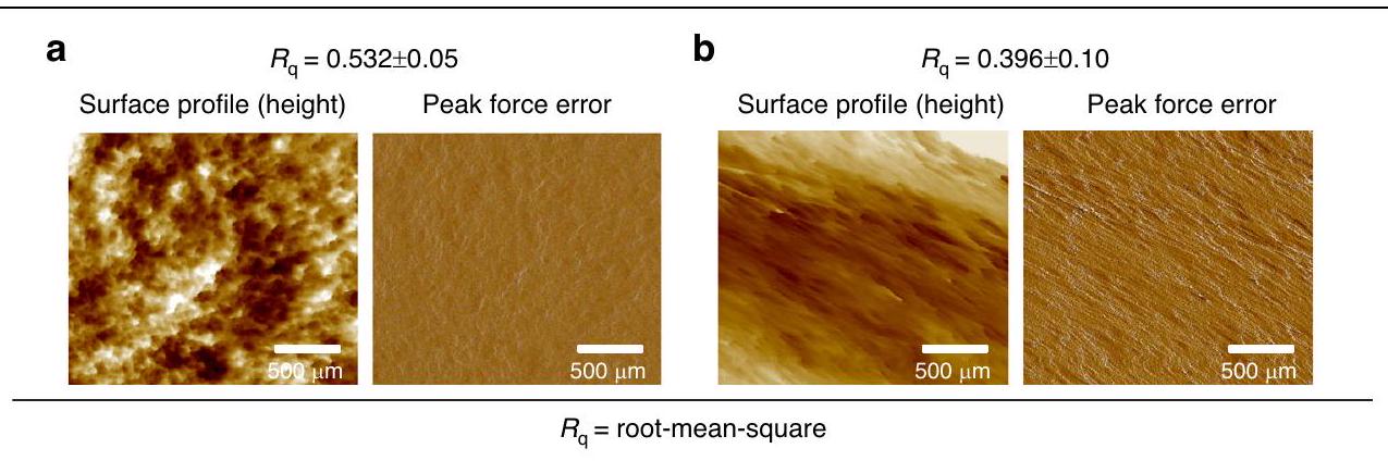
يمكن أن تؤثر التغيرات الدقيقة في الارتفاع عبر السطح على التفاعلات مع الجلد قد تعيق السطح الخشن الاختراق السلس، مما يتطلب مزيدًا من القوة لاختراق الجلد، مما قد يزيد من حساسية الألم وقد يتسبب في تلف كل من الإبر الدقيقة والجلد.
تم تقييم MNs لخصائص خشونة السطح باستخدام المجهر الذري (AFM). GelMA/ PVA ( أظهرت MNs خشونة قدرها بينما أظهرت MNs من PVA/PVP/HA (12/5/1، w/v) قيمة خشونة أقل من بدون أي طلاءات إضافية، كما هو موضح في الشكل 5a، b. نظرًا لأن GelMA/PVA (20/3، w/v) يتكون من مواد مختلفة وكان لديه انتفاخ أعلى (هيكل أكثر مسامية)، فمن المحتمل أن يكون هذا قد ساهم في زيادة في خشونة السطح مقارنةً بـ PVA/PVP/HA (12/5/1، w/v) MNs. كما كان من الملحوظ أن GelMA/PVA (20/
الشكل 5 صور AFM تظهر التضاريس السطحية لـ MNs. ملف السطح مع اختلافات ارتفاع مرئية وتصحيح خطأ القوة القصوى للتغيرات في تفاعلات الطرف-العينة. جلما/بي في إيه ب PVA/PVP/HA حجم مسح AFM:
يبدو أن PVA/PVP/HA (12/5/1، w/v) يتمتع بسطح أكثر نعومة مع تباين أقل في الارتفاع، بينما يظهر (3، w/v) بسطح أكثر مسامية وتضاريس متغيرة. يوفر تحليل خشونة السطح تفاصيل مفيدة حول هيكل MNs، حيث يشير السطح الأكثر نعومة إلى عملية تصنيع واستنساخ محسّنة بشكل جيد.

جهاز إدخال MNs واستخراج ISF بمساعدة الاهتزازات الدقيقة مع متحكم دقيق من نوع أردوينو

لقد طورت مجموعتنا سابقًا جهاز تطبيق MN قادر على توليد اهتزازات بترددات تتراوح من 50 إلى . لقد دمجت هذه الدراسة جهاز التطبيق مع منصة أردوينو لتعزيز دقته وتحكمه. ظلت معايير التصميم العامة مثل الارتفاع والعرض أو الجسم الرئيسي للجهاز كما هي ومتسقة مع التصميم السابق. ومع ذلك، تم إجراء تحسينات كبيرة على اتصالات الدائرة. في البداية، كان جهاز التطبيق مزودًا بمحرك اهتزاز واحد (ERM أو LRA). في النسخة المعدلة، تم توصيل محركين من نوع ERM بشكل متوازي على المكبس، يتم التحكم فيهما وتزامنهما باستخدام بيئة تطوير أردوينو المتكاملة (IDE)، كما هو موضح في الشكل 6a. أنشأ هذا الإعداد اهتزازات متناظرة عبر رأس المكبس، مما أدى إلى توزيع أكثر انتظامًا لنمط الاهتزاز. بالمقابل، قد يؤدي وضع محرك واحد فقط على الجانب إلى اهتزازات غير متساوية، مع تأثيرات أقوى بالقرب من المحرك وتأثيرات أضعف بعيدًا عنه. تم تفضيل محركات ERM لكفاءتها في استهلاك الطاقة وتكلفتها المنخفضة، حيث تنتج بشكل أساسي اهتزازات عرضية. تم برمجتها عبر بيئة تطوير أردوينو لإدارة عمليات المحركات والتحكم بدقة في تردد الاهتزاز (50 هرتز و100 هرتز). هذا ألغى الحاجة إلى الضبط اليدوي باستخدام مقبض مقاومة، والذي يمكن أن يكون غير دقيق وصعب الضبط بدقة على الترددات المطلوبة. أو 100 هرتز يمكن أن تؤدي هذه الدقة غير الدقيقة إلى نتائج غير متسقة، خاصة إذا لم يتم تحسين تردد الاهتزاز بشكل صحيح.
برمجة من خلال بيئة تطوير أوردوينو (Arduino IDE) مكنت من تحكم أدق من التعديلات اليدوية (المقاوم المتغير).
تعزيز الوظائف العامة للنظام. على الرغم من ذلك، تم دمج مقاوم متغير كطريقة تحكم احتياطية، مما يسمح بإجراء تعديلات يدوية على الجهد المطبق على محركات ERM عند الضرورة. هذا يضمن أن التحكم اليدوي لا يزال متاحًا إذا لم يكن IDE الخاص بـ Arduino متاحًا. لذلك، تم إدخال ترانزستورات لتكبير الإشارة إلى مستوى الجهد المطلوب. كما تمت إضافة ثنائيات لحماية الترانزستورات من ارتفاعات الجهد العكسي والحفاظ على استقرار الدائرة. علاوة على ذلك، تم استخدام مقاومات لتحديد التيار المتدفق عبر الترانزستورات والمحركات، مما يضمن تشغيلًا آمنًا وفعالًا. عندما يقرأ Arduino الإشارات من المقاوم المتغير، فإنه يحولها إلى جهد، والذي يتحكم بعد ذلك في اهتزاز محركي ERM، مترجمًا الإشارات الكهربائية إلى اهتزاز مادي. الشكل 6ب يوضح التصميم الميكانيكي والتكوين الداخلي لجهاز MN. يقوم زناد الإدخال ببدء العملية، بينما يوفر نابض الضغط القوة اللازمة لدفع MNs إلى الجلد.
تعتبر القدرة على اختراق الجلد بشكل متسق ودقيق واحدة من التحديات الأساسية للإبر القابلة للتورم، والتي تتأثر بعوامل مختلفة مثل القوة المطبقة، وسرعة الإدخال، والخصائص الميكانيكية لـ . بينما تعتبر طريقة الضغط بالإبهام (التطبيق اليدوي) بسيطة ومتاحة، إلا أنها قد تؤدي إلى أعماق اختراق غير متساوية ونتائج غير متسقة. علاوة على ذلك، فإن الإدخال اليدوي ينتج عنه قوة وسرعة غير متسقة، مما يؤدي إلى تأثيرات عالية أو منخفضة غير متوقعة مع دقة منخفضة. تكشف الملاحظات من الأنظمة البيولوجية، مثل البعوض والنحل، أن إدخال خرطومها يحدث بسرعة ملحوظة . علاوة على ذلك، يستخدم البعوض مزيجًا من الحركة الميكانيكية والاهتزازات الدقيقة لاختراق الجلد بكفاءة مع الحد الأدنى من الانزعاج . يبرز هذا الفعالية الطبيعية للسرعة والاهتزاز في اختراق أسطح الجلد بكفاءة. لذلك، تم تطوير جهاز التطبيق لمعالجة هذه التحديات من خلال تقديم فوائد كبيرة لإدخال الجلد مع الحد الأدنى من التدخل. مع قدرته على التحكم في التأثير المطبق، يمكن لجهاز التطبيق
الشكل 6 جهاز التطبيق MN وآلياته التشغيلية من التصميم والوظائف. أ رسم تخطيطي لنظام التحكم الإلكتروني لجهاز التطبيق، يوضح الاتصالات بين المتحكم الدقيق (Arduino Uno) المتصل بمحركين ERM باستخدام مقاوم متغير، وترانزستورات، ومقاومات، وثنائيات، ومفتاح، وبطارية. يمكّن المفتاح الاهتزاز عند ترددات 50 هرتز أو 100 هرتز عند تفعيله. ب توضيح للتكوين الداخلي لآلية المكبس مع محركين ERM لتوفير الاهتزاز، مع تسليط الضوء على زناد الإدخال، والاتصال بالمتحكم الدقيق، ونابض الضغط. ج مقارنة بين الميكانيكا الحيوية لطريقة إدخال MN بالضغط بالإبهام مقابل طريقة إدخال MN بمساعدة جهاز التطبيق، مع تسليط الضوء على الاختلافات في القوة المطبقة، وسرعة الإدخال، والدقة. د آلية التشغيل خطوة بخطوة لجهاز التطبيق من فتح المكبس إلى تفعيله على العينة. هـ صورة لتكوين جهاز التطبيق المجمع مع صورة مكبرة تظهر عرضًا قريبًا لجهاز التطبيق المصنوع حسب الطلب
توفير دقة أكبر في تطبيق MN وفعالية استخراج ISF. يبرز الشكل 6ج الميكانيكا الحيوية للجلد لتطبيق MN بمساعدة جهاز التطبيق مقارنة بالإدخال اليدوي.
آلية التشغيل خطوة بخطوة لجهاز التطبيق، الذي لديه سرعة واهتزازات تبلغ 50 و 100 هرتز، موضحة في الشكل 6د. تبدأ الآلية بفتح المكبس، وسحبه لأعلى، وضغط
النابض وتخزين الطاقة الكامنة. ثم يتم قفل المكبس للحفاظ على هذا الضغط. عند التفعيل، يتم تحرير الطاقة المخزنة في النابض، مما يدفع MNs إلى عينة الجلد بقوة ودقة محكومة. الشكل 6هـ يظهر الإعداد الفعلي لجهاز التطبيق المتصل بالمكون الإلكتروني لاختبار إدخال MN.

إدخال MNs، استخراج ISF، واستعادة الجلوكوز

تم إجراء اختبار أولي باستخدام بارافيلم للتحقيق في تأثير الاهتزاز الدقيق على اختراق الجلد. شمل ذلك الإدخال اليدوي وتطبيق تردد الاهتزاز عند 50 هرتز و 100 هرتز على نموذج جلد بسمك 1.1 مم يتكون من 8 طبقات من بارافيلم. تعتبر الطبقة الأولى من بارافيلم حاسمة لأنها تمثل التفاعل الأولي لـ MNs مع . يوفر الاختبار على الطبقة الأولى المعلومات الأكثر صلة حول كيفية أداء MNs على الجلد.
نسبة MNs الحلزونية في مجموعة التي اخترقت نموذج الجلد بدون اهتزاز للطبقة الأولى كانت و لجلما/بفا (20/3، ) وPVA/PVP/HA (12/5/1، w/v) على التوالي. عندما تم إدخال الاهتزاز ، أظهرت MNs جلما/بفا ، w/v) توزيعات ثقوب دقيقة في بارافيلم تبلغ ، مما زاد من كفاءة الاختراق على الطبقة الأولى بنسبة . بالمثل، بالنسبة لـ PVA/PVP/HA (12/5/1، MNs، كانت نسب الثقوب الدقيقة للطبقة الأولى ، وهو ما يمثل زيادة بنسبة مقارنة بالإدخال اليدوي. أظهرت النتائج أيضًا أن زيادة التردد من 50 هرتز إلى 100 هرتز زادت بشكل كبير من كفاءة الاختراق إلى و لجلما/بفا ( ) وPVA/PVP/HA ( )، على التوالي. على الرغم من أن كلا النوعين من MNs يمكن أن يخترق عدة طبقات من بارافيلم، إلا أن عدد الثقوب انخفض تدريجيًا داخل كل طبقة. كما لوحظ أن قطر الثقوب في بارافيلم في الطبقة الأولى أكبر من تلك الموجودة في الطبقتين الثانية والثالثة. بلغ عمق الاختراق الأقصى المحسوب لكلا النوعين من MNs داخل بارافيلم، الشكل 7أ. بالنظر إلى السمك المتوسط للـ SC هو ، أظهرت النتائج أن جهاز التطبيق مع الاهتزاز عزز كفاءة الاختراق وأنتج المزيد من الثقوب الدقيقة على نموذج الجلد، وهو تحسين حاسم مقارنة بالإدخال اليدوي وضروري للاستخراج الناجح لـ ISF. بسبب سرعة الاقتراب لجهاز التطبيق، يحدث الاختراق إلى العمق الكامل لـ دون اهتزازات عرضية متعددة لـ MNs. ومع ذلك، خلال فترة الاتصال الربيعي بعد الإدخال لبضع ثوانٍ بعد الإدخال، تحدث مئات الاهتزازات (قبل إيقاف الاهتزازات)، مما يوسع كل من مسام MN مع تحسين كبير في كفاءة الاختراق وامتصاص السوائل في النهاية.
على الرغم من أن اختبار بارافيلم يوفر رؤى قيمة لتحليل قدرات اختراق الجلد لـ MNs
قبل الاختبار على عينات بيولوجية (جلد أذن خنزير)، تم الإبلاغ عن أنه يظهر أعماق اختراق أعلى من تلك التي لوحظت في جلد الخنزير . لذلك، تم دراسة اختبار إدخال MNs بشكل أكبر على جلد أذن الخنزير لفهم الفرق بين استخدام التطبيق المعزز بالاهتزاز والإدخال اليدوي (باستخدام ضغط الإبهام). تم تطبيق مجموعات MN يدويًا ومع جهاز التطبيق المصنوع حسب الطلب و 100 هرتز بسرعة من مسافة محددة على جلد أذن الخنزير. بالنسبة لـ جلما/بفا ( )، كانت كفاءة الاختراق على جلد أذن الخنزير مع الإدخال اليدوي وجهاز التطبيق مع تعزيز الاهتزاز عند 50 هرتز و 100 هرتز هي و على التوالي. أشارت النتائج إلى انخفاض بنسبة (يدوي)، و في كفاءة الاختراق مقارنة بالاختبارات التي أجريت على بارافيلم. بالمثل، بالنسبة لـ PVA/PVP/HA ( ) MNs، أظهرت الترددات الأعلى معدلات اختراق محسنة مع للإدخال اليدوي، عند 50 هرتز)، و عند 100 هرتز. ومع ذلك، كان هناك أيضًا انخفاض في كفاءة الاختراق بنسبة للإدخال اليدوي، عند 50 هرتز، و عند 100 هرتز مقارنة بنتائج اختبار بارافيلم.
بعد تطبيق مجموعات MN يدويًا لمدة 5 دقائق على جلد أذن الخنزير، كان امتصاص ISF لـ جلما/بفا (20/3، w/v) فقط . ومع ذلك، باستخدام جهاز التطبيق، زاد امتصاص ISF لـ جلما/بفا إلى و عند 50 هرتز و 100 هرتز، على التوالي. بالنسبة لـ PVA/PVP/HA ( )، استخرجت مجموعات MN المضغوطة بالإبهام من ISF، بينما أدى استخدام جهاز التطبيق المعزز بالاهتزاز إلى تحسين الاستخراج إلى و عند 50 هرتز و 100 هرتز على التوالي، الشكل 7ب. كما هو متوقع، كانت كفاءة الاختراق عند ترددات الاهتزاز المختلفة (يدوي، 50 هرتز، 100 هرتز) أعلى في بارافيلم مقارنة بجلد أذن الخنزير، كما هو موضح في الشكل 7ج. العلاقة بين كفاءة الاختراق وحجم ISF المستخرج واضحة حيث أدت الكفاءة الأعلى للاختراق عند و 100 هرتز) إلى حجم أعلى من امتصاص ISF. أظهرت النتائج أنه عند تردد 100 هرتز، أظهرت MNs معدل اختراق أعلى بشكل ملحوظ، مما أدى إلى إنشاء عدد أكبر من الثقوب الدقيقة القابلة للحياة وفي نفس الوقت توسيع كل مسام دقيقة في جلد أذن الخنزير مقارنة ببارافيلم، الشكل 7د، هـ. يمكن أن يُعزى انخفاض الكفاءة مع الضغط اليدوي مقارنة بالتشغيل بمساعدة جهاز التطبيق إلى توزيع القوة غير المتساوي عبر مجموعة MN. أصابع الإنسان أقل دقة في الحفاظ على ضغط ثابت، مما يؤدي إلى تباين في كفاءة الاختراق وعمق . آلية توزيع القوة عبر هيكل الجلد أثناء إدخال MN، يدوي مقابل مساعد جهاز التطبيق، موضحة في الشكل التكميلي S4.
سرعة إدخال MN أيضًا عامل حاسم يؤثر على مقاومة الجلد أثناء الاختراق. الدراسات
الشكل 7 تقييم قدرات إدخال واستخراج MN الحلزوني. أ كفاءة الاختراق (%) عند أعماق بارافيلم المختلفة (127، 254، 381، و ) تحت ترددات مختلفة (يدوي و 100 هرتز). ب حجم امتصاص ISF (ملغ) من جلد أذن الخنزير عند ترددات مختلفة (يدوي، 50 هرتز، و 100 هرتز). ج مقارنة كفاءة الاختراق (%) لـ MNs عبر ترددات مختلفة (يدوي، 50 هرتز، و 100 هرتز) بين بارافيلم وجلد أذن الخنزير. د مجموعة MN المرفقة برأس مكبس التطبيق باستخدام شريط لاصق مزدوج الوجه للاختبارات الإدخال على بارافيلم تظهر تأثير ترددات 50 هرتز و 100 هرتز على التوحيد في الطبقتين الأولى والثانية من بارافيلم لـ GelMA/PVA ( ، w/v) MNs. e الثقوب الصغيرة التي أنشأتها MNs مرئية على جلد أذن الخنزير بترددات مختلفة (يدوي، 50 هرتز، و100 هرتز) f رسم بياني عمودي لمعدل استرداد الجلوكوز (%) لكلا نوعي MN. تركيزات الجلوكوز المكتشفة بواسطة MNs من GeIMA/PVA (20/3، w/v) في هيدروجيل الأجاروز (نقاط زرقاء) مقابل التركيز الفعلي للجلوكوز (نقاط حمراء). تركيزات الجلوكوز المكتشفة بواسطة PVA/PVP/HA MNs في هيدروجيل الأجاروز (نقاط زرقاء) مقابل التركيز الفعلي للجلوكوز (نقاط حمراء)
لقد أظهرت الدراسات أن زيادة سرعة الإدخال تقلل من القوة المطلوبة لاختراق الجلد. . هذا التأثير مهم بشكل خاص في المواد اللزجة المرنة مثل الجلد،
حيث تسبب السرعات الأعلى تشوهًا أكبر، مما يؤدي إلى خفض قوة كسر الجلد وزيادة اختراق الجلد . هذه نقطة مهمة لـ
MN القابلة للتورم، التي عادة ما تكون لديها قوة ميكانيكية أقل من الأنواع الأخرى بسبب قدرتها على التورم. علاوة على ذلك، فإن الطبيعة الديناميكية للاهتزاز تسمح لـ MNs بتجاوز المقاومة اللزجة الطبيعية للجلد بشكل أكثر فعالية من تطبيق القوة الثابتة. إن الجمع بين السرعة ( ) واهتزاز ( ) يمكّن MNs القابلة للتورم من التغلغل بعمق في الجلد مع الحد الأدنى من قوة الدفع. بينما قد يؤدي الضغط اليدوي نظريًا إلى تطبيق مزيد من القوة، إلا أنه يفتقر أيضًا إلى تأثير توسيع الميكروثقوب، مما يؤدي إلى كفاءة أقل في امتصاص السوائل. علاوة على ذلك، قد يتسبب الضغط المفرط في تلف MNs أو يسبب عدم الراحة. لذلك، حققت تردد اهتزاز يبلغ 100 هرتز نتائج مثالية للاختبار على جلد أذن الخنزير، مما يعزز كلاً من كفاءة التغلغل وتوسيع الميكروثقوب، مما يؤدي معًا إلى تحسين استخراج ISF.
ومع ذلك، بسبب الطبيعة المتورمة للميكروإبر الهيدروجيل، تضعف بنيتها عند اختراقها للطبقة السطحية، مما يجعلها أقل قدرة على تحمل الاهتزاز المستمر. كما أن قدرة الميكروإبر على تحمل اختراق الطبقة السطحية المعزز بالاهتزاز مرتبطة أيضًا بالقوة الميكانيكية للميكروإبر. الترددات الأعلى ( تتطلب قوة ميكانيكية أكبر من الإبر الدقيقة (MNs) أثناء الحركة العرضية بينما تكون مدخلة في السائل بين الخلايا (SC) لعدة ثوانٍ بعد الإدخال. لذلك، تم إيقاف الاهتزازات خلال عملية استخراج السائل بين الخلايا (ISF) لتجنب ذوبان الإبر الدقيقة. كما أن الحجم الذي يتم الحصول عليه من الإدخال اليدوي متغير وعرضة للاختلافات بسبب القوة المطبقة عشوائيًا، والعمق، وزاوية الاختراق. يمكن أن تؤدي هذه الافتقار إلى الدقة إلى أعماق اختراق غير متساوية ودرجات متفاوتة من تضرر الجلد، مما يؤدي إلى نتائج غير موثوقة وجمع غير مثالي للسائل بين الخلايا. يضمن جهاز التطبيق قوة وسرعة إدخال متسقة. ) يُستخدم ويقلل من التباين بين التطبيقات المتكررة. هذه الوحدة مهمة لتحقيق نتائج موثوقة وقابلة للتكرار في استخراج ISF.
لتقييم قدرة الإبر الدقيقة على استعادة المؤشرات الحيوية، تم اختيار الجلوكوز كالجزيء الحيوي المستهدف داخل مصفوفة الجل الأجاروز. تم تطبيق مصفوفات الإبر الدقيقة على مصفوفة الأجاروز لمدة 5 دقائق، بعد ذلك تم إزالتها وذوبانها في لاستعادة الجلوكوز. أشارت النتائج إلى أن حجم السائل بين الخلايا المستخرج يمكن أن يؤثر على معدل استعادة الجلوكوز، كما هو موضح في الشكل 7f. على سبيل المثال، معدل استعادة GelMA/PVA ( ) و MNs من PVA/PVP/HA (12/5/1، وزن/حجم) كانت و أظهرت النتائج، على التوالي، أن زيادة حجم امتصاص السائل بين الخلايا (ISF) من GelMA/PVA (20/3، وزن/حجم) أدت إلى معدل استرداد جلوكوز أعلى مقارنةً بـ PVA/PVP/HA (12/5/1، وزن/حجم) MNs. يمكن أن تحتوي كميات صغيرة من ISF على عدد أقل بكثير من جزيئات الجلوكوز، مما يؤدي إلى زيادة التباين واحتمالية أكبر لحدوث أخطاء في القياس. يمكن أن يجعل ذلك من الصعب تحقيق قراءات دقيقة للجلوكوز، حيث أن العدد المنخفض من جزيئات الجلوكوز
قد تنخفض دون عتبة الحساسية لمجموعة اختبار الكشف عن الجلوكوز. تدعم دقة نتائجنا حقيقة أن مجموعة اختبار الكشف عن الجلوكوز المستخدمة حساسة للغاية، مما يسمح بالكشف بسهولة عن تركيزات الجلوكوز المستحثة من إلى . بالإضافة إلى ذلك، تجاوزت أحجام ISF المستخرجة لكل أنواع MN، مما ضمّن تركيزًا أعلى من الجلوكوز داخل السائل بين الخلايا للكشف. وقد أظهرت دراسة أيضًا أن كميات أكبر من السائل بين الخلايا توفر كشفًا أكثر استقرارًا ودقة للجلوكوز، حيث تقلل من تأثير التغيرات المحلية والتلوث المحتمل. أظهرت الارتباطات أن تركيزات الجلوكوز المكتشفة (النقاط الزرقاء) تتماشى بشكل وثيق مع التركيزات الفعلية (النقاط الحمراء) عبر النطاق الكامل، مع دلالة نقاط البيانات على مستوى عالٍ من الدقة. لـ GelMA/PVA لـ PVA/PVP/HA (12/5/1، وزناً/حجماً).

الخاتمة

بالنظر إلى النتائج المقدمة، يتناول بحثنا بعض القضايا الرئيسية والفجوات البحثية التي تم تحديدها في الأدبيات السابقة المتعلقة بالاستخراج الناجح للسائل بين الأنسجة باستخدام الألياف النانوية. وقد تم تسليط الضوء على أن اثنين من التحديات الحاسمة هما حجم العينة ووقت الاستخراج. بينما لا توجد حاليًا معايير محددة لحجم السائل بين الخلايا ووقت الاستخراج، من الضروري التعرف على المخاطر المحتملة المرتبطة بحجم السائل بين الخلايا المنخفض، حيث قد يؤدي ذلك إلى الحصول على مؤشرات حيوية غير كافية أو عدم الحصول عليها على الإطلاق. بالإضافة إلى ذلك، فإن الحفاظ على وقت استخراج قصير نسبيًا أمر ضروري للحفاظ على سلامة إبر الهيدروجيل وضمان نجاح استخراج السائل بين الخلايا. تناولت هذه الدراسة هذه التحديات الحرجة من خلال تقديم تصميم مبتكر، وطرق جديدة، وتحسين المواد، وتطوير عملية استخراج فعالة للسائل بين الخلايا باستخدام جهاز تطبيق مصمم خصيصًا. تؤكد هذه الروابط على أهمية النتائج في المساهمة في تقدم تكنولوجيا الإبر الدقيقة لتحسين التشخيصات والاستجابة العلاجية بدقة وفعالية.
تتأثر أداء الإبر الدقيقة (MNs) في استخراج السائل بين الأنسجة (ISF) بعدة عوامل، بما في ذلك تصميمها، وموادها، وقدرتها على الانتفاخ، وخصائصها الميكانيكية، وتقنية الإدخال. لذلك، كان أحد أهداف هذه الدراسة هو التحقيق في استخدام مادة GelMA فقط كمواد للإبر الدقيقة وتقييم قدرتها على استخراج حجم أكبر من السائل بين الأنسجة في فترة زمنية قصيرة. تشير الأبحاث السابقة إلى أنه بينما يمكن لـ GelMA و MNs المعتمدة على GelMA استخراج السائل بين الخلايا، فإن الأحجام عادة ما تبقى أقل من ، وغالبًا ما تتجاوز أوقات الاستخراج 10 دقائق. لذلك، قدمنا PVA كبوليمر هيدروفيل إضافي داخل مصفوفة GelMA لتحسين حجم الاستخراج من ISF. كان الهدف من إدخال PVA هو استكشاف وتعزيز خصائص الانتفاخ لـ MNs. تم إجراء تحليل شامل من خلال تغيير PVA
عائد قدره 5.8 جرام من 10 جرام الأولية. تم تخزين البوليمر المسبق في قبل الاستخدام.

درجة الاستبدال لجيلما

تم قياس مجموعات الميثاكريلاميد في GelMA عند بدقة عالية جهاز مطياف الرنين المغناطيسي النووي (Bruker Avance III 500 MHz، بريمن، ألمانيا). تم تحضير عينات GelMA والجيلاتين عن طريق إذابة 40 ملغ من GelMA أو الجيلاتين في تم حساب درجة الاستبدال (DS) للميثاكريلاميد على الجيلاتين (الشكل التكميلي S5) باستخدام تكامل بروتونات ميثيلين الليسين من GelMA والجيلاتين باستخدام المعادلة التالية:

تصنيع MNs من GeIMA و GeIMA/PVA

تم تحضير ثلاثة حلول مختلفة في PBS لتكرار مصفوفات MN: GelMA (20%، وزن/حجم)، GelMA/PVA (20/3، وزن/حجم) و GelMA/PVA (20/5، وزن/حجم). تم إضافة البريبوليمر المسامي GelMA في البداية إلى PBS عند حتى يذوب تمامًا. ثم تم خلط محلول GelMA المائي مع المحفز الضوئي Irgacure ) في لتحضير محلول GelMA. بشكل منفصل، تم إذابة PVA (وزن جزيئي 30 كيلودالتون) في PBS بتركيزين (3 و ، و/ف) تحت التحريك المستمر في بين عشية وضحاها. بعد ذلك، جلما ( ) تم إضافته إلى كل محلول PVA متجانس عند وتم التحريك لمدة 4 ساعات. إيرغاكور ( ) ثم أضيف، وتم وضع الخليط في حمام بالموجات فوق الصوتية عند لمدة 15 دقيقة. تم صب المحاليل المحضرة في قوالب الإبر الدقيقة وتم الطرد المركزي بسرعة 4000 دورة في الدقيقة لمدة 10 دقائق لملء تجاويف قوالب الإبر الدقيقة. ثم تم تعريض قوالب الإبر الدقيقة لأشعة UV. لمدة 250 ثانية. تم تجفيف القوالب المتشابكة في الظلام عند قبل أن يتم تقشيره للاستخدام لاحقًا.

تصنيع MNs من PVA/PVP/HA

PVA (Mw تم حل ( لمدة ساعتين في PBS تحت التحريك المستمر. PVP (وزن جزيئي 40 كيلودالتون، تم أيضًا إذابته باستخدام نفس الطريقة، بينما تم تحضير تركيزات مختلفة من HA (Mw 300 kDa) بشكل منفصل في ، و “، و/ح. PVP (وزن جزيئي 40 كيلودالتون، ) تم إذابته في ماء ميلي-كيو لمدة ساعة لإنشاء الحل الأساسي. ثم تم إعداد حلول PVA/PVP/HA من خلال دمج حلول PVA وPVP وHA المعدة مسبقًا بدقة. تلا ذلك إضافة كمية صغيرة من مادة الربط الجلوتارالدهيد إلى خليط التفاعل في لمدة ساعة واحدة. تم سحب محلول PVA/PVP/HA في قوالب MN وتم الطرد المركزي بسرعة 4000 دورة في الدقيقة لمدة 10 دقائق لضمان التغلغل الكامل في تجاويف القوالب. لتشكيل قاعدة MN قوية، تم ملء القوالب بشكل خفيف مرتين بشكل دوري بمحلول القاعدة PVP. ). القوالب المملوءة
تم تجفيفها عند أو 36 ساعة قبل أن يتم تقشيرها للاستخدام لاحقًا.

جهاز تطبيق مخصص يعتمد على أردوينو

تم طباعة جهاز التطبيق المخصص باستخدام طابعة ثلاثية الأبعاد (Teirtime) شركة Teirtime، الولايات المتحدة الأمريكية) مع خيوط من حمض البولي لاكتيك بنفس الهندسة الموصوفة في عمل مجموعتنا السابق . النسخة المحدثة من جهاز التطبيق مزودة بوحدة التحكم الدقيقة Arduino Uno للتحكم في النظام، الذي يتضمن محركات اهتزاز ERM، ومقوم ثنائي، وبطارية ليثيوم بوليمر، ومقاوم متغير، وترانزستور، ومقاوم. تم ضبط نطاق التردد مباشرة بين 50 و 100 هرتز باستخدام بيئة تطوير Arduino.
تم ضبط المقبض الذي يتحكم في سرعة مكبس الأخدود على بطاقة تأثير تبلغ 215.46 مللي جول. تم تفعيل رأس المكبس (مع مصفوفات MN المرفقة) بواسطة آلية زر ضغط لضرب العينة (بارافيلم وجلد أذن الخنزير) بينما تم إدخال الاهتزاز (50 هرتز أو 100 هرتز) باستخدام بيئة تطوير Arduino. تم التحقق من سرعة تأثير النموذج الأولي باستخدام تقنيتين: تحليل الكاميرا عالية السرعة والنمذجة النظرية، كما تم تحديده في دراستنا السابقة. .

نسب انتفاخ MNs في PBS و ISF الاصطناعي

تم تقييم نسب التورم للميكروإبر من خلال قياس التغيرات في الكتلة قبل وبعد غمرها في كل من محلول PBS ومحلول السائل بين الخلوي الاصطناعي. تم غمر عينات مصفوفة الميكروإبر في PBS والسائل بين الخلوي الاصطناعي في لتحديد الفرق بين الوزن الرطب ( ) و الوزن الجاف ( ) في نقاط زمنية مختلفة ( ). كان الهدف هو مراقبة المراحل المبكرة ( ) لنسب التورم وتحليل الاتجاه على مر الزمن من خلال مراقبة التغيرات في الكتلة على فترات زمنية قصيرة نسبيًا (1 دقيقة). تم حساب نسبة التورم للـ MNs باستخدام المعادلة التالية:

تحديد الخصائص الميكانيكية

تم تقييم الخصائص الميكانيكية للـ MNs من خلال اختبارات الضغط باستخدام جهاز اختبار المواد ذو القوة المنخفضة (Instron 3343، إنستران، ماساتشوستس، الولايات المتحدة الأمريكية). لكل اختبار، تم استخدام مجموعة من MN. ) تم وضعه مع جانب الإبرة لأعلى على اللوحة الثابتة لجهاز اختبار الشد باستخدام شريط لاصق مزدوج الوجه وضغطه بمعدل حتى ارتفاع هابط أقصى قدره 0.5 مم مع خلية تحميل ثابتة بوزن 50 نيوتن. كانت وضعية الفشل الرئيسية المسجلة هي الانبعاج دون تأثيرات التواء ملحوظة أو التواء إضافي عند الفشل. تم تسجيل القوة مقابل الإزاحة لحساب معامل الانضغاط. من الضغط والضغط انحناء مع
المعادلات التالية:
أين هو القوة الضاغطة المطبقة (نيوتن)، هو المساحة المقطعية لمصفوفة MN حيث يتم تطبيق القوة الضاغطة ( ) ، هو معدل مجموعة خلية الحمل لجهاز اختبار المواد (UTM)، هو وقت التشوه المرن و هو وقت تقريبي عندما تصل خلية الحمل لأول مرة إلى MNs.

توصيف الشكل

تم التقاط صور لمصفوفات MN الحلزونية (الرئيسية والنسخ) باستخدام ميكروسكوب رقمي (DSX1000، أوليمبوس، اليابان) بتكبيرات مختلفة. ). تم إجراء التصوير بزاويا ميل قابلة للتعديل تتراوح من إلى .
تم تقييم الشكل الحلزوني للإبر الدقيقة باستخدام مجهر إلكتروني مس扫描 (SEM، JSM-7001F، JEOL، اليابان). تم طلاء الإبر الدقيقة بطبقة رقيقة بسماكة 12 نانومتر من البلاتين لمنع الشحن. ثم تم تصوير العينة في مجهر SEM ذو الانبعاث الميداني عند جهد تسريع قدره 10 كيلو فولت في وضع الفراغ العالي (HighVac) مع مستوى تكبير من تم إزالة قوالب مصفوفات MN بعناية قبل التصوير مباشرةً لتجنب أي ضرر محتمل.

خصائص السطح

تم استخدام المجهر الذري القوي (AFM، نظام Multimode 8-HR Nanoscope، Bruker، كاليفورنيا، الولايات المتحدة الأمريكية) في وضع ScanAsyst لرسم خريطة التضاريس السطحية للإبر الدقيقة (MNs). كانت هناك قواطع سيليكون (ScanAsyst Air، مجسات AFM من Bruker، كاليفورنيا، الولايات المتحدة الأمريكية) تتميز بثوابت زنبركية ضمن النطاق من وترددات الرنين بين تم استخدامه للقياسات. بالنسبة لتحضير العينة، تم وضع محاليل GelMA/PVA (20/3، وزناً/حجماً) و PVA/PVP/HA (12/5/1، وزناً/حجماً) بشكل فردي في كتل دائرية مسبقة الصنع (قطر 10 مم) وتم تجفيفها لاحقاً لمدة 36 ساعة في قبل الاختبار. تم تكوين معلمات المسح بحجم مسح 500 نانومتر عند 2 هرتز. تم إجراء تحليل الصور بعد ذلك بشكل غير متصل باستخدام برنامج تحليل NanoScope (بروكير، كاليفورنيا، الولايات المتحدة الأمريكية).

اختبار الإدخال واستخراج ISF خارج الجسم

تم تكديس ورقة بارافيلم المتاحة تجارياً في ثماني طبقات لكل طبقة، مجتمعة لتمثيل جلد الإنسان لاختبار الإدخال الأولي. MN
تم تطبيق المصفوفات على إعداد الجلد المحاكى يدويًا وباستخدام جهاز التطبيق المصنوع خصيصًا بترددات 50 هرتز و100 هرتز. بعد الإدخال، تم إيقاف عملية الاهتزاز المجهري بعد بضع ثوانٍ حدثت خلالها توسيع الميكروثقوب، وبعد ذلك تم ترك مصفوفات الإبر الدقيقة في مكانها لمدة 30 ثانية قبل إزالتها. ثم تم فحص الثقوب في طبقات البارافيلم تحت المجهر (كارل زيس أكسيو، يينا، ألمانيا) لتقييم كفاءة الإدخال.
تم الحصول على جلد أذن الخنزير المذبوح حديثًا من جزار محلي (بريسبان، أستراليا) وتم تخزينه في ورق الألمنيوم في حتى الاستخدام. قبل إدخال مصفوفة MN، تم تنظيف الجلد بالماء النقي للغاية وتم إذابته في PBS لمدة ساعتين عند تم قياس سمك العينة عند . في البداية، تم تطبيق مصفوفة MN مباشرة على جلد أذن الخنزير دون استخدام جهاز التطبيق المصنوع خصيصًا. بعد ذلك، تم إدخال مصفوفات MN باستخدام جهاز التطبيق بسرعة “، مع تطبيق الاهتزاز فقط خلال عملية الإدخال وبعد بضع ثوانٍ بترددات 50 هرتز و100 هرتز. ومع ذلك، لم يتم تطبيق أي اهتزاز خلال مرحلة استخراج السائل بين الأنسجة. تم ترك المصفوفة في مكانها لمدة 5 دقائق قبل إزالتها. تم تحديد حجم السائل بين الأنسجة الناتج عن طريق طرح الوزن الأولي للمصفوفة ( ) من الوزن المقاس بعد الاستخراج ( تريبان الأزرق ) تم استخدامه لتحديد وصبغ الجلد وتم حضنه لمدة 5 دقائق لالتقاط الصور البصرية.

كشف تركيز الجلوكوز في المختبر

تم تحضير هيدروجيل الأجاروز بتركيز 3% (وزن/حجم) مع تركيزات مختلفة من الجلوكوز: 100، 200، 300، 400، و د.ل. لاكتشاف تركيز الجلوكوز بواسطة مصفوفات MN، الوزن الجاف للمصفوفة ( ) و الوزن الرطب ( تم قياسها بعد إدخالها في هلام الأجاروز الذي يحتوي على تركيزات مختلفة من الجلوكوز لمدة 10 دقائق في كل اختبار. بعد الإدخال، تم إزالة الإبر الدقيقة بعناية من المصفوفة ووضعها في أنابيب الطرد المركزي التي تحتوي على 1 مل من PBS (درجة الحموضة 7.4). تم تسخين الأنابيب عند لمدة 15 دقيقة لتحرير الجلوكوز. تم قياس الامتصاص عند 540 نانومتر بواسطة مطياف الأشعة فوق البنفسجية والمرئية (شيمادزو، UVmini1240، اليابان) وتم تحديده باستخدام مجموعة اختبار جلوكوز تجارية. تم الكشف عن تركيز الجلوكوز ( تم تحديد ( ) بواسطة مصفوفات MN باستخدام الصيغة التالية:
أين تركيز الجلوكوز من المنحنى القياسي باستخدام مجموعة الفحص، حجم PBS المضاف إلى أنبوب الطرد المركزي الكتلة الرطبة لمصفوفة MN، الكتلة الجافة لمصفوفة MN، كثافة الجلوكوز المستخرج بواسطة MNs .

التحليل الإحصائي

تم إجراء التحليل الإحصائي للبيانات باستخدام تحليل التباين الأحادي، مع الإشارة إلى مستويات الدلالة بواسطة النجوم: * لـ ، ** لـ ، و *** لـ تم استخدام Origin Pro 2022 و Python لجميع الحسابات الإحصائية. تُعرض البيانات كمتوسط ± الانحراف المعياري من خمسة تجارب مستقلة. .

شكر وتقدير

استخدم هذا العمل عقدة كوينزلاند من مرفق التصنيع الوطني الأسترالي المدعوم من NCRIS (ANFF). لم يكن من الممكن القيام بالعمل المنجز دون الدعم السخي من شركة AXT Pty Ltd. يتم توجيه الشكر الخاص إلى جاريت لي وبرادمان ماركس من AXT لمساعدتهما في التصنيع الدقيق باستخدام نظام الطباعة المجسمة المتقدم (PuSL) من بوسطن مايكرو فابريكيشن. شكر خاص لفاهد إبرهيم نجاد على إعداد محاليل PVA/PVP الأولية. لم تتلقَ هذه البحث أي منح محددة من وكالات التمويل العامة أو التجارية أو غير الربحية.

تفاصيل المؤلف

كلية الهندسة، جامعة كوينزلاند الجنوبية، سبرينغفيلد، كوينزلاند 4300، أستراليا. مركز المواد المستقبلية، معهد الهندسة المتقدمة وعلوم الفضاء، جامعة كوينزلاند الجنوبية، سبرينغفيلد، كوينزلاند، أستراليا. كلية الهندسة، جامعة برمنغهام، برمنغهام B15 2TT، المملكة المتحدة. أوكساكوس المحدودة، دورشيستر على ضفاف التايمز OX10 7HN، المملكة المتحدة. كلية الهندسة، جامعة نيو ساوث ويلز، أستراليا، سيدني، نيو ساوث ويلز 2052، أستراليا. كلية الهندسة والعلوم الفيزيائية، مدرسة الهندسة، جامعة برمنغهام، برمنغهام B15 2TT، المملكة المتحدة

مساهمات المؤلفين

K.M.S. وز.ف.رتم تصور فكرة الورقة. قام ك.م.س. بإجراء التجارب وتحليل البيانات. قام ك.م.س. و أ.م. بتنفيذ تخليق GelMA. كتب ك.م.س. الورقة، وساعده ب.أ. قام ب.د.ب. و ج.ج.د. بتوجيه ومراجعة العمل.ز.ف.رقاموا بتوجيه ومراجعة وإشراف الدراسة. ساهم جميع المؤلفين في المناقشة العامة ووافقوا على النسخة النهائية.

تضارب المصالح

يعلن المؤلفون عدم وجود مصالح متنافسة.
تمت جميع التجارب التي تتضمن منتجات حيوانية بموافقة لجنة أخلاقيات الحيوانات في جامعة كوينزلاند الجنوبية، أستراليا (رقم الموافقة الأخلاقية: 23BIOS008).
معلومات إضافية النسخة الإلكترونية تحتوي على مواد إضافية متاحة فيhttps://doi.org/10.1038/s41378-024-00850-x.
تاريخ الاستلام: 10 يوليو 2024 تاريخ المراجعة: 26 أكتوبر 2024 تاريخ القبول: 21 نوفمبر 2024
نُشر على الإنترنت: 08 يناير 2025

References

  1. Lee, B. H., Shirahama, H., Cho, N. J. & Tan, L. P. Efficient and controllable synthesis of highly substituted gelatin methacrylamide for mechanically stiff hydrogels. RSC Adv. 5, 106094-106097 (2015).
  2. Heikenfeld, J. et al. Accessing analytes in biofluids for peripheral biochemical monitoring. Nat. Biotechnol. 37, 407-419 (2019).
  3. Sriram, S. Study of needle stick injuries among healthcare providers: evidence from a teaching hospital in India. J. Fam. Med. Prim. Care 8, 599-603 (2019).
  4. Serafin, A., Malinowski, M. & Prażmowska-Wilanowska, A. Blood volume and pain perception during finger prick capillary blood sampling: are all safety lancets equal? Postgrad. Med. 132, 288-295 (2020).
  5. Biswas, J. et al. Effect of Hypodermic Needle Versus Safety Lancet on the Fear and Anxiety of Needle Prick Among Undergraduate Medical Students During
Hematology Practical: A Cohort Study From a Resource-Limited Setting. Cureus 14, e27458 (2022).
6. McMurtry, C. M. et al. Far from “Just a Poke”: common painful needle procedures and the development of needle fear. Clin. J. Pain. 31, S3-S11 (2015).
7. Raju, K. S. R., Taneja, I., Singh, S. P. & Wahajuddin Utility of noninvasive biomatrices in pharmacokinetic studies. Biomed. Chromatogr. 27, 1354-1366 (2013).
8. Brinkman, J. E., Dorius, B. & Sharma, S. Physiology, Body Fluids. [Updated 2023 Jan 27]. In: StatPearls [Internet]. Treasure Island (FL): StatPearls Publishing; 2024 Jan-. Available from: https://www.ncbi.nlm.nih.gov/books/NBK482447/.
9. Elhassan E. A. & Schrier R. W. Comprehensive Clinical Nephrology: Fourth Edition, 85-99 (2010).
10. Wiig, H. & Swartz, M. A. Interstitial fluid and lymph formation and transport: physiological regulation and roles in inflammation and cancer. Physiol. Rev. 92, 1005-1060 (2012).
11. Mathew, J., Sankar, P. & Varacallo, M. Physiology, Blood Plasma. 2023 Apr 24. In: StatPearls [Internet]. Treasure Island (FL): StatPearls Publishing; 2024 Jan-.
12. Sagedal, S. et al. Intermittent saline flushes during haemodialysis do not alleviate coagulation and clot formation in stable patients receiving reduced doses of dalteparin. Nephrol. Dial. Transpl. 21, 444-449 (2006).
13. Müller, A. C. et al. A comparative proteomic study of human skin suction blister fluid from healthy individuals using immunodepletion and ITRAQ labeling. J. Proteome Res. 11, 3715-3727 (2012).
14. Reusch, M. K., Mansbridge, J. N., Nickoloff, B. J. & Morhenn, V. B. Immunophenotyping of skin cells during healing of suction blister injury. Dermatology 183, 179-183 (1991).
15. Bruschi, M. L. Strategies to modify the drug release from pharmaceutical systems. 1-199 (Woodhead Publishing, Elsevier, 2015). https://doi.org/10.1016/ C2014-0-02342-8.
16. Saifullah, K. M. & Faraji Rad, Z. Sampling dermal interstitial fluid using microneedles: A review of recent developments in sampling methods and microneedle-based biosensors. Adv. Mater. Interfaces 10, 2201763 (2023).
17. Ma, S., Li, J., Pei, L., Feng, N. & Zhang, Y. Microneedle-based interstitial fluid extraction for drug analysis: advances, challenges, and prospects. J. Pharm. Anal. 13, 111-126 (2023).
18. Gill, H. S., Denson, D. D., Burris, B. A. & Prausnitz, M. R. Effect of microneedle design on pain in human volunteers. Clin. J. Pain. 24, 585-594 (2008).
19. Rad, Z. F., Prewett, P. D. & Davies, G. J. An overview of microneedle applications, materials, and fabrication methods. Beilstein J. Nanotechnol. 12, 1034-1046 (2021).
20. Zhang, X., Zhang, W., Wu, W. & Chen, J. Programmable SARS-CoV-2 mutation detection platform based on ligation-triggered isothermal exponential amplification coupled with self-priming amplification. Microchem. J. 195, 109477 (2023).
21. Yoon, H. J. et al. Cold water fish gelatin methacryloyl hydrogel for tissue engineering application. PLoS ONE 11, e0163902 (2016).
22. Doğan, E. E. et al. Synthesis, characterization and some biological properties of PVA/PVP/PN hydrogel nanocomposites: antibacterial and biocompatibility. Adv. Mater. Sci. 19, 32-45 (2019).
23. Shi, Y., Xiong, D., Liu, Y., Wang, N. & Zhao, X. Swelling, mechanical and friction properties of PVA/PVP hydrogels after swelling in osmotic pressure solution. Mater. Sci. Eng.: C. 65, 172-180 (2016).
24. Sun, M. et al. Synthesis and properties of gelatin methacryloyl (GelMA) hydrogels and their recent applications in load-bearing tissue. Polymers 10, 1290 (2018).
25. Teodorescu, M., Bercea, M. & Morariu, S. Biomaterials of PVA and PVP in medical and pharmaceutical applications: perspectives and challenges. Biotechnol. Adv. 37, 109-131 (2019).
26. Zhu, J. et al. Phase segregated Pt-SnO2/C nanohybrids for highly efficient oxygen reduction electrocatalysis. Small 16, 1905910 (2020).
27. . et al. Swellable PVA/PVP hydrogel microneedle patches for the extraction of interstitial skin fluid toward minimally invasive monitoring of blood glucose level. Analyst 147, 1478-1491 (2022).
28. Fonseca, D. F. S. et al. Swellable gelatin methacryloyl microneedles for extraction of interstitial skin fluid toward minimally invasive monitoring of urea. Macromol. Biosci. 20, 2000195 (2020).
29. Chang, H. et al. A swellable microneedle patch to rapidly extract skin interstitial fluid for timely metabolic analysis. Adv. Mater 29, 1702243 (2017).
30. Ebrahiminejad, V., Rad, Z. F., Prewett, P. D. & Davies, G. J. Fabrication and testing of polymer microneedles for transdermal drug delivery. Beilstein J. Nanotechnol. 13, 629-640 (2022). 13:55.
31. Römgens, A. M., Bader, D. L., Bouwstra, J. A., Baaijens, F. P. T. & Oomens, C. W. J. Monitoring the penetration process of single microneedles with varying tip diameters. J. Mech. Behav. Biomed. Mater. 40, 397-405 (2014).
32. Han, W. T. et al. Improved cell viability for large-scale biofabrication with photo-crosslinkable hydrogel systems through a dual-photoinitiator approach. Biomater. Sci. 8, 450-461 (2019).
33. He, R. et al. Carbon nanotubes: construction of aptamer-siRNA chimera/PEI/5FU/Carbon nanotube/collagen membranes for the treatment of peritoneal dissemination of drug-resistant gastric cancer. Adv. Healthc. Mater. 9, 1901201 (2020).
34. Luo, Z. et al. Organ-on-a-Chip: organ-on-a-chip for cancer and immune organs modeling. Adv. Healthc. Mater. 8, 1801054 (2019).
35. Himawan, A. et al. Multifunctional low temperature-cured PVA/PVP/citric acidbased hydrogel forming microarray patches: Physicochemical characteristics and hydrophilic drug interaction. Eur. Polym. J. 186, 111836 (2023).
36. Makvandi, P. et al. Engineering microneedle patches for improved penetration: analysis, skin models and factors affecting needle insertion. Nano-Micro Lett. 13, 1 (2021).
37. Davis, S. P., Landis, B. J., Adams, Z. H., Allen, M. G. & Prausnitz, M. R. Insertion of microneedles into skin: measurement and prediction of insertion force and needle fracture force. J. Biomech. 37, 1155-1163 (2004).
38. Malek-Khatabi, A., Faraji Rad, Z., Rad-Malekshahi, M. & Akbarijavar, H. Development of dissolvable microneedle patches by CNC machining and micromolding for drug delivery. Mater. Lett. 330, 133328 (2023).
39. Nair, K. et al. Investigation of plasma treatment on micro-injection moulded microneedle for drug delivery. Pharmaceutics 7, 471-485 (2015).
40. Ebrahiminejad, V., Malek-khatabi, A. & Faraji Rad, Z. Influence of low-frequency vibration and skin strain on insertion mechanics and drug diffusion of PVA/ PVP dissolving microneedles. Adv. Mater. Technol. 9, 2301272 (2024).
41. Ling, J. et al. Critical roles of CX3CR1(+) mononuclear phagocytes in maintaining gut-liver axis health. J. Bionic Eng. 13, 303-304 (2016).
42. Aoyagi, S., Izumi, H. & Fukuda, M. Biodegradable polymer needle with various tip angles and consideration on insertion mechanism of mosquito’s proboscis. Sens. Actuators A Phys. 143, 20-28 (2008).
43. Kundan, K. K., Laha, S. & Ghatak, A. Vibration assisted puncturing of a soft brittle solid. Extrem. Mech. Lett. 26, 26-34 (2019).
44. Larrañeta, E. et al. A proposed model membrane and test method for microneedle insertion studies. Int. J. Pharm. 472, 65-73 (2014).
45. Czekalla, C., Schönborn, K. H., Lademann, J. & Meinke, M. C. Noninvasive determination of epidermal and stratum corneum thickness in vivo using two-photon microscopy and optical coherence tomography: impact of body area, age, and gender. Ski. Pharm. Physiol. 32, 142-150 (2019).
46. Alrimawi, B. H., Lee, J. Y., Ng, K. W. & Goh, C. F. In vitroevaluation of microneedle strength: a comparison of test configurations and experimental insights. RSC Pharm. 1, 227-233 (2024).
47. Leone, M. et al. Universal Applicator for Digitally-Controlled Pressing Force and Impact Velocity Insertion of Microneedles into Skin. Pharmaceutics 10, 211 (2018).
48. Kim, J. et al. Bioinspired microneedle insertion for deep and precise skin penetration with low force: why the application of mechanophysical stimuli should be considered. J. Mech. Behav. Biomed. Mater. 78, 480-490 (2018).
49. Mahvash, M. & Dupont, P. E. Mechanics of dynamic needle insertion into a biological material. IEEE Trans. Biomed. Eng. 57, 934-943 (2010).
50. Mahvash, M. & Dupont, P. E. Fast needle insertion to minimize tissue deformation and damage. IEEE Int. Conf. Robot. Autom. 2009, 3097-3102 (2009).
51. Steil, G. M. et al. Interstitial fluid glucose dynamics during insulin-induced hypoglycaemia. Diabetologia 48, 1833-1840 (2005).

  1. Correspondence: Zahra Faraji Rad (Zahra.FarajiRad@usq.edu.au)
    School of Engineering, University of Southern Queensland, Springfield, QLD 4300, Australia
    Centre for Future Materials, Institute for Advanced Engineering and Space Sciences, University of Southern Queensland, Springfield, QLD, Australia Full list of author information is available at the end of the article

Journal: Microsystems & Nanoengineering, Volume: 11, Issue: 1
DOI: https://doi.org/10.1038/s41378-024-00850-x
PMID: https://pubmed.ncbi.nlm.nih.gov/39774609
Publication Date: 2025-01-08

Micro-vibration assisted dual-layer spiral microneedles to rapidly extract dermal interstitial fluid for minimally invasive detection of glucose

Khaled Mohammed Saifullah , Asim Mushtaq , Pouria Azarikhah , Philip D. Prewett , Graham J. Davies and Zahra Faraji Rad®

Abstract

Various hydrogels have been explored to create minimally invasive microneedles (MNs) to extract interstitial fluid (ISF). However, current methods are time-consuming and typically require to extract of ISF. This study introduces two spiral-shaped swellable MN arrays: one made of gelatin methacryloyl (GelMA) and polyvinyl alcohol (PVA), and the other incorporating a combination of PVA, polyvinylpyrrolidone (PVP), and hyaluronic acid (HA) for fast ISF extraction. These MN arrays demonstrated a rapid swelling ratio of and in artificial ISF within 10 min , respectively. Additionally, this study proposes a novel method that combines MNs with a customdesigned Arduino-based applicator vibrating at frequency ranges to improve skin penetration efficiency, thereby enhancing the uptake of ISF in ex vivo. This dynamic combination enables GeIMA/PVA MNs to rapidly uptake of ISF in just 5 min , while PVA/PVP/HA MNs extract of ISF within the same timeframe. To validate the capability of the MNs to recover glucose as the target biomarker, a mild heating procedure is used, followed by determining glucose concentration using a d-glucose content assay kit. The efficient extraction of ISF and glucose detection capabilities of the spiral MNs suggest their potential for rapid and minimally invasive biomarker sensing.

Introduction

The need for minimally invasive techniques has led to significant advancements in body fluid extraction and its correlation with blood sampling and point-of-care diagnostics . While a blood test is the gold standard in diagnostics for assessing various health parameters and detecting various medical conditions, it presents challenges such as invasiveness and infection risks. It may also be unavailable in resource-limited settings . Additionally, the potential of other body fluids like saliva, urine and sweat is limited by minimal to absent biomarker concentrations .
ISF is a colorless, water-like fluid that resides in the spaces between blood vessels and cells . It plays a crucial role in the nutrient transport system, carrying analytes, nutrients, and waste products away from the blood capillaries through diffusion . Plasma in blood contains clotting factors that initiate the formation of a clot when an injury occurs, preventing excessive bleeding. Serum is essentially plasma without these clotting factors and is derived from blood plasma by allowing the blood to clot and then removing the resultant clot . Unlike plasma and serum, ISF does not contain any clotting factors, and due to this, it does not clot . This is an important characteristic because clotting can often complicate the analysis and use of biological samples. The absence of clotting in ISF presents a unique advantage, making it a viable alternative to blood or other biological samples in realtime diagnostics . Traditional techniques to extract the ISF, such as suction blister and sonophoresis, can lead to
significant disruption or alteration in the integrity and structure of the outermost layer of the skin, known as the stratum corneum (SC) and cause local trauma to the skin .
To address this issue, MNs have emerged as a prominent tool to harness the ISF for biomarker detection due to their unique properties and advantages . MNs are tiny, needle-like devices that can penetrate the skin to reach the ISF without causing significant discomfort. This is a stark contrast to conventional hypodermic needles, which can be painful and invasive . Different types of MNs have been studied, such as solid, coated, dissolvable, swellable, and hollow, made from silicon, metals, polymers, and sugar for drug delivery and fluid extraction . However, swellable MNs, a type of solid MNs, offer a unique advantage in ISF extraction. They are made from swellable polymers that absorb ISF upon insertion into the skin and swell. This property allows for a minimally invasive extraction of ISF and storage within the MN themselves .
Cross-linked hydrogels such as PVA/PVP and GelMA have demonstrated a good swelling ratio, a crucial factor for efficient ISF extraction . PVA has been extensively used in MNs due to its excellent biocompatibility and swelling properties . Combining PVP with PVA can also improve the mechanical properties of the hydrogel . GelMA hydrogels have attracted significant attention in the biomedical field due to their tunable mechanical properties that can be adjusted by varying factors such as ultraviolet (UV) polymerization conditions and concentrations . However, despite these promising characteristics, the application of these hydrogels is primarily limited, mainly due to the low volume of ISF extracted and the prolonged extraction time. For example, Zhu et al. developed GelMA-based MNs that could extract only 2.5 mg of ISF in . Xu et al. reported that PVA/ PVP-based MNs cross-linked with glutardialdehyde could extract 4.4 mg of ISF in . Fonseca et al. developed cross-linked c-GelMA MNs to extract and detect urea levels in ISF. The c-GelMA hydrogel MNs extracted of ISF from the agarose gel tests in . Chang et al. also tested swellable MNs composed of methacrylated hyaluronic acid that extracted of ISF from female nude mice in .
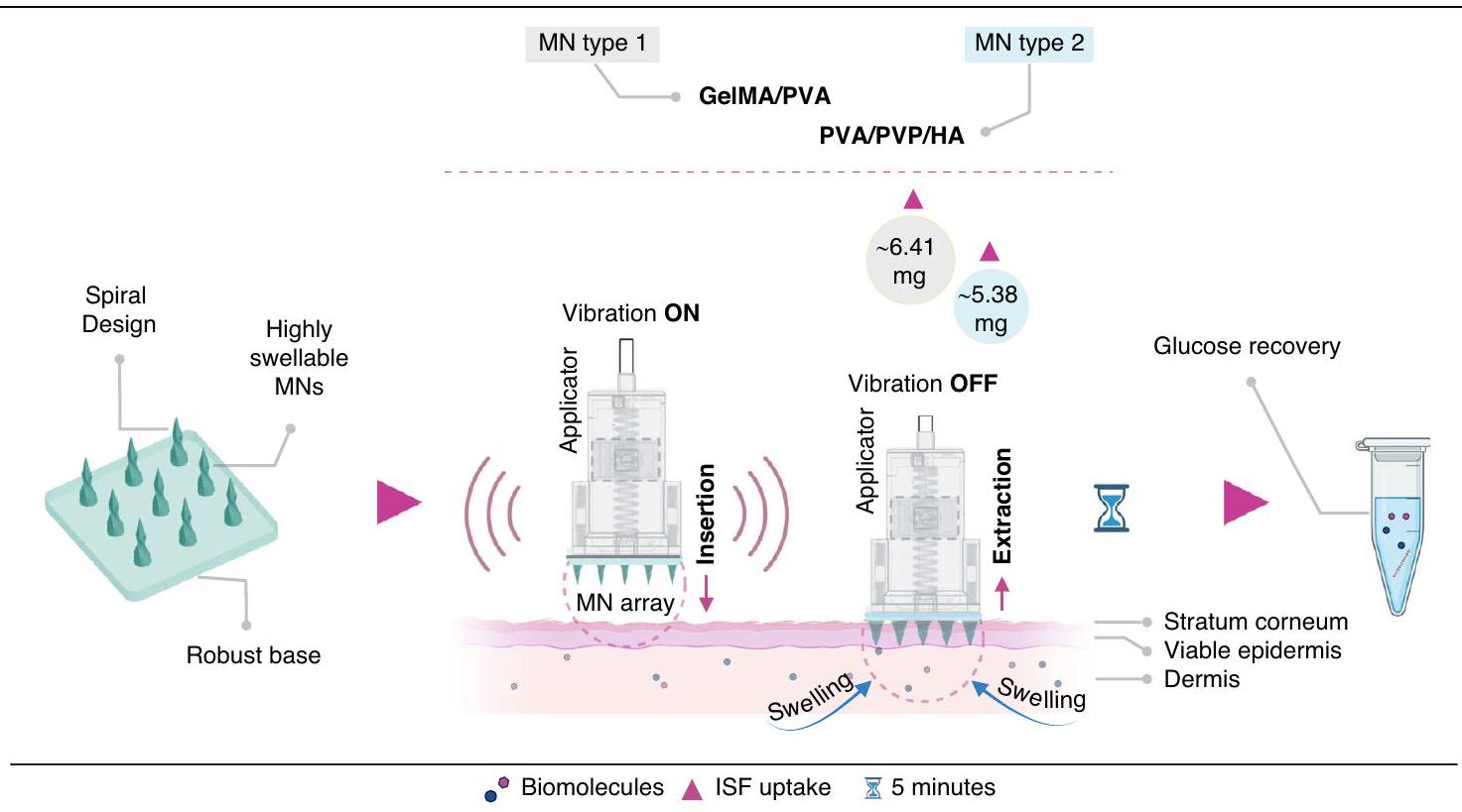
Therefore, there is a need for rapid ISF extraction and biomarker analysis. This study introduces two distinct types of cross-linked, dual-layer spiral structured MNs made of GelMA/PVA and PVA/PVP/HA hydrogels for rapid ISF extraction. To the author’s knowledge, the spiral-shaped MN configuration represents a novel design that has not been explored previously. The chosen hydrogel combinations (GelMA/PVA and PVA/PVP/HA) significantly enhanced the swelling behavior of the MNs compared to previous studies . This study further
analyzes the importance of a uniform base layer for effective MN penetration into the skin. Due to its flexibility, Polyethylene Glycol Diacrylate (PEGDA) is selected for the GelMA/PVA MN array base, while PVP is chosen for the PVA/PVP/HA MN array base. Optimal drying times for the PVP base are determined through a two-step approach, with GelMA MNs requiring a shorter drying time. This study further investigates the swelling and mechanical properties of the MNs to assess their capabilities in insertion into the skin and ISF extraction. Swelling tests are conducted in both PBS and artificial ISF, while compression tests are utilized to assess the mechanical characteristics of the MNs.
The study also introduces an advanced version of our patented MN applicator capable of inserting MNs at a velocity of with vibration ( ), developed by our group for the first time. The updated version of the applicator allows precise control over vibration during and immediately after insertion using two eccentric rotating mass (ERM) micro-vibration motors that can easily be controlled independently or in unison through the Arduino IDE. This supports the feasibility of micro-vibration-assisted ISF extraction, a novel technique developed in this study. The results indicated that in conjunction with various other factors (e.g., MN design, material properties, swelling behavior of the MN material), vibration-assisted insertion significantly improves penetration effects and enables more ISF extraction. Using this approach, GelMA/PVA and PVA/PVP/HA MN arrays are tested on porcine ear skin, extracting and of ISF in just 5 min . Furthermore, the successful recovery of various glucose concentrations is validated through in vitro agarose gel experiments using the GelMA/PVA and PVA/PVP/HA MN arrays. A schematic of minimally invasive rapid extraction of ISF and recovery of glucose using micro-vibration-assisted spiral MNs is presented in Fig. 1.

Results and discussion Spiral design

MNs were designed in a spiral pattern by incorporating two squares of 0.15 mm and 0.20 mm in the structure. The distance between the squares was 0.4 mm , and the tip and base of the needle were constructed as circles. MN initial design had a height of 1 mm , a tip diameter of 0.02 mm , a base diameter of 0.3 mm and the distance between the needles was set at 0.40 mm . The primary objective of adopting a spiral design was to provide interlocking capabilities for effective ISF extraction. This could be due to the increased number of vertices in the spiral design, which could aid in achieving a more stable penetration. This stability could reduce the likelihood of MN displacement during use. Moreover, the spiral form offers an increased surface area in contact with the skin
Fig. 1 Schematic illustration of minimally invasive ISF extraction and glucose recovery using highly swellable spiral MNs with the custom-made applicator to generate micro-vibration during the insertion phase
compared to traditional conical shapes. This could potentially enhance the efficiency of ISF extraction by providing a larger surface for the fluid to adhere to and be drawn out during the retraction of the MNs. In the current study, the MNs were fabricated with an anticlockwise twist, fixed upon insertion and did not allow rotation. The number of MNs per array was on a base plate of . The thickness of the MN array base was set to 1.25 mm , which provided sufficient support during the PDMS mold replication for the MN solution to be added without any additional steps required .

Fabrication of spiral MNs and optimization of base layers

This study used projection micro stereolithography (P SL) to print master MN arrays over a area. This advanced technology enables 3D printing of miniaturized parts with resolution and accuracy at scale. PuSL represents the link of two major technology trends: 3D printing and miniaturization. However, miniaturization is limited by the difficulty in prototyping and cost-effective manufacturing of the devices. PuSL is a stereolithography technique incorporating a digital light processing engine, precision optics, motion control, and advanced software. Stereolithography produces parts in layers using a photochemical process. A photosensitive liquid resin is exposed to light; consequently, polymeric cross-linking and solidification occur. A flash of UV light, 405 nm , causes the rapid photo-polymerization of an entire resin layer. Like other 3D printing processes, it uses a CAD file
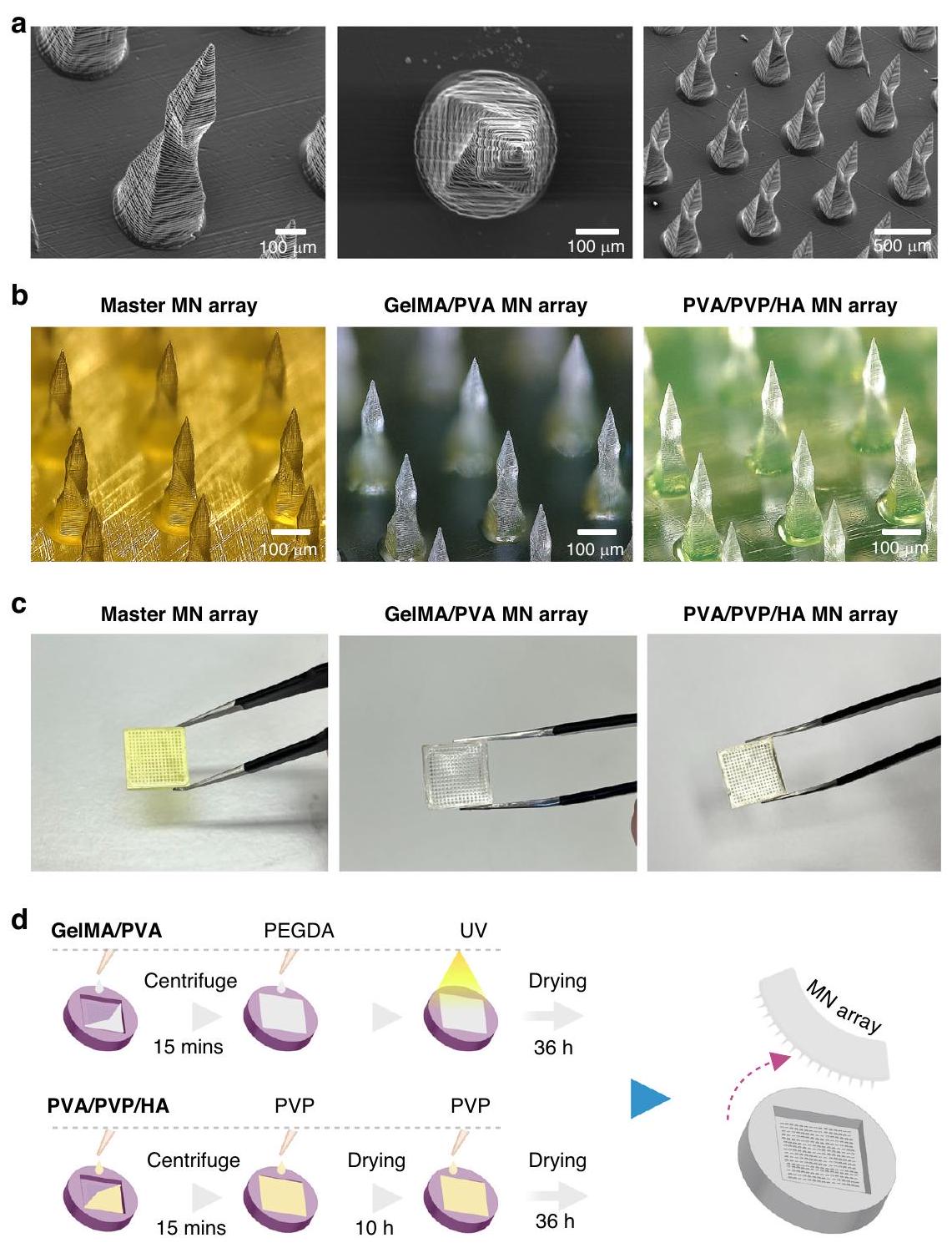
as an input and is then sliced into a series of 2D images called digital masks that show or hide specific areas of a layer. Each layer has a mask, and each layer is added until the entire 3D structure is complete. Slicing data was sent to the 3D printing system to fabricate individual layers. PuSL technology can achieve resolutions of several micrometers or hundreds of nanometers by controlling the projection lens. The master MN array was printed in high temperature resistance (HTL) material using this advanced technology.
After creating the master MN , it was used to create PDMS negative molds (Supplementary Fig. S1) to replicate GelMA/PVA and PVA/PVP/HA MN arrays. All MN replicas were formed without any defect, resembling the spiral shape of the master array, as shown in Fig. 2a; however, longitudinal shrinkage was observed across all MN types (master and replica) compared to their initial CAD dimension . The 3D printed master MNs shrank by longitudinally, which could be due to the 3D printing characteristics such as print speed and material exposure time during the print that can unevenly distort and lead to a higher overall shrinkage. The GelMA/PVA and PVA/PVP/HA MNs also showed shrinkage in height of and to the original CAD dimension, respectively. Compared to the 3D printed master MNs, these two types of MNs’ shrinkage were significantly lower at and , respectively. The master MNs had a sharp tip with a diameter of , whereas GelMA/PVA and PVA/PVP/HA
Fig. 2 Design and fabrication process of the spiral-shaped GeIMA/PVA and PVA/PVP/HA MNs. a SEM images showing the complex spiral structure of the MN (left), tip view (middle) and an array where MNs are distributed uniformly across the base (right). b Optical images ( tilt) of the master MNs 3D printed (left), GelMA/PVA (20/3, w/v) MN array with the base layer (middle) and 12/5/1, w/v) MN array with the base layer (right) in differential interference contrast mode. c The captured images of the master MN array (left), GelMA/PVA (20/3, w/v) array (middle) and PVA/PVP/HA MN (12/5/1, w/v) array (right) containing 225 MNs in each array. d Schematic representation of the fabrication process for GelMA/PVA and PVA/PVP/ HA MN arrays, showing centrifugation, UV curing, and drying steps leading to the final MN array
MNs had a tip diameter of and , respectively. These are well below , which is fundamental for successful insertion into the skin . This suggests the successful fabrication of polydimethylsiloxane (PDMS) molds and precise replication of the spiral geometry. In Fig. 2b, c, optical and captured images of MNs show consistent structural integrity among master, GelMA/PVA, and PVA/PVP/HA MNs. The spiral shape, as well as the viability and integrity of the tips, remains identical across these variants.
For precise insertion and ease of attachment of the MN arrays to the applicator, the base layer of the MN array should be reasonably flat and uniform, particularly for larger array sizes ( ). Lack of uniformity in the base may lead to insufficient penetration and effectiveness. For GelMA/PVA MNs, PEGDA was chosen as the base layer due to its flexible mechanical properties, which can be tuned by adjusting the amount of Irgacure and UV exposure time . This shared component (GelMA/PVA MNs and PEGDA base) facilitated a strong
bond, forming a cohesive, single-layer structure in the final MN array. However, the attempt to incorporate PEGDA into PVA/PVP/HA solutions as a base did not work as expected. For instance, PEGDA did not form a uniform layer with the PVA/PVP/HA solution. Due to its photoinitiator content, the PEGDA base hardened more rapidly when exposed to UV light than the PVA/PVP/HA solution, leading to inadequate bonding between the two layers. To address this, three tests were conducted: one with the combination of PVA/PVP ( ) and the other two with PVP ( ) and PVA ( ). Uniformity was observed in all formulations, but the duration of solution drying varied proportionally to the concentration of PVA or PVP. Considering that MNs would be dissolved in the buffer solution to recover the biomarker, it was challenging to dissolve PVA/PVP ( , . On the other hand, preparing PVA ( ) with a higher molecular weight ( 89 kDa ) proved to be a time-consuming process due to its exceptionally high viscosity. Therefore, PVP ( ) was considered the preferred solution for ease of preparation, lower viscosity, convenience for pipetting, and adequate bonding with PVA/PVP/HA MNs.
The drying time for the PVP base was optimized using a two-step strategy. Initially, of the PVA/PVP/HA solution was added into the molds and centrifuged to form the MNs, followed by an immediate overfill of PVP to form the base and drying for 10 h (Supplementary Fig. S2). Additional PVP was added and left to dry for another 24 h to develop a uniform MN base structure. Figure 2d illustrates the optimization process of the MN arrays and their base layer. It was noted that large variations in the optimal drying time resulted in uneven drying, with shrinkage occurring in the center while the corners remained rigid. GelMA MNs were dried for 36 h , after which they were successfully peeled off without further issues.

Swelling kinetics and PBS uptake in vitro

Swelling properties of the material play a pivotal role in determining the efficiency of swellable MNs in extracting ISF. MNs with enhanced swelling ratio are more likely to rapidly extract a higher volume of ISF within a shorter period ( min), which would benefit users by reducing the time required for ISF sampling and increasing the accuracy of diagnostic tests.
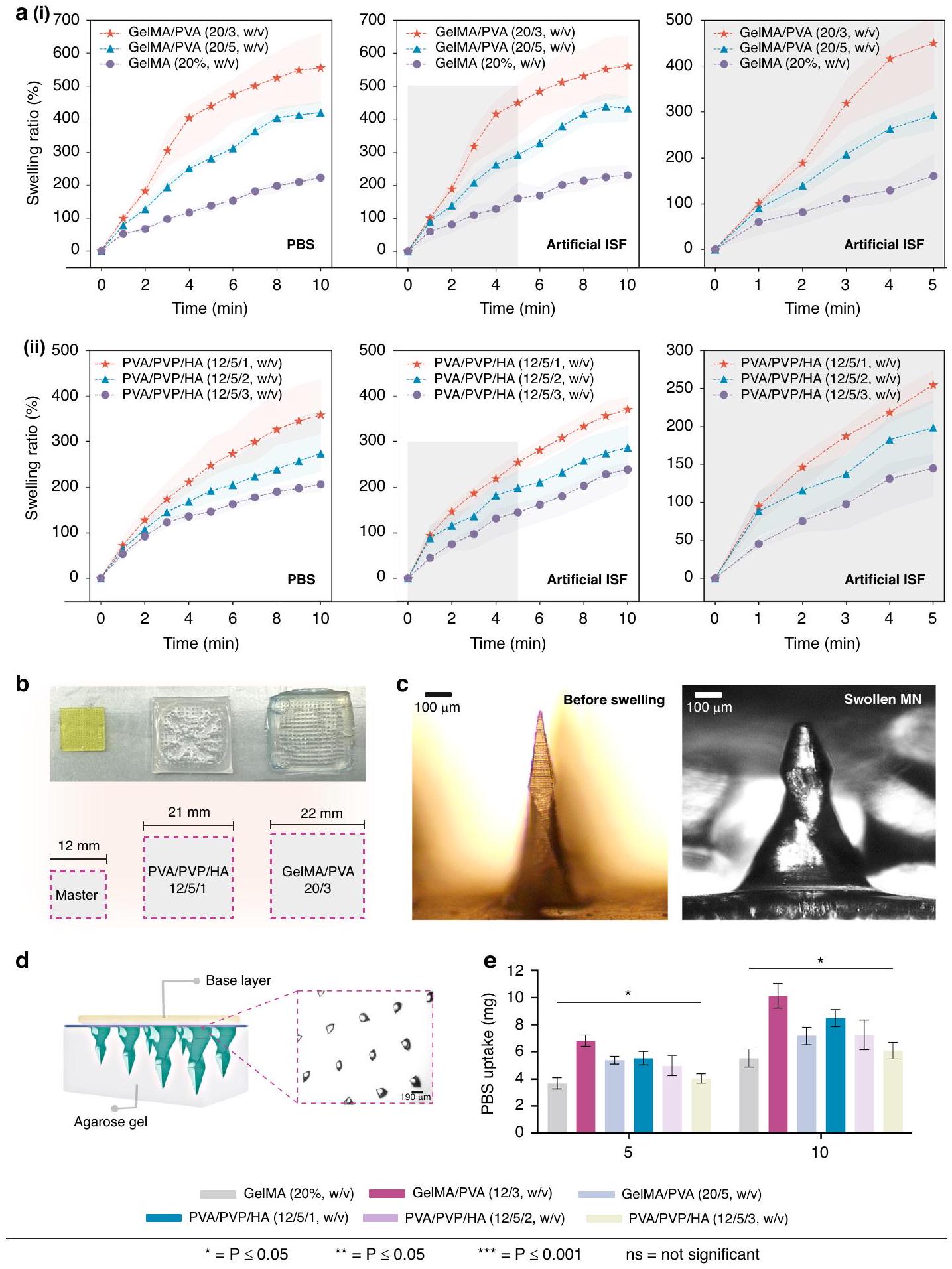
The swelling ratios of the MNs were conducted in artificial ISF and PBS (Phosphate-buffered Saline) for up to 10 min . The results in Fig. 3a(i-ii) demonstrated that the swelling ability of the MNs increases over time after immersion. In artificial ISF, GelMA ( , w/v) alone had a relatively lower swelling ratio of . However, the incorporation of and PVA increased the swelling to and ,
respectively, which are higher than similar reported studies . This enhanced swelling can be attributed to increased hydrophilic sites within the GelMA matrix. These results showed that increasing PVA concentration from to did not result in a linear improvement in swelling and formed a denser structure with reduced porosity. Therefore, this observation suggests that further increasing the PVA concentration will unlikely enhance the swelling of the GelMA/PVA MNs.
Further experiments were conducted with varying concentrations of PVA and PVP only. However, the obtained swelling ability of the MNs was not optimal (Supplementary Fig. S3). Therefore, HA was introduced, and three different concentrations of HA ( , w/ v) were prepared while maintaining the PVA and PVP concentrations at and , respectively. The variations in swelling ratios can be related to the different concentrations of HA. Introducing 1% (w/v) HA resulted in the highest swelling ratio of , indicating a direct influence to absorb the artificial ISF and remain intact. The increased swelling is likely due to the larger pore size of HA molecules, which allowed for greater ISF uptake. As the HA concentration increased to , a slightly lower swelling ratio of was observed. Notably, with a HA concentration, the swelling ratio further decreased to . Therefore, incorporating small amounts of HA can enhance the swelling behavior of the PVA/PVP hydrogel, but excessive HA could occupy a significant portion of the hydrogel network. This limits the capacity of the hydrogel MNs to absorb and retain fluid effectively.
Similar experiments were carried out in PBS for the swelling test. The MNs exhibited subtle differences in PBS compared to artificial ISF. For example, GelMA/PVA compositions showed a slightly higher swelling tendency when immersed in artificial ISF, compared to in PBS, possibly due to specific interactions with certain constituents present in ISF. PVA/PVP/HA compositions also exhibited lower swelling in PBS, , compared to in artificial ISF. This variation in swelling characteristics between the two different environments (artificial ISF and PBS) could be attributed to differences in the chemical composition and concentrations of the solvents. Although Swelling ability can be influenced by various factors (e.g., chemical composition of the hydrogel network and properties of the surrounding environment), the result suggested that the swelling ratio of these MNs is relatively consistent between PBS and artificial ISF.
Expansion and swelling of the MN arrays were also very noticeable visually. As the MNs swelled, they significantly increased in size, confirming their ability to effectively absorb PBS. The results indicated that the GelMA/PVA (20/3, w/v) MN array exhibited a substantial increase in
Fig. 3 Swelling behavior, morphology, and PBS uptake of GeIMA/PVA and PVA/PVP/HA MNs. a (i) Swelling rate of the GelMA/PVA MNs in PBS buffer (left) and artificial ISF (middle) at with the first 5 min in artificial ISF highlighted (right). a (ii) Swelling rate of the PVA/PVP/HA MNs in PBS buffer (left) and artificial ISF (middle) at with the first 5 min in artificial ISF highlighted (right). b A visual comparison of the MN arrays shows their increased size compared to the original master template. c Microscopic images of a single MN showing morphological changes before and after swelling in PBS buffer. d Schematic illustration of MNs penetration into agarose gel ( ) for in vitro swelling test. The micro-holes left by the MNs are shown in the closed-up section. e PBS uptake (mg) by the MNs after 5 and 10 min of swelling in agarose gel ( )
size, swelling to 1.7 times its original dimensions (master MN array). Similarly, the PVA/PVP/HA (12/5/1, w/v) MNs also demonstrated significant swelling, expanding to 1.8 times their initial size (master MN array). Both types of MNs showed exceptional ability to absorb PBS and increase in volume in 5 min, as shown in Fig. 3b, with the PVA/PVP/HA (12/5/1, w/v) MN array being slightly smaller in size compared to the GelMA/PVA ( ) MN array. Figure 3c shows the image of a MN before and after 5 min of swelling, which caused the MN to expand, resulting in a broader and less defined tip than its original shape.
Experiments were also conducted on the skin model constructed using agarose hydrogel to assess the PBS uptake capacity of MNs, as illustrated in Fig. 3d. A consistent pattern of increased PBS uptake was observed across various GelMA/PVA and PVA/PVP/HA compositions, as shown in Fig. 3e. Among them, GelMA/PVA exhibited the highest PBS uptake of , followed by and for GelMA/PVA (20/5,w/v) and GelMA , respectively. These results are higher than those reported in previous studies and align with the observed trend in swelling behavior . Based on the experimental results, GelMA/PVA (20/3, w/v) appeared most suitable for swellable MNs among similar compositions. The extracted amount of PVA/PVP/HA MNs varied depending on the ratio of PVP/PVP to HA. The highest PBS volume was obtained with PVA/PVP/HA , extracting from the agarose gel. Other compositions, such as PVA/PVP/HA (12/5/2, and PVA/PVP/HA (12/5/3, w/v), extracted and , respectively. These values also exceeded those reported in similar studies . Additionally, the PBS uptake ability of these MNs aligns with the swelling trend obtained earlier. Therefore, PVA/ PVP/HA (12/5/1, w/v) was chosen as the preferred solution for further assessments. A summary of all swelling test results on both PBS and artificial ISF at is provided in Supplementary Table S1.

Mechanical properties of the spiral MNs

Although skin penetration force can be influenced by age, gender, and race, studies have reported that a minimum fracture force of 0.058 N per needle is necessary to penetrate the skin successfully . This represents that a single MN must overcome the required fracture force to pierce through the outermost layer (SC), which is the primary barrier to penetration. Efficient extraction of ISF also requires MNs to withstand the skin barrier, SC, without breaking. Therefore, a compressive load test was conducted to assess the structural integrity of the spiral MNs. MN array ( ) was placed between the plates of a universal testing machine (UTM) to record the force-
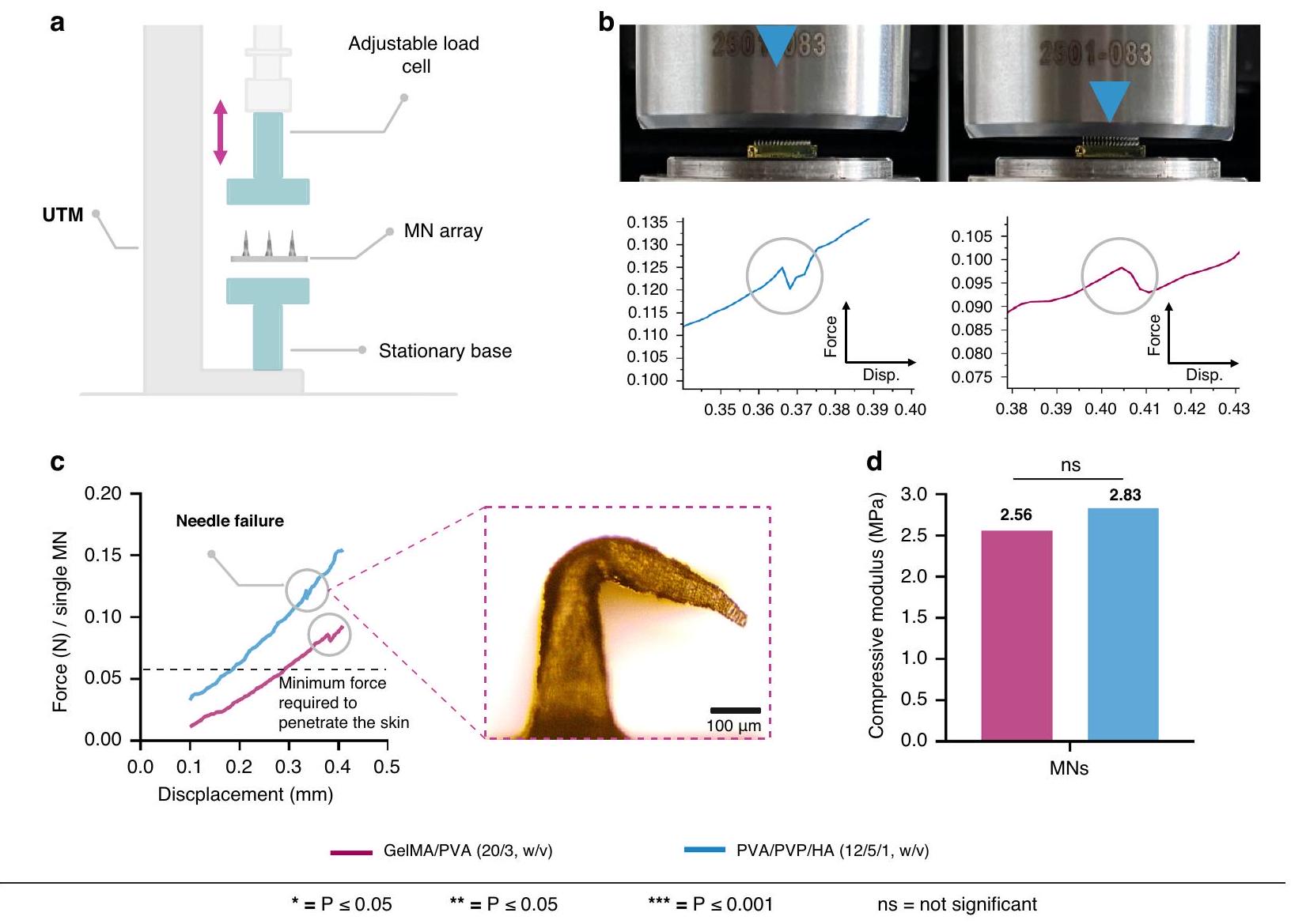
displacement curve, as illustrated in Fig. 4a. Although each array in the test had 225 MNs , the force measurement was calculated to represent a single needle in the force-displacement curves which provides critical insights into the mechanical behavior of the MNs. When the tip of the MN first contacts the upper plate of the UTM, the force increases to a peak, then drops to a low point before rising to a second peak. The initial peak indicates the failure load, resulting in permanent deformation of the MN structure. Figure 4b shows the impact of compression on the MN structure and their corresponding peaks as both types of MNs deform in the vertical direction.
For GelMA/PVA ( ), the compressive load applied to each MN was gradually increased from 0 to 0.18 N as the displacement reached 0.5 mm . The fracture force of the single MN was 0.11 N , which occurred at a displacement of 0.37 mm . For the PVA/PVP/HA (12/5/1, MNs, the compressive load reached 0.19 N by the end of the test, and the measured fracture force for a single MN was 0.13 N . This suggests that the mechanical strength of each PVA/PVP/HA (12/5/1, w/v) MN was higher than that of the GelMA/PVA (20/3, w/v) MNs, as indicated by their respective fracture forces compared to 0.11 N . Both fracture forces of the GelMA/PVA and PVA/PVP/HA MNs were significantly higher than the minimum force required to penetrate human skin. Specifically, the fracture force overcome by a single GelMA/PVA (20/3, w/v) MN was times higher than the required threshold, while that of each PVA/PVP/HA ( ) MN was times higher. These fracture forces are significantly higher than the required force ( needle) to penetrate human skin, as highlighted (dotted grey line) in Fig. 4c. Additionally, the compressive modulus for GelMA/PVA (20/3, was 2.56 MPa when the GelMA concentration remained fixed at with a cross-linking time of 250 sec . Meanwhile, the compressive modulus of PVA/ was 2.83 MPa when the Irgacure concentration was . Figure 4 d shows the differences in the respective compressive modulus values of the two MN types.
Many studies of MNs have demonstrated good mechanical properties using similar materials such as PVA/PVA, GelMA, and HA. For example, Zhu et al., reported that compressive modulus increased from to with the variation of GelMA concentration from to . Khatabi et al. reported MNs made of PVA/HA with a failure load of 0.59 N , ten times higher than the required force to penetrate the skin for the application of drug delivery . Xu et al., studied swellable PVA/PVP MNs by changing the PVA concentration that can uptake ISF without significant deformation of the MN tip . The
Fig. 4 Mechanical testing of the GeIMA/PVA and PVA/PVP/HA MNs. a Schematic illustration shows the setup of the UTM used for the compressive load test. The MN array is placed between a stationary base and an adjustable load cell that applies force while the force-displacement data is recorded. The testing setup with the MN arrays under the load cell. The force-displacement curves for each type of MN (PVA/PVP/HA on the left and GelMA/PVA on the right) show the point at which the MNs reach their fracture force, with a noticeable peak followed by a drop indicating needle failure. c Comparison of the force-displacement curves of a single MN between GelMA/PVA (20/3, w/v) and PVA/PVP/HA (12/5/1, w/v) compositions showing the needle failure points, peaks, and the dotted line represents the minimum force required to penetrate the skin ( 0.058 N ). Both MN types surpass this threshold, with PVA/PVP/HA showing a higher fracture force. The close-up section on the right shows the deformation of the MN during the compression test. d The Bar diagram shows the compressive modulus of the two types of MNs
GelMA/PVA (20/3, w/v) and PVA/PVP/HA (12/5/1, w/v) MNs reported in this study demonstrated robust mechanical properties compared to similar studies. It is important to note that MN strength can impact the ability to uptake ISF. Swellable MNs with sufficient strength to penetrate the skin can enhance the extraction volume of ISF. Increasing MN stiffness, however, reduces the size of pores within the structure and prolongs the time needed to uptake ISF. Therefore, a balance between mechanical strength and porosity must be considered during swellable MN array design and development.

Surface characterization

The surface properties of MNs are also crucial for their effectiveness in skin penetration, ISF extraction, and comfort during use. The roughness of MNs, referring to
the micro-scale variations in height across the surface, can influence interactions with the skin . A rough surface may hinder smooth penetration, requiring more force for skin penetration, which can increase pain sensitivity and potentially cause damage to both MNs and the skin.
MNs were assessed for surface roughness properties using Atomic Force Microscopy (AFM). The GelMA/ PVA ( ) MNs exhibited a roughness of , while the PVA/PVP/HA (12/5/1, w/v) MNs showed a lower roughness value of without any additional coatings, as shown in Fig. 5a, b. Since GelMA/PVA (20/3, w/v) is composed of different materials and had higher swelling (a more porous structure), this likely contributed to increase in surface roughness compared to the PVA/PVP/HA (12/ 5/1, w/v) MNs. It was also notable that GelMA/PVA (20/
Fig. 5 AFM images showing the surface topography of MNs. Surface profile with visible height variations and corrected peak force error for variations in tip-sample interactions of the GelMA/PVA b PVA/PVP/HA . AFM scan size:
3, w/v) appears to have more porous and variable topography, while PVA/PVP/HA (12/5/1, w/v) appears smoother with less height variation. Analyzing the roughness of the surface provides insightful details about MNs’ structure, with a smoother surface indicating a welloptimized fabrication and replication process.

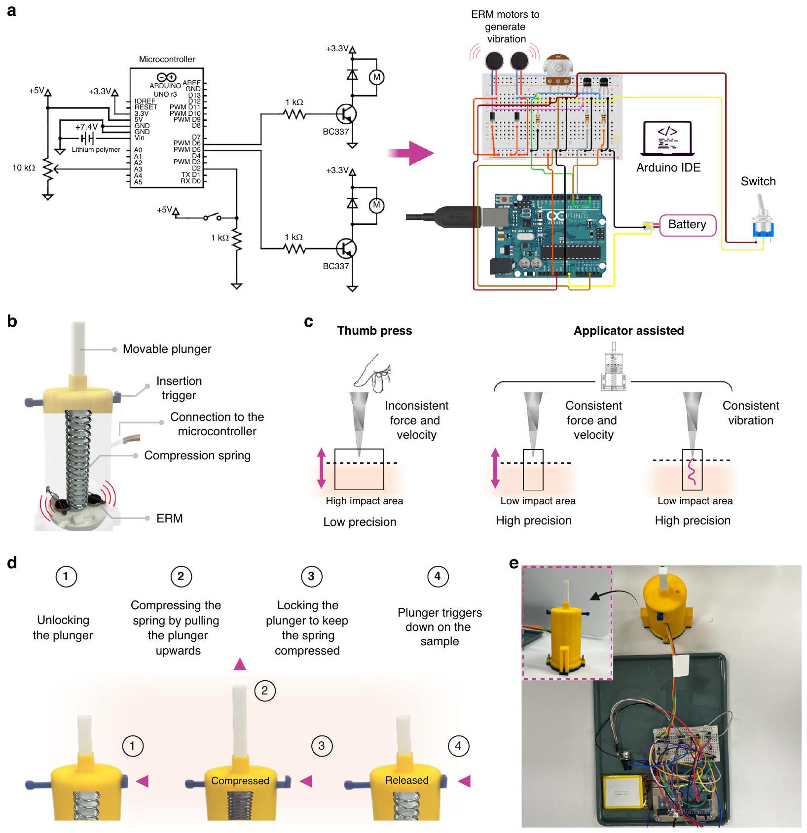
Micro-vibration assisted MNs insertion and ISF extraction MN applicator with arduino microcontroller

Our group has previously developed an MN applicator capable of generating vibrations at frequencies ranging from 50 to . This study has integrated the applicator with the Arduino platform to enhance its precision and control. Overall design parameters such as height, width or main body of the applicator remained unchanged and consistent with the previous design. However, significant optimizations were made to the circuit connections. Initially, the applicator featured a single-vibration motor (ERM or LRA). In the modified version, two single ERM motors were attached parallel to each other on the plunger, controlled and synchronized using the Arduino Integrated Development Environment (IDE), as shown in Fig. 6a. This setup created symmetrical vibrations across the plunger head, which led to a more uniform distribution of the vibration pattern. In contrast, placing just one motor on the side may result in uneven vibrations, with stronger effects closer to the motor and weaker effects farther away. ERM motors were preferred for their energy efficiency and low cost, producing primarily transverse vibrations. These were programmed via the Arduino IDE to manage the operations of the motors and precisely control the vibration frequency ( 50 Hz and 100 Hz ). This eliminated the need for manual tuning with a potentiometer knob, which can be imprecise and challenging to set accurately to the required frequencies or 100 Hz . This imprecision could lead to inconsistent outcomes, especially if the vibration frequency is not properly optimized.
The programming through the Arduino IDE enabled finer control than manual adjustments (potentiometer),
enhancing the system’s overall functionality. Despite this, a potentiometer was still incorporated as a backup control method, allowing for manual adjustments of the voltage applied to the ERM motors when necessary. This ensures that manual control can still be available if the Arduino IDE is not accessible. Therefore, two transistors were introduced to amplify the signal to the required voltage level. Diodes were also added to protect the transistors from reverse voltage spikes and maintain circuit stability. Furthermore, resistors were used to limit the current flowing through the transistors and motors, ensuring safe and efficient operation. When the Arduino reads signals from the potentiometer, it converts them to voltage, which then controls the vibration of the two ERMs, translating electrical signals into physical vibration. Figure 6b shows the mechanical design and internal configuration of the MN applicator. The insertion trigger initiates the action, while the compression spring provides the necessary force for the plunger to push the MNs into the skin.
One of the fundamental challenges for swellable MNs is the consistent and precise skin penetration, which is influenced by various factors such as the applied force, the velocity of insertion, and the mechanical properties of the . While the thumb press (manual application) method is simple and accessible, it may lead to uneven penetration depths and inconsistent results. Moreover, manual insertion produces inconsistent force and velocity, resulting in unpredictable high or low impact with low precision. Observations from biological systems, such as mosquitoes and honeybees, reveal that their proboscis insertion happens remarkably quickly . Moreover, mosquitoes use a combination of mechanical action and micro-vibrations to penetrate the skin efficiently with minimal discomfort . This highlights the natural effectiveness of velocity and vibration in efficiently penetrating skin surfaces. Therefore, the applicator was developed to address these challenges by offering significant benefits for skin insertion with minimal invasiveness. With its ability to control the impact applied, the applicator can
Fig. 6 MN applicator and its operational mechanisms of the design and functionality. a Schematic diagram of the electronic control system for the applicator, showing the connections between the microcontroller (Arduino Uno) connected with two ERM motors using a potentiometer, two transistors, two resistors, two diodes, a switch, and a battery. The switch enables vibration at 50 Hz or 100 Hz frequencies when activated. b Illustration of the internal configuration of the plunger mechanism with two ERMs for providing vibration, highlighting the insertion trigger, connection to the microcontroller, and compression spring. c Comparative biomechanics of thumb press versus applicator-assisted MN insertion methods, highlighting the differences in applied force, insertion velocity, and precision. d Step-by-step operational mechanism of the applicator from unlocking the plunger to triggering it down onto the sample. e Photograph of the assembled applicator configuration with an inset showing a close-up view of the custom-built applicator
provide greater precision in the MN application and ISF extraction effectiveness. Figure 6c highlights the skin biomechanics of applicator-assisted MN application compared to manual insertion.
The step-by-step operational mechanism of the applicator, which has a velocity of and vibrations of 50 and 100 Hz , is shown in Fig. 6d. The mechanism starts by unlocking the plunger, pulling it upward, compressing the
spring and storing potential energy. The plunger is then locked to maintain this compression. When triggered, the stored energy in the spring is released, driving the MNs into the skin sample with controlled force and precision. Figure 6e shows the actual physical setup of the applicator device connected to the electronic component for the MN insertion test.

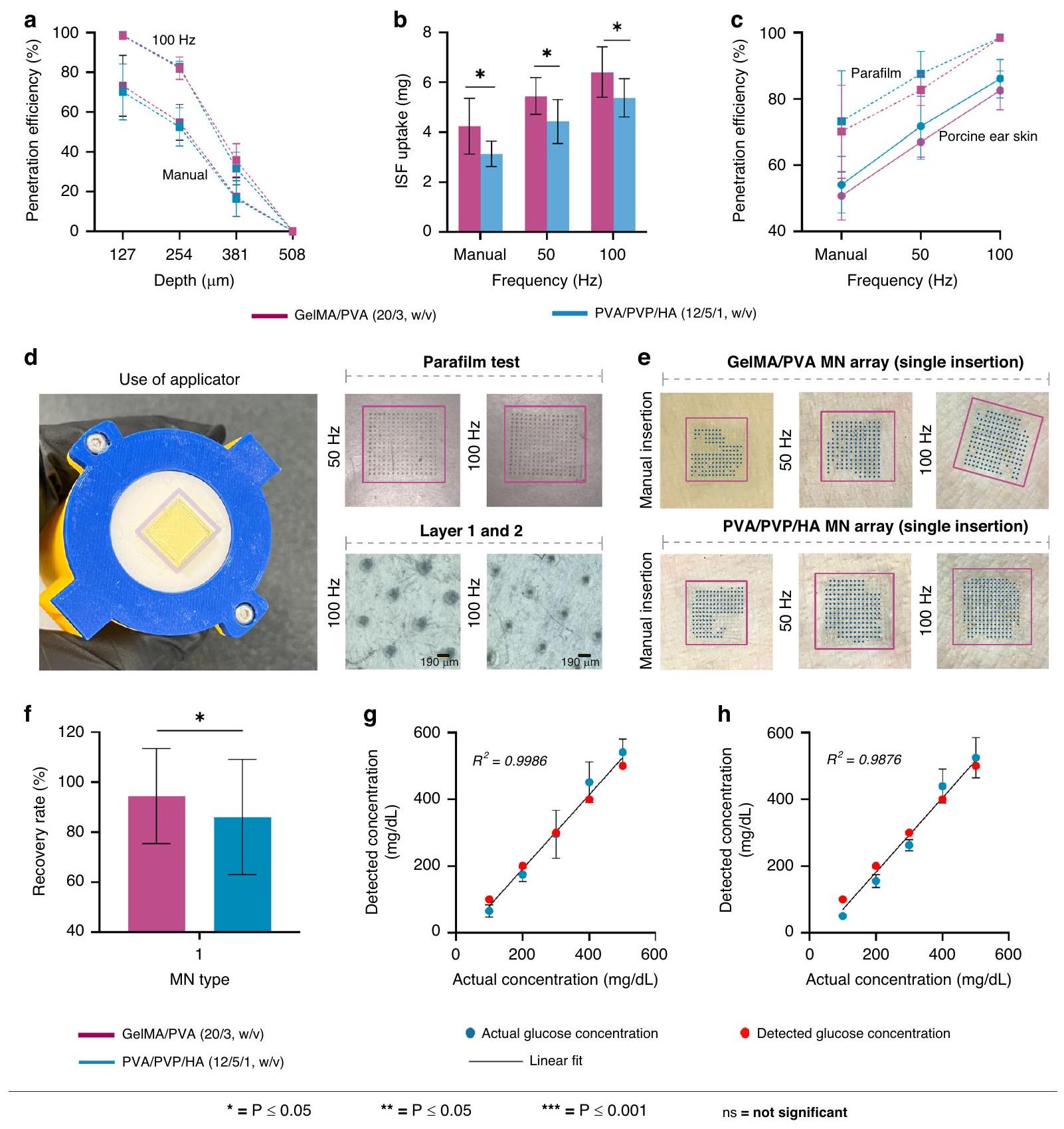
MNs insertion, ISF extraction, and glucose recovery

An initial parafilm test was performed to investigate the impact of micro-vibration on skin penetration. It involved manual insertion and applying vibration frequency at 50 Hz and 100 Hz on a 1.1 mm skin model comprising 8 layers of parafilm. The first layer of the parafilm is critical as it represents the initial interaction of the MNs with the . Testing on the first layer provides the most relevant information on how the MNs would perform on the skin.
The percentage of spiral MNs in an array which penetrated the skin model without vibration for the first layer was and for the GelMA/PVA (20/3, ) and PVA/PVP/HA (12/5/1, w/v) respectively. When vibration was introduced , GelMA/PVA , w/ v) MNs exhibited parafilm micro-hole distributions of , increasing the penetration efficiency on the first layer by . Similarly, for PVA/PVP/HA (12/5/1, MNs, the micro-hole percentages for the first layer were , which is a increase from the manual insertion. Results further showed that increasing the frequency from 50 Hz to 100 Hz significantly increased the penetration efficiency to and for GelMA/PVA ( ) and PVA/PVP/HA ( ), respectively. Although both types of MNs could penetrate multiple layers of parafilm, the number of holes decreased sequentially within each layer. It was also noted that the diameter of the holes in the parafilm on the first layer is larger than those on the second and third layers. Maximum penetration depth calculated for both MN types reached within parafilm, Fig. 7a. Considering the average thickness of the SC is , the results demonstrated that the applicator with vibration enhanced the penetration efficiency and produced more micro-holes on the skin model, which is a critical improvement from manual insertion and vital for the successful extraction of ISF. Because of the approach speed of the applicator, penetration to the full depth of occurs without multiple transverse vibrations of the MNs. However, during the post-insertion sprung contact time of a few seconds immediately following insertion, hundreds of vibrations occur (before the vibrations are turned off), which widen each of the MN pores with significant improvement of penetration efficiency and eventual fluid uptake.
Although the parafilm test provides valuable insights for analyzing the skin penetration capabilities of the MNs
before testing on biological samples (porcine ear skin), It has been reported to demonstrate higher penetration depths than those observed in porcine skin . Therefore, the insertion test of MNs was further studied on porcine ear skin to understand the difference between the use of vibration-enhanced and manual application (using thumb pressure). MN arrays were applied manually and with the custom-made applicator and 100 Hz at a speed of from a specific distance on the porcine ear skin. For GelMA/PVA ( ), penetration efficiency on the porcine ear skin with manual insertion and the applicator with vibration enhancement at 50 Hz and 100 Hz were , and , respectively. Result indicated a decrease of (manual), , and in penetration efficiency compared to the tests conducted on Parafilm. Similarly, For PVA/PVP/HA ( ) MNs, higher frequencies showed improved penetration rates with for manual insertion, at 50 Hz ), and at 100 Hz . However, there was also a decrease in penetration efficiency of for manual insertion, at 50 Hz , and at 100 Hz compared to Parafilm test results.
After MN arrays were manually applied for 5 min on the porcine ear skin, ISF uptake for GelMA/PVA (20/3, w/v) was only . However, using the applicator, the ISF uptake of GelMA/PVA increased to and for 50 Hz and 100 Hz , respectively. For PVA/PVP/HA ( ), thumb-pressed MN arrays extracted of ISF, while using the vibrationenhanced applicator improved the extraction to and for 50 Hz and 100 Hz respectively, Fig. 7b. As expected, the penetration efficiency at different vibration frequencies (manual, 50 Hz , 100 Hz ) was higher in parafilm compared to porcine ear skin, as shown in Fig. 7c. The correlation between penetration efficiency and the volume of ISF extracted is apparent as the higher penetration efficiency at and 100 Hz ) led to a higher volume of ISF uptake. The result indicated that at a frequency of 100 Hz , MNs exhibited a significantly higher penetration rate, creating a greater number of viable micro-holes and simultaneously widening each micropore in the porcine ear skin compared to parafilm, Fig. 7d, e. The reduced efficiency with manual pressing compared to applicator-assisted operation could be attributed to uneven force distribution across the MN array. Human fingers are less precise in maintaining consistent pressure, leading to variability in penetration efficiency and depth . The force distribution mechanism across skin structure during MN insertion, manual versus applicator-assisted, is shown in Supplementary Fig. S4.
The velocity of MN insertion is also a critical factor influencing skin resistance during penetration. Studies
Fig. 7 Assessment of the spiral MN’s insertion and extraction capabilities. a Penetration efficiency (%) at different parafilm depths (127, 254, 381, and ) under varying frequencies (manual and 100 Hz ). b The volume of ISF uptake (mg) from porcine ear skin at different frequencies (manual, 50 Hz , and 100 Hz ). c Comparison of the penetration efficiency (%) of the MNs across different frequencies (manual, 50 Hz , and 100 Hz ) between parafilm and porcine ear skin. d MN array attached to the applicator’s plunger head using a double-sided tape for the insertion tests on parafilm shows the impact of 50 Hz and 100 Hz frequencies on the uniformity in first and second parafilm layers for GelMA/PVA ( , w/v) MNs. e Micro-holes created by the MNs visible on the porcine ear skin at different frequencies (manual, 50 Hz , and 100 Hz ) f Bar diagram of the glucose recovery rate (%) for both MN types. The detected glucose concentrations by the GeIMA/PVA (20/3, w/v) MNs in agarose hydrogel (blue dots) versus the actual glucose concentration (red dots). The detected glucose concentrations by the PVA/PVP/HA MNs in agarose hydrogel (blue dots) versus the actual glucose concentration (red dots)
have shown that increasing the insertion velocity reduces the force required to penetrate the skin . This effect is particularly significant in viscoelastic materials like skin,
where higher velocities cause greater deformation, thereby lowering the skin’s fracture strength and enhancing skin penetration . This is an important aspect for
swellable MNs, which typically have lower mechanical strength than other types due to their swellability. Moreover, the dynamic nature of vibration allows MNs to overcome the skin’s natural viscoelastic resistance more effectively than a static application of force. The combination of velocity ( ) and vibration ( ) enables the swellable MNs to penetrate deeply into the skin with minimal push force. While manual pressing might theoretically apply more force, it also lacks the micropore-widening effect, leading to lower fluid uptake efficiency. Moreover, excessive pressure could potentially damage the MNs or cause discomfort. Therefore, a vibration frequency of 100 Hz achieved optimal outcomes for the test on porcine ear skin, enhancing both penetration efficiency and micropore widening, which together lead to improved ISF extraction.
Nonetheless, due to the swelling nature of the hydrogel MNs, their structure weakens upon penetrating the SC, making them less capable of enduring continuous vibration. The ability of MNs to withstand vibration-enhanced penetration of the SC is also related to mechanical strength of the MNs. Higher frequencies ( ) demand greater mechanical strength from the MNs in transverse motion while inserted in the SC for several seconds after insertion. Therefore, vibrations were discontinued during the ISF extraction process to avoid the dissolution of the MNs. The volume obtained by manual insertion is also variable and prone to inconsistencies due to randomly applied force, depth, and angle of penetration. This lack of precision can lead to uneven penetration depths and varying degrees of skin disruption, resulting in unreliable outcomes and suboptimal ISF collection. The applicator ensures that a consistent force and insertion speed ( ) is used and reduces variability between repetitive applications. This uniformity is crucial for achieving reliable and reproducible results in ISF extraction.
To assess the ability of MNs to recover biomarkers, glucose was chosen as the target biomolecule within the agarose gel matrix. The MN arrays were applied to the agarose matrix for 5 min , after which they were removed and dissolved at to recover the glucose. The results suggested that the volume of ISF extracted can influence the recovery rate of glucose, as shown in Fig. 7f. For example, recovery rate of GelMA/PVA ( ) and PVA/PVP/HA (12/5/1, w/v) MNs were and , respectively showed that the increase in volume of ISF uptake of GelMA/PVA (20/3, w/v) led to a higher glucose recovery rate compared to PVA/PVP/HA (12/5/1, w/v) MNs. Small volumes of ISF could contain significantly fewer glucose molecules, leading to increased variability and a higher likelihood of measurement errors. This can make it challenging to achieve accurate glucose readings, as the reduced number of glucose molecules
may fall below the sensitivity threshold of the glucose detection assay kit. The accuracy of our results is supported by the fact that the glucose detection kit used is highly sensitive, which comfortably detects the induced glucose concentrations of to . Additionally, the extracted ISF volumes exceeded for all MN types, which ensured a higher concentration of glucose within the ISF for the detection. A study has also shown that larger volumes of ISF provide more stable and accurate glucose detection, as they reduce the impact of local variations and potential contamination . The correlations showed that the detected glucose concentrations (blue dots) closely aligned with the actual concentrations (red dots) across the entire range, with the data points signifying a high level of accuracy ( for GelMA/PVA for PVA/PVP/HA (12/5/1, w/v).

Conclusion

Considering the findings presented, our research addresses some of the key issues and research gaps identified in previous literature concerning the successful extraction of ISF using MNs. It has been highlighted that two of the critical challenges are the sample volume and extraction time . While there are currently no set standards for ISF volume and extraction time, it is essential to recognize the potential risks associated with low ISF volume, as it may result in obtaining insufficient or no biomarkers. Additionally, maintaining a relatively short extraction time is essential for preserving the integrity of hydrogel MNs and ensuring successful ISF extraction. This research addressed these critical challenges by introducing innovative design, novel approaches, material optimization, and developing an efficient ISF extraction process using a custom-made applicator. These connections underscore the significance of the findings in contributing to advancements in MN technology for improved, accurate and practical diagnostics and therapeutic responsiveness.
The performance of MNs in extracting ISF is influenced by several factors, including their design, material, swelling ability, mechanical characteristics, and insertion technique. Therefore, one of the objectives of this study was to investigate using only GelMA as the MN material and assess its ability to extract a higher volume of ISF within a short timeframe ( ). Previous research suggests that while GelMA and GelMA-based MNs can extract ISF, volumes typically remain below , and extraction times often exceed 10 min . Therefore, we introduced PVA as an additional hydrophilic polymer within the GelMA matrix to improve the extraction volume of ISF. The introduction of PVA aimed to explore and enhance the swelling properties of MNs. A comprehensive analysis was conducted by varying the PVA
yield of 5.8 g from the initial 10 g . The prepolymer was stored at before use.

Degree of substitution of GelMA

The methacrylamide groups in GelMA were quantified at by a high-resolution NMR spectrometer (Bruker Avance III 500 MHz , Bremen, Germany). GelMA and Gelatin samples were prepared by dissolving 40 mg GelMA or gelatine in . The degree of substitution (DS) of methacrylamide on gelatine (Supplementary Fig. S5) was calculated using the integrals of lysin methylene protons of GelMA and gelatine using the following equation:

Fabrication of GeIMA and GeIMA/PVA MNs

Three different solutions were prepared in PBS for MN arrays replication: GelMA (20%, w/v), GelMA/PVA (20/3, w/ v) and GelMA/PVA (20/5, w/v). The porous GelMA prepolymer was initially added to PBS at until fully dissolved. The aqueous GelMA solution was then mixed with the photoinitiator Irgacure ( ) at to prepare the GelMA solution. Separately, PVA (Mw 30 kDa ) was dissolved in PBS at two concentrations ( 3 and , w/v) under continuous stirring at overnight. Subsequently, GelMA ( ) was added to each homogeneous PVA solution at and stirred for 4 h . Irgacure ( ) was then added, and the mixture was placed in an ultrasonic bath at for 15 min . The prepared solutions were cast into the MN molds and centrifuged at 4000 rpm for 10 min to fill the MN molds cavities. MN molds were then exposed to UV light for 250 s . The cross-linked molds were dried in the dark at before being peeled off for further use.

Fabrication of PVA/PVP/HA MNs

PVA (Mw ) was dissolved at for 2 h in PBS under continuous stirring. PVP ( Mw 40 kDa , ) was also dissolved using the same method, while different concentrations of HA (Mw 300 kDa ) were prepared separately at , and , w/v. PVP ( Mw 40 kDa , ) was dissolved in Milli-Q water at for an hour to create the base solution. Then, PVA/PVP/HA solutions were set by accurately combining the pre-made PVA, PVP, and HA solutions. This was followed by adding a small amount of crosslinker glutaraldehyde to the reaction mixture at for 1 h . The PVA/PVP/HA solution was pipetted into the MN molds and centrifuged at 4000 rpm for 10 min to ensure complete penetration into the molds cavities. To form a robust MN base, the molds were lightly overfilled twice periodically with the base solution PVP ( ). The filled molds
were dried at or 36 h before being peeled off for further use.

Arduino-based custom-made applicator

The custom-made applicator was printed using a 3D printer (Teirtime , Teirtime Corporation, USA) with polylactic acid filament with a similar geometry described in our group’s previous work . The updated version of the applicator is equipped with the Arduino Uno microcontroller to control the system, which includes ERM vibration motors, a diode rectifier, a lithium polymer battery, a potentiometer, a transistor, and a resistor. The frequency range was directly adjusted between 50 and 100 Hz using the Arduino IDE.
The knob controlling the speed of the groove plunger was set to with an impact energy of 215.46 mJ . A push-button mechanism triggered the plunger head (with attached MN arrays) to impact the sample (Parafilm and porcine ear skin) while the vibration ( 50 Hz or 100 Hz ) was introduced using the Arduino IDE. The impact velocity of the prototype was validated using two techniques: high-speed camera analysis and theoretical modeling, as determined in our prior study .

Swelling ratios of the MNs in PBS and artificial ISF

The swelling ratios of MNs were assessed by measuring changes in mass before and after being submerged in both PBS and artificial ISF solution. MN array samples were submerged in PBS and artificial ISF at to determine the difference between wet weight ( ) and dry weight ( ) at different time points ( ). The objective was to observe the early stages ( ) of swelling ratios and analyze the trend over time by monitoring the mass changes at relatively short intervals ( 1 min ). The swelling ratio of the MNs was calculated using the following equation:

Determination of mechanical properties

Mechanical properties of the MNs were assessed by compression tests using a low-force UTM (Instron 3343, Instron, MA, USA). For each test, a MN array ( ) was placed needle-side up on the fixed plate of the UTM using a double-sided tape and compressed at a rate of up to a maximum downward height of 0.5 mm with a 50 N static load cell. The primary failure mode recorder was buckling with no significant torsional effects or additional twisting at failure. Force vs displacement was recorded to calculate the compressive modulus from the strain and stress curve with
the following equations:
Where is the applied compressive force (N), is the cross-sectional area of the MN array where the compressive force is applied ( ), is the set rate of the load cell of the UTM, is time of elastic deformation and is an approximate time when the load cell first reaches the MNs.

Morphology characterization

Images of the spiral MN arrays (master and replicas) were captured using a digital microscope (DSX1000, Olympus, Japan) at different magnifications ( ). The imaging was conducted with adjustable tilt angles ranging from to .
The spiral morphology of the MNs was assessed using a scanning electron microscope (SEM, JSM-7001F, JEOL, Japan). The MNs were sputter-coated with a 12 nm thick layer of platinum to prevent charging. The sample was then imaged in the field emission SEM at an accelerating voltage of 10 kV in high vacuum mode (HighVac) with a magnification level of . MN arrays were carefully demolded just before the imaging to prevent any potential damage.

Surface characterizations

Atomic force microscopy (AFM, Multimode 8-HR Nanoscope System, Bruker, CA, USA) was used in ScanAsyst mode to map the surface topography of the MNs. Silicon cantilevers (ScanAsyst Air, Bruker AFM Probes, CA, USA) featuring spring constants within the range of and resonance frequencies between were used for the measurements. For sample preparation, GelMA/PVA (20/3, w/v) and PVA/PVP/HA (12/5/1, w/v) solutions were individually deposited into pre-made circular blocks ( 10 mm diameter) and subsequently dried for 36 h at prior to testing. The scanning parameters were configured with a scan size of 500 nm at 2 Hz . The post-image analysis was conducted offline using the NanoScope Analysis software (Bruker, CA, USA).

Insertion test and extraction of ISF ex vivo

A commercially available Parafilm sheet was stacked into eight layers ( per layer, combined ) to simulate human skin for the initial insertion test. MN
arrays were applied to the simulated skin setup both manually and using the custom-made applicator at frequencies of 50 Hz and 100 Hz . After insertion, the microvibration process was stopped after a few seconds during which micropore widening occurred, after which the MN arrays were left in place for 30 s before being removed. The holes in the Parafilm layers were then examined under a microscope (Carl Zeiss Axio, Jena, Germany) to assess the efficiency of insertion.
Freshly slaughtered porcine ear skin was sourced from a local butcher (Brisbane, Australia) and stored in aluminum foil at until used. Before MN array insertion, the skin was cleaned with ultra-pure water and thawed in PBS for 2 h at . The thickness of the sample was measured at . Initially, the MN array was directly applied to the porcine ear skin without using the custom-made applicator. Subsequently, the MN arrays were inserted using the applicator at a speed of , with vibration applied solely during the insertion process and a few seconds afterwards at 50 Hz and 100 Hz frequencies. However, no vibration was applied during the ISF extraction phase. The array was left in place for 5 min before being removed. The obtained ISF volume was determined by subtracting the initial weight of the array ( ) from the weight measured after extraction ( ). Trypan blue ( ) was used to identify and stain the skin and incubated for 5 min to capture optical images.

Detection of glucose concentration in vitro

A 3% (w/v) agarose hydrogel was prepared with varying glucose concentrations: 100, 200, 300,400 , and dL. To detect the glucose concentration by MN arrays, the array’s dry weight ( ) and wet weight ( ) were measured after being inserted into the agarose gel containing different glucose concentrations for 10 min in each test. After insertion, the MNs were carefully removed from the array and placed in centrifuge tubes containing 1 ml of PBS ( pH 7.4 ). The tubes were heated at for 15 min to release glucose. Absorbance was measured at 540 nm by a UV-vis spectrophotometer (Shimadzu, UVmini1240, Japan) and quantified using a commercial glucose assay kit. Glucose concentration detected ( ) by the MN arrays were determined using the following formula:
Where glucose concentration from the standard curve using the assay kit, volume of the PBS added into the centrifuge tube wet mass of the MN array, dry mass of the MN array, density of the glucose extracted by the MNs .

Statistical analysis

The statistical analysis of the data was performed using one-way ANOVA, with significance levels denoted by asterisks: * for , ** for , and *** for . Origin Pro 2022 and Python were used for all statistical calculations. The data are presented as the mean ± standard deviation from five independent experiments .

Acknowledgements

This work used the Queensland node of the NCRIS-enabled Australian National Fabrication Facility (ANFF). The work undertaken would not have been possible without the generous support of AXT Pty Ltd. Specific acknowledgement goes to Jaret Lee and Bradman Marks from AXT for their assistance in microfabrication using a state-of-the-art projection micro stereolithography (PuSL) system from Boston Micro Fabrication. Special thanks to Vahid Ebrahiminejad for preparing the initial PVA/PVP solutions. This research received no specific grants from public, commercial, or not-for-profit funding agencies.

Author details

School of Engineering, University of Southern Queensland, Springfield, QLD 4300, Australia. Centre for Future Materials, Institute for Advanced Engineering and Space Sciences, University of Southern Queensland, Springfield, QLD, Australia. School of Engineering, University of Birmingham, Birmingham B15 2TT, UK. Oxacus Ltd, Dorchester-on-Thames OX10 7HN, UK. Faculty of Engineering, UNSW Australia, Sydney, NSW 2052, Australia. College of Engineering & Physical Sciences, School of Engineering, University of Birmingham, Birmingham B15 2TT, UK

Author contributions

K.M.S. and Z.FR. conceived the idea of the paper. K.M.S. performed the experiments and data analysis. K.M.S. and A.M. conducted the GelMA synthesis. K.M.S. wrote the paper, and P.A. assisted. P.D.P. and G.J.D. guided and reviewed the work. Z.FR. guided, reviewed and supervised the study. All authors contributed to the general discussion and approved the final manuscript.

Conflict of interest

The authors declare no competing interests.
All experiments involving animal products were conducted with the approval of the Animal Ethics Committee at the University of Southern Queensland, Australia (Ethics Approval Number: 23BIOS008).
Supplementary information The online version contains supplementary material available at https://doi.org/10.1038/s41378-024-00850-x.
Received: 10 July 2024 Revised: 26 October 2024 Accepted: 21 November 2024
Published online: 08 January 2025

References

  1. Lee, B. H., Shirahama, H., Cho, N. J. & Tan, L. P. Efficient and controllable synthesis of highly substituted gelatin methacrylamide for mechanically stiff hydrogels. RSC Adv. 5, 106094-106097 (2015).
  2. Heikenfeld, J. et al. Accessing analytes in biofluids for peripheral biochemical monitoring. Nat. Biotechnol. 37, 407-419 (2019).
  3. Sriram, S. Study of needle stick injuries among healthcare providers: evidence from a teaching hospital in India. J. Fam. Med. Prim. Care 8, 599-603 (2019).
  4. Serafin, A., Malinowski, M. & Prażmowska-Wilanowska, A. Blood volume and pain perception during finger prick capillary blood sampling: are all safety lancets equal? Postgrad. Med. 132, 288-295 (2020).
  5. Biswas, J. et al. Effect of Hypodermic Needle Versus Safety Lancet on the Fear and Anxiety of Needle Prick Among Undergraduate Medical Students During
Hematology Practical: A Cohort Study From a Resource-Limited Setting. Cureus 14, e27458 (2022).
6. McMurtry, C. M. et al. Far from “Just a Poke”: common painful needle procedures and the development of needle fear. Clin. J. Pain. 31, S3-S11 (2015).
7. Raju, K. S. R., Taneja, I., Singh, S. P. & Wahajuddin Utility of noninvasive biomatrices in pharmacokinetic studies. Biomed. Chromatogr. 27, 1354-1366 (2013).
8. Brinkman, J. E., Dorius, B. & Sharma, S. Physiology, Body Fluids. [Updated 2023 Jan 27]. In: StatPearls [Internet]. Treasure Island (FL): StatPearls Publishing; 2024 Jan-. Available from: https://www.ncbi.nlm.nih.gov/books/NBK482447/.
9. Elhassan E. A. & Schrier R. W. Comprehensive Clinical Nephrology: Fourth Edition, 85-99 (2010).
10. Wiig, H. & Swartz, M. A. Interstitial fluid and lymph formation and transport: physiological regulation and roles in inflammation and cancer. Physiol. Rev. 92, 1005-1060 (2012).
11. Mathew, J., Sankar, P. & Varacallo, M. Physiology, Blood Plasma. 2023 Apr 24. In: StatPearls [Internet]. Treasure Island (FL): StatPearls Publishing; 2024 Jan-.
12. Sagedal, S. et al. Intermittent saline flushes during haemodialysis do not alleviate coagulation and clot formation in stable patients receiving reduced doses of dalteparin. Nephrol. Dial. Transpl. 21, 444-449 (2006).
13. Müller, A. C. et al. A comparative proteomic study of human skin suction blister fluid from healthy individuals using immunodepletion and ITRAQ labeling. J. Proteome Res. 11, 3715-3727 (2012).
14. Reusch, M. K., Mansbridge, J. N., Nickoloff, B. J. & Morhenn, V. B. Immunophenotyping of skin cells during healing of suction blister injury. Dermatology 183, 179-183 (1991).
15. Bruschi, M. L. Strategies to modify the drug release from pharmaceutical systems. 1-199 (Woodhead Publishing, Elsevier, 2015). https://doi.org/10.1016/ C2014-0-02342-8.
16. Saifullah, K. M. & Faraji Rad, Z. Sampling dermal interstitial fluid using microneedles: A review of recent developments in sampling methods and microneedle-based biosensors. Adv. Mater. Interfaces 10, 2201763 (2023).
17. Ma, S., Li, J., Pei, L., Feng, N. & Zhang, Y. Microneedle-based interstitial fluid extraction for drug analysis: advances, challenges, and prospects. J. Pharm. Anal. 13, 111-126 (2023).
18. Gill, H. S., Denson, D. D., Burris, B. A. & Prausnitz, M. R. Effect of microneedle design on pain in human volunteers. Clin. J. Pain. 24, 585-594 (2008).
19. Rad, Z. F., Prewett, P. D. & Davies, G. J. An overview of microneedle applications, materials, and fabrication methods. Beilstein J. Nanotechnol. 12, 1034-1046 (2021).
20. Zhang, X., Zhang, W., Wu, W. & Chen, J. Programmable SARS-CoV-2 mutation detection platform based on ligation-triggered isothermal exponential amplification coupled with self-priming amplification. Microchem. J. 195, 109477 (2023).
21. Yoon, H. J. et al. Cold water fish gelatin methacryloyl hydrogel for tissue engineering application. PLoS ONE 11, e0163902 (2016).
22. Doğan, E. E. et al. Synthesis, characterization and some biological properties of PVA/PVP/PN hydrogel nanocomposites: antibacterial and biocompatibility. Adv. Mater. Sci. 19, 32-45 (2019).
23. Shi, Y., Xiong, D., Liu, Y., Wang, N. & Zhao, X. Swelling, mechanical and friction properties of PVA/PVP hydrogels after swelling in osmotic pressure solution. Mater. Sci. Eng.: C. 65, 172-180 (2016).
24. Sun, M. et al. Synthesis and properties of gelatin methacryloyl (GelMA) hydrogels and their recent applications in load-bearing tissue. Polymers 10, 1290 (2018).
25. Teodorescu, M., Bercea, M. & Morariu, S. Biomaterials of PVA and PVP in medical and pharmaceutical applications: perspectives and challenges. Biotechnol. Adv. 37, 109-131 (2019).
26. Zhu, J. et al. Phase segregated Pt-SnO2/C nanohybrids for highly efficient oxygen reduction electrocatalysis. Small 16, 1905910 (2020).
27. . et al. Swellable PVA/PVP hydrogel microneedle patches for the extraction of interstitial skin fluid toward minimally invasive monitoring of blood glucose level. Analyst 147, 1478-1491 (2022).
28. Fonseca, D. F. S. et al. Swellable gelatin methacryloyl microneedles for extraction of interstitial skin fluid toward minimally invasive monitoring of urea. Macromol. Biosci. 20, 2000195 (2020).
29. Chang, H. et al. A swellable microneedle patch to rapidly extract skin interstitial fluid for timely metabolic analysis. Adv. Mater 29, 1702243 (2017).
30. Ebrahiminejad, V., Rad, Z. F., Prewett, P. D. & Davies, G. J. Fabrication and testing of polymer microneedles for transdermal drug delivery. Beilstein J. Nanotechnol. 13, 629-640 (2022). 13:55.
31. Römgens, A. M., Bader, D. L., Bouwstra, J. A., Baaijens, F. P. T. & Oomens, C. W. J. Monitoring the penetration process of single microneedles with varying tip diameters. J. Mech. Behav. Biomed. Mater. 40, 397-405 (2014).
32. Han, W. T. et al. Improved cell viability for large-scale biofabrication with photo-crosslinkable hydrogel systems through a dual-photoinitiator approach. Biomater. Sci. 8, 450-461 (2019).
33. He, R. et al. Carbon nanotubes: construction of aptamer-siRNA chimera/PEI/5FU/Carbon nanotube/collagen membranes for the treatment of peritoneal dissemination of drug-resistant gastric cancer. Adv. Healthc. Mater. 9, 1901201 (2020).
34. Luo, Z. et al. Organ-on-a-Chip: organ-on-a-chip for cancer and immune organs modeling. Adv. Healthc. Mater. 8, 1801054 (2019).
35. Himawan, A. et al. Multifunctional low temperature-cured PVA/PVP/citric acidbased hydrogel forming microarray patches: Physicochemical characteristics and hydrophilic drug interaction. Eur. Polym. J. 186, 111836 (2023).
36. Makvandi, P. et al. Engineering microneedle patches for improved penetration: analysis, skin models and factors affecting needle insertion. Nano-Micro Lett. 13, 1 (2021).
37. Davis, S. P., Landis, B. J., Adams, Z. H., Allen, M. G. & Prausnitz, M. R. Insertion of microneedles into skin: measurement and prediction of insertion force and needle fracture force. J. Biomech. 37, 1155-1163 (2004).
38. Malek-Khatabi, A., Faraji Rad, Z., Rad-Malekshahi, M. & Akbarijavar, H. Development of dissolvable microneedle patches by CNC machining and micromolding for drug delivery. Mater. Lett. 330, 133328 (2023).
39. Nair, K. et al. Investigation of plasma treatment on micro-injection moulded microneedle for drug delivery. Pharmaceutics 7, 471-485 (2015).
40. Ebrahiminejad, V., Malek-khatabi, A. & Faraji Rad, Z. Influence of low-frequency vibration and skin strain on insertion mechanics and drug diffusion of PVA/ PVP dissolving microneedles. Adv. Mater. Technol. 9, 2301272 (2024).
41. Ling, J. et al. Critical roles of CX3CR1(+) mononuclear phagocytes in maintaining gut-liver axis health. J. Bionic Eng. 13, 303-304 (2016).
42. Aoyagi, S., Izumi, H. & Fukuda, M. Biodegradable polymer needle with various tip angles and consideration on insertion mechanism of mosquito’s proboscis. Sens. Actuators A Phys. 143, 20-28 (2008).
43. Kundan, K. K., Laha, S. & Ghatak, A. Vibration assisted puncturing of a soft brittle solid. Extrem. Mech. Lett. 26, 26-34 (2019).
44. Larrañeta, E. et al. A proposed model membrane and test method for microneedle insertion studies. Int. J. Pharm. 472, 65-73 (2014).
45. Czekalla, C., Schönborn, K. H., Lademann, J. & Meinke, M. C. Noninvasive determination of epidermal and stratum corneum thickness in vivo using two-photon microscopy and optical coherence tomography: impact of body area, age, and gender. Ski. Pharm. Physiol. 32, 142-150 (2019).
46. Alrimawi, B. H., Lee, J. Y., Ng, K. W. & Goh, C. F. In vitroevaluation of microneedle strength: a comparison of test configurations and experimental insights. RSC Pharm. 1, 227-233 (2024).
47. Leone, M. et al. Universal Applicator for Digitally-Controlled Pressing Force and Impact Velocity Insertion of Microneedles into Skin. Pharmaceutics 10, 211 (2018).
48. Kim, J. et al. Bioinspired microneedle insertion for deep and precise skin penetration with low force: why the application of mechanophysical stimuli should be considered. J. Mech. Behav. Biomed. Mater. 78, 480-490 (2018).
49. Mahvash, M. & Dupont, P. E. Mechanics of dynamic needle insertion into a biological material. IEEE Trans. Biomed. Eng. 57, 934-943 (2010).
50. Mahvash, M. & Dupont, P. E. Fast needle insertion to minimize tissue deformation and damage. IEEE Int. Conf. Robot. Autom. 2009, 3097-3102 (2009).
51. Steil, G. M. et al. Interstitial fluid glucose dynamics during insulin-induced hypoglycaemia. Diabetologia 48, 1833-1840 (2005).

  1. Correspondence: Zahra Faraji Rad (Zahra.FarajiRad@usq.edu.au)
    School of Engineering, University of Southern Queensland, Springfield, QLD 4300, Australia
    Centre for Future Materials, Institute for Advanced Engineering and Space Sciences, University of Southern Queensland, Springfield, QLD, Australia Full list of author information is available at the end of the article