إلكتروليت ذو قدرة ضعيفة على الحل في البطاريات القابلة لإعادة الشحن من أيونات الزنك المائية العملية A weakly solvating electrolyte towards practical rechargeable aqueous zinc-ion batteries
إلكتروليت ذو قدرة ضعيفة على الحل في البطاريات القابلة لإعادة الشحن من أيونات الزنك المائية العملية
تاريخ الاستلام: 20 أبريل 2023 تم القبول: 22 ديسمبر 2023 نُشر على الإنترنت: 05 يناير 2024 (أ) التحقق من التحديثات
شين شيجينهاو شياجين وانغشيلينغ شيازوجين يانغو شيهونغ لو
الملخص
تدهور الهيكل والتفاعل الجانبي، الذي نشأ من المذاب، هي القيود الرئيسية لنشر كل من الكاثود والأنود في بطاريات أيونات الزنك المائية. هنا نقوم بصياغة إلكتروليت ذو قدرة حل ضعيفة لتقليل قوة الحل.وتعزيز تنافسية التنسيقإلى فوق تظهر نتائج التجارب والمحاكاة النظرية أن هيكل الإذابة الفقير بالماء لـيتم تحقيقه، مما يمكن أن (i) يقضي بشكل كبير على المذاب--تفاعلات جانبية غير مرغوب فيها بوساطة على أنود الزنك. (ii) تعزيز حركيات إزالة الحلول منوقمع نمو دندريت الزنك بالإضافة إلى تشوه هيكل الكاثود. ومن المRemarkably، فإن التآزر بين هذين العاملين يمكّن من الحصول على خلايا كاملة طويلة العمر بما في ذلك و خلايا. والأهم من ذلك، تم تجميع خلايا من نوع AA القابلة لإعادة الشحن Zn/NVO، والتي تقدم سعة تبلغ 101.7 مللي أمبير في الساعة واستقرار احتفاظ السعة بعد 30 دورة عند 0.66 C.
تعتبر بطاريات أيونات الزنك القابلة لإعادة الشحن (AZIBs) أجهزة كيميائية كهربائية واعدة لتخزين الطاقة الثابتة، وقد تم التحقيق فيها على نطاق واسع من قبل الأوساط الأكاديمية والصناعية بسبب المزايا الجوهرية لقطب الزنك مثل السعة العالية. )، جهد اختزال منخفض ( -0.762 فولت مقابل القطب الهيدروجيني القياسي (SHE)) وتكلفة منخفضة نسبيًا . عند اقتران أنود الزنك مع كاثود مناسب (مبني على المنغنيز، مبني على الفاناديوم، مبني على نظائر الأزرق البروسي، إلخ) وإلكتروليت (، إلخ)، يمكن أن تحقق AZIBs كثافة طاقة وقوة مرضية قابلة للمقارنة أو حتى متفوقة على الأجهزة المائية التجارية مثل بطاريات Ni-Zn وبطاريات الرصاص الحمضية.في العقد الماضي، تم إحراز تقدم كبير في تطوير بطاريات AZIB عالية الأداء. ومع ذلك، فإن المتانة المحدودة للدورات، التي تنشأ عن نمو الدندريت والتفاعلات الجانبية لقطب الزنك وتدهور هيكل القطب الموجب خلال دورات الشحن/التفريغ المتكررة، تظل العقبة الرئيسية التي تعيق نشرها العملي.فشل الأقطاب الكهربائية في بطاريات AZI يعتمد بشكل كبير على الهياكل البينية بين القطب الكهربائي والإلكتروليت، والمعروفة أيضًا باسم الطبقة الكهربائية المزدوجة (EDL).. على الـ استنادًا إلى نموذج بوكريس-ديفاناتان-ميلر (الشكل التكميلي 1)، يمكن تفسير القضايا الرئيسية التي تواجه مواد الأنود والكاثود من الزنك بشكل جيد: (i) نمو بلورات الزنك يحدث بسبب عدم التساويالتدفق من طبقة هلمهولتز الخارجية إلى أنود الزنك، والذي يرتبط بالرابطة التنسيقية القوية بينومذابةفيالذي يؤدي إلى حركية ذوبان بطيئة لـيمكن أن تتسبب مثل هذه الديناميات الضعيفة في إزالة الحلول أيضًا في الإدخال المشترك لـمعقد في مضيف الكاثود، مما يؤدي إلى توسع غير قابل للعكس في الشبكة وفي النهاية تدهور الهيكل. (ii) خلال عملية إزالة المذيب عدد كبير من النشطينتُطلق الجزيئات وتكون في اتصال مع أنود الزنك، مما يؤدي بدوره إلى تحفيز تفاعل تطور الهيدروجين (HER) والتآكل وتفاعلات جانبية أخرى.. لذلك، تقليل عدد الجزيئات المذابةهو المفتاح لمنع فشل كل من الكاثود والأنود في بطاريات أيونات الزنك.
حتى الآن، تم اقتراح بعض استراتيجيات تعديل الإلكتروليت مثل إضافة أملاح الإلكتروليت عالية التركيز وتقديم إضافات عضوية ذات عدد مانح (DN) مرتفع لتقليل الذوبان.. بشكل ملموس،ليتفسى عالي
تم اقتراح الإلكتروليت المركز (HCE) للحد من محتوى المذاب.وتمكينخلية ذات عمر ممتد يتجاوز 200 دورةعلى الرغم من الإنجازات الملهمة، فإن لزوجة HCE سميكة جدًا، مما يؤدي إلى انتشار غير متساوٍ لـوضعف قدرة المعدلات للخلايا الكاملة. بدلاً من ذلك، فإن المذابيمكن استبداله جزئيًا من خلال إدخال جزيئات عضوية ذات DN أكبر منمثل ثنائي ميثيل سلفوكسيدفوسفات ثلاثي الإيثيل (TEP)الإيثيلين جلايكول (EG)بوليمر الإيثيلين جلايكولأسيتاميد. على سبيل المثال، يُذكر أن إضافة إلىيمكن أن يمدد من متانة الدراجاتالخلايا لأكثر من 500 دورة عند، حيث شهدت زيادة في العمر الافتراضي تصل إلى حوالي 20 مرة مقارنةً بالعاريةتمت ملاحظة تأثير مماثل في إطالة الحياة أيضًا عند استخدام فوسفات ثلاثي الإيثيل (TEP) كإضافة.. ومع ذلك، يتم استخدام هذه الإضافات العضوية لاستبدال المذاببسبب تفاعلهم الأقوى مع، وستؤدي مثل هذه التفاعلات إلى إبطاء حركية إزالة الحلول بشكل أكبر، وهو ما لا يساعد على الانتشار المتساوي لـوقد يؤدي ذلك أيضًا إلى تفاقم نمو دندريتات الزنك بالإضافة إلى تدهور هيكل مواد الكاثود عند كثافات تيار عالية. لذلك، فإن التقليل الاستراتيجي من المواد المذابةلا يزال من التحديات استقرار الأنود والكاثود في بطاريات أيونات الزنك.
طريقة أكثر أساسية لتقليل عدد المحلولاتهو من خلال إضعاف القدرة الذاتية على الذوبان لـالعوامل الرئيسية التي تقيم قدرة المذيب على الحل هي الثابت الكهربائي. و يصف القوة الكهروستاتيكية بين الأيونات المذابة وDN يؤثر على سلوك النيوكليوفيل للمذيب. بالنظر إلىمع كبير (80.4) و DN (18) هو المذيب السائد في AZIBs ويظهر قدرة عالية على إذابة أملاح الزنك، يُفترض أن قوة الإذابة لـيمكن أن تكون محدودة بواسطة إضافات منخفضة و DN. هنا، نقوم بصياغة إلكتروليت ضعيف الذوبان (WSE) من خلال إدخال منخفض و DN بيوتانون كمضاف إلى 0.5 م لبناء بطاريات AZIB طويلة العمر. تشير التجارب والمحاكاة النظرية إلى أن WSE يمكن أن (i) تقلل من عدد الجزيئات المذابةوتثبط التفاعلات الجانبية على أنود الزنك. (ii) تعزز حركية إزالة الحلول منوكذلك قمع نمو الشجيرات بالإضافة إلى تلاشي هيكل مواد الكاثود. نظرًا لـوالأنيونات تتنافس لدخول غلاف الإذابة لـ، مما يقلل من عدد الجزيئات المذابةيمكن أن يمكّن المزيد من الأنيونات من دخول غلاف الاستحلاب لـتشكيل هيكل حل مائي فقير. خلال الـعملية الترسيب على أنود الزنك أوعملية الإدخال على الكاثود، فإن سطح القطب السالب المشحون لديه تنافر كهربائي مع الأنيون في غلاف الترطيب لـ، مما يساعد على تسريع حركيات إزالة الذوبان لـوتعزيز الانتشار الموحد لـ (الشكل 1أ). وبالتالي، يظهر تكرار أنود الزنك في WSE استقرارًا استثنائيًا عند كثافة تيار عالية للغاية، وسعة سطحية، وعمق تفريغ.، و ). ثلاثة AZIBs تمثيلية بما في ذلك (NVO)، ، و تم تجميع خلايا باستخدام WSE وتظهر استقرارًا ممتازًا في الدورة. والأكثر تشجيعًا، تم تصنيع بطاريات AZIBs من نوع AA القابلة لإعادة الشحن، والتي يمكن أن توفر سعة عالية تبلغ 101.7 مللي أمبير ساعة واستقرارًا رائعًا.احتفاظ السعة بعد 30 دورة عند 0.66 C.
النتائج
هيكل الحلفي WSE
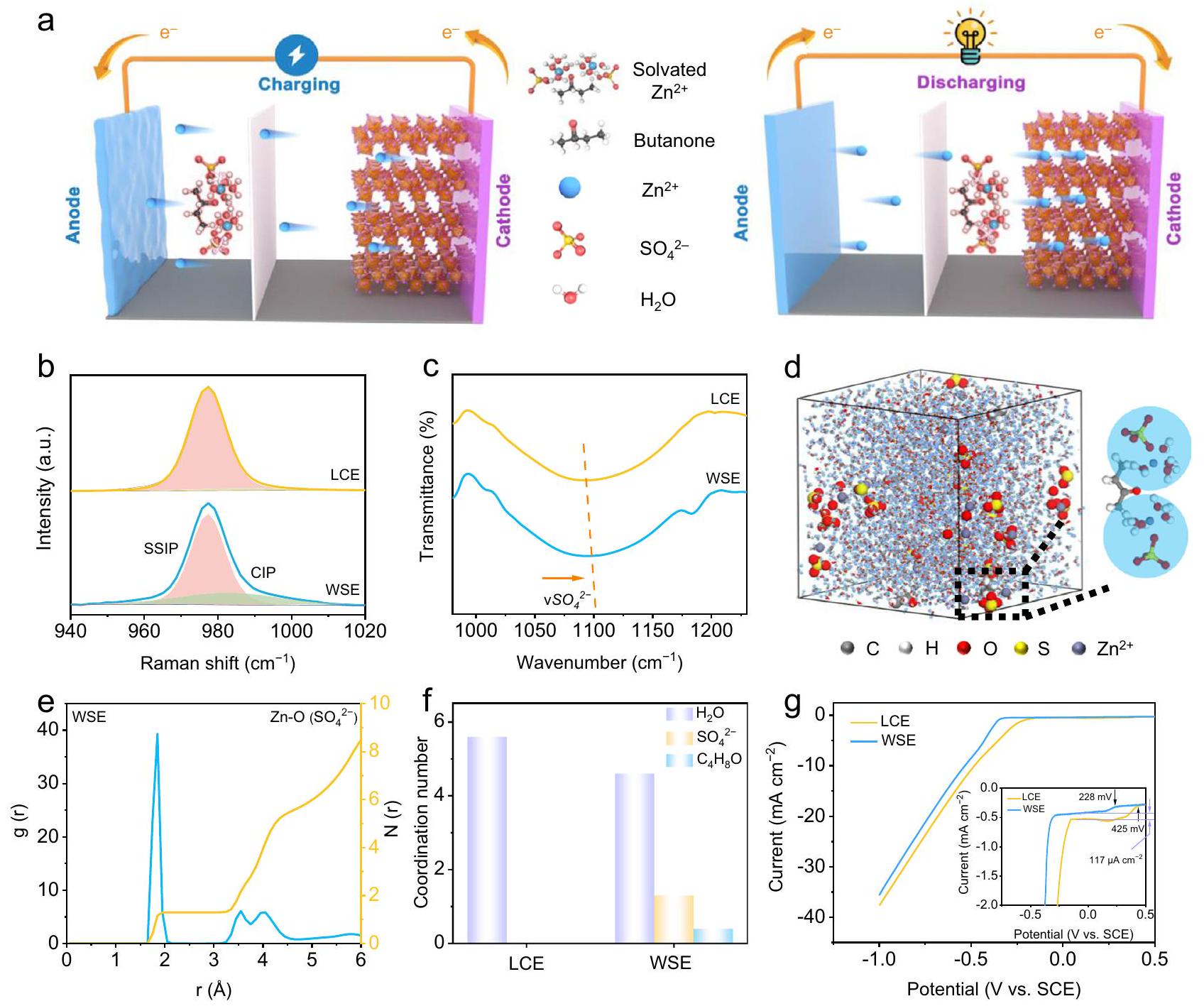
يتكون WSE من الماء، والمذيب المساعد (الإضافي)، وملح الإلكتروليت. نظريًا، يتطلب بناء بيئة ضعيفة الترطيب أن يلبي المذيب المساعد الشروط التالية: (1) قابل للامتزاج مع الماء؛ (2) انخفاض في القطبية (أي، صغير ); و (3) القدرة النووية المنخفضة تجاه أيونات المعادن (أي، DN منخفض). الجدول التكميلي S1 يسرد المذيبات العضوية الشائعة التي تلبي كلا من وقيم DN أقل من الماء. ومع ذلك، فإن الأصغرتشير القيمة إلى أن المذيب أقل قطبية وأكثر صعوبة في الذوبان في الماء القوي القطبية. من خلال تحليل ما إذا كانت المذيبات المختلفة يمكن أن تولد روابط هيدروجينية مع الماء لتقليل الطاقة الحرة لجيبس من نظام، اخترنا البيوتانون كالمذيب المساعد الرئيسي لهذه الدراسة بسبب قابليته الجيدة للذوبان في الماء. للتحقيق في الجرعة المناسبة من البيوتانون، قمنا بتحضير تركيزات مختلفةالإلكتروليتات ) والكهارل المشبعة بالبيوتانون المقابلة لها في التجربة الأولية. من خلال اختبار استقرار الدورة لخلايا Zn/NVO الكاملة مع كهارل مختلفة، تم تحديد صيغة الكهارل المحسّنة. كما هو موضح في الشكل التوضيحي 2، تظهر خلايا Zn/NVO الكاملة أفضل أداء للدورة ( احتفاظ السعة بعد 1000 دورة). لذلك، 0.5 م aqueousحل مع إضافات البيوتانون المشبعيتم اقتراحه لتجميع بطاريات AZIBs عالية الأداء. الإلكتروليت ذو التركيز المنخفض (LCE،بدون إضافات هو الإلكتروليت الأساسي. كما يتضح من طيف رامان في الشكل 1ب، فإن الإشارة التي تتوافق معتتحول الاهتزازات إلى عدد موجي أعلى بعد إضافة البيوتانون (من 977.1 إلىفي WSE). علاوة على ذلك، هناك فرق واضح في نطاقيمكن ملاحظته عند تداخل طيف رامان لـ LCE و WSE (الشكل التكميلي 3). تشير هذه الاتجاهات المتغيرة إلى هيكل الإذابة لـيتحول من زوج أيونات مفصول في المذيب النقي (SSIP) إلى التعايش بين SSIP وزوج الأيونات المتلامسة (CIP). في هذه الأثناء، الـاهتزاز عندكما يشهد تحولًا إيجابيًا ضعيفًا في WSE، مما يدل على وجود روابط هيدروجينية بين الجزيئات قوية بين البيوتانون و (الشكل التوضيحي 4). تغير هيكل الإذابة لـفي WSE تم الشهادة أيضًا على التحول الإيجابي الناتج عن البيوتانونفرقة في مطيافية الأشعة تحت الحمراء بتحويل فورييه (FT-IR) (الشكل 1c).طيف الرنين المغناطيسي النووي (NMR) يؤكد بشكل أكبر تأثير الروابط الهيدروجينية القوية بين البيوتانون و. الـيتحول الإشارة إلى ppm أقل بعد إدخال البيوتانون (الشكل التكميلي 5)، على سبيل المثال من 4.70 إلى 4.68 ppm لـ WSE. وذلك لأن كثافة الإلكترون لمجموعات الهيدروكسيل تزداد بسبب مجموعات الكربونيل المانحة للإلكترونات نتيجة لتكوين الروابط الهيدروجينية (HBs). يتم عرض الموصلية الأيونية لمختلف الإلكتروليتات في الشكل التكميلي 6. يمكننا أن نرى الموصلية الأيونية للماءتنخفض مع إضافة البيوتانون، وهو ما قد يكون ناتجًا عن تقليل حركة الأنيونات بسبب إدخال البيوتانون الذي يظهر تأثير الروابط الهيدروجينية مع. ومع ذلك، فإن وجود العناصر السالبة الكهربيةفي PSS يمكن أن يقلل بشكل كبير من الجهد الكهروستاتيكي لـ، مما يسهل انتشاره. تم حساب معامل الانتشار من طرق الديناميكا الجزيئية (MD) ويدعم هذه النقطة بشكل جيد (الشكل التوضيحي 7). وبناءً عليه،رقم النقل) من WSE يزيد من ~0.34 إلى ~0.44 (الشكل التوضيحي 8). علاوة على ذلك، يتم تقليل نقطة التجمد لـ WSE إلى ، مما يدل على خاصية مقاومة التجمد المحسّنة لـ WSE (الشكل التوضيحي التكميلي 9). قيم الرقم الهيدروجيني لـ LCE و WSE هي 4.28 و 4.02. نظرًا لأن البيوتانون لا يتأين في المحلول المائي، فإن البيوتانون نفسه ليس له تأثير على تغير الرقم الهيدروجيني لـ WSE. ومع ذلك، لا يمكنه الذوبان وإن إدخال البيوتانون يقلل من محتوىمن 40 مل في LCE إلى 35 مل في WSE. لذلك، الـفي WSE ستذوب أكثرالملح مقارنةً بذلك في LCE. بالنظر إلىيتم التحلل المائي في المحلول المائي، أكثرتم حلها بواسطةفي WSE سيؤدي إلى تحلل أكثر شدة وبالتالي فإن درجة الحموضة في WSE أقل قليلاً من تلك في LCE. لزوجة LCE و WSE هي 1.25 و، على التوالي.
تم تطبيق طرق MD بشكل إضافي لمحاكاة الفروق في هيكل الإذابة بين LCE و WSE. كما هو موضح في الشكل 1d والشكل التكميلي 10، فإن PSS لـيتكون فقط منفي LCE بينما جزئي يتم استبداله بـ بعد إدخال البيوتانون. يتم عرض متوسط عدد التنسيق (ACN) ودوال التوزيع الشعاعي (RDFs) للنظامين في الشكل 1e و f والشكل التكميلي 11. من الواضح أنه لا يوجد أي أنيون في PSS منفي أنظمة LCE. بالمقابل، في الأنظمة التي تحتوي على البيوتانونرقم التعريف الضريبيفي نظام PSS يمثل 1.3، مرتبطًا بانخفاض ACN بـمن
الشكل 1 | هيكل الإذابة لـفي LCE و WSE. رسومات تخطيطية لآلية العمل لـ WSE. طيف رامان،طيف FT-IR لـ LCE و WSE. صورة ثلاثية الأبعاد لـ WSE تم الحصول عليها من محاكاة الديناميات الجزيئية وصورة مكبرة جزئيًا تمثلهيكل الحل. e RDFs لـمجمعة من محاكاة الديناميكا الجزيئية في WSE.عدد التنسيق لـمع أنواع مختلفة في LCE و WSE.منحنيات LSV في LCE و WSE عندالجزء المرفق هو منحنيات LSV المكبرة في LCE و WSE. 5.6 إلى 4.3، مما يحقق التكوين الناجح لـ WSE. الاستبدال الجزئي لـبواسطة يجب أن تُنسب الأيونات إلى القدرة المنخفضة على الإذابة للمذيب في WSE. تأثير الثابت العازل على يمكن تصوير تفاعلات المذيب بواسطة القوانين الفيزيائية الكيميائية الكلاسيكية:
أين هو تفاعل -مذيب، هو الثابت العازل، هو شحنة الأيون،هو عزم ثنائي القطب للثنائي القطب، هو المسافة بين الأيون ومركز ثنائي القطب، و هو زاوية ثنائي القطب بالنسبة للخطانضمام الأيون ومركز ثنائي القطب. في WSE، يقلل البيوتانون بشكل كبير منالمذيب ويقلل من التفاعل بينومذيب. كبطاقة دخول إلى PSS منيتنافس عليه المذيبات والأنيونات، مما يقلل من التفاعل بينوالمذيب يعني أن الأنيون يمكنه الدخول إلى PSS لـوبذلك تشكيل CIP. التم اختبار إمكانيات الطلاء والإزالة على القطب الكهربائي من التيتانيوم. كما هو موضح في الشكل 1g، يمكن أن تؤجل WSE جهد البداية لتفاعل الهيدروجين من 425 مللي فولت إلى 228 مللي فولت مقابل SCE. بالإضافة إلى ذلك، يتم القضاء على تيار تفاعل الهيدروجين بواسطةمع ال إضافة البيوتانون، مما يشير إلى أن هيكل الإذابة المتغير يمكن أن يثبط بشكل كبير نشاط تفاعل الهيدروجين في WSE.
قابلية عكس stripping/plating لقطب الزنك في WSE
لتقييم تأثير WSE على دورات الطلاء/الإزالة للأنود Zn،تم تجميع واختبار خلايا متماثلة باستخدام LCE و WSE. تظهر الخلايا التي تستخدم WSE عمر دورة محسّن مقارنة بتلك التي تستخدم LCE عند و (الشكل التوضيحي 12). والأكثر تشجيعًا، يمكن للخلايا التي تستخدم WSE أن توفر الاستقرار لأكثر من 70 ساعة عند كثافة تيار عالية ( ) والسعة ( ) مع نسبة عالية من DOD بينما لا يمكن للخلايا التي تستخدم LCE العمل (الشكل 2أ). إلى أفضل معرفتنا، فإن هذا الأداء يتجاوز بكثير الأنود Zn المتقدم (الجدول التكميلي S2). تم إجراء اختبار الطلاء/الإزالة بشكل إضافي في خلايا Ti/Zn غير المتناظرة بناءً على LCE و WSE. كما هو موضح في الشكل 2ب والشكل التكميلي 13، بعد الكفاءة النسبية المنخفضة في الدورات القليلة الأولى والتي تعود إلى توافق الشبكة، فإنالخلايا التي تعتمد على WSE يمكن أن تقدم كفاءة عالية لـبالإضافة إلى الاستقرار على المدى الطويل ). في المقابل، الـ الخلايا التي تستخدم LCE محاصرة بدورة حياة قصيرة ) و CE المنخفض ( الذي يمكن أن يُعزى إلى نمو الدندريت غير المرغوب فيه وتفاعل الهيدروجين.
الشكل 2 | الأداء الكهروكيميائي لـدراسة الأنود في WSE وآلية الحماية المقابلة. ملفات دورة جلفانية للخلايا المتماثلة مع LCE و WSE فيقياسات الكفاءة الكهروستاتيكية (CE) لخلايا Ti/Zn تحت أنظمة إلكتروليت مختلفة فيصور SEM لرقائق الزنك بعد 50 دورة فيفي LCE و WSE. e XRD
نمط رقائق الزنك بعد 50 دورة فيفي LCE و WSE.مقاومة نقل الشحنة المخططة لواجهة Zn/الإلكتروليت المقاسة من خلية Zn/Zn المتماثلة باستخدام LCE و WSE. رسم تخطيطي لكيفية عمل أنود الزنك في LCE و بورصة وارسو.
آلية حماية WSE لـأنود
يتم مراقبة سبب الاستقرار المعزز لقطب الزنك في WSE من خلال SEM وXRD والقياسات الكهروكيميائية. يقدم SEM الأسطح الخشنة والمسامية لقطب الزنك مع بلورات زنك غير منتظمة في LCE عندبعد 50 دورة (الشكل 2c)، والتي تتدهور مع زيادة كثافات التيار والسعات إلى (الشكل التكميلي 14a). على العكس، يمكن ملاحظة الأسطح المسطحة المكونة من Zn المودع بكثافة في جميع ظروف الاختبار في WSE (الشكل 2d والشكل التكميلي 14b). تم إجراء تحليلات XRD لتقييم التركيب البلوري للودائع Zn بعد 50 دورة طلاء/إزالة.كما هو موضح في الشكل 2e، فإن قمة [002] للترسبات الزنك هي الأقوى في WSE. نسب شدة قمة [002] إلى قمة [101] هي على التوالي 0.44 و 0.99 لـ LCE و WSE، مما يشير إلى زيادة مستويات [002] للترسبات الزنك في WSE. بالنظر إلى شبكة HCP (أي، مجموعة الفضاء: ) من معدن الزنك، يُعتقد أن الزنك المترسب يتجمع عموديًا على محور c، مما يؤدي إلى سطح أملس كما هو ملاحظ من صور SEM عندما يتم تغيير معلمة الدورة إلىنسبة شدة قمة [002] إلى قمة [101] للزنك في WSE تزداد إلى 2.91، مما يشير إلى ترسيب أكثر كثافة للزنك بمعدل مرتفع (الشكل التكميلي 15). بالإضافة إلى ذلك، هناك قمتان بارزتان عند و يمكن العثور عليها لألواح الزنك التي تم تدويرها في LCE، وذلك بسبب تفاعل الهيدروجين وتكوين المنتجات الثانوية فيإلكتروليت. على العكس، لا توجد قمة مميزة لـيمكن العثور على ذلك لقطب الزنك في WSE، مما يشير إلى أن تفاعل الهيدروجين المنخفض (HER) مثبط بشكل كبير. يؤكد زيادة جهد التآكل بشكل أكبر على القدرة المعززة لمقاومة التآكل لـ WSE لحماية أنود الزنك (الشكل التكميلية 16).
التم فهم عملية الترسيب بشكل أفضل من خلال تقنيات التحليل الكهروكيميائي. طاقة التنشيط ( ) لسرعة التجفيف لـ تمت مقارنة أيونات بناءً على معادلة أرهينيوس في إلكتروليتات مختلفة في الشكل 2f.القيم هي 41.4 وفي إلكتروليتات LCE و WSE، على التوالي، مما يشير إلى انخفاض حاجز طاقة إزالة الحلول في WSE، والذي يرجع إلى هيكل الحلول الفريد من نوع الأنيون.في WSE الذي يسهل عملية إزالة الذوبان من خلال تأثير التنافر الكهروستاتيكي مع أنود الزنك الموجب القطبية.بفضل تحسين حركيات إزالة الذوبان لـفي WSE، يتم تعزيز خطوة النواة الإضافية للزنك أيضًا. كما هو موضح في الشكل التوضيحي 18، فإن جهد النواة للقطب الزنك في WSE أقل من ذلك في LCE عبر مجموعة من كثافات التيار. )، وهو مفيد للنمو المت uniform للودائع Zn. لذلك، يمكن أن يُعزى الاستقرار المعزز لقطب الزنك في WSE إلى: (i) بيئة فقيرة بالماء تتشكل بنية الحل في WSE التي تقمع تآكل HER والتفاعلات الجانبية الأخرى؛ (ii) مثل هذه البنية الحل.مفيد للصيامالهجرة و
الشكل 3 | الأداء الكهروكيميائي وتطور الهيكل لقطب NVO في WSE. أ منحنيات GCD عندمقارنة قدرة المعدل ومقارنة استقرار الدراجات عندمن خلايا NVO في LCE و WSE. الصورة المصغرة في الشكل 3c هي الاستقرار الدوري المكبر في لخلايا Zn/NVO في LCE و WSE. منحنيات GCD لـ إلكترود NVO باستخدام WSE فيأنماط XRD خارج الموقع وخريطة الكنتور المقابلة.منحنيات TG وأنماط XRD لقطب NVO بعد 50 دورة فيفي LCE و WSE. معامل الانتشار في حالات التفريغ المختلفة في LCE و WSE وفقًا لقياس GITT.
عملية إزالة الذوبان، التي تساهم بشكل أكبر في التبلور والنمو المتجانس (الشكل 2g).
استقرار قوي لدورات المواد الكاثودية في WSE
لفحص ما إذا كان WSE يؤثر على استدامة دورة الكاثود، تم تجميع خلايا كاملة باستخدام NVO كموضوع للدراسة. يمكن العثور على نتائج التوصيف النموذجية باستخدام المجهر الإلكتروني الماسح (SEM) وحيود الأشعة السينية (XRD) لـ NVO في الشكل التكميلي 19. تظهر منحنيات الفولتمترية الدورية (CV) في الدورات الثلاث الأولى من خلية Zn/NVO مع WSE زوجين من قمم الأكسدة والاختزال المنسوبة إلى و (الشكل التوضيحي 20). لاحظ منحنيات CV عند و الدورات متقاربة تقريبًا، مما يدل على استقرارها الكهروكيميائي الجيد. الشكل 3أ يظهر منحنيات الشحن والتفريغ الجلفاني (GCD) عند خلايا Zn/NVO مع LCE و WSE، على التوالي. تتبع تفوق سعة خلايا Zn/NVO ترتيب WSE و LCE، مما يشير إلى أن إضافة البيوتانون يمكن أن تعزز بشكل كبير قدرة التخزين لـ NVO. كما تم إثبات التأثير الإيجابي لإضافة البيوتانون من خلال مقارنة قدرة المعدل، حيث يظهر خلية Zn/NVO مع WSE أفضل احتفاظ بالسعة.من 0.1 إلى (الشكل 3ب والشكل التكميلي 21). يمكن أن يؤدي وجود البيوتانون أيضًا إلى استقرار خلايا Zn/NVO بشكل فعال أثناء الدورة. في WSE، يحتفظ الجهاز بسعة عالية من بعد 100 دورة عند معدل معتدل منأفضل بكثير من النظائر التي تحتوي على LCE، الشكل التوضيحي الإضافي 22). زيادة كثافة تيار الاختبار إلىيزيد الفجوة في الأداء بين هذين الجهازين. خلية Zn/NVO مع WSE تظهر احتفاظًا بالسعة بنسبة 99.1% بعد 20000 دورة بينما تلك التي مع LCE تفشل بسرعة بعد 400 دورة فقط (الشكل 3c). لتسليط الضوء على فعالية WSE، نقارن استقرار الدورة لخلية Zn/NVO مع أعمال أخرى تم الإبلاغ عنها مؤخرًا تركز على تصميم الإلكتروليت. كما هو موضح في الجدول التكميلي S3، فإن احتفاظ السعة لخلية Zn/NVO باستخدام WSE أعلى من ذلك لـالخلايا المستندة إلى كيمياء إلكتروليت أخرى، مؤكدة فعالية WSE. استفادت خلايا Zn/NVO مع WSE من القدرة المحسنة على مقاومة التجمد، حيث يمكن أن تحافظ على سعةبعد 100 دورة مع احتفاظ بالسعة بـفي (الشكل التوضيحي 23)، بينما يمكن لنظيره أن يعمل بصعوبة. بالإضافة إلى ذلك، فإن استقرار خلايا Zn/NVO في WSE مع كاثود بتحميل كتلة عالية (، يُشار إليه بـ تم التحقيق في NVO). سعة عالية مناحتفاظ بسعة عالية منوقدرة ملحوظة علىبعد 100 دورة عنديمكن تحقيقه لـ، مما يدل على صلاحية WSE في استقرار AZIBs المعتمدة على V ذات السعة العالية (الشكل التوضيحي 24). والأكثر تشجيعًا، نجد أن استخدام WSE يمكن أن يحسن بشكل ملحوظ من قدرة المعدل وثبات الدورة لغيرها من
أنظمة AZIB، على سبيل المثالالخلايا والخلايا (الأشكال التكميلية 25 و26)، مما يثبت عالمية استراتيجية WSE المقترحة. بالإضافة إلى ذلك، فإن استقرار الدورة لـ و تم تقديم الخلايا ذات التحميل الكاثودي العالي في الشكل التوضيحي 27. مقارنةً بالخلايا التي تستخدم LCE، فإن الاحتفاظ المطول بالسعة و يمكن الحصول عليه لـ و الخلايا باستخدام WSE. مخططات راغون لـ و تظهر الخلايا التي تستخدم WSE في الشكل التكميلية 28 (استنادًا إلى تحميل الكتلة لمواد الكاثود)، حيث تكون كثافات الطاقة 269 و 170.5 و 360.2 واط ساعة لكل كيلوجرام.تم الحصول عليها لـ و الخلايا.
آلية الحماية لـ WSE للقطب السالب
للتحقيق في السبب الأساسي للأداء الكهروكيميائي المختلف لخلايا Zn/NVO في إلكتروليتات مختلفة، تم إجراء عدة تحليلات خارجية لمراقبة الهيكل وتغير التكافؤ لقطب NVO خلال عمليات الشحن/التفريغ المتكررة. عرض الشكل 3e و f أنماط XRD الخارجية لـ NVO في WSE في حالات التفريغ التمثيلية (A-D) والشحن (D-G) (الشكل 3d). لاحظ أن الظهور القابل للعكس (التفريغ إلى D) والاختفاء (الشحن إلى G) للقمة عنديمكن تعيينه إلى، مما يشير إلى وجود قابلية للعكسسلوكيات الإدخال/الاستخراج في قطب NVO. زنك تكشف طيفيات XPS عن القابلية العكسية آلية الإدخال/الاستخراج لقطب NVO، حيث تكون شدة قوية منالطيف في الحالة D يشير إلى إدخالبينما يصبح أضعف عند الحالة G (الشكل التكميلي 29). إن التحول الإيجابي لطيف Zn 2p يعود إلى تكوينفي الحالة D، يتوافق بشكل جيد مع نتائج XRD. بالإضافة إلى ذلك، فإن المستوى (001) ينتقل تدريجياً منإلىفي الحالة D ثم يعود إلى زاوية 2 ثيتا الأولية عند الحالة G، مما يشير إلى انخفاض المسافة d لسطح (001) في الحالة D. وعلى العكس، يمكن ملاحظة الانزياح السلبي لسطح (110) في الحالة D، مما يدل على زيادة المسافة d لسطح (110) (الشكل 3f). هذه الظاهرة ناتجة عن قطبية المادة المدخلة.وأيوناتهم المائية التي تسبب تشوه الهيكل. لتسليط الضوء على الفرق بين NVO المدورة في LCE و WSE، قمنا بتفكيك خلايا Zn/NVO مع LCE و WSE بعد 50 دورة عند كثافة تيار منخفضة منقمنا بتحديد جهد القطع لـ NVO مع كلا الإلكتروليتين عند 1.6 فولت (حالة الشحن الكامل) للتحقيق في الشبكة المدخلة.إلى NVO في إلكتروليتات مختلفة. تم إجراء عدة تحليلات بما في ذلك التحليل الحراري الوزني (TG) ، و XPS ، و XRD ، و SEM لتقييم تطور هيكل أقطاب NVO المختلفة. في منحنيات TG ، فقدان الوزن فوقيمكن أن يُعزى ذلك إلى فقدان الشبكةالشكل 3 ج يشير إلى أن NVO الذي تم تدويره في WSE يظهر فقدانًا أقل في الشبكة.، مشيرًا إلى كمية الإدخال المشتركتم تقليله إلى حد ما.تؤكد طيفيات XPS بشكل أكبر على الانخفاضمن NVO مع WSE، حيث تمثل شدة الذروة عند 532.5 إلكترون فولت من NVO مع WSE أقل من ذلك مع LCE (الشكل التكميلي 30). كما هو موضح في الشكل 3h، فإن XRD لـ NVO الذي تم تدويره في LCE يشهد توسعًا شبكيًا أكثر وضوحًا من ذلك في WSE.إلى )، كما يتضح من مستوى (001) الأكثر انحرافًا عن NVO النقي، مما يشير إلى التغيرات التخفيفية في الشبكة البلورية لـ NVO في WSE. قد يتسبب هذا التمدد في الشبكة البلورية لـ NVO في LCE في إجهاد وتكوين الشقوق الناتجة، كما يتضح من صور SEM (الشكل التكميلي 31). تم تشكيل المزيد من الشقوق على قطب NVO الذي تم تدويره في LCE بينما لوحظت سطح مستوٍ لقطب NVO الذي تم تدويره في WSE، مما يشير إلى القدرة الوقائية لـ WSE لـ NVO على مستوى القطب. استنادًا إلى النتائج التجريبية المذكورة أعلاه، يمكن الاستنتاج أن يحدث الإدخال المشترك في كل من LCE و WSE، باستثناء المزيد منيتم إدخاله بشكل مشترك في NVO في LCE خلال عملية الدورة. علاوة على ذلك، فإن إدخال كمية مناسبة منيفيد في عملية تخزين الطاقة لـ NVO بينما الإدخال الزائد لـيمكن أن يسبب تلاشي السعة. بالإضافة إلى تشوه الهيكل، يجب أيضًا الانتباه إلى ذوبان الكاثود لتدهور سعة NVO. تم غمر أقطاب NVO أولاً في LCE و WSE لمدة 7 أيام لاختبار قابليتها للذوبان. كما هو موضح في الملحق
الشكل 32، الزجاجة التي تحتوي على WSE تظهر لونًا أصفر أفتح مقارنةً بـ LCE، مما يشير إلى أن ذوبان NVO قد انخفض بسبب البيوتانون. قمنا أيضًا بإجراء اختبار الذوبان في خلايا العملة من نوع 2032، حيثتم استخدام الإلكتروليتات. بعد الراحة لمدة 7 أيام، تم إخراج الفواصل من الخلايا التي تحتوي على LCE و WSE واستخدامها لاحقًا لاختبار البلازما المقترنة بالحث (ICP). كما هو موضح في الشكل التكميلي 33، فإن نسبة ذرات عنصر الفاناديوم لـ LCE و WSE هي و ، مما يشير إلى أن WSE يمكن أن يثبط بشكل كبير ذوبان NVO تحت ظروف العمل الفعلية. تظهر أنماط XRD لـ NVO المنقوعة في LCE و WSE لمدة 7 أيام في الشكل التوضيحي 34. لا تظهر المستويات (001) و (110) لـ NVO المنقوعة في كل من LCE و WSE أي انحراف عن NVO الأصلي باستثناء أن المستوى (001) لـ NVO المنقوعة في LCE مفقود، مما يشير إلى أن هيكل NVO قد دُمّر في LCE بسبب مشكلة الذوبان. لتسليط الضوء على التأثير السلبي لذوبان الكاثود على الأداء العام لـ Zn/ZVO، تم اختبار أقطاب NVO التي خضعت لاختبارات الذوبان (الراحة تم إخضاع خلايا NVO مع LCE و WSE لمدة 7 أيام لاختبارات GCD. بالمقارنة مع الخلايا التي لم تتعرض لاختبار الذوبان (الشكل 3a)، تظهر أقطاب NVO التي تم اختبارها في LCE و WSE فقدانًا في السعة بنسبة 44.4% و 7.8% في الدورة الأولى، على التوالي، مما يشير إلى أن WSE يمكن أن يثبط أيضًا ذوبان الكاثود لـ NVO (الشكل التكميلي 35).
تم تحفيز حركيات التفاعل لـ NVO في إلكتروليتات مختلفة بواسطة تقنية الطيف الكهربائيimpedance (EIS)، والتفريغ الجلفاني المتقطع (CV) وتقنية الت titration الجلفاني المتقطع (GITT). تُظهر طيف EIS لخلية Zn/NVO الكاملة مع LCE و WSE بعد التنشيط في الشكل التوضيحي 36. تُظهر خلية Zn/NVO الكاملة مع WSE مقاومة واربورغ أصغر. ) من ذلك في LCE، مما يشير إلى عملية نقل الأيونات الميسرة لـ تخزين الأيونات بسبب تغير هيكل الإذابةمنحنيات السيرة الذاتية لـتم اختبار خلايا NVO بمعدلات مسح مختلفة (القيم b لـ NVO في WSE هي 0.576 و0.609 و0.636 و0.624، مما يعني أن عملية تخزين الشحنة يتم التحكم فيها بشكل متزامن من خلال مزيج من انتشار الأيونات وسلوكيات السعة. لاحظ كلا منقيم ومساهمة السعة عند جميع معدلات المسح لخلايا Zn/NVO باستخدام WSE أعلى من تلك في النقاء.الإلكتروليتات، مما يشير إلى سرعة تفاعل كينتيك NVO في WSE. تم إجراء قياس GITT لتقييم معامل انتشار الأيونات ( ) في كاثود NVO (الشكل 3i والشكل التكميلي 38). معامل انتشار الأيونات ( ) عند انخفاض DOD يعكس ديناميكية الإدخال أثناء عند نسبة عالية من DOD تمثل ديناميكية الإدخال.منالإدخال مشابه في LCE و WSE، مما يشير إلى أن إدخال البيوتانون له تأثير ضئيل علىديناميكية الإدخال. ومع ذلك، فإنمنالإدخال في WSE أعلى من ذلك في LCE، مما يشير إلى السرعة الأكبرديناميكية الإدخال مع البوتانون الذي تم استقدامه حديثًا في WSE. هذه الظاهرة تحدث لأن (i) WSE يظهر زيادة فيديناميكا إزالة الذوبان؛ (ii) الجرعة الزائدة المضافة المشتركةيتم تقليله في WSE. الإدخال الزائد لـفي LCE يمكن أن يمنع الـمسار الإدخال، مما يزيد من مقاومة الإدخال. على العكس، هيكل الإذابة المتحول لـمع إضافة البيوتانون يمكن أن تسهل عملية إزالة الذوبان وتقليل كمية الإدخال المشترك . لذلك، يمكن استنتاج آلية الحماية لـ WSE لـ NVO على النحو التالي: (i) الإدخال المفرط المشترك لـيتم كبحه ويتم تخفيف تشوه/انهيار الهيكل لـ NVO أثناء الدورة؛ (ii) يتم تقليل ذوبان NVO بشكل كبير لأن نشاطيقل بسبب التفاعل القوي لروابط الهيدروجين بينوبوتانون.
تصنيع خلية Zn/NVO من النوع AA تعتمد على WSE
تُستخدم بطاريات AA في مجموعة واسعة من السيناريوهات في الحياة اليومية، والتي تتطلب أنظمة بطارية ذات أمان عالٍ وأداء واستدامة. لذلك، لاختبار جدوى WSE للتطبيق العملي، تم تجميع خلايا AA من نوع Zn/NVO القابلة لإعادة الشحن (المشار إليها بـ AA-Zn/NVO) بناءً على WSE (الشكل 4a). تم تحقيق هذا النموذج الخلوي من خلال لفّإلكترود NVO، فاصل ورق بني ورقائق Zn لتثبيتها وملئها في الفولاذ المقاوم للصدأ
الشكل 4 | الأداء الكهروكيميائي لخلايا AA-Zn/NVO. أ رسم تخطيطي لخلايا AA-Zn/NVO.منحنيات GCD عنداستقرار الدراجات عند 0.66 C من AAالخلايا والمنحنيات المختارة لـ GCD للدورات الأولى والخامسة عشرة والثلاثين عند 0.66 C. الصور الرقمية لسيارة التحكم عن بعد المدعومة بخلايا AA-Zn/NVO. الإضافات
في الشكل 4 ب و هـ هي الصور البصرية للمنتج كما تم تصنيعه خلايا. مقارنة بين AZIBs المعتمدة على WSE وAZIBs الأخرى المبلغ عنها بناءً على كيمياء إلكتروليت مختلفة. أسطوانة (الشكل التوضيحي 39). يختلف عن معظم الدراسات المبلغ عنها التي تعتمد على خلايا العملة على نطاق المختبر مع نسب N/P و E/C عالية، حيث يتم تحقيق نسب N/P و E/C أقل بكثير في هذه الخلية من النوع AA (الجدول التوضيحي S4). لتجنب التحلل المحتمل للإلكتروليت، يتم تحديد نطاق الجهد لـيتم ضغطه إلىقدرة مرضية منتم الحصول على ذلك عند معدل C قدره 0.66، وهو قريب من السعة النظرية لقطب NVO، ويمكن مقارنته حتى ببعض بطاريات الزنك والمنغنيز الجافة التجارية (الشكل 4ب). والأهم من ذلك، أن منحنيات GCD المختارة لـ AAZn/NVO في الدورة الأولى والخامسة عشرة والثلاثين لا تظهر أي فقدان واضح في السعة أو تذبذب في الجهد، مما يثبت أنها يمكن أن تدعم دورة طويلة مستقرة للغاية بالإضافة إلى كفاءة عالية (الشكل 4ج و د). تم إخراج أقطاب NVO و Zn للجهاز بعد تقييم الدورة لإجراء مزيد من التحليل باستخدام SEM. تظهر صور SEM لقطب NVO بعد الدورة عدم وجود تغيير كبير بينما يظهر ورق الزنك سطحًا أملسًا (الشكل التكميلي 40). تدعم جميع المزايا المذكورة أعلاه اقتراحنا بأن WSE المقترح يمكن أن يثبت كل من قطب NVO وقطب Zn، حتى في نظام خلية قابل لإعادة الشحن من نوع AA عملي. كدليل على المفهوم، يمكن أن يوفر AA-Zn/NVO المتكامل مع WSE طاقة كافية لتشغيل سيارة تحكم عن بعد (الشكل 4هـ والفيلم التكميلي 1). عند أخذ جميع العوامل بما في ذلك السعة، وقدرة المعدل، وعمر الدورة، والتكلفة في الاعتبار، من المعقول أن نتوقع أن مثل هذا WSE يمكن أن يتفوق على أكثر بطاريات AZIBs تقدمًا المصممة عبر كيمياء إلكتروليت مختلفة (الشكل 4و).
نقاش
باختصار، قمنا بتطوير WSE واعد لبطاريات AZIBs المستدامة للغاية من خلال تثبيت الكاثود وأنود الزنك في الوقت نفسه. تم تحقيق ذلك باستخدام البيوتانون كعامل مضاد للمذيب لتقليل قوة الذوبان لـوبالتالي تقليل المذابلتشكيل بنية حل مائية فقيرةلتخفيف تشوه الهيكل/انهيار الكاثود أثناء الدورة بالإضافة إلى نمو الدندريت والتفاعلات الجانبية على الأنود الزنك. كدليل على الفكرة، تم تحقيق استقرار ممتاز للأنود الزنك في ظروف الاختبار. و يتم تحقيق (DOD). علاوة على ذلك، ثلاثة نماذج نموذجية من AZIBs بما في ذلك، و تم تجميع AZIBs باستخدام WSE وعرضت استقرارًا ممتازًا في الدورة. يتم إثبات فعالية WSE لـ AZIBs بشكل أكبر في AA-Zn/NVO، حيث تم تحقيق سعة عالية تبلغ 101.7 مللي أمبير وسعة استقرار عالية تبلغ 96.1% بعد 30 دورة. على الرغم من أنه لا يزال هناك الكثير لاستكشافه، مثل البحث عن كاثودات ذات أداء أفضل وتقنية التصنيع لكاثودات ذات تحميل كتلي أعلى.تأخذ هذه الاستراتيجية لتصميم الإلكتروليت الخطوة الأولى نحو تحقيق الاستدامة العالية لبطاريات الزنك-هواء.
طرق
تحضير الإلكتروليت
تم تحضير LCE عن طريق إذابة 5.75 جرام منإلى 40 مل من الماء المقطر لتكوين محاليل شفافة. لتحضير WSE، 5.75 جرام منيتم إضافته إلى محلول مختلط يحتوي على 5 مل من البيوتانون و 35 مل من الماء المقطر حتى تصبح المحاليل شفافة. تركيز في WSE هو 0.5 م.
تحضير الكاثود
تم تحضيره بإضافة 2 جرام من المنتج التجاريفي محلول مائي من NaCl بتركيز 2 م (30 مل) تحت التحريك لمدة 4 أيام عندتم غسل المنتج الأحمر الداكن بالماء المنزوع الأيونات (DI) عدة مرات وتم الحصول عليه بعد التجفيف بالتجميد لـتم تحضيره عن طريق إذابة و 0.7 جرام من دوديكانول سلفات الصوديوم (SDS) في 20 مل من الماء المنزوع الأيونات لتكوين المحلول A. ثم، 20 مل يتم إضافة محلول مائي ببطء إلى المحلول A. بعد التقدم في العمر عند درجة حرارة الغرفة لمدة 24 ساعة، يتم غسل المنتجات عدة مرات بماء منزوع الأيونات. يتم الحصول على العينات أخيرًا بعد التجفيف بالتجميد لـ (MA-EN-CA-1U015Y) تم شراؤه من شركة Canrd Technology Co. Ltd. واستخدم دون أي معالجة. كمثال على ذلك، تم خلط NVO مع الكربون الأسود ومواد الربط من بولي (فلوريد الفينيليدين) بنسبة وزن 8:1:1 في 1-ميثيل-2-بيروليدينون (NMP). تم لصق المعجون على ورق التيتانيوم (بسمك 0.3 مم)، وتم تجفيفه طوال الليل في كانت الكتلة الإجمالية المحملة للقطب الكهربائي.
تصنيع بطارية من نوع AA
تم تحضير الكاثود NVO بنفس الروتين الذي وصفناه في القسم أعلاه. كانت الكتلة الإجمالية المحملة للقطب الكهربائي هيتم اختيار رقائق الزنك بسمك 0.3 مم كأنود، وتم استخدام ورق بني كفاصل. تم لف الكاثود والفاصل والأنود بشكل محكم جدًا وملؤه في أسطوانة من الفولاذ المقاوم للصدأ. تم ربط أطراف كاثود NVO وأنود الزنك بواسطة فيلم الأطراف (MTI) عبر الضغط الحراري. تم إغلاق أسطوانة الفولاذ المقاوم للصدأ بعد حقن 2.0 جرام من WSE. تم إجراء عملية الإغلاق بواسطة آلة الإغلاق بالفراغ الأوتوماتيكية (شركة ووهان جيرويزي للطاقة الجديدة المحدودة). تم ترك البطارية من نوع AA الناتجة للراحة لمدة ساعة قبل الاختبار الكهروكيميائي.
توصيف المواد
تم استخدام مطيافية رامان (Renishaw inVia) ومطيافية الأشعة تحت الحمراء بتحويل فورييه (Vertex70Hyperion3000) والرنين المغناطيسي النووي (Varian INOVA500NB) لدراسة هياكل الإذابة لـتم اختبار المسح الحراري التفاضلي والتوصيلية الأيونية لمختلف الإلكتروليتات بواسطة DSC-204 F1 وLeici DDS-11A. تم إجراء SEM بتقنية الانبعاث الميداني (JSM-6330F) وXRD (D-MAX 2200 VPC، RIGAKU) وTG (TG209F1 Libra R) وXPS (NEXSA، Thermo FS) لدراسة البنى الدقيقة والتركيبات للأنود من الزنك والكاثود من NVO.
القياسات الكهروكيميائية
تم إجراء قياسات السيرة الذاتية (CV) وقياسات التوصيل الكهربائي (GCD) وقياسات الزمن المستمر (GITT) وقياسات الطيف الكهربائي (EIS) على جهاز العمل الكهربائي CHI 760E ونظام البطارية Neware (CT-3008-5V).، شنتشن، الصين). للتدوير الجلفانيتم تجميع خلايا متجانسة من نوع 2032 باستخدام رقائق الزنك (N-buliv Co., Ltd.، بسمك 1 مم) ككاثود وأنود، وألياف زجاجية (Whatman GF/D) كفاصل. لاختبار الطلاء/إزالة الطلاء من الزنك، تم استخدام رقاقة الزنك كقطب مضاد، وتم استخدام لوحة التيتانيوم (بسمك 1 مم) كقطب عمل. تم ضبط جهد القطع لإزالة الطلاء عند 0.5 فولت (مقابل. ) لكل دورة. التوصيفات الكهروكيميائية لـ نيو و تم إجراء التجارب في خلايا من نوع 2032 أو خلايا من نوع AA مع إلكتروليتات مختلفة. نطاق الجهد لـ و خلايا العملة هي، ، و ، على التوالي. بالنسبة لقياس EIS، فإن التردد المطبق يتراوح بين و . في دراسة GITT، تم تفريغ خلية عند معدل لمدة 30 ثانية، تليها خطوة دائرة مفتوحة لمدة 10 دقائق للسماح بالاسترخاء والعودة إلى التوازن. تم الاستمرار في الإجراء حتى وصل جهد التفريغ إلى 0.2 فولت. تم إجراء جميع الاختبارات الكهروكيميائية في غرفة بيئية عند درجة حرارة ثابتة منكثافة الطاقة (E) وكثافة القدرة (P) لـنيو و تم حساب خلايا العملة من منحنيات GCD وفقًا للمعادلتين (2) و (3) على التوالي، حيث I هو تيار التفريغ، وU هو الجهد، وt هو وقت التفريغ.
الحسابات النظرية
تم إجراء محاكاة الديناميات الجزيئية باستخدام مجال القوة (FFMD) باستخدام برنامج MD Material Studio. تم الحصول على معلمات مجال القوة من المجالات العالمية. حجم الصندوق هو، وتم تعيين شروط الحدود الدورية في كلا الاتجاهين. احتوت خلايا المحاكاة على و (LCE) و و 4 بيوتانون (WSE) على التوالي. تم تطبيق طرق إيوالد لحساب التفاعلات الكهروستاتيكية. بالنسبة لحساب التفاعلات الكهروستاتيكية/غير الكهروستاتيكية في الفضاء الحقيقي، تم تعيين طول القطع عند 0.6 نانومتر ووقت التكامل كانت خطوة الزمن 1 فيمتوثانية. تم تسخين النظام من 200 إلى 500 كلفن على مدى 0.5 نانوثانية ثم تم تشغيله لمدة 2.0 نانوثانية للوصول إلى التوازن. تم إجراء محاكاة درجات الحرارة باستخدام طريقة نوز. بالنسبة لتحليل ما بعد المعالجة، تم إجراء محاكاة إنتاجية لمدة 5 نانوثانية.
توفر البيانات
جميع البيانات التي تدعم نتائج هذه الدراسة متاحة ضمن الورقة والمعلومات التكميلية. جميع المعلومات الإضافية متاحة من المؤلفين المراسلين عند الطلب. يتم توفير بيانات المصدر مع هذه الورقة.
References
Li, C., Jin, S., Archer, L. A. & Nazar, L. F. Toward practical aqueous zinc-ion batteries for electrochemical energy storage. Joule 6, 1733-1738 (2022).
Yang, C. et al. All-temperature zinc batteries with high-entropy aqueous electrolyte. Nat. Sustain. 6, 325-335 (2023).
Zhang, Q. et al. Designing anion-type water-free solvation structure for robust Zn metal anode. Angew. Chem. Int. Ed. 133, 23545-23552 (2021).
Zhao, R. et al. Lanthanum nitrate as aqueous electrolyte additive for favourable zinc metal electrodeposition. Nat. Commun. 13, 3252 (2022).
Zheng, J. et al. Reversible epitaxial electrodeposition of metals in battery anodes. Science 366, 645-648 (2019).
Shi, X. et al. Compacting electric double layer enables carbon electrode with ultrahigh Zn ion storage capability. Angew. Chem. Int. Ed. 61, e202214773 (2022).
Zhu, Z. et al. Rechargeable batteries for grid scale energy storage. Chem. Rev. 122, 16610-16751 (2022).
Han, D. et al. A non-flammable hydrous organic electrolyte for sustainable zinc batteries. Nat. Sustain. 5, 205-213 (2022).
Wan, F. et al. Aqueous rechargeable zinc/sodium vanadate batteries with enhanced performance from simultaneous insertion of dual carriers. Nat. Commun. 9, 1656 (2018).
Zeng, Y. et al. Construction of Co-Mn Prussian blue analog hollow spheres for efficient aqueous Zn -ion batteries. Angew. Chem. Int. Ed. 60, 22189-22194 (2021).
Chao, D. et al. Atomic engineering catalyzed electrolysis kinetics for a hybrid aqueous battery with high power and energy density. Adv. Mater. 32, 2001894 (2020).
Zhu, Y., Cui, Y. & Alshareef, H. N. An anode-free battery. Nano Lett. 21, 1446-1453 (2021).
Wang, C. et al. Toward flexible zinc-ion hybrid capacitors with superhigh energy density and ultralong cycling life: The pivotal role of salt-based electrolytes. Angew. Chem. Int. Ed. 60, 990-997 (2021).
Kim, Y. et al. Corrosion as the origin of limited lifetime of vanadium oxide-based aqueous zinc ion batteries. Nat. Commun. 13, 2371 (2022).
Yang, K. et al. Triple-functional polyoxovanadate cluster in regulating cathode, anode, and electrolyte for tough aqueous zinc-ion battery. Adv. Energy Mater. 12, 2202671 (2022).
Liu, C., Xie, X., Lu, B., Zhou, J. & Liang, S. Electrolyte strategies toward better zinc-ion batteries. ACS Energy Lett. 6, 1015-1033 (2021).
Jiang, H. et al. Chloride electrolyte enabled practical zinc metal battery with a near-unity Coulombic efficiency. Nat. Sustain. (2023) https://doi.org/10.1038/s41893-023-01092-x.
Huang, C. et al. Stabilizing zinc anodes by regulating the electrical double layer with saccharin anions. Adv. Mater. 33, e2100445 (2021).
Chen, Y. et al. A Multifunctional anti-proton electrolyte for high-rate and super-stable aqueous Zn -vanadium oxide battery. Nano-Micro Lett. 14, 154 (2022).
Yang, F. et al. Understanding evolution electrochemistry to minimize solvated water impact on Zinc-anode performance. Adv. Mater. 34, 2206754 (2022).
Wang, F. et al. Highly reversible zinc metal anode for aqueous batteries. Nat. Mater. 17, 543-549 (2018).
Cao, L. et al. Solvation structure design for aqueous Zn metal batteries. J. Am. Chem. Soc. 142, 21404-21409 (2020).
Liu, S. et al. Tuning the electrolyte solvation structure to suppress cathode dissolution, water reactivity, and Zn dendrite growth in zinc-ion batteries. Adv. Funct. Mater. 31, 2104281 (2021).
Qin, R. et al. Tuning coordination environment to suppress dendrite formation for high-performance Zn -ion batteries. Nano Energy 80, 105478 (2021).
Qiu, H. et al. Zinc anode-compatible in-situ solid electrolyte interphase via cation solvation modulation. Nat. Commun. 10, 5374 (2019).
Yao, Y. et al. Regulating interfacial chemistry in lithium-ion batteries by a weakly solvating electrolyte. Angew. Chem. Int. Ed. 60, 4090-4097 (2021).
Yang, Y. et al. Weakly solvating effect spawning reliable interfacial chemistry for aqueous Zn/Na hybrid batteries. Adv. Energy Mater. 13, 2203729 (2023).
Yang, H. et al. A Metal-organic framework as a multifunctional ionic sieve membrane for long-life aqueous zinc-iodide batteries. Adv. Mater. 32, e2004240 (2020).
Zhou, M. et al. Surface-preferred crystal plane for a stable and reversible zinc anode. Adv. Mater. 33, e2100187 (2021).
Hao, J. et al. An in-depth study of Zn metal surface chemistry for advanced aqueous Zn-ion batteries. Adv. Mater. 32, 2003021 (2020).
Ma, T. et al. Optimize lithium deposition at low temperature by weakly solvating power solvent. Angew. Chem. Int. Ed. 134, e202207927 (2022).
Liang, W. et al. cathode stabilized by in situ phase transformation for aqueous zinc-ion batteries with ultra-long cyclability. Angew. Chem. Int. Ed. 134, e202207779 (2022).
Huang, J. et al. In situ induced coordination between a “desiccant” interphase and oxygen-deficient navajoite towards highly efficient zinc ion storage. Adv. Energy Mater. 12, 2201434 (2022).
شكر وتقدير
تم دعم هذا العمل ماليًا من قبل مؤسسة قوانغدونغ للبحث الأساسي والبحث التطبيقي الأساسي (2022A1515140008)، ومشروع الابتكار والقوة في المدارس بمقاطعة قوانغدونغ (2020ZDZX2004).
مساهمات المؤلفين
خطط X.L. وصمم المشروع. قام Z.Y. وX.S وJ.W. بتصنيع المواد وأجروا التجارب الكهروكيميائية. قام J.X. بتحليل البيانات. كتب X.L. وX.S وZ.Y. وS.X. المخطوطة. ناقش جميع المؤلفين النتائج وعلقوا على المخطوطة.
وزارة التعليم في مختبر الكيمياء الحيوية غير العضوية والكيمياء الاصطناعية، المختبر الرئيسي للكيمياء منخفضة الكربون وحفظ الطاقة في مقاطعة قوانغدونغ، كلية الكيمياء، كلية الهندسة الكيميائية والتكنولوجيا، جامعة صن يات سن، قوانغتشو، جمهورية الصين الشعبية. كلية البيئة والهندسة المدنية، مركز غوانغدونغ للهندسة والتكنولوجيا لأبحاث المواد النانوية المتقدمة، جامعة دونغقوان للتكنولوجيا، دونغقوان، جمهورية الصين الشعبية. البريد الإلكتروني: xieshil@dgut.edu.cn; yangzj3@mail.sysu.edu.cn; luxh6@mail.sysu.edu.cn
A weakly solvating electrolyte towards practical rechargeable aqueous zinc-ion batteries
Received: 20 April 2023
Accepted: 22 December 2023
Published online: 05 January 2024
(A) Check for updates
Xin Shi , Jinhao Xie , Jin Wang , Shilei Xie , Zujin Yang & Xihong Lu
Abstract
Structure deterioration and side reaction, which originated from the solvated , are the main constraints for the practical deployment of both cathode and anode in aqueous Zn -ion batteries. Here we formulate a weakly solvating electrolyte to reduce the solvating power of and strengthen the coordination competitiveness of to over . Experiment results and theoretical simulations demonstrate that the water-poor solvation structure of is achieved, which can (i) substantially eliminate solvated- -mediated undesirable side reactions on the Zn anode. (ii) boost the desolvation kinetics of and suppress Zn dendrite growth as well as structure aberration of the cathode. Remarkably, the synergy of these two factors enables long-life full cells including and cells. More importantly, practical rechargeable AA-type Zn/NVO cells are assembled, which present a capacity of 101.7 mAh and stability of capacity retention after 30 cycles at 0.66 C .
Rechargeable aqueous Zn -ion batteries (AZIBs) are promising electrochemical devices for stationary energy storage that have been widely investigated by both academia and industry because of the intrinsic merits of Zn anode such as high capacity ( ), low redox potential ( -0.762 V vs. the standard hydrogen electrode (SHE)) and relatively low cost . When coupling the Zn anode with an appropriate cathode (Mn-based, V-based, Prussian blue analogsbased, etc.) and electrolyte ( , etc.), AZIBs can achieve satisfying energy and power density comparable or even superior to commercial aqueous devices like Ni-Zn batteries and lead-acid batteries . In the last decade, substantial progress have been made in the development of high-performance AZIBs. Nevertheless, the limited cycling durability, initiated by dendrite growth and side reactions of Zn anode and structure degradation of the cathode during repeated charge/discharge courses, remains the major obstacle that plagues their practical deployment . The electrode failure of AZIBs is highly dependent on the interfacial structures between electrode and electrolyte, also known as the electric double layer (EDL) . On the
basis of the Bockris-Devanathan-Müller model (Supplementary Fig. 1), the key issues faced by Zn anode and cathode materials can be well explained: (i) Zn dendrite growth is caused by the uneven flux from outer Helmholtz layer to Zn anode, which is associated with the strong coordination bond between and solvated in that leads to sluggish desolvation kinetics of . Such poor desolvation kinetics can also cause the co-insertion of complex into the cathode host, leading to irreversible lattice expansion and ultimately structure degradation . (ii) During the desolvation process of , a large number of active molecules are released and in contact with Zn anode, which in turn triggers hydrogen evolution reaction (HER), corrosion and other side reactions . Therefore, decreasing the number of solvated is the key to inhibiting the failure of both cathode and anode in AZIBs.
To date, some electrolyte modification strategies such as adding high-concentration electrolyte salts and introducing high donor number (DN) organic additives have been proposed to minimize the solvated . Concretely, LiTFSI highly
concentrated electrolyte (HCE) was proposed to suppress the content of solvated and enable a cell with extended life beyond 200 cycles . Despite the inspiring achievements, the viscosity of HCE is too thick, resulting in uneven diffusion of and poor rate capability of full cells. Alternatively, the solvated can be partially replaced by introducing organic molecules with DN greater than such as dimethyl sulfoxide , triethyl phosphate (TEP) , ethylene glycol (EG) , polyethylene glycol , acetamide . For example, it is reported that the addition of to could extend the cycling durability of cells to more than 500 cycles at , seeing a nearly 20 -time lifespan enhancement in contrast to bare . A similar life-extending effect was also observed by using triethyl phosphate (TEP) as the additive . However, these organic additives are used to replace the solvated due to their stronger interaction with , and such interaction will further slowdown the desolvation kinetics of , which is not conducive to the even diffusion of and may even aggravate the growth of Zn dendrites as well as structure fading of cathode materials at high current densities. Therefore, strategic minimization of solvated to simultaneously stabilize anode and cathode of AZIBs still remains challenging.
A more basic way to reduce the number of solvated is by weakening the intrinsic solvating ability of . The main factors that evaluate the solvating ability of the solvent are the dielectric constant and describes the electrostatic force between the solvated ions and DN influences the nucleophilic behavior of solvent . Considering with large (80.4) and DN (18) is the predominant solvent in AZIBs and exhibits a high solvating ability for zinc salts, it is hypothesized the solvating power of can be limited by additives with low and DN. Herein, we formulate a weakly solvating electrolyte (WSE) by introducing low and DN butanone as an additive to 0.5 M to build long-life AZIBs. Experiments and theoretical simulation indicate that WSE can (i) reduce the number of solvated and inhibit side reactions on Zn anode. (ii) boost the desolvation kinetics of and suppress dendrite growth as well as structure fading of cathode materials. Since and anions are competing to enter the solvation sheath of , reducing the number of solvated can enable more anions to enter the solvation sheath of , forming a water-poor solvation structure of . During the deposition process on Zn anode or the insertion process on cathode, the negatively charged electrode surface has electrostatic repulsion with the anion in the solvation sheath of , which helps to accelerate the desolvation kinetics of and promote the uniform diffusion of (Fig. 1a). Consequently, Zn anode cycling in WSE exhibits outstanding stability at an incredibly high current density, areal capacity and depth of discharge , and ). Three representative AZIBs including (NVO), , and cells using WSE were assembled and show excellent cycling stability. More encouragingly, rechargeable AA type Zn/NVO AZIBs were fabricated, which can deliver a high capacity of 101.7 mAh and outstanding stability of capacity retention after 30 cycles at 0.66 C .
Results
Solvation structure of in WSE
WSE consists of water, co-solvent (additive), and electrolyte salt. Theoretically, the construction of a weakly solvated environment requires the co-solvent to meet the following conditions: (1) miscible with water; (2) low polarity (i.e., small ); and (3) low nucleophilic ability to metal ions (i.e., low DN). Supplementary Table S1 lists common organic solvents that meet both and DN values less than water. However, the smaller value indicates that the solvent is more non-polarized and difficult to dissolve in strong polarized water. By analyzing whether different solvents can generate hydrogen bonds with water to reduce the Gibbs free energy of the
system, we selected butanone as the main co-solvent for this study due to its good solubility in water. To investigate the suitable dosage of butanone, we prepared different concentrated electrolytes ( ) and their corresponding butanone-saturated electrolytes in the preliminary experiment. By testing the cycling stability of Zn/NVO full cells with different electrolytes, the optimized electrolyte formula was determined. As shown in Supplementary Fig. 2, Zn/NVO full cell shows the best cycling performance ( capacity retention after 1000 cycles). Therefore, 0.5 M aqueous solution with saturated butanone additives ( v) is proposed for high-performance AZIBs assembly. The lowconcentration electrolyte (LCE, ) without additive is the base electrolyte. As revealed by the Raman spectra in Fig. 1b, the signal corresponding to vibration shifts to a higher wavenumber after the addition of butanone (from 977.1 to in WSE). Moreover, an obvious difference at a range of can be observed when overlapping the Raman spectra of LCE and WSE (Supplementary Fig. 3). Such variation trend indicates the solvation structure of transforms from pure solvent-separated ion pair (SSIP) to the co-existence of SSIP and contact ion pair (CIP) . Meanwhile, the vibration at also experiences weakly positive shift in WSE, signifying the existence of strong intermolecular hydrogen bonds between butanone and (Supplementary Fig. 4). The solvation structure variation of in WSE are also testified by the butanoneinduced positive shift of band in Fourier transform infrared spectroscopy (FT-IR) (Fig. 1c). nuclear magnetic resonance (NMR) spectra further verify the strong hydrogen bonding effect between butanone and . The signal shifts to lower ppm after the introduction of butanone (Supplementary Fig. 5), e. g. from 4.70 to 4.68 ppm for WSE. This is because the electron density of hydroxyl groups is increased by the electron donor carbonyl groups due to the formation of hydrogen bonds (HBs). The ionic conductivity of different electrolytes is displayed in Supplementary Fig. 6. We can see the ionic conductivity of aqueous decreases with the addition of butanone, which may be caused by the reduced anion mobility due to the introduction of butanone that shows hydrogen bonding effect with . Nevertheless, the existence of electronegative in PSS can greatly decrease the electrostatic potential of , thus facilitating its diffusion. diffusion coefficient calculated from Molecular dynamics (MD) methods also well supports this point (Supplementary Fig. 7). Accordingly, the transference number ( ) of WSE increases from ~0.34 to ~0.44 (Supplementary Fig. 8). Moreover, the freezing point of WSE is decreased to , indicating the enhanced anti-freezing property of WSE (Supplementary Fig. 9). The pH values of LCE and WSE are 4.28 and 4.02. Since butanone does not ionize in aqueous solution, butanone itself has no impact on the pH variation of WSE. However, it cannot dissolve and the introduction of butanone decreases the content of from 40 mL in LCE to 35 mL in WSE. Therefore, the in WSE would dissolve more salt compared to that in LCE. Considering is hydrolyzing in aqueous solution, more dissolved by in WSE will lead to more severe hydrolysis thus the pH of WSE is slightly lower than that of LCE. The viscosity of LCE and WSE are 1.25 and , respectively.
MD methods were further applied to simulate the solvation structure disparities of LCE and WSE. As displayed in Fig. 1d and Supplementary Fig. 10, the PSS of only consists of in LCE while partial is replaced by after the introduction of butanone. The average coordination number (ACN) and radial distribution functions (RDFs) of the two systems are shown in Fig. 1e, f and Supplementary Fig. 11. Apparently, no anion is found in the PSS of in LCE systems. In contrast, in butanone-containing , the ACN of in the PSS accounts for 1.3, associated with the ACN decrease of from
Fig. 1 | Solvation structure of in LCE and WSE. Schematic illustrations of the working mechanism of WSE. Raman spectra, FT-IR spectra of LCE and WSE. d 3D snapshot of WSE obtained from MD simulations and partially enlarged snapshot representing solvation structure. e RDFs for collected
from MD simulations in WSE. Coordination number of with different species in LCE and WSE. LSV curves in LCE and WSE at . The inset is the enlarged LSV curves in LCE and WSE.
5.6 to 4.3, realizing the successful formation of WSE. The partial replacement of by ions should be attributed to the lower solvating ability of solvent in WSE. The impact of the dielectric constant on the -solvent interactions can be depicted by classical physiochemical laws:
where is the interaction of -solvent, is the dielectric constant, is the charge of ion, is the dipole moment of dipole, is the distance between ion and the center of dipole, and is the dipole angle relative to the line joining the ion and the center of the dipole. In WSE, butanone strongly reduces the of solvent and lowers the interaction between and solvent. As the entrance ticket to PSS of is competed by solvents and anions, decreased interaction between and solvent means anion is possible to enter PSS of thus forming CIP. The plating and stripping potential was tested on the Ti electrode. As shown in Fig. 1g, WSE can postpone the onset potential of HER from 425 mV to 228 mV vs. SCE. Besides, the current of HER is eliminated by with the
addition of butanone, indicating the changed solvation structure can highly suppress HER activity in WSE.
Stripping/plating reversibility of Zn anode in WSE
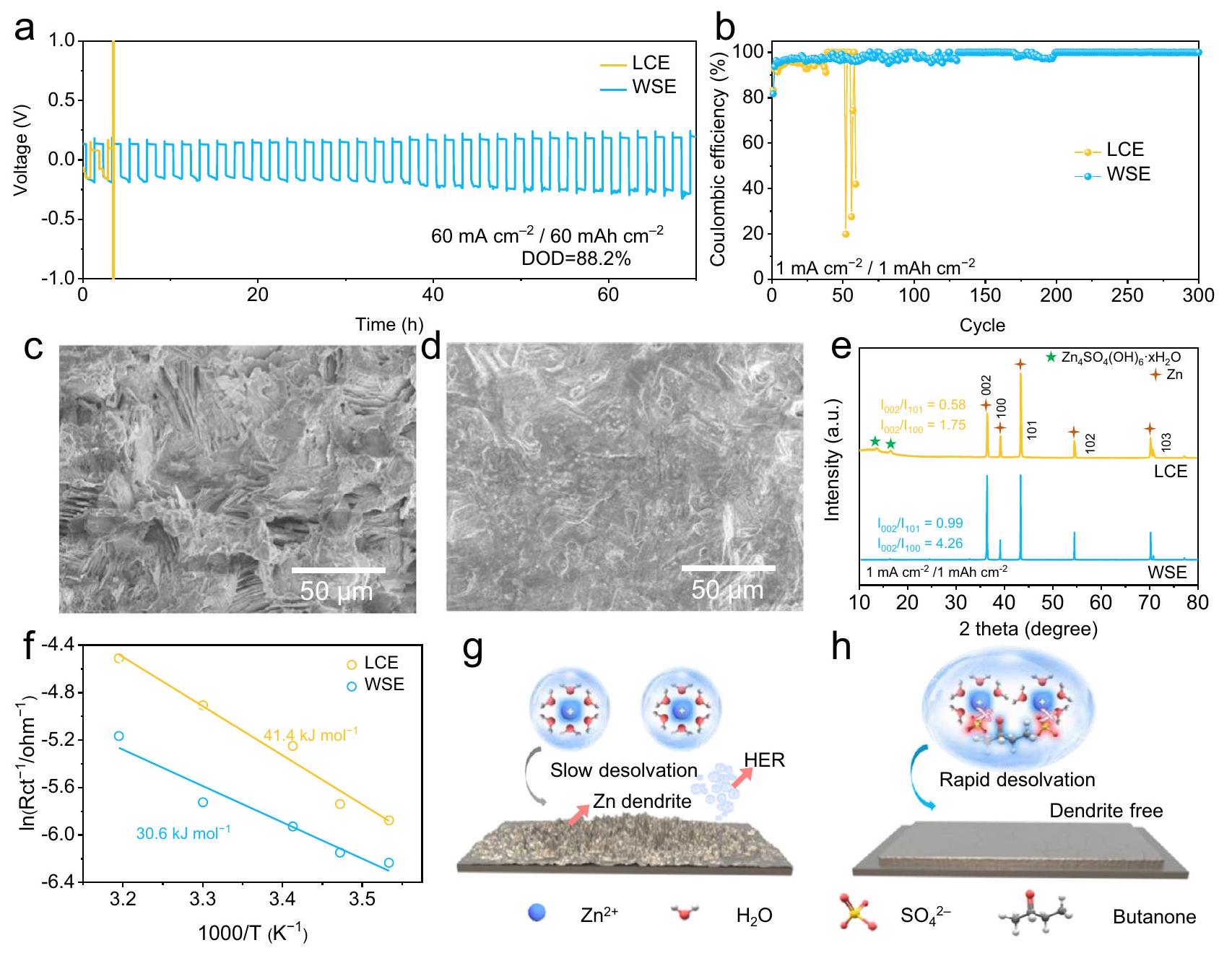
To assess the impact of WSE on the plating/stripping courses of Zn anode, symmetric cells using LCE and WSE were assembled and tested. cells using WSE exhibit improved cycling lifespan over that with LCE at and (Supplementary Fig. 12). More Encouragingly, cells using WSE can still deliver stability for more than 70 h at high current density ( ) and capacity ( ) with a high DOD of while the cells using LCE can not work (Fig. 2a). To the best of our knowledge, such performance far more exceeds the state-of-art Zn anode (Supplementary Table S2). The plating/stripping test was further carried out in Ti/Zn asymmetric cells based on LCE and WSE. As shown in Fig. 2b and Supplementary Fig. 13, after the relatively low CE in the first few cycles which is owing to the lattice fitting, the cells adopting WSE can deliver a high CE of as well as long-term stability ( ). In opposite, the cells using LCE are trapped with short cycling life ( ) and low CE ( ), which could be attributed to the undesirable dendrite growth and HER.
Fig. 2 | Electrochemical performance of anode in WSE and corresponding protection mechanism study. a Galvanostatic cycling profiles of symmetric cells with LCE and WSE at . b Coulombic efficiency (CE) measurements of Ti/Zn cells under different electrolyte systems at . SEM images of Zn foil after 50 cycles at in LCE and WSE. e XRD
pattern of Zn foil cycled after 50 cycles at in LCE and WSE. Plotted charge transfer resistance of Zn/electrolyte interface measured from Zn/ Zn symmetrical cell using LCE and WSE. g Schematic diagram of how Zn anode works in LCE and WSE.
Protection mechenism of WSE for anode
The reason for the enhanced stability of Zn anode in WSE is monitored via SEM, XRD and electrochemical measurements. SEM presents the rough and porous surfaces of Zn anode with irregular Zn dendrite in LCE at after 50 cycles (Fig. 2c), which deteriorate as the current densities and capacities increased to (Supplementary Fig. 14a). In contrary, flat surfaces constituted with densely deposited Zn can be observed at all test conditions in WSE (Fig. 2d and Supplementary Fig. 14b). XRD characterizations were carried out to evaluate the crystal structure of Zn deposits after 50 plating/stripping cycles at . As illustrated in Fig. 2e, the [002] peak of Zn deposits is the strongest in WSE. The intensity ratios of [002] peak to [101] peak are respectively 0.44 and 0.99 for LCE and WSE, suggesting the increased [002] planes for Zn deposits in WSE. Considering the HCP lattice (i.e., space group: ) of Zn metal, it is speculated that the deposited Zn are piled up perpendicular to the c axis, thus leading to a smooth surface as observed from SEM images . When the cycling parameter is changed to , the intensity ratio of [002] peak to [101] peak of Zn in WSE increases to 2.91, indicating more favorable dense deposit of Zn at high rate (Supplementary Fig. 15). In addition, two pronounced peaks at and can be found for Zn plates cycled in LCE, which is due to the HER and the formation of by-products in electrolyte . On the contrary, no characteristic peak of can be found for Zn electrode in WSE, suggesting HER is highly suppressed. The increased corrosion potential further confirms the enhanced anticorrosion ability of WSE for Zn anode protection (Supplementtary Fig. 16).
The deposition process was further understood via electrochemical analysis techniques. The activation energy ( ) for the desoIvation kinetics of ions based on Arrhenius equation in different electrolytes was compared in Fig. 2f. The values are 41.4 and in LCE and WSE electrolytes, respectively, indicating the lower desolvation energy barrier in WSE, which is due to the unique anion type solvation structure of in WSE that facilitates its desolvation process via the electrostatic repulsion effect with negatively polarizated Zn anode . Thanks to the improved desolvation kinetics of in WSE, the further nucleation step of Zn is also boosted. As presented in Supplementary Fig. 18, the nucleation overpotential of Zn electrode in WSE is lower than that in LCE across a range of current densities ( ), which is beneficial for the uniform growth of Zn deposits. Therefore, the enhanced stability of Zn anode in WSE can be attributed to: (i) a water-poor solvation structure is formed in WSE which suppresses HER corrosion and other side reaction; (ii) such solvation structure of is beneficial to fast migration and
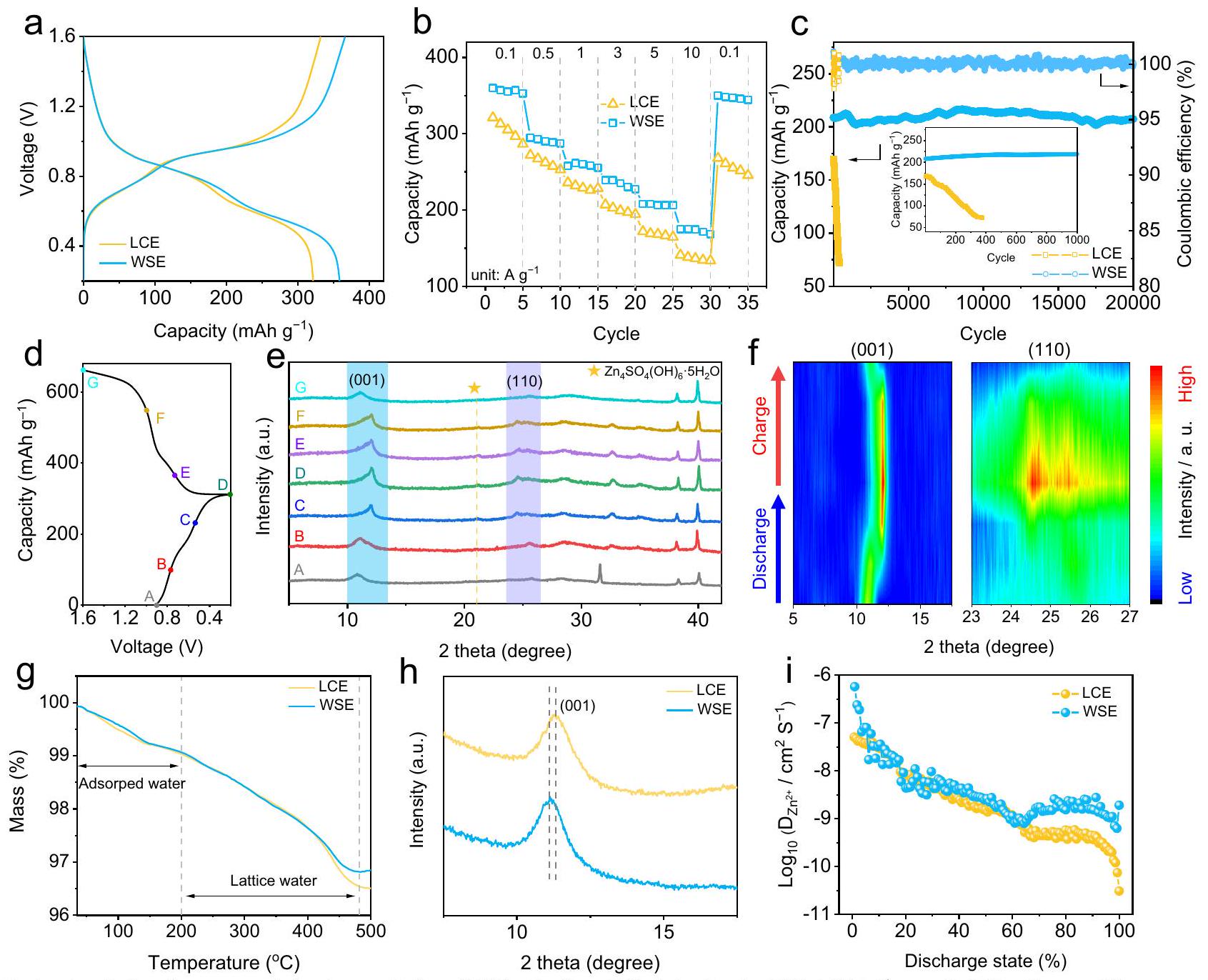
Fig. 3 | Electrochemical performance and structure evolution of NVO cathode in WSE. a GCD curves at rate capability comparison and cycling stability comparison at of NVO cells in LCE and WSE. The inset in Fig. 3c is the enlarged cycling stability at of Zn/NVO cells in LCE and WSE. d GCD curves of
NVO electrode using WSE at , e ex-situ XRD patterns and corresponding contour map. TG curves and XRD patterns of NVO electrode after 50 cycles at in LCE and WSE. i Diffusivity coefficient at various states of discharge in LCE and WSE according to GITT measurement.
desolvation process, which further contribute to the uniform nucleation and growth (Fig. 2g).
Robust cycling stability of cathode materials in WSE
To examine whether WSE affects the cycling sustainability of cathode, full cells were assembled by using NVO as the object of study. Typical scanning electron microscopy (SEM) and X-ray diffraction (XRD) characterization results of NVO can be found in Supplementary Fig. 19. The cyclic voltammetry (CV) curves at initial three cycles of Zn/NVO cell with WSE shows two pairs of redox peaks attributed to and (Supplementary Fig. 20). Note CV curves at the and cycles are almost coincident, indicating its good electrochemical stability. Fig. 3a shows galvanostatic charge-discharge (GCD) curves at of Zn/NVO cells with LCE and WSE, respectively. The capacity superiority of Zn/NVO cells follows the order of WSE and LCE, indicating the addition of butanone can substantially promote the storage ability of NVO. The positive effect of butanone additive is also proved by the rate capability comparison, in which Zn/NVO cell with WSE shows the best capacity retention ( ) from 0.1 to (Fig. 3b and Supplementary Fig. 21). The existence of butanone can also effectively stabilize Zn/NVO cells during cycling. In WSE, the device maintains a high capacity of after 100 cycles at a
moderate rate of , way better than the counterparts with LCE ( , Supplementary Fig. 22). The increase of the test current density to further widens the performance gap of these two devices. Zn/NVO cell with WSE exhibits a capacity retention of 99.1% after 20000 cycles while that with LCE fails quickly after only 400 cycles (Fig. 3c). To highlight the effectiveness of WSE, we compare the cycling stability of Zn/NVO cells with other recently reported works focusing on electrolyte design. As shown in Supplementary Table S3, the capacity retention of Zn/NVO cells using WSE is higher than that of cells based on other electrolyte chemistry, confirming the effectiveness of WSE. Benefitted from the improved anti-freezing ability of WSE, the Zn/NVO cells with WSE can maintain a capacity of after 100 cycles with a capacity retention of at (Supplementary Fig. 23), while its counterpart can barely work. Additionally, the stability of Zn/NVO cells in WSE with a high mass loading cathode ( , denoted as NVO ) was investigated. A high capacity of , a high capacity retention of and a remarkable capacity of after 100 cycles at can be achieved for , indicating the validity of WSE for stabilizing high-capacity V-based AZIBs (Supplementary Fig. 24). More encouragingly, we find that the usage of WSE can also strikingly improve the rate capability and cycling stability of other
AZIBs systems, e. g. cells and cells (Supplementary Figs. 25 and 26), proving the universality of the as-proposed WSE strategy. In addition, the cycling stability of and cells with high cathodic mass loading is presented in Supplementary Fig. 27. Compared to cells using LCE, extended capacity retention of and can be obtained for and cells using WSE. The Ragone plots of and cells using WSE are shown in Supplementary Fig. 28 (based on the mass loading of cathode materials), in which energy densities of 269, 170.5, and 360.2 Wh kg are obtained for and cells.
Protection mechanism of WSE for cathode
To investigate the underlying reason for the differentiated electrochemical performance of Zn/NVO cells in different electrolytes, several ex-situ characterizations were conducted to monitor the structure and valence change of NVO cathode during repeated charge/discharge processes. Fig. 3e, f displayed the ex-situ XRD patterns of NVO in WSE at representative discharge (A-D) and charge (D-G) states (Fig. 3d). Note that the reversible appearance (discharge to D ) and disappearance (charge to G ) of the peak at can be assigned to , suggesting the existence of reversible insertion/extraction behaviors in the NVO electrode . Zn XPS spectra reveal the reversible insertion/extraction mechanism of NVO electrode, in which the strong intensity of spectra at state D indicates the insertion of while it becomes weaker at state G (Supplementary Fig. 29). The positive shift of Zn 2 p spectra is due to the formation of at state D , in good agreement with the XRD results. In addition, the (001) plane gradually shifts from to at state D and then recover to its initial 2 theta degree upon state G , suggesting the decreased d -space of (001) plane at state D. Conversely, the negative shift of (110) plane can be observed at state D, indicating the increased d-space of (110) plane (Fig. 3f). Such phenomenon is due to the polarity of inserted and their hydrated ions that cause structure aberration. To highlight the difference between NVO cycled in LCE and WSE, we dissected the Zn/NVO cells with LCE and WSE after 50 cycles at a low current density of . We set the cutoff voltage of NVO with both electrolytes as 1.6 V (fully charged state) to investigate the inserted lattice into NVO in different electrolytes. Several characterizations including thermogravimetry (TG), XPS, XRD and SEM were performed to evaluate the structure evolution of different NVO electrodes. In TG curves, the weight loss above could be attributed to the loss of lattice . Fig. 3 g suggests the NVO cycled in WSE shows less loss of lattice , indicating the amount of co-inserted is decreased to some extent. XPS spectra further confirm the decreased of NVO with WSE, as the intensity of peak representing at 532.5 eV of NVO with WSE is lower than that with LCE (Supplementary Fig. 30). As shown in Fig. 3h, the XRD of NVO cycled in LCE experiences a more obvious lattice expansion than that in WSE ( to ), as revealed by the more deviated (001) plane from the pristine NVO, suggesting the mitigatory lattice variation of NVO in WSE. Such lattice expansion of NVO in LCE may cause strain and the consequent crack formation, as revealed by SEM images (Supplementary Fig. 31). Much more cracks were formed on the NVO electrode cycled in LCE while a flat surface is observed for NVO cycled in WSE, indicating the protective ability of WSE for NVO at the electrode level. Based on the above experimental results, it can be concluded that co-insertion happens in both LCE and WSE, except more is co-inserted into NVO in LCE during the cycling process. Moreover, the insertion of a suitable amount of is beneficial for the energy storage process of NVO while excess insertion of can cause capacity fading. In addition to the structure deformation, the cathode dissolution should also be paid attention for the capacity decay of NVO. NVO electrodes were first immersed in LCE and WSE for 7 days to test their solubility. As shown in Supplementary
Fig. 32, the bottle containing WSE shows a lighter yellow compared with the LCE, indicating the dissolution of NVO is diminished by butanone. We further performed the dissolution test in 2032-type coin cells, in which electrolytes were used. After resting for 7 days, the separators of cells with LCE and WSE were taken out and further used for the inductively coupled plasma (ICP) test. As shown in Supplementary Fig. 33, the atom ratio of V element for LCE and WSE is and , indicating that WSE can highly suppress the dissolution of NVO under the actual working condition. XRD patterns of NVO soaked in LCE and WSE for 7 days are shown in Supplementary Fig. 34. The (001) and (110) planes of NVO soaked in both LCE and WSE show no deviate from the pristine NVO except the (001) plane of NVO soaked in LCE is missing, indicating the structure of NVO is destroyed in LCE due to the dissolution issue. To highlight the negative impact of cathode dissolution on the overall performance of Zn/ZVO, NVO electrodes that underwent the dissolution tests (resting the NVO cells with LCE and WSE for 7 days) were subjected to GCD tests. Compared to the cells that did not experience the dissolution test (Fig. 3a), the NVO electrodes tested in LCE and WSE show capacity loss of 44.4 % and 7.8 % in the first cycle, respectively, indicating the WSE can also suppress the cathode dissolution of NVO (Supplementary Fig. 35).
The reaction kinetics of NVO in different electrolytes were instigated by EIS, CV and galvanostatic intermittent titration technique (GITT). The EIS spectra of Zn/NVO full cell with LCE and WSE after activation are shown in Supplementary Fig. 36. Zn/NVO full cell with WSE shows smaller Warburg resistance ( ) than that in LCE, indicating the facilitated ion transfer process for ion storage due to the changed solvation structure of . CV curves of the NVO cells are tested at various scan rates ( , Supplementary Fig. 37). The b values for NVO in WSE are 0.576, 0.609, 0.636, and 0.624, implying the charge storage process is synergistically controlled via a combination of ionic diffusion and capacitance behaviors. Note both values and capacitance contribution at all scan rates of Zn/NVO cells using WSE are higher than that in pure electrolytes, suggesting the faster reaction kinetics of NVO in WSE. GITT measurement was performed to evaluate the ion-diffusion coefficient ( ) in NVO cathode (Fig. 3i and Supplementary Fig. 38). The ion diffusion coefficient ( ) at low DOD reflects the insertion kinetics while at high DOD represents the insertion kinetics. The of insertion is similar in LCE and WSE, indicating the introduction of butanone has a negligible effect on insertion kinetics. However, the of insertion in WSE is higher than that in LCE, suggesting the faster insertion kinetics with newly recruited butanone in WSE. This phenomenon is because that (i) WSE shows boosted desolvation kinetics; (ii) the overdosed co-inserted is minished in WSE. The excess insertion of in LCE can block the insertion pathway, thus increasing the insertion resistance . On the opposite, the transformed solvation structure of with butanone additive can facilitate the desolvation process of and decrease the amount of co-inserted . Therefore, the protection mechanism of WSE for NVO can be concluded as: (i) the excess co-insertion of is suppressed and the structure aberration/collapse of NVO during cycling is relieved; (ii) the dissolution of NVO is greatly mitigated because the activity of is reduced owing to the intense hydrogen bonding interaction between and butanone.
Fabrication of AA-type Zn/NVO cell based on WSE
AA-type batteries are used in a wide range of scenarios in daily life, which request battery systems with high safety, performance, and sustainability. Therefore, to further testify the feasibility of WSE for practical application, rechargeable AA type Zn/NVO cells (denoted as AA-Zn/NVO) based on WSE were assembled (Fig. 4a). This cell prototype is realized by rolling NVO electrode, brown paper separator and Zn foil to tight and fill them into stainless steel
Fig. 4 | Electrochemical performance of AA-Zn/NVO cells. a Schematic illustration of AA-Zn/NVO cells. GCD curves at cycling stability at 0.66 C of AA cells and selected GCD curves of 1st, 15th and 30th cycles at 0.66 C . e Digital images of remote-controlled car powered by AA-Zn/NVO cells. The insets
in Fig. 4 b and e are the optical images of as-fabricated cells. Comparison of WSE-based AZIBs with other reported AZIBs based on other different electrolyte chemistry.
cylinder (Supplementary Fig. 39). Different from the most reported studies relying on laboratory-scale coin cells with high N/P and E/C ratios, much lower N/P and E/C ratios is achieved in this AA-type cell (Supplementary table S4). To avoid potential electrolyte decomposition, the voltage window of is compressed down to . A satisfying capacity of was obtained at 0.66 C -rate, which is closed to the theoretical capacity of NVO cathode and even comparable to some commercial zinc manganese dry battery (Fig. 4b). More importantly, the selected GCD curves of AAZn/NVO at the 1st, 15th, and 30th cycles show no obvious capacity loss or voltage hysteresis, proving it can support very stable long cycling as well as high CE (Fig. 4c and d). The NVO and Zn electrodes of the device after cycling assessment were taken out for further SEM characterization. The SEM images of the NVO electrode after cycling show no significant change while Zn foil presents a smooth surface (Supplementary Fig. 40). All the above advantages support our proposed WSE can stabilize both NVO cathode and Zn anode, even in a practical rechargeable AA-type cell system. As a proof of concept, the integrated AA-Zn/NVO with WSE can provide sufficient power to drive a remotecontrolled car (Fig. 4e and Supplementary Movie 1). Taking all factors including capacity, rate capability, cycle life and cost into consideration, it is reasonable to expect that such WSE could outperform the most advanced AZIBs designed via other different electrolyte chemistry (Fig. 4f).
Discussion
In summary, we developed a promising WSE for highly sustainable AZIBs by simultaneously stabilizing the cathode and Zn anode. This was achieved by using butanone as an anti-solvent to lower the solvating power of , and thus reduce the solvated to form a water-poor solvation structure to relieve the structure aberration/collapse of cathode during cycling as well as dendrite growth and side reactions on Zn anode. As a proof of concept, excellent stability of the Zn anode at the test condition and DOD) is achieved. Moreover,
three typical AZIBs including , and AZIBs using WSE were assembled and exhibited excellent cycling stability. The effectiveness of WSE for AZIBs is further demonstrated in AA-Zn/NVO, of which a high capacity of 101.7 mAh and high stability of 96.1% capacity retention after 30 cycles were achieved. Although there is still much to explore, such as the search for better-performing cathode and the manufacturing technique for higher mass loading cathode ( ), this electrolyte design strategy takes the first step toward realizing the high sustainability of AZIBs.
Methods
Electrolyte preparation
LCE was prepared by dissolving 5.75 g of into 40 mL of deionized water to form transparent solutions. To prepare WSE, 5.75 g of is added to a mixed solution containing 5 mL of butanone and 35 mL of deionized water until the solutions become transparent. The concentation of in WSE is 0.5 M .
Cathode preparation
was prepared by adding 2 g of commercial into 2 M NaCl aqueous solution ( 30 mL ) under stirring for 4 days at . The dark red product was washed with deionized (DI) water several times and obtained after freeze-drying for was prepared by dissolving and 0.7 g sodium dodecyl sulfate (SDS) in 20 mL deionized water to form solution A. Then, 20 mL aqueous solution is slowly added into solution A. After aging at room temperature for 24 hours, the products are washed several times with DI water. The samples are finally achieved after freeze-drying for (MA-EN-CA-1U015Y) was purchased from Canrd Technology Co. Ltd. and used without any treatment. Take the NVO electrode as an example, NVO was mixed with carbon black and poly(vinylidene fluoride) binder at a weight ratio of 8:1:1 in 1-methyl-2-pyrrolidinone (NMP). The slurry was pasted on Ti foil ( 0.3 mm thickness), and dried overnight at . The total mass loading of the electrode was .
Fabrication of AA-type battery
The NVO cathode was prepared as the same routine which we have described in the above section. The total mass loading of the electrode was . Zn foil with 0.3 mm thickness was selected as the anode and brown paper was used as separator. The cathode, separator, and anode were rolled too tight and filled into a stainless steel cylinder. The tabs of NVO cathode and Zn anode were bonded by the tab film (MTI) via hot-pressing. The stainless steel cylinder is sealed after the injection of 2.0 g WSE. The sealing procedure was conducted by the automated vacuum sealing machine (Wuhan Geruisi New Energy Co., Ltd). The obtained AA-type battery was rested for an hour before the electrochemical test.
Materials characterization
Raman spectroscopy (Renishaw inVia), Fourier-transform infrared spectroscopy (Vertex70Hyperion3000), and nuclear magnetic resonance (Varian INOVA500NB) were used to investigate the solvation structures of . Differential scanning calorimetry and ionic conductivity of different electrolytes were tested by DSC-204 F1 and Leici DDS-11A. Field-emission SEM (JSM-6330F), XRD (D-MAX 2200 VPC, RIGAKU) TG (TG209F1 Libra R), and XPS (NEXSA, Thermo FS) were performed to study the microstructures and compositions of Zn anode and NVO cathode.
Electrochemical measurements
CV, GCD, GITT, and EIS measurements were conducted on CHI 760E electrochemical workstation and Neware battery system (CT-3008-5V , Shenzhen, China). For galvanostatic cycling of symmetric cells, 2032-type coin cells were assembled with Zn foil (N-buliv Co., Ltd., 1 mm thickness) as cathode and anode, glass fiber (Whatman GF/D) as separator. For the Zn plating/stripping test, Zn foil was used as counter electrode, and Ti plate ( 1 mm thickness) was employed as working electrode. The stripping cut-off voltage was set at 0.5 V (vs. ) for each cycle. The electrochemical characterizations of the NVO, and cells were performed in 2032-type coin cells or AA-type cells with different electrolytes. The voltage window for and coin cells are , , and , respectively. For EIS measurement, the applied frequency is between and . In the GITT study, a cell was discharged at rate for 30 s , followed by a 10 min open circuit step to allow relaxation back to equilibrium. The procedure was continued until the discharge voltage reached 0.2 V . All electrochemical tests were carried out in an environmental chamber at a constant temperature of . The energy density ( E ) and power density ( P ) of NVO, and coin cells were calculated from GCD curves according to Eqs. (2) and (3), respectively, where I is the discharging current, U is the voltage, and t is the discharging time.
Theoretical calculations
Force-field molecular dynamics (FFMD) simulations were performed using the MD software Material Studio. The forced field parameters were obtained from Universal fields. The size of box is , and periodic boundary conditions were set in both directions. The simulation cells contained and (LCE) and and 4 butanone (WSE), respectively. Ewald methods were applied to compute electrostatic interactions. For the calculation of electrostatic/non-electrostatic interactions in real space, the cut-off length was set as 0.6 nm and the integration time
step was 1 fs. The system was annealed from 200 to 500 K over 0.5 ns and then run for 2.0 ns to reach equilibrium. Temperature simulations were performed using the Nose method. For the post-processing analysis, a 5 ns production simulation was performed.
Data availability
All data that support the findings of this study are provided within the paper and its Supplementary Information. All additional information is available from the corresponding authors upon request. Source data are provided with this paper.
References
Li, C., Jin, S., Archer, L. A. & Nazar, L. F. Toward practical aqueous zinc-ion batteries for electrochemical energy storage. Joule 6, 1733-1738 (2022).
Yang, C. et al. All-temperature zinc batteries with high-entropy aqueous electrolyte. Nat. Sustain. 6, 325-335 (2023).
Zhang, Q. et al. Designing anion-type water-free solvation structure for robust Zn metal anode. Angew. Chem. Int. Ed. 133, 23545-23552 (2021).
Zhao, R. et al. Lanthanum nitrate as aqueous electrolyte additive for favourable zinc metal electrodeposition. Nat. Commun. 13, 3252 (2022).
Zheng, J. et al. Reversible epitaxial electrodeposition of metals in battery anodes. Science 366, 645-648 (2019).
Shi, X. et al. Compacting electric double layer enables carbon electrode with ultrahigh Zn ion storage capability. Angew. Chem. Int. Ed. 61, e202214773 (2022).
Zhu, Z. et al. Rechargeable batteries for grid scale energy storage. Chem. Rev. 122, 16610-16751 (2022).
Han, D. et al. A non-flammable hydrous organic electrolyte for sustainable zinc batteries. Nat. Sustain. 5, 205-213 (2022).
Wan, F. et al. Aqueous rechargeable zinc/sodium vanadate batteries with enhanced performance from simultaneous insertion of dual carriers. Nat. Commun. 9, 1656 (2018).
Zeng, Y. et al. Construction of Co-Mn Prussian blue analog hollow spheres for efficient aqueous Zn -ion batteries. Angew. Chem. Int. Ed. 60, 22189-22194 (2021).
Chao, D. et al. Atomic engineering catalyzed electrolysis kinetics for a hybrid aqueous battery with high power and energy density. Adv. Mater. 32, 2001894 (2020).
Zhu, Y., Cui, Y. & Alshareef, H. N. An anode-free battery. Nano Lett. 21, 1446-1453 (2021).
Wang, C. et al. Toward flexible zinc-ion hybrid capacitors with superhigh energy density and ultralong cycling life: The pivotal role of salt-based electrolytes. Angew. Chem. Int. Ed. 60, 990-997 (2021).
Kim, Y. et al. Corrosion as the origin of limited lifetime of vanadium oxide-based aqueous zinc ion batteries. Nat. Commun. 13, 2371 (2022).
Yang, K. et al. Triple-functional polyoxovanadate cluster in regulating cathode, anode, and electrolyte for tough aqueous zinc-ion battery. Adv. Energy Mater. 12, 2202671 (2022).
Liu, C., Xie, X., Lu, B., Zhou, J. & Liang, S. Electrolyte strategies toward better zinc-ion batteries. ACS Energy Lett. 6, 1015-1033 (2021).
Jiang, H. et al. Chloride electrolyte enabled practical zinc metal battery with a near-unity Coulombic efficiency. Nat. Sustain. (2023) https://doi.org/10.1038/s41893-023-01092-x.
Huang, C. et al. Stabilizing zinc anodes by regulating the electrical double layer with saccharin anions. Adv. Mater. 33, e2100445 (2021).
Chen, Y. et al. A Multifunctional anti-proton electrolyte for high-rate and super-stable aqueous Zn -vanadium oxide battery. Nano-Micro Lett. 14, 154 (2022).
Yang, F. et al. Understanding evolution electrochemistry to minimize solvated water impact on Zinc-anode performance. Adv. Mater. 34, 2206754 (2022).
Wang, F. et al. Highly reversible zinc metal anode for aqueous batteries. Nat. Mater. 17, 543-549 (2018).
Cao, L. et al. Solvation structure design for aqueous Zn metal batteries. J. Am. Chem. Soc. 142, 21404-21409 (2020).
Liu, S. et al. Tuning the electrolyte solvation structure to suppress cathode dissolution, water reactivity, and Zn dendrite growth in zinc-ion batteries. Adv. Funct. Mater. 31, 2104281 (2021).
Qin, R. et al. Tuning coordination environment to suppress dendrite formation for high-performance Zn -ion batteries. Nano Energy 80, 105478 (2021).
Qiu, H. et al. Zinc anode-compatible in-situ solid electrolyte interphase via cation solvation modulation. Nat. Commun. 10, 5374 (2019).
Yao, Y. et al. Regulating interfacial chemistry in lithium-ion batteries by a weakly solvating electrolyte. Angew. Chem. Int. Ed. 60, 4090-4097 (2021).
Yang, Y. et al. Weakly solvating effect spawning reliable interfacial chemistry for aqueous Zn/Na hybrid batteries. Adv. Energy Mater. 13, 2203729 (2023).
Yang, H. et al. A Metal-organic framework as a multifunctional ionic sieve membrane for long-life aqueous zinc-iodide batteries. Adv. Mater. 32, e2004240 (2020).
Zhou, M. et al. Surface-preferred crystal plane for a stable and reversible zinc anode. Adv. Mater. 33, e2100187 (2021).
Hao, J. et al. An in-depth study of Zn metal surface chemistry for advanced aqueous Zn-ion batteries. Adv. Mater. 32, 2003021 (2020).
Ma, T. et al. Optimize lithium deposition at low temperature by weakly solvating power solvent. Angew. Chem. Int. Ed. 134, e202207927 (2022).
Liang, W. et al. cathode stabilized by in situ phase transformation for aqueous zinc-ion batteries with ultra-long cyclability. Angew. Chem. Int. Ed. 134, e202207779 (2022).
Huang, J. et al. In situ induced coordination between a “desiccant” interphase and oxygen-deficient navajoite towards highly efficient zinc ion storage. Adv. Energy Mater. 12, 2201434 (2022).
Acknowledgements
This work is financially supported by the Guangdong Basic and Applied Basic Research Foundation (2022A1515140008), and the Guangdong Province Innovation and Strong School Project (2020ZDZX2004).
Author contributions
X.L. planned and designed the project. Z.Y., X.S, and J.W. fabricated the materials and performed the electrochemical experiments. J.X. analyzed the data. X.L., X.S., Z.Y., and S.X. wrote the manuscript. All authors discussed the results and commented on the manuscript.
Correspondence and requests for materials should be addressed to Shilei Xie, Zujin Yang or Xihong Lu.
Peer review information Nature Communications thanks Guanjie He, Kevin Huang, and Minjoon Park for their contribution to the peer review of this work. A peer review file is available.
MOE of the Key Laboratory of Bioinorganic and Synthetic Chemistry, The Key Lab of Low-carbon Chem & Energy Conservation of Guangdong Province, School of Chemistry, School of Chemical Engineering and Technology, Sun Yat-Sen University, Guangzhou, PR China. School of Environment and Civil Engineering, Guangdong Engineering and Technology Research Center for Advanced Nanomaterials, Dongguan University of Technology, Dongguan, PR China. e-mail: xieshil@dgut.edu.cn; yangzj3@mail.sysu.edu.cn; luxh6@mail.sysu.edu.cn