استراتيجية استبدال لتنظيم البيئة المحلية لمحفزات Co-SxN4−x ذات الذرة الواحدة لتسهيل اختزال CO2 A replacement strategy for regulating local environment of single-atom Co-SxN4−x catalysts to facilitate CO2 electroreduction

المجلة: Nature Communications، المجلد: 15، العدد: 1
DOI: https://doi.org/10.1038/s41467-023-44652-7
PMID: https://pubmed.ncbi.nlm.nih.gov/38195701
تاريخ النشر: 2024-01-10

استراتيجية استبدال لتنظيم البيئة المحلية للذرة المفردة محفزات لتسهيل الاختزال الكهربائي

تاريخ الاستلام: 25 أغسطس 2022
تم القبول: 21 ديسمبر 2023
نُشر على الإنترنت: 10 يناير 2024
(أ) التحقق من التحديثات

جياجينغ بي هويشان شانغ جونجي ماو © Zhe Chen (1) روي سوي شويجيانغ تشانغ داني زو يو وانغ فانغ تشانغ وي زو ) تاو وانغ وينشينغ تشين ² وزونغبين زوانغ

الملخص

تتحكم البيئات التنسيقية المحلية في أداء المحفزات ذات الذرة الواحدة. هنا، تم تطوير استراتيجية استبدال حراري لتخليق المحفزات ذات الذرة الواحدة مع بيئات تنسيقية محلية مضبوطة وقابلة للتعديل بدقة. سلسلة من تم تصنيع المحفزات أحادية الذرة بنجاح عن طريق استبدال النيتروجين المنسق بالكبريت حرارياً عند درجات حرارة مرتفعة، وهناك علاقة بركانية بين التنسيقات والأداءات التحفيزية تجاه التفاعلات الكهروكيميائية. يتم ملاحظة الانخفاض. المحفز لديه التوازن و الارتباطات، وبالتالي يقع في قمة البركان مع أعلى أداء نحو الكهروكيميائية التحويل إلى CO، مع أقصى كفاءة فاراداي لـ CO تبلغ وتردد عالي للتغيير عند جهد زائد قدره 410 مللي فولت تم اختباره في خلية H -مشبع ، متجاوزًا معظم المحفزات ذات الذرة الواحدة المبلغ عنها. يوفر هذا العمل نهجًا منطقيًا للتحكم في البيئة التنسيقية المحلية لمحفزات الذرة الواحدة، وهو أمر مهم لمزيد من الضبط الدقيق للأداء التحفيزي.

المحفزات ذات الذرة الواحدة (SACs)، باعتبارها محفزات ناشئة تتمتع ببيئة كيميائية فريدة للمعادن المركزية واستخدام عالي للمعادن المركزية، أظهرت إمكانيات كبيرة في كل من التحفيز الحراري والكهربائي. . بشكل خاص، تُظهر SACs إمكانيات عالية في الكيمياء الكهربائية تفاعل اختزال )، والتي تعتبر وسيلة جذابة لتنظيم الغلاف الجوي تركيزات من خلال استخدام SACs، يتم تحقيق انتقائية عالية تجاه يمكن تحقيقه، مفيد من المراكز النشطة المعدنية المعزولة الفريدة . وبالتالي، فإن فهم علاقة الهيكل بالأداء وتصميم SACs عالية الأداء هو أمر مهم في العمليات الحفزية.
لتصميم محفز عالي الأداء، يجب أن يأخذ في الاعتبار ليس فقط المعادن المركزية، ولكن أيضًا البيئة التنسيقية المحلية للمعادن المركزية. في عملية التحفيز غير المتجانسة، تمتص المتفاعلات على سطح المحفزات وتتحول إلى منتجات. وبالتالي، فإن طاقات الربط للمحفزات مع الوسائط تكون حاسمة لعملية التحفيز. تُحدد طاقة الربط من خلال التركيب الإلكتروني للمركز النشط، الذي يتحكم فيه بيئته التنسيقية المحلية. لقد أثبتت عدة أمثلة الأدوار الحاسمة لبيئة التنسيق المحلية في الأداء التحفيزي. أظهر وو وآخرون أن المواقع كانت كثيرة
أكثر كفاءة من مواقع للتقليل الانتقائي إلى عيب الفراغ تمت دراسة الموقع بواسطة لو وآخرون، وكان أكثر نشاطًا من موقع لـ من خلال استبدال الذرة المنسقة بذرات أخرى، يمكن تعديل نشاط المعادن المركزية أيضًا. أفاد فنغ وآخرون أن الإزاحة الجزئية للنيتروجين بواسطة ذرات الكبريت في المعادن الانتقالية المنسقة – يمكن أن يحسن بشكل كبير نشاط تفاعل تطور الأكسجين أظهر وانغ وآخرون أن الفوسفور والنيتروجين مرتبطان. قد عزز أداء تطور الهيدروجين أكثر من موقع . لقد أظهر أن البيئة التنسيقية المحلية للمعادن المركزية تحدد الأداء التحفيزي لـ SACs. ومع ذلك، لا تزال هناك نقص في الطرق الاصطناعية الفعالة لضبط البيئة التنسيقية المحلية لـ SACs. على عكس المحفزات المتجانسة، التي تحتوي على مواقع معدنية في بيئات تنسيقية محددة جيدًا، فإن البيئات التنسيقية المحلية لـ SACs يصعب التحكم فيها بسبب المواقع السطحية المتنوعة للمحفزات غير المتجانسة. تُركب SACs ببيئة تنسيق معينة دائمًا بواسطة مسار محدد، ولكن من الصعب تركيب سلسلة من SACs ببيئات تنسيق قابلة للتعديل. تعتبر SACs ذات البيئة التنسيقية غير المتناظرة مع روابط مختلفة صعبة بشكل خاص في التحكم في هيكلها، بسبب التفاعلية المختلفة للذرات المنسقة في التركيب. هناك حاجة إلى طرق تركيب أكثر قابلية للتحكم لـ SACs، لكنها لا تزال تمثل تحديًا.
هنا، نعرض استراتيجية استبدال حراري لضبط البيئة التنسيقية المحلية لـ SACs، وسلسلة من SACs ببيئة تنسيقية محلية قابلة للتحكم. تمت تخليقها بنجاح. المتناظر تم توليد S أولاً، وتم استبدال N بـ S الإضافي عند درجة حرارة مرتفعة لتشكيل S المستبدل. SACs. كانت عملية الاستبدال التدريجي تضمن التحكم الدقيق في البيئة التنسيقية المحلية لـ SACs، واستنادًا إلى هذه السلسلة من SACs، التنسيق- تم التحقيق في علاقة الأداء. تم تأكيد البيئات التنسيقية المحلية المضبوطة بدقة لسلسلة SACs بواسطة مطيافية امتصاص الأشعة السينية (XAS)، وحالات التكافؤ لـ تم ضبط السلاسل بشكل مستمر. تظهر حسابات تحويل فورييه السريع أن شحنة بادير يمكن تعديلها بشكل مستمر من خلال زيادة عدد تنسيق الكبريت، مما يعزز باستمرار الارتباط بالوسطاء لـ (أي، * COOH و * CO ). تم ملاحظة اتجاه نشاط بركاني مقابل رقم الإحداثيات في SACs. الـ لديه توازن * COOH و * CO الامتزاز، مما يعطي أعلى تقليل أداء أول أكسيد الكربون، والذي لديه كفاءة فاراداي قصوى لأكسيد الكربون ( ) من وتردد دوران مرتفع (TOF) لـ عند جهد منخفض قدره 410 مللي فولت، متجاوزًا معظم SACs المبلغ عنها. يوفر هذا العمل استراتيجية فعالة لضبط البيئة التنسيقية المحلية لـ SACs بدقة، مما يوفر ضبطًا دقيقًا للهيكل الإلكتروني لمواقع المعادن المركزية ويعزز الأداء التحفيزي.

النتائج

تخليق وتوصيف الـ ( ) SACs
تم تصنيع سلسلة SACs من خلال عملية التحلل الحراري المنضبط لجزيئات نانوية من ZIF-8 المضافة بالكوبيك. أظهرت الدراسات السابقة أن M- المواقع التي تشكلت فوق عن طريق التحلل الحراري لـ ZIF المدعوم بالمعادن . ومع ذلك، حدث فقدان للمواد المضافة من نوع N عند درجات حرارة أعلى . من خلال إدخال مصدر إضافي للكبريت من الثيوفين، تم استبدال النيتروجين مع فقدان النيتروجين، مما أدى إلى تعديل البيئة التنسيقية المحلية لذرات المعدن المركزية. من خلال التحكم في درجة حرارة التحلل الحراري، تم التحكم في فقدان المواد المضافة من النيتروجين، وتم التحكم بشكل تلقائي في مستوى المواد المضافة من الكبريت. ونتيجة لذلك، تم إنتاج سلسلة من SACs مع بيئة تنسيق كوبرية محكومة، أي، ، و تمت عملية التخليق بنجاح. النهج التخليقي لسلسلة من تم توضيح SACs بشكل تخطيطي في الشكل 1a.
أولاً، تم تحضير Co-ZIF-8 من خلال عملية قائمة على المحلول، وتم عرض صورة المجهر الإلكتروني الماسح (SEM) في الشكل التكميلية 1، مما يدل على الحجم الموحد للمنتجات. ثم تم تحميصه للحصول على SACs تحت درجة حرارة معينة. الـ تم الحصول عليه عن طريق التحلل الحراري المباشر لـ ZIF- 8 في دون إضافة مصادر S. الـ و تم الحصول على SACs من خلال التحلل الحراري مع مصادر إضافية للكبريت عند 900 و 1000 و ، على التوالي. صور المجهر الإلكتروني الناقل (TEM) للعينات المستخلصة تظهر SACs في الشكل 1b و e و h و k، على التوالي. تظهر أشكالها متعددة الأوجه مشابهة بحجم يقارب 200 نانومتر. ومع ذلك، مع زيادة درجة حرارة التفاعل، أي مع زيادة المحتويات في المنتجات، تصبح الجسيمات النانوية أكثر خشونة وذات مسام أكبر. وقد أكدت على كسر الـ المجموعات عند درجات حرارة عالية، مما جعل المواد مسامية تمت دراسة المساحة السطحية المحددة والمسامية بشكل إضافي من خلال إيزوثرمات امتصاص-إزالة النيتروجين (الشكل التكميلي 2a)، وتم إدراج حجم المسام الدقيقة، وحجم المسام المتوسطة، ومساحة بروناوير-إيميت-تيلر في الجدول التكميلي 1. )، مساحة السطح الميكروية ( )، مساحة السطح الخارجية ( ) من أجل الـ SACs. الـ أظهرت SACs نتائج قابلة للمقارنة من ، و لـ ، و SACs، على التوالي. مع زيادة محتوى الكبريت، يزداد بشكل طفيف. جاء زيادة المساحة السطحية بشكل رئيسي من زيادة ، مما يدل على حفر الجسيمات النانوية. زاد إجمالي حجم المسام مع زيادة المحتوى أيضًا، خاصة بالنسبة للمسامات المتوسطة. الشكل التوضيحي الإضافي 2b يظهر منحنيات توزيع حجم المسام لـ أصبحت المسام أكبر مع زيادة مكون S، بسبب تأثير النقش عند درجات الحرارة المرتفعة.
تظهر صور المجهر الإلكتروني الناقل المظلم الحلقي عالي الزاوية مع تصحيح الشذوذ (AC HAADFSTEM) المقابلة في الشكل 1c و f و i و l. يتم ملاحظة نقاط ساطعة متناثرة بوضوح، والتي تم تمييزها بدوائر حمراء. تُنسب هذه النقاط الساطعة إلى ذرات الكوبالت الفردية، بسبب أعدادها الذرية الأعلى من الـ و S. تشير هذه النتائج إلى أن الكوبالت كان موزعًا ذريًا في مصفوفة الكربون. الصور المقابلة لتخطيط طيف الأشعة السينية المشتتة للطاقة (EDS) لـ موضحة في الشكل 1d، و م. يكشف أن وC كانت موزعة بشكل موحد في الركائز. أنماط حيود الأشعة السينية (XRD، الشكل التكميلي 3) من تظهر العينات فقط القمم المخصصة للجرافيت، ولم يتم ملاحظة أي قمم أخرى، مثل تلك المنسوبة إلى CoO أو CoS. كما يشير ذلك إلى أن الكوبالت موزع ذريًا في الركائز الكربونية. محتوى الكوبالت في السلسلة تم قياس العينات بواسطة تحليل ICP-OES (الجدول التكميلي 2)، حيث قدمت نسبة وزن مشابهة في النطاق من 0.53 إلى العنصر الخفيف (أي، محتويات الـ تم قياس SACs بواسطة محلل عنصري (الجدول التكميلي 3). كانت محتويات الهيدروجين لـ كانت SACs أقل من ، مما يشير إلى أن المواد السابقة تم كربنتها بشكل جيد خلال عمليات التحلل الحراري. ومع ذلك، أظهرت SACs محتويات عالية من النيتروجين والكبريت مقارنة بمحتويات الكوبالت، مما يشير إلى أن النيتروجين والكبريت لم يكونا مرتبطين فقط بالكوبالت، بل كانا موجودين أيضًا في الركيزة الكربونية.
البيئات التنسيقية المحلية لـ ( ) SACs
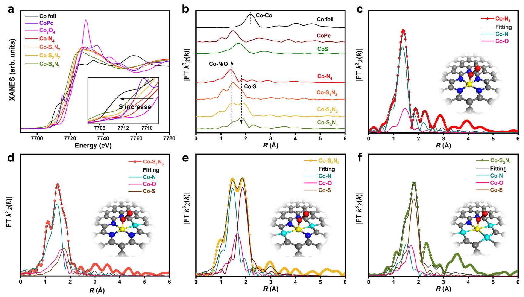
البيئات التنسيقية المحلية المفصلة لـ Co المستخرج تمت دراسة SACs باستخدام هيكل امتصاص الأشعة السينية القاسي بالقرب من الحافة (XANES) وهيكل الامتصاص الدقيق الممتد بالأشعة السينية بواسطة تحويل فورييه (FT-EXAFS). الشكل 2a يظهر طيف XANES لحدود Co K المعدلة. وعينات المرجع. يوضح الشكل المرفق المناطق المكبرة من حافة الامتصاص. بالمقارنة مع رقائق الكوبالت، فإن حواف الامتصاص لـ Co- تتحول SACs نحو طاقة أعلى، مما يظهر الشحنات الإيجابية على ذرات الكوبالت. ومع ذلك، مقارنةً بـ ، يظهرون حالة أقل من حيث القيمة لعناصر الكوبالت في SACs، الناتجة عن الظروف المحلية الفريدة
بيئات التنسيق لـ SACs. تم العثور على تأثير الضبط الإلكتروني على مع مختلف أرقام التنسيق، مما يدل على الحساسية القوية تجاه البيئات التنسيقية المحلية. حالات التكافؤ للكوبيوم في هذه تنخفض SACs تدريجياً عندما تزداد كمية S، بسبب انخفاض الكهربية السالبة لـ S مقارنة بـ N. يتم ملاحظة قمة حادة قبل الحافة حوالي 7715.4 eV لـ CoPc مع المجموعات البيريدينية في تكوين مربع مستوي. ومع ذلك، لا يظهر هذا الذروة لـ SACs، مما يشير إلى امتصاص جزيئات إضافية على مواقع الكوبالت في تم الإبلاغ عن مجمعات SACs كـ مواد الامتزاز . لأن المركب الصناعي تم تخزين SACs في الهواء، قد تمتص على مواقع الكوبالت.
تمت دراسة البيئات التنسيقية المحلية الدقيقة بواسطة FT-EXAFS (الشكل 2b). بالنسبة لـ عينة، قمة واحدة فقط عند Åيتم ملاحظته، مما يوضح الهيكل الذري الفردي للكوبيالت في . هذه القمة قريبة من تشتت Co-N ( Å ) لوحظ لـ CoPc. بعد إدخال S، قمة عند حوالي Åيظهر، وتزداد شدته مع زيادة كمية S. يمكن تخصيص هذه القمة لـ التشتت بواسطة مرجع CoS. بسبب الحجم الأكبر لـ S مقارنة بـ N، التشتت أكبر من ذلك لـ تشتت. لا توجد قمم أخرى، مثل يمكن ملاحظته، مما يؤكد الهيكل الذري الفردي لـ Co سلسلة. قمنا أيضًا باستخراج المعلمات الهيكلية من ملاءمات EXAFS عند حافة كوبر. مع الأخذ في الاعتبار الفروق بين XANES وEXAFS بين والطيف القياسي ( CoPc )، واحد تم السماح للجزيء بالامتزاز على ذرة الكوبالت بشكل عمودي على طائرة . وبالتالي، الـ (من التنسيق مع الركيزة) و (من التنسيق مع الممتص) تم استخدام مسارات التشتت في الملاءمة. تظهر نتائج الملاءمة في الشكل 2c-f والأشكال التكميلية 4-8، و
تم تلخيص المعلمات الهيكلية في الجدول التكميلي 4. انخفاض عدد التنسيق مع زيادة عدد التنسيق، مما يدل على استبدال النيتروجين بالكبريت. نماذج البنية الذرية لـ تم بناء SACs استنادًا إلى نتائج التركيب الموضحة في الجزء السفلي من الشكل 2c-f. علاوة على ذلك، قمنا أيضًا بمحاكاة طيف XANES الخاص بها الذي تطابق بشكل جيد مع النتائج التجريبية (الشكل التكميلي 9)، مما يدل على النجاح في تخليق سلسلة من بيئات التنسيق المحلية المعدلة بدقة. ، و الـ SACs. تظهر هذه النتائج أن نهج الاستبدال الحراري لدينا يمكن اعتماده لضبط البيئة التنسيقية المحلية للـ SACs.
تم فحص البيئات الكيميائية لـ SACs بواسطة مطيافية الأشعة السينية للألكترونات (XPS) أيضًا. من في طيف XPS، وجدنا أن ذرات الكبريت تم دمجها بنجاح في الركيزة الكربونية من خلال هذه الاستراتيجية الحرارية للاستبدال. يحدد بشكل أساسي وجود و السندات في ، و ، مما يشير إلى الاستبدال الجزئي للنيتروجين المجاور بذرات الكبريت (الشكل التكميلي 10 أ-ج). تم استبدال ذرات الكبريت بشكل رئيسي بالنيتروجين البيريديني، كما يتضح من نتائج XPS لذرات الكربون والنيتروجين 1s (الأشكال التكملية 11، 12). مقارنةً بـ محتويات النيتروجين البيريديني في ، و يقل بشكل واضح مع استبدال ذرات الكبريت (الجدول التكميلي 5). كما درسنا عملية استبدال الكبريت على الركيزة الكربونية. عند تحلل الجرافيت مع مصدر الكبريت، لم يمكن الكشف عن أي كبريت في المنتجات من خلال تحليل الأشعة السينية (الشكل التكميلي 13). وهذا يشير إلى أن الكبريت لا يمكن أن يتم إضافته إلى الركيزة الكربونية ذات الجرافيت العالي. عند استخدام الكربون المخدر بالنيتروجين كركيزة، فإن تمت ملاحظة القمم في نمط XPS، مما يدل على استبدل بـ المواقع في عمليات التحلل الحراري. طيف رامان لـ تأكيد تشكيل الكربون غير المنتظم والرسوبي (المكملات
الشكل 1 | تخليق وتصوير الإلكترون لــ Co- SACs. إجراء تحضير تخطيطي لـ SACs. صور TEM، صور AC HAADF-STEM ورسم خرائط EDS لـ ، و .
الشكل 2 | البيئات التنسيقية المحلية لـ Co-Sx طيف XANES لـ SACs. SACs. الصورة المرفقة هي المنطقة المكبرة من حافة الامتصاص. طيف FT-EXAFS لـ تركيبات FT-EXAFS في فضاء R لـ SACs.
، و الإدراج هو النموذج لمواقع المعادن في SACs المقابلة. Co (أصفر)، S (سماوي)، N (أزرق)، O (أحمر)، C (رمادي).
الشكل 14)، الذي يتماشى مع SACs المعتمدة على الكربون التي تم الإبلاغ عنها سابقًا.

أداء الـ SACs

قمنا بتقييم أداء ، و SACs في خلية H مليئة بـ مشبع (الشكل التكميلي 15) لدراسة التأثير من قبل بيئة التنسيق المحلية. يوضح الشكل 3a منحنيات الفولتامترية ذات المسح الخطي (LSV). كانت جميع الجهود – مصحح، حيث مقاومة الحل ( تم قياسه بواسطة طيف الامتياز الكهروكيميائي وتم توضيحه في الشكل التكميلي 16. لوحظ تيار كاثودي عند المسح إلى جهد أقل، مما يدل على حدوث تفاعلات اختزال. من خلال استخدام مع كميات مختلفة من S و N، تغيرت كثافة التيار بشكل ملحوظ، مما يشير إلى أن الأداء مرتبط ارتباطًا وثيقًا بالبيئة التنسيقية المحلية. لديه كثافة تيار عند -0.6 فولت (بالنسبة إلى RHE، نفس الشيء هنا بعد ذلك)، متبوعًا بـ ، و . الـ كما يظهر أقل جهد بدء يبلغ حوالي -0.3 فولت مقارنةً بتلك النظائر. علاوة على ذلك، عندما تم قياس المحفزات في إلكتروليت مشبع بالأرجون، لوحظ انخفاض كبير في كثافة التيار، مما يشير إلى أن التيار الكاثودي يأتي بشكل رئيسي من (الشكل التوضيحي 17).
كما اكتشفنا أيضًا المنتجات الغازية للتفاعل بواسطة الكروماتوغرافيا الغازية عبر الإنترنت (GC، الشكل التوضيحي 18) طيف NMR (الشكل التكميلي 19)، حيث المنتجات الغازية فقط وتمت ملاحظة CO بدلاً من منتجات سائلة أخرى. لتأكيد مصدر CO، تم استخدام نظائر تم تشكيل تجربة التغذية (الشكل التكميلي 20). يظهر طيف الكتلة القمم عند 29 و مُعين إلى منتج و المادة الخام على التوالي، مما يثبت أن منتج ثاني أكسيد الكربون المنسوب إلى بدلاً من التفاعلات الجانبية مثل تحلل المحفزات. كفاءات فاراداي لـ تم حسابها بناءً على نتائج الكروماتوغرافيا الغازية وعرضها في الشكل 3ب. بالإضافة إلى ذلك، تم حسابها أيضًا و
معروض في الشكل التكميلية 21. الحد الأقصى هم , ، و لـ و SACs، على التوالي. لفهم النشاط الجوهري لـ SACs، تم قياس المساحات السطحية الكهروكيميائية (ECSAs) للمحفزات من سعة الطبقة المزدوجة (الأشكال التكميلية 22 و لـ ، و SACs، على التوالي) وكثافات التيار الجزئي لثاني أكسيد الكربون المعايرة بواسطة ECSA ( ) تم تقديمها في الشكل 3ج. الاختلافات يشير إلى النشاط المختلف للعوامل المساعدة، التي تم التحكم فيها من خلال البيئة التنسيقية المحلية لـ SACs. عند -0.62 فولت، الـ يظهر الأعلى من الذي هو و 5.4 مرة لتلك لـ ، و ، على التوالي. الـ المواد الكربونية المدعمة قد تساهم في النشاط أيضًا. من أجل دراسة تأثير الركائز، قمنا بتخليق أربع عينات تحكم (CN-800، CNS-900، CNS-1000، وCNS-1100) باستخدام إجراءات التحضير المماثلة لـ SACs ولكن دون إضافة مصادر Co، ثم تم اختبارها الأداء. كما هو موضح في الشكل التوضيحي 24، أظهرت الركائز الكربونية المضافة بالنيتروجين والكبريت انخفاضًا كبيرًا في الأداءات مقارنة بنظيرتها تُشير SACs، من خلال كثافتها الحالية المنخفضة، إلى وبالتالي أقل بكثير وقد اقترح أن كانت الأنشطة بشكل رئيسي من مواقع الكوبالت الذري الفردي (الجدول التكميلي 6). وبالتالي، فإن معدل التحويل تم حساب SACs بناءً على مواقع Co. لإزالة مساهمة النشاط من الركيزة، قمنا بطرح المادة من الإجمالي ، وتم عرض طريقة الحساب التفصيلية في قسم الطريقة. كانت قيمة TOF عند جهد زائد قدره 410 مللي فولت ، و لـ ، و SACs، على التوالي (الشكل 3d). كما تم إثبات أن الـ أظهرت أعلى نشاط داخلي لموقع النشاط Co لـ وتجاوزت أيضًا أكثر المحفزات الذرية المعتمدة على الكوبالت التي تم الإبلاغ عنها . باختصار، مستوحاة من الاستبدال المستمر بين ذرات النيتروجين والجنوب المجاورة، سلسلة من الذرات الفردية قدم
الشكل 3 | أداء الـ . منحنيات الاستقطاب للعوامل الحفازة التي تم اختبارها في -مشبع إلكتروليت كفاءات فاراداي تم قياسها بواسطة GC. ج SACs المقابلة، المساحة السطحية الكهروكيميائية (ECSA) المعدلة تردد الدوران

(TOF) مقارنةً بما تم الإبلاغ عنه سابقًا المحفزات. تم الحصول على بيانات المرجع من المراجع 44-52. أشرطة الخطأ هي الانحراف المعياري لثلاث مجموعات على الأقل من التكرارات التجريبية.
نوع البركان اتجاه النشاط، و الهيكل يقع في قمة البركان مع الخصائص التحفيزية المثلى. من حيث أفضل النشاط والانتقائية، يتغلب على معظم ما تم الإبلاغ عنه RR SACs (الجدول التكميلية 7).
علاوة على ذلك، كما يظهر استقرارًا ممتازًا تجاه الذي لا يزال يحتفظ بـ كثافة التيار و من بعد 20 ساعة من التحليل الكهربائي المستمر (الشكل التكميلي 25). بعد اختبار المتانة، قمنا بتوصيف المحفز بواسطة HAADF-STEM، وصور AC HAADF-STEM، ورسم خرائط EDS، ونمط XRD بالإضافة إلى EXAFS (الأشكال التكملية 26-29). تظهر جميع النتائج أن الشكل والهياكل التنسيقية لـ تم صيانة المحفزات بشكل جيد.
من أجل تقييم التطبيق العملي لـ أنظمة البطاريات تحت ظروف كثافة تيار عالية، تقليدية تم استخدام خلية التدفق باستخدام أقطاب الغاز المنتشر (الشكل التكميلي 30). يوضح الشكل التكميلي 31a منحنى الاستقطاب الذي تم الحصول عليه باستخدام إعداد خلية التدفق. بفضل تحسين نقل الكتلة، تم تحقيق كثافة تيار أعلى بكثير. على سبيل المثال، وصلت إلى كثافة تيار عالية قدرها عند -0.83 فولت. أظهر انتقائية ممتازة لثاني أكسيد الكربون مع فوق في منطقة كثافة تيار واسعة من -50 إلى (الشكل التكميلي 31ب). الـ أظهر SAC متانة جيدة في 50 ساعة من الكرونوأمبيرومترية عند -0.76 فولت (الشكل التوضيحي التكميلي 31c)، مما يدل على معدل تدهور التيار البطيء. كانت كثافة التيار في البداية و بعد 50 ساعة من التحليل الكهربائي، محفوظ في . الـ تم قياسه كل 4 ساعات
التحليل الكهربائي، والحفاظ عليه عند مستوى عالٍ من خلال 50 ساعة من اختبار الاستقرار.

علاقة التنسيق بالأداء

تظهر النتائج أعلاه الاختلاف الكبير أداء الـ SACs، مما يعني أن الأداء كان محددًا بواسطة بيئة التنسيق المحلية لـ SACs. قمنا أولاً بفحص أن مراكز الكوبالت تعمل كمواقع نشطة لـ . أظهرت النتائج السابقة أن ، 1، 2، 3) كانت SACs أعلى بكثير أداء أفضل من نظائرها من الكربون المخدر بالنيتروجين والكبريت، مما يشير إلى الدور المهم لمواقع الكوبالت. كما تم إجراء تجربة تسمم من خلال إدخال ، واكتئاب مميز لـ تمت ملاحظة كثافة التيار الحالية (الشكل التوضيحي 32). لم يتم ملاحظة أي تأثير سمية مقنع على نظائر الركيزة الكربونية (الشكل التوضيحي 33)، مما يوضح أكثر أن مراكز الكوبالت هي مواقع نشطة.
قمنا أيضًا بإجراء تجارب XAS في الموقع لتوضيح الهندسة المحلية لـ خلال العملية (الشكل التوضيحي 34). تُظهر طيف XANES لـ Co أن موضع الامتصاص بالقرب من الحافة ينتقل إلى طاقة أقل وتتناقص شدة الذروة البيضاء عندما تتغير الجهود المطبقة من الدائرة المفتوحة إلى -0.5 فولت ثم إلى -0.6 فولت، مما يشير إلى أن الانخفاض التدريجي في حالة التكافؤ لـ Co مصحوب بـ تكشف طيف FT-EXAFS أن تتحول القمة إلى طول أطول قليلاً أثناء تطبيق الجهود على القطب، مما يشير إلى إعادة توزيع الإلكترونات عند واجهة ذرية، ولكن مع الحفاظ على البداية
الشكل 4 | المخطط الطاقي المحسوب نظريًا لـ تحليلات شحنة بادير. الرسوم البيانية للطاقة الحرة المحتملة المحسوبة لـ إلى CO على SACs. تطور الطاقة الحرة لـ التكوين و CO *
خطوات إزالة الامتصاص المرتبطة بأرقام S في SACs. اتجاه الجهود المحدودة المحسوبة والمقاسة مرتبط بعدد S في SACs.
نصف. تظهر نتائج تركيب EXAFS المستخرجة في الأشكال التكميلية 35-37 والجدول التكميلية 8. تشير هذه النتائج إلى أن مركز الكوبالت مع بيئة تنسيق محلية معينة عمل كمواقع نشطة لـ عملية.
لفهم كيف يؤثر بيئة التنسيق المحلية على مركز الكوبالت، وبالتالي يؤثر على أداء الشركة تم إجراء حسابات DFT باستخدام SACs للتحقيق في آلية التفاعل بالتفصيل. من قياسات XAS الخارجية، وُجد أن هناك أكسجين ممتص على مواقع الكوبالت. أظهرت مواد Co-N-C كعوامل حفازة جيدة لتفاعل اختزال الأكسجين. . في الإمكانية حدث، يجب تقليل الأكسجين الممتص. وبالتالي، اعتبرنا SACs بدون أكسجين ممتص عند الحالة. التكوين المستخدم لامتصاص كل نوع على تم عرض المحفزات في الأشكال التكميلية 38-41. تم فحص كثافة الشحنة وتحليل شحنة بادر أولاً. الشحنات على مراكز الكوبالت تتناقص باستمرار مع زيادة عدد التنسيق، مما يدل على التعديل الدقيق للبيئة التنسيقية المحلية لهيكل الإلكترونيات لمراكز المعادن في SACs (الشكل 4a). تتوافق نتائج هذه الحسابات مع ملاحظات XANES.
تم حساب طاقات الربط للوسائط بعد ذلك. الأزواج مع بروتون وينقل إلكترون لتشكيل أول الوسائط لـ ، ثم يتزاوج مع بروتون آخر وينقل إلكترونًا آخر لتشكيل مادة ممتصة وإصدار . أخيرًا، تم إزالة CO لتوليد منتجات CO . مخططات الطاقة الحرة المحتملة، بما في ذلك المتوسطات الرئيسية و تم حسابها وعرضها في الشكل 4 ب. يُظهر ذلك أن طاقة الربط لـ و تعتمد الوسائط بشكل كبير على البيئة التنسيقية المحلية للكونتر.
مع زيادة عدد التنسيق لـ امتصاص أقوى لكلا و تم عرضها. الطاقة الربط الأقوى مع الوسائط تعزز خطوات الامتصاص، لكنها تعيق خطوات الانفصال. هناك بشكل رئيسي خطوتان ماصتان للحرارة في عمليات التفاعل، أي تشكيل وانفصال *CO. الحواجز الطاقية لهذين الخطوتين مرتبطة بالطاقة المرتبطة بالربط لـ و ، على التوالي. تلخص الشكل 4 ج حواجز الطاقة للخطوتين على كل SAC. مع زيادة عدد التنسيق لـ Co-S في SACs، فإن حاجز الطاقة لـ يستمر في الانخفاض، وإزالة الامتصاص لـ يزداد باستمرار. لـ ، فإنه يرتبط بـ COOH بشكل ضعيف جداً. وبالتالي، فإن تشكيل هو الخطوة المحددة للإمكانات لـ على من خلال استبدال N بـ S، يتم امتصاص يتم تعزيزها، مما يقلل من حاجز الطاقة المطلوب للخطوة الأولى. ومع ذلك، فإن امتصاص يقوي وفقًا لذلك، مما يجعل إزالة CO * صعبة. بالنسبة لـ و ، يتحول انبعاث CO * إلى خطوات محددة بالجهد. بالنظر إلى كلا العاملين، يتم ملاحظة اتجاه نشاط على شكل بركان كما هو موضح في الشكل 4d. الجهود المحدودة النظرية هي 0.79 و 0.37 و 0.78 و 0.84 إلكترون فولت على و SACs، على التوالي. هذه الاتجاه يتماشى مع القياسات التي تم أخذها النشاط. بسبب اتجاه نشاط شكل البركان، يتطلب الأمر ضبط البيئة التنسيقية المحلية للعوامل الحفازة من أجل الوصول إلى قمة البركان. مع استبدال ن واحد فقط بـ س، لديه حاجز طاقة منخفض لـ تكوين وعدم وجود امتصاص قوي لثاني أكسيد الكربون، مما يظهر مسار التفاعل المحسن لتحقيق أعلى الأداء.
على الرغم من أن الاتجاه الرئيسي لنتائج الحسابات يتطابق بشكل جيد مع النتائج التجريبية، نلاحظ أن هناك slight
عدم الاتساق. بناءً على الحساب، يجب أن يكون لديه نشاط أعلى قليلاً من و ، لكن النتائج التجريبية كانت متعارضة. أظهرت النتائج السابقة أن المسامية لـ تزداد SACs مع زيادة محتوى S. الهيكل المسامي والمساحة الكبيرة لـ BET يضمنان نقل الكتلة الفعال، مما يكون مفيدًا لـ عملية. مع- لديه مسامية أقل من و ، التي انخفضت فيها الأداء. لقد أظهر أن التأثير الرئيسي لبيئة التنسيق المحلية، يؤثر المسامية على أداء SACs أيضًا.
الارتباط بـ H، الذي يعد مهمًا لتفاعل الهيدروجين التنافسي (HER)، يتم تعديله أيضًا بواسطة البيئة التنسيقية المحلية لـ SACs. مع زيادة عدد تنسيق S، تزداد قوة الامتصاص لـ تم عرضها، مشابهة للظروف لـ المتوسطات. الفروق المحتملة المحدودة بين وَهِيَ ، حيث تحديد انتقائية المحفز في ، وقيم سلسلة Co تظهر SACs في الشكل التوضيحي 42. من الواضح أن Co العامل المساعد لديه الأكثر إيجابية قيمة، تشير إلى أعلى انتقائية لإنتاج CO.
في الختام، قمنا بتطوير استراتيجية استبدال حراري لتخليق SACs مع بيئات تنسيق محلية لمعدن الكوبالت المركزي يتم التحكم فيها بدقة. تم ضبط SACs بشكل منهجي، أي، ، و تمت عملية التخليق بنجاح، و تم التحقيق في علاقة الأداء. كانت الفائدة من البيئات التنسيقية المحلية المضبوطة بدقة، قوة الارتباط بـ تم إضعاف الوسطاء (* COOH و * CO) باستمرار مع زيادة عدد تنسيق Co-S. لوحظ اتجاه نشاط على شكل بركان. SACs الموجودة في قمة البركان مع الربط المحسن إلى و ، وأظهرت نشاطًا عاليًا وانتقائية تجاه إلى CO. يوفر هذا التخصيص نهجًا واعدًا لتصميم وتخليق المحفزات الكهربية عالية النشاط.

طرق

المواد الكيميائية

أسيتيل أسيتون الكوبالت (II) )، بيكربونات البوتاسيوم، تشتت نافيون D-521 ( تم شراء الماء و1-بروبانول، 2-ميثيل إيميدازول، وثيوفين من ألفا أيسر. تم الحصول على نترات الزنك سداسية الماء (98%)، N، N-ثنائي ميثيل الفورماميد (DMF)، الميثانول، والإيثانول من سينوفارم كيميكال. تم شراء غشاء نافيون 117 من دوبونت. كانت جميع المواد الكيميائية والغازات من الدرجة التحليلية واستخدمت دون مزيد من التنقية. ماء نقي للغاية. تم استخدامه طوال التجربة.
تركيب الـ محفزات ذات ذرة واحدة تم تصنيع Co-ZIF-8 أولاً. 1.07 جرام من و 0.12 جرام من تم إضافتها إلى 30 مل من محلول خليط DMF والميثانول (نسبة الحجم ) وتم التحريك لمدة 30 دقيقة. بعد ذلك، تم إضافة 1.16 جرام من 2-ميثيل إيميدازول المذاب في 30 مل من خليط DMF والميثانول إلى المحلول أعلاه وتم التحريك باستمرار لمدة 12 ساعة. تم غسل مسحوق Co-ZIF-8 الناتج بالميثانول عدة مرات وتجفيفه عند في فرن مفرغ من الهواء طوال الليل.
تمت معالجة مسحوق Co-ZIF-8 بالتسخين المباشر عند تحت جو من الأرجون لمدة 3 ساعات للحصول على لتركيب , ، و تم إضافة 200 ملغ من مسحوق Co-ZIF-8 و 0.5 مل من الثيوفين إلى 20 مل من الإيثانول وتمت الموجات فوق الصوتية لمدة ساعتين. تم تحريك التعليق لمدة 5 ساعات أخرى في درجة حرارة الغرفة، تلاه الطرد المركزي والتجفيف في فرن مفرغ للحصول على سلف السلفور. ثم تم تحميصه عند 900 و 1000 و معدل تسخين قدره تحت جو من الأرجون تم الحفاظ عليه لمدة 3 ساعات للحصول على ، و SACs، على التوالي.

الخصائص الفيزيائية

تمت مراقبة مورفولوجيا المحفزات بواسطة مجهر الإلكترون الناقل (TEM، FEI Tecnai G2 F20 S-Twin) بجهد تسريع يبلغ 200 كيلو فولت، بالإضافة إلى مجهر الإلكترون الماسح ذو الانبعاث الميداني (FE-SEM، JEOL JSM-6700F). تم قياس صور HAADF-STEM بواسطة JEOL JEM-ARM200F، الذي عمل بجهد تسريع يبلغ 300 كيلو فولت. الهيكل الذري لـ وتمت دراسة المحفزات المرجعية باستخدام مجهر إلكتروني نافذ JEOL ARM-200CF يعمل عند 200 كيلو فولت ومزود بمصححات انحراف كروي مزدوج (Cs). وتم تحديد الأطوار البلورية بواسطة حيود الأشعة السينية البودرة (XRD، Rigaku D/max إشعاع Åتم إجراء قياسات طيف الإلكترون الضوئي بالأشعة السينية (XPS) باستخدام مطياف بيركن إلمر فيزيكس PHI 5300 مع استخدام ألومنيوم K. إشعاع غير أحادي اللون. تم اختبار منحنيات الامتزاز/إزالة الامتزاز عند 77 كلفن باستخدام محلل مساحة السطح Micromeritics ASAP 2020. تم مراقبة محتوى المعدن بواسطة مطيافية الانبعاث الضوئي البلازمي المقترن بالحث (ICP-OES)، والتي تم تنفيذها على جهاز Thermo Fisher IRIS Intrepid II. العناصر الخفيفة ( ، ومحتويات S ) من تم قياس SACs بواسطة محلل عنصري (Elementar UNICUBE).

قياسات XAFS

تم إجراء قياسات امتصاص الأشعة السينية عند حافة كوبالت K في محطة BL14W1 داخل منشأة الإشعاع السنكروتروني في شنغهاي (SSRF)، التي تعمل عند 3.5 جيجا فولت مع تيار أقصى قدره 250 مللي أمبير. تم تلوين إشعاع الأشعة السينية باستخدام مقياس تلوين مزدوج البلورات من السيليكون (111). تم مراقبة شدة الأشعة السينية الساقطة باستخدام غرفة أيونية مملوءة ) موضوعة أمام العينة. تم وضع العينات الصلبة في حامل عينات من الألمنيوم مختوم بشريط كابتون. تم الحصول على البيانات كطيف تحفيز الفلورية باستخدام كاشف لايتل. تم إجراء معايرة الطاقة باستخدام الحد الأقصى للقمة الأولى من المشتق الأول لرقاقة الكوبالت، التي كانت موضوعة بين اثنين من غرف التأين المملوءة بـ و ) بعد العينة. تم تسجيل الأطياف المرجعية في وضع النقل باستخدام -غرفة تأين مملوءة. تم إجراء جميع القياسات في درجة حرارة الغرفة.
تم إجراء قياسات XAS الكهروكيميائية في الموقع باستخدام خلية كهروكيميائية مصنوعة من الزجاج العضوي تتحكم بها الكمبيوتر. استخدم القطب العامل ورقة كربونية معدلة بالمواد الحفازة، بينما كان القطب المضاد سلك بلاتين والقطب المرجعي كان المشبع). ورق الكربون المغلف بـ تم وضعه في اتصال مع انزلاق نحاسي، مع الطبقة موجهة نحو الداخل، ثم تم ملء الخلية بـ حل. لم يتم تحريك المحاليل خلال التجربة الكهروكيميائية. كانت الخلية في الموقع متصلة بمحطة كهروكيميائية باستخدام شريط نحاسي بارز من جانب الخلية العاملة. تم تجهيز غطاء زجاجي بـ تم استخدام القطب الكهربائي لتغطية الخلية والحفاظ على مسافة مناسبة بين الأقطاب العاملة والمرجعية في جميع التجارب. تم تسجيل طيف XAFS تحت ظروف مختلفة على القطب.
تمت معالجة بيانات EXAFS المكتسبة وفقًا للإجراءات القياسية باستخدام وحدة ATHENA المدمجة في حزم برامج IFEFFIT. تم الحصول على طيف EXAFS عن طريق طرح الخلفية بعد الحافة من الامتصاص الكلي ثم تطبيعها بالنسبة لخطوة قفز الحافة. بعد ذلك، تم تحويل بيانات إلى تحويل فورييه الحقيقي ) الفضاء باستخدام نوافذ هانينغ ( Å ) لفصل مساهمات EXAFS من قذائف التنسيق المختلفة. للحصول على المعلمات الهيكلية الكمية حول الذرات المركزية، تم إجراء ملاءمة معلمات منحنى بأقل المربعات باستخدام وحدة ARTEMIS من حزم برامج IFEFFIT .
تم استخدام المعادلة التالية لـ EXAFS:
هو عامل تقليل السعة، هو سعة التشتت الخلفي الموجي المنحني الفعالة، هو عدد الجيران في القشرة الذرية هو المسافة بين الذرة المركزية الممتصة للأشعة السينية والذرات في القشرة الذرية (المشتت العكسي) هو المسار الحر المتوسط في Å هو انزياح الطور (بما في ذلك انزياح الطور لكل غلاف والانزياح الكلي لذرة المركز). هو معامل ديباي-والر لـ القشرة الذرية (تغير المسافات حول المتوسط) ). الوظائف و تم حسابها باستخدام كود FEFF8.2 من البداية. تم تثبيت أعداد التنسيق لعينات النموذج كقيم اسمية. تم الحصول على تم إصلاحه في التركيب اللاحق. بينما كانت المسافات الذرية الداخلية عامل ديباي-والر ، وانزياح طاقة الحافة سمح لهم بالجري بحرية.
تم إدراج معلمات التوافق في الملاحظة التكميلية 1.

القياسات الكهروكيميائية لـ

ال تم إجراء التجارب على جهاز العمل الكهربائي CHI 660 e باستخدام خلية من النوع H مملوءة بـ الإلكتروليت. تم استخدام سلك البلاتين كقطب مضاد و (كلوريد البوتاسيوم المشبع) كإلكترود مرجعي. لصنع الإلكترود العامل، 5 ملغ من السلسلة التي تم تصنيعها. SACs و من تم إدخال محلول نافيون في خليط يحتوي على من الماء و من الكحول الإيزوبروبيلي. تم تعريض المزيج الناتج للموجات فوق الصوتية لمدة 3 ساعات. تم تحضير القطب العامل عن طريق صب الحبر على ورق الكربون (HCP120، )، وتم التحكم في إجمالي كمية المحفز كـ غشاء نافيون 117 (كان حجم الغشاء ، وكانت المنطقة الفعالة دائرية بقطر 1.5 سم ) تفصل بين غرفة الكاثود وغرفة الأنود قبل إضافة الإلكتروليت. إجمالي حجم 30 مل من 0.5 م تم صب المحلول في غرف الأنود والكاثود، وتمت تهويته بواسطة الأرجون لمدة 30 دقيقة ثم تم التبديل إلى تم إجراء منحنيات الاستقطاب بمعدل مسح مع الفقاعات المستمرة لـ بمعدل تدفق قدره 15 SCCM. تم الإبلاغ عن جميع الجهود مقابل القطب الهيدروجيني القابل للعكس (RHE) وتم تصحيحها بواسطة من التعويض. مقاومة الحل تم قياسه بواسطة مطيافية الامتزاز الكهروكيميائية (EIS) عبر ترددات تتراوح من 0.1 هرتز إلى 100 كيلوهرتز. تم فحص منتجات الغاز عبر جهاز كروماتوغرافيا الغاز (GC) من شيمادزو 2010 بلس، والذي كان مزودًا بكاشف BID وعمود محشو من نوع شين كاربون ST 100/120. تم فحص المنتجات السائلة بواسطة تم جمع طيف NMR على جهاز مطياف NMR Bruker AV 400 MHz باستخدام قمم المذيبات المتبقية كمعيار داخلي. الرنين المغناطيسي النووي: عند 4.69 جزء في المليون)
تم استخدام خلية كيميائية كهربائية مصممة خصيصًا تحتوي على ثلاثة أقسام (غرفة الغاز، وغرفة الكاثود، وغرفة الأنود) لاختبارات خلية التدفق ذات الثلاثة أقطاب. كانت سماكة غرفة الغاز 2 سم، وكانت سماكة غرفة السائل للأنود والكاثود 1 سم. تم وضع غشاء تبادل البروتون (نافيون 117) بين غرفتي الكاثود والأنود في خلية التدفق. كانت المساحة الفعالة للقطب الكهربائي هي ، مما أدى إلى منطقة نشطة من في اختبار خلية التدفق، تم استخدام القطب العامل (الكاثود) محفز تم رشه على GDL (28 BC، متجر سينيرو) بتحميل قدره بينما تم استخدام القطب المضاد (الأنود) (متجر سينيرو) تم رشه على GDL (28 قبل الميلاد، متجر سينيرو) مع تحميل لـ . تم تزويد جانب الكاثود بالكهارل ( باستخدام مضخة حقن (PHD 2000، هارفارد أباراتس) بمعدل تدفق ثابت قدره 10 SCCM، بينما النقاء العالي تم إدخال الغاز بمعدل 50 سم³/دقيقة خلف غشاء نقل الكاثود. تم استخدام قطب مرجعي Ag/AgCl (مشبع بـ KCl)، وتم تصحيح الجهد بنسبة 100% من تعويض
تم حساب الكفاءات فاراداي لمنتجات الغاز باستخدام التركيزات التي تم الكشف عنها بواسطة جهاز الكروماتوغرافيا الغازية على الإنترنت على النحو التالي:
أين هو معدل التدفق لـ هو التركيز المقاس للمنتج في حلقة عينة سعة 1 مل بناءً على معايرة جهاز الكروماتوغرافيا الغازية باستخدام غاز قياسي، هو عدد الإلكترونات، F هو ثابت فاراداي ( ) ، هو التيار المسجل. تم استخدام معدل تدفق المدخلات لحسابات FE للمنتج الغازي. تم الافتراض أن معدل تدفق المدخلات كان موحدًا عبر جميع التيارات وأن غرفة الكاثود محكمة الإغلاق.
تردد الدوران (TOF) لـ تم تقييم CO على النحو التالي:
أين هو التيار الجزئي المصحح لثاني أكسيد الكربون لمواقع المعدن، والذي يتم طرحه من التيار الجزئي لثاني أكسيد الكربون لـ نظير الركيزة الكربونية المخدرة من التيار الجزئي لثاني أكسيد الكربون هو ثابت فاراداي ( ) ، هو عدد الإلكترونات، هو كتلة المحفز في القطب، هو تحميل الكوبالت في المحفز، و هو الكتلة الذرية لـ .
تم تعريف ECSAs على أنها المساحة النشطة كهربائيًا لقطب كهربائي مع من المساحة الهندسية. وتم حساب ECSA باستخدام المعادلة كما يلي:
حيث هو السعة النوعية للقطب المسطح، هو المساحة الهندسية للقطب الكهربائي . افترضنا أن هي نفسها لـ وأخذت قيمة كما هو مقترح للمواد الكربونية بناءً على الأدبيات .

تفاصيل الحساب

حزمة محاكاة فيينا من البداية (VASP) تم استخدامه لإجراء جميع محاكيات DFT وتم وصف تفاعل الإلكترون مع الأيون بطريقة الموجة المعززة بالمشروطة (PAW). تم حل طاقة تبادل الإلكترونات والتداخل باستخدام دالة تبادل-تداخل بيرديو-بورك-إرنزرهوف المعدلة (RPBE) ضمن تقريب التدرج العام. حد طاقة قدره 400 إلكترون فولت وتنعيم إلكتروني من الدرجة الثانية بطريقة ميثفيسل-باكستون مع تم استخدامها لضمان الدقة. تم تعيين معايير التقارب للطاقة والقوة لتكون و Å، على التوالي. طبقة فراغ من Åتم تحديده بين الألواح المتكررة دوريًا. تم تضمين استقطاب الدوران في جميع الحسابات.
ال تم نمذجة المحفز بواسطة سوبرسيل من الجرافين المخلوط بالنيتروجين وذرات الكوبالت، حيث تم تنسيق الكوبالت مع أربع ذرات نيتروجين مجاورة كما هو موضح في الشكل التكميلي 38. نظرًا لارتفاع محتوى النيتروجين، تم استخدام التكوينات التي تحتوي على نيتروجين إضافي لاستبدال ذرة كربون في الركيزة. كأوجه مقارنة، و تم نمذجة المحفزات أيضًا بواسطة تم استبدال الخلية الفائقة بأربعة ذرات ن مجاورة بواحدة أو اثنتين أو ثلاث ذرات س كما هو موضح في الأشكال التكميلية 39-41. تم تحميل الإحداثيات الذرية كملفات نصية كبيانات تكميلية. تم استخدام شبكة نقاط K من Monkhorst-Pack لأخذ عينات من منطقة بريلون لجميع المحفزات الأربعة. كانت أكثر تكوينات الامتزاز استقرارًا لـ وأنواع H على و تم تقديم المحفزات أيضًا في الأشكال التكميلية 38-41. كانت الطاقات الحرة لجميع آليات التفاعل في هذا العمل
تم حسابه باستخدام نموذج الإلكترود الهيدروجيني الحاسوبي (CHE) كما طورته مجموعة نورسكو .

توفر البيانات

جميع البيانات في المقالة والمعلومات التكميلية متاحة من المؤلفين المعنيين عند الطلب.

References

  1. Guo, W., Wang, Z., Wang, X. & Wu, Y. General design concept for single-atom catalysts toward heterogeneous catalysis. Adv. Mater. 33, 2004287 (2021).
  2. Fei, H. et al. Single atom electrocatalysts supported on graphene or graphene-like carbons. Chem. Soc. Rev. 48, 5207-5241 (2019).
  3. Zhang, N. et al. Single-atom site catalysts for environmental catalysis. Nano Res. 13, 3165-3182 (2020).
  4. Jin, S., Hao, Z., Zhang, K., Yan, Z. & Chen, J. Advances and challenges for the electrochemical reduction of to CO : from fundamentals to industrialization. Angew. Chem. Int. Ed. 60, 20627-20648 (2021).
  5. Gawande, M. B., Fornasiero, P. & Zbořil, R. Carbon-based singleatom catalysts for advanced applications. ACS Catal. 10, 2231-2259 (2020).
  6. Li, M. et al. Heterogeneous single-atom catalysts for electrochemical reduction reaction. Adv. Mater. 32, 2001848 (2020).
  7. Han, S. G., Ma, D. D. & Zhu, Q. L. Atomically structural regulations of carbon-based single-atom catalysts for electrochemical reduction. Small Methods 5, 2100102 (2021).
  8. Zhu, S. et al. Recent advances in catalyst structure and composition engineering strategies for regulating electrochemical reduction. Adv. Mater. 33, e2005484 (2021).
  9. Wen, C. et al. Highly ethylene-selective electrocatalytic reduction enabled by isolated Cu@SMotifs in metal-organic framework based precatalysts. Angew. Chem. Int. Ed. 61, e202111700 (2022).
  10. Wang, J. et al. Linkage effect in the heterogenization of cobalt complexes by doped graphene for electrocatalytic reduction. Angew. Chem. Int. Ed. 58, 13532-13539 (2019).
  11. Wang, D. et al. Palladium-catalyzed silacyclization of (hetero)arenes with a tetrasilane reagent through twofold C-H activation. Angew. Chem. Int. Ed. 60, 7066-7071 (2021).
  12. Cai, Y. et al. Insights on forming N,O-coordinated Cu single-atom catalysts for electrochemical reduction to methane. Nat. Commun. 12, 586 (2021).
  13. Feng, J. et al. A single-atom catalyst embedded in graphitic carbon nitride for efficient electroreduction. Nat. Commun. 11, 4341 (2020).
  14. Zheng, T., Jiang, K. & Wang, H. Recent advances in electrochemical -to-CO conversion on heterogeneous catalysts. Adv. Mater. 30, 1802066 (2018).
  15. Zhao, K. et al. Selective electroreduction of to acetone by single copper atoms anchored on N-doped porous carbon. Nat. Commun. 11, 2455 (2020).
  16. Tang, C. et al. Coordination tunes selectivity: Two-electron oxygen reduction on high-loading molybdenum single-atom catalysts. Angew. Chem. Int. Ed. 59, 9171-9176 (2020).
  17. Ren, Y. et al. Unraveling the coordination structure-performance relationship in single-atom catalyst. Nat. Commun. 10, 4500 (2019).
  18. Wang, G. et al. Photoinduction of Cu single atoms decorated on UiO-66- for enhanced photocatalytic reduction of to liquid fuels. J. Am. Chem. Soc. 142, 19339-19345 (2020).
  19. Zhang, H. et al. Dynamic traction of lattice-confined platinum atoms into mesoporous carbon matrix for hydrogen evolution reaction. Sci. Adv. 4, eaao6657 (2018).
  20. Zhang, H., Liu, G., Shi, L. & Ye, J. Single-atom catalysts: emerging multifunctional materials in heterogeneous catalysis. Adv. Energy Mater. 8, 1701343 (2017).
  21. Xu, H., Cheng, D., Cao, D. & Zeng, X. C. A universal principle for a rational design of single-atom electrocatalysts. Nat. Catal. 1, 339-348 (2018).
  22. Liu, J. Catalysis by supported single metal atoms. ACS Catal. 7, 34-59 (2016).
  23. Seh, Z. W. et al. Combining theory and experiment in electrocatalysis: Insights into materials design. Science 355, 146 (2017).
  24. Liu, P. & Zheng, N. Coordination chemistry of atomically dispersed catalysts. Natl Sci. Rev. 5, 636-638 (2018).
  25. Long, X. et al. Graphitic phosphorus coordinated single Fe atoms for hydrogenative transformations. Nat. Commun. 11, 4074 (2020).
  26. Shen, H. et al. Synergistic effects between atomically dispersed Fe-N-C and C-S-C for the oxygen reduction reaction in acidic media. Angew. Chem. Int. Ed. 56, 13800-13804 (2017).
  27. Haile, A. S., Hansen, H. A., Yohannes, W. & Mekonnen, Y. S. The role of nitrogen and sulfur dual coordination of cobalt in single atom catalysts in the oxygen reduction reaction. Sustain. Energy Fuels 6, 179-187 (2022).
  28. Wang, X. et al. Regulation of coordination number over single Co sites: triggering the efficient electroreduction of . Angew. Chem. Int. Ed. 57, 1944-1948 (2018).
  29. Rong, X., Wang, H. J., Lu, X. L., Si, R. & Lu, T. B. Controlled synthesis of a vacancy-defect single-atom catalyst for boosting electroreduction. Angew. Chem. Int. Ed. 59, 1961-1965 (2020).
  30. Hou, Y. et al. Atomically dispersed nickel-nitrogen-sulfur species anchored on porous carbon nanosheets for efficient water oxidation. Nat. Commun. 10, 1392 (2019).
  31. Wan, J. et al. In situ phosphatizing of triphenylphosphine encapsulated within metal-organic frameworks to design atomic interfacial structure for promoting catalytic performance. J. Am. Chem. Soc. 142, 8431-8439 (2020).
  32. Cheng, Q. et al. Carbon-defect-driven electroless deposition of Pt atomic clusters for highly efficient hydrogen evolution. J. Am. Chem. Soc. 142, 5594-5601 (2020).
  33. Yan, C. et al. Coordinatively unsaturated nickel-nitrogen sites towards selective and high-rate electroreduction. Energy Environ. Sci. 11, 1204-1210 (2018).
  34. Zhang, L. et al. Atomic layer deposited Pt-Ru dual-metal dimers and identifying their active sites for hydrogen evolution reaction. Nat. Commun. 10, 4936 (2019).
  35. Hai, X. et al. Engineering local and global structures of single co atoms for a superior oxygen reduction reaction. ACS Catal. 10, 5862-5870 (2020).
  36. Tong, M. et al. Operando cooperated catalytic mechanism of atomically dispersed and for promoting oxygen reduction reaction. Angew. Chem. Int. Ed. 60, 14005-14012 (2021).
  37. Yang, Q. et al. Understanding the activity of in atomic metal catalysts for oxygen reduction catalysis. Angew. Chem. Int. Ed. 59, 6122-6127 (2020).
  38. Gong, Y. N. et al. Regulating the coordination environment of MOFtemplated single-atom nickel electrocatalysts for boosting reduction. Angew. Chem. Int. Ed. 59, 2705-2709 (2020).
  39. Hu, L. et al. Metal-triazolate-framework-derived singleatom catalysts with hierarchical porosity for the oxygen reduction reaction. Angew. Chem. Int. Ed. 60, 27324-27329 (2021).
  40. Jiao, L. et al. From metal-organic frameworks to single-atom Fe implanted N -doped porous carbons: efficient oxygen reduction in both alkaline and acidic media. Angew. Chem. Int. Ed. 57, 8525-8529 (2018).
  41. Johnson, C . et al. Near stoichiometric binding on metal centers in Co(salen) nanoparticles. AIChE J. 55, 1040-1045 (2009).
  42. Chen, Y. et al. Isolated single iron atoms anchored on N-Doped porous carbon as an efficient electrocatalyst for the oxygen reduction reaction. Angew. Chem. Int. Ed. 56, 6937-6941 (2017).
  43. Fei, H. et al. General synthesis and definitive structural identification of single-atom catalysts with tunable electrocatalytic activities. Nat. Catal. 1, 63-72 (2018).
  44. Yang, H. B. et al. Atomically dispersed Ni(i) as the active site for electrochemical reduction. Nat. Energy 3, 140-147 (2018).
  45. Lin, S. et al. Covalent organic frameworks comprising cobalt porphyrins for catalytic reduction in water. Science 349, 1208-1213 (2015).
  46. Zhu, M. et al. Covalently grafting cobalt porphyrin onto carbon nanotubes for efficient electroreduction. Angew. Chem. Int. Ed. 58, 6595-6599 (2019).
  47. Pan, Y . et al. Design of single-atom catalytic site: A robust electrocatalyst for reduction with nearly 100% CO selectivity and remarkable stability. J. Am. Chem. Soc. 140, 4218-4221 (2018).
  48. Gu, J., Hsu, C.-S., Bai, L., Chen, H. M. & Hu, X. Atomically dispersed sites catalyze efficient electroreduction to co. Science 364, 1091-1094 (2019).
  49. Zhao, C. et al. lonic exchange of metal-organic frameworks to access single nickel sites for efficient electroreduction of . J. Am. Chem. Soc. 139, 8078-8081 (2017).
  50. Kornienko, N. et al. Metal-organic frameworks for electrocatalytic reduction of carbon dioxide. J. Am. Chem. Soc. 137, 14129-14135 (2015).
  51. Morlanés, N., Takanabe, K. & Rodionov, V. Simultaneous reduction of and splitting of by a single immobilized cobalt phthalocyanine electrocatalyst. ACS Catal. 6, 3092-3095 (2016).
  52. Han, N. et al. Supported cobalt polyphthalocyanine for highperformance electrocatalytic reduction. Chem 3, 652-664 (2017).
  53. Zhang, B. et al. Manganese acting as a high-performance heterogeneous electrocatalyst in carbon dioxide reduction. Nat. Commun. 10, 2980 (2019).
  54. Cheng, W., Su, H. & Liu, Q. Tracking the oxygen dynamics of solidliquid electrochemical interfaces by correlative in situ synchrotron spectroscopies. Acc. Chem. Res. 55, 1949-1959 (2022).
  55. Yin, P. et al. Single cobalt atoms with precise N-coordination as superior oxygen reduction reaction catalysts. Angew. Chem. Int. Ed. 55, 10800-10805 (2016).
  56. Kortlever, R., Shen, J., Schouten, K. J., Calle-Vallejo, F. & Koper, M. T. Catalysts and reaction pathways for the electrochemical reduction of carbon dioxide. J. Phys. Chem. Lett. 6, 4073-4082 (2015).
  57. Shi, C., Hansen, H. A., Lausche, A. C. & Norskov, J. K. Trends in electrochemical reduction activity for open and close-packed metal surfaces. Phys. Chem. Chem. Phys. 16, 4720-4727 (2014).
  58. Kim, D. et al. Electrochemical activation of through atomic ordering transformations of AuCu nanoparticles. J. Am. Chem. Soc. 139, 8329-8336 (2017).
  59. Ren, W. et al. Isolated diatomic Ni-Fe metal-nitrogen sites for synergistic electroreduction of . Angew. Chem. Int. Ed. 58, 6972-6976 (2019).
  60. Qiao, B. et al. Single-atom catalysis of CO oxidation using . Nat. Chem. 3, 634-641 (2011).
  61. Zitolo, A. et al. Identification of catalytic sites for oxygen reduction in Iron- and Nitrogen-doped graphene materials. Nat. Mater. 14, 937-942 (2015).
  62. Briois, V. et al. Spectroscopie d’absorption des rayons X au seuil K : complexes moléculaires du cobalt. J. Chim. Phys. 86, 1623-1634 (1989).
  63. Liu, Y. et al. Determining the coordination environment and electronic structure of polymer-encapsulated cobalt phthalocyanine under electrocatalytic reduction conditions using in situ X-Ray absorption spectroscopy. Dalton Trans. 49, 16329-16339 (2020).
  64. Obreja, V. V. N. On the performance of supercapacitors with electrodes based on carbon nanotubes and carbon activated materiala review. Phys. E 40, 2596-2605 (2008).
  65. Kresse, G. & Furthmüller, J. Efficiency of ab-initio total energy calculations for metals and semiconductors using a plane-wave basis set. Comp. Mater. Sci. 6, 15-50 (1996).
  66. Kresse, G. & Furthmüller, J. Efficient iterative schemes for ab initio total-energy calculations using a plane-wave basis set. Phys. Rev. B. 54, 11169-11186 (1996).
  67. Blochl, P. E. Projector augmented-wave method. Phys. Rev. B 50, 17953-17979 (1994).
  68. Kresse, G. & Joubert, D. From ultrasoft pseudopotentials to the projector augmented-wave method. Phys. Rev. B 59, 1758-1775 (1999).
  69. Hammer, B., Hansen, L. B. & Nørskov, J. K. Improved adsorption energetics within density-functional theory using revised Perdew-Burke-Ernzerhof functionals. Phys. Rev. B 59, 7413-7421 (1999).
  70. Nørskov, J. K. et al. Origin of the overpotential for oxygen reduction at a fuel-cell cathode. J. Phys. Chem. B 108, 17886-17892 (2004).
  71. Peterson, A. A., Abild-Pedersen, F., Studt, F., Rossmeisl, J. & Nørskov, J. K. How copper catalyzes the electroreduction of carbon dioxide into hydrocarbon fuels. Energy Environ. Sci. 3, 1311-1315 (2010).

شكر وتقدير

تم دعم هذا العمل من قبل المؤسسة الوطنية للعلوم الطبيعية في الصين (21971008 ZZ، 22375019 WC، 21971002 JM)، وصندوق الأبحاث الأساسية للجامعات المركزية (buctrc201916، ZZ) وبرنامج صندوق أبحاث معهد بكين للتكنولوجيا للباحثين الشباب (3090012221909، WC). يشكر المؤلفون 1W1B في منشأة الإشعاع المتزامن في بكين (BSRF)، وBL14W1 في منشأة الإشعاع المتزامن في شنغهاي (SSRF)، وBL10B وBL12B في المختبر الوطني للإشعاع المتزامن (NSRL) على المساعدة في التحليلات.

مساهمات المؤلفين

تخيل ز.ز. و و.س. الفكرة وصمما الدراسة. قام ج.ب. و هـ.س. بتنفيذ تخليق العينات والتوصيفات. قام ف.ز. بإجراء توصيفات المجهر الإلكتروني. قام ز.س. و ت.و. بإجراء حسابات DFT. ساعد ج.م. في تحليل البيانات. ساعد ر.س. و إكس.ز. و و.ز. في اختبار الأداء الكهربائي لثاني أكسيد الكربون وتحليله. قام د.ز. و ي.و. و و.س. بإجراء توصيفات XANES وتحليل البيانات. كتب ز.ز. و ج.ب. المخطوطة. ناقش جميع المؤلفين النتائج وساعدوا في إعداد المخطوطة.

المصالح المتنافسة

يعلن المؤلفون عدم وجود مصالح متنافسة.

معلومات إضافية

المعلومات التكميلية النسخة الإلكترونية تحتوي على
المواد التكميلية المتاحة على
https://doi.org/10.1038/s41467-023-44652-7.
يجب توجيه المراسلات وطلبات المواد إلى تاو وانغ، وينشينغ تشين أو تشونغبين زوانغ.
معلومات مراجعة الأقران تشكر مجلة Nature Communications يديلفانا ميكونن، سامي أولد-شيخ والمراجع الآخر، المجهول، على مساهمتهم في مراجعة الأقران لهذا العمل.
معلومات إعادة الطبع والتصاريح متاحة علىhttp://www.nature.com/reprints
ملاحظة الناشر تظل Springer Nature محايدة فيما يتعلق بالمطالبات القضائية في الخرائط المنشورة والانتماءات المؤسسية.
الوصول المفتوح هذه المقالة مرخصة بموجب رخصة المشاع الإبداعي للاستخدام والمشاركة والتكيف والتوزيع وإعادة الإنتاج في أي وسيلة أو تنسيق، طالما أنك تعطي الائتمان المناسب للمؤلفين الأصليين والمصدر، وتوفر رابطًا لرخصة المشاع الإبداعي، وتوضح ما إذا تم إجراء تغييرات. الصور أو المواد الأخرى من طرف ثالث في هذه المقالة مشمولة في رخصة المشاع الإبداعي للمقالة، ما لم يُشار إلى خلاف ذلك في سطر الائتمان للمادة. إذا لم تكن المادة مشمولة في رخصة المشاع الإبداعي للمقالة واستخدامك المقصود غير مسموح به بموجب اللوائح القانونية أو يتجاوز الاستخدام المسموح به، ستحتاج إلى الحصول على إذن مباشرة من صاحب حقوق الطبع والنشر. لعرض نسخة من هذه الرخصة، قم بزيارةhttp://creativecommons.org/licenses/by/4.0/.
© المؤلفون 2024

  1. المختبر الرئيسي للدراسات العضوية وغير العضوية ومركز الابتكار المتقدم للعلوم والهندسة للمواد اللينة، جامعة بكين للتكنولوجيا الكيميائية، بكين 100029، الصين. مركز الطاقة والتحفيز، كلية علوم المواد والهندسة، معهد بكين للتكنولوجيا، بكين 100081، الصين. كلية الكيمياء وعلوم المواد، جامعة آنهوي العادية، ووهو 241002، الصين. مركز التركيب الضوئي الاصطناعي للوقود الشمسية، كلية العلوم، جامعة ويستلايك، هانغتشو 310024، الصين. مرافق إشعاع السنكروترون في شنغهاي، معهد شنغهاي للفيزياء التطبيقية، الأكاديمية الصينية للعلوم، شنغهاي 201204، الصين. مركز التحليل والاختبار، معهد بكين للتكنولوجيا، معهد بكين للتكنولوجيا، بكين 100081، الصين. المختبر الرئيسي للطاقة والبيئة الحفازة، جامعة بكين للتكنولوجيا الكيميائية، 100029 بكين، الصين. ساهم هؤلاء المؤلفون بالتساوي: جياجينغ بي، هويشان شانغ، جونجي ماو. البريد الإلكتروني:twang@westlake.edu.cn; wxchen@bit.edu.cn; zhuangzb@mail.buct.edu.cn

Journal: Nature Communications, Volume: 15, Issue: 1
DOI: https://doi.org/10.1038/s41467-023-44652-7
PMID: https://pubmed.ncbi.nlm.nih.gov/38195701
Publication Date: 2024-01-10

A replacement strategy for regulating local environment of single-atom catalysts to facilitate electroreduction

Received: 25 August 2022
Accepted: 21 December 2023
Published online: 10 January 2024
(A) Check for updates

Jiajing Pei , Huishan Shang , Junjie Mao © , Zhe Chen (1) , Rui Sui , Xuejiang Zhang , Danni Zhou , Yu Wang ( , Fang Zhang , Wei Zhu ( ) , Tao Wang , Wenxing Chen ² & Zhongbin Zhuang

Abstract

The performances of single-atom catalysts are governed by their local coordination environments. Here, a thermal replacement strategy is developed for the synthesis of single-atom catalysts with precisely controlled and adjustable local coordination environments. A series of singleatom catalysts are successfully synthesized by thermally replacing coordinated N with S at elevated temperature, and a volcano relationship between coordinations and catalytic performances toward electrochemical reduction is observed. The catalyst has the balanced and bindings, and thus locates at the apex of the volcano with the highest performance toward electrochemical reduction to CO , with the maximum CO Faradaic efficiency of and high turnover frequency of at an overpotential of 410 mV tested in H-cell with -saturated , surpassing most of the reported single-atom catalysts. This work provides a rational approach to control the local coordination environment of the singleatom catalysts, which is important for further fine-tuning the catalytic performance.

Single-atom catalysts (SACs), as emerging catalysts with unique central metal chemical environment and high central metal utilization, have shown great potential in both thermal and electrochemical catalysis . Particularly, the SACs show high potential in the electrochemical reduction reaction ( ), which is considered an appealing way to regulate atmospheric concentrations . By using the SACs, high selectivity towards to CO can be achieved, beneficial from the unique isolated metal active centers . Thus, understanding the structure-performance relationship and further designing highperformance SACs is important in the catalytic processes.
To design a high-performance SAC, it needs to consider not only the central metals, but also the local coordination environment of the central metals . For a heterogeneous catalytic process, the reactants adsorb on the surface of the catalysts and convert into products. Thus, the binding energies of the catalysts to the intermediates are critical for the catalytic process . The binding energy is determined by the electronic structure of the active center, which is controlled by its local coordination environment . Several examples have verified the critical roles of the local coordination environment in catalytic performance. Wu et al. demonstrated that the sites were much
more efficient than sites for selective reducing to . A vacancy-defect site was investigated by Lu et al. and it was more active than the site for . By replacing the coordinate atom with other atoms, the activity of the central metals could be adjusted as well. Feng et al. reported that partial displacement of N with S atoms in coordinated TM- can greatly improve the oxygen evolution reaction activity . Wang et al. illustrated that P and N colinked had boosted hydrogen evolution performance than the site . It demonstrated that the local coordination environment of the central metal determined the catalytic performance of the SACs. However, there is still a lack of effective synthetic methods to fine-tune the local coordination environment of SACs. Unlike the homogeneous catalysts, which have metal sites in well-defined coordination environments, the local coordination environments of the SACs are difficult to control because of the various surface sites for heterogeneous catalysts . The SACs with a given coordination environment are always synthesized by a specific route, but it is difficult to synthesize a series of SACs with adjustable coordination environments. The SACs with asymmetry coordination environment with different linkages are particularly difficult to control their structure, due to the different reactivity of the coordinate atoms in the synthesis. More controllable synthetic methods for SACs are desired but still challenging.
Here, we demonstrate a thermal replacement strategy to finetune the local coordination environment of the SACs, and a series of SACs with controllable local coordination environment were successfully synthesized. The symmetrical was generated first, and the additional S substituted N at elevated temperature to form the S substituted SACs. The gradual replacement process guaranteed the precise control of the local coordination environment of the SACs, and based on these series of the SACs, the coordination- performance relationship was investigated. The fine-tuned local coordination environments of the series SACs were confirmed by the X-ray absorption spectroscopy (XAS), and the valance states of the series were tuned continuously. The DFT calculations show that the Bader charge can be continuously adjusted by increasing the S coordination number, thus continuously enhancing the binding to the intermediates for (i.e., * COOH and * CO ). A volcano-type activity trend was observed versus the coordinate number of in the SACs. The has the balanced * COOH and * CO adsorption, thus giving the highest reduction to CO performance, which has a maximum CO Faradaic efficiency ( ) of and high turnover frequency (TOF) of at a low overpotential of 410 mV , surpassing most of the reported SACs. This work provides an effective strategy to precisely tune the local coordination environment of the SACs, thus offering fine-tuning of the electronic structure of the central metal sites and giving promoted catalytic performances.

Results

Syntheses and characterizations of the ( ) SACs
The series of SACs was synthesized by the controlled pyrolysis process of the Co-doped ZIF-8 nanoparticles. The previous studies showed that the M- sites formed above by pyrolysis of the metal-doped ZIF- . However, the loss of N dopants occurred at higher temperature . By introducing an additional S source of thiophene, S replaced N accompanied by N lost process, thus tuning the local coordination environment of the central metal atoms. By controlling the pyrolysis temperature, the loss of N dopants was controlled, and the level of the S dopants was spontaneously controlled. As a result, a series of SACs with controlled Co coordinate environment, i.e., , and , were successfully synthesized. The synthetic approach of the series of SACs is schematically illustrated in Fig. 1a.
Firstly, the Co-ZIF-8 was prepared via a solution-based process, and its scanning electron microscopy (SEM) image was shown in Supplementary Fig. 1, indicating the uniform size of the products. And then, it was pyrolyzed to obtain the SACs under certain temperature. The was obtained by direct pyrolysis of ZIF- 8 at without adding S sources. The and SACs were obtained by pyrolysis with additional S sources at 900,1000 , and , respectively. The transmission electron microscopy (TEM) images of the obtained SACs are shown in Fig. 1b, e, h, and k, respectively. They show similar polyhedral morphologies with a size of ca. 200 nm . However, with the increase of the reaction temperature, i.e., with increased contents in the products, the nanoparticles become rougher and more porous. It confirmed the broken of the moieties at high temperature, which made the materials porous . The specific surface area and porosity were further investigated by nitrogen adsorption-desorption isotherms (Supplementary Fig. 2a), and Supplementary Table 1 listed the micropore volume, mesopore volume, Brunauer-Emmett-Teller area ( ), micropore surface area ( ), external surface area ( ) for the SACs. The SACs showed comparable of , and for , and SACs, respectively. With the increase of the S content, the slightly increases. The increase of the surface area mainly came from the increase of , indicating the etching of the nanoparticles. The total pore volume increased with the increase of the content as well, especially for the mesopores. Supplementary Fig. 2b shows the poresize distribution curves for the SACs. The pores became larger with the increase of the S component, because of the etching effect at elevated temperatures.
The corresponding aberration-correction high angle annular dark-field scanning transmission electron microscopy (AC HAADFSTEM) images are shown in Fig. 1c, f, i, and l. Scattered bright dots are clearly observed, which are highlighted by red circles. These bright dots are assigned to the individual Co atoms, because of their higher atomic numbers than the and S . These results suggest that Co was atomically dispersed in the carbon matrix. The corresponding energydispersive X-ray spectroscopy (EDS) mapping images of are shown in Fig. 1d, and m . It reveals that and C were uniformly distributed in the substrates. The X-ray diffraction (XRD, Supplementary Fig. 3) patterns of the samples only show the peaks assigned to graphite, and no other peaks, such as attributed to CoO or CoS could be observed. It also suggests that the Co is atomically dispersed in the carbon substrates. The Co content of series samples was measured by ICP-OES analysis (Supplementary Table 2), presenting a similar weight percentage in the range of 0.53 to . The light element (i.e., ) contents of the SACs were measured by an elemental analyzer (Supplementary Table 3). The H contents of the SACs were less than , which suggested that the precursors well carbonized during the pyrolysis processes. However, the SACs showed related high N and S contents compared with the Co contents, suggesting that the N and S were not only coordinated with Co , but also existed in the carbon substrate.
The local coordination environments of the ( ) SACs
The detailed local coordination environments of the obtained Co SACs were investigated by using hard X-ray absorption nearedge structure (XANES) and Fourier transform extended X-ray absorption fine structure (FT-EXAFS). Figure 2a shows the normalized Co K-edge XANES spectra of the and the reference samples. The inset shows the enlarged areas of the absorption edge. Compared with Co foil, the adsorption edges for the Co- SACs shift towards higher energy, demonstrating the positive charges on the Co atoms. However, compared with , they show a lower valence state of Co in the SACs, caused by the unique local
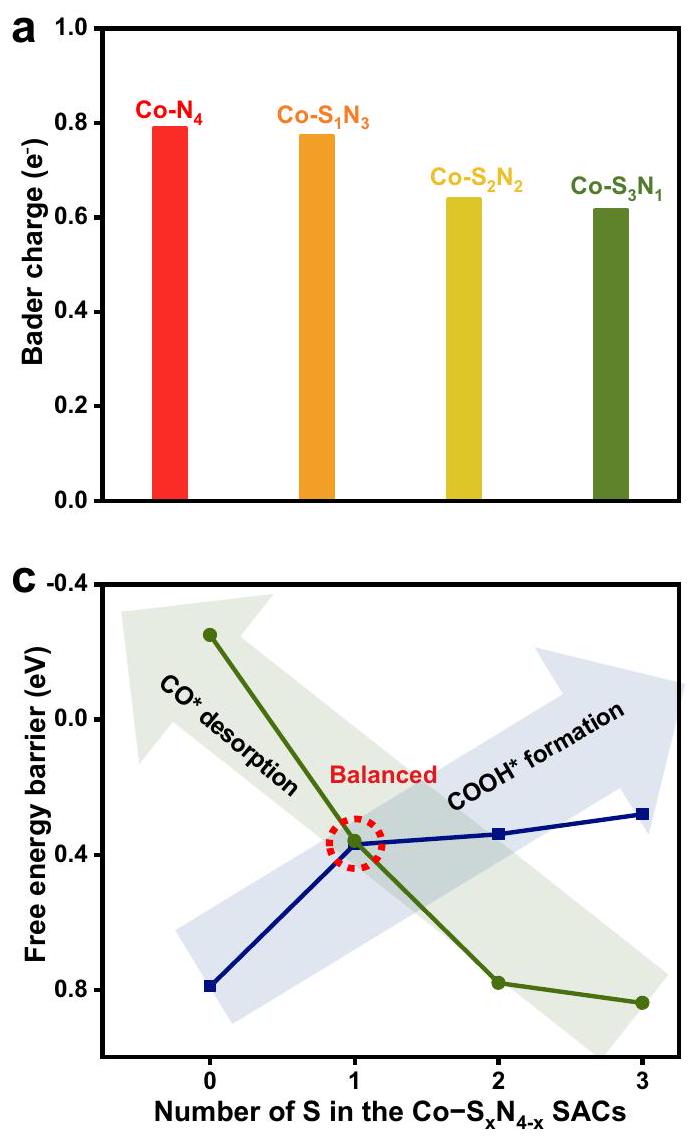
coordination environments of the SACs. The electronic tuning effect is found on the with different coordination numbers, demonstrating the strong sensitivity on the local coordination environments. The valence states of Co in these SACs decrease gradually when the amount of S increases, because of the lower electronegativity of the S than N . A sharp pre-edge peak around 7715.4 eV is observed for the CoPc with pyridinic moieties in a square planar configuration. However, this peak does not appear for the SACs, suggesting the adsorption of additional molecules on the Co sites in the SACs. Co complexes have been reported as adsorption materials . Because the synthesized SACs were stored in air, may adsorb on the Co sites.
The fine local coordination environments were investigated by the FT-EXAFS (Fig. 2b). For the sample, only one peak at is observed, demonstrating the single-atom structure of Co in . This peak is close to the Co-N scattering ( ) observed for the CoPc. After introducing S, a peak at about emerges, and its intensity increases with the S amount increase. This peak can be assigned to the scattering by the reference of CoS . Because of the larger size of S than N , the scattering is larger than that of scattering. No other peaks, such as configuration, can be observed, confirming the Co single-atom structure of the series. We further extracted the structural parameters from the Co K-edge EXAFS fittings. Considering the differences of XANES and EXAFS between the and the standard spectra ( CoPc ), one molecule was allowed to adsorb on the Co atom in perpendicular to the plane . Thus, the (from the Co coordination with the substrate) and (from the Co coordination with adsorbed ) scattering paths were used in the fitting. The fitting results are shown in Fig. 2c-f and Supplementary Figs. 4-8, and the
structural parameters are summarized in Supplementary Table 4. The coordination number decrease with the coordination number increase, demonstrating the replacement of N to S . The atomic structure models of SACs were constructed based on the fitting results and shown in the inset of Fig. 2c-f. Furthermore, we also simulated their XANES spectra that matched the experimental results well (Supplementary Fig. 9), demonstrating the successful synthesis of the series of local coordination environment fine-tuned , and SACs. These results show that our thermal replacement approach can be adopted to tune the local coordination environment of the SACs.
The chemical environments of the SACs were examined by the X-ray photoelectron spectroscopy (XPS) as well. From XPS spectra, we found that the S atoms were successfully incorporated into the carbon substrate by this thermal replacement strategy. The mainly identifies the existence of and bonds in , and , indicating the partial substitution of neighbouring N with S atoms (Supplementary Fig. 10a-c). The S atoms were mainly substituted for pyridinic-N, demonstrated by C and N 1s XPS results (Supplementary Figs. 11, 12). Compared with , the contents of pyridinic- N and in , and clearly reduce with the substitution of S atoms (Supplementary Table 5). We also studied the S substitution process on the carbon substrate. When pyrolysis of graphite with the S source, no S could be detected in products from the XPS (Supplementary Fig. 13). It suggests that the S cannot be doped into the highly graphited carbon substrate. When using the nitrogen-doped carbon as the substrate, the peaks were observed in the XPS pattern, demonstrating the replaced the sites in the pyrolysis processes. The Raman spectra of confirm the formation of disordered and graphitic carbon (Supplementary
Fig. 1 | The synthesis and electromicroscopy of the Co- SACs. a Schematic preparation procedure of SACs. The TEM images, AC HAADF-STEM images and the EDS mappings of , and .
Fig. 2 | The local coordination environments of the Co-Sx SACs. a XANES spectra of the SACs. The inset is the enlarged area of the absorptionedge. FT-EXAFS spectra of the SACs. FT-EXAFS fittings at R space of
, and . The inset is the model for the metal sites of the corresponding SACs. Co (yellow), S (cyan), N (blue), O (red), C (grey).
Fig. 14), which is in-line with the previously reported carbonbased SACs.

performance of the SACs

We evaluated the performance of , and SACs in H-cell filled with -saturated (Supplementary Fig. 15) to study the influence by the local coordination environment. Figure 3a shows the linear sweep voltammetry (LSV) curves. All potentials were – corrected, in which the solution resistance ( ) was measured by electrochemical impedance spectroscopy and shown in Supplementary Fig. 16. A cathodic current was observed when scanned to lower potential, demonstrating the occurrence of reduction reactions. By using with different S and N amounts, the current density significantly changed, implying the performance is strongly correlated to the local coordination environment. The has a current density of at -0.6 V (vs. RHE, the same hereafter), followed by , and . The also shows the lowest onset potential of about -0.3 V relative to those counterparts. Moreover, when the catalysts were measured in Ar-saturated electrolyte, significantly reduced current density was observed, implying the cathodic current mainly from the (Supplementary Fig. 17).
We further detected the gaseous products of the reaction by online gas chromatography (GC, Supplementary Fig. 18) and NMR spectra (Supplementary Fig. 19), in which only gaseous products and CO were observed rather than other liquid products. To confirm the origin of the CO , an isotopic feeding experiment was formed (Supplementary Fig. 20). The mass spectrum shows the peaks at 29 and assigned to the product and feedstock respectively, substantiating that the CO product attributed to rather than side reactions such as the decomposition of the catalysts. The Faradaic efficiencies of were calculated based on GC results and shown in Fig. 3b. Additionally, the were also calculated and
displayed in Supplementary Fig. 21. The maximum are , , and for and SACs, respectively. To understand the intrinsic activity of the SACs, the electrochemical surface areas (ECSAs) of the catalysts were measured from the double layer capacitance (Supplementary Figs. 22 and for , and SACs, respectively) and the ECSA normalized CO partial current densities ( ) were given in Fig. 3c. The different implies the different activity of the catalysts, which were controlled by the local coordination environment of the SACs. At -0.62 V , the shows the highest of , which is and 5.4 -fold to those for , and , respectively. The -doped carbon substrates might contribute to the activity as well. In order to investigate the influence of the substrates, we synthesized four control samples (CN-800, CNS-900, CNS-1000, and CNS-1100) using the similar preparation procedures for SACs but without adding Co sources, and then tested their performance. As shown in Supplementary Fig. 24, the N, S-doped carbon substrates showed much lower performances compared with their counterpart SACs, indicated by their lower current density, lower and thus much lower It suggested that the activities were mainly from the single atomic Co sites (Supplementary Table 6). And thus, the TOF of the SACs was calculated based on the Co sites. To eliminate the activity contribution from the substrate, we subtracted the , substrate from the total , and the detailed calculation method was shown in the Method part. The TOF at an overpotential of 410 mV were , and for , and SACs, respectively (Fig. 3d). It is further demonstrated that the exhibited the highest intrinsic activity of the Co active site for , and also surpassed the most reported Co-based atomic catalysts . In short, inspired by the continuous substitution between the neighboring N and S atoms, a series of single atom present a
Fig. 3 | performance of the . a Polarization curves of the catalysts tested in -saturated electrolyte. The Faradaic efficiencies of measured by GC. c The corresponding the SACs, the electrochemical surface area (ECSA) normalized . d The turnover frequency

(TOF) compared with the previously reported
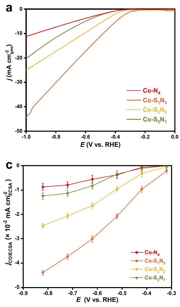
 catalysts. The reference data were obtained from refs. 44-52. Error bars are s.d. of at least three sets of experimental repeats.
volcano-type activity trend, and the structure locates at the apex of the volcano with the optimal catalytic properties. In terms of the best activity and selectivity, the overcomes most of the reported RR SACs (Supplementary Table 7).
Furthermore, the also displays excellent stability toward , which still retains of current density and of after 20 h of continuous electrolysis (Supplementary Fig. 25). After the durability test, we characterized the catalyst by HAADF-STEM, AC HAADF-STEM images, EDS mappings, XRD pattern as well as EXAFS (Supplementary Figs. 26-29). All the results show that the morphology and coordination structures of the catalyst were well maintained.
In order to evaluate the practical application of the SACs under high current density conditions, a conventional flow cell using gas diffusion electrodes was employed (Supplementary Fig. 30). Supplementary Fig. 31a shows the polarization curve obtained using the flow cell setup. Beneficial from the improved mass transfer, a much higher current density was achieved. For example, it reached a high current density of at -0.83 V . It showed outstanding CO selectivity with the above in a wide current density region from -50 to (Supplementary Fig. 31b). The SAC showed good durability in the 50 h of chronoamperometry at -0.76 V (Supplementary Fig. 31c), indicating by the slow current decay rate. The current density was at the initial and after 50 h of electrolysis, preserved at . The was measured ever 4 h
of electrolysis, and maintained at a high level of throughout the 50 h of the stability test.

The coordination-performance relationship

The above results demonstrate the significantly different performance of the SACs, implying the performance was determined by the local coordination environment of the SACs. We firstly examined that Co centers work as the active sites for . The foregoing results demonstrated that the , 1, 2, 3) SACs had much higher performance than their N,S doped carbon counterparts, suggesting the important role of the Co sites. A poisoning experiment was also carried out by introducing , and a distinct depression of current density was observed (Supplementary Fig. 32). No convincing poisoning effect was observed on the carbon substrate counterparts (Supplementary Fig. 33), further implying the Co centers as active sites.
We also performed in-situ XAS experiments to elucidate the local geometry of during the process (Supplementary Fig. 34). The Co XANES spectra show that the near-edge absorption position shifts to lower energy and the white peak intensity decreases when the applied potentials changed from open circuit to -0.5 V and then to -0.6 V , indicating that gradual decrease of the valence state of Co is accompanied by the . The FT-EXAFS spectra reveal that the peak shifts to a little longer length while applying potentials to the electrode, indicating the redistribution of electrons at the atomic interface, but still maintaining the initial
Fig. 4 | Theoretical calculated energy diagram of the SACs. a Bader charge analyses. Calculated potential free energy diagrams for to CO on the SACs. c Evolution of free energy of the formation and CO *
desorption steps associated with the S numbers in the SACs. Trend of the calculated limiting potentials and measured correlated with the number of S in the SACs.
moiety. The extracted EXAFS fitting results are shown in Supplementary Figs. 35-37 and Supplementary Table 8. These results suggested that the Co center with a certain local coordination environment worked as the active sites for the process.
To understand how the local coordination environment affects the Co center, and thus affects the performance of the Co SACs, DFT calculations were carried out to investigate the detailed reaction mechanism. From the ex-situ XAS measurements, an adsorbed oxygen was found on the Co sites. The Co-N-C materials were exhibited as good oxygen reduction reaction catalysts . At the potential occurred, the adsorbed oxygen should be reduced. Thus, we considered the SACs without an adsorbed oxygen at the condition. The employed adsorption configuration of each species on the catalysts are shown in Supplementary Figs. 38-41. The charge density and Bader charge analysis were firstly examined. The charges on Co centers continuously decrease with the increase of coordination number, indicating the fine-tuning of the local coordination environment to the electronic structure of the metal centers in the SACs (Fig. 4a). These calculation results are consistent with the XANES observations.
The binding energies of the intermediates were calculated next. The couples with a proton and transfers an electron to form the first intermediates of , and then couples with another proton and transfer another electron to form adsorbed and release a . Finally, the CO * desorbed to generate the CO products . The potential free energy diagrams, including the key intermediates and , were calculated and shown in Fig. 4 b . It demonstrates that the binding energy of the and intermediates strongly depends on the local coordination environment of the conters.
With increasing the coordination number of , stronger adsorption for both and was exhibited. The stronger binding energy to the intermediates promotes the adsorption steps, but hinders the desorption steps. There are mainly two endothermic steps in the reaction processes, i.e., the formation of the and the desorption of *CO. The energy barriers of these two steps are correlated to the binding energy of the and , respectively. Figure 4 c summarizes the energy barriers of the two steps on each SAC. With the increase of the coordination number of Co-S in the SACs, the energy barrier for the continuously decreases, and the desorption of continuously increases. For , it binds COOH too weakly. Thus, the formation of the is the potential-limiting step for the on . By substitution of N with S , the adsorption of is enhanced, thus lowering the energy barrier required for the first step. However, the adsorption of strengthens accordingly, making the desorption of CO * difficult. For and , the CO * desorption turns into the potential-limiting steps. Considering both factors, a volcano-shaped activity trend is observed and illustrated in Fig. 4d. The theoretical limiting potentials are 0.79, 0.37, 0.78, and 0.84 eV on and SACs, respectively. This trend is consistent with the measured activity. Due to the volcano shape activity trend, it requires fine-tuning the local coordination environment of the catalysts in order to reach the apex of the volcano. With only one N substituted by S , the has a lowered energy barrier for formation and not too strong CO adsorption, showing the optimized reaction pathway to give the highest performance.
Although the major trend of the calculation results to the experimental results matched well, we note there is a slight
inconsistency. Based on the calculation, the should have slightly higher activity than and , but the experimental results are opposed. The previous results demonstrated that the porosity of the SACs increases with the increase of the S content. The porous structure and large BET area ensure effective mass transfer, which is beneficial for the process. Co- has lower porosity than and , which declined its performance. It demonstrated that other than the major influence of the local coordination environment, the porosity influences the performance of the SACs as well.
The binding to H , which is important for the competitive HER, is also adjusted by the local coordination environment of the SACs. With increasing the S coordination number, the stronger adsorption of was exhibited, similar to the circumstances for the intermediates. The limiting potential differences between and HER (i.e., , where ) determine the selectivity of a catalyst in , and the values for the series of Co SACs are shown in Supplementary Fig. 42. Apparently, the Co catalyst has the most positive value, indicating the highest selectivity for CO production.
In conclusion, we developed a thermal replacement strategy to synthesize SACs with precisely controlled central Co metal local coordination environments. Systematically tuned SACs, i.e., , and , were successfully synthesized, and the coordination- performance relationship was investigated. Beneficial from the fine-tuned local coordination environments, the binding strength to the intermediates (* COOH and * CO ) was continuously weakened with the increase of the coordination number of Co-S. A volcano-type activity trend was observed. The SACs located at the apex of the volcano with the optimized binding to the and , and exhibited high activity and selectivity towards to CO . This tailoring offers a promising approach to design and synthesize highly active electrocatalysts.

Methods

Chemicals

Cobalt (II) acetylacetone ( ), potassium bicarbonate, Nafion D-521 dispersion ( in water and 1-propanol), 2-methylimidazole, thiophene were purchased from Alfa Aesar. Zinc nitrate hexahydrate (98%), N, N-dimethylformamide (DMF), methanol, and ethanol were obtained from Sinopharm Chemical. Nafion 117 membrane was purchased from Dupont. All the chemicals and gases were analytical grade and used without further purification. Ultrapure water was used throughout the experiment.
Synthesis of the single-atom catalysts The Co-ZIF-8 was firstly synthesized. 1.07 g of and 0.12 g of were added into 30 ml of DMF and methanol mixture solution (volume ratio ) and stirred for 30 min . After that, 1.16 g of 2-methylimidazole dissolved in 30 ml of DMF and methanol mixture was added into the above solution and constantly stirred for 12 h . The obtained Co-ZIF-8 powders were washed with methanol several times and dried at in a vacuum oven overnight.
The Co-ZIF-8 powder was directly annealed at under an Ar atmosphere for 3 h to obtain . For the synthesis of , , and SACs, 200 mg of Co -ZIF- 8 powders and 0.5 ml of thiophene were added to 20 ml ethanol and sonicated for 2 h . The suspension was stirred for another 5 h at room temperature, followed by centrifuging and drying in a vacuum oven to get the S-doped precursor. Then it was pyrolyzed at 900,1000 , and with a heating rate of under an Ar atmosphere maintained for 3 h to obtain , and SACs, respectively.

Physical characterizations

The morphology of the catalysts was monitored by transmission electron microscope (TEM, FEI Tecnai G2 F20 S-Twin) with an accelerating voltage of 200 kV as well as the field-emission scanning electron microscope (FE-SEM, JEORJSM-6700F). The HAADF-STEM images were measured by JEOL JEM-ARM200F, which worked at an accelerating voltage of 300 kV . The atomic structure of the and reference catalysts was characterized using a JEOL ARM-200CF transmission electron microscope operated at 200 keV and equipped with double spherical aberration (Cs) correctors. The crystal phases were characterized by powder X-ray diffraction (XRD, Rigaku D/max radiation, ). The X-ray photoelectron spectroscopy (XPS) measurements were performed with a Perkin Elmer Physics PHI 5300 spectrometer using Al K nonmonochromatic radiation. The adsorption/desorption curves were tested at 77 K using a Micromeritics ASAP 2020 surface area analyzer. The metal content was monitored by inductively coupled plasma optical emission spectrometry (ICP-OES), which was carried out on Thermo Fisher IRIS Intrepid II. The light elements ( , and S ) contents of the SACs were measured by an elemental analyzer (Elementar UNICUBE).

XAFS measurements

The Co K-edge X-ray absorption measurements were conducted at the BL14W1 station within the Shanghai Synchrotron Radiation Facility (SSRF), which operates at 3.5 GeV with a maximum current of 250 mA . The X-ray radiation was monochromatized using a Si (111) double-crystal monochromator. The intensity of the incident X-ray was monitored using an -filled ion chamber ( ) positioned in front of the sample. Solid samples were placed in an aluminum sample holder sealed with Kapton tape. The data were acquired as fluorescence excitation spectra using a Lytle detector. Energy calibration was performed using the first peak maximum of the first derivative of a Co foil, which was positioned between two -filled ionization chambers ( and ) after the sample. Reference spectra were recorded in transmission mode using an -filled ionization chamber. All measurements were conducted at room temperature.
In-situ electrochemical XAS measurements were conducted using a computer-controlled organic glass electrochemical cell. The working electrode utilized a catalyst-modified carbon paper, while the counter electrode was Pt wire and the reference electrode was saturated). The carbon paper coated with was placed in contact with a copper slip, with the layer facing inward, and then the cell was filled with solution. The solutions were not agitated during the electrochemical experiment. The in-situ cell was connected to an electrochemical station using a copper tape slip protruding from the side of the working cell. A glass cap, equipped with an electrode, was used to cover the cell and maintain an appropriate distance between the working and reference electrodes for all experiments. XAFS spectra were recorded under various conditions on the electrode.
The acquired EXAFS data were processed according to the standard procedures using the ATHENA module implemented in the IFEFFIT software packages. The EXAFS spectra were obtained by subtracting the post-edge background from the overall absorption and then normalizing with respect to the edge-jump step. Subsequently, the data of were Fourier transformed to real ( ) space using a hanning windows ( ) to separate the EXAFS contributions from different coordination shells. To obtain the quantitative structural parameters around central atoms, least-squares curve parameter fitting was performed using the ARTEMIS module of IFEFFIT software packages .
The following EXAFS equation was employed:
is the amplitude reduction factor, is the effective curvedwave backscattering amplitude, is the number of neighbors in the atomic shell, is the distance between the X-ray absorbing central atom and the atoms in the atomic shell (backscatterer), is the mean free path in is the phase shift (including the phase shift for each shell and the total central atom phase shift), is the Debye-Waller parameter of the atomic shell (variation of distances around the average ). The functions and were calculated with the ab initio code FEFF8.2. The coordination numbers of model samples were fixed as the nominal values. The obtained was fixed in the subsequent fitting. While the internal atomic distances , Debye-Waller factor , and the edge-energy shift were allowed to run freely.
The fitting parameters were listed in Supplementary Note 1.

Electrochemical measurements for

The experiments were performed on a CHI 660 e electrochemical workstation with an H-type cell filled with electrolyte. The Pt wire was used as the counter electrode and (saturated KCl ) as the reference electrode. To make the working electrode, 5 mg of as-synthesized series SACs and of Nafion solution were introduced into a mixture containing of water and of isopropyl alcohol. The resulting mixture was subjected to sonication for 3 h . The working electrode was prepared by drop casting the ink on carbon paper (HCP120, ), and the total loading amount of catalyst was controlled as . Nafion 117 membrane (the membrane size was , and effective area was circular with a diameter of 1.5 cm ) separated the cathodic chamber and anodic before adding electrolyte. A total volume of 30 mL of 0.5 M solution was poured into the anode and cathode chambers, and further bubbled by Ar for 30 min and then switched to . The polarization curves were conducted at a scan rate of with continuous bubbling of at a flow rate of 15 sccm . All the potential was reported versus the reversible hydrogen electrode (RHE) and corrected by of compensation. The solution resistance was measured by electrochemical impedance spectroscopy (EIS) across frequencies ranging from 0.1 Hz to 100 kHz . The gas products were checked via the Shimazu 2010 plus gas chromatography (GC), which was equipped with a BID detector and ShinCarbon ST 100/120 packed column. The liquid products were checked by the NMR spectra that were collected on a Bruker AV 400 MHz NMR spectrometer using residue solvent peaks as an internal standard ( NMR: at 4.69 ppm)
A custom-built electrochemical cell with three compartments (gas, cathodic, and anodic chambers) was employed for threeelectrode flow cell tests. The gas chamber thickness was 2 cm , and the anode and cathode liquid chamber have a thickness of 1 cm . A proton exchange membrane (Nafion 117) was placed between the cathodic and anodic chambers of the flow cell. The effective electrode area was , resulting in an active area of . In the flow cell test, the working electrode (cathode) utilized catalyst sprayed on GDL ( 28 BC , Sinero Store) with a loading of , while the counter electrode (anode) employed (Sinero Store) sprayed on GDL (28 BC, Sinero Store) with a loading of . The cathode side was supplied with electrolyte ( ) using a syringe pump (PHD 2000, Harvard Apparatus) at a constant flow rate of 10 sccm , while high purity gas was introduced at a rate of 50 sccm behind the cathode GDL. An Ag/AgCl (saturated KCl) reference electrode was utilized, and the potential was corrected by 100% of compensation.
The Faradaic efficiencies of the gas products were calculated by using the concentrations detected by the online GC as follows:
where is the flow rate of is the measured concentration of product in a 1 mL sample loop based on the calibration of the GC with a standard gas, is the number of electrons, F is the Faraday’s constant ( ), is the recorded current. The input flow rate was used for gaseous product FE calculations. It was assumed that the input flow rate was uniform across all currents and the cathode chamber sealed tightly.
Turnover frequency (TOF) for the to CO was evaluated as follows:
where is the corrected CO partial current for the metal sites, which is subtracted the CO partial current of the doped carbon substrate counterpart from the CO partial current of is the Faraday’s constant ( ), is the number of electrons, is the catalyst mass in the electrode, is Co loading in the catalyst, and is the atomic mass of .
The ECSAs was defined as the electrochemically active area of an electrode with of geometric area. And the ECSA was calculated by the equation as follow:
where the is the specific capacitance of flat electrode, is the geometric area of the electrode . We assumed the are the same for the and took the value of as suggested for the carbon materials based in literature .

Calculation details

The Vienna Ab Initio Simulation Package (VASP) was used to perform all the DFT simulations and the electron ion interaction was described with the projector augmented wave (PAW) method . The electron exchange and correlation energy was solved by using the revised Perdew-Burke-Ernzerhof (RPBE) exchange-correlation functional within the generalized gradient approximation . An energy cutoff of 400 eV and a second-order Methfessel-Paxton electron smearing with were used to guarantee the accuracy. The convergences criteria for energy and force are set to be and , respectively. A vacuum layer of was set between the periodically repeating slabs. Spin polarization was included throughout all the calculations.
The catalyst was modeled by a supercell of graphene doped with nitrogen and Co atoms, where Co coordinated with four neighboring N atoms as shown in Supplementary Fig. 38. Because of the high N contents, the configurations with an additional N to replace a carbon atom in the substrate were employed. As comparisons, the and catalysts were also modeled by a supercell with the four neighbor N atoms replaces by one, two and three S atoms as shown in Supplementary Figs. 39-41. The atomic coordinates were upload as txt files as Supplementary Data files. The Monkhorst-Pack grid K-points was used to sample the Brillouin zone for all four catalysts. The most stable adsorption configurations of and H species on the and catalysts were also given in Supplementary Figs. 38-41. The free energies of all the reaction mechanisms in this work were
calculated with computational hydrogen electrode (CHE) model as developed by Norskov group .

Data availability

All data in the article and supplementary information are available from the corresponding authors upon request.

References

  1. Guo, W., Wang, Z., Wang, X. & Wu, Y. General design concept for single-atom catalysts toward heterogeneous catalysis. Adv. Mater. 33, 2004287 (2021).
  2. Fei, H. et al. Single atom electrocatalysts supported on graphene or graphene-like carbons. Chem. Soc. Rev. 48, 5207-5241 (2019).
  3. Zhang, N. et al. Single-atom site catalysts for environmental catalysis. Nano Res. 13, 3165-3182 (2020).
  4. Jin, S., Hao, Z., Zhang, K., Yan, Z. & Chen, J. Advances and challenges for the electrochemical reduction of to CO : from fundamentals to industrialization. Angew. Chem. Int. Ed. 60, 20627-20648 (2021).
  5. Gawande, M. B., Fornasiero, P. & Zbořil, R. Carbon-based singleatom catalysts for advanced applications. ACS Catal. 10, 2231-2259 (2020).
  6. Li, M. et al. Heterogeneous single-atom catalysts for electrochemical reduction reaction. Adv. Mater. 32, 2001848 (2020).
  7. Han, S. G., Ma, D. D. & Zhu, Q. L. Atomically structural regulations of carbon-based single-atom catalysts for electrochemical reduction. Small Methods 5, 2100102 (2021).
  8. Zhu, S. et al. Recent advances in catalyst structure and composition engineering strategies for regulating electrochemical reduction. Adv. Mater. 33, e2005484 (2021).
  9. Wen, C. et al. Highly ethylene-selective electrocatalytic reduction enabled by isolated Cu@SMotifs in metal-organic framework based precatalysts. Angew. Chem. Int. Ed. 61, e202111700 (2022).
  10. Wang, J. et al. Linkage effect in the heterogenization of cobalt complexes by doped graphene for electrocatalytic reduction. Angew. Chem. Int. Ed. 58, 13532-13539 (2019).
  11. Wang, D. et al. Palladium-catalyzed silacyclization of (hetero)arenes with a tetrasilane reagent through twofold C-H activation. Angew. Chem. Int. Ed. 60, 7066-7071 (2021).
  12. Cai, Y. et al. Insights on forming N,O-coordinated Cu single-atom catalysts for electrochemical reduction to methane. Nat. Commun. 12, 586 (2021).
  13. Feng, J. et al. A single-atom catalyst embedded in graphitic carbon nitride for efficient electroreduction. Nat. Commun. 11, 4341 (2020).
  14. Zheng, T., Jiang, K. & Wang, H. Recent advances in electrochemical -to-CO conversion on heterogeneous catalysts. Adv. Mater. 30, 1802066 (2018).
  15. Zhao, K. et al. Selective electroreduction of to acetone by single copper atoms anchored on N-doped porous carbon. Nat. Commun. 11, 2455 (2020).
  16. Tang, C. et al. Coordination tunes selectivity: Two-electron oxygen reduction on high-loading molybdenum single-atom catalysts. Angew. Chem. Int. Ed. 59, 9171-9176 (2020).
  17. Ren, Y. et al. Unraveling the coordination structure-performance relationship in single-atom catalyst. Nat. Commun. 10, 4500 (2019).
  18. Wang, G. et al. Photoinduction of Cu single atoms decorated on UiO-66- for enhanced photocatalytic reduction of to liquid fuels. J. Am. Chem. Soc. 142, 19339-19345 (2020).
  19. Zhang, H. et al. Dynamic traction of lattice-confined platinum atoms into mesoporous carbon matrix for hydrogen evolution reaction. Sci. Adv. 4, eaao6657 (2018).
  20. Zhang, H., Liu, G., Shi, L. & Ye, J. Single-atom catalysts: emerging multifunctional materials in heterogeneous catalysis. Adv. Energy Mater. 8, 1701343 (2017).
  21. Xu, H., Cheng, D., Cao, D. & Zeng, X. C. A universal principle for a rational design of single-atom electrocatalysts. Nat. Catal. 1, 339-348 (2018).
  22. Liu, J. Catalysis by supported single metal atoms. ACS Catal. 7, 34-59 (2016).
  23. Seh, Z. W. et al. Combining theory and experiment in electrocatalysis: Insights into materials design. Science 355, 146 (2017).
  24. Liu, P. & Zheng, N. Coordination chemistry of atomically dispersed catalysts. Natl Sci. Rev. 5, 636-638 (2018).
  25. Long, X. et al. Graphitic phosphorus coordinated single Fe atoms for hydrogenative transformations. Nat. Commun. 11, 4074 (2020).
  26. Shen, H. et al. Synergistic effects between atomically dispersed Fe-N-C and C-S-C for the oxygen reduction reaction in acidic media. Angew. Chem. Int. Ed. 56, 13800-13804 (2017).
  27. Haile, A. S., Hansen, H. A., Yohannes, W. & Mekonnen, Y. S. The role of nitrogen and sulfur dual coordination of cobalt in single atom catalysts in the oxygen reduction reaction. Sustain. Energy Fuels 6, 179-187 (2022).
  28. Wang, X. et al. Regulation of coordination number over single Co sites: triggering the efficient electroreduction of . Angew. Chem. Int. Ed. 57, 1944-1948 (2018).
  29. Rong, X., Wang, H. J., Lu, X. L., Si, R. & Lu, T. B. Controlled synthesis of a vacancy-defect single-atom catalyst for boosting electroreduction. Angew. Chem. Int. Ed. 59, 1961-1965 (2020).
  30. Hou, Y. et al. Atomically dispersed nickel-nitrogen-sulfur species anchored on porous carbon nanosheets for efficient water oxidation. Nat. Commun. 10, 1392 (2019).
  31. Wan, J. et al. In situ phosphatizing of triphenylphosphine encapsulated within metal-organic frameworks to design atomic interfacial structure for promoting catalytic performance. J. Am. Chem. Soc. 142, 8431-8439 (2020).
  32. Cheng, Q. et al. Carbon-defect-driven electroless deposition of Pt atomic clusters for highly efficient hydrogen evolution. J. Am. Chem. Soc. 142, 5594-5601 (2020).
  33. Yan, C. et al. Coordinatively unsaturated nickel-nitrogen sites towards selective and high-rate electroreduction. Energy Environ. Sci. 11, 1204-1210 (2018).
  34. Zhang, L. et al. Atomic layer deposited Pt-Ru dual-metal dimers and identifying their active sites for hydrogen evolution reaction. Nat. Commun. 10, 4936 (2019).
  35. Hai, X. et al. Engineering local and global structures of single co atoms for a superior oxygen reduction reaction. ACS Catal. 10, 5862-5870 (2020).
  36. Tong, M. et al. Operando cooperated catalytic mechanism of atomically dispersed and for promoting oxygen reduction reaction. Angew. Chem. Int. Ed. 60, 14005-14012 (2021).
  37. Yang, Q. et al. Understanding the activity of in atomic metal catalysts for oxygen reduction catalysis. Angew. Chem. Int. Ed. 59, 6122-6127 (2020).
  38. Gong, Y. N. et al. Regulating the coordination environment of MOFtemplated single-atom nickel electrocatalysts for boosting reduction. Angew. Chem. Int. Ed. 59, 2705-2709 (2020).
  39. Hu, L. et al. Metal-triazolate-framework-derived singleatom catalysts with hierarchical porosity for the oxygen reduction reaction. Angew. Chem. Int. Ed. 60, 27324-27329 (2021).
  40. Jiao, L. et al. From metal-organic frameworks to single-atom Fe implanted N -doped porous carbons: efficient oxygen reduction in both alkaline and acidic media. Angew. Chem. Int. Ed. 57, 8525-8529 (2018).
  41. Johnson, C . et al. Near stoichiometric binding on metal centers in Co(salen) nanoparticles. AIChE J. 55, 1040-1045 (2009).
  42. Chen, Y. et al. Isolated single iron atoms anchored on N-Doped porous carbon as an efficient electrocatalyst for the oxygen reduction reaction. Angew. Chem. Int. Ed. 56, 6937-6941 (2017).
  43. Fei, H. et al. General synthesis and definitive structural identification of single-atom catalysts with tunable electrocatalytic activities. Nat. Catal. 1, 63-72 (2018).
  44. Yang, H. B. et al. Atomically dispersed Ni(i) as the active site for electrochemical reduction. Nat. Energy 3, 140-147 (2018).
  45. Lin, S. et al. Covalent organic frameworks comprising cobalt porphyrins for catalytic reduction in water. Science 349, 1208-1213 (2015).
  46. Zhu, M. et al. Covalently grafting cobalt porphyrin onto carbon nanotubes for efficient electroreduction. Angew. Chem. Int. Ed. 58, 6595-6599 (2019).
  47. Pan, Y . et al. Design of single-atom catalytic site: A robust electrocatalyst for reduction with nearly 100% CO selectivity and remarkable stability. J. Am. Chem. Soc. 140, 4218-4221 (2018).
  48. Gu, J., Hsu, C.-S., Bai, L., Chen, H. M. & Hu, X. Atomically dispersed sites catalyze efficient electroreduction to co. Science 364, 1091-1094 (2019).
  49. Zhao, C. et al. lonic exchange of metal-organic frameworks to access single nickel sites for efficient electroreduction of . J. Am. Chem. Soc. 139, 8078-8081 (2017).
  50. Kornienko, N. et al. Metal-organic frameworks for electrocatalytic reduction of carbon dioxide. J. Am. Chem. Soc. 137, 14129-14135 (2015).
  51. Morlanés, N., Takanabe, K. & Rodionov, V. Simultaneous reduction of and splitting of by a single immobilized cobalt phthalocyanine electrocatalyst. ACS Catal. 6, 3092-3095 (2016).
  52. Han, N. et al. Supported cobalt polyphthalocyanine for highperformance electrocatalytic reduction. Chem 3, 652-664 (2017).
  53. Zhang, B. et al. Manganese acting as a high-performance heterogeneous electrocatalyst in carbon dioxide reduction. Nat. Commun. 10, 2980 (2019).
  54. Cheng, W., Su, H. & Liu, Q. Tracking the oxygen dynamics of solidliquid electrochemical interfaces by correlative in situ synchrotron spectroscopies. Acc. Chem. Res. 55, 1949-1959 (2022).
  55. Yin, P. et al. Single cobalt atoms with precise N-coordination as superior oxygen reduction reaction catalysts. Angew. Chem. Int. Ed. 55, 10800-10805 (2016).
  56. Kortlever, R., Shen, J., Schouten, K. J., Calle-Vallejo, F. & Koper, M. T. Catalysts and reaction pathways for the electrochemical reduction of carbon dioxide. J. Phys. Chem. Lett. 6, 4073-4082 (2015).
  57. Shi, C., Hansen, H. A., Lausche, A. C. & Norskov, J. K. Trends in electrochemical reduction activity for open and close-packed metal surfaces. Phys. Chem. Chem. Phys. 16, 4720-4727 (2014).
  58. Kim, D. et al. Electrochemical activation of through atomic ordering transformations of AuCu nanoparticles. J. Am. Chem. Soc. 139, 8329-8336 (2017).
  59. Ren, W. et al. Isolated diatomic Ni-Fe metal-nitrogen sites for synergistic electroreduction of . Angew. Chem. Int. Ed. 58, 6972-6976 (2019).
  60. Qiao, B. et al. Single-atom catalysis of CO oxidation using . Nat. Chem. 3, 634-641 (2011).
  61. Zitolo, A. et al. Identification of catalytic sites for oxygen reduction in Iron- and Nitrogen-doped graphene materials. Nat. Mater. 14, 937-942 (2015).
  62. Briois, V. et al. Spectroscopie d’absorption des rayons X au seuil K : complexes moléculaires du cobalt. J. Chim. Phys. 86, 1623-1634 (1989).
  63. Liu, Y. et al. Determining the coordination environment and electronic structure of polymer-encapsulated cobalt phthalocyanine under electrocatalytic reduction conditions using in situ X-Ray absorption spectroscopy. Dalton Trans. 49, 16329-16339 (2020).
  64. Obreja, V. V. N. On the performance of supercapacitors with electrodes based on carbon nanotubes and carbon activated materiala review. Phys. E 40, 2596-2605 (2008).
  65. Kresse, G. & Furthmüller, J. Efficiency of ab-initio total energy calculations for metals and semiconductors using a plane-wave basis set. Comp. Mater. Sci. 6, 15-50 (1996).
  66. Kresse, G. & Furthmüller, J. Efficient iterative schemes for ab initio total-energy calculations using a plane-wave basis set. Phys. Rev. B. 54, 11169-11186 (1996).
  67. Blochl, P. E. Projector augmented-wave method. Phys. Rev. B 50, 17953-17979 (1994).
  68. Kresse, G. & Joubert, D. From ultrasoft pseudopotentials to the projector augmented-wave method. Phys. Rev. B 59, 1758-1775 (1999).
  69. Hammer, B., Hansen, L. B. & Nørskov, J. K. Improved adsorption energetics within density-functional theory using revised Perdew-Burke-Ernzerhof functionals. Phys. Rev. B 59, 7413-7421 (1999).
  70. Nørskov, J. K. et al. Origin of the overpotential for oxygen reduction at a fuel-cell cathode. J. Phys. Chem. B 108, 17886-17892 (2004).
  71. Peterson, A. A., Abild-Pedersen, F., Studt, F., Rossmeisl, J. & Nørskov, J. K. How copper catalyzes the electroreduction of carbon dioxide into hydrocarbon fuels. Energy Environ. Sci. 3, 1311-1315 (2010).

Acknowledgements

This work was supported by the National Natural Science Foundation of China (21971008 ZZ, 22375019 WC, 21971002 JM), Fundamental Research Funds for the Central Universities (buctrc201916, ZZ) and Beijing Institute of Technology Research Fund Program for Young Scholars (3090012221909, WC). The authors thank the 1W1B in the Beijing Synchrotron Radiation Facility (BSRF), BL14W1 in the Shanghai Synchrotron Radiation Facility (SSRF), BL10B and BL12B in the National Synchrotron Radiation Laboratory (NSRL) for help with characterizations.

Author contributions

Z.Z. and W.C. conceived the idea and designed the study. J.P. and H.S. carried out the sample synthesis and characterizations. F.Z. performed the electron microscopy characterizations. Z.C. and T.W. performed the DFT calculations. J.M. helped with data analysis. R.S., X.Z. and W.Z. helped with the electrochemical carbon dioxide performance test and analysis. D.Z., Y.W. and W.C. carried out the XANES characterizations and data analysis. Z.Z. and J.P. wrote the manuscript. All authors discussed the results and assisted with the manuscript preparation.

Competing interests

The authors declare no competing interests.

Additional information

Supplementary information The online version contains
supplementary material available at
https://doi.org/10.1038/s41467-023-44652-7.
Correspondence and requests for materials should be addressed to Tao Wang, Wenxing Chen or Zhongbin Zhuang.
Peer review information Nature Communications thanks Yedilfana Mekonnen, Samy Ould-Chikh and the other, anonymous, reviewer for their contribution to the peer review of this work.
Reprints and permissions information is available at http://www.nature.com/reprints
Publisher’s note Springer Nature remains neutral with regard to jurisdictional claims in published maps and institutional affiliations.
Open Access This article is licensed under a Creative Commons Attribution 4.0 International License, which permits use, sharing, adaptation, distribution and reproduction in any medium or format, as long as you give appropriate credit to the original author(s) and the source, provide a link to the Creative Commons licence, and indicate if changes were made. The images or other third party material in this article are included in the article’s Creative Commons licence, unless indicated otherwise in a credit line to the material. If material is not included in the article’s Creative Commons licence and your intended use is not permitted by statutory regulation or exceeds the permitted use, you will need to obtain permission directly from the copyright holder. To view a copy of this licence, visit http://creativecommons.org/ licenses/by/4.0/.
© The Author(s) 2024

  1. State Key Lab of Organic-Inorganic Composites and Beijing Advanced Innovation Center for Soft Matter Science and Engineering, Beijing University of Chemical Technology, Beijing 100029, China. Energy & Catalysis Center, School of Materials Science and Engineering, Beijing Institute of Technology, Beijing 100081, China. College of Chemistry and Materials Science, Anhui Normal University, Wuhu 241002, China. Center of Artificial Photosynthesis for Solar Fuels, School of Science, Westlake University, Hangzhou 310024, China. Shanghai Synchrotron Radiation Facilities, Shanghai Institute of Applied Physics, Chinese Academy of Science, Shanghai 201204, China. Analysis and Testing Center, Beijing Institute of Technology, Beijing Institute of Technology, Beijing 100081, China. Beijing Key Laboratory of Energy Environmental Catalysis, Beijing University of Chemical Technology, 100029 Beijing, China. These authors contributed equally: Jiajing Pei, Huishan Shang, Junjie Mao. e-mail: twang@westlake.edu.cn; wxchen@bit.edu.cn; zhuangzb@mail.buct.edu.cn