الاختزال المتسلسل للنترات وثاني أكسيد الكربون يمكّن من التخليق الكهربائي الانتقائي لليوريا Sequential co-reduction of nitrate and carbon dioxide enables selective urea electrosynthesis
على الرغم من الإنجازات الأخيرة في تخليق اليوريا الكهربائي من اختزال النيتروجين النفايات (مثل) و تظل انتقائية المنتج متوسطة إلى حد ما بسبب الطبيعة التنافسية للتفاعلات الاختزالية الموازية. هنا نبلغ عن تصميم محفز يوفر انتقائية عالية لليوريا من خلال الاختزال المتسلسلوفي مركز تحفيزي ديناميكي، الذي لا يخفف فقط من مشكلة المنافسة ولكن يسهل أيضًا الاقتران. نحن نوضح هذه الاستراتيجية على محفز كربوني مخدر بالنيتروجين، حيث يحدث تبديل تلقائي بين وتفعيل مسارات الاختزال يتم من خلال الهدرجة القابلة للعكس على مجموعات النيتروجين الوظيفية. معدل إنتاج عالي لليوريامع كفاءة فارادائية واعدة منتم الحصول على ذلك. هذه النتائج، التي تم تفسيرها من خلال تقنيات الطيفية في الموقع والحسابات النظرية، متجذرة في تطور المحفز الديناميكي المتضمن للبروتون الذي يخفف من الانخفاض المفرط للمواد المتفاعلة وبالتالي يقلل من تكوين المنتجات الجانبية.
لقد fueled الزيادة الأخيرة في الأدبيات المخصصة للتخليق الكهروكيميائي لليوريا بالحاجة الماسة لكل من الحفاظ على الطاقة وتثبيت للتخفيف من تغير المناخ. كواحد من أكثر الأسمدة النيتروجينية استخدامًايمكن تصنيع اليوريا على المستوى الصناعي من خلال التفاعلات المتتالية لـ و اليوريا، وكلاهما يتطلبان طاقة كبيرة وظروف قاسيةإنتاج اليوريا المدفوع بالكهرباء المتجددة باستخدام أنواع النيتروجين (مثل،النترات، النيتريت، NO” وكمواد خاميقدم بديلاً واعدًا للطريق التقليدي (الشكل التوضيحي التكميلي 1)، ولكن لا تزال هناك نقص في الدراسات التي تجسد حلولاً عملية لتخليق اليوريا على نطاق واسع.التحدي الأكثر رعبًا هو اكتشاف محفز انتقائي فعالالترابط بعد الهدرجة المعتدلة للمواد المتفاعلة، مع تثبيط تحويلها إلى منتجات جانبية مثلو شركة . فيما يتعلق بالهدرجة و عملية الاقتران، النيتروجين الثابت أكثر جاذبية منكمصدر للنيتروجين، حيثالجزيء لديه طاقة تفكك عالية للغاية للرابطة الثلاثية ) وذوبان أقل في الماء . على الرغم من التفاعل المباشر بين الممتزاتواقترح أن CO، ستمنع القيود الحركية تحقيق معدل عائد مرضٍ من اليوريا. على النقيض من ذلك، فإن الاختزال الكهربائي المشترك للنترات) و أسهل بكثير لتحقيقالذي، عند توجيهه نحو تكوين اليوريا، يحمل آفاقًا مثيرة للتصنيع نظرًا للوصول السهل إلىمن مياه الصرف الصناعي والصرف الصحي المنزلي (الشكل التوضيحي 2). المشكلة، مع ذلك، هي أن عمليات الهدرجة لـوفي الواقع تتنافس مع بعضها البعض، ناهيك عن أن كلا العمليتين يجب أن تحدثا في نفس الموقع تقريبًا للسماح بسهولةاقتران. في الواقع، مع وجود استثناءات قليلة، فإن التفاعلات الجانبية دائماً ما تسود على
تكوين اليوريا على مجموعة متنوعة من المحفزات الكهربائية بسبب التخفيض المفرط لمتفاعل واحد على الآخر.
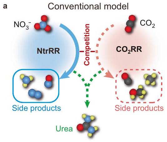
لتخفيف المنافسة بين المتزامنينويمكن أن يكون تقليل التفاعلات وتوزيعها زمنياً استراتيجية قابلة للتطبيق؛ أي أن تقليل كل مادة متفاعلة يحدث في نفس المكان ولكن في أوقات مختلفة ويفضل في مراحل مختلفة. توضح الشكل 1a الجدول الزمني للتفاعل للآلية التقليدية في عملية الاختزال لتخليق اليوريا، معمن المتوقع أن تكون أكثر تفاعلاً نسبياً منعلى المحفز. بالمقارنة، يتجنب الآلية التسلسلية (الشكل 1ب) هيمنة تفاعل اختزال النترات (NtrRR) على طول مسار التفاعل بأكمله. في البداية، يُفترض أن يحدث NtrRR قبلتفاعل اختزال )، وفي هذه المرحلة، معلق بسبب حركيات أدنى. عند النقطة التي يواجه فيها عملية NtrRR حاجز تفاعل رئيسي، يتم إيقاف المزيد من اختزال الوسيط المقابل، معتم تشغيلها في نفس الوقت. قبل إصدارالمنتجات،يجب أن يحدث الاقتران باستخدام الوسائط المسبقة NtrRR القريبة وتوجيه التفاعل نحو تكوين اليوريا. كشرط أساسي لهذه العملية التناقصية المتسلسلة، يجب أن يكون المحفز قادرًا على تغيير نشاطه التحفيزي لصالحبعد بدء NtrRR. ومع ذلك، لا نعلم عن أي محاولات سابقة لاستكشاف مثل هذا المحفز. بفضل الدراسات الحديثة التي أبلغت عن سلوك السعة الزائفة الفارادية لمواد الكربون المضافة بالنيتروجين (NC)، كنا مفتونين بحقيقة أن أنواع النيتروجين فييمكن أن undergo الكربون الهجين هيدروجينًا عكسيًا، مما يعني إمكانية استخدامه كمواقع نشطة ديناميكية أثناء التحفيز. جدوى التكوين العكسي والانفصال لـيمكن أن توفر الروابط على NC منصة جذابة لضبط النشاط التحفيزي ذاتيًاونحن نفترض أن هذه الميزة يمكن أن تنظم تسلسل تكوين الوسائط خلال تفاعلات الاختزال المشترك.
في هذا العمل، نقارن الأداء الكهروكيميائي بين محفز NC المعيب ومحفز ذرة مفردة يتم تحضيره باستخدام نفس الإجراء كما في السابق باستثناء إضافة سلفيد النحاس. كشفت الدراسات السابقة أن نشاط المحفزات ذات الذرة المفردة المنسقة بالنيتروجين البيريديني/البيرولي يعتمد بشكل رئيسي على مراكز المعادن المعزولة.. على وجه الخصوص، تم اعتبار أنواع النحاس ذات الذرة الواحدة نشطة في التحفيز و . هنا نوضح أنه بينما يتفوق في NtrRR مع نشاط جيد لـ، المنافسة الشديدة بين كلا عمليتي الاختزال على طول مسار التفاعل تؤدي إلى انخفاض إنتاج اليوريا. على العكس من ذلك، فإن المحفز NC لا يحفز فقط الاختزال المتسلسل لـوولكنه يتيح أيضًا سهولةالترابط، الذي يمنح أداءً تحفيزيًا استثنائيًا لتخليق اليوريا. مستفيدًا من هذه الميزات، فإن معدل إنتاج اليوريامع كفاءة فارادائية (FE) قدرهايتم تحقيقه على NC عند -0.5 فولت مقابل القطب الهيدروجيني القابل للعكس (RHE)
الشكل 1 | النماذج التقليدية والتتابعية لتخليق اليوريا كهربائيًا. حدوث متزامن لـ NtrRR و، مما يؤدي إلى إنتاج أقل من اليوريا وتكوين ملحوظ للمنتجات الجانبية، مثل تلك الناتجة عن NtrRR.
الذي يتفوق على معظم المحفزات التي تم الإبلاغ عنها سابقًا. إن سلوك الاختزال المتسلسل هذا ينشأ من تطور المحفز NC المدفوع بالتفاعل، مما يشكل سيناريو أرجوحة: أرجوحة التفاعل مائلة في البداية نحو NtrRR في وجودالأنواع على المحفز، خلال ذلكتتفكك الروابط وتصبح المراكز الحفازة مفعلة من أجل، مما يؤدي إلى إمالة الأرجوحة وتحويل التفاعل إلى تكوين *CO والمزيد من الترابط. بعد عملية التفاعل الكاملة، ستستعيد المراكز الحفازة حالتها الأولية بشكل تلقائي. يمكن أن تمنح هذه القابلية الديناميكية للعكس ميلاً عالياً لتكوين اليوريا، وبالتالي تؤدي إلى تثبيط غير مسبوق للتفاعلات الجانبية، مما يوفر استراتيجية لتصميم محفزات عالية الانتقائية لتخليق اليوريا كهربائياً.
النتائج
التحليل الهيكلي تم تحضير NC بواسطة طريقة التحلل الحراري في وعاء واحد باستخدام الجلوكوز والديسياندياميد كمصادر للكربون والنيتروجين، على التوالي.بينماتم الحصول عليه من خلال إضافة أخرى لـ (الشكل التكميلي 3). تظهر نتيجة حيود الأشعة السينية (XRD) لـ NC قمة حيود عريضة عند (الشكل التوضيحي 4)، والذي يمكن أن يُعزى إلى المستوى الجرافيتي النموذجي (002). يتم عرض نمط مماثل لـ، مما يعني غياب جزيئات النانو المعدنية. لا يمكن تعيين أي قمة لهيكل الترتيب طويل المدى في المستوى لكلا العينتين. تؤكد نتائج المجهر الإلكتروني على الشكل الشبيه بالورقة لكلتا العينتين وتكشف عن وفرة من الطيات والتجاعيد (الأشكال التكميلية 5-7). تقدم الشكل 2a وd صور المجهر الإلكتروني الناقل الماسح عالي الزاوية المصحح للانحراف (HAADF-STEM) لـ NC و، حيث تظهر الأخيرة بقعًا ساطعة تت correspond إلى ذرات النحاس المفردة الموزعة عبر الركيزة. تشير خريطة التحليل الطيفي بالأشعة السينية المشتتة للطاقة (EDS) إلى توزيع متجانس للنيتروجين في عينة NC (الشكل التكميلي 6). يتم الحفاظ على هذا التوزيع المتجانس بشكل جيد في (الشكل التوضيحي 7)، حيث يمكن أن تعمل الأنواع النيتروجينية كمواقع فعالة لالتقاط وتوزيع ذرات النحاس. تم تأكيد تشتت النحاس الذري بواسطة مطيافية الامتصاص بالأشعة السينية الممتدة (EXAFS)، مما يظهر وجود قمة قوية تُنسب إلى رابطة النحاس-نيتروجين (الشكل التوضيحي 8). تشير مطيافية الأشعة تحت الحمراء بتحويل فورييه (FTIR) أيضًا إلى تكوين الأنواع فيشبكة مترافقة من الكربون الجرافيتي (الشكل التكميلي 9)يمكن استكشاف الإلكترونات الممنوحة من ذرات النيتروجين مباشرة من خلال طيف الرنين المغناطيسي الإلكتروني (EPR) (الشكل التكميلي 10). علاوة على ذلك، فإن الظهور المتزامن لـ و ت peaks في طيف رامان لـ NC (الشكل التكميلي 11) تشير إلى وجود العديد من العيوب في الهيكل، والتي هي متأصلة في عملية الكلسنة أثناء التخليق. يتعلق بهذه الميزة مساحة سطح محددة عالية منكما تم تقديره من
ترتيب متسلسل من NtrRR و، مما يؤدي بشكل متتابع إلى تحيز المنافسة بين كلا التفاعلين لصالح واحد منهما ويؤدي إلى انتقائية عالية في تخليق اليوريا. رموز الألوان: N، أزرق؛ O، أحمر؛ C، أسود؛ H، أصفر.
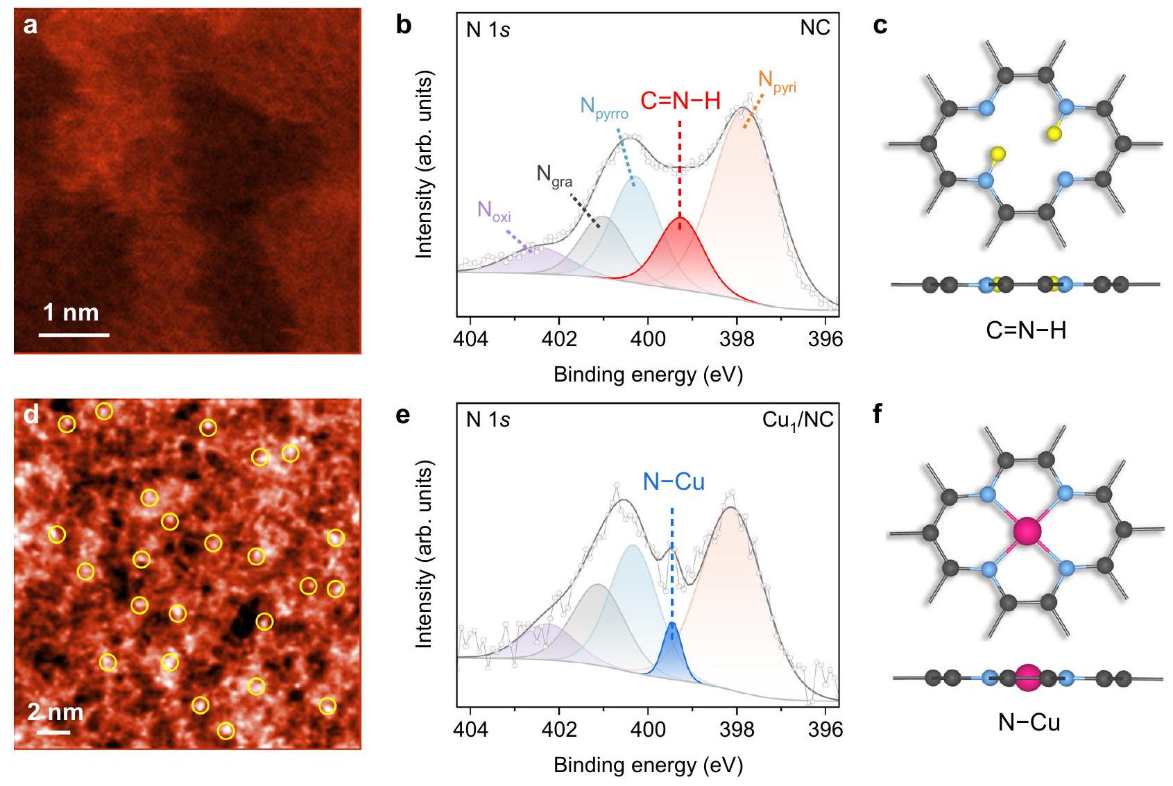
الشكل 2 | التوصيف الهيكلي لـ NC و. أ، صور HAADF-STEM لـ NC (أ). ب، هـ طيف XPS لـ NC (ب). ج، الهياكل المحلية النموذجيةأنواع في و أنواع فيرمز اللون: N ، أزرق؛ C ، أسود؛ H ، أصفر؛ Cu ، وردي.
مخططات بروناور-إيميت-تيلر (BET)، وتحتفظ قيمة مماثلة لـ NC (الأشكال التكميلية 12 و 13). نلاحظ أنه لا يوجد أثر واضح لـتم الكشف عنه في جميع طيف FTIR وطيف رامان.
تم إجراء مطيافية photoemission بالأشعة السينية (XPS) لتوصيف الأنواع النيتروجينية والنحاس على NC و (الأشكال التكميلية 14-16). الـيمكن تحليل طيف NC (الشكل 2b) إلى مكونات تتوافق مع النيتروجين البيريديني (397.9 إلكترون فولت)، نيتروجين بيروليكن (الجرافيتي) ) ، ن مؤكسد ( ) و . لطيف N 1s طيف XPS لـ (الشكل 2e)، يظهر قمة حادة عند 399.5 إلكترون فولت، والتي يمكن تصنيفها إلى سنداتاستبدال الواسع الذروة. وبناءً عليه، يمكننا أن نتوقع أن دمج ذرات النحاس الفردية يمكن أن يخفف من الروابط عند ذرات النيتروجين البيريدينية/البيرولية في NC. تتوافق هذه النتائج مع العمل الأخير الذي أظهر إزالة الهيدروجين من الكربون المدعوم بالنيتروجين عند مواقع التثبيت لذرات المعادن الانتقالية خلال تخليق المحفزات ذات الذرة الواحدة. لقد قمنا بإجراء حسابات نظرية الكثافة الوظيفية (DFT) لتقييم الطاقة.تكوين الروابط على NC (الشكل التوضيحي 17). تكوين لأربعة نيتروجينات بيريدينية مجاورة (المشار إليها بـ ) في ورقة جرافين، والتي هي مماثلة لـ نصففي (الشكل 2f) ولكن دون وجود النحاس، تم اعتباره كنظام نموذجي لدراسة الأنواع. إن ارتباط أول ذرة هيدروجين بأحد ذرات النيتروجين هو تفاعل طارد للحرارة بشكل كبير، مع تغيير في الطاقة الحرة ( ) من -0.72 إلكترون فولت عند 0 فولت مقابل RHE. الهيدروجين الثاني يفضل الامتصاص على ذرة نيتروجين أخرى أبعد عن السابقة، مما يعطي تغيرًا في الطاقة الحرة ( ) من -0.62 إلكترون فولت. نظرًا لارتباط التاليين المتتاليين الذرات المتبقية ستستهلك الذرات طاقة كبيرة (1.16 و 1.23 إلكترون فولت، على التوالي)، ومن غير المحتمل أن يتم احتجازها في ظروف تجريبية. وبالتالي، فإن كل بيريدينيكستقوم الجزيئات بالتقاط ما يصل إلى ذرتين من الهيدروجين بشكل تلقائي (الشكل 2c). إزالتها القابلة للعكس في تفاعلات الكهروكيميائية تشكلت كفرضية للسعة الزائفة الفارادية لـ.
أداء التحفيز الكهربائي في تخليق اليوريا
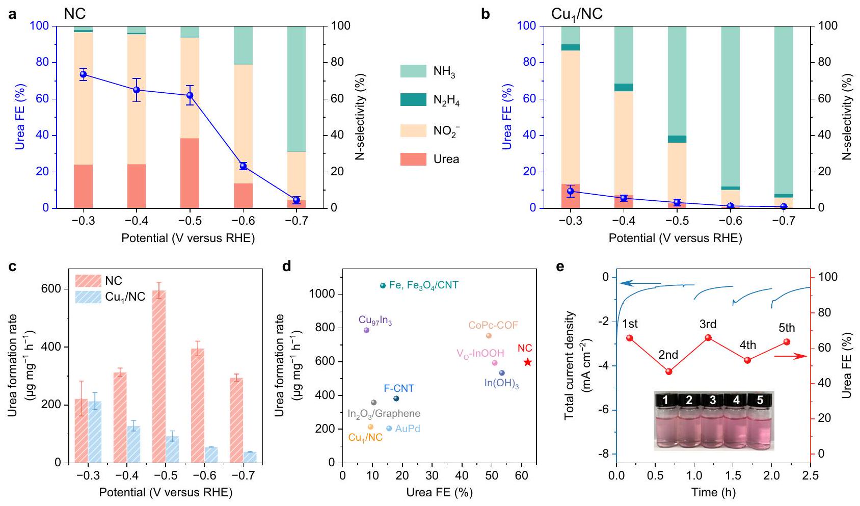
تقييم الانتقائية الكهروكيميائية لـ NC وتم إجراء تخليق اليوريا في خلية من نوع H (الشكل التكميلي 18) عبر طريقة الكرونو-أمبيرومترية (CA). يتكون المحلول الكهربائي من و تم اعتماده، ونقاء عاليتمت المحافظة على التشبع من خلال فقاعات مستمرة أثناء التحليل الكهربائي. تم قياس تركيز اليوريا بطريقة دياستيل مونوكسيم (الشكل التكميلي 19).. بالإضافة إلى اليوريا، هناك سلسلة من المنتجات الجانبية، بما في ذلك الأمونيا ( ) ، نيتريت ( الهيدرازين ) ، أول أكسيد الكربون ( CO ) والهيدروجين ( )، تم تحديدها أيضًا من خلال التحليل الطيفي الضوئي وتحليل الكروماتوغرافيا الغازية (الأشكال التكميلية 20-22). تم حساب متوسط عائدات المنتج عند كل جهد على مدار ثلاث قياسات مستقلة. كما هو موضح في الشكل 3a والشكل التكميلية 24، فإن اليوريا هي المنتج السائد على محفز NC من -0.3 إلى -0.5 فولت مقابل RHE. وفقًا لعائدات المنتجات المحتوية على النيتروجين، تم الحصول على انتقائية النيتروجين، مما يظهر نسبة مرتفعة نسبيًا من تحول إلى. على الرغم من ذلك، فإن FE من المنتج محدود إلى حد ما مقارنةً بمادة اليوريا، نظرًا لعدد الإلكترونات المنقولة الأقل بكثير للتحويل إلىأكثر من اليوريا. علاوة على ذلك، يتم تثبيط تفاعل تطور الهيدروجين (HER) بشكل كبير على NC (الشكل التوضيحي 25) مقارنةً بتلك المحفزات المصممة سابقًا لتخليق اليوريا.. تمثل هذه الميزة واحدة من أهم الخصائص للاختيارية الفائقة لليوريا على NC.
على النقيض،يقدم FE أقل من 15% تجاه اليوريا مع تكوين مفرط للمنتجات الجانبية (الشكل 3ب)، من بينها منتجات NtrRR (وتتولى القيادة في النطاق الكامل المحتمل الذي تم التحقيق فيه. نظرًا للتشابه التام في إجراءات التخليق لكل من
الشكل 3 | الأداء الكهروتحفيزي لتخليق اليوريا على NC و. الخصائص الكهربائية لليوريا وانتقائية النيتروجين لجميع المنتجات المحتوية على النيتروجين تحت إمكانيات مختلفة على و . معدل إنتاج اليوريا عند إمكانيات مختلفة. د مقارنة معدل تشكيل اليوريا وكفاءة التحويل بين NC ومواد التحفيز الأخرى المبلغ عنها في الأدبيات، بما في ذلك في أنابيب الكربون النانوية“إن أوه” الناقص الأكسجينالكربون المضاف إليه الفلور أنابيب نانوية (F-CNT)إطار عضوي تساهمي قائم على الفثالوسيانين (CoPc-COF)، و تم جدول القيم المقابلة في الجدول التكميلي 1. e اختبار الاستقرار لـ NC عند -0.5 فولت مقابل RHE لمدة 5 دورات. يوضح الشكل الداخلي أن لون المحلول الذي تفاعل مع دياستيل مونوكسيم يكاد يكون متطابقًا خلال الدورات.
NC و، من المحتمل أن يكمن الاختلاف الرئيسي بينهم في و الأنواع بناءً على ما إذا كانت أيونات النحاس قد تم دمجها. وقد تم تأكيد هذه التكهنات من خلال نتائج XPS الموضحة في الشكل 2b، e. وبالتالي، يمكننا أن نفترض أن الفارق الكبير في أداء تخليق اليوريا يجب أن يُعزى إلى الأنواع المذكورة أعلاه، والتي يمكن أن تعمل كالمراكز الحفازة لتقليلوعلاوة على ذلك، قمنا بدراسة محفزات ذرات مفردة أخرى، بما في ذلك و للتقليل المشتركو (الشكل التوضيحي 26). يتم تشكيل كميات ضئيلة فقط من اليوريا لكل من المحفزين بسبب التنافس في NtrRR. التأرجح بينوالتقليص يميل دائمًا نحو السابق، مما يعيقالترابط، الذي يبدو أنه حالة شائعة في المحفزات ذات الذرة الواحدة المدعومة بالكربون.
يظهر تأثير الجهود المطبقة على معدل إنتاج اليوريا في الشكل 3c. بالمقارنة مع، ينتج المحفز NC عوائد أعلى بكثير عند -0.5 فولت مقابل RHE. على الرغم من أن الكثافة الحالية الإجمالية التي يتم توصيلها بواسطة (الشكل التوضيحي 27)، يستهلك معظم الإلكترونات لتوليد منتجات جانبية، مما يؤدي إلى انتقائية ضعيفة بشكل ملحوظ لـ اقتران. الاقتران هو خطوة مستقلة عن الجهد، وعندما يكون الجهد السالب كافيًا، ستكون هذه الخطوة التفاعلية أقل ملاءمة حركيًا من الاختزال المفرط للوسطاء إلى منتجات جانبية. يمكن أن يفسر هذا الانخفاض في غلات اليوريا لـ NC عند -0.5 إلى -0.7 فولت مقابل RHE. ومن الجدير بالذكر أن محفز NC يمكّن من تخليق اليوريا كهربائيًا بمعدل غلة أقصى قدرهمع FE واعد بـأقل من -0.5 مقابل RHE، وهو أفضل من معظم المحفزات التي تم الإبلاغ عنها مؤخرًا والتي تعمل عند إمكانيات مماثلة (الشكل 3d). أظهر اختبار المتانة لـ NC تقريبًا عدم تدهور في أي من النشاط أو انتقائية اليوريا خلال 5 جولات متتالية (الشكل 3e والشكل التكميلية 28). تم إجراء قياسات TEM بعد الاختبار (التكميلية
الشكل 29)، مما يظهر أن مورفولوجيا المحفز NC تبقى سليمة إلى حد كبير. إن النشاط الكهروكيميائي المستدام لا يظهر فقط الاستقرار على المدى الطويل لـ NC، بل يشير أيضًا إلى أن مصادر النيتروجين والكربون تأتي منوبدلاً من أن تكون من ذرات النيتروجين الكينولية/البيرولية والكربون في المحفز. بالإضافة إلى ذلك، قمنا بتخليق عينة NC أخرى عند درجة حرارة تحلل مرتفعة، مما يؤدي إلى تقليل كبير في الكمية منالأنواع وتظهر نسبة منخفضة جداً من اليوريا في تفاعل الاختزال المشترك (الأشكال التكميلية 30 و31). وهذا يعني أنتلعب دورًا محوريًا في تخليق اليوريا على NC.
تجارب التحكم للتفسير الميكانيكي
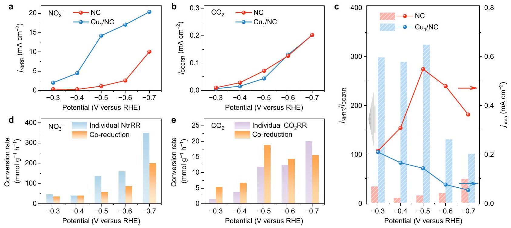
لفهم خاصية التحفيز الكهربائي لـ NC بشكل أفضل وقمنا بإجراء تجارب تحكم لتقييم نشاطهم لـ NtrRR وبشكل منفصل. في الاختبارات الكهروكيميائية لـ NtrRR الفردية، تم استخدام غاز الأرجون بدلاً منتم تغذيته في الإلكتروليت. فوق محفز NC،تم الكشف عنه كمنتج رئيسي في مقابل RHE (الشكل التوضيحي 34)، بينما تشكيل هيمن علىمع وصول FE إلى ما يقرب من عند إمكانيات سالبة تتجاوز -0.5 فولت مقابل RHE. نجد أن يمكن أن يوفر كثافة تيار NtrRR أعلى بكثير (بما في ذلك تشكيل و ) من NC (الشكل 4أ). نظرًا لأن هو المنتج الأكثر اختزالًا على طول مسار تفاعل NtrRR، تشير النتائج أعلاه إلى أن استبدالبواسطةيمكن أن يعزز الحد الأقصى منبشكل حدسي،قد يبدو مفيدًا لتخليق اليوريا الكهربائي لأن تشكيل اليوريايتطلب أيضًا الحد الأقصى من تقليل N فيإلى حالة تكافؤ -3. ومع ذلك، كما هو موضح أدناه، فإن انتقائية اليوريا ستتأثر سلبًا في الواقع بعملية NtrRR السهلة عندماتظهر العملية نشاطًا أقل بكثير مقارنةً بـ NtrRR. الشكل 4ب و
الشكل 4 | تجارب التحكم لـ NtrRR الفردي وعلى NC و. كثافة تيار NtrRR (، والتي تتوافق مع مجموع كثافات التيار الجزئي لـ و ) خلال التخفيض الفردي لـ . ب كثافة التيار، والذي يتوافق مع كثافة التيار الجزئي لـ CO) خلال الاختزال الفردي لـ. ج النسبة بين و ، وكثافة التيار الجزئي لليوريا ( ) أثناء الاختزال المشترك لـ و. معدل التحويل لـإلى المنتجات المحتوية على N في NC في NtrRR الفردية مقارنة بتفاعل الاختزال المشترك. e معدل التحويل لـإلى المنتجات المحتوية على C في NC بشكل فرديمقارنة بتفاعل الاختزال المشترك.
الشكل التكميلية 35 يقدم نتائج الفرديةتجارب التخفيض، حيثتمت إزالته من الإلكتروليت وتم تشغيل المحفزات تحتتدفق الغاز. بينما تم اشتقاقكثافات التيار الحالية متشابهة بين NC وهم أصغر بمقدار ترتيب واحد من حيث الحجم من كثافات التيار في NtrRR الفرديةالتقليل. نتائج حسابات DFT تؤكد هذه النتيجة، كاشفة أن الخطوة الأولى من الهدرجة“، أي، *، هو محدد المعدل ويمتص الحرارة بشدة ( ) لكلا من NC و (الشكل التوضيحي 36). مع التوازن بين NtrRR وضرب أثناء الاختزال المشترك لـوسيكون هناك فرصة محدودة لتكوين اليوريا في مركز تحفيزي واحد إذا ظلت نشاطات هذا الموقع دون تغيير في التفاعلات. يتوافق مع السيناريو أعلاه، والذي يُرى بشكل أفضل عندما يصبح الجهد أكثر سلبية. علىنشاط لكل من NtrRR الفردي ومن الواضح أنها تمت ترقيتها من -0.3 إلى -0.7 فولت مقابل RHE (الشكلبينما يظهر عائد اليوريا اتجاهًا تنازليًا (الشكل 3c). إن المنافسة الشديدة بين كلا التفاعلين عند إمكانيات أكثر سلبية تشرك عملية الاختزال المشترك في حالة أكثر عدم توازن. إن عملية NtrRR السائدة، التي تستفيد أكثر من الجهد المائل مقارنةً بالجهد المستقل عن ذلك.عملية الاقتران، ستعيق بشكل كبير تكوين اليوريا. على عكسيمكن لمحفز NC توجيه الاختزال المشترك لـوعلى طول مسار تكوين اليوريا. نوضح في الشكل 4c أنه بالمقارنة مع، النسبة بين NtrRR وكثافات التيار في التجارب الضابطة أقل بكثير. من الواضح أن NtrRR على NC يحتل موقعًا أقل هيمنة من ذلك على، مما قد يوفر فرصة أكبر لـ الاقتران خلال تفاعل الاختزال المشترك. نقطة أخرى تستحق الذكر هي أنه على NC، معدل التحويل لـكما تم الحصول عليه من معدلات العائد لليوريا وCO (في ) في التخفيض المشترك يتجاوز ذلك في الفردي من -0.3 إلى -0.6 فولت مقابل RHE (الشكل 4e). وهذا يشير بوضوح إلى أن التحويل الكهروكيميائي لـيمكن تفعيله في وجودوفقًا لحسابات DFT، يمكننا استبعاد احتمالالترابط بينوالوسطاء الرئيسيون لـ NtrRR على NC (الشكل التوضيحي 37). ومن ثم، فإن الهدرجة لـ، خاصةً العامل المحدد للتقييم * * خطوة COOH فيمطلوب لليوريا معلومات. في هذا السياق، تم الترويج لـستشير التحويل إلى أن عملية NtrRR تلعب دورًا غير تافه في تقليل استهلاك الطاقة في هذه الخطوة الأساسية. يمكن تفسير هذا التخفيض على أنه تغيير في نشاط المحفز ناتج عن NtrRR.
من الجدير بالذكر أننا نجد أنه على المحفز NC، فإن معدل التحويل لـ إما أن يتأثر بشكل طفيف أو ينخفض بشكل كبير عند إدخال كمواد متفاعلة (الشكل 4d). وهذا يعني أن وسائط NtrRR يمكن أن تشارك في عملية تكوين اليوريا ولكن يبدو أنها غير قادرة على أن تُفعّل منالمتوسطات. يتم عرقلة NtrRR حتى بوجودإلى حد ما. بالنظر إلى أن جهد البداية لـ NtrRR أكثر إيجابية من (الشكل التوضيحي 38)، يمكن الاستنتاج بأمان أن NtrRR يسبقأثناء تخليق اليوريا. في هذا السياق،يتم تقليله أولاً في المركز الحفاز وتستمر التفاعل إلىعبر خطوتين من الهدرجة (تغير تكافؤ النيتروجين من +5 إلى +3). نظرًا لأن FE منفي NtrRR الفردي هو تقريبًافي مقابل RHE (الشكل التوضيحي 34)، فقط كمية ضئيلة من يمكن تقليلها أكثر في هذا النطاق المحتمل، مما يمكن أن يقضي على إمكانية أن تكون منتجات التخفيض تتجاوزيمكن أن يشارك في الاقتران أثناء الاختزال المشترك. وهذا يشير إلى أن تغيير مسار التفاعل إلى من المرجح أن يتم إنجازه في فترة التشكيل. بعد ذلك، يحدث في محيط الوسائط/المنتجات NtrRR التي تم تشكيلها سابقًا، ويمكن أن تتفاعل الوسطيات بسهولة مع هذه الأنواع المحتوية على النيتروجين لتكوين اليوريا. وقد دفعتنا الاعتبارات المذكورة أعلاه إلى اقتراح أن الاختزال المشترك لـوعلى NC يعتمد نموذجًا تسلسليًا من خلال تبديل متتالي بين تفاعلين اختزاليين.
تتبع العمليات للأنواع السطحية
يمكن أن توفر تقنية مطيافية الامتصاص بالأشعة تحت الحمراء المعززة بواسطة الانعكاس الكلي المخفف (ATR-SEIRAS) تفاصيل حاسمة لفهم أفضل لـوآلية الاختزال المشترك على محفز NC. الشكل 5a يظهر طيف ATR-SEIRAS مع تطبيق جهد يتراوح من 0 إلى -0.7 فولت مقابل RHE، حيث تم الكشف عن عدة نطاقات تحت الحمراء في نطاقات الأعداد الموجية من 1000-2000 و. فرقتان عند حوالي 1625 ويمكن أن يكون المخصصة لوضعيات الانحناء والتمدد (بما في ذلك المكونات المتماثلة وغير المتماثلة) لـعلى التواليكلاهما يظهر زيادة ملحوظة في الشدة من -0.5 إلى -0.7 فولت. هذا يتماشى مع الزيادة في الإنتاج منعند الفولتية التي تقترب من -0.7 فولت كما كشفت التجارب الكهروكيميائية. الحزم التي تتركز حول 1483 وتتوافق مع غير المتماثلاهتزاز الشد لليوريا واهتزاز الشد للوسطاء التفاعليين، على التواليبينما وضع التمدد لـيلاحظ أيضًا في. تزداد شدتها بشكل مستمر عند الفولتية من 0 إلى -0.5 فولت وتتطور بشكل معتدل بعد ذلك، مما يعكس النجاح الترابط وإنتاج اليوريا في هذا النطاق من الجهد أثناء الاختزال المشترك لـو.
لتوضيح التغيرات في المركز الحفاز على NC خلال تفاعلات الاختزال، نقوم بدراسة تطور الأنواع في NtrRR الفردية بواسطة ATR-SEIRAS أثناء التشغيل. لتقليل التأثير من المنتجات، يتم مسح الجهد من 0 إلى -0.15 فولت؛ عند الجهود السلبية الأكثر، يتشكلسيتم البدء. نؤكد أنه بينما تمثل القمم الإيجابية في طيف ATR-SEIRAS زيادة في تركيز الأنواع المقابلة عند السطح أو بالقرب منه، يمكن أن تُعزى القمم السلبية إلى انخفاض في تركيز الأنواع الموجودة. كما هو موضح في الشكل 5b، تظهر قمة سلبية عندالذي يُنسب إلىاهتزاز التمدد، وتزداد شدتها عند الجهود الكاثودية الأكثر. وهذا يشير إلى أن البروتونات الموجودة الأنواع في المحفز NC تتناقص في المرحلة الأولية من NtrRR، بما يتماشى مع الدراسات السابقة التي تظهر سهولة الانفصال عن السندات على . لذلك، يمكننا أن نستنتج أن عملية NtrRR تستهلك البروتونات مباشرة علىالأنواع. من المتوقع أن يؤدي هذا التغيير في المركز الحفاز إلى حدوث تغيير في النشاط، مما يخلق الفرصة لتحويل مسار التفاعل إلىوتمكين الآلية التتابعية لـوالاختزال المشترك إلى اليوريا. بعد تكوين اليوريا، تكون القوة الديناميكية الحرارية العالية كما ذُكر أعلاهيمكن أن يؤدي إلى إعادة الهيدروجين لـ NC، ويمكن أن تعمل الأنواع -H كمراكز نشطة تتطور ديناميكيًا في تفاعل الاختزال المشترك. نلاحظ أن هذاميزة النضوب بالكاد يمكن تمييزها علىفي حالة التشغيل ATR-SEIRAS (الأشكال التكميلية 39 و 40).
تم إجراء مطيافية رامان في الموقع أيضًا لمراقبة الأنواع السطحية أثناء التفاعل الحفزي. كما هو موضح في الشكل 5c، يوجد ذروة عندالمطابقة لوضع التمدد المتماثل لأيون النتراتيتم ملاحظته. القمم التي ظهرت عند 1170 ويمكن أن يُنسب إلى اهتزاز الشد لـ و على التوالي، مما يشير إلى تشكيلها في الاختزال المشترك لـو-نظير وتم إجراء تجارب موسومة بالنظائر (الشكل 5d) تحت جهد مطبق قدره -0.5 فولت مقابل RHE معوكإلكتروليت وغاز تغذية. تظل مواقع حزم D وG لـ NC دون تغيير بغض النظر عن النظير المستخدم. قمة رامان لـيظهر النطاق انزياحًا أحمر فيتجارب استبدال النظائر، وذرواتمن الواضح أنها انتقلت إلى قيم أقل مقارنة بـتؤكد هذه النتائج أن كل من مصادر النيتروجين والكربون في اليوريا تأتي من المواد الخام المستخدمة بدلاً من المجموعات الوظيفية على محفز NC.
الشكل 6 | مسار التفاعل المقترح لتفاعل الاختزال المتسلسل على NC. أ ملف الطاقة الحرة غيبس المحسوب بواسطة DFT لتفاعل الاختزال المشترك لـ و عند 0 فولت مقابل RHE. الخطوات الأساسية المميزة بالخطوط المتقطعة أقل ملاءمة من تلك المميزة بالخطوط المستمرة. حالات الانتقال (TS) لـ *CO إزالة الامتصاص ) و اقتران ( تم الحصول على ( ) من خلال حسابات CI-NEB. ب تكوينات هيكلية للوسطاء التفاعليين الحرجين. الوسطاء في الإطار مرتبطون بآلية الاختزال المتسلسل التي تؤدي إلى تكوين اليوريا.
حسابات DFT لآلية الاختزال المتسلسل من خلال الاستفادة من حسابات الطاقة الحرة لجيبس باستخدام نظرية الوظائف الكثيفة، يمكننا معالجة مسار تفاعل تخليق اليوريا على المحفز NC، مما يدعم بقوة سيناريو الاختزال المتسلسل. البيريدين الهيدروجينيموقع مع ذرتين هيدروجين مرتبطتين (التكوين 1 في الشكل 6، المشار إليه بـ ) تم اعتباره المركز الحفاز التمثيلي. في البداية، ستحدث NtrRR بسهولة بينما يُعتبر غير مفضل بسبب الحاجز الكبير لتكوين * COOH (2). على الرغم من أنيمكن تقليله إلى *في خطوة كيميائية كهربائيةيمكن أن يحدث هذا التحويل أيضًا من خلال نقل الإلكترون المرتبط بالبروتون من المحفزبعبارة أخرى،يستخرج زوجًا من البروتون والإلكترون من إزالة الهيدروجين منالموقع، مما يترك واحداًعلىالموقع وتشكيل تكوين لـ، الذي هو ماص للحرارة بمقدار 0.08 إلكترون فولت فقط. نجد أن *المتوسط لا يمكنه الارتباط كيميائيًا بالعامل المساعد، ولكنه في الواقع محاصر بواسطة قوى فان دير فالس ويقع على مسافة حواليمن المركز الحفاز (الشكل التكميلي 41). وبالمثل، *NOOH (4) و *NO (6) هي ممتص جسديًا بدلاً من كيميائيًا على المحفز. لقد أدت الطبيعة المستقلة لهذه الوسائط إلى انخفاض تداخل الحالات الإلكترونية بين الجزيئات الممتصة والمح catalyst. على وجه الخصوص، يوجد فجوة طاقة قدرها 1.05 إلكترون فولت بين أدنى مدار جزيئي غير مشغول (*NOOH) ومستوى فيرمي في التكوين 4 (الشكل التكميلي 42). تشير هذه النتيجة إلى أن طاقة كبيرة مطلوبة لحقن إلكترون من المحفز إلى جزيء *NOOH الممتص، مما يفرض قيودًا صارمة على اختزاله الكهروكيميائي. بالمقارنة، فإن عملية إزالة *NOOH (4) مواتية من الناحية الطاقية، حيث تكون طاردة للحرارة بمقدار -0.05 إلكترون فولت، مما يوفر فرصة كبيرة لكشف الـموقع مع واحد الذرة المتبقية (5). الامتزاز السهل والهجرة لـ التي تم العثور عليها من خلال حسابات DFT تتماشى مع الملاحظة التجريبية بأن المحفز NC انتقائي نحوتشكيل أثناء التخفيض الفردي.
بعد ذلك، من التكوين 5، التأثير الستيري المنخفض في المركز الحفاز بسبب غيابيعمل لضمان سهولة و عمليات الاقتران. تؤدي التأثيرات الفراغية إلى تفاعل قوي بين *COOH و NC المحفز (الشكل التكميلي 43)، وهو السبب وراء الانخفاض الملحوظ في استهلاك الطاقة فيخطوة مع واحد مقارنةً بذلك مع اثنين الذرات ( 1.73 إلكترون فولت ). الميل العالي لـ في هذه المرحلة يدعم تخميننا أنيمكن تعزيز التحويل بعد NtrRR. يحدث الانقسام التالي لمسار التفاعل عند *CO، الذي سيخضع إما للإزالة أو اقتران C-N. نظرًا لأن كلا الخطوتين هما عمليات تهيمن عليها الديناميكا، فقد استخدمنا هنا تقنية الحزام المرن المدفوع بصورة متساقطة (CI-NEB).حسابات (الشكل التوضيحي التكميلي 44) لتحديد حواجز التنشيط الخاصة بهم. تظهر النتائج أن الحاجز لتكوينأعلى بكثير من *CO(NOOH) (9)، مما يتوافق تمامًا مع الانتقائية الأقل لمنتج CO في التجارب. ثم، الـ *يتعرض الوسط لثلاث خطوات متتالية من الاختزال الكهروكيميائي ويطلق جزيئين من الماء لتكوين *CON (10)، حيث يتم في هذه المرحلة الثانيةيحدث الاقتران باستخدام آخربالقرب. ستخضع المادة الوسيطة الناتجة *NCO(NOOH) (11) للاختزال إلى اليوريا، وجميع الخطوات الأساسية بينهما هي تلقائية حرارياً (الشكل التوضيحي 45) باستثناء *NCO(NO) * خطوة (0.34 إلكترون فولت). بعد أن يغادر جزيء اليوريا سطح المحفز،سيتم هدرجة الموقع على الفور، مما يؤدي إلى تجديد الـالتكوين (الشكل التوضيحي الإضافي 17).
مجتمعة، توفر لنا نتائج DFT في الشكل 6 صورة شاملة لآلية الاختزال المتسلسل على NC. في جوهر هذه الآلية تكمن القدرة على التغيير الهيكلي لمركز التحفيز (بين 1 و 5)، والتي هي ديناميكية وقابلة للعكس في عملية تشكيل اليوريا. للمقارنة، تم إجراء حسابات DFT أيضًا لـ. الـالجزء المقابل هو المركز الحفاز، الذي قد لا يخضع للهدرجة بسبب تشبع جميع ذرات النيتروجين. يتم بدء عملية NtrRR عن طريق الاختزال الكهروكيميائي لـ، تليها مزيد من التخفيض إلى *NO مع مشهد طاقة مسطح (الشكل التكميلي 48). نلاحظ أنه على عكس المحفز NC، جميع الوسائط علىترتبط كيميائيًا بالمركز الحفاز (الشكل التكميلي 49)، مما يتجنب تعرض المركز الحفاز لمتفاعلات أخرى. تستمر NtrRR في التقدم حتى تشكيلتم الانتهاء منه، مع جهد محدود قدره 0.31 فولت. من ناحية أخرى، الـالعملية بطيئة بسبب الطابع العالي الامتصاص للحرارة * * خطوة COOH ( 1.59 eV )، مشابهة لحالة موقع مع اثنين الذرات. كما أن يبقى المحفز سليماً طوال التفاعلات، وسيكون من الضروري إدخال كمية هائلة من الطاقة الحرة لتنشيط هذه الخطوة وتوفير وسيط *CO، الذي لا غنى عنه لتكوين اليوريا. وهذا يشير إلى أنهو المنتج الأكثر سهولة في الوصول في الاختزال المشترك لـوعلى“، مما يظهر توافقًا جيدًا مع النتائج التجريبية. قد يوفر التفسير المقترح أيضًا تفسيرًا للتغير في انتقائية المنتج على : الإجمالي الانتقائية التي لوحظت تجريبيًا عند -0.7 فولت مرتبطة بالتنافس على المراكز الحفازة بين NtrRR وبينما ستؤدي الإمكانيات الأقل سلبية إلى منافسة أقل حدة، وبالتالي المزيد من الفرص الوفيرة للتقليل المتزامن من كلا المتفاعلين.
نقاش
في هذا العمل، يتم تصنيع اليوريا الانتقائي عبر عملية اختزال متسلسلة باستخداموكمتفاعلات مقترحة ومثبتة على محفز كربوني مخدر بالنيتروجين. يوفر هذا المحفز NC معدل إنتاج يوريا قدرهمع FE مرتفع عند -0.5 فولت مقابل RHE، يتفوق على معظم المحفزات التي تم الإبلاغ عنها سابقًا ويظهر إمكانات كبيرة في التطبيقات على نطاق واسع. في تناقض حاد مع NC، يظهر المحفز ذو الذرة الواحدة انتقائية أقل بكثير لليوريا، والتي تنشأ من المنافسة الشديدة والمستمرة بين اختزالوفي مركز تحفيزي واحد. استنادًا إلى تجارب مصممة بشكل عقلاني، وقياسات في ظروف التشغيل، وحسابات نظرية دالة الكثافة، نكشف عن الدور الأساسي لـنوع غير NC التي يمكن أن تعمل كمواقع نشطة ديناميكية. يتم التحكم في تفضيل التفاعل بشكل جوهري من خلال العدد من الروابط ويمكن تبديلها بين تفضيل عملية NtrRR أو عملية، حيث تكون تفاعلات الاختزال متسلسلة وموجهة نحو تكوين اليوريا. يمكن أن يشكل الفهم الأساسي لنموذج التفاعل المتسلسل أساسًا لتعزيز تطوير المحفزات الكهربية الانتقائية للسماح بسهولةترابط وتخليق فعال لليوريا.
طرق
تركيب NC و
تم تحضير NC من خلال طريقة التحلل الحراري ذات الخطوتين، باستخدام الجلوكوز (GC) وثنائي سيانيد الدياميد (DCDA) كمصدر للكربون ومصدر للنيتروجين، على التوالي. تم شراء GC وDCDA من سيغما-ألدريش، وتم استخدامهما مباشرة دون معالجة إضافية. تم خلط GC مع DCDA بنسبة كتلة قدرها، وتمت عملية التلبيد للمزيج تحت تدفق الأرجون عندلمدة 6 ساعات لتشكيل. بعد ذلك، تم كربنة المنتج الناتج في لمدة 3 ساعات في جو من الأرجون. عملية التحضير وكانت المحفزات أحادية الذرة الأخرى مماثلة لتلك الخاصة بـ NC، باستثناء إضافة المواد الأولية المعدنية مثل. أخيرًا، تم إزالة تجمعات جزيئات المعدن عن طريق غسل المحفزات جيدًا في .
التوصيفات خارج الموقع وداخل الموقع
تم جمع أنماط حيود الأشعة السينية على جهاز حيود من نوع Bruker D8 Advance مزود بـالإشعاع، المسح منإلىمعدل المسح بـتمت دراسة التركيب والشكل للعينات باستخدام مجهر إلكتروني مسح ميداني (ZEISS SUPRA).تم إجراء تجارب XPS على جهاز ESCALAB 250X (ثيرمو فيشر).
تم قياس ATR-SEIRAS الكهروكيميائي أثناء التشغيل بواسطة مطياف FTIR INVENIO R (Bruker) المزود بكاشف من الزئبق والكادميوم والتيلوريوم (MCT).تم استخدام قطب كهربائي ورقة من البلاتين كقطب مرجعي وقطب مضاد، على التوالي. خلال جمع الطيف، تم تطهير المسار البصري باستمرار بغاز النيتروجين لتقليل الاضطراب الناتج عن الماء وفي الهواء.إلكتروليت مشبع يحتوي على و تم استخدامه في عملية تفاعل تقليلو. تم الحصول على طيف الخلفية لقطب التحفيز عند جهد الدائرة المفتوحة قبل كل قياس. ثم، تم قياس أطياف الامتصاص (- ) عند إمكانيات مختلفة تم جمعها بدقة طيفية من في طيف ATR-SEIRAS، تشير القمة السلبية إلى أن مادة معينة أو مجموعة وظيفية قد تم استهلاكها، بينما تشير القمة الإيجابية إلى أن مادة معينة أو مجموعة وظيفية قد تم إنتاجها أو زادت.
تم إجراء توصيف رامان في الموقع في خلية ثلاثية الأقطاب مزودة بنظام ميكروسكوب رامان متماسك (رينشاو إنفيا). كانت الطول الموجي 532 نانومتر مععدسة المجهر. خلال عملية الاختبار، كانت المسافة بين نافذة الياقوت والقطب الكهربائي أقل من 0.1 نانومتر، مما يضمن أن تأثير التوهين لطبقة المحلول على إشارة رامان يمكن أن يكون صغيرًا قدر الإمكان.
القياس الكهروكيميائي
تم إجراء القياس الكهروكيميائي باستخدام تكوين ثلاثي الأقطاب باستخدام محطة كهروكيميائية CHI 660E في خلية من النوع H. تم معالجة نافييون 115 (دوبونت) مسبقًا واستخدامه لتجميع خلية من النوع H. تم تسخين غشاء نافييون أولاً فيفيلمدة ساعة واحدة وتم شطفه بالماء المقطر. ثم تم تسخينه مرة أخرى فيفيلمدة ساعة واحدة وتم شطفه مرة أخرى بالماء المقطر.ومشبعة بـتم توظيفه، مع إلكترود (في كلوريد البوتاسيوم المشبع) ورقة بلاتينية ) استخدمت كإلكترود مرجعي وإلكترود مضاد، على التوالي. تم توزيع 1 ملغ من مادة المحفز في ماء منزوع الأيوناتإيزوبروبانول ونافيوينمحلول مائي)، ثم تم استخدام الموجات فوق الصوتية لمدة 3 ساعات تحت حمام من الماء المثلج. بعد ذلك،تم تحميل حبر المحفز على ورق الكربون (توراي، TGP-060) وتجفيفه في البيئة المحيطة لتشكيل القطب العامل (المساحة الهندسية: ; تحميل الكتلة: ). قبل الاختبارات الكهروكيميائية، تم تطهيره في الإلكتروليت لمدة 30 دقيقة بمعدل تدفق 100 سم³/دقيقة لإزالة الهواء المتبقي. التحليل الكهربائي الثابت الجهد لمدة 30 دقيقة معتم قياس معدل التدفق البالغ 20 SCCM عند كل جهد، وتم تحليل نواتج الغاز باستخدامالفترة بواسطة كروماتوغرافيا الغاز (SHIMADZU، GC-2014C) المزودة بكاشف تأين اللهب (FID) وكاشف الموصلية الحرارية (TCD). تم معايرة كروماتوغرافيا الغاز باستخدام عينات قياسية تحت ظروف قياسية.تم إجراء اختبار الفولتمترية المسحية الخطية بمعدل مسح قدرهتم حساب انتقائية N للمنتجات التفاعلية على النحو التالي:
أين و هي مولات النيتروجين لمنتج يحتوي على النيتروجين محدد ولجميع المنتجات في NtrRR، على التوالي.
التفاصيل الحاسوبية
تم إجراء جميع الحسابات النظرية عبر دالة الكثافة المعتمدة على التدوير باستخدام حزمة المحاكاة الأولية فيينا (VASP 5.3.5) مع طريقة الموجة المعززة بالمشاريع.تم استخدام دالة تبادل-ترابط بيردو-بورك-إرنزرهوف (PBE) مع طاقة قطع موجية مسطحة تبلغ 450 إلكترون فولت. تم اقتراح تصحيحات فان دير فالز شبه التجريبية من الجيل الثالث (D3) بواسطة غريمي.تم اعتمادها في تحسين الهيكل للتعامل مع تفاعلات التشتت. تتكون السوبر خلايا منتم بناء وحدات خلوية لطبقات الكربون لكل من NC والمحفزات، مع فراغ فراغي منلفصل الألواح فيالاتجاه. تم أخذ عينات من منطقة بريلوانمونكهورست-باك المركزية-شبكة النقاط منلحسابات الطاقة الحرة. لأخذ مساهمة الروابط الهيدروجينية في الاعتبار، قمنا بإدخال أربع جزيئات ماء في محاكاة تكوينات الامتصاص. تم استرخاء كل صورة في حسابات سلسلة النطاق المرن المدفوع بالصورة المتصاعدة (CI-NEB) حتى تم الوصول إلى تحمل قوةتم الوصول إلى.
نموذج القطب الهيدروجيني الحاسوبي (CHE)تم استخدامه لحساب الطاقة الحرة لجيبس في كل خطوة أساسية. في هذه الخطة، الطاقة الحرة لـالزوج يعادل الجهد الكيميائي للغاز في الظروف القياسية ( بار ). تغيير الطاقة الحرة يمكن حساب كل خطوة أساسية من خلال المعادلة التالية:
أين هو الطاقة الكلية المحسوبة مباشرة بواسطة DFT؛ هي طاقة النقطة الصفرية، التي تم الحصول عليها من الترددات الاهتزازية المحسوبة للمواد الممتصة باستخدام تحليل الوضع الطبيعي؛ هو الإنتروبيا و تم ضبطه على درجة حرارة الغرفة (298 كلفن)؛ هو الجهد المقاس مقابل القطب الهيدروجيني القياسي؛ هو ثابت بولتزمان. تم حساب الإنتروبيا لكل وسيط تفاعل باستخدام المعادلة التالية:
أين و هي ثابت بلانك وترددات الاهتزاز للمواد الممتصة، على التوالي. في هذا العمل، تم حساب ملفات الطاقة الحرة عند 0 فولت مقابل RHE و.
توفر البيانات
البيانات التي تم توليدها أو تحليلها خلال هذه الدراسة مدرجة في هذه المقالة المنشورة وملفات المعلومات التكميلية الخاصة بها، ومتاحة من المؤلفين المقابلين عند الطلب المعقول. يتم توفير بيانات المصدر مع هذه الورقة.
References
Zhang, X. et al. Managing nitrogen for sustainable development. Nature 528, 51-59 (2015).
Glibert, P. M., Harrison, J., Heil, C. & Seitzinger, S. Escalating worldwide use of urea-a global change contributing to coastal eutrophication. Biogeochemistry 77, 441-463 (2006).
Tang, C. & Qiao, S.-Z. How to explore ambient electrocatalytic nitrogen reduction reliably and insightfully. Chem. Soc. Rev. 48, 3166-3180 (2019).
Zhou, S. et al. Boron nitride nanotubes for ammonia synthesis: activation by filling transition metals. J. Am. Chem. Soc. 142, 308-317 (2019).
Van der Ham, C. J., Koper, M. T. & Hetterscheid, D. G. Challenges in reduction of dinitrogen by proton and electron transfer. Chem. Soc. Rev. 43, 5183-5191 (2014).
Martín, A. J., Shinagawa, T. & Pérez-Ramírez, J. Electrocatalytic reduction of nitrogen: from Haber-Bosch to ammonia artificial leaf. Chem 5, 263-283 (2019).
Shen, H. et al. Electrochemical ammonia synthesis: mechanistic understanding and catalyst design. Chem 7, 1708-1754 (2021).
Ko, B. H., Hasa, B., Shin, H., Zhao, Y. & Jiao, F. Electrochemical reduction of gaseous nitrogen oxides on transition metals at ambient conditions. J. Am. Chem. Soc. 144, 1258-1266 (2022).
Yuan, M. et al. Unveiling electrochemical urea synthesis by coactivation of and with Mott-Schottky heterostructure catalysts. Angew. Chem. Int. Ed. 133, 11005-11013 (2021).
Yuan, M. et al. Electrochemical C-N coupling with perovskite hybrids toward efficient urea synthesis. Chem. Sci. 12, 6048-6058 (2021).
Shi, R. & Zhang, T. Electrochemical urea production directly from and in ambient aqueous media. Sci. China Chem. 63, 1580-1581 (2020).
Ghorai, U. et al. Understanding the site-selective electrocatalytic co-reduction mechanism for green urea synthesis using copper phthalocyanine nanotubes. Adv. Funct. Mater. 32, 2200882 (2022).
Saravanakumar, D., Song, J., Lee, S., Hur, N. H. & Shin, W. Electrocatalytic conversion of carbon dioxide and nitrate ions to urea by a titania-Nafion composite electrode. ChemSusChem 10, 3999-4003 (2017).
Lv, C. et al. Selective electrocatalytic synthesis of urea with nitrate and carbon dioxide. Nat. Sustain. 4, 868-876 (2021).
Meng, N., Huang, Y., Liu, Y., Yu, Y. & Zhang, B. Electrosynthesis of urea from nitrite and over oxygen vacancy-rich ZnO porous nanosheets. Cell Rep. Phys. Sci. 2, 100378 (2021).
Cao, N. et al. Oxygen vacancies enhanced cooperative electrocatalytic reduction of carbon dioxide and nitrite ions to urea. J. Colloid Interface Sci. 577, 109-114 (2020).
Rooney, C. L., Wu, Y., Tao, Z. & Wang, H. Electrochemical reductive N -methylation with enabled by a molecular catalyst. J. Am. Chem. Soc. 143, 19983-19991 (2021).
Chen, C. et al. Coupling and in to synthesize urea under ambient conditions. Nat. Chem. 12, 717-724 (2020).
Huang, Y. et al. Direct electrosynthesis of urea from carbon dioxide and nitric oxide. ACS Energy Lett. 7, 284-291 (2021).
Jouny, M. et al. Formation of carbon-nitrogen bonds in carbon monoxide electrolysis. Nat. Chem. 11, 846-851 (2019).
Tao, Z., Rooney, C. L., Liang, Y. & Wang, H. Accessing organonitrogen compounds via coupling in electrocatalytic reduction. J. Am. Chem. Soc. 143, 19630-19642 (2021).
Shibata, M., Yoshida, K. & Furuya, N. Electrochemical synthesis of urea on reduction of carbon dioxide with nitrate and nitrite ions using Cu-loaded gas-diffusion electrode. J. Electroanal. Chem. 387, 143-145 (1995).
Siva, P., Prabu, P., Selvam, M., Karthik, S. & Rajendran, V. Electrocatalytic conversion of carbon dioxide to urea on nano- surface. Ionics 23, 1871-1878 (2017).
Hamme, R. C. & Emerson, S. R. The solubility of neon, nitrogen and argon in distilled water and seawater. Deep-Sea Res. I Oceanogr. Res. Pap. 51, 1517-1528 (2004).
Chen, G.-F. et al. Electrochemical reduction of nitrate to ammonia via direct eight-electron transfer using a copper-molecular solid catalyst. Nat. Energy 5, 605-613 (2020).
Li, J. et al. Efficient ammonia electrosynthesis from nitrate on strained ruthenium nanoclusters. J. Am. Chem. Soc. 142, 7036-7046 (2020).
Chen, J. G. et al. Beyond fossil fuel-driven nitrogen transformations. Science 360, eaar6611 (2018).
Wang, Y., Yu, Y., Jia, R., Zhang, C. & Zhang, B. Electrochemical synthesis of nitric acid from air and ammonia through waste utilization. Natl Sci. Rev. 6, 730-738 (2019).
Wang, R. et al. nanoarrays: an efficient catalyst electrode for nitrite electroreduction toward sensing and synthesis applications. Chem. Comm. 54, 10340-10342 (2018).
Kim, J. E., Choi, S., Balamurugan, M., Jang, J. H. & Nam, K. T. Electrochemical C-N bond formation for sustainable amine synthesis. Trends Chem. 2, 1004-1019 (2020).
Yang, H. et al. Scalable production of efficient single-atom copper decorated carbon membranes for electroreduction to methanol. J. Am. Chem. Soc. 141, 12717-12723 (2019).
Cai, Y. et al. Insights on forming N, O-coordinated Cu single-atom catalysts for electrochemical reduction to methane. Nat. Commun. 12, 1-9 (2021).
Chen, S. et al. Boosting -to- CO conversion on a robust singleatom copper decorated carbon catalyst by enhancing intermediate binding strength. J. Mater. Chem. A 9, 1705-1712 (2021).
Yang, F. et al. Scalable strategy to fabricate single Cu atoms coordinated carbons for efficient electroreduction of to CO . Carbon 168, 528-535 (2020).
Zhu, T. et al. Single-atom Cu catalysts for enhanced electrocatalytic nitrate reduction with significant alleviation of nitrite production. Small 16, 2004526 (2020).
Tian, K. et al. Single-site pyrrolic-nitrogen-doped sp2-hybridized carbon materials and their pseudocapacitance. Nat. Commun. 11, 1-10 (2020).
Song, Y. et al. Nitrogen-doped ordered mesoporous carbon with a high surface area, synthesized through organic-inorganic coassembly, and its application in supercapacitors. ChemPhysChem 15, 2084-2093 (2014).
Matanovic, I. et al. Core level shifts of hydrogenated pyridinic and pyrrolic nitrogen in the nitrogen-containing graphene-based electrocatalysts: in-plane vs edge defects. J. Phys. Chem. C. 120, 29225-29232 (2016).
Jia, C. et al. Nitrogen vacancy induced coordinative reconstruction of single-atom Ni catalyst for efficient electrochemical reduction. Adv. Funct. Mater. 31, 2107072 (2021).
Wang, A., Li, J. & Zhang, T. Heterogeneous single-atom catalysis. Nat. Rev. Chem. 2, 65-81 (2018).
Beniya, A. & Higashi, S. Towards dense single-atom catalysts for future automotive applications. Nat. Catal. 2, 590-602 (2019).
Xu, C. et al. Highly selective two-electron electrocatalytic reduction on single-atom Cu catalysts. Small Struct. 2, 2000058 (2021).
Li, X. H., Kurasch, S., Kaiser, U. & Antonietti, M. Synthesis of monolayer-patched graphene from glucose. Angew. Chem. Int. Ed. 51, 9689-9692 (2012).
Wang, Y., Wang, D. & Li, Y. Rational design of single-stom site electrocatalysts: from theoretical understandings to practical applications. Adv. Mater. 33, 2008151 (2021).
Li, Y. et al. Atomically dispersed metal dimer species with selective catalytic activity for nitrogen electrochemical reduction. J. Mater. Chem. A 7, 22242-22247 (2019).
Lautié, A., Froment, F. & Novak, A. Relationship between NH stretching frequencies and N… O distances of crystals containing NH… O hydrogen bonds. Spectrosc. Lett. 9, 289-299 (1976).
Yang, H. B. et al. Atomically dispersed Ni (I) as the active site for electrochemical reduction. Nat. Energy 3, 140-147 (2018).
Kabir, S., Artyushkova, K., Serov, A., Kiefer, B. & Atanassov, P. Binding energy shifts for nitrogen-containing graphene-based electrocatalysts-experiments and DFT calculations. Surf. Interface Anal. 48, 293-300 (2016).
Hai, X. et al. Scalable two-step annealing method for preparing ultra-high-density single-atom catalyst libraries. Nat. Nanotechnol. 17, 174-181 (2022).
Wang, X. et al. A directional synthesis for topological defect in carbon. Chem 6, 2009-2023 (2020).
Wu, Y., Ge, L., Veksha, A. & Lisak, G. Cobalt and nitrogen co-doped porous carbon/carbon nanotube hybrids anchored with nickel nanoparticles as high-performance electrocatalysts for oxygen reduction reactions. Nanoscale 12, 13028-13033 (2020).
Xie, W. et al. NiSn atomic pair on an integrated electrode for synergistic electrocatalytic reduction. Angew. Chem. Int. Ed. 133, 7458-7464 (2021).
Qu, Y. et al. Direct transformation of bulk copper into copper single sites via emitting and trapping of atoms. Nat. Catal. 1, 781-786 (2018).
Luo, J., Jiang, L., Ruan, G., Li, C. & Du, F. Fabrication and application of a MIL-68 (In)- incorporated high internal phase emulsion polymeric monolith as a solid phase extraction adsorbent in triazine herbicide residue analysis. RSC Adv. 11, 20439-20445 (2021).
Sheel, A. & Pant, D. Thiourea Bacillus combination for gold leaching from waste lithium-ion batteries. Bioresour. Technol. 15, 100789 (2021).
Xu, F. et al. Ultrafast universal fabrication of metal-organic complex nanosheets by joule heating engineering. Small Methods 6, 2101212 (2022).
Pérez-Gallent, E., Figueiredo, M. C., Calle-Vallejo, F. & Koper, M. T. Spectroscopic observation of a hydrogenated CO dimer intermediate during CO reduction on Cu (100) electrodes. Angew. Chem., Int. Ed. 129, 3675-3678 (2017).
Rijs, A. M. et al. Controlled hydrogen-bond breaking in a rotaxane by discrete solvation. Angew. Chem., Int. Ed. 122, 3988-3992 (2010).
Yadav, S. et al. Polydopamine decorated nanosheet based electrochemical immunosensor for sensitive detection of SARS-CoV-2 nucleocapsid protein in clinical samples. J. Mater. Chem. B 10, 8478-8489 (2022).
Paluszkiewicz, C. et al. Saliva as a first-line diagnostic tool: a spectral challenge for identification of cancer biomarkers. J. Mol. Liq. 307, 112961 (2020).
Spoerke, E. D. & Stupp, S. I. Synthesis of a poly (L-lysine)-calcium phosphate hybrid on titanium surfaces for enhanced bioactivity. Biomaterials 26, 5120-5129 (2005).
Blout, E. R. & Linsley, S. G. Infrared spectra and the structure of glycine and leucine peptides1. J. Am. Chem. Soc. 74, 1946-1951 (1952).
Frost, R. L., Erickson, K. L., Weier, M. L., Leverett, P. & Williams, P. A. Raman spectroscopy of likasite at 298 and 77 K. Spectrochim. Acta A 61, 607-612 (2005).
Feng, X. et al. Niobium oxide promoted with alkali metal nitrates for soot particulate combustion: elucidating the vital role of active surface nitrate groups. Phys. Chem. Chem. Phys. 24, 3250-3258 (2022).
Khan, K. M., Krishna, H., Majumder, S. K. & Gupta, P. K. Detection of urea adulteration in milk using near-infrared Raman spectroscopy. Food Anal. Methods 8, 93-102 (2015).
Barker, I., Fawcett, V. & Long, D. Solvent dependence of the resonance Raman spectra of azobenzene, 4-aminoazobenzene, 4methylaminobenzene and 4-dimethylaminoazobenzene. J. Raman Spectrosc. 18, 71-75 (1987).
Henkelman, G., Uberuaga, B. P. & Jónsson, H. A climbing image nudged elastic band method for finding saddle points and minimum energy paths. J. Chem. Phys. 113, 9901-9904, https://doi.org/ 10.1063/1.1329672 (2000).
Kresse, G. & Joubert, D. From ultrasoft pseudopotentials to the projector augmented-wave method. Phys. Rev. B. 59, 1758 (1999).
Grimme, S., Antony, J., Ehrlich, S. & Krieg, H. A consistent and accurate ab initio parametrization of density functional dispersion correction (DFT-D) for the 94 elements H-Pu. J. Chem. Phys. 132, 154104 (2010).
Nørskov, J. K. et al. Origin of the overpotential for oxygen reduction at a fuel-cell cathode. J. Phys. Chem. B 108, 17886-17892 (2004).
Geng, J. et al. Ambient electrosynthesis of urea with nitrate and carbon dioxide over Iron-based dual-sites. Angew. Chem. Int. Ed. 62, e202210958 (2023).
Lv, C. et al. A defect engineered electrocatalyst that promotes highefficiency urea synthesis under ambient conditions. ACS Nano 16, 8213-8222 (2022).
Liu, X. et al. Carbon nanotubes with fluorine-rich surface as metalfree electrocatalyst for effective synthesis of urea from nitrate and . Appl. Catal. B: Environ. 316, 121618 (2022).
Liu, Y. et al. C-bound or O-bound surface: which one boosts electrocatalytic urea synthesis? Angew. Chem. Int. Ed. 62, e202300387 (2023).
Li, N. et al. Metalphthalocyanine frameworks grown on TiO2 nanotubes for synergistically and efficiently electrocatalyzing urea production from and nitrate. Sci. China Chem. 66, 1417-1424 (2023).
Mao, Y. et al. Ambient electrocatalytic synthesis of urea by coreduction of NO3- and CO2 over graphene-supported . Chin. Chem. Lett. 143, 108540 (2023).
Wang, H. et al. Realizing efficient CN coupling via electrochemical co-reduction of and -on AuPd nanoalloy to form urea: Key CN coupling intermediates. Appl. Catal. B Environ. 318, 121819 (2022).
الشكر والتقدير
يقر المؤلفون بالدعم المالي من مؤسسة قوانغدونغ للبحث الأساسي والتطبيقي (2020A1515110843 و2023A1515011391)، ومؤسسة العلوم الطبيعية الوطنية في الصين (22109003 و22308322 و52373223)، ومؤسسة العلوم الطبيعية في شنتشن (JCYJ20190813110605381)، ومشروع البحث والتطوير لشركة شبكة الدولة في الصين (رقم 5108-202218280A-2-439-XG)، وبرنامج العلوم والتكنولوجيا في سيتشوان (2023NSFSC0434) ومشروع البنية التحتية العلمية الكبرى
مشروع البنية التحتية العلمية الكبرى لمنصة مرافق العلوم الكبيرة لمادة الجينوم المدعوم من لجنة التنمية والإصلاح البلدية في شنتشن.
مساهمات المؤلفين
قام يانغ لي وS.L. بتصور الفكرة وتصميم التجارب. قام يانغ لي وH.L. وQ.X. بتخليق جميع المواد وإجراء الاختبارات الكهروكيميائية. قام M.H. بإجراء القياسات العملية. قام S.Z. بإجراء حسابات نظرية الكثافة الوظيفية. دعم H.L. وHaocong Yi وHaibin Yang وZ.M. وQ.Z. وZ.W.Y. وW.L. التوصيفات والتحليل. أشرف S.L. على البحث. كتب يانغ لي وM.H. وS.L. المخطوطة بمشورة من يوان لين وS.X.D. وF.P. شارك جميع المؤلفين في المناقشة ووافقوا على استنتاجات الدراسة.
مدرسة المواد المتقدمة، جامعة بكين، مدرسة الدراسات العليا في شنتشن، شنتشن، قوانغدونغ 518055، الصين.معهد طاقة الهيدروجين، جامعة تشجيانغ، هانغتشو، تشجيانغ 310027، الصين.معهد العلوم الأساسية والحدودية، جامعة العلوم والتكنولوجيا الإلكترونية في الصين، تشنغدو 611731، الصين.معهد الكيمياء، الأكاديمية الصينية للعلوم، بكين 100190، الصين.معهد المواد الفائقة والتقنية الإلكترونية، جامعة وولونغونغ، وولونغونغ، NSW 2522، أستراليا.ساهم هؤلاء المؤلفون بالتساوي: يانغ لي، شيشينغ تشنغ.
Despite the recent achievements in urea electrosynthesis from co-reduction of nitrogen wastes (such as ) and , the product selectivity remains fairly mediocre due to the competing nature of the two parallel reduction reactions. Here we report a catalyst design that affords high selectivity to urea by sequentially reducing and at a dynamic catalytic centre, which not only alleviates the competition issue but also facilitates coupling. We exemplify this strategy on a nitrogen-doped carbon catalyst, where a spontaneous switch between and reduction paths is enabled by reversible hydrogenation on the nitrogen functional groups. A high urea yield rate of with a promising Faradaic efficiency of is obtained. These findings, rationalized by in situ spectroscopic techniques and theoretical calculations, are rooted in the proton-involved dynamic catalyst evolution that mitigates overwhelming reduction of reactants and thereby minimizes the formation of side products.
The recent surge in literature devoted to electrochemical synthesis of urea has been fuelled by the desperate need for both energy conservation and fixation to mitigate climate change. As one of the most frequently used nitrogen fertilizers , urea can be synthesized at the industrial level via the consecutive reactions of and urea, both of which are energyintensive and require harsh conditions . Renewable electricitydriven production of urea using nitrogen species (e.g., , nitrate, nitrite, NO) and as feedstocks , offers a promising alternative to the conventional route (Supplementary Fig. 1), but there is still a lack of studies that embody practical solutions to urea electrosynthesis at large scale . The most daunting challenge is to discover a selective catalyst for efficient coupling after moderate hydrogenation of the reactants, while inhibiting their conversion into side products such as and CO . In regard to hydrogenation and coupling process, the fixed nitrogen is more appealing than as the nitrogen source, since molecule has an exceedingly high dissociation energy for the triple bond ( ) and an inferior solubility in water . Although direct reaction between adsorbed and CO was proposed, kinetic restrictions would prevent the attainment of a satisfactory yield rate of urea. In contrast, electrochemical co-reduction of nitrate ( ) and is much easier to realize , which, when steered towards urea formation, has the tantalizing prospect of industrialization given the easy access of from industrial wastewater and domestic sewage (Supplementary Fig. 2) . The problem, however, is that the hydrogenation processes of and actually compete with each other, not to mention that both processes should take place at virtually the same site to permit facile coupling . Indeed, with few exceptions, side reactions always predominate over
urea formation on a variety of electrocatalysts due to the overwhelming reduction of one reactant over the other .
To alleviate the competition between concurrent and reduction, time-staggering of both reactions could serve as a viable strategy; that is, the reduction of each reactant is spatially coincident but temporally separated and favoured at different stages. Figure 1a depicts the reaction timeline of the conventional mechanism in the reduction process for urea synthesis, with expected to be relatively more reactive than on the catalyst. In comparison, the sequential mechanism (Fig. 1b) avoids the predominance of nitrate reduction reaction (NtrRR) along the whole reaction path. In the beginning, NtrRR is assumed to take place prior to reduction reaction ( ), and at this stage, is suspended due to inferior kinetics. At the point where NtrRR process encounters a major reaction barrier, the further reduction of the corresponding intermediate is halted, with simultaneously switched on. Before the release of products, coupling utilizing the preformed NtrRR intermediates nearby should take place and direct the reaction to urea formation. As a prerequisite for this sequential reduction process, the catalyst should be capable of switching its catalytic activity in favour of after the initiation of NtrRR. However, we know of no previous attempts to explore such catalyst. Thanks to recent studies reporting the Faradaic pseudocapacitance behaviour of nitrogen-doped carbon (NC) materials , we were intrigued by the fact that the nitrogen species in -hybridized carbon could undergo reversible hydrogenation, implying their possible use as dynamic active sites during catalysis. The feasibility of reversible formation and cleavage of bonds on NC could provide an attractive platform for self-tuning of the catalytic activity , and we speculate that this feature could regulate the formation sequence of intermediates during co-reduction reactions.
In this work, we compare the electrochemical performance between a defective NC catalyst and a single-atom catalyst that is prepared using the same procedure as the former except for the addition of a Cu precursor. Previous studies have revealed that the activity of pyridinic/pyrrolic nitrogen-coordinated single-atom catalysts is mainly derived from the isolated metal centres . In particular, single-atom Cu species were perceived to be active for catalysing and . Here we demonstrate that while excels in NtrRR along with decent activity for , the strong competition between both reduction processes throughout the whole reaction path results in low production of urea. In contrast, the NC catalyst not only triggers sequential reduction of and , but also enables facile coupling, which confers extraordinary catalytic performance for urea electrosynthesis. Benefiting from these features, a urea yield rate of with a Faradaic efficiency (FE) of is achieved on NC at -0.5 V versus reversible hydrogen electrode (RHE),
Fig. 1 | Conventional and sequential models for urea electrosynthesis.
a Concurrent occurrence of NtrRR and , leading to inferior production of urea and pronounced formation of side products, such as those from NtrRR.
which is superior to most of the previously reported catalysts. This sequential reduction behaviour stems from the reaction-driven evolution of the NC catalyst, shaping a seesaw scenario: the seesaw of the reaction is initially tilted to NtrRR in the presence of species on the catalyst, during which the bonds are cleaved and the catalytic centres become activated for , thus tipping the seesaw over and turning the reaction to *CO formation and further coupling. After the whole reaction process, the catalytic centres would be spontaneously restored to the initial state. This dynamic reversibility can endow a high propensity for urea formation and hence gives rise to the unprecedented inhibition of side reactions, which offers a strategy to design highly selective catalysts for urea electrosynthesis.
Results
Structural characterization
The NC was prepared by a simple one-pot pyrolysis method using glucose and dicyandiamide as carbon and nitrogen sources, respectively , while was obtained by further addition of (Supplementary Fig. 3). X-ray diffraction (XRD) result of NC shows a broad diffraction peak at (Supplementary Fig. 4), which can be attributed to the typical graphitic (002) plane. An identical pattern is displayed for , implying the absence of metal nanoparticles. No peak can be assigned to the in-plane long-range order structure of for both samples. Electron microscopy results substantiate the sheet-like morphology of both samples and reveal an abundance of folds and wrinkles (Supplementary Figs. 5-7). Figure 2a, d presents the aberration-corrected high-angle annular dark-field scanning transmission electron microscopy (HAADF-STEM) images of NC and , with the latter exhibiting bright spots that correspond to single Cu atoms dispersed across the substrate. Energy dispersive X-ray spectroscopy (EDS) elemental mapping indicates a homogenous distribution of nitrogen in the NC sample (Supplementary Fig. 6). This homogenous distribution is well preserved in (Supplementary Fig. 7), where the nitrogen species could serve as effective sites for capturing and dispersing the Cu atoms. The atomic dispersion of Cu is confirmed by extended X-ray absorption fine structure (EXAFS) spectroscopy, showing the presence of a strong peak assigned to the Cu-N bond (Supplementary Fig. 8). Fourier-transform infrared (FTIR) spectroscopy further indicates the formation of species in the conjugated network of graphitic carbon (Supplementary Fig. 9) . Electrons donated by the N atoms can be directly probed by the electron paramagnetic resonance (EPR) spectra (Supplementary Fig. 10). Moreover, the co-appearance of and peaks in the Raman spectrum of NC (Supplementary Fig. 11) indicates the existence of numerous defects in the architecture, which are inherent to the calcination process during synthesis. Related to this feature is a high specific surface area of as estimated from the
b Sequential combination of NtrRR and , successively biasing the competition between both reactions in favour of one and resulting in high selectivity for urea synthesis. Colour codes: N, blue; O, red; C, black; H, yellow.
Fig. 2 | Structural characterization of NC and . a, HAADF-STEM images of NC (a) and . b, e XPS spectra of NC (b) and . c, Local structures of typical species in and species in . Colour code: N , blue; C , black; H , yellow; Cu , pink.
Brunauer-Emmett-Teller (BET) plots, and a similar value holds for NC (Supplementary Figs. 12 and 13). We note that no obvious trace of has been detected in all the FTIR and Raman spectra.
X-ray photoemission spectroscopy (XPS) was carried out to characterize the nitrogen and Cu species on NC and (Supplementary Figs. 14-16). The spectrum of NC (Fig. 2b) can be deconvoluted into components corresponding to pyridinic N ( , 397.9 eV ), pyrrolic N ( ), graphitic N ( ), oxidized N ( ) and . For the N 1s XPS spectrum of (Fig. 2e), a sharp peak emerges at 399.5 eV , which can be indexed to the bonds , replacing the broad peak. Accordingly, we may expect that the incorporation of Cu single atoms can suppress the bonds at the pyridinic/pyrrolic N atoms in NC. These results coincide with the recent work that demonstrated the dehydrogenation of nitrogen-doped carbon at the anchoring sites of transition-metal atoms during the synthesis of single-atom catalysts. We have performed density functional theory (DFT) calculations to assess the energetics of bond formation on NC (Supplementary Fig. 17). A configuration of four neighbouring pyridinic N (denoted as ) in a graphene sheet, which is identical to the moiety in (Fig. 2f) but without the presence of Cu , was taken as the model system for the study of species. The binding of the first H atom to one of the N atoms is highly exothermic, with a free energy change ( ) of -0.72 eV at 0 V versus RHE. The second H preferentially adsorbs onto another N atom furthest from the former one, giving a free energy change ( ) of -0.62 eV . Since the successive binding of the next two atoms to the remaining atoms will consume substantial energy ( 1.16 and 1.23 eV , respectively), they are unlikely to be trapped at experimental conditions. Consequently, each pyridinic moiety will spontaneously capture up to two H atoms (Fig. 2c). Their reversible removal in
electrochemical reactions has constituted the premise of Faradaic pseudocapacitance for .
Electrocatalytic performance for urea synthesis
The evaluation of electrocatalytic selectivity of NC and for urea synthesis was performed in an H-type cell (Supplementary Fig. 18) via the chrono-amperometry (CA) method. An electrolyte composed of and was adopted, and high-purity was continuously bubbled to maintain saturation during the electrolysis. The concentration of urea was measured by diacetyl monoxime method (Supplementary Fig. 19) . Besides urea, a series of side products, including ammonia ( ), nitrite ( ), hydrazine ( ), carbon monoxide ( CO ) and hydrogen ( ), were also identified through spectrophotometric and gas chromatographic analysis (Supplementary Figs. 20-22). The product yields at each potential were averaged over three independent measurements. As displayed in Fig. 3a and Supplementary Fig. 24, urea is the predominant product on NC catalyst from -0.3 to -0.5 V versus RHE. According to the molar yields of N-containing products, the N-selectivity was obtained, showing a relatively high proportion of converted into . In spite of this, the FE of product is rather limited as compared with that of urea, given the much smaller number of transferred electrons for conversion into than urea. Moreover, the hydrogen evolution reaction (HER) is significantly suppressed on NC (Supplementary Fig. 25) as compared to those previously designed catalysts for urea electrosynthesis . This feature represents one of the most critical attributes of the superior urea selectivity on NC.
In contrast, presents an FE of below 15% towards urea with excessive formation of side products (Fig. 3b), among which NtrRR products ( and ) take the lead in the whole potential range investigated. Given the nearly identical synthesis procedure for both
Fig. 3 | Electrocatalytic performance of urea synthesis on NC and . The FEs of urea and the N -selectivity of all N -containing products under different potentials on and . c Urea yield rates at different potentials. d Comparison of urea formation rate and FE between NC and other catalysts reported in the literatures, including at carbon nanotubes ( , oxygen-deficient InOOH , F-doped carbon
nanotubes (F-CNT) , phthalocyanine-based covalent organic framework (CoPc-COF) , and . Corresponding values are tabulated in Supplementary Table 1. e Stability test of NC at -0.5 V versus RHE for 5 cycles. The inset shows that the colour of the solution reacted with diacetyl monoxime is almost identical during cycling.
NC and , their major difference likely stems from the and species based on whether Cu ions were incorporated. This speculation was substantiated by the XPS results shown in Fig. 2b, e. Thus, we may postulate that the huge difference in the performance of urea synthesis should be attributed to the above two species, both of which could serve as the catalytic centres for the reduction of and . Moreover, we have examined other single-atom catalysts, including and , to co-reduce and (Supplementary Fig. 26). Only negligible amounts of urea are formed for both catalysts due to the competitive NtrRR. The seesaw between and reduction is always tilted to the former, thus hindering coupling, which appears to be a common situation in carbonsupported single-atom catalysts.
The effect of applied potentials on the yield rate of urea is displayed in Fig. 3c. As compared with , the NC catalyst produces considerably higher yields at -0.5 V versus RHE. Despite a larger total current density delivered by (Supplementary Fig. 27), it consumes most electrons to generate side products, resulting in remarkably poor selectivity to coupling. coupling is a potentialindependent step, and when the bias potential is sufficiently negative, this reaction step would be kinetically less favourable than the excessive reduction of the intermediates into side products. This can rationalize the decreasing urea yields for NC at -0.5 to -0.7 V versus RHE. Notably, the NC catalyst enables urea electrosynthesis at a maximum yield rate of with a promising FE of under -0.5 versus RHE, which is superior to most of the recently reported catalysts working at similar potentials (Fig. 3d). The durability test of NC showed almost no degradation in either activity or urea selectivity for 5 successive runs (Fig. 3e and Supplementary Fig. 28). TEM measurements were further performed after the test (Supplementary
Fig. 29), showing that the morphology of NC catalyst remains largely intact. The sustained electrocatalytic activity not only demonstrates the long-term stability of NC, but also indicates that the nitrogen and carbon sources originate from and rather than from the pyridinic/pyrrolic N and carbon atoms in the catalyst. In addition, we have synthesized another NC sample at an elevated pyrolysis temperature, which results in a greatly reduced amount of species and exhibits a much lower urea FE in the co-reduction reaction (Supplementary Figs. 30 and 31). This implies that plays a pivotal role for urea synthesis on NC.
Control experiments for mechanistic rationalization
To better understand the electrocatalytic property of NC and , we performed control experiments to evaluate their activity for NtrRR and separately. In the electrochemical tests of individual NtrRR, argon gas instead of was fed into the electrolyte. Over the NC catalyst, was detected to be the major product at versus RHE (Supplementary Fig. 34), while formation predominated on with FE reaching nearly at negative potentials exceeding -0.5 V versus RHE. We find that can deliver a much higher NtrRR current density (including the formation of and ) than NC (Fig. 4a). Given that is the most reduced product along the reaction path of NtrRR, the above results suggest that the replacement of by could promote the maximum reduction of . Intuitively, may seem beneficial for urea electrosynthesis because the formation of urea also requires the maximum reduction of N in to a valency of -3 . However, as shown below, the urea selectivity would actually be adversely impacted by the facile NtrRR process when the process shows much inferior activity to NtrRR. Figure 4b and
Fig. 4 | Control experiments of individual NtrRR and individual on NC and . a NtrRR current density ( , corresponding to the sum of partial current densities of and ) during the individual reduction of . b current density ( , corresponding to the partial current density of CO) during the individual reduction of . c The ratio between and ,
and the urea partial current density ( ) during the co-reduction of and . d The conversion rate of to N -containing products on NC in individual NtrRR as compared with co-reduction reaction. e The conversion rate of to C-containing products on NC in individual as compared with co-reduction reaction.
Supplementary Fig. 35 present the results of individual reduction experiments, in which was removed from the electrolyte and the catalysts were run under a gas flow. While the derived current densities are similar between NC and , they are one order of magnitude smaller than the NtrRR current densities in individual reduction. DFT calculation results corroborate this finding, revealing that the first hydrogenation step of , i.e., * , is rate-determining and strongly endothermic ( ) for both NC and (Supplementary Fig. 36). With the balance between NtrRR and struck during co-reduction of and , there would be limited opportunity for urea formation at a single catalytic centre if the activity of this site remains unchanged in the reactions. conforms to the above scenario, which is best seen when the potential becomes more negative. On , activity for both individual NtrRR and individual are obviously promoted from -0.3 to -0.7 V versus RHE (Fig. , whereas the yield of urea shows a descending trend (Fig. 3c). A fiercer competition between both reactions at more negative potentials engages the co-reduction process into a more imbalanced state. The predominating NtrRR process, which takes more advantages of the bias potential than the potentialindependent coupling process, would thereby significantly inhibit urea formation. Unlike , the NC catalyst can steer the coreduction of and along the urea formation path. We show in Fig. 4c that as compared to , the ratio between NtrRR and current densities in the control experiments is considerably smaller. Obviously, NtrRR on NC occupies a less predominating position than that on , which could offer more chance for coupling during the co-reduction reaction. Another point worth mentioning is that on NC, the conversion rate of as obtained from the yield rates of urea and CO (in ) in co-reduction surpasses that in individual from -0.3 to -0.6 V versus RHE (Fig. 4e). This clearly suggests that the electrochemical conversion of could be activated in the presence of . According to DFT calculations, we can rule out the possibility of coupling between and the main intermediates of NtrRR on NC (Supplementary Fig. 37). Hence, the hydrogenation of , especially the ratedetermining * * COOH step in , is required for urea
formation. In this context, the promoted conversion would imply that the NtrRR process plays a nontrivial role in reducing energy consumption at this elementary step. Such reduction can be interpreted as an NtrRR-induced alteration of the catalyst activity.
Notably, we find that on NC catalyst, the conversion rate of is either minimally affected or considerably reduced upon the introduction of as a reactant (Fig. 4d). It means that the NtrRR intermediates can participate in the urea formation process but seems not able to be activated from the intermediates. NtrRR is even hindered by the presence of to some extent. Considering that the onset potential of NtrRR is more positive than that of (Supplementary Fig. 38), it can be safely inferred that NtrRR precedes during urea synthesis. In this context, is first reduced at the catalytic centre and the reaction proceeds to via two hydrogenation steps (valency of N changing from +5 to +3 ). Since the FE of in individual NtrRR is nearly at versus RHE (Supplementary Fig. 34), only a negligible amount of can be further reduced in this potential range, which can eliminate the possibility that the reduction products beyond could participate in coupling during co-reduction. This suggests that the switch of reaction path to is most likely accomplished in the period of forming . Subsequently, occurs in the vicinity of the previously formed NtrRR intermediates/products, and the intermediates can readily combine with these N -containing species to form urea. The above considerations have prompted us to propose that the co-reduction of and on NC adopts a sequential model via a consecutive switch between two reduction reactions.
Operando tracking of the surface species
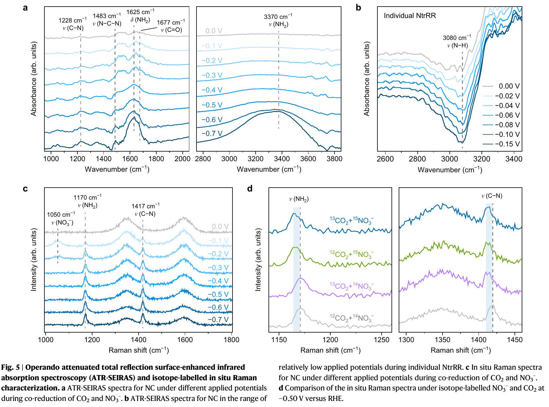
Operando attenuated total reflection surface-enhanced infrared absorption spectroscopy (ATR-SEIRAS) can provide critical details to better understand the and co-reduction mechanism on NC catalyst. Figure 5a shows the ATR-SEIRAS spectra with applied potentials varying from 0 to -0.7 V versus RHE, where several infrared bands are detected in the wavenumber ranges of 1000-2000 and . Two bands at around 1625 and could be
assigned to the bending and stretching (including symmetrical and antisymmetrical components) modes of , respectively , both of which show a marked increase in intensity from -0.5 to -0.7 V . This is consistent with the surge in production of at voltages approaching -0.7 V as revealed in electrochemical experiments. The bands centred at around 1483 and correspond to the antisymmetrical stretching vibration of urea and the stretching vibration of the reaction intermediates, respectively , while the stretching mode of is also observed at . Their intensity steadily grows at voltages from 0 to -0.5 V and is modestly evolving afterwards, which reflects the successful coupling and the production of urea at this voltage range during the coreduction of and .
To elucidate the changes in catalytic centre on NC during the reduction reactions, we investigate the evolution of species in individual NtrRR by means of operando ATR-SEIRAS. To minimize the influence from products, the potential is scanned from 0 to -0.15 V ; at more negative voltages the formation of will be initiated. We stress that while positive peaks in an ATR-SEIRAS spectrum represent an increase in concentration of the corresponding species at or near the surface, negative peaks can be ascribed to a decrease in concentration of the existing species. As shown in Fig. 5b, a negative peak appears at that is attributed to stretching vibration , and its intensity is enhanced at more cathodic potentials. This suggests that the protons on existing species at NC catalyst are diminishing at an initial stage of NtrRR, consistent with previous studies demonstrating the easy cleavage of bonds on . Therefore, we can infer that the NtrRR process directly consumes the protons on species. Such a change in the catalytic centre is expected to produce an alteration in activity, thus creating the opportunity to switch the reaction path to and enable the sequential mechanism for and co-reduction to urea. After the formation of urea, the high thermodynamic driving force as mentioned above ( ) could trigger rehydrogenation of NC , and the -H species can serve as dynamically evolving active centres in the coreduction reaction. We note that this depletion feature is barely discernible on in operando ATR-SEIRAS (Supplementary Figs. 39 and 40).
In situ Raman spectroscopy was also conducted to monitor the surface species during the catalytic reaction. As shown in Fig. 5c, a peak at corresponding to the symmetrical stretching mode of nitrate ion is observed. The peaks that appeared at 1170 and could be assigned to the stretching vibration of and , respectively , indicating their formation in the co-reduction of and -isotope and -isotope-labelled experiments (Fig. 5d) were performed under an applied potential of -0.5 V versus RHE with and as the electrolyte and feeding gas. The positions of D and G bands of NC remain unchanged regardless of the isotope used. The Raman peak of band shows a red shift in isotope substitution experiments, and the peaks of are evidently shifted to lower values as compared to . These results verify that both nitrogen and carbon sources of urea originate from the employed feedstocks rather than from the functional groups on NC catalyst.
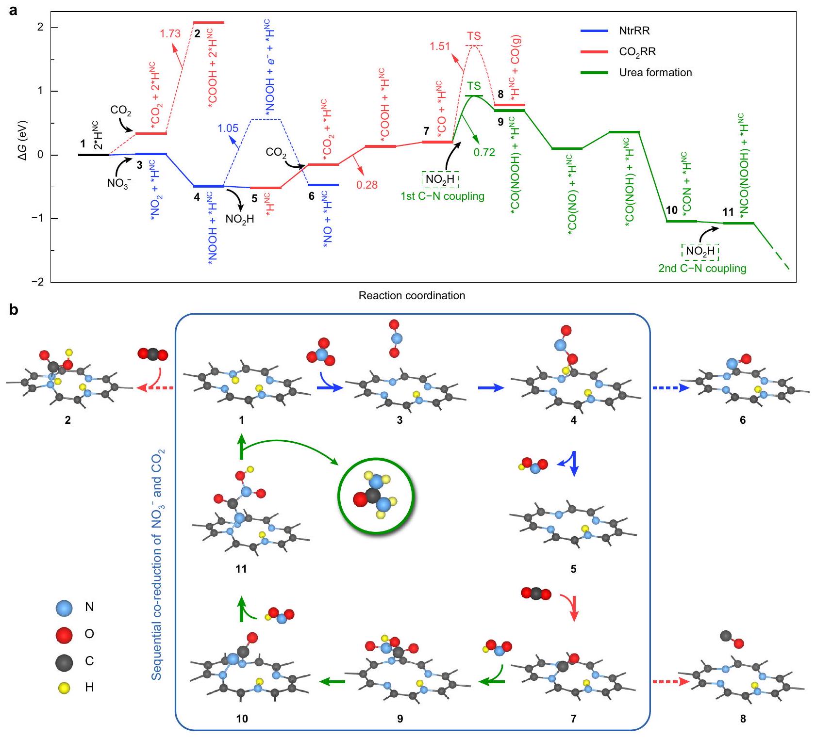
Fig. 6 | Proposed reaction path of the sequential co-reduction reaction on NC. a The DFT-calculated Gibbs free energy profile of the co-reduction reaction of and at 0 V versus RHE. Elementary steps marked by dashed lines are less favourable than those marked by solid lines. The transition states (TS) of *CO
desorption ( ) and coupling ( ) were obtained by CI-NEB calculations. b Structural configurations of the critical reaction intermediates. Intermediates in the frame are related to the sequential co-reduction mechanism leading to urea formation.
DFT calculations of sequential reduction mechanism
Leveraging DFT Gibbs free-energy calculations, we can address the reaction pathway of urea electrosynthesis on the NC catalyst, which lends strong support to the sequential reduction scenario. Hydrogenated pyridinic site with two bonded H atoms (configuration 1 in Fig. 6, denoted as ) was taken as the representative catalytic centre. At the beginning, NtrRR will readily take place while is disfavoured because of the significant barrier to form * COOH (2). Although can be reduced into * in an electrochemical step , this conversion can also occur via proton-coupled electron transfer from the catalyst . In other words, derives a protonelectron pair from the dehydrogenation of the site, thus leaving one on the site and forming a configuration of , which is endothermic by only 0.08 eV . We find that the * intermediate cannot chemically bind to the catalyst, but is in fact trapped by van der Waals forces and located at a distance of around from the catalytic centre (Supplementary Fig. 41). Similarly, *NOOH (4) and *NO (6) are
physically rather than chemically adsorbed to the catalyst. The freestanding nature of these intermediates has led to a low overlap of electronic states between the adsorbed molecules and the catalyst. In particular, an energy gap of 1.05 eV exists between the lowest unoccupied molecular orbital (LUMO) of *NOOH and the Fermi level in configuration 4 (Supplementary Fig. 42). This result indicates that substantial energy is required to inject an electron from the catalyst to the adsorbed *NOOH molecule, thus imposing severe constraints on its electrochemical reduction. In comparison, the desorption process of *NOOH (4) is energetically favourable, exothermic by -0.05 eV , which offers ample opportunity for exposing the site with one atom remaining (5). The easy desorption and migration of found by DFT calculations are in line with the experimental observation that NC catalyst is selective towards formation during individual reduction of .
Subsequently, from configuration 5, the reduced steric effect at the catalytic centre due to a missing is at play to guarantee facile and coupling processes. The steric effect gives rise to a
strong interaction between *COOH and NC catalyst (Supplementary Fig. 43), which is the reason for the remarkable reduction in energy consumption at the step with one as compared to that with two atoms ( 1.73 eV ). The high propensity for at this stage supports our speculation that conversion can be promoted after NtrRR. The next bifurcation of the reaction pathway occurs at *CO, which will undergo either desorption or C-N coupling. Since both steps are kinetics-dominated processes, we here employed climbing-image nudged elastic band (CI-NEB) calculations (Supplementary Fig. 44) to determine their activation barriers. The results show that the barrier for the formation of is substantially higher than that of *CO(NOOH) (9), well matching with the inferior selectivity to CO product in the experiments. Then, the * intermediate undergoes three sequential electrochemical reduction steps and releases two water molecules to form *CON (10), at which the second coupling takes place utilizing another nearby. The resultant intermediate *NCO(NOOH) (11) will undergo reduction into urea, and all the elementary steps in between are thermodynamically spontaneous (Supplementary Fig. 45) except for the *NCO(NO) * step ( 0.34 eV ). After the urea molecule leaves the catalyst surface, the site will be hydrogenated immediately, leading to the regeneration of the configuration (Supplementary Fig. 17).
Collectively, the DFT results in Fig. 6 provide us with a comprehensive picture of the sequential reduction mechanism on NC. At the core of this mechanism lies the capability of structural alteration of the catalytic centre (between 1 and 5), which is dynamic and reversible in the urea formation process. For comparison, DFT calculations were also performed for . The moiety corresponds to the catalytic centre, which may not undergo hydrogenation due to the saturation of all N atoms. The NtrRR process is initiated by the electrochemical reduction of , followed by further reduction into *NO with a flattened energy landscape (Supplementary Fig. 48). We note that unlike on NC catalyst, all the intermediates on are chemically bonded to the catalytic centre (Supplementary Fig. 49), thus avoiding the exposure of the catalytic centre to other reactants. NtrRR continues to proceed until the formation of is completed, with a limiting potential of 0.31 V . On the other hand, the process is sluggish due to the highly endothermic * * COOH step ( 1.59 eV ), similar to the case of site with two atoms. As the catalyst remains intact throughout the reactions, an equally huge amount of free energy input would be required to activate this step and afford the *CO intermediate, which is indispensable for urea formation. This suggests that is the most accessible product in the co-reduction of and on , showing good agreement with the experimental results. The proposed rationalization may also provide an explanation for the change in product selectivity on : the overall selectivity observed experimentally at -0.7 V is correlated with the competition for catalytic centres between NtrRR and , while less negative potentials would lead to less fierce competition, and therefore more ample opportunities for concomitant reduction of both reactants.
Discussion
In this work, selective urea electrosynthesis via a sequential reduction process utilizing and as reactants is proposed and demonstrated on an N -doped carbon catalyst. This NC catalyst delivers a urea yield rate of with a high FE of at -0.5 V versus RHE, outperforming most of the previously reported catalysts and showing great potential in large-scale application. In sharp contrast with NC, the single-atom catalyst displays a much lower urea selectivity, which originates from the fierce and constant competition between the reduction of and at a single catalytic centre. Based on rationally designed experiments, operando measurements and DFT calculations, we reveal the essential role of the species
on NC that could serve as dynamic active sites. The reaction preference is inherently controlled by the number of bonds and is switchable between favouring NtrRR process or process, whereby the reduction reactions are sequential and steered towards urea formation. The fundamental understanding of the sequential reaction model can form the basis for furthering the development of selective electrocatalysts to permit facile coupling and efficient synthesis of urea.
Methods
Synthesis of NC and
NC was prepared via a two-step pyrolysis method, using glucose (GC) and dicyandiamide (DCDA) as carbon source and nitrogen source, respectively. GC and DCDA were purchased from Sigma-Aldrich, and were directly used without further treatment. GC was mixed with DCDA at a mass ratio of , and the mixture was sintered under flowing Ar at for 6 h to form . Subsequently, the resultant product was carbonized at for 3 h in an Ar atmosphere. The process of preparing and other single-atom catalysts was the same as that of NC, except for adding the metal precursors such as . Finally, aggregates of metal particles were removed by washing the catalysts thoroughly in .
Ex situ and in situ characterizations
The XRD patterns were collected on a Bruker D8 Advance diffractometer equipped with radiation, scanning from to with a scan rate of . The structure and morphology of the samples were investigated on a field emission scanning electron microscope (ZEISS SUPRA , Carl Zeiss) and a transmission electron microscope (JEM-3200FS, JEOL) equipped with an EDS detector. XPS experiments were conducted on an ESCALAB 250X instrument (Thermo Fisher).
The electrochemical operando ATR-SEIRAS was measured by INVENIO R FTIR spectrometer (Bruker) equipped with a mercury-cadmium-telluride (MCT) detector. electrode and a Pt foil were employed as the reference electrode and the counter electrode, respectively. During spectrum collection, the optical path was continuously purged with nitrogen gas to minimize the disturbance caused by water and in the air. -saturated electrolyte containing and was employed in the coreduction reaction process of and . The background spectrum of the catalyst electrode was obtained at an open-circuit potential before each measurement. Then, the absorbance spectra (- ) at different potentials were collected at a spectral resolution of . In the ATR-SEIRAS spectra, a negative peak indicates that a certain substance or functional group is consumed, while a positive peak indicates that a certain substance or functional group is produced or has increased.
The in situ Raman characterization was performed in a threeelectrode cell equipped with a confocal microscope Raman system (Renishaw inVia). The wavelength was 532 nm with a microscope objective. During the testing process, the distance between the sapphire window and the electrode was less than 0.1 nm , which ensures that the attenuation effect of the solution layer on Raman signal can be as small as possible.
Electrochemical measurement
The electrochemical measurement was conducted on a threeelectrode configuration using a CHI 660E electrochemical station in the H-type cell. Nafion 115 (Dupont) was pretreated and used to assemble the H -type cell. The Nafion membrane was first heated in at for 1 h and rinsed by deionized water. Then, it was further heated in at for 1 h and rinsed by deionized water again. An electrolyte composed of and saturated with was employed, with an
electrode (in saturated KCl ) and a platinum foil ( ) used as the reference electrode and the counter electrode, respectively. 1 mg of catalyst material was dispersed in deionized water, isopropanol and Nafion ( aqueous solution), and then sonicated for 3 h under ice-water bath. Afterwards, of the catalyst ink was loaded onto a carbon paper (Toray, TGP-060) and dried in the ambient environment to form the working electrode (geometric area: ; mass loading: ). Before electrochemical tests, was purged into the electrolyte for 30 min with a flow rate of 100 sccm to remove the residual air. Potentiostatic electrolysis for 30 min with a flow rate of 20 sccm was done at each potential, and the gas products were analysed with a interval by gas chromatography (SHIMADZU, GC-2014C) equipped with a flame ionization detector (FID) and a thermal conductivity detector (TCD). The gas chromatography was calibrated using standard samples under standard conditions ( ). The linear sweep voltammetry test was performed at a scan rate of . The N -selectivity of reaction products was calculated as follows:
where and are the moles of nitrogen for a specific N-containing product and for all products in NtrRR, respectively.
Computational details
All the theoretical calculations were performed via spin-polarized DFT using Vienna ab initio simulation pack (VASP 5.3.5) with projector augmented wave method . The Perdew-Burke-Ernzerhof (PBE) exchange-correlation functional was employed along with a planewave cutoff energy of 450 eV . The third-generation (D3) semiempirical van der Waals corrections proposed by Grimme were adopted in structural optimization to deal with the dispersion interactions. Supercells consisting of unit cells were constructed for the carbon layers of both NC and catalysts, with a vacuum space of to separate the slabs in the direction. The Brillouin zone was sampled by -centred Monkhorst-Pack -point mesh of for free energy calculations. To take into account the contribution of hydrogen bonds, we introduced four water molecules in our simulations for the adsorbate configurations. Each image in the climbing-image nudged elastic band (CI-NEB) calculations was relaxed until a force tolerance of was reached.
Computational hydrogen electrode (CHE) model was employed for Gibbs free energy calculation in every elementary step. In this scheme, the free energy of pair is equivalent to the chemical potential of gaseous at standard conditions ( bar, ). The free energy change of each elementary step can be calculated by the following equation:
where is the total energy directly calculated by DFT; is the zeropoint energy, which was obtained from the calculated vibrational frequencies of the adsorbates using normal mode analysis; is the entropy and was set to room temperature ( 298 K ); is the potential measured against the standard hydrogen electrode; is Boltzmann constant. The entropy for each reaction intermediate was calculated by the following equation:
where and are Planck constant and the vibrational frequencies of the adsorbates, respectively. In this work, the free energy profiles were calculated at 0 V versus RHE and .
Data availability
The data generated or analysed during this study are included in this published article and its supplementary information files, and are available from the corresponding authors on reasonable request. Source Data are provided with this paper.
References
Zhang, X. et al. Managing nitrogen for sustainable development. Nature 528, 51-59 (2015).
Glibert, P. M., Harrison, J., Heil, C. & Seitzinger, S. Escalating worldwide use of urea-a global change contributing to coastal eutrophication. Biogeochemistry 77, 441-463 (2006).
Tang, C. & Qiao, S.-Z. How to explore ambient electrocatalytic nitrogen reduction reliably and insightfully. Chem. Soc. Rev. 48, 3166-3180 (2019).
Zhou, S. et al. Boron nitride nanotubes for ammonia synthesis: activation by filling transition metals. J. Am. Chem. Soc. 142, 308-317 (2019).
Van der Ham, C. J., Koper, M. T. & Hetterscheid, D. G. Challenges in reduction of dinitrogen by proton and electron transfer. Chem. Soc. Rev. 43, 5183-5191 (2014).
Martín, A. J., Shinagawa, T. & Pérez-Ramírez, J. Electrocatalytic reduction of nitrogen: from Haber-Bosch to ammonia artificial leaf. Chem 5, 263-283 (2019).
Shen, H. et al. Electrochemical ammonia synthesis: mechanistic understanding and catalyst design. Chem 7, 1708-1754 (2021).
Ko, B. H., Hasa, B., Shin, H., Zhao, Y. & Jiao, F. Electrochemical reduction of gaseous nitrogen oxides on transition metals at ambient conditions. J. Am. Chem. Soc. 144, 1258-1266 (2022).
Yuan, M. et al. Unveiling electrochemical urea synthesis by coactivation of and with Mott-Schottky heterostructure catalysts. Angew. Chem. Int. Ed. 133, 11005-11013 (2021).
Yuan, M. et al. Electrochemical C-N coupling with perovskite hybrids toward efficient urea synthesis. Chem. Sci. 12, 6048-6058 (2021).
Shi, R. & Zhang, T. Electrochemical urea production directly from and in ambient aqueous media. Sci. China Chem. 63, 1580-1581 (2020).
Ghorai, U. et al. Understanding the site-selective electrocatalytic co-reduction mechanism for green urea synthesis using copper phthalocyanine nanotubes. Adv. Funct. Mater. 32, 2200882 (2022).
Saravanakumar, D., Song, J., Lee, S., Hur, N. H. & Shin, W. Electrocatalytic conversion of carbon dioxide and nitrate ions to urea by a titania-Nafion composite electrode. ChemSusChem 10, 3999-4003 (2017).
Lv, C. et al. Selective electrocatalytic synthesis of urea with nitrate and carbon dioxide. Nat. Sustain. 4, 868-876 (2021).
Meng, N., Huang, Y., Liu, Y., Yu, Y. & Zhang, B. Electrosynthesis of urea from nitrite and over oxygen vacancy-rich ZnO porous nanosheets. Cell Rep. Phys. Sci. 2, 100378 (2021).
Cao, N. et al. Oxygen vacancies enhanced cooperative electrocatalytic reduction of carbon dioxide and nitrite ions to urea. J. Colloid Interface Sci. 577, 109-114 (2020).
Rooney, C. L., Wu, Y., Tao, Z. & Wang, H. Electrochemical reductive N -methylation with enabled by a molecular catalyst. J. Am. Chem. Soc. 143, 19983-19991 (2021).
Chen, C. et al. Coupling and in to synthesize urea under ambient conditions. Nat. Chem. 12, 717-724 (2020).
Huang, Y. et al. Direct electrosynthesis of urea from carbon dioxide and nitric oxide. ACS Energy Lett. 7, 284-291 (2021).
Jouny, M. et al. Formation of carbon-nitrogen bonds in carbon monoxide electrolysis. Nat. Chem. 11, 846-851 (2019).
Tao, Z., Rooney, C. L., Liang, Y. & Wang, H. Accessing organonitrogen compounds via coupling in electrocatalytic reduction. J. Am. Chem. Soc. 143, 19630-19642 (2021).
Shibata, M., Yoshida, K. & Furuya, N. Electrochemical synthesis of urea on reduction of carbon dioxide with nitrate and nitrite ions using Cu-loaded gas-diffusion electrode. J. Electroanal. Chem. 387, 143-145 (1995).
Siva, P., Prabu, P., Selvam, M., Karthik, S. & Rajendran, V. Electrocatalytic conversion of carbon dioxide to urea on nano- surface. Ionics 23, 1871-1878 (2017).
Hamme, R. C. & Emerson, S. R. The solubility of neon, nitrogen and argon in distilled water and seawater. Deep-Sea Res. I Oceanogr. Res. Pap. 51, 1517-1528 (2004).
Chen, G.-F. et al. Electrochemical reduction of nitrate to ammonia via direct eight-electron transfer using a copper-molecular solid catalyst. Nat. Energy 5, 605-613 (2020).
Li, J. et al. Efficient ammonia electrosynthesis from nitrate on strained ruthenium nanoclusters. J. Am. Chem. Soc. 142, 7036-7046 (2020).
Chen, J. G. et al. Beyond fossil fuel-driven nitrogen transformations. Science 360, eaar6611 (2018).
Wang, Y., Yu, Y., Jia, R., Zhang, C. & Zhang, B. Electrochemical synthesis of nitric acid from air and ammonia through waste utilization. Natl Sci. Rev. 6, 730-738 (2019).
Wang, R. et al. nanoarrays: an efficient catalyst electrode for nitrite electroreduction toward sensing and synthesis applications. Chem. Comm. 54, 10340-10342 (2018).
Kim, J. E., Choi, S., Balamurugan, M., Jang, J. H. & Nam, K. T. Electrochemical C-N bond formation for sustainable amine synthesis. Trends Chem. 2, 1004-1019 (2020).
Yang, H. et al. Scalable production of efficient single-atom copper decorated carbon membranes for electroreduction to methanol. J. Am. Chem. Soc. 141, 12717-12723 (2019).
Cai, Y. et al. Insights on forming N, O-coordinated Cu single-atom catalysts for electrochemical reduction to methane. Nat. Commun. 12, 1-9 (2021).
Chen, S. et al. Boosting -to- CO conversion on a robust singleatom copper decorated carbon catalyst by enhancing intermediate binding strength. J. Mater. Chem. A 9, 1705-1712 (2021).
Yang, F. et al. Scalable strategy to fabricate single Cu atoms coordinated carbons for efficient electroreduction of to CO . Carbon 168, 528-535 (2020).
Zhu, T. et al. Single-atom Cu catalysts for enhanced electrocatalytic nitrate reduction with significant alleviation of nitrite production. Small 16, 2004526 (2020).
Tian, K. et al. Single-site pyrrolic-nitrogen-doped sp2-hybridized carbon materials and their pseudocapacitance. Nat. Commun. 11, 1-10 (2020).
Song, Y. et al. Nitrogen-doped ordered mesoporous carbon with a high surface area, synthesized through organic-inorganic coassembly, and its application in supercapacitors. ChemPhysChem 15, 2084-2093 (2014).
Matanovic, I. et al. Core level shifts of hydrogenated pyridinic and pyrrolic nitrogen in the nitrogen-containing graphene-based electrocatalysts: in-plane vs edge defects. J. Phys. Chem. C. 120, 29225-29232 (2016).
Jia, C. et al. Nitrogen vacancy induced coordinative reconstruction of single-atom Ni catalyst for efficient electrochemical reduction. Adv. Funct. Mater. 31, 2107072 (2021).
Wang, A., Li, J. & Zhang, T. Heterogeneous single-atom catalysis. Nat. Rev. Chem. 2, 65-81 (2018).
Beniya, A. & Higashi, S. Towards dense single-atom catalysts for future automotive applications. Nat. Catal. 2, 590-602 (2019).
Xu, C. et al. Highly selective two-electron electrocatalytic reduction on single-atom Cu catalysts. Small Struct. 2, 2000058 (2021).
Li, X. H., Kurasch, S., Kaiser, U. & Antonietti, M. Synthesis of monolayer-patched graphene from glucose. Angew. Chem. Int. Ed. 51, 9689-9692 (2012).
Wang, Y., Wang, D. & Li, Y. Rational design of single-stom site electrocatalysts: from theoretical understandings to practical applications. Adv. Mater. 33, 2008151 (2021).
Li, Y. et al. Atomically dispersed metal dimer species with selective catalytic activity for nitrogen electrochemical reduction. J. Mater. Chem. A 7, 22242-22247 (2019).
Lautié, A., Froment, F. & Novak, A. Relationship between NH stretching frequencies and N… O distances of crystals containing NH… O hydrogen bonds. Spectrosc. Lett. 9, 289-299 (1976).
Yang, H. B. et al. Atomically dispersed Ni (I) as the active site for electrochemical reduction. Nat. Energy 3, 140-147 (2018).
Kabir, S., Artyushkova, K., Serov, A., Kiefer, B. & Atanassov, P. Binding energy shifts for nitrogen-containing graphene-based electrocatalysts-experiments and DFT calculations. Surf. Interface Anal. 48, 293-300 (2016).
Hai, X. et al. Scalable two-step annealing method for preparing ultra-high-density single-atom catalyst libraries. Nat. Nanotechnol. 17, 174-181 (2022).
Wang, X. et al. A directional synthesis for topological defect in carbon. Chem 6, 2009-2023 (2020).
Wu, Y., Ge, L., Veksha, A. & Lisak, G. Cobalt and nitrogen co-doped porous carbon/carbon nanotube hybrids anchored with nickel nanoparticles as high-performance electrocatalysts for oxygen reduction reactions. Nanoscale 12, 13028-13033 (2020).
Xie, W. et al. NiSn atomic pair on an integrated electrode for synergistic electrocatalytic reduction. Angew. Chem. Int. Ed. 133, 7458-7464 (2021).
Qu, Y. et al. Direct transformation of bulk copper into copper single sites via emitting and trapping of atoms. Nat. Catal. 1, 781-786 (2018).
Luo, J., Jiang, L., Ruan, G., Li, C. & Du, F. Fabrication and application of a MIL-68 (In)- incorporated high internal phase emulsion polymeric monolith as a solid phase extraction adsorbent in triazine herbicide residue analysis. RSC Adv. 11, 20439-20445 (2021).
Sheel, A. & Pant, D. Thiourea Bacillus combination for gold leaching from waste lithium-ion batteries. Bioresour. Technol. 15, 100789 (2021).
Xu, F. et al. Ultrafast universal fabrication of metal-organic complex nanosheets by joule heating engineering. Small Methods 6, 2101212 (2022).
Pérez-Gallent, E., Figueiredo, M. C., Calle-Vallejo, F. & Koper, M. T. Spectroscopic observation of a hydrogenated CO dimer intermediate during CO reduction on Cu (100) electrodes. Angew. Chem., Int. Ed. 129, 3675-3678 (2017).
Rijs, A. M. et al. Controlled hydrogen-bond breaking in a rotaxane by discrete solvation. Angew. Chem., Int. Ed. 122, 3988-3992 (2010).
Yadav, S. et al. Polydopamine decorated nanosheet based electrochemical immunosensor for sensitive detection of SARS-CoV-2 nucleocapsid protein in clinical samples. J. Mater. Chem. B 10, 8478-8489 (2022).
Paluszkiewicz, C. et al. Saliva as a first-line diagnostic tool: a spectral challenge for identification of cancer biomarkers. J. Mol. Liq. 307, 112961 (2020).
Spoerke, E. D. & Stupp, S. I. Synthesis of a poly (L-lysine)-calcium phosphate hybrid on titanium surfaces for enhanced bioactivity. Biomaterials 26, 5120-5129 (2005).
Blout, E. R. & Linsley, S. G. Infrared spectra and the structure of glycine and leucine peptides1. J. Am. Chem. Soc. 74, 1946-1951 (1952).
Frost, R. L., Erickson, K. L., Weier, M. L., Leverett, P. & Williams, P. A. Raman spectroscopy of likasite at 298 and 77 K. Spectrochim. Acta A 61, 607-612 (2005).
Feng, X. et al. Niobium oxide promoted with alkali metal nitrates for soot particulate combustion: elucidating the vital role of active surface nitrate groups. Phys. Chem. Chem. Phys. 24, 3250-3258 (2022).
Khan, K. M., Krishna, H., Majumder, S. K. & Gupta, P. K. Detection of urea adulteration in milk using near-infrared Raman spectroscopy. Food Anal. Methods 8, 93-102 (2015).
Barker, I., Fawcett, V. & Long, D. Solvent dependence of the resonance Raman spectra of azobenzene, 4-aminoazobenzene, 4methylaminobenzene and 4-dimethylaminoazobenzene. J. Raman Spectrosc. 18, 71-75 (1987).
Henkelman, G., Uberuaga, B. P. & Jónsson, H. A climbing image nudged elastic band method for finding saddle points and minimum energy paths. J. Chem. Phys. 113, 9901-9904, https://doi.org/ 10.1063/1.1329672 (2000).
Kresse, G. & Joubert, D. From ultrasoft pseudopotentials to the projector augmented-wave method. Phys. Rev. B. 59, 1758 (1999).
Grimme, S., Antony, J., Ehrlich, S. & Krieg, H. A consistent and accurate ab initio parametrization of density functional dispersion correction (DFT-D) for the 94 elements H-Pu. J. Chem. Phys. 132, 154104 (2010).
Nørskov, J. K. et al. Origin of the overpotential for oxygen reduction at a fuel-cell cathode. J. Phys. Chem. B 108, 17886-17892 (2004).
Geng, J. et al. Ambient electrosynthesis of urea with nitrate and carbon dioxide over Iron-based dual-sites. Angew. Chem. Int. Ed. 62, e202210958 (2023).
Lv, C. et al. A defect engineered electrocatalyst that promotes highefficiency urea synthesis under ambient conditions. ACS Nano 16, 8213-8222 (2022).
Liu, X. et al. Carbon nanotubes with fluorine-rich surface as metalfree electrocatalyst for effective synthesis of urea from nitrate and . Appl. Catal. B: Environ. 316, 121618 (2022).
Liu, Y. et al. C-bound or O-bound surface: which one boosts electrocatalytic urea synthesis? Angew. Chem. Int. Ed. 62, e202300387 (2023).
Li, N. et al. Metalphthalocyanine frameworks grown on TiO2 nanotubes for synergistically and efficiently electrocatalyzing urea production from and nitrate. Sci. China Chem. 66, 1417-1424 (2023).
Mao, Y. et al. Ambient electrocatalytic synthesis of urea by coreduction of NO3- and CO2 over graphene-supported . Chin. Chem. Lett. 143, 108540 (2023).
Wang, H. et al. Realizing efficient CN coupling via electrochemical co-reduction of and -on AuPd nanoalloy to form urea: Key CN coupling intermediates. Appl. Catal. B Environ. 318, 121819 (2022).
Acknowledgements
The authors acknowledge financial support from the Guangdong Basic and Applied Basic Research Foundation (2020A1515110843 and 2023A1515011391), the National Natural Science Foundation of China (22109003, 22308322 and 52373223), the Natural Science Foundation of Shenzhen (JCYJ20190813110605381), R&D Project of State Grid Corporation of China (No. 5108-202218280A-2-439-XG), Sichuan Science and Technology Program (2023NSFSC0434) and the Major Science and
Technology Infrastructure Project of Material Genome Big-science Facilities Platform supported by Municipal Development and Reform Commission of Shenzhen.
Author contributions
Yang Li and S.L. conceived the idea and designed the experiments. Yang Li, H.L. and Q.X. synthesized all the materials and conducted the electrochemical tests. M.H. carried out the operando measurements. S.Z. conducted the density functional theory calculations. H.L., Haocong Yi, Haibin Yang, Z.M., Q.Z., Z.W.Y. and W.L. supported the characterizations and analysis. S.L. supervised the research. Yang Li, M.H. and S.L. wrote the manuscript with advice from Yuan Lin, S.X.D. and F.P. All authors participated in the discussion and agreed with the conclusions of the study.
Correspondence and requests for materials should be addressed to Ming Huang or Shunning Li.
Peer review information Nature Communications thanks the anonymous, reviewers for their contribution to the peer review of this work. A peer review file is available.
School of Advanced Materials, Peking University, Shenzhen Graduate School, Shenzhen, Guangdong 518055, China. Hydrogen Energy Institute, Zhejiang University, Hangzhou, Zhejiang 310027, China. Institute of Fundamental and Frontier Sciences, University of Electronic Science and Technology of China, Chengdu 611731, China. Institute of Chemistry, Chinese Academy of Sciences, Beijing 100190, China. Institute for Superconducting and Electronic Materials, University of Wollongong, Wollongong, NSW 2522, Australia. These authors contributed equally: Yang Li, Shisheng Zheng.