الاستقطاب بمساعدة الإلكتروليت مما يؤدي إلى تعزيز فصل الشحنات وكفاءة تحويل الطاقة الشمسية إلى هيدروجين من تحلل مياه البحر Electrolyte-assisted polarization leading to enhanced charge separation and solar-to-hydrogen conversion efficiency of seawater splitting
لقد جذب التحليل الضوئي للماء البحري لإنتاج الهيدروجين اهتمامًا كبيرًا في السنوات الأخيرة. ومع ذلك، فإن كفاءة تحويل الطاقة المنخفضة واستقرار المحفزات الضوئية في بيئة مالحة قد أعاقا بشكل كبير التطبيقات المستقبلية لهذه التقنية. علاوة على ذلك، لا تزال تأثيرات الإلكتروليتات في ماء البحر مثار جدل. هنا نقدم استقطاب الشحنة بمساعدة الإلكتروليت على مادة مدمجة بالنيتروجينالمحفز الضوئي، الذي يوضح التطور المولي لـ و من التحليل الضوئي التحفيزي المدعوم بالحرارة لانقسام مياه البحر. تُظهر دراساتنا الشاملة والتحليلات الحاسوبية أن الأنواع الأيونية في مياه البحر يمكن أن تمتص بشكل انتقائي على الوجوه المستقطبة ضوئيًا ذات الشحنة المعاكسة، مما يمكن أن يطيل عمر حاملات الشحنة بمقدار خمسة أضعاف، مما يؤدي إلى كفاءة تحويل طاقة كلية تبلغفي. باستخدام فرن مركز بالضوء، تم تحقيق معدل ثابت لتطور الهيدروجينيتم إثبات ذلك، وهو من نفس رتبة الحجم مثل المحللات الكهربائية على نطاق المختبر.
تُعتبر تفاعل التحليل الكلي للماء الضوئي الحفزي (POWS) باستخدام المحفزات الجسيمية نهجًا واعدًا لإنتاج الهيدروجين الشمسي، لكن أداؤه محدود بشكل كبير بسبب إعادة اتحاد حوامل الشحنة المولدة ضوئيًا بسرعة، مما يحد عمومًا من كفاءة تحويل الطاقة الشمسية إلى هيدروجين المحققة.) إلى أقل من 5% (المراجع 1-3). من خلال تخفيف خطوة تحديد المعدل لتجديد فراغات الأكسجين عند درجات حرارة مرتفعة، أظهرنا سابقًا أن الحقل الكهربائي المحلي (LEF) أو الحقل المغناطيسي المحلي يمكن أن يعزز تفاعل POWS من خلال تسهيل فصل الشحنات، مما يؤدي إلى تحسين ملحوظ في الأداء.مؤخرًا، تم توجيه اهتمام متزايد إلى تفاعل انقسام الماء باستخدام ماء البحر ، أكثر من من موارد المياه على سطح الأرض موجودة في البحار والمحيطات، ناهيك عن أن إمدادات المياه العذبة قد نفدت بالفعل في جميع أنحاء العالم ، وإزالة ملوحة مياه البحر تؤدي بشكل كبير إلى زيادة التكاليف الرأسمالية الإجمالية. على الرغم من أن التحليل الكهربائي المباشر لمياه البحر قد حقق تقدمًا كبيرًا في السنوات الأخيرة، إلا أن هناك تحديات رئيسية لم يتم التغلب عليها بعد. على سبيل المثال، استخدام مياه البحر يؤثر سلبًا على كفاءة واستقرار أجهزة التحليل الكهربائي، ويزيد استهلاك الكهرباء من تكلفة المستخرج من التحليل الكهربائي لمياه البحر. على النقيض تمامًا، يمكن التغلب على مثل هذه التحديات من خلال التحليل الضوئي للماء البحري باستخدام محفزات ضوئية قوية ذات نطاقات مصممة بعقلانية
المواقع التي يتم فيها توفير الطاقة بواسطة ضوء الشمس الحر. ومع ذلك، في العدد المحدود من أنظمة تحلل مياه البحر الضوئية التي تم الإبلاغ عنها حتى الآن، فإن استخدام المواد التضحوية ضروري، وهو أمر غير مستدام ويؤدي إلى توليد منتجات ثانوية تحتوي على الكربون.. كما أن الأنواع الأيونية في مياه البحر تعقد آلية التحفيز الضوئي. لقد أظهرت بعض المحاولات المبكرة لتقسيم مياه البحر بالتحفيز الضوئي التأثيرات السلبية لمياه البحر على أداء التحفيز الضوئيعلى سبيل المثال، أظهر تيان وزملاؤه أن الصفائح النانوية القائمة على الفوسفور الأسود تقوم بتقسيم مياه البحر بمعدل أقل بكثير مقارنة بالمياه النقية بسبب تمرّد الصفائح النانوية بواسطة الأنواع الأيونية.. ومع ذلك، على العكس من ذلك، فقد تم الإبلاغ مؤخرًا عن وجود يمكن للأيونات أن تسهل حركية التفاعل، مما يؤدي إلى تحسين النشاط التحفيزي الضوئيمن الواضح أن هناك آراء متضاربة بشأن تأثير مياه البحر في هذا المجال البحثي، لذا يجب توضيح دور هذه الأيونات في مياه البحر وتفاعلاتها مع جزيئات المحفز بشكل لا لبس فيه.
في هذه المقالة نُظهر أن الماء ذو المحتوى العالي من الملح يمكن أن يعزز بشكل كبير أداء POWS المعزز بالحرارة على محفز ضوئي من ثاني أكسيد التيتانيوم المدوَّن بالنيتروجين والمُستقطب بشحنة الوجه القوية.) عند من خلال الاستقطاب بمساعدة الإلكتروليت، مع عرض تطور مستمر لـ و بنسبة المولات دون إنتاج أي نواتج ثانوية (مثل و ). تم تحسين النشاط التحفيزي الضوئي بمقدار أربعة أضعاف، وتم تعزيز الكفاءة الكمومية الداخلية (IQE) من 575 إلى 850 نانومتر بمقدار ستة أضعاف في مياه البحر الميت الصناعية، مقارنة بالماء النقي. وبناءً عليه، تم تحقيق كفاءة عاليةمن وكفاءة تحويل طاقة كلية تبلغ تحقق ذلك في نظام تحلل مياه البحر الضوئي المعزز بالحرارة الخالي من عوامل التفاعل التضحية. عاليمعدل التطور لـ ( ) يتم توضيحه في فرن مركز للضوء، والذي يكون من نفس رتبة الحجم كما في المحللات الكهربائية على نطاق المختبر. كما تم توضيح تأثيرات الأنواع الأيونية في مياه البحر: حيث تهاجر الإلكترونات والفجوات المتولدة ضوئياً بشكل انتقائي إلى الوجوه البلورية (101) و(001) عند الإثارة الضوئية. وهذا يؤدي بعد ذلك إلى الامتزاز الانتقائي للأيونات ذات الشحنة المعاكسة. الأيونات الممتزة، بدورها، تولد مجالًا كهربائيًا محليًا قويًا دون استخدام أي محفزات للمجال المحلي، مما يطيل عمر حاملات الشحنة. تم دراسة مجموعة واسعة من الأنواع الأيونية، مما أظهر أنه، بخلاف…الأنيونات، الكاتيونات مثلالتي يُعتبر على نطاق واسع أنها خاملة في تحلل مياه البحر الضوئي يمكن أن تمارس أيضًا تأثير استقطاب قوي. تم تقديم دليل مباشر على استقطاب الشحنة بمساعدة الإلكتروليت هذا بمساعدة تقنيات التوصيف المختلفة، بما في ذلك مطيافية التألق الضوئي المحلولة زمنياً (TRPL)، والمجهر الإلكتروني النافذ الماسح ذو الحقل المظلم الحلقي عالي الزاوية (HAADF-STEM)، ومطيافية فوتوالكترون الأشعة السينية تحت الضغط الجوي (AP-XPS)، وحسابات نظرية الدالة الكثافة (DFT)، وغيرها. ونتيجة لذلك، تم تحديد علاقات خطية بين النشاط التحفيزي الضوئي، وعمر حامل الشحنة، وطاقة استقطاب الشحنة بمساعدة الإلكتروليت. يمكن أن يكون استقطاب الشحنة بمساعدة الإلكتروليت تقنية متعددة الاستخدامات لا تقتصر على مياه البحر فقط، بل تنطبق أيضًا على المحاليل المالحة الصناعية أو مياه الصرف.
النتائج
تأثيرات الأنواع الأيونية عند درجات حرارة مرتفعة
متحكم بالوجهتم تصنيع الهياكل النانوية وتوصيفها بشكل شامل (الشكل التوضيحي التكميلي 1 والملاحظة التكميلية 1). لقد أظهرنا أن تفاعل POWS يمكن تعزيزه بشكل كبير عند درجات حرارة مرتفعة، بحيث يمكن دراسة تأثيرات أخرى مثل تأثيرات استقطاب السطح بشكل أفضل تحت هذه الظروف. تتوفر معلومات خلفية إضافية حول التحفيز الضوئي عند درجات حرارة عالية في المراجع 4-6،25 والملاحظة التكميلية 2. تم تقييم نشاط POWS في هذا العمل عند، والذي ثبت أنه درجة الحرارة المثلى لهذا النظام. تم إجراء تجارب تحكم شاملة بدون تعرض للضوء أو تسخين، ومواد غير نشطة ضوئيًا مثل كانوا تم اختباره أيضًا. أظهرت جميع تجارب التحكم هذه أن تفاعل POWS عند درجات حرارة مرتفعة هو بالفعل تفاعل تحفيزي ضوئي وليس مدفوعًا بالحرارة (الجدول التكميلي 1). بالإضافة إلى ذلك، يظهر الأداء التحفيزي الضوئي استجابة خطية لشدة الإشعاع الضوئي (الشكل التكميلي 2). جزيئات البلاتين النانوية (NPs،)) تم تحميلها على كمساعد محفز (تم تقديم تحسينات تحميل المعدن وكميات المحفز في الأشكال التكميلية 3 و4).
تم الكشف عن دور درجة الحرارة المرتفعة في هذا النظام التحفيزي الضوئي وعلاقته بتأثيرات الإلكتروليت من خلال تجارب النظائر (الملاحظة التكميلية 2 والشكل التكملي 5). ومن المعروف على نطاق واسع أن تفاعل تطور الأكسجين (OER) على المحفزات المعدنية المؤكسدة يمكن أن يحفز آلية تطور الممتز السطحي (AEM) و/أو آلية الأكسجين الوسيط في الشبكة البلورية (LOM).. من الواضح، في AEM، السائلهو المصدر الوحيد للأكسجين، بينما في LOM، كلا السائلين والأكسجين الشبكي يوفر مصدر الأكسجين لتفاعل تطهير الأكسجين (OER). في هذه الدراسة استخدمنا كوسط تفاعل بدلاً من الماء منزوع الأيونات العادي(الكميات الدقيقة من و المستخدمة موضحة في الشكل التوضيحي التكميلي 5)، والأكسجين في الـكان الحفاز في الغالب. الطبيعيوفرة النظير لـتم اعتبارهتم إجراء تفاعل POWS عند درجات حرارة مختلفة (تتراوح من 150 إلى)). الأكسجين المتطور (بما في ذلك و ) تم قياسه بدقة باستخدام مطياف الكتلة خلال تفاعل POWS، للحصول علىنسبة المتطور. ثم تم مقارنة هذه النسبة مع نسبة الماء الأصلي المستخدم في التفاعل. من الواضح أنه إذا كان تفاعل تطهير الأكسجين (OER) يحفز آلية تبادل الأنيونات (AEM)، فستكون النسبتان متشابهتين، في حين أن آلية فقدان الأكسجين (LOM) تؤدي إلى انخفاض فيالنسبة لأن في مشارك في تفاعل تطهير الأكسجين (OER). كما هو موضح في الشكل التكميلي 5، عند كل درجة حرارة من 180 إلى، الينخفض النسبة بشكل حاد خلال الساعة الأولى، وخلال هذه الفترة يصبح عمر التشغيل المتبقي (LOM) أكثر أهمية بشكل متزايد. بعد ذلك،النسبة تزداد قليلاً بسبب أكسجين السطح لـيتم استبداله جزئياً بـمن الماء. وأخيرًا، يتم الوصول إلى حالة مستقرة عند، بعد ذلك يبقى النسبة مستقرة (الشكل التوضيحي التكميلي 5ب). أظهرت دراسة تأثير درجات الحرارة المختلفة أنه مع زيادة درجة حرارة التفاعل، الحالة المستقرةينخفض النسبة بشكل حاد، مما يشير إلى زيادة مساهمة LOM في تطور الأكسجين (الشكل التوضيحي التكميلي 5ج). على النقيض من ذلك، عند درجة الحرارة المنخفضة لـ، الالنسبة لا تتغير بشكل واضح طوال تفاعل POWS. تشير جميع النتائج السابقة إلى أن AEM هو المسيطر على تفاعل OER عند درجات الحرارة المنخفضة، ويتم توليده بشكل رئيسي من المادة الممتصةالأنواع في هذه الحالة. تزداد مساهمة آلية الأكسدة المختلطة (LOM) بشكل كبير مع ارتفاع درجة حرارة التفاعل على هذا المادة المؤكسدة المختزلة، مما يؤدي إلى معدل أعلى لتحلل الماء عند درجات حرارة مرتفعة، كما نوقش سابقًا. إذا تم إجراء تفاعل POWS عند درجة حرارة منخفضة (على سبيل المثال، في درجة حرارة الغرفة)، سيكون من الصعب حدوث تفاعل تطهير الأكسجين (OER)، وتكوين شواغر الأكسجين السطحية، وتجديد شواغر الأكسجين بواسطة أكسجين الشبكة عبر عملية LOM. وبناءً عليه، تصبح عملية آلية النقل الأنيوني (AEM) البطيئة لتفاعل OER هي المسيطرة وتصبح خطوة تحديد المعدل. ونتيجة لذلك، لن يكون التأثير الكبير للإلكتروليتات في تعزيز عمر حاملات الشحنة مرئيًا. لذلك، لملاحظة تأثيرات الإلكتروليت، من الضروري إجراء مثل هذا التحفيز الضوئي عند درجات حرارة مرتفعة.
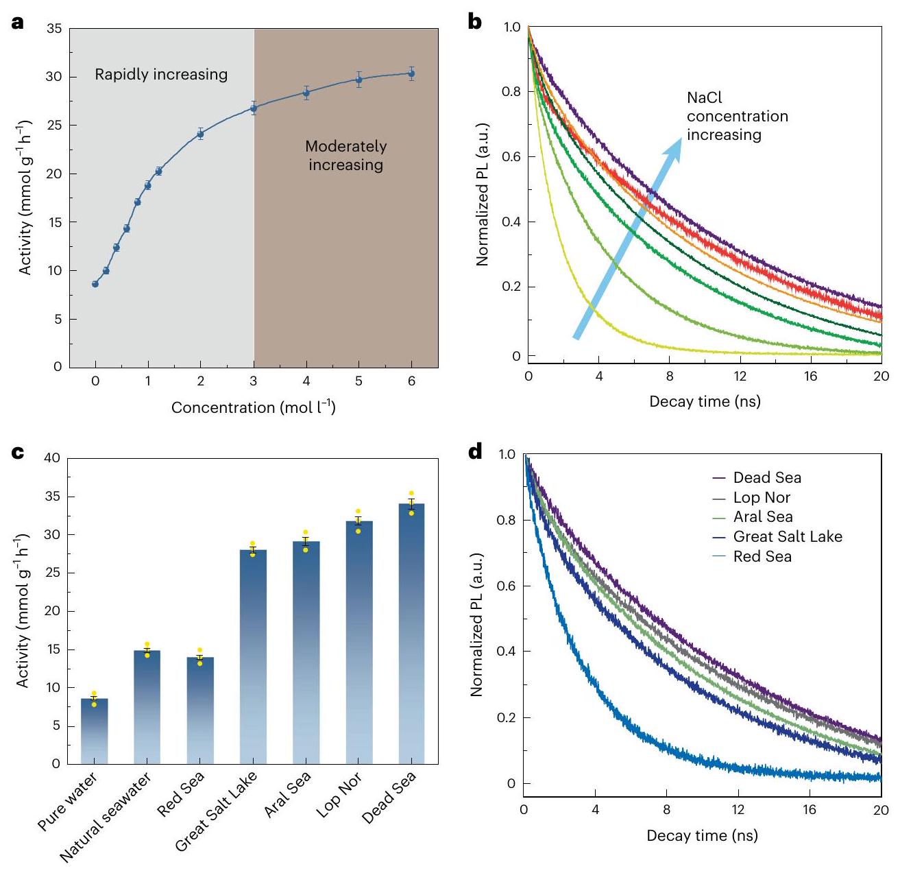
لفهم تأثير الأنواع الأيونية، تم دراسة محاليل NaCl المائية في البداية، ونطاق واسع من التركيزات حتىتم التحقيق في ذلك (الشكل 1أ). تزداد نشاط POWS بشكل متناسب مع تركيز NaCl حتى، مما يظهر تحسناً ملحوظاً من 6.43 إلى ، ثم يصبح التحسين أقل وضوحًا عندما يتم زيادة التركيز أكثر من ذلك. لم نكتشف أي غازالتكوين بعد تفاعل POWS (كما تم تحديده بواسطة كروماتوغرافيا الغاز)، على الأرجح بسبب الجهد المطلوب للأكسدةالأيونات أعلى مما هوحزمة التكافؤ (VB) يمكن أن توفر. أيضًا، إذا يؤكسد إلى، هذا سيؤدي حتمًا إلى زيادة في الرقم الهيدروجيني للمحلول الناتج (المعادلة (3)). لهذا السبب، تم قياس الرقم الهيدروجيني قبل
الشكل 1| اختبارات نشاط POWS وطيف TRPL لـنشاط أسرى الحرب لـتم اختباره في محاليل مائية من NaCl (أ) ومياه البحر الصناعية (ج) عندتم تعريف نشاط أسرى الحرب (POWS) على أنه معدل التطور () لكل وحدة كتلة من المحفز الضوئي، معروضة بوحدات. النقاط البيانية المركزية هي متوسط ثلاث قياسات مستقلة (). تمثل أشرطة الخطأ الانحراف المعياري. تمثل النقاط الصفراء نقاط البيانات. ب، د، TRPL
طيف الـتم اختباره في محاليل مائية من كلوريد الصوديوم عند(التركيزات هي و ، على التوالي، تزداد على طول السهم في ب) (ب) والمياه البحرية الاصطناعية (د). في قياسات TRPL، يتم ضبط الفواصل بين نبضات الليزر المتتالية المقاسة إلىبواسطة منتقي نبضات لضمان أن يكون الفاصل الزمني طويلاً بما يكفي للسماح لحاملات الشحنة المثارة بالاسترخاء الكامل إلى الحالات الأرضية قبل وصول النبضة التالية. وبعد التفاعل، ولم يظهر أي تغيير واضح. باستخدام المعايرة، قمنا أيضًا بتحليل توازن الكلور بعناية قبل وبعد التفاعل. تراكيزقبل وبعد تفاعل أسرى الحرب يتفقان مع بعضهما البعض ضمن عدم اليقين التجريبي، مما يشير إلى أنلا يُستهلك أثناء التفاعل. للكشف عن أي مادة مذابة محتملةو HClO، قمنا بمزيد من التدقيق في محلول ما بعد التفاعل. تم إضافة محلول يوديد البوتاسيوم إلى محلول ما بعد التفاعل، مع النشا كمؤشر (تفاصيل الإجراء موضحة في الطرق). لم يُلاحظ أي تغير في اللون، مما يشير إلى عدم وجود أكسدة قابلة للكشفأو أنواع HClO في المحلول. بالإضافة إلى ذلك، الاستمرارتمت مراقبة التطور بعناية خلال كل تفاعل، مما أظهر أن-إلى-نسبة من:1 طوال الوقت (الشكل التوضيحي التكميلي 6). الـ و معدلات التطور والدقيقة-إلى-النسبة، مع الأخطاء، معروضة في الجدول التكميلي 2. مثل هذه النسبة الكيميائية بين و يشير إلى الطبيعة العامة لتفاعل انقسام الماء، وأكسدة أو يمكن تجاهل التفاعلات الجانبية الأخرى في النظام. يجب التأكيد على أنلم يتم الكشف عنه في الطور الغازي، مما يشير إلى أن المادة المكتشفةيتم توليده من تفاعل POWS بدلاً من كونه تلوثًا من الهواء. غياب الغازيشير أيضًا إلى أن النيتروجين المستقر المخدر في المحفز لا يتأكسد بواسطة الثقوب خلال التفاعل. أظهرت قياسات XPS بعد التفاعل للمحفز وجود نيتروجين محتوى ، والتي تتطابق مع تلك الخاصة بالمحفز الأصلي، قبل التفاعل، ضمن هامش الخطأ التجريبي. يُفترض أن غياب أكسدة النيتروجين يرجع إلى الحركية المواتية لتطور الأكسجين مقارنة بتكوين ثنائي النيتروجين على المحفز القائم على الأكسيد عند درجات حرارة مرتفعة. بعد ذلك، تم دراسة إلكتروليتات أخرى متعادلة الحموضة، والتي أظهرت جميعها أداءً محسنًا في POWS عندمقارنة بالماء النقي (الشكل التوضيحي التكميلي 7 والجدول التكميلي 2). ومع ذلك، تفاوت التحسين بين الإلكتروليتات المختلفة – وسيتم مناقشة ذلك بالتفصيل لاحقًا.
تم استخدام مطيافية TRPL بعد ذلك للتحقيق في فصل حاملي الشحنة المتولدة ضوئيًا في المحفز الضوئي (الشكل 1ب). تم ملاحظة مكونين مختلفين للتحلل في كل حالة عند تركيب أطياف TRPL (الجدول التكميلي 3). يمكن عزو المكون السريع إلى عملية إعادة الاندماج الذاتية لـفي المنطقة الكتلية، التي تتأثر بالكاد بالمحلول المالح. يُظهر مكون التلاشي البطيء ارتباطًا إيجابيًا مع تركيز محلول NaCl، لذا يُنسب إلى تثبيط إعادة تجميع الشحنات بسبب المجال الكهربائي المحلي بالقرب من السطح، الذي تسببه الأنواع الأيونية. جميع ملاءمات TRPL معروضة في الشكل التكميلي 8، ومعلمات الملاءمة موضحة في الجدول التكميلي 3. بالإضافة إلى ذلك، تُعرض دالة استجابة الجهاز (IRF) في الشكل التكميلي 9، والتي تُظهر عرض IRF يبلغ 48 بيكوثانية. عدة
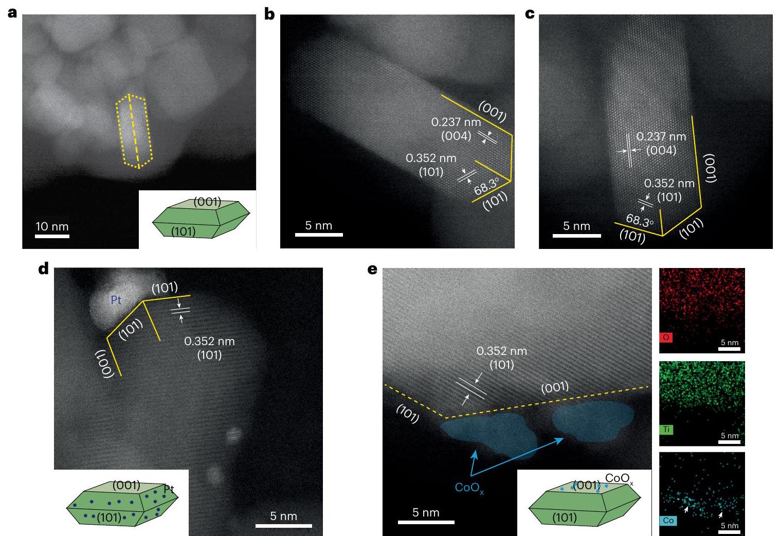
الشكل 2 | الفصل الشحني المعتمد على السطح في الـالمحفز الضوئي. أ-ج، صور HAADF-STEM بتكبير منخفض (أ) وعالي (ب، ج) تُظهر مورفولوجيا. تعرض الصور ذات التكبير العالي أيضًا خطوط الشبكة مع – تباعدات بمقدار 0.237 و0.352 نانومتر، وفقًا لاتجاهات المستويات البلورية [004] و[101] في الأناتاز، على التوالي، تم تحضير مياه البحر لاحقًا لمحاكاة مياه البحر في مناطق مختلفة من العالم (الجدول التكميلي 4). أظهرت مياه البحر الميت، التي كانت تحتوي على أعلى نسبة من الملح، أفضل نشاط تحفيزي ضوئي لـ، تلاها ماء لوب نور، الذي أظهر نشاطًا قدره . مياه البحر الأحمر، التي كانت تحتوي على أدنى تركيز للملح، بما يتوافق مع المتوسط العالمي ()، أعطى نشاطًا أقل نسبيًا منأظهرت دراسات TRPL مرة أخرى أن أعمار حاملي الشحنة تمتد في المياه البحرية الاصطناعية، وتم ملاحظة أطول متوسط عمر لزوج الإلكترون/الثقب يبلغ 10.28 نانوثانية في مياه البحر الميت الاصطناعية (الشكل 1د والجدول التكميلي 3). من الواضح أن الأنواع الأيونية في المحاليل والمياه البحرية الاصطناعية تطيل بشكل كبير عمر حاملي الشحنة المتولدة ضوئياً في الالمحفز الضوئي، وأدى إلى تحسين كبير في الأداء التحفيزي الضوئي. كما تم اختبار مياه البحر الطبيعية لنشاط POWS؛ ومن المثير أن هذا أظهر نشاطًا محسنًا لـ(الشكل 1ج).
آلية فصل الشحنة
الشكل 2أ-ج يعرض صور HAADF-STEM لأناتاز محكم الأوجهالهياكل النانوية. تم تقدير نسب الأسطح المكشوفة (101) و (001) لتكونو60%، على التوالي، وفقًا لبناء وولف. نقطة أوتم تحميلها علىمن خلال الترسيب الضوئي الانتقائي للسطح لمركباتهم القابلة للذوبان من Pt (II) أو Co (II) على التواليلقد تم إثبات أنه عند تعرضه للإشعاع الضوئي، تهاجر الإلكترونات/الثقوب المثارة ضوئياً إلى أسطح جزيئات أشباه الموصلات وتقوم بتقليل/أكسدة المواد الأولية القابلة للذوبان في المحلول، مكونة ترسيباتلذلك، يمكن أن تعمل هذه الجسيمات النانوية كمؤشرات للإلكترونات والفجوات التي تتولد ضوئياً والموجودة على أسطح هذه المحفزات. صور STEM، إلى جانب الطاقة
تحليل التشتت بالأشعة السينية (STEM-EDS)، يظهر بوضوح أنتترسب بشكل مهيمن على الوجوه المكشوفة (001) (الشكل 2هـ والشكل التكميلي 10أ، ب). من ناحية أخرى، يُظهر التحليل الإحصائي أنتُوجد جزيئات Pt النانوية بشكل تفضيلي على الوجوه (101) (الشكل التكميلي 10 والشكل 2د). تُظهر هذه النتائج بوضوح أن الإلكترونات والفجوات الناتجة عن الضوء تُحبس بشكل تفضيلي على الوجوه (101) و(001) لـ، على التوالي. وقد دعمت ذلك أيضًا مواقع حواف النطاق المحسوبة لدينا باستخدام نظرية الوظائف الكثافة للوجهين الاثنين لـ(الشكل التوضيحي التكميلي 11): فرق الطاقة في نطاق التكافؤ هو 1.16 إلكترون فولت وفي نطاق التوصيل هو 0.79 إلكترون فولت، وهذا يمكن أن يسهل بشكل فعال الهجرة غير المتناظرة لحاملي الشحنة نحو الوجوه المختلفة. لذلك، من المتوقع أنوسيتم امتصاص الأيونات بشكل تفضيلي على الوجوه المعنية بواسطة الجاذبيات الكهروستاتيكية، مماثلة للسلوك الذي لوحظ لمركبات البلاتين (II) والكوبالت (II) الأولية.
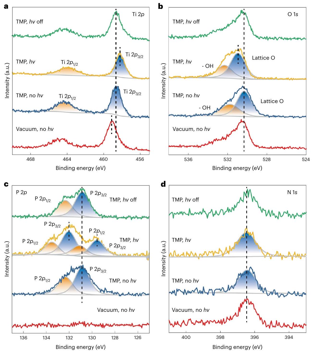
تم إجراء دراسات AP-XPS فيللتحقيق في الخصائص الإلكترونية السطحية لـباستخدام ثلاثي ميثيل الفسفين (TMP) كمسبار سطحي (ملاحظة تكميلية 3). عندما يتم امتصاص TMP على ، الالإشارة تتحول إلى طاقة ارتباط أقل (BE؛ الشكل 3أ)، لأن TMP هو قاعدة لويس، مما يجعل السطحغني بالإلكترونات من خلال تكوين مركبات إضافية، بينمايبقى الإشارة كما هي (الشكل 3ب). تحت إضاءة LED البيضاء، الــينتقل الإشارة قليلاً إلى طاقة ارتباط أقل وإشارة O 1s إلى طاقة ارتباط أعلى (الشكل 3أ، ب، الخطوط الصفراء)، وفقًا للأدبيات، لأن الإلكترونات تتحفز من نطاق التكافؤ الذي يهيمن عليه الأكسجين إلى نطاق التوصيل الذي يهيمن عليه التيتانيوم. تعود هذه التحولات في هذه الإشارات عند إيقاف الضوء، مما يشير إلى أن تحولات طاقة الربط ناتجة عن التحفيز الضوئي وليس بسبب أي تلف في العينة أو إعادة بناء سطحية غير قابلة للعكس. يجب ملاحظة أن التيتانيوموطيف O1s يشمل كل من الإلكترونيات السطحية والداخلية
الشكل 3 | دراسات AP-XPS باستخدام مسبار TMP لـفي. أ-د،(أ)، O1s (ب)،(ج) و(د) الأطياف تحت ظروف مختلفة. تم الحصول على جميع الأطياف عندبدأت القياسات بالحصول على الأطياف تحت الفراغ في الظلام (الخط الأحمر)، ثم تم توجيه بخار TMP بضغط 0.2 مللي بار إلى حجرة القياس وتم الحصول على الأطياف بدون (الخط الأزرق)
الخصائص، نظرًا لعمق أخذ العينات في جهاز XPS الذي يبلغ عدة نانومترات داخل منطقة الكتلة. على النقيض من ذلك، تكشف الأطياف فقط عن ميزات السطح، لأن جزيئات مسبار TMP تمتص فقط على السطح العلوي لجسيم المحفز الضوئي. تم تحديد إشارات مزدوجة فيالطيف، والتي تُنسب إلى و لجزيئات TMP الممتزة على السطح عند غياب الإضاءة (الشكل 3ج). عند الإضاءة، تظهر مجموعتان من قمم الزوج المزدوج من خلال فك التداخل للطيف: مجموعة واحدة تتحول إلى طاقة ارتباط أعلى، والأخرى إلى طاقة ارتباط أقل (الجدول التكميلي 5). مرة أخرى، هذا التغير في طيف N1s يبقى تقريبا كما هو طوال القياسات، مما يشير إلى أن تطعيم النيتروجين مستقر ضد TMP والإضاءة. من الواضح أن النتائج أعلاه تشير بوضوح إلى أن الوجوه (001) تصبح مشحونة إيجابياً تحت الإضاءة بسبب احتجاز الفجوات، مما يؤدي إلى تحول الطيف بالكامل إلى الحالة العكسية عند إزالة الإضاءة (الشكل 3ج، الخط الأخضر).إشارة إلى طاقة ارتباط أعلى؛ على النقيض من ذلك، تلك الممتزة على الوجوه الغنية بالإلكترونات (101) تتحول إلى طاقة ارتباط أقل. يشير التحليل الكمي إلى أن نسبة المساحة لمجموعتي قمم الزوج المزدوج هي، والذي يتطابق مع نسبة الواجهات (101) و(001)، مما يؤكد نسبة الإشارات. تم إجراء تجارب تحكم على مساحيق مع(101) تعرض السطح: لم تشير نتائج AP-XPS إلى أي تأثير ملحوظ لاستقطاب السطح (الشكل التكميلي 12). تم إجراء تجارب AP-XPS مماثلة عند درجات حرارة مختلفة، وأظهرت جميعها نفس ظاهرة استقطاب حاملات الشحنة على السطوح (الشكل التكميلي 13).
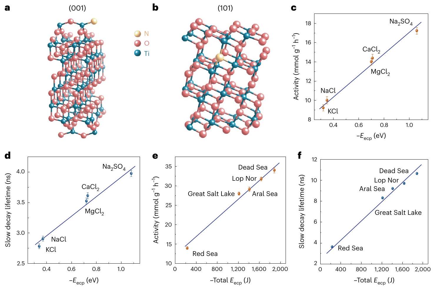
تم إجراء حسابات DFT بعد ذلك لفهم تأثيرات الأنواع الأيونية في مياه البحر. تم توفير الهياكل الإلكترونية لنماذج السطح في الأشكال التكميلية 14-17. لم يتم أخذ تصحيح العزم ثنائي القطب في الاعتبار في الحسابات لأنه له تأثير ضئيل على الطاقة الكلية والجهد الكهروستاتيكي (الشكل التكميلي 18). تم وضع الأنيونات والكاتيونات على الأناتاز المدوَّن بالنيتروجين. ( ) و (101) السطوح (الشكل 4أ، ب)، على التوالي، لدراسة سلوكيات الامتزاز الخاصة بها. قمنا بالتحقيق بشكل منهجي في المواقع المحتملة لامتزاز الأيونات على الـالأسطح. على سبيل المثال، وجدنا أنيفضل الامتزاز في مواقع الجسر بين ذرتي أكسجين متجاورتين على الـالسطح، وطاقات الامتزاز لـعلى هذه المواقع متشابهة تقريبًا.يفضل الامتزاز في الأعلى
الشكل 4 | دراسة حسابية لنظام POWS بمساعدة الإلكتروليت. هياكل الأناتاز المخدوم بالنيتروجين(أ) وأناتاز مخدر بالنيتروجينالأسطح (ب) المستخدمة في حسابات DFT. معلمات الشبكة للأناتازتم تحسينها باستخدام كثيف-متمركز-شبكة نقطية. القيم المحسوبة لمعاملات الشبكة هي و ، بما يتفق جيدًا مع القيم التي تم الحصول عليها تجريبيًا; . تُعرض مزيد من التفاصيل في الجداول التكميلية 6 و7.
ج، د، الارتباطات بين نشاط POWS (ج) وعمر مكون التلاشي البطيء (د) مع الحساباتلأيونات مختلفة. هـ، و، العلاقات بين نشاط POWS (هـ) وعمر مكون التحلل البطيء (و) مع الإجمالي المحسوبلأنواع مختلفة من المياه البحرية الاصطناعية. النقاط المركزية للبيانات هي متوسط ثلاث قياسات مستقلة (). تمثل أشرطة الخطأ الانحراف المعياري. تفاصيل الـتم توفير الحسابات في الجدول التكميلي 8. موقع التيتانيوم رباعي التنسيق في المادة المخدومة بالنيتروجينالسطح (الشكل التوضيحي التكميلي 19). النتائج لـوالامتصاص ينطبق أيضًا على الكاتيونات والأنيونات الأخرى (الأشكال التكميلية 20-25). تم توفير إحداثيات الأنظمة المدروسة كبيانات تكميلية 1. طاقة الامتصاص () يمكن حساب تركيز الإلكتروليت عن طريق جمع طاقات الامتزاز للأنيون والكتيون المقابلين. يتم إضافة الفجوات والإلكترونات إلى نماذج السطح عمدًا لمحاكاة استقطاب الشحنة عند الإثارة. من الواضح أن شدة تأثير استقطاب الشحنة الناتج عن الإلكتروليتات يمكن تقييمها من خلال التغير في الـ من الإلكتروليتات عند الإثارة، والمعرفة هنا على أنها طاقة استقطاب الشحنة بمساعدة الإلكتروليت (). المحسوبتُظهر القيم أن جميع الإلكتروليتات المدروسة يمكن أن تمارس تأثير استقطاب شحني بدرجات مختلفة، اعتمادًا على نصف القطر الأيوني والشحنة، لأن طبيعة هذا التأثير هي التفاعل الكهروستاتيكي بين حاملي الشحنة (الجدول التكميلي 8). طاقات التفاعل الكهروستاتيكي بين الأيونات والمُدخَل النيتروجيني الذي يمكنه احتجاز حاملي الشحنة، أي الإلكترونات على (101) أو الفجوات على (001)-()، تم حسابها. كانت فروق طاقة التفاعل الكهروستاتيكي للأنظمة المشحونة والمحايدة المقابلة جميعها سالبة وتعتمد على حالة التكافؤ للأيونات (الجدول التكميلي 9)، وهو ما يتوافق مع طاقات استقطاب الشحنة الناتجة عن الأيونات المحسوبة (الجدول التكميلي 8). كما قمنا بحساب مخططات فرق كثافة الشحنة لامتصاص الأيونات على المادة المدوّنة بالنيتروجينوالمُشَبع بالنيتروجينالأسطح. تُظهر الرسوم البيانية انتقال الشحنة بين الأيونات والأسطح، ويكون انتقال الشحنة في نظام مشحون عادةً أكثر وضوحًا من ذلك في نظام متعادل الشحنة (الأشكال التكميلية 26-31)، وهو ما يتوافق مع شحنات بادر المحسوبة وفروق كثافة الدوران. تشير كل هذه النتائج بوضوح إلى التفاعل المتبادل الاستقرار بين حاملي الشحنة والأيونات. بعبارة أخرى، يؤدي تأثير استقطاب الشحنة إلى تراكم الكاتيونات والأنيونات على السطوح (101) و(001) على التوالي، وتعمل الأيونات الممتزة بدورها على تعزيز استقطاب الشحنة بشكل أكبر. توضح الشكلين 4ج، 4د أنه مع ازدياد تأثير الاستقطاب (أي، أن تصبح أكثر سلبية)، يتم إطالة عمر حاملي الشحنة بشكل كبير، مما يؤدي إلى تعزيز نشاط POWS، وتُلاحظ علاقات خطية. في حالة المياه البحرية الاصطناعية، يظهر كل من نشاط POWS وعمر حاملي الشحنة، مرة أخرى، علاقات خطية مع(الشكل 4هـ، و). لا شك أن التفاعل القوي بين الأنواع الأيونية والأسطح المستقطبة يلعب دورًا هامًا في نظام POWS لدينا عند درجات الحرارة المرتفعة، مما يسهل احتجاز الشحنات المولدة ضوئيًا على السطح، مما يؤدي إلى إطالة عمر الشحنات (وهو ما تدعمه أيضًا تقنية TRPL في الشكل 1). بالإضافة إلى ذلك، تظهر النشاط علاقة خطية إيجابية مع عمر الشحنات (الشكل 5أ، ب). يسمح العمر الممتد للمزيد من الشحنات بالتفاعل معويروج لـ و التطورات، مما يؤدي إلى تعزيز نشاط أسرى الحرب.
من الواضح أن جميع النتائج المذكورة أعلاه تُظهر أنه في نظام تقسيم مياه البحر لدينا – حيث تكون جزيئات المحفز الضوئي محاطة بالكثير من الأنواع الأيونية – يمكن أن يحدث الامتزاز السطحي الانتقائي للوجه بسهولة بسبب استقطاب الوجه تحت الإضاءة المستمرة. بدوره، تعزز الأنواع الأيونية الممتزة بشكل انتقائي فصل حاملي الشحنة المتولدة ضوئيًا عبر الجذب الكهروستاتيكي، مما يؤدي إلى تحسين أداء تقسيم مياه البحر الضوئي (الشكل 5ج). كما درسنا تأثير امتصاص الأيونات على دالة الشغل ومحاذاة النطاق للمادة المدوّنة بالنيتروجينالأسطح، ووجدنا أن تحلل الماء يمكن أن يتسارع أكثر بعد امتصاص الإلكتروليتات (الأشكال التكميلية 32-35).
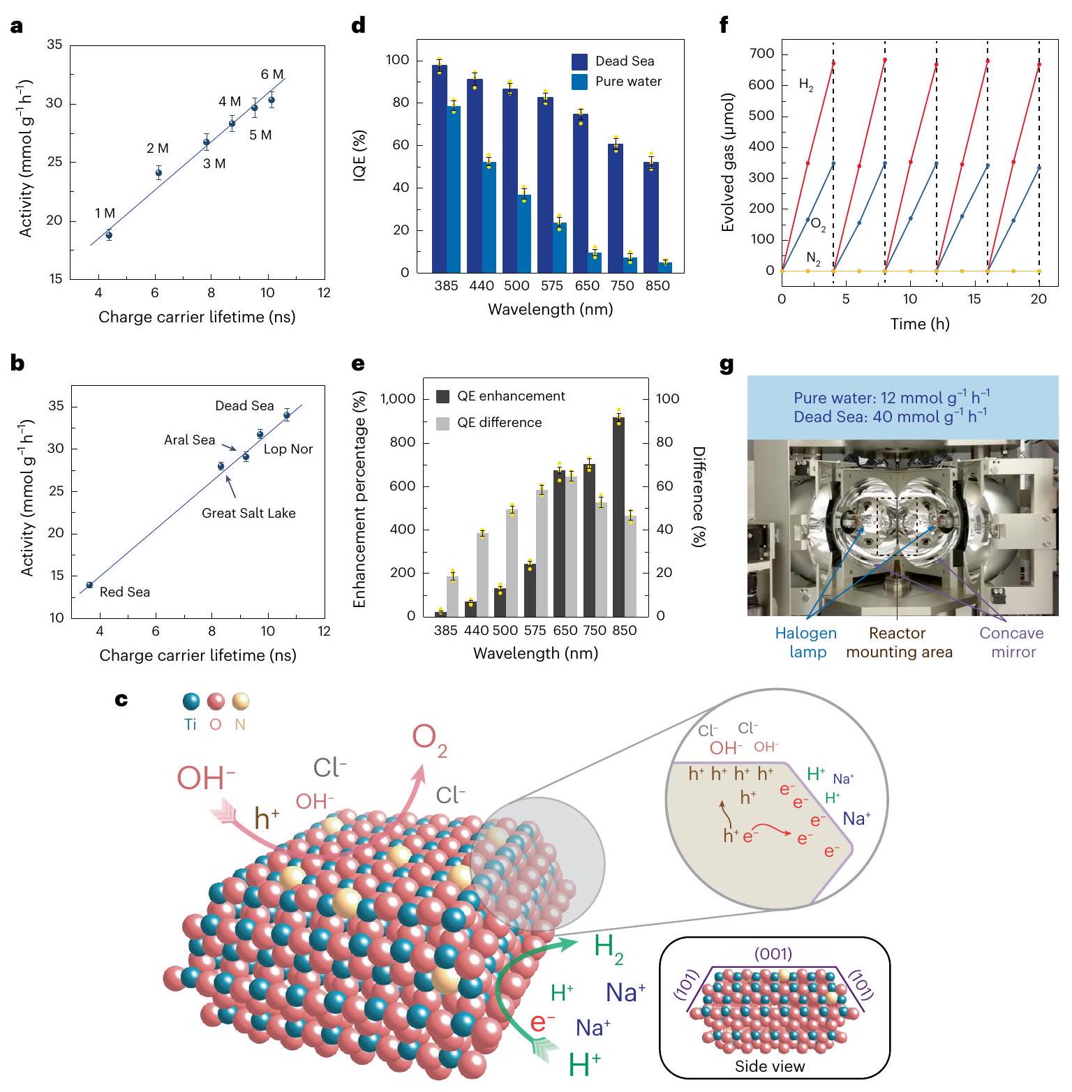
الشكل 5| أداء تفاعل POWS بمساعدة الإلكتروليت. a,b، العلاقة بين نشاط POWS وعمر حاملي الشحنة المتولدة ضوئياً في محاليل NaCl (a) والمياه البحرية الصناعية (b). M تمثل المولارية. c، توضيح تخطيطي لاستقطاب الشحنة بمساعدة الإلكتروليت بين الوجوه المختلفة للوجه المسيطر عليهفي ماء البحر عند الإثارة الضوئية. لم يتم الإشارة إلى إعادة بناء الأسطح (001) من أجل التبسيط، ولكن تم إثباتها بواسطة حسابات DFT. وفقًا لنتائج HAADF-STEM وAP-XPS وDFT، يحدث استقطاب السطح عند الإثارة الضوئية، مما يسهل امتصاص الكاتيونات على الوجوه المكشوفة (101) والأنيونات على الوجوه (001). هذا الامتصاص السطحي المُيسر، بدوره، يجذب الإلكترونات والفجوات بواسطة القوة الكهروستاتيكية، مما يثبط إعادة اتحاد الشحنات ويطيل عمر حاملي الشحنة. د، تقييمات QE لـفي الماء النقي وماء البحر الميت الصناعي عند مستويات مختلفة الأطوال الموجية عند . تشير أشرطة الخطأ إلى الانحراف المعياري. تم تحقيق متوسط كفاءة كمية عالية عبر كامل نطاق الضوء المرئي في ماء البحر الميت الصناعي، دون الانخفاض الحاد النموذجي عند الأطوال الموجية الطويلة. هـ، نسبة تحسين الكفاءة الداخلية الكميةوفارق IQE () لأطوال موجية مختلفة عند ، مشتق من d.f، اختبار استقرار دورة الخمسفي ماء البحر الميت الاصطناعي. ج، فرن مركز للضوء يحاكي فرنًا شمسيًا لتوفير الحرارة والضوء دون إدخال طاقة من أجهزة التدفئة الكهربائية الأخرى، مما يظهر نشاطًا معززًا لـأكثر من 20 ساعة، وهو ما يعادلمعدل التطور لـعند درجة الحرارة والضغط القياسيين، مع العلم أن المنطقة المضاءة كانتوتم استخدام 20 ملغ من المحفز الضوئي في هذه التجربة. في هذا الشكل، تشير جميع أشرطة الخطأ إلى الانحراف المعياري، ونقاط البيانات المركزية لأشرطة الخطأ هي متوسط ثلاث قياسات مستقلة (). النقاط الصفراء تمثل نقاط البيانات.
تقييم الأداء التحفيزي الضوئي
الشكل 5 د يوضح أن كفاءة الكم الداخلي (IQE) لـكما يتم تحسينه بشكل ملحوظ بواسطة تأثير الاستقطاب. يتم الحصول على كفاءة تحويل كمية داخلية عالية في كل من مياه البحر الميت الاصطناعية والمياه النقية عند 385 نانومتر و440 نانومتر، لكنها تنخفض بشكل حاد في المياه النقية عند الأطوال الموجية الأطول من 575 نانومتر إلى 850 نانومتر، وفقًا للتقارير السابقة.. يُعزى هذا التوهين الحاد في كفاءة التحويل الكمي الداخلي إلى توليد أزواج الإلكترون-الثقوب المعتمد على الطول الموجي: قد لا تولد الفوتونات الممتصة عند طول موجي أطول حالة إثارة أزواج الإلكترون-الثقب، بل تثير الانتقالات المحلية. بالإضافة إلى ذلك، يؤدي التحفيز بطول موجي قصير إلى فصل أفضل للشحنات وتقوية التفاعل بين الإلكترون والفونون، في حين أن التحفيز ذو الطول الموجي الطويل يؤدي إلى تعزيز تكوين البولارون المحلي، مما يقلل من حركة حاملات الشحنة وينتج عنه وصول عدد أقل من الحاملات إلى سطح المحفزعند استخدام ماء البحر الاصطناعي، يُلاحظ أن كفاءة الكم الداخلية (IQE) عند الأطوال الموجية القصيرة تتأثر بشكل أقل، لأن عددًا كبيرًا من حاملي الشحنة يمتلك طاقة فائضة جوهرية. يمكن الوصول إلى السطح. ومع ذلك، يمكن الحفاظ على كفاءة الكم الداخلي الأعلى عند الأطوال الموجية الأطول (575-850 نانومتر) بسبب تأثير الاستقطاب الذي تم توضيحه أعلاه والذي تسببه الإلكتروليتات. وبالتالي، فإن كفاءة الكم الداخلي العالية لـ تم تسجيله حتى عند 850 نانومتر (الشكل 5هـ). كما يُظهر أنه لا يوجد فرق كبير في امتصاص الأشعة فوق البنفسجية-المرئية بين الماء النقي ومياه البحر الميت الصناعية (الشكل التوضيحي التكميلي 36). تفاصيل حسابات كفاءة الكم والكفاءة الكمومية الخارجية (EQE) مذكورة في الجدول التكميلي 10 والملاحظة التكملية 4. الـتم تقييمه بعد ذلك، ومنتم تحقيق ذلك من نظام POWS الجسيمي هذا في مياه البحر الميت الاصطناعية عند(الملاحظة التكميلية 4 والجدول التكميلية 11)؛ حسب علمنا، هذا من بين الأفضل المبلغ عنها لأنظمة POWS الجسيمية، ويتجاوز حتى تلك المبلغ عنها للعديد من أنظمة التحليل الكهربائي الضوئي الكهروكيميائي (PEC) وأنظمة التحليل الكهربائي الكهروضوئية (الجدول التكميلية 12). هذا هو أيضًا يتجاوز الهدف بكثير () للتطبيقات العملية لأنظمة POWS التي فرضتها وزارة الطاقة الأمريكية. الـيُظهر المحفز الضوئي تطورًا مستقرًا لـ و ، دون أي انخفاض واضح في النشاط على مدى خمس دورات (الشكل 5f).
قمنا بعد ذلك بتقييم كفاءة تحويل الطاقة الكلية ()، حيث يتم أيضًا أخذ مدخلات الطاقة لتسخين نظام التفاعل في الاعتبار. وهو أمر واعد جدًامنتم إثبات ذلك على مدى 8 ساعات (التفاصيل موضحة في الملاحظة التكميلية 5). على الرغم من أن هذا أقل قليلاً منبعد النظر في مدخلات الطاقة لتسخين والحفاظ على درجة حرارة المفاعل، هذامنلا يزال متفوقًا على جميع القيم التي تم الإبلاغ عنها مؤخرًا في الأدبيات في المجالات ذات الصلة (الجدول التكميلي 12). أيضًا، في تصميم مستقبلي نتوقعه، يمكن توفير الطاقة للتسخين بواسطة ضوء الشمس المركز (الملاحظة التكميلية 2)، بحيث يمكن تقليل استهلاك الطاقة لتسخين الماء والمفاعل أو حتى استبعاده في هذا السيناريو. بالإضافة إلى ذلك، يمكن تغذية البخار المشبع بدرجة حرارة عالية في نظام تدفق إلى مولد توربين بخاري لاسترداد الطاقة. من خلال النظر في جميع هذه التصاميم المحتملة، يمكن تحقيق مستوى أعلىكان من المتوقع.
علاوة على ذلك، حاولنا إثبات الجدوى العملية للتسخين الشمسي المذكور أعلاه. تم استخدام فرن مختبري مكثف للضوء لمحاكاة فرن شمسي (الشكل 5 ج)، مما أظهر نشاط POWS مستقر وفعال عنديمكن الحفاظ عليه فقط بواسطة الضوء المركز دون أي مصادر ضوء أخرى أو أجهزة تسخين. نشاط أكثر استثنائية لـلوحظ ذلك على مدى 20 ساعة بسبب شدة الضوء المركّز العالية. هذه القيمة تعادلمعدل التطور لـعند درجة الحرارة والضغط القياسيين، وهو ما يقارن من حيث الحجم بالقيم المبلغ عنها لأجهزة التحليل الكهربائي القلوية (الجدول التكميلي 12)، لكن نظام POWS الجسيمي هذا هو عملية مباشرة ذات خطوة واحدة لالتقاط الضوء مع جميع مدخلات الطاقة الحرارية والفوتونية القادمة من المكثف الشمسي. تم إجراء تجارب تحكم عن طريق تغطية نوافذ المفاعل بمعجون الكربون لحجب إشعاع الضوء عن تحفيز الفوتوكاتاليست؛ ولم تظهر هذه أي أو التطور، مما يشير إلى أن تفاعل انقسام الماء في الفرن المركز بالضوء هو تفاعل تحفيزي ضوئي، ولا يمكن إتمام هذا التفاعل بدون تعرض للضوء.
مناقشة
باختصار، لقد أظهرنا تقنية سهلة ومتعددة الاستخدامات لاستقطاب الشحنة بمساعدة الإلكتروليت في الماء ذو المحتوى العالي من الملح، مما يسهل فصل حاملي الشحنة المتولدة ضوئياً على واجهات مختلفة من، مما أدى إلى تطور استوكيومتري محسن بشكل كبير لـ و من خلال التحليل الضوئي المساعد بالحرارة لتقسيم الماء بدون مادة تضحيات. تم دراسة استقطاب الشحنة بمساعدة الإلكتروليت باستخدام تقنيات مختلفة، وأظهرت التحليلات الكمية أن كل من أداء التحليل الضوئي وعمر حامل الشحنة يرتبطان خطيًا بطاقة استقطاب الشحنة بمساعدة الإلكتروليت. تم الحصول على الاستقرارالتطور في فرن الشمس على نطاق المختبر يُظهر معدل تطور يبلغلقد حذرت تقييم دورة الحياة الحديثة مخاوف بيئية بشأن التحليل الكهربائي للماء على نطاق واسع إنتاجلذلك، يمكن أن يوفر نظام POWS المباشر ذو الخطوة الواحدة لاستخدام الضوء خيارًا بديلاً. ويُعتقد أن هذه الدراسة تمثل استراتيجية عملية لاستخلاص الطاقة الشمسية من خلال تقسيم مورد المياه المالحة الأكثر وفرة.
الطرق
توليف-مُشَبعالمحفزات الضوئية
توليف التحكم في الواجهةتم اعتماد البلورات النانوية من عملنا السابق من رباعي بوتوكسيد التيتانيوم، ، تم خلطه مع 0.6 مل من حمض الهيدروفلوريك () في أوتوكلاف مبطن بالتفلون ثم تم تسخينه إلىبمعدلوتم الاحتفاظ به لمدة 24 ساعة. تم غسل الراسب الأبيض الناتج بالإيثانول والماء منزوع الأيونات ثلاث مرات على التوالي، ثم جُفف في فرن عند طوال الليل. بالنسبة لتطعيم النيتروجين، 200 ملغ من المادة ذات التحكم في السطح وُضع عادة في قارب من الكوارتز، ثم نُقل إلى فرن أنبوبي. ثم تم تسخين العينة إلىبمعدلوتم الاحتفاظ به لمدة ساعتين تحتالتدفق، وبعد ذلك سُمح له بأن يبرد طبيعياً وتحول إلى مسحوق أزرق داكن من تم جمعه. التم تحميل المحفز الضوئي، ما لم يُذكر خلاف ذلك، (عن طريق طريقة الترسيب الضوئي) بـجسيمات نانوية من البلاتين كـ “مساعد التحفيز لتطور، قبل اختبارات التحفيز الضوئي، كما هو موضح في القسم التالي.
الترسيب الضوئي الانتقائي على الوجه
وتم تحميل جزيئات Pt النانوية على السطح المتحكم فيهمن خلال طريقة الترسيب الضوئي المعتمدة من الأدبياتعادةً، 0.5 جرام من المادة المحضرة أعلاهتم تعليق المسحوق في 80 مل منمحلول (0.01 م)، بعد ذلك كمية معينة منحل () أُضيف إلى المعلق، تلاه التعرض للإشعاع ((مصباح القوس) تحت تحريك قوي لمدة 3 ساعات. تم ترشيح المعلق، غسله بالماء منزوع الأيونات، وأخيرًا تجفيفه عند طوال الليل. لترسيب البلاتين، 0.05 جرام من المادة المحضرة تم تعليق المسحوق في محلول مخلوط من الميثانول (20 مل) والماء (60 مل)، وبعد ذلكحل () أُضيف إلى المعلق تحت تحريك مغناطيسي مستمر، تلاه التعرض للإشعاع (300 واط، مصباح قوس زينون) لمدة 0.5 ساعة. تم ترشيح المعلق، وغسله بالماء المقطر، وأخيرًا تجفيفه عندطوال الليل.
توصيف المواد
تم الحصول على صور STEM-HAADF بدقة ذرية باستخدام نظام S/TEM FEI Titan G2 60-300 المصحح للانحراف الكروي المزدوج عند 300 كيلو فولت مع مسدس انبعاث ميداني. كان زاوية تقارب الشعاع في مجهر الإلكترون Titan 24.5 ملي راديان، وكان النطاق الزاوي لكاشف HAADF من 79.5 ملي راديان إلى 200 ملي راديان. تم الحصول على نتائج رسم خرائط STEM-EDS بواسطة نظام كاشف Bruker Super-EDX 4.
تم إجراء دراسة فصل الشحنة وتوزيعها على السطح بواسطة قياسات AP-XPS باستخدام TMP كمسبار سطحي، في خط شعاع B07 بمصدر الضوء دايموند. تم توزيع العينات المسحوقة في الإيثانول وترسيبها على رقاقة سيليكون، ثم تم تسخينها بواسطة لوحة تسخين عندلإزالة المذيب. تم إجراء القياسات عند درجات حرارة مختلفة تتراوح من 150 إلى. تم إدخال بخار TMP (0.2 مليلتر زئبق) إلى الحجرة التجريبية كمسبار سطحي عند الحاجة. تم الحصول على الأطياف مع وبدون إضاءة LED بالضوء الأبيض () لدراسة تأثير الإثارة الضوئية. التيتانيوم و تم تسجيل الأطياف باستخدام طاقة فوتون ثابتة قدرها 950 إلكترون فولت. ثم تم معايرة طاقة الربط بالنسبة لمستوى فيرمي.
تفاصيل حسابات نظرية الوظائف الكثافة
تم إجراء جميع حسابات DFT المستقطبة للدوران باستخدام حزمة محاكاة فيينا من البداية (VASP).تمت معالجة التبادل الإلكتروني والتأثيرات الترابطية ضمن تقريب التدرج المعمم (GGA) باستخدام دالة بيرديو-بيرك-إرنزرهوف (PBE)طريقة الموجة المعززة بالمجسّات (PAW)بحد قطع طاقة يبلغ
تم استخدام 400 إلكترون فولت لوصف التفاعلات بين الإلكترونات الأساسية والإلكترونات التكافؤية، مع الـ، و تم التعامل مع القشور كإلكترونات التكافؤ. لجميع الحسابات، طبقنا تصحيح التفاعل كولوم الموقع مع قيمة فعالةقيمة 4.2 إلكترون فولت على مدارات التيتانيوم 3d لوصف الحالات الإلكترونية الموضعية بدقة.
الأناتاز المخدر بالنيتروجينوأناتاز المعاد بناؤه والمُشَوب بالنيتروجينتم بناء الأسطح. الأناتاز المضاف إليه النيتروجينتم تمديد السطح كـ () خلية، واللوح احتوى على أربعةطبقات.-تم استخدام شبكة من النقاط للحسابات. الأناتاز المعاد بناؤه والمُطعّم بالنيتروجينتم تمديد السطح كـ () خلية، واللوح احتوى على ثمانيةطبقات.-تم استخدام شبكة من النقاط للحسابات. قمنا بتعيين طبقة فراغية منلتجنب التفاعلات بين الألواح المجاورة. تم تحقيق التقارب في تحسينات الهندسة عندما كانت قوى هيلمان-فاينمان للذرات المسترخية أقل منالطاقات النسبية لأنواع مختلفة من N-المُدخلةوالمُشَبع بالنيتروجين ( ) تم حساب الأسطح ذات المواقع المختلفة للنيتروجين لتحديد موقع التطعيم الأكثر ملاءمة للنيتروجين (الجداول التكميلية 6 و7).
لمحاكاة الأنواع الأيونية والإلكترونات/الثقوب المتولدة ضوئيًا في النظام، تم ضبط معامل NELECT (عدد الإلكترونات) للتحكم في عدد الإلكترونات في مثل هذا النظام. هذه ممارسة شائعة في الأدبيات.. على سبيل المثال، تم حقن إلكترون زائد واحد في النظام لمحاكاة، وتم سحب إلكترون واحد من النظام لمحاكاة. لمحاكاة الأناتاز المخدر بالنيتروجين Nوالأناتاز المعاد بناؤه والمُطعّم بالنيتروجينالأسطح عند الإثارة الضوئية، أي الأناتاز المخدر بالنيتروجينمع الفوتوإلكترونات والأناتاز المعاد بناؤه والمُطعّم بالنيتروجين ( ) مع وجود ثقوب (أي الحالات المشحونة)، قمنا على التوالي بزيادة وتقليل عدد الإلكترونات في الأنظمة بمقدار واحد. تم فحص الشحنات الذرية وفارق كثافة الدوران لكل نظام بعناية لضمان محاكاة الأنواع الأيونية والإلكترونات/الثقوب الضوئية بشكل صحيح (الأشكال التكميلية 14-35).
طاقة الامتزاز () من الإلكتروليتات تم حسابها كما يلي:
أين و هي، على التوالي، الطاقات الكلية المحسوبة للأناتاز المعاد تشكيله والمُطعّم بالنيتروجينلوح السطح مع الأنيون (على سبيل المثال،) يتم امتصاصها على السطح، الأناتاز المعاد تشكيله والمُطعّم بالنيتروجين لوح سطحي مع وضع الأنيون في وسط منطقة الماء في النموذج، الأناتاز المضاف إليه النيتروجينلوح السطح مع الكاتيون (على سبيل المثال،) يتم امتصاصه على السطح، والأناتاز المخدر بالنيتروجين لوح السطح مع وضع الأنيون في وسط منطقة الماء في النموذج. لاحظ أن بيئة الماء تم التعامل معها ضمنيًا باستخدام كود VASPsol مع ثابت عازل مقداره 78.4 (المرجع 59). الجزء الأول على الجانب الأيمن (أي،) هي طاقة الامتزاز لأنيون على الأناتاز المعاد تشكيله والمُطعّم بالنيتروجينالسطح، والجزء الثاني على الجانب الأيمن (أي،) هي طاقة الامتزاز لأيون موجب على الأناتاز المخدر بالنيتروجينالسطح. إذا كان السطحان متعادلين كهربائياً/مشحونين، فإن من الإلكتروليتات قبل وبعد الإثارة (أي، (قبل الإثارة) و(بعد الإثارة) يمكن الحصول عليه.
طاقات استقطاب الشحنة بمساعدة الإلكتروليت () يمكن حسابها كـ
سلبييشير إلى أن تأثير استقطاب الشحنة يزداد بفعل الإلكتروليت.
اختبارات التحفيز الضوئي
تم إجراء تفاعل POWS فيمفاعل دفعي من الفولاذ المقاوم للصدأ مزود بنافذتين من الكوارتز (القطر الداخلي (i.d.) وسمك كل منها). في تجربة نموذجية، تم إضافة 5 ملغ من المحفز إلى 5 مل من محلول مائي (ماء نقي، ماء البحر الصناعي أو ماء البحر الطبيعي) في بطانة من الكوارتز (بطاقة الهويةالقطر الخارجيالارتفاع) تحت التحريك المغناطيسي (750 دورة في الدقيقة)، ثم تم تطهير المفاعل الدفعي بتدفق مستمر من غاز الأرجون لمدة 5 دقائق، بعد إغلاقه جيدًا، لإزالة المذابثم تم ضغط المفاعل الدفعي بغاز الأرجون الخامل بضغط 6 بار. ثم سمح للمفاعل بالارتفاع إلى درجة حرارة مرتفعة معينة مع ضغط بخار ماء مشبع. محاكي شمسي من نوع VeraSol (AM 1.5 G،) تم تطبيقه لتوفير إشعاع شمسي محاكى من خلال نوافذ الكوارتز. تم تبريد المفاعل الدفعي بشكل طبيعي إلى درجة حرارة الغرفة بعد التفاعل، وتم قياس كميات الأكسجين والهيدروجين بواسطة جهاز كروماتوغرافيا الغاز (GC) المزود بكاشفين للتوصيل الحراري (TCDs) مع الهيليوم وكغاز ناقل، على التوالي، لتحقيق حساسية أفضل. كما تم إجراء تحليل GC قبل التفاعلات لضمان أن الهواء والمذابتمت إزالته بالكامل. تم معايرة نظام GC-TCD باستخدام طريقة المعيار الخارجي، بحيث يمكن تحويل مساحة ذروة إشارة GC إلى كمية الغاز باستخدام منحنى المعايرة.
عند إثبات جدوى استخدام الطاقة الشمسية فقط لتوفير كل من التدفئة والإشعاع، فرن ضوئي بمنطقة عائمة بأربعة مرايا (يعمل عندو 1039 W) من شركة Crystal Systems Inc. مزود بأربعة مصابيح هالوجين تم استخدامه لمحاكاة مركز شمسي دون استخدام أي أجهزة تسخين كهربائية. تم إضافة 20 ملغ من المحفز الضوئي إلى 5 مل من ماء ميلي-كيوتحت تحريك مغناطيسي قوي (600 دورة في الدقيقة)، ثم تم وضع نفس المفاعل في الفرن المركز للضوء. تم مراقبة درجة حرارة التفاعل بواسطة مقياس حرارة حراري وتم الحفاظ عليها عندتم قياس المنتجات الغازية بواسطة جهاز كروماتوغرافيا غازية مزود بكاشفات التوصيل الحراري. تم جمع مياه البحر الطبيعية المستخدمة في هذا العمل بالقرب من رصيف بورنماوث (الإحداثيات:) ويُستخدم بعد الترشيح. حيث أن أكسدةالأيونات ستؤدي إلى تغيير في الرقم الهيدروجيني (المعادلات (3) و(4))، لكل تفاعل، تم قياس الرقم الهيدروجيني للمعلق قبل وبعد تفاعل POWS للتأكد من عدم حدوث أي تفاعل جانبي ملحوظ:
تم قياس الكفاءة الكمومية الداخلية (IQE) في نفس المفاعل باتباع نفس الإجراء. المحفز الضوئي الذي يحتوي على 20 ملغ منأُضيف إلى 5 مل من ماء البحر الميت الصناعي تحت تحريك مغناطيسي (600 دورة في الدقيقة)، ثم تم تعريض المفاعل الدفعي للإشعاع بواسطةمصباح Xe (نيو بورت) مزود بمرشحات تمرير النطاق من، و ، على التوالي. بشكل عام، تم تصحيح الفوتونات الساقطة عن طريق طرح الضوء المبعثر والضوء المنقول من الضوء الساقط – تم توفير نافذتين من الكوارتز، متوازيتين، على جانبي المفاعل الدفعي، تواجهان بعضهما البعض. تم قياس الضوء الساقط أولاً باستخدام مقياس ضوء في مركز المفاعل الدفعي، ثم تم قياس الضوء المبعثر والمنقول أيضًا خارج النافذة المقابلة عندما كانت معلق التفاعل موجودًا. بعد ذلك، تم طرح الضوء الخارج من المفاعل من الضوء الساقط، وتم حساب التوهين في شدة الضوء. قد يكون الضوء داخل المفاعل قد تشتت أيضًا بواسطة جزيئات المحفز الضوئي، لكن معظم الضوء كان سينعكس بواسطة سطح الفولاذ المقاوم للصدأ وأخيرًا يمتصه المحفز الضوئي. بعد ذلك، تم حساب عدد الفوتونات الساقطة ذات الصلة من قوى الإشعاع عند كل طول موجي. يمكن حساب الكفاءة الكمومية الداخلية (IQE) وفقًا لـ
تم أيضًا حساب كفاءة الكم الظاهرة (EQE) كما يلي
تم تقديم مثال على حساب QE في الملاحظة التكميلية 4.
التم قياسه بإجراء مماثل. المحفز الضوئي الذي يحتوي على 20 ملغ منأُضيف إلى 5 مل من ماء البحر الميت الاصطناعي تحت تحريك مغناطيسي (600 دورة في الدقيقة)، ثم تم تعريض المعلق للإشعاع بواسطة محاكي شمسي VeraSol (AMالشمس). الـيمكن بعد ذلك حسابها كـ
أينهي قوة الإشعاع الشمسي () ، هي المنطقة المضيئة، و هو وقت التفاعل.
التيسير الكمي وتم تكرار القياسات ثلاث مرات على الأقل، وتم حساب القيم المتوسطة وقيم الانحراف المعياري. أمثلة على كفاءة الكم وتم توفير الحسابات في الملاحظة التكميلية 4.
تقييم كفاءة تحويل الطاقة الكلية
تم تقييم كفاءة تحويل الطاقة الكلية في مفاعل ضوئي مختلف ذو مساحة إضاءة أكبر (نافذة من الياقوت الدائري بنصف قطر 2 سم). ناقشنا مواصفات المفاعل مع المورد (Thoughtventions Unlimited) لضمان كل من السلامة التشغيلية ودقة التجربة. سمح هذا المفاعل بمنطقة إضاءة كبيرة نسبيًا واختراق مناسب للضوء في المعلق المائي. كما تمكنا من تغطية إعداد التجربة بسخان شريطي ومواد عازلة حراريًا، بما في ذلك صوف السيليكا، ورقائق حرارية، وما إلى ذلك، لتقليل فقدان الحرارة. تم تقييم أداء POWS بإضافة 100 ملغ من الـ…إلى 3 مل من ماء البحر الميت الصناعي تحت تحريك مغناطيسي قوي (600 دورة في الدقيقة)، ثم تم تسخين المعلق إلىتحت غلاف جوي من الأرجون وتعرض لأشعة محاكي شمسي من نوع VeraSol (AMالشمس). تم التحكم في عملية التسخين بواسطة جهاز تحكم حراري Parr 4838 تحت وضع التكامل النسبي التفاضلي (PID) وتمت مراقبته باستخدام برنامج SpecView 3. أُجريت التفاعل لمدة 8 ساعات إجمالاً، وتم أخذ عينات من المنتج الغازي كل ساعتين. كانت كميات الـ و تم قياسها بواسطة جهاز كروماتوغرافيا غازية مزود بكواشف TCD. يمكن حساب الطاقة الفعلية المدخلة عن طريق تكامل منحنى القدرة مقابل الزمن، ثميمكن حسابها باستخدام المعادلة (8):
أين هو مقدار المولدة من تفاعل انقسام الماء، ويتم استخدام طاقة هيلمهولتز الحرة لهذا النظام ذو الحجم الثابت (ملاحظة تكميلية 4)، هو مدخل الطاقة الشمسية من المحاكي الشمسي، و هو الطاقة الكهربائية الفعلية المدخلة لتسخين المفاعل والحفاظ على درجة حرارة التفاعل. يتم تقديم مزيد من التفاصيل حول هذا الحساب في الملاحظة التكميلية 5.
كشف أكسدة الكلوريد
تم تحليل المنتج الغازي بواسطة جهاز كروماتوغرافيا غازية مزود بكواشف TCD. ولم يظهر ذلك أي إشارة لـأو أي مركب آخر يحتوي على Cl. تركيزتم تحليل عينات ماء البحر والماء البحري الاصطناعي قبل وبعد تفاعل POWS بواسطة المعايرة العكسية (طريقة فولارد). عادةً، تم تخفيف 2 مل من محلول التفاعل إلى 15 مل في دورق حجمي، ثم تم نقل 10 مل من المحلول الناتج إلى دورق مخروطي باستخدام ماصة. تم إضافة كمية زائدة منتمت إضافة محلول نترات الفضة بدقة بواسطة الماصة، مع 10 مل من حمض النيتريك المركز، ثم 1 مل من المحلول المشبع تمت إضافة محلول كبريتات الأمونيوم الحديدي كمؤشر. ثم تم معايرة أيونات الفضة غير المتفاعلة باستخداممحلول ثيوسيانات البوتاسيوم. كانت نقطة النهاية هي الظهور الأول للون الأحمر الداكن بسبب معقد ثيوسيانات الحديديك. يمكن بعد ذلك حساب تركيز أيونات الكلوريد.
بالإضافة إلى ذلك، حاولنا اكتشاف المذابو HClO، التي قد تتكون نتيجة لأكسدة. عشرون مليلترًا منتمت إضافة محلول يوديد البوتاسيوم إلى 1 مل من محلول ما بعد التفاعل، وتمت إضافة 1 مل من محلول النشا كمؤشر. إذا كان هناكأو HClO في المحلول،سيتم أكسدته إلى“، والتي ستتفاعل بعد ذلك مع النشا لتظهر لونًا أزرق-أسودًا مكثفًا. من المعروف أن حد الكشف لهذه الطريقة هو 20 جزءًا في المليون. لم يُلاحظ أي تغير في اللون في هذا العمل، مما يشير إلى عدم وجود تأكسد.أو HClO في المحلول.
توفر البيانات
البيانات التي تدعم نتائج هذه الدراسة متاحة داخل المقالة ومعلوماتها التكميلية أو من المؤلفين المسؤولين عند الطلب المعقول. الهياكل المحسنة لحسابات DFT متوفرة في البيانات التكميلية 1. يتم توفير بيانات المصدر مع هذه الورقة.
References
Luo, J. et al. Water photolysis at efficiency via perovskite photovoltaics and Earth-abundant catalysts. Science 345, 1593-1596 (2014).
Jia, J. et al. Solar water splitting by photovoltaic-electrolysis with a solar-to-hydrogen efficiency over 30%. Nat. Commun. 7, 13237 (2016).
Takata, T. et al. Photocatalytic water splitting with a quantum efficiency of almost unity. Nature 581, 411-414 (2020).
Foo, C. et al. Characterisation of oxygen defects and nitrogen impurities in photocatalysts using variable-temperature X-ray powder diffraction. Nat. Commun. 12, 661 (2021).
Li, Y. et al. 2D photocatalysts with tuneable supports for enhanced photocatalytic water splitting. Mater. Today 41, 34-43 (2020).
Li, Y. et al. Local magnetic spin mismatch promoting photocatalytic overall water splitting with exceptional solar-to-hydrogen efficiency. Energy Environ. Sci. 15, 265-277 (2022).
Zhang, J., Hu, W., Cao, S. & Piao, L. Recent progress for hydrogen production by photocatalytic natural or simulated seawater splitting. Nano Res. 13, 2313-2322 (2020).
Yao, Y., Gao, X. & Meng, X. Recent advances on electrocatalytic and photocatalytic seawater splitting for hydrogen evolution. Int. J. Hydrog. Energy 46, 9087-9100 (2021).
Osman, A. I. et al. Hydrogen production, storage, utilisation and environmental impacts: a review. Environ. Chem. Lett. 20, 153-188 (2022).
Jin, H. et al. Stable and highly efficient hydrogen evolution from seawater enabled by an unsaturated nickel surface nitride. Adv. Mater. 33, 2007508 (2021).
Culp, T. E. et al. Nanoscale control of internal inhomogeneity enhances water transport in desalination membranes. Science 371, 72-75 (2021).
Di Vincenzo, M. et al. Biomimetic artificial water channel membranes for enhanced desalination. Nat. Nanotechnol. 16, 190-196 (2021).
Hausmann, J. N., Schlögl, R., Menezes, P. W. & Driess, M. Is direct seawater splitting economically meaningful? Energy Environ. Sci. 14, 3679-3685 (2021).
Kibria, M. et al. Seawater electrolysis for hydrogen production: a solution looking for a problem? Energy Environ. Sci. 14, 4831-4839 (2021).
Lu, X. et al. A sea-change: manganese doped nickel/nickel oxide electrocatalysts for hydrogen generation from seawater. Energy Environ. Sci. 11, 1898-1910 (2018).
Crawford, S., Thimsen, E. & Biswas, P. Impact of different electrolytes on photocatalytic water splitting. J. Electrochem. Soc. 156, H346 (2009).
Li, Y., He, F., Peng, S., Lu, G. & Li, S. Photocatalytic evolution from NaCl saltwater over – ZnO under visible light irradiation. Int. J. Hydrog. Energy 36, 10565-10573 (2011).
Lee, C. T. et al. Solar hydrogen production from seawater splitting using mixed-valence titanium phosphite photocatalyst. J. Environ. Chem. Eng. 9, 104826 (2021).
Liu, S. et al. Hollow heterostructure CoS/CdS photocatalysts with enhanced charge transfer for photocatalytic hydrogen production from seawater. Int. J. Hydrog. Energy 47, 9220-9229 (2022).
Dang Van, H., Wang, Y. H. & Wu, J. C. S. Exploration of photocatalytic seawater splitting on Pt/GaP-C under simulated sunlight. Appl. Surf. Sci. 572, 151346 (2022).
Ji, S. M. et al. Photocatalytic hydrogen production from natural seawater. J. Photochem. Photobiol. A Chem. 189, 141-144 (2007).
Maeda, K., Masuda, H. & Domen, K. Effect of electrolyte addition on activity of photocatalyst for overall water splitting under visible light. Catal. Today 147, 173-178 (2009).
Tian, B. et al. Supported black phosphorus nanosheets as hydrogen-evolving photocatalyst achieving 5.4% energy conversion efficiency at 353 K. Nat. Commun. 9, 1397 (2018).
Zhang, J. et al. Photocatalytic hydrogen production from seawater under full solar spectrum without sacrificial reagents using nanoparticles. Nano Res. 15, 2013-2022 (2022).
Li, Y. et al. Photocatalytic water splitting by N-TiO on MgO(111) with exceptional quantum efficiencies at elevated temperatures. Nat. Commun. 10, 4421 (2019).
Zhang, N. & Chai, Y. Lattice oxygen redox chemistry in solid-state electrocatalysts for water oxidation. Energy Environ. Sci. 14, 4647-4671 (2021).
Grimaud, A. et al. Activating lattice oxygen redox reactions in metal oxides to catalyse oxygen evolution. Nat. Chem. 9, 457-465 (2017).
Guan, X. et al. Efficient unassisted overall photocatalytic seawater splitting on GaN-based nanowire arrays. J. Phys. Chem. C 122, 13797-13802 (2018).
Hu, Y. et al. Facet-dependent acidic and catalytic properties of sulfated titania solid superacids. Chem. Commun. 51, 14219-14222 (2015).
Meng, A., Zhang, J., Xu, D., Cheng, B. & Yu, J. Enhanced photocatalytic -production activity of anatase nanosheet by selectively depositing dual-cocatalysts on (101) and (001) facets. Appl. Catal. B Environ. 198, 286-294 (2016).
Zhang, H. et al. Facet-dependent interfacial charge transfer in -grafted nanostructures activated by visible light. ACS Catal. 8, 9399-9407 (2018).
Shi, M. et al. Intrinsic facet-dependent reactivity of well-defined BiOBr nanosheets on photocatalytic water splitting. Angew. Chem. Int. Ed. 59, 6590-6595 (2020).
Held, G. et al. Ambient-pressure endstation of the Versatile Soft X-ray (VerSoX) beamline at Diamond Light Source. J. Synchrotron Radiat. 27, 1153-1166 (2020).
Krishnan, P. et al. Characterization of photocatalytic powder under varied environments using near ambient pressure X-ray photoelectron spectroscopy. Sci. Rep. 7, 43298 (2017).
Lau, W. M. Effects of a depth-dependent specimen potential on X-ray photoelectron spectroscopic data. J. Appl. Phys. 65, 2047-2052 (1989).
Piekner, Y., Ellis, D. S., Grave, D. A., Tsyganok, A. & Rothschild, A. Wasted photons: photogeneration yield and charge carrier collection efficiency of hematite photoanodes for photoelectrochemical water splitting. Energy Environ. Sci. 14, 4584-4598 (2021).
Grave, D. A. et al. Extraction of mobile charge carrier photogeneration yield spectrum of ultrathin-film metal oxide photoanodes for solar water splitting. Nat. Mater. 20, 833-840 (2021).
Ellingson, R. J. et al. Excitation energy dependent efficiency of charge carrier relaxation and photoluminescence in colloidal InP quantum dots. J. Phys. Chem. B 106, 7758-7765 (2002).
Ye, Z. et al. Phonon-assisted up-conversion photoluminescence of quantum dots. Nat. Commun. 12, 4283 (2021).
Tautz, R. et al. Charge photogeneration in donor-acceptor conjugated materials: influence of excess excitation energy and chain length. J. Am. Chem. Soc. 135, 4282-4290 (2013).
Carneiro, L. M. et al. Excitation-wavelength-dependent small polaron trapping of photoexcited carriers in . Nat. Mater. 16, 819-825 (2017).
Lane, P. A., Cunningham, P. D., Melinger, J. S., Esenturk, O. & Heilweil, E. J. Hot photocarrier dynamics in organic solar cells. Nat. Commun. 6, 7558 (2015).
Hisatomi, T. & Domen, K. Reaction systems for solar hydrogen production via water splitting with particulate semiconductor photocatalysts. Nat. Catal. 2, 387-399 (2019).
Teitsworth, T. S. et al. Water splitting with silicon p-i-n superlattices suspended in solution. Nature 614, 270-274 (2023).
Li, Z. et al. Blocking the reverse reactions of overall water splitting on a photocatalyst modified with . Nat. Catal. 6, 80-88 (2023).
Zhou, P. et al. Solar-to-hydrogen efficiency of more than in photocatalytic water splitting. Nature 613, 66-70 (2023).
Peng, Y.-K. et al. Mapping surface-modified titania nanoparticles with implications for activity and facet control. Nat. Commun. 8, 675 (2017).
Kresse, G. & Hafner, J. Ab initio molecular-dynamics simulation of the liquid-metal-amorphous-semiconductor transition in germanium. Phys. Rev. B 49, 14251 (1994).
Perdew, J. P., Burke, K. & Ernzerhof, M. Generalized gradient approximation made simple. Phys. Rev. Lett. 77, 3865 (1996).
Blöchl, P. E. Projector augmented-wave method. Phys. Rev. B 50, 17953 (1994).
Deskins, N. A., Rousseau, R. & Dupuis, M. Distribution of surface sites in reduced . J. Phys. Chem. C 115, 7562-7572 (2011).
Yoon, Y. et al. Anticorrelation between surface and subsurface point defects and the impact on the redox chemistry of . ChemPhysChem 16, 313-321 (2015).
Lazzeri, M. & Selloni, A. Stress-driven reconstruction of an oxide surface: the anatase surface. Phys. Rev. Lett. 87, 266105 (2001).
Li, F., Wang, D. & Gong, X. Q. Subtle structure matters: boosting surface-directed photoelectron transfer via the introduction of specific monovalent oxygen vacancies in . Phys. Chem. Chem. Phys. 23, 19854-19861 (2021).
Yan, L. & Chen, H. Migration of Holstein polarons in anatase . J. Chem. Theory Comput. 10, 4995-5001 (2014).
Ma, X. et al. Hydrogen-bond network promotes water splitting on the surface. J. Am. Chem. Soc. 144, 13565-13573 (2022).
Pham, T. D. & Deskins, N. A. Efficient method for modeling polarons using electronic structure methods. J. Chem. Theory Comput. 16, 5264-5278 (2020).
Di Valentin, C. & Selloni, A. Bulk and surface polarons in photoexcited anatase . J. Phys. Chem. Lett. 2, 2223-2228 (2011).
Mathew, K., Sundararaman, R., Letchworth-Weaver, K., Arias, T. A. & Hennig, R. G. Implicit solvation model for density-functional study of nanocrystal surfaces and reaction pathways. J. Chem. Phys. 140, 084106 (2014).
Burdett, J. K., Hughbanks, T., Miller, G. J., Smith, J. V. & Richardson, J. W. Structural-electronic relationships in inorganic solids: powder neutron diffraction studies of the rutile and anatase polymorphs of titanium dioxide at 15 and 295 K. J. Am. Chem. Soc. 109, 3639-3646 (1987).
الشكر والتقدير
يُعرب عن الامتنان للدعم المقدم لهذا المشروع من EPSRC في المملكة المتحدة (EP/KO4O375/1) والمؤسسة الوطنية للعلوم الطبيعية في الصين للنمذجة (22003016). يقر S.C. بالدعم من صندوق البحوث العامة (رقم 15306021) من مجلس منح البحوث في هونغ كونغ والمؤسسة الوطنية للعلوم الطبيعية في الصين (رقم المنحة 12104381). تم تنفيذ هذا العمل بدعم من مصدر ضوء دايموند (الأداة BOT/VerSoX، الاقتراح SI29265).
مساهمات المؤلفين
قام Y.L. بتحضير واختبار المحفزات وتحليل النتائج. قام Y.L. و D.P. بإجراء تجارب الفرن الخفيف. قام S.C. بتنفيذ تصوير STEM والتحليل. جمع Y.L. و R.A.T. بيانات PL و TRPL وحللاها. قام Y.L. و W.N. و A.L. و G.H. بأداء AP-XPS في مصدر ضوء الألماس. عمل H.Z. و X.-P.W. على الدراسات الحاسوبية. كتب Y.L. و X.-P.W. و S.C.E.T. الورقة البحثية بالتشاور مع جميع المؤلفين. أشرف S.C.E.T. على المشروع بأكمله.
يجب توجيه المراسلات وطلبات المواد إلى شين-بينغ وو أو شيك تشي إدمان تسانغ.
معلومات مراجعة الأقران تشكر مجلة نيتشر كاتاليزيس روبرت جودين، آل ري فيلاجراسيا، يوشيهيرو يامازاكي، والمراجع(ين) الآخر(ين) المجهول(ين) على مساهمتهم في مراجعة هذا العمل من قبل الأقران.
مركز وولفسون للتحفيز، قسم الكيمياء، جامعة أكسفورد، أكسفورد، المملكة المتحدة.المختبر الرئيسي للدولة للهندسة الكيميائية الخضراء والتحفيز الصناعي، مركز الكيمياء الحاسوبية ومعهد أبحاث التحفيز الصناعي، جامعة شرق الصين للعلوم والتكنولوجيا، شنغهاي، جمهورية الصين الشعبية.قسم الفيزياء التطبيقية، جامعة بوليتكنيك هونغ كونغ، هونغ كونغ المنطقة الإدارية الخاصة، جمهورية الصين الشعبية.مختبر كلارندون، قسم الفيزياء، جامعة أكسفورد، أكسفورد، المملكة المتحدة.شركة دايموند لايت سورس المحدودة، حرم هارويل للعلوم والابتكار، ديدكوت، المملكة المتحدة. -البريد الإلكتروني: xpwu@ecust.edu.cn; edman.tsang@chem.ox.ac.uk
Photocatalytic splitting of seawater for hydrogen evolution has attracted a great deal of attention in recent years. However, the poor energy conversion efficiency and stability of photocatalysts in a salty environment have greatly hindered further applications of this technology. Moreover, the effects of electrolytes in seawater remain controversial. Here we present electrolyte-assisted charge polarization over an N -doped photocatalyst, which demonstrates the stoichiometric evolution of and from the thermo-assisted photocatalytic splitting of seawater. Our extensive characterizations and computational studies show that ionic species in seawater can selectively adsorb on photo-polarized facets of the opposite charge, which can prolong the charge-carrier lifetime by a factor of five, leading to an overall energy conversion efficiency of at . Using a light-concentrated furnace, a steady hydrogen evolution rate of is demonstrated, which is of the same order of magnitude as laboratory-scale electrolysers.
The photocatalytic overall water splitting (POWS) reaction using particulate catalysts is widely recognized as a promising approach for solar hydrogen production, but its performance is greatly limited by the rapid recombination of photo-generated charge carriers, generally limiting the achieved solar-to-hydrogen conversion efficiencies ( ) to lower than 5% (refs.1-3). By alleviating the rate-limiting step of oxygen-vacancy regeneration at elevated temperatures, we have previously demonstrated that a local electric field (LEF) or a local magnetic field can promote the POWS reaction by facilitating charge separation, leading to a remarkable enhancement in performance . Recently, increasing attention has been directed to the water splitting reaction
using seawater , as more than of water resources on the Earth’s surface are in seas and oceans, not to mention that freshwater supplies are already depleted worldwide , and the desalination of seawater greatly leads to increases in overall capital costs. Although the direct electrolysis of seawater has made great progress in recent years, there are major challenges that are yet to be overcome . For example, the use of seawater compromises both the efficiency and stability of electrolysers, and the consumption of electricity further increases the cost of the obtained from seawater electrolysis . In sharp contrast, such challenges could be overcome by the photocatalytic splitting of seawater using robust photocatalysts with rationally designed band
positions where the energy is provided by free solar light. However, in the limited number of photocatalytic seawater splitting systems reported so far, the use of sacrificial reagents is indispensable, which is non-sustainable and leads to the generation of carbon-containing by-products . Also, the ionic species in seawater complicate the photocatalytic mechanism. Some early attempts at photocatalytic seawater splitting have demonstrated the negative effects of seawater on photocatalytic performance . For example, Tian and colleagues showed that black phosphorus-based nanosheets split seawater at a much lower rate than with pure water due to passivation of the nanosheets by the ionic species . However, on the contrary, it has been reported recently that the presence of ions could facilitate the reaction kinetics, resulting in improved photocatalytic activity . Obviously, contradictory views regarding the effect of seawater are prevalent in this research field, so the role of these ionic species in seawater and their interactions with the catalyst particles need to be unravelled unambiguously.
In this Article we show that water with a high salt content can substantially promote the thermo-assisted POWS performance over a robust facet-charge-polarized N -doped titanium dioxide photocatalyst ( ) at via electrolyte-assisted polarization, exhibiting steady evolution of and in a stoichiometric ratio without producing any by-products (such as and ). The photocatalytic activity is improved by a factor of four, and the internal quantum efficiency (IQE) from 575 to 850 nm is enhanced by six times in artificial Dead Sea water, as compared with pure water. Consequently, a high of and an overall energy conversion efficiency of are achieved in this sacrificial reagent-free thermo-assisted photocatalytic seawater splitting system. A high evolution rate of ( ) is demonstrated in a light-concentrated furnace, which is of the same order of magnitude as laboratory-scale electrolysers. The effects of the ionic species in seawater have also been elucidated: photo-generated electrons and holes migrate selectively to the (101) and (001) crystal facets upon photoexcitation. This then results in the selective adsorption of ions with the opposite charge. The adsorbed ions, in turn, generate a strong LEF without the use of any local-field promoters, prolonging the charge-carrier lifetime. A wide range of ionic species have been studied, showing that, apart from anions, cations like that are widely considered as inert in photocatalytic seawater splitting could also exert a strong polarization effect. Direct evidence of this electrolyte-assisted charge polarization has been provided with the help of various characterization techniques, including time-resolved photoluminescence (TRPL) spectroscopy, high-angle annular dark-field scanning transmission electron microscopy (HAADF-STEM), ambient pressure X-ray photoelectron spectroscopy (AP-XPS), density functional theory (DFT) calculations, and so on. Consequently, linear relationships between photocatalytic activity, charge-carrier lifetime and the electrolyte-assisted charge polarization energy have been identified. This electrolyte-assisted charge polarization can be a versatile technique that is not limited to seawater, but is also applicable in artificial salty solutions or waste water.
Results
Effects of ionic species at elevated temperature
Facet-controlled nanostructures were fabricated and comprehensively characterized (Supplementary Fig. 1 and Supplementary Note 1). We have demonstrated that the POWS reaction can be promoted substantially at elevated temperatures, so other effects such as surface polarization effects can be better investigated under such conditions. More background information about high-temperature photocatalysis is available in refs. 4-6,25 and Supplementary Note 2. The POWS activity in this work was evaluated at , which has been shown to be the optimal temperature for this system . Comprehensive control experiments without light irradiation or heating were carried out, and non-photoactive materials such as were
tested as well. All of these control experiments showed that this POWS reaction at elevated temperatures is indeed photocatalytic rather than thermally driven (Supplementary Table1). In addition, the photocatalytic performance exhibits a linear response to the light-irradiation intensity (Supplementary Fig. 2). Pt nanoparticles (NPs, ) were loaded onto the as a co-catalyst (optimizations of metal loading and catalyst quantities are presented in Supplementary Figs. 3 and 4).
The role of elevated temperature in this photocatalytic system and its relationship with electrolyte effects were unravelled by isotopic experiments (Supplementary Note 2 and Supplementary Fig. 5). It has been recognized widely that the oxygen evolution reaction (OER) over metal-oxide catalysts can trigger the surface adsorbate evolution mechanism (AEM) and/or the lattice oxygen-mediated mechanism (LOM) . Obviously, in the AEM, liquid is the only oxygen source, whereas in the LOM, both liquid and lattice oxygen provide the oxygen source for the OER . In this study we used as the reaction medium instead of normal deionized (the exact amounts of and used are given in Supplementary Fig. 5), and the oxygen in the catalyst was predominantly . The natural isotopic abundance of has been considered . The POWS reaction was performed at different temperatures (ranging from 150 to ). The evolved dioxygen (including and ) was measured accurately using MS during the POWS reaction, to obtain the ratio of the evolved . This ratio was then compared with that of the original water used for the reaction. Obviously, if the OER triggers the AEM, the two ratios will be similar, whereas the LOM leads to a decrease in the ratio because the in the is involved in the OER. As shown in Supplementary Fig. 5, at each temperature from 180 to , the ratio drops sharply within the first 1 h , during which period the LOM becomes increasingly important. Subsequently, the ratio increases slightly because the surface oxygen of the is partly substituted by from the water. Finally, a steady state is reached at , after which the ratio remains stable (Supplementary Fig. 5b). The study of the effect of different temperatures has shown that, as the reaction temperature increases, the steady-state ratio drops sharply, indicative of the increasing contribution of LOM to oxygen evolution (Supplementary Fig. 5c). In contrast, at the lower temperature of , the ratio does not change obviously throughout the POWS reaction. All the above results indicate that the AEM is dominant for the OER at lower temperatures, and is mainly generated from the adsorbed species in this case. The contribution of LOM increases substantially as the reaction temperature increases over this redox material, to give a higher rate of water decomposition at elevated temperatures, as discussed already. If the POWS reaction is performed at a low temperature (for example, at room temperature), it will be difficult for the OER, the generation of surface oxygen vacancies and oxygen-vacancy regeneration by the lattice oxygen via the LOM process to take place. Accordingly, the slow AEM process for OER is dominant and becomes the rate-limiting step. As a consequence, the dramatic effect of electrolytes in promoting the charge-carrier lifetime will not be visible. Thus, to observe the electrolyte effects, it is essential to perform such photocatalysis at elevated temperatures.
To understand the effect of ionic species, NaCl aqueous solutions were initially studied, and a wide range of concentrations up to were investigated (Fig. 1a). The POWS activity increases proportionally with NaCl concentration up to , showing a remarkable enhancement from 6.43 to , then the enhancement becomes less notable when the concentration is further increased beyond . We detected no gaseous formation after the POWS reaction (as determined by gas chromatography), presumably because the required potential for oxidizing ions is higher than what the valence band (VB) could provide . Also, if is oxidized to , this will inevitably lead to a pH increase of the resulting solution (equation (3)). For this reason, the pH was measured before
Fig. 1| POWS activity tests and TRPL spectra of the , POWS activity of the tested in NaCl aqueous solutions (a) and artificial seawaters (c) at . The POWS activity is defined as the evolution rate ( ) per unit mass of photocatalyst, presented in units of . The central data points are the average of three independent measurements ( ). Error bars represent s.d. Yellow dots represent the data points. b,d, TRPL
spectra of the tested in NaCl aqueous solutions at (the concentrations are and , respectively, increasing along the arrow in b) (b) and artificial seawaters (d). In TRPL measurements, the intervals between the consecutive measured laser pulses are tuned to by a pulse picker to ensure that the interval is long enough to allow the excited charge carriers to fully relax to the ground states before the next pulse arrives.
and after the reaction, and showed no obvious change. Using titration, we also carefully analysed the chlorine balance before and after the reaction. The concentrations of before and after the POWS reaction agree with each other within experimental uncertainty, indicating that is not consumed during the reaction. To detect any potentially dissolved and HClO , we further scrutinized the post-reaction solution. A potassium iodide solution was added to the post-reaction solution, together with starch as the indicator (details of the procedure are provided in the Methods). No colour change was observed, suggesting that there were no detectable oxidative or HClO species in the solution. In addition, the continuous evolution was monitored carefully during each reaction, showing a -to- ratio of :1 throughout (Supplementary Fig. 6). The and evolution rates and the exact -to- ratio, with errors, are presented in Supplementary Table 2. Such a stoichiometric ratio between and indicates the overall water-splitting nature of the reaction, and oxidation of or other side reactions can thus be neglected in the system. It should be emphasized that was not detected in the gaseous phase, which suggests that the detected is generated from the POWS reaction rather than as contamination from air. The absence of gaseous also indicates that the stable doped N in the catalyst is not oxidized by holes during the reaction. Post-reaction XPS measurements of the catalyst showed a N
content of , which matches that of the original catalyst, before the reaction, within experimental error. The absence of N oxidation is presumably due to the favourable kinetics of oxygen evolution over dinitrogen formation on the oxide-based catalyst at elevated temperatures. Subsequently, other pH-neutral electrolytes were also studied, all of which showed enhanced POWS performance at compared to pure water (Supplementary Fig. 7 and Supplementary Table 2). However, the enhancement varied among the different electrolytes-this will be discussed in detail later.
TRPL spectroscopy was next used to investigate the separation of the photo-generated charge carriers in the photocatalyst (Fig.1b). Two different decay components were observed in each case on fitting the TRPL spectra (Supplementary Table 3). The fast component can be attributed to the intrinsic recombination process of in the bulk region, which is barely influenced by the salty solution. The slow decay component shows a positive correlation with the concentration of NaCl solution, so it is attributed to suppressed charge recombination due to the LEF near the surface, introduced by the ionic species. All the TRPL fittings are shown in Supplementary Fig. 8, and the fitting parameters are provided in Supplementary Table 3. In addition, the instrument response function (IRF) is shown in Supplementary Fig. 9, which shows an IRF width of 48 ps. Several artificial
Fig. 2 | Facet-dependent charge separation in the photocatalyst.
a-c, Low-magnification (a) and high-magnification (b,c) HAADF-STEM images showing the morphology of . The high-magnification images also exhibit lattice fringes with -spacings of 0.237 and 0.352 nm , in accordance with the [004] and [101] crystallographic planar directions of anatase , respectively,
seawaters were subsequently prepared to simulate seawater in different areas of the world (Supplementary Table 4). The Dead Sea water, which had the highest salt content, showed the best photocatalytic activity of , followed by Lop Nor water, which exhibited an activity of . Red Sea water, which had the lowest salt concentration, corresponding to the global average ( ), gave a relatively lower activity of . TRPL studies again showed that the charge-carrier lifetimes are prolonged in artificial seawaters, and the longest average electron/hole pair lifetime of 10.28 ns was observed in the artificial Dead Sea water (Fig. 1d and Supplementary Table 3). Obviously, the ionic species in the solutions and artificial seawaters substantially prolong the lifetime of the photo-generated charge carriers in the photocatalyst, and lead to greatly enhanced photocatalytic performance. Natural seawater was also tested for POWS activity; excitingly, this showed an improved activity of (Fig. 1c).
Mechanism of charge separation
Figure 2a-c presents HAADF-STEM images of facet-controlled anatase nanostructures. The percentages of exposed (101) and (001) facets were estimated to be and 60%, respectively, according to the Wulff construction . Pt or were loaded onto the through facet-selective photo-deposition of their soluble Pt (II) or Co (II) precursors, respectively . It has been demonstrated that, upon light irradiation, photoexcited electrons/holes migrate to the surfaces of semiconductor particles and reduce/oxidize the soluble precursors in the solution, forming deposited . Therefore, these NPs could act as indicators of the photo-generated electrons and holes resident on these catalyst surfaces. The STEM images, together with energy
X-ray dispersive analysis (STEM-EDS), clearly show that are dominantly deposited on the exposed (001) facets (Fig. 2e and Supplementary Fig.10a,b). On the other hand, statistical analysis shows that of the Pt NPs are preferentially found on the (101) facets (Supplementary Fig. 10 and Fig. 2d). These results clearly show that the photo-generated electrons and holes are preferentially trapped on the (101) and (001) facets of the , respectively. This was also supported by our DFT-calculated band-edge positions for the two facets of (Supplementary Fig. 11): the energy difference of the VB is 1.16 eV and that of the conduction band is 0.79 eV , and this could effectively facilitate anisotropic migration of the charge carriers towards different facets. Therefore, it is anticipated that and ions will be preferentially adsorbed on the respective facets by electrostatic attractions, similar to the behaviour observed for the Pt (II) and Co(II) precursors.
AP-XPS studies were carried out at to investigate the surface electronic features of the using trimethylphosphine (TMP) as a surface probe (Supplementary Note 3 ) . When TMP is adsorbed on , the signal shifts to a lower binding energy (BE; Fig. 3a), because TMP is a Lewis base, rendering the surface electron-rich by forming adducts, while the signal remains the same (Fig. 3b). Under LED white-light illumination, the signal shifts slightly to a lower BE and that of O 1s to a higher BE (Fig. 3a,b, yellow lines), in accordance with the literature , because the electrons are excited from the O -dominated VB to the Ti -dominated conduction band. The shifts in these signals are recovered when the light is off, suggesting that the BE shifts are due to photoexcitation rather than any sample damage or irreversible surface reconstruction. It should be noted that the Ti and O1s spectra include both surface and bulk electronic
Fig. 3 | TMP-probed AP-XPS studies of at . a-d, (a), O1s (b), (c) and (d) spectra under different conditions. All spectra were obtained at . The measurements began by acquiring the spectra under vacuum in the dark (red line), then 0.2 mbar of TMP vapour was directed into the measurement chamber and the spectra were obtained without (blue line)
features, given the XPS sampling depth of several nanometres into the bulk region . In contrast, the spectra only reveal surface features, because the TMP probe molecules are adsorbed only on the topmost surface of the photocatalyst particle. Doublet signals are identified in the spectra, which are attributed to the and of the surface-adsorbed TMP molecules when illumination is absent (Fig.3c). Upon illumination, two sets of doublet peaks appear through deconvolution of the spectrum: one set shifts to a higher BE, and the other to a lower BE (Supplementary Table 5). Again, this change of spectra is fully reversible when the illumination is removed (Fig. 3c, green line). The N1s spectra remain almost the same throughout the measurements, indicating that the N doping is stable against TMP and illumination. Obviously, the above results clearly indicate that the (001) facets become positively charged under illumination due to hole trapping, shifting the signal to a higher BE ; in contrast, those adsorbed on the electron-rich (101) facets shift to a lower BE. Quantitative analysis suggests that the area ratio of the two sets of doublet peaks is , which matches the ratio of (101) and (001) facets, confirming
the attribution of the signals. Control experiments were performed on powders with (101) facet exposure: the AP-XPS results did not indicate any observable surface polarization effect (Supplementary Fig. 12). Similar AP-XPS experiments were performed at different temperatures, and all showed the same phenomenon of charge-carrier polarization on the facets (Supplementary Fig.13).
DFT calculations were next carried out to understand the effects of the ionic species in seawater. The electronic structures of the surface models are provided in Supplementary Figs.14-17. Dipole correction was not considered in the calculations as it has a trivial effect on the total energy and electrostatic potential (Supplementary Fig.18). Anions and cations were placed on the N -doped anatase ( ) and (101) surfaces (Fig. 4a,b), respectively, to investigate their adsorption behaviours. We systematically investigated the possible sites for ion adsorption on the surfaces. For example, we found that prefers to adsorb at the bridge sites of two adjacent O atoms on the surface, and the adsorption energies of on these sites are almost identical. prefers to adsorb at the topmost
Fig. 4 | Computational study of the electrolyte-assisted POWS system. Structures of the N -doped anatase (a) and N -doped anatase surfaces (b) used for DFT calculations. The lattice parameters of anatase were optimized using a dense -centred -point mesh. The calculated values of the lattice parameters are and , in good agreement with the experimentally obtained values ; . More details are shown in Supplementary Tables 6 and 7.
c,d, Correlations between POWS activity (c) and lifetime of the slow decay component (d) with the calculated for different electrolytes. e,f, Correlations between POWS activity (e) and lifetime of the slow decay component (f) with the calculated total for different artificial seawaters. The central data points are the average of three independent measurements ( ). Error bars represent s.d. Details of the calculations are provided in Supplementary Table 8.
four-coordinated Ti site of the N -doped surface (Supplementary Fig. 19). The findings for and adsorption also apply to other cations and anions (Supplementary Figs. 20-25). The coordinates of the systems studied are provided as Supplementary Data 1. The adsorption energy ( ) of the electrolyte can be calculated by taking the sum of the adsorption energies of the corresponding anion and cation. Holes and electrons are added to the surface models deliberately to simulate charge polarization upon excitation. Apparently, the intensity of the charge polarization effect induced by electrolytes can be evaluated by the change in the of the electrolytes upon excitation, herein defined as the electrolyte-assisted charge polarization energy ( ). The calculated values show that all the considered electrolytes can exert a charge polarization effect to different extents, depending on the ionic radius and charge, because the nature of this effect is the electrostatic interaction between charge carriers (Supplementary Table 8). The electrostatic interaction energies between the ions and the N dopant that can trap the charge carriers, that is, electrons on (101) or holes on (001)-( ), were calculated. The electrostatic interaction energy differences of the corresponding charged and charge-neutral systems were all negative and dependent on the valence state of the ions (Supplementary Table 9), consistent with the calculated ion-induced charge polarization energies (Supplementary Table 8). We also calculated charge density difference plots for the ion adsorptions on the N -doped and N -doped surfaces. The plots show charge transfer between the ions and the surfaces, and the charge transfer in a charged system is generally more notable than that in a charge-neutral system (Supplementary Figs. 26-31), consistent with the calculated Bader charges and spin-density differences. All these results clearly indicate mutual
stabilization between the charge carriers and the ions. In other words, the charge polarization effect leads to the accumulation of cations and anions on the (101) and (001) surfaces, respectively, and the adsorbed ions in turn further promote the charge polarization. Figure 4c,d shows that, as the polarization effect becoming stronger (that is, more negative ), the charge carriers’ lifetime is greatly prolonged, resulting in enhanced POWS activity, and linear correlations are observed. In the case of the artificial seawaters, both the POWS activity and the charge carriers’ lifetime, again, exhibit linear correlations with the (Fig. 4e,f). Undoubtedly, the strong interaction between the ionic species and the polarized surfaces plays an important role in our POWS system at elevated temperatures, which facilitates surface trapping of the photo-generated charge carriers, resulting in a prolonged lifetime of the charge carriers (also supported by TRPL in Fig. 1). In addition, the activity exhibits a positive linear correlation with the charge carriers’ lifetime (Fig. 5a,b). The prolonged lifetime allows more charge carriers to react with the and to promote and evolutions, hence leading to promoted POWS activity.
Clearly, all the above results demonstrate that, in our seawater splitting system-where the photocatalyst particles are surrounded by plenty of ionic species-the facet-selective surface adsorption can take place readily due to facet polarization under constant illumination. In turn, the selectively adsorbed ionic species promote the separation of the photo-generated charge carriers via electrostatic attraction, resulting in an enhanced POWS performance (Fig. 5c). We also studied the effect of ion adsorption on the workfunction and band alignment of the N -doped surfaces, and we found that water splitting can be further accelerated after the adsorption of electrolytes (Supplementary Figs. 32-35).
Fig. 5|Performance of the electrolyte-assisted POWS reaction.
a,b, Relationship between POWS activity and the lifetime of the photogenerated charge carriers in NaCl solutions (a) and artificial seawaters (b). M represents molarity. c, Schematic illustration of the electrolyte-assisted charge polarization among different facets of the facet-controlled in seawater upon photoexcitation. The reconstruction of the (001) surfaces is not indicated, for simplicity, but is demonstrated by DFT calculations. According to the HAADF-STEM, AP-XPS and DFT results, surface polarization takes place upon photoexcitation, which facilitates the adsorption of cations on the exposed (101) facets and anions on the (001) facets. Such facilitated surface adsorption, in turn, attracts electrons and holes by the Coulomb force, suppressing charge recombination and prolonging the charge carriers’ lifetime. d, QE evaluations of the in pure water and the artificial Dead Sea water at different
wavelengths at . Error bars indicate s.d. A high average QE over the whole visible regime was achieved in artificial Dead Sea water, without the typical sharp decline at long wavelengths. e, IQE enhancement percentage and IQE difference ( ) for different wavelengths at , derived from d.f, Five-cycle stability test of in artificial Dead Sea water. g, Light-concentrated furnace mimicking a solar furnace to provide heat and light without energy input from other electrical heating devices, showing an enhanced activity of over 20 h , which equates to a evolution rate of at standard temperature and pressure, given that the illuminated area was and 20 mg of the photocatalyst was used in this experiment. In this figure, all error bars indicate s.d., and the central data points for the error bars are the average of three independent measurements ( ). Yellow dots represent data points.
Photocatalytic performance evaluation
Figure 5 d shows that the IQE of is also remarkably enhanced by the polarization effect. A high IQE is obtained in both artificial Dead Sea water and pure water at 385 nm and 440 nm , but it drops sharply in pure water at longer wavelengths from 575 nm to 850 nm , in accordance with previous reports . Such sharp IQE attenuation is attributed to wavelength-dependent electron-hole pair generation: the absorbed photons at a longer wavelength may not generate excited
electron-hole pairs, but instead excite local transitions . In addition, short-wavelength excitation leads to better charge separation and stronger electron-phonon coupling , while the long-wavelength excitation leads to enhanced local polaron formation, decreasing the mobility of the charge carriers and resulting in fewer carriers reaching the catalyst surface . When artificial seawater is used, it is noted that the IQE at short wavelengths is influenced less, because a substantial number of charge carriers with intrinsic excess energy
can reach the surface. However, a higher IQE at longer wavelengths (575-850 nm) can be preserved due to the above-demonstrated polarization effect induced by electrolytes. Consequently, a high IQE of was recorded even at 850 nm (Fig. 5e). It is also shown that there is not much difference in the UV-vis absorption of pure water and artificial Dead Sea water (Supplementary Fig. 36). Details of the QE calculations and external QE (EQE) are given in Supplementary Table 10 and Supplementary Note 4 . The was then evaluated, and a of was achieved from this particulate POWS system in artificial Dead Sea water at (Supplementary Note 4 and Supplementary Table 11); to the best of our knowledge, this is among the best reported for particulate POWS systems, and even exceeds those reported for many photoelectrochemical (PEC) and photovoltaic-electrolysis systems (Supplementary Table 12). This is also well over the goal ( ) for practical applications of POWS systems imposed by the United States Department of Energy . The photocatalyst shows a stable evolution of and , without any obvious activity drop over five cycles (Fig. 5f).
We then evaluated the overall energy conversion efficiency ( ), in which the energy input for heating the reaction system is also considered. A very promising of was demonstrated over 8 h (details are provided in Supplementary Note 5). Although this is a little lower than the after considering the energy input for heating and maintaining the reactor temperature, this of is still superior to all the recently reported values in the literature in related fields (Supplementary Table 12) . Also, in a future design that we anticipate, energy for heating could be provided by concentrated solar light (Supplementary Note 2), so the energy consumption for heating the water and reactor could be minimized or even excluded in that scenario. In addition, superheated steam in a flow system could be fed into a steam turbine generator for energy recovery. By considering all these potential designs, a higher could be expected.
Furthermore, we attempted to demonstrate the practical feasibility of the above-mentioned solar heating. A laboratory-scale light-concentrated furnace was used to mimic a solar furnace (Fig. 5 g ), showing that stable and efficient POWS activity at could be maintained solely by the concentrated light without any other light sources or heating devices. A more exceptional activity of was observed over 20 h due to the high intensity of the concentrated light. This value is equivalent to a evolution rate of at standard temperature and pressure, which is comparable in order of magnitude to the values reported for alkaline electrolysers (Supplementary Table 12), but this particulate POWS system is a direct single-step light-harnessing process with all thermal and photon energy inputs coming from the solar concentrator. Control experiments were carried out by covering the windows of the reactor with carbon paste to block light irradiation from illuminating the photocatalyst; these did not exhibit any or evolution, indicating that the water splitting reaction in the light-concentrated furnace is photocatalytic, and this reaction cannot be accomplished without light irradiation.
Discussion
In summary, we have demonstrated a facile and versatile technique of electrolyte-assisted charge polarization in water with high salt content, which facilitates the separation of photo-generated charge carriers on different facets of , leading to a dramatically enhanced stoichiometric evolution of and through thermal-assisted photocatalytic water splitting without a sacrificial reagent. This electrolyte-assisted charge polarization has been investigated using various techniques, and the quantitative analyses showed that both the photocatalytic performance and the charge-carrier lifetime linearly correlate with the electrolyte-assisted charge polarization energy. The obtained steady evolution in the laboratory-scale solar furnace demonstrates an evolution rate of .A recent life-cycle assessment has warned
of environmental concerns about water electrolysis for large-scale production . Therefore, this direct single-step light-harnessing POWS system could provide an alternative option. It is believed that this study represents a pragmatic strategy for harvesting solar energy by splitting the more abundant saltwater resource.
Methods
Synthesis of -doped photocatalysts
The synthesis of the facet-controlled nanocrystals was adopted from our previous work of titanium butoxide, , was mixed with 0.6 ml of hydrofluoric acid ( ) in a Teflon-lined autoclave and subsequently heated to at a rate of and maintained for 24 h . The obtained white precipitate was washed with ethanol and deionized water three times, respectively, and then dried in an oven at overnight. For nitrogen doping, 200 mg of the facet-controlled was typically placed in a quartz boat, which was then transferred to a tubular furnace. The sample was then heated to at a rate of and kept for 2 h under flow, after which it was allowed to cool naturally and a dark blue powder of was collected. The photocatalyst, unless stated otherwise, was loaded (via a photo-deposition method) with Pt NPs as the evolution co-catalyst, before photocatalytic tests, as described in the next section.
Facet-selective photo-deposition on
and Pt NPs were loaded onto the facet-controlled via a photo-deposition method adopted from the literature . Typically, 0.5 g of the above-prepared powder was suspended in 80 ml of solution ( 0.01 M ), after which a certain amount of solution ( ) was added into the suspension, followed by irradiation ( arc lamp) under vigorous stirring for 3 h . The suspension was filtered, washed with deionized water, and finally dried at overnight. For Pt deposition, 0.05 g of the as-prepared powder was suspended in a methanol ( 20 ml ) and water ( 60 ml ) mixed solution, after which solution ( ) was added into the suspension under continuous magnetic stirring, followed by irradiation ( 300 W, Xe arc lamp) for 0.5 h . The suspension was filtered, washed with distilled water, and finally dried at overnight.
Material characterizations
Atomic-resolution STEM-HAADF images were obtained on a double spherical aberration-corrected S/TEM FEI Titan G2 60-300 system at 300 kV with a field-emission gun. The probe convergence angle on the Titan electron microscope was 24.5 mrad , and the angular range of the HAADF detector was from 79.5 mrad to 200 mrad.STEM-EDS mapping results were obtained by a Bruker Super-EDX 4 detector system.
The study of charge separation and distribution on the surface was performed by AP-XPS measurements using TMP as a surface probe, at the Diamond Light Source B07 beamline. The powdered samples were dispersed in ethanol and deposited on a silicon wafer, then heated by a heating plate at to remove the solvent. Measurements were performed at different temperatures ranging from 150 to . TMP vapour ( 0.2 mbar ) was introduced into the experimental chamber as the surface probe when required. Spectra were acquired with and without LED white-light illumination ( ) to study the effect of photoexcitation. Ti and spectra were recorded using a fixed photon energy of 950 eV . The BE was then calibrated with respect to the Fermi level.
Details of DFT calculations
All spin-polarized DFT calculations were carried out using the Vienna ab-initio Simulation Package (VASP) . Electronic exchange and correlation were treated within the generalized gradient approximation (GGA) by using the Perdew-Burke-Ernzerhof (PBE) functional . The projector-augmented wave (PAW) method with an energy cutoff of
400 eV was employed to describe the interactions between the core and valence electrons, with the , and shells being treated as valence electrons. For all calculations, we applied the on-site Coulomb interaction correction with an effective value of 4.2 eV on the Ti 3d orbitals to describe the localized electronic states accurately .
The N -doped anatase and N -doped reconstructed anatase surfaces were constructed . The N -doped anatase surface was extended as a ( ) cell, and the slab contained four layers. A -point mesh was used for calculations. The N -doped reconstructed anatase surface was extended as a ( ) cell, and the slab contained eight layers. A -point mesh was used for calculations. We set a vacuum layer of to avoid interactions between neighbouring slabs. Geometry optimizations were converged when the Hellman-Feynman forces of the relaxed atoms were less than . The relative energies of the different N -doped and N -doped ( ) surfaces with varied positions of N were calculated to locate the corresponding most favourable doping site of N (Supplementary Tables 6 and 7).
To simulate the ionic species and the photo-generated electrons/ holes in the system, the NELECT (number of electrons) parameter was set to control the number of electrons in such a system. This is common practice in the literature . For example, one excess electron was injected into the system to simulate , and one electron was pulled out of the system to simulate . To simulate the N -doped anatase and the N -doped reconstructed anatase surfaces upon photoexcitation, that is, the N -doped anatase with photo-electrons and the N -doped reconstructed anatase ( ) with holes (that is, charged cases), we respectively increased and decreased the number of electrons in the systems by one. Atomic charges and the spin-density difference of each system were carefully checked to ensure that the ionic species and photo-electrons/holes were correctly simulated (Supplementary Figs. 14-35).
The adsorption energy ( ) of the electrolytes was calculated as follows:
where and are, respectively, the calculated total energies of the N -doped reconstructed anatase surface slab with the anion (for example, ) being adsorbed on the surface, the N -doped reconstructed anatase surface slab with the anion being placed in the middle of the water region of the model, the N -doped anatase surface slab with the cation (for example, ) being adsorbed on the surface, and the N -doped anatase surface slab with the anion being placed in the middle of the water region of the model. Note that the water environment was treated implicitly using the VASPsol code with a dielectric constant of 78.4 (ref. 59). The first part on the right-hand side (that is, ) is the adsorption energy of an anion on the N -doped reconstructed anatase surface, and the second part on the right-hand side (that is, ) is the adsorption energy of a cation on the N -doped anatase surface. If the two surfaces are charge-neutral/charged, the of electrolytes before and after excitation (that is, (before excitation) and (after excitation)) can be obtained.
The electrolyte-assisted charge polarization energies ( ) can be calculated as
A negative indicates that the charge polarization effect is enhanced by the electrolyte.
Photocatalytic tests
The POWS reaction was carried out in a stainless-steel batch reactor equipped with two quartz windows ( inner diameter (i.d.) and thickness each) . In a typical experiment, 5 mg of catalyst was added to 5 ml of aqueous solution (pure water, artificial seawater or natural seawater) in a quartz lining ( i.d. outer diameter height) under magnetic stirring ( 750 r.p.m.), then the batch reactor was purged with a continuous Ar gas flow for 5 min , after being well-sealed, to remove the dissolved . The batch reactor was then pressurized with 6 bar of inert Ar gas. The reactor was then allowed to heat up to a certain elevated temperature with saturated water vapour pressure. A VeraSol solar simulator (AM 1.5 G, ) was applied to provide simulated solar irradiation through the quartz windows. The batch reactor was cooled naturally to room temperature after the reaction, and the amounts of oxygen and hydrogen were measured by a gas chromatograph (GC) equipped with two thermoconductivity detectors (TCDs) with He and as carrier gas, respectively, for better sensitivity. GC analysis was also carried out before the reactions to ensure that the air and dissolved were completed removed. The GC-TCD system was calibrated using an external standard method, so the peak area of the GC signal could be converted to the amount of gas using the calibration curve.
When demonstrating the feasibility of using solely solar energy to provide both heating and irradiation, a four-mirror floating-zone light furnace (operated at and 1039 W ) from Crystal Systems Inc. equipped with four halogen lamps was used to mimic a solar concentrator without using any electrical heating devices. Photocatalyst ( 20 mg ) was added to 5 ml of Milli-Q under vigorous magnetic stirring (600 r.p.m.), then the same reactor was placed in the light-concentrated furnace. The reaction temperature was monitored by a thermocouple and maintained at . The gaseous products were measured by a GC equipped with TCDs. The natural seawater used in this work was collected near Bournemouth Pier (coordinates: ) and used after filtration. As the oxidation of ions will lead to a change of pH (equations (3) and (4)), for each reaction, the pH of the suspension was measured before and after the POWS reaction to make sure that no observable side reaction was taking place:
The IQE was measured in the same reactor following the same procedure. Photocatalyst that contained 20 mg of was added to 5 ml of artificial Dead Sea water under magnetic stirring ( 600 r.p.m.), then the batch reactor was irradiated by a Xe lamp (Newport) equipped with band-pass filters of , and , respectively. Generally, the incident photons were corrected by subtracting the scattered and transmitted light from the incident light-two quartz windows were provided, in parallel, on both sides of the batch reactor, facing each other. The incident light was first measured using a light metre in the centre of the batch reactor, then the scattered and transmitted light were also measured outside the opposite window when the reaction suspension was present. Subsequently, light coming out of the reactor was subtracted from the incident light, and the attenuation in the light intensity was worked out. The light inside the reactor might also have been scattered by the photocatalyst particles, but most of it would have been reflected by the stainless-steel surface and finally absorbed by the photocatalyst. Subsequently, the relevant number of incident photons was calculated from the irradiation powers at each wavelength. The IQE can be calculated according to
The EQE (also known as apparent quantum efficiency) was also calculated as
An example of the QE calculation is provided in Supplementary Note 4.
The was measured with a similar procedure. Photocatalyst that contained 20 mg of was added to 5 ml of artificial Dead Sea water under magnetic stirring ( 600 r.p.m.), then the suspension was irradiated by a VeraSol solar simulator (AM sun). The could then be calculated as
where is the power of the solar irradiation ( ), is the illuminating area, and is the time of the reaction.
The QE and measurements were repeated at least three times, and the average values and s.d. values were calculated. Examples of QE and calculations are provided in Supplementary Note 4.
Evaluation of the overall energy conversion efficiency
The overall energy conversion efficiency was evaluated in a different photoreactor with a larger illuminating area (round sapphire window with a radius of 2 cm ). We discussed the reactor specifications with the supplier (Thoughtventions Unlimited) to ensure both operational safety and experimental accuracy. This reactor allowed a relatively large illumination area and an appropriate penetration of light into the aqueous suspension. We also managed to cover the experimental set-up with band heater and thermally insulating materials, including silica wool, thermal foil and so on, to minimize heat loss. The POWS performance was evaluated by adding 100 mg of the to 3 ml of artificial Dead Sea water under vigorous magnetic stirring (600 r.p.m.), then the suspension was heated to under an Ar atmosphere and irradiated by a VeraSol solar simulator (AM sun). The heating process was controlled by a Parr 4838 thermo-controller under the proportional integral derivative (PID) mode and monitored with SpecView 3 software. The reaction was performed for 8 h in total, and the gaseous product was sampled every 2 h . The amounts of and were measured by a GC equipped with TCDs. The actual energy input could be calculated by integrating the power versus time curve, then could be calculated using equation (8):
where is the amount of generated from the water splitting reaction, and the Helmholtz free energy is used for this constant-volume system (Supplementary Note 4), is the solar energy input from the solar simulator, and is the actual electrical energy input for heating up the reactor and maintaining the reaction temperature. More details of this calculation are presented in Supplementary Note 5.
Detection of chloride oxidation
The gaseous product was analysed by a GC equipped with TCDs. This showed no signal of or any other Cl -containing compound. The concentration of in the seawater and artificial seawater samples was analysed before and after the POWS reaction by back titration (Volhard Method). Typically, 2 ml of the reaction solution was diluted into 15 ml in a volumetric flask, then 10 ml of the resulting solution was transferred into a conical flask using a pipette. An excess amount of silver nitrate solution was precisely added by pipette, together with 10 ml of concentrated nitric acid, then 1 ml of saturated
ferric ammonium sulfate solution was added as an indicator. The unreacted silver ions were then titrated with potassium thiocyanate solution. The end point was the first appearance of a dark-red colour due to the ferric thiocyanate complex. The concentration of chloride ions could then be calculated.
In addition, we attempted to detect dissolved and HClO , which are potentially formed due to the oxidation of . Twenty millilitres of potassium iodide solution was added into 1 ml of the post-reaction solution, and 1 ml of starch solution was added as an indicator. If there is or HClO in the solution, will be oxidized to , which will then react with starch to show an intense blue-black colour. The detection limit of this method is known to be 20 ppm. There was no colour change observed in this work, indicating there was no oxidative or HClO in the solution.
Data availability
The data supporting the findings of this study are available within the Article and its Supplementary Information or from the corresponding authors upon reasonable request. The optimized structures of DFT calculations are provided in Supplementary Data 1. Source data are provided with this paper.
References
Luo, J. et al. Water photolysis at efficiency via perovskite photovoltaics and Earth-abundant catalysts. Science 345, 1593-1596 (2014).
Jia, J. et al. Solar water splitting by photovoltaic-electrolysis with a solar-to-hydrogen efficiency over 30%. Nat. Commun. 7, 13237 (2016).
Takata, T. et al. Photocatalytic water splitting with a quantum efficiency of almost unity. Nature 581, 411-414 (2020).
Foo, C. et al. Characterisation of oxygen defects and nitrogen impurities in photocatalysts using variable-temperature X-ray powder diffraction. Nat. Commun. 12, 661 (2021).
Li, Y. et al. 2D photocatalysts with tuneable supports for enhanced photocatalytic water splitting. Mater. Today 41, 34-43 (2020).
Li, Y. et al. Local magnetic spin mismatch promoting photocatalytic overall water splitting with exceptional solar-to-hydrogen efficiency. Energy Environ. Sci. 15, 265-277 (2022).
Zhang, J., Hu, W., Cao, S. & Piao, L. Recent progress for hydrogen production by photocatalytic natural or simulated seawater splitting. Nano Res. 13, 2313-2322 (2020).
Yao, Y., Gao, X. & Meng, X. Recent advances on electrocatalytic and photocatalytic seawater splitting for hydrogen evolution. Int. J. Hydrog. Energy 46, 9087-9100 (2021).
Osman, A. I. et al. Hydrogen production, storage, utilisation and environmental impacts: a review. Environ. Chem. Lett. 20, 153-188 (2022).
Jin, H. et al. Stable and highly efficient hydrogen evolution from seawater enabled by an unsaturated nickel surface nitride. Adv. Mater. 33, 2007508 (2021).
Culp, T. E. et al. Nanoscale control of internal inhomogeneity enhances water transport in desalination membranes. Science 371, 72-75 (2021).
Di Vincenzo, M. et al. Biomimetic artificial water channel membranes for enhanced desalination. Nat. Nanotechnol. 16, 190-196 (2021).
Hausmann, J. N., Schlögl, R., Menezes, P. W. & Driess, M. Is direct seawater splitting economically meaningful? Energy Environ. Sci. 14, 3679-3685 (2021).
Kibria, M. et al. Seawater electrolysis for hydrogen production: a solution looking for a problem? Energy Environ. Sci. 14, 4831-4839 (2021).
Lu, X. et al. A sea-change: manganese doped nickel/nickel oxide electrocatalysts for hydrogen generation from seawater. Energy Environ. Sci. 11, 1898-1910 (2018).
Crawford, S., Thimsen, E. & Biswas, P. Impact of different electrolytes on photocatalytic water splitting. J. Electrochem. Soc. 156, H346 (2009).
Li, Y., He, F., Peng, S., Lu, G. & Li, S. Photocatalytic evolution from NaCl saltwater over – ZnO under visible light irradiation. Int. J. Hydrog. Energy 36, 10565-10573 (2011).
Lee, C. T. et al. Solar hydrogen production from seawater splitting using mixed-valence titanium phosphite photocatalyst. J. Environ. Chem. Eng. 9, 104826 (2021).
Liu, S. et al. Hollow heterostructure CoS/CdS photocatalysts with enhanced charge transfer for photocatalytic hydrogen production from seawater. Int. J. Hydrog. Energy 47, 9220-9229 (2022).
Dang Van, H., Wang, Y. H. & Wu, J. C. S. Exploration of photocatalytic seawater splitting on Pt/GaP-C under simulated sunlight. Appl. Surf. Sci. 572, 151346 (2022).
Ji, S. M. et al. Photocatalytic hydrogen production from natural seawater. J. Photochem. Photobiol. A Chem. 189, 141-144 (2007).
Maeda, K., Masuda, H. & Domen, K. Effect of electrolyte addition on activity of photocatalyst for overall water splitting under visible light. Catal. Today 147, 173-178 (2009).
Tian, B. et al. Supported black phosphorus nanosheets as hydrogen-evolving photocatalyst achieving 5.4% energy conversion efficiency at 353 K. Nat. Commun. 9, 1397 (2018).
Zhang, J. et al. Photocatalytic hydrogen production from seawater under full solar spectrum without sacrificial reagents using nanoparticles. Nano Res. 15, 2013-2022 (2022).
Li, Y. et al. Photocatalytic water splitting by N-TiO on MgO(111) with exceptional quantum efficiencies at elevated temperatures. Nat. Commun. 10, 4421 (2019).
Zhang, N. & Chai, Y. Lattice oxygen redox chemistry in solid-state electrocatalysts for water oxidation. Energy Environ. Sci. 14, 4647-4671 (2021).
Grimaud, A. et al. Activating lattice oxygen redox reactions in metal oxides to catalyse oxygen evolution. Nat. Chem. 9, 457-465 (2017).
Guan, X. et al. Efficient unassisted overall photocatalytic seawater splitting on GaN-based nanowire arrays. J. Phys. Chem. C 122, 13797-13802 (2018).
Hu, Y. et al. Facet-dependent acidic and catalytic properties of sulfated titania solid superacids. Chem. Commun. 51, 14219-14222 (2015).
Meng, A., Zhang, J., Xu, D., Cheng, B. & Yu, J. Enhanced photocatalytic -production activity of anatase nanosheet by selectively depositing dual-cocatalysts on (101) and (001) facets. Appl. Catal. B Environ. 198, 286-294 (2016).
Zhang, H. et al. Facet-dependent interfacial charge transfer in -grafted nanostructures activated by visible light. ACS Catal. 8, 9399-9407 (2018).
Shi, M. et al. Intrinsic facet-dependent reactivity of well-defined BiOBr nanosheets on photocatalytic water splitting. Angew. Chem. Int. Ed. 59, 6590-6595 (2020).
Held, G. et al. Ambient-pressure endstation of the Versatile Soft X-ray (VerSoX) beamline at Diamond Light Source. J. Synchrotron Radiat. 27, 1153-1166 (2020).
Krishnan, P. et al. Characterization of photocatalytic powder under varied environments using near ambient pressure X-ray photoelectron spectroscopy. Sci. Rep. 7, 43298 (2017).
Lau, W. M. Effects of a depth-dependent specimen potential on X-ray photoelectron spectroscopic data. J. Appl. Phys. 65, 2047-2052 (1989).
Piekner, Y., Ellis, D. S., Grave, D. A., Tsyganok, A. & Rothschild, A. Wasted photons: photogeneration yield and charge carrier collection efficiency of hematite photoanodes for photoelectrochemical water splitting. Energy Environ. Sci. 14, 4584-4598 (2021).
Grave, D. A. et al. Extraction of mobile charge carrier photogeneration yield spectrum of ultrathin-film metal oxide photoanodes for solar water splitting. Nat. Mater. 20, 833-840 (2021).
Ellingson, R. J. et al. Excitation energy dependent efficiency of charge carrier relaxation and photoluminescence in colloidal InP quantum dots. J. Phys. Chem. B 106, 7758-7765 (2002).
Ye, Z. et al. Phonon-assisted up-conversion photoluminescence of quantum dots. Nat. Commun. 12, 4283 (2021).
Tautz, R. et al. Charge photogeneration in donor-acceptor conjugated materials: influence of excess excitation energy and chain length. J. Am. Chem. Soc. 135, 4282-4290 (2013).
Carneiro, L. M. et al. Excitation-wavelength-dependent small polaron trapping of photoexcited carriers in . Nat. Mater. 16, 819-825 (2017).
Lane, P. A., Cunningham, P. D., Melinger, J. S., Esenturk, O. & Heilweil, E. J. Hot photocarrier dynamics in organic solar cells. Nat. Commun. 6, 7558 (2015).
Hisatomi, T. & Domen, K. Reaction systems for solar hydrogen production via water splitting with particulate semiconductor photocatalysts. Nat. Catal. 2, 387-399 (2019).
Teitsworth, T. S. et al. Water splitting with silicon p-i-n superlattices suspended in solution. Nature 614, 270-274 (2023).
Li, Z. et al. Blocking the reverse reactions of overall water splitting on a photocatalyst modified with . Nat. Catal. 6, 80-88 (2023).
Zhou, P. et al. Solar-to-hydrogen efficiency of more than in photocatalytic water splitting. Nature 613, 66-70 (2023).
Peng, Y.-K. et al. Mapping surface-modified titania nanoparticles with implications for activity and facet control. Nat. Commun. 8, 675 (2017).
Kresse, G. & Hafner, J. Ab initio molecular-dynamics simulation of the liquid-metal-amorphous-semiconductor transition in germanium. Phys. Rev. B 49, 14251 (1994).
Perdew, J. P., Burke, K. & Ernzerhof, M. Generalized gradient approximation made simple. Phys. Rev. Lett. 77, 3865 (1996).
Blöchl, P. E. Projector augmented-wave method. Phys. Rev. B 50, 17953 (1994).
Deskins, N. A., Rousseau, R. & Dupuis, M. Distribution of surface sites in reduced . J. Phys. Chem. C 115, 7562-7572 (2011).
Yoon, Y. et al. Anticorrelation between surface and subsurface point defects and the impact on the redox chemistry of . ChemPhysChem 16, 313-321 (2015).
Lazzeri, M. & Selloni, A. Stress-driven reconstruction of an oxide surface: the anatase surface. Phys. Rev. Lett. 87, 266105 (2001).
Li, F., Wang, D. & Gong, X. Q. Subtle structure matters: boosting surface-directed photoelectron transfer via the introduction of specific monovalent oxygen vacancies in . Phys. Chem. Chem. Phys. 23, 19854-19861 (2021).
Yan, L. & Chen, H. Migration of Holstein polarons in anatase . J. Chem. Theory Comput. 10, 4995-5001 (2014).
Ma, X. et al. Hydrogen-bond network promotes water splitting on the surface. J. Am. Chem. Soc. 144, 13565-13573 (2022).
Pham, T. D. & Deskins, N. A. Efficient method for modeling polarons using electronic structure methods. J. Chem. Theory Comput. 16, 5264-5278 (2020).
Di Valentin, C. & Selloni, A. Bulk and surface polarons in photoexcited anatase . J. Phys. Chem. Lett. 2, 2223-2228 (2011).
Mathew, K., Sundararaman, R., Letchworth-Weaver, K., Arias, T. A. & Hennig, R. G. Implicit solvation model for density-functional study of nanocrystal surfaces and reaction pathways. J. Chem. Phys. 140, 084106 (2014).
Burdett, J. K., Hughbanks, T., Miller, G. J., Smith, J. V. & Richardson, J. W. Structural-electronic relationships in inorganic solids: powder neutron diffraction studies of the rutile and anatase polymorphs of titanium dioxide at 15 and 295 K. J. Am. Chem. Soc. 109, 3639-3646 (1987).
Acknowledgements
Support for this project from the EPSRC in the UK (EP/KO4O375/1) and the National Natural Science Foundation of China for modelling (22003016) is gratefully acknowledged. S.C. acknowledges support from the General Research Fund (no. 15306021) from the Hong Kong Research Grant Council and the National Natural Science Foundation of China (grant no. 12104381). This work was carried out with the support of the Diamond Light Source (instrument BOT/VerSoX, proposal SI29265).
Author contributions
Y.L. prepared and tested the catalysts and analysed the results. Y.L. and D.P. performed the light furnace experiments. S.C. carried out STEM imaging and analysis. Y.L. and R.A.T. collected and analysed the PL and TRPL data. Y.L., W.N., A.L. and G.H. performed AP-XPS at the Diamond Light Source. H.Z. and X.-P.W. worked on the computational studies. Y.L., X.-P.W. and S.C.E.T. wrote the paper in discussion with all authors. S.C.E.T. supervised the overall project.
Correspondence and requests for materials should be addressed to Xin-Ping Wu or Shik Chi Edman Tsang.
Peer review information Nature Catalysis thanks Robert Godin, Al Rey Villagracia, Yoshihiro Yamazaki, and the other, anonymous, reviewer(s) for their contribution to the peer review of this work.
Wolfson Catalysis Centre, Department of Chemistry, University of Oxford, Oxford, UK. State Key Laboratory of Green Chemical Engineering and Industrial Catalysis, Centre for Computational Chemistry and Research Institute of Industrial Catalysis, East China University of Science and Technology, Shanghai, P. R. China. Department of Applied Physics, The Hong Kong Polytechnic University, Hong Kong SAR, P.R. China. Clarendon Laboratory, Department of Physics, University of Oxford, Oxford, UK. Diamond Light Source Ltd, Harwell Science and Innovation Campus, Didcot, UK.
-e-mail: xpwu@ecust.edu.cn; edman.tsang@chem.ox.ac.uk