المجلة: Nature Communications، المجلد: 15، العدد: 1
DOI: https://doi.org/10.1038/s41467-024-45657-6
PMID: https://pubmed.ncbi.nlm.nih.gov/38378699
تاريخ النشر: 2024-02-21
DOI: https://doi.org/10.1038/s41467-024-45657-6
PMID: https://pubmed.ncbi.nlm.nih.gov/38378699
تاريخ النشر: 2024-02-21
الخصائص المرنة وقوة الشد لطبقات أحادية من MXene Ti3C2Tx ثنائية الأبعاد
تاريخ الاستلام: 20 يونيو 2023
تم القبول: 29 يناير 2024
نُشر على الإنترنت: 21 فبراير 2024
تم القبول: 29 يناير 2024
نُشر على الإنترنت: 21 فبراير 2024
نيتريدات وكاربيدات المعادن الانتقالية ثنائية الأبعاد (2D) (MXenes)، ممثلة بـ
لها تطبيقات واسعة في الإلكترونيات المرنة، والأجهزة الكهروميكانيكية، والأغشية الهيكلية بسبب خصائصها الفيزيائية والكيميائية الفريدة. على الرغم من معامل يونغ لـ 2D
تم التنبؤ به نظريًا ليكون 0.502 تيراباسكال، والذي لم يتم تأكيده تجريبيًا حتى الآن بسبب القياسات المحدودة للغاية. هنا، من خلال تحسين إعداد العينة، وعمليات القطع، وبروتوكولات النقل، نقوم بإجراء اختبارات الشد المباشرة في الموقع على طبقة واحدة.
الأغشية النانوية باستخدام معدات الدفع والسحب النانوية تحت مجهر إلكتروني مسح. معامل يونغ الفعال هو
، وهو أقرب بكثير إلى القيمة النظرية 0.502 تيرا باسكال مقارنةً بالقيمة المبلغ عنها سابقًا 0.33 تيرا باسكال بواسطة طريقة النانو إندينتيشن المتنازع عليها، ومرونة القياس هي
. علاوة على ذلك، خلال عملية التحميل الشدّي، فإن الطبقة الأحادية
يظهر إجهاد مرن متوسط قدره
ومقاومة شد تصل إلى
. هذا العمل يصحح التقارير السابقة بطريقة النانو إندنتيشن ويظهر أن
إنه يحمل بالفعل إمكانيات هائلة لمجموعة واسعة من التطبيقات.
الكربيدات والنيتريدات المعدنية الانتقالية ثنائية الأبعاد (2D)، المعروفة باسم MXenes، هي فئة ناشئة من المواد الطبقية ثنائية الأبعاد التي جذبت اهتمامًا واسعًا بسبب توصيلها المعدني الممتاز.
خصائص محبة للماء
استقرار التشتت
و المرونة
“. منذ أول MXene (
) تم اكتشافه في عام 2011 بواسطة يوري وآخرون.
لقد سهلت التركيبة المتقاطعة للخصائص الفيزيائية والكيميائية لها إجراء تحقيقات واسعة النطاق حول تطبيقات متنوعة بما في ذلك الإلكترونيات المرنة.
المكثفات الفائقة
تحفيز
أجهزة الاستشعار
الفضاء الجوي
وأجهزة الميكرو/النانو الكهروميكانيكية
بالنظر إلى أن الـ MXenes ثنائية الأبعاد قد تتعرض للتمدد والانحناء والالتواء في التطبيقات العملية مما يؤدي إلى تدهور الأداء
من الضروري دراسة الخصائص الميكانيكية للـ MXenes.
حتى الآن، تم إجراء عدد قليل فقط من الدراسات النظرية والتجريبية للتحقيق في الخصائص الميكانيكية لـ MXenes. الدراسات التجريبية حول الخصائص الميكانيكية للطبقات المتعددة
يمكن أن تصل الأفلام بسمك 40 نانومتر إلى 670 ميجا باسكال كما تم قياسه بواسطة اختبارات الشد باستخدام مجهر الإلكترون الناقل (TEM) في الموقع.
. ومع ذلك، فإن هذه القيم المبلغ عنها لقوة الشد للطبقات المتعددة
التي لا يمكن أن تعكس الخصائص الميكانيكية الحقيقية بسبب التفاعلات الضعيفة بين رقائق ثنائية الأبعاد أحادية الطبقة، أقل بكثير من التوقعات النظرية لـ
لذلك، فإن الخصائص الميكانيكية للطبقة الأحادية
يجب دراسة النانوصفائح من أصغر وحدة مكونة لها، والتي تعتبر المفتاح في تصميم الاستقرار الهيكلي وتحسين الأداء.
المواد القائمة على …
القياس الكمي للخصائص الميكانيكية للطبقة الأحادية
إن تصنيع الأوراق النانوية أمر بالغ الصعوبة بسبب سمكها النانوي.
أجرى ليباتوف وآخرون اختبارات ميكانيكية باستخدام تقنية النانو إندنتيشن على طبقة أحادية
عن طريق المجهر الذري القوي (AFM)، وأبلغوا عن معامل يونغ الفعال البالغ 330 جيجا باسكال
(القيمة المتوقعة نظريًا 502 جيجا باسكال)
. ومع ذلك، بسبب قيود حجم طرف رأس الضغط في منطقة الاختبار المحلية العرضية لـ
تتولد مجالات إجهاد وتشوه غير متجانسة للغاية
ستؤدي مواضع المؤشر المختلفة بالإضافة إلى الإجهاد الداخلي الموجود في العينات إلى عدم يقين كبير في النتائج.
على الرغم من أن طريقة النانو إندنتيشن باستخدام AFM قد تم استخدامها لقياس الخصائص الميكانيكية للمواد ثنائية الأبعاد مثل الجرافين
و
، هذه المواد أحادية الطبقة تحتوي فقط على طبقة ذرية واحدة، في حين أن الجسم الرئيسي للطبقة الأحادية
لديه خمس طبقات ذرية. لأن طريقة AFM عمودية على المستوى الأساسي للثنائي الأبعاد
قد ينحرف ويزلق الطبقة الذرية التي تتصل بمسبار AFM عن الهيكل الذري المتراصف بشكل طبيعي، مما يؤدي إلى ترتيب خاطئ خطير للذرات، مما سيسبب مجال ضغط غير متجانس. لذلك، من الصعب قياس الخصائص الميكانيكية للطبقة الأحادية بدقة.
الأغشية النانوية بواسطة طريقة قياس الصلابة النانوية باستخدام المجهر الذري. لذلك، هناك حاجة إلى طريقة موثوقة ومباشرة وكمية لقياس الخصائص الميكانيكية للطبقة الأحادية.
تُعتبر الأوراق النانوية ضرورية بشكل عاجل. من خلال اختبار الشد أحادي المحور، يمكن إجراء تحميل موحد مباشرة في مستوى المادة ثنائية الأبعاد.
وهو أيضًا الطريقة الأكثر فعالية لدراسة الخصائص الميكانيكية لـ
.
في هذا العمل، قمنا بتحضير طبقة أحادية عالية الجودة وكبيرة الحجم
الأغشية النانوية وثبتها على منصة اختبار نانوية ميكانيكية “الدفع للسحب” (PTP) لإجراء تجارب الشد في الموقع باستخدام تقنية قطع شعاع الأيونات المركزة (FIB) التي يتم التحكم فيها بدقة، وتقنية النقل الجاف المحسنة. معامل يونغ وقوة الشد للطبقة الأحادية
تم قياس النانوورقات. في الوقت نفسه، قمنا بالتحقق من البيانات التجريبية من خلال محاكاة الديناميكا الجزيئية (MD) وحساب النمذجة النظرية. بشكل عام، يوفر هذا العمل استراتيجية فعالة للاختبار النانوميكانيكي لمواد ثنائية الأبعاد الأخرى المنتجة عن طريق التقشير الميكانيكي ويقدم إرشادات للتطبيق الواسع للمواد التي تتطلب خصائص ميكانيكية خاصة مثل
أجهزة إلكترونية مرنة قائمة على …

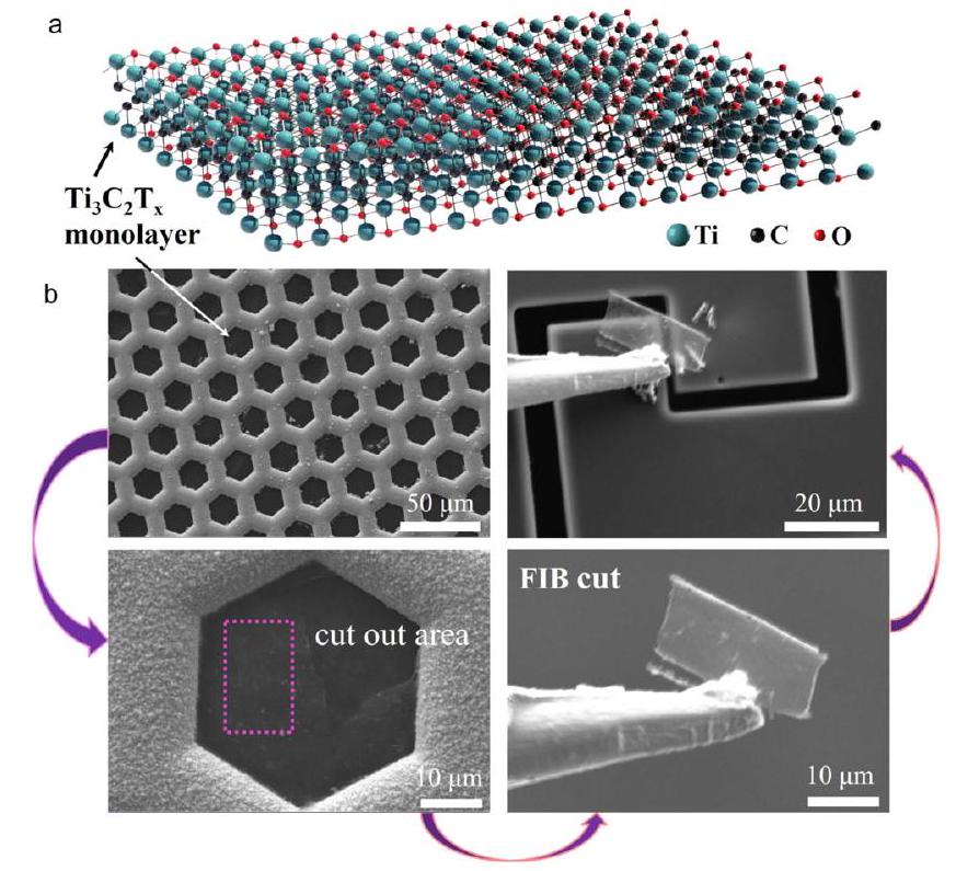
الشكل 1 | صور تخطيطية وصور مجهر إلكتروني لمسحوق أحادي الطبقة
عملية النقل.
هيكل لـ طبقة أحادية. ملاحظة: مجموعات السطح النهائية
يمكن أن تظهر عدة أجزاء أخرى، والتي يمكن أن تكون فلوريد (-F)، أكسيد (
)، هيدروكسيل ( -OH )، وهكذا، يتم عرض مجموعة سطحية واحدة فقط في هذه الصورة.
رسم توضيحي تخطيطي لـ
عملية نقل الطبقة الأحادية. يتم نقل العينة الموجودة على حافة شبكة النحاس إلى جهاز النانو الميكانيكي “الدفع والسحب” (PTP) عن طريق قطع FIB والمناورة.
هيكل لـ
النتائج
نقل الطبقة الأحادية
عينات
نقل طبقة أحادية ناجح
إضافة النانوورقة (الشكل 1أ) إلى جهاز PTP هي خطوة حاسمة للاختبار النانوميكانيكي في الموقع. لهذا الغرض، قمنا بتطوير نهج نقل جاف فريد (الشكل 1ب)، والذي تم تعديله من الطريقة السابقة.
. على وجه التحديد، الطبقة الأحادية المحضرة
تم إسقاط التعليق على شبكة نحاسية بفتحات 400 (بدون فيلم كربوني) وتم تجفيفها في فراغ (إجراء تخليق الطبقة الأحادية)
تم تفصيل التعليق في الشكل التوضيحي التكميلي 1). تم لصق طبقات النانو أحادية الطبقة على حواف شبكة النحاس، مما يسهل بشكل كبير عملية النقل اللاحقة (إذا تم تجفيف تعليق الطبقة الأحادية على حامل مسطح، سيكون من الصعب نقل طبقات النانو بسبب قوة فان der Waals). بعد ذلك، تم لصق جانب واحد من طبقة النانو بواسطة بلاتين تم ترسيبه بواسطة شعاع الإلكترون على المجس الميكانيكي، وتم قطع الجوانب الثلاثة الأخرى من طبقة النانو بواسطة شعاع الأيونات المركزة Ga (FIB) لنقل طبقة النانو. تم نقل طبقة النانو الناتجة إلى
منطقة التمدد في وسط جهاز PTP الميكروي.
الأغشية النانوية المعلقة على الجهاز النانوميكانيكي شبه شفافة تقريبًا بسبب طبيعتها أحادية الطبقة. المناور و
تم قطع النانو شيت وفصلها بواسطة FIB.
توصيف الطبقة الأحادية
عينات
كما هو موضح في صورة SEM (الشكل 2a)، كلا طرفي الطبقة الأحادية
تم تثبيت النانو شيت على جهاز PTP النانوميكانيكي بواسطة بلاتين تم ترسيبه بواسطة شعاع الإلكترون، وتم تعليق النانو شيت فوق الفجوة وتمت معالجته بواسطة FIB إلى الشكل والحجم المطلوبين لاختبار الشد. خلال الاختبار، تم استخدام مسبار exert exerting قوة دفع على المدخل نصف الكروي (المشار إليه بالسهم الأحمر). يقوم جهاز PTP الميكروي بتحويل قوة الدفع إلى قوة شد مسطحة على
من خلال آلية “الدفع إلى السحب” بمعدل تحميل
يمكن حساب قيمة الحمل من قيمة التحويل لـ

الشكل 2 | خطوات التجربة وتوصيفها
طبقة أحادية. جهاز النانو الميكانيكي “الدفع إلى السحب” (PTP) يحول الضغط على المدخل نصف الكروي إلى قوة شد على العينة تحت المجهر الإلكتروني الماسح.
تظهر الصورة المكبرة للمنطقة الحمراء في (أ)
طبقة أحادية من المنطقة الممدودة التي تم قطعها إلى مستطيل بواسطة FIB، الأسهم البرتقالية تمثل اتجاه الشد. ج صورة مقطع عرضي بتقنية STEM لـ
تمت ملاحظة طبقة أحادية على طول سطح الكسر للعينة المختبرة. طبقتان من ذرات الكربون (مشار إليهما بأسهم بنفسجية) متشابكتان مع ثلاث طبقات من ذرات التيتانيوم (مشار إليها بأسهم زرقاء) بالترتيب
يمثل Ti بالقرب من السطح و
لـ Ti المركزي)، والمجموعات الوظيفية مثل ذرات O و F (المعلمة بالأسهم الحمراء) موزعة على سطح
.
صورة TEM ونمط SAED بلوري لـ
طبقة أحادية.
محرك المشط الكهروستاتيكي في المجس المسطح، وتم تسجيل بيانات الحمل والإزاحة. الشكل
يظهر صورة SEM لطبقة أحادية
النانو شيت بعد الطحن باستخدام FIB. عرض وطول
هم
و
، على التوالي، واتجاه السهم البرتقالي المقابل هو اتجاه الشد للعينة.
سمك الطبقة الأحادية
سمك النانو شيت هو معلمة حاسمة للتحليل اللاحق للنتائج التجريبية. بشكل عام، فإن مصطلح سمك المواد ثنائية الأبعاد أحادية الطبقة غير محدد بشكل جيد. على سبيل المثال، تم قياس سمك الجرافين أحادي الطبقة باستخدام AFM بقيمة تتراوح من 0.4 إلى
. ومع ذلك، في الدراسة الفعلية لحساب الخصائص الميكانيكية، تم استخدام السماكة الاسمية لطبقة الجرافين الأحادية، والتي كانت
تم استخدام السماكة الاسمية أيضًا في دراسات أخرى لمعايرة سماكة المواد ثنائية الأبعاد.
على الرغم من أنه يمكن قياس سمكها وتقديره بواسطة AFM، إلا أن دقة هذه الطريقة تتأثر بعوامل مختلفة.
مثل خصائص السطح لـ
وتفاعل رأس المجهر النفقي مع سطح
وبالمثل، فإن سمك الطبقة الأحادية الذي تحدده حيود الأشعة السينية (XRD) يعتمد على الماء وجزيئات أخرى مدفونة أثناء القياس.
يمكن أن تفرط كلا الطريقتين في تقدير السماكة الاسمية للطبقة الأحادية.
، مما يؤدي إلى عدم اليقين في نتائج القياس. لذلك، في هذا العمل، فإن السماكة الاسمية للطبقة الأحادية
بمقدار 0.98 نانومتر تم استخدامه
كما هو موضح في الشكل 2c، مقطع حافة الكسر للمعلق
تمت دراسة النانوورقة بعد اختبار ميكانيكي باستخدام مجهر الإلكترون الناقل الماسح المصحح للانحراف (AC-STEM)، الذي تحقق من سمك الطبقة الأحادية.
.
خصائص
تم تأكيدها بواسطة حيود الأشعة السينية (XRD، الشكل التكميلي 2a)، مطيافية الأشعة السينية للأشعة الإلكترونية (XPS، الشكل التكميلي 2b-d، الشكل التكميلي 3)، مطيافية الأشعة السينية بتشتت الطاقة (EDX، الشكل التكميلي 4) ورسم الخرائط العنصرية (الشكل التكميلي 5). تم تعليق
تمت أيضًا دراسة النانوصفائح باستخدام مجهر الإلكترون الناقل (TEM). كما هو موضح في الشكل 2d، تؤكد أنماط حيود الإلكترون في المنطقة المختارة (SAED) المقابلة التي تحتوي على مجموعة واحدة فقط من أنماط الحيود السداسية الطبيعة البلورية وبنية الكربيد السداسية لـ
، مما يظهر الجودة العالية لـ
الأغشية النانوية. خلال عملية ترسيب البلاتين، سيتسرب البلاتين حتمًا إلى غرفة المجهر الإلكتروني الماسح. ومع ذلك، من المعروف جيدًا أن جزيئات البلاتين المتقطعة التي تم رشها تظهر خصائص فضفاضة وناعمة، بينما
تتمتع الأوراق النانوية بخصائص ميكانيكية قوية وهشة، مما لن يؤثر بشكل كبير على قياس الخصائص الميكانيكية. الطبيعة البلورية للعينة المختبرة
تم تأكيد ذلك من خلال سلسلة من أنماط SAED من الحافة إلى منطقة المركز في الشكل التكميلية 6a-c. على وجه التحديد، منطقة حافة الكسر للعينة المختبرة
تمت دراسة العينة على جهاز PTP بشكل أعمق بواسطة TEM، كما هو موضح في الشكل التوضيحي 6a، وأظهر نمط SAED أن هيكلها البلوري ظل كما هو. في منطقة الحافة من العينة المختبرة بعد قطعها بواسطة FIB، تم إظهار عدم التجانس المحلي (الشكل التوضيحي 6b) على الرغم من أنه تم ضبط الحد الأدنى من التيار وأكد SAED المقابل عدم تغيير الهيكل البلوري. بالنسبة للجزء المركزي من العينة المختبرة
MXene على PTP، الشكل التوضيحي الإضافي 6c لا يظهر أي تأثيرات من
تساقط وكمية صغيرة فقط من بقايا البلاتين غير المتصلة، ويشير تحليل SAED المقابل إلى جودة عالية. الشكل التوضيحي 6d يظهر صورة STEM بتكبير منخفض لمنطقة حافة الكسر للعينة المختبرة.
عينة على PTP، عرض مكبر لمنطقة المستطيل الأحمر يظهر السطح المقطعي المكسور. نظرًا لوجود الطبقات المتعددة
تُكسر النانوصفائح طبقة تلو الأخرى
، ولكن لم يتم ملاحظة أي هيكل متعدد الطبقات أو طبقات غير مكتملة من حواف الكسر في الشكل التوضيحي 6a والشكل التوضيحي 6c و6d، مما يشير إلى طبيعة العينة المختبرة كطبقة واحدة. علاوة على ذلك، تم قياس سمك عدد كبير من العينات بواسطة AFM. كما هو موضح في الشكل التوضيحي 7، تتجاوز نسبة الطبقات الأحادية
كما هو موضح في إحصائيات السماكة (الجدول التكميلي 1)، التي
يدعم بشكل أكبر وجود الطبقات الأحادية في المنتج الناتج.
اختبار الشد في الموقع لطبقة أحادية فردية
أوراق نانوية
لتحقيق الخصائص المرنة وقوة الشد للطبقة الأحادية
تجارب الشد في الموقع التي تتحكم فيها الإزاحة لطبقة واحدة
تمت في جهاز SEM لإصدار المجال. قبل اختبار الشد، تم ملاحظة المسبار نصف الكروي لجهاز PTP النانوميكانيكي بواسطة SEM في نفس المستوى مع المجس الميكانيكي. خلال عملية الشد، كانت كلا طرفي العينة ملتصقة بإحكام بجهاز PTP دائمًا، ولم يُلاحظ أي انزلاق في منطقة التداخل حتى حدوث الكسر. تم مراقبة وتسجيل التجربة بالكامل في الوقت الحقيقي (كما هو موضح في الفيلم التكميلي 1، الفيلم التكميلي 2). لحساب قوة الكسر للطبقة الأحادية
يجب قياس أقصى استطالة للعينة أثناء عملية الشد.
كما هو موضح في الشكل 3a و b، من خلال لقطات SEM قبل وبعد اختبار الشد، فإن الحد الأقصى للإجهاد الهندسي للطبقة الأحادية
يمكن أن تصل الشريحة النانوية قبل الكسر إلى
تظهر الشكل 3 ج العينة التي فشلت تمامًا مع كسر هش نموذجي. يظهر الشكل 3 د منحنى الحمل-الإزاحة المقابل. من الجدير بالذكر أن ميل المنحنى كان صغيرًا في المرحلة الأولية، بسبب لمس المجس الميكانيكي فقط للموشر نصف الكروي، ولم تكن العينة مشدودة عندما كان يتم تشغيل زنبرك الجهاز النانوميكانيكي فقط. لذلك، فإن ميل المرحلة الأولية يتوافق مع الصلابة الجوهرية للجهاز النانوميكانيكي. كانت المرحلة الثانية هي عملية انتقال العينة من حالة الاسترخاء إلى حالة الشد. في بداية السهم البرتقالي، كانت الطبقة الأحادية
تم تمديد النانو شيت. يمثل ميل المنحنى في المرحلة الثالثة الصلابة الكلية للعينة والجهاز النانوميكانيكي. بدءًا من النجمة الأرجوانية، تم سحب العينة وانخفض الحمل المطبق بشكل حاد، واستمر المجس في التحميل حتى توقف. ميل المرحلة النهائية هو نفسه ميل المرحلة الأولى، وكلاهما يمثل الصلابة الجوهرية للجهاز النانوميكانيكي. هنا، الصلابة الفعلية للشد للطبقة الأحادية.
الورقة النانوية تساوي إجمالي صلابة المرحلة الثالثة ناقص الصلابة الكامنة للجهاز النانوميكانيكي، والصلابة الشد الفعلية للطبقة الأحادية.
يمكن حساب النانو شيت على أنه
الطول والعرض الفعليان لمنطقة العينة المقاسة هما
و
ومعامل المرونة ثنائي الأبعاد
يتم حسابه. بموجب فرضية الاستمرارية
تم إنشاء نموذج طريقة العناصر المحدودة (FEM) استنادًا إلى النتائج التجريبية لتحديد الإجهاد والانفعال أحادي المحور للعينة، ولدراسة توزيع ونمط تطور مجالات التشوه والإجهاد أثناء التحميل (الشكل التكميلي 12). تظهر النتائج أن فرضية الإجهاد أكثر منطقية من فرضية الانفعال لمعظم مناطق العينة. لذلك، تحت فرضية الإجهاد أحادي المحور، فإن معامل يونغ ثلاثي الأبعاد
يتم حسابه باستخدام
ورقة نانوية بسماكة طبقة أحادية تبلغ 0.98 نانومتر.
العديد من الطبقات الأحادية
تم استخدام الأوراق النانوية في عملنا. للأسف، بسبب الصعوبة الكامنة في عمليات الاختبار النانوميكانيكية وهشاشة الطبقة الأحادية.
، فشل معظمها في النقل. تم إجراء خمسة اختبارات ناجحة في المجموع. توضح الجدول 1 الأبعاد، معامل يونغ، وقوة الشد للعينات المختبرة. متوسط معامل يونغ وقوة الكسر هو
و
، على التوالي.
نقاش
معامل يونغ الفعال
المقاسة في التجارب المذكورة أعلاه قريبة من القيمة المتوقعة نظريًا البالغة 502 جيجا باسكال بواسطة محاكاة الديناميكا الجزيئية (MD).
جدير بالذكر أن معامل يونغ للطبقة الأحادية
الأغشية النانوية التي تم قياسها باستخدام جهاز PTP النانوميكانيكي تتجاوز بكثير القيمة المبلغ عنها سابقًا

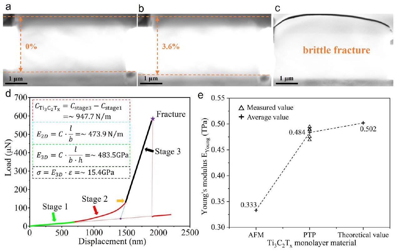
الشكل 3 | كسر الشد للطبقة الأحادية
صور نانوية ومقارنة الخصائص. تظهر صورة SEM أن
تم شد العينة بالكامل عند
ضغط.
صورة SEM للعينة قبل كسر الشد تظهر ذروة إجهاد قدرها
. تمثل الخطوط المنقطة البرتقالية الحافتين لعينة الاختبار. ج شكل الكسر الهش للعينة بعد الفشل، والنتائج المرتبطة مدرجة في الجدول 1 (العينة رقم 4). د منحنى الحمل-الإزاحة المقاس. الـ
تظهر صيغة الإدخال عملية حساب الخصائص الميكانيكية (انظر القسم 5.2 لمزيد من التفاصيل). مقاومة الشد
ويمكن حساب معامل يونغ ثلاثي الأبعاد، حيث
و
هي صلابة الشد، الطول في المنطقة الممدودة، العرض، السماكة، والانفعال للعينة، على التوالي.
مقارنة معامل يونغ طبقة أحادية من اختبار انغماس AFM، “الدفع إلى السحب” (PTP) القيم الشد في الموقع والقيم النظرية.
( ) بطريقة النانو إندينتيشن (الشكل 3e)
، مما يتيح إعادة تحديد الخصائص الميكانيكية للطبقة الأحادية
الأغشية النانوية. بالمقارنة مع الخصائص الميكانيكية لمواد ثنائية الأبعاد أحادية الطبقة الأخرى التي تم قياسها من خلال تجارب الشد في الموقع المشابهة لآليات PTP (الشكل التكميلي 8)، فإن معامل يونغ الفعال لـ
MXene أعلى من القيمة المتوسطة لـ
لكنها أقل من تلك الخاصة بالجرافين
. لذلك، كمرشحين واعدين للأجهزة الميكرو/نانو-إلكترو ميكانيكية التي تتطلب خصائص ميكانيكية عالية، بالإضافة إلى استخدامها كمواد تعزيز في المركبات،
يمثل MXene بديلاً مناسبًا للجرافين في مجال المواد ثنائية الأبعاد. ومن الجدير بالذكر أن كل من الجرافين و
يتم تصنيعها بواسطة تقنيات ترسيب البخار الكيميائي (CVD). فقط
ويجب أن يتم حفر وإزالة الركائز من PMMA، مما يجعل من الممكن تثبيت العينات بسهولة مع جهاز الاختبار مباشرة وجعل عملية القياس بسيطة. التيتانيوم
تمت معالجة نانوصفائح MXene المختبرة في هذا العمل بالتآكل والتصنيف في المحلول بسبب إجراء التصنيع الفريد، مما يزيد بشكل كبير من صعوبة الاختبار الميكانيكي في الموقع للعينات المعالجة بالمحلول. علاوة على ذلك،
MXene هو واحد فقط من العديد من المواد ثنائية الأبعاد التي تم تصنيعها باستخدام تقنيات قائمة على المحاليل، والخطوة الصعبة في نقل العينة تعتبر تعليمية للتحقيق المستقبلي في الخصائص الميكانيكية للمواد ثنائية الأبعاد المعالجة بالمحلول. إنه
مقارنة معامل يونغ
(
الجدول 1 | الخصائص الميكانيكية للطبقة الأحادية
أوراق نانوية
عينة # | الطول (
|
عرض (
|
معامل يونغ
|
الانفعال الشد الأقصى (%) | مقاومة الشد (جيجا باسكال) |
1 | 2.5 | ٥ | ٤٨٨.٢ |
|
|
2 | ٢.٥ | ٥ | ٤٦٩.٢ |
|
|
٣ | ٢.٥ | ٥ | ٤٧٥.٦ |
|
|
٤ | ٢.٥ | ٥ | 494.6 |
|
|
٥ | 2.5 | ٥ | ٤٨٩.٨ |
|
|
متوسط |
|
|
|
من الجدير بالذكر أن معامل يونغ الفعال للطبقة الأحادية
طبقات النانو أعلى بثلاثة أوامر من حيث الحجم مقارنةً بالطبقات المتعددة المبلغ عنها سابقًا
. هذه النتيجة تدعم أهمية قياسات الطبقة الأحادية من أجل الكشف عن الخصائص الفيزيائية الجوهرية لـ MXene ومركباته.
يمتلك MXene إجهادًا مرنًا هندسيًا فعالًا قدره
ويظهر كسرًا هشًا، مما سيوفر إمكانيات هائلة لتطبيقات MXene في هندسة الإجهاد. بالتفصيل، يؤدي الإجهاد الشد إلى زيادة أكبر
أطوال الروابط، والضغط الداخلي سيجعل مركز نطاق d لذرات التيتانيوم أقرب إلى مستوى طاقة فيرمي، مما يعطي
الأغشية النانوية تحتوي على مواقع نشطة وفيرة، مما سيعزز من امتصاص المتفاعلات/الوسطاء لتسريع التأثير الحفزي
الانفعال المرن لـ
يكفي لإعطاء
المواد ذات خصائص اقتران ميكانيكي كهربائي كيميائي ممتازة، والتي يمكن توليدها ميكانيكياً وكيميائياً لتغيير بنية المادة لضبط هياكلها الإلكترونية وخصائصها الكيميائية، مما يسمح أيضاً بالعديد من التطبيقات في مجال تخزين الطاقة.
يمكن أن يؤدي تطبيق الضغط ومجال كهربائي أيضًا إلى
خصائص MXene الواعدة للأجهزة النانوية البصرية مع فجوة نطاق قابلة للتعديل بواسطة المجال الكهربائي
. بالإضافة إلى ذلك، الخصائص المرنة لـ
تجعل MXene مناسبة للتطبيقات في الجلد الروبوتي المرن
أفلام مركبة هيكلية
طلاءات واقية
، وحقول الاستشعار
.
قوة الكسر الشد الفعالة لـ
(الجدول 1) أقل من القيمة النظرية لـ
(الجدول التكميلي 2). لفهم أصل هذا الاختلاف، تم دراسة شكل الطبقة الأحادية
تمت ملاحظة النانو شيت بعناية في الموقع بواسطة SEM/STEM، والتي لم تظهر أي عيوب أو تشققات مرئية. لذلك نعتقد أن الانخفاض في قوة الشد ناتج عن عيوب الحواف التي هي أصغر من حد التوصيف، والتي تشكلت أثناء عملية القطع والتشكيل باستخدام FIB، مما أدى إلى تقليل قوة الكسر للطبقة الأحادية.
للتحقق من هذه النقطة، قمنا بمحاكاة تأثير العيوب الحادة على قوة الكسر من خلال محاكاة الديناميكا الجزيئية. استنادًا إلى دراسات حديثة حول العيوب الهيكلية الناتجة عن حقن الإشعاع الأيوني في MXenes ثنائية الأبعاد.
تم تحديد ثلاثة أنواع مختلفة من عيوب الحواف وتم إثبات اعتماد عرض العينة على المقياس (الشكل 4أ). الهيكل الذري لـ
مرتبة بشكل سداسي مع خصائص متأصلة
توجهات المواد لشكل الكرسي والموجة المتعرجة قوة الكسر للطبقة الأحادية
تم محاكاة نانوصفائح بثلاثة مقاييس عرض مختلفة على طول الاتجاهين مع تثبيت كلا الطرفين على التوالي. النتائج الثمانية عشر لقوة الكسر المقابلة موضحة في الشكل 4b. الإحداثي العمودي هو نسبة القوة المثالية (
) من الطبقة الأحادية الخالية من العيوب
الأغشية النانوية إلى قوة الكسر (
) مع عيوب حافة مزروعة. تُظهر المنطقة المظللة باللون الأخضر نطاق القيم التجريبية المقاسة بواسطة طريقة PTP. من النتائج المحاكاة، يمكن ملاحظة أن العيوب الحافة الناتجة أثناء قطع FIB يمكن أن تقلل بالفعل من قوتها على الكسر. القيم التجريبية لـ
تتراوح بين 1.033 و 1.347. القيم المحاكية لـ 18 نوعًا من مقاييس العرض المختلفة وعيوب الحواف قريبة من نطاق القيم المقاسة تجريبيًا. يتناقص تأثير عيوب الحواف على مقاومة الشد للعينة مع زيادة عرض العينة، وتتناسب القيم المحاكية بشكل أفضل مع القيم التجريبية، مما يشير إلى إمكانية قياس تأثير عيوب الحواف. من خلال استخدام تيار قطع أصغر في FIB، يمكن تقليل تركيز العيوب عند حافة العينة بشكل فعال.
توجهات المواد لشكل الكرسي والموجة المتعرجة

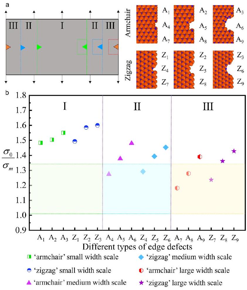
الشكل 4 | محاكاة الديناميكا الجزيئية لقوة الكسر لمقاييس عرض مختلفة
طبقات أحادية مع عيوب حافة محتملة ناتجة عن FIB. محاكاة MD لـ
(الشكل التوضيحي 9)، مما يحسن القوة الفعلية للكسر لـ
. نظرًا لحدوث انتشار البلاتين والتبخير الموضعي لـ
خلال الإجراء التجريبي، من الضروري تقديم تحليل شامل وتوضيح لتأثيرات البلاتين و
على نتائج الاختبار الميكانيكي للعينات. كما ذُكر سابقًا، تم ترسيب البلاتين على سطح طبقة أحادية
تتميز الأوراق النانوية أثناء الاختبار بطبيعتها اللينة ولن تؤثر على الخصائص الميكانيكية للمواد القوية والصلبة.
MXene. يتم التحقق من النتائج أيضًا من خلال طرق تجريبية. في البداية، يتم استخدام ترسيب البلاتين عالي الطاقة لتثبيت كلا الطرفين من
، مما أدى إلى أن يصبح العينة غير شفافة تحت المجهر الإلكتروني الماسح (الشكل التكميلي 10) بسبب ترسيب البلاتين على سطح العينة، والخصائص الميكانيكية المقاسة موضحة في الجدول 1 (العينة #1-3). بعد ذلك، من خلال ضبط ترسيب البلاتين على طاقة منخفضة، تحافظ العينة على طبيعتها الشفافة، والخصائص الميكانيكية المقاسة معروضة في الجدول 1 (العينة #4-5). بالإضافة إلى ذلك، تشير نمط SAED في الشكل التكميلي 6a والشكل التكميلي 6c إلى أن خصائص العينة المختبرة
تظل MXene دون تغيير، وتؤكد مقارنة النتائج التجريبية أن ترسيب البلاتين لم يؤثر بشكل كبير على الاختبار. خلال عملية قطع FIB، قمنا بتعيين حد أدنى من التيار قدره 1 pA لتقليل تركيز عيوب الحواف. كما يتضح من الشكل التوضيحي 6a-c، تأثير
كان التركيز على العينات محدودًا على الحواف المقطوعة، والطبيعة البلورية لـ
ظل الـ MXene دون تغيير. من الجدير بالذكر أنه إذا كان هناك عدد كبير من العيوب في المنطقة الداخلية للمواد ثنائية الأبعاد، فإن ذلك سيؤثر بشكل واضح على سلوك الكسر ويؤدي إلى مراحل متعددة من التشققات.
علاوة على ذلك، تظل قوة الكسر للعينة ذات العيوب الحافة في نفس نطاق القوة المثالية للعينة الخالية من العيوب، وتتجاوز القياسات التجريبية نصف القيمة المثالية (أي، القوة الفائقة العميقة).
). هذه تظهر بفعالية أن تأثير FIB على قوة الكسر للطبقة الأحادية
تقتصر الأوراق النانوية على منطقة الحافة فقط. بالإضافة إلى ذلك، تم إثبات هذه الظاهرة أيضًا في دراسات أخرى باستخدام FIB لمعالجة المواد ثنائية الأبعاد.
استنادًا إلى نتائج المحاكاة المذكورة أعلاه، فإن تأثير عيوب الحواف على العينات المختبرة يعتمد على مقياس العرض. في هذا العمل، تم تثبيت عرض العينات المختبرة عمدًا عند
(زيادة الامتداد ليشمل العرض الكامل للفجوة الشد)، مما قلل من تأثير عيوب الحواف على قوة الشد. ومن الجدير بالذكر أن هذا العيب الذري في الحافة ليس شقًا وله تأثير ضئيل على معامل المرونة للعينة، مما يفسر نتائج اختبارات الشد في الموقع لدينا للطبقة الأحادية الفردية.
أوراق نانوية
باختصار، نجحنا في تنفيذ اختبارات الشد الميكانيكي في الموقع لطبقة أحادية فردية.
الأغشية النانوية باستخدام جهاز PTP النانوميكانيكي في SEM. بالمقارنة مع اختبار التوطين العرضي لاختبار النانو-indent في AFM، يمكن لجهاز PTP تحقيق تمدد موحد للعينة في المستوى، وخصائصها الميكانيكية للطبقة الأحادية.
يمكن قياسه بدقة. معامل يونغ للطبقة الأحادية
قريب من القيمة المتوقعة نظريًا البالغة 502 جيجا باسكال. الطبقة الأحادية
أظهرت الأوراق النانوية كسرًا هشًا بمتوسط إجهاد مرن قدره
، مما يوفر فرصة لتطبيق
في هندسة الإجهاد المرن. علاوة على ذلك، فإن الفرق بين القوة الفعلية للكسر التي تم قياسها تجريبيًا
والقيمة المثالية لـ
يُنسب ذلك إلى عيوب الذرات على حافة العينة، وتتناقص هذه الفجوة مع زيادة عرض العينة. يتم قياس تأثير العيوب الحادة على قوة الكسر من خلال محاكاة الديناميكا الجزيئية، ويمكن تحسين قوة الكسر الهندسية من خلال تعديل حالة الحافة للطبقة الأحادية.
أوراق نانوية.
طرق
تحضير العينات لاختبارات الشد
الطبقة الأحادية كبيرة الحجم
تم تصنيع النانوصفائح (الشكل التكميلي 1) باستخدام تقنية تحسين فصل الطبقات ذات الكثافة المنخفضة (MILD). على وجه التحديد، اخترنا شبكة 200.
) من MAX
مرحلة ، باستخدام
طريقة النقش: 1.6 جرام من LiF ذاب ببطء في 40 مل من
، مع التحريك لمدة 15 دقيقة لجعله يذوب تمامًا، و1 جرام من
تم إضافته ببطء. النقش في
لمدة 30 ساعة. تم غسل المحلول المنقوش مرتين أولاً بـ
لإزالة الفائض من LiF، ثم تم غسله وطرده مركزيًا باستخدام الماء المقطر بسرعة طرد مركزي
لمدة 5 دقائق في كل مرة، حوالي
مرات، لجعل pH الحل أكبر من 6. تم جمع الراسب بعد الترشيح تحت الفراغ وأخيرًا وضعه في فرن تجفيف تحت الفراغ وتجفيفه عند
لمدة 12 ساعة. الطبقة الأحادية ذات الحجم الكبير والجودة العالية
تم الحصول على التعليق بواسطة طريقة الطبقات من خلال الاهتزاز اليدوي لمدة 30 دقيقة والطرد المركزي عند
لمدة 30 دقيقة.
مرحلة
نموذج نقل لاختبارات الشد
طبقة أحادية
تم نقل النانو شيت إلى جهاز PTP النانوميكانيكي باستخدام تقنية النقل الجاف لاختبار الشد في الموقع. كان فقدان حجم العينة ناتجًا عن خطوات ترسيب البلاتين وقطع FIB خلال عملية النقل. اخترنا شبكة نحاسية بفتحات 400 (بدون فيلم كربوني) ولصقناها مباشرة على طاولة عينة SEM لجهاز SEM ذو الانبعاث الميداني باستخدام لاصق موصل، ثم قمنا بإسقاط تعليق أحادي الطبقة على الشبكة النحاسية. بعد التجفيف في الفراغ، تمت إزالة النانو شيت بواسطةManipulator. ومع ذلك، قد ينحني النانو شيت الذي تمت إزالته بسبب FIB وManipulator، لذا تم ترسيب حلقة من البلاتين حول حافة منطقة العينة المختارة لتعزيزها قبل النقل. تم محاذاة النانو شيت الذي تمت إزالته مع منطقة الشد لجهاز PTP، ولا يمكن كسر العينة في لحظة النقل إلى جهاز PTP. في عملية فصلManipulator عن
يجب أيضًا استخدام FIB لقص النانو شيت بالكامل لمنع أخذ العينة من موضعها الأصلي. أثناء نقل النانو شيت إلى منطقة الشد في PTP، يجب تدوير منصة عينة SEM ذات الانبعاث الميداني.
، وجهاز PTP عمودي على كاميرا FIB بحيث لا يحدث انحراف في القطع أثناء عملية القطع. أخيرًا، تم قطع طبقة النانو الأحادية إلى أشكال بعرض
وطول 2.5
استخدام FIB لاختبار الشد. من أجل تقليل ضرر الإشعاع أثناء قطع FIB، تم ضبط جهد تسريع منخفض جداً يبلغ 2 كيلو فولت وتيار مسبار صغير يبلغ 1 بيكو أمبير.
اختبار الشد باستخدام المجهر الإلكتروني الماسح في الموقع
طبقة أحادية
تم اختبار الأوراق النانوية في تجارب الشد أحادية المحور في غرفة مجهر الإلكترون Carl Zeiss CossBeam340، حيث تم تسجيل فيديو الشد في الموقع عند جهد منخفض قدره 5 كيلو فولت لتقليل تأثيرات شعاع الإلكترون. قبل التجارب، تم محاذاة جهاز Brukers-Hysitron PI88 picindenter (الشكل التكميلي 11a) مع المثقاب نصف الدائري لجهاز PTP (الشكل التكميلي 11b)، وتم معايرة معلمات محرك المشط الكهروستاتيكي في المجس المسطح بواسطة الهواء. تحت التحكم في الإزاحة من
تم تحميل جهاز PTP باستخدام مسبار PI88، وسجل مستشعر الضغط منحنى التحميل-الإزاحة. يقوم جهاز PTP بتحويل الضغط على المسبار إلى تمدد أحادي المحور للعينة. يتم قياس إجهاد الشد للعينة مباشرة من الفيديو الخاص بالشد في الموقع باستخدام SEM، ويتم حساب الإجهاد من الحمل مقسومًا على المساحة المقطعية. من خلال تحليل منحنيات الحمل-الإزاحة، يتم تحديد معامل يونغ وقوة الشد للطبقة الأحادية.
يمكن حساب النانوشرائح. على وجه التحديد، فإن صلابة النانوورقة أحادية الطبقة تساوي صلابة المرحلة الثالثة من منحنى الحمل-الإزاحة ناقص صلابة زنبرك الجهاز النانوميكانيكي في المرحلة الأولى. يتم حساب معامل يونغ ثنائي الأبعاد وثلاثي الأبعاد كما يلي:
في المعادلة،
، و
تمثل صلابة الشد، الطول، العرض، والسماكة للعينة في منطقة الشد على التوالي. هنا، كان طول وعرض العينة
و
“، على التوالي. بشكل عام، فإن مصطلح السماكة غير محدد بشكل جيد للمواد ثنائية الأبعاد، تستخدم هذه الدراسة سماكة “اسمية” للطبقة الأحادية
MXene، باتباع نهج مشابه لذلك المستخدم في الجرافين. سمك الطبقة الأحادية
تم تحديد سمك النانوورقات على أنه 0.98 نانومتر بواسطة
STEM وDFT. من الجدير بالذكر أنه يجب افتراض حالات الإجهاد والانفعال لأن العينة هي طبقة أحادية من نانو شيت بسماكة على مستوى النانومتر. في اختبار الشد الفعلي، لم يحدث انكماش في العنق على كلا الجانبين العرضيين للعينة المعلقة. بالاقتران مع نتائج محاكاة تحليل العناصر المحدودة (الشكل التكميلي 12). تظهر النتائج أنه إذا أخذنا أي مستوى على طول اتجاه السماكة، فإن حالة الإجهاد للطبقة الأحادية
هو نفسه، ويمكن تجاهل القوة في اتجاه سمك العينة. بالإضافة إلى ذلك، فإن مقاومة الشد النهائية لـ
يمكن حسابه من خلال اعتبار أقصى إجهاد شد
كصيغة لمقاومة الشد
.
محاكاة الديناميكا الجزيئية (MD)
نظرًا لأنه من شبه المستحيل ملاحظة تأثير العيوب الحافة على الخصائص الميكانيكية للعينات على المستوى الذري، فإن الخصائص الميكانيكية للطبقة الأحادية
تمت دراسة النانوصفائح ذات العيوب الذرية في الحواف من خلال محاكاة الديناميكا الجزيئية. تم إجراء جميع المحاكاة في المحاكي الضخم للذرات/الجزيئات (LAMMPS). تم نمذجة الشد الأحادي للطبقة الأحادية.
تمت مع عينة بطول
وعرض
،
، على التوالي. كانت شروط الحدود دورية، على طول اتجاهات الأريكة والزقزوق، على التوالي. تم وضع جميع العيوب الذرية الثلاثة عند حافة العينة. تم تطبيق إجهاد شد أحادي المحور موحد بمعدل تحميل قدره
قبل أن تتحرك الذرات وفقًا لمعادلتها الحركية. لأن العينات المستخدمة في التجربة هي بلورات مفردة عالية الجودة.
تم إثبات عقلانية إزاحة الذرات من خلال افتراض تشوه متجانس لشبكة البلورة. إن ارتفاع درجة الحرارة أثناء التحميل لا يتجاوز 10 كلفن. لذلك، فإن تأثير التذبذب الحراري على نتائج المحاكاة يقع ضمن نطاق معقول، وعملية التشوه الشد والانكسار للعينة لا تتأثر. يتم استخدام دالة الطاقة المحتملة من الجيل الثالث COMB3 لوصف التفاعلات بين
الذرات، تم تحسين COMB3 للاستخدام مع الميزات التي تحاكي بشكل أكثر واقعية التفاعلات بين الذرات المختلفة لتوفير مرونة أكبر. القيم النظرية لمحاكاة قوة الكسر (
) للطبقة الأحادية
تظهر جداول الملحق 3 رقائق MXene النانوية المزروعة بثلاثة عيوب حافة بعرض مختلف.
توفر البيانات
جميع البيانات التي تم توليدها أو تحليلها خلال هذه الدراسة مدرجة في المقالة المنشورة وملفات المعلومات التكميلية الخاصة بها.
References
- Zheng, C. et al. Functional MXene-based materials for nextgeneration rechargeable batteries. Adv. Mater. 34, 2204988 (2022).
- Zou, J. et al. Additive-mediated intercalation and surface modification of MXenes. Chem. Soc. Rev. 51, 2972-2990 (2022).
- Cao, Z. et al. Low-tortuous MXene (TiNbC) accordion arrays enabled fast ion diffusion and charge transfer in dendrite-free lithium metal anodes. Adv. Energy Mater. 12, 2201189 (2022).
- Cao, J. M. et al. Two-dimensional MXene with multidimensional carbonaceous matrix: A platform for general-purpose functional materials. Prog. Mater. Sci. 135, 101105 (2023).
- Naguib, M. et al. Two-dimensional nanocrystals produced by exfoliation of
. Adv. Mater. 23, 4248-4253 (2011). - Lee, S. et al. Polymer-laminated
MXene electrodes for transparent and flexible field-driven electronics. ACS Nano 15, 8940-8952 (2021). - Feng, X. et al. Functional integrated electromagnetic interference shielding in flexible micro-supercapacitors by cation-intercalation typed
MXene. Nano Energy 72, 104741 (2020). - Gu, J. et al. Extremely robust and multifunctional nanocomposite fibers for strain-unperturbed textile electronics. Adv. Mater. 35, 2209527 (2023).
- Ahmed, B., Ghazaly, A. E. L. & Rosen, J. i-MXenes for energy storage and catalysis. Adv. Funct. Mater. 30, 2000894 (2020).
- Zheng, X. et al. MXene functionalized, highly breathable and sensitive pressure sensors with multi-layered porous structure. Adv. Funct. Mater. 33, 2214880 (2023).
- Ma, Z. et al. Ultraflexible and mechanically strong double-layered aramid nanofiber-
MXene/Silver nanowire nanocomposite papers for high-performance electromagnetic interference shielding. ACS Nano 14, 8368-8382 (2020). - Grützmacher, P. G. et al. Superior wear-resistance of
multilayer coatings. ACS Nano 15, 8216-8224 (2021). - Tan, D. et al. Monolayer MXene Nanoelectromechanical Piezoresonators with 0.2 zeptogram mass resolution. Adv. Sci. 9, 2201443 (2022).
- Bae, J. et al. Towards Watt-scale hydroelectric energy harvesting by
-based transpiration-driven electrokinetic power generators. Energy Environ. Sci. 15, 123-135 (2022). - Averbeck, S. R. et al. Stability of
MXene films and devices under clinical sterilization processes. ACS Nano 17, 9442-9454 (2023). - Peng, J. et al. A mechanically robust all-solid-state supercapacitor based on a highly conductive double-network hydrogel electrolyte and
MXene electrode with anti-freezing property. J. Mater. Chem. A 9, 25073-25085 (2021). - Jo, E. et al. Integration of a carbon nanotube network on a microelectromechanical switch for ultralong contact lifetime. ACS Appl. Mater. Interfaces 11, 18617-18625 (2019).
- Firestein, K. L. et al. Young’s modulus and tensile strength of
MXene nanosheets as revealed by in situ TEM probing, AFM nanomechanical mapping, and theoretical calculations. Nano Lett. 20, 5900-5908 (2020). - Wan, S. et al. Strong sequentially bridged MXene sheets. Proc. Natl. Acad. Sci. 117, 27154-27161 (2020).
- Borysiuk, V. N., Mochalin, V. N. & Gogotsi, Y. Molecular dynamic study of the mechanical properties of two-dimensional titanium carbides
(MXenes). Nanotechnology 26, 265705 (2015). - Gao, Y. et al. Elastic coupling between layers in two-dimensional materials. Nat. Mater. 14, 714-720 (2015).
- Castellanos-Gomez, A. et al. Elastic properties of freely suspended
nanosheets. Adv. Mater. 24, 772-775 (2012). - Lipatov, A. et al. Elastic properties of
monolayers and bilayers. Sci. Adv. 4, eaat0491 (2018). - Papageorgiou, D. G., Kinloch, I. A. & Young, R. J. Mechanical properties of graphene and graphene-based nanocomposites. Prog. Mater. Sci. 90, 75-127 (2017).
- Li, X., Sun, M., Shan, C., Chen, Q. & Wei, X. Mechanical properties of 2D materials studied by in situ microscopy techniques. Adv. Mater. Interfaces 5, 1701246 (2018).
- Lee, C., Wei, X., Kysar, J. W. & Hone, J. Measurement of the elastic properties and intrinsic strength of monolayer graphene. Science 321, 385-388 (2008).
- Falin, A. et al. Mechanical properties of atomically thin boron nitride and the role of interlayer interactions. Nat. Commun. 8, 15815 (2017).
- Cao, K. et al. Elastic straining of free-standing monolayer graphene. Nat. Commun. 11, 284 (2020).
- Shearer, C. J., Slattery, A. D., Stapleton, A. J., Shapter, J. G. & Gibson, C. T. Accurate thickness measurement of graphene. Nanotechnology 27, 125704 (2016).
- Bertolazzi, S., Brivio, J. & Kis, A. Stretching and breaking of ultrathin
. ACS Nano 5, 9703-9709 (2011). - Zhang, P. et al. Fracture toughness of graphene. Nat. Commun. 5, 3782 (2014).
- Lipatov, A. et al. Electrical and elastic properties of individual singlelayer
MXene flakes. Adv. Electron. Mater. 6, 1901382 (2020). - Ghidiu, M., Lukatskaya, M. R., Zhao, M. Q., Gogotsi, Y. & Barsoum, M. W. Conductive two-dimensional titanium carbide ‘clay’ with high volumetric capacitance. Nature 516, 78-81 (2015).
- Halim, J. et al. Transparent conductive two-dimensional titanium carbide epitaxial thin films. Chem. Mater. 26, 2374-2381 (2014).
- Wang, X. et al. Atomic-scale recognition of surface structure and intercalation mechanism of
. J. Am. Chem. Soc. 137, 2715-2721 (2015). - Li, Y. et al. in situ tensile testing of nanometer-thick two-dimensional transition-metal carbide films: Implications for MXenes acting as nanoscale reinforcement agents. ACS Appl. Nano Mater. 4, 5058-5067 (2021).
- Pelliciari, M. & Tarantino, A. M. Equilibrium and stability of anisotropic hyperelastic graphene membranes. J. Elast. 144, 169-195 (2021).
- Wei, C. & Wu, C. Nonlinear fracture of two-dimensional transition metal carbides (MXenes). Eng. Fract. Mech. 230, 106978 (2020).
- Yang, Y. et al. Brittle Fracture of 2D MoSe
. Adv. Mater. 29, 1604201 (2017). - Wang, X. et al. Strain engineering of a MXene/CNT hierarchical porous hollow microsphere electrocatalyst for a high-efficiency lithium polysulfide conversion process. Angew. Chem. Int. Ed. 60, 2371-2378 (2021).
- Wu, Y. et al. Anchoring sub-nanometer Pt clusters on crumpled paper-like MXene enables high hydrogen evolution mass activity. Adv. Funct. Mater. 32, 2110910 (2022).
- Wang, J. et al. Mechanochemistry-induced biaxial compressive strain engineering in MXenes for boosting lithium storage kinetics. Nano Energy 87, 106053 (2021).
- Zhang, X. et al. 3D crumbled MXene for high-performance supercapacitors. Chin. Chem. Lett. 31, 2305-2308 (2020).
- Chang, T. H. et al. Controlled crumpling of two-dimensional titanium carbide (MXene) for highly stretchable, bendable, efficient supercapacitors. ACS Nano 12, 8048-8059 (2018).
- Pham, K. et al. Strain engineering and electric field tunable electronic properties of
MXene monolayer. Mater. Res. Express 6, 065910 (2019). - Shao, Y. et al. Room-temperature high-precision printing of flexible wireless electronics based on MXene inks. Nat. Commun. 13, 3223 (2022).
- Li, K. et al. Thermal camouflaging MXene robotic skin with bioinspired stimulus sensation and wireless communication. Adv. Funct. Mater. 32, 2110534 (2022).
- Wan, S. et al. High-strength scalable MXene films through bridginginduced densification. Science 374, 96-99 (2021).
- Li, Y. et al. Cu-Modified
MXene with zincophilic and hydrophobic characteristics as a protective coating for highly stable Zn anode. Adv. Funct. Mater. 33, 2213416 (2023). - Yang, Z. et al. Self-assembly 3D porous crumpled MXene spheres as efficient gas and pressure sensing material for transient All-MXene sensors. Nano-Micro Lett. 14, 56 (2022).
- Pazniak, H. et al. Ion implantation as an approach for structural modifications and functionalization of
MXenes. ACS Nano 15, 4245-4255 (2021). - Sang, X. et al. Atomic defects in monolayer titanium carbide (
) MXene. ACS Nano 10, 9193-9200 (2016). -
. et al. Ion irradiation effects on two-dimensional for applications in extreme conditions: Combined Ab Initio and Monte Carlo simulations. ACS Appl. Nano Mater. 6, 3463-3471 (2023). - Hatam-Lee, S. M., Esfandiar, A. & Rajabpour, A. Mechanical behaviors of titanium nitride and carbide MXenes: A molecular dynamics study. Appl. Surf. Sci. 566, 150633 (2021).
- Dewapriya, M. A. N. & Meguid, S. A. Tailoring fracture strength of graphene. Comput. Mater. Sci. 141, 114-121 (2018).
- Li, S. et al. ‘Deep Ultra-Strength’-induced band structure evolution in silicon nanowires. J. Phys. Chem. C. 122, 15780-15785 (2018).
- Han, Y. et al. Large elastic deformation and defect tolerance of hexagonal boron nitride monolayers. Cell Rep. Phys. Sci. 1, 100172 (2020).
شكر وتقدير
ب.ز. يقر بمؤسسة العلوم الطبيعية الوطنية في الصين (رقم المنحة 52105145، رقم 12274124)، وبرنامج شنغهاي التجريبي للبحث الأساسي (رقم المنحة 22TQ1400100-6)، وصناديق البحث الأساسية للجامعات المركزية. ف.-ز.إكس. يشكر مشروع مجموعة البحث المبتكر لمؤسسة العلوم الطبيعية الوطنية في الصين (رقم المنحة 52321002). ي.ي. يقر بمؤسسة العلوم الطبيعية الوطنية في الصين (رقم المنحة 52275149)، وبرنامج أستاذ التعيين الخاص (العالم الشرقي) في مؤسسات التعليم العالي في شنغهاي.
مساهمات المؤلفين
قام ب.ز. بتصميم المشروع وتخطيطه. أجرى ج.ر.، ت.س.، ز.ل.، وت.س. التجارب والمحاكاة. كتب ج.ر.، ب.ز.، و ي.ي. الورقة. ناقش جميع المؤلفين النتائج وعلقوا على المخطوطات.
المصالح المتنافسة
يعلن المؤلفون عدم وجود مصالح متنافسة.
معلومات إضافية
معلومات إضافية النسخة الإلكترونية تحتوي على مواد إضافية متاحة علىhttps://doi.org/10.1038/s41467-024-45657-6.
يجب توجيه المراسلات والطلبات للحصول على المواد إلى يابين يان، بوي زانغ أو فو-زين شوان.
تُعرب مجلة Nature Communications عن شكرها لبافل سوروكين، كونستانتين فايرشتاين والمراجعين المجهولين الآخرين على مساهمتهم في مراجعة هذا العمل. يتوفر ملف مراجعة الأقران.
معلومات إعادة الطباعة والتصاريح متاحة على
http://www.nature.com/reprints
ملاحظة الناشر: تظل شركة سبرينغر ناتشر محايدة فيما يتعلق بالمطالبات القضائية في الخرائط المنشورة والانتماءات المؤسسية.
http://www.nature.com/reprints
ملاحظة الناشر: تظل شركة سبرينغر ناتشر محايدة فيما يتعلق بالمطالبات القضائية في الخرائط المنشورة والانتماءات المؤسسية.
الوصول المفتوح هذه المقالة مرخصة بموجب رخصة المشاع الإبداعي النسب 4.0 الدولية، التي تسمح بالاستخدام والمشاركة والتكيف والتوزيع وإعادة الإنتاج بأي وسيلة أو صيغة، طالما أنك تعطي الائتمان المناسب للمؤلفين الأصليين والمصدر، وتوفر رابطًا لرخصة المشاع الإبداعي، وتوضح إذا ما تم إجراء تغييرات. الصور أو المواد الأخرى من طرف ثالث في هذه المقالة مشمولة في رخصة المشاع الإبداعي الخاصة بالمقالة، ما لم يُشار إلى خلاف ذلك في سطر الائتمان للمواد. إذا لم تكن المادة مشمولة في رخصة المشاع الإبداعي الخاصة بالمقالة وكان استخدامك المقصود غير مسموح به بموجب اللوائح القانونية أو يتجاوز الاستخدام المسموح به، فسيتعين عليك الحصول على إذن مباشرة من صاحب حقوق الطبع والنشر. لعرض نسخة من هذه الرخصة، قم بزيارةhttp://creativecommons.org/رخصة/بواسطة/4.0/.
(ج) المؤلف(ون) 2024
(ج) المؤلف(ون) 2024
مختبر شنغهاي الرئيسي لتكنولوجيا الاستشعار الذكي والكشف، جامعة شرق الصين للعلوم والتكنولوجيا، شنغهاي 200237، جمهورية الصين الشعبية.
المختبر الرئيسي لأنظمة الضغط والسلامة بوزارة التعليم، جامعة شرق الصين للعلوم والتكنولوجيا، شنغهاي 200237، جمهورية الصين الشعبية.
كلية الهندسة الميكانيكية وهندسة الطاقة، جامعة شرق الصين للعلوم والتكنولوجيا، شنغهاي 200237، جمهورية الصين الشعبية. - البريد الإلكتروني: yanyabin@ecust.edu.cn; boweiz@ecust.edu.cn; fzxuan@ecust.edu.cn
Journal: Nature Communications, Volume: 15, Issue: 1
DOI: https://doi.org/10.1038/s41467-024-45657-6
PMID: https://pubmed.ncbi.nlm.nih.gov/38378699
Publication Date: 2024-02-21
DOI: https://doi.org/10.1038/s41467-024-45657-6
PMID: https://pubmed.ncbi.nlm.nih.gov/38378699
Publication Date: 2024-02-21
Elastic properties and tensile strength of 2D
MXene monolayers
Received: 20 June 2023
Accepted: 29 January 2024
Published online: 21 February 2024
Accepted: 29 January 2024
Published online: 21 February 2024
Two-dimensional (2D) transition metal nitrides and carbides (MXenes), represented by
, have broad applications in flexible electronics, electromechanical devices, and structural membranes due to their unique physical and chemical properties. Despite the Young’s modulus of 2D
has been theoretically predicted to be 0.502 TPa , which has not been experimentally confirmed so far due to the measurement is extremely restricted. Here, by optimizing the sample preparation, cutting, and transfer protocols, we perform the direct in-situ tensile tests on monolayer
nanosheets using nanomechanical push-to-pull equipment under a scanning electron microscope. The effective Young’s modulus is
, which is much closer to the theoretical value of 0.502 TPa than the previously reported 0.33 TPa by the disputed nanoindentation method, and the measured elastic stiffness is
. Moreover, during the process of tensile loading, the monolayer
shows an average elastic strain of
and a tensile strength as large as
. This work corrects the previous reports by nanoindentation method and demonstrates that the
indeed keeps immense potential for broad range of applications.
Two-dimensional (2D) transition metal carbides and nitrides, known as MXenes, are an emerging class of 2D layered materials that have attracted widespread attention due to their excellent metal conductivity
, hydrophilic properties
, dispersion stability
, and flexibility
. Since the first MXene (
) was discovered in 2011 by Yury, et al.
, the cross combination of physical and chemical properties of it has facilitated extensive investigations on various applications including flexible electronics
, supercapacitors
, catalysis
, sensors
, aerospace
, and micro-/nano-electromechanical devices
. Considering the 2D MXenes may undergo stretching, bending, and torsion in practical applications and result in the performance degradation
, it is imperative to study the mechanical properties of MXenes.
To date, only a few theoretical and experimental studies have been conducted to investigate the mechanical properties of MXenes. Experimental studies on the mechanical properties of multilayer
films of 40 nm thickness can reach 670 MPa as measured by in situ transmission electron microscopy (TEM) tensile tests
. However, these reported tensile strengths of multilayer
, which cannot reflect the true mechanical properties due to the weak interactions between monolayer 2D flakes, are significantly lower than the theoretical prediction of
. Therefore, the mechanical properties of monolayer
nanosheets should be studied from the smallest component unit itself, which is the key in designing the structural stability and performance improvement of
-based materials.
Quantitative measurement of the mechanical properties of monolayer
nanosheets is extremely challenging due to their nanoscale thickness
. Lipatov et al. conducted nanoindentation mechanical tests on monolayer
by atomic force microscopy (AFM), and they reported an effective Young’s modulus of 330 GPa
(theoretically predicted value of 502 GPa )
. However, due to the limitation of the compression head tip size in the transverse local test area of
nanosheets, highly inhomogeneous stress and strain fields are generated
. The different indenter positions as well as the internal stress existing in the samples will result in great uncertainty of the results
. Although the AFM nanoindentation method has been used to measure the mechanical properties of 2D materials such as graphene
and
, these monolayer materials only have a single atomic layer, whereas the main body of monolayer
has five atomic layers. Because the AFM method is perpendicular to the basal plane of 2D
, the atomic layer that contacting the AFM probe may deviates and slips from the normally aligned atomic structure, resulting in a serious mis-arrangement of the atoms, which will cause the inhomogeneous stress field. It is therefore hard to accurately measure the mechanical properties of monolayer
nanosheets by the AFM nanoindentation method. Therefore, a reliable, direct, and quantitative method to measure the mechanical properties of monolayer
nanosheets is urgently needed. Through the uniaxial tensile test, uniform loading can be carried out directly in the 2D material plane
, which is also the most effective method to study the mechanical properties of
.
In this work, we prepared high-quality large-size monolayer
nanosheets and fixed them to a nanomechanical test platform “Push-to-Pull” (PTP) for in situ tensile experiments using a precisely controlled focused ion beam (FIB) cutting technique, and an improved dry transfer technique. The Young’s modulus and tensile strength of the monolayer
nanosheet were measured. Meanwhile, we validated the experimental data by molecular dynamic simulation (MD) theoretical modeling calculation. Broadly speaking, this work provides an effective strategy for nanomechanical testing of other 2D materials produced by mechanical stripping and provides guidelines for the wide application of materials that requiring special mechanical properties such as
-based flexible electronic devices.

Fig. 1 | Schematic and SEM images of monolayer
transfer process.
a Structure of a monolayer. Note: the surface terminating groups
shown can be several other parts, which can be fluoride ( -F ), oxy (
), hydroxyl ( -OH ), and so on, only one surface group is shown in this figure.
Schematic illustration of
monolayer transfer process. The sample carried on the edge of the copper mesh is transferred to the “Push-to-Pull” (PTP) nanomechanical device by FIB cutting and manipulator.
a Structure of a
Results
Transfer of monolayer
samples
The successful transfer of a monolayer
nanosheet (Fig. 1a) to the PTP device is a critical step for in situ nanomechanical testing. For this purpose, we developed a unique dry transfer approach (Fig. 1b), which was modified from the previous method
. Specifically, the prepared monolayer
suspension was dropped on a 400 mesh copper net (without carbon film) and vacuum dried (the synthesis procedure of monolayer
suspension is detailed in Supplementary Fig. 1). The monolayer nanosheets was attached to the edges of the copper mesh, which greatly facilitates the subsequent transfer process (if the monolayer suspension is dried on a flat carrier, the nanosheets will be difficult to be transferred as the van der Waals force). Afterward, one side of the nanosheet was glued by electron beam-deposited Pt onto the mechanical probe, and the other three sides of the nanosheet were cut by Ga-focused ion beam (FIB) to move the nanosheet. The obtained nanosheet was transferred to the
stretch region in the middle of PTP microdevice. The
nanosheets suspended on the nanomechanical device are almost transparent due to their monolayer nature. The manipulator and
nanosheet were cut and separated by FIB.
Characterization of monolayer
samples
As shown in the SEM image (Fig. 2a), both ends of the monolayer
nanosheet were fixed to the PTP nanomechanical device by electron beam-deposited Pt, and the nanosheet suspended above the gap was milling through FIB to the desired shape and size for tensile testing. During the test, a probe was used to exert a pushing force on the hemispherical indenter (indicated by the red arrow). The PTP microdevice converts the pushing force into plane tensile force on
through the “push-to-pull” mechanism with a loading rate
. The load value can be calculated from the conversion value of

Fig. 2 | Experimental steps and characterization of
monolayer. a The “Push-to-Pull” (PTP) nanomechanical device converts the compression on the hemispherical indenter into a tensile force on the sample under the SEM.
The enlarged view of the red area in (a) shows a
monolayer of the stretched area that has been cut into a rectangle by FIB, the orange arrows represent the tensile direction. c Cross-sectional STEM image of
monolayer observed along the fracture surface of the tested sample. Two C atomic layers (marked with purple arrows) are interwoven into three Ti -atomic layers (marked with blue arrows) in the order
stands for the Ti near the surface and
for the central Ti ), and the functional groups such as O and F atoms (marked with red arrows) are distributed on the surface of
.
TEM image and crystalline SAED pattern of
monolayer.
the electrostatic comb actuator in the planar probe, and the loaddisplacement data was recorded. Figure
shows the SEM image of a monolayer
nanosheet after FIB milling. The width and length of
are
and
, respectively, and the corresponding orange arrow direction is the sample tensile direction.
The thickness of the monolayer
nanosheet is a critical parameter for the subsequent analysis of experimental results. Generally, the term thickness of monolayer 2D materials is ill-defined. For example, the thickness of monolayer graphene was measured using AFM with a value ranging from 0.4 to
. However, in the actual study of calculating the mechanical properties, the nominal thickness of the monolayer graphene was used, which was
. Nominal thickness has also been used in other studies to calibrate the thickness of 2D materials
. Although the thickness can be measured and estimated by AFM, the accuracy of this method is affected by different factors
, such as the surface properties of
and the interaction between the AFM tip and the surface of
. Similarly, the thickness of the monolayer determined by X-ray diffraction (XRD) depends on the water and other molecules embedded during the measurement
. Both methods can overestimate the nominal thickness of monolayer
, leading to uncertainty of measurement results. Therefore, in this work, the nominal thickness of monolayer
of 0.98 nm was used
. As shown in Fig. 2c, the fracture edge crosssection of suspended
nanosheet was characterized after a mechanical test using aberration-corrected scanning transmission electron microscopy (AC-STEM), which verified the thickness of monolayer
.
The properties of
were confirmed by XRD (Supplementary Fig. 2a), X-ray photoelectron spectroscopy (XPS, Supplementary Fig. 2b-d, Supplementary Fig. 3), energy dispersion X-ray spectroscopy (EDX, Supplementary Fig. 4) and element mapping (Supplementary Fig. 5). The suspended
nanosheets were also characterized by transmission electron microscopy (TEM). As shown in Fig. 2d, corresponding selected area electron diffraction (SAED) patterns with only one set of hexagonal diffraction patterns confirm the crystal nature and hexagonal carbide structure of
, showing the high quality of the
nanosheets. During the Pt deposition process, Pt will inevitably propagate into the SEM chamber. Nevertheless, it is well known that the sprayed discontinuous Pt particles exhibit a loose and soft character, while
nanosheets have strong and brittle mechanical properties, which won’t exert substantial effects on the mechanical properties measurement. The crystal nature of the tested
was confirmed by a series of SAED patterns from the edge to the center area in Supplementary Fig. 6a-c. Specifically, the fracture edge area of the tested
sample on PTP device was further analyzed by TEM, as shown in Supplementary Fig. 6a, and the SAED pattern demonstrated that its crystal structure remained. In the edge area of the tested sample after being cut by FIB, the localized inhomogeneous was shown (Supplementary Fig. 6b) even though the minimum current was set and the corresponding SAED confirmed the unchanged crystal structure. For the center part of the tested
MXene on PTP, Supplementary Fig. 6c shows no effects from
sputtering and only a small amount of discontinuous Pt residue, and the corresponding SAED indicates a high quality. Supplementary Fig. 6d shows a low-magnification STEM image of the fracture edge area of the tested
sample on the PTP, zoom-in view of the red rectangle area shows the fractured cross-sectional surface. Since the multilayer
nanosheets are fractured layer by layer
, but no multilayer structure and incomplete layers were observed from the fracture edges in Supplementary Fig. 6a and Supplementary Fig. 6c, d, indicating the monolayer nature of testing sample. Furthermore, the thickness of a large number of samples was measured by AFM. As shown in Supplementary Fig. 7, the percentage of monolayers exceeds
as shown in the thickness statistics (Supplementary Table 1), which
further substantiates the presence of monolayers in the resultant product.
In situ tensile test of individual monolayer
nanosheets
To investigate the elastic properties and tensile strength of monolayer
, the displacement-controlled in situ tensile experiments of monolayer
were carried out in a field emission SEM. Prior to the tensile test, the hemispherical indenter of the PTP nanomechanical device was observed by SEM in the same plane as the mechanical probe. During the tensile process, both ends of the sample firmly adhered to the PTP device always, and no slippage was observed in the overlap area until fracture. The whole experiment was observed and recorded in real-time (as shown in Supplementary Movie 1, Supplementary Movie 2). To calculate the fracture strength of monolayer
, the maximum elongation of the sample needs to be measured during the stretching process.
As shown in Fig. 3a, b, through SEM snapshots before and after the tensile test, the maximum engineering strain of monolayer
nanosheet before fracture can reach
. Figure 3 c shows the sample completely failed with a typical brittle fracture. Figure 3d shows the corresponding load-displacement curve. It is worth noting that the slope of the curve was small in the initial stage, due to the mechanical probe just touching the hemispherical indenter, and the sample was not tensioned when only the spring of the nanomechanical device was driven. Therefore, the slope of the initial stage corresponds to the inherent stiffness of the nanomechanical device. The second stage was the process of the sample going from a relaxed state to being tightened. At the beginning of the orange arrow, the monolayer
nanosheet was stretched. The slope of the curve in the third stage represents the total stiffness of the sample and the nanomechanical device. Starting from the purple asterisk, the sample was pulled off and the applied load drops sharply, and the probe continued to load until it stopped. The slope of the final stage is the same as the slope of the first stage, both of which are the inherent stiffness of the nanomechanical device. Here, the actual tensile stiffness of the monolayer
nanosheet is equal to the total stiffness of the third stage minus the inherent stiffness of the nanomechanical device, and the actual tensile stiffness of the monolayer
nanosheet can be calculated as
. The actual length and width of the measured sample region are
and
, and the 2 D elastic modulus
is calculated. Under the continuum hypothesis
, a Finite Element Method (FEM) model was established based on the experimental results to determine the uniaxial stress and strain of the specimen, and to study the distribution and evolution pattern of deformation and stress fields during loading (Supplementary Fig. 12). The results show that the stress hypothesis is more reasonable than the strain hypothesis for most areas of the sample. Therefore, under the uniaxial stress hypothesis, the 3D Young’s modulus
is calculated by using
nanosheet with a monolayer thickness of 0.98 nm .
Many monolayer
nanosheets were used in our work. Unfortunately, due to the inherent difficulty of nanomechanical test operations and the fragility of monolayer
, most of them were failed to transfer. A total of five successful tests were conducted. Table 1 lists the dimensions, Young’s modulus, and tensile strength of the tested samples. The average Young’s modulus and fracture strength is
and
, respectively.
Discussion
The effective Young’s modulus
measured in the above experiments is close to the theoretically predicted value of 502 GPa by the molecular dynamics (MD) simulation
. Notably, Young’s modulus of monolayer
nanosheets measured using the PTP nanomechanical device far exceeds the previously reported value

Fig. 3 | Tensile fracture of monolayer
nanosheets and property comparison. a SEM image shows that the
specimen was completely tightened at
strain.
SEM image of the sample before tensile fracture shows a peak strain of
. The orange dotted lines represent the two edges of the tested sample. c The brittle fracture morphology of the sample after failure, the associated results are listed in Table 1 (sample #4). d The measured load-displacement curve. The
insertion formula shows the calculation process of mechanical properties (see section 5.2 for details). Tensile strength
and 3D Young’s modulus can be calculated, where
and
are the tensile stiffness, the length in the stretched area, the width, the thickness, and the strain of the sample, respectively.
e Comparison of Young’s modulus of monolayer from AFM indentation test, “Push-to-Pull” (PTP) in situ tensile and theoretical values.
( ) by the nanoindentation method (Fig. 3e)
, enabling a redetermination of the mechanical properties of monolayer
nanosheets. Compared with the mechanical properties of other monolayer 2D materials measured by in situ tensile experiments similar to PTP mechanisms (Supplementary Fig. 8), the effective Young’s modulus of
MXene is higher than the average value of
but is lower than that of graphene
. Therefore, as promising candidates for micro-/nano-electromechanical devices that demand high mechanical qualities, as well as for serving as reinforcement materials in composites,
MXene presents a favorable alternative to graphene in the field of 2D materials. Noteworthily, both graphene and
are synthesized by chemical vapor deposition (CVD) techniques. Only
and PMMA substrates need to be etched and removed, making the samples can be conveniently fixed with the test device directly and the measurement process simple. The Ti
MXene nanosheets tested in this work were etched and stratified in solution due to the unique fabrication procedure, this significantly increases the difficulty of in situ mechanical testing of solution-treated samples. Furthermore,
MXene is only one of numerous 2D materials synthesized by solution-based techniques, the challenging step of sample transfer is instructive for the future investigation of the mechanical properties of solution-treated 2D materials. It is
e Comparison of Young’s modulus of
(
Table 1 | Mechanical properties of monolayer
nanosheets
Sample # | Length (
|
Width (
|
Young’s modulus
|
Ultimate tensile strain (%) | Tensile strength (GPa) |
1 | 2.5 | 5 | 488.2 |
|
|
2 | 2.5 | 5 | 469.2 |
|
|
3 | 2.5 | 5 | 475.6 |
|
|
4 | 2.5 | 5 | 494.6 |
|
|
5 | 2.5 | 5 | 489.8 |
|
|
Average |
|
|
|
noteworthy that the effective Young’s modulus of monolayer
nanosheets is three-orders-of-magnitude higher than the previously reported multilayer
. This result substantiates the significance of monolayer measurements in order to unveil the intrinsic physical properties of MXene and its composites.
MXene has an effective engineering elastic strain of
and exhibits brittle fracture, this would offer tremendous possibilities for MXene applications in strain engineering. In detail, the tensile strain leads to larger
bond lengths, and the internal stress will make the d-band center of Ti atoms closer to the Fermi energy level, giving
nanosheets abundant active sites, which will enhance the reactant/intermediate adsorption for accelerating the catalytic effect
. The elastic strain of
is enough to give
materials excellent mechanoelectrochemical coupling properties, which can be mechanically and chemically generated to change the structure of material to adjust their electronic structures and chemical properties, which also allows for numerous applications in the field of energy storage
. Applying strain and an electric field can also enable
MXene promising properties for optical nanodevices with a tunable band-gap electric field
. In addition, the elastic properties of
MXene make it suitable for applications in flexible robotic skin
, structural composite films
, protective coatings
, and sensing fields
.
The effective tensile fracture strength of
(Table 1) is lower than the theoretical value of
(Supplementary Table 2). To understand the origin of this difference, the morphology of monolayer
nanosheet was carefully in situ observed by the SEM/STEM, which didn’t show any visible defects or cracks. We therefore believe that the decrease in tensile strength is cause by edge defects that are smaller than the characterization limit, which were formed during the FIB cutting and molding process, thereby reducing the fracture strength of monolayer
. To verify this point, we simulated the effect of edge defects on fracture strength by MD simulation. Based on recent studies of structural defects caused by ion radiation injection into 2D MXenes
, three different types of edge defects were established and the width-scale dependency of the samples was demonstrated (Fig. 4a). The atomic structure of
is hexagonally arranged with inherent
material orientations of armchair and zigzag shape . The fracture strength of monolayer
nanosheets of three different width scales was simulated along the two directions with both ends clamped respectively. The corresponding eighteen fracture strength results are shown in Fig. 4b. The vertical coordinate is the ratio of the ideal strength (
) of the defect-free monolayer
nanosheets to the fracture strength (
) with implanted edge defects. The green shaded area shows the range of experimental values measured by the PTP method. From the simulated results, it can be seen that the edge defects induced during FIB cutting can indeed reduce their fracture strength. The experimental values of
are in the range of 1.033 to 1.347. The simulated values of 18 types of different width scales and edge defects are close to the range of experimentally measured values. The effect of edge defects on the tensile strength of the sample diminishes with the increase of sample width, and the simulated values better fit the experimental values, indicating the effect of edge defects can be quantified. By employing a smaller FIB cutting current, the defect concentration at the edge of the sample can be effectively reduced
material orientations of armchair and zigzag shape

Fig. 4 | MD simulations for the fracture strength of different width-scale
monolayers with possible FIB-induced edged defects. a MD simulation of
(Supplementary Fig. 9), thus improving the actual fracture strength of the
. Given the occurrence of Pt propagation and localized sputtering of
during the experimental procedure, it is necessary to provide a comprehensive analysis and elucidation of the effects of Pt and
on the mechanical test results of the samples. As previously mentioned, the Pt deposited onto the surface of monolayer
nanosheets during testing has a soft nature and won’t impact the mechanical properties of the strong and hard
MXene. The results are additionally validated via experimental methods. Initially, high-energy Pt deposition is employed to fix both ends of
, resulting in the sample becoming opaque under SEM (Supplementary Fig. 10) due to Pt deposition on the sample surface, and the measured mechanical properties are shown in Table 1 (Sample #1-3). Subsequently, by setting the Pt deposition to low energy, the sample maintains the transparent nature, and the measured mechanical properties are presented in Table 1 (Sample #4-5). In addition, the SAED pattern of Supplementary Fig. 6a and Supplementary Fig. 6c indicate that the properties of the tested
MXene are unchanged, and the comparison of experimental results confirms that the Pt deposition didn’t exert a significant impact on the test. During the FIB cutting process, we set a minimum current of 1 pA to minimize the edge defect concentration. As can be seen from Supplementary Fig. 6a-c, the effect of
on the samples was limited to the cut edges, and the crystal nature of the
MXene was unchanged. It is worth noting that if there are a large number of defects in the 2D materials’ internal region, which will obviously modulate the fracture behavior and result in multiple crack stages
. Furthermore, the fracture strength of the sample with edge defects remains in the same order of magnitude as the ideal strength of the defect-free sample, and the experimental measurements exceed half of the ideal value (i.e., deep ultra-strength
). These effectively demonstrate that the effect of FIB on the fracture strength of monolayer
nanosheets is confined to the edge area only. In addition, this phenomenon has also been demonstrated in other studies using FIB to treat 2D materials
. Based on the above simulation results, the effect of edge defects on the tested samples has a width scale dependency. In this work, the width of the tested samples was deliberately fixed at
(maximize spanning the entire width of the tensile gap), which minimized the effect of edge defects on the tensile strength. Notably, this atomic edge defect is not a crack and has a negligible effect on the elastic modulus of the sample, which explains the results of our in situ tensile tests for individual monolayer
nanosheets
In summary, we successfully realized the in situ mechanical stretching tests of individual monolayer
nanosheets using the PTP nanomechanical device in SEM. Compared with the transverse localization test of the AFM nanoindentation test, the PTP device can achieve uniform stretching of the sample in the plane, and the mechanical properties of the monolayer
can be reliably measured. The Young’s modulus of monolayer
, is close to the theoretically predicted value of 502 GPa . The monolayer
nanosheets exhibited brittle fracture with an average elastic strain of
, which provides an opportunity for the application of
in elastic strain engineering. Moreover, the difference between the experimentally effective fracture strength of
and the ideal value of
is attributed to the edge atomic-level defects of the sample, and this disparity diminishes as the width scale of sample increases. The effect of the edge defects on the fracture strength is quantified through molecular dynamic simulation, and the engineering fracture strength could be improved by modulating the edge state of monolayer
nanosheets.
Methods
Sample preparation for tensile tests
The large-size monolayer
nanosheets (Supplementary Fig. 1) were synthesized using an improved minimally intensive layer delamination (MILD). Specifically, we selected 200 mesh (
) of MAX
phase , using the
etching method: 1.6 g LiF slowly dissolved in 40 mL of
, stirring for 15 min to make it fully dissolved, and 1 g of
was slowly added. Etching at
for 30 h . The etched solution was first washed twice with
to remove excess LiF , then washed and centrifuged with deionized water at a centrifugal speed of
for 5 min each time, about
times, to make the solution pH greater than 6 . The precipitate was collected after vacuum filtration and finally put into a vacuum drying oven and dried at
for 12 h . The large-size and high-quality monolayer
suspension was obtained by the stratification method of manual shaking for 30 min and centrifugation at
for 30 min .
phase
Sample transfer for tensile tests
A monolayer
nanosheet was transferred to the PTP nanomechanical device by dry transfer technique for in situ tensile testing. The loss of sample size was cause by the Pt deposition and FIB cutting steps during the transfer process. We selected 400 mesh copper mesh (without carbon film) and pasted it directly on the SEM sample table of field emission SEM through conductive adhesive, and dropped monolayer suspension onto the copper mesh. After vacuum drying, the nanosheet was removed by a manipulator. However, the removed nanosheet may be bent due to the FIB and the manipulator, so a ring of Pt was deposited around the edge of the selected sample area for reinforcement before transfer. The above-removed nanosheet was aligned with the stretching area of the PTP device, and the sample cannot be broken at the moment of transfer to the PTP device. In the process of separating the manipulator from the
nanosheet, FIB should also be used to cut completely to prevent the sample from being taken out of the original position. During the transfer of the nanosheets to the stretching area of PTP, the field emission SEM sample platform needs to be rotated
, and the PTP device is perpendicular to the camera of the FIB so that the cutting deviation will not occur during the cutting operation. Finally, the monolayer nanosheet was cut into shapes with a width of
and a length of 2.5
using FIB for the tensile test. In order to minimize irradiation damage during FIB cutting, an extra low accelerating voltage of 2 kV and small probe current of 1 pA were set.
In situ SEM tensile testing
Monolayer
nanosheets were tested in situ uniaxial tensile experiments in Carl Zeiss CossBeam340 SEM chamber, where the in situ tensile video was recorded at a low voltage of 5 kV to reduce electron beam effects. Before experiments, the Brukers-Hysitron PI88 picindenter (Supplementary Fig. 11a) was aligned with the semicircular indenter of the PTP device (Supplementary Fig. 11b), and the electrostatic comb driver parameters in the planar probe were calibrated by air. Under the displacement control of
, the PTP device was loaded using a PI88 probe, and the indenter sensor recorded the loaddisplacement curve. The PTP device converts the compression on the indenter into the uniaxial stretching of the sample. The tensile strain of the sample is measured directly from the SEM in situ tensile video, and the stress is calculated from the load divided by the cross-sectional area. By analyzing load-displacement curves, Young’s modulus and tensile strength of monolayer
nanosheets can be calculated. Specifically, the stiffness of the monolayer nanosheet is equal to the stiffness of the third stage of the load-displacement curve minus the stiffness of the nanomechanical device spring in the first stage. 2D and 3D Young’s modulus are calculated as follows:
, in the formula,
, and
represent the tensile stiffness, length, width, and thickness of the sample in the tensile area respectively. Here, the length and width of the sample were
and
, respectively. In general, the term thickness is ill-defined for 2D materials, this work uses a “nominal” thickness for monolayer
MXene, following a similar approach used for graphene. The thickness of the monolayer
nanosheets was determined as 0.98 nm by
STEM and DFT. It is worth noting that the stress and strain states must be assumed because the sample is a monolayer nanosheet with nanometer-level thickness. In the actual tensile test, neck shrinkage did not occur on both transverse sides of the suspended sample. Combined with the simulation results of FEM analysis (Supplementary Fig. 12). The results show that we take any plane along the thickness direction, the stress state of the monolayer
is the same, and the force in the thickness direction of the sample can be disregarded. In addition, the ultimate tensile strength of
can be calculated by considering the maximum tensile strain
as the formula of tensile strength
.
Molecular dynamics (MD) simulation
Since it is almost impossible to observe the effect of edge defects on the mechanical properties of samples at the atomic level, the mechanical properties of monolayer
nanosheets with edge atomic defects are investigated by MD simulation. All simulations were carried out in the Large-scale Atomic/Molecular Massively Parallel Simulator (LAMMPS). Uniaxial tensile modeling of monolayer
was performed with the sample length of
, and width of
,
, respectively. The boundary conditions were periodic, along the armchair and zigzag directions, respectively. All three atomic defects were set at the edge of the sample. A uniform uniaxial tensile strain was applied at a loading rate of
before the atoms moved according to their equation of motion. Because the samples used in the experiment are high-quality single-crystal
nanosheets, the rationality of atomic displacement is proved by assuming affine deformation of the crystal lattice. The temperature rise during loading is within 10 K . Therefore, the effect of thermal fluctuation on the simulation results is within a reasonable range, and the tensile deformation and fracture process of the sample is not affected. Using the third-generation COMB potential function COMB3 to describe the interactions between
atoms, COMB3 is optimized for use with features that more realistically simulate interactions between different atoms to provide greater flexibility. The theoretically simulated fracture strength values (
) for monolayer
MXene nanosheets implanted with three edge defects of different widths are shown in Supplementary Table 3.
Data availability
All data generated or analyzed during this study are included in the published article and its supplementary information files.
References
- Zheng, C. et al. Functional MXene-based materials for nextgeneration rechargeable batteries. Adv. Mater. 34, 2204988 (2022).
- Zou, J. et al. Additive-mediated intercalation and surface modification of MXenes. Chem. Soc. Rev. 51, 2972-2990 (2022).
- Cao, Z. et al. Low-tortuous MXene (TiNbC) accordion arrays enabled fast ion diffusion and charge transfer in dendrite-free lithium metal anodes. Adv. Energy Mater. 12, 2201189 (2022).
- Cao, J. M. et al. Two-dimensional MXene with multidimensional carbonaceous matrix: A platform for general-purpose functional materials. Prog. Mater. Sci. 135, 101105 (2023).
- Naguib, M. et al. Two-dimensional nanocrystals produced by exfoliation of
. Adv. Mater. 23, 4248-4253 (2011). - Lee, S. et al. Polymer-laminated
MXene electrodes for transparent and flexible field-driven electronics. ACS Nano 15, 8940-8952 (2021). - Feng, X. et al. Functional integrated electromagnetic interference shielding in flexible micro-supercapacitors by cation-intercalation typed
MXene. Nano Energy 72, 104741 (2020). - Gu, J. et al. Extremely robust and multifunctional nanocomposite fibers for strain-unperturbed textile electronics. Adv. Mater. 35, 2209527 (2023).
- Ahmed, B., Ghazaly, A. E. L. & Rosen, J. i-MXenes for energy storage and catalysis. Adv. Funct. Mater. 30, 2000894 (2020).
- Zheng, X. et al. MXene functionalized, highly breathable and sensitive pressure sensors with multi-layered porous structure. Adv. Funct. Mater. 33, 2214880 (2023).
- Ma, Z. et al. Ultraflexible and mechanically strong double-layered aramid nanofiber-
MXene/Silver nanowire nanocomposite papers for high-performance electromagnetic interference shielding. ACS Nano 14, 8368-8382 (2020). - Grützmacher, P. G. et al. Superior wear-resistance of
multilayer coatings. ACS Nano 15, 8216-8224 (2021). - Tan, D. et al. Monolayer MXene Nanoelectromechanical Piezoresonators with 0.2 zeptogram mass resolution. Adv. Sci. 9, 2201443 (2022).
- Bae, J. et al. Towards Watt-scale hydroelectric energy harvesting by
-based transpiration-driven electrokinetic power generators. Energy Environ. Sci. 15, 123-135 (2022). - Averbeck, S. R. et al. Stability of
MXene films and devices under clinical sterilization processes. ACS Nano 17, 9442-9454 (2023). - Peng, J. et al. A mechanically robust all-solid-state supercapacitor based on a highly conductive double-network hydrogel electrolyte and
MXene electrode with anti-freezing property. J. Mater. Chem. A 9, 25073-25085 (2021). - Jo, E. et al. Integration of a carbon nanotube network on a microelectromechanical switch for ultralong contact lifetime. ACS Appl. Mater. Interfaces 11, 18617-18625 (2019).
- Firestein, K. L. et al. Young’s modulus and tensile strength of
MXene nanosheets as revealed by in situ TEM probing, AFM nanomechanical mapping, and theoretical calculations. Nano Lett. 20, 5900-5908 (2020). - Wan, S. et al. Strong sequentially bridged MXene sheets. Proc. Natl. Acad. Sci. 117, 27154-27161 (2020).
- Borysiuk, V. N., Mochalin, V. N. & Gogotsi, Y. Molecular dynamic study of the mechanical properties of two-dimensional titanium carbides
(MXenes). Nanotechnology 26, 265705 (2015). - Gao, Y. et al. Elastic coupling between layers in two-dimensional materials. Nat. Mater. 14, 714-720 (2015).
- Castellanos-Gomez, A. et al. Elastic properties of freely suspended
nanosheets. Adv. Mater. 24, 772-775 (2012). - Lipatov, A. et al. Elastic properties of
monolayers and bilayers. Sci. Adv. 4, eaat0491 (2018). - Papageorgiou, D. G., Kinloch, I. A. & Young, R. J. Mechanical properties of graphene and graphene-based nanocomposites. Prog. Mater. Sci. 90, 75-127 (2017).
- Li, X., Sun, M., Shan, C., Chen, Q. & Wei, X. Mechanical properties of 2D materials studied by in situ microscopy techniques. Adv. Mater. Interfaces 5, 1701246 (2018).
- Lee, C., Wei, X., Kysar, J. W. & Hone, J. Measurement of the elastic properties and intrinsic strength of monolayer graphene. Science 321, 385-388 (2008).
- Falin, A. et al. Mechanical properties of atomically thin boron nitride and the role of interlayer interactions. Nat. Commun. 8, 15815 (2017).
- Cao, K. et al. Elastic straining of free-standing monolayer graphene. Nat. Commun. 11, 284 (2020).
- Shearer, C. J., Slattery, A. D., Stapleton, A. J., Shapter, J. G. & Gibson, C. T. Accurate thickness measurement of graphene. Nanotechnology 27, 125704 (2016).
- Bertolazzi, S., Brivio, J. & Kis, A. Stretching and breaking of ultrathin
. ACS Nano 5, 9703-9709 (2011). - Zhang, P. et al. Fracture toughness of graphene. Nat. Commun. 5, 3782 (2014).
- Lipatov, A. et al. Electrical and elastic properties of individual singlelayer
MXene flakes. Adv. Electron. Mater. 6, 1901382 (2020). - Ghidiu, M., Lukatskaya, M. R., Zhao, M. Q., Gogotsi, Y. & Barsoum, M. W. Conductive two-dimensional titanium carbide ‘clay’ with high volumetric capacitance. Nature 516, 78-81 (2015).
- Halim, J. et al. Transparent conductive two-dimensional titanium carbide epitaxial thin films. Chem. Mater. 26, 2374-2381 (2014).
- Wang, X. et al. Atomic-scale recognition of surface structure and intercalation mechanism of
. J. Am. Chem. Soc. 137, 2715-2721 (2015). - Li, Y. et al. in situ tensile testing of nanometer-thick two-dimensional transition-metal carbide films: Implications for MXenes acting as nanoscale reinforcement agents. ACS Appl. Nano Mater. 4, 5058-5067 (2021).
- Pelliciari, M. & Tarantino, A. M. Equilibrium and stability of anisotropic hyperelastic graphene membranes. J. Elast. 144, 169-195 (2021).
- Wei, C. & Wu, C. Nonlinear fracture of two-dimensional transition metal carbides (MXenes). Eng. Fract. Mech. 230, 106978 (2020).
- Yang, Y. et al. Brittle Fracture of 2D MoSe
. Adv. Mater. 29, 1604201 (2017). - Wang, X. et al. Strain engineering of a MXene/CNT hierarchical porous hollow microsphere electrocatalyst for a high-efficiency lithium polysulfide conversion process. Angew. Chem. Int. Ed. 60, 2371-2378 (2021).
- Wu, Y. et al. Anchoring sub-nanometer Pt clusters on crumpled paper-like MXene enables high hydrogen evolution mass activity. Adv. Funct. Mater. 32, 2110910 (2022).
- Wang, J. et al. Mechanochemistry-induced biaxial compressive strain engineering in MXenes for boosting lithium storage kinetics. Nano Energy 87, 106053 (2021).
- Zhang, X. et al. 3D crumbled MXene for high-performance supercapacitors. Chin. Chem. Lett. 31, 2305-2308 (2020).
- Chang, T. H. et al. Controlled crumpling of two-dimensional titanium carbide (MXene) for highly stretchable, bendable, efficient supercapacitors. ACS Nano 12, 8048-8059 (2018).
- Pham, K. et al. Strain engineering and electric field tunable electronic properties of
MXene monolayer. Mater. Res. Express 6, 065910 (2019). - Shao, Y. et al. Room-temperature high-precision printing of flexible wireless electronics based on MXene inks. Nat. Commun. 13, 3223 (2022).
- Li, K. et al. Thermal camouflaging MXene robotic skin with bioinspired stimulus sensation and wireless communication. Adv. Funct. Mater. 32, 2110534 (2022).
- Wan, S. et al. High-strength scalable MXene films through bridginginduced densification. Science 374, 96-99 (2021).
- Li, Y. et al. Cu-Modified
MXene with zincophilic and hydrophobic characteristics as a protective coating for highly stable Zn anode. Adv. Funct. Mater. 33, 2213416 (2023). - Yang, Z. et al. Self-assembly 3D porous crumpled MXene spheres as efficient gas and pressure sensing material for transient All-MXene sensors. Nano-Micro Lett. 14, 56 (2022).
- Pazniak, H. et al. Ion implantation as an approach for structural modifications and functionalization of
MXenes. ACS Nano 15, 4245-4255 (2021). - Sang, X. et al. Atomic defects in monolayer titanium carbide (
) MXene. ACS Nano 10, 9193-9200 (2016). -
. et al. Ion irradiation effects on two-dimensional for applications in extreme conditions: Combined Ab Initio and Monte Carlo simulations. ACS Appl. Nano Mater. 6, 3463-3471 (2023). - Hatam-Lee, S. M., Esfandiar, A. & Rajabpour, A. Mechanical behaviors of titanium nitride and carbide MXenes: A molecular dynamics study. Appl. Surf. Sci. 566, 150633 (2021).
- Dewapriya, M. A. N. & Meguid, S. A. Tailoring fracture strength of graphene. Comput. Mater. Sci. 141, 114-121 (2018).
- Li, S. et al. ‘Deep Ultra-Strength’-induced band structure evolution in silicon nanowires. J. Phys. Chem. C. 122, 15780-15785 (2018).
- Han, Y. et al. Large elastic deformation and defect tolerance of hexagonal boron nitride monolayers. Cell Rep. Phys. Sci. 1, 100172 (2020).
Acknowledgements
B.Z. acknowledges the National Natural Science Foundation of China (Grant. No. 52105145, No. 12274124), the Shanghai Pilot Program for Basic Research (Grant. No. 22TQ1400100-6), and the Fundamental Research Funds for the Central Universities. F.-Z.X. thanks the Innovative Research Group Project of the National Natural Science Foundation of China (Grant. No. 52321002). Y.Y. acknowledges the National Natural Science Foundation of China (Grant. No. 52275149), and the Program for Professor of Special Appointment (Eastern Scholar) at Shanghai Institutions of Higher Learning.
Author contributions
B.Z. conceived and planned the project. C.R., T.S., Z.L., and T.C. conducted the experiments and simulations. C.R., B.Z., and Y.Y. wrote the paper. All authors discussed the results and commented on the manuscripts.
Competing interests
The authors declare no competing interests.
Additional information
Supplementary information The online version contains supplementary material available at https://doi.org/10.1038/s41467-024-45657-6.
Correspondence and requests for materials should be addressed to Yabin Yan, Bowei Zhang or Fu-Zhen Xuan.
Peer review information Nature Communications thanks Pavel Sorokin, Konstantin Firestein and the other anonymous reviewers for their contribution to the peer review of this work. A peer review file is available.
Reprints and permissions information is available at
http://www.nature.com/reprints
Publisher’s note Springer Nature remains neutral with regard to jurisdictional claims in published maps and institutional affiliations.
http://www.nature.com/reprints
Publisher’s note Springer Nature remains neutral with regard to jurisdictional claims in published maps and institutional affiliations.
Open Access This article is licensed under a Creative Commons Attribution 4.0 International License, which permits use, sharing, adaptation, distribution and reproduction in any medium or format, as long as you give appropriate credit to the original author(s) and the source, provide a link to the Creative Commons licence, and indicate if changes were made. The images or other third party material in this article are included in the article’s Creative Commons licence, unless indicated otherwise in a credit line to the material. If material is not included in the article’s Creative Commons licence and your intended use is not permitted by statutory regulation or exceeds the permitted use, you will need to obtain permission directly from the copyright holder. To view a copy of this licence, visit http://creativecommons.org/ licenses/by/4.0/.
(c) The Author(s) 2024
Shanghai Key Laboratory of Intelligent Sensing and Detection Technology, East China University of Science and Technology, Shanghai 200237, P. R. China.
Key Laboratory of Pressure Systems and Safety of Ministry of Education, East China University of Science and Technology, Shanghai 200237, P. R. China.
School of Mechanical and Power Engineering, East China University of Science and Technology, Shanghai 200237, P. R. China.