الفينول كوسيط بروتون ومخزن للبطارية في تخليق الأمونيا بواسطة الليثيوم Phenol as proton shuttle and buffer for lithium-mediated ammonia electrosynthesis
الأمونيا هي مكون حاسم في إنتاج الأسمدة ومركبات النيتروجين المختلفة. الآن، ظهرت تفاعل اختزال النيتروجين المدعوم بالليثيوم (Li-NRR) كنهج واعد لتخليق الأمونيا في ظروف محيطية. يلعب ناقل البروتون دورًا حاسمًا في عملية نقل البروتونات خلال Li-NRR. ومع ذلك، لم يتم بعد تحديد علاقة الهيكل-النشاط ومبادئ التصميم لناقلات البروتون الفعالة في أنظمة Li-NRR العملية. هنا، نقترح إجراءً عامًا للتحقق من ناقل البروتون الحقيقي ونحدد مبادئ التصميم لناقلات البروتون الفعالة. نقوم بتقييم منهجي لعدة فئات من ناقلات البروتون في مفاعل تدفق مستمر مع أكسدة الهيدروجين عند الأنود. من بين ناقلات البروتون التي تم اختبارها، يظهر الفينول أعلى كفاءة فاراداي.نحو الأمونيا، متجاوزًا إيثانول، الذي تم استخدامه بشكل شائع حتى الآن. أثبتت التحقيقات التجريبية بما في ذلك قياس الكتلة المعززة بالنظائر في الظروف التشغيلية قدرة نقل البروتونات للفينول. كما أن نمذجة نقل الكتلة تسلط الضوء على الآلية.
الأمونيالقد شكلت عملية التخليق حضارتنا الحديثة وستستمر في لعب دور رئيسي في مستقبل كوكبنا، وذلك بفضل الأمونيا التي تُستخدم كمواد أولية لإنتاج الأسمدة والبوليمرات والأدوية والمواد الكيميائية الدقيقة.. حاليًا، يتم تصنيع الأمونيا الصناعية من خلال عملية هابر-بوش باستخدام محفزات قائمة على الحديد تحت درجات حرارة وضغوط عالية (أي، و بار)، الذي يساهممن انبعاثات ثاني أكسيد الكربون العالميةتتطلب عملية هابر-بوش ضغطًا عاليًا جدًا، وتنطوي على استثمار رأسمالي كبير ومصانع مركزية كبيرة، في حين أن استخدام الأسمدة يتميز باللامركزية. مع انخفاض أسعار الكهرباء المتجددة، تقدم تخليق الأمونيا الكهروكيميائية إمكانية إنتاج الأسمدة بشكل لامركزي في أجهزة مدمجة يمكن ربطها بمصادر الكهرباء المتجددة اللامركزية. هذه التطورات لديها القدرة على تقليل تكلفة الأسمدة في المناطق النائية التي تفتقر إلى شبكات النقل الفعالة من خلال القضاء على الحاجة إلى النقل الواسع.تم بذل جهود هائلة لتحقيق تخليق الأمونيا الكهروكيميائية باستخدام النيتروجين. ( ) والماء كمادة خام ومزود بالطاقة من مصادر متجددة تحت ظروف محيطية حتى الآن، تعتبر طريقة تخليق الأمونيا الكهروكيميائية الأكثر وعدًا وموثوقية هي تفاعل اختزال النيتروجين بوساطة الليثيوم (Li-NRR) في الإلكتروليتات غير المائية.في عام 1930، استكشف فيختير وآخرون أولاً تفاعل اختزال النيتروجين في محلول كحولي من هاليد الليثيوم.تمت دراسة Li-NRR بشكل أعمق بواسطة تسونيتو وآخرين باستخدام رباعي هيدروفوران (THF) مع كميات صغيرة من الإيثانول (EtOH) كإلكتروليت في. اقترحت مجموعتنا إجراءً صارمًا مع تنقية الغاز وقياسات النظائر الكمية لتجنب النتائج الإيجابية الكاذبة، مما أكد أن الأمونيا المنتجة خلال عملية اختزال النيتروجين بالليثيوم كانت منتقليلمنذ ذلك الحين، تم اقتراح العديد من الاستراتيجيات لتحسين أداء نظام Li-NRR.. مؤخرًا، كثافة التيار العالية ( وكفاءة فاراداي (FE) نحو الأمونيا (قريب من تم تحقيق ذلك في مفاعل دفعي مضغوط (15 بار أو 20 بار)، ولكن تم أكسدة المذيب عند الأنود.يمكن أن يؤدي أكسدة المذيب (مثل THF و EtOH) إلى توليد البروتونات اللازمة لإنتاج الأمونيا.بشكل عام،
تستخدم معظم الدراسات المنشورة حول Li-NRR حتى الآن مذيبًا تضحيتيًا كمصدر للبروتون.ومع ذلك، من أجل تحقيق الجدوى العملية، يجب أن تأتي البروتونات من الهيدروجين (أو الماء)، لذا تم اقتراح تفاعل أكسدة الهيدروجين (HOR) كالتفاعل الأنودي لنظام Li-NRR لتوفير مصدر هيدروجين مستدام.. مؤخرًا جدًا، حققنا نسبة فعالية الأمونيا في مفاعل تدفق مستمر من خلال استخدام تقليل النيتروجين مقترنًا مع تفاعل الهيدروجين عند الضغط ودرجة الحرارة المحيطيةكشفت دراسات وسم النظائر باستخدام مطيافية الكتلة أثناء التشغيل أن الهيدروجين المستخدم في الأمونيا يأتي بالفعل من الأنود عبرأكسدة.
بشكل عام، تتضمن عملية Li-NRR ثلاث خطوات لإنتاج الأمونيا. أولاً، يتم اختزاله كهربائيًا إلى الليثيوم المعدني على الكاثود وقادر على التفككلتوليد نيتريد الليثيوم السطحي، الذي يتم بروتنه بواسطة ناقل بروتون (مثل الإيثانول) لإطلاق الأمونيا ولتكرار الدورةيمكن أن يكون لنقل البروتون تأثير حاسم على أداء نظام Li-NRR. تم التحقيق في فحص نقل البروتون لأول مرة بواسطة كريشنا مورثي وزملائه في خلية كهروكيميائية ذات حجرة مزدوجة مع فاصل ديراميك متعدد المسام بعد تمرير 7.2 كولوم من الشحنة.. وجدوا أن 1-بيوتانول كان أكثر ناقل بروتون فعالية (كفاءة تحويل 15.6%) وأن الفينول (PhOH) كان ناقل بروتون غير نشط (كفاءة تحويلتم استخدام معلمات كامليت تافت كموصوفات لتفسير النشاط نحو إنتاج الأمونيا. وقد أوضحت الأعمال اللاحقة أن تأثير ناقل البروتون على الأداء كان بسبب تغيير ناقل البروتون لخصائص واجهة الصلب-الإلكتروليت (SEI).وجد سورينتو وآخرون أن الأملاح القائمة على الفوسفونيوم (يمكن أن يعيد بروتون الفوسفونيم عن طريق التفاعل مع حمض الأسيتيك ولكن لم يتم التحقق من ذلك في عملية Li-NRR الحقيقية.تمت إعادة فحص شاحنات البروتون باستخدام إلكتروليت ليثيوم بيس(ثلاثي فلوروميثيل سلفونيل) إيميد (LiTFSI) في المفاعل من نوع الدفعة (15 بار).. الأعمال المذكورة أعلاه حول فحص نقل البروتون حاولت ربط ثابت تفكك الحمض (قيم في الماء) من ناقلات البروتون مع أداء Li-NRR، لكن العلاقة لم تكن قويةحتى الآن، لا توجد دراسات تجريبية لفحص ناقلات البروتون في عملية تقليل النيتروجين باستخدام الليثيوم مع تفاعل الهيدروجين عند القطب الموجب. لذلك، لا يزال غير معروف ما إذا كانت ناقلة البروتون يمكنها فعلاً نقل البروتونات الناتجة عن تفاعل الهيدروجين إلى القطب السالب للمشاركة في إنتاج الأمونيا. على الرغم من تحقيق بعض التقدم، إلا أن العلاقة بين الهيكل والنشاط ودور ناقلات البروتون في عملية تقليل النيتروجين باستخدام الليثيوم لا تزال تفتقر إلى فهم جيد.
في عملنا الأخير، حققنا بنجاح تخليق الأمونيا الكهربائي من خلال الربطالاختزال باستخدام HOR في المفاعل المستمر التدفق وأظهر أن الهيدروجين في الأمونيا المنتجة هو من. في هذا العمل، تم إجراء تجارب فحص نقل البروتون في مفاعل تدفق مستمر في وجود تفاعل الهيدروجين عند الأنود بعد تمرير شحنة قدرها 700 كولوم (على مدى أكثر من 2.5 ساعة). اقترحنا إجراءً عامًا حول كيفية إثبات عمل نقل البروتون وأسسنا مبادئ تصميم لنقل البروتونات الفعالة في عملية تقليل النيتروجين باستخدام الليثيوم. على عكس الأعمال السابقةنجد أن PhOH يمكن أن تحقق أعلى FE منوكفاءة الطاقة بـ عند الضغط ودرجة الحرارة المحيطين، والتي تتجاوز الحالة المتقدمة للإيثانول. على الرغم من أن العمل السابق حقق كفاءة تحويل تقارب 100% عند ضغط 15 بار في المفاعل من نوع الدفعة، إلا أن هذا النظام يعتمد على العامل التضحيتي لتوفير البروتونات.يُوضح نموذج النقل الكتلي النظري اعتماد أداء Li-NRR على (القيم في THF) ومعامل انتشار شاحنات البروتون. تقدم نتائجنا إطارًا شاملاً لمبادئ التصميم العقلاني لشاحنات البروتون الفعالة في تخليق الأمونيا بوساطة الليثيوم.
النتائج
فحص نقل البروتون في مفاعل تدفق مستمر
تُجرى تجارب Li-NRR في جهاز التحليل الكهربائي ذو التدفق المستمر المزود بـأقطاب انتشار الغاز ذات المساحة الفعالة (GDE) عند الضغط ودرجة الحرارة المحيطية (الشكل التوضيحي التكميلي 1).
القطب العامل (WE، الكاثود) والقطب المضاد (CE، الأنود) هماقماش الفولاذ المقاوم للصدأ (SSC) و PtAu/SSC، على التوالي (الشكل التكميلي 2). الشكل 1أ، يظهر تكوين المفاعل ذو التدفق المستمر وعملية نقل البروتونات لتخليق الأمونيا بوساطة الليثيوم. يمكن أن يشارك ناقل البروتونات في التفاعلات المتعلقة بتكوين نيتريد الليثيوم وتوليد الأمونيا (الشكل 1ب). يتم توليد البروتونات من خلال تفاعل أكسدة الهيدروجين (HOR) على محفزات الأنود PtAu . تتفاعل هذه البروتونات بعد ذلك مع الشكل المنزوع البروتونات (، الذي يمثل قاعدة) من ناقل البروتونات، مما يؤدي إلى تكوين ناقل البروتونات المؤين (BH) من ناقل البروتونات. بعد ذلك، ينتشر الشكل المؤين إلى الكاثود، حيث يقوم بإيون نيتريد الليثيوم، مما يؤدي إلى إطلاق الأمونيا وتجديد ناقل البروتونات المنزوع البروتونات. تحدد الدور المحدد والتفاعلات المعنية لناقل البروتونات في عملية Li-NRR بعض المتطلبات ومبادئ التصميم لناقلات البروتونات الفعالة. (1) يجب أن يحتوي ناقل البروتونات على مجموعات وظيفية (مثل، ، و -CHO -) أو جزء محدد (مثل، ذرة الهيدروجين و التي يمكن أن تتبرع/تقبل بروتونًا. (2) يجب أن يكون لدى ناقل البروتونات مناسب في الإلكتروليت، مما يحقق توازنًا بين القدرة على البروتنة وتقليل التفاعلات الجانبية، مثل تفاعل تطور الهيدروجين (HER). إذا كان لناقل البروتونات صغيرًا جدًا (أي، شديد الحموضة)، فسوف يخضع لتفاعل مباشر مع الليثيوم المعدني، مما يعيق تنشيط، أو يؤدي إلى هيمنة تفاعل HER التنافسي على الكاثود. على العكس، إذا كان لناقل البروتونات كبيرًا جدًا (أي، أقل حموضة)، ستقل قدرته على البروتنة، مما يؤدي إلى عدم كفاية بروتنة ذرات النيتروجين الممتصة على الليثيوم . (3) يجب أن يمتلك ناقل البروتونات القدرة على تشكيل طبقة SEI وظيفية على الكاثود، مما يمكّن من انتشار البروتونات وأيونات الليثيوم من خلال هذه الطبقة. على سبيل المثال، يلعب الإيثانول دورًا مهمًا في تشكيل طبقة SEI . (4) يجب أن يكون الشكل المنزوع البروتونات () لناقل البروتونات لديه استقرار كيميائي واستقرار كهروكيميائي جيد. يساعد الاستقرار العالي لناقل البروتونات في التخفيف من التفاعلات الجانبية غير المرغوب فيها ويضمن الاستقرار العام للنظام العامل. (5) يجب أن يظهر ناقل البروتونات معدل انتشار مثالي للتحكم بفعالية في تركيز البروتونات المتاحة على سطح نيتريد الليثيوم. يمكن أن تؤثر كل من التأثير الستيري والتفاعلات الهيدروجينية بشكل كبير على معدل انتشار ناقل البروتونات داخل الإلكتروليت. (6) يجب أن يظهر ناقل البروتونات ونظام Li-NRR توافقًا ممتازًا مع بعضهما البعض. على سبيل المثال، يجب ألا يلوث ناقل البروتونات محفز HOR. نظرًا للقلق بشأن تسمم محفزات الأنود، امتنعنا عن اختبار الثيولات كناقلات بروتونات في دراستنا.
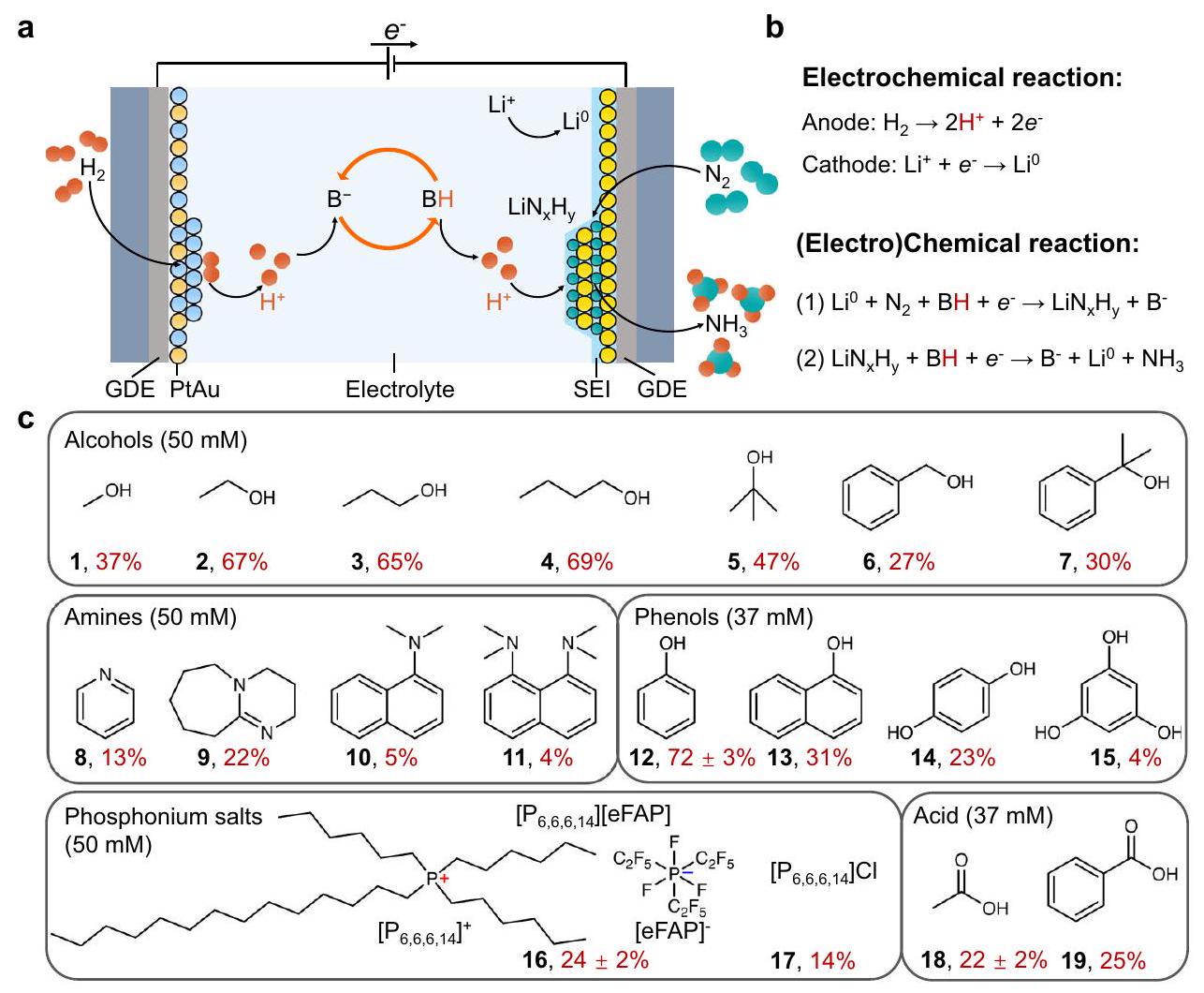
استنادًا إلى هذه المبادئ التصميمية لناقلات البروتونات الفعالة، تم تقييم أداء Li-NRR لفئات مختلفة من ناقلات البروتونات، بما في ذلك الكحوليات، الأمينات، الفينولات، أملاح الفوسفونيم، والأحماض الكربوكسيلية، في إلكتروليت ذو تدفق مستمر تحت نفس الظروف (الشكل 1ج والجدول التكميلي 1). دون إضافة ناقلات بروتونات في الإلكتروليت، تم توليد حوالي من الأمونيا من ترسبات القطب، مما يعني أن ، THF، والشوائب في THF قد تعمل كناقلات بروتونات أضعف نسبيًا. كان الإلكتروليت 1 م من رباعي فلوريد الليثيوم في THF مع 37 مللي مول أو 50 مللي مول من ناقلات البروتونات. أظهر الإيثانول (2) (الأرقام الغامقة تشير إلى الأشكال 1ج)، 1-بروبانول (3)، و1-بيوتانول (4) كفاءة فاراداي عالية نسبيًا، وهو ما يتماشى مع التقارير السابقة . من المثير للاهتمام، لوحظ انخفاض ملحوظ في الكفاءة الفارادائية عند استبدال مجموعات أكبر، كما يتضح من المقارنة بين المركبات 2 و6، وكذلك 5 و7. بالمقابل، فإن الأمينات، مثل البيريدين (8) وإسفنجة البروتون (11)، لديها مجموعة قاعدية، لكنها لا تستطيع بسهولة التبرع أو سحب بروتون. لذلك، تعتبر الأمينات ناقلات سيئة. تم تصنيع أملاح الفوسفونيم (16، [ ][eFAP]) من خلال تفاعل تبادل الأيونات وتم تأكيدها بواسطة مطيافية الرنين المغناطيسي النووي (NMR) (الشكل التكميلي 3). للتخفيف من تأثير الأكسجين والماء على أداء أملاح الفوسفونيم، تم إجراء تجارب Li-NRR داخل صندوق قفازات مملوء بالآرغون . تم ملاحظة نشاط الفوسفونيم
الشكل 1 | فحص ناقلات البروتونات في مفاعل ذو تدفق مستمر. أ عملية نقل البروتونات التخطيطية لتخليق الأمونيا بوساطة الليثيوم في إلكتروليت ذو تدفق مستمر. ب ترسيب الليثيوم عند الكاثود وتفاعل أكسدة الهيدروجين عند الأنود. كفاءات فاراداي للأمونيا لمجموعة متنوعة من ناقلات البروتونات. تم تحديد الكفاءات الفارادائية تجاه الأمونيا لناقلات البروتونات من خلال تمرير شحنة إجمالية قدرها 700 كولوم (على مدى 2.5 ساعة) مع دورة جهد مثالية ( لمدة دقيقة واحدة ثم لمدة دقيقة واحدة) تحت نفس ظروف الاختبار. في تمثل البيانات المتوسط الانحراف المعياري المستمد من ثلاث قياسات مستقلة.
تم ملاحظة أن أملاح (16 و17) كانت أقل من تلك الخاصة بالكحوليات، وهو ما يمكن أن يُعزى إلى صعوبة حمل البروتونات ومعدل الانتشار المنخفض (الشكل التكميلي 4). كما هو متوقع، أظهرت الأحماض (18 و19) نشاطًا أقل بسبب طبيعتها الحامضية العالية. من بين مختلف ناقلات البروتونات التي تم تقييمها، أظهر الفينول (12) أعلى كفاءة فارادائية قدرها في عملية Li-NRR عند استخدامه بتركيز مثالي قدره 37 مللي مول. تجاوز هذا الأداء ذلك الخاص بالإيثانول، الذي حقق أعلى كفاءة فارادائية له عند تركيز مثالي قدره 50 مللي مول. بعد ذلك، ستتركز المزيد من التجارب والنقاشات على دراسة الفينول كناقل بروتون، نظرًا لأدائه الملحوظ في Li-NRR. يجب ملاحظة أن التجارب الكمية لتوسيم النظائر لـ Li-NRR قد تم إجراؤها في أعمالنا السابقة ، وبالتالي، لم يتم عرض تجربة توسييم النظائر في هذا العمل.
التحقق من الفينول كناقل بروتون
كما وجدنا في عملنا السابق، تتطلب حالة دورة الجهد المثالية تطبيق كثافة تيار قدرها لمدة دقيقة واحدة (الجهد المقابل يُشار إليه بجهد الترسيب) ثم لمدة دقيقة واحدة (الجهد المقابل يُشار إليه بجهد الراحة) . تم الحصول على الكفاءات الفارادائية لناقلات البروتونات من خلال تمرير شحنة إجمالية قدرها 700 كولوم تحت حالة دورة الجهد المثالية. كما هو موضح في الشكل 2أ، أظهر قياس الجهد الزمني (CP) لـ PhOH متوسط قيم جهد الأنود والجهد الكاثودي بحوالي 0.7 فولت و -3.6 فولت مقابل Pt، على التوالي. وُجد أن الكفاءة الفارادائية تجاه الأمونيا تعتمد على تركيز PhOH، مع كفاءة فارادائية قدرها عند التركيز المثالي البالغ 37 مللي مول (الشكل 2ب). تنشأ هذه الاعتمادية على التركيز من وجود البروتونات داخل PhOH، والتي تؤثر مباشرة على تركيز البروتون المتاح في نظام Li-NRR (الشكل التكميلي 5). بالمقارنة مع غياب ناقل البروتون، تم توزيع الأمونيا المنتجة باستخدام PhOH بشكل أساسي في الطور الغازي والإلكتروليت، مما يمثل أكثر من من إجمالي الأمونيا المولدة (الشكل 2ج). خلال فترة الراحة التي مدتها دقيقة واحدة عند جهد الدائرة المفتوحة (OCV)، من المتوقع أن يزيد الجهد الراحة للكاثود في منحنى CP بسبب التفاعل بين ناقل البروتونات ومواد سطح الكاثود. كان الجهد الراحة في غياب ناقل البروتونات -3 فولت مقابل Pt، والذي يمكن أن يكون معيارًا لجهد الراحة في وجود ناقل البروتونات (الشكل التكميلي 6). على سبيل المثال، كان الجهد الراحة مع الإيثانول -2 فولت مقابل Pt، ولكن مع حمض الأسيتات، كان -1 فولت مقابل Pt بسبب طبيعته الحامضية العالية (الأشكال التكملية 7 و8). عند مقارنة المركبات 2 و6، 5 و7، 18 و19، وكذلك 12 و13، لوحظت نسبة أعلى من الأمونيا في ترسبات القطب إلى إجمالي الأمونيا (أي، لا يمكن لناقل البروتونات أن يبرتن في الوقت المناسب وتراكم ) عندما يتم استبدال ناقلات البروتونات بمجموعات أكبر (الشكل التكميلي 9). قد تشير هذه النسبة الأعلى إلى قدرة بروتنة أقل لناقل البروتونات، وهو ما ينعكس في اقتراب الجهد الراحة من -3 فولت (أي، لا تذبذب) خلال OCV (الأشكال التكملية 6-8).
لتقديم مزيد من الأدلة على قدرة ناقل البروتونات على نقل البروتونات في عملية Li-NRR الفعلية، نقترح إجراء يتضمن استخدام الشكل المنزوع البروتونات () من ناقل البروتون لتقييم قدرته على نقل البروتونات. بالإضافة إلى ذلك، عندما تم تحديد أنجح ناقل بروتون، نقترح استخدام مطيافية الكتلة المعززة بالمت isotopes (أي، تفاعل أكسدة الديوتيريوم) لتأكيد أن الهيدروجين الموجود في الأمونيا المنتجة يأتي من تفاعل أكسدة الهيدروجين. أولاً، تم استبدال الفينول (PhOH) بالفينوكسييد الليثيوم (PhOLi) لتقييم أدائه في عملية Li-NRR. توضح الشكل 2d قدرة PhOLi، حيث يظهر أن جهد الأنود والكاتود متوافقان مع تلك الموضحة في الشكل 2a. خلال الدقائق العشر الأولى من القدرة (الشكل 2d)، تم تغيير جهد الأنود والكاتود، وهو ما يمكن أن يُعزى إلى الانخفاض النسبي في
الشكل 2 | أداء تخليق الأمونيا بوساطة الليثيوم باستخدام الفينول أو فنيكوكسي الليثيوم كناقلات بروتون. أ قياس الجهد الزمني باستخدام الفينول كناقلات بروتون (37 مللي مول). ب كفاءة فاراداي تتغير مع تباين تركيزات الفينول. ج تؤثر تركيزات الفينول المختلفة على توزيع الأمونيا المنتجة في الإلكتروليت، والطور الغازي، وترسبات الأقطاب.الكرونوپوتنشيومترية باستخدام فنوكسييد الليثيوم كناقلات بروتون (37 مللي مول). تغيرت الكفاءة فاراداي مع تباين تركيزات الفينوكسي الليثيوم.ال تؤثر تركيزات مختلفة من فنوكسييد الليثيوم على توزيع الأمونيا المنتجة في الإلكتروليت، والغاز، وترسبات الأقطاب. جميع الجهود بدون تصحيح iR. حالة دورة الجهد هي لمدة دقيقة واحدة و لمدة دقيقة واحدة. اجتاز جميع التجارب شحنة إجمالية قدرها 700 كولوم عند كثافة تيارمع نفس حالة الدورة المحتملة. تمثل أشرطة الخطأ المتوسطالانحراف المعياري المستمد من ثلاثة قياسات مستقلة. تركيز البروتون في المراحل المبكرة. لقد ثبت أن تركيبة تدفق الغاز وتركيبة الإلكتروليت يمكن أن تؤثر على استقرار الجهد الكهربائي لقطب الإشارة الزائفة من البلاتين.تمت ملاحظة ظاهرة مماثلة باستخدام إيثوكسيد الليثيوم (EtOLi) في عملية LiNRR (الشكل التكميلي 10). على عكس PhOH، كانت كفاءة الأمونيا مستقلة عن تركيز PhOLi (الشكل 2e)، مما أشار إلى أن تركيز البروتون المتاح في الإلكتروليت كان محدودًا فقط بكثافة التيار لعملية HOR. ومن المRemarkably، كانت كفاءةتم تحقيقه عند تركيز PhOLi يبلغ 50 مللي مول، والذي اقترب بشكل كبير من الأداء الذي تم تحقيقه عند التركيز الأمثل لـ PhOH. هذه النتائج تعتبر دليلاً مباشراً على أن الشكل المنزوع البروتون لـتعمل الأيونات كوسيلة لنقل البروتونات في عملية تقليل النيتروجين في الليثيوم. عند استخدام PhOLi، تكون توزيع الأمونيا في الطور الغازي أقل مقارنة باستخدام PhOH (الشكل 2f)، وهو ما يمكن أن يُعزى إلى الخصائص المختلفة لطبقة واجهة الإلكتروليت الصلبة (SEI) أو ترسبات الأقطاب.
لكشف الفرق في ترسبات SEI والقطب بين PhOH و PhOLi (الأشكال التكميلية 11 و 12)، تم إجراء تجارب خلية تدفق في صندوق قفازات مملوء بالغاز الأرجون تحت أربعة ظروف – أي، بعد اختبار الفولتامترية المسحية الخطية (LSV) مع إما PhOH أو PhOLi وبعد 700 كولوم من CP مع إما PhOH أو PhOLi. تم استخدام أنظمة نقل المجهر الإلكتروني الماسح (SEM) ، حيود الأشعة السينية (XRD) ، ومطياف الأشعة السينية للألكترونات (XPS) لتجنب التعرض للهواء والرطوبة (الأشكال التكميلية 13-15). تكشف صور SEM عن تشكيل طبقة SEI كثيفة بعد اختبار LSV مع PhOH، بينما لوحظت ترسبات أقل مع PhOLi (الشكل التكميلية 16). بعد إجمالي شحنة قدرها 700 كولوم في اختبار CP، أظهر سطح الكاثود لـ PhOLi طبقة غير منتظمة وأسمك من الترسبات، بينما لوحظت طبقة موحدة وأرق من الترسبات عند استخدام PhOH (الأشكال التكميلية 17 و 18). بالمقارنة مع PhOH، أظهر استخدام PhOLi كوسيلة لنقل البروتونات مستوى أعلى. كثافة الكتلة للترسبات الكاثودية والترسبات السميكة للقطب (الأشكال التكميلية 19-21). قد تكون هذه الاختلافات عوامل مساهمة في الانخفاض الملحوظ لوجود الأمونيا في الطور الغازي عند استخدام PhOLi كوسيلة لنقل البروتون (الشكل 2f). أكدت أنماط حيود الأشعة السينية (XRD) أن المكون الرئيسي لترسبات القطب هو فلوريد الليثيوم (LiF) بعد 700 درجة مئوية من اختبار CP مع PhOH أو PhOLi (الأشكال التكميلية 22 و23). كما أكدت طيف XPS الخاص بتحديد العمق أن LiF كان النوع السائد الموجود في كل من SEI وترسبات القطب عند استخدام PhOH أو PhOLi، مما يتماشى مع النتائج السابقة (الأشكال التكميلية 24-29).. بعد 700 درجة مئوية من اختبار CP مع PhOH أو PhOLi، يُنسب ذروة N 1s عند 398 إلكترون فولت إلى (الأشكال التكميلية 28 و 29).
تعد مطيافية الكتلة المعلمة بالنظائر في حالة التشغيل تجربة ضرورية أخرى للإجراء المقترح لإثبات القدرة على نقل البروتون من ناقل البروتون. تم إجراء مطيافية الكتلة في حالة التشغيل في مفاعل تدفق مستمر، حيث تم استخدام الديوتيريوم (حدثت تفاعل الأكسدة على جانب الأنود لتوليد البروتونات) لفحص ما إذا كان ناقل البروتون (PhOH) يمكنه نقل البروتونات إلى منتجات الكاثود (الشكل 3). تم قياس المنتجات التي تحتوي على الديوتيريوم (D) والهيدروجين (H) على جانب الكاثود باستخدام مطيافية الكتلة أثناء التشغيل (الشكل التكميلية 30). في البداية، يكون الكاثود محاطًا بإلكتروليت جديد، مما يؤدي إلى هيمنة المنتجات المحتوية على H مثل و (الشكل 3ب). كما هو متوقع، مع تقدم التجربة، تم إنتاج المزيد والمزيد من المنتجات المحتوية على الديوتيريوم، مما أدى في النهاية إلى هيمنة الأمونيا المخصبة بالكامل بالديوتيريوم. ) (الشكل 3ج). تظهر تلك النتائج بشكل قاطع قدرة PhOH على نقل البروتونات، حيث تنقل البروتونات من HOR إلى منتجات الكاثود. في المرحلة الأولية، يكون PhOH متمعدنًا بالكامل مع H، مما يؤدي إلى توليد منتجات تحتوي على H. عندما تكون في الشكل غير المتمعدن () يتشكل، يمكن أن يتم إعادة بروتنة المزيد من قبل (الشكل التوضيحي 31). بعد ذلك، يمكن لـ PhOD بروتنة نيتريدات الليثيوم لتوليد الأمونيا المحتوية على D.
لتوضيح قدرة الشكل المنزوع البروتون (“) للتفاعل مع البروتونات خلال عملية Li-NRR، تم إجراء طيف الرنين المغناطيسي النووي (NMR) للسوائل الكهربائية قبل وبعد اختبار الكيمياء الكهربائية (الأشكال التكميلية 32 و33). كما هو موضح في الشكل 4a، الشكل المنزوع البروتون () يعمل كمتقبل للبروتون، مما يؤدي بشكل فعال إلى بروتنة البروتونات الناتجة عن HOR لتكوين PhOH. بعد ذلك، يتفاعل PhOH مع لإطلاق الأمونيا وتجديد الشكل غير البروتوني (). الـ
الشكل 3 | قياس الطيف الكتلي أثناء التشغيل لمنتجات غاز الأمونيا الكاثودية مع الديوتيريوم المعلم باستخدام الفينول كوسيلة لنقل البروتون. أ قياس الجهد الزمني باستخدام الفينول كوسيلة لنقل البروتون. ب قياس غاز الأمونيا في الطور الغازي عند حدوث تفاعل أكسدة الديوتيريوم في الأنود. ج الكميات النسبية المقاسة المقابلة من الأمونيا المحتوية على D أو المحتوية على H.
طيف NMR لـ PhOLi و PhOH قبل اختبار الكيمياء الكهربائية هو معيار لتحليل NMR (الشكل 4b والشكل التكميلية 34). التحول الطفيف لـكانت قمم NMR لـ PhOH قبل وبعد اختبار الكيمياء الكهربائية (الشكل التكميلي 34) نتيجة للاختلافات الطفيفة في الرقم الهيدروجيني (أي، بعد الاختبار تم إنتاج الأمونيا). تشير قياسات NMR الكمية إلى أن كمية PhOH تبقى تقريبًا دون تغيير بعد اختبار الكيمياء الكهربائية (الشكل التكميلي 35). وهذا يشير إلى أن PhOH مستقر نسبيًا تحت الظروف التجريبية ولا يتعرض لتحلل أو استهلاك كبير خلال عملية Li-NRR. ومن الجدير بالذكر أنه بعد اختبار الكيمياء الكهربائية، لوحظ أن جميع PhOLi تقريبًا تتحول إلى PhOH من خلال البروتنة (الشكل 4c). تشير هذه التحويلة من PhOLi إلى PhOH إلى القدرة الفعالة على نقل البروتونات لـ PhOLi خلال عملية LiNRR. مجتمعة، توفر مجموعة التجارب التي تم إجراؤها، بما في ذلك فحص قدرة نقل البروتونات لـ PhOLi في عملية Li-NRR الحقيقية، وقياس الطيف الكتلي المعلم بالنظائر أثناء التشغيل، وتحليل NMR، دليلًا لا لبس فيه على قدرة نقل البروتونات لـ PhOH.
الصيغة المنزوعة البروتون من ناقل البروتون كعازل بروتون
علاوة على ذلك، عندما تم استخدام حمض الأسيتيك كوسيلة لنقل البروتونات، كانت كفاءة إنتاج الأمونيا فقط“، ويرجع ذلك أساسًا إلى الزيادة الملحوظة في حدوث تفاعل الهيدروجين التنافسي (الشكل التكميلي 36). عندما يتم خلط PhOLi (37 مللي مول) مع حمض الأسيتيكتم استخدامه كوسيلة نقل البروتون، وتحسن الجهد الكهربائي نحو الأمونيا إلى (الشكل التوضيحي 37). عند إضافة كمية مكافئة من PhOLi، حدثت فقط نسبة ضئيلة من تحول PhOLi إلى PhOH (الشكل التوضيحي 38). ومع ذلك، لوحظ انخفاض كبير في تيار HER (الشكل التوضيحي 36). تشير هذه النتائج إلى قدرة PhOLi على تخزين البروتونات. لذلك، تحسن الأداء (حوالي يمكن أن يُعزى ذلك إلى قدرة PhOLi على تخزين البروتونات (أي، تقليل تركيز البروتونات المتاحة في الإلكتروليت)، مما يخفف بشكل فعال من الآثار السلبية لتفاعل الهيدروجين التنافسي (الشكل التكميلي 36).
استقرار الشكل المنزوع البروتون لنقل البروتون
أحد المتطلبات الأساسية لوجود ناقل بروتون فعال هو أن الشكل المزيل للبروتون من ناقل البروتون يجب أن يظهر كلا من
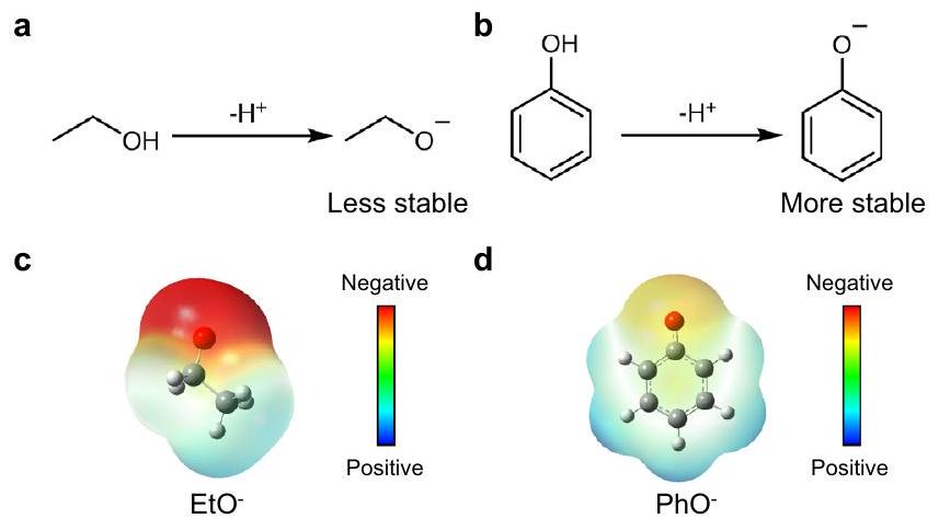
الشكل 4 | عرض لقدرة الفينول على نقل البروتونات. أ رسم تخطيطي لعملية نقل البروتونات للفينول في تخليق الأمونيا بوساطة الليثيوم. الـ طيف الرنين المغناطيسي النووي لليثيوم فينوكسايد في التتراهيدروفوران قبل الكيمياء الكهربائية اختبار. جطيف NMR للسوائل الكهربائية بعد التفاعل باستخدام فنيليد الليثيوم كوسيلة لنقل البروتون بعد اختبار الكيمياء الكهربائية (700 درجة مئوية من CP). استقرار كهربائي كيميائي ممتاز واستقرار كيميائي خلال عملية LiNRR. اخترنا الإيثانول المتطور كمرجع لمقارنة الاستقرار. توضح الأشكال 5أ و5ب تفاعلات إزالة البروتون للإيثانول والفينول، على التوالي. من المعروف أن أيون الفينوكسايد المستقر بال resonance أكثر استقرارًا من أيون الإيثوكسيد.، كما يتضح من خرائط الجهد الكهروستاتيكي الناتجة عن حسابات نظرية الكثافة الوظيفية (DFT) (الشكل 5c، d)، حيث توجد شحنة سالبة أقل على ذرة الأكسجين في الفينوكسايد، مقارنةً بالإيثوكسايد. عندما تم استخدام إيثوكسايد الليثيوم (EtOLi) كوسيلة لنقل البروتونات، كانت الكفاءة المحققة فقط (الشكل التوضيحي 39)، أقل بكثير من ذلك الخاص بـ PhOLi (قد يُعزى الأداء المنخفض لـ EtOLi إلى الاستقرار النسبي الأقل لأيون الإيثوكسيد مقارنةً بأيون الفينوكسايد (الأشكال التكميلية 35 و40). تم التحقيق في الاستقرار الكهروكيميائي لـ EtOH وPhOH في إلكتروليت مائي (الشكل التكميلية 41). كشفت إمكانيات الأكسدة الابتدائية والذروة عن ترتيب استقرار متميز تحت نفس الظروف التجريبية: أظهر PhOH استقرارًا متفوقًا مقارنةً بـ EtOH وTHF، وهو نتيجة تتماشى مع الدراسات السابقة.من الجدير بالذكر أن كثافة تيار الأكسدة لـ PhOH كانت أقل بكثير من تلك الخاصة بـ EtOH، مما يدل على استقرار كهربائي ممتاز. تؤكد هذه النتائج على استقرار PhOH كوسيلة فعالة لنقل البروتونات في عملية Li-NRR العملية.
تشير الحسابات الديناميكية الحرارية إلى أنه، على الجانب الكاثودي، جميع الخطوات الكهروكيميائية لتقليل النيتروجين (NRR) مواتية من الناحية الطاقية أثناء التشغيل.بينما يكون HOR انتقائيًا للغاية على أنود PtAu اعتمادًا على ما إذا كان الإيثانول أو الفينول هو الناقل.
الشكل 5 | استقرار الشكل المنزوع البروتون لوسائط البروتون. أ ب تفاعل منزوع البروتون للإيثانول (أ) والفينول (ب). ج، د خريطة الجهد الكهروستاتيكي لأيون الإيثوكسيد (ج) وأيون الفينوكسايد (د).
(الشكل التوضيحي التكميلي 42). لذلك، نقوم بإدخال تفاعل أكسدة الهيدروجين (HOR) كعملية أنودية في نموذج نقل الكتلة، استنادًا إلى نموذجنا السابق للذرات الحركية.“، من خلال تحويل مباشر بين كثافة التيار وتدفق البروتون من تفاعل الهيدروجين (للتفاصيل انظر قسم “الطرق الحسابية”). ثم استخدمنا نموذج نقل الكتلة لمحاكاة نظام Li-NRR استنادًا إلى حقيقة أن الانتشار و أبطأ بشكل ملحوظ من حركيات التفاعل ومحدد بمعدل التفاعل بشكل عام. النموذج، الذي يعتمد على النموذج وتم توسيعه ليشمل التفاعلات المتجانسة في الإلكتروليتاتيتم وصفه بالتفصيل في “طرق الحوسبة”، مما يظهر توافقًا عامًا مع البيانات التجريبية (الشكل التكميلي 43)مساهمًا في فهم معقول للعلاقة الشبيهة بالبراكين لتركيزات نقل البروتونات مقابلالانتقائية، وتوقع الاتجاه المتغير للأداء الأمثل عند التوازن بين مقابل التدفق. يعتمد الأخير على تركيزات ناقلات البروتون والأنواع. في حالة الناقلات الحمضية ذات المستوى الأدنىعلى سبيل المثال، حمض الأسيتيك، يكون من الأسهل بكثير نقل البروتون من الأنود إلى الكاثود من خلال البروتنة وإزالة البروتون، مما يؤدي إلى قيمة أكبر لتدفق البروتون عند نفس التركيز، وبالتالي زيادة في الكفاءة الكاملة للأمونيا في-منطقة محدودة وانخفاض في FE في-منطقة محدودة، كما هو موضح في الشكل 6a. الشكل المنزوع البروتون ()، غير قادر على المساهمة في تركيز البروتونات في الإلكتروليتات، يمكن أن يحتفظ بالأداء الأمثل عند زيادة التركيز (الشكل التكميلي 44)، متفقًا مع الملاحظة التجريبية (الشكل 2e). عند تركيز معين من ناقل البروتون مثل إعدادنا التجريبي، سيكون بإمكان مخطط البركان الجديد (الشكل التكميلي 45) توضيح تأثيرات ناقل البروتون..
تقييم دقيق لـفي THF من الضروري قياس تأثير نقل البروتون. قمنا بتطبيق DFT المصحح بالمذيب لتحديد المعايير.الحساب (الشكل التوضيحي التكميلي 46) لسلسلة من الكحوليات والأحماض. تظهر نتائج الحساب (الجدول التكميلي 2) توافقًا جيدًا مع الأدبيات وتوسع القدرة علىمجموعات البيانات في المذيبات العضويةأخذت المحسوبفي نموذج النقل الكتلي، وجدنا أن الوصف الفردي،لا يمكن أن تفسر تمامًا تأثير ناقلات البروتون على تقليل النيتروجين في الليثيوم (الشكل التكميلي 47). كمثال، هناك استثناء وهو الفينول و1-نافثول اللذان لهما تشابه كبير.القيم (29.24 مقابل 29.70)، ولكن هناك فرق كبير في أداء NRR FE ( مقابل ). بالنظر إلى الفرق في الحجم بين الفينول و 1-نافثول، يمكن للمرء أن يفترض diffusivity المرتبطة بالحجم لشاتل البروتون، كالوصف الثاني للأداء التحفيزي. عند نقطة معينة القيمة، فإن ناقل البروتون ذو الانتشار المنخفض سيكون، في نفس الوقت، لديه انتشار بروتون أبطأ، مما يتطلب تعويضًا من خلال زيادة تركيزه (الشكل التكميلي 48). التأثيرات التآزرية لـ وانتشارها على FE الناتج ممثلة رسوميًا في الشكل 6ب، حيث يوجد كان سيفعل
الشكل 6 | اعتماد أداء Li-NRR على ومعامل انتشار ناقلات البروتون. رسم بياني ثنائي الأبعاد لكفاءة فاراداي للأمونيا مقابل تركيزات ناقل البروتون مع اختلافات في خريطة حرارية للتنبؤ بـ
يتطلب إما ناقلات بروتون حمضية ولكن محدودة النقل أو ناقلات بروتون قاعدية ولكن سريعة النقل، بما يتماشى مع الاكتشافات التجريبية. التوازن بين الانتشار و هو تجسيد لـ التدفق، لا يزال يتماشى مع نموذج نقل الكتلة الأصلي لدينا.
باختصار، تم إجراء فحص نقل البروتونات في عملية Li-NRR العملية مع HOR عند الأنود في مفاعل تدفق مستمر. تلعب ناقلات البروتونات دورًا حاسمًا في نقل البروتونات من HOR عند الأنود إلى الكاثود لتخليق الأمونيا في عملية Li-NRR. نقترح إجراءً عامًا للتحقق من فعالية ناقلات البروتونات في Li-NRR وتأسيس مبادئ التصميم لتطوير ناقلات بروتون فعالة في عمليات Li-NRR العملية. من خلال هذا الإجراء، نوضح أن PhOH أظهر قدرات ممتازة في نقل البروتونات واستقرارًا في عملية Li NRR. علاوة على ذلك، أظهر PhOH نسبة كفاءة عالية في إنتاج الأمونيا تصل إلى“، وهو من بين أعلى انتقائية الأمونيا التي تم تحقيقها في اختزال النيتروجين في الليثيوم في الظروف المحيطة. الشكل المنزوع البروتون () من PhOH ثبت أنه يعمل كالكائن الرئيسي المسؤول عن نقل البروتونات خلال عملية Li-NRR. توفر مجموعة من الحسابات النظرية والنمذجة الدقيقة فهمًا لآلية نقل البروتونات في عملية Li-NRR. تسهم النتائج في فهم الجوانب الآلية ومبادئ التصميم لوسائل نقل البروتونات الفعالة في التطبيقات العملية لـ Li-NRR، مما يمهد الطريق في النهاية لتطوير طرق إنتاج الأمونيا المستدامة والصديقة للبيئة.
طرق
المواد
تم استخدام جميع المذيبات والمواد الكيميائية كما هي دون مزيد من التنقية ما لم يُذكر خلاف ذلك. قماش الفولاذ المقاوم للصدأ 316 (McMaster-Carr،شبكة، حجم المسام316 قماش الفولاذ المقاوم للصدأ (McMaster-Carr،شبكة، حجم المسامسلك البلاتين (جودفيلو،، القطر: 0.5 مم ) (سيغما-ألدريتش، كاشف ACS) (سيغما-ألدريتش، ) ، (سيغما-ألدريتش، 99.999%)، تتراهيدروفوران (THF، سيغما-ألدريتش، خالي من الماء، >99.9%، خالي من المثبطات)، (سيغما-ألدريتش، اللامائية)، الإيثانول (EtOH، هوني ويل، اللامائية)، إيثوكسيد الليثيوم (EtOLi، سيغما-ألدريتش، 95%)، الميثانول (سيغما-ألدريتش، )، 1-بروبانول (سيغما-ألدريتش، 1-بيوتانول (سيغما-ألدريتش، 99.9%)، تيرت-بيوتانول (سيغما-ألدريتش، خالي من الماء، )، كحول بنزيل (سيغما-ألدريتش، خالي من الماء، 99.8%)، 2-فينيل-2-بروبانول (سيغما-ألدريتش، 97%)، بيريدين (سيغما-ألدريتش، خالي من الماء، 99.8%)، 1،8-ديازابيسكلو[5.4.0]أوندك-7-ين (DBU، سيغما-ألدريتش، ن،ن-ثنائي ميثيل-1-نافثيل أمين (NDN، سيغما-ألدريتش،ن,N,N’,N’-تترا ميثيل-1,8-نافثالينديامين (إسفنجة بروتون، سيغما-ألدريتش، )، الفينول (PhOH، سيغما-ألدريتش، 1 م من فنوكسييد الليثيوم في محلول THF (PhOLi، أصفر فاتح، سيغما-ألدريتش)، 1-نافثول (سيغما-ألدريتش،الهيدروكينون (سيغما-ألدريتش،فلوغلوكسينول (سيغما-ألدريتش،حمض الأسيتيك (سيغما-ألدريتش،حمض البنزويك (سيغما-ألدريتش،كلوريد ثلاثي هكسيل تيترا ديسيل فوسفونيم (سيغما-ألدريتش،1-إيثيل-3-ميثيلبيروليدينيوم ثلاثي (بنتافلوروإيثيل) ثلاثي فلوروفوسفات (سيغما-ألدريتش، نقاء عالي)، ثنائي كلور الميثان (دي سي إم، سيغما-ألدريتش، ).
10.4 جرام من 1-إيثيل-3-ميثيلبيروليدينيوم ثلاثي (بنتافلوروإيثيل) ثلاثي فلوروفوسفات ) و 11.1 جرام من كلوريد ثلاثي هيكسيل تيترا ديسيل فوسفونيم ( ) أُضيفت إلى خليط من الماء ) وثنائي كلورو ميثان (DCM). تم تحريك المزيج بقوة لمدة ساعة واحدة في درجة حرارة الغرفة. بعد التفاعل، تم غسل محلول DCM العضوي بماء موليQحوالي 10 مرات حتى أظهر اختبار كلوريد الفضة عدم وجود رد فعل. بعد التنقية، تم إزالة DCM في فراغ عندعلى جهاز التبخر الدوار. تم إزالة الماء المتبقي عن طريق إذابة المادة الناتجة في البنزين وتقطيرها تحت فراغ عندبعد التنقية، تم ترك المركب الناتج ذو اللون الأصفر الفاتح ليجف في الفرن عندلمدة لا تقل عن ليلة واحدة أو على مدار عطلة نهاية الأسبوع. الـ، و أظهر التحليل الطيفي بالرنين المغناطيسي النووي (NMR) منتجًا نقيًا دون وجود مادة ابتدائية أو تلوث. كانت نسبة العائد من التفاعل هي.
توصيف المواد
تم استخدام حيود الأشعة السينية (XRD) وطيفية الإلكترونات الضوئية بالأشعة السينية (XPS) والمجهر الإلكتروني الماسح (SEM) لوصف الأقطاب وودائع أقطاب الكاثود. لتحليل واجهة الإلكتروليت الصلبة (SEI، بعد LSV) أو الأقطاب بعد التفاعل (ودائع الأقطاب، بعد 700 درجة مئوية)، تم وصف أقطاب WE بعد الكيمياء الكهربية باستخدام XRD وXPS وSEM. تم إجراء تجارب خلية التدفق في صندوق قفازات مملوء بالآرغون وتم استخدام نظام نقل لتقليل التعرض للهواء. بالنسبة لـ XRD، تم استخدام قبة بولي كربونات (PC) محكمة الغاز (Anton Paar) لتغطية العينة فوق حامل عينة XRD أثناء النقل من صندوق القفازات إلى الجهاز وكذلك أثناء القياس. بالنسبة لـ XPS، تم نقل العينات من صندوق القفازات إلى XPS عبر نظام نقل فراغي. تم نقل عينات SEM من صندوق القفازات إلى SEM عبر قضيب نقل cryo-SEM. تم تسجيل بيانات XRD باستخدام برنامج Data Collector v5.4 على جهاز حيود الأشعة السينية Malvern Pananalytical Empyrean. على مسار الشعاع الساقط، تم استخدام مرآة أشعة سينية متوازية لإشعاع النحاس مع قناع ثابت بحجم 10 مم وشَقّ موضوع على بُعد 140 مم من العينة. كانت مسار الشعاع المنكسر مزودًا بمحدد صفائح متوازية له فتحة من. المصدر كان بندقية إمبيريان Cu LFF HR تعمل عند 45 كيلوفولت و 40 مللي أمبير، مع وفلتر ني بيتا. تم تحليل البيانات باستخدام HighScore Plus v4.6a من Panalytical مع أنماط مرجعية من قاعدة بيانات هياكل البلورات غير العضوية (ICSD). تم إجراء مطيافية الإلكترونات الضوئية باستخدام جهاز ThermoScientific Thetaprobe المزود بمصدر أشعة كايل أل.مصدر الأشعة السينية مع ضغط قاعدة الحجرة أقل منتم تسجيل طيف المسح مع 50 مسحًا في وقت إقامة قدره 50 مللي ثانية لكل خطوة 1 إلكترون فولت. تم تسجيل طيف التفاصيل العنصرية معت scans بخطوات 0.1 إلكترون فولت مع وقت إقامة قدره 50 مللي ثانية. كانت الدقة الجانبية وتم رفع ضغط الغرفة إلى عن طريق تدفق غاز الأرجون 6.0 حسب الحاجة باستخدام مسدس الفيض، الذي تم استخدامه في وضع تحييد الشحنة أثناء القياس. تم جمع البيانات وتحليلها باستخدام برنامج Thermo Advantage v5.9917 من شركة Thermo Fischer Scientific. تم ملاءمة جميع البيانات باستخدام خوارزمية الملاءمة باول وتم تحديد الخلفية باستخدام خيار الخلفية الذكي، الذي يعتمد على خلفية شيرلي.
تحضير أقطاب الكاثود
قماش الفولاذ المقاوم للصدأ 316 (SSC، مكماستر-كار)شبكة، حجم المسام من ) تم استخدامه كأقطاب كاثودية لاختبار تخليق الأمونيا الكهروكيميائي. قبل الاستخدام، تم تنظيف SSC باستخدام الأسيتون والإيثانول 3 مرات. تم تجفيف SSC المعالج في فرن مفرغ لمزيد من الاستخدام.
تحضير أقطاب الأنود
تم تحضير PtAu/SSC عن طريق الترسيب الكهربائي كما تم وصفه سابقًا. وصف موجز لعملية الترسيب الكهربائي، SSC بحجم مسام (مكماسير-كار، ) تم استخدامه كقطب عمل، واثنان من أقطاب شبكة البلاتين (جودفيلو، ) كانت متصلة كهربائياً واستخدمت كقطب مضاد مقسم. الـ (سيغما-ألدريتش، كاشف ACS) مع (سيغما-ألدريتش، ) في (سيغما-ألدريتش، ) تم استخدام المحلول كإلكتروليت لترسيب PtAu/SSC. كثافة التيار تم تطبيقه لمدة دقيقتين حيث حدث تطور مكثف للهيدروجين والمعادن تمت عملية الترسيب في نفس الوقت، مما أدى إلى هياكل ذات مساحة سطح عالية من PtAu على SSC. بعد الترسيب الكهربائي، تم شطف الأقطاب في الإيثانول والماء النقي للغاية.المقاومية، ميلليبور، نظام Synergy UV) عدة مرات لإزالة الإلكتروليتات المتبقية.
التجارب الكهروكيميائية
تم إجراء تخليق الأمونيا الكهروكيميائي في خلية تدفق ذات ثلاث غرف (الشكل التوضيحي 1). كانت المساحة الفعالة للقطب الكهربائي في خلية التدفق هيغرفة الإلكتروليت المركزية مصنوعة من بولي إيثر إيثر كيتون (PEEK، مواد مقاومة لـ THF). (5.0، إير ليكيد) و تم التحكم في معدلات تدفق الغاز (5.0، إير ليكيد) باستخدام جهاز التحكم في التدفق الكتلي (بروكس إنسترومنت) وتم ضبطها على 75 سم³/دقيقة. و تم تنظيف المواد المستخدمة في التجارب بواسطة أجهزة تنقية (NuPure) لتقليل المركبات المحتوية على النيتروجين القابلة للتغيير إلى مستوى أجزاء في التريليون من حيث الحجم (ppt-v). قبل كل تجربة، تم غلي أجزاء خلية التدفق في ماء نقي للغاية لمدة 3 ساعات وتجفيفها طوال الليل فيفي فرن. الـ SSC المنظف (شبكة، سمك: ) تم استخدامه كالكاثود (WE، القطب العامل). تم استخدام PtAu/SSC المحضر حديثًا كأنود (CE، القطب المضاد). كان القطب المرجعي الزائف (RE) سلكًا من البلاتين (Goodfellow، 99.99%، القطر: 0.5 مم). قبل الاختبارات الكهروكيميائية، تم تسخين سلك البلاتين بالنار.
ال (سيغما-ألدريتش، خالي من الماء) تم تجفيفه عند لمدة 48 ساعة في فرن مفرغ قبل الاستخدام. تم تجفيف الإيثانول (هوني ويل، خالي من الماء) بـالمناخل الجزيئية. كانت محلول الإلكتروليت يتكون منفي التتراهيدروفوران (THF، خالي من الماء،خالية من المثبطات، سيغما-ألدريتشتم تحضيرها في صندوق قفازات مملوء بالارجون. تم استخدام مضخة حقن (World Instruments) للتحكم في معدل تدفق الإلكتروليتات عند. كانت الحقنة (Trajan Scientific and Medical، 100 مل) تتكون من أنبوب زجاجي بوروسيليكات ومكبس PTFE (محكم الغاز). تم استخدام محلول مائي بتركيز 1 مللي مول من HCl (Sigma-Aldrich، Suprapur) للتحكم في ضغط العودة وحبس غاز الأمونيا. تم تعديل ضغط العودة في مخرج الغاز لخلية التدفق بواسطة عمود محلول HCl بتركيز 1 مللي مول بطول 10.5 سنتيمتر.، مما يؤدي إلى تدرج ضغط قدره 15 ملبار بين مدخل الغاز ومخرج خلية التدفق. قبل حقن الإلكتروليت في غرفة الإلكتروليت، يتم تنقية و تم إدخالها في خلية التدفق المجمعة الفارغة لمدة 30 دقيقة على الأقل. بعد ذلك، تم حقن محلول الإلكتروليت في الخلية في و الجوّيات.
تم إجراء تجارب الكيمياء الكهربائية باستخدام جهاز قياس الجهد الكهربائي BioLogic (VMP2). تم قياس المقاومة بين القطب العامل (WE) والقطب المرجعي (RE) باستخدام تقنية طيف الامتصاص الكهربائي بالجهد الثابت (PEIS) وتقنية انقطاع التيار. تم تسجيل قياس الجهد الخطي (LSV) من جهد الدائرة المفتوحة (OCV) حتى يتم رؤية ترسيب الليثيوم بوضوح. بعد ذلك، تم قياس الجهد الزمني (CP) مع دورات الجهد. تشير دورات الجهد إلى أن (الجهد المقابل المسمى جهد الترسيب) تم تطبيقه لمدة دقيقة واحدة ثم (الجهد المقابل الذي يُشار إليه بالجهد الساكن) لمدة دقيقة واحدة. تم تمرير 0.700 كولوم من الشحنة لكل تجربة لتحديد كفاءة فاراداي للأمونيا (FE). نلاحظ أن جميع التجارب أُجريت في درجة حرارة الغرفة وضغط 1 بار. عادةً، كانت تجارب خلية التدفق تُجرى في خزانة تهوية. لتحليل الرواسب على القطب العامل، تم تشغيل خلية التدفق في صندوق قفازات مملوء بالآرجون. نظرًا لأن أملاح الفوسفونيم حساسة لمحتوى الماء، تم إجراء تجارب نقل البروتون باستخدام أملاح الفوسفونيم في صندوق قفازات مملوء بالآرجون. تم قياس محتوى الماء في الإلكتروليت بواسطة تيتريشن كارل فيشر (831 KF كولومتر و728 خلاط، متروهم). قبل اختبار الكيمياء الكهربائية، كان محتوى الماء في الإلكتروليت مع أملاح الفوسفونيم حوالي. عندما انتهى التجربة، الإجماليتم قياس الإنتاج من (1) الطور الغازيمحاصر في 1 مللي مول من HCl، (2)محاصر في الإلكتروليت، و(3)محبوس في رواسب الأقطاب. عادةً،تم استخدام ماء نقي للغاية لذوبان القطب الكهربائي الودائع لإطلاق المحتجز. نلاحظ أن يمكن أن يتفاعل مع المركبات المحتوية على النيتروجين (على سبيل المثال، ) في ترسبات القطب لإنتاج .
تجارب أكسدة THF و EtOH و PhOH في إلكتروليت مائي
يجب أن يتمتع ناقل البروتون الجيد باستقرار كيميائي كهربائي عالي خلال عملية Li-RR. لتقييم الاستقرار الكيميائي الكهربائي لـ THF و EtOH و PhOH على محفزات الأنود PtAu، تم إجراء تجارب الأكسدة في إلكتروليت مائي في خلية زجاجية ثلاثية الأقطاب مصنوعة خصيصًا باستخدام طريقة القطب الدوار.تم معايرة القطب المرجعي قبل اختبار الكيمياء الكهربائية. تم استخدام سلك بلاتيني كقطب مضاد. القطب العامل ( ) تم الحصول عليها من ترسيب كهربائي لـ PtAu على دعامة من التيتانيوم ( ). لتحضير قطب PtAu/Ti، يتم استخدام إلكتروليت من (سيغما-ألدريتش، كاشف ACS) مع (سيغما-ألدريتش، ) في (سيغما-ألدريتش، 99.999%) تم استخدامه. كثافة التيار تم تطبيقه لمدة دقيقتين حيث حدث تطور مكثف للهيدروجين وترسيب المعادن في نفس الوقت بسرعة 2500 دورة في الدقيقة. تم تسجيل منحنى الفولتمترية الدورية (CV) بين 0 و 1.2 فولت مقابل RHE عندفي حالة تشبع بالـ Arتم تقييم نشاط أكسدة THF و EtOH و PhOH في محلول مشبع بالآر بتركيز 0.1 م.مع إلكتروليت 0.1 م THF أو 0.1 م EtOH أو 0.1 م PhOH بمعدل مسح.
تجربة الأكسدة عبر مطيافية الكتلة على الإنترنت
تم جمع قياسات مطيافية الكتلة (MS) باستخدام جهاز QMG 422، مع فلتر الكتلة الرباعي QMA 120 بطول 100 مم من بالزرز. تم تحسين QMS لقياسات التأين اللين عند طاقة تأين تبلغ 26 إلكترون فولت، مما يضمن الحد الأدنى من أنماط التكسير في طيف الكتلة، مع السماح بإشارة جيدة. يتم عرض الإعداد التجريبي بشكل تخطيطي في الشكل التكميلية 30. يتم وضع MS في الاتجاه السفلي علىيتدفق من جانب الكاثود في خلية التدفق. وهذا يسمح بإجراء قياسات أثناء التشغيل لعملية وأداء خلية التدفق. يتم تسخين خط الغاز المتصل.لتجنب التصاق الأمونيا بجدران الأنبوب الداخلي وزيادة كفاءة الجمع ودقة الوقت. يتم جمع الغاز المستمر من خلالفتحة تدفق معايرة من Lenox Laser. يتم جمع القياسات مع الإلكتروليتات في خلية التدفق تحت فراغ منخفض عادةًبينما يتم تسخين غرفة الفراغ إلى. يتم الحفاظ على الفراغ بواسطة مضخة Turbo HiPace 300 H من شركة Pfeiffer Vacuum. تم إجراء التفاعل الكهروكيميائي في خلية تدفق الإلكتروليزر. كان المحلول الكهربائي يتكون من في THF مع 37 مللي مول من الفينول. الاختبار الكهروكيميائي مشابه للقسم السابق. الديوتيريوم (نسبة الذرات %النقاء) والنيتروجين (تم التحكم في معدلات التدفق (نقاء 5 ن) باستخدام وحدات التحكم في التدفق الكتلي (بروكس)، وتم ضبط كلاهما علىتم تدفق الإلكتروليت السائل باستمرار عند ضغط جويتم التحكم فيه بواسطة مضخة بيرستالتية مع أنابيب مبطنة بـ PTFE (ZHUNZE، BF400H). تم تعديل ضغط الغاز عن طريق تمرير الغاز الخارج عبر عمود ماء مكون من 10.5 سم مضاف إليه حمض.تم تمرير غاز المخرج مباشرة عبر عمود مائي، بينماتم تدفق مخرج الغاز بواسطة مطياف الكتلة قبل المرور عبر عمود مائي. بمجرد أن بدأت الغازات والإلكتروليتات في التدفق، تم تشغيل مطياف الكتلة وقياسه علىمخرج الغاز. تم قياس إشارات الكتلة الأساسية خلال جهد الدائرة المفتوحة، بعد ذلك تم بدء إجراء دورة الجهد، بالتبديل بين 1 دقيقة من الإيداع فيو1 دقيقة راحة عند.
تحديد كمية الأمونيا
تم قياس إنتاج الأمونيا باستخدام كروماتوغرافيا الأيونات (IC، ميتروهيم) مع جهاز أخذ عينات تلقائي. كانت مواد أنابيب الاتصال، ومسامير الضغط، والأنابيب الشعرية، وإبر الحقن من PEEK أو PTFE (مواد مقاومة لـ THF). كان بإمكان جهاز IC قياس عينات تحتوي على THF تم تخفيفها بالماء النقي. نظام الكشف IC هو كاشف موصلية. تم استخدام عمود الكاتيون (Metrosep C6) كعمود فصل عالي السعة. كان مادة عمود Metrosep C6 هي هلام السيليكا مع مجموعات كربوكسيل. كان المحلول (الطور المتحرك) هومحلول (سيغما-ألدريتش، سوبر بور) بتركيز 10 مل.أسيتون (سيغما-ألدريتش،معدل تدفق المحلول المذيبي كانقبل الاستخدام، تم إزالة الغازات من المحلول لمدة 30 دقيقة لمنع فقاعات الغاز في المضخة عالية الضغط. بالنسبة لقياسات الأيونات،تم حقن حجم العينة وقياسه لمدة 20 دقيقة. نظرًا لأن الإلكتروليتات التي تحتوي على THF قد تتسبب في تلف جهاز الكروماتوغرافيا الأيوني، وقد تؤدي التركيزات العالية من أيونات الكالسيوم إلى تشبع الامتصاص في العمود، تم تخفيف الإلكتروليت. مرات مع ماء نقي للغاية. يعتمد عامل التخفيف على التجربة المحددة والكمية المتوقعة من الأمونيا المنتجة. لحماية عمود الكاتيون، إذا كانت العينة أو العينة المخففة تحتوي على جزيئات مرئية، فقد تم معالجتها مسبقًا بواسطة حقنة فلتر مع غشاء فلتر PTFE (Whatman Puradisc، لإزالة الجسيمات قبل اختبار الدائرة المتكاملة. بناءً على إعدادات وظروف الدائرة المتكاملة، كان وقت الاحتفاظ لمحلول الكاتيون القياسي (سيغما-ألدريتش) هو: 6.48 دقيقة لـ لـ، و 15.32 دقيقة لـوقت الاحتفاظ بـكان 10.60 دقيقة. تم استخدام محلول كلوريد الأمونيوم (سيغما-ألدريتش، 99.998%) لصنع الـمنحنى المعايرة. تم التحقق من موثوقية طريقة IC بواسطة طريقة الكلوريمترية إندوفينول، كما تم وصفها سابقًا..
تحليل الرنين المغناطيسي النووي (NMR)
تمت عملية توصيف NMR للعينات فيباستخدام مطياف Bruker AVANCE III HD الذي يعمل عندتردد 800 ميجاهرتز مزود بجهاز TCI CryoProbe بقطر 5 مم (Bruker Biospin). احتوت العينات على THF مع إشارتين في الطيف عند حوالي 2 و 4 جزء في المليون، والتي تم تقليلها لاستخراج الإشارات ذات الاهتمام. كما احتوى الطيف على إشارتين من الإيثانول عند حوالي 1.5 و 4 جزء في المليون، ومع ذلك، فإن البروتون على الأكسجين يتجه وقد لا يُرى بشكل عام في الطيف. تم تطبيع الانزياحات الكيميائية إلى التترا ميثيل سيليان (TMS). بشكل عام، قد تظهر بعض الاختلافات في الانزياح الكيميائي لإشارات NMR بسبب بعض الاختلافات في الرقم الهيدروجيني، الحجم، و/أو درجة حرارة العينة. تم تحليل البيانات باستخدام Bruker Topspin 4.1.4 بترخيص أكاديمي. تم اختبار 37 مللي مول من الفينول في THF و 50 مللي مول من ليثيوم فينوكسايد في THF كمرجع. بالنسبة لملح الفوسفونيوم ( ) ، الـ و تم تسجيل طيف الرنين المغناطيسي النووي. للتحليل الكمي، تم دمج إشارة الأسيتون (270 مللي مول) الذي تم استخدامه كمركب معايرة وتم تطبيعه وفقًا لعدد البروتونات التي تعطي الإشارة. في جميع الأطياف، كانت هناك إشارة واحدة فقط للأسيتون عند مما يعني أنه لم يكن هناك تاتومر إنول موجود. تم حساب تركيز مركب ذو اهتمام ( x ) في وجود الأسيتون كمعيار وفقًا للصيغة حيث أن I و N و C هي المساحة المتكاملة وعدد النوى وتركيز المركب المعني (x) والمعيار (cal) على التوالي. من المهم أن نذكر أن الافتراض هو أن الأسيتون نقي تمامًا.
حسابات الكفاءة فاراداي
لحساب الكفاءة فاراداي (FE)، يتم قياس تركيزات الأمونيا المُصنَّعة في المحلول الكهربائي (حل محبوس في الطور الغازي، وودائع الأقطاب الكهربائية المحلول المذابتم قياسها عبر كروماتوغرافيا الأيونات، جنبًا إلى جنب مع الحجم،، و ، على التوالي، بعد كل قياس. يتم مقارنتها مع إجمالي الشحنة المارة، Q (ما لم يُذكر خلاف ذلك، فهي 700 كولوم):
حيث F هو ثابت فاراداي، و 3 هو عدد الإلكترونات المنقولة خلال التفاعل لكل مول من.
تحديد محتوى الأمونيا في رواسب الإلكتروليت
بعد الاختبار الكهروكيميائي، تم غمر القطب السالب (الذي يحتوي على ترسبات الإلكتروليت) في ماء نقي للغاية. ) وتمت المعالجة بالموجات فوق الصوتية لمدة دقيقتين. تم معالجة محلول ترسيب الإلكترود بواسطة حقنة فلتر مع غشاء فلتر PTFE (واتمان بيوراديسك، ) لإزالة الجسيمات. بعد ذلك، تم قياس المحلول المصفى عبر كروماتوغرافيا الأيونات (IC). بناءً على ذلك، تم تحديد الأمونيا المنطلقة من ترسب الإلكترود. يجب ملاحظة أن يمكن أن يتفاعل مع المركبات المحتوية على النيتروجين (على سبيل المثال، ) في ترسبات القطب لإطلاق . مع وجود ناقلات بروتون فعالة في الإلكتروليت، يتم إنتاجيجب أن تكون كمية الأمونيا المنبعثة من ترسبات الأقطاب الكهربائية صغيرة. يمكن استخدام كمية الأمونيا المنبعثة من ترسبات الأقطاب الكهربائية كمؤشر على قدرة البروتونات على النقل. بعبارة أخرى، كلما زادت كمية الأمونيا المنبعثة من ترسبات الأقطاب الكهربائية، كان ذلك يعني انخفاض قدرة البروتونات على النقل.
طرق حسابية
حسابات طاقات التفاعل. تم استخدام حسابات نظرية الكثافة الوظيفية (DFT) لحساب طاقات التفاعل لتفاعل الهيدروجين (HOR) وأكسدة الإيثانول والفينول على محفزات PtAu، باستخدام حزمة المحاكاة الأولية فيينا (VASP).. استنادًا إلى عملنا السابق، هنا أخذنامجموع، و أخذت الجوانب بعين الاعتبار. تم محاكاة أكسدة الإيثانول في مسار منبينما يتم أكسدة الفينول على طولفي جميع الحسابات، تم نمذجة طاقة التبادل-الارتباط باستخدام دالة بيردو-بورك-إرنزرهوف (PBE) ضمن تقريب التدرج العام (GGA).تم استخدام إمكانيات البسودو (PAW) المعززة بالمشعاع لوصف النوى الأيونية.تم اعتماد طاقة القطع 750 إلكترون فولت لجميع حسابات الامتصاص. تم تطبيق تشويه ميثفيسل-باكستون بقيمة 0.05 إلكترون فولت على شغل المدارات خلال تحسين الهندسة ولحسابات الطاقة الكلية. في جميع الحسابات، كانت القوى هيلمان-فاينمان على الذرات في جميع المواقع أقل منوكانت تقارب النسخ الإلكترونيةباستخدام الخوارزمية العادية. يمكن العثور على جميع التكوينات في مستودع GitHub العام: https:// github.com/onealshu/phenol.gitخلال حسابات الامتزاز، يتم تثبيت الطبقتين السفليتين عند مواقع الشبكة المختبرة بينما يتم استرخاء الطبقات الأخرى بما في ذلك المواد الممتزة بشكل كامل. تم حساب طاقات التفاعل استنادًا إلى نموذج القطب الهيدروجيني الحسابي..
الالحسابات. الـتم حسابه لجزيء من طاقة الحالة الحرة لتفاعل إزالة البروتون في الطور السائل،
أينالطاقة الحرةتم الحصول عليها من خلال اعتبار الطاقات الإلكترونية وتصحيحات التردد، في مجموع الطاقات الحرة الإلكترونية والحرارية من Gaussian.تم إنشاء نماذج ذرية في جزيئات THF الصريحة، بعد تقييم عدد THF (الشكل التكميلي 46). خلال الحسابات، كانت جميع الذرات مرنة في ثلاثة اتجاهات وتم اعتبارها لحساب التردد. تم إجراء الاسترخاءات وحسابات التردد باستخدام دالة B3LYP.، مجموعة الأساس، عند و . لأيونات مثل البروتون أوتم تعيين شحنة إيجابية/سلبية إضافية في النموذج الصريح. يمكن العثور على جميع التكوينات في نفس مستودع GitHub.
محاكاة النقل الكتلي. تم تطوير نموذج كامل للنقل الكتلي أحادي الأبعاد لمحاكاة نظام Li-NRR. تم استخدام معادلة نيرنست-بلانك لمحاكاة انتشار وهجرة الأنواع.في النموذج، مع الموصلية المتوسطةلطبقة SEI وطبقة الحدود (الإلكتروليت السائل).
معادلة بلانك بسمك حدودي من.
أين هو التركيز، هو معامل الانتشار، هو شحنة الأنواعهو جهد الإلكتروليت،هو الوقت، هو ثابت الغاز المثالي و هي درجة الحرارة،هو ثابت فاراداي.
لحل هذه المعادلات، نقوم بإعداد شروط الحدود نيمان لـ و ، بينما شروط الحدود ديريشليه لـ و لتمثيل حالة الحد من نقل الكتلة بالكامل عند جانب القطب: (سطح القطب):
لتمثيل تأثير التفاعل الأنودي، نقوم بإدخال تفاعل الهيدروجين على السطح في النموذج من خلال تحديد شرط حدودي ثابت لتدفق البروتونات،في نهاية طبقة الحدود،
هو ثابت فاراداي. تفاعلات بروتنة وإزالة البروتون من ناقل البروتونمثل الإيثانول أو الفينول تم اعتبارها في طبقة الحدود،
يمكن العثور على جميع المعلمات والإعدادات في النموذج في نفس مستودع GitHub.
توفر البيانات
جميع البيانات المبلغ عنها في النص الرئيسي والمعلومات التكميلية متاحة من المؤلف المقابل عند الطلب المعقول.
References
Iriawan, H. et al. Methods for nitrogen activation by reduction and oxidation. Nat. Rev. Method Prime 1, 56 (2021).
Chen, J. G. et al. Beyond fossil fuel-driven nitrogen transformations. Science 360, eaar6611 (2018).
Fu, X. B., Zhang, J. H. & Kang, Y. J. Recent advances and challenges of electrochemical ammonia synthesis. Chem. Catal. 2, 2590-2613 (2022).
Li, K. et al. Enhancement of lithium-mediated ammonia synthesis by addition of oxygen. Science 374, 1593-1597 (2021).
Suryanto, B. H. R. et al. Challenges and prospects in the catalysis of electroreduction of nitrogen to ammonia. Nat. Catal. 2, 290-296 (2019).
Qing, G. et al. Recent advances and challenges of electrocatalytic reduction to ammonia. Chem. Rev. 120, 5437-5516 (2020).
Westhead, O. et al. Near ambient fixation on solid electrodes versus enzymes and homogeneous catalysts. Nat. Rev. Chem. 7, 184-201 (2023).
Singh, A. R. et al. Electrochemical ammonia synthesis-the selectivity challenge. ACS Catal. 7, 706-709 (2017).
Andersen, S.Z. et al. A rigorous electrochemical ammonia synthesis protocol with quantitative isotope measurements. Nature 570, 504-508 (2019).
Choi, J. et al. Identification and elimination of false positives in electrochemical nitrogen reduction studies. Nat. Commun. 11, 5546 (2020).
Fichter, F. Elektrolytische Bindung von komprimiertem Stickstoff bei gewöhnlicher Temperatur. Helv. Chim. Acta 13, 1228-1236 (1930).
Tsuneto, A. et al. Efficient electrochemical reduction of to catalyzed by lithium. Chem. Lett., 5, 851-854 (1993).
Andersen, S. Z. et al. Increasing stability, efficiency, and fundamental understanding of lithium-mediated electrochemical nitrogen reduction. Energy. Environ. Sci. 13, 4291-4300 (2020).
Lazouski, N. et al. Non-aqueous gas diffusion electrodes for rapid ammonia synthesis from nitrogen and water-splitting-derived hydrogen. Nat. Catal. 3, 463-469 (2020).
Cai, X. Y. et al. Lithium-mediated electrochemical nitrogen reduction: mechanistic insights to enhance performance. iScience 24, 103105 (2021).
Suryanto, B. H. R. et al. Nitrogen reduction to ammonia at high efficiency and rates based on a phosphonium proton shuttle. Science 372, 1187-1191 (2021).
Li, K. et al. Increasing current density of li-mediated ammonia synthesis with high surface area copper electrodes. ACS Energy Lett. 7, 36-41 (2022).
Cai, X. Y. et al. Membrane electrode assembly design for lithiummediated electrochemical nitrogen reduction. Energy. Environ. Sci., 16, 3063-3073 (2023).
Sazinas, R. et al. Oxygen-enhanced chemical stability of lithiummediated electrochemical ammonia synthesis. J. Phys. Chem. Lett. 13, 4605-4611 (2022).
Krishnamurthy, D. et al. Closed-loop electrolyte design for lithiummediated ammonia synthesis. ACS Cent. Sci. 7, 2073-2082 (2021).
Lazouski, N. et al. Proton donors induce a differential transport effect for selectivity toward ammonia in lithium-mediated nitrogen reduction. ACS Catal. 12, 5197-5208 (2022).
Du, H. L. et al. The chemistry of proton carriers in high-performance lithium-mediated ammonia electrosynthesis. Energy. Environ. Sci. 16, 1082-1090 (2023).
Steinberg, K. et al. Imaging of nitrogen fixation at lithium solid electrolyte interphases via cryo-electron microscopy. Nat. Energy 8, 138-148 (2023).
Gao, L. F. et al. Domino effect: gold electrocatalyzing lithium reduction to accelerate nitrogen fixation. Angew. Chem. Int. Ed. 60, 5257-5261 (2021).
Du, H. L. et al. Electroreduction of nitrogen with almost current-to-ammonia efficiency. Nature 609, 722-727 (2022).
Li, S. et al. Electrosynthesis of ammonia with high selectivity and high rates via engineering of the solid-electrolyte interphase. Joule 6, 2083-2101 (2022).
Fu, X. et al. Continuous-flow electrosynthesis of ammonia by nitrogen reduction and hydrogen oxidation. Science 379, 707-712 (2023).
Krempl, K. et al. Electrolyte acidification from anode reactions during lithium mediated ammonia synthesis. Electrochem. Commun. 134, 107186 (2022).
Schwalbe, J. A. et al. A combined theory-experiment analysis of the surface species in lithium-mediated electrosynthesis. ChemElectroChem 7, 1542-1549 (2020).
McShane, E. J. et al. A versatile reference electrode for nonaqueous electrochemical conversion technologies. ACS Energy Lett. 8, 230-235 (2023).
Tort, R. et al. Nonaqueous Li-mediated nitrogen reduction: taking control of potentials. ACS Energy Lett. 8, 1003-1009 (2023).
Went, C. in Ionic Organic Mechanisms (ed. Thompson, J.) 58-78 (Palgrave, 1986).
McMurry, J. E. in Fundamentals of Organic Chemistry (ed. Lockwood, L.) 261-262 (Cengage Learning, 2010).
Avgousti, C. et al. The electrochemical oxidation of tetrahydrofuran in sulphuric acid solution. Electrochim. Acta 44, 3295-3301 (1999).
Zhang, L. Y. et al. Ultrasmall and uniform clusters strongly suppress Ostwald ripening for efficient ethanol oxidation. Electrochem. Commun. 84, 1-5 (2017).
de Souza, R. B. A. & Ruotolo, L. A. M. Phenol electrooxidation in different supporting electrolytes using boron-doped diamond anodes. Int. J. Electrochem. Sci. 8, 643-657 (2013).
Kutt, A. et al. values in organic chemistry – making maximum use of the available data. Tetrahedron Lett. 59, 3738-3748 (2018).
Kresse, G. & Hafner, J. Ab initio molecular dynamics for liquid metals. Phys. Rev. B Condens. Matter. 47, 558-561 (1993).
Kresse, G. & Furthmuller, J. Efficiency of ab-initio total energy calculations for metals and semiconductors using a plane-wave basis set. Comput. Mater. Sci. 6, 15-50 (1996).
Perdew, J. P. et al. Generalized gradient approximation made simple. Phys. Rev. Lett. 77, 3865-3868 (1996).
Kresse, G. & Joubert, D. From ultrasoft pseudopotentials to the projector augmented-wave method. Phys. Rev. B 59, 1758-1775 (1999).
Norskov, J. K. et al. Origin of the overpotential for oxygen reduction at a fuel-cell cathode. J. Phys. Chem. B 108, 17886-17892 (2004).
Frisch, M. E. et al. Gaussian 16 (Gaussian, Inc., 2016).
Stephens, P. J. et al. Ab-initio calculation of vibrational absorption and circular-dichroism spectra using density-functional forcefields. J. Phys. Chem. 98, 11623-11627 (1994).
شكر وتقدير
تُعرب I.C. عن امتنانها للتمويل المقدم من فيلوم فوندن، جزء من مركز فيلوم لعلوم الوقود والمواد الكيميائية المستدامة (منحة VSUSTAIN 9455)، وصندوق الابتكارات (منحة E-ammonia 9067O0010B)، ومجلس البحث الأوروبي (ERC) CLUNATRA ضمن برنامج الأبحاث والابتكار الخاص بالاتحاد الأوروبي Horizon 2020 (اتفاقية المنحة رقم 741860). تم دعم X.F. بموجب زمالات ما بعد الدكتوراه الأوروبية MSCA (مشروع Electro-Ammonia 101059643).
مساهمات المؤلفين
تمت conceptualization للعمل بواسطة X.F. و A.X. و J.K.N. و I.C. كانت عملية تنسيق البيانات بواسطة X.F. و A.X. و J.B.P. و S.L. و R.S. و M.S. تم إجراء التحليل الرسمي بواسطة X.F. و A.X. و J.B.P. و S.L. كانت التحقيقات بواسطة X.F. و A.X. و S.L. و M.S. تم تصميم المعدات بواسطة X.F. و M.S. و J.B.P. و S.Z.A. كانت عملية التصور بواسطة X.F. و A.X. كان المشروع تحت إشراف J.K. و P.C.K.V. و J.K.N. و I.C. تم كتابة المسودة الأصلية بواسطة X.F. و A.X. وتم مراجعة المخطوطة وتحريرها بواسطة X.F. و A.X. و S.L. و Y.Z. و N.H.D. و J.B.V.M. و J.K. و P.C.K.V. و J.K.N. و I.C.
المصالح المتنافسة
يعلن المؤلفون عن المصالح المتنافسة التالية. تم تقديم طلب براءة اختراع بعنوان “خلية تدفق لتخليق الأمونيا الكهروكيميائية” في 09-09-2022 (رقم الطلب: EP22194879) بشأن الفينول المبلغ عنه كناقلات بروتون في الورقة. المخترعون: م.س، ج.ب.ب، إكس.ف، س.ز.أ، ر.س، س.ل، ي.ز، ك.ل، ج.ك، ب.س.ك.ف، ج.ك.ن، إ.س. ج.ب.ف.م، ن.هـ.د. المؤسسة: DTU. يعلن م.س وس.ز.أ عن المصالح المتنافسة التالية: لديهما ملكية أسهم في NitroVolt ApS، وهي شركة دنماركية تعمل على تسويق تخليق الأمونيا الكهروكيميائية. المؤلفون الآخرون يعلنون عدم وجود مصالح متنافسة.
معلومات إضافية
معلومات إضافية النسخة الإلكترونية تحتوي على المواد التكميلية متاحة على https://doi.org/10.1038/s41467-024-46803-w. يجب توجيه المراسلات والطلبات للحصول على المواد إلى ينس ك. نورسكو أو إل بي تشوركندورف.
معلومات مراجعة الأقران تشكر مجلة Nature Communications المراجعين المجهولين على مساهمتهم في مراجعة هذا العمل. يتوفر ملف مراجعة الأقران.
ملاحظة الناشر: تظل شركة سبرينغر ناتشر محايدة فيما يتعلق بالمطالبات القضائية في الخرائط المنشورة والانتماءات المؤسسية.
الوصول المفتوح هذه المقالة مرخصة بموجب رخصة المشاع الإبداعي النسب 4.0 الدولية، التي تسمح بالاستخدام والمشاركة والتكيف والتوزيع وإعادة الإنتاج بأي وسيلة أو صيغة، طالما أنك تعطي الائتمان المناسب للمؤلفين الأصليين والمصدر، وتوفر رابطًا لرخصة المشاع الإبداعي، وتوضح إذا ما تم إجراء تغييرات. الصور أو المواد الأخرى من طرف ثالث في هذه المقالة مشمولة في رخصة المشاع الإبداعي الخاصة بالمقالة، ما لم يُشار إلى خلاف ذلك في سطر الائتمان للمواد. إذا لم تكن المادة مشمولة في رخصة المشاع الإبداعي الخاصة بالمقالة وكان استخدامك المقصود غير مسموح به بموجب اللوائح القانونية أو يتجاوز الاستخدام المسموح به، فسيتعين عليك الحصول على إذن مباشرة من صاحب حقوق الطبع والنشر. لعرض نسخة من هذه الرخصة، قم بزيارةhttp://creativecommons.org/رخصة/بواسطة/4.0/. (ج) المؤلف(ون) 2024
قسم الفيزياء، الجامعة التقنية في الدنمارك، كونغنس لينغبي، الدنمارك.ساهم هؤلاء المؤلفون بالتساوي: شيانبياو فو، آوني شيو. – البريد الإلكتروني:jkno@dtu.dk; ibchork@fysik.dtu.dk
Ammonia is a crucial component in the production of fertilizers and various nitrogen-based compounds. Now, the lithium-mediated nitrogen reduction reaction (Li-NRR) has emerged as a promising approach for ammonia synthesis at ambient conditions. The proton shuttle plays a critical role in the proton transfer process during Li-NRR. However, the structure-activity relationship and design principles for effective proton shuttles have not yet been established in practical Li-NRR systems. Here, we propose a general procedure for verifying a true proton shuttle and established design principles for effective proton shuttles. We systematically evaluate several classes of proton shuttles in a continuous-flow reactor with hydrogen oxidation at the anode. Among the tested proton shuttles, phenol exhibits the highest Faradaic efficiency of towards ammonia, surpassing that of ethanol, which has been commonly used so far. Experimental investigations including operando isotopelabelled mass spectrometry proved the proton-shuttling capability of phenol. Further mass transport modeling sheds light on the mechanism.
Ammonia ( ) synthesis has shaped our modern civilization and will continue to play a key role in our planet’s future, owing to ammonia being a feedstock to produce fertilizers, polymers, pharmaceuticals, and fine chemicals . Currently, industrial ammonia synthesis is the Haber-Bosch process using iron-based catalysts under high temperatures and pressures (i.e., and bar), which contributes of global carbon dioxide emissions . The Haber-Bosch process demands very high pressure, and entails significant capital investment and large, centralized plants, whereas the utilization of fertilizers is characterized by decentralization. As renewable electricity prices decline, electrochemical ammonia synthesis offers the potential for decentralized fertilizer production in compact devices that can be coupled with decentralized renewable electricity sources. This development has the potential to reduce the cost of fertilizers in remote regions that lack efficient transportation networks by eliminating the need for extensive transportation . Tremendous efforts have been made to achieve electrochemical ammonia synthesis by using nitrogen
( ) and water as feedstock and powered by renewable energy under ambient conditions . To date, the most promising and reliable method of electrochemical ammonia synthesis is lithium-mediated nitrogen reduction reaction (Li-NRR) in nonaqueous electrolytes . In 1930, Fichter et al. first explored the Li-NRR in an alcoholic solution of lithium halide . The Li-NRR was further investigated by Tsuneto et al. using tetrahydrofuran (THF) with small amounts of ethanol (EtOH) as an electrolyte in . Our group proposed a rigorous procedure with gas purification and quantitative isotope measurements to avoid false positives, which validated that the produced ammonia during the Li NRR process was from reduction . Since then, many strategies have been proposed to improve the performance of the Li-NRR system . Recently, high current density ( ) and faradaic efficiency (FE) towards ammonia (close to ) have been achieved in a pressurized batch-type reactor ( 15 bar or 20 bar), but the solvent was oxidized at the anode . Oxidation of solvent (e.g., THF and EtOH) could generate the necessary protons for ammonia production . In general,
most Li-NRR investigations published so far use a sacrificial solvent as a proton source . In order to achieve practical viability, however, the protons must come from hydrogen (or water), so the hydrogen oxidation reaction (HOR) has been proposed as the anode reaction of the Li-NRR system to provide a sustainable hydrogen source . Very recently, we achieved an ammonia FE of in a continuous-flow reactor by employing nitrogen reduction coupled with HOR at ambient pressure and temperature . Isotope-labeling studies using operando mass spectrometry revealed the hydrogen implemented in the ammonia is indeed coming from the anode via oxidation .
Generally, the Li-NRR process contains three steps to produce ammonia. Firstly, the is electrochemically reduced into metallic Li on the cathode and is capable of dissociating to generate lithium surface nitride, which is protonated by a proton shuttle (e.g., EtOH) to release ammonia and to repeat the cycle . The proton shuttle can have a decisive impact on the performance of the Li-NRR system. The proton shuttle screening was first investigated by Krishnamurthy et al. in the two-compartment electrochemical cell with a polyporous Daramic separator after passing 7.2 C of charge . They found that 1-butanol was the most effective proton shuttle (FE of 15.6%) and phenol ( PhOH ) was an inactive proton shuttle (FE of ). The KamletTaft parameters were used as descriptors to interpret the activity toward ammonia production. Later work explained that the effect of the proton shuttle on the performance was due to the proton shuttle changing the properties of the solid-electrolyte interphase (SEI) . Suryanto et al. found the phosphonium-based salts ( ) can re-protonate the phosphonium cation by reacting with acetic acid but not checked in the real Li-NRR process . The proton shuttles were again screened by using lithium bis(trifluoromethylsulfonyl)imide (LiTFSI) electrolyte in the batch-type reactor ( 15 bar. The abovementioned works on proton shuttle screening tried to correlate the acid dissociation constant ( , values in water) of proton shuttles with the performance of the Li-NRR, but the correlation was not strong . So far, there are no experimental studies to screen proton shuttles in the practical Li-NRR process with HOR at the anode side. Therefore, whether the proton shuttle can actually transport the protons generated by HOR to the cathode to participate in ammonia production is still unknown. Although some progress has been made, the structureactivity relationship and the role of proton shuttles in the Li-NRR process are still lacking a good understanding.
In our recent work, we successfully achieved electrochemical ammonia synthesis by coupling reduction with HOR in the continuous-flow reactor and demonstrated the hydrogen in the produced ammonia is from . In this work, proton shuttle screening experiments were performed in a continuous-flow reactor in the presence of HOR at the anode after passing a charge of 700 C (over 2.5 h ). We proposed a general procedure on how to prove the proton shuttle works and established design principles for effective proton shuttles in the practical Li-NRR process. Contrary to previous works , we find that PhOH can achieve the highest FE of and an energy efficiency of at ambient pressure and temperature, which exceeds the state-of-the-art EtOH. Although the earlier work achieved an FE of almost 100% at 15 bar pressure in the batch-typed reactor, this system relies on the sacrificial agent for providing protons . Theoretical mass transport modeling clarifies the dependence of the Li-NRR performance on the (values in THF) and diffusion coefficient of proton shuttles. Our findings offer a comprehensive framework for the rational design principles of efficient proton shuttles in Li-mediated ammonia synthesis.
Results
Proton shuttle screening in a continuous-flow reactor
The Li-NRR experiments are conducted in the continuous-flow electrolyzer equipped with effective area gas diffusion electrodes (GDE) at ambient pressure and temperature (Supplementary Fig. 1).
The working electrode (WE, cathode) and counter electrode (CE, anode) are stainless steel cloth (SSC) and the PtAu/SSC, respectively (Supplementary Fig. 2). Figure 1a, shows the configuration of the continuous-flow reactor and the proton-shuttling process for lithium-mediated ammonia synthesis. The proton shuttle can participate in reactions on the formation of lithium nitride and the generation of ammonia (Fig. 1b). Protons are generated through HOR on PtAu anode catalysts . These protons then react with the deprotonated form ( , representing base) of the proton shuttle, resulting in the formation of the protonated shuttle (BH) of the proton shuttle. Subsequently, the protonated form diffuses to the cathode, where it protonates lithium nitride, leading to the release of ammonia and the regeneration of the deprotonated shuttle. The specific role and involved reactions of the proton shuttle in the Li-NRR process determine some requirements and design principles for efficient proton shuttles. (1) The proton shuttle should contain functional groups (e.g., , and -CHO -) or specific moiety (e.g., hydrogen atom and that can donate/accept a proton. (2) The proton shuttle should have a proper in the electrolyte, which strikes a balance between protonation ability and minimizing side reactions, such as hydrogen evolution reaction (HER). If the of the proton shuttle is too small (i.e., highly acidic), it will undergo a direct reaction with metallic lithium, impeding activation, or leading to the dominance of the competitive HER reaction on the cathode. Conversely, if the of the proton shuttle is too large (i.e., less acidic), its protonation ability will be diminished, resulting in inadequate protonation of the nitrogen atoms adsorbed on the lithium . (3) The proton shuttle should possess the capacity to form a functional SEI layer on the cathode, enabling the diffusion of proton and lithium ions through this layer. For example, the EtOH plays an important role in the formation of the SEI layer . (4) The deprotonated form ( ) of the proton shuttle should have good electrochemical stability and chemical stability. The high stability of the proton shuttle helps mitigate unwanted side reactions and ensures the overall stability of the operating system. (5) The proton shuttle should exhibit an optimal diffusion rate to effectively control the concentration of available protons on the surface of lithium nitride. Both the steric effect and hydrogen bonding can significantly impact the diffusion rate of the proton shuttle within the electrolyte. (6) The proton shuttle and the Li-NRR system should demonstrate excellent compatibility with each other. For example, the proton shuttle must not poison the HOR catalyst. Due to concerns regarding the poisoning of the anode catalysts, we refrained from testing thiols as proton shuttles in our study.
Based on these design principles for effective proton shuttles, the Li-NRR performance of various categories of proton shuttles, including alcohols, amines, phenols, phosphonium salts, and carboxylic acids, were evaluated in a continuous-flow electrolyzer under the same condition (Fig. 1c and Supplementary Table 1). Without adding proton shuttles in the electrolyte, about of ammonia was generated from the electrode deposit, which implies that , THF, and impurities in THF may serve as comparatively weaker proton shuttles. The electrolyte was 1 M lithium tetrafluoroborate in THF with 37 mM or 50 mM proton shuttles. The ethanol (2) (bold numbers refer to Figs. 1c), 1-propanol (3), and 1-butanol (4) exhibited relatively high FE, which is consistent with previous reports . Interestingly, a noticeable drop in FE is observed when larger groups are substituted, as evidenced by the comparison between compounds 2 and 6 , as well as 5 and 7. In contrast, the amines, such as pyridine (8) and proton sponge (11), have a basic group, but cannot easily donate or abstract a proton. Therefore, amines are bad shuttles. The phosphonium salts (16, [ ][eFAP]) were synthesized by ion exchange reaction and confirmed by nuclear magnetic resonance (NMR) spectroscopy (Supplementary Fig. 3). To mitigate the influence of oxygen and water on the performance of phosphonium salts, the Li-NRR experiments were conducted within an Ar-filled glovebox . The activity of phosphonium
Fig. 1 | Proton shuttles screening in a continuous-flow reactor. a Schematic proton-shuttling process for lithium-mediated ammonia synthesis in a continuousflow electrolyzer. b Lithium plating at the cathode and hydrogen oxidation reaction at the anode. Ammonia faradaic efficiencies for a variety of proton shuttles. FEs
towards ammonia of proton shuttles were determined by passing a total charge of 700 C (over 2.5 h ) with the optimal potential cycling ( for 1 min and then for 1 min ) under the same test conditions. In the data represent the mean standard deviation derived from three independent measurements.
salts (16 and 17) was observed to be lower than that of alcohols, which could be attributed to the difficulty of carrying protons and lower diffusion rate (Supplementary Fig. 4). As anticipated, the acids (18 and 19) exhibited lower activity due to their highly acidic nature. Among the various proton shuttles evaluated, phenol (12) displayed the highest FE of in the Li-NRR process when used at an optimal concentration of 37 mM . This performance exceeded that of ethanol, which achieved its highest FE at an optimal concentration of 50 mM . Subsequently, more experiments and discussions will be focused on investigating phenol as a proton shuttle, considering its notable performance in the Li-NRR. It should be noted that quantitative isotope-labeling experiments for Li-NRR have been carried out in our previous works , thus, the isotope-labeling experiment is not shown in this work.
Verification of phenol as a proton shuttle
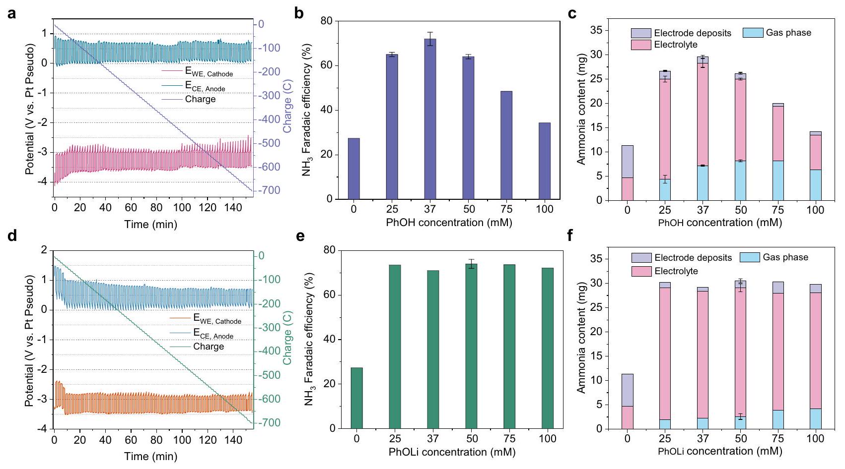
As found in our previous work, the optimal potential cycling condition entails applying a current density of for 1 min (the corresponding potential denoted deposition potential) and then for 1 min (the corresponding potential denoted resting potential) . The FEs of proton shuttles were obtained by passing a total charge of 700 C under the optimal potential cycling condition. As shown in Fig. 2a, the chronopotentiometry (CP) of PhOH exhibited average anode potential and cathode potential values of approximately 0.7 V and -3.6 V versus Pt , respectively. The FE towards ammonia was found to be dependent on the concentration of PhOH , with FE of at the optimal concentration of 37 mM (Fig. 2b). This concentration dependence arises from the presence of protons within PhOH , which directly influences the available proton concentration in the Li-NRR system (Supplementary Fig. 5). In comparison to the absence of a proton shuttle, the ammonia produced using PhOH was predominantly distributed in the gas phase
and electrolyte, accounting for over of the total ammonia generated (Fig. 2c). During the 1 min resting period at the open-circuit voltage (OCV), the resting potential of the cathode in the CP curve is expected to increase because of the reaction between the proton shuttle and the cathode surface species. The resting potential in the absence of the proton shuttle was -3 V versus Pt , which can be the benchmark for the resting potential in the presence of the proton shuttle (Supplementary Fig. 6). For example, the resting potential with ethanol is -2 V versus Pt , but with acetate acid, it is -1 V versus Pt due to its highly acidic nature (Supplementary Figs. 7 and 8). When comparing compounds 2 and 6,5 and 7,18 and 19 , as well as 12 and 13 , a higher ratio of ammonia in electrode deposits to a total ammonia (i.e., the proton shuttle cannot protonate in time and the is accumulated) is observed when proton shuttles are substituted by larger groups (Supplementary Fig. 9). This higher ratio could be indicative of a lower protonation ability of the proton shuttle, which is reflected by the resting potential approaching -3 V (i.e., no oscillation) during OCV (Supplementary Figs. 6-8).
To provide further evidence of the proton shuttle’s ability to transfer protons in the actual Li-NRR process, we propose a procedure that involves utilizing the deprotonated form ( ) of the proton shuttle to evaluate its proton transfer capability. Additionally, when the most effective proton shuttle was identified, we suggest employing operando isotope-labeled mass spectrometry (i.e., deuterium oxidation reaction) to confirm that the hydrogen present in the produced ammonia originates from the HOR. Firstly, PhOH was substituted with lithium phenoxide (PhOLi) to evaluate its performance in the Li-NRR process. Figure 2d illustrates the CP of PhOLi, exhibiting that its anode and cathode potentials are consistent with those shown in Fig. 2a. During the initial ten minutes of CP (Fig. 2d), the anode and cathode potentials were shifted, which can be attributed to the relatively low
Fig. 2 | Performance of Li-mediated ammonia synthesis using phenol or lithium phenoxide as proton shuttles. a The chronopotentiometry using phenol as proton shuttles ( 37 mM ). b Faradaic efficiency changed with varying phenol concentrations. c The various phenol concentrations affect the distribution of produced ammonia in the electrolyte, gas phase, and electrode deposits. The chronopotentiometry using lithium phenoxide as proton shuttles ( 37 mM ).
e Faradaic efficiency changed with varying lithium phenoxide concentrations. The
various lithium phenoxide concentrations affect the distribution of produced ammonia in the electrolyte, gas phase, and electrode deposits. All potentials are without iR correction. The potential cycling condition is for 1 min and for 1 min . All experiments passed a total charge of 700 C at the current density of with the same potential cycling condition. Error bars represent the mean standard deviation derived from three independent measurements.
proton concentration in the early stages. It has been proved that the gas flow composition and electrolyte composition can affect the potential stability of the Pt pseudo reference electrode . A similar phenomenon was observed using lithium ethoxide (EtOLi) in the LiNRR process (Supplementary Fig. 10). Unlike PhOH, the ammonia FE was independent of the concentration of PhOLi (Fig. 2e), which indicated the available proton concentration in the electrolyte was only limited by the current density of HOR. Remarkably, a FE of was achieved at a PhOLi concentration of 50 mM , which closely approached the performance achieved at the optimal concentration of PhOH . These results serve as direct evidence that the deprotonated form of ions functions as the proton shuttle for proton transfer in the real Li-NRR process. When utilizing PhOLi, the distribution of ammonia in the gas phase is lower compared to using PhOH (Fig. 2f), which could be attributed to the different properties of the solid-electrolyte interphase (SEI) layer or electrode deposits.
To reveal the difference in SEI and electrode deposits between the PhOH and PhOLi (Supplementary Figs. 11 and 12), flow cell experiments were performed in an Ar -filled glovebox under four conditions – i.e., after a linear sweep voltammetry (LSV) test with either PhOH or PhOLi and after 700 C of CP with either PhOH or PhOLi. The scanning electron microscope (SEM), x-ray diffraction (XRD), and x-ray photoelectron spectrometer (XPS) transfer systems were utilized to avoid exposure to air and moisture (Supplementary Figs. 13-15). The SEM images reveal the formation of a dense SEI layer following the LSV test with PhOH, whereas fewer deposits were observed with PhOLi (Supplementary Fig. 16). After a total charge of 700 C in the CP test, the cathode surface of PhOLi exhibited an irregular and thicker layer of deposits, while a uniform and thinner layer of deposits was observed when using PhOH (Supplementary Figs. 17 and 18). In comparison to PhOH , the utilization of PhOLi as the proton shuttle exhibited a higher
mass density of cathode deposits and thicker electrode deposits (Supplementary Figs. 19-21). These differences could be contributing factors to the reduced presence of ammonia in the gas phase when PhOLi was employed as the proton shuttle (Fig. 2f). The XRD patterns confirmed the main component of electrode deposits is lithium fluoride (LiF) after 700 C of the CP test with PhOH or PhOLi (Supplementary Figs. 22 and 23). The depth-profiling XPS spectra further validated that LiF was the dominant species present in both the SEI and electrode deposits when using either PhOH or PhOLi, aligning with previous findings (Supplementary Figs. 24-29) . After 700 C of the CP test with PhOH or PhOLi, the N 1s peak at 398 eV is attributed to (Supplementary Figs. 28 and 29).
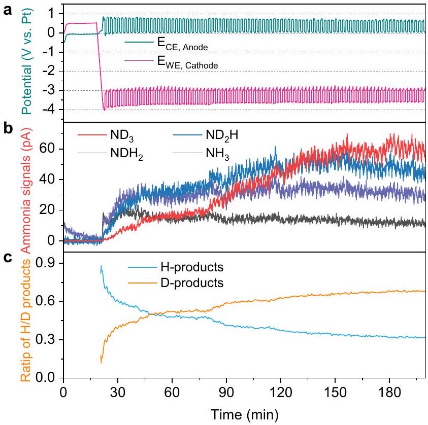
Operando isotope-labeled mass spectrometry is another necessary experiment for the proposed procedure to prove the ability to transfer the proton of the proton shuttle. The operando mass spectrometry was conducted in a continuous-flow reactor, wherein a deuterium ( ) oxidation reaction occurred at the anode side to generate protons ( ) to examine whether the proton shuttle ( PhOH ) can transfer the protons to the cathode products (Fig. 3). The products containing deuterium (D) and hydrogen (H) were measured at the cathode side using operando mass spectrometry (Supplementary Fig. 30). Initially, the cathode is surrounded by fresh electrolyte, resulting in a predominance of H -containing products such as and (Fig. 3b). As expected, as the experiment progresses, more and more the D-containing products were generated, eventually leading to a dominance of the fully deuterated ammonia ( ) (Fig. 3c). Those results unambiguously demonstrate the proton-shuttling capability of PhOH , transferring protons from HOR to the cathode products. At the initial stage, the PhOH is fully protonated with H , resulting in the generation of H -containing products. When the deprotonated form ( ) is formed, can be further re-protonated by
(Supplementary Fig. 31). Subsequently, the PhOD can protonate the lithium nitrides to generate the D-containing ammonia.
To further elucidate the ability of the deprotonated form ( ) to interact with protons during the Li-NRR process, nuclear magnetic resonance (NMR) spectra of electrolytes were conducted before and after the electrochemistry test (Supplementary Figs. 32 and 33). As shown in Fig. 4a, the deprotonated form ( ) acts as a proton acceptor, effectively protonating the protons originating from the HOR to form PhOH. Subsequently, the PhOH reacts with to release ammonia and regenerate the deprotonated form ( ). The
Fig. 3 | Operando mass spectrometry of cathodic ammonia gas products with isotope-labeled deuterium using phenol as proton shuttle. a The chronopotentiometry using phenol as proton shuttle. b Measured gas-phase ammonia when the anode occurs deuterium oxidation reaction. c The corresponding measured relative amounts of D -contained or H -contained ammonia.
NMR spectra of PhOLi and PhOH before the electrochemistry test are a benchmark for NMR analysis (Fig. 4b and Supplementary Fig. 34). The slight shift of NMR peaks of PhOH before and after the electrochemistry test (Supplementary Fig. 34) was due to slight differences in the pH (i.e., after test produced ammonia). Quantitative NMR measurements indicate that the amount of PhOH remains almost unchanged after the electrochemistry test (Supplementary Fig. 35). This suggests that PhOH is relatively stable under the experimental conditions and does not undergo significant decomposition or consumption during the Li-NRR process. Notably, after the electrochemistry test, almost all of the PhOLi were observed to convert into PhOH through protonation (Fig. 4c). This conversion of PhOLi to PhOH indicates the efficient proton transfer ability of PhOLi during the LiNRR process. Taken together, the set of experiments conducted, including the examination of the proton transfer capability of PhOLi in the real Li-NRR process, operando isotope-labeled mass spectrometry, and NMR analysis, provide unambiguous evidence of the protonshuttling capability of PhOH .
Deprotonated form of proton shuttle as proton buffer
Furthermore, when acetic acid was utilized as the proton shuttle, the FE of ammonia was only , primarily due to the enhanced occurrence of the competitive HER (Supplementary Fig. 36). When the mixture of PhOLi ( 37 mM ) with acetic acid was employed as the proton shuttle, the FE towards ammonia improved to (Supplementary Fig. 37). Upon the addition of an equivalent amount of PhOLi, only a minor portion of PhOLi underwent transformation into PhOH (Supplementary Fig. 38). Nevertheless, a significant reduction in the HER current was observed (Supplementary Fig. 36). These results indicated the proton-buffering capability of PhOLi. Therefore, the performance improvement (about FE) may be attributed to the proton-buffering capability of PhOLi (i.e., lowers the available proton concentration in the electrolyte), which effectively mitigates the adverse effects of the competitive HER (Supplementary Fig. 36).
Stability of deprotonated form for proton shuttle
One key requirement for an efficient proton shuttle is that the deprotonated form of the proton shuttle should demonstrate both
Fig. 4 | Demonstration of the ability of phenol for proton shuttling. a Schematic for proton-shuttling process of phenol in Li -mediated ammonia synthesis. The NMR spectra of lithium phenoxide in tetrahydrofuran before the electrochemistry
test. c The NMR spectra of post-reaction electrolytes using lithium phenoxide as proton shuttle after the electrochemistry test ( 700 C of CP ).
excellent electrochemical stability and chemical stability during the LiNRR process. We selected state-of-the-art EtOH as a reference for comparing stability. Figure 5a, b illustrate the deprotonation reactions of EtOH and PhOH , respectively. It is well known that the resonancestabilized phenoxide ion is more stable than an ethoxide ion , evidenced by the electrostatic potential maps from density functional theory (DFT) calculations (Fig. 5c, d), where less negative charge resides on the oxygen atom of phenoxide, compared to ethoxide. When lithium ethoxide (EtOLi) was used as a proton shuttle, the FE achieved was only (Supplementary Fig. 39), significantly lower than that of PhOLi ( ). The lower performance of EtOLi may be attributed to the relatively lower stability of the ethoxide ion compared to the phenoxide ion (Supplementary Figs. 35 and 40). The electrochemical stability of EtOH and PhOH was investigated in an aqueous electrolyte (Supplementary Fig. 41). The onset and peak oxidation potentials revealed a distinct stability order under the same experimental conditions: PhOH demonstrated superior stability compared to EtOH and THF, a result consistent with previous studies . Notably, the oxidation current density of PhOH was significantly smaller than that of EtOH, indicating excellent electrochemical stability. These findings emphasize the stability of PhOH as an efficient proton shuttle in the practical Li-NRR process.
Thermodynamic calculations indicate that, on the cathodic side, all electrochemical steps of NRR are energetically favorable under operation , while HOR is highly selective on the PtAu anode depending on whether ethanol or phenol is the shuttle
Fig. 5 | Stability of deprotonated form for proton shuttles. ab Deprotonated reaction of ethanol (a) and phenol (b). c, d Electrostatic potential map of ethoxide ion (c) and phenoxide ion (d).
(Supplementary Fig. 42). We, therefore, involve HOR as anodic reaction into a mass transport model, on the basis of our previous atomickinetic model , by a direct conversion between current density and proton flux from HOR (details see “Computational methods” section). We then employed a mass transport model to simulate the Li-NRR system based on the fact that diffusion of and is significantly slower than reaction kinetics and rate-limiting overall. The model, which is based on the model and extended to include homogeneous reactions in electrolytes , is described in detail in “Computational methods”, showing general consistency with experimental data (Supplementary Fig. 43, contributing to a reasonable understanding of the volcano-like relationship for proton shuttle concentrations vs. selectivity, and a prediction of shifted trend of optimal FE at the balance between vs. flux. The latter is dependent on proton shuttle concentrations and species. In the case of acidic shuttles with a lower , e.g., acetate acid, the proton is much easier to transport from anode to cathode by protonation and deprotonation, leading to a larger value of proton flux at the same concentration, thereby an increased FE of ammonia in the -limited region and a decreased FE in the -limited region, as shown in Fig. 6a. The deprotonated form ( ), unable to contribute to proton concentration in electrolytes, could retain the optimal performance when further increasing concentration (Supplementary Fig. 44), agreeing with experimental observation (Fig. 2e). At a specific proton shuttle concentration like our experimental setup, a new volcano plot (Supplementary Fig. 45) would be able to elucidate the effects of proton shuttle .
Accurate evaluation of in THF is essential to quantify proton shuttle influence. We applied solvent-corrected DFT to benchmark calculation (Supplementary Fig. 46) for a series of alcohols and acids. The calculation outcomes (Supplementary Table 2) show good agreement with the literature and expand the capacity of datasets in organic solvent . Taking the calculated into the mass transport model, we found that the single descriptor, , cannot completely explain proton shuttles’ influence on Li-NRR (Supplementary Fig. 47). As an example, an exception is phenol and 1-naphthol which have very close values (29.24 vs. 29.70), but significant difference in NRR FE performance ( vs. ). Considering the size difference between phenol and 1-naphthol, one may posit the size-related diffusivity of the proton shuttle, as the second descriptor for catalytic performance. At a specific value, a proton shuttle with low diffusivity would, at the same time, have slower proton diffusion, requiring compensation from increasing its concentration (Supplementary Fig. 48). The synergistic effects of and diffusivity on the resulting FE are graphically represented by Fig. 6b, in which an optimal would
Fig. 6 | Dependence of the Li-NRR performance on the and diffusion coefficient of proton shuttles. a A 1D plot of ammonia faradaic efficiency versus concentrations of proton shuttle with different . b Heatmap of the predicted
ammonia faradaic efficiency as a function of the of proton shuttle (x-axis) and diffusion coefficient (y-axis).
require either acidic but transport-limited proton shuttles or basic but transport-fast shuttles, in agreement with experimental discovery. The trade-off between diffusion and is a materialization of flux, still aligning with our original mass transport model .
In summary, proton shuttle screening has been performed in the practical Li-NRR process with HOR at the anode in a continuous-flow reactor. Proton shuttles play a crucial role in the transfer of protons from the HOR at the anode to the cathode for ammonia synthesis in the Li-NRR process. We propose a general procedure to validate the effectiveness of proton shuttles in the Li-NRR and establish design principles for developing efficient proton shuttles in practical Li-NRR processes. Through this procedure, we demonstrate that the PhOH exhibited excellent proton transfer capabilities and stability in the Li NRR process. Moreover, the PhOH exhibited an ammonia FE as high as , which is among the highest ammonia selectivity achieved in Li NRR at ambient conditions. The deprotonated form ( ) of the PhOH is proven to act as the primary species responsible for transferring protons during the Li-NRR process. The combination of theoretical calculations and micro-kinetic modeling provides an understanding of the mechanism of proton shuttling in the Li-NRR process. The findings contribute to the understanding of the mechanistic aspects and design principles for efficient proton shuttles in practical Li-NRR applications, ultimately paving the way for the development of sustainable and environmentally friendly ammonia production methods.
Synthesis procedures of phosphonium salts (Trihexyltetradecylphosphonium tris(pentafluoroethyl)trifluorophosphate, )
10.4 g of 1-ethyl-3-methylpyrrolidinium tris(pentafluoroethyl)trifluorophosphate ( ) and 11.1 g of trihexyltetradecylphosphonium chloride ( ) were added to a mixture of water ( ) and dichloromethane (DCM). The mixture was stirred vigorously for 1 h at room temperature. After the reaction, the organic DCM solution was washed with miliQ approximately 10 times until the silver chloride test showed no
reaction. After purification, DCM was removed in a vacuum at on a rotary evaporator. The residual water was removed by dissolving the resulting material in benzene and distilling it under a vacuum at . After purification, the resulting slightly yellowish compound was left drying in the oven at for at least overnight or over the weekend. The , and NMR showed a pure product and no starting material or contamination. The yield of the reaction was .
Material characterization
X-ray diffraction (XRD), X-ray Photoelectron Spectroscopy (XPS), and scanning electron microscope (SEM) were used to characterize electrodes and cathode electrode deposits. To analyze the solidelectrolyte interface (SEI, after LSV) or post-reaction electrodes (electrode deposits, after 700 C ), WE electrodes were characterized after electrochemistry with XRD, XPS, and SEM. The flow cell experiments were performed in an Ar-filled glovebox and a transfer system was used to minimize the exposure to air. For XRD, a gas-tight polycarbonate (PC) dome (Anton Paar) was used to cover the sample on top of the XRD sample holder during the transport from the glovebox to the instrument as well as during the measurement. For XPS, the samples were transported from the glovebox to the XPS via a vacuum transfer system. The SEM samples were transported from the glovebox to the SEM via a cryo-SEM transfer rod. XRD data were recorded with the Data Collector v5.4 software on a Malvern Pananalytical Empyrean X-ray diffractometer. On the incident beam path, a parallel beam X-ray mirror for Cu radiation was used with a fixed 10 mm mask and a slit placed 140 mm from the sample. The diffracted beam path was equipped with a parallel plate collimator having an opening of . The source was an Empyrean Cu LFF HR gun operated at 45 kV and 40 mA , with and a Ni beta-filter. The data were analyzed with HighScore Plus v4.6a by Panalytical with reference patterns from the Inorganic Crystal Structure Database (ICSD). X-ray Photoelectron Spectroscopy was performed using a ThermoScientific Thetaprobe instrument equipped with an Al K X-ray source with a chamber base pressure below . Survey spectra were recorded with 50 scans at 50 ms dwell time per 1 eV step. Elemental detail spectra were recorded with scans in 0.1 eV steps with 50 ms dwell time. The lateral resolution was and a value of pass energy of 100 or 200 eV was used. The chamber pressure was risen to by flowing 6.0 Ar gas as required using a flood gun, which was used in charge neutralization mode during the measurement. The data were acquired and analyzed using Thermo Advantage v5.9917 by Thermo Fischer Scientific. All data were fitted with the Powell fitting algorithm and the background was determined by the Smart background option, which is based on the Shirley background.
Preparation of cathode electrodes
The 316 stainless steel cloth (SSC, McMaster-Carr, mesh, pore size of ) was used as the cathode electrodes for the electrochemical ammonia synthesis test. Before use, the SSC was cleaned with acetone and ethanol 3 times. The treated SSC was dried in the vacuum oven for further use.
Preparation of anode electrodes
The PtAu/SSC was prepared by electrodeposition as previously described. Brief description for the electrodeposition, SSC with a pore size of (McMaster-Carr, ) was used as the working electrode, and two Pt mesh electrodes (Goodfellow, ) were electrically connected and used as a split counter electrode. The (Sigma-Aldrich, ACS reagent) with (Sigma-Aldrich, ) in (Sigma-Aldrich, ) solution was used as the electrolyte for electrodepositing PtAu/SSC. A current density of was applied for 2 min in which rigorous hydrogen evolution and metal
deposition took place at the same time, leading to high surface area structures of PtAu on the SSC. After the electrodeposition, the electrodes were rinsed in EtOH and ultra-pure water ( resistivity, Millipore, Synergy UV system) several times to remove residual electrolytes.
Electrochemical experiments
The electrochemical ammonia synthesis was performed in a threechamber flow cell (Supplementary Fig. 1). The effective electrode area of the flow cell was . The central electrolyte chamber is made of polyetheretherketone (PEEK, THF-resistant materials). The (5.0, Air Liquide) and (5.0, Air Liquide) gas flow rates were controlled using a mass flow controller (Brooks Instrument) and set to 75 sccm . The and used in the experiments were cleaned by purifiers (NuPure) to reduce labile N-containing compounds to parts per trillion by volume (ppt-v) level. Before each experiment, the flow cell parts were boiled in ultra-pure water for 3 h and dried overnight at in an oven. The cleaned SSC ( mesh, thickness: ) was used as the working electrode (WE, cathode). As-prepared PtAu/SSC was used as the counter electrode (CE, anode). The pseudo reference electrode (RE) was a Pt wire (Goodfellow, 99.99%, diameter: 0.5 mm ). Before electrochemical tests, the Pt wire was flame-annealed.
The (Sigma-Aldrich, , anhydrous) was dried at for 48 h in a vacuum oven before use. Ethanol (Honeywell, anhydrous) was dried with molecular sieves. Electrolyte solution consisted of in tetrahydrofuran (THF, anhydrous, , inhibitor-free, Sigma-Aldrich) and proton shuttles and was prepared in an argon-filled glovebox. A syringe pump (World Instruments) was used to control the flow rate of the electrolytes at . The syringe (Trajan Scientific and Medical, 100 ml ) consisted of a borosilicate glass tube and a PTFE plunger (Gas tight). 1 mM of HCl (Sigma-Aldrich, Suprapur) aqueous solution was used to control the back pressure and trap the gas-phase ammonia. The gas outlet back pressure of the flow cell was modulated by a 10.5 centimeters 1 mM of HCl solution column , which leads to a pressure gradient of 15 mbar between the gas inlet and outlet of the flow cell. Before the injection of electrolyte into the electrolyte chamber, the purified and were introduced into the empty assembled flow cell for at least 30 min . Afterward, the electrolyte solution was injected into the cell in and atmospheres.
The electrochemistry experiments were conducted using a BioLogic Potentiostat (VMP2). The resistance between the WE and RE was measured using the potentiostatic electrochemical impedance spectroscopy (PEIS) and the current interrupt technique. The linear sweep voltammetry (LSV) was recorded from the open-circuit voltage (OCV) until lithium plating is clearly seen. Subsequently, chronopotentiometry (CP) was measured with potential cycling. The potential cycling refers to that (the corresponding potential denoted deposition potential) was applied for 1 min and then (the corresponding potential denoted resting potential) for 1 min .700 C of charge was passed for each experiment to determine the ammonia Faradaic efficiency (FE). We note that all experiments were conducted at room temperature and 1 bar pressure. Typically, flow cell experiments were performed in a fume hood. For analysis of the electrode deposits on the working electrode, the flow cell was run in an Ar-filled glovebox. As the phosphonium salts are sensitive to the water content, using phosphonium salts as proton shuttle experiments were run in an Ar-filled glovebox. The water content of the electrolyte was measured by Karl Fischer Titration ( 831 KF Coulometer and 728 Stirrer, Metrohm). Before the electrochemistry test, the water content in the electrolyte with phosphonium salts is about . When the experiment finished, total production was quantified from the (1) gas-phase trapped in 1 mM of HCl , (2) trapped in the electrolyte, and (3) trapped in the electrode deposits. Typically, of ultra-pure water was used to dissolve the electrode
deposits to release trapped . We note that can react with N -containing compounds (e.g., ) in the electrode deposits to produce .
THF, EtOH, and PhOH oxidation experiments in aqueous electrolyte
A good proton shuttle should have high electrochemical stability during the Li-RR process. To evaluate the electrochemical stability of THF, EtOH, and PhOH on the PtAu anode catalysts, the oxidation experiments in an aqueous electrolyte were carried out in a custommade three-electrode glass cell using the rotating disk electrode method. The reference electrode was calibrated before the electrochemistry test. A Pt wire was used as a counter electrode. The working electrode ( ) was obtained from electrodeposited PtAu on a titanium stub ( ). To prepare the PtAu/Ti electrode, an electrolyte of (Sigma-Aldrich, ACS reagent) with (Sigma-Aldrich, ) in (Sigma-Aldrich, 99.999%) was used. A current density of was applied for 2 min in which rigorous hydrogen evolution and metal deposition took place at the same time with 2500 revolutions per minute. The cyclic voltammetry (CV) curve was recorded between 0 and 1.2 V vs RHE at in Ar-saturated . The THF, EtOH , and PhOH oxidation activity was evaluated in Ar -saturated 0.1 M with 0.1 M THF or 0.1 M EtOH or 0.1 M PhOH electrolyte with a scan rate of .
oxidation experiment via online mass spectrometry
Mass spectrometry (MS) measurements were collected with a QMG 422, using a 100 mm long QMA 120 quadrupole mass filter (QMS) from Balzers. The QMS was optimized for soft ionization measurements at 26 eV ionization energy, ensuring minimum cracking patterns in the mass spectra, while allowing for a decent signal. The experimental setup is schematically shown in Supplementary Fig. 30. The MS is placed downstream on the flow from the cathode side of the flow cell. This allows for operando measurements of the flow cell operation and performance. The connecting gas line is heat traced to , to avoid sticking ammonia to the inner tube walls and increase collection efficiency and time resolution. The continuous gas collection is through a flow calibrated orifice from Lenox Laser. Measurements with electrolytes in the flow cell are collected under a low vacuum of typically , while the vacuum chamber is heated to . The vacuum is sustained by a HiPace 300 H Turbo Pump from Pfeiffer Vacuum. The electrochemical reaction was performed in the flow cell electrolyzer. The electrolyte consisted of in THF with 37 mM phenol. The electrochemical test is similar to the previous section. Deuterium ( atom % purity) and nitrogen ( , 5 N purity) flow rates were controlled with mass flow controllers (Brooks), and both were set to . The liquid electrolyte was continuously flown at ambient pressure at , controlled by a peristaltic pump with PTFE-lined tubing (ZHUNZE, BF400H). Gas pressure was modulated by passing outlet gas through a 10.5 cm acidified water column. outlet gas was passed directly through a water column, whereas the gas outlet was flowed by the mass spectrometer before passing through a water column. Once both gasses and electrolytes were flowing, the mass spectrometer was started and measured on the gas outlet. The baseline mass signals were measured during OCV, after which the potential cycling procedure was started, switching between 1 min deposition at and 1 min resting at .
Quantification of ammonia
Ammonia production was quantified using ion chromatography (IC, Metrohm) with an autosampler. The materials of the connection tubes, pressure screws, capillaries, and injection needles were PEEK or PTFE (THF-resistant materials). The IC could
measure THF-containing samples that were diluted with ultra-pure water. The IC detection system is a conductivity detector. The cation column (Metrosep C6) was used as a high-capacity separation column. The Metrosep C6 column material was silica gel with carboxyl groups. The eluent (mobile phase) was (Sigma-Aldrich, Suprapur) solution with 10 vol. acetone (Sigma-Aldrich, ). The eluent flow rate was . Before use, the eluent was degassed for 30 min to prevent gas bubbles in the high-pressure pump. For the IC measurements, a volume of the sample was injected and measured for 20 min . As THF-containing electrolytes could damage the IC and a high concentration of calcium ions could cause adsorption saturation of the column, the electrolyte was diluted times with ultra-pure water. The dilution factor depends on the specific experiment and the expected amount of ammonia produced. To protect the cation column, if the sample or diluted sample contains visible particles, it was pretreated by a filter syringe with a PTFE filter membrane (Whatman Puradisc, ) to remove the particles before testing IC. Based on the IC settings and conditions, the retention time for the standard cation solution (Sigma-Aldrich) was: 6.48 min for for , and 15.32 min for . The retention time of was 10.60 min . Ammonium chloride (Sigma-Aldrich, 99.998%) solution was used to make the calibration curve. The reliability of the IC method was verified by the colorimetric indophenol method, previously described .
Nuclear magnetic resonance (NMR) Analysis
The NMR characterization of the samples was performed at using a Bruker AVANCE III HD spectrometer operating at frequency of 800 MHz equipped with a 5 mm TCI CryoProbe (Bruker Biospin). The samples contained THF with 2 signals in the spectra at approximately 2 and 4 ppm which were reduced to extract the signals of interest. The spectra also contained 2 signals of ethanol at approximately 1.5 and 4 ppm, however, the proton on the oxygen is drifting and might not be seen in general in the spectrum. The chemical shifts were normalized to tetramethylsilane (TMS). In general, some variation in the chemical shift of the NMR signals could appear due to some differences in the pH , volume, and/or temperature of the sample. The data were analyzed with Bruker Topspin 4.1.4 with an academic license. 37 mM of phenol in THF and 50 mM of lithium phenoxide in THF were tested as a reference. For the phosphonium salt ( ), the and NMR were recorded. For quantitative analysis, the signal of acetone ( 270 mM ) which was used as a calibration compound was integrated and normalized according to the number of protons giving rise to the signal. In all spectra, there was only one signal of acetone at meaning that no enol tautomer was present. The concentration of a compound of interest ( x ) in the presence of acetone as a calibrant was calculated according to the formula where I, N , and C are the integrated area, number of nuclei, and concentration of the compound of interest ( x ) and the calibrant ( cal ), respectively. It is important to mention that the assumption is the acetone is totally pure.
Faradaic efficiency calculations
To calculate the Faradaic efficiency (FE), the concentrations of synthesized ammonia in the electrolyte ( ), gas-phase trapped solution , and electrode deposits dissolved solution were measured via ion chromatography, along with the volume, , and , respectively, after each measurement. This is compared with the total charged passed, Q (unless otherwise specified, it is 700 C ):
where F is Faraday’s constant, and 3 is the number of electrons transferred during the reaction for each mole of .
Determination of the ammonia content in electrolyte deposits
After the electrochemical test, the cathode electrode (containing the electrolyte deposits) was immersed in ultra-pure water ( ) and ultrasonicated for 2 min . The electrode deposit dissolved solution was pretreated by a filter syringe with a PTFE filter membrane (Whatman Puradisc, ) to remove the particles. After that, the filtered solution was measured via ion chromatography (IC). Based on this, the released ammonia of the electrode deposit was determined. It should be noted that can react with N -containing compounds (e.g., ) in the electrode deposits to release . With effective proton shuttles in the electrolyte, the produced from electrode deposits should be in a small amount. The amount of ammonia released from the electrode deposits can be used as an indicator of the protonation ability of the proton shuttle. In other words, the more ammonia released from the electrode deposits, which means the lower the protonation ability of the proton shuttles.
Computational methods
Reaction energies calculations. Density functional theory (DFT) calculations were employed to calculate reaction energies for HOR and ethanol, phenol oxidation on PtAu catalysts, with the Vienna Ab Initio Simulation Package (VASP) . Based on our previous work, here we took aggregate , and facets into consideration. Ethanol oxidation was simulated in a pathway of , while phenol oxidation along . In all calculations, the exchange-correlation energy was modeled by using Perdew-BurkeErnzerhof (PBE) functional within the generalized gradient approximation (GGA) . The projector-augmented wave (PAW) pseudopotentials were used to describe ionic cores . The cutoff energy of 750 eV was adopted for all adsorption calculations. A MethfesselPaxton smearing of 0.05 eV to the orbital occupation was applied during the geometry optimization and for the total energy computations. In all calculations, the atoms at all positions have Hellmann-Feynman forces lower than and the electronic iterations convergence was using the Normal algorithm. All configurations can be found in the public GitHub repository: https:// github.com/onealshu/phenol.git. During the adsorption calculations, the bottom two layers are fixed at the tested lattice positions while other layers including adsorbates are fully relaxed. Reaction energies were calculated based on the computational hydrogen electrode model .
The calculations. The for a molecule was calculated from the solution phase free energy of the deprotonation reaction,
where . Free energies were obtained by considering electronic energies and frequency corrections, in the sum of electronic and thermal free energies from Gaussian . Atomic models are established in explicit THF molecules, after benchmarking the number of THF (Supplementary Fig. 46). During calculations, all atoms are flexible in three directions and considered to compute frequency. Relaxations and frequency calculations were performed with functional of B3LYP , basis set, at and . For ions like proton or , extra positive/negative charge was set in the explicit model. All configurations can be found in the same GitHub repository.
Mass transport simulations. A 1-D full mass transport limiting model was developed to simulate the Li-NRR system. Nernst-Planck equation was employed to simulate the diffusion and migration of species in the model, with average conductivities for the SEI layer and boundary layer (liquid electrolyte).
Planck equation with a boundary thickness of .
where is the concentration, is the diffusion coefficient, is the charge of species is the potential of the electrolyte, is the time, is the ideal gas constant and is the temperature, is the Faraday constant.
To solve these equations, we set up the Neumann boundary conditions for and , while Dirichlet boundary conditions for and to simulate the full mass transport limiting condition at the electrode side: (electrode surface):
To simulate the influence of anodic reaction, we involve HOR in the model by setting a constant boundary condition for proton flux, , at the end of the boundary layer,
is Faraday constant.
Protonation and deprotonation reactions of proton shuttle like ethanol or phenol were considered in the boundary layer,
All parameters and set up in the model can be found in the same GitHub repository.
Data availability
All data reported in the main text and Supplementary Information are available from the corresponding author upon reasonable request.
References
Iriawan, H. et al. Methods for nitrogen activation by reduction and oxidation. Nat. Rev. Method Prime 1, 56 (2021).
Chen, J. G. et al. Beyond fossil fuel-driven nitrogen transformations. Science 360, eaar6611 (2018).
Fu, X. B., Zhang, J. H. & Kang, Y. J. Recent advances and challenges of electrochemical ammonia synthesis. Chem. Catal. 2, 2590-2613 (2022).
Li, K. et al. Enhancement of lithium-mediated ammonia synthesis by addition of oxygen. Science 374, 1593-1597 (2021).
Suryanto, B. H. R. et al. Challenges and prospects in the catalysis of electroreduction of nitrogen to ammonia. Nat. Catal. 2, 290-296 (2019).
Qing, G. et al. Recent advances and challenges of electrocatalytic reduction to ammonia. Chem. Rev. 120, 5437-5516 (2020).
Westhead, O. et al. Near ambient fixation on solid electrodes versus enzymes and homogeneous catalysts. Nat. Rev. Chem. 7, 184-201 (2023).
Singh, A. R. et al. Electrochemical ammonia synthesis-the selectivity challenge. ACS Catal. 7, 706-709 (2017).
Andersen, S.Z. et al. A rigorous electrochemical ammonia synthesis protocol with quantitative isotope measurements. Nature 570, 504-508 (2019).
Choi, J. et al. Identification and elimination of false positives in electrochemical nitrogen reduction studies. Nat. Commun. 11, 5546 (2020).
Fichter, F. Elektrolytische Bindung von komprimiertem Stickstoff bei gewöhnlicher Temperatur. Helv. Chim. Acta 13, 1228-1236 (1930).
Tsuneto, A. et al. Efficient electrochemical reduction of to catalyzed by lithium. Chem. Lett., 5, 851-854 (1993).
Andersen, S. Z. et al. Increasing stability, efficiency, and fundamental understanding of lithium-mediated electrochemical nitrogen reduction. Energy. Environ. Sci. 13, 4291-4300 (2020).
Lazouski, N. et al. Non-aqueous gas diffusion electrodes for rapid ammonia synthesis from nitrogen and water-splitting-derived hydrogen. Nat. Catal. 3, 463-469 (2020).
Cai, X. Y. et al. Lithium-mediated electrochemical nitrogen reduction: mechanistic insights to enhance performance. iScience 24, 103105 (2021).
Suryanto, B. H. R. et al. Nitrogen reduction to ammonia at high efficiency and rates based on a phosphonium proton shuttle. Science 372, 1187-1191 (2021).
Li, K. et al. Increasing current density of li-mediated ammonia synthesis with high surface area copper electrodes. ACS Energy Lett. 7, 36-41 (2022).
Cai, X. Y. et al. Membrane electrode assembly design for lithiummediated electrochemical nitrogen reduction. Energy. Environ. Sci., 16, 3063-3073 (2023).
Sazinas, R. et al. Oxygen-enhanced chemical stability of lithiummediated electrochemical ammonia synthesis. J. Phys. Chem. Lett. 13, 4605-4611 (2022).
Krishnamurthy, D. et al. Closed-loop electrolyte design for lithiummediated ammonia synthesis. ACS Cent. Sci. 7, 2073-2082 (2021).
Lazouski, N. et al. Proton donors induce a differential transport effect for selectivity toward ammonia in lithium-mediated nitrogen reduction. ACS Catal. 12, 5197-5208 (2022).
Du, H. L. et al. The chemistry of proton carriers in high-performance lithium-mediated ammonia electrosynthesis. Energy. Environ. Sci. 16, 1082-1090 (2023).
Steinberg, K. et al. Imaging of nitrogen fixation at lithium solid electrolyte interphases via cryo-electron microscopy. Nat. Energy 8, 138-148 (2023).
Gao, L. F. et al. Domino effect: gold electrocatalyzing lithium reduction to accelerate nitrogen fixation. Angew. Chem. Int. Ed. 60, 5257-5261 (2021).
Du, H. L. et al. Electroreduction of nitrogen with almost current-to-ammonia efficiency. Nature 609, 722-727 (2022).
Li, S. et al. Electrosynthesis of ammonia with high selectivity and high rates via engineering of the solid-electrolyte interphase. Joule 6, 2083-2101 (2022).
Fu, X. et al. Continuous-flow electrosynthesis of ammonia by nitrogen reduction and hydrogen oxidation. Science 379, 707-712 (2023).
Krempl, K. et al. Electrolyte acidification from anode reactions during lithium mediated ammonia synthesis. Electrochem. Commun. 134, 107186 (2022).
Schwalbe, J. A. et al. A combined theory-experiment analysis of the surface species in lithium-mediated electrosynthesis. ChemElectroChem 7, 1542-1549 (2020).
McShane, E. J. et al. A versatile reference electrode for nonaqueous electrochemical conversion technologies. ACS Energy Lett. 8, 230-235 (2023).
Tort, R. et al. Nonaqueous Li-mediated nitrogen reduction: taking control of potentials. ACS Energy Lett. 8, 1003-1009 (2023).
Went, C. in Ionic Organic Mechanisms (ed. Thompson, J.) 58-78 (Palgrave, 1986).
McMurry, J. E. in Fundamentals of Organic Chemistry (ed. Lockwood, L.) 261-262 (Cengage Learning, 2010).
Avgousti, C. et al. The electrochemical oxidation of tetrahydrofuran in sulphuric acid solution. Electrochim. Acta 44, 3295-3301 (1999).
Zhang, L. Y. et al. Ultrasmall and uniform clusters strongly suppress Ostwald ripening for efficient ethanol oxidation. Electrochem. Commun. 84, 1-5 (2017).
de Souza, R. B. A. & Ruotolo, L. A. M. Phenol electrooxidation in different supporting electrolytes using boron-doped diamond anodes. Int. J. Electrochem. Sci. 8, 643-657 (2013).
Kutt, A. et al. values in organic chemistry – making maximum use of the available data. Tetrahedron Lett. 59, 3738-3748 (2018).
Kresse, G. & Hafner, J. Ab initio molecular dynamics for liquid metals. Phys. Rev. B Condens. Matter. 47, 558-561 (1993).
Kresse, G. & Furthmuller, J. Efficiency of ab-initio total energy calculations for metals and semiconductors using a plane-wave basis set. Comput. Mater. Sci. 6, 15-50 (1996).
Perdew, J. P. et al. Generalized gradient approximation made simple. Phys. Rev. Lett. 77, 3865-3868 (1996).
Kresse, G. & Joubert, D. From ultrasoft pseudopotentials to the projector augmented-wave method. Phys. Rev. B 59, 1758-1775 (1999).
Norskov, J. K. et al. Origin of the overpotential for oxygen reduction at a fuel-cell cathode. J. Phys. Chem. B 108, 17886-17892 (2004).
Frisch, M. E. et al. Gaussian 16 (Gaussian, Inc., 2016).
Stephens, P. J. et al. Ab-initio calculation of vibrational absorption and circular-dichroism spectra using density-functional forcefields. J. Phys. Chem. 98, 11623-11627 (1994).
Acknowledgements
I.C. gratefully acknowledges the funding by Villum Fonden, part of the Villum Center for the Science of Sustainable Fuels and Chemicals (VSUSTAIN grant 9455), Innovationsfonden (E-ammonia grant 9067O0010B), and the European Research Council (ERC) CLUNATRA under the European Uanion’s Horizon 2020 research and innovation program (grant agreement no. 741860). X.F. was supported under the MSCA European Postdoctoral Fellowships (Electro-Ammonia Project 101059643).
Author contributions
Conceptualization of the work was by X.F., A.X., J.K.N. and I.C. Data curation was by X.F., A.X., J.B.P., S.L., R.S. and M.S. Formal analysis was carried out by X.F., A.X., J.B.P. and S.L. Investigation was by X.F., A.X., S.L. and M.S. Equipment design was by X.F., M.S., J.B.P. and S.Z.A. Visualization was by X.F. and A.X. The project was supervised by J.K., P.C.K.V., J.K.N. and I.C. The original draft was written by X.F. and A.X., and the manuscript was reviewed and edited by X.F., A.X., S.L., Y.Z., N.H.D., J.B.V.M., J.K., P.C.K.V., J.K.N. and I.C.
Competing interests
The Authors declare the following competing interests. A patent application titled “Flow cell for electrochemical ammonia synthesis” was submitted on 09-09-2022 (application number: EP22194879) regarding the reported phenol as proton shuttles in the paper. Inventors: M.S., J.B.P., X.F., S.Z.A., R.S., S.L., Y.Z., K.L., J.K., P.C.K.V., J.K.N., I.C. J.B.V.M, N.H.D. Institution: DTU. M.S. and S.Z.A. declare the following competing interests: they have equity ownership in NitroVolt ApS, a Danish company working on commercializing electrochemical ammonia synthesis. The other authors declare no competing interests.
Additional information
Supplementary information The online version contains
supplementary material available at https://doi.org/10.1038/s41467-024-46803-w.
Correspondence and requests for materials should be addressed to Jens K. Nørskov or lb Chorkendorff.
Peer review information Nature Communications thanks the anonymous, reviewers for their contribution to the peer review of this work. A peer review file is available.
Publisher’s note Springer Nature remains neutral with regard to jurisdictional claims in published maps and institutional affiliations.
Open Access This article is licensed under a Creative Commons Attribution 4.0 International License, which permits use, sharing, adaptation, distribution and reproduction in any medium or format, as long as you give appropriate credit to the original author(s) and the source, provide a link to the Creative Commons licence, and indicate if changes were made. The images or other third party material in this article are included in the article’s Creative Commons licence, unless indicated otherwise in a credit line to the material. If material is not included in the article’s Creative Commons licence and your intended use is not permitted by statutory regulation or exceeds the permitted use, you will need to obtain permission directly from the copyright holder. To view a copy of this licence, visit http://creativecommons.org/ licenses/by/4.0/.
(c) The Author(s) 2024
Department of Physics, Technical University of Denmark, Kongens Lyngby, Denmark. These authors contributed equally: Xianbiao Fu, Aoni Xu. – e-mail: jkno@dtu.dk; ibchork@fysik.dtu.dk