الكيمياء الكهربائية الهرمية لليثيوم باستخدام أنود من نوع السبيكة لبطاريات الليثيوم المعدنية ذات الكثافة الطاقية العالية Hierarchical Li electrochemistry using alloy-type anode for high-energy-density Li metal batteries
استغلال أنود الليثيوم المعدني الرقيق ضروري لبطارية ذات كثافة طاقة عالية، ولكنه يعاني بشدة من ضعف قابلية معالجة الليثيوم، بالإضافة إلى سلوكيات الطلاء/الإزالة غير القابلة للتحكم لليثيوم.واجهة الإلكتروليت. هنا، نوع رقيق قابل للتعديل في السماكة/السعة من السبائكتم تصنيع الأنود لبطاريات الليثيوم المعدنية ذات الكثافة الطاقية العالية. السبائك الليثوفيلية LiZn التي تم تشكيلها فييمكن أن ينظم الأنود بشكل فعال ترسيب/إزالة الليثيوم ويستقر واجهة الليثيوم/الإلكتروليت لتقديم كيمياء كهربائية هرمية لليثيوم. عند الشحن،يعمل الأنود أولاً كمصدر لليثيوم لاستخراج ليثيوم متجانس. في نهاية الشحن، يساهم تفكيك هياكل ليثيوم-زنك النانوية بشكل إضافي في استخراج الليثيوم، حيث يلعب فعليًا دور تعويض الليثيوم في دورة البطارية. بينما عند التفريغ، يتشكل سبيكة ليثيوم-زنك في البداية، مما ينظم الترسيب المتجانس لليثيوم التالي. إن قابلية عكسية هذه العملية المثيرة للاهتمام تم التحقق منها بلا شك من خلال الكيمياء الكهربائية وخصائص XRD في الموقع. تسلط هذه الدراسة الضوء على التصنيع السهل للأنودات المعدنية لليثيوم العملية ومواد تعويض الليثيوم المفيدة لبطاريات ليثيوم المعدنية ذات الكثافة العالية للطاقة.
منذ أول تجاري لها في التسعينيات، تتمتع بطاريات الليثيوم أيون (LIBs) بسلامة عالية بفضل آلية الاستخراج/الإدخال، قد أثبتت الدور السائد في سوق تخزين الطاقة لأكثر من 30 عامًاومع ذلك، على الرغم من أن تحسينات كبيرة قد تم تطبيقها، لا يزال هناك فجوة كبيرة بين كثافة الطاقة لبطاريات الليثيوم أيون من نوع “كرسي الهزاز” ومتطلبات الصناعات الناشئة.فيما يتعلق بالاختيار النهائي لنظام جديد عالي الكثافة للطاقة، فإن الليثيوم المعدني (Li) يتميز بسعته العالية (10 مرات أعلى من أنود الجرافيت)، وأدنى جهد اختزال (-3.04 فولت مقابل SHE)، وكثافة كتلة خفيفة.. بينما تتضمن كيمياء بطارية الليثيوم عمليات الطلاء والتقشير المتكررة لليثيوم، حيث سيؤدي الأنود المعدني لليثيوم (LMA) حتمًا إلى تحفيز ترسبات شبيهة بالشجرة وتغيرات حجم غير قابلة للتحكم بسبب الركيزة غير المثالية وطبيعتها “بدون إطار”، مما يعيق تقدمها الإضافي من المختبر إلى التسويقحتى الآن، تم اقتراح عدة استراتيجيات فعالة لتطوير مركبات LMA أو LMAb المستندة إلى التطبيقات العملية لبطاريات الليثيوم أيون ذات الكثافة الطاقية العالية. على سبيل المثال، يعد تغليف الليثيوم المعدني داخل حوامل ثلاثية الأبعاد (3D) ذات مساحة سطح محددة عالية وفتحات كافية وسيلة قابلة للتطبيق لتعزيز قابلية إعادة طلاء/إزالة الليثيوم واستقرار الحجم.علاوة على ذلك، يمكن أن يؤدي التصميم العقلاني لتكوين الإلكتروليت (مثل أملاح الليثيوم عالية التركيز والإضافات الجديدة) أو إدخال واجهة الإلكتروليت الصلبة الاصطناعية (SEI) إلى تحسين متانة واجهة الليثيوم/الإلكتروليت كاستراتيجية غير مباشرة للحد من نمو LMA ونمو دندريتات الليثيوم.. ومع ذلك، فإن معظم تعديلات LMAs تعتمد على رقائق الليثيوم السميكة (، مما يتوافق مع سعة سطحية من ) أو مضيفين ثلاثي الأبعاد سميكين على الرغم من الأداء الأفضل في الدراجات الذي حققوه، إلا أن LMAs الزائدة عن الحاجة لا يمكن أن تتناسب بشكل معقول مع سعة الكاثودات التجارية الحالية (على سبيل المثال.
في نسبة منخفضة من النيتروجين إلى الفوسفور (<3)، مما يؤدي إلى هدر معظم مصادر الليثيوم مع التأثير على كثافة الطاقة. علاوة على ذلك، فإن LMAs المعدلة السميكة، كمصادر غير محدودة من الليثيوم، لا يمكن أن تعكس فعالية استراتيجيات التحسين في الواقع بسبب التجديد المستمر لفقدان الليثيوم أثناء الدورة. لذلك، فإن كيفية تصنيع LMAs الرقيقة (على سبيل المثال، ) لمطابقة الكاثودات التجارية بشكل أفضل مع نسب N/P المناسبة بشكل عام، يتم تصنيع رقائق الليثيوم (من 50 إلى مئات الميكرونات) عن طريق الدرفلة الميكانيكية في الصناعة، ولكن هناك بعض المشاكل المتأصلة في الليثيوم المعدني عندما يتحمل التشوه الميكانيكي. حيث أن التأثير القوي للزحف الناتج عن الانتشار بسبب درجة الحرارة المتماثلة العالية، يصبح الليثيوم المعدني لزجًا للغاية وذو قابلية معالجة ميكانيكية ضعيفة، مما يشكل تحديًا كبيرًا في إنتاج المواد المعدنية الخفيفة الرقيقة.. بالإضافة إلى ذلك، من السهل توليد خدوش ميكانيكية على سطح الليثيوم الناعم أثناء عملية الدرفلة، مما يؤدي إلى الأيونات تميل إلى الترسب عند هذه البروزات غير المتساوية. وبالتالي، عند تحضير أنود الليثيوم بسمك أقل منستزداد متطلبات دقة آلة الدرفلة وتكلفة التحضير وصعوبته بشكل حاد.
في الواقع، إعادة معالجة معدن الليثيوم في حالته السائلة هي اتجاه واعد لتحضير أنودات مركبة من الليثيوم، مثل حقن الليثيوم المنصهر في حوامل ثلاثية الأبعاد لإعادة تشكيل مورفولوجيا الليثيوم.في هذه المرحلة، يرتبط سمك الأنود المركب من الليثيوم ارتباطًا وثيقًا بسمك المضيف ثلاثي الأبعاد. من خلال التحكم في سماكات المضيفات ثلاثية الأبعاد، يمكن الحصول على أنابيب الكربون النانوية الرقيقة.وأكسيد الجرافين المخفضيمكن تحضير مصادر الليثيوم المحدودة بسهولةومع ذلك، فإن التحضير للمضيفات ثلاثية الأبعاد الرقيقة معقد ومرتفع التكلفة. طريقة أخرى قابلة للتطبيق وفعالة من حيث التكلفة هي إعادة تشكيل سمك الليثيوم في الحالة السائلة مباشرة. للأسف، فإن التوتر السطحي العالي لليثيوم المنصهر يعيق انتشار الليثيوم على الركيزة (أي ضعف قابلية ترطيب الليثيوم) ويجعل من الصعب الحفاظ على سمك الليثيوم المنصهر. بمجرد فقدان القوة الخارجية، سيعود الليثيوم المنصهر المسطح إلى الشكل الكروي مرة أخرى، وهو الشكل الذي يمتلك أقل طاقة سطحية تحت التوتر السطحي العالي.لتقليل التوتر السطحي وتحسين قابلية رطوبة الليثيوم، فإن استراتيجية قابلة للتطبيق هي إضعاف التفاعل الذري الداخلي عن طريق إضافة ذرات غير متجانسة لتشكيل مراحل سبائك الليثيوم M (M: . هذه كما تم تشكيلهاتمتلك مراحل السبائك تقاربًا عاليًا مع الليثيوم المعدني وسرعةمعاملات انتشار الأيونات، التي يمكن أن توفر حركيات نقل الشحن السريعة وتنظم بشكل فعال سلوكيات نواة/ترسيب الليثيوم لتعزيز الأداء الكهروكيميائيعلى سبيل المثال، من خلال إضافة Sn أو In أو Mg إلى Li المنصهر، يمكن أن تلتصق سبائك Li-M التي تتكون بسمك رقيق بشكل قوي بالعديد من الركائز (مثل رقائق النحاس، الفولاذ المقاوم للصدأ، رقائق التيتانيوم، الزجاج، فيلم كابتون، إلكتروليت غارنيت الصلب، وما إلى ذلك) من خلال الاتصال المباشر بين السبيكة وهذه الركائز.بينما لا تزال الأنودات الرقيقة الناتجة من سبائك الليثيوم والمعادن (Li-M) لا تحقق توازنًا جيدًا وسمكًا متغيرًا، ناهيك عن الإنتاج على نطاق واسع. وبالتالي، من الضروري للغاية وجود أنودات سبائك الليثيوم والمعادن ذات كثافة طاقة عالية، مع سمك قابل للتعديل، وسلوك ترسيب ليثيوم مُوجه بشكل جيد، وأداء كيميائي كهربائي مُحسّن.
فيما يتعلق بسبائك الليثيوم-المغنيسيوم، يتميز الزنك بخصائص فريدة، مثل الاستقرار الكيميائي في البيئة المحيطة (مقارنة بالصوديوم، الكالسيوم، المغنيسيوم، إلخ)، وعدم السمية، والصداقة البيئية...عندما تكون تركيز ذرة الزنك، مما يتوافق مع انخفاض القلق بشأن السلامة أثناء معالجةسبائك. بالإضافة إلى ذلك، يمكن أن توفر سبيكة LiZn التي تم تشكيلها حديثًا أيضًا مستوى مرتفعًا نسبيًامعامل الانتشار لضمان ديناميات نقل الشحنة الممتازة. في هذا العمل، تم تشكيل LiZn بشكل عفوي وتُصنع المركبات السبيكية عن طريق إدخال الزنك في الليثيوم المنصهر على ركيزة النحاس. ) كـ LMA لبطاريات الليثيوم. تظهر النتائج أن المنصهر يمكن أن تنتشر الخلطة بالتتابع بعيدًاعلى ركيزة النحاس وسمكها قابل للتعديل، مما يتوافق مع ) عبر مساعدة شفرة الطبيب في . مثل هذا الممتاز تُعزى القابلية للرطوبة إلى التكوين التلقائي لـ LiZn وسبائك، مما يوفر قوة دافعة مفضلة حرارياً لانتشار الليثيوم. علاوة على ذلك، تشير الاختبارات الكهروكيميائية إلى أن سلوك إزالة/تغليف الليثيوم يتحسن بشكل كبير بواسطة سبائك الليثيوم والزنك المتكونة حديثاً بسبب الألفة العالية لليثيوم، وانخفاض طاقة الحاجز لانتشار الليثيوم، والكيمياء الكهروكيميائية الهرمية لليثيوم، مما يساهم بشكل كبير في الشكل الخالي من الشوائب ويستقر واجهة الليثيوم/الإلكتروليت. الخلية الكيسية ذات الطبقة المزدوجة الناتجة تقدم كثافة طاقة عالية (284.0، متوقعًا ارتفاعًا إلىفي 10 طبقات مكدسة) تحت إلكتروليت رقيق ( ) وظروف نسبة N/P المنخفضة (1.35).
النتائج
تصنيع أنود Li/LiZn@Cu
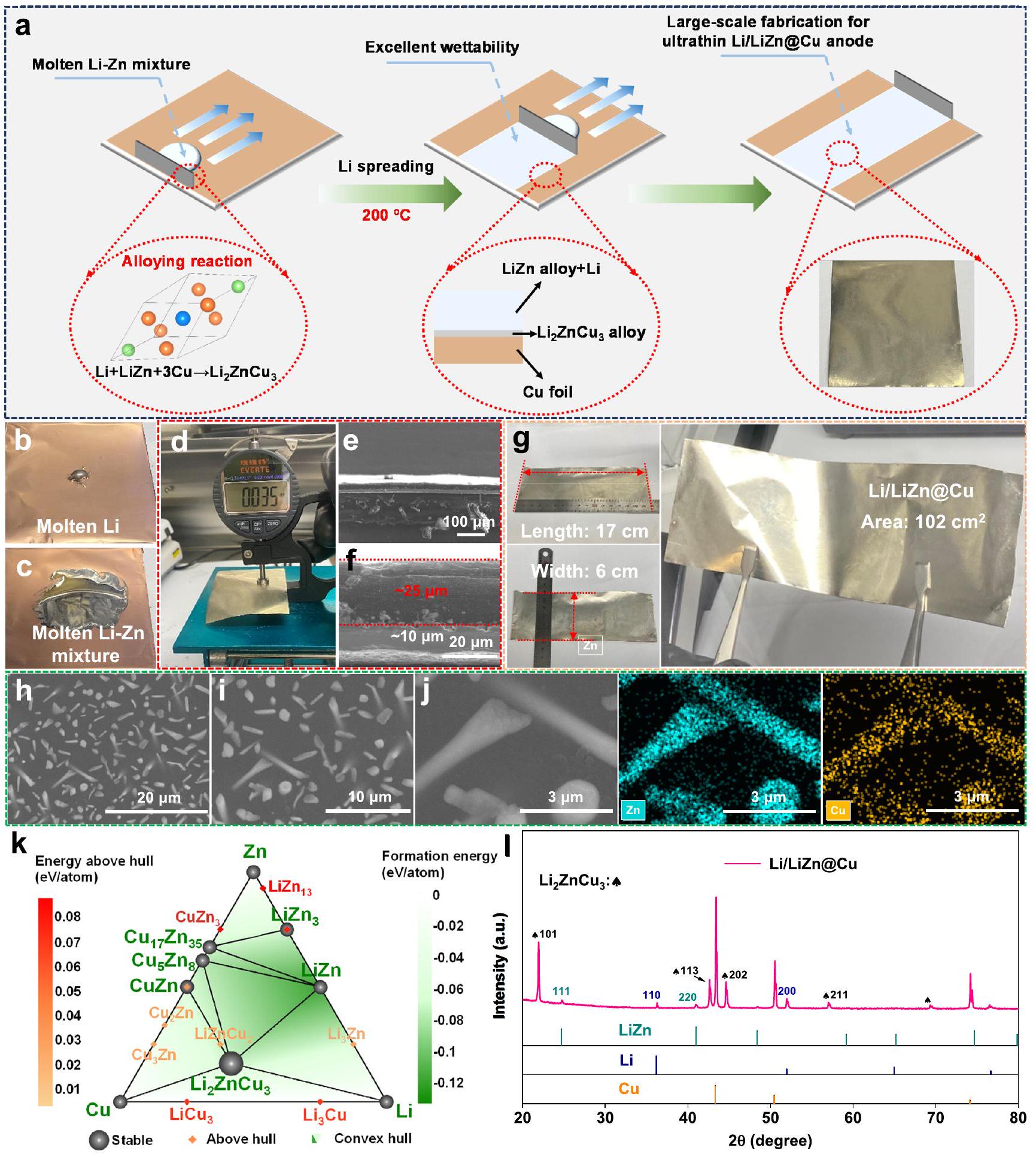
روتين التصنيع للرقائق الرقيقةالأنود موضح في الشكل 1أ. أولاً، يتم تحضير سلف المنصهرخليط ) يتم تصنيعه عن طريق تسخين رقائق الليثيوم والزنك المختلطة (نسبة الكتلة: ) تحت في صندوق قفازات. بعد عملية تحريك شاملة، يتم نقل السلف إلى سطح رقائق النحاس تحتيُلاحظ أنه فيما يتعلق بالتوتر السطحي القوي في الليثيوم المنصهر (صعوبة التمدد)، فإن المنصهريمكن أن ينتشر الخليط بسهولة على رقائق النحاس، حيث يبدو أن إضافة الزنك المعدني تحسن من الاتصالات المتعددة بين الواجهات.النظام كما هو موضح في الشكل 1ب، ج. لذلك، من السهل جداً إعادة تشكيل سمك المادة المنصهرةطبقة على ركيزة النحاس باستخدام شفرة الطبيب. كما هو موضح في الشكل 1d، فإن السمك المتوسط للطبقة الناتجةالأنود حواليطبقة:; ركيزة النحاس: مع كثافةوبنية واجهة Cu كما تم تأكيده بواسطة صور المجهر الإلكتروني الماسح (SEM) في الشكل 1e و f والشكل التكميلية 1. كما هو موضح في الشكل التكميلية 2، فإن مثل هذا الأنود الرقيق Li/LiZn@Cu يوفر سعة نوعية مناسبة من، والتي تتوافق مع كثافات الطاقة الحجمية والوزنية بحوالي و والتي هي تقريبًا 8 و 2 مرات أعلى من الأنود الجرافيتي التجاري كما هو موضح في الجدول التكميلي 1، على التوالي. ما هو أكثر من ذلك، سمك الصبالطبقة قابلة للتعديل (تتراوح من 5 إلى، بما يتوافق مع السعة من 0.89 إلى )، السعات المتاحة منها متوافقة مع معظم الكاثودات كما هو موضح في الأشكال التكميلية 3-5. من ناحية أخرى، حتى عند استخدام رقائق، تصنيع الرقيقةالأنود أيضًا ناجح، مما يسلط الضوء على إمكانية تقليل الكتلة غير النشطة وبالتالي زيادة كل من كثافات الطاقة الحجمية والوزنية كما هو موضح في الأشكال التكميلية 6-8. علاوة على ذلك، فإن هذا الرقيقالأنود أكثر مرونة بالنسبة لرقائق الليثيوم التي يمكن تمديدها بثبات إلى أجهزة تخزين الطاقة المرنة كما هو موضح في الشكل التكميلي 9. ومن المثير للاهتمام بشكل خاص أنه كما هو موضح في الشكل 1 ج، من السهل صب طبقة رقيقة من الليثيوم /أنود معفي المنطقة لإظهار الإمكانية لتوسيع نطاق تطبيق التصنيع لبطاريات الليثيوم أيون.
بالنسبة لسطح النحاس العاري كما هو موضح في الشكل التكميلي 10، فإن الشكل الشبيه بالجزيرة لـيتم عرض الأنود حيث تتوزع العديد من الهياكل الشبيهة بالنانورود والنانودوت بشكل عشوائي على السطح المسطحالمادة الأساسية كما هو موضح في الشكل 1 هـ، و. في الواقع، التفاعل بين الليثيوم والزنك هو تفاعل سبائك إعادة التكوين، مما يعني أنيمكن اعتبارها مزيجًا من المركب بين الفلزات LiZn والليثيوم المعدني عند نطاق تركيز ذرات الليثيوم منإلى. هنا، التركيز الذري لليثيوم في هو . وبالتالي، فإن الهياكل الشبيهة بالأنابيب النانوية والنقاط النانوية تتوافق بشكل رئيسي مع هياكل سبائك LiZn كما هو موضح في الشكل 1j، وهو ما تم التحقق منه من خلال قياس طيف الأشعة السينية المشتتة للطاقة (EDS) لـالسطح، مقدمًا التوزيع التراكمي لعنصر الزنك حول الهياكل النانوية. كما هو موضح في الشكل التكميلي 11، فإن هذه الهياكل النانوية مدفونة بواسطة الليثيوم المعدني، مما يشكل أنود ليثيوم مركب ثلاثي الأبعاد مدعومًا بهياكل السبائك. ومن المثير للاهتمام أن عنصر النحاس موجود أيضًا على الهياكل النانوية، حيث تكون التركيز الذري هو
الشكل 1 | تصنيع أنود Li/LiZn@Cu. أ رسم تخطيطي لعملية التصنيع. قابلية رطوبة Li لـ (ب) Li المنصهر و (ج) خليط Li-Zn المنصهر على رقائق Cu. د السمك، هـ، و صور SEM للمقطع العرضي، ز الحجم، ح، ط صور SEM من الأعلى
صور،الخرائط المقابلة لتقنية EDS للأنود الرقيق Li/LiZn@Cu. k مخطط الطور الثلاثي المحسوب لـنظام عند 473 كلفن. نمط حيود الأشعة السينية (XRD) للأنود الرقيق Li/LiZn@Cu. 10.91% كما هو مدرج في الجدول التكميلي 2. كما هو موضح في الشكل 1k والأشكال التكميلية 12-14، مخطط الطور الثلاثي المحاكى والجهود الكيميائية لـ يتوقع النظام أن يتم إعادة سبك سبيكة LiZn وLi وركيزة Cu وتحويلها إلى ما تم الإبلاغ عنه نادراً سبائك، وهي مرحلة مفضلة للطاقة في نطاق واسع من درجات الحرارة. وبالتالي، تحتوي هذه الهياكل النانوية على LiZn وكمية صغيرة منكما هو موضح في الشكل 11 والأشكال التكميلية 15 و 16، تشير قمم حيود الأشعة السينية (XRD) إلى تعايش سبيكة LiZn (PDF#03-0954)، الليثيوم المعدني (PDF#15-0401)، ركيزة النحاس (PDF#04-0836) والمادة الجديدة المتكونةسبائك في الأنود Li/LiZn@Cu. باستثناء هذه القمم، لم يتم الكشف عن أي قمم معدنية واضحة للزنك تشير إلى عملية سباكة الليثيوم والزنك بشكل كامل. ومن الأهمية الخاصة أنالسبائك توجد بشكل رئيسي عند الواجهة بينطبقة وركيزة النحاس كما هو موضح في الشكل التوضيحي 17. مثل هذا الوجوديمكن أن يساعد السبيكة بشكل أكبر في انتشار المنصهر بسرعةخليط على ركيزة النحاس.
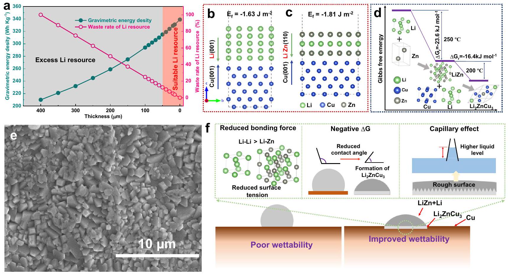
الشكل 2 | أنود مركب ليثيوم اقتصادي عن طريق السبائك. أ تم حساب كثافة الطاقة الجاذبية ومعدل هدر موارد الليثيوم لخلية الكيس مع سماكات مختلفة من أنودات الليثيوم المعدنية. البيانات المستخلصة تستند إلى الجدول التكميلي 4. طاقات التكوين لـ (ب) و (ج) الواجهات. توضيح تخطيطي
تكوين LiZn والسبائك وطاقة جيبس الحرة المقابلة لها ). صورة SEM من الأعلى لـسبائك.العوامل التي تؤثر على قابلية رطوبة الليثيوم مع الليثيوم والزنكعلى ركيزة النحاس.
يظهر هذا الفيلم المختلط متعدد المكونات Li/LiZn@Cu هيكلًا مركبًا فريدًا، يعمل ليس فقط كمواقع توزيع وتبلور غير اتجاهية لليثيوم لتقليل التأثير من البلورات الشجرية الشهيرة، ولكن أيضًا كمصدر لتجديد الليثيوم وإطار للمساهمة في الاستقرار الكيميائي/الكهربائي عند الدورة.
أنود مركب ليثيوم اقتصادي عن طريق السبائك
تظهر الشكل 2 والجدول التكميلي 4 الهدر المحتمل لمصدر الليثيوم مع زيادة السماكة، واستراتيجية تصميم الأنودات المعتمدة على سبائك الليثيوم لبطاريات الليثيوم المعدنية. في الواقع، تنخفض كثافة الطاقة للخلية المعبأة الناتجة أيضًا إذا لم يتناسب الليثيوم الزائد بشكل معقول مع سعة الكاثودات التجارية الحالية كما هو موضح في الشكل 2أ. ومن ثم، فإن تطوير الأنودات الرقيقة المعتمدة على الليثيوم يساهم ليس فقط في الكثافة العالية للطاقة المتوقعة، ولكن أيضًا في الاستخدام الاقتصادي لليثيوم في بطاريات الليثيوم أيون. لتحقيق هذه الغاية، فإن الأنودات الرقيقةتم اقتراح السبائك، وليس معدن الليثيوم النقي بسبب عدم استقرار الليثيوم نفسه، هنا كأنود عملي بشرط فهم جيد لخاصية ترطيب الليثيوم وآليات السبائك.
بشكل أساسي، تتعلق قابلية سائل للالتصاق بالركيزة بعاملين رئيسيين، بما في ذلك توتر السطح لليثيوم المنصهر وملمس السطح للركيزة. أولاً، يمكن أن تعمل سبائك LiZn المذكورة أعلاه على تقليل توتر السطح لليثيوم المنصهر بشكل فعال بسبب التفاعل الأضعف لـفيما يتعلق بـ الروابط، مما يزيد بشكل ملحوظ من قابلية wettability لليثيوم على الركيزة. تفاعل السبائك بين الليثيوم والزنك عند كما يلي:
لاحظ أن الطاقة الحرة جيبس المفرج عنها (يتم تقدير ( ) عند درجات حرارة عالية باستخدام نموذج التعلم الآلي SISSO (الفرز المستقل المؤكد ومشغل التخفيف).. بالمقارنة مع رابطة، قوة الربط لـأصغر، مما يؤدي إلى تقليل التفاعلات الذرية الداخلية والتوتر السطحي للليثيوم المنصهر لتحسين قابلية رطوبة الليثيوم بشكل فعال على المادة الأساسية، متوافقة مع النتائج المبلغ عنها. لذلك، عند التحضير، يمكن أن يتفاعل الليثيوم المنصهر في الموقع مع الزنك لتشكيل سبيكة الليثيوم والزنك المرغوبة، مما يعجل بدوره الانتشار المتجانس لليثيوم الزائد على سطح رقائق النحاس. ثم، تتفاعل سبيكة الليثيوم والزنك الثنائية الجزئية مع النحاس والليثيوم الزائد لتوليد الثلاثيةسبائك. كما هو موضح في الشكل 2ب، ج، ف، فإن طاقات التكوين لـ و تحدد الواجهات على أنها و على التوالي، مما يشير إلى تعزيز الروابط الكيميائية بين النحاس وبالنسبة لذلك بين النحاس وكما هو موضح في الشكل 2d، هذا المحسنواجهة الاتصال تساعد في عملية السبك اللاحقة لـ، ووجود الليثيوم بكميات زائدة فيلإنشاء الثلاثيالمرحلة كما يلي:
في الواقع، هذه التفاعل الطارد للحرارة بين المنصهرالسبائك، والنحاس يسهم في تحسين قابلية رطوبة الليثيوم على الركيزة خلال عملية السبائك.
من وجهة نظر الديناميكا الحرارية، يمكن تحديد قابلية رطوبة الليثيوم من خلال زاوية الاتصال باستخدام المعادلة التالية :
في الذي و تشير إلى زاوية الاتصال بعد أو قبل التفاعل، هو تغيير في طاقة الواجهة بين الصلب والسائل نتيجة التفاعل، وهي طاقة الواجهة بين الغاز والسائل. كلما كانت أصغركلما كانت القابلية للرطوبة أفضل. وبالتالي، فإن السبائك الطاردة للحرارة (السلبية ) من و يمكن أن يقلل منلزيادة قابلية wettability لليثيوم على رقائق النحاس، مما يوفر قوة دافعة إضافية لانتشار الليثيوم المنصهر، بما يتماشى مع التقارير السابقة. بشكل أكثر أهمية، تشكيل يمكن أن تحول السبيكة شكل ورقة النحاس وتُحسن بشكل كبير من خشونتها كما هو موضح في الشكل 2e. الاتصال بين المنصهريمكن أن تكون الخلطة وركيزة النحاس يعتبر حالة وينزل بسبب الواجهة المضغوطة داخل طبقة Li / LiZn و Cu في، مما يمكن أن يحسن من قابلية بلل السطح المحب لليثيوم من خلال زيادة الخشونةمثل هذه الشكل الهرمي لـالسبيكة تظهر الهياكل النانوية الوفيرة لتشكيل تأثير الشعيرات الدموية الفعال، والذي يساهم أيضًا في قابلية رطوبة الليثيوم بواسطة ضغط لابلاس.; ، حيث هو توتر السطح للليثيوم المنصهر و يشير إلى نصف قطر الشعيرات الدموية)، كما هو موضح في الشكل 2e،تحت التأثيرات التآزرية المذكورة أعلاه، زاوية الاتصال لـبين المنصهرالمزيج وركيزة النحاس أصغر بكثير منبين الليثيوم المنصهر وركيزة النحاس كما هو موضح في الشكل التكميلي 18.
بعد كل شيء، عملية قابلية wettability لـ Liالمزيج نحو ركيزة النحاس، حسب أفضل معرفتنا، يختلف كثيرًا عن التقارير الأخرى.خليطباستثناء تقليل التوتر السطحي بواسطةتكوين الروابط، تحسين قابلية رطوبة الليثيوم لـالمزيج يشمل أيضًا تشكيل ثلاثيسبائك عبر تفاعل إعادة سبائك لتسهيل انتشار الليثيوم على ركيزة النحاس، حيث ستساهم التفاعل الحراري المصاحب والشكل الفريد بشكل متكامل في قابلية رطوبة الليثيوم كما هو موضح في الشكل 2f. توفر هذه العملية إمكانية لضمان توزيع موحد وقابل للتعديل في السمك.طبقة على ركيزة النحاس لعملية ترسيب/إزالة الليثيوم المطلوبة.
توصيفات على ترسيب/إزالة الليثيوم
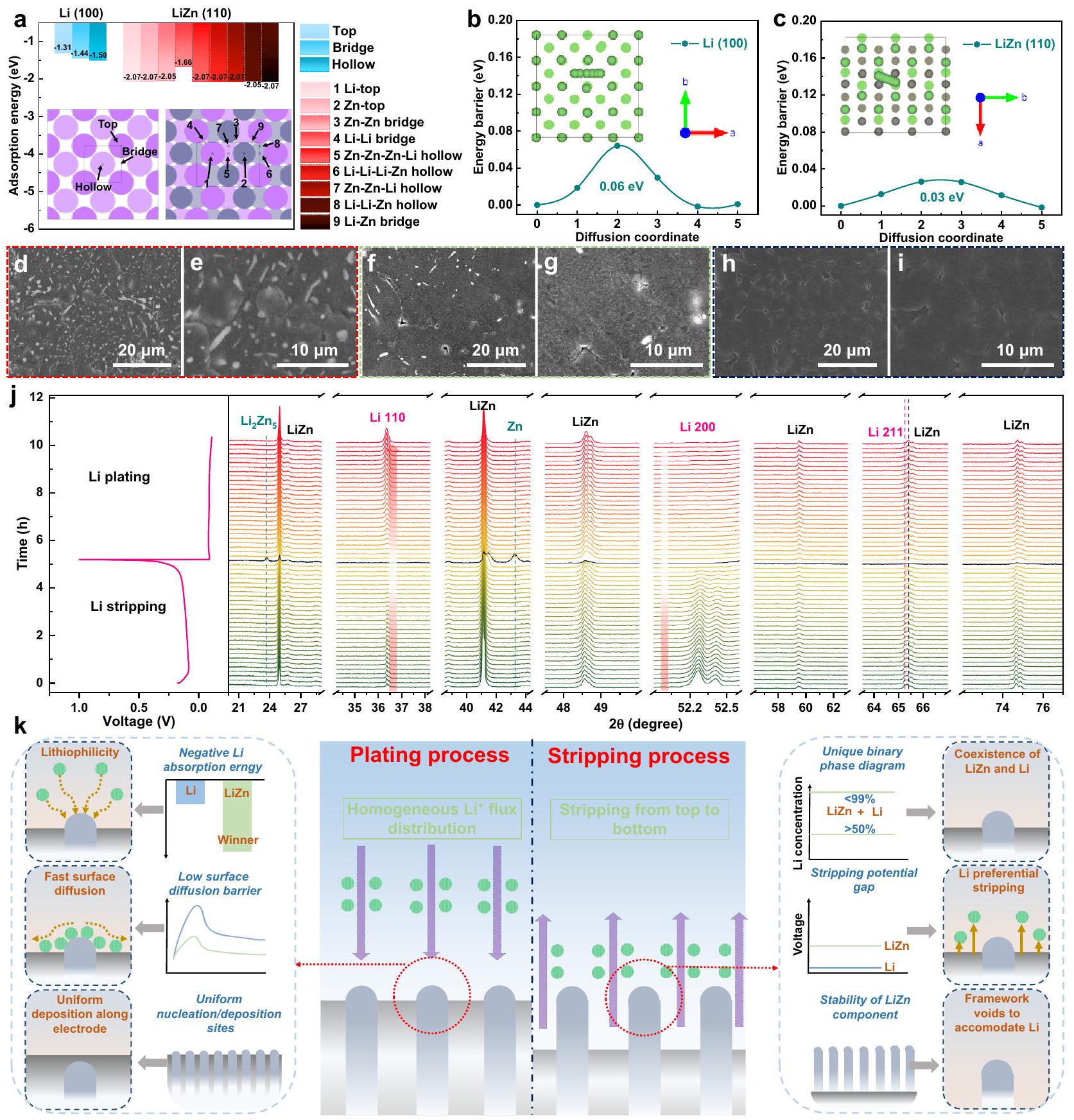
إن انخفاض طاقة امتصاص الليثيوم وحاجز الانتشار على الركيزة أمران أساسيان لتراكم الليثيوم المتجانس وذوبان الليثيوم اللاحق. عندما يكون لدى سطح الركيزة/القطب طاقة امتصاص أكثر سلبية تجاهالأيون (أي، اللثيوم الفائق الجاذبية) سيسهل تشكيل مواقع نوى الليثيوم لتعزيز ترسيب الليثيوم. خلاف ذلك، قد يذوب الليثيوم مرة أخرى في الإلكتروليت، مما يؤدي إلى شكل غير متجانس من نوى/ترسيب الليثيوم.. لذلك، يمكن توقع سلوك ترسيب الليثيوم الموحد إذا كانت مواقع الليثيوم المحبة موزعة بشكل متجانس على السطح. سلوكيات انتشار الليثيوم الجوهرية لـتتم زيارة الأنود أولاً من خلال حسابات DFT، حيث يتم تحديد أسطح Li (100) و LiZn (110) المستقرة لفهم سلوك ترسيب الليثيوم على الليثيوم والمواقع المحتملة لامتصاص على و تظهر الأسطح في الأشكال التكميلية 19 و 20 (الإحداثيات الذرية لواحدالأيون الممتص عند و توجد الأسطح في البيانات التكميلية 1 و 2). كما هو موضح في الشكل 3a، k، فإن طاقة امتصاص الليثيوم لـالسطح هو -2.07 إلكترون فولت، وهو أقل بكثير من -1.50 إلكترون فولت لـالسطح، مما يدل علىالأيونات ستتجمع بشكل تفضيلي على سبيكة LiZn. بالتفصيل، فإن امتصاص ذرات الليثيوم حول مواقع الزنك يظهر طاقات امتصاص أقل بكثير، مما قد يهيمن على عملية ترسيب الليثيوم على السطح. مع تقدم الترسيب، تتوزع جزيئات سبيكة LiZn المحبة لليثيوم بشكل عشوائي كما هو موضح في الشكل.توفير فرصة لترسيب الليثيوم المتجانس لقمع النمو الموجه لبلورات الليثيوم. علاوة على ذلك، فإن حاجز انتشار الليثيوم على طولالسطح هوفقط نصف ذلك على طولالسطح كما هو موضح في الشكل 3ب،على الرغم من أن مثل هذه الحواجز في الانتشار تشير إلى سلوك انتشار الليثيوم الشبيه بالسوائل. إلا أن انخفاض حاجز انتشار الليثيوم يمكن أن يسهل النقل الجانبي لليثيوم لت deposit الليثيوم في جوار الركيزة بدلاً من البروز، مما يخفف من نمو الشجرة البلورية.. بالإضافة إلى ذلك، نظرًا لوجود كمية صغيرة منسبائك فيالطبقة وخصائصها الفائقة في محبة الليثيوم، ستؤثر أيضًا بشكل إيجابي على سلوكيات ترسيب الليثيوم كما هو موضح في الجدول التكميلي 5 والشكل 21. كما هو موضح في الشكل 3d-i، k، من صور SEM لـ Li/بعد ترسيب الليثيوم الكمي، عند ترسيب ليثيوم بمقدار 0.5 مللي أمبير ساعة، تظهر نوى الليثيوم المتجانسة على سطح سبيكة الليثيوم والزنك وتظهر أيضًا عند 1 و، يتم زرع طبقة ليثيوم كثيفة وناعمة علىالأنود بدون نمو واضح للبلورات، في تناقض حاد معالأنود كما هو موضح في الشكل التوضيحي 22 أ، ب.
علاوة على ذلك، فإن توصيف حي XRD يوفر فهماً عميقاً لسلوكيات إزالة/تغطية الليثيوم في الأنود. بسبب الاستقرار الكهروكيميائي الممتاز لـسبائك ولمنع تداخل ركيزة النحاس على إشارات حيود الأشعة السينية كما هو موضح في الأشكال التكميلية 23 و 24، يتم تعيين القطب العامل ليكونالأنود للتبسيط. كما هو موضح في الشكل 3 ج، عند إزالة الليثيوم الأولية (الجهدلا توجد أي تحولات واضحة في القمم أو توليد قمم جديدة لإظهار الاستقرار الكهروكيميائي لسبائك LiZn، بينما يتم إذابة الليثيوم المعدني باستمرار في الإلكتروليت كما يتضح من الانخفاض التدريجي في شدةو (200) قمة. في نهاية إزالة الليثيوم، تتلاشى شدة قمة XRD لسبائك LiZn وتت decomposes جزئيًا إلى Zn و Li ناقص.سبائك مثلمكون (نمط XRD الأسود) عند جهد أعلى من 0.15 فولت بعد 4.5 ساعة كما هو موضح في الشكل 3j. وهذا يعني أنه بسبب الجهد الأكسدي الأعلى لسبائك LiZn بالنسبة للليثيوم المعدني، ستحتفظ سبيكة LiZn بتكوينها وبنيتها البلورية قبل إزالة أيونات الليثيوم المحيطة بشكل كامل لتعمل أولاً كإطار كما هو موضح في الشكل التكميلي 11، ثم كمصدر لليثيوم، مع ترك مواقع نواة وفيرة (مثلوالمحتوي على نقص في الليثيومسبائك) للإيداع غير الاتجاهي لليثيوم لاحقًا. كما هو موضح في الشكل 3k، فإن هذه العملية الهرمية لخلع الليثيوم فيالأنود يحدد عملية تقشير الليثيوم المثالية، والإمداد الضروري بالليثيوم بالإضافة إلى عملية ترسيب الليثيوم القادمة، مشابهًا للإطار من نوع السبيكة المحتفظ به.. ثم عند ترسيب الليثيوم، يتم تجديد سبيكة LiZn بمجرد أن يبدأ الليثيوم في الترسيب كما هو موضح في الشكل 3j. ومن الأهمية الخاصة أن سطح ترسيب الليثيوم يتغير إلى المستوى (110) بدلاً من المستوى الابتدائي (200)، مما يسهل تشكيل شكل الليثيوم المسطح..
الأداء الكهروكيميائي لقطب ليثيوم/ليثيوم زنك@نحاس
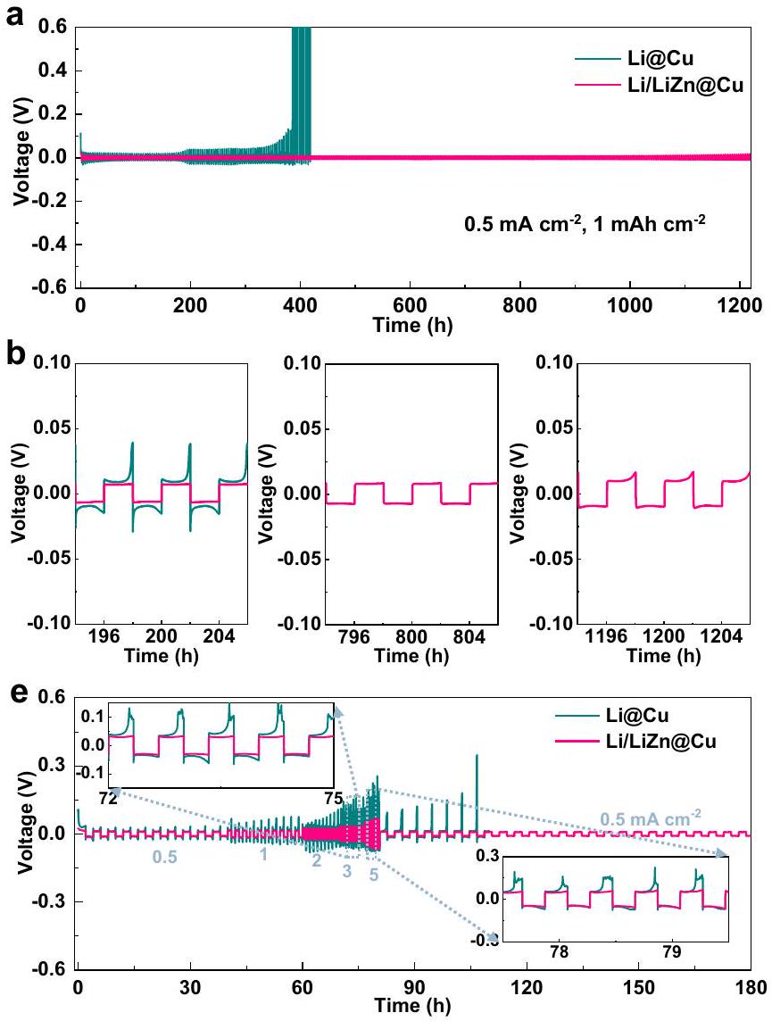
تظهر الشكل 4 الأداء الكهروكيميائي للرقيق و الأنودات باستخدام خلايا متماثلة. السعة المدورة ثابتة عند، مما يتوافق مع تصريف بعمق ، وهو أكبر من ذلك في الأعمال المبلغ عنها كما هو مدرج في الجدول التكميلي 6. كما هو موضح في الشكل 4a، كلا الخليتين تظهران ملفات جهد مستقرة، بينما الفرق الملحوظ هو أن الجهد الزائد لـ Li /أقل من ذلك منالأنودات في الدورات التسعين الأولى في. يمكن أن يُعزى ذلك إلى حاجز أعلى لتكوين/ترسيب الليثيوم على السطح الناتج عن عملية واجهة ضعيفة كما هو موضح في طيف التحليل الكهربائي للمعاوقة (EIS) في الأشكال التكميلية 25 و26 والجدول التكميلية 7، حيث يظهر الشكل الشجيري وغير المتساوي السماكةالأنود لديه حالة غير مستقرة في البدايةواجهة الإلكتروليت مع SEI الأعلى ) وانتقال الشحنة ( مقاومات أكثر من تلك الخاصة بـالأنود. علاوة على ذلك، فإن استقطاب الجهد لـيزداد الأنود عند حوالي 192 ساعة وتحدث فشل الخلية المتماثلة بعد كما هو موضح في الشكل 4a و 4b. على النقيض الحاد، فإن الخلية المتماثلة من أنود Li/LiZn@Cu تقدم أداءً مستقرًا خلال 1200 ساعة استجابةً لعملية الطلاء/الإزالة المتجانسة المذكورة أعلاه وواجهة Li/الإلكتروليت القوية التي تتمتع بها الخصائص الممتازة لجذب الليثيوم، منخفضة حاجز طاقة انتشار الأيونات، ووظيفة شبيهة بالإطار لسبيكة LiZn. حتى عند كثافة تيار أعلى من، الـلا يزال الأنود يقدم أداءً كيميائيًا كهربائيًا مشابهًا دون تقلبات في الجهد على مدى 690 ساعة كما هو موضح في الشكل 4c، d. لاحظ أن هذا الأداء الاستثنائي للرقائقأنودأفضل حتى من رقائق الليثيوم التجارية ) كما هو موضح في الأشكال التكميلية 27، 28.
قدرة المعدل لـ و ثم يتم تنفيذ الخلايا المتماثلة تحت كثافات تيار مختلفة من، و بسعة دراجة ثابتة. كما هو موضح في الشكل 4e، الـتظهر الخلية بشكل ساحق ملفات جهد أكثر استقرارًا وفوق جهد أقل من تلك الخاصة بـالخلية طوال عملية الدورة بأكملها. بعد اختبار المعدل، فإن الجهد الزائد لـيمكن أن تعود الخلية المتماثلة أيضًا إلى حالتها الأولية بشكل متناسبمختلف تمامًا عن
الشكل 3 | سلوك ترسيب/إزالة الليثيوم على أنود Li/LiZn@Cu. أ امتصاص الليثيوم الطاقات على و الأسطح. حواجز الانتشار لليثيوم على طول (100) و (c) أسطح LiZn (110). صور SEM لأنود Li/LiZn@Cu بعد Li
ترسيب عند (د، هـ) 0.5، (ف، ج) 1، و (ح، ط). تحليل XRD في الموقع و (k) توضيح تخطيطي لعمليات إزالة الليثيوم وتخزينه في أنود Li / LiZn@Cu. خلية متماثلة في نفس. علاوة على ذلك، توضح الشكل 4f اختبارات الكفاءة الكولومبية المتوسطة (ACE) لتقييم قابلية عكس سلوكيات الطلاء والتجريد المتكررة لليثيوم في الخلايا المتماثلة. بالمقارنة مع الكفاءة الكولومبية المتوسطة المنخفضة لـلـالخلايا، تقدم خلية Li/LiZn@Cu كفاءة عالية تبلغ 99.2% بعد 50 دورة عند، مما يشير إلى استخدام عالي لليثيوم مع تراكم منخفض لـ “ليثيوم ميت”.
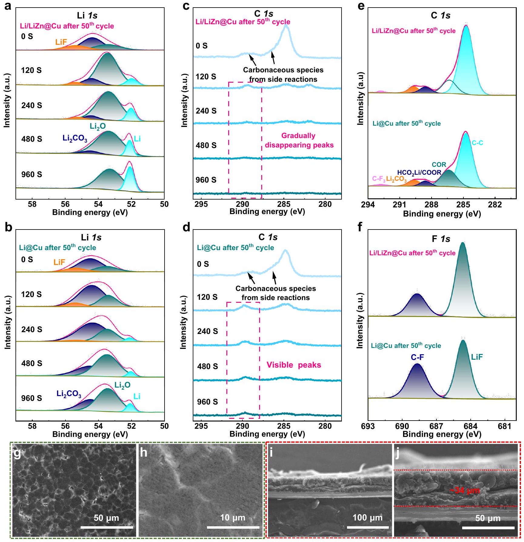
لفهم سلوك ترسيب الليثيوم الممتاز وإزالته،تم إجراء تحليل طيف الإلكترون الضوئي بالأشعة السينية (XPS) المنقوش بالأيونات بعمق على أقطاب Li/LiZn@Cu وLi@Cu التي تم دورتها. كما هو موضح في الشكل 5a، فإن الليثيوم النقيطيف XPS للدورةيمكن تفكيكه إلى، و ، وهو مشابه لذلك الذي تم تدويرهالقطب الكهربائي كما هو موضح في
الشكل 5ب. بينما، محتوى LiF فيأعلى من الـمن المحتمل أن يعطي تأثيرًا مربحًا للزي الموحدتوزيع التدفق وعزل الإلكترونات، والذي تم التحقق منه أيضًا في طيف F 1 s كما هو موضح في الشكل 5f. ما يثير الاهتمام بشكل خاص هو أنه عند وقت النقش 120 ثانية، تم تخصيص قمة جديدة عند 52.0 إلكترون فولت للليثيوم المعدني فيبينما لا يظهر في، مما يشير بشكل معقول إلى نمو SEI الأرق لـ Li/LiZn@Cu مقارنةً بـالأقطاب الكهربائية. إلى جانب النقش، يظهر الليثيوم المعدني في كلا الأقطاب، ولكن كمية “الباراسيتيكمن الواضح أن التفاعلات الجانبية أعلى فيأقل من ذلك فيأقطاب النحاس. الشكل 5c-e يوضح الخصائص Cتصل إلى 284.8 ، 286.4 ،، و 292.8 إلكترون فولت التي تُعرف بأنها C-C، COR (R: الجذور الحرة)،، و على التوالي. خاصةً,
الشكل 4 | أداء الخلايا المتماثلة الرقيقة و الأنودات. دورة جلفانية ثابتة وملفات جهد مفصلة عند (أ، ب) و (ج، د) معدل الأداء عند الكثافات الحالية من
0.5 إلىمعالرسوم التوضيحية هي ملفات تعريف الجهد التفصيلية عند 3 و الكفاءة الكولومبية المتوسطة (ACE) لـ 50 دورة من ترسيب/إزالة الليثيوم في .
الـ Cتختفي القمم التي تزيد عن 286 إلكترون فولت تقريبًا عند 480 ثانية فيLiZn@Cu، بينما كان موجودًا بشكل واضح في Li@Cu طوال عملية النقش، والتي تت correspond إلى الأنواع الكربونية (COR،، إلخ.) بشكل رئيسي من التفاعلات الجانبية غير القابلة للعكس. وهذا يكشف أن سبائك الزنك تؤثر على تشكيل SEI وكذلك بناء واجهة Li/LiZn@Cu/الإلكتروليت لحماية الليثيوم بفعالية ضد تآكل الإلكتروليت وتوفير سلوك طلاء/إزالة الليثيوم القابل للعكس لفترة طويلة من دورة الحياة كما هو موضح في الشكل 4. بالإضافة إلى ذلك، لا توجد قمم XPS في طيف Li/LiZn@Cu حتى بعد 960 ثانية من النقش، مما يشير إلى طبقة ترسيب ليثيوم متجانسة موجهة بواسطة ركيزة سبيكة LiZn بسبب الخصائص الممتازة لجذب الليثيوم كما هو موضح في الشكل التكميلي 29.
شكل والشكل التوضيحي التكميلي 30 يظهر تطور مورفولوجيا السطح لأقطاب Li@Cu و Li/LiZn@Cu بعد تكرار عملية الطلاء/الإزالة بالليثيوم. كما هو موضح في الشكل التوضيحي التكميلي 30a و b، يتم ملاحظة طبقة SEI سميكة مع تشققات كبيرة على سطح النحاس بعد 50 دورة في و . يتكون هذا SEI السميك والمقشر من “لي الميت” المتراص، والذي ينشأ على الأرجح من الدندريت غير المرغوب فيه لليثيوم والتمزق المتكرر لـ SEI. علاوة على ذلك، فإن صور SEM للمقطع العرضي لـتظهر شكل واجهة متدهور تمامًا، مما سيعيق عملية نقل الكتلة لنقل الأيونات/ الإلكترونات كما هو موضح في الشكل التكميلي 30c، d. في المقابل، طبقة ترسيب متجانسة ( ) يتكون من حبيبات ليثيوم مضغوطة بشكل كبير على سطح Li/LiZn@Cu كما هو موضح في الشكل.. هذا يدل على أن سبيكة LiZn متعددة الوظائف يمكن أن تنظم بشكل جيد ترسيب الليثيوم المتجانس وتقيّد التمدد الحجمي غير القابل للتحكم لتعزيز الأداء الكهروكيميائي. يمكن أن يُرى من تحليل EIS أنه كما هو موضح في الشكل التكميلي 31، فإن نصف الدائرة عند التردد العالي يتوافق إلى نقل أيونات الليثيوم داخل طبقة SEI )، الذي ينخفض ويستقر تقريبًا في قطب Li/LiZn@Cu، بينما يصبح أصغر أولاً ثم أكبر من الدراجة إلىدورة، تعكس تدهور عملية الديناميكية للواجهة في.
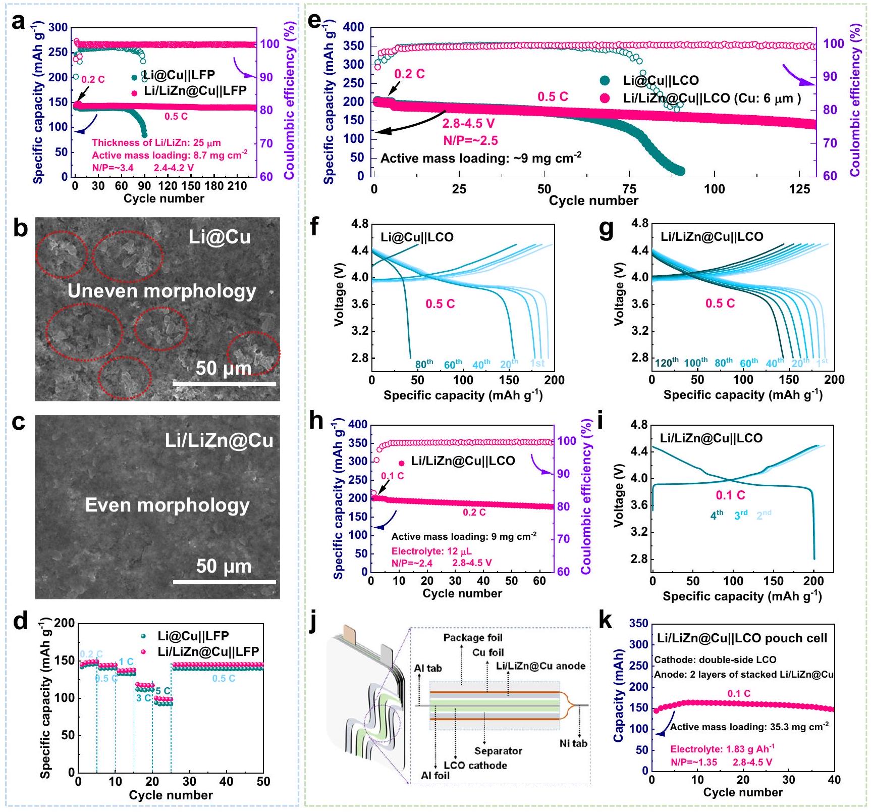
تظهر الشكل 6 أداء الخلية الكاملة مع الرقيقالأنود، حيث الكاثود هو (LFP) بمتوسط تحميل كتلة نشطة من (المقابل لـ ) ونسبة السعة بين الأنود والكاثود (نسبة N/P) تم تعيينها لتكون قيمة منخفضة مقارنة بمعظم القيم المبلغ عنها كما هو موضح في الجدول التكميلي 6. كما هو موضح في الشكل 6a والشكل التكميلي 32، فإن خلية Li/LiZn@Cu||LFP تقدم ليس فقط كفاءة كولومبية مستقرة منوانخفاض طاقة ضئيل طوال الدورة الكاملة، ولكن أيضًا عمر طويل يمتد لأكثر من 230 دورة مع تحسين الاحتفاظ بالسعة. في تناقض حاد، الـيمكن لخلية كاملة تعتمد على الأنود أن تعمل عادةً لمدة 70 دورة فقط، ثم تتلاشى بسرعة إلىبعد 80 دورة. مثل هذا الأداء الضعيف للدوراتتُنسب الخلية مباشرةً إلى فشل الواجهة الناتج عن نمو الشجيرات الزائد، في حين أن شكللا يزال سلسًا وغير تالف أثناء الدورة كما هو موضح في الشكل 6ب، ج والشكل التكميلي 33. بالإضافة إلى ذلك، بالنظر إلى أن إدخال الشكل الوعر لليثيوم و”الليثيوم الميت” في الأنود Li @Cu أثناء التحضير الكهروكيميائي أمر لا مفر منه، مما سيؤثر سلبًا على اختبارات الخلايا الكاملة، فإن الأسطوانة الميكانيكية القائمة على الرقيق-سميك Liتم تعيين الأنود ليكون مجموعة التحكم كما هو موضح في الشكل التكميلية 34. عند اقترانه بـ LFP عالي التحميل (، الذي يتوافق مع )، الأداء البارز لـ تُورَث الخلية الكاملة أيضًا، حيث تُظهر احتفاظًا محسّنًا بالسعة لـوعمر طويل بالنسبة لأولئك الذينو م-
الشكل 5 | التحليل بعد الوفاة للخلايا المتماثلة بعد دورة. أ طيف XPS لـ Li/LiZn@Cu الأنود في أوقات حفر مختلفة. ب Li 1s، د C 1s طيف XPS لـالأنود في أوقات نقش مختلفة. هـ, ف طيف XPS
من و أنودات بدون حفر.عرض علوي وصور SEM للمقطع العرضي لأنود Li/LiZn@Cu بعد الدورة. الخلايا كما هو موضح في الشكل التوضيحي 34o. بعد ذلك، يتم تنفيذ أداء المعدل لـ Li/LiZn@Cu||LFP كما هو موضح في الشكل 6d، حيث يقدم Li/LiZn@Cu||LFP سعات تفريغ عالية من، و في، و5C، على التوالي، أعلى من تلك الخاصة بخلية Li@Cu||LFP الكاملة كما هو موضح في الشكل التكميلي 35.
علاوة على ذلك، يتم فرض ظروف تشغيل عالية الطلب علىالأنودات. من خلال استبدال-طبقة Li/LiZn بسماكة 10 أو-سميكالطبقات، نسب N/P للمجمع كما هويمكن تقليل الخلايا أكثر إلىأو 0.7. عادةً، يمكن لخلايا Li/LiZn@Cu||LFP ذات نسب N/P المنخفضة أن تحافظ على سعات متوسطة عالية تبلغ 144 وأكثر من 80 و 60 دورة عند 0.5 درجة مئوية كما هو موضح في الأشكال التكميلية 36، 37. في هذه الأثناء، الخلية الكاملة مع الكاثود ) يتم تدويره تحت نافذة جهد من ، الذي يظهر أيضًا سعة أولية عالية منواحتفاظ جيد بالسعة كما هو موضح في الشكل التوضيحي 38. كما هو موضح في الشكل 6e، فإن الخلية الكاملة مع الأنود Li/LiZn@Cu تتمتع باستقرار دوري معزز واحتفاظ بالسعةبعد 125 دورة في. بينما مع الـالأنود،تظهر الخلية الكاملة سعة محددة مشابهة في أول 50 دورة ولكنها تصاحب فقدانًا مستمرًا في السعة في الدورات اللاحقة. تدهورتُحفز الخلية بشكل رئيسي من خلال نقص الليثيوم المحدود وتراكم الطبقة السطحية غير النشطة، مما يفرض حاجزًا كبيرًا لـالنقل عبر SEI
الشكل 6 | الأداء الكهروكيميائي لـ و خلايا ممتلئة. أداء ركوب الدراجات و خلايا ممتلئة بنسبة N/P من عند 0.5 C بين 2.8 و 4.2 فولت. صور SEM من الأعلى لـ (ب) و (ج) الأنودات بعددورة في الخلايا الكاملة المعتمدة على LFP. أداء المعدل و خلايا كاملة. سمك رقائق النحاس هو . أداء ركوب الدراجات و ( ) ملفات الجهد المقابلة لـ و خلايا ممتلئة بنسبة N/P منعند 0.5 درجة مئوية بين 2.8 وأداء ركوب الدراجاتخلية كاملة مع إلكتروليت رقيق من و الملفات الجهدية المقابلة للدورات المختارة عند 0.1C.j التوضيح التخطيطي وأداء الدراجات المقابل لليثيوم /خلية كيس. سمك رقائق النحاس هو. ويزيد تدريجياً من تذبذب الجهد كما هو موضح في الشكل 6f، g. لتحسين كثافة الطاقة بشكل أكبر، يتم تقليل الإلكتروليت إلى لكل خلية. كما هو موضح في الشكل 6h وi والجدول التكميلي 8، فإن المنتج المحضر تقدم الخلية الكاملة سعة تفريغ عالية منعند 0.1 درجة مئوية، مما يتوافق مع طاقة وزنية قدرهاإذا اعتبرنا فقط الكتلة النشطة للقطب السالب والقطب الموجب، فإنها أعلى بكثير من بطاريات الليثيوم أيون التجارية.
علاوة على ذلك، مستوى 0.16 أمبير ساعةتم تعبئة خلية الكيس للتحقق من تفوق الدورة في الظروف الحقيقية كما هو موضح في الشكل التكميلي 39، الشكل 6j، k، والجدول التكميلي 9. تتكون خلية الكيس من جانبين مفردين.أنودات وقطب كاثود LCO مزدوج الوجه (تحميل الكتلة النشطة: )، حيث يكون نسبة N/P ومقدار الإلكتروليت هويمكن لخلية مكدسة مثل هذه تحتوي على طبقتين فقط أن تحقق كثافة طاقة عالية من، متجاوزًا معظم بطاريات الليثيوم أيون العملية المتاحة كما هو موضح في الجدول التكميلي 9. في الواقع، إذا اعتبرنا أداء هذه الخلية الكيسية كمرجع، يمكن زيادة كثافة الطاقة بشكل أكبر إلىحوالي 10 مزدوجة الجوانب المربوطةالقطب السالب كما هو موضح في الجدول التكميلي 10.
الذي تم تنظيمه بشكل جيد أخيرًاتظهر الأنود الكيمياء الكهربائية لليثيوم الهرمية أنها متوافقة جيدًا مع بطاريات الليثيوم أيون عالية الأداء. عند الشحن،تعمل الأنود أولاً كمصدر لليثيوم لإقامة عملية تقشير متساوية لليثيوم. ثم، في نهاية الشحن، يساهم تفكيك جزيئات ليثيوم الزنك بشكل إضافي في استخراج الليثيوم، مما يلعب فعليًا دور تعويض الليثيوم في دورة البطارية، وهو ما له تأثير عميق على التطبيق العملي لـ المواد المتاحة ذات كثافة الطاقة العالية، مثل السيليكون أوالأنودات المعتمدة على الزنك والكاتودات الطبقية عالية الكثافة المعتمدة على NCM. علاوة على ذلك، عند التفريغ، سيتشكل سبيكة LiZn في البداية، ثم تتبعها ترسيب متجانس لـ Li المنظم بواسطة سبيكة LiZn مع استمرار الدورة. لقد تم التحقق بلا شك من قابلية عكسية لهذه العملية المثيرة من خلال الكيمياء الكهربائية المذكورة أعلاه وخصائص XRD في الموقع. توفر هذه النتائج طريقًا مثمرًا نحو استخدام أنودات Li المعدنية، واستراتيجية Li التكميلية، وبطاريات Li المعدنية عالية الكثافة السائدة.
نقاش
في الختام، فإن الأنودات الرقيقة Li/LiZn@Cu ذات الأحجام الكبيرة ( ) وسماكات/سعات قابلة للتعديل من, ) يتم تصنيعها بنجاح من خلال نهج سهل ومنخفض التكلفة لبطاريات الليثيوم أيون ذات كثافة طاقة عالية. بفضل سبيكة LiZn، يظهر الأنود الرقيق Li/LiZn@Cu مواقع وظيفية سطحية متجانسة ووفيرة لتحفيز عملية إزالة/تراكم الليثيوم، ويقدم كيمياء كهربائية هرمية لتنظيم الشكل الخالي من الشوائب وواجهة قوية بين الليثيوم والكهارل. كما هو متوقع، لا يظهر الأنود Li/LiZn@Cu فقط استقرارًا ممتازًا في الدورة على مدى 1200 ساعة عندفي الخلية المتماثلة، ولكنها تدرك أيضًا عمرًا طويلاً يصل إلى 230 دورة تحت نسبة N/P مناسبة عند اقترانها بقطب LFP. علاوة على ذلك، بطارية ذات كثافة طاقة عالية منعند احتواءه على 10 طبقات مكدسة) يتم الحصول عليه في خلية كيسية قائمة على LCO، تتكون من الإلكتروليت النحيف (نسبة N/P المنخفضة (1.35)، ورقة النحاس الرقيقة القائمة على Li/LiZn@Cu كأنود، وكاثود LCO مزدوج الجوانبتكنولوجيا سبائك واعدة مثل هذه للأنودات المعدنية الرقيقة من الليثيوم تفتح روتينًا عمليًا وواعدًا لبطاريات الليثيوم المعدنية عالية الأداء وكثافة الطاقة في المستقبل.
طرق
تحضير الأنود الرقيق من الليثيوم
تم تصنيع أنود Li/LiZn@Cu الرقيق من خلال عملية صب باستخدام شفرة الطبيب، وتم تنفيذ جميع الخطوات في صندوق القفازات (MBRAUN، محتويات “ و كانت أقل من 0.1 جزء في المليون). أولاً، تم خلط رقائق الليثيوم والزنك المصقولة معًا (نسبة الكتلة: ) وتسخينها إلى في حاوية من الفولاذ المقاوم للصدأ. ثم، سيتحد الليثيوم المنصهر مع رقائق الزنك لتشكيلخليطسبائك). بعد التحريك الكامل، تم نقل المزيج المنصهر إلى سطح رقائق النحاس (درجة الحرارة: ). بسبب تفاعل السبائك الإضافي ( ، و Cu ) وانخفاض التوتر السطحي لـ LiZn المتكون، فإن Li / الرقيق كميًايمكن تصنيع الأنود بسهولة بمساعدة طريقة شفرة الطبيب على رقائق النحاس. بالإضافة إلى ذلك، يمكن الحصول على القطب الكهربائي e-Li/LiZn@Cu بعد إزالة الطلاء.طبقة مع الكحول. للحصول على الرقيقةتم تجميع أنود، خلية نصفية تستخدم رقائق النحاس كإلكترود عمل ورقائق الليثيوم كإلكترود مضاد، ثمتمت الطلاء الكهربائي على سطح النحاس عندكان المحلول الكهربائي 1 م من ليثيوم بيس(ثلاثي فلوروميثان سلفونيل) إيميد (LiTFSI) في 1,3-ديكسيولان (DOL)/1,2-ثنائي ميثوكسي إيثان (DME) ) مع . بعد تفكيك نصف الخلية وشطف ورقة النحاس المطلية بالليثيوم باستخدام DOL، يتم تحضير تم الانتهاء من الأنود. الأنود الرقيق M-Li@Cu (السماكة: -سميكتم شراء رقائق النحاس بسماكة – من شركة الصين للطاقة الليثيوم المحدودة.
توصيف المواد
تم الحصول على صور SEM باستخدام مجاهر الإلكترون الماسح ذات الانبعاث الميداني HITACHI SU5000. لمراقبة الأشكال السطحية أو المقطع العرضي للأقطاب الكهربائية المعاد تدويرها، تم شطفها بـ DOL لإزالة الإلكتروليت المتبقي مسبقًا وتجفيفها في صندوق القفازات. تم إجراء قياسات XRD عبر أجهزة قياس الأشعة السينية Rigaku SmartLab و Bruker D8 Advance.الإشعاع. إلى لتقليل تأثير الهواء على الليثيوم شديد التفاعل، تم تغطية سطح عينات Li / LiZn@Cu بشريط كابتون قبل قياسات XRD. تم استكشاف طيف XPS المتعمق من خلال جهاز Thermofisher Scientific ESCALAB Xi+ مع أشعة ألومنيوم K أحادية اللون.الإشعاع. تم معالجة جميع العينات في صندوق القفازات ونقلها إلى غرفة XPS باستخدام صندوق نقل.
قياس حي XRD
تم إجراء تحليل حي باستخدام حيود الأشعة السينية (XRD) على جهاز حيود الأشعة السينية Bruker D8 Advance.الإشعاع) مع وضع المسح المتتابع (نطاق:إلىكانت الكاثود والأنود متطابقتين وتم تحضيره من خلال تبريد المادة المنصهرةخليط ثم ضغطه في رقائق رقيقة (Li/LiZn). ثم تم تجميع رقائق Li/LiZn المشكّلة في خلية متماثلة في خلية محلية الصنع مع نافذة من البريليوم لمزيد من التوصيف باستخدام حيود الأشعة السينية (XRD). في Lille في الموقع الخلية، كانت الكاثود e-Li/LiZn@Cu (سمك النحاس: ) وكان الأنود عبارة عن رقائق ليثيوم. كان الإلكتروليت 1 مولي من LiTFSI في DOL/DME ( مع.
القياسات الكهروكيميائية
تم التحقيق في جميع القياسات الكهروكيميائية باستخدام خلايا عملة من نوع CR2025 وتمت على نظام اختبار البطاريات LANHE (CT 3002A). في اختبارات الخلايا المتماثلة، تم استخدام قطبين متطابقين ( أو ) كقطب مضاد وقطب عمل. في اختبارات الكفاءة الكولومبية المتوسطة (ACE)، تم تدوير الخلايا المتماثلة مع أقطاب مختلفة أولاً 50 دورة تحت ، ثم تم إزالة جميع الليثيوم المتبقي عند حتى وصلت الجهد إلى 1 فولت. يمكن حساب قيمة ACE كما في الصيغة التالية :
حيث هو رقم الدورة، و هو السعة السطحية الأصلية للقطب المختبر، و هو السعة السطحية الثابتة المستخدمة في الدورات، و هو السعة السطحية النهائية للقطب المختبر. تم إجراء اختبارات EIS للخلايا المتماثلة على محطة عمل كهروكيميائية (Princeton Applied Research، PARSTAT MC) مع نطاق تردد من 200 كيلو هرتز إلى 0.1 هرتز. كانت الإلكتروليت المستخدمة في الاختبارات المذكورة أعلاه 1 M LiTFSI في DOL/DME () مع . في اختبارات الخلايا الكاملة، تم تحضير جميع الكاثودات باستخدام طريقة صب الشفرة. بالنسبة لكاثود LFP مع ، كانت نسبة الكتلة من LFP، والكربون الأسود، وفلوريد البولي فينيليدين (PVDF) 8:1:1. تم توفير كاثود LFP بتحميل كتلة أعلى من بواسطة Kejing (نسبة الكتلة من LFP: 93.4%). بالنسبة لكاثود LCO، كان تحميل الكتلة (نسبة الكتلة من LCO: ). تم تدوير جميع الخلايا الكاملة أولاً 5 دورات عند 0.2 أو 0.1 C للتفعيل قبل الاختبارات الإضافية. كانت الإلكتروليت للخلايا الكاملة 1 M فوسفات الليثيوم الهيكلي () في كربونات الإيثيلين (EC)/كربونات ثنائي الميثيل (DMC)/كربونات إيثيل ميثيل (EMC) () مع كربونات الفلورو إيثيلين (FEC). ما لم يُذكر خلاف ذلك، كانت كمية الإلكتروليت للخلايا من نوع العملة . في اختبار الخلايا الكيسية، كان كاثود LCO مزدوج الجانب المستخدم يمتلك تحميل كتلة أعلى من (نسبة الكتلة من LCO: )، وكان الحجم المطبق . تم تعيين نافذة الجهد التشغيلي والسرعة كـ و0.1 C. من الجدير بالذكر أن عملية الشحن تضمنت عمليتين: كانت الخطوة الأولى عملية شحن جلفانية عند 0.1 C حتى وصل الجهد إلى 4.5 فولت، بينما كانت الخطوة التالية عملية شحن بجهد ثابت حتى انخفض معدل الشحن إلى 0.03 C. يتم عرض المعلومات التفصيلية في الجداول التكميلية 9، 10. تم حساب كثافات الطاقة (Wh ) لخلايا العملة والخلايا الكيسية بواسطة الصيغة التالية:
حيث هو الطاقة المحددة للخلايا ()، و هو الطاقة المفرغة لكل وحدة مساحة المقدمة من برنامج معالجة البيانات لنظام اختبار البطاريات LANHE، و هو الوزن الكلي لكل وحدة مساحة بناءً على مجموع كيس الخلايا الكيسية، والفاصل، والإلكتروليت، وجامع التيار، والكاثود، والأنود. تم إجراء جميع القياسات الكهروكيميائية في الحاضنة عند .
الحسابات النظرية
تم استخدام حزمة محاكاة فيينا Ab Initio (vasp.5.4.4) المعتمدة على موجات معززة متوقعة (PAW) لإجراء حسابات من المبادئ الأولى. تم اعتماد تقريب التدرج العام (GGA) في معلمة دالة Perdew وBurke وErnzerhof (PBE) لوصف تفاعل تبادل الإلكترونات. تم تطبيق طاقة قطع قدرها 450 eV و-مركز -نقطة شبكة، على التوالي. تم إجراء تحسينات هندسية حتى وصلت معايير التقارب للطاقة والقوة إلى و، على التوالي. تم تنفيذ سمك الفراغ قدره لجميع هياكل الشرائح لمنع التفاعل بين الصور الدورية. تم حساب حواجز هجرة أيونات الليثيوم بواسطة طريقة تسلق الصورة المنزلق المرن (CINEB) مع 4 صور كحالات وسيطة، حيث تعتبر محاكاة CINEB مكتملة عندما تكون قيمة القوة لكل ذرة أقل من . تم استخدام شريحة مكونة من 8 طبقات محسنة لحساب حواجز هجرة أيونات الليثيوم، حيث تم تثبيت الطبقات الأربع السفلية في مواقع الكتلة بينما تم السماح لجميع الطبقات الأخرى بالاسترخاء. تم بناء الهياكل البلورية باستخدام برنامج VESTA . تم بناء مخططات الطور التركيبية باستخدام وحدة phase_diagram من Pymatgen . يمكن تقدير الطاقة الحرة Gibbs G(T) لتكوين المواد الصلبة عند درجات حرارة عالية (200 أو ) باستخدام نموذج التعلم الآلي SISSO (تصفية الاستقلال المؤكد ومشغل التخفيف) . ويمكن حساب الطاقة الحرة Gibbs لكل ذرة () بين المتفاعلات والمنتجات كما يلي:
تم وصف طاقة امتصاص الليثيوم كما يلي:
حيث هو الطاقة الكلية لهيكل الشريحة مع امتصاص ليثيوم واحد على السطح، و هو الطاقة الكلية لهيكل السطح، و هو الطاقة الكلية لليثيوم الواحد.
يمكن حساب طاقات تشكيل الواجهة لـ و أنظمة واجهة LiZn(110) كما يلي:
حيث هو النظام الكامل الذي يحتوي على الواجهة، و و تشير إلى الشرائح المنفصلة ( و الشريحة)، و تشير إلى المنطقة الواجهة.
يمكن الحصول على الطاقة السطحية لـ كما يلي:
حيث هو الطاقة لنماذج الشرائح المسترخية دون قيود على موضع الذرات، و هو الطاقة الكلية للهيكل الكتلي، وA هي مساحة السطح.
توفر البيانات
يعلن المؤلفون أن جميع البيانات التي تدعم نتائج هذه الدراسة متاحة ضمن الورقة وملفات المعلومات التكميلية الخاصة بها. جميع البيانات الخام التي تم إنشاؤها خلال الدراسة الحالية متاحة من المؤلفين المعنيين عند الطلب. يتم توفير بيانات المصدر مع هذه الورقة.
References
Chu, S., Cui, Y. & Liu, N. The path towards sustainable energy. Nat. Mater. 16, 16-22 (2017).
Liu, B., Zhang, J.-G. & Xu, W. Advancing lithium metal batteries. Joule 2, 833-845 (2018).
Du, G. et al. Low-operating temperature, high-rate and durable solid-state sodium-ion battery based on polymer electrolyte and Prussian blue cathode. Adv. Energy Mater. 10, 1903351 (2020).
Albertus, P., Babinec, S., Litzelman, S. & Newman, A. Status and challenges in enabling the lithium metal electrode for high-energy and low-cost rechargeable batteries. Nat. Energy 3, 16-21 (2018).
Lin, D. C., Liu, Y. Y. & Cui, Y. Reviving the lithium metal anode for high-energy batteries. Nat. Nanotechnol. 12, 194-206 (2017).
Wang, Z. et al. Insights into the deposition chemistry of Li ions in nonaqueous electrolyte for stable Li anodes. Chem. Soc. Rev. 50, 3178-3210 (2021).
Wu, Z. et al. Growing single-crystalline seeds on lithiophobic substrates to enable fast-charging lithium-metal batteries. Nat. Energy 8, 340-350 (2023).
Xiao, J. et al. Understanding and applying coulombic efficiency in lithium metal batteries. Nat. Energy 5, 561-568 (2020).
Cao, X. et al. Stability of solid electrolyte interphases and calendar life of lithium metal batteries. Energy Environ. Sci. 16, 1548-1559 (2023).
Fang, C. et al. Quantifying inactive lithium in lithium metal batteries. Nature 572, 511-515 (2019).
Cao, J. et al. Achieving Uniform Li Plating/Stripping at Ultrahigh Currents and Capacities by Optimizing 3D Nucleation Sites and .
Cao, J. et al. Rationally optimized carbon fiber cloth as lithiophilic host for highly stable Li metal anodes. Mater. Today Energy 20, 100663 (2021).
Niu, C. et al. Self-smoothing anode for achieving high-energy lithium metal batteries under realistic conditions. Nat. Nanotechnol. 14, 594-601 (2019).
Liu, Y. et al. Self-assembled monolayers direct a LiF-rich interphase toward long-life lithium metal batteries. Science 375, 739-745 (2022).
Tu, Z. et al. Fast ion transport at solid-solid interfaces in hybrid battery anodes. Nat. Energy 3, 310-316 (2018).
Holoubek, J. et al. Electrolyte design implications of ion-pairing in low-temperature Li metal batteries. Energy Environ. Sci. 15, 1647-1658 (2022).
Niu, C. et al. Balancing interfacial reactions to achieve long cycle life in high-energy lithium metal batteries. Nat. Energy 6, 723-732 (2021).
Cao, J., Qian, G., Lu, X. & Lu, X. Advanced Composite Lithium Metal Anodes with 3D Frameworks: Preloading Strategies, Interfacial Optimization, and Perspectives. Small 19, 2205653 (2023).
Luo, C. et al. Roll-To-Roll Fabrication of Zero-Volume-Expansion Lithium-Composite Anodes to Realize High-Energy-Density Flexible and Stable Lithium-Metal Batteries. Adv. Mater. 34, 2205677 (2022).
Cheng, Y. et al. Lithium Host: Advanced Architecture Components for Lithium Metal Anode. Energy Storage Mater. 38, 276-298 (2021).
Wu, W. et al. Magnetic actuation enables programmable lithium metal engineering. Adv. Energy Mater. 12, 2200999 (2022).
Hu, M., Tong, Z., Cui, C., Zhai, T. & Li, H. Facile, Atom-Economic, Chemical Thinning Strategy for Ultrathin Lithium Foils. Nano Lett. 22, 3047-3053 (2022).
Du, J. et al. Doctor-Blade Casting Fabrication of Ultrathin Li Metal Electrode for High-Energy-Density Batteries. Adv. Energy Mater. 11, 2102259 (2021).
Gao, J. et al. Stamping Flexible Li Alloy Anodes. Adv. Mater. 33, 2005305 (2021).
Xu, Q. et al. High energy density lithium metal batteries enabled by a porous graphene/ framework. Energy Storage Mater. 26, 73-82 (2020).
Chen, H. et al. Free-standing ultrathin lithium metal-graphene oxide host foils with controllable thickness for lithium batteries. Nat. Energy 6, 790-798 (2021).
Zhang, G. et al. A Ultrathin Lithium Metal Composite Anodes with Superior Electrochemical Kinetics and Cycling Stability. Energy Environ. Mater. 6, e12598 (2023).
Zheng, Z. J., Ye, H. & Guo, Z. P. Recent progress in designing stable composite lithium anodes with improved wettability. Adv. Sci. 7, 2002212 (2020).
Wang, S.-H. et al. Tuning wettability of molten lithium via a chemical strategy for lithium metal anodes. Nat. Commun. 10, 4930 (2019).
Wang, X. et al. Li plating on alloy with superior electro-mechanical stability for high energy density anode-free batteries. Energy Storage Mater. 49, 135-143 (2022).
Hu, A. et al. An artificial hybrid interphase for an ultrahigh-rate and practical lithium metal anode. Energy Environ. Sci. 14, 4115-4124 (2021).
Chen, Z. et al. Bulk/Interfacial Synergetic Approaches Enable the Stable Anode for High Energy Density All-Solid-State Lithium-Sulfur Batteries. ACS Energy Lett. 7, 2761-2770 (2022).
He, G., Li, Q., Shen, Y. & Ding, Y. Flexible amalgam film enables stable lithium metal anodes with high capacities. Angew. Chem. Int Ed. 131, 18637-18641 (2019).
Wang, C. et al. Universal soldering of lithium and sodium alloys on various substrates for batteries. Adv. Energy Mater. 8, 1701963 (2018).
Yang, C. et al. An electron/ion dual-conductive alloy framework for high-rate and high-capacity solid-state lithium-metal batteries. Adv. Mater. 31, 1804815 (2019).
Hallstedt, B. & Kim, O. Thermodynamic assessment of the Al-Li system. Int J. Mater. Res 98, 961-969 (2007).
Pelton, A. The Li-Zn (lithium-zinc) system. J. Phase Equilib. 12, 42-45 (1991).
Jin, S. et al. Solid-solution-based metal alloy phase for highly reversible lithium metal anode. J. Am. Chem. Soc. 142, 8818-8826 (2020).
Bartel, C. J. et al. Physical descriptor for the Gibbs energy of inorganic crystalline solids and temperature-dependent materials chemistry. Nat. Commun. 9, 4168 (2018).
Liu, Z. et al. Interfacial study on solid electrolyte interphase at Li metal anode: implication for Li dendrite growth. J. Electrochem Soc. 163, A592 (2016).
Kritsalis, P., Coudurier, L. & Eustathopoulos, N. Contribution to the study of reactive wetting in the CuTi/Al 2 O 3 system. J. Mater. Sci. 26, 3400-3408 (1991).
Dezellus, O. & Eustathopoulos, N. Fundamental issues of reactive wetting by liquid metals. J. Mater. Sci. 45, 4256-4264 (2010).
Wang, J. et al. Fundamental study on the wetting property of liquid lithium. Energy Storage Mater. 14, 345-350 (2018).
Wenzel, R. N. Resistance of solid surfaces to wetting by water. Ind. Eng. Chem. 28, 988-994 (1936).
Feng, Y.-Q. et al. A super-lithiophilic nanocrystallization strategy for stable lithium metal anodes. Nano Energy 73, 104731 (2020).
He, Y. et al. Regulation of Dendrite-Free Li Plating via Lithiophilic Sites on Lithium-Alloy Surface. ACS Appl Mater. Interfaces 14, 33952-33959 (2022).
Wang, R. et al. Insights into dendrite suppression by alloys and the fabrication of a flexible alloy-polymer protected lithium metal anode. Energy Storage Mater. 32, 178-184 (2020).
Jäckle, M. & Groß, A. Microscopic properties of lithium, sodium, and magnesium battery anode materials related to possible dendrite growth. J. Chem. Phys. 141, 174710 (2014).
Ren, Y. et al. Rational design of spontaneous reactions for protecting porous lithium electrodes in lithium-sulfur batteries. Nat. Commun. 10, 3249 (2019).
Chen, Q. et al. Li-Zn overlayer to facilitate uniform lithium deposition for lithium metal batteries. ACS Appl Mater. Interfaces 13, 9985-9993 (2021).
Yao, Z. et al. Fast ion/electron conducting scaffold of Li-Zn dualphase alloy enable uniform deposition of Li metal at high current densities. J. Energy Chem. 51, 285-292 (2020).
Ouyang, Y. et al. In situ formed LiZn alloy skeleton for stable lithium anodes. ACS Appl Mater. Interfaces 12, 25818-25825 (2020).
Shi, F. et al. Strong texturing of lithium metal in batteries. Proc. Natl Acad. Sci. USA 114, 12138-12143 (2017).
Zhao, Q. et al. On the crystallography and reversibility of lithium electrodeposits at ultrahigh capacity. Nat. Commun. 12, 6034 (2021).
Li, N. et al. Reduced-graphene-oxide-guided directional growth of planar lithium layers. Adv. Mater. 32, 1907079 (2020).
Jiang, P. et al. LiF involved interphase layer enabling thousand cycles of LAGP-based solid-state Li metal batteries with 80% capacity retention. Energy Storage Mater. 48, 145-154 (2022).
Ma, Y. et al. Insulative ion-conducting lithium selenide as the artificial solid-electrolyte interface enabling heavy-duty lithium metal operations. Nano Lett. 21, 7354-7362 (2021).
Ma, Q. et al. Impact of anionic structure of lithium salt on the cycling stability of lithium-metal anode in Li-S batteries. J. Electrochem Soc. 163, A1776 (2016).
Adams, B. D., Zheng, J., Ren, X., Xu, W. & Zhang, J. G. Accurate determination of coulombic efficiency for lithium metal anodes and lithium metal batteries. Adv. Energy Mater. 8, 1702097 (2018).
Kresse, G. & Furthmüller, J. Efficiency of ab-initio total energy calculations for metals and semiconductors using a plane-wave basis set. Comp. Mater. Sci. 6, 15-50 (1996).
Kresse, G. & Furthmüller, J. Efficient iterative schemes for ab initio total-energy calculations using a plane-wave basis set. Phys. Rev. B 54, 11169 (1996).
Blöchl, P. E. Projector augmented-wave method. Phys. Rev. B 50, 17953 (1994).
Perdew, J. P., Burke, K. & Ernzerhof, M. Generalized gradient approximation made simple. Phys. Rev. Lett. 77, 3865 (1996).
Henkelman, G. & Jónsson, H. Improved tangent estimate in the nudged elastic band method for finding minimum energy paths and saddle points. J. Chem. Phys. 113, 9978-9985 (2000).
Henkelman, G., Uberuaga, B. P. & Jónsson, H. A climbing image nudged elastic band method for finding saddle points and minimum energy paths. J. Chem. Phys. 113, 9901-9904 (2000).
Momma, K. & Izumi, F. VESTA 3 for three-dimensional visualization of crystal, volumetric and morphology data. J. Appl Crysyallogr 44, 1272-1276 (2011).
Ong, S. P. et al. Python Materials Genomics (pymatgen): A robust, open-source python library for materials analysis. Comp. Mater. Sci. 68, 314-319 (2013).
شكر وتقدير
تم دعم هذا العمل من قبل مشروع البحث والتطوير الوطني الرئيسي (2019YFA0705702)، ومؤسسة العلوم الطبيعية الوطنية في الصين (22075328، 22379168)، ومؤسسة غوانغدونغ الأساسية والبحث الأساسي التطبيقي
(2021B1515120002)، ومؤسسة العلوم الطبيعية لمقاطعة غوانغدونغ (2022A1515010405). تم توفير الموارد الحاسوبية من قبل مركز الحواسيب الفائقة الوطني Tianhe-2 في قوانغتشو.
مساهمات المؤلفين
قام J.Q.C. وX.L. بتصور المشروع. قام J.Q.C. بإجراء تخليق المواد والاختبارات الكهروكيميائية. قام Y.S.S. بإجراء الحسابات الحاسوبية. جمع A.S.G طيف XPS. قام M.D. وY.F.Z بإجراء اختبارات XRD في الموقع. قام J.Q.C. وY.S.S. وG.Y.D. وM.H.C. وG.Y.Q. وX.Y.L. وF.Y.X. وY.S. بإجراء التوصيفات. قام J.Q.C. وX.L. بتحليل البيانات واقتراح الآليات. كتب J.Q.C. المسودة التي تم مراجعتها وإنهاؤها بواسطة X.L. ناقش جميع المؤلفين النتائج وعلقوا على المخطوطة.
المصالح المتنافسة
يعلن المؤلفون عدم وجود مصالح متنافسة.
معلومات إضافية
المعلومات التكميلية تحتوي النسخة الإلكترونية على مواد تكميلية متاحة على https://doi.org/10.1038/s41467-024-45613-4. يجب توجيه المراسلات والطلبات للحصول على المواد إلى شيا لو.
معلومات مراجعة الأقران تشكر Nature Communications المراجعين المجهولين على مساهمتهم في مراجعة الأقران لهذا العمل. يتوفر ملف مراجعة الأقران.
مدرسة المواد، جامعة صن يات صن، شنتشن 518107، جمهورية الصين الشعبية.مركز التحليل والبحث الآلي، جامعة صن يات صن، قوانغتشو 510275، جمهورية الصين الشعبية.ساهم هؤلاء المؤلفون بالتساوي: جياكي كاو، يوانشينغ شي.البريد الإلكتروني:luxia3@mail.sysu.edu.cn
Exploiting thin Li metal anode is essential for high-energy-density battery, but is severely plagued by the poor processability of Li , as well as the uncontrollable Li plating/stripping behaviors and electrolyte interface. Herein, a thickness/capacity-adjustable thin alloy-type anode is fabricated for high-energy-density Li metal batteries. The as-formed lithophilic LiZn alloy in anode can effectively regulate Li plating/stripping and stabilize the Li/electrolyte interface to deliver the hierarchical Li electrochemistry. Upon charging, the anode firstly acts as Li source for homogeneous Li extraction. At the end of charging, the de-alloy of LiZn nanostructures further supplements the Li extraction, actually playing the Li compensation role in battery cycling. While upon discharging, the LiZn alloy forms just at the beginning, thereby regulating the following Li homogeneous deposition. The reversibility of such an interesting process is undoubtedly verified from the electrochemistry and in-situ XRD characterization. This work sheds light on the facile fabrication of practical Li metal anodes and useful Li compensation materials for high-energy-density Li metal batteries.
Since their first commercialization in the 1990s, lithium-ion batteries (LIBs) with high safety endowed by the unique extraction/insertion mechanism, have established the dominant role in the energy storage market for more than 30 years . However, although significant optimization has been put into practice, a grand gap still exists between the energy density of “rocking-chair”-type LIBs and the requirement of emerging industries . Regarding the ultimate choice for a newgeneration high-energy-density system, the metallic lithium (Li) is remarkable for its high capacity ( 10 times higher than the graphite anode), the lowest redox potential ( -3.04 V vs. SHE), and light mass density . While, the Li-based battery chemistry involves repeatedly Li plating and stripping processes, where the Li metal anode (LMA) will inevitably trigger the dendrite-like deposition and uncontrollable volume change due to the imperfect substrate and “frameless” nature, forestalling its further progress from the
laboratory to the commercialization . To date, several effective strategies have been proposed to develop the practical LMA or LMAbased composites for high-energy-density LIBs. For example, encapsulating metallic Li into three-dimensional (3D) hosts with high specific surface area and enough pores is a feasible way to reinforce the Li plating/stripping reversibility and volume stability . Moreover, rationally designing electrolyte composition (e.g. the highconcentration Li salts and novel additives) or introducing artificial solid electrolyte interphase (SEI) can upgrade the robustness of the Li/ electrolyte interface as an indirect strategy to confine the LMA and Li dendrite growth . Nevertheless, almost all modifications of LMAs are based on thick Li foils ( , corresponding to an areal capacity of ) or thick 3D hosts . Despite the better cycling performance they have achieved, the overstock LMAs can not reasonably match the capacity of the current commercial cathodes (e.g.
) in a low N/P ratio (<3), resulting in a waste of most Li sources with compromising the energy density . Furthermore, the thick modified LMAs, as infinite Li sources, can not reflect the effectiveness of the improvement strategies actually due to the constant replenishment of the Li loss during cycling. Therefore, of special importance is how to fabricate the thin LMAs (e.g. ) to better match the commercial cathodes with appropriate N/P ratios . Generally, the Li foils (50 to hundreds of microns) are fabricated by mechanical rolling in industry, but some problems are deep-rooted in the metallic Li when it withstands mechanical deformation. Whereby the strong influence of diffusion creep caused by high homologous temperature, the metallic Li becomes highly sticky and poor mechanical processibility, posing great challenge in producing thin LMAs . In addition, it is easy to generate mechanical scratches on the soft Li surface during the rolling process, resulting in the ions tending to deposit at these uneven protrusions. Thus, when preparing Li anode with a thickness of less than , the requirements for the accuracy of the rolling machine and preparation cost and difficulty will increase sharply.
As a matter of fact, reprocessing Li metal upon its liquid state is a promising orientation to prepare Li composite anodes, such as infusing molten Li into 3D hosts to reshape the Li morphology . At this point, the thickness of the Li composite anode is closely related to that of the 3D host. By controlling the thicknesses of the 3D hosts, the thin carbon nanotube-based and reduced graphene oxide-based with the limited Li sources can be readily prepared . However, the preparation for the thin 3D hosts is complex and high-cost. Another feasible and cost-effective way is directly reshaping the thickness of Li at liquid state. Unfortunately, the high surface tension of molten Li hampers the Li spreading away on the substrate (i.e. bad Li wettability) and makes it difficult to keep the thickness of the molten Li . Once the external force is lost, the flattened molten Li will be spherical again, which is the shape with minimum surface energy under high surface tension . To lower the surface tension and improve the Li wettability, a viable strategy is weakening the interior atomic interaction by doping heteroatoms to form the Li M alloy phases ( M : . These as-formed alloy phases possess a high affinity with metallic Li and rapid ion diffusion coefficients, which could provide fast charge transfer kinetics and effectively regulate Li nucleation/deposition behaviors to promote electrochemical performance . For instance, by adding Sn, In, or Mg into molten Li, the formed Li-M alloys with thin thicknesses could firmly adhere to many substrates ( Cu foil, stainless steel, Ti foil, glass, Kapton film, Garnet solid-state electrolyte, and so on) via the direct contact between the alloy and these substrates . While, the resultant thin Li-M alloy anodes can still not achieve good uniformity and variable thickness, not to mention the scale-up production. Accordingly, it is highly essential for high-energy-density LMAs or Li-M alloy anodes with adjustable thickness, well-guided Li deposition behaviors, and optimized electrochemical performance.
In terms of Li-M alloys, the Zn equips with unique traits, such as chemical stability in the ambient environment (vs. Na, Ca, Mg, etc.), nontoxicity, environmental friendliness (vs. .. when the Zn atom concentration is , which corresponds to a decreased safety concern during the processing of alloy. In addition, the as-formed LiZn alloy can also provide a relatively high diffusion coefficient to ensure excellent charge transfer kinetics . In this work, the spontaneously formed LiZn and alloying composites are fabricated by introducing the Zn into the molten Li on the Cu substrate ( ) as LMA for LIBs. The results demonstrate that the molten mixture can consecutively spread away over on the Cu substrate and its thickness is adjustable ( , corresponding to ) via the doctor-blade assistance at . Such excellent
wettability is attributed to the spontaneous formation of LiZn and alloys, giving a thermodynamically-favored driven force for Li diffusion. Moreover, electrochemical tests indicate that the Li stripping/plating behaviors are significantly improved by the asformed LiZn alloys due to the fine Li affinity, low barrier energy for Li diffusion, and hierarchical Li electrochemistry, which substantively contributes to the dendrite-free morphology and stabilizes the Li / electrolyte interface. The resultant double-layer pouch cell delivers a high energy density (284.0 , expecting a rise to at 10 stacked layers) under lean electrolyte ( ) and low N/P ratio (1.35) conditions.
Results
Fabrication of Li/LiZn@Cu anode
The fabrication routine for the thin anode is illustrated in Fig. 1a. Firstly, the precursor of the molten mixture ( ) is fabricated by co-heating the mixed Li and Zn foils (mass ratio: ) under in a glovebox. After a thoroughly stirring process, the precursor is transferred onto a Cu foil surface under . It is found that with regard to the strong surface tension in the molten Li (difficulty to expand), the molten mixture can spread easily on the Cu foil, where the additive of the metallic Zn seems to be improving the multiple interface contacts among the system as shown in Fig. 1b, c. Therefore, it is effortless to reshape the thickness of the molten layer on the Cu substrate using a doctor blade. As shown in Fig. 1d, the average thickness of the as-obtained anode is around layer: ; Cu substrate: with a dense and Cu interface structure as are confirmed by scanning electron microscope (SEM) images in Fig. 1e, f and Supplementary Fig. 1. As shown in Supplementary Fig. 2, such a thin Li/LiZn@Cu anode delivers an appropriate specific capacity of , corresponding to the volumetric and gravimetric energy densities of ~ and , which are ca. 8 and 2 times higher than the commercial graphite anode as shown in Supplementary Table 1, respectively . What is more, the thickness of the cast layer is adjustable (ranging from 5 to , corresponding to the capacity from 0.89 to ), the available capacities of which are compatible with most of the cathodes as shown in Supplementary Figs. 3-5. On the other hand, even using the foil, the fabrication of the thin anode is also successful, which sheds new light on further reducing the inactive mass and thereupon increasing both volumetric and gravimetric energy densities as shown in Supplementary Figs. 6-8. Moreover, this thin anode is more flexible with respect to the Li foil that can be steadily extended to the flexible energy storage devices as shown in Supplementary Fig. 9. Of special interest is that as shown in Fig. 1 g , it is easy to cast a thin Li / anode with an of in area to demonstrate the potential scale-up for LIBs industrialization application.
Regarding the bare Cu surface as shown in Supplementary Fig. 10, the island-like morphology of the anode is displayed where numerous nanorod-like and nanodot-like structures are distributed randomly onto the flat substrate as shown in Fig. 1 h , i. Actually, the interaction between Li and Zn is the reconstitution alloying reaction, which means that the can be regarded as a mixture of the intermetallic compound LiZn and metallic Li at a concentration range of Li atoms from to . Here, the atomic concentration of Li in is . Thus, the nanorod- and nanodot-like structures mainly correspond to the LiZn alloy skeletons as shown in Fig. 1j, which is verified by the energy dispersive X-ray spectroscopy (EDS) measurement of the surface, presenting the concentrative distribution of the Zn element around the nanostructures. As shown in Supplementary Fig. 11, such nanostructures are buried by the metallic Li , forming a 3D composite Li anode supported by the alloy skeletons. Interestingly, the Cu element also exists on the nanostructures, where the atomic concentration is
Fig. 1 | Fabrication of Li/LiZn@Cu anode. a Schematic illustration of the fabrication process. The Li wettability for (b) molten Li and (c) molten Li-Zn mixture on Cu foils. d Thickness, e, f cross-section SEM images, g size, h, i top-view SEM
images, corresponding EDS mappings of the thin Li/LiZn@Cu anode. k The calculated ternary phase diagram of the system at 473 K . 1 XRD pattern of the thin Li/LiZn@Cu anode.
10.91% as listed in Supplementary Table 2. As shown in Fig. 1k and Supplementary Figs. 12-14, the simulated ternary phase diagram and chemical potentials of the system forecast that the LiZn alloy, Li , and Cu substrate would re-alloy and convert into the rarely reported alloy, which is an energy-favorable phase at a wide temperature range. Thus, these nanostructures contain LiZn and a small amount of . As shown in Fig. 11 and Supplementary Figs. 15 and 16, the X-ray diffraction (XRD) peaks indicate the
coexistence of LiZn alloy (PDF#03-0954), metallic Li (PDF#15-0401), Cu (PDF#04-0836) substrate and the newly formed alloy in the Li/LiZn@Cu anode. Excepting these peaks, no obvious metallic Zn peaks are detected to indicate the thorough Li and Zn alloying process. Of special importance is that the alloy mainly exists at the interface between the layer and Cu substrate as shown in Supplementary Fig. 17. Such an existent alloy can further help the fast spreading of the molten mixture on the Cu substrate.
Fig. 2 | Economic Li composite anode by alloying. a Calculated gravimetric energy density and waste rate of Li resource of pouch cell with different thicknesses of Li metal anodes. The obtained data is based on Supplementary Table 4. Formation energies of the (b) and (c) interfaces. d Schematic illustration
of the formation of LiZn and alloys and their corresponding Gibbs free energy ( ). top-view SEM image of the alloy. Factors influence the Li wettability with the LiZn and on the Cu substrate.
This multicomponent mixed Li/LiZn@Cu film shows a unique composite structure, functioning not only as the Li nondirectional disposition and nucleation sites to minimize the influence from the notorious dendrites, also as the Li replenishment and framework to contribute the chemical/electrochemical stability upon cycling.
Economic Li composite anode by alloying
Figure 2 and Supplementary Table 4 display the possible waste of Li source at the increased thickness, and the design strategy of Li alloybased anodes for Li metal batteries. As a matter of fact, the energy density of the resultant pouch cell decreases as well if the excessive Li can not reasonably match the capacity of the current commercial cathodes as shown in Fig. 2a. Hence, developing the thin Li-based anodes contributes not only to the highly anticipated high energy density, but also to the economic Li utilization for LIBs. To this end, the thin alloys, not the pure Li metal due to the frameless of Li itself are proposed here as a practical anode at a prerequisite of well understanding the Li wettability and alloying mechanisms.
Substantially, the wettability of liquid towards the substrate mainly involves two factors, including the surface tension of molten Li and the surface texture of the substrate. Firstly, the aforementioned LiZn alloys can effectively reduce the surface tension of the molten Li due to the weaker interaction of with regard to the bonds, visibly augmenting the Li wettability on the substrate. The alloying reaction between Li and Zn at is as follows:
Note that the released Gibbs free energy ( ) at high temperatures is estimated using the machine learning model SISSO (sure independence screening and sparsifying operator) approach . Compared with the bond, the bonding force of is smaller, resulting in the reduction of the interior atomic interactions and surface tension for molten Li to effectively improve the Li wettability on
the substrate, consistent with the reported results . Therefore, upon preparation, the molten Li could in-situ react with Zn to form the desired LiZn alloy, which in turn accelerates the homogeneous spread of excessive Li on the surface of Cu foil. Then, the partial binary LiZn alloy further reacts with the Cu and excessive Li to generate the ternary alloy. As shown in Fig. 2b, c, f, the formation energies of and interfaces are determined to be and , respectively, indicating the enhanced chemical contacts between Cu and with respect to that between Cu and . As shown in Fig. 2d, this improved interface contact helps the subsequent alloying process of , and excessive Li at to generate the ternary phase as follows:
In fact, this exothermal reaction among the molten alloy, and Cu is conducive to further improving the Li wettability on the substrate upon the alloying process.
From a thermodynamic point of view, the Li wettability can be determined by the contact angle using the following formula :
in which the and denote the contact angle after or before the reaction, the is a change in solid-liquid interfacial energy by the reaction, and the is the gas-liquid interfacial energy. The smaller the , the better the wettability . Thus, the exothermal alloying (negative ) of and could decrease the to enhance the Li wettability on Cu foil, providing an extra driven force for the molten Li spreading, in line with previous reports . More significantly, the formation of the alloy can transform the morphology of Cu foil and significantly improve its roughness as shown in Fig. 2e. The contact between the molten mixture and Cu substrate can be
regarded as a Wenzel state due to the compact interface within the Li / LiZn layer and Cu in , which can further improve the lithiophilic surface wettability by the roughness increasing . Such a pyramidal-shape morphology of alloy demonstrates the abundant nano-structures to form the effective capillary effect, which also contributes to the Li wettability by Laplace pressure ( ; , where the is the surface tension of molten Li and the refers to the capillary radius), as shown in Fig. 2e, . Under the above synergetic effects, the contact angle of between molten mixture and Cu substrate is much smaller than that of between molten Li and Cu substrate as shown in Supplementary Fig. 18.
After all, the Li wettability process of the mixture towards the Cu substrate is, to our best, much different from the other reported mixtures . Excepting for the reduced surface tension by bond formation, the improved Li wettability of the mixture also involves the formation of ternary alloy via a re-alloying reaction to further facilitate Li spreading on Cu substrate, where the accompanied exothermal reaction and unique morphology will synergistically contribute to Li wettability as shown in Fig. 2f. This wettability process offers a probability to ensure a uniform and thickness-adjustable layer on Cu substrate for the desired Li deposition/stripping process.
Characterizations on Li plating/stripping
The lower Li adsorption energy and diffusion barrier on the substrate are essential for homogeneous Li deposition and subsequent Li dissolution. When the substrate/electrode surface has more negative adsorption energy towards ion (i.e. excellent lithiophilicity), the Li nuclei sites will be more easily formed to promote the Li deposition. Otherwise, the Li may be dissolved again into the electrolyte, resulting in the heterogeneous Li nucleation/deposition morphology . Therefore, uniform Li deposition behaviors could be expected if the surface lithiophilic sites are distributed homogeneously. The intrinsic Li diffusion behaviors of the anode are first visited through DFT calculations, where the stabilized Li (100) and LiZn (110) surfaces are established to comprehend the Li plating behaviors on Li and . The possible adsorption sites on the and surfaces are demonstrated in Supplementary Figs. 19 and 20 (the atomic coordinates of one ion absorbed at the and surfaces are provided in Supplementary Data 1 and 2). As shown in Fig. 3a, k, the Li absorption energy of the surface is -2.07 eV , much lower than the -1.50 eV of surface, indicating the ions would preferentially nucleate on the LiZn alloy. In detail, the absorption of Li atoms around the Zn sites exhibits much lower adsorption energies, which probably dominate the Li plating process on the surface. As the deposition proceeds, the randomly distributed lithiophilic LiZn alloy particles as shown in Fig. provide a chance of Li homogeneous deposition to suppress the oriented growth of Li dendrites. Moreover, the Li diffusion barrier along the surface is , only half of that along the surface as shown in Fig. 3b, , although such diffusion barriers imply the fluid-like Li diffusion behavior. But, a lower Li diffusion barrier can facilitate the lateral Li transportation to deposit the Li in the vicinity of the substrate rather than the protuberances, mitigating the dendrite growth . Additionally, given that the presence of a small amount of alloy in the layer and its superior lithiophilicity, it will also exert positive influences on Li plating behaviors as shown in Supplementary Table 5 and Fig. 21. As shown in Fig. 3d-i, k, from the SEM images of Li/ after quantitative Li plating, at a Li deposition of 0.5 mAh , the homogeneous Li nuclei appear on the LiZn alloy surface and further at 1 and , a dense and smooth Li layer is planted on the anode without obvious dendrite growth, in sharp contrast to the anode as shown in Supplementary Fig. 22a, b.
Furthermore, the in-situ XRD characterization furnishes an in-depth understanding of the Li stripping/plating behaviors in the anode. Due to the excellent electrochemical stability of alloy and to prevent interference of Cu substrate on XRD signals as shown in Supplementary Figs. 23, 24, the working electrode is set to be the anode for simplification. As shown in Fig. 3 j , upon the initial Li stripping (voltage ), there are no apparent peak shifts or new peak generation to demonstrate the electrochemical stability of LiZn alloy, while the metallic Li is continuously dissolved into the electrolyte as shown by the gradual intensity decrease of and (200) peaks. At the end of Li stripping, the XRD peak intensity of LiZn alloy fades and it decomposes partially into Zn and Li -deficient alloys such as component (black XRD pattern) at a voltage higher than 0.15 V after 4.5 h as shown in Fig. 3 j . This implies that due to a higher oxidization potential of LiZn alloy with respect to the metallic Li , the LiZn alloy will maintain its composition and crystal structure before the complete stripping of the surrounding Li ions to act firstly as a framework as shown in Supplementary Fig. 11, and then as a Li source, but leaving abundant nucleation sites (such as , and Li -deficient alloys) for the subsequent Li nondirectional deposition. As shown in Fig. 3k, such a hierarchical Li stripping process in anode establishes the perfect Li stripping process, the necessary Li supplement as well as the upcoming Li plating process, similar to the retained alloy-type framework . Then upon Li plating, the LiZn alloy is regenerated once the Li begins to deposit as shown in Fig. 3j. Of special importance is that the deposition surface of Li changes to the (110) plane rather than the starting (200) plane, which is conducive to the formation of planar Li morphology .
Electrochemical performance of Li/LiZn@Cu anode
Figure 4 displays the electrochemical performance of thin and anodes using symmetric cells. The cycled capacity is fixed at , corresponding to a discharge of depth of , which is greater than that of the reported works as listed in Supplementary Table 6. As shown in Fig. 4a, both of the two cells exhibit stable voltage profiles, while the visible difference is that the overpotential of Li / is lower than that of the anodes in the initial 90 cycles at . This can be attributed to a higher Li nucleation/deposition barrier on the surface caused by a poor interface process as shown by the electrochemical impedance spectroscopy (EIS) spectra in Supplementary Figs. 25, 26 and Supplementary Table 7, where the dendrite-like and nonuniform-thickness anode has an initial unstable electrolyte interface with the higher SEI ( ) and charge-transfer ( ) resistances than that of the anode. Moreover, the voltage polarization of anode increases at approx. 192 h and the failure of the symmetric cell happens after as shown in Fig. 4a, b. In sharp contrast, the symmetric cell of Li/LiZn@Cu anode delivers a stable cycling performance over 1200 h in response to the aforementioned homogeneous Li plating/stripping process and robust Li/electrolyte interface endowed by the excellent lithiophilicity, low ion diffusion energy barrier, and framework-like function of LiZn alloy. Even at a higher current density of , the anode still delivers a similar electrochemical performance without voltage fluctuations over 690 h as shown in Fig. 4c, d. Note that such exceptional performance of the thin anode ( ) is even better than the commercial Li foil ( ) as shown in Supplementary Figs. 27, 28.
The rate capability of the and symmetric cells is then carried out under different current densities of , and with a stationary cycling capacity . As shown in Fig. 4e, the cell displays overwhelmingly more stable voltage profiles and lower overpotentials than those of the cell throughout the whole cycling process. After the rate test, the overpotential of the symmetric cell can also correspondingly return to its initial state of , totally different from the
Fig. 3 | Li plating/stripping behaviors on Li/LiZn@Cu anode. a Li absorption
energies on and surfaces. The diffusion barriers of Li along (100) and (c) LiZn (110) surfaces. SEM images of Li/LiZn@Cu anode after Li
deposition at (d, e) 0.5 , (f, g) 1 , and (h, i) . j In-situ XRD analysis and (k) schematic illustration of the Li stripping and plating processes of the Li / LiZn@Cu anode.
symmetric cell at the same . Furthermore, Fig. 4f demonstrates the average Coulombic efficiency (ACE) tests to appraise the reversibility of repetitive Li plating and stripping behaviors in the symmetric cells. Compared with the low ACE of for the cell, the Li/LiZn@Cu cell delivers a high ACE of 99.2% after 50 cycles at , indicating a high Li utilization with a low accumulation of “dead Li”.
To understand the excellent Li deposition and stripping behaviors, the ion etched in-depth X-ray photoelectron spectroscopy (XPS) analysis is carried out on the cycled Li/LiZn@Cu and Li@Cu electrodes. As shown in Fig. 5a, the pristine Li XPS spectrum of the cycled can be deconvoluted into the , and , which is similar to that of the cycled electrode as shown in
Fig. 5b. While, the content of LiF in is higher than the , probably giving a profitable effect for uniform flux distribution and electron insulation , which is also verified in the spectra of F 1 s as shown in Fig. 5f. Of special interest is that at the etching time of 120 s , a new peak at 52.0 eV is assigned to the metallic Li in , while it does not show up in , which plausibly indicates the thinner SEI growth of Li/LiZn@Cu with respect to that of electrodes. Alongside the etching, the metallic Li appears in both electrodes, but the amount of the parasitic by side reactions is obviously higher in Cu than that in Cu electrodes. Figure 5c-e demonstrates the characteristic C peaks at 284.8 , 286.4, , and 292.8 eV that are identified as the C-C, COR (R: radicals), , and , respectively . Especially,
Fig. 4 | Symmetric cell performance of thin and anodes. Galvanostatic cycling and detailed voltage profiles at (a, b) and (c,d) . e Rate performances at the current densities from
0.5 to with . Insets are the detailed voltage profiles at 3 and Average Coulombic efficiency (ACE) for 50 cycles of Li plating/stripping at .
the C peaks higher than 286 eV almost disappear at 480 s in LiZn@Cu, while visibly present in Li@Cu throughout the etching process, which corresponds to the carbonaceous species (COR, , etc.) mainly from the irreversible side reactions. This reveals that the Zn-based alloys influence the SEI formation as well as the building of Li/LiZn@Cu/electrolyte interface to effectively protect the Li against electrolyte corrosion and provide reversible Li plating/stripping behaviors for a prolonged cycling lifespan as demonstrated in Fig. 4. In addition, there are no XPS peaks in spectra of Li/LiZn@Cu even after 960 s etching, indicating the uniform Li deposition layer guided by the LiZn alloy substrate due to the excellent lithiophilicity as shown in Supplementary Fig. 29.
Figure and Supplementary Fig. 30 show the surface morphology evolution of Li@Cu and Li/LiZn@Cu electrodes after repeated Li plating/stripping. As shown in Supplementary Fig. 30a, b, a thick SEI layer with huge cracks is observed on the Cu surface after 50 cycles at and . This thick and exfoliated SEI is composed of the stacked “dead Li”, arising probably from the undesired Li dendrite and the repeated rupture of SEI. Moreover, the cross-section SEM images of exhibit a completely deteriorated interface morphology, which would hamper the mass transfer process for the ion/ electron transportations as shown in Supplementary Fig. 30c, d. In contrast, a homogeneous deposition layer ( ) consisting of numerously compact Li grains is formed on the Li/LiZn@Cu surface as shown in Fig. . This signifies that the multi-functionalized LiZn alloy can well regulate the homogeneous Li deposition and restrict the uncontrollable volume expansion to promote the electrochemical performance. It can be further seen from the EIS analysis that as shown in Supplementary Fig. 31, the semicircle at high frequency corresponds
to the Li-ion transport inside the SEI ( ), which decreases and almost stabilizes in Li/LiZn@Cu electrode, while it gets smaller first and then bigger from the cycle to the cycle, reflecting the deterioration of interface dynamic process in .
Figure 6 displays the full cell performance with the thin anode, where the cathode is (LFP) with an average active mass loading of (corresponding to ) and the capacity ratio between the anode and cathode (N/P ratio) is set to be , a low value than most of the reported ones as shown in Supplementary Table 6. As shown in Fig. 6a and Supplementary Fig. 32, the Li/LiZn@Cu||LFP cell delivers not only a stable Coulombic efficiency of and negligible capacity decay throughout the total cycle, but also a prolonged lifespan over 230 cycles with the improved capacity retention of . In sharp contrast, the anode-based full cell can normally operate for only 70 cycles, then quickly fades to after 80 cycles. Such an inferior cycling performance of cell is directly ascribed to the overgrown dendrite-induced interface failure, whereas the morphology of is still smooth and undamaged during cycling as shown in Fig. 6b, c and Supplementary Fig. 33. Additionally, considering that the inevitable introduction of the rugged Li morphology and “dead Li ” in Li @Cu anode during electrochemical preparation, which will exert innate disadvantages in full cell tests, the mechanical rolling-based thin -thick Li anode is further set to be the control group as shown in Supplementary Fig. 34. When paired with the high-loading LFP ( , corresponding to ), the prominent performance of full cell is also inherited, where it displays enhanced capacity retention of and a prolonged lifespan with respect to those of the and M-
Fig. 5 | Postmortem analysis of the symmetric cells after the cycle. a , c C 1s XPS spectrum of Li/LiZn@Cu anode at different etching times.b Li 1s, d C 1s XPS spectrum of anode at different etching times. e , f XPS spectrum
of and anodes without etching. Top-view and crosssection SEM images of the cycled Li/LiZn@Cu anode. cells as shown in Supplementary Fig. 34o. Subsequently, the rate performance of Li/LiZn@Cu||LFP is implemented as shown in Fig. 6d, where the Li/LiZn@Cu||LFP delivers the high discharging capacities of , and at , and 5C, respectively, higher than that of the Li@Cu||LFP full cell as shown in Supplementary Fig. 35.
Moreover, highly demanding operation conditions are exerted on anodes. By replacing the -thick Li/LiZn layer with 10 or -thick layers, the N/P ratios of the as-assembled cells can be further reduced to or 0.7 . Typically, the Li/LiZn@Cu||LFP cells with lower N/P ratios can still maintain high average capacities of 144 and over 80 and 60 cycles at
0.5 C as shown in Supplementary Figs. 36, 37. In the meantime, the full cell with cathode ( ) is cycled under a voltage window of , which also exhibits a high initial capacity of and good capacity retention as shown in Supplementary Fig. 38. As shown in Fig. 6e, the full cell with the Li/ LiZn@Cu anode possesses enhanced cycling stability and capacity retention of after 125 cycles at . While with the anode, the full cell shows a similar specific capacity in the first 50 cycles but accompanies a continuous capacity loss in the subsequent cycles. The degradation of cell is mainly induced by the finite Li depletion and inactive SEI accumulation, which exerts a large barrier for transportation across the SEI
Fig. 6 | Electrochemical performance of and full cells.
a Cycling performance of and full cells with an N/P ratio of at 0.5 C between 2.8 and 4.2 V . Top-view SEM images of the (b) and (c) anodes after the cycle in the LFP-based full cells. d Rate performance of and full cells. The thickness of Cu foil is . e Cycling performance and ( ) corresponding voltage profiles of and full cells with an N/P ratio of at 0.5 C between 2.8 and Cycling performance of full cell with a lean electrolyte of and corresponding voltage profiles for selected cycles at 0.1C.j Schematic illustration and corresponding cycling performance of the Li / pouch cell. The thickness of Cu foil is .
and gradually increases the voltage hysteresis as shown in Fig. 6f, g. To further optimize the energy density, the electrolyte is decreased down to per cell. As shown in Fig. 6h, i and Supplementary Table 8, the as-prepared full cell delivers a high discharging capacity of at 0.1 C , corresponding to a gravimetric energy of if only considering the active mass of cathode and anode), which is much higher than the commercial LIBs.
Furthermore, a 0.16 Ah-level pouch cell is packaged to validate the cycling superiority in real conditions as shown in Supplementary Fig. 39, Fig. 6j, k, and Supplementary Table 9. The pouch cell consists of two single-sided anodes and one double-sided LCO cathode (active mass loading: ), in which the N/P ratio is and the amount of
electrolyte is . Such a stacked cell with only two layers could achieve a high energy density of , surpassing most of the available practical LIBs as indicated in Supplementary Table 9. As a matter of fact, taking the performance of this pouch cell as a reference, the energy density can be further increased to at about 10 staked double-sided cathodes as shown in Supplementary Table 10.
The finally well-regulated anode demonstrates the hierarchical Li electrochemistry to be well compatible with the highperformance LIBs. Upon charging, the anode firstly acts as the Li source to establish the even Li stripping. Then, at the end of charging, the de-alloy of LiZn particle further supplements the Li extraction, actually playing the Li compensation role in battery cycling, which has a profound influence on the practical application of
available high energy density materials, such as the Si or based anodes and NCM-based high energy density layered cathodes. Furthermore, upon discharging, the LiZn alloy will form just at the beginning, and then the LiZn alloy-regulated Li homogeneous deposition follows along with the cycling. The reversibility of such an interesting process has been undoubtedly verified from the aforementioned electrochemistry and in-situ XRD characterization. These results provide a rewarding avenue toward the utilization of Li metal anode, the Li supplementary strategy, and the prevailing high-energydensity Li metal batteries
Discussion
In conclusion, the thin Li/LiZn@Cu anodes with large sizes ( ) and adjustable thicknesses/capacities of , ) are successfully fabricated by a facile and low-cost approach for high-energy-density LIBs. Benefiting from the LiZn alloy, the thin Li/LiZn@Cu anode demonstrates the homogeneous and abundant surface functional sites to intrigue the Li stripping/plating and delivers the hierarchical Li electrochemistry to regulate the dendrite-free morphology and robust Li/electrolyte interface. As expected, the Li/LiZn@Cu anode not only exhibits excellent cycling stability over 1200 h at in the symmetric cell, but also realizes a prolonged lifespan of 230 cycles under a suitable N/P ratio when paired with the LFP cathode. Moreover, a high energy density battery of when containing 10 stacked layers) is obtained in LCO-based pouch cell, consisting of the lean electrolyte ( ), low N/P ratio ( 1.35 ), thinner Cu foilbased Li/LiZn@Cu anode, and double-sided LCO cathode . Such a promising alloy-type technology for thin Li metal anodes sheds a practicable and up-and-coming routine for future high-performance and high-energy-density Li metal batteries.
Methods
Preparation of the thin Li anode
Thin Li/LiZn@Cu anode was fabricated via a doctor-blade casting process and all steps were performed in the glovebox (MBRAUN, contents of and were less than 0.1 ppm ). First, the polished Li and Zn foil were mixed together (mass ratio: ) and heated to in a stainless-steel container. Then, the molten Li would alloy with the Zn foil to form the mixture ( alloy). After full stirring, the molten mixture was transferred to the Cu foil surface (temperature: ). Due to the further alloying reaction ( , and Cu ) and reduced surface tension of formed LiZn , the quantitatively thin Li / anode could be readily fabricated with the assistance of the doctor-blade method on Cu foil. In addition, the e-Li/LiZn@Cu electrode can be obtained after etching off the layer with alcohol. To acquire the thin anode, a half cell using Cu foil as the working electrode and Li foil as the counter electrode was assembled, and then was electroplated on the Cu surface at . The electrolyte was 1 M lithium bis(trifluoromethanesulphonyl) imide (LiTFSI) in 1,3-dioxolane (DOL)/1,2dimethoxyethane (DME) ( ) with . After disassembling the half cell and rinsing the Li-plated Cu foil with DOL, the preparation of the anode was completed. The thin M-Li@Cu anode (thickness: -thick -thick Cu foil) was purchased from China Energy Lithium Co., Ltd.
Materials characterization
SEM images were obtained using HITACHI SU5000 field emission scanning electron microscopes. To observe the top-view or crosssection morphologies of the cycled electrodes, they were rinsed with DOL to remove the residual electrolyte in advance and dried in the glovebox. XRD measurements were conducted via Rigaku SmartLab and Bruker D8 Advance X-ray diffractometers with radiation. To
reduce the air influence on highly reactive Li , the surface of Li / LiZn@Cu samples was covered with Kapton tape before XRD measurements. In-depth XPS spectra were explored through Thermofisher Scientific ESCALAB Xi+ with monochromatic Al K radiation. All samples were processed in glove box and transferred to the XPS chamber using a transfer box.
In-situ XRD measurement
The in-situ XRD diffraction was carried out on a Bruker D8 Advance X-ray diffractometer ( radiation) with the successive scanning mode ( range: to ). The cathode and anode were the same and prepared by cooling down the molten mixture and then pressing it into thin foil (Li/LiZn). Then the shaped Li/LiZn foils were assembled into a symmetric cell in a homemade in-situ cell with a beryllium window for further XRD characterization. In the in-situ Lille cell, the cathode was e-Li/LiZn@Cu (Cu thickness: ) and the anode was Li foil. The electrolyte was 1 M LiTFSI in DOL/DME ( with .
Electrochemical measurements
All the electrochemical measurements were investigated using CR2025-type coin cells and conducted on the LANHE battery testing system (CT 3002A). In symmetric cell tests, two identical electrodes ( or ) were used as the counter and working electrode. In average Coulombic efficiency (ACE) tests, the symmetric cells with different electrodes were firstly cycled 50 cycles under , and then stripping all residual Li at until the voltage reached 1 V . The value of ACE can be calculated as the following formula :
where is the cycle number, is the pristine areal capacity of the tested electrode, is the fixed areal capacity used in cycles, and is the final stripping areal capacity of the tested electrode. EIS tests of symmetric cells were conducted on an electrochemical workstation (Princeton Applied Research, PARSTAT MC) with a frequency range from 200 kHz to 0.1 Hz . The involved electrolyte in the above tests was 1 M LiTFSI in DOL/DME ( ) with . In full cell tests, all cathodes were prepared by the blade-casting approach. For the LFP cathode with , the mass ratio of LFP, carbon black, and polyvinylidene fluoride (PVDF) was 8:1:1. The LFP cathode with a higher mass loading of was provided by Kejing (mass ratio of LFP: 93.4%). For the LCO cathode, the mass loading was (mass ratio of LCO: ). All full cells were first cycled 5 cycles at 0.2 or 0.1 C for activation before further tests. The electrolyte for full cells was 1 M lithium hexafluorophosphate ( ) in ethylene carbonate (EC)/dimethyl carbonate (DMC)/ethyl methyl carbonate (EMC) ( ) with fluoroethylene carbonate (FEC). Unless otherwise specified, the amount of electrolyte for cointype cells was . In the pouch cell test, the used double-sided LCO cathode possessed a higher mass loading of (mass ratio of LCO: ), and the applied size was . The operating voltage window and rate were set as and 0.1 C . Notably, the charging operation contained two processes: the first step was a galvanostatic charging process at 0.1 C until the voltage reached 4.5 V , while the next step was a constant-voltage charging process until the charging rate reduced to 0.03 C . The detailed information is displayed in Supplementary Tables 9, 10. The energy densities (Wh ) of the coin-type cell and pouch cell were calculated by the following formula:
where is the specific energy of the cell ( ), is the discharging energy per unit area given by the data processing software of the LANHE battery testing system, and the is the total weight per unit area based on the sum of pouch cell bag, separator, electrolyte, current collector, cathode, and anode. All the electrochemical measurements were conducted in the incubator at .
Theoretical calculations
The Vienna Ab Initio Simulation Package (vasp.5.4.4) based on the projected augmented wave (PAW) potentials was utilized for firstprinciples calculations. The generalized gradient approximation (GGA) in the parameterization of Perdew, Burke, and Ernzerhof (PBE) functional was adapted to describe the electronic exchangecorrelation interaction. The cut-off energy of 450 eV and -centered -point mesh was applied, respectively. Geometry optimizations were performed until the convergence criteria of energy and force reached and , respectively. The vacuum thickness of for all slab structures was implemented to prevent the interaction between the periodic images. The Li-ion migration barriers were calculated by climbing image nudged elastic band (CINEB) method with 4 images as the intermediate states, where the CINEB simulation is considered complete when the magnitude of force per atom is smaller than . The optimized 8 -layer slab was utilized for the calculation of the Li-ion migration barriers, where the four bottom layers were fixed at bulk positions while all other layers were allowed to relax. The crystal structures were built using VESTA software . The compositional phase diagrams were built using the phase_diagram module of Pymatgen . The Gibbs free energy G(T) of the formation of solids at high temperatures ( 200 or ) can be estimated using the machine learning model SISSO (sure independence screening and sparsifying operator) approach . And the Gibbs free energy per atom ( ) between reactants and products can be calculated as follows:
The Li adsorption energy is described as follows:
Where the is the total energy of the slab structure with one Li adsorbed on the surface, is the total energy of the surface structure, and is the total energy of one Li .
The interface formation energies of and LiZn(110) interfaces systems can be calculated as follows:
Where the is the complete system containing the interface, and denote the separated slabs ( , and slab), and refers to the interfacial area.
The surface energy of can be obtained as follows:
where the is the energy of relaxed slab models with no restriction of the atomic position, the is the total energy of the bulk structure, and the A is the area surface.
Data availability
The authors declare that all data supporting the finding of this study are available within the paper and its supplementary information files. All raw data generated during the current study are available from the
corresponding authors upon request. Source data are provided with this paper.
References
Chu, S., Cui, Y. & Liu, N. The path towards sustainable energy. Nat. Mater. 16, 16-22 (2017).
Liu, B., Zhang, J.-G. & Xu, W. Advancing lithium metal batteries. Joule 2, 833-845 (2018).
Du, G. et al. Low-operating temperature, high-rate and durable solid-state sodium-ion battery based on polymer electrolyte and Prussian blue cathode. Adv. Energy Mater. 10, 1903351 (2020).
Albertus, P., Babinec, S., Litzelman, S. & Newman, A. Status and challenges in enabling the lithium metal electrode for high-energy and low-cost rechargeable batteries. Nat. Energy 3, 16-21 (2018).
Lin, D. C., Liu, Y. Y. & Cui, Y. Reviving the lithium metal anode for high-energy batteries. Nat. Nanotechnol. 12, 194-206 (2017).
Wang, Z. et al. Insights into the deposition chemistry of Li ions in nonaqueous electrolyte for stable Li anodes. Chem. Soc. Rev. 50, 3178-3210 (2021).
Wu, Z. et al. Growing single-crystalline seeds on lithiophobic substrates to enable fast-charging lithium-metal batteries. Nat. Energy 8, 340-350 (2023).
Xiao, J. et al. Understanding and applying coulombic efficiency in lithium metal batteries. Nat. Energy 5, 561-568 (2020).
Cao, X. et al. Stability of solid electrolyte interphases and calendar life of lithium metal batteries. Energy Environ. Sci. 16, 1548-1559 (2023).
Fang, C. et al. Quantifying inactive lithium in lithium metal batteries. Nature 572, 511-515 (2019).
Cao, J. et al. Achieving Uniform Li Plating/Stripping at Ultrahigh Currents and Capacities by Optimizing 3D Nucleation Sites and .
Cao, J. et al. Rationally optimized carbon fiber cloth as lithiophilic host for highly stable Li metal anodes. Mater. Today Energy 20, 100663 (2021).
Niu, C. et al. Self-smoothing anode for achieving high-energy lithium metal batteries under realistic conditions. Nat. Nanotechnol. 14, 594-601 (2019).
Liu, Y. et al. Self-assembled monolayers direct a LiF-rich interphase toward long-life lithium metal batteries. Science 375, 739-745 (2022).
Tu, Z. et al. Fast ion transport at solid-solid interfaces in hybrid battery anodes. Nat. Energy 3, 310-316 (2018).
Holoubek, J. et al. Electrolyte design implications of ion-pairing in low-temperature Li metal batteries. Energy Environ. Sci. 15, 1647-1658 (2022).
Niu, C. et al. Balancing interfacial reactions to achieve long cycle life in high-energy lithium metal batteries. Nat. Energy 6, 723-732 (2021).
Cao, J., Qian, G., Lu, X. & Lu, X. Advanced Composite Lithium Metal Anodes with 3D Frameworks: Preloading Strategies, Interfacial Optimization, and Perspectives. Small 19, 2205653 (2023).
Luo, C. et al. Roll-To-Roll Fabrication of Zero-Volume-Expansion Lithium-Composite Anodes to Realize High-Energy-Density Flexible and Stable Lithium-Metal Batteries. Adv. Mater. 34, 2205677 (2022).
Cheng, Y. et al. Lithium Host: Advanced Architecture Components for Lithium Metal Anode. Energy Storage Mater. 38, 276-298 (2021).
Wu, W. et al. Magnetic actuation enables programmable lithium metal engineering. Adv. Energy Mater. 12, 2200999 (2022).
Hu, M., Tong, Z., Cui, C., Zhai, T. & Li, H. Facile, Atom-Economic, Chemical Thinning Strategy for Ultrathin Lithium Foils. Nano Lett. 22, 3047-3053 (2022).
Du, J. et al. Doctor-Blade Casting Fabrication of Ultrathin Li Metal Electrode for High-Energy-Density Batteries. Adv. Energy Mater. 11, 2102259 (2021).
Gao, J. et al. Stamping Flexible Li Alloy Anodes. Adv. Mater. 33, 2005305 (2021).
Xu, Q. et al. High energy density lithium metal batteries enabled by a porous graphene/ framework. Energy Storage Mater. 26, 73-82 (2020).
Chen, H. et al. Free-standing ultrathin lithium metal-graphene oxide host foils with controllable thickness for lithium batteries. Nat. Energy 6, 790-798 (2021).
Zhang, G. et al. A Ultrathin Lithium Metal Composite Anodes with Superior Electrochemical Kinetics and Cycling Stability. Energy Environ. Mater. 6, e12598 (2023).
Zheng, Z. J., Ye, H. & Guo, Z. P. Recent progress in designing stable composite lithium anodes with improved wettability. Adv. Sci. 7, 2002212 (2020).
Wang, S.-H. et al. Tuning wettability of molten lithium via a chemical strategy for lithium metal anodes. Nat. Commun. 10, 4930 (2019).
Wang, X. et al. Li plating on alloy with superior electro-mechanical stability for high energy density anode-free batteries. Energy Storage Mater. 49, 135-143 (2022).
Hu, A. et al. An artificial hybrid interphase for an ultrahigh-rate and practical lithium metal anode. Energy Environ. Sci. 14, 4115-4124 (2021).
Chen, Z. et al. Bulk/Interfacial Synergetic Approaches Enable the Stable Anode for High Energy Density All-Solid-State Lithium-Sulfur Batteries. ACS Energy Lett. 7, 2761-2770 (2022).
He, G., Li, Q., Shen, Y. & Ding, Y. Flexible amalgam film enables stable lithium metal anodes with high capacities. Angew. Chem. Int Ed. 131, 18637-18641 (2019).
Wang, C. et al. Universal soldering of lithium and sodium alloys on various substrates for batteries. Adv. Energy Mater. 8, 1701963 (2018).
Yang, C. et al. An electron/ion dual-conductive alloy framework for high-rate and high-capacity solid-state lithium-metal batteries. Adv. Mater. 31, 1804815 (2019).
Hallstedt, B. & Kim, O. Thermodynamic assessment of the Al-Li system. Int J. Mater. Res 98, 961-969 (2007).
Pelton, A. The Li-Zn (lithium-zinc) system. J. Phase Equilib. 12, 42-45 (1991).
Jin, S. et al. Solid-solution-based metal alloy phase for highly reversible lithium metal anode. J. Am. Chem. Soc. 142, 8818-8826 (2020).
Bartel, C. J. et al. Physical descriptor for the Gibbs energy of inorganic crystalline solids and temperature-dependent materials chemistry. Nat. Commun. 9, 4168 (2018).
Liu, Z. et al. Interfacial study on solid electrolyte interphase at Li metal anode: implication for Li dendrite growth. J. Electrochem Soc. 163, A592 (2016).
Kritsalis, P., Coudurier, L. & Eustathopoulos, N. Contribution to the study of reactive wetting in the CuTi/Al 2 O 3 system. J. Mater. Sci. 26, 3400-3408 (1991).
Dezellus, O. & Eustathopoulos, N. Fundamental issues of reactive wetting by liquid metals. J. Mater. Sci. 45, 4256-4264 (2010).
Wang, J. et al. Fundamental study on the wetting property of liquid lithium. Energy Storage Mater. 14, 345-350 (2018).
Wenzel, R. N. Resistance of solid surfaces to wetting by water. Ind. Eng. Chem. 28, 988-994 (1936).
Feng, Y.-Q. et al. A super-lithiophilic nanocrystallization strategy for stable lithium metal anodes. Nano Energy 73, 104731 (2020).
He, Y. et al. Regulation of Dendrite-Free Li Plating via Lithiophilic Sites on Lithium-Alloy Surface. ACS Appl Mater. Interfaces 14, 33952-33959 (2022).
Wang, R. et al. Insights into dendrite suppression by alloys and the fabrication of a flexible alloy-polymer protected lithium metal anode. Energy Storage Mater. 32, 178-184 (2020).
Jäckle, M. & Groß, A. Microscopic properties of lithium, sodium, and magnesium battery anode materials related to possible dendrite growth. J. Chem. Phys. 141, 174710 (2014).
Ren, Y. et al. Rational design of spontaneous reactions for protecting porous lithium electrodes in lithium-sulfur batteries. Nat. Commun. 10, 3249 (2019).
Chen, Q. et al. Li-Zn overlayer to facilitate uniform lithium deposition for lithium metal batteries. ACS Appl Mater. Interfaces 13, 9985-9993 (2021).
Yao, Z. et al. Fast ion/electron conducting scaffold of Li-Zn dualphase alloy enable uniform deposition of Li metal at high current densities. J. Energy Chem. 51, 285-292 (2020).
Ouyang, Y. et al. In situ formed LiZn alloy skeleton for stable lithium anodes. ACS Appl Mater. Interfaces 12, 25818-25825 (2020).
Shi, F. et al. Strong texturing of lithium metal in batteries. Proc. Natl Acad. Sci. USA 114, 12138-12143 (2017).
Zhao, Q. et al. On the crystallography and reversibility of lithium electrodeposits at ultrahigh capacity. Nat. Commun. 12, 6034 (2021).
Li, N. et al. Reduced-graphene-oxide-guided directional growth of planar lithium layers. Adv. Mater. 32, 1907079 (2020).
Jiang, P. et al. LiF involved interphase layer enabling thousand cycles of LAGP-based solid-state Li metal batteries with 80% capacity retention. Energy Storage Mater. 48, 145-154 (2022).
Ma, Y. et al. Insulative ion-conducting lithium selenide as the artificial solid-electrolyte interface enabling heavy-duty lithium metal operations. Nano Lett. 21, 7354-7362 (2021).
Ma, Q. et al. Impact of anionic structure of lithium salt on the cycling stability of lithium-metal anode in Li-S batteries. J. Electrochem Soc. 163, A1776 (2016).
Adams, B. D., Zheng, J., Ren, X., Xu, W. & Zhang, J. G. Accurate determination of coulombic efficiency for lithium metal anodes and lithium metal batteries. Adv. Energy Mater. 8, 1702097 (2018).
Kresse, G. & Furthmüller, J. Efficiency of ab-initio total energy calculations for metals and semiconductors using a plane-wave basis set. Comp. Mater. Sci. 6, 15-50 (1996).
Kresse, G. & Furthmüller, J. Efficient iterative schemes for ab initio total-energy calculations using a plane-wave basis set. Phys. Rev. B 54, 11169 (1996).
Blöchl, P. E. Projector augmented-wave method. Phys. Rev. B 50, 17953 (1994).
Perdew, J. P., Burke, K. & Ernzerhof, M. Generalized gradient approximation made simple. Phys. Rev. Lett. 77, 3865 (1996).
Henkelman, G. & Jónsson, H. Improved tangent estimate in the nudged elastic band method for finding minimum energy paths and saddle points. J. Chem. Phys. 113, 9978-9985 (2000).
Henkelman, G., Uberuaga, B. P. & Jónsson, H. A climbing image nudged elastic band method for finding saddle points and minimum energy paths. J. Chem. Phys. 113, 9901-9904 (2000).
Momma, K. & Izumi, F. VESTA 3 for three-dimensional visualization of crystal, volumetric and morphology data. J. Appl Crysyallogr 44, 1272-1276 (2011).
Ong, S. P. et al. Python Materials Genomics (pymatgen): A robust, open-source python library for materials analysis. Comp. Mater. Sci. 68, 314-319 (2013).
Acknowledgements
This work was supported by National Key Research and Development Project (2019YFA0705702), National Natural Science Foundation of China (22075328, 22379168), Guangdong Basic and Applied Basic
Research Foundation (2021B1515120002), and the Natural Science Foundation of Guangdong Province (2022A1515010405). Computational resources were provided by the Tianhe-2 National Supercomputer Center in Guangzhou.
Author contributions
J.Q.C. and X.L. conceived the project. J.Q.C. performed the materials synthesis and electrochemical testing. Y.S.S. performed the computational calculations. A.S.G collected the XPS spectra. M.D. and Y.F.Z performed the in-situ XRD tests. J.Q.C., Y.S.S., G.Y.D., M.H.C., G.Y.Q., X.Y.L., F.Y.X., and Y.S. performed the characterizations. J.Q.C. and X.L. analyzed the data and proposed the mechanisms. J.Q.C. wrote the draft that was revised and finalized by X.L. All authors discussed the results and commented on the manuscript.
Competing interests
The authors declare no competing interests.
Additional information
Supplementary information The online version contains supplementary material available at https://doi.org/10.1038/s41467-024-45613-4.
Correspondence and requests for materials should be addressed to Xia Lu.
Peer review information Nature Communications thanks the anonymous reviewer(s) for their contribution to the peer review of this work. A peer review file is available.
School of Materials, Sun Yat-sen University, Shenzhen 518107, PR China. Instrumental Analysis & Research Center, Sun Yat-sen University, Guangzhou 510275, PR China. These authors contributed equally: Jiaqi Cao, Yuansheng Shi. e-mail: luxia3@mail.sysu.edu.cn