المحفزات القائمة على النحاس لتقليل النترات الكهروكيميائي إلى الأمونيا: الأسس والتطورات الحديثة Cu-based catalysts for electrocatalytic nitrate reduction to ammonia: fundamentals and recent advances
مقالة وصول مفتوح. نُشرت في 05 فبراير 2024. تم تنزيلها في 14/1/2025 الساعة 6:59:24 صباحًا. هذه المقالة مرخصة بموجب رخصة المشاع الإبداعي النسب-غير التجاري 3.0 غير محددة.
استشهد بهذا: EES Catal., 2024, 2, 727
تم الاستلام في 3 يناير 2024 تم القبول في 3 فبراير 2024 DOI: 10.1039/d4ey00002a rsc.li/eescatalysis
المحفزات القائمة على النحاس لتقليل النترات الكهروكيميائي إلى الأمونيا: الأسس والتطورات الحديثة
كوير زانغ،يون ليو زيفي بان، تشينغ شيا شياويو هوانغ أولادابو كريستوفر إسان شياو زانغ*أ و ليانغ آن (د)*أ
الملخص
تم تحديد تقليل النترات الكهروكيميائي كتقنية واعدة لإنتاج الأمونيا الخضراء، مما يسمح بتحويل النترات الضارة من مياه الصرف الصحي إلى أمونيا قيمة باستخدام الكهرباء المتجددة في ظروف محيطية. إن تطوير المحفزات الكهروكيميائية المتقدمة له أهمية قصوى لتحسين كفاءة إنتاج الأمونيا في هذه العملية. مؤخرًا، تم التحقيق على نطاق واسع في المحفزات القائمة على النحاس في إنتاج الأمونيا من خلال تقليل النترات بسبب سرعة ديناميات تفاعلها، وقوة توصيلها الكهربائي، وقدرتها على تثبيط تفاعل تطور الهيدروجين. في الوقت نفسه، تم مناقشة آلية التفاعل والطرق الحاسوبية والتجريبية بشكل موسع لفهم النظرية وراء الخصائص المواتية للمحفزات القائمة على النحاس. في هذه المراجعة، نركز على المحفزات القائمة على النحاس، بهدف تقديم رؤى حول أحدث التطورات وآليات التفاعل وطرق التحليل المتطورة للوسطاء والمنتجات الناتجة عن تقليل النترات إلى الأمونيا. يتم تقديم آفاق مستقبلية والتحديات المتبقية لتوفير إرشادات للتقدم من الاستكشافات التجريبية إلى التطبيقات العملية.
السياق الأوسع
الطلب العالمي على الأمونيا في تزايد ملحوظ بسبب قيمتها الصناعية الكبيرة وإمكاناتها الكبيرة كحامل للطاقة. ومع ذلك، فإن الطرق الكيميائية التقليدية المستخدمة في إنتاج الأمونيا تساهم في استهلاك الطاقة العالي، واستهلاك الهيدروجين، وانبعاثات غازات الدفيئة. لقد ظهرت عملية تقليل النترات الكهروكيميائية، المدعومة بالكهرباء المتجددة تحت ظروف محيطية، كتقنية بديلة واعدة لإنتاج الأمونيا الخضراء. على الرغم من إمكاناتها، لا تزال كفاءة إنتاج الأمونيا في هذه العملية منخفضة نسبيًا. وبالتالي، تم بذل جهود واسعة لتطوير محفزات كهروكيميائية فعالة يمكن أن تتغلب على هذه القيود. من بين المحفزات المعدنية المختلفة، أظهرت المحفزات القائمة على النحاس إمكانات كبيرة، ويرجع ذلك أساسًا إلى احتلالها لـالمدارات التي تشبه بشكل وثيق أدنى حالة غير مشغولةمدارات النترات. تسهل هذه الخاصية الفريدة نقل الإلكترونات بشكل متسارع، مما يؤدي إلى تقليل الجهد المحدود وتسريع الخطوة المحددة للسرعة. في ضوء ذلك، تهدف المراجعة الحالية إلى استكشاف التطورات الأخيرة في المحفزات المعتمدة على النحاس لتقليل النترات الكهروكيميائي إلى الأمونيا بشكل شامل. ستشمل هذه الاستكشافات تحليل المواد، وتوضيح آلية التفاعل الأساسية، وتقييم أساليب التحليل المتطورة. من خلال تقديم نظرة عامة محدثة، تهدف هذه المراجعة في النهاية إلى المساهمة في تقدم التطبيقات الصناعية المستقبلية في هذا المجال.
1. المقدمة
كمكون مهم عالميًا للصناعة (الأسمدة، المواد الكيميائية عالية القيمة، والأدوية) وكمكون من الجيل التالي
ناقل الطاقة، الأمونيا (لقد تم استخدامه على نطاق واسع لفترة طويلة.في عام 2020، بلغ الطلب العالمي على الأمونيا 183 مليون طن مع زيادة متوقعة منفيعلاوة على ذلك، من المتوقع أن يرتفع الطلب الإجمالي على الأمونيا بمعدل يتراوح بين 3 إلى 4 أضعاف ليصل إلى 560665 مليون طن في عام 2050.تم اختراعه في عام 1909 من قبل الكيميائيين الألمان فريتز هابر وكارل بوش، وقد عُرف عملية هابر-بوش منذ فترة طويلة بأنها الطريقة الأكثر شيوعًا ولكنها مؤثرة في إنتاج الأمونيا.في هذه العملية، يتم إنتاج الأمونيا من خلال تفاعل حراري حفزي للنيتروجين والهيدروجين، كما هو موضح في المعادلة أدناه:
ومع ذلك، فإن عملية هابر-بوش التقليدية حساسة للغاية للطاقة، حيث تتطلب درجات حرارة عالية. ) ومرتفع ضغط (100-200 بار) لكسر الرابطة الثلاثية الخاملة للنيتروجينوزيادة معدل التفاعل.من الجدير بالذكر أن الهيدروجين (الهيدروجين الرمادي) المستخدم في عملية هابر-بوش يتم إنتاجه من خلال إعادة تشكيل البخار، التي تحول الميثان ( ) إلى الهيدروجين وأول أكسيد الكربون (CO). تتطلب هذه العملية ضغطًا عاليًا ( بار) ودرجة حرارة مرتفعة للغاية ( ). بعد ذلك، سيخضع أول أكسيد الكربون لمزيد من المعالجة ليتم تحويله إلى ثاني أكسيد الكربون. . يُذكر أن عملية هابر بوش تمثل أكثر من 1% من استهلاك الطاقة العالمي السنوي وتنتج أكثر من عالميانبعاثلذا، تم بذل جهود هائلة لاكتشاف طريقة فعالة ونظيفة لتخليق الأمونيا. ونتيجة لذلك، تم اقتراح العديد من الطرق البديلة في السنوات الأخيرة، مثل التحفيز الكهربائي، التحفيز الضوئي، التحفيز غير المتجانس، وتحفيز إنزيم النيتروجيناز.
من بينها، يُعتبر إنتاج الأمونيا الكهروكيميائي في نظام مائي حاليًا مجال بحث ساخن نظرًا لإمكانيته في العمل تحت ظروف محيطية، وإنتاج انبعاثات صفرية، واستخدام الطاقة المتجددة كقوة دافعة.مع وجود مقياس إنتاج مرن، فإن هذه الطريقة مناسبة لدمج الطاقة المتجددة المتقطعة مثل الطاقة الشمسية وطاقة الرياح.في البداية، كان الباحثون مهتمين بتفاعل اختزال النيتروجين (NRR) بسبب قدرته على استخدام النيتروجين والماء مباشرة. من خلال استخدام الماء كمصدر متناوب لذرات الهيدروجين (H)، يتجنب NRR العمليات التي تتطلب طاقة عالية بينما يحل مشكلة تخزين الهيدروجين ونقله.على الرغم من أن هذا السيناريو مثالي، إلا أن التطوير العملي لـ NRR قد تم عرقلته لفترة طويلة بسبب انخفاض كفاءة فاراداي (FE، والتي تكون عمومًا أقل من ) ومعدل إنتاج الأمونيا المنخفض (حوالي إلى ). هذه القيمة أقل بكثير من الهدف المقترح من قبل وزارة الطاقة الأمريكية (DOE)، وهو FE يزيد عنومعدل إنتاج الأمونيا يزيد عنيُنسب الأداء الضعيف لمعدل الاسترداد الصافي بشكل رئيسي إلى الخمول فيومنخفضالذوبانية في الماءعلاوة على ذلك، تم الإبلاغ عن وجود نتائج إيجابية خاطئة في بعض الأعمال بسبب الملوثات من البيئة وعدم الدقة في اختبارات الإنتاج.
استخدام تفاعل اختزال النترات ( ) كبديل واعد لـ NRR لإنتاج الأمونيا يحظى باهتمام كبير. مقارنةً بـ NRR، في ذوبانية النتراتأعلى بكثير من طاقة النيتروجين بينما طاقة التفكك لـأقل بكثير من ذلك لـبالإضافة إلى ذلك،كما أنها طريقة صديقة للبيئة لتحلل النترات حيث تحول الملوثات الضارة إلى أمونيا قيمة، مما يحقق مفهوم ‘تحويل النفايات إلى ثروة’.ومع ذلك، لا تزال المخاوف بشأن انخفاض انتقائية المنتج وبطء حركية التفاعل قائمة، مما يؤدي إلى كفاءة غير مرضية ويعيق التطور الإضافي لهذه الطريقة. لحل هذه المشكلات، فإن تطوير المحفزات الكهربائية ذات النشاط العالي والانتقائية العالية هو أولوية قصوى. على الرغم من أن المعادن الثمينة وسبائكها قد أثبتت فعاليتها لـتطبيقها في إنتاج الأمونيا محدود بسبب ندرتها وارتفاع تكلفتها.على العكس، جذبت المحفزات المعدنية الانتقالية الكثير من الاهتمام بسبب احتياطياتها الكافية وتكلفتها المنخفضة. بالإضافة إلى ذلك، يجدر بالذكر أن المدارات d المملوءة بشكل كبير لبعض المعادن، إلخ.) مشابهة لأدنى مستوى غير مشغولمدار النترات، الذي يمكن أن يسرع نقل الإلكترونات على هذه المعادن.
تعتبر المواد القائمة على النحاس واحدة من أكثر أنواع المحفزات الواعدة لتقليل النترات وقد تم الإبلاغ عنها على نطاق واسع بأداء متفوق مؤخرًا.بشكل عام، تُظهر المحفزات القائمة على النحاس أقل جهد حدودي وأسرع خطوة محددة للسرعة، مما يدل على نشاط حراري وديناميكي ممتاز.علاوة على ذلك، فإن المحفزات القائمة على النحاس لديها قدرة ضعيفة على تطور الهيدروجين وانتقائية بارزة نحو إنتاج الأمونيا.تلعب هذه الخصائص المميزة لمحفزات النحاس دورًا حاسمًا في تعزيز كفاءة إنتاج الأمونيا الكهروكيميائي، مما يبرز الدور الضروري للنحاس في هذا المجال.
تتركز هذه المراجعة بشكل أساسي على المحفزات القائمة على النحاس لتقليل النترات إلى الأمونيا، مع دراسة المبادئ الأساسية والمنهجيات المعنية. على الرغم من وجود العديد من المراجعات حول المحفزات لتقليل النترات، إلا أن عددًا محدودًا منها قد قام بتجميع
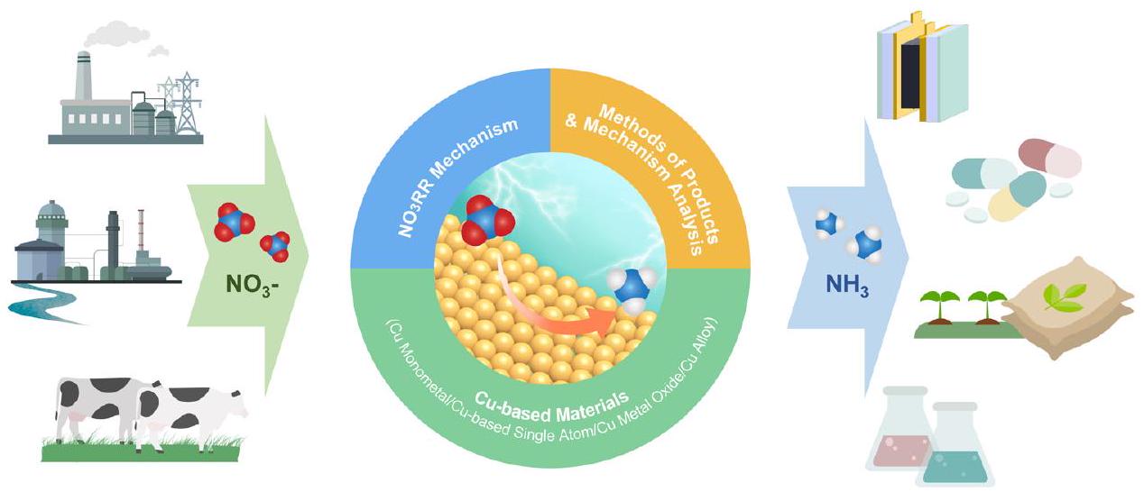
الشكل 1 توضيح تخطيطي لتفاعل اختزال النترات نحو تخليق الأمونيا.
آليات وطرق التقييم المقابلة لنوع مادة مميز. نظرًا للنمو الأسي في مخرجات البحث في هذا المجال، هناك حاجة ملحة لمراجعة شاملة ومحدثة تلخص التقدمات الأخيرة. تهدف هذه المراجعة إلى سد هذه الفجوة، وتقديم مورد قيم يوفر إرشادات ثاقبة للبحوث الجارية في هذا المجال من الدراسة. الهيكل الرئيسي لهذه المراجعة موضح أدناه (الشكل 1).
أولاً، آلية التفاعل لـيتم مناقشة ذلك من منظور مسارات التفاعل والوسطاء، ومعايير النشاط، ومعايير الانتقائية على المحفزات الكهربية القائمة على النحاس. بالإضافة إلى ذلك، سيتم توضيح التحديات الرئيسية لتقليل النترات من أجل إنتاج الأمونيا. ثانيًا، يتم تقديم أنواع مختلفة من المواد القائمة على النحاس لإنتاج الأمونيا الكهربية. ثالثًا، يتم تقديم طرق التحليل لإنتاج الأمونيا الكهربية المستخدمة في الكشف عن المنتج (الأمونيا)، وتوصيف الوسطاء التفاعليين والأنواع النشطة على سطح القطب. أخيرًا، يتم تطبيق المحفزات القائمة على النحاس في إنتاج الأمونيا الكهربية عبر والتحليل الاقتصادي المقابل مقدم. التحديات المتبقية في التنمية المستقبلية لـسيتم تسليط الضوء على ذلك وسيتم اقتراح آفاق مستقبلية.
2. رؤى حول الآلية الكهروتحفيزية
تطوير المحفزات الفعالة ذات النشاط والانتقائية الممتازة يعتمد بشكل كبير على الفهم العميق للآلية الكهروكيميائية. في هذا القسم، آلية التفاعل لـبما في ذلك مسارات التفاعل والوسطاء، والنشاط، ومعايير الانتقائية، خاصة للمواد القائمة على النحاس، سيتم وصفها بالتفصيل كإرشادات عملية لتصميم واختيار المحفزات الكهربائية.
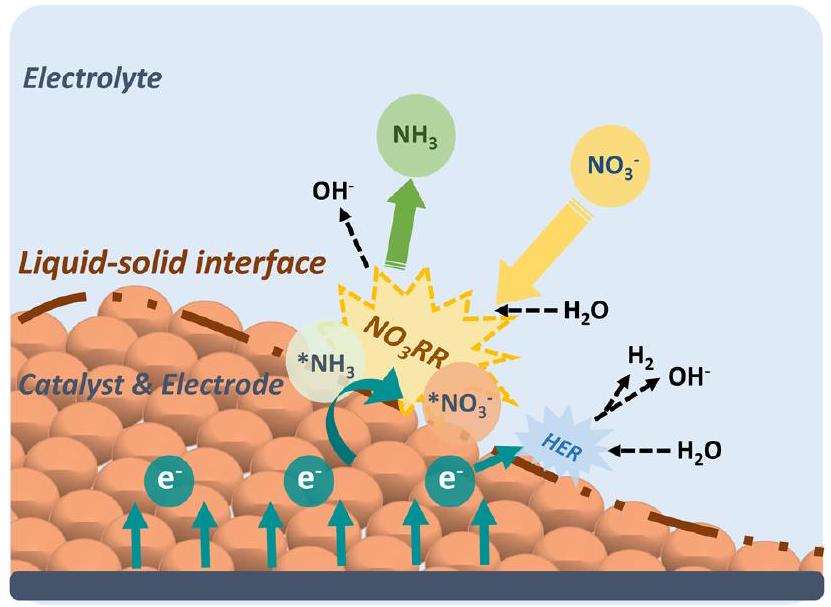
قبل الخوض في مسارات التفاعل والوسطاء لـنقاش عام حول آلية العمل لـيتم تقديمه على مقياس الكهروضوئية كما هو موضح في الشكل 2. أولاً، أيونات النترات () في الإلكتروليت تهاجر إلى سطح القطب، حيث تشكل نترات ممتصة ( ). ثم، الأيون يتحد مع جزيئات الماء والإلكترونات ويحدث عند واجهة السائل-الصلب، محولاًإلى الأمونيا الممتصة ( ). يتم توفير الإلكترونات، في هذه الحالة، بواسطة الدائرة الخارجية ويتم نقلها عبر القطب. بعد ذلك، يفصل من السطح، مدركًا التحويل من النترات إلى الأمونيا. بشكل عام، الـيتضمن سلسلة من خطوات إزالة الأكسجين من النترات إلى *NO (أو *N)، تليها خطوات هدرجة لإنتاج الأمونيا. في كل خطوة أساسية، يحدث نقل للهيدروجين بين مانحي الهيدروجين ( ) والمستقبلات (المادة الممتصة). ديناميكاتتأثر بشدة بطبيعة نقل الهيدروجين وكثافة مانحي الهيدروجين المتاحين. ومع ذلك، إذا كان إعادة دمج لتشكيلمن خلال مسار HER، يقلل من توفرللخطوات التالية منويمكن أن يحد من الكفاءة العامة لإنتاج الأمونيا.
الشكل 2 المخطط الذي يوضحمبدأ على مقياس الأقطاب.
لذلك، دراسة آليةهو في غاية الأهمية لأنه يوفر رؤى حول مسار التفاعل ويسمح بتحديد الاستراتيجيات لتنظيم العملية وتقليل تفاعل الهيدروجين المنافس. إن الفهم الشامل للخطوات الأساسية المعنية في، بما في ذلك خطوات إزالة الأكسجين والهيدروجين، يسمح للباحثين بتحديد العوامل الحاسمة التي تؤثر على حركية التفاعل والانتقائية. يمكن بعد ذلك استخدام هذه المعرفة لتصميم محفزات بخصائص مصممة أو تعديل ظروف التفاعل لتحسينمعالجة وتقليل حدوث HER.
2.1. مسارات التفاعل والوسطاء
مع نطاق واسع من حالات التكافؤ منإلى (تتراوح من +5 إلى -3)، تخضع تحويلات النيتروجين لعملية نقل معقدة تتضمن ثمانية إلكترونات تشمل سلسلة من الوسائط. في العملية الكاملة، تشمل الوسائط مثل إعلانات، وما إلى ذلك، متورطة بين النترات والأمونيا. لفهم الآلية بشكل أفضل، مسارات التفاعل والوسطاء لـيجب تحديده ضمن إطار الديناميكا الحرارية.يمكن تقديم عملية التفاعل العامة لتقليل النترات نحو الأمونيا في شكل معادلة كما هو موضح أدناه:
ملخص وانغ وآخرون أن هناك جزئين يشكلان مساراتالمسارات المسماة بالتقليل الكهربائي المباشر والتقليل الذاتي غير المباشر.في الاختزال الكهروكيميائي المباشر، تشارك النترات مباشرة في عملية نقل الإلكترون بينما تُسمى مسارات التفاعل التي لا تشارك فيها النترات في نقل الإلكترون مسارات الاختزال غير المباشرة. يعتمد حدوث أي من المسارين على تركيز النترات والبروتونات. عادةً، عندما يكون تركيز النترات في نطاق 1.0 م إلى 4.0 م وتحت ظروف حمضية شديدة، فإن ممتصسيتم بروتنة إلى حمض النيتروز ( )، مما يؤدي إلى آليتين ذاتي التحفيز تعرفان باسم مسار فيتر ومسار شميت. تشمل منتجات هذه المسارات أكسيد النيتروجين (NO) وثاني أكسيد النيتروجين (ثنائي أكسيد النيتروجين ) وحمض النيتروز لذا، فإن مسارات الاختزال الذاتي غير المباشرة غير مرغوب فيها عند السعي لإنتاج الأمونيا.
يتم تصنيف الآلية في مسارات الاختزال الكهروكيميائي المباشر إلى جزئين بناءً على الوساطة المختلفة للتفاعل، وهما اختزال الهيدروجين الممتص واختزال الإلكترون. بالنسبة لمسار اختزال الهيدروجين الممتص، يتم تنظيم التفاعل بواسطة ذرات الهيدروجين الممتصة.التي تتشكل من خلال الاختزال (عملية فولمر) على سطح الكاثود.ثم، تعمل *H على تقليل أيونات إلىمن خلال سلسلة من التفاعلات المتتالية التي تظهر في المعادلات التالية المقترحة من قبل شو وآخرون (المعادلات (2.2)-(2.9)):
مسار اختزال الإلكترون، حيث تتوسط الإلكترونات تفاعل اختزال النترات بالكامل، مقبول على نطاق واسع. في هذا المسار، يتم أولاً تحفيز النترات إلى نيتريت بواسطة الإلكترونات، ويحدث هذا التفاعل مباشرة على سطح القطب كما هو موضح في المعادلات أدناه (المعادلة (2.10) و (2.11)).
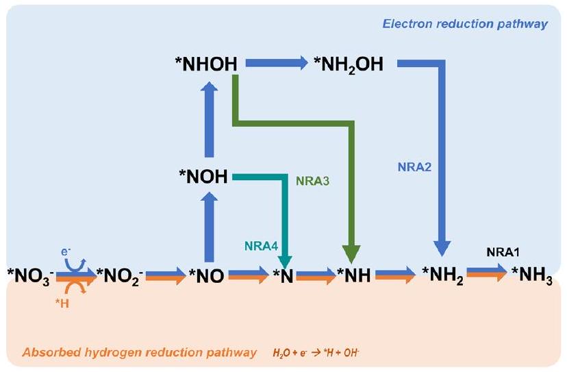
ومع ذلك، بالنسبة للعملية من النيتريت إلى الأمونيا، لدى الباحثين آراء مختلفة حول الوسائط والمسارات المحددة. بشكل عام، هناك ثلاث مسارات نموذجية لـتم اقتراح تحويل الأمونيا على سطح محفزات النحاس (المختصر بـ NRA). تتضمن الطريقة NRA1 كما هو موضح في الشكل 2 تكوين الأمونيا من خلال الوسيط *N، والذي يتماشى مع المعادلات المذكورة أعلاه التي اقترحها شيو وآخرون.في هذا المسار، يجدر بالذكر أن اثنين من *N قد يتحدان لإنتاجكما هو موضح في المعادلة (2.12):
ومع ذلك، فإن حاجز الهجرة لـأعلى بكثير من حاجز الهجرة لـ. بالإضافة إلى ذلك، أفاد جاو وآخرون أن تشكيل السندات أكثر ملاءمة من الروابط من منظور حركي، مؤشرًا على ميل قوي نحو الأمونيا بدلاً من النيتروجين (الشكل 3).
الشكل 3 المسارات المقترحة للاختزال الكهروكيميائي المباشر لتقليل النترات نحو الأمونيا.
مسار شائع آخر، يُسمى NRA2 ويظهر في الشكل 2، يتضمن الوسيط *NOH طوال التفاعل بأكمله.هناك خطوات إزالة الأكسجين مشابهة في هذين المسارين حتى تشكيل، والفرق الرئيسي بين هذين المسارين هو تسلسل التفاعل للهدرجة وإزالة الأكسجين. على الرغم من أن هذين المسارين قد تم الإبلاغ عنهما ومراجعتهما على نطاق واسع، فقد حدد هو وآخرون مسارًا أكثر ملاءمة حيث تحدث إزالة الأكسجين على *NHOH، مما يشكل *NH.تمت تسمية هذا المسار NRA3. في عمل هو، تم تقييم المسارات الثلاثة جميعها على سطح النحاس (111) المعرض بشكل شائع ومستقر من خلال حسابات نظرية الكثافة الوظيفية تحت الشرط المحدد لـتعتبر طاقات جيبس الحرة عاملاً حاسماً في تحديد تلقائية التفاعل والمراجع الرئيسية في تحديد مسارات التفاعل. أظهرت النتائج أنه على الرغم من أن NRA1 أكثر ملاءمة من حيث الديناميكا الحرارية، إلا أنها تظهر حركية بطيئة مع حاجز طاقة أعلى ناتج عن الطاقة التنشيطية العالية (1.62 إلكترون فولت) لـ *NO.وهو أعلى بمقدار 20 مرة من طاقة التنشيطمنعلاوة على ذلك، فإن طاقة التنشيطمنفي NRA2 أعلى بكثير من طاقة التنشيط (0.23 إلكترون فولت) لـ *NHOHفي NRA3. بالإضافة إلى ذلك، فإن الوسطاء في NRA2 يميلون إلى الانفصال بسهولة أكبر (مثل الهيدروكسيلامين)، مما يؤدي إلى تكوين المزيد من المنتجات الجانبية ويسبب آثارًا جانبية على الانتقائية. علاوة على ذلك، فإن طاقات غيبس الحرة لكل مسار تحتو 14 تعتبر أيضًا. مع أخذ كل هذه العوامل في الاعتبار، تم إثبات أن NRA3 هو المسار الأكثر احتمالًا فيعلى جميع نطاقات pH. مؤخرًا، أبلغ كراماد وآخرون عن مسار على Cu (111) مشابه لذلك في عمل هو.المسمى NRA4 في هذه المراجعة. ومع ذلك، هناك وسيطين مختلفين عن تلك الموجودة في مسار NRA3 السابق كما هو موضح في الشكل 2. بشكل خاص، تختلف الوسائط المعنية في إزالة الأكسدة من *NOH إلى *NH بين المسارين، حيث يتكون *N نتيجة اختزال *NO. على الرغم من الاختلافات الطفيفة في المسارات، تظل الخطوة المحددة المحتملة هي الهدرجة منإلى.
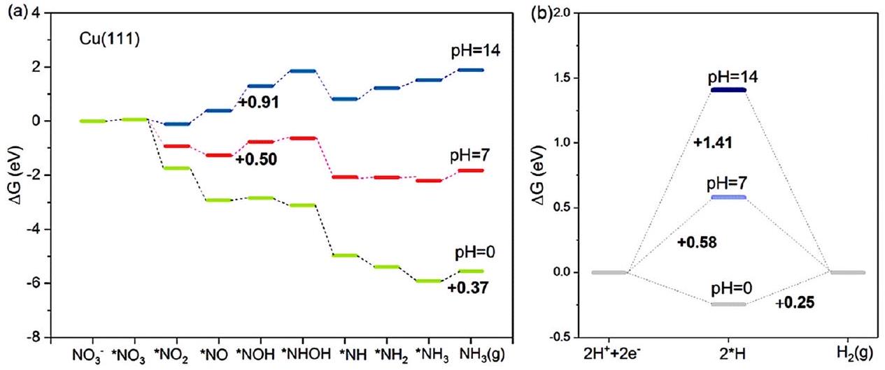
استنادًا إلى مسار NRA3، الذي يُعتبر المسار الأكثر ملاءمة، يتم تقييم تأثيرات الرقم الهيدروجيني على طاقات غيبس الحرة لسطح النحاس (111) الأكثر شيوعًا.كما هو موضح في
الشكل 4 المنافسة بين (أ) و (ب) HER على Cu (111) عند و 14، تم دراستها بواسطة هو وآخرون. أعيد طبعها بإذن من المرجع 33. حقوق الطبع والنشر 2021، الجمعية الكيميائية الأمريكية.
الشكل 4، عندالخطوة المحددة لمعدل التفاعل هي إزالة *، والتي تحتاج إلى 0.37 إلكترون فولت في NRA3. ومع ذلك، في ظل الظروف المحايدة لـتصبح خطوة تحديد المعدل هي عملية الهدرجة *لا *NOH بحاجز طاقة حرارية قدره 0.50 إلكترون فولت. عند تظل الخطوة المحددة لمعدل التفاعل تحدث خلال عملية الهدرجة هذه مع طاقة غيبس الحرة أعلى تبلغ 0.91 إلكترون فولت. تم التكهن من نتائج الحسابات،العملية أكثر ملاءمة من الناحية الطاقية عند مستويات أعلىتركيزات (قيم pH أقل). في الوقت نفسه، المنافسة بينو يُعتبر HER أيضًا تحت الظروف الثلاثة المذكورة أعلاه. تحت الظروف الحمضية، فإن الخطوة المحددة لمعدل HER هي تشكيل ( 0.25 إلكترون فولت)، حيث تكون طاقة غيبس أقل من تلك في، مما يوحي بالدونيةالأداء بسبب HER القوي. تحت الظروف المحايدة والقلوية، تكون الحالات مختلفة: الخطوة المحددة لمعدل HER هي، مع طاقات غيبس الحرة تبلغ 0.58 إلكترون فولت و 1.14 إلكترون فولت، على التوالي. كلا هذين القيمتين أعلى من القيم المقابلةمنالعملية، مما يدل على تحسين الانتقائية نحو الأمونيا مع تقليل تفاعل الهيدروجين. لتلخيص ذلك، عند تركيز أعلى منستكون حواجز الطاقة أقل لكلاوهي. ومع ذلك، من المهم أن نأخذ في الاعتبار العلاقة التنافسية بين هاتين التفاعلتين عند تحديد قيمة الرقم الهيدروجيني المثلى لـوبذلك يمكن تحقيق أقصى انتقائية لتخليق الأمونيا.
2.2. معايير النشاط
النشاط هو أمر ذو أهمية قصوى في تقييم محفز معين ويعمل كدليل قيم لتطوير محفز جديد. بشكل عام، بالنسبة لمحفز معين، يتم تحديد النشاط التحفيزي لتفاعل ما من خلال الجهد المطبق وقوة الامتزاز للوسطاء، مما يؤثر على تركيز كل من المتفاعلات والوسطاء. في الـ تؤثر طاقات الامتزاز لذرة النيتروجين وذرة الأكسجين بشكل مباشر على الأنشطة، بينما يتم التحكم أيضًا في العلاقة بين الحد الأقصى للنشاط وطاقات الامتزاز لمادة معينة بواسطة الجهد المطبق.
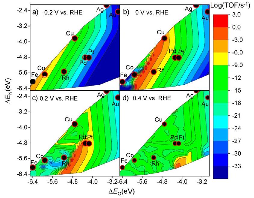
حقق ليو وآخرون في أنشطة المعادن الانتقالية المختلفة، و Pt) عند تطبيقات مختلفة إمكانات (“، و 0.4 فولت مقابل القطب الهيدروجيني القابل للعكس (RHE) من خلال نمذجة الميكروكينتيك المتوسطة الحاسوبية المستندة إلى نظرية الكثافة الوظيفية (DFT).كما هو موضح في الشكل 4، يتم بناء مخطط البركان النظري لترددات الدوران (TOF) كدالة لطاقة امتصاص الأكسجين والنيتروجين الذري. عند مقارنة الأنشطة القصوى بناءً على المحاكاة النظرية، فإن النحاس لديه أعلى نشاط فيبين المحفزات المعدنية غير النبيلة، وهو ما يتماشى مع التقرير السابق القائم على التجارب.حساب خطوات الجهد المحدد هو نهج آخر لتقدير الأنشطة التحفيزية للمعادن.كما أفاد كراماد وآخرون، فإن خطوة الجهد المحدد للنحاس هي *NO-*NOH مع الجهود المحددة المقابلة البالغة -0.23 فولت مقابل RHE. من خلال المقارنة، يمكن إثبات أن النحاس هو الأكثر نشاطًا بين المحفزات المعدنية غير الثمينة لـ.
2.3. معايير الانتقائية
الانتقائية هي عامل رئيسي آخر لا ينبغي تجاهله عند تصميم المحفزات الكهربائية الفعالة. كونه تفاعلًا له مسارات تفاعل معقدة، يمكن أن تتولد منتجات ثانوية متنوعة خلالعملية مثللا، إلخ.وبالمثل، فإن طاقات الامتزاز و ) والجهد المطبق له تأثيرات كبيرة على الانتقائية تجاه المنتجات.كما هو موضح في الشكل 5، بشكل عام، مع المزيد من الجهود السلبية،سيتم تعزيز الإنتاج، في حين أن المزيد من الإمكانيات الإيجابية ستعزز الانتقائية نحو، الذي يتماشى مع جهد القطب القياسي الأعلى ( مقابل RHE) في الإنتاج. في هذه الأثناء، تشكيليتطلب طاقات امتصاص قوية لكل من النيتروجين والأكسجين الذريين بينما يتشكليفضل الاعتدال النسبي و . وبالتالي، فإن النحاس لديه أفضل انتقائية تجاه الأمونيا في بين المعادن غير النبيلة (الشكل 6).
بصرف النظر عن تشكيل المنتجات الثانوية، فإن تفاعل اختزال الهيدروجين (HER) هو تفاعل تنافسي قوي ضدتحت الجهود السلبية. في هذا الصدد، تقييمالانتقائية تجاه HER هي معيار تقييم رئيسي. وقد تم الإبلاغ عن أن طاقة الربط لـهو وصف معقول لنشاط HER.لتوضيح مقالة مفتوحة الوصول. نُشرت في 05 فبراير 2024. تم تنزيلها في 14/1/2025 الساعة 6:59:24 صباحًا. (cc) BY-Nc هذه المقالة مرخصة بموجب رخصة المشاع الإبداعي النسب-غير التجاري 3.0 غير محمية.
الشكل 5 مخططات بركانية نظرية لـ TOF كدالة للأكسجين الذري ) والنيتروجين ( طاقات الامتزاز لتقليل النترات الكهروكيميائي على أسطح المعادن الانتقالية استنادًا إلى محاكاة الميكروكينتيك المعتمدة على DFT عند (أ) -0.2 فولت، (ب) 0 فولت، (ج) 0.2 فولت، و(د) 0.4 فولت مقابل RHE بواسطة ليو وآخرين. أعيد طبعها بإذن من المرجع 52. حقوق الطبع والنشر 2019، الجمعية الكيميائية الأمريكية.
الشكل 6 خرائط الانتقائية النظرية لـ، أو المنتجات الناتجة عن اختزال النترات الكهروكيميائي كدالة لطاقة امتصاص الأكسجين والنيتروجين عند (أ) -0.2 فولت، (ب) 0 فولت، (ج) 0.2 فولت، و(د) 0.4 فولت مقابل RHE بواسطة ليو وآخرين. أعيد طبعها بإذن من المرجع 52. حقوق الطبع والنشر 2019، الجمعية الكيميائية الأمريكية.
ميل الانتقائية نحو HER أوقام كرماد وآخرون بدراسة العلاقة بين الجهود المحددة لتفاعل الهيدروجين.على مجموعة متنوعة من المعادن الانتقالية.كما هو موضح في الشكل 7،يمثل الميل الانتقائي لـ فوقها، بينما يعكس اتجاه النشاط لـ. يبدو أن أكثر المحفزات فعالية تظهر في الزاوية العليا اليمنى من الشكل. في الختام، يُقترح أن يكون النحاس هو أكثر المحفزات المعدنية الانتقالية نشاطًا وانتقائية لـمما يجعل المواد القائمة على النحاس واعدة لتقليل النترات نحو الأمونيا.
الشكل 7 الفروق بين الجهود المحدودة لـو HER بواسطة Xu وآخرون. أعيد طبعها بإذن من المرجع 26. حقوق الطبع والنشر محفوظة لجمعية الكيمياء الملكية.
في الختام، مع الاهتمام الكبير بمحفزات الكهرباء القائمة على النحاس لـالعديد من الأعمال التي تحقق في آلية الرؤية في التحفيز بواسطة النحاس-تم الإبلاغ عنها من خلال الحسابات النظرية. مسارات مختلفة منتم اقتراحها دون الوصول إلى استنتاج نهائي على الرغم من أن المسار NRA3 الذي تم مناقشته سابقًا يعتبر أكثر ملاءمة بالنسبة للنحاس. بالإضافة إلى ذلك، تم إثبات النشاط والانتقائية للمواد القائمة على النحاس من منظور الآلية الأساسية.
3. المواد القائمة على النحاس
تفاعل واعد في إنتاج الأمونيا من خلال التحفيز الكهربائي. ومع ذلك، فإن المسارات الإلكترونية المعقدة لـيتطلب تحويل النيتروجين إلى الأمونيا وجود محفزات كهربائية نشطة للغاية وانتقائية لمواجهة التفاعلات المنافسة الأخرى، حيث يُعتبر تفاعل الهيدروجين (HER) هو الأكثر بروزًا. على مدار العقود القليلة الماضية، تم الإبلاغ عن مجموعة متنوعة من المحفزات الكهربائية التي تتمتع بأداء ممتاز في التخليق الكهربائي للأمونيا.من بينها، تعتبر المحفزات القائمة على المعادن الانتقالية، التي تمتلك التركيب الإلكتروني الفريد للأوربيتال d المملوء جزئيًا، قادرة على التبرع بالالكترونات وقبولها من جزيئات أخرى بسهولة، وبالتالي تحقيق الامتصاص القوي لذرات النيتروجين الغنية بالإلكترونات.في هذه الأثناء، تمتلك المحفزات القائمة على المعادن الانتقالية القدرة على تثبيط تفاعل الهيدروجين التنافسي وزيادة حواجز الطاقة للمنتجات الثانوية، مما يعزز الكفاءة.وانتقائية تجاه الأمونيا.علاوة على ذلك، تم إثبات أن نقل الإلكترون يمكن أن يتسارع بسبب المستويات الطاقية القريبة بين المدارات d المملوءة بشكل كبير (HOMOs) والأدنى الفارغة.-مدارات (LOMOs) من المحفزات القائمة على المعادن الانتقالية.استنادًا إلى هذه الاعتبارات، تم دراسة المحفزات الكهروكيميائية القائمة على المعادن الانتقالية بشكل مكثف وتقريرها كمحفزات واعدة لتخليق الأمونيا الكهروكيميائية.
تم تطوير أول محفز كهربائي للنترات يحتوي على النحاس في عام 1979 بواسطة بلتشير وبورابيدي.في هذا العمل، عمل القطب الكهربائي القرصي النحاسي كعامل حفاز في وسط حمضي من البيركلورات والكبريتات، مما يؤكد جدوى تقليل النترات إلى الأمونيا من خلال المسار الكهروكيميائي. ومع ذلك، في العقود القليلة التالية، تم الإبلاغ عن عدد محدود من الأعمال بسبب انخفاض الكفاءة (FE) وعائد الأمونيا، مما جعل هذه الطريقة لإنتاج الأمونيا تبدو بلا قيمة مقارنة بالطرق البيولوجية والصناعية.لم يكن حتى السنوات الأخيرة أن جذب مجال تخليق الأمونيا الكهروكيميائية اهتمام الباحثين مرة أخرى بسبب الطلب المتزايد على الأمونيا الخضراء بهدف تحقيق الحياد الكربوني. بالإضافة إلى ذلك، ومع التقدم الملحوظ في طرق تخليق وتوصيف المواد النانوية، تم الإبلاغ عن العديد من المحفزات الكهربية المصممة حديثًا منذ ذلك الحين.
حتى الآن، يوجد عدد كبير من المحفزات المعدنية النبيلة مثل الروثينيوم،، وغيرها من الهياكل/الأشكال الثنائية المعدن وغيرها من الهياكل الجديدة قد تم التحقيق فيها بشكل مكثف، مما يظهر أداءً مرضيًا، بما في ذلك انخفاض الجهد الزائد مما يعني استهلاكًا محدودًا للطاقة، وارتفاع في الكفاءة و معدل إنتاج الأمونيا.ومع ذلك، فإن التكلفة العالية والاحتياطيات المنخفضة من المعادن النبيلة تحد من إمكانياتها للتطبيقات الصناعية على نطاق واسع. ونتيجة لذلك، فإن المحفزات من المعادن الانتقالية غير النبيلة، التي لا تتمتع فقط بتكلفة منخفضة نسبيًا ومصادر وفيرة، ولكنها أيضًا تظهر نشاطًا قابلًا للمقارنة في التخليق الكهربائي للأمونيا، قد جذبت اهتمامًا كبيرًا من الباحثين.
من بين هذه المحفزات الخالية من المعادن النبيلة، تُعتبر المواد القائمة على النحاس والنحاس مرشحين واعدين لـوحتى تظهر انتقائية ونشاط أفضل من العديد من المحفزات المعدنية النبيلة، وهو ما تم إثباته من خلال التقييم الشامل لكل من النتائج التجريبية والتحليل النظري الحاسوبي.لتحقيق انتقائية المنتج المثالية وحركيات التفاعل، كان هناك اهتمام كبير في تطوير محفزات كهربائية متقدمة قائمة على النحاس لـمن خلال ضبط موقع النحاس النشط عبر استراتيجيات متنوعة مثل هندسة الوجوه البلورية، الضبط الإلكتروني والهندسي، التعديل بالسبائك والتشويش، واستراتيجيات انتشار الذرات الفردية.بالإضافة إلى ذلك، يتضمن تصميم المحفزات القائمة على النحاس اختيارًا دقيقًا وهندسة لمواد الدعم لتعزيز أدائها التحفيزي. ويشمل ذلك استخدام مواد محددة مواد الدعم ذات خصائص سطحية محددة، مسامية وتفاعلات إلكترونية مع أنواع النحاس.
في هذا القسم، سيتم تصنيف المواد القائمة على النحاس التي تعمل كعوامل كهربائية في تفاعل اختزال النترات لإنتاج الأمونيا وتقديمها بشكل فردي. تلخص الجدول أدناه أحدث الأداءات الكهروكيميائية للمواد القائمة على النحاس في الـ (الجدول 1).
3.1. مع المعدن الواحد
في عام 1979، تم استخدام قرص من النحاس ككاثود في وسط مائي حمضي من البيركلورات والكبريتات للمرة الأولى.كشفت التجارب أن أيونات النترات يمكن أن تُختزل في النهاية إلى الأمونيا إذا تم توفير بروتونات كافية في التفاعل. كما اقترح المؤلفون أن اختزال النترات حساس لظروف التفاعل، وخاصة مواد الأقطاب. على الرغم من أن طرق التجريب والتوصيف كانت ضعيفة نسبيًا مقارنة بالتكنولوجيا الحالية، إلا أن هذا العمل قدم إلهامًا كبيرًا للبحث الإضافي حول المحفزات الكهربية المعتمدة على النحاس في ذلك الوقت.
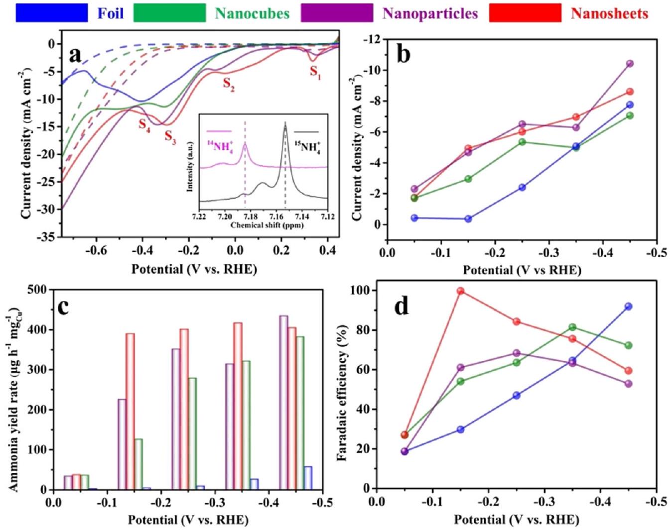
نظرًا للتطور السريع في تكنولوجيا النانو، فقد أدت المواد أحادية المعدن إلى ظهور العديد من المحفزات ذات البنية الدقيقة. عندما يتم تقليل النحاس إلى مقياس النانو في اتجاه واحد أو عدة اتجاهات، فإن حركة الإلكترونات في هذا الاتجاه تخضع للاحتجاز، مما يؤدي إلى انتقال في خصائص المادة ويؤثر بشكل عميق على الأداء التحفيزي.على سبيل المثال، أبلغ فو وآخرون عن محفز من نانوورقة النحاس لتقليل النترات إلى الأمونيا مع انتقائية عالية جدًا للأمونيا.وصلت القيمة القياسية لـ FE إلى عند -0.15 فولت مقابل RHE، مع معدل إنتاج الأمونيا “، والذي كان أعلى بأكثر من 400 مرة من ورق النحاس السائب. يمكن أن يُعزى الأداء المتميز إلى تقليل تفاعل الهيدروجين (HER) وزيادة كثافة التيار للخطوة المحددة بمعدل التفاعل، وهي توليد النيتريت ( ) في هذه التفاعل. من الجدير بالذكر أن المؤلفين قاموا بتحليل قمم الاختزال المعروضة على منحنيات LSV المتعلقة بأربعة عمليات تفاعل مختلفة ( ، و ) كما هو موضح في الشكل 8.
الجدول 1 الأداء الكهربائي الكيميائي للمواد القائمة على النحاس في
نوع المادة
اسم
إمكانات
نسبة الكفاءة (%)
عائد
إلكتروليت
مرجع
معادن أحادية
قرص
-0.55 فولت مقابل SCE
68
غير متوفر
و
65
ورقة نانوية من النحاس
-0.15 فولت مقابل RHE
99.7
0.1 م كوه
82
قرص نانو نحاسي
-0.5 فولت مقابل RHE
81.1
0.1 م كوه
85
ذرة واحدة من النحاس
-0.64 فولت مقابل RHE
65.3
و
86
سَاك
-1.0 فولت مقابل RHE
84.7
0.1 م كوه
87
-1.5 فولت مقابل SCE
94
و
٨٨
أكسيد النحاس
نيوزيلندا الغربية
-1.2 فولت مقابل SCE
78.57
و
٤٨
-0.8 فولت مقابل RHE
92.28
غير متوفر
و
89
(100) وجه
-0.6 فولت مقابل RHE
82.3
و
90
-1.1 فولت مقابل
٨٩.٥٤
و
91
سبائك النحاس
شمال غرب
-0.13 فولت مقابل RHE )
90
1.0 م كوه
77
أوراق نانوية من النحاس والكوبالت
-0.2 فولت مقابل RHE )
100
1.0 م كوه
92
(111)
-0.2 فولت مقابل RHE
97
0.1 م كوه
93
-0.7 فولت مقابل RHE
94.5
و
94
-0.15 فولت مقابل RHE
99
غير متوفر
1.0 م كوه
74
Rh@Cu
-0.2 فولت مقابل RHE
93
و
83
-0.75 فولت مقابل RHE
81.34
و
95
الشكل 8 الاختزال الكهربائي للنترات إلى الأمونيا على محفز النحاس. (أ) منحنيات الفولتمترية المسحية الخطية لمحفزات النحاس على ورق الكربون المقاسة في 0.1 م كOH (الخط المنقط) في وجود (خط صلب). معدل المسح: . (ب) كثافات التيار، (ج) معدلات إنتاج الأمونيا و(د) كفاءات فاراداي لمختلف محفزات النحاس لإنتاج الأمونيا عند إمكانيات مطبقة مختلفة. تم إعادة طباعته بإذن من المرجع 76. حقوق الطبع والنشر 2020 لشركة إلسفير المحدودة.
: تنافس الامتزاز ( ) من الأنواع المتوسطة N – تعديل السطح البلوري للعوامل الحفازة هو استراتيجية فعالة لتحسين الخصائص الحفازة الجوهرية. تم الإبلاغ عن التخليق السهل لأقراص نانوية موحدة من النحاس مع جوانب مكشوفة من Cu (111)، والتي تعمل كعامل حفاز عالي النشاط لإنتاج الأمونيا، من قبل وو وآخرون.باستخدام غاز الأكسجين المؤكسد والجلوكوز المختزل، تم تصنيع أقراص النحاس النانوية، التي يبلغ سمكها 7 نانومتر وقطرها 80 نانومتر، من خلال تفاعل استمر ثلاثة أيام. على الرغم من أن سطح أقراص النحاس النانوية كان مؤكسدًا جزئيًا، إلا أن الغالبية العظمى من المحفزات ظلت في حالة معدنية. خلال عملية اختزال النترات، تم أيضًا إزالة الأكسدة من السطح المؤكسد جزئيًا، مما أعاد بناء الوجه. في هذا العمل، 0.1 م KOH، 0.1 م KOH مع و 0.1 م KOH مع 10 م م تم اختيارها كمرجع، على التوالي. وُجد أن
أن أقراص النحاس النانوية تظهر امتصاصًا أفضل للنترات مقارنة بالنترات من جهد التفوق لخصائص LSV. كانت انتقائية للأمونيا وصلت إلى ذروتها مع أقصى FE من عند -0.5 فولت مقابل RHE وأقصى معدل إنتاج للأمونيا من عند -0.63 فولت مقابل RHE، على التوالي.
كان من الجدير بالذكر أن معدل إنتاج الأمونيا تم تأكيده باستخدام كل من طيف الرنين المغناطيسي النووي (NMR) وطريقة إندوفينول الزرقاء العادية من خلال مطيافية الأشعة فوق البنفسجية-المرئية (UV-vis)، مما يحسن موثوقية البيانات. سيتم تقديم تفاصيل الطرق في الأقسام اللاحقة. نظرًا لأن Cu (111) تم إعادة بنائه من حالة أكسدة النحاس، تمت مقارنة سطح Cu (111) المثالي مع سطح Cu (111) المعاد بناؤه في دراسة آليات التحفيز من خلال حسابات DFT. يمكن الاستنتاج أن تجمعات النحاس الثلاثية الذرات التي تشكلت في إعادة البناء ضعفت من تفاعل الروابط وأظهرت امتصاصًا أفضل لـ ، مما يحسن الأداء إلى معيار عملي. بالإضافة إلى ذلك، عندما يتم تقليل حجم النحاس إلى الحد الأدنى، يمكن تقليله إلى الشكل النهائي للجزيئات النانوية – ذرات النحاس الفردية، التي تظهر هياكل إلكترونية فريدة تعظم استخدام الذرات. سيتم تناول المناقشة المحددة حول هذا النوع من المحفزات الكهربائية في قسم لاحق.
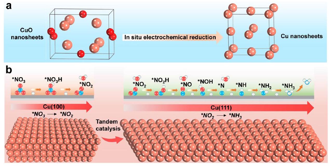
الشكل 9 توضيح تخطيطي لتعزيز التحليل الكهربائي عبر صفائح النحاس النانوية من خلال التحفيز المتسلسل. (أ) الاختزال الكهربائي في الموقع لصفائح CuO النانوية المحضرة أثناء . (ب) التفاعل المتسلسل لـ و الوجوه. أعيد طبعها بإذن من المرجع 100. حقوق الطبع والنشر 2023 وايلي-فيتش فيرلاخ GmbH.
علاوة على ذلك، استكشفت الدراسات الحديثة أيضًا التحفيز المتسلسل للوجه باستخدام محفزات النحاس أحادية المعدن. من خلال تعديل وجهي Cu (100) و Cu (111)، تم إنشاء نظام تحفيز متسلسل (الشكل 9)، حيث يتم توليد النترات على الوجه ثم يتم هدرجة على الوجه . يتم تحقيق آلية التحفيز المتسلسل هذه من خلال هندسة وجه البلورة وقد أظهرت أداءً عاليًا بمعدل إنتاج الأمونيا من عند -0.59 فولت مقابل RHE، وثبات ممتاز على مدى 700 ساعة.
3.2. ذرات النحاس الفردية
على الرغم من أن محفزات النحاس المعدنية الكتلية قد تم التحقيق فيها على نطاق واسع في تفاعل اختزال النترات لإنتاج الأمونيا، إلا أنها لا تزال تعاني من انخفاض الاستقرار والنشاط، خاصة بعد التشغيل لفترة طويلة. وفقًا للأبحاث السابقة، هناك مشكلتان تتعلقان بهذا الأداء غير المرضي، وهما تعطيل المحفز الناتج عن التآكل وتسمم النترات. للتغلب على هذه القيود، فإن تقليل حجم جزيئات النحاس النانوية إلى مستوى ذرة واحدة هو استراتيجية واعدة لتحفيز النحاس القائم على . توفر المحفزات أحادية الذرة مزايا بارزة من حيث كفاءة الاستخدام العالية للغاية والأداء التحفيزي الفريد مقارنة بموادها الكتلية. بشكل محدد، تم إدراج عدة نقاط بارزة تعزى إلى هذه المزايا أدناه: (1) المواقع النشطة المعرضة بشكل كافٍ تسهل الالتصاق القوي وتحويل المتفاعلات، مما يؤدي إلى نشاط أفضل؛ (2) المواقع والهياكل النشطة المتجانسة تسمح بتفاعل موحد بين المواقع النشطة والركائز، مما يؤدي إلى انتقائية أفضل؛ و (3) التفاعلات القوية بين الذرات الفردية وذرات التنسيق تثبت الذرات المعدنية الفردية، مما يؤدي إلى استقرار أفضل. وبالتالي، فإن استخدام الذرات الفردية كمحفزات كان جبهة جديدة في مجال التحفيز الكهربائي وقد أبلغت عدة أعمال عن محفزات النحاس أحادية الذرة لإنتاج الأمونيا من خلال
على سبيل المثال، أبلغ زو وآخرون عن محفز معدني-نيتروجين-كربون (M-N-C) مع ذرات النحاس الفردية المدفونة في
ورقة الكربون النيتروجينية ( )، مما يظهر نشاطًا استثنائيًا، وانتقائية، وثباتًا في تفاعل اختزال النترات. تم تصنيع المحفز أحادي الذرة من خلال التحلل الحراري لـ Cu-MOFs كمقدمة في جو من الأرجون. كما تم دراسة تأثير درجة حرارة التلدين على حجم جزيئات/ذرات النحاس على الورقة النانوية، مما يكشف أن زيادة درجة الحرارة أدت إلى تجمع ذرات النحاس. ومن الجدير بالذكر أنه عندما كانت درجة حرارة التلدين أقل من ، لم تكن ذرات النحاس مكشوفة، بل كانت مغطاة بطبقة سميكة من الكربون. تم تأكيد تشكيل ذرات النحاس الفردية عند من خلال صور المجهر الإلكتروني الناقل الماسح عالي الزاوية (HAADF-STEM) و XRD و هيكل الامتصاص القريب من حافة الأشعة السينية (XANES) وهيكل الامتصاص الدقيق الممتد للأشعة السينية (EXAFS). في هذا المحفز، وُجد النحاس في شكل و II بسبب تشكيل و لم يُلاحظ حتى تشكيل جزيئات النحاس النانوية، كما هو موضح في الشكل 8. كعامل حاسم لتطوير المحفزات الكهربائية، تم توضيح الاستقرار البارز لـ المحفز أحادي الذرة. مقارنةً بـ جزيئات نانوية (درجة حرارة التحلل الحراري لـ )، حافظت على أداء تحفيزي كهربائي متفوق مع انخفاض فقط بـ بعد 20 دورة متتالية. علاوة على ذلك، من خلال كل من الطرق التجريبية والحسابات النظرية، تم إثبات أن المحفز أحادي الذرة يخفف من إنتاج النترات وتراكمها مقارنةً بمحفزات النحاس الكتلية الأخرى، مما يعالج قضية حاسمة للمحفزات القائمة على النحاس في .
كما أبلغ يانغ وآخرون عن لاختزال النترات إلى الأمونيا بكفاءة فاراداي عالية تبلغ عند -1.00 فولت (مقابل RHE) ومعدل إنتاج أمونيا من كان المحفز المصنع يتميز بهيكل مسامي و مساحة سطح محددة كبيرة تبلغ . في ، تم تحديد تركيز النحاس ليكون ، ومحتوى النيتروجين كان . كما كشف المؤلفون عن آلية أخرى لـ ، حيث ستعيد ذرات النحاس الفردية تشكيلها إلى جزيئات نانوية أثناء عملية الاختزال الكهربائي.
عملية. كانت حالة التأكسد لـ SAC هي في شكل . ومع ذلك، في عملية تفاعل اختزال النترات، تم أيضًا تقليل وتجمع إلى النحاس المعدني، والذي يمكن اكتشافه في صور HAADF-STEM. بعد التحليل الكهربائي، سيتفكك تجمع الجزيئات النانوية بشكل عكسي ويتم تخزينه في هيكل مرة أخرى بعد إعادة الأكسدة في الهواء. بالإضافة إلى ذلك، تم تطبيق XAS operando وحسابات نظرية الكثافة أيضًا في الدراسة لكشف التطور الديناميكي لهيكل .
مؤخراً، كشف لي وآخرون بشكل منهجي عن تأثير الحجم للمحفز القائم على النحاس في بهدف دراسة تأثيرات الحجم، قام المؤلفون بتخصيص المحفز القائم على النحاس من المحفزات أحادية الذرة إلى المحفزات أحادية الكتلة والجزيئات النانوية. كشفت الدراسة عن تأثير الحجم وبيئة التنسيق على النشاط التحفيزي العالي والانتقائية لـ واقترحت استراتيجية تصميم واعدة للمحفزات القائمة على الهلام الهوائي ذات التحكم في الحجم لمختلف التفاعلات التحفيزية الكهربائية.
3.3. أكسيد النحاس المعدني
تعتبر أكاسيد المعادن فئة رئيسية أخرى من المحفزات المعدنية ذات أشكال سطحية وتركيبات متنوعة. تحتل أكاسيد المعادن الانتقالية مكانة مهمة في مجال التحفيز وتساهم في نشاط تحفيزي مرتفع نسبيًا. من بينها، ثبت أن أكاسيد النحاس المعدنية هي واحدة من أكثر المحفزات فعالية لإنتاج الأمونيا الكهربائية.
بالإضافة إلى التكوين المباشر لأكاسيد النحاس المعدنية خلال عملية التخليق، قد تخضع المواد القائمة على النحاس لتغيرات في الطور خلال عملية التحفيز الكهربائي، مما يؤدي إلى تشكيل أكاسيد النحاس المعدنية ذات أسطح وتركيبات مختلفة، مما ينتج عنه خصائص تحفيزية مختلفة. وبالتالي، قد لا تكون المواقع النشطة الحقيقية في التفاعلات الكهربائية هي الأنواع الأصلية على أسطح الأقطاب الكهربائية وتكون الدراسات التوصيفية في الموقع مطلوبة في البحث.
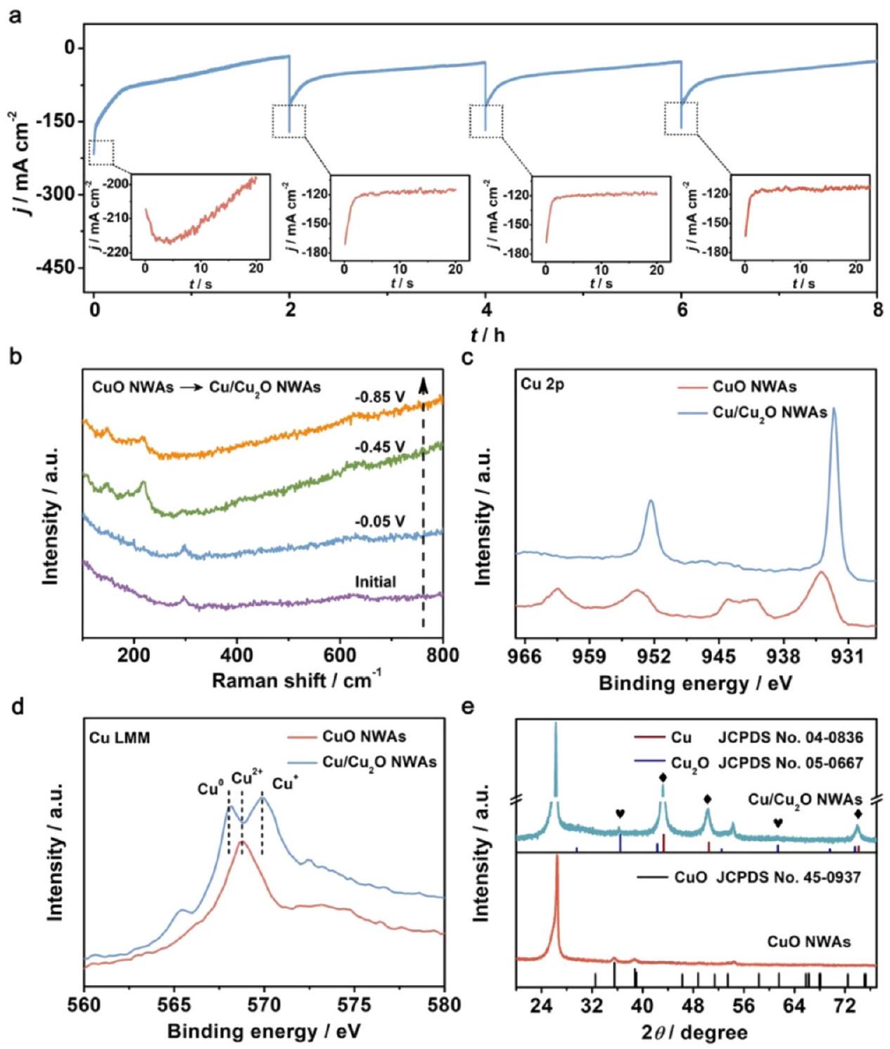
عادةً ما يُعتبر هو المواقع النشطة الحقيقية لاختزال النترات إلى الأمونيا. كشف وانغ وآخرون عن أصل انتقائية اختزال النترات إلى الأمونيا على المحفزات الكهربائية القائمة على النحاس. تم تصنيع وتقرير مصفوفات أسلاك النحاس النانوية مع FE استثنائي يبلغ عند -0.85 فولت في مع 200 جزء في المليون فقط من N -النترات. كانت إجراءات تخليق هذه المصفوفة النانوية القائمة على النحاس فعالة من الناحية التحفيزية بسيطة جدًا من خلال النمو في الموقع والمعالجة الحرارية على NWAs تحت جو من الأكسجين في . من خلال طيف رامان الكهروكيميائي في الموقع المدمج مع نمط XRD وطيف AES (طيف الإلكترون أوغر) كما هو موضح في الشكل 10، تم تأكيد إعادة البناء الكهروكيميائي خلال عملية التفاعل. في هذه العملية، تم تحويل CuO NWAs إلىالـ NWAs من خلال الاختزال في الموقع. اقترح المؤلف أن تشكيلعززت نقل الإلكترون عند الواجهة، وهو ما تم إثباته بشكل أكبر في حسابات DFT. يمكن أن تساعد الطريقة الكهروكيميائية أيضًا في توضيح العملية؛ حيث أظهرت أنابيب CuO بدون تقليل مسبق زيادة في كثافة التيار، وهو ما يمكن أن يُعزى إلى تقليل CuO. أيضًا، مقارنةً بالنحاس العاري، فإن الإلكترون الإضافي يمكن ملاحظة الكثافة من خلال النموذج النظري. كما تم حساب حاجز الطاقة لتطور الهيدروجين.أظهرت NWAs (0.33 eV) حاجز طاقة تفاعل أعلى بكثير من Cu NWs (0.12 eV)، مما يشير إلى تأثير مثبط ونشاط منخفض تجاه HER. في الختام، تم استنتاج أن الكثافة العالية للإلكترونات أدت إلى انخفاض حاجز التفاعل الذي أعاق HER التنافسي، مما أدى إلى تحويل عالي، وكفاءة عالية، وانتقائية.في اختزال النترات من أجل الأمونيا.
حقق كوين وآخرون في آلية اختزال النترات إلى الأمونيا على أسطح مختلفة مكشوفة من أكاسيد النحاس. اثنان من الأسطح المكشوفة لـوهو، و تمت دراستها. وجد المؤلفون أنحقق انتقائية ونشاط أعلى مقارنة بـ (111) بسبب انخفاض طاقة الحاجز. تم اعتبار التغير في الخصائص الإلكترونية هو السبب وراء الاختلاف وتم التحقيق فيه من خلال الحسابات النظرية. قام رين وآخرون بتصنيع سطح مقعر محدب.طبقة على أسلاك النحاس النانوية.في هذا المادة الكهربائية، حسّن النحاس المعدني الداخلي قدرة النقل الإلكتروني بينما الخارجي الطبقة وفرت المزيد من المواقع النشطة لتقليل النترات على أسطح الأقطاب. بالإضافة إلى ذلك، أثرت الواجهة على تعديل مركز حزمة النحاس d، مما أدى إلى ضبط طاقات الامتصاص لمختلف الوسائط في العملية. أعلى عائد من الأمونيا لـ تم تحقيقه تحت -1.2 فولت مقابل إلكترود الكالوميل المشبع في محلول محايد.
يعتبر المعدن السطحي عادةً الموقع النشط في التفاعلات الكهروكيميائية. وبالتالي، تم الإبلاغ على نطاق واسع في الأعمال الأخيرة عن الأنواع الأنيونية بما في ذلك فراغات الأكسجين، ومجموعات الهيدروكسيل، وتطعيم الأنيونات، وما إلى ذلك، بأنها مفيدة في تعزيز نشاط المحفزات.بالنسبة لمحفزات أكسيد النحاس، فإن إنشاء فراغات أكسجين باستخدام معالجة البلازما هو طريقة فعالة لتحسين النشاط الكهروكيميائي.إلى الأمونيا.تقنية إشعاع الليزر هي استراتيجية فعالة لإنشاء فراغات الأكسجين.قام جينغ وآخرون باستخدام إشعاع الليزر في تصنيع المواد الغنية بفجوات الأكسجينجزيئات النانو التي حققت في النهاية معدل إنتاج كبير من الأمونيامع FE منعند -0.25 فولت مقابل RHE.بالإضافة إلى ذلك، أفاد غونغ وآخرون بتعزيز الفجوات الأكسجينية ومجموعات الهيدروكسيل على السطح منبعد معالجة البلازما، مما يسهل امتصاص النترات ونقل البروتون بشكل أفضل. وقد ساهم ذلك في تعزيز الانتقائية بشكل كبير، مما أدى إلى تحقيق انتقائية استثنائية تصل إلىو FE الوصول تجاه الأمونيا. تم دراسة تأثير وقت معالجة البلازما بشكل أعمق، حيث أظهرت النتائج أن هيدروكسلة سطح المادة بلغت ذروتها عند معالجة لمدة 40 دقيقة، بينما أدى زيادة وقت المعالجة إلى فقدان مجموعات الهيدروكسيل من السطح.
3.4. سبيكة قائمة على النحاس
بالمقارنة مع المحفزات المعدنية الفردية، يمكن أن تعدل المحفزات المعدنية السبيكية توزيع الشحنة على المحفز من خلال إدخال معادن أخرى.من ناحية، فإن التباين داخل الجسيمات وبينها يؤدي إلى ظهور مواقع نشطة وأشكال مختلفة للجسيمات.في اختزال النترات
الشكل 10 (أ) منحنيات CuO NWAs خلال أربع دورات متتالية من عمليات NRA عند -0.85 فولت. المربعات الصغيرة: تفاصيل مكبرة في المربع المنقط. (ب) طيف رامان الكهروكيميائي في الموقع لـ CuO NWAs تحت إمكانيات معينة. (ج) طيف XPS لـ Cu 2 p لـ CuO NWAs و NWAs. (د) طيف LMM AES للنحاس و (هـ) أنماط XRD لـ CuO NWAs و NWAs. أعيد طبعها بإذن من المرجع 50. حقوق الطبع والنشر 2020 وايلي-فيتش فيرلاج GmbH & Co. KGaA، فاينهايم.
يمكن أن تقدم المعادن الإضافية خصائصها الجوهرية، مثل تثبيط إنتاج النيتريت أو تشكيل آليات تفاعل متسلسلة، مما يحسن الأداء الكهروكيميائي للمحفز.من ناحية أخرى، اعتقد بعض الباحثين أن سبائك النحاس يمكن أن تعزز المقاومة للتآكل بشكل كبير وتحسن الاستقرار على المدى الطويل مقارنةً بمحفزات النحاس أحادية المعدن.إن دمج النحاس (Cu) مع معدن ذو كهرسلبية أقل يمكن أن يخفف من الأكسدة، مما يقللالتشكيل. تعزز هذه الاستراتيجية مقاومة التآكل للسبائك المعتمدة على النحاس، حيث أن قدرة المعدن الثانوي على التبرع بالإلكترونات تقلل من احتمال أكسدة النحاس. بالإضافة إلى ذلك، فإن تشكيل الهتروذرات الروابط ذات الطاقة العالية للتفكك تعيق بشكل أكبر ذوبان النحاس. تعزز هذه الاستراتيجيات بشكل مشترك مقاومة التآكل لـ
سبائك النحاس، التي تحسن بشكل كبير من الاستقرار على المدى الطويل لمحفزات الكهرباء القائمة على النحاس، مما يجعلها مناسبة للبيئات القاسية والاستخدام الممتد.
أبلغ غوو وآخرون عن بلورات نانوية من النحاس والحديد تشبه الميتاسيكويا كعامل تحفيز كهربائي عالي الأداء لـأدى تشبع الحديد إلى تعميق مستوى الطاقة لـالنطاق وتعديل طاقة الامتزاز للوسطاء التفاعليين بشكل إيجابي، مما أدى إلى تحسين النشاط مع كفاءة عالية وانتقائية. قدم سارجنت وآخرون النيكل لتشكيل نظام سبيكة النحاس والنيكل حيث تم تعديل مركز النطاق d للنحاس، وتم تعديل طاقة الامتزاز للوسطاء. تم إثبات التحول الإيجابي لمركز النطاق d من خلال دمج نتائج UPS وXPS. كما تم تأكيد الآلية بشكل أكبر من خلال دراسات DFT. بالمقارنة مع النحاس النقي، تم تعديلحقق المحفز السبيكي زيادة بمقدار ستة أضعاف في نشاط في الإلكتروليت الذي يتكون من 1 م كوه و 100 مللي مقام جاو وآخرون بخلط النحاس مع الروثينيوم وصنعوا محفزات سبائك الروثينيوم-نحاس المدعومة بأكسيد الجرافين المخفض. ) للتوجيه المباشر النشاط الفعال لـيمكن أن يُعزى ذلك إلى التأثير التآزري بين مواقع الروثينيوم والنحاس من خلال التحفيز بالتتابع، حيث يظهر النحاس نشاطًا فعالًا في اختزالإلىبينما تظهر رو نشاطًا ممتازًا في تقليلإلى. بالإضافة إلى ذلك، يمكن أن يؤدي تخدير الروديوم بالنحاس إلى تعديل مركز حزمة d في السبيكة وتنظيم طاقات الامتزاز بشكل فعالإلىوبذلك تعزيز أداء إنتاج الأمونيا.
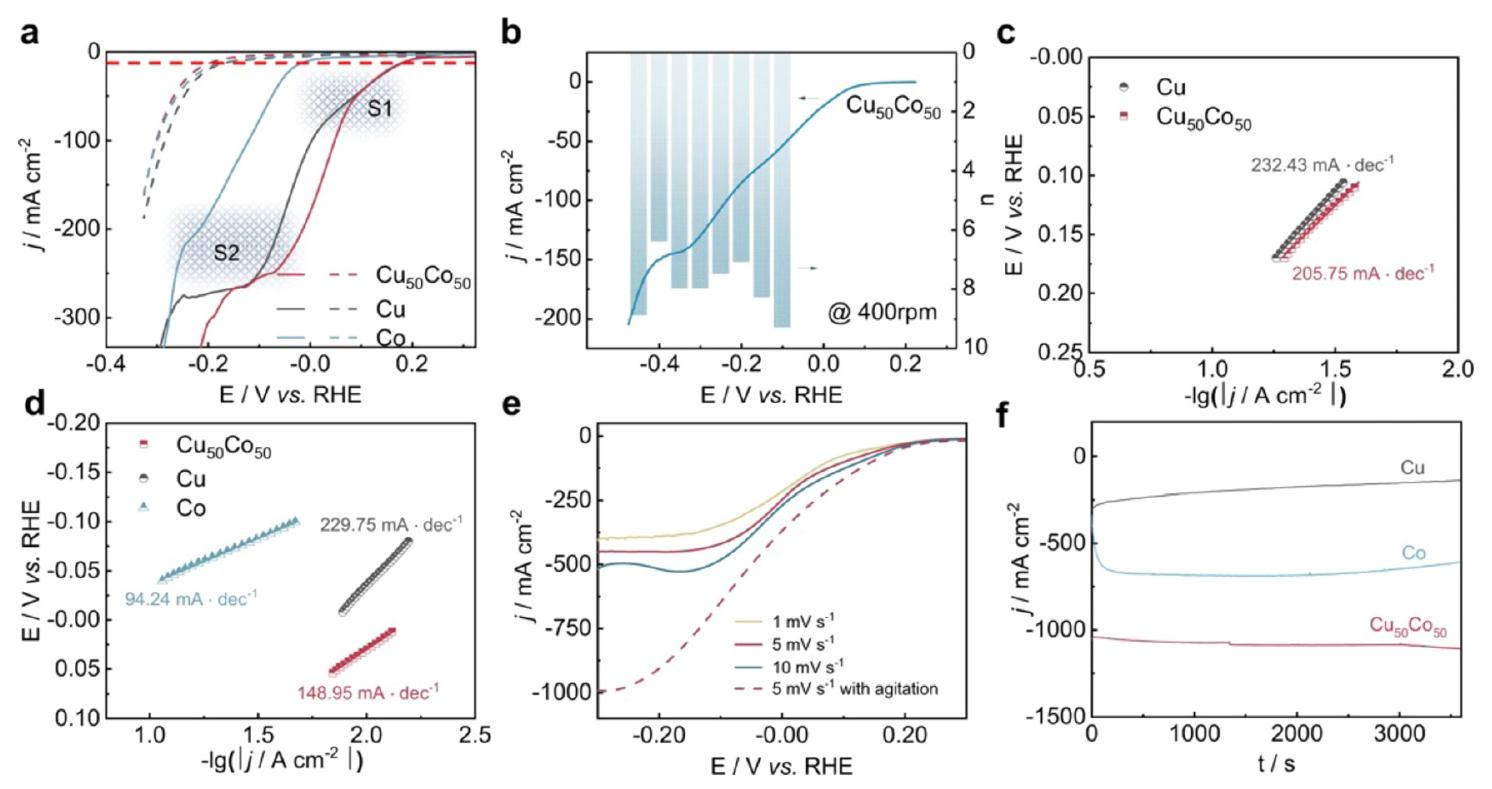
سبائك CuCo هي واحدة من أكثر أنواع المحفزات الكهربائية التي تم الإبلاغ عنها على نطاق واسع لـلهذاالمحفز الثنائي، اقترح هي وآخرون أيضًا آلية تحفيز متسلسلة.على وجه التحديد، كان النحاس هو الموقع النشط المثالي للارتباطوتحفيزإلىبينما كان الكوبالت انتقائيًا للغاية تجاه تحويلإلىاستنادًا إلى الأبحاث السابقة، أبلغ فانغ وزملاؤه عن محفز ثنائي المعدن من النحاس والكوبالت يتمتع بنشاط ممتاز وانتقائية لتقليل النترات إلى الأمونيا.عند -0.2 فولت مقابل RHE، قدمت ورقة النحاس والكوبالت FE منتحت كثافة تيار صناعي قدرها 1035 مللي أمبيرتحت ظروف قلوية (1 م كOH مع )، تمثل الأداء القياسي العالمي لـ حتى الآن. أدى إضافة الكوبالت إلى النحاس إلى معدل نقل إلكترونات سريع، كما هو موضح في أعداد نقل الإلكترونات وانحدارات تافل (الشكل 11)، مما يوفر الإلكترونات وبروتونات الهيدروجين للأنواع القريبة من النحاس بكفاءة ويعزز استخدام النترات. تم تطبيق مطيافية الأشعة تحت الحمراء المحولة فورييه (FTIR) في الموقع وSHINERS في الموقع المرتبطة بحسابات DFT لتوضيح آلية تأثير التآزر بين النحاس والكوبالت.
وبالمثل، أفاد فو وآخرون بأنهم دعموا أنفسهمالرغوة كوسيلة فعالةمحفزمن خلال إنشاء حقل كهربائي عند الواجهة بين رغوة النحاس و CoO، يتم تعزيز نقل الإلكترونات من النحاس إلى CoO، مما يؤدي إلى شحنة إيجابية على النحاس، والتي تعزز بدورها امتصاص أيونات النترات. هذه الآلية حسنت بشكل كبير الانتقائية للأمونيا، حيث وصلت إلى كفاءة فاراداي منمع أعلى معدل لإنتاج الأمونيا, والتي تتجاوز بكثير أداء رغوة النحاس الفارغة ورغوة CoO على رغوة النيكل. مؤخرًا، أبلغ ليو وآخرون أيضًا عن مصفوفات أسلاك نانوية ذات بنية نواة-قشرة (CuO NWAs@ ) من أجل يتم تخليق بنية النحاس-الكوبالت من خلال طريقة بسيطة من خطوتين تشمل النمو في الموقع لـ NWAs والنمو في الموقع لـ الكتل. وقد أدى ذلك إلى معدل عائد عالي للأمونيا قدره جنبًا إلى جنب مع كفاءة فاراداي قدرها . ينسب المؤلفون النشاط المعزز إلى التأثير التآزري للمراحل النشطة وتحسين امتصاص الهيدروجين الذري. بناءً على الآراء المذكورة أعلاه، على الرغم من أن الآليات المحددة قد تختلف بين هذه الأعمال، إلا أنها جميعًا تسلط الضوء على إمكانية استخدام النحاس والكوبالت معًا لتحسين الأداء التحفيزي.
مؤخراً، كانت هناك بعض الأعمال التي تقارن بين سبائك النحاس المختلفة من منظورين، نظري وتجريبي. درس زينغ وآخرون سلسلة من المحفزات ثنائية الذرات القائمة على النحاس (CuTM/g-CN، TM = Fe، Co، Ni، Zn، و Mn ) باستخدام رؤى نظرية.ركز زهاو وآخرون على المقارنة الأفقية بين سبائك المختلفة (المختصرة بـ CuM)، بما في ذلك CuCo و CuFe و CuNi على الكربون المسامي المنظم (المختصر بـ OMC).تم تخليق سلسلة CuM/OMC من خلال
الشكل 11 الأداء الكهروكيميائي لـ على ، النحاس النقي، والكوبالت النقي المعدل برغوات النيكل كما أبلغ عنه فنج وآخرون. (أ) المنحنى ( مصحح) للعينات في محلول KOH 1 M يحتوي على (خطوط صلبة) أو في غياب (خط متقطع) بمعدل مسح قدره . (ب) المنحنى ( مصحح) عند 400 دورة في الدقيقة وأعداد نقل الإلكترون عند إمكانات مختلفة. (ج) و (د) ميل تافل في نطاق إمكانات القمم S1 و S2، على التوالي. (هـ) المنحنيات على في محلول KOH 1 M يحتوي على بمعدلات مسح مختلفة مع/بدون تحريك. (و) منحنيات كثافة التيار المعتمدة على الزمن عند -0.2 فولت مع سرعة تحريك مغناطيسي قدرها 1000 دورة في الدقيقة. أعيد طبعها بإذن من المرجع 92 حقوق الطبع والنشر 2022 من Springer Nature.
تمت دراسة طريقة هيدروحرارية بسيطة مدعومة بطريقة الترسيب المشترك ونسب مختلفة من المعادن. من بينها، يتبع معدل عائد الأمونيا الأمثل عند -0.8 فولت مقابل RHE الترتيب التالي: . أظهرت جميع محفزات CuM معدلات عائد أمونيا متفوقة مقارنة بالمحفزات أحادية المعدن، مما يثبت تجريبيًا تعزيز التأثيرات التآزرية في .
لتلخيص، تظهر الأنواع الأربعة الرئيسية من المحفزات القائمة على النحاس التي تم تقديمها أعلاه جميعها إمكانات كبيرة في تحقيق نشاط عالي وانتقائية في RR. في الوقت نفسه، بالنظر إلى المزايا البارزة مثل التكلفة المنخفضة والموصلية الكهربائية العالية، تستحق المحفزات القائمة على النحاس مزيدًا من التحقيق وتعد بفرص للتطبيقات العملية في إنتاج الأمونيا عبر . يتم استخدام عدة استراتيجيات عادةً لتطوير المحفزات القائمة على النحاس في . (1) النانوهيكلة: تقليل حجم محفزات النحاس إلى النانو يمكن أن يزيد من مساحة السطح ويكشف عن المزيد من المواقع النشطة، مما يؤدي إلى تحسين النشاط التحفيزي. أظهرت جزيئات النحاس النانوية، والأسلاك النانوية، أو حتى ذرات النحاس الفردية أداءً واعدًا في بسبب خصائصها الإلكترونية والبنائية الفريدة. (2) تعديل السطح: إدخال فراغات الأكسجين أو تطعيم النيتروجين في سطح المحفز القائم على النحاس يمكن أن يحسن أدائها الكهروكيميائي في . (3) هندسة وجه الكريستال: يمكن أن يؤثر التحكم في وجوه كريستال محفزات النحاس بشكل كبير على نشاطها التحفيزي. يمكن أن يؤدي تحسين تعرض وجوه معينة (مثل و إلى تعزيز الأداء التحفيزي العام. (4) السبائك مع معادن أخرى: يمكن أن يؤدي دمج النحاس مع معادن أخرى، مثل الكوبالت، والفضة، والروثينيوم أو البالاديوم، إلى تعزيز النشاط التحفيزي والانتقائية للمحفزات القائمة على النحاس من خلال التأثير التآزري.
4. طرق تحليل المنتج/الآلية
لتبرير أداء التخليق الكهروكيميائي للأمونيا، يجب اعتماد ثلاثة معايير تقييم، وهي النشاط، والانتقائية، والاستقرار. فيما يتعلق بالحكم على نشاط واستقرار القطب، تعتبر الاختبارات الكهروكيميائية، مثل الفولتمترية الدورية (CV)، والفولتمترية الخطية (LSV)، والكرونوأمبيرومترية، وتحليل طيف الامتصاص الكهروكيميائي (EIS)، ومساحة السطح الكهروكيميائية (ECSA)، إلخ. طرقًا عالمية.تُجرى هذه الاختبارات عادةً وتُسجل من خلال محطة عمل كهروكيميائية. نظام ثلاثي الأقطاب هو إعداد شائع يستخدم في التجارب الكهروكيميائية، خاصة في تكوينات خلايا H. يتكون من حجرتين مفصولتين بغشاء وثلاثة أقطاب: قطب عمل، وقطب مرجعي، وقطب مضاد. يسمح نظام الثلاثي الأقطاب في تكوين خلية H بالتحكم الدقيق وقياس العمليات الكهروكيميائية، مما يجعله إعدادًا مستخدمًا على نطاق واسع في الأبحاث والتطبيقات الكهروكيميائية. ومع ذلك، على الرغم من كونها مؤشرات أساسية، فإن نتائج الاختبارات الكهروكيميائية وحدها غير كافية لتقييم أداء إنتاج الأمونيا. أحد التحديات الرئيسية هو أن منتجات هذه التفاعل هي
معقدة ومتنوعة بسبب توزيع التكافؤ الواسع من +5 إلى -3 في . في الوقت نفسه، تؤثر HER المتنافسة، التي تؤثر على انتقائية المنتج، أيضًا على جزء من التيار الكاثودي. بالإضافة إلى ذلك، يمكن أن تشير نتائج الاختبارات الكهروكيميائية فقط إلى حدوث التفاعلات المقابلة من حيث جهد البدء. لذلك، لا يمكن تحليل منتجات ومعدل عائد الأمونيا بدقة وكمية بهذه الطريقة. بالنظر إلى تقييم الانتقائية، تعتبر طرق الكشف عن المنتجات، خاصة للكشف عن الأمونيا، ضرورية. كمعيار حاسم لإنتاج الأمونيا، من ناحية، تصف كفاءة فاراداي (FE) الكفاءة التي يتم بها استخدام الإلكترونات في النظام لتسهيل . عادةً ما يتم حساب FE من خلال مقارنة الإلكترونات المستهلكة لإنتاج الأمونيا والإجمالي من الإلكترونات المستهلكة خلال عملية ، وعادة ما يتم التعبير عنها كنسبة مئوية (%). لذلك، فإن الحصول على قياسات دقيقة لعوائد الأمونيا أمر ضروري لتقييم انتقائية هذه التفاعل. من ناحية أخرى، يشير معدل عائد الأمونيا عادةً إلى معدل إنتاج الأمونيا خلال عملية . عادةً ما تعبر هذه القيمة عن كمية الأمونيا الناتجة لكل وحدة زمنية، مما يوفر مقياسًا لإنتاجية الأمونيا من خلال عملية . على الرغم من أن كلا هذين المعلمين حاسمين لتقييم أداء ، إلا أن هناك اختلافات بينهما. يقيس معدل عائد الأمونيا الكمية المطلقة من الأمونيا المنتجة وهو قياس مباشر للإنتاجية، بينما تركز كفاءة فاراداي أكثر على المعلومات حول الانتقائية في عملية نحو الأمونيا. بالإضافة إلى ذلك، يشير الجهد (عادة ما يُعبر عنه بالفولت مقابل القطب الهيدروجيني القابل للعكس) عند كثافة تيار معينة إلى الجهد المطلوب للقطب للوصول إلى معدل تفاعل محدد من ، والذي يلعب دورًا حاسمًا في وصف حركية التفاعل. كما أن لهذا الجهد تأثير كبير على الكفاءة العامة لعملية . تشير كفاءة الطاقة (EE) في إلى القدرة على استخدام الطاقة الداخلة إلى النظام لإنتاج الأمونيا وعادة ما يتم التعبير عنها كنسبة مئوية (%). من الجدير بالذكر أنه، على عكس مقاييس التقييم المذكورة أعلاه، تقيم EE الكفاءة العامة للطاقة للنظام بأكمله، بينما، للمقارنة، تركز FE على العمليات الكهروكيميائية لـ .
يمكن حساب FE لإنتاج الأمونيا بناءً على المعادلة أدناه:
يمكن حساب معدل عائد الأمونيا بالمعادلة أدناه:
يمكن حساب EE لإنتاج الأمونيا بناءً على المعادلة أدناه:
في المعادلات أعلاه، هو عدد نقل الإلكترون للتفاعل المطلوب لتشكيل الأمونيا ( لـ )؛ هو تركيز المنتج ( )؛ هو زمن التفاعل (س)؛ هو ثابت فاراداي ( )؛ هو حجم إلكتروليت الكاثود في مفاعل خلية H ؛ هو إجمالي كمية الشحنة المستهلكة (C)؛ هو الفرق الكهربائي النظري للمفاعل ؛ و هو الجهد العملي للمفاعل (فولت).
تقنيات متنوعة مثل يجب تطبيق الرنين المغناطيسي النووي، وطيف الأشعة فوق البنفسجية والمرئية، وكروماتوغرافيا الأيونات (IC) في الكشف عن الأمونيا للقضاء على التداخل أو التلوث من البيئة أو من المحفز نفسه.
بالإضافة إلى تنوع المنتجات،يعتبر الكشف عن الأمونيا عملية معقدة تتضمن مجموعة واسعة من الوسائط. في الوقت نفسه، سيتغير تكوين وبنية بعض أسطح المحفزات الكهربية أيضًا خلال عملية التفاعل الكهروكيميائي.لذا، فإن الطرق الكهروكيميائية التقليدية خارج الموقع غير كافية لتوضيح آلية مسارات إنتاج الأمونيا المختلفة حيث يمكنها فقط تقديم معلومات غير مباشرة حول التفاعل. وهذا يحفز تطوير طرق في الموقع لتوصيف الأنواع النشطة للقطب والوسائط التفاعلية.على عكس الطرق خارج الموقع، فإن الميزة الأكثر أهمية لتقنية في الموقع هي أنها توفر معلومات مباشرة ودقيقة، مما يساهم في تحديد التغيرات في العملية تحت ظروف مختلفة.
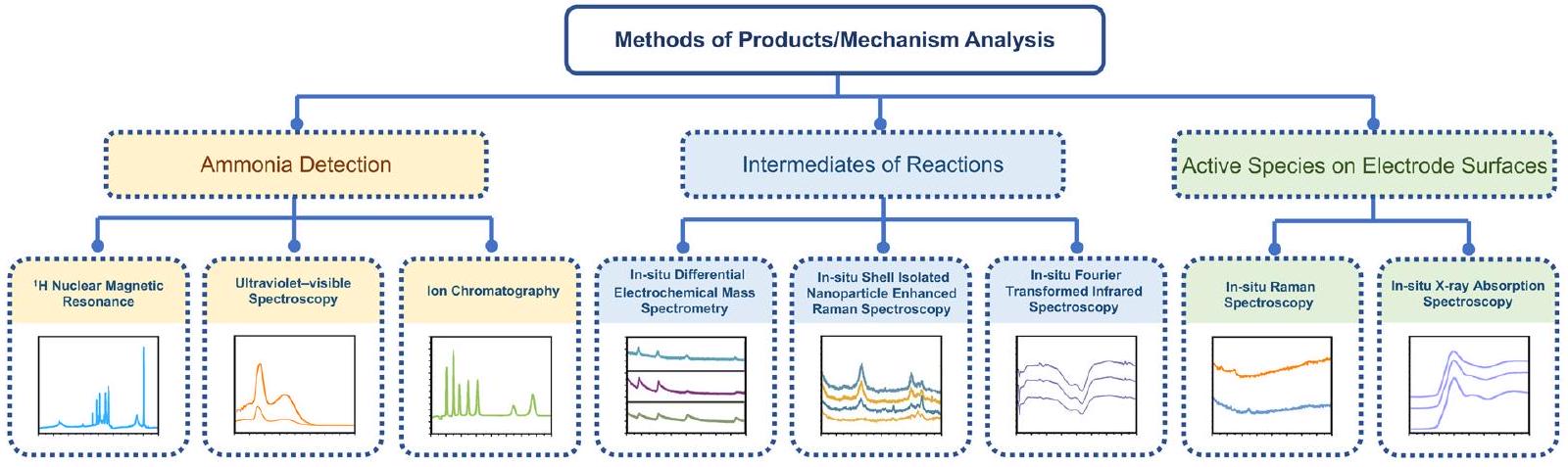
لذلك، ستتناول هذه القسم بشكل رئيسي أحدث الطرق للكشف عن الأمونيا وتقنيات التوصيف في الموقع للتخليق الكهروكيميائي للأمونيا. هيكل هذا القسم موضح بشكل تخطيطي في الشكل 12.
4.1. الكشف عن الأمونيا
استنادًا إلى قانون لامبرت-بير، فإن طيف الأشعة فوق البنفسجية والمرئية هو تقنية كمية يمكن استخدامها لقياس تركيز مادة كيميائية من خلال امتصاص الضوء عند طول موجي نموذجي في الغازات والمحاليل.يمكن قياس المواد المكتشفة باستخدام منحنى المعايرة استنادًا إلى عينات قياسية. في الكشف عن الأمونيا، تعتبر الأشعة فوق البنفسجية والمرئية هي الطريقة الأكثر شيوعًا نظرًا لتكلفتها المنخفضة وسهولة تشغيلها.قبل اختبار الامتصاص، هناك حاجة إلى عوامل ملونة وطريقة الأزرق الإندوفينول هي واحدة من الطرق الملونة المستخدمة على نطاق واسع
والتي تتطلب ثلاثة مواد كيميائية: محلول تارترات الصوديوم والبوتاسيوم وحمض الساليسيليك، محلول هيبوكلوريت الصوديوم، ومحلول نيتروفيريسيانيد الصوديوم.يمكن قياس أقصى امتصاص للأزرق الإندوفينول عند حواليعامل ملون آخر شائع الاستخدام هو كاشف نيسلر، وعادة ما يتم قياس أقصى امتصاص عند حوالي 420 نانومتر. ومع ذلك، فإن طول موجة أقصى امتصاص ليس رقمًا ثابتًا ويتأثر بـ pH المحلول والاختلافات في الطيف.بالإضافة إلى ذلك، يجب ضبط تركيز المادة المكتشفة على نطاق الامتصاص المناسب لكل مطياف. وبالتالي، فإن الأخطاء التي قد تحدث أثناء إعداد المحلول تتضخم عدة مرات خلال إجراء التخفيف، مما يتطلب احتياطات إضافية.
تعتبر IC طريقة شائعة أخرى للكشف عن الأمونيا، حيث تستخدم مبدأ تبادل الأيونات. بالمثل، يجب تخفيف الإلكتروليت إلى نطاق الكشف، ويتطلب الأمر معالجة مسبقة لتجنب تلوث المعدات وتلفها بواسطة المواد العضوية وأيونات المعادن الثقيلة.يجب أن تكون نتائج IC قريبة من الناحية الكمية من نتائج الأشعة فوق البنفسجية والمرئية، مما يؤكد دقة وموثوقية كلا الطريقتين.
على الرغم من أن الطرق الشائعة يمكن أن تكشف عن تركيز الأمونيا بدقة نسبية، فإن تجربة وسم النظائر باستخداميعتبر الرنين المغناطيسي النووي بارزًا في تحديد مصدر النيتروجين للمنتج. قدم زهاو وآخرون المحفزات الكهربية ثنائية المعدن الموزعة ذريًا من الحديد والكوبالت للتقليل الكهروكيميائي للنيتروجين إلى الأمونيا بكفاءة فارادائية استثنائية منأكدت تجربة وسم النظائر على الانتقائية العالية لتقليل النيتروجين، والتي تم تنفيذها باستخداموالمشبعة فيإلكتروليت عند -0.30 فولت (مقابل RHE) وخضعت للتفاعل لمدة ساعتين.تم استخدامه كمذيب لذوبان المعايير الداخلية. للتأهيل، تظهر ثلاث قمم مميزة عند استخدامكمصدر للنيتروجين، وتظهر قمتان فقط عند استخدام.للتكميم، تم معايرة عوائدومع المنحنيات القياسية.تشير القيم المقاربة عن كثب لـوإلى أن الأمونيوم المنتج في هذا التفاعل نشأ منتقليل النيتروجين المحفز بالكوبالت.
الشكل 12 التوضيح التخطيطي لأحدث الطرق للكشف عن الأمونيا وتقنيات التوصيف في الموقع.
مقال مفتوح الوصول. نُشر في 05 فبراير 2024. تم تنزيله في 1/14/2025 6:59:24 صباحًا.
هذا المقال مرخص بموجب رخصة المشاع الإبداعي للاستخدام غير التجاري 3.0.
بالإضافة إلى ذلك، يجب توضيح تركيزات المتفاعلات والمنتجات الثانوية عند قياس أداء إنتاج الأمونيا. بالنسبة للمواد السائلة، مثل النترات والنتريت، يتم اعتماد IC بشكل رئيسي، ويمكن عادةً قياس المنتجات الغازية باستخدام كروماتوغرافيا الغاز (GC).في جميع هذه القياسات، يجب إجراء تكرارات تزيد عن 3 مرات لضمان الاعتمادية.
4.2. الوسائط التفاعلية
نظرًا للمسار الإلكتروني المعقد المتضمن في التخليق الكهروكيميائي للأمونيا،تتكون وسائط متباينة في هذه العملية، مما يزيد من صعوبة توضيح آلية التفاعل الكلي. تعتبر طرق التوصيف في الموقع المناسبة ضرورية لفهم العمليات الكهروكيميائية على المستوى الجزيئي ويجب تطبيقها اعتمادًا على المواقف المختلفة.
4.2.1. قياس طيف الأشعة تحت الحمراء المحولة فورييه في الموقع.
FTIR هي تقنية تستخدم للحصول على طيف الأشعة تحت الحمراء لامتصاص أو انبعاث عينة ليتم تحليلها.في هذه الطريقة، يمكن الكشف عن المجموعة الوظيفية والقمة الأصلية المتعلقة بالجزيئات النموذجية، مما يساعد في تحديد الهيكل وتكوين المواد وفقًا لذلك.
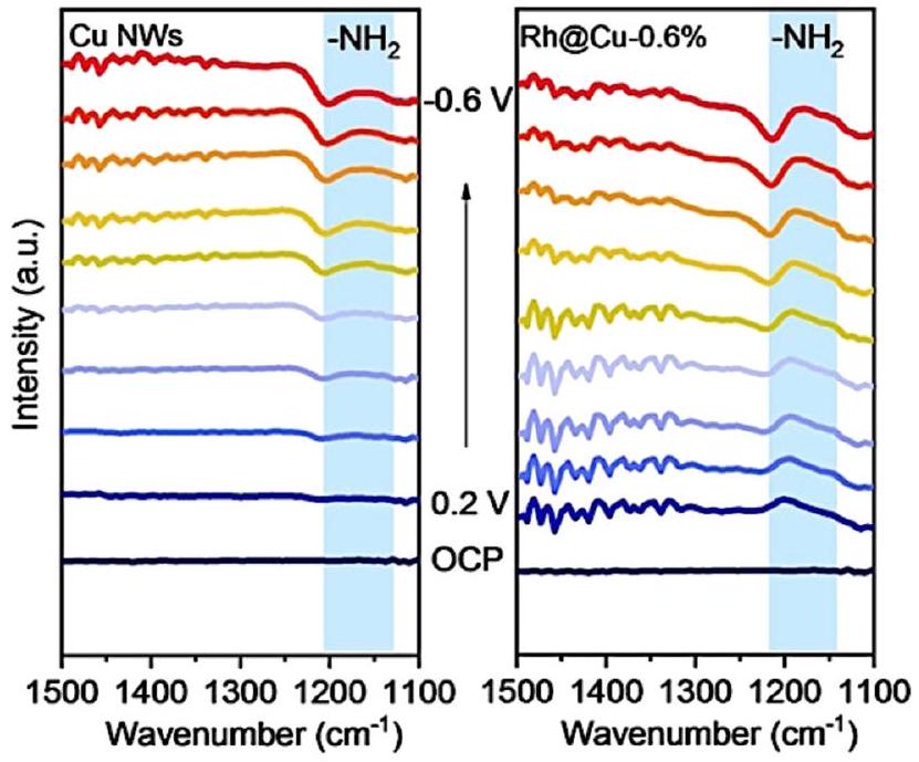
تعتبر FTIR في الموقع، التي رائدها بيويك وآخرون في الثمانينيات، فعالة في الكشف عن المواد الممتصة والجزيئات والوسائط التفاعلية.في تفاعلات إنتاج الأمونيا، عادةً ما يتم استخدام FTIR في الموقع لتمييز الوسائط التفاعلية الممتصة على أقطاب المحفز. استخدم ليو وآخرون هذه التقنية في دراسة آلية تقليل النترات إلى الأمونيا.في عمل ليو، تم تصنيع محفز كهربي جديد يتكون من ذرات مفردة من الروديوم ومجموعات موزعة على أسلاك النحاس النانوية وأظهر نشاطًا عاليًا وانتقائية عالية لتخليق الأمونيا الكهروكيميائي. أظهرت نتائج طيف الأشعة تحت الحمراء في الموقع بوضوح أنه يمكن الكشف عن قمة ضعيفة تتعلق بـيمكن الكشف عنها لأسلاك النحاس النانوية، بينما بعد إدخال ذرات مفردة من الروديوم/المجموعات إلى المحفز الكهربي، يمكن الكشف عن قمة واضحة لـمن خلال مقارنة النتائج، اقترح المؤلفون أن إدخال الروديوم حسّن امتصاص السطح للهيدروجين بشكل كبير، مما يشير إلى أن خطوة الهدرجة لهذا المحفز الكهربي لم تعد الخطوة المحددة لمعدل عملية تقليل النترات (الشكل 13). كانت هذه الفرضية بشأن الآلية متطابقة مع نتائجالرنين المغناطيسي النووي، وDEMS في الموقع، وطيف EPR في الموقع، إلخ. تم اقتراح الآلية ومسار التفاعل الكلي بناءً على هذه النتائج بمساعدة حسابات DFT.
4.2.2. قياس طيف الكتلة الكهروكيميائية التفاضلية في الموقع. تعتبر الكتلة التفاضلية (DEMS)، وهي طريقة كشف عبر الإنترنت، مستخدمة على نطاق واسع لتحديد المنتجات والوسائط بشكل مستمر في التفاعلات الفارادية.في الوقت الحاضر، تلعب DEMS دورًا مهمًا ليس فقط في الدراسات النوعية ولكن أيضًا الكميةلآلية التفاعلات الكهروكيميائية. يتكون نظام DEMS من جهاز تفاعل كهروكيميائي، ونظام إدخال غشاء، ومطياف الكتلة.تدخل الوسائط والمنتجات المتطايرة الناتجة خلال التفاعل الكهروكيميائي إلى الفراغ
الشكل 13 طيف الأشعة تحت الحمراء الكهروكيميائية في الموقع لـ RhaCu-0.6% و Cu NWs تحت إمكانيات مختلفة فيإلكتروليت (pHمعبواسطة ليو وآخرون. أعيد طبعها بإذن من المرجع 83 حقوق الطبع والنشر 2022 وايلي-فيتش GmbH.
قناة مطياف الكتلة من خلال واجهة الغشاء الكارهة للماء، حيث يسجل مطياف الكتلة تيارات الأيونات المختلفة مع مرور الوقت.
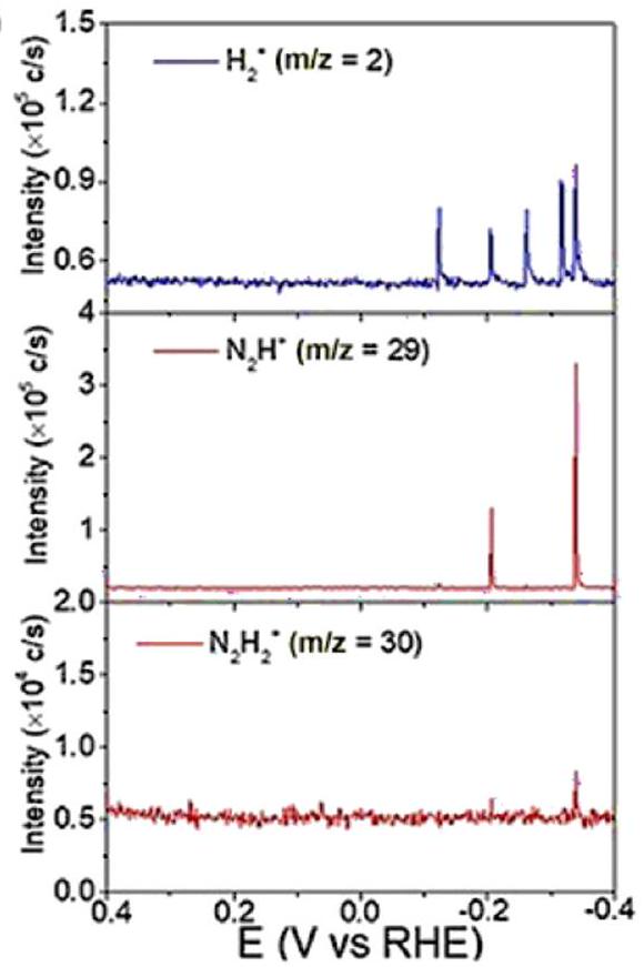
أجرى ياو وآخرون قياسات DEMS إضافية لتأكيد الصيغة الجزيئية لـفي عمل ياو، تم استخدام DEMS لاستكشاف آلية تقليل النيتروجين والنترات على سطح الروديوم. تشير إشارةوإلىو 30 لـتم الكشف عنه من 0.4 فولت إلى -0.4 فولت على قطب كهربائي من فيلم Rh في كل من 0.1 م كOH ومحاليل (مشبعة بالغاز) وفي محلول 0.1 م من هيدروكسيد البوتاسيوم-المشبعة) لتقليل النترات وتقليل النيتروجين، على التوالي. الإشارات لـ و يمكن اكتشافه في كلا التفاعلين، بينما كانت الإشارات لـتم الكشف عنها فقط في تفاعل اختزال النترات (الشكل 14). وأشارت النتائج إلى أنعملت كوسيط في كل من اختزال النترات واختزال النيتروجين. في الوقت نفسه، كانت انتقائية اختزال النيتروجين أقل من تلك الخاصة باختزال النترات إلى الأمونيا، كما يتضح من مقارنة الإشارات لـ. 4.2.3. قياس طيف رامان المعزز بجزيئات نانوية معزولة في الموقع. كانت طيف رامان المعزز بالسطح (SERS)، الذي تم الإبلاغ عنه لأول مرة بواسطة فليشمان في عام 1974، إنجازًا كبيرًا في البحث والتطوير لطيف رامان لحل مشكلة الحساسية المنخفضة.استنادًا إلى SERS، فإن تقنية مطيافية رامان المعززة بجزيئات نانوية معزولة (SHINERS) توسع من عمومية مواد الركيزة وتضاريس السطح،تطورت لتصبح أداة فعالة لوصف التحفيز في السنوات الأخيرة.تعمل الجسيمات النانوية ذات الهيكل القائم على النواة والقشرة على تعزيز إشارات مطيافية رامان فحسب، بل تمنع أيضًا التفاعلات الجانبية الضوئية من المواد المحللة.
كنموذج متقدم في تقنيات مطيافية رامان، يتم تطبيق قياس SHINERS في الموقع غالبًا في تحديد الوسطاء التفاعليين على أسطح المحفزات في
(أ)
(ب)
الشكل 14 (أ) DEMS من ) ، ، و علىخلال مسح من 0.4 إلى -0.4 فولت في وسط مشبع بالأرجونحل ). (ب) نظام إدارة البيانات ، و علىخلال مسح من 0.4 إلى -0.4 فولت فيمحلول KOH بتركيز 1 م مشبع ). أعيد طبعها بإذن من المرجع 152 حقوق الطبع والنشر 2020 وايلي-فيتش فيرلاج GmbH & Co. KGaA، فاينهايم. مجال التحفيز الكهروكيميائي بسبب دقته واستقراره.حتى الآن، قام العديد من الباحثين بتطبيق SHINERS لدراسة الآليات، بما في ذلك تفاعل تطور الهيدروجين، وتفاعل اختزال الأكسجين، وتفاعل اختزال/أكسدة ثاني أكسيد الكربون، وتفاعل اختزال النترات، وغيرها.في تفاعل اختزال النترات، استخدم Jr وآخرون تقنية SHINERS لكشف سلسلة من الوسائط التفاعلية المشاركة في عملية اختزال النترات، مثلوعلى وجه التحديد، في عمل جونيور، تم ملاحظة الوسائط في اختزال النترات بواسطة SHINERS على ثلاثة مستويات بلورية من النحاس، والتي كانت، Cu (111) و Cu (110) على التوالي. كانت الوسائط التي تم ملاحظتها على الطائفتين الثلاث مشابهة، مما يشير إلى نفس الآلية ومسار التفاعل. تم تحليل كل قمة من SHINERS بالتفصيل وتعيينها إلى وسيط تفاعلي. كما هو موضح من النتائج، كانت القمم ذات الشدة المعتدلة عند و يمكن أن يُعهد إلى تشكيلبسبب الأكسدة الجزئية. يمكن ملاحظة ذروتين مميزتين في Cu (110) و Cu (111) ولكن ليس في Cu (100)، مما يشير إلى معدل التكوين المنخفض لـعلى Cu (100)، الذي كان نوعًا نشطًا رئيسيًا على سطح القطب. كانت منحنيات LSV تتماشى مع هذا التفسير للأداء النسبي غير النشط لتقليل النترات.
علاوة على ذلك، قامت هذه الطريقة بالتحقيق في الآلية وراء انخفاض أداء تقليل النترات الناتج عن أيونات الكلوريد.من المعروف أنه يشكل مصفوفة من الكلوريد على سطح النحاس عند حوالي -0.3 فولت مقابل RHE، وقد تم إثبات أنها تعيق اختزال النترات المعتمد على النحاس.أكدت SHINERS هذه الظاهرة وقدمت مسار تفاعل مفصل في هذا العمل (الشكل 15). وفقًا لنتائج SHINERS، لم يكن هناك دليل على امتصاص النيتريت أو أنواع النيتروكسيل عندما تم مسح الجهد من 0 مللي فولت إلى 800 مللي فولت مقارنة بـنظام مجاني. بدلاً من ذلك، قمم ضعيفة مرتبطة بـوظهر عند حوالي -0.5 فولت مقابل RHE على النحاس (100)، مما يعني وجود مسار مختلف لتقليل النترات على أقطاب النحاس المزينة بالكلوريد. أيضًا، ك تقنية كشف سطحية عالية الحساسية، يمكن استخدام SHINERS في الكشف عن الأنواع النشطة على أسطح الأقطاب، والتي سيتم مناقشتها في القسم التالي.
بالإضافة إلى طرق التوصيف في الموقع الثلاث المذكورة أعلاه، هناك بعض التقنيات الأخرى المستخدمة في التحليل في الموقع للوسطاء التفاعليين. تعتبر تقنية IC في الموقع تقنية تعتمد على IC التقليدية وتُجرى للكشف عن الأيونات التي تم توليدها أو استهلاكها على مر الزمن. علاوة على ذلك، تم الإبلاغ في عام 2020 عن نظام IC آلي بالكامل ومنخفض التكلفة للتحليل في الموقع للنتريت والنترات في المياه الطبيعية من قبل باول وآخرين.الرنين المغناطيسي الإلكتروني في الموقع (ESR) هو تقنية طيفية لامتصاص الميكروويف تُستخدم للكشف عن المواد البارامغناطيسية التي تحتوي على إلكترونات غير متزاوجة ودراستها. تلعب الجذور الهيدروجينية دورًا مهمًا في اختزال النترات إلى الأمونيا ويمكن مراقبتها باستخدام ESR في الموقع للمساعدة في توضيح آلية التفاعل.
باختصار، مع تطوير تقنيات الموقع، يتم استخدام المزيد والمزيد من الطرق الجديدة على نطاق واسع لشرح الآليات التحفيزية المعقدة.
4.3. الأنواع النشطة على أسطح الأقطاب
نظرًا لأن العمليات الكهروكيميائية تُدرس عند الواجهة بين إلكتروليت سائل وقطب صلب،تحديد واستكشاف الأنواع النشطة على سطح القطب الكهربائي بشكل شامل أمر مهم. الشائع في الظروف الخارجية
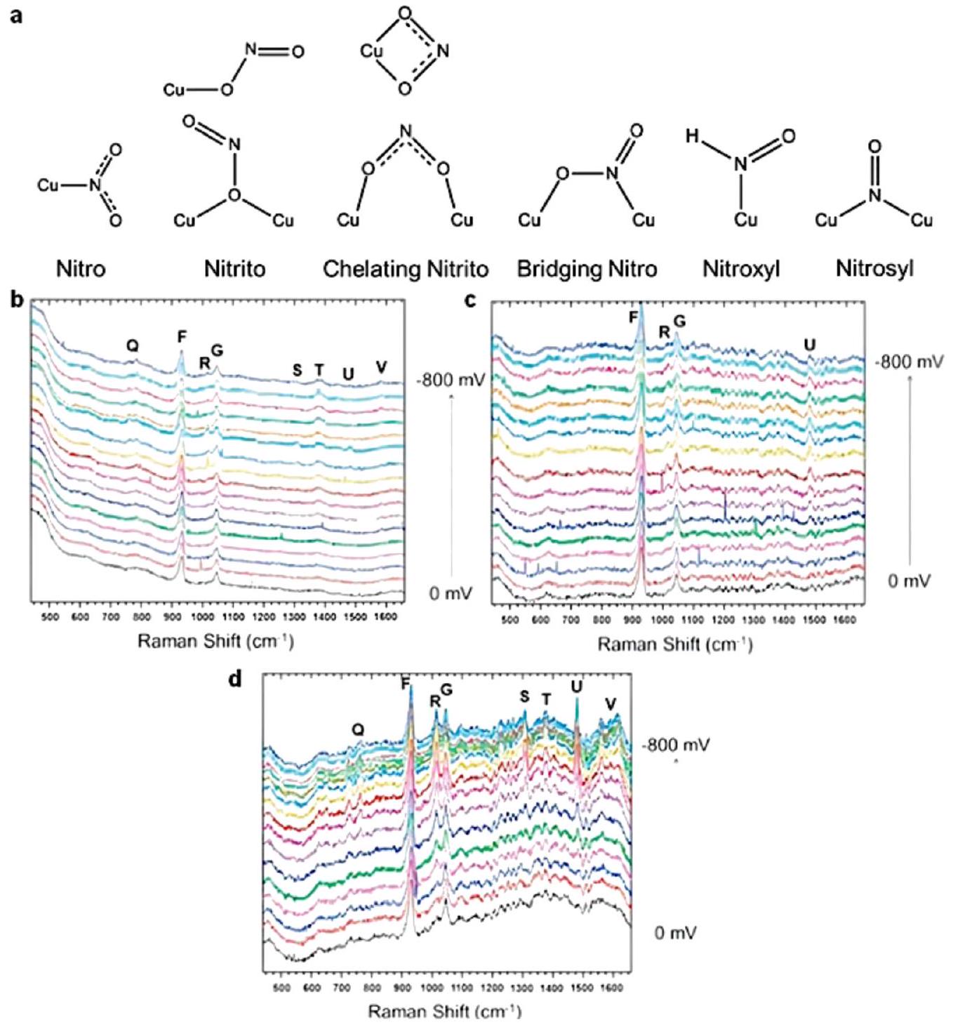
الشكل 15 (أ) أوضاع الامتزاز للنيتريت وأكسيد النيتريك وHNO على سطح النحاس. طيف SHINERS الكهروكيميائي في الموقع تم جمعه من (ب) Cu (100)، (ج) Cu (111)، و(د)فيحل معو 10 مللي مولار من حمض الهيدروكلوريك عند جهد بين 0 و -0.8 فولت مقابلإعادة طبع بإذن من المرجع 157 حقوق الطبع والنشر 2016 إلزيفير المحدودة.
دراسات توصيف المواد الكهربائية يمكن أن تعطي فقط نتائج ثابتة بدلاً من التحليل المستمر خلال عمليات التفاعل الديناميكية. في هذا الصدد، تعتبر دراسات التوصيف الكهروكيميائي في الموقع للأنواع النشطة ضرورية لدراسة وتصميم المحفزات الكهربائية. 4.3.1. قياس طيف رامان في الموقع. يعد طيف رامان في الموقع طريقة قوية لتحديد الأنواع النشطة بسبب الضغط غير المحدود، ودرجة الحرارة، أو وجود غازات التفاعل أثناء عملية القياس.من الناحية النظرية، يمكن أن تكشف مطيافية رامان عن معلومات الهيكل للمواد على مقاييس دقيقة، والتي تتميز بتحولات التردد. على الرغم من أن إشارة مطيافية رامان ضعيفة نسبيًا للأنواع الممتصة على السطح، إلا أنها فعالة جدًا في تحليل الأنواع على سطح الإلكترود. من خلال دمج ميزات مطيافية رامان مع الكيمياء الكهربائية، يمكن تحديد الهيكل والتركيب. يمكن تمييز تطور سطح المحفز الكهربائي بوضوح.
عادةً ما يتم إجراء قياسات طيف رامان الكهروكيميائي في الموقع باستخدام جهاز رامان وخلايا رامان في الموقع متصلة بمحطة عمل كهروكيميائية.كعنصر حاسم، كانت خلية رامان في الموقع تمثل في السابق قيدًا كبيرًا في إجراء هذا القياس.في الوقت الحاضر، تحتوي خلية رامان في الموقع عادةً على قطب عمل، وقطب مضاد، وقطب مرجعي، ونافذة بصرية من الكوارتز. لتجنب تآكل المحلول وتآكل الجهاز بواسطة الغازات، يجب تجهيز خلية رامان بنظام ختم للنافذة البصرية. يجب تجنب التدخل من إشارة المحلول تحت الظروف التجريبية قدر الإمكان باستخدام طبقة رقيقة من المحلول.بين القطب الكهربائي والنافذة)، وهو أمر مهم لأنظمة رامان المجهرية. بصرية سميكة قد تتسبب طبقات النوافذ أو الحلول في تغييرات في المسار البصري لنظام المجهر وتؤثر سلبًا على كفاءة جمع إشارة رامان السطحية.
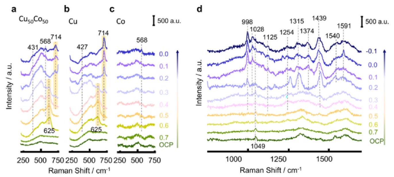
قام فانغ وآخرون بتطبيق طيف SHINERS في استكشاف كل من سطح المحفز والوسطاء المخفضين الممتصين أثناء الـعملية. الطيف بين على، وركزت الشركة بشكل رئيسي على توضيح الخصائص الكيميائية للعامل المساعد على السطح. كما هو موضح في الشكل 16، فإن قمم التوصيف التي تنتمي إلى ( يمكن ملاحظته عندما يكون الجهد فوق 0.6 فولت في و النحاس. ومع ذلك، عندما انخفض الجهد، بدأت القمم للأكاسيد تتقلص تدريجياً. الانخفاض إلى الحالة المعدنية (النحاس) حتى قبل أشارت إلى أن سطح المحفز كان مؤكسدًا جزئيًا بواسطة الهواء وأن المواقع النشطة الحقيقية لـكانت المعادن Cu و Co. بالإضافة إلى ذلك، يمكن تعيين القمم عندوإلىوالتي تسبب بها امتصاص الأكسينيدرايد على سطح المحفز، على التوالي.أوضحت الأطياف بينإشارات النترات والوسائط الممتصة على السطح. مع التحول المحتمل من جهد الدائرة المفتوحة (OCP) إلى -0.1 فولت، ظهرت القمم للنترات والوسائط بالتتابع. بهذه الطريقة، تم اقتراح أن يحدث مسار إزالة الأكسجين في تسلسلبينما تم اقتراح أن يحدث مسار الهدرجة في تسلسل *NO*. علاوة على ذلك، من خلال مقارنة القمم علىو Cu، ظهرت القمة المتعلقة بـ
فقط على سطح Cu، مما يشير إلى قدرتها الضعيفة على مزيد من إزالة الأكسجين من النيتريت.حقق وانغ وآخرون الأنواع التفاعلية المعنية في اختزال النترات لإنتاج الأمونيا من خلال اختبار رامان في الموقع.أشار الطيف الأولي لرامان لهيكل النحاس الشبيه بالجزيرة إلى وجودوكمية صغيرة من CuO. مع حدوث تفاعل الاختزال على سطح القطب، اختفت قمة CuO على الفور بعد تطبيق جهد سالب، بينما زادت شدة القمم لـ أولاً إلى القيمة القصوى ثم
انخفضت تدريجياً مع التحول السلبي في الجهد. وبالتالي، يمكن الاستنتاج أن CuO تم اختزاله أولاً إلىثم تم اختزاله أكثر إلى Cu مع تفاعل اختزال النترات إلى الأمونيا. الاقتراح أعلاه يشير إلى أن المواقع النشطة الحقيقية لاختزال النترات كانت
تكونت خلال عملية الاختزال بدلاً من CuO على القطب الأولي.بالإضافة إلى ذلك، أبلغ تشانغ وآخرون عن محفز كهربائي فعال لإنتاج الأمونيا الخضراء بدءًا من مصفوفات أسلاك CuO النانوية، والتي تم تحويلها بعد ذلك في الموقع إلىمصفوفات أسلاك نانوية خلال عملية اختزال النترات إلى الأمونيا.
تم تأكيد التكهنات بشأن المواقع النشطة أيضًا من خلال قياس طيف رامان في الموقع، والذي كان متوافقًا مع عمل لي.
4.3.2. قياس طيف الامتصاص بالأشعة السينية في الموقع.أصبح قياس طيف الامتصاص بالأشعة السينية (XAS)، استنادًا إلى حافة امتصاص الأشعة السينية للعناصر التي تم ملاحظتها لأول مرة بواسطة موريش دي بروغلي في عام 1913،
تقنية متقدمة لدراسة المواد المعقدة والمزخرفة. يعتمد مبدأ XAS على العلاقة بين تدهور شدة الأشعة السينية وبنية المواد وتركيبها. تدرس XAS العلاقة بين الشدة المنقولة والشدة الساقطة. نظرًا لأن شدة الضوء المنقول مرتبطة بالكتلة العنصرية والذرية، يمكن استخدامها للتحليل النوعي وحتى الكمي للعناصر. اعتمادًا على آلية التكوين وشكل القمم، يمكن تصنيف XAS إلى هيكل امتصاص الأشعة السينية بالقرب من الحافة (XANES) وهيكل امتصاص الأشعة السينية الممتد (EXAFS)، كل منهما يتوافق مع امتصاص الفوتونات منخفضة الطاقة وامتصاص الفوتونات عالية الطاقة، على التوالي.اعتمد تشن وآخرون قياس XAS لتوفير فهم أعمق للخصائص الإلكترونية للمحفز الكهربائي القائم على Cu (Ru-CuNW).تم الإبلاغ عن محفز أسلاك النحاس الموزعة Ru بأداء متميز ليصل إلى تيار من الدرجة الصناعية قدره
لاختزال النترات إلى الأمونيا مع الاحتفاظ بانتقائية عالية (FE بنسبة 93%). لتوضيح الهيكل والتركيب للأداء العاليالشكل 16 أطياف SHINERS بينعلى (أ) ، (ب) Cu، و (ج) Co. (د) أطياف SHINERS بينعلىفي 100
خلال الاستقطاب الكاثودي من 0.7 إلى -0.1 فولت، بواسطة فنج وآخرون. أعيد طبعها بإذن من المرجع 92 حقوق الطبع والنشر 2022 سبرينغر ناتشر.المحفز، تم مراقبة المادة بواسطة كل من XAS في الموقع وXAS خارج الموقع. اقترحت XANES Cu K خارج الموقع أنتم اختزاله إلى الحالة المعدنية Cu بعد الاختزال المسبق. تُظهر XANES Cu K في الموقع بوضوح عملية الاختزال التدريجي من أكسيد إلى معدن. علاوة على ذلك، تم الحفاظ على الحالة المعدنية لـ Cu طوال إجراء اختزال النترات. كما اقترحت XANES Ru K خارج الموقع أنتم اختزاله بنجاح إلى الروثينيوم المعدني بعد الاختزال المسبق، ويمكن أن تحدد XAS في الموقع هذه العملية. تم إثبات أن Ru المعدني هو الموقع النشط لإنتاج الأمونيا أيضًا. بالإضافة إلى ذلك، أوضح هيكل الامتصاص الممتد بالأشعة السينية المحول فورييه (FT-EXAFS) هيكل التنسيق لـNW وÅفقط القمة لـÅ A) يمكن العثور عليها فيÅÅ، كان من الصعب التمييز بينهما. ومع ذلك، تم نسب هذه القمة إلى
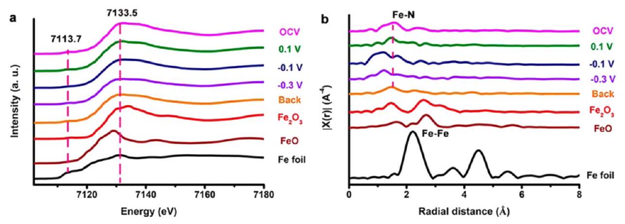
استنادًا إلى دراسات التوصيف الأخرى المذكورة لاحقًا في الورقة.بالمثل، طبق تشونغ وآخرون XAS في الموقع لكشف أصل النشاط العالي لـ FePc-pz في NRR.تم تحديد الحالة الكيميائية لـ Fe وهيكل التنسيق الخاص بها بطريقة عميقة. كما هو موضح في ملف XANES لحافة Fe K في الموقع (الشكل 17)، لم يكن هناك تغيير واضح في تركيب المحفز خلال NRR. عند جهد مختلف، كانت إشارات الرنين السابقة لحواف عينات FePc-pz مختلفة عن تلك الخاصة بأوراق Fe ولكنها مشابهة لإشارات، مما يشير إلى الحالة الكيميائية لـ Fe خلال عملية اختزال النيتروجين. في الوقت نفسه، تم الكشف عن تنسيق مواقعفي NRR من خلال تحليل EXAFS لحافة Fe K في الموقع. مع تحرك الجهد سلبًا، تم نقل القمة المعينة لـمنإلىA، مما يشير إلى أن رابطة Fe-N كانت مضغوطة خلال NRR حيث تفاعلت الوسائط النيتروجينية الممتصة والجذور الهيدروجينية مع مواقع Fe النشطة. ومع ذلك، عندما عاد الجهد إلى جهد الدائرة المفتوحة، ظلت رابطةعند. يمكن الاستنتاج أنه لم يكن هناك ضرر هيكلي في FePc-pz، مما يؤكد استقرارالمواقع النشطة في عملية NRR.
بعيدًا عن طرق التوصيف التي تم مناقشتها في هذا القسم، هناك العديد من التقنيات الأخرى في الموقع التي يمكن استخدامها أيضًا للتحقيق في واجهة التفاعلات الكهروكيميائية، مما يوفر رؤى عميقة في هياكل سطح المواد والآليات المعقدة لتخليق الأمونيا الكهروكيميائية. في الختام، مع تطور تقنيات التوصيف الحديثة، يتم تقديم المزيد والمزيد من الطرق الحديثة في الموقع، مما يساهم بشكل منهجي في تقدم الدراسات الآلية المتعمقة.
5. التطبيق العملي والتحليل الاقتصادي
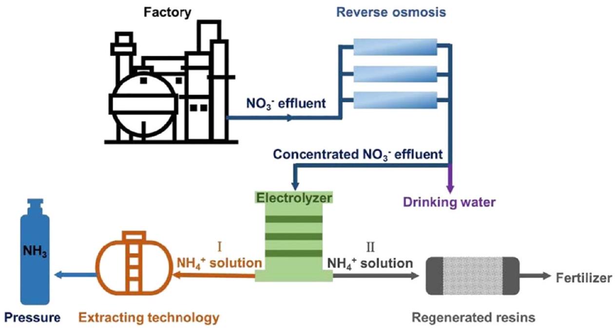
كنموذج يحقق الفائدة للجميع، يوفر اختزال النترات إلى الأمونيا إمكانية إزالة النترات من مياه الصرف الصحي واستعادة الأمونيا.يوضح الشكل 18 تطبيق الاختزال العملي للنترات إلى الأمونيا من مياه الصرف الصحي. حتى الآن، ركزت معظم الأعمال البحثية على جوانب المواد والآلية كما تم تلخيصه في الأقسام السابقة. هناك خطان رئيسيان من الجهود لمعالجة احتياجات التطبيقات العملية: معالجة مياه الصرف الصحي الحقيقية (الغنية بالنترات) وتكبير النماذج.
5.1. تطبيق معالجة مياه الصرف الصحي الحقيقية
بالنسبة لمياه الصرف الصحي البلدية، عادة ما تكون تركيزات النترات في نطاقهذان القيمتان أقل بكثير من التركيز السائد البالغ 0.1 م () المعتمد في، مما يجعل تطبيقه في معالجة مياه الصرف الصحي تحديًا. من المشجع العثور على بعض الأعمال التمثيلية الحديثة التي تركز جهودها على تحويل مياه الصرف الصحي الحقيقية إلى أمونيا باستخدام محفزات قائمة على النحاس.على سبيل المثال، استخدم ما وآخرون مياه الصرف المتدفقة من محطة مياه ستوكهولم كإلكتروليت فيمع تركيز نترات منخفض للغاية قدرهتستخدم القضبان النانوية كتحفيز للاختزال الانتقائي للنترات إلى الأمونيا. بعد التحويل المستمر لمدة 3 ساعات عند -0.6 فولت مقابل RHE،يمكن تحويل النترات إلى أمونيا. كما أبلغ تشاو وآخرون عنقطب كهربائي للاختزال الكامل
الشكل 17 (أ) ملفات XANES لحافة Fe K و (ب) ملفات EXAFS لأوراق Fe،و FePc-pz على ورق الكربون تحت جهود مختلفة مطبقة (من OCP،و -0.3 فولت مقابل RHE، ثم العودة إلى OCP) بواسطة تشونغ وآخرون. أعيد طبعها بإذن من المرجع 166 حقوق الطبع والنشر 2021 الجمعية الكيميائية الأمريكية.
الشكل 18 التوضيح التخطيطي للتطبيق العملي لتحويل النترات إلى الأمونيا من مياه الصرف. أعيد طبعه بإذن من المرجع 50 حقوق الطبع والنشر 2020 وايلي-فيتش.
إزالة النترات بتركيز ابتدائي منفي عام 2023، استخدم وانغ وآخرون غشاءً مستقلًادمج ذرات النحاس الفردية لـفي الترشيح الكهربائي المتدفق.
بالإضافة إلى ذلك، كخاصية هامة لمياه الصرف، فإن الأيونات غير العضوية معقدة ولا مفر منها. تشمل هذه الأيونات كل من الكاتيونات والأنيونات مثل، ، إلخ. يمكن لبعض الكاتيونات أحادية التكافؤ تعزيز الأداء لـعن طريق تشكيل أزواج أيونية محايدة فورية، مما يغير هيكل الطبقة الثنائية للقطب السالب.ستجذب زوج الأيونات الأيون المختزل (النترات)، مما يعزز الاتصال بين الكاثود والأيونات المختزلة ويسهل تقليل النترات بشكل أسهل. بالإضافة إلى ذلك، سيتم قمع تفاعل الهيدروجين (HER) مع نوع وعدد مناسبين من الكاتيونات بسبب التنافر.. في هذه الأثناء، الأيونات الموجبة مثل و تأثير سلبي على. بسبب الاستهلاك المستمر لـستتكون رواسب على القطب السالب، مما يؤدي إلى انسداد المواقع النشطة للتفاعل، وهو ما يعرف أيضًا بالتسمم.وبالمثل، تم الإبلاغ عن أنسيتنافس معضمن نطاق محتمل معين للمواقع النشطة. ومع ذلك، فإن الفروق في إنثالبي الامتزاز للأيونات على أقطاب معينة تؤثر علىيجب تحليل الأداء والحالات المحددة على أساس كل حالة على حدة.
في سياق تطبيق معالجة مياه الصرف الصحي، يوجد مجال كبير للتقدم والتحقيق العلمي. يشمل ذلك استكشاف آثار تركيزات النترات المنخفضة. في الوقت نفسه، فإن إدخال الأيونات غير العضوية في العملية يمثل مجالًا آخر مهمًا للبحث الأكاديمي، مما يبرز أهمية هذه القضايا في هذا المجال.
5.2. توسيع نطاق التطبيق
عادةً على نطاق المختبر، يتم استخدام المفاعلات ذات الغرفة الواحدة والمفاعلات ذات الغرفتين (خلايا H) لتحويل النترات إلى الأمونيا. تحويل مع أحجام غرف تتراوح من (الشكل 19). بالنسبة لإنتاج الأمونيا على نطاق صناعي، يجب أن تكون تكوينات المفاعل أكبر بكثير، قد تصل إلى مئات اللترات أو حتى أمتار مكعبة في الحجم. بالإضافة إلى ذلك، يجب أن يكون المحلول الكهربائي في وضع تدفق لضمان إمداد مستمر وكافٍ من النترات لعملية التحويل.
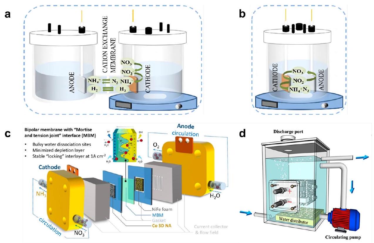
بعض الأعمال الحديثة أخذت هذا الاعتبار إلى مزيد من التطبيقات الصناعية. صمم شيو وآخرون مفاعل غشاء ثنائي القطب للتخليق الكهربائي المستمر للأمونيا من 2000 جزء في المليون من النترات (ما يعادل 0.034 م).من أجل تحقيق التوازن الأيوني، تم اقتراح عملية تقليل النترات باستخدام غشاء ثنائي القطب، وتم زيادة مواقع التحلل المائي من خلال إنشاء واجهة ثلاثية الأبعاد متداخلة جسديًا للغشاء الثنائي القطب في هذا العمل. وقد حقق النظام في النهاية إنتاجًا مستقرًا للأمونيا لأكثر من 100 ساعة عند بكفاءة فارادائية قدرها ومعدل عائد أقصى قدرهيوضح الشكل 19(c) المخطط لمفاعل غشاء ثنائي القطب مع حقل تدفق متعرج يمد الإلكتروليت الجديد. في وقت سابق، في عام 2021، قام زينغ وآخرون بإجراء التجربة الأولى وبناء نموذج أولي لمفاعل بسعة 500 لتر لتحويل النترات من مياه الصرف الكيميائية الحقيقية إلى الأمونيا، محققين كفاءة تحويل.فيفي هذا المفاعل النموذجي، تشكل مجموعتان من الأقطاب الكهربائية مع 13 ورقة قطب الوحدة الكهربائية، المغمورة بالكامل في خزان الإلكتروليت. نشأت هذه الوحدة الكهربائية في مجال الكهروكيمياء الحيوية ولها ميزة عدم التخفيف من مشكلة السعة المحدودة ومواقع التفاعل فحسب، بل أيضًا تجنب تقلبات التركيز بسبب الاستخدام العالي للمساحة.
لتلخيص الأمر، لم يتم دراسة زيادة إنتاج الأمونيا من اختزال النترات بشكل كبير حتى الآن، ومن الضروري إجراء مزيد من البحث حول تصميم الوحدة الكهربائية بشكل خاص. يمكن أن تساهم استكشاف مواد الأقطاب المتقدمة، والمفاعلات القابلة للتوسع، وأنظمة التحكم الاقتصادية في تحسين الأداء والكفاءة.
الشكل 19 التوضيح التخطيطي لـ (أ) مفاعل ذو غرفة واحدة و (ب) مفاعل ذو غرفتين. أعيد طبعه بإذن من المرجع 167 حقوق الطبع والنشر 2023 إلسفير ب.ف. (ج) مفاعل غشاء ثنائي القطب لتخليق الأمونيا في وضع التدفق. أعيد طبعه بإذن من المرجع 176 حقوق الطبع والنشر 2023 سبرينغر ناتشر. (د) مفاعل نموذج أولي لتحويل النترات إلى الأمونيا. أعيد طبعه بإذن من المرجع 175 حقوق الطبع والنشر 2021 الجمعية الكيميائية الأمريكية.
الترتيب، مما يؤدي في النهاية إلى تعزيز الإنتاج المتزايد للأمونيا.
5.3. التحليل الاقتصادي
كما ذُكر أعلاه، فإن الأثر الاقتصادي هو جزء حاسم من التطبيق الصناعي لتحويل النترات إلى الأمونيا.
تُدرج الفوائد الاقتصادية لهذه الاستراتيجية أدناه. أولاً، بالمقارنة مع الطريقة التقليدية هابر-بوش، التي تُعتبر أيضاً التيار السائد حالياً في إنتاج الأمونيا، فإن تحويل النترات إلى أمونيا أكثر استدامة وقابلية للتطبيق مع الكهرباء المتجددة الرخيصة. ثانياً، يُمكن أن يُمكّن مفهوم تحويل النفايات إلى كنز. تلوث النترات شائع في أنواع مختلفة من مياه الصرف الصحي ضمن نطاق طبيعي منبينما يمكن أن يتجاوز هذه القيمةفي بعض الصناعات مثل الأسمدة، المعادن، المتفجرات، إلخ. ثالثًا، مقارنةً بـ NRR، فإن أداءفي المختبر أقرب بكثير إلى المتطلبات العملية، حيث يتجاوز الطيار الحواجز المخبرية.
تشمل التكلفة الاقتصادية لتحويل النترات إلى الأمونيا بشكل أساسي التكلفة الأولية لبناء النظام وتركيبه، والتشغيل والصيانة، والمراقبة والامتثال. ومن بين هذه العوامل، يُعتبر استهلاك الطاقة وتكلفة مواد الأقطاب عاملين حاسمين في عملية التطبيق.
في هذه المرحلة المبكرة من التطبيق العملي، تولي العديد من الأبحاث اهتمامًا للتحليل الاقتصادي. قام مكيناني وآخرون بإجراء تحليل تقني اقتصادي أولي يأخذ في الاعتبار فقط تكلفة الكهرباء لإنتاج نترات الأمونيوم.في هذا العمل، تشير الاعتبارات التقنية والاقتصادية الأولية إلى أن الطريق لإعادة تدوير النترات المستهلكة إلى الأمونيوم المنتجات واعدة وأن التحويل الكامل إلى الأمونيا قد يكون ممكنًا إذا كانت استهلاك الكهرباء منخفضًا بما فيه الكفاية. ومع ذلك، فإن التكاليف الرأسمالية، وسعر الكهرباء، وكفاءة الخلايا تُقدّر بأسعار معينة، وقد ذكر المؤلفون أيضًا أنه يجب أخذ هذه القيم العملية بعين الاعتبار لمزيد من الاستكشاف. درس غاو وآخرون التكلفة الاقتصادية لاستهلاك الطاقة بناءً على معلمة متعلقة بالطاقة، والتي تحددها الطاقة وعائد الأمونيا.في هذا العمل، يتم تقديم منطقة مربحة حيث تكون تركيزات النترات العالية وتكاليف الكهرباء المنخفضة مفيدة. ومن الجدير بالذكر أن هذه العملية لتحويل النترات إلى الأمونيا تقضي أيضًا على تلوث النترات، في حين يُفترض أن عملية النترجة/إزالة النترات العادية لها تكلفة تقديرية تبلغلكل كيلوجرام من النيتروجين المُزال.من منظور إزالة النترات، توقع وانغ وآخرون استهلاك الطاقة لهذه الاستراتيجية باستخدامإلكترود والقطب الكهربائي، الذي هونترات-N و نترات ن ، على التوالي. وفقًا لمتوسط تكلفة الكهرباء الصناعية الحالية ( لكل كيلووات ساعة )، تكلفة استهلاك الكهرباء باستخدام يُقدَّر أن تكون الأقطاب الكهربائيةلكل كيلوجرام من النيتروجين المزال.
على الرغم من أن الأقطاب الكهربائية هي مكون رئيسي في المفاعل، إلا أن تحليلها الاقتصادي لم يتم بشكل كافٍ. لقد تم التعرف على المحفزات القائمة على النحاس على نطاق واسع لنشاطها العالي وانتقائيتها في تحويل النترات إلى الأمونيا. في الوقت نفسه، فإن سعر شبكة النحاس الأصفر (من النحاس (Cu) هولكلالذي يناسب بلا شك التطبيقات الصناعية. بالإضافة إلى ذلك، فإن عاملًا آخر مرتبط ارتباطًا وثيقًا بتكلفة القطب هو متانة المادة نفسها، والتي يجب أخذها بعين الاعتبار على أساس كل حالة على حدة في التحليل الاقتصادي.
في الختام، تكشف التقارير الحالية إلى حد ما عن الوعد الكبير لاستراتيجية تحويل النترات إلى الأمونيا، ولكن من الصعب الوصول إلى تقييم دقيق بسبب الفجوات في التحليل الاقتصادي ذي الصلة. للمستقبل، يُوصى بإجراء دراسة جدوى مفصلة تأخذ في الاعتبار جميع العوامل المذكورة أعلاه لتحقيق تحليل اقتصادي دقيق.
6. الخاتمة وآفاق المستقبل
إنتاج الأمونيا الكهروكيميائي من النترات ( ) يعد واعدًا وجذابًا للغاية بسبب ظروف التفاعل المحيطة، وانخفاض استهلاك الطاقة، و انبعاثات صفرية. تلخص هذه المراجعة التقدم الأخير في توضيح آلية ، المحفزات القائمة على النحاس المتطورة لـ ، طرق التحليل المقابلة لاكتشاف المنتجات، التطبيقات العملية والتحليل الاقتصادي الذي تم إجراؤه حتى الآن.
في السنوات الأخيرة، تم بذل محاولات كبيرة من قبل الباحثين لتصميم وتطوير محفزات فعالة ومنخفضة التكلفة لهذه التفاعل. تُظهر المحفزات القائمة على النحاس بالتأكيد حركيات بارزة مع انتقائية نحو تخليق الأمونيا. تركز معظم الأعمال البحثية الحالية بشكل رئيسي على زيادة الكفاءة الكهربائية وتقليل الفائض الكهربائي، بهدف تحسين إنتاج الأمونيا وانتقائية الأمونيا. من بينها، تعرض المواد النانوية ذات الهياكل المحدودة المزيد من المواقع النشطة من خلال مساحة سطح محددة أكبر، مما يعزز بشكل كبير نشاط المادة. أيضًا، تم تحقيق إنجازات كبيرة في كشف الآليات العميقة لـ مؤخرًا. من ناحية، توفر الحسابات النظرية رؤى حول مسارات التفاعل وتبرر سلسلة من الملاحظات التجريبية. علاوة على ذلك، يمكن محاكاة وتلخيص اتجاهات النشاط والانتقائية لمختلف المحفزات، مما يوفر إرشادات لفرز وتصميم محفزات فعالة. من ناحية أخرى، يتيح الاستخدام الواسع لطرق التوصيف في الموقع الملاحظة التجريبية المباشرة أثناء التفاعلات في الوقت الحقيقي، مما يوفر وسيلة قوية لكشف الوسطاء التفاعليين والأنواع النشطة على سطح القطب.
على الرغم من الإمكانات الكبيرة لإنتاج الأمونيا الكهروكيميائية عبر تقليل النترات، إلا أنه لا يزال بعيدًا عن التطبيق في البيئة الحقيقية ويواجه بعض التحديات التي تحتاج إلى استكشاف وحل. أولاً، كقلق كبير في الصناعة، يجب تحسين الاستقرار طويل الأمد لـ المحفزات القائمة على خلال بشكل كبير. على الرغم من أن العديد من المحفزات القائمة على النحاس المبلغ عنها يمكن أن تصل إلى كفاءة كهربائية عالية تزيد عن ، لا تزال مشاكل التآكل والانحلال موجودة خاصة في البيئات الحمضية، مما يؤدي إلى استقرار أقل. لذلك، يجب أن تركز جهود البحث والتطوير المستقبلية على تحسين استقرار المحفزات القائمة على النحاس. يمكن تحقيق ذلك من خلال استراتيجيات متنوعة، مثل استخدام مواد الدعم لمنع تكتل جزيئات النحاس، وإدخال عوامل مثبتة لتثبيط تسرب أيونات النحاس، وتعديل طريقة تحضير المحفز للتحكم في حالة أكسدة النحاس. على سبيل المثال، تم الإبلاغ عن أن
محفزات النحاس ذات الذرة الواحدة من المرجح أن تظهر استقرارًا ملحوظًا بسبب التفاعلات القوية بين ذرات النحاس وذرات التنسيق المقابلة.
ثانيًا، ستؤدي طريقة تصنيع الأقطاب التقليدية باستخدام روابط بوليمرية (معظمها نافيون) لتثبيت المحفز على سطح القطب إلى استخدام غير فعال للمحفز، وانخفاض في الموصلية وضعف في نقل الكتلة. علاوة على ذلك، فإن استخدام محلول نافيون المكلف يزيد من التكاليف في عملية تحضير الأقطاب، مما يزيد من التكلفة الاقتصادية الإجمالية. لذلك، فإن المحفزات المدعومة ذاتيًا التي يمكن استخدامها مباشرة كأقطاب تحفيزية هي حل واعد لهذه المشكلة.
ثالثًا، يجب تطوير مفاعلات كبيرة الحجم لتناسب متطلبات إنتاج الأمونيا العملية. يتيح تكبير المفاعل تحقيق أقصى معدل تفاعل وزيادة كبيرة في إنتاج الأمونيا العملي. ومع ذلك، مع زيادة حجم المفاعل، يصبح من المهم النظر بشكل شامل في تحقيق كفاءة كهربائية مثالية، وكفاءة الطاقة، وكفاءة اقتصادية، والتي كانت عادة ما تُهمل في المفاعلات على نطاق المختبر. لذلك، يجب تصميم المفاعل بشكل عقلاني وظروف التفاعل المثلى مثل جهد الخلية، ودرجة الحرارة، ونوع/تركيز الإلكتروليت يجب تحديدها. علاوة على ذلك، يجب إجراء تحقيق متعمق في آليات نقل الكتلة/الشحنة على مستوى الخلية.
رابعًا، يجب أن تهدف جهود البحث المستقبلية إلى تطوير محفزات كهروكيميائية قادرة على تحويل النترات بكفاءة عبر مجموعة واسعة من التركيزات، من التركيزات المنخفضة التي توجد عادة في المياه الجوفية (مثل 20 جزء في المليون) إلى التركيزات العالية الموجودة في مياه الصرف الصناعي (مثل 1000 جزء في المليون). إن تطوير أنظمة كهروكيميائية تعالج بفعالية هذه النطاقات الواسعة من مستويات النترات أمر حاسم للتطبيقات العملية في معالجة البيئة والعمليات الصناعية.
وأخيرًا وليس آخرًا، يجب استخدام رؤى حول التقديرات الاقتصادية بطريقة مهنية ومفصلة، بما في ذلك تكلفة استهلاك الطاقة، واستهلاك المحفز، وبناء المفاعل، وما إلى ذلك.
في الختام، سيصبح تطوير تفاعلات إنتاج الأمونيا الكهروكيميائية من نطاق المختبر إلى نطاق عملي هو الاتجاه في البحث في هذا المجال. سيحدث تطوير إنتاج الأمونيا الكهروكيميائية عبر تقليل النترات ثورة في اقتصاد الأمونيا المستدام في المستقبل، مع كون المحفزات القائمة على النحاس هي الأساس.
مساهمات المؤلفين
اقترح L. A. موضوع المراجعة. اقترح X. Z. مخطط المراجعة. كتب K. Z. المسودة. ساهم جميع المؤلفين في تحرير المسودة.
تعارض المصالح
يعلن المؤلفون عدم وجود أي تعارض في المصالح.
مقالة مفتوحة الوصول. نشرت في 05 فبراير 2024. تم تنزيلها في 1/14/2025 6:59:24 صباحًا.
هذه المقالة مرخصة بموجب رخصة المشاع الإبداعي للاستخدام غير التجاري 3.0.
شكر وتقدير
نشكر الدعم من المؤسسة الوطنية للعلوم الطبيعية في الصين (رقم 22205187)، جامعة بوليتكنيك هونغ كونغ (CD4D و WZ4Q)، ومنحة تم تلقيها من معهد الأبحاث للطاقة الذكية (CDA4) في جامعة بوليتكنيك هونغ كونغ.
References
1 J. G. Chen, R. M. Crooks, L. C. Seefeldt, K. L. Bren, R. M. Bullock, M. Y. Darensbourg, P. L. Holland, B. Hoffman, M. J. Janik and A. K. Jones, Science, 2018, 360, eaar6611.
2 D. Saygin, H. Blanco, F. Boshell, J. Cordonnier, K. Rouwenhorst, P. Lathwal and D. Gielen, Sustainability, 2023, 15, 1623.
3 S. Chatterjee, R. K. Parsapur and K.-W. Huang, ACS Energy Lett., 2021, 6, 4390-4394.
4 V. Smil, Enriching the Earth: Fritz Haber, Carl Bosch, and the Transformation of World Food Production, MIT Press, 2004.
5 M. Capdevila-Cortada, Nat. Catal., 2019, 2, 1055.
6 E. Meloni, G. Iervolino, C. Ruocco, S. Renda, G. Festa, M. Martino and V. Palma, Energies, 2022, 15, 3588.
7 B. H. Suryanto, H.-L. Du, D. Wang, J. Chen, A. N. Simonov and D. R. MacFarlane, Nat. Catal., 2019, 2, 290-296.
8 Y. Chen, H. Liu, N. Ha, S. Licht, S. Gu and W. Li, Nat. Catal., 2020, 3, 1055-1061.
9 D. R. MacFarlane, P. V. Cherepanov, J. Choi, B. H. Suryanto, R. Y. Hodgetts, J. M. Bakker, F. M. F. Vallana and A. N. Simonov, Joule, 2020, 4, 1186-1205.
10 M. C. Etter, Acc. Chem. Res., 1990, 23, 120-126.
11 H. Liu, H. Wang and J. Xu, CIESC J., 2022, 73, 32-45.
12 B. Han, J. Liu, C. Lee, C. Lv and Q. Yan, Small Methods, 2023, 2300277.
13 C. Lv, C. Yan, G. Chen, Y. Ding, J. Sun, Y. Zhou and G. Yu, Angew. Chem., 2018, 130, 6181-6184.
14 S. Chen, S. Perathoner, C. Ampelli, C. Mebrahtu, D. Su and G. Centi, Angew. Chem., Int. Ed., 2017, 56, 2699-2703.
15 M. Khalid, M. R. Hatshan, A. M. B. Honorato, B. Kumar and H. Varela, Nanomaterials for Electrocatalysis, Elsevier, 2022, pp. 317-334.
16 S. Z. Andersen, V. Colić, S. Yang, J. A. Schwalbe, A. C. Nielander, J. M. McEnaney, K. Enemark-Rasmussen, J. G. Baker, A. R. Singh and B. A. Rohr, Nature, 2019, 570, 504-508.
17 C. Tang and S.-Z. Qiao, Chem. Soc. Rev., 2019, 48, 3166-3180.
18 Z. Geng, Z. Chen, Z. Li, X. Qi, X. Yang, W. Fan, Y. Guo, L. Zhang and M. Huo, Dalton Trans., 2018, 47, 11104-11112.
19 H. Shen, C. Choi, J. Masa, X. Li, J. Qiu, Y. Jung and Z. Sun, Chem, 2021, 7, 1708-1754.
20 P. Wei, J. Liang, Q. Liu, L. Xie, X. Tong, Y. Ren, T. Li, Y. Luo, N. Li and B. Tang, J. Colloid Interface Sci., 2022, 615, 636-642.
21 M. J. Moorcroft, J. Davis and R. G. Compton, Talanta, 2001, 54, 785-803.
22 B. T. Nolan, K. J. Hitt and B. C. Ruddy, Environ. Sci. Technol., 2002, 36, 2138-2145.
23 P. H. van Langevelde, I. Katsounaros and M. T. Koper, Joule, 2021, 5, 290-294.
24 S. Garcia-Segura, M. Lanzarini-Lopes, K. Hristovski and P. Westerhoff, Appl. Catal., B, 2018, 236, 546-568.
25 Y. Wang, Y. Yu, R. Jia, C. Zhang and B. Zhang, Natl. Sci. Rev., 2019, 6, 730-738.
26 M. Karamad, T. J. Goncalves, S. J. Villegas, I. Gates and S. Siahrostami, Faraday Discuss., 2023, 243, 502-519.
27 H. Shin, S. Jung, S. Bae, W. Lee and H. Kim, Environ. Sci. Technol., 2014, 48, 12768-12774.
28 L. Mattarozzi, S. Cattarin, N. Comisso, R. Gerbasi, P. Guerriero, M. Musiani and E. Verlato, Electrochim. Acta, 2017, 230, 365-372.
29 G. Dima, A. De Vooys and M. Koper, J. Electroanal. Chem., 2003, 554, 15-23.
30 D. Reyter, D. Bélanger and L. Roué, J. Hazard. Mater., 2011, 192, 507-513.
31 J. F. Su, I. Ruzybayev, I. Shah and C. Huang, Appl. Catal., B, 2016, 180, 199-209.
32 O. Peng, Q. Hu, X. Zhou, R. Zhang, Y. Du, M. Li, L. Ma, S. Xi, W. Fu and Z.-X. Xu, ACS Catal., 2022, 12, 15045-15055.
33 T. Hu, C. Wang, M. Wang, C. M. Li and C. Guo, ACS Catal., 2021, 11, 14417-14427.
34 H. Wan, A. Bagger and J. Rossmeisl, Angew. Chem., 2021, 133, 22137-22143.
35 Y. Wang, C. Wang, M. Li, Y. Yu and B. Zhang, Chem. Soc. Rev., 2021, 50, 6720-6733.
36 M. De Groot and M. Koper, J. Electroanal. Chem., 2004, 562, 81-94.
37 R. Lange, E. Maisonhaute, R. Robin and V. Vivier, Electrochem. Commun., 2013, 29, 25-28.
38 D. Sicsic, F. Balbaud-Célérier and B. Tribollet, Eur. J. Inorg. Chem., 2014, 6174-6184.
39 I. Katsounaros, Curr. Opin. Electrochem., 2021, 28, 100721.
40 K. Vetter, Z. Elektrochem., 1959, 63, 1189-1191.
41 E. Abel, H. Schmid and J. Schafranik, Z. Phys. Chem., 1931, 1931, 510-522.
42 D. Anastasiadou, Y. van Beek, E. J. Hensen and M. Costa Figueiredo, Electrochem. Sci. Adv., 2022, e2100220.
43 M. G. De Chialvo and A. Chialvo, Electrochim. Acta, 1998, 44, 841-851.
44 D. Xu, Y. Li, L. Yin, Y. Ji, J. Niu and Y. Yu, Front. Environ. Sci. Eng., 2018, 12, 1-14.
45 X. Lu, H. Song, J. Cai and S. Lu, Electrochem. Commun., 2021, 129, 107094.
46 J. Martínez, A. Ortiz and I. Ortiz, Appl. Catal., B, 2017, 207, 42-59.
47 X. Deng, Y. Yang, L. Wang, X. Z. Fu and J. L. Luo, Adv. Sci., 2021, 8, 2004523.
48 T. Ren, K. Ren, M. Wang, M. Liu, Z. Wang, H. Wang, X. Li, L. Wang and Y. Xu, Chem. Eng. J., 2021, 426, 130759.
49 J. Gao, B. Jiang, C. Ni, Y. Qi and X. Bi, Chem. Eng. J., 2020, 382, 123034.
Open Access Article. Published on 05 February 2024. Downloaded on 1/14/2025 6:59:24 AM.
This article is licensed under a Creative Commons Attribution-NonCommercial 3.0 Unported Licence.
50 Y. Wang, W. Zhou, R. Jia, Y. Yu and B. Zhang, Angew. Chem., Int. Ed., 2020, 59, 5350-5354.
51 D. Hao, Z.-g Chen, M. Figiela, I. Stepniak, W. Wei and B.J. Ni, J. Mater. Sci. Technol., 2021, 77, 163-168.
52 J.-X. Liu, D. Richards, N. Singh and B. R. Goldsmith, Catal., 2019, 9, 7052-7064.
53 F. Wang, Y. p Liu, H. Zhang and K. Chu, ChemCatChem, 2019, 11, 1441-1447.
54 X. Nie, M. R. Esopi, M. J. Janik and A. Asthagiri, Angew. Chem., 2013, 125, 2519-2522.
55 X. Nie, W. Luo, M. J. Janik and A. Asthagiri, J. Catal., 2014, 312, 108-122.
56 T. F. Jaramillo, K. P. Jørgensen, J. Bonde, J. H. Nielsen, S. Horch and I. Chorkendorff, Science, 2007, 317, 100-102.
57 J. Greeley, T. F. Jaramillo, J. Bonde, I. Chorkendorff and J. K. Nørskov, Nat. Mater., 2006, 5, 909-913.
58 Z.-Y. Wu, M. Karamad, X. Yong, Q. Huang, D. A. Cullen, P. Zhu, C. Xia, Q. Xiao, M. Shakouri and F.-Y. Chen, Nat. Commun., 2021, 12, 2870.
59 S. Zhang, M. Han, T. Shi, H. Zhang, Y. Lin, X. Zheng, L. R. Zheng, H. Zhou, C. Chen and Y. Zhang, Nat. Sustainability, 2022, 1-11.
60 A. De Vooys, R. Van Santen and J. Van Veen, J. Mol. Catal. A: Chem., 2000, 154, 203-215.
61 D. Çirmi, R. Aydın and F. Köleli, J. Electroanal. Chem., 2015, 736, 101-106.
62 A. D. McNaught and A. Wilkinson, Compendium of Chemical Terminology, Blackwell Science Oxford, 1997.
63 M. J. Liu, J. Guo, A. S. Hoffman, J. H. Stenlid, M. T. Tang, E. R. Corson, K. H. Stone, F. Abild-Pedersen, S. R. Bare and W. A. Tarpeh, J. Am. Chem. Soc., 2022, 144, 5739-5744.
64 Z. N. Zhang, Q. L. Hong, X. H. Wang, H. Huang, S. N. Li and Y. Chen, Small, 2023, 2300530.
65 D. Pletcher and Z. Poorabedi, Electrochim. Acta, 1979, 24, 1253-1256.
66 L. Palmisano, V. Augugliaro, A. Sclafani and M. Schiavello, J. Phys. Chem., 1988, 92, 6710-6713.
67 N. Furuya and H. Yoshiba, J. Electroanal. Chem. Interfacial Electrochem., 1990, 291, 269-272.
68 N. Furuya and H. Yoshiba, J. Electroanal. Chem. Interfacial Electrochem., 1989, 263, 171-174.
69 Q. Wang, G. Zheng, S. Hao, X. Liu, J. Zheng, Y. Wang, Z. Su, N. Xu, Y. He and L. Lei, ACS Sustainable Chem. Eng., 2019, 8, 44-49.
70 L. Janssen, M. Pieterse and E. Barendrecht, Electrochim. Acta, 1977, 22, 27-30.
71 H. Wang, Y. Li, C. Li, K. Deng, Z. Wang, Y. Xu, X. Li, H. Xue and L. Wang, J. Mater. Chem. A, 2019, 7, 801-805.
72 H. Y. F. Sim, J. R. T. Chen, C. S. L. Koh, H. K. Lee, X. Han, G. C. Phan-Quang, J. Y. Pang, C. L. Lay, S. Pedireddy and I. Y. Phang, Angew. Chem., 2020, 132, 17145-17151.
73 M. I. Ahmed, C. Liu, Y. Zhao, W. Ren, X. Chen, S. Chen and C. Zhao, Angew. Chem., Int. Ed., 2020, 59, 21465-21469.
74 Y. Wang, A. Xu, Z. Wang, L. Huang, J. Li, F. Li, J. Wicks, M. Luo, D.-H. Nam and C.-S. Tan, J. Am. Chem. Soc., 2020, 142, 5702-5708.
75 J. Li, G. Zhan, J. Yang, F. Quan, C. Mao, Y. Liu, B. Wang, F. Lei, L. Li and A. W. Chan, J. Am. Chem. Soc., 2020, 142, 7036-7046.
76 L. Su, K. Li, H. Zhang, M. Fan, D. Ying, T. Sun, Y. Wang and J. Jia, Water Res., 2017, 120, 1-11.
77 F.-Y. Chen, Z.-Y. Wu, S. Gupta, D. J. Rivera, S. V. Lambeets, S. Pecaut, J. Y. T. Kim, P. Zhu, Y. Z. Finfrock and D. M. Meira, Nat. Nanotechnol., 2022, 1-9.
78 H. Jiang, G. F. Chen, O. Savateev, J. Xue, L. X. Ding, Z. Liang, M. Antonietti and H. Wang, Angew. Chem., Int. Ed., 2023, 62, e202218717.
79 Z. Zhang, Y. Liu, X. Su, Z. Zhao, Z. Mo, C. Wang, Y. Zhao, Y. Chen and S. Gao, Nano Res., 2023, 1-10.
80 M. Xie, S. Tang, Z. Li, M. Wang, Z. Jin, P. Li, X. Zhan, H. Zhou and G. Yu, J. Am. Chem. Soc., 2023, 45, 13957-13967.
81 P. Li, L. Liao, Z. Fang, G. Su, Z. Jin and G. Yu, Proc. Natl. Acad. Sci., 2023, 120, e2305489120.
82 X. Fu, X. Zhao, X. Hu, K. He, Y. Yu, T. Li, Q. Tu, X. Qian, Q. Yue and M. R. Wasielewski, Appl. Mater. Today, 2020, 19, 100620.
83 H. Liu, X. Lang, C. Zhu, J. Timoshenko, M. Rüscher, L. Bai, N. Guijarro, H. Yin, Y. Peng and J. Li, Angew. Chem., 2022, e202202556.
84 W. Gao, K. Xie, J. Xie, X. Wang, H. Zhang, S. Chen, H. Wang, Z. Li and C. Li, Adv. Mater., 2023, 35, 2202952.
85 K. Wu, C. Sun, Z. Wang, Q. Song, X. Bai, X. Yu, Q. Li, Z. Wang, H. Zhang and J. Zhang, ACS Mater. Lett., 2022, 4, 650-656.
86 Y. Xue, Q. Yu, Q. Ma, Y. Chen, C. Zhang, W. Teng, J. Fan and W.-x Zhang, Environ. Sci. Technol., 2022, 56, 14797-14807.
87 J. Yang, H. Qi, A. Li, X. Liu, X. Yang, S. Zhang, Q. Zhao, Q. Jiang, Y. Su and L. Zhang, J. Am. Chem. Soc., 2022, 144, 12062-12071.
88 H. Chen, C. Zhang, L. Sheng, M. Wang, W. Fu, S. Gao, Z. Zhang, S. Chen, R. Si and L. Wang, J. Hazard. Mater., 2022, 434, 128892.
89 C. Wang, F. Ye, J. Shen, K.-H. Xue, Y. Zhu and C. Li, Appl. Mater. Interfaces, 2022, 14, 6680-6688.
90 J. Qin, L. Chen, K. Wu, X. Wang, Q. Zhao, L. Li, B. Liu and Z. Ye, ACS Appl. Energy Mater., 2021, 5, 71-76.
91 Z. Gong, W. Zhong, Z. He, Q. Liu, H. Chen, D. Zhou, N. Zhang, X. Kang and Y. Chen, Appl. Catal., B, 2022, 305, 121021.
92 J.-Y. Fang, Q.-Z. Zheng, Y.-Y. Lou, K.-M. Zhao, S.-N. Hu, G. Li, O. Akdim, X.-Y. Huang and S.-G. Sun, Nat. Commun., 2022, 13, 7899.
93 Y. Zhang, X. Chen, W. Wang, L. Yin and J. C. Crittenden, Appl. Catal., B, 2022, 310, 121346.
94 C. Wang, Z. Liu, T. Hu, J. Li, L. Dong, F. Du, C. Li and C. Guo, ChemSusChem, 2021, 14, 1825-1829.
95 X. Zhang, C. Wang, Y. Guo, B. Zhang, Y. Wang and Y. Yu, J. Mater. Chem. A, 2022, 10, 6448-6453.
96 F. Yang, D. Deng, X. Pan, Q. Fu and X. Bao, Natl. Sci. Rev., 2015, 2, 183-201.
Open Access Article. Published on 05 February 2024. Downloaded on 1/14/2025 6:59:24 AM.
This article is licensed under a Creative Commons Attribution-NonCommercial 3.0 Unported Licence.
97 V. Rosca, M. Duca, M. T. de Groot and M. T. Koper, Chem. Rev., 2009, 109, 2209-2244.
98 D. Reyter, D. Bélanger and L. Roué, Electrochim. Acta, 2008, 53, 5977-5984.
99 R. Li, T. Gao, W. Qiu, M. Xie, Z. Jin and P. Li, Nano Res., 2023, 1-6.
100 Z. Li, S. Ji, Y. Liu, X. Cao, S. Tian, Y. Chen, Z. Niu and Y. Li, Chem. Rev., 2019, 120, 623-682.
101 Y. Liu, W. Qiu, P. Wang, R. Li, K. Liu, K. M. Omer, Z. Jin and P. Li, Appl. Catal., B, 2024, 340, 123228.
102 M. Wang, T. Hu, C. Wang, F. Du, H. Yang, W. Sun, C. Guo and C. M. Li, Sci. China Mater., 2023, 1-9.
103 T. Zhang, D. Zhang, X. Han, T. Dong, X. Guo, C. Song, R. Si, W. Liu, Y. Liu and Z. Zhao, J. Am. Chem. Soc., 2018, 140, 16936-16940.
104 T. Zhu, Q. Chen, P. Liao, W. Duan, S. Liang, Z. Yan and C. Feng, Small, 2020, 16, 2004526.
105 S. Wang, H. Gao, L. Li, K. San Hui, D. A. Dinh, S. Wu, S. Kumar, F. Chen, Z. Shao and K. N. Hui, Nano Energy, 2022, 100, 107517.
106 J. Zhou, F. Pan, Q. Yao, Y. Zhu, H. Ma, J. Niu and J. Xie, Appl. Catal., B, 2022, 317, 121811.
107 P. Li, M. Wang, X. Duan, L. Zheng, X. Cheng, Y. Zhang, Y. Kuang, Y. Li, Q. Ma and Z. Feng, Nat. Commun., 2019, 10, 1711.
108 F. Song, W. Li, J. Yang, G. Han, T. Yan, X. Liu, Y. Rao, P. Liao, Z. Cao and Y. Sun, ACS Energy Lett., 2019, 4, 1594-1601.
109 L. Tao, Y. Shi, Y.-C. Huang, R. Chen, Y. Zhang, J. Huo, Y. Zou, G. Yu, J. Luo and C.-L. Dong, Nano Energy, 2018, 53, 604-612.
110 Q. Dang, S. Tang, T. Liu, X. Li, X. Wang, W. Zhong, Y. Luo and J. Jiang, J. Phys. Chem. Lett., 2021, 12, 8355-8362.
111 K. Chu, Y.-p Liu, Y.-h Cheng and Q.-q Li, J. Mater. Chem. A, 2020, 8, 5200-5208.
112 Y. Zhu, Z. He, Y. Choi, H. Chen, X. Li, B. Zhao, Y. Yu, H. Zhang, K. A. Stoerzinger and Z. Feng, Nat. Commun., 2020, 11, 4299.
113 A. Grimaud, O. Diaz-Morales, B. Han, W. T. Hong, Y.-L. Lee, L. Giordano, K. A. Stoerzinger, M. T. Koper and Y. Shao-Horn, Nat. Chem., 2017, 9, 457-465.
114 J. Hwang, R. R. Rao, L. Giordano, K. Akkiraju, X. R. Wang, E. J. Crumlin, H. Bluhm and Y. Shao-Horn, Nat. Catal., 2021, 4, 663-673.
115 L. Xu, Q. Jiang, Z. Xiao, X. Li, J. Huo, S. Wang and L. Dai, Angew. Chem., 2016, 128, 5363-5367.
116 H. Mistry, A. S. Varela, C. S. Bonifacio, I. Zegkinoglou, I. Sinev, Y.-W. Choi, K. Kisslinger, E. A. Stach, J. C. Yang and P. Strasser, Nat. Commun., 2016, 7, 12123.
117 R. Jia, Y. Wang, C. Wang, Y. Ling, Y. Yu and B. Zhang, Catal., 2020, 10, 3533-3540.
118 J. Geng, S. Ji, H. Xu, C. Zhao, S. Zhang and H. Zhang, Inorg. Chem. Front., 2021, 8, 5209-5213.
119 N. Marcella, J. S. Lim, A. M. Płonka, G. Yan, C. J. Owen, J. E. van der Hoeven, A. C. Foucher, H. T. Ngan, S. B. Torrisi and N. S. Marinkovic, Nat. Commun., 2022, 13, 832.
120 F. Gao and D. W. Goodman, Chem. Soc. Rev., 2012, 41, 8009-8020.
121 Y. Liu, B. Deng, K. Li, H. Wang, Y. Sun and F. Dong, J. Colloid Interface Sci., 2022, 614, 405-414.
122 C. Lu, X. Lu, K. Yang, H. Song, S. Zhang and A. Li, J. Mater. Sci., 2021, 56, 7357-7371.
123 J. Li, H. Liu, F. Du, L. Liu, Y. Gu, C. Li, C. Guo and H. Wang, Chem. Eng. J., 2023, 471, 144488.
124 Y. Chen, Y. Zhao, Z. Zhao and Y. Liu, Mater. Today Energy, 2022, 29, 101112.
125 Z. Tang, Z. Bai, X. Li, L. Ding, B. Zhang and X. Chang, Processes, 2022, 10, 751.
126 V. Okatenko, A. Loiudice, M. A. Newton, D. C. Stoian, A. Blokhina, A. N. Chen, K. Rossi and R. Buonsanti, J. Am. Chem. Soc., 2023, 145, 5370-5383.
127 N. Sun, Y. Guo, L. Luo, X. Cai, S. Shen and J. Zhang, Appl. Surf. Sci., 2023, 624, 157118.
128 Z. Niu, S. Fan, X. Li, P. Wang, Z. Liu, J. Wang, C. Bai and D. Zhang, Chem. Eng. J., 2022, 450, 138343.
129 A. Wu, Y. Zhou, J. Lv, D. Zhang, Y. Peng, Q. Ye, P. Fu, W. Wang, X. Lin and S. Liu, ACS Sustainable Chem. Eng., 2022, 10, 14539-14548.
130 H. Liu, J. Li, F. Du, L. Yang, S. Huang, J. Gao, C. Li and C. Guo, Green Energy Environ., 2023, 8, 1619-1629.
131 W. He, J. Zhang, S. Dieckhöfer, S. Varhade, A. C. Brix, A. Lielpetere, S. Seisel, J. R. Junqueira and W. Schuhmann, Nat. Commun., 2022, 13, 1129.
132 W. Fu, Y. Du, J. Jing, C. Fu and M. Zhou, Appl. Catal., B, 2023, 324, 122201.
133 X. Zheng, Y. Yan, X. Li, Y. Liu and Y. Yao, J. Hazard. Mater., 2023, 446, 130679.
134 F. Du, Z. Yao, J. Xiang, J. Li, C. Wang, C. Zhang, T. Hu, J. Liu, C. Li and C. Guo, Appl. Surf. Sci., 2023, 608, 155057.
135 N.-T. Suen, S.-F. Hung, Q. Quan, N. Zhang, Y.-J. Xu and H. M. Chen, Chem. Soc. Rev., 2017, 46, 337-365.
136 H.-H. Perkampus, UV-VIS Spectroscopy and its Applications, Springer Science & Business Media, 2013.
137 P. L. Searle, Analyst, 1984, 109, 549-568.
138 C. D. Stalikas, A. C. Pappas, M. I. Karayannis and P. G. Veltsistas, Microchim. Acta, 2003, 142, 43-48.
139 P. R. Haddad and P. E. Jackson, Ion Chromatography, Elsevier, 1990.
140 Y. Yao, L. Zhao, J. Dai, J. Wang, C. Fang, G. Zhan, Q. Zheng, W. Hou and L. Zhang, Angew. Chem., Int. Ed., 2022, 61, e202208215.
141 J. Choi, B. H. Suryanto, D. Wang, H.-L. Du, R. Y. Hodgetts, F. M. Ferrero Vallana, D. R. MacFarlane and A. N. Simonov, Nat. Commun., 2020, 11, 1-10.
142 J. Long, S. Chen, Y. Zhang, C. Guo, X. Fu, D. Deng and J. Xiao, Angew. Chem., Int. Ed., 2020, 59, 9711-9718.
143 J. M. Rajput, D. S. Nandre and B. G. Pawar, Int. J. Pharmaceut. Res. Anal., 2022, 7, 53-62.
144 A. Bewick and K. Kunimatsu, Surf. Sci., 1980, 101, 131-138.
145 A. Bewick, K. Kunimatsu, B. Pons and J. Russell, J. Electroanal. Chem. Interfacial Electrochem., 1984, 160, 47-61.
146 A. Bewick, K. Kunimatsu, J. Robinson and J. Russell, J. Electroanal. Chem. Interfacial Electrochem., 1981, 119, 175-185.
147 J. Schnaidt, M. Heinen, Z. Jusys and R. J. Behm, Electrochim. Acta, 2013, 104, 505-517.
148 P. Christensen, A. Hamnett and S. Weeks, J. Electroanal. Chem. Interfacial Electrochem., 1988, 250, 127-142.
149 H. Baltruschat, J. Am. Soc. Mass Spectrom., 2004, 15, 1693-1706.
150 A. Abd-El-Latif, C. Bondue, S. Ernst, M. Hegemann, J. Kaul, M. Khodayari, E. Mostafa, A. Stefanova and H. Baltruschat, TrAC, Trends Anal. Chem., 2015, 70, 4-13.
151 O. Wolter and J. Heitbaum, Ber. Bunseng. Phys. Chem., 1984, 88, 2-6.
152 Y. Yao, S. Zhu, H. Wang, H. Li and M. Shao, Angew. Chem., 2020, 132, 10565-10569.
153 M. Fleischmann, P. J. Hendra and A. J. McQuillan, Chem. Phys. Lett., 1974, 26, 163-166.
154 S. Schlücker, Angew. Chem., Int. Ed., 2014, 53, 4756-4795.
155 Y. Zhu, Y. Zhang, J. Li, B. Ren and Z. Tian, Chinese J. Appl. Chem., 2018, 35, 984.
156 C. S. Wondergem, T. Hartman and B. M. Weckhuysen, Catal., 2019, 9, 10794-10802.
157 D. P. Butcher Jr and A. A. Gewirth, Nano Energy, 2016, 29, 457-465.
158 E. Murray, P. Roche, M. Briet, B. Moore, A. Morrin, D. Diamond and B. Paull, Talanta, 2020, 216, 120955.
159 M. F. Delley, E. M. Nichols and J. M. Mayer, J. Am. Chem. Soc., 2021, 143, 10778-10792.
160 M. A. Vuurman and I. E. Wachs, J. Phys. Chem., 1992, 96, 5008-5016.
161 H. Li, P. Wei, D. Gao and G. Wang, Curr. Opin. Green Sustainable Chem., 2022, 100589.
162 I. E. Wachs, Top. Catal., 1999, 8, 57-63.
163 Y. Zhao, X. Chang, A. S. Malkani, X. Yang, L. Thompson, F. Jiao and B. Xu, J. Am. Chem. Soc., 2020, 142, 9735-9743.
164 N. Orlovskaya, D. Steinmetz, S. Yarmolenko, D. Pai, J. Sankar and J. Goodenough, Phys. Rev. B: Condens. Matter Mater. Phys., 2005, 72, 014122.
165 J. Evans, X-Ray Absorption Spectroscopy for the Chemical and Materials Sciences, John Wiley & Sons Ltd., 2017, pp. 1-8, DOI: 10.1002/9781118676165.
166 H. Zhong, M. Wang, M. Ghorbani-Asl, J. Zhang, K. H. Ly, Z. Liao, G. Chen, Y. Wei, B. P. Biswal and E. Zschech, J. Am. Chem. Soc., 2021, 143, 19992-20000.
167 X. Zou, J. Xie, C. Wang, G. Jiang, K. Tang and C. Chen, Chin. Chem. Lett., 2023, 34, 107908.
168 C. Glass and J. Silverstein, Water Res., 1999, 33, 223-229.
169 X. Zhao, X. Jia, H. Zhang, X. Zhou, X. Chen, H. Wang, X. Hu, J. Xu, Y. Zhou and H. Zhang, J. Hazard. Mater., 2022, 434, 128909.
170 X. Zhao, X. Jia, Y. He, H. Zhang, X. Zhou, H. Zhang, S. Zhang, Y. Dong, X. Hu and A. V. Kuklin, Appl. Mater. Today, 2021, 25, 101206.
171 Z. Ma, M. Klimpel, S. Budnyk, A. Rokicińska, P. Kustrowski, R. Dronskowski, A. P. Mathew, T. Budnyak and A. Slabon, ACS Sustainable Chem. Eng., 2021, 9, 3658-3667.
172 X. Wang, X. Wu, W. Ma, X. Zhou, S. Zhang, D. Huang, L. R. Winter, J.-H. Kim and M. Elimelech, Proc. Natl. Acad. Sci. U. S. A., 2023, 120, e2217703120.
173 G. Jiang, M. Peng, L. Hu, J. Ouyang, X. Lv, Z. Yang, X. Liang, Y. Liu and H. Liu, Chem. Eng. J., 2022, 435, 134853.
174 Y. Zeng, C. Priest, G. Wang and G. Wu, Small Methods, 2020, 4, 2000672.
175 Z. Xu, L. Wan, Y. Liao, M. Pang, Q. Xu, P. Wang and B. Wang, Nat. Commun., 2023, 14, 1619.
176 W. Zheng, L. Zhu, Z. Yan, Z. Lin, Z. Lei, Y. Zhang, H. Xu, Z. Dang, C. Wei and C. Feng, Environ. Sci. Technol., 2021, 55, 13231-13243.
177 A.-J. Wang, H.-C. Wang, H.-Y. Cheng, B. Liang, W.-Z. Liu, J.-L. Han, B. Zhang and S.-S. Wang, Environ. Sci. Ecotechnol., 2020, 3, 100050.
178 Z. Pan, F. Khalid, A. Tahir, O. C. Esan, J. Zhu, R. Chen and L. An, Fundam. Res., 2022, 2, 757-763.
179 J. M. McEnaney, S. J. Blair, A. C. Nielander, J. A. Schwalbe, D. M. Koshy, M. Cargnello and T. F. Jaramillo, Sustainable Chem. Eng., 2020, 8, 2672-2681.
180 J. Gao, N. Shi, X. Guo, Y. Li, X. Bi, Y. Qi, J. Guan and B. Jiang, Environ. Sci. Technol., 2021, 55, 10684-10694.
181 D. Vineyard, A. Hicks, K. Karthikeyan and P. Barak, J. Cleaner Prod., 2020, 262, 121145.
Department of Mechanical Engineering; The Hong Kong Polytechnic University, Hung Hom, Kowloon, Hong Kong SAR, China. E-mail: xiao1.zhang@polyu.edu.hk, liang.an@polyu.edu.hk Key Laboratory of Low-Grade Energy Utilization Technologies and Systems (Chongqing University), Ministry of Education of China, Chongqing University, Chongqing 400044, China Institute of Engineering Thermophysics, School of Energy and Power Engineering, Chongqing University, Chongqing 400044, China Research Institute for Smart Energy, The Hong Kong Polytechnic University, Hun Hom, Kowloon, Hong Kong SAR, China
Open Access Article. Published on 05 February 2024. Downloaded on 1/14/2025 6:59:24 AM.
This article is licensed under a Creative Commons Attribution-NonCommercial 3.0 Unported Licence.
Cite this: EES Catal., 2024, 2, 727
Received 3rd January 2024,
Accepted 3rd February 2024
DOI: 10.1039/d4ey00002a rsc.li/eescatalysis
Cu-based catalysts for electrocatalytic nitrate reduction to ammonia: fundamentals and recent advances
Kouer Zhang, Yun Liu, Zhefei Pan, Qing Xia, Xiaoyu Huo, Oladapo Christopher Esan, Xiao Zhang*a and Liang An (D)*ad
Abstract
Electrocatalytic nitrate reduction has been identified as a promising technology for green ammonia production, allowing the conversion of harmful nitrate from wastewater into valuable ammonia using renewable electricity under ambient conditions. Developing advanced electrocatalysts is of paramount significance for improving the ammonia production efficiency in this process. Recently, Cu-based catalysts have been widely investigated in ammonia production via nitrate reduction due to their rapid reduction reaction kinetics, strong electrical conductivity, and ability to inhibit the hydrogen evolution reaction. Meanwhile, the reaction mechanism and computational and experimental methods have been extensively discussed to understand the theory behind the favourable properties of Cu-based catalysts. In this review, we focus on Cu-based catalysts, aiming to provide insights into the latest developments, reaction mechanisms, and state-of-the-art analysis methods for intermediates and products of nitrate reduction to ammonia. Future outlooks and remaining challenges are presented to provide guidance for advancing from experimental explorations to practical applications.
Broader context
The global demand for ammonia is significantly increasing due to its significant industrial value and great potential as an energy carrier. However, traditional chemical methods utilized for ammonia production contribute to high energy consumption, hydrogen consumption, and greenhouse gas emissions. Electrochemical nitrate reduction, powered by renewable electricity under ambient conditions, has emerged as a promising alternative technology for green ammonia production. Despite its potential, the efficiency of ammonia production in this process remains relatively low. Thus, extensive efforts have been undertaken to develop efficient electrocatalysts that can overcome this limitation. Among various metal-based catalysts, Cu-based catalysts have demonstrated significant potential, primarily due to their occupancy of orbitals that closely resemble the lowest unoccupied orbitals of nitrate. This unique characteristic facilitates accelerated electron transfer, leading to a reduced limiting potential and an expedited rate-determining step. In light of this, the present review aims to comprehensively explore the latest developments in Cu-based catalysts for electrocatalytic nitrate reduction to ammonia. This exploration will encompass an analysis of materials, elucidation of the underlying reaction mechanism, and evaluation of state-of-the-art analysis methods. By providing an up-to-date overview, this review ultimately intends to contribute to the advancement of future industrial implementations in this field.
1. Introduction
As a globally important ingredient for industry (fertilizer, highvalue chemicals, and pharmaceutical) and a next-generation
energy carrier, ammonia ( ) has long been widely utilized. In 2020, global ammonia demand reached 183 Mt with an expected increase of in Moreover, the overall ammonia demand is estimated to increase 3-to-4-fold to 560665 Mt in 2050. Invented in 1909 by German chemists Fritz Haber and Carl Bosch, the Haber-Bosch process has long been known as the most common but impactful ammonia production method. In this process, ammonia is produced through a thermocatalytic reaction of nitrogen and hydrogen, as expressed in the equation below:
However, the traditional Haber-Bosch process is highly energysensitive, requiring high temperature ( ) and high
pressure (100-200 bar) to break the inert triple bond of nitrogen and promote the reaction rate. It is worth mentioning that the hydrogen (grey hydrogen) consumed in the HaberBosch process is produced through steam reforming, which converts methane ( ) to hydrogen and carbon monoxide (CO). This process requires high pressure ( bar) and extremely high temperature ( ). Thereafter, the carbon monoxide would undergo further treatment to be converted into carbon dioxide ( ). It is reported that the HaberBosch process accounts for over 1% of global annual energy consumption and produces over of global emission. Thus, tremendous efforts have been made to figure out an efficient and clean ammonia synthesis method. As a result, many alternative methods have been proposed in recent years, such as electrocatalysis, photocatalysis, heterogeneous catalysis, and nitrogenase enzyme catalysis.
Among them, electrocatalytic ammonia production in an aqueous system is currently a hot research area due to its potential for operating under ambient conditions, producing zero-emission, and using renewable energy as the driving force. With a flexible production scale, this method is suitable for combining intermittent renewable energy such as solar energy and wind energy. At first, researchers were interested in the nitrogen reduction reaction (NRR) due to its ability to directly utilize nitrogen and water. By utilizing water as an alternating hydrogen (H)-atom source, NRR avoids energy-intensive processes while solving the problem of hydrogen storage and transportation. Although this scenario is idealistic, the practical development of the NRR has long been impeded by low Faraday efficiency (FE, generally less than ) and a low ammonia yield rate (around to ). This value is far below the target proposed by the U.S. Department of Energy (DOE), which is an FE of over and an ammonia yield rate of over The poor performance of the NRR is mainly attributed to the inertness of and low solubility in water Moreover, it has been reported that false positives exist in some works due to contaminants from the environment and inaccuracies in production tests.
The employment of the nitrate reduction reaction ( ) as a promising alternative to NRR for ammonia production is of great interest. Compared with NRR, in , the solubility of nitrate ( ) is much higher than that of nitrogen while the disassociation energy of is much lower than that of In addition, is also an environmentally friendly nitrate degradation method as it converts harmful pollutants into valuable ammonia, realizing the concept of ‘turning waste into wealth’. However, the concerns regarding low product selectivity and sluggish reaction kinetics still exist, leading to unsatisfactory efficiency and impeding the further development of this method. To solve these problems, developing electrocatalysts with high activity and high selectivity is of top priority. Although precious metals and their alloys have been demonstrated to be effective for , their application in ammonia production is limited due to their scarcity and high cost. Conversely, transition-metal catalysts have attracted much attention due to their adequate reserves and low cost. Besides, it is worth mentioning that the highly occupied d orbitals of some metals ( , etc.) are similar to the lowest unoccupied orbital of nitrate, which can accelerate electron transfer on these metals.
Cu-based materials are one of the most promising types of catalysts for nitrate reduction and have been widely reported with superior performance recently. In general, Cu-based catalysts show the lowest limiting potential and the fastest rate-determining step, indicating excellent thermodynamic and kinetic activity. Furthermore, Cu-based catalysts have a weak ability for hydrogen evolution and outstanding selectivity towards ammonia production. These distinctive characteristics of Cu-based catalysts play a crucial role in enhancing the efficiency of electrocatalytic ammonia production, thereby underscoring the indispensable role of Cu in this field.
This review is primarily centered on Cu -based catalysts for the reduction of nitrate to ammonia, examining both the fundamental principles and methodologies involved. Although there exist numerous reviews on catalysts for nitrate reduction, only a limited number have specifically synthesized the
Fig. 1 Schematic illustration of the nitrate reduction reaction towards ammonia synthesis.
mechanisms and corresponding evaluation methods for a distinct material type. Given the exponential growth in research outputs in this field, there is a pressing need for a comprehensive, up-to-date review that encapsulates recent advancements. This review aims to fill this gap, providing a valuable resource that offers insightful guidance for ongoing research in this field of study. The main structure of this review is illustrated below (Fig. 1).
First, the reaction mechanism of is discussed from the perspectives of reaction pathways and intermediates, activity criteria, and selectivity criteria on Cu-based electrocatalysts. In addition, the main challenges of nitrate reduction for ammonia production would be clarified. Second, different types of Cu-based materials for electrocatalytic ammonia production are introduced. Third, the analysis methods for electrocatalytic ammonia production used in product (ammonia) detection, the characterization of reactive intermediates and active species on the electrode surface are introduced. Finally, the application of Cu-based catalysts in electrocatalytic ammonia production via and corresponding economic analysis are presented. The remaining challenges in the future development of will be highlighted and future perspectives will be proposed.
2. Insights into the electrocatalytic mechanism
The development of efficient catalysts with excellent activity and selectivity is highly dependent on the in-depth understanding of the electrocatalytic mechanism. In this section, the reaction mechanism of , including reaction pathways and intermediates, activity, and selectivity criteria, especially for Cu-based materials, will be described in detail as practical guidance for electrocatalyst design and selection.
Before delving into the reaction pathways and intermediates of , a general discussion of the working mechanism of is presented on an electrode scale as shown in Fig. 2. First, the nitrate ions ( ) in the electrolyte migrate to the surface of the electrode, where they form absorbed nitrate ( ). Then, the ion combines with water molecules and electrons and the takes place at the liquid-solid interface, converting into absorbed ammonia ( ). The electrons, in this case, are provided by the external circuit and transferred through the electrode. After that, desorbs from the surface, realizing the conversion from nitrate to ammonia. Generally, the involves a series of deoxygenation steps from nitrate to *NO (or *N), followed by hydrogenation steps to produce ammonia. In each elementary step, hydrogen transfer occurs between hydrogen donors ( ) and acceptors (adsorbate). The kinetics of the are strongly influenced by the nature of hydrogen transfer and the density of available hydrogen donors. However, if the recombine to form through the HER pathway, it reduces the availability of for the subsequent steps of and can limit the overall efficiency of ammonia production.
Fig. 2 The schematic illustrating the principle on an electrodescale.
Therefore, studying the mechanism of is of utmost importance as it provides insights into the reaction pathway and enables the identification of strategies for regulating the process and minimizing the competing HER. A comprehensive understanding of the elementary steps involved in , including the deoxygenation and hydrogenation steps, allows researchers to pinpoint the critical factors that influence the reaction kinetics and selectivity. This knowledge can then be utilized to design catalysts with tailored properties or modify reaction conditions to optimize the process and mitigate the occurrence of the HER.
2.1. Reaction pathways and intermediates
With a broad span of valence states from to (ranging from +5 to -3 ), the conversion of nitrogen undergoes the complicated eight-electron transfer process involving a series of intermediates. In the whole process, intermediates such as ads, , etc. are involved between nitrate and ammonia. To better understand the mechanism, the reaction pathways and the intermediates of should be identified under a thermodynamics framework. The overall reaction process of nitrate reduction towards ammonia could be presented in the form of an equation as shown below:
Wang et al. summarized that two parts compose the pathways of named the direct electrocatalytic reduction and indirect autocatalytic reduction pathways. In direct electrocatalytic reduction, nitrate participates directly in the electrontransfer process while the reaction pathways without nitrate participating in electron transfer are named indirect reduction pathways. The occurrence of either of the two pathways is highly dependent on the concentration of nitrate and protons. Typically, when the nitrate concentration is in the range of 1.0 M to 4.0 M and under highly acidic conditions, the
adsorbed would be protonated into nitrous acid ( ), inducing two autocatalytic mechanisms which are known as the Vetter pathway and Schmid pathway. The products of these pathways include nitrogen oxide (NO), nitrogen dioxide ( ), nitrogen dioxide dimer ( ), and nitrous acid Thus, indirect autocatalytic reduction pathways are unwanted when aiming for ammonia production.
The mechanism in direct electrocatalytic reduction pathways is categorized into two parts based on the different mediation of the reaction, namely, absorbed hydrogen reduction and electron reduction. For the absorbed hydrogen reduction pathway, the reaction is regulated by the absorbed hydrogen atoms which are formed through the reduction of (Volmer process) on the cathode surface. Then, the *H functions to reduce the ions to through a series of tandem reactions which are shown in the following equations proposed by Xu et al. (eqn (2.2)-(2.9)):
The electron reduction pathway, where electrons mediate the whole nitrate reduction reaction, is widely accepted. In this pathway, the nitrate is first catalyzed to nitrite by electrons and this reaction directly occurs on the surface of the electrode as shown in the equations below (eqn (2.10) and (2.11)).
However, for the process from nitrite to ammonia, different researchers have different opinions on the specific intermediates and pathways. In general, three typical pathways of to ammonia have been proposed on the surface of Cu catalysts (abbreviated as NRA). The method NRA1 as shown in Fig. 2 involves the formation of ammonia through the intermediate *N, which is in accordance with the above equations proposed by Xu et al. In this pathway, it is worth mentioning that two *N might combine to produce as shown in eqn (2.12):
However, the migration barrier of is much higher than the migration barrier of . Besides, Gao et al. reported that the formation of bonds is more favourable than that of bonds in a kinetic perspective, indicating a strong tendency towards ammonia rather than nitrogen (Fig. 3).
Fig. 3 The proposed direct electrocatalytic reduction pathways for nitrate reduction towards ammonia.
Another common pathway, named NRA2 and shown in Fig. 2, involves the intermediate *NOH throughout the whole reaction. There are similar deoxygenation steps in these two pathways until the formation of , and the main difference between these two pathways is the reaction sequence of hydrogenation and deoxygenation. Although these two pathways have been widely reported and reviewed, Hu et al. defined a more favourable pathway where deoxidation happens on *NHOH, forming *NH. This pathway is named NRA3. In Hu’s work, all three pathways were evaluated on the commonly and stably exposed Cu (111) surface through density functional theory calculations under the defined condition of . Gibbs free energies are regarded as a crucial factor in determining the spontaneity of a reaction and the key references in determining the reaction pathways. The results indicated that although NRA1 is more favourable in terms of thermodynamics, it exhibits sluggish kinetics with a higher energy barrier caused by the high activation energy ( 1.62 eV ) of *NO , which is 20 times higher than the activation energy of . Moreover, the activation energy of in NRA2 is much higher than the activation energy ( 0.23 eV ) of *NHOH in NRA3. Besides, the intermediates in NRA2 tend to desorb more easily (such as hydroxylamine), thus forming more byproducts and causing side effects on the selectivity. Moreover, free Gibbs energies of each pathway under and 14 are considered as well. Taking all these factors into account, NRA3 was proved to be the most probable pathway in over all pH ranges. Recently, Karamad et al. reported a pathway on Cu (111) similar to that in Hu’s work, named NRA4 in this review. However, there are two intermediates different from those in the former NRA3 pathway as shown in Fig. 2. Particularly, the intermediates involved in deoxidation from *NOH to *NH differ between the two pathways, where *N is formed due to the reduction of *NO. Despite the slight differences in pathways, the potential limiting step remains the hydrogenation from to .
Based on the NRA3 pathway, which is regarded as the most favourable pathway, the pH effects on the Gibbs free energies of the most typical Cu (111) surface are evaluated. As shown in
Fig. 4 The competition between (a) and (b) HER on Cu (111) at and 14, studied by Hu et al. Reprinted with permission from ref. 33. Copyright 2021, American Chemical Society.
Fig. 4, at , the rate-determining step is the desorption of * , which needs 0.37 eV in NRA3. However, under neutral conditions of , the rate-determining step becomes the hydrogenation process *NO *NOH with a free energy barrier of 0.50 eV . At , the rate-determining step still occurs during this hydrogenation process with a higher Gibbs free energy of 0.91 eV . Speculated from the calculation results, the process is more energetically favourable at higher concentrations (lower pH values). Meanwhile, the competition between the and HER is considered as well under the above three pH conditions. Under acidic conditions, the ratedetermining step of HER is the formation of ( 0.25 eV ), of which the Gibbs energy is lower than that in , suggesting the inferior performance due to the strong HER. Under neutral and alkaline conditions, the cases are different: the rate-determining step of the HER is , with Gibbs free energies of 0.58 eV and 1.14 eV , respectively. Both these values are higher than the corresponding of the process, indicating the improved selectivity towards ammonia with suppressed HER. To sum up, at a higher concentration of , the energy barriers would be lower for both and HER. However, it is important to consider the competitive relationship between these two reactions when determining the optimal pH value for the and thus the selectivity for ammonia synthesis can be maximized.
2.2. Activity criteria
Activity is of primary importance in judging a specific catalyst and serves as a valuable guideline for developing a new catalyst. In general, for a particular catalyst, the catalytic activity for a reaction is decided by the applied potential and the adsorption strength of intermediates, affecting the concentration of both reactants and intermediates. In the , the adsorption energies of the nitrogen atom and oxygen atom have direct impacts on the activities while the relationship between the maximum activity and the adsorption energies of a specific material is also controlled by the applied potential.
Liu et al. investigated the activities of different transition metals ( , and Pt) at different applied
potentials ( , and 0.4 V vs. reversible hydrogen electrode (RHE)) through computational mean-field microkinetic modelling based on density-functional theory (DFT). As shown in Fig. 4, the theoretical volcano plot of turnover frequencies (TOF) is constructed as a function of atomic oxygen and nitrogen adsorption energies. Comparing the maximum activities based on theoretical simulations, Cu has the highest activity in among non-noble metal catalysts, which is in accordance with the former report based on experiments. Calculation of limiting potential steps is another approach for estimating the catalytic activities of metal. As reported by Karamad et al., the limiting potential step for Cu is *NO-*NOH with the corresponding limiting potentials of -0.23 V vs. RHE. Through comparison, it can be demonstrated that Cu is the most active among non-noble metal catalysts for .
2.3. Selectivity criteria
Selectivity is another principal factor that should not be neglected in designing efficient electrocatalysts. As a reaction with complicated reaction pathways, various byproducts can be generated during the process such as , NO, etc. Similarly, both the adsorption energies ( and ) and the applied potential have great impacts on the selectivity towards products. As shown in Fig. 5, generally, with more negative potentials, production would be promoted, whereas more positive potentials would promote selectivity towards , which is in accordance with the higher standard electrode potential ( vs. RHE) in production. Meanwhile, the formation of requires strong adsorption energies for both atomic N and O while the formation of prefers relatively moderate and . Consequently, Cu has the best selectivity towards ammonia in the among non-noble metals (Fig. 6).
Apart from the formation of byproducts, the hydrogen reduction reaction (HER) is a strong competitive reaction against under negative potentials. In this regard, the evaluation of selectivity over HER is a key evaluation criterion. It has been reported that the binding energy of is a reasonable descriptor for the activity of HER. To clarify the
Open Access Article. Published on 05 February 2024. Downloaded on 1/14/2025 6:59:24 AM.
(cc) BY-Nc This article is licensed under a Creative Commons Attribution-NonCommercial 3.0 Unported Licence.
Fig. 5 Theoretical volcano plots of the TOF as a function of atomic oxygen ( ) and nitrogen ( ) adsorption energies for electrocatalytic nitrate reduction on transition metal surfaces based on DFT-based microkinetic simulations at (a) -0.2 V , (b) 0 V , (c) 0.2 V , and (d) 0.4 V vs. RHE by Liu et al. Reprinted with permission from ref. 52. Copyright 2019, American Chemical Society.
Fig. 6 Theoretical selectivity maps to , or products from electrocatalytic nitrate reduction as a function of oxygen and nitrogen adsorption energy at (a) -0.2 V , (b) 0 V , (c) 0.2 V , and (d) 0.4 V vs. RHE by Liu et al. Reprinted with permission from ref. 52. Copyright 2019, American Chemical Society.
selectivity tendency towards HER or , Karamad et al. studied the relationship between the limiting potentials for HER and on various transition metals. As shown in Fig. 7, represents the selectivity tendency for over HER, while reflects the activity tendency of . The most effective catalysts appear in the upper right corner of the figure. In conclusion, Cu is suggested to be the most active and selective transition metal catalyst for , making Cu-based materials promising for nitrate reduction towards ammonia.
Fig. 7 The differences between the limiting potentials for the and HER by Xu et al. Reprinted with permission from ref. 26. Copyright Royal Society of Chemistry.
In conclusion, with the great interest in Cu -based electrocatalysts for , many works investigating the mechanism insights into Cu-catalyzed- have been reported through theoretical calculations. Various pathways of have been proposed with no definitive conclusion although the previously discussed NRA3 route is regarded more favorable on Cu. Besides, the activity and selectivity of Cu-based materials have been proven from the perspective of the underlying mechanism.
3. Cu-based materials
is a promising electrocatalytic reaction of ammonia production. However, the complex electronic pathways of to ammonia require highly active and selective electrocatalysts to counteract other competing reactions, of which HER is the most prominent. During the last few decades, various electrocatalysts have been reported to have excellent performance in the electrochemical synthesis of ammonia. Among them, transition metal-based catalysts, which have the unique electronic structure of partially filled d-orbitals, can easily donate and accept electrons from other molecules, therefore achieving the strong absorption of electron-rich nitrogen atoms. Meanwhile, the transition metal-based catalysts have the potential to inhibit the competing HER and raise the energy barriers for the by-products, thus promoting the FE of and the selectivity towards ammonia. Besides, it has been demonstrated that the electron transfer can be accelerated due to the close energy levels between the highly occupied d-orbitals (HOMOs) and the lowest empty -orbitals (LOMOs) of the transition metal-based catalysts. Following these considerations, transition metal-based electrocatalysts have been extensively studied and reported as promising catalysts for electrochemical ammonia synthesis.
The first reported Cu electrocatalyst for nitrate reduction was developed in 1979 by Pletcher and Poorabedi. In this work, the Cu disc working electrode acted as a catalyst in acidic perchlorate and sulfate as media, confirming the feasibility of
nitrate reduction to ammonia through the electrochemical pathway. However, in the next several decades, only a limited number of works were reported because of the low FE and ammonia yield, which made this method of ammonia production seem worthless compared to biological and industrial methods. It was not until recent years that the field of electrochemical ammonia synthesis attracted the interest of researchers again due to the increasing demand for green ammonia with the aim of carbon neutrality. Besides, along with the outstanding advances in nanomaterial synthesis and characterization methods, many newly designed electrocatalysts have been reported since then.
To date, a large number of noble metal catalysts such as Ru, , etc. as well as their bimetallic and other novel structures/morphologies have been extensively investigated, showing satisfactory performance, including low overpotential which means limited energy consumption, high FE and ammonia yield rate. However, the high cost and low reserves of noble metals limit their potential for large-scale industrial applications. As a result, the non-noble transition metal catalysts, which not only have relatively low cost and abundant sources but also demonstrate comparable activity for the electrochemical synthesis of ammonia, have attracted considerable interest from researchers.
Among these noble metal-free catalysts, Cu and Cu -based materials are promising candidates for and even show better selectivity and activity than many noble metal catalysts, which has been proven through the comprehensive evaluation of both experimental results and computational theoretical analysis. To achieve ideal product selectivity and reaction kinetics, there has been a tremendous interest in developing advanced Cu-based electrocatalysts for via tuning the Cu active site through various strategies such as crystal facet engineering, electronic and geometric tuning, alloying and doping modifications, single atom dispersion strategies. In addition, the design of copper-based catalysts involves careful selection and engineering of support materials to enhance their catalytic performance. This comprises the use of specific
support materials with specific surface properties, porosity and electronic interactions with copper species.
In this section, the Cu-based materials functioning as electrocatalysts in the nitrate reduction reaction for ammonia production will be catalogued and introduced individually. The table below summarizes the state-of-the-art electrochemical performances of Cu -based materials in the (Table 1).
3.1. Cu monometal
As early as 1979, a Cu disc was used as the cathode in aqueous acidic perchlorate and sulphate media for the first time. The experiments revealed that nitrate ions could be eventually reduced to ammonia if sufficient protons were provided in the reaction. The authors also proposed that the nitrate reduction is sensitive to the reaction condition, especially the electrode materials. Although the experimental and characterization methods were relatively poor compared to the present technology, this work did provide significant inspiration for further research on copper-based electrocatalysts at that time.
Owing to the rapid development of nanotechnology, even monometallic materials have given rise to numerous finestructure catalysts. When Cu is minimized down to the nanometer scale in one or several directions, the motion of electrons in this direction is subjected to confinement, which triggers a transition in the properties of the material and has a profound effect on the catalytic performance. For example, Fu et al. reported a Cu nanosheet catalyst for nitrate reduction to ammonia with extremely high ammonia selectivity. The FE reached a record-high value of at -0.15 V vs. RHE, with an ammonia yield rate of , which was over 400 times higher than that of bulk Cu foil. The outstanding performance could be attributed to the suppressed HER and increase in the current density of the rate-determining step, namely, nitrite generation ( ) in this reaction. It is worth mentioning that the authors analyzed the reduction peaks exhibited on the LSV curves corresponding to four different reaction processes ( , and ) as shown in Fig. 8.
Table 1 The electrochemical performances of Cu -based materials in the
Material-type
Name
Potential
FE (%)
Yield
Electrolyte
Ref.
Cu monometal
Cu disc
-0.55 V vs. SCE
68
N/A
and
65
Cu nanosheet
-0.15 V vs. RHE
99.7
0.1 M KOH and
82
Cu nanodisk
-0.5 V vs. RHE
81.1
0.1 M KOH and
85
Cu single atom
-0.64 V vs. RHE
65.3
and
86
SAC
-1.0 V vs. RHE
84.7
0.1 M KOH and
87
-1.5 V vs. SCE
94
and
88
Cu oxide
NWs
-1.2 V vs. SCE
78.57
and
48
-0.8 V vs. RHE
92.28
N/A
and
89
(100) facets
-0.6 V vs. RHE
82.3
and
90
-1.1 V vs.
89.54
and
91
Cu alloy
NW
-0.13 V vs. RHE ( )
90
1.0 M KOH and
77
CuCo nanosheets
-0.2 V vs. RHE ( )
100
1.0 M KOH and
92
(111)
-0.2 V vs. RHE
97
0.1 M KOH and
93
-0.7 V vs. RHE
94.5
and
94
-0.15 V vs. RHE
99
N/A
1.0 M KOH and
74
Rh@Cu
-0.2 V vs. RHE
93
and
83
-0.75 V vs. RHE
81.34
and
95
Fig. 8 Electroreduction of nitrate to ammonia on the copper catalyst. (a) Linear sweep voltammetry curves of copper catalysts on carbon paper measured in 0.1 M KOH (dotted line) in the presence of (solid line). Scan rate: . (b) Current densities, (c) ammonia yield rates and (d) Faradaic efficiencies of various Cu catalysts for ammonia production at different applied potentials. Preprinted with permission from ref. 76. Copyright 2020 Elsevier Ltd.
The equations/processes of the reactions are given below (eqn (3.1)-(3.3)):
: competing adsorption ( ) of the intermediate N -species
Modulating the crystalline surface of catalysts is an efficient strategy for optimizing the intrinsic catalytic properties. The facile synthesis of uniform Cu nanodisks with exposed Cu (111) facets, serving as a highly active ammonia-producing catalyst, was reported by Wu et al. Using oxidative oxygen gas and reductive glucose, the Cu nanodisks, measuring only 7 nm in thickness and 80 nm in diameter, were synthesized through a three-day reaction. Although the surface of Cu nanodisks was partly oxidized, the majority of the catalysts remained in metallic states. During the process of nitrate reduction, the partly oxidized surface was also deoxidized, reconstructing the face. In this work, 0.1 M KOH , 0.1 M KOH with and 0.1 M KOH with 10 mM were chosen as comparisons, respectively. It was found
that Cu nanodisks exhibit better adsorption of nitrate than nitrite from the overpotential of LSV curves. The selectivity of to ammonia reached its peak with a maximum FE of at -0.5 V vs. RHE and a maximum ammonia yield rate of at -0.63 V vs. RHE, respectively.
It was noteworthy that the ammonia yield rate was confirmed using both nuclear magnetic resonance (NMR) spectra and the regular indophenol-blue method through ultraviolet-visible (UV-vis) spectroscopy, improving the data reliability. The details of the methods will be introduced in later sections. Since Cu (111) was reconstructed from the oxidation state of copper, the perfect Cu (111) surface was compared with the reconstructed Cu (111) surface in the investigation of catalytic mechanisms through DFT calculations. It could be concluded that the surface triatomic Cu clusters formed in the reconstruction weakened the interaction of bonds and exhibited better absorption of , hence improving the performance to a practical standard. Besides, when the size of Cu is minimized, it can be reduced to the ultimate form of nanoparticles – Cu single atoms, which exhibit unique electronic structures that maximize atomic utilization. The specific discussion on this type of electrocatalyst will be addressed in a later section.
Fig. 9 Schematic illustration for enhancing the electrochemical over Cu nanosheets via tandem catalysis. (a) Electrochemical in situ reduction of the as-prepared CuO nanosheets during . (b) Tandem interaction of and facets. Reprinted with permission from ref. 100. Copyright 2023 Wiley-VCH Verlag GmbH.
Furthermore, recent studies have also explored facet tandem catalysis using Cu monometal catalysts. By modifying the Cu (100) and Cu (111) facets, a tandem catalysis system is created (Fig. 9), where nitrite is generated on the facet and subsequently hydrogenated on the facet. This tandem catalysis mechanism is achieved through crystal face engineering and has demonstrated high-performance with an ammonia yield rate of at -0.59 V vs. RHE, and excellent stability over 700 hours.
3.2. Cu single atoms
Although bulk Cu metallic catalysts have been widely investigated in the nitrate reduction reaction for ammonia production, it still suffers from low stability and activity, especially after long-term operation. According to previous research, there are two issues related to this unsatisfactory performance, which are catalyst deactivation caused by corrosion and nitrite poisoning. To overcome these limitations, minimizing the size of Cu nanoparticles to a single-atom level is a promising strategy for Cu -based catalysis of . Single-atom catalysts offer prominent advantages in terms of extremely high utilization efficiency and unique catalytic performance compared to their bulk materials. Specifically, several highlights attributing to these advantages are listed below: (1) adequately exposed active sites facilitate strong adhesion and conversion of the reactants, leading to better activity; (2) homogeneous active sites and structures allow uniform interaction between active sites and substrates, leading to better selectivity; and (3) the strong interactions between single atoms and coordination atoms stabilize the single metal atoms, leading to a better stability. Thus, using single atoms as catalysts has been a new frontier in the electrochemical catalysis area and several works have reported Cu single-atom catalysts for ammonia production through
For instance, Zhu et al. reported a metal-nitrogen-carbon (M-N-C) catalyst with Cu single atoms embedded into the
nitrogenated carbon nanosheet ( ), exhibiting extraordinary activity, selectivity, and stability in nitrate reduction reaction. The single-atom catalyst was synthesized through pyrolysis of Cu-MOFs as a precursor in an Ar atmosphere. Also, the effect of annealing temperature on the size of Cu nanoparticles/atoms on the nanosheet was studied, revealing that increasing temperature resulted in the aggregation of Cu atoms. It iss worth mentioning that when the annealing temperature was lower than , the Cu atoms were not exposed, but covered with a thick layer of carbon. The formation of Cu single atoms at was confirmed through high-angle annular dark-field scanning transmission electron microscopy (HAADF-STEM) images, XRD, X-ray absorption near edge structure (XANES) and extended X-ray absorption fine structure (EXAFS). In this catalyst, Cu existed in the form of and II due to the formation of and was not observed until the formation of Cu nanoparticles, as shown in Fig. 8. As a critical factor for electrocatalyst development, the outstanding stability of the single-atom catalyst was clarified. Compared to nanoparticles (pyrolysis temperature of ), it maintained a superior electrocatalytic performance with only declination after 20 consecutive cycles. Moreover, through both experimental methods and theoretical calculations, the single atom catalyst was proved to alleviate the nitrite production and accumulation compared to other bulk Cu catalysts, addressing a critical issue of Cu -based catalysts in .
Yang et al. also reported for nitrate reduction to ammonia with a high Faradaic efficiency of at -1.00 V (vs. RHE) and an ammonia yield rate of The synthesized catalyst featured a mesoporous structure and a large specific area of . In , the concentration of Cu was determined to be , and the content of N was . The authors also revealed another mechanism of , in which the Cu single atoms would reconstruct into nanoparticles during the electrochemical
reduction process. The valence state of fresh SAC was in the form of . However, in the nitrate reduction reaction process, was also reduced and aggregated into metallic Cu , which could be figured out in HAADF-STEM images. After the electrolysis, the aggregation of nanoparticles would disintegrate reversibly and be stored in the structure again after reoxidation in air. Besides, operando XAS and density functional theory calculations were also applied in the study to unveil the dynamic evolution of the structure.
Most recently, Li et al. systematically unveiled the size effect of the Cu -based catalyst in Aiming at the study of size effects, the authors tailored the Cu-based catalyst ranging from single-atom catalysts to single-cluster catalysts and nanoparticles. The study revealed the effect of size and the coordination environment on the high catalytic activity and selectivity for the and suggested a promising design strategy for size-controlled aerogel-based catalysts for various electrocatalytic reactions.
3.3. Cu metal oxide
Metal oxides are another major class of metal catalysts with various surface morphologies and compositions. Transition metal oxides occupy an important position in the catalysis field and contribute to relatively high catalytic activity. Among them, Cu metal oxides have been proven to be one of the most effective catalysts for electrochemical ammonia production.
Alongside the direct formation of Cu metal oxides during the synthesis process, copper-based materials may undergo phase changes during the electrocatalysis process, forming copper metal oxides with different surfaces and compositions, resulting in different catalytic properties. Thus, the real active sites in electrochemical reactions might not be the original species on the electrode surfaces and in situ characterization studies are required in research.
Commonly, is regarded as the real active sites for nitrate reduction to ammonia. Wang et al. unveiled the origin of the selectivity of nitrate reduction to ammonia on copper-based electrocatalysts. The CuO nanowire arrays were synthesized and reported with an outstanding FE of at -0.85 V in with only 200 ppm N -nitrate. The synthesis procedure of this catalytically efficient copper-based nanowire array was very simple through in situ growth and thermal treatment on NWAs under an oxygen atmosphere at . Through in situ electrochemical Raman spectra combined with XRD pattern and AES (Auger electron spectroscopy) spectra as shown in Fig. 10, the electrochemical reconstruction during the reaction process was confirmed. In this process, CuO NWAs were converted to NWAs through in situ reduction. The author proposed that the formation of promoted the electron transfer at the interface, which was further demonstrated in DFT calculations. The electrochemical method could also help illustrate the process; the CuO NAWs without pre-reduction showed an increased current density, which could be attributed to the reduction of CuO . Also, compared to bare Cu , extra electron
density could be observed through the theoretical model. The energy barrier of hydrogen evolution was also calculated. NWAs ( 0.33 eV ) exhibited a much higher HER energy barrier than Cu NWs ( 0.12 eV ), indicating an inhibiting effect and low activity towards HER. In conclusion, it was deduced that the high electron density led to a lower reaction barrier that inhibited the competitive HER, resulting in high conversion, FE and selectivity of in nitrate reduction for ammonia.
Qin et al. investigated the mechanism of nitrate reduction to ammonia on different exposed facets of copper oxides. Two exposed facets of , namely, and , were investigated. The authors found that achieved higher selectivity and activity compared to (111) due to the lower barrier energy. The variation in electronic properties was considered to be the reason for the difference and was investigated through theoretical calculations. Ren et al. fabricated a concave-convex surface layer on Cu nanowires. In this electrode material, the interior metallic Cu improved the electronic transmission ability while the exterior layer provided more active sites for nitrate reduction on the electrode surfaces. Besides, the interface affected the modulation of the Cu d -band center, thus tuning the adsorption energies of various intermediates in the process. The highest ammonia-yielding FE of was achieved under -1.2 V vs. saturated calomel electrode in a neutral solution.
Surface metal is usually considered as the active site in electrocatalytic reactions. Thus, anionic species including oxygen vacancies, hydroxyl groups, anion doping, etc. have been widely reported in recent works to be beneficial in promoting the activity of catalysts. For Cu oxide catalysts, creating oxygen vacancies using plasma treatment is an effective method for further improving the electrocatalytic to ammonia. The laser-irradiation technique is an effective strategy for creating oxygen vacancies. Geng et al. employed laser irradiation in fabricating oxygen vacancy-rich nanoparticles which finally realized a large ammonia yield rate of with a FE of at -0.25 V vs. RHE. Besides, Gong et al. reported the promotion of oxygen vacancies and hydroxyl groups on the surface of after plasma treatment, facilitating better adsorption of nitrate and proton transfer. This contributed to a strongly enhanced selectivity, leading to outstanding selectivity reaching and FE reaching towards ammonia. Further in depth, the impact of plasma treatment time was studied, with results indicating that the hydroxylation of material surface reached the peak at a treatment of 40 min while a further increase in treating time led to the loss of hydroxyl groups from the surface.
3.4. Cu-based alloy
Compared with single metal catalysts, alloy metal catalysts could modify the charge distribution on the catalyst through the introduction of other metals. On the one hand, heterogeneity within and between particles gives rise to various active sites and particle morphologies. In the nitrate reduction
Fig. 10 (a) The curves of CuO NWAs during four consecutive cycling NRA processes at -0.85 V . Insets: enlarged details in the dotted box. (b) In situ electrochemical Raman spectra of CuO NWAs under given potentials. (c) Cu 2 p XPS spectra of CuO NWAs and NWAs. (d) Cu LMM AES spectra and (e) XRD patterns of CuO NWAs and NWAs. Reprinted with permission from ref. 50. Copyright 2020 Wiley-VCH Verlag GmbH & Co. KGaA, Weinheim.
reaction, additional metals can introduce their intrinsic properties, such as inhibition of nitrite production or formation of sequential reaction mechanisms, thus improving the electrochemical performance of the catalyst. On the other hand, some researchers believed that Cu-based alloys could enhance the resistance to corrosion significantly and improve the long-term stability compared with Cu monometal catalysts. Indeed, combining copper (Cu) with a metal of lower electronegativity can mitigate oxidation, reducing formation. This strategy enhances the corrosion resistance of the Cu-based alloy, as the secondary metal’s electron-donating capacity decreases the likelihood of Cu oxidation. Additionally, forming heteroatomic bonds with high dissociation energy further inhibits Cu dissolution. These strategies collaboratively enhance the corrosion resistance of
Cu-based alloys, significantly improving the long-term stability of Cu-based electrocatalysts, making them suitable for harsh environments and extended use.
Guo et al. reported metasequoia-like CuFe nanocrystals as a high-performance electrocatalyst for the The doping of Fe deepened the energy level of the band and favourably tuned the adsorption energy of the reaction intermediates, which led to improved activity with high FE and selectivity. Sargent et al. introduced Ni to form a CuNi alloy system in which the d-band center of Cu was tuned, and the adsorption energy of intermediates was modified. The positive shift of the d-band center was proved by combining the results of UPS and XPS. Also, the mechanism was further confirmed through DFT studies. Compared with pure Cu , the modified alloy catalyst achieved a six-fold increase in
activity in the electrolyte comprising 1 M KOH and 100 mM . Gao et al. alloyed Cu with Ru and fabricated the reduced-graphene-oxide-supported RuCu alloy catalysts ( ) for direct The efficient activity of can be attributed to the synergistic effect between Ru and Cu sites through relay catalysis, in which Cu exhibits efficient activity in the reduction of to , while Ru shows excellent activity in the reduction of to . In addition, doping Ru with Cu can adjust the d-band centre of the alloy and effectively regulate the adsorption energies of to , thus promoting the ammonia production performance.
The CuCo alloy is one of the most widely reported types of electrocatalysts for For this binary catalyst, He et al. also proposed a tandem catalysis mechanism. Specifically, Cu was the perfect active site for binding and catalyzing to while Co was highly selective towards the conversion of to . Based on prior research, Fang et al. reported a CuCo bimetallic catalyst with excellent activity and selectivity for nitrate reduction to ammonia. At -0.2 V vs. RHE, the CuCo nanosheet delivered a FE of under an industrial current density of 1035 mA under alkaline condition ( 1 M KOH with ), representing the world-record performance for so far. The addition of Co to Cu resulted in a fast electron transfer rate, as shown in electron transfer numbers and Tafel slopes (Fig. 11), providing electrons and hydrogen protons to nearby Cu species efficiently and enhancing the utilization of nitrate. In situ Fourier transformed infrared spectroscopy (FTIR) and in situ SHINERS associated with DFT calculations were applied to clarify the mechanism of the synergy effect of Cu and Co .
Similarly, Fu et al. reported self-supported foam as an efficient catalyst. Through the establishment of an electric field at the interface between Cu foam and CoO , the electron transfer from Cu to CoO is enhanced, resulting in the positive charge on Cu , which further enhances the adsorption of nitrate ions. This mechanism greatly improved the selectivity for ammonia, reaching a Faraday efficiency of with the highest ammonia yield rate of , which is far beyond the performance of blank Cu foam and CoO on Ni foam. Recently, Liu et al. also reported core-shell heterostructure nanowire arrays ( CuO NWAs@ ) for The copper-cobalt heterostructure is synthesized through a simple two-step method including in situ growth of NWAs and the on-site growth of flocs. This resulted in a high ammonia yield rate of along with a Faraday efficiency of . The authors attribute the enhanced activity to the synergistic effect of the active phases and improved atomic hydrogen adsorption. Based on the above views, although the specific mechanisms may vary between these works, they all shed light on the potential of utilizing Cu and Co in combination for enhanced catalytic performance.
Recently, there have been some works comparing different Cu-based alloys transversely from not only theoretical but also experimental perspectives. Zheng et al. studied a series of Cubased diatomic site catalysts (CuTM/g-CN, TM = Fe, Co, Ni, Zn, , and Mn ) using theoretical insights. Zhao et al. focused on the horizontal comparison between different based alloys (abbreviated as CuM), including CuCo, CuFe, and CuNi on the ordered mesoporous carbon (abbreviated as OMC). The CuM/OMC series were synthesized through a
Fig. 11 Electrochemical performance of over , pure Cu , and pure Co modified Ni foams reported by Fang et al. (a) curve ( corrected) of the samples in a 1 M KOH solution containing (solid lines) or in the absence of (dotted line) at a scan rate of . (b) curve ( corrected) at 400 rpm and electron transfer numbers at different potentials. (c) and (d) Tafel slopes in the potential range of peaks S1 and S2, respectively. (e) curves over in a 1 M KOH solution containing at different scan rates with/without agitation. (f) Time-dependent current density curves at -0.2 V with a magnetic stirring speed of 1000 rpm . Reprinted with permission from ref. 92 Copyright 2022 Springer Nature.
simple hydrothermal method assisted with the coprecipitation method and different ratios of metal were investigated. Among them, the optimal ammonia yield rate at -0.8 V vs. RHE follows the following order: . All the CuM catalysts showed superior ammonia yield rates compared with monometallic catalysts, experimentally proving the promotion of synergistic effects in .
To sum up, the four main types of Cu-based catalysts introduced above all show great potential in realizing high activity and selectivity in RR. Meanwhile, considering the outstanding advantages such as low cost and high electrical conductivity, Cu-based catalysts merit further investigation and hold promise for practical applications in ammonia production via . Several strategies are commonly employed for the development of Cu -based catalysts in . (1) Nanostructuring: reducing the size of Cu catalysts to the nanoscale can increase the surface area and expose more active sites, leading to improved catalytic activity. Cu nanoparticles, nanowires, or even Cu single atoms have shown promising performance in due to their unique electronic and structural properties. (2) Surface modification: introducing oxygen vacancies or nitrogen doping into the Cu -based catalyst surface can improve their electrocatalytic performance in . (3) Crystal facet engineering: controlling the crystal facets of Cu catalysts can significantly influence their catalytic activity. Optimizing the exposure of specific facets (e.g., and can enhance the overall catalytic performance. (4) Alloying with other metals: incorporating Cu with other metals, such as Co , Ag , Ru or Pd, can enhance the catalytic activity and selectivity of Cu-based catalysts through the synergistic effect.
4. Methods of product/mechanism analysis
To justify the performance of electrocatalytic synthesis of ammonia, three evaluation criteria should be adopted, which are activity, selectivity, and stability. Regarding the judgment of the electrode activity and stability, the electrochemical tests, such as cyclic voltammetry (CV), linear sweep voltammetry (LSV), chronoamperometry, electrochemical impedance spectroscopy (EIS) analysis, electrochemical surface area (ECSA), etc. are universal methods. These tests are usually conducted and recorded through an electrochemical workstation. A three-electrode system is a common setup used in electrochemical experiments, particularly in H-cell configurations. It consists of two chambers separated by a membrane and three electrodes: a working electrode, a reference electrode, and a counter electrode. The three-electrode system in an H-cell configuration allows precise control and measurement of the electrochemical processes, making it a widely used setup in electrochemical research and applications. However, despite being essential indicators, electrochemical test results alone are insufficient to assess ammonia production performance. One major challenge is that the products of this reaction are
complex and diverse due to the wide valence distribution from +5 to -3 in . Simultaneously, the competing HER, which affects product selectivity, also contributes to a portion of the cathodic current. Besides, the electrochemical test results can only imply the occurrence of corresponding reactions in terms of the onset potential. Therefore, the products of and ammonia yield could not be analyzed precisely and quantitively in this way. Considering the evaluation of selectivity, product detection methods, especially for ammonia detection, are indispensable. As a critical metric for ammonia production, on one hand, Faraday efficiency (FE) describes the efficiency with which electrons are utilized in the system to facilitate . Normally, FE is calculated through the comparison of consumed electrons for ammonia production and the total electrons consumed during process, and usually expressed in percentage (%). Therefore, obtaining accurate measurements of ammonia yields is essential for the evaluation of the selectivity of this reaction. On the other hand, the ammonia yield rate commonly refers to the rate of ammonia production during the process. Typically, this value expresses the quantity of ammonia generated per unit of time, which provides a measure of the productivity of ammonia through the process. Although both these parameters are crucial for assessing the performance of , differences exist between them. The ammonia yield rate measures the absolute amount of ammonia produced and is a direct measurement of productivity, whereas Faraday efficiency focuses more on the information about the selectivity in the process towards ammonia. Besides, the potential (normally expressed as volts vs. reversible hydrogen electrode) at a certain current density refers to the required electrode potential to reach a specific reaction rate of , which plays a crucial role in describing the kinetics of the reaction. This potential also has a significant effect on the overall efficiency of the process. Energy efficiency (EE) in refers to the ability to use energy entering the system for ammonia production and is usually expressed in percentage (%). It is worth noting that, unlike the above evaluation metrics, EE evaluates the overall energy efficiency of the entire system, whereas, for comparison, FE focuses on the electrochemical processes of the .
The FE for ammonia production can be calculated based on the equation below:
The yield rate of ammonia can be calculated with the equation below:
The EE for ammonia production can be calculated based on the equation below:
In the above equations, is the electron transfer number of the reaction required to form ammonia ( for ); is the concentration of the product ( ); is the reaction time (h); is the Faraday constant ( ); is the volume of cathode electrolyte in the H -cell reactor ; is the total amount of charge consumed (C); is the theoretical electric potential difference of the reactor ; and is the practical voltage of the reactor (V).
Various techniques such as NMR, UV-vis spectroscopy, and ion chromatography (IC) should be applied in ammonia detection to eliminate interference or contamination from the environment or the catalyst itself.
In addition to the diversity in products, to ammonia is a complicated process involving a wide variety of intermediates. Meanwhile, the composition and structure of some electrocatalysts’ surfaces will also change during the electrochemical reaction process. Thus, classical ex situ electrochemical methods are inadequate to clarify the mechanism of various ammonia production pathways as they can only provide indirect information about the reaction. This motivates the development of in situ methods for characterizing electrode active species and reactive intermediates. In contrast to the ex situ methods, the most crucial feature of the in situ technique is that it provides direct and accurate information, which contributes to the identification of changes in the process under different conditions.
Therefore, this section will mainly discuss the state-of-theart methods for ammonia detection and in situ characteristic techniques for electrocatalytic synthesis of ammonia. The structure of this section is shown schematically in Fig. 12.
4.1. Ammonia detection
Based on the Lambert-Beer law, UV-vis spectroscopy is a quantitative technique that can be used to measure the concentration of a chemical substance through light absorption at a typical wavelength in gases and solutions. The detected substances can be quantified using a calibration curve based on standard samples. In ammonia detection, UV-vis is the most common method due to its low cost and simple operation. Before the absorption test, chromogenic agents are required and the indophenol blue method is one of the widely used
colourimetric methods, which requires three reagents: a potassium sodium tartrate-salicylic acid solution, sodium hypochlorite solution, and sodium nitroferricyanide solution. The indophenol blue maximum absorbance could be measured at around Another commonly used chromogenic agent is Nessler’s reagent, and the maximum absorbance is usually measured at around 420 nm . However, the maximum absorbance wavelength is not a fixed figure and is affected by the pH of the solution and the differences in the spectrometer itself. Besides, the concentration of the detected substance should be adjusted to the suitable absorption range of each spectrometer. Thus, the errors that may occur during the preparation of the solution are magnified many-fold during the dilution procedure, requiring extra precautions.
IC is another common method for ammonia detection, employing the principle of ion exchange. Similarly, the electrolyte should be diluted to the detection range, and pre-treatment is required to avoid the contamination and damage of the equipment by organic substances and heavy metal ions. The results of IC should be quantitively close to those of UV-vis, thus confirming the accuracy and reliability of both methods.
Although the common methods can detect ammonia concentration with relative accuracy, an isotopic labeling experiment using NMR is prominent in determining the N -source of the product. Zhao et al. introduced the atomically dispersed bimetallic Fe-Co electrocatalysts for electrocatalytic nitrogen reduction to ammonia with an extraordinary Faradaic efficiency of The isotopic labelling experiment confirmed the high selectivity of NRR, which was performed using and saturated in a electrolyte at -0.30 V (vs. RHE) and undergoing reaction for 2 hours. was used as a solvent for the dissolution of internal standards. For qualification, three characteristic peaks appear when using as the source of nitrogen, and only two peaks appear when using . For quantification, the yields of and were calibrated with the standard curves. The closely approximated values of and implied that the ammonium produced in this reaction originated from the Co electrocatalyzed nitrogen reduction.
Fig. 12 The schematic illustration of state-of-the-art methods for ammonia detection and in situ characteristic techniques.
Open Access Article. Published on 05 February 2024. Downloaded on 1/14/2025 6:59:24 AM.
This article is licensed under a Creative Commons Attribution-NonCommercial 3.0 Unported Licence.
Besides, the concentration of reactants and by-products should also be clarified when measuring ammonia production performance. For liquid substances, e.g., nitrate and nitrite, IC is mainly adopted, and the gaseous products can be typically quantified using gas chromatography (GC). In all these measurements, repeats of over 3 times should be performed to ensure dependability.
4.2. Intermediates of reactions
Due to the complicated electron pathway involved in electrocatalytic synthesis of ammonia, divergent intermediates are formed in this process, which increases the difficulties of elucidating the overall reaction mechanism. Appropriate in situ characterization methods are essential for understanding electrocatalytic processes at the molecular level and should be applied depending on different situations.
4.2.1. In situ Fourier transformed infrared spectroscopy
measurement. FTIR is a technique used to obtain an infrared spectrum of the absorbance or emittance of a sample to be analyzed. In this method, the functional group and the original peak related to the typical molecules can be detected, helping in identifying the structure and composition of the substances accordingly.
In situ FTIR, pioneered by Bewick et al. in the 1980s is effective in the detection of the adsorbates, molecules, and reaction intermediates. In ammonia production reactions, usually, in situ FTIR is employed to differentiate the reactive intermediates absorbed on the catalyst electrodes. Liu et al. applied this technique in the mechanism study of nitrate reduction to ammonia. In Liu’s work, a novel electrocatalyst consisting of Rh single-atoms and clusters dispersed on Cu nanowires was synthesized and demonstrated to exhibit highactivity and high-selectivity for the electrocatalytic synthesis of ammonia. The results of in situ infrared spectroscopy clearly showed that only a weak peak related to could be detected for Cu nanowires, while after introducing Rh single-atoms/ clusters to the electrocatalyst, an obvious peak of could be detected. Through the comparison of the results, the authors suggested that the introduction of Rh improved the H-surface absorption drastically, indicating that the hydrogenation step of this electrocatalyst was no longer the rate-limiting step of the nitrate reduction process (Fig. 13). This hypothesis regarding the mechanism was identical to the results of NMR, in situ DEMS, in situ EPR spectra, etc. The mechanism and pathway of the whole reaction were proposed based on these results with the aid of DFT calculations.
4.2.2. In situ differential electrochemical mass spectrometry measurement. Differential mass spectrometry (DEMS), an online detection method, is widely used to continuously identify the products and intermediates in Faradic reactions. Nowadays, DEMS plays a significant role in not only qualitative but also quantitative studies of the mechanism of electrocatalytic reactions. The DEMS system contains an electrochemical reaction device, a membrane inlet system and a mass spectrometer. The volatile intermediates and products produced during the electrochemical reaction enter the vacuum
Fig. 13 Electrochemical in situ infrared spectroscopy (IR) of RhaCu-0.6% and Cu NWs under different potentials in a electrolyte ( pH with by Liu et al. Reprinted with permission from ref. 83 Copyright 2022 Wiley-VCH GmbH.
channel of the mass spectrometer through the hydrophobic membrane interface, where the mass spectrometer records the currents of different ions over time.
Yao et al. conducted further DEMS measurements to confirm the molecular formula of In Yao’s work, DEMS was employed to explore the mechanism of nitrogen and nitrate reduction on the surface of rhodium. The signal of and for and 30 for was detected from 0.4 V to -0.4 V on an Rh-film electrode in both 0.1 M KOH and solutions (Ar-saturated) and in 0.1 M KOH solution ( -saturated) for nitrate reduction and nitrogen reduction, respectively. The signals for and could be detected in both reactions, while the signals for were only detected in the nitrate reduction reaction (Fig. 14). The results implied that served as an intermediate in both nitrate reduction and nitrogen reduction. At the same time, the selectivity of NRR was lower than that of nitrate reduction to ammonia, as indicated by comparison of the signals of .
4.2.3. In situ shell isolated nanoparticle enhanced Raman spectroscopy measurement. Surface-enhanced Raman spectroscopy (SERS), first reported by Fleischmann in 1974, was a great breakthrough in the research and development of Raman spectroscopy for solving the problem of low sensitivity. Based on SERS, the isolated nanoparticle enhanced Raman spectroscopy (SHINERS) extending the universality of substrate materials and surface topography, has developed into an effective characterization tool for catalysis in recent years. The core-shell structured nanoparticles not only enhance the signals of Raman spectroscopy but also inhibit the photocatalytic side reactions from the analytes.
As a state-of-the-art branch in Raman spectroscopy techniques, in situ SHINERS measurement is often applied in identifying the reactive intermediates on the catalyst surfaces in the
(a)
(b)
Fig. 14 (a) DEMS of ), , and on during a scan from 0.4 to -0.4 V in an Ar-saturated solution ( ). (b) DEMS of , and on during a scan from 0.4 to -0.4 V in a saturated 1 M KOH solution ( ). Reprinted with permission from ref. 152 Copyright 2020 Wiley-VCH Verlag GmbH & Co. KGaA, Weinheim.
area of electrochemical catalysis due to its accuracy and stability. Until now, many researchers have applied SHINERS to study the mechanisms, including the hydrogen evolution reaction, oxygen reduction reaction, CO reduction/oxidation reaction, nitrate reduction reaction, etc. For the nitrate reduction reaction, Jr et al. used SHINERS to reveal a series of reactive intermediates involved in the process of nitrate reduction, such as and Specifically, in Jr’s work, the intermediates of nitrate reduction were observed by SHINERS on three crystal planes of copper, which were , Cu (111) and Cu (110), respectively. The intermediates observed on the three planes were similar, thus indicating the same mechanism and reaction pathway. Each peak of SHINERS was analyzed in detail and assigned to a reactive intermediate. As shown by the results, the mild intensity peaks at and could be assigned to the formation of due to partial oxidation. Two characteristic peaks could be observed in Cu (110) and Cu (111) but not in Cu (100), indicating the low formation rate of on Cu (100), which was a key active species on the electrode surface. The LSV curves were in accordance with this explanation for the relatively inactive nitrate reduction performance of
Furthermore, this method investigated the mechanism behind the decrease in nitrate reduction performance caused by chloride ions. is known to form a chloride array on the surface of Cu at around -0.3 V vs. RHE, which has been demonstrated to impede the copper-based nitrate reduction. SHINERS verified this phenomenon and gave a detailed reaction pathway in this work (Fig. 15). According to the results of SHINERS, there was no evidence of adsorption of nitrite or
nitroxyl species when the potential was scanned from 0 mV to 800 mV compared to the free system. Instead, weak peaks associated with and appeared at around -0.5 V vs. RHE on Cu (100), thus implying a different pathway for nitrate reduction on chloride-decorated copper electrodes. Also, as a high-sensitive surface detection technique, SHINERS could be used in the detection of active species on the electrode surfaces, which is discussed in the next section.
In addition to the three in situ characterization methods mentioned above, there are some other techniques applied in the in situ analysis of reactive intermediates. In situ IC is a technique based on traditional IC and is conducted to detect the ions generated or consumed over time. Moreover, a fully automated and low-cost IC system for in situ analysis of nitrite and nitrate in natural waters was reported in 2020 by Paull et al. In situ electron spin resonance (ESR) is a microwave absorption spectroscopy technique used to detect and study paramagnetic substances containing unpaired electrons. Hydrogen radicals play an important role in the reduction of nitrate to ammonia and can be monitored with in situ ESR to help elucidate the mechanism of the reaction.
In brief, with the development of in situ techniques, more and more new methods are widely used to explain complex catalytic mechanisms.
4.3. Active species on electrode surfaces
Since electrochemical processes are investigated at the interface between a liquid electrolyte and a solid electrode, identifying and thoroughly exploring the active species on the electrode surface are important. The common ex situ
Fig. 15 (a) Adsorption modes of nitrite, nitric oxide, and HNO on the Cu surface. Electrochemical in situ SHINERS spectra collected from (b) Cu (100), (c) Cu (111), and (d) in a solution with and 10 mM HCl at a potential between 0 and -0.8 V vs. . Reprinted with permission from ref. 157 Copyright 2016 Elsevier Ltd.
characterization studies for electrode materials can only give the static result rather than continuous analysis during dynamic reaction processes. In this regard, electrochemical in situ characterization studies for active species are crucial for studying and designing the electrocatalyst.
4.3.1. In situ Raman spectroscopy measurement. In situ Raman spectroscopy is a powerful method for the identification of active species due to the unlimited pressure, temperature, or the presence of reaction gases during the measurement process. Theoretically, Raman spectroscopy can reveal the structure information of substances on micro-scales, which is characterized by frequency shifts. Although the Raman spectroscopy signal is relatively weak for species adsorbed on the surface, it is very effective for the analysis of species on the electrode surface. By combining the features of Raman spectroscopy with electrochemistry, the structure and composition
evolution of the electrocatalyst surface could be characterized clearly.
Normally, electrochemical in situ Raman spectroscopy measurements are carried out with a Raman apparatus and in situ Raman cells connected to an electrochemical workstation. As a critical component, the in situ Raman cell was once a major limitation in performing this measurement. Nowadays, an in situ Raman cell usually contains a working electrode, a counter electrode, a reference electrode, and a quartz optical window. To avoid corrosion of the solution and erosion of the instrument by gases, the Raman cell must be equipped with a sealing system for the optical window. Intervention from the solution signal under experimental conditions should be avoided as much as possible by using a thin layer of solution ( between the electrode and the window), which is important for microscopic Raman systems. Thick optical
windows or solution layers might cause changes in the optical path of the microscope system and degrade the collection efficiency of the surface Raman signal.
Fang et al. applied SHINERS spectra in probing both the surface of the catalyst and the reduced intermediates absorbed during the process. The spectra between on , and Co mainly clarified the chemical properties of the catalyst on the surface. As shown in Fig. 16, the characterization peaks belonging to ( ) can be observed when the potential is over 0.6 V in and Cu . However, when the potential decreased, the peaks for the oxides gradually shrank. The reduction to the metallic state ( Cu ) even before the indicated that the surface of the catalyst was partially oxidized by the air and the real active sites for were metal Cu and Co . Besides, the peaks at and could be assigned to and caused by the adsorption of oxynitride on the catalyst surface, respectively. The spectra between clarified the signals of nitrate and intermediates adsorbed on the surface. With the potential shift from open circuit potential (OCP) to -0.1 V , the peaks for nitrate and intermediates appeared sequentially. In this way, the deoxygenation pathway was proposed to occur in the sequence of , while the hydrogenation pathway was suggested to occur in the sequence of *NO * . Moreover, by comparing the peaks on and Cu , the peak related to appeared only on the Cu surface, suggesting its poor ability for further deoxygenation of nitrite.
Wang et al. investigated the reactive species involved in nitrate reduction for ammonia production through the in situ Raman test. The initial Raman spectrum of the island-like copper structure indicated the existence of and a small amount of CuO . With the reduction reaction happening on the electrode surface, the peak of CuO disappeared immediately after applying a negative potential, while the intensity of the peaks for first increased to the maximum value and then
decreased gradually with the negative shift in potential. Thus, it can be concluded that CuO was first reduced to and then reduced further to Cu along with the reaction of nitrate reduction to ammonia. The conclusion above suggested that the real active sites for nitrate reduction were formed during the reduction process rather than CuO on the initial electrode.
In addition, Zhang et al. reported an efficient electrocatalyst for green ammonia production starting from CuO nanowire arrays, which were then in situ converted into nanowire arrays during the reduction process of nitrate to ammonia. The speculation regarding active sites was also confirmed by in situ Raman spectroscopy measurement, which was in accordance with Li’s work.
4.3.2. In situ X-ray absorption spectroscopy measurement.
X-ray absorption spectroscopy (XAS) measurement, based on the X-ray absorption edge of elements which was first observed by Maurice de Broglie in 1913, has become an advanced technique to study complex and faceted materials. The principle of XAS is based on the relationship between the X-ray’s intensity degradation and the materials’ structure and composition. XAS studies the relationship between the transmitted intensity and the incident intensity. Since the transmitted light intensity is related to the elemental and atomic mass, it can be used for qualitative and even quantitative analysis of elements. Depending on the formation mechanism and the shape of the peaks, XAS can be sorted into X-ray absorption near edge structure (XANES) and extended X-ray absorption fine structure (EXAFS), each corresponding to low-energy photon absorption and high-energy photon absorption, respectively.
Chen et al. adopted XAS measurement to provide a deeper understanding of the electronic properties of the Cu-based electrocatalyst (Ru-CuNW). The Ru-dispersed Cu nanowire catalyst with outstanding performance was reported to reach an industrial-grade current of for nitrate reduction to ammonia while retaining high selectivity (FE of 93%). To clarify the structure and composition of the high-performance
Fig. 16 SHINERS spectra between on (a) , (b) Cu , and (c) Co . (d) SHINERS spectra between on in 100 during cathodic polarization from 0.7 to -0.1 V , by Fang et al. Reprinted with permission from ref. 92 Copyright 2022 Springer Nature.
catalyst, the material was monitored by both ex situ XAS and in situ XAS. The ex situ Cu K edge XANES suggested that was reduced to the Cu metallic state after pre-reduction. The in situ Cu K edge XANES clearly shows the process of gradual reduction from oxide to metal. Moreover, the metallic state of Cu was maintained throughout the procedure of nitrate reduction. The ex situ Ru K edge XANES also suggested that was successfully reduced to metallic ruthenium after prereduction, and in situ XAS could identify this procedure. The metallic Ru was proved to be the active site for ammonia production as well. Besides, the Fourier-transformed extended X-ray absorption fine structure (FT-EXAFS) clarified the coordination structure of NW and NW. As shown in FT-EXAFS, there was no peak for and only the peak for ( A) could be found in NW, indicating the even dispersion of Ru atoms on the surface of Cu nanowires. Due to the extremely close positions of peaks for and , it was hard to differentiate one from another. However, this peak was attributed to based on other characterization studies mentioned later in the paper.
Similarly, Zhong et al. applied in situ XAS to unravel the origin of the high activity of FePc-pz in the NRR. The chemical state of Fe and its coordination structure were identified in a profound way. As shown in the in situ Fe K edge XANES profile (Fig. 17), there was no apparent change in the catalyst composition during the NRR. At different potentials, the preedge resonance signals of FePc-pz samples were different from those of Fe foils but similar to the signals of , indicating the chemical state of Fe during the nitrogen reduction process. Meanwhile, the coordination of sites in the NRR was unveiled through in situ Fe K-edge EXAFS analysis. With the potential moving negatively, the peak assigned to of pz was shifted from to A , suggesting that the Fe-N bond was compressed during NRR since the absorbed N intermediates and hydrogen radicals interacted with the Fe active sites. However, when the potential shifted back to the open circuit voltage, the bond remained at . It could be concluded that there was no structural damage in FePc-pz, thus confirming the stability of active sites in the NRR process.
Apart from the characterization methods discussed in this section, there are many other in situ techniques also that could be employed to investigate the interface of electrochemical reactions, thus providing profound insights into the material surface structures and complicated mechanisms for electrocatalytic synthesis of ammonia. In conclusion, with the development of modern characterization techniques, more and more state-of-the-art in situ methods are introduced, systematically contributing to the advancement of in-depth mechanistic studies.
5. Practical application and economic analysis
As a win-win strategy, the nitrate reduction to ammonia provides the possibility for both nitrate removal from wastewater and ammonia recovery. The illustration of the practical application of nitrate-to-ammonia conversion from wastewater is shown in Fig. 18. To date, most research works have focused on the material and mechanism perspectives as summarized in previous sections. There are two main lines of efforts to address the needs of practical applications: real wastewater (nitraterich) treatment and scaling-up prototypes.
5.1. Real wastewater treatment application
For municipal wastewater, the concentration of nitrate is usually in the range of These two values are much lower than the most prevailing concentration of 0.1 M ( ) adopted in , which makes its application in wastewater treatment challenging. It is heartening to find some recent representative works with their efforts focusing on the real wastewater-to-ammonia conversion utilizing Cu-based catalysts. For example, Ma et al. applied the outflowing wastewater from the Stockholm water plant as an electrolyte in with an extremely low nitrate of nanorods are utilized as the catalyst for the selective nitrate conversion to ammonia. After the continuous conversion for 3 h at -0.6 V vs. RHE, of the nitrate could be converted into ammonia. Zhao et al. also reported a cathode for the complete
Fig. 17 (a) Fe K-edge XANES and (b) EXAFS profiles of Fe foil, , and FePc-pz on carbon paper under different applied potentials (from OCP, , and -0.3 V vs. RHE, then back to OCP) by Zhong et al. Reprinted with permission from ref. 166 Copyright 2021 American Chemical Society.
Fig. 18 The schematic illustration of the practical application of nitrate-to-ammonia conversion from wastewater. Reprinted with permission from ref. 50 Copyright 2020 Wiley-VCH.
removal of nitrate with an initial concentration of In 2023, Wang et al. employed a free-standing membrane incorporating Cu single atoms for in flow-through electrofiltration.
Besides, as a significant characteristic of wastewater, inorganic ions are complicated and unavoidable. These ions include both cations and anions such as , , etc. Some monovalent cations can promote the performance of by forming instantaneous neutral ion pairs, changing the bilayer structure of the cathode. The ion pair would attract the reducing ion (nitrate), which strengthens the connection between the cathode and reducing ions and facilitates easier reduction of nitrate. Besides, the HER would be suppressed with a suitable type and number of cations due to the repulse of . Meanwhile, cations like and have a negative effect on the . Due to the continuous consumption of , precipitates would form on the cathode electrode, thus blocking the active sites of the reaction, which is also known as poisoning. Similarly, it has been reported that would compete with within a certain potential range for active sites. However, the differences in the enthalpy of adsorption for ions on particular cathodes affect the performance and specific situations need to be analysed on a case-by-case basis.
In the context of wastewater treatment application, there exists a substantial scope for advancement and scholarly investigation. This includes the exploration of the effects of low nitrate concentrations. Concurrently, the introduction of inorganic ions into the process presents another significant area for academic inquiry, underscoring the importance of these issues in the field.
5.2. Scaling-up application
Usually at the laboratory scale, single-chamber reactors and dualchamber reactors (H-cell) are applied for nitrate-to-ammonia
conversion with chamber volumes ranging from (Fig. 19). For industrial-scale ammonia production, the reactor configuration needs to be significantly larger, potentially hundreds of litres or even cubic meters in size. Additionally, the electrolyte should be in a flow mode to ensure a continuous and sufficient supply of nitrate for the conversion process.
Some recent works have taken this consideration further towards industrial applications. Xu et al. designed a bipolar membrane reactor for continuous electrosynthesis of ammonia from 2000 ppm nitrate (equivalent to 0.034 M ). In order to achieve ionic equilibrium, a bipolar membrane nitrate reduction process was proposed and the hydrolysis dissociation sites were increased by constructing a three-dimensional physically interlocking interface for the bipolar membrane in this work. The system finally realized a stable ammonia production of over 100 h at with a Faradaic efficiency of and a maximum yield rate of . The schematic for a bipolar membrane reactor with a serpentine flow field supplying fresh electrolyte is shown in Fig. 19(c). Earlier, in 2021, Zheng et al. made the first trial and constructed a prototype reactor of 500 L for converting nitrate from real chemical wastewater to ammonia, realizing a FE of at In this prototype reactor, two electrode stacks with 13 electrode sheets form the electrode module, fully immersed in the electrolyte tank. This electrode module originated in the field of bioelectrochemistry and has the advantage of not only alleviating the problem of limited capacity and reaction sites but also avoiding concentration fluctuations due to high space utilization.
To sum up, the scaling-up production of ammonia from nitrate reduction has not been much studied to date, and further research on the design of the electric stack in particular is highly warranted. Exploring advanced electrode materials, scalable reactors and cost-effective control systems can contribute to enhancing the performance and efficiency of the
Fig. 19 The schematic illustration of a (a) single-chamber reactor and (b) dual-chamber reactor. Reprinted with permission from ref. 167 Copyright 2023 Elsevier B.V. (c) Bipolar membrane reactor for ammonia electrosynthesis in a flow mode. Reprinted with permission from ref. 176 Copyright 2023 Springer Nature. (d) Prototype stack reactor for nitrate-to-ammonia conversion. Reprinted with permission from ref. 175 Copyright 2021 American Chemical Society.
stack, ultimately advancing the scaled-up production of ammonia.
5.3. Economic analysis
As mentioned above, the economic effect is a critical part of industrial application of nitrate-to-ammonia conversion.
The economic benefits of this strategy are listed below. First, compared with the traditional Haber-Bosch method, which is also the current mainstream for ammonia production, the nitrate-to-ammonia conversion is more sustainable and applicable for inexpensive renewable electricity. Second, it enables the concept of turning waste into treasure. Nitrate pollution is common in various types of wastewater with a normal range of while this value could even exceed in some industries like fertilizer, metal, explosives, etc. Third, compared to NRR, the performance of in the lab is much closer to the practical requirements, with the pilot breaking through the laboratory barriers.
Specifically, the economic cost of nitrate-to-ammonia conversion mainly includes the initial cost of system construction and installation, operation and maintenance, monitoring and compliance. Among them, energy consumption and the cost of electrode materials are regarded as two crucial factors for the application process.
At this early stage of practical application, several research works pay attention to economic analysis. McEnaney et al. performed a preliminary techno-economic analysis considering only the electricity cost for ammonium nitrate production. In this work, preliminary techno-economic considerations suggest that the pathway for recycling spent nitrate into ammonium
products is promising and that full conversion to ammonia may be feasible if electricity consumption is sufficiently low. However, the capital costs, price of electricity, and cell efficiency are estimated with given prices and the authors also mentioned that these practical values should be considered for further exploration. Gao et al. studied the economic cost of energy consumption based on an energy-related parameter, which is determined by power and ammonia yield. In this work, a profitable region is given where higher nitrate concentration and lower electricity cost are beneficial. It is worth mentioning that this nitrate-to-ammonia process also eliminates nitrate pollution, whereas the normal nitrification/denitrification process is assumed to have an estimated cost of per kg-N removed. From the perspective of nitrate removal, Wang et al. predicted the energy consumption of this strategy using the electrode and electrode, which are nitrate-N and nitrateN , respectively. According to the average industrial electricity cost at present ( per kW h ), the cost of electricity consumption using electrodes is estimated to be per kg-N removed.
Although electrodes are a key component of the reactor, their economic analysis is not sufficiently conducted. Cu-based catalysts have been widely recognized for their high activity and selectivity in nitrate-to-ammonia conversion. Meanwhile, the price for the brass mesh ( of Cu ) is per , which is undoubtedly suitable for industrial applications. Besides, another factor closely related to the cost of the electrode is the durability of the material itself, which should be taken into consideration on a case-by-case basis in the economic analysis.
In conclusion, the current reports reveal to some extent the great promise of this nitrate-to-ammonia strategy, but it is difficult to arrive at an accurate assessment because of the gaps in the relevant economic analysis. For the future, it is recommended to conduct a detailed feasibility study considering all the factors mentioned above to achieve an accurate economic analysis.
6. Conclusion and outlook
Electrocatalytic ammonia production from nitrate ( ) is promising and highly attractive due to its ambient reaction condition, low energy consumption, and zero emission. This review summarized the recent progress in elucidating the mechanism of , state-of-the-art Cu-based catalysts for , corresponding analysis methods for product detection, practical applications and economic analysis conducted to date.
In recent years, significant attempts have been made by researchers to design and develop efficient and low-cost catalysts for this reaction. Cu-based catalysts certainly show outstanding kinetics along with selectivity towards ammonia synthesis. Most current research works mainly focus on higher FE and smaller overpotentials, aiming to improve ammonia yield and ammonia selectivity. Among them, nanomaterials with finite structures expose more active sites through a larger specific surface area, which greatly enhances the activity of the material. Also, great achievements have been made in revealing the in-depth mechanisms of recently. On one hand, theoretical calculations give insights into the reaction pathways and rationalize a series of experimental observations. Moreover, the activity and selectivity trends of different catalysts can be simulated and summarized, providing guidance for screening and designing efficient catalysts. On the other hand, the widespread utilization of in situ characterization methods enables direct experimental observation during real-time reactions, providing a powerful means for unveiling the reaction intermediates and active species of the electrode surface.
Although the great potential for electrochemical ammonia production via nitrate reduction has been proven, it is still far from the real-environment application and has some challenges that need to be explored and solved. First, as a significant concern in the industry, the long-term stability of based catalysts during should be considerably improved. Although many reported Cu-based catalysts could reach a high FE of over , the problems of corrosion and dissolution still exist especially in acidic environments, leading to inferior stability. Thus, future research and development efforts should focus on optimizing the stability of copper-based catalysts. This could be achieved through various strategies, such as the use of support materials to prevent the sintering of copper particles, the incorporation of stabilizing agents to inhibit the leaching of copper ions, and the modification of the catalyst preparation method to control the oxidation state of copper. For example, it has been reported that the
single-atom Cu catalysts are more likely to present appreciable stability due to the strong interactions between Cu atoms and corresponding coordination atoms.
Second, the conventional electrode fabrication method using polymeric binders (mostly Nafion) to fix the catalyst on the electrode surface would result in inefficient catalyst utilization, reduced conductivity and weakened mass transfer. Even more, the use of expensive Nafion solution adds to the costs in the electrode preparation process, increasing the overall economic cost. Therefore, self-supported catalysts which could be directly utilized as catalytic electrodes are a promising solution to this problem.
Third, large-scale reactors should be developed to fit the practical ammonia production requirements. The magnification of the reactor enables the maximum reaction rate and significantly increases the practical ammonia yield. However, with the scaling up of the reactor, it becomes important to comprehensively consider achieving ideal FE, energy efficiency, and economic efficiency, which was usually neglected in labscale reactors. Therefore, the rational design of the reactor and optimized reaction conditions such as cell voltage, temperature, and electrolyte type/concentration should be figured out. Furthermore, an in-depth investigation of mass/charge transport mechanisms at the cell level should be thoroughly conducted.
Fourth, future research efforts should aim at developing electrocatalysts capable of efficiently converting nitrate over a wide range of concentrations, from the low concentrations typically found in groundwater (e.g., 20 ppm ) to the high concentrations found in industrial wastewater (e.g., 1000 ppm ). The development of electrocatalytic systems that effectively address this wide range of nitrate levels is critical for practical applications in environmental remediation and industrial processes.
Last but not least, insights into the economic estimations in a professional and detailed way should be employed, including the cost of energy consumption, catalyst consumption, reactor construction, etc.
In conclusion, developing electrocatalytic ammonia production reactions from a lab scale to a practical scale will become the trend of research in this field. The development of electrocatalytic ammonia production via nitrate reduction will revolutionize the future sustainable ammonia economy, with Cu-based catalysts as the foundation.
Author contributions
L. A. proposed the topic of the review. X. Z. proposed the outline of the review. K. Z. drafted the manuscript. All authors contributed to the editing of the manuscript.
Conflicts of interest
The authors declare no conflict of interest.
Open Access Article. Published on 05 February 2024. Downloaded on 1/14/2025 6:59:24 AM.
This article is licensed under a Creative Commons Attribution-NonCommercial 3.0 Unported Licence.
Acknowledgements
We acknowledge the support from the National Natural Science Foundation of China (no. 22205187), Hong Kong Polytechnic University (CD4D and WZ4Q), and a grant received from the Research Institute for Smart Energy (CDA4) at The Hong Kong Polytechnic University.
References
1 J. G. Chen, R. M. Crooks, L. C. Seefeldt, K. L. Bren, R. M. Bullock, M. Y. Darensbourg, P. L. Holland, B. Hoffman, M. J. Janik and A. K. Jones, Science, 2018, 360, eaar6611.
2 D. Saygin, H. Blanco, F. Boshell, J. Cordonnier, K. Rouwenhorst, P. Lathwal and D. Gielen, Sustainability, 2023, 15, 1623.
3 S. Chatterjee, R. K. Parsapur and K.-W. Huang, ACS Energy Lett., 2021, 6, 4390-4394.
4 V. Smil, Enriching the Earth: Fritz Haber, Carl Bosch, and the Transformation of World Food Production, MIT Press, 2004.
5 M. Capdevila-Cortada, Nat. Catal., 2019, 2, 1055.
6 E. Meloni, G. Iervolino, C. Ruocco, S. Renda, G. Festa, M. Martino and V. Palma, Energies, 2022, 15, 3588.
7 B. H. Suryanto, H.-L. Du, D. Wang, J. Chen, A. N. Simonov and D. R. MacFarlane, Nat. Catal., 2019, 2, 290-296.
8 Y. Chen, H. Liu, N. Ha, S. Licht, S. Gu and W. Li, Nat. Catal., 2020, 3, 1055-1061.
9 D. R. MacFarlane, P. V. Cherepanov, J. Choi, B. H. Suryanto, R. Y. Hodgetts, J. M. Bakker, F. M. F. Vallana and A. N. Simonov, Joule, 2020, 4, 1186-1205.
10 M. C. Etter, Acc. Chem. Res., 1990, 23, 120-126.
11 H. Liu, H. Wang and J. Xu, CIESC J., 2022, 73, 32-45.
12 B. Han, J. Liu, C. Lee, C. Lv and Q. Yan, Small Methods, 2023, 2300277.
13 C. Lv, C. Yan, G. Chen, Y. Ding, J. Sun, Y. Zhou and G. Yu, Angew. Chem., 2018, 130, 6181-6184.
14 S. Chen, S. Perathoner, C. Ampelli, C. Mebrahtu, D. Su and G. Centi, Angew. Chem., Int. Ed., 2017, 56, 2699-2703.
15 M. Khalid, M. R. Hatshan, A. M. B. Honorato, B. Kumar and H. Varela, Nanomaterials for Electrocatalysis, Elsevier, 2022, pp. 317-334.
16 S. Z. Andersen, V. Colić, S. Yang, J. A. Schwalbe, A. C. Nielander, J. M. McEnaney, K. Enemark-Rasmussen, J. G. Baker, A. R. Singh and B. A. Rohr, Nature, 2019, 570, 504-508.
17 C. Tang and S.-Z. Qiao, Chem. Soc. Rev., 2019, 48, 3166-3180.
18 Z. Geng, Z. Chen, Z. Li, X. Qi, X. Yang, W. Fan, Y. Guo, L. Zhang and M. Huo, Dalton Trans., 2018, 47, 11104-11112.
19 H. Shen, C. Choi, J. Masa, X. Li, J. Qiu, Y. Jung and Z. Sun, Chem, 2021, 7, 1708-1754.
20 P. Wei, J. Liang, Q. Liu, L. Xie, X. Tong, Y. Ren, T. Li, Y. Luo, N. Li and B. Tang, J. Colloid Interface Sci., 2022, 615, 636-642.
21 M. J. Moorcroft, J. Davis and R. G. Compton, Talanta, 2001, 54, 785-803.
22 B. T. Nolan, K. J. Hitt and B. C. Ruddy, Environ. Sci. Technol., 2002, 36, 2138-2145.
23 P. H. van Langevelde, I. Katsounaros and M. T. Koper, Joule, 2021, 5, 290-294.
24 S. Garcia-Segura, M. Lanzarini-Lopes, K. Hristovski and P. Westerhoff, Appl. Catal., B, 2018, 236, 546-568.
25 Y. Wang, Y. Yu, R. Jia, C. Zhang and B. Zhang, Natl. Sci. Rev., 2019, 6, 730-738.
26 M. Karamad, T. J. Goncalves, S. J. Villegas, I. Gates and S. Siahrostami, Faraday Discuss., 2023, 243, 502-519.
27 H. Shin, S. Jung, S. Bae, W. Lee and H. Kim, Environ. Sci. Technol., 2014, 48, 12768-12774.
28 L. Mattarozzi, S. Cattarin, N. Comisso, R. Gerbasi, P. Guerriero, M. Musiani and E. Verlato, Electrochim. Acta, 2017, 230, 365-372.
29 G. Dima, A. De Vooys and M. Koper, J. Electroanal. Chem., 2003, 554, 15-23.
30 D. Reyter, D. Bélanger and L. Roué, J. Hazard. Mater., 2011, 192, 507-513.
31 J. F. Su, I. Ruzybayev, I. Shah and C. Huang, Appl. Catal., B, 2016, 180, 199-209.
32 O. Peng, Q. Hu, X. Zhou, R. Zhang, Y. Du, M. Li, L. Ma, S. Xi, W. Fu and Z.-X. Xu, ACS Catal., 2022, 12, 15045-15055.
33 T. Hu, C. Wang, M. Wang, C. M. Li and C. Guo, ACS Catal., 2021, 11, 14417-14427.
34 H. Wan, A. Bagger and J. Rossmeisl, Angew. Chem., 2021, 133, 22137-22143.
35 Y. Wang, C. Wang, M. Li, Y. Yu and B. Zhang, Chem. Soc. Rev., 2021, 50, 6720-6733.
36 M. De Groot and M. Koper, J. Electroanal. Chem., 2004, 562, 81-94.
37 R. Lange, E. Maisonhaute, R. Robin and V. Vivier, Electrochem. Commun., 2013, 29, 25-28.
38 D. Sicsic, F. Balbaud-Célérier and B. Tribollet, Eur. J. Inorg. Chem., 2014, 6174-6184.
39 I. Katsounaros, Curr. Opin. Electrochem., 2021, 28, 100721.
40 K. Vetter, Z. Elektrochem., 1959, 63, 1189-1191.
41 E. Abel, H. Schmid and J. Schafranik, Z. Phys. Chem., 1931, 1931, 510-522.
42 D. Anastasiadou, Y. van Beek, E. J. Hensen and M. Costa Figueiredo, Electrochem. Sci. Adv., 2022, e2100220.
43 M. G. De Chialvo and A. Chialvo, Electrochim. Acta, 1998, 44, 841-851.
44 D. Xu, Y. Li, L. Yin, Y. Ji, J. Niu and Y. Yu, Front. Environ. Sci. Eng., 2018, 12, 1-14.
45 X. Lu, H. Song, J. Cai and S. Lu, Electrochem. Commun., 2021, 129, 107094.
46 J. Martínez, A. Ortiz and I. Ortiz, Appl. Catal., B, 2017, 207, 42-59.
47 X. Deng, Y. Yang, L. Wang, X. Z. Fu and J. L. Luo, Adv. Sci., 2021, 8, 2004523.
48 T. Ren, K. Ren, M. Wang, M. Liu, Z. Wang, H. Wang, X. Li, L. Wang and Y. Xu, Chem. Eng. J., 2021, 426, 130759.
49 J. Gao, B. Jiang, C. Ni, Y. Qi and X. Bi, Chem. Eng. J., 2020, 382, 123034.
Open Access Article. Published on 05 February 2024. Downloaded on 1/14/2025 6:59:24 AM.
This article is licensed under a Creative Commons Attribution-NonCommercial 3.0 Unported Licence.
50 Y. Wang, W. Zhou, R. Jia, Y. Yu and B. Zhang, Angew. Chem., Int. Ed., 2020, 59, 5350-5354.
51 D. Hao, Z.-g Chen, M. Figiela, I. Stepniak, W. Wei and B.J. Ni, J. Mater. Sci. Technol., 2021, 77, 163-168.
52 J.-X. Liu, D. Richards, N. Singh and B. R. Goldsmith, Catal., 2019, 9, 7052-7064.
53 F. Wang, Y. p Liu, H. Zhang and K. Chu, ChemCatChem, 2019, 11, 1441-1447.
54 X. Nie, M. R. Esopi, M. J. Janik and A. Asthagiri, Angew. Chem., 2013, 125, 2519-2522.
55 X. Nie, W. Luo, M. J. Janik and A. Asthagiri, J. Catal., 2014, 312, 108-122.
56 T. F. Jaramillo, K. P. Jørgensen, J. Bonde, J. H. Nielsen, S. Horch and I. Chorkendorff, Science, 2007, 317, 100-102.
57 J. Greeley, T. F. Jaramillo, J. Bonde, I. Chorkendorff and J. K. Nørskov, Nat. Mater., 2006, 5, 909-913.
58 Z.-Y. Wu, M. Karamad, X. Yong, Q. Huang, D. A. Cullen, P. Zhu, C. Xia, Q. Xiao, M. Shakouri and F.-Y. Chen, Nat. Commun., 2021, 12, 2870.
59 S. Zhang, M. Han, T. Shi, H. Zhang, Y. Lin, X. Zheng, L. R. Zheng, H. Zhou, C. Chen and Y. Zhang, Nat. Sustainability, 2022, 1-11.
60 A. De Vooys, R. Van Santen and J. Van Veen, J. Mol. Catal. A: Chem., 2000, 154, 203-215.
61 D. Çirmi, R. Aydın and F. Köleli, J. Electroanal. Chem., 2015, 736, 101-106.
62 A. D. McNaught and A. Wilkinson, Compendium of Chemical Terminology, Blackwell Science Oxford, 1997.
63 M. J. Liu, J. Guo, A. S. Hoffman, J. H. Stenlid, M. T. Tang, E. R. Corson, K. H. Stone, F. Abild-Pedersen, S. R. Bare and W. A. Tarpeh, J. Am. Chem. Soc., 2022, 144, 5739-5744.
64 Z. N. Zhang, Q. L. Hong, X. H. Wang, H. Huang, S. N. Li and Y. Chen, Small, 2023, 2300530.
65 D. Pletcher and Z. Poorabedi, Electrochim. Acta, 1979, 24, 1253-1256.
66 L. Palmisano, V. Augugliaro, A. Sclafani and M. Schiavello, J. Phys. Chem., 1988, 92, 6710-6713.
67 N. Furuya and H. Yoshiba, J. Electroanal. Chem. Interfacial Electrochem., 1990, 291, 269-272.
68 N. Furuya and H. Yoshiba, J. Electroanal. Chem. Interfacial Electrochem., 1989, 263, 171-174.
69 Q. Wang, G. Zheng, S. Hao, X. Liu, J. Zheng, Y. Wang, Z. Su, N. Xu, Y. He and L. Lei, ACS Sustainable Chem. Eng., 2019, 8, 44-49.
70 L. Janssen, M. Pieterse and E. Barendrecht, Electrochim. Acta, 1977, 22, 27-30.
71 H. Wang, Y. Li, C. Li, K. Deng, Z. Wang, Y. Xu, X. Li, H. Xue and L. Wang, J. Mater. Chem. A, 2019, 7, 801-805.
72 H. Y. F. Sim, J. R. T. Chen, C. S. L. Koh, H. K. Lee, X. Han, G. C. Phan-Quang, J. Y. Pang, C. L. Lay, S. Pedireddy and I. Y. Phang, Angew. Chem., 2020, 132, 17145-17151.
73 M. I. Ahmed, C. Liu, Y. Zhao, W. Ren, X. Chen, S. Chen and C. Zhao, Angew. Chem., Int. Ed., 2020, 59, 21465-21469.
74 Y. Wang, A. Xu, Z. Wang, L. Huang, J. Li, F. Li, J. Wicks, M. Luo, D.-H. Nam and C.-S. Tan, J. Am. Chem. Soc., 2020, 142, 5702-5708.
75 J. Li, G. Zhan, J. Yang, F. Quan, C. Mao, Y. Liu, B. Wang, F. Lei, L. Li and A. W. Chan, J. Am. Chem. Soc., 2020, 142, 7036-7046.
76 L. Su, K. Li, H. Zhang, M. Fan, D. Ying, T. Sun, Y. Wang and J. Jia, Water Res., 2017, 120, 1-11.
77 F.-Y. Chen, Z.-Y. Wu, S. Gupta, D. J. Rivera, S. V. Lambeets, S. Pecaut, J. Y. T. Kim, P. Zhu, Y. Z. Finfrock and D. M. Meira, Nat. Nanotechnol., 2022, 1-9.
78 H. Jiang, G. F. Chen, O. Savateev, J. Xue, L. X. Ding, Z. Liang, M. Antonietti and H. Wang, Angew. Chem., Int. Ed., 2023, 62, e202218717.
79 Z. Zhang, Y. Liu, X. Su, Z. Zhao, Z. Mo, C. Wang, Y. Zhao, Y. Chen and S. Gao, Nano Res., 2023, 1-10.
80 M. Xie, S. Tang, Z. Li, M. Wang, Z. Jin, P. Li, X. Zhan, H. Zhou and G. Yu, J. Am. Chem. Soc., 2023, 45, 13957-13967.
81 P. Li, L. Liao, Z. Fang, G. Su, Z. Jin and G. Yu, Proc. Natl. Acad. Sci., 2023, 120, e2305489120.
82 X. Fu, X. Zhao, X. Hu, K. He, Y. Yu, T. Li, Q. Tu, X. Qian, Q. Yue and M. R. Wasielewski, Appl. Mater. Today, 2020, 19, 100620.
83 H. Liu, X. Lang, C. Zhu, J. Timoshenko, M. Rüscher, L. Bai, N. Guijarro, H. Yin, Y. Peng and J. Li, Angew. Chem., 2022, e202202556.
84 W. Gao, K. Xie, J. Xie, X. Wang, H. Zhang, S. Chen, H. Wang, Z. Li and C. Li, Adv. Mater., 2023, 35, 2202952.
85 K. Wu, C. Sun, Z. Wang, Q. Song, X. Bai, X. Yu, Q. Li, Z. Wang, H. Zhang and J. Zhang, ACS Mater. Lett., 2022, 4, 650-656.
86 Y. Xue, Q. Yu, Q. Ma, Y. Chen, C. Zhang, W. Teng, J. Fan and W.-x Zhang, Environ. Sci. Technol., 2022, 56, 14797-14807.
87 J. Yang, H. Qi, A. Li, X. Liu, X. Yang, S. Zhang, Q. Zhao, Q. Jiang, Y. Su and L. Zhang, J. Am. Chem. Soc., 2022, 144, 12062-12071.
88 H. Chen, C. Zhang, L. Sheng, M. Wang, W. Fu, S. Gao, Z. Zhang, S. Chen, R. Si and L. Wang, J. Hazard. Mater., 2022, 434, 128892.
89 C. Wang, F. Ye, J. Shen, K.-H. Xue, Y. Zhu and C. Li, Appl. Mater. Interfaces, 2022, 14, 6680-6688.
90 J. Qin, L. Chen, K. Wu, X. Wang, Q. Zhao, L. Li, B. Liu and Z. Ye, ACS Appl. Energy Mater., 2021, 5, 71-76.
91 Z. Gong, W. Zhong, Z. He, Q. Liu, H. Chen, D. Zhou, N. Zhang, X. Kang and Y. Chen, Appl. Catal., B, 2022, 305, 121021.
92 J.-Y. Fang, Q.-Z. Zheng, Y.-Y. Lou, K.-M. Zhao, S.-N. Hu, G. Li, O. Akdim, X.-Y. Huang and S.-G. Sun, Nat. Commun., 2022, 13, 7899.
93 Y. Zhang, X. Chen, W. Wang, L. Yin and J. C. Crittenden, Appl. Catal., B, 2022, 310, 121346.
94 C. Wang, Z. Liu, T. Hu, J. Li, L. Dong, F. Du, C. Li and C. Guo, ChemSusChem, 2021, 14, 1825-1829.
95 X. Zhang, C. Wang, Y. Guo, B. Zhang, Y. Wang and Y. Yu, J. Mater. Chem. A, 2022, 10, 6448-6453.
96 F. Yang, D. Deng, X. Pan, Q. Fu and X. Bao, Natl. Sci. Rev., 2015, 2, 183-201.
Open Access Article. Published on 05 February 2024. Downloaded on 1/14/2025 6:59:24 AM.
This article is licensed under a Creative Commons Attribution-NonCommercial 3.0 Unported Licence.
97 V. Rosca, M. Duca, M. T. de Groot and M. T. Koper, Chem. Rev., 2009, 109, 2209-2244.
98 D. Reyter, D. Bélanger and L. Roué, Electrochim. Acta, 2008, 53, 5977-5984.
99 R. Li, T. Gao, W. Qiu, M. Xie, Z. Jin and P. Li, Nano Res., 2023, 1-6.
100 Z. Li, S. Ji, Y. Liu, X. Cao, S. Tian, Y. Chen, Z. Niu and Y. Li, Chem. Rev., 2019, 120, 623-682.
101 Y. Liu, W. Qiu, P. Wang, R. Li, K. Liu, K. M. Omer, Z. Jin and P. Li, Appl. Catal., B, 2024, 340, 123228.
102 M. Wang, T. Hu, C. Wang, F. Du, H. Yang, W. Sun, C. Guo and C. M. Li, Sci. China Mater., 2023, 1-9.
103 T. Zhang, D. Zhang, X. Han, T. Dong, X. Guo, C. Song, R. Si, W. Liu, Y. Liu and Z. Zhao, J. Am. Chem. Soc., 2018, 140, 16936-16940.
104 T. Zhu, Q. Chen, P. Liao, W. Duan, S. Liang, Z. Yan and C. Feng, Small, 2020, 16, 2004526.
105 S. Wang, H. Gao, L. Li, K. San Hui, D. A. Dinh, S. Wu, S. Kumar, F. Chen, Z. Shao and K. N. Hui, Nano Energy, 2022, 100, 107517.
106 J. Zhou, F. Pan, Q. Yao, Y. Zhu, H. Ma, J. Niu and J. Xie, Appl. Catal., B, 2022, 317, 121811.
107 P. Li, M. Wang, X. Duan, L. Zheng, X. Cheng, Y. Zhang, Y. Kuang, Y. Li, Q. Ma and Z. Feng, Nat. Commun., 2019, 10, 1711.
108 F. Song, W. Li, J. Yang, G. Han, T. Yan, X. Liu, Y. Rao, P. Liao, Z. Cao and Y. Sun, ACS Energy Lett., 2019, 4, 1594-1601.
109 L. Tao, Y. Shi, Y.-C. Huang, R. Chen, Y. Zhang, J. Huo, Y. Zou, G. Yu, J. Luo and C.-L. Dong, Nano Energy, 2018, 53, 604-612.
110 Q. Dang, S. Tang, T. Liu, X. Li, X. Wang, W. Zhong, Y. Luo and J. Jiang, J. Phys. Chem. Lett., 2021, 12, 8355-8362.
111 K. Chu, Y.-p Liu, Y.-h Cheng and Q.-q Li, J. Mater. Chem. A, 2020, 8, 5200-5208.
112 Y. Zhu, Z. He, Y. Choi, H. Chen, X. Li, B. Zhao, Y. Yu, H. Zhang, K. A. Stoerzinger and Z. Feng, Nat. Commun., 2020, 11, 4299.
113 A. Grimaud, O. Diaz-Morales, B. Han, W. T. Hong, Y.-L. Lee, L. Giordano, K. A. Stoerzinger, M. T. Koper and Y. Shao-Horn, Nat. Chem., 2017, 9, 457-465.
114 J. Hwang, R. R. Rao, L. Giordano, K. Akkiraju, X. R. Wang, E. J. Crumlin, H. Bluhm and Y. Shao-Horn, Nat. Catal., 2021, 4, 663-673.
115 L. Xu, Q. Jiang, Z. Xiao, X. Li, J. Huo, S. Wang and L. Dai, Angew. Chem., 2016, 128, 5363-5367.
116 H. Mistry, A. S. Varela, C. S. Bonifacio, I. Zegkinoglou, I. Sinev, Y.-W. Choi, K. Kisslinger, E. A. Stach, J. C. Yang and P. Strasser, Nat. Commun., 2016, 7, 12123.
117 R. Jia, Y. Wang, C. Wang, Y. Ling, Y. Yu and B. Zhang, Catal., 2020, 10, 3533-3540.
118 J. Geng, S. Ji, H. Xu, C. Zhao, S. Zhang and H. Zhang, Inorg. Chem. Front., 2021, 8, 5209-5213.
119 N. Marcella, J. S. Lim, A. M. Płonka, G. Yan, C. J. Owen, J. E. van der Hoeven, A. C. Foucher, H. T. Ngan, S. B. Torrisi and N. S. Marinkovic, Nat. Commun., 2022, 13, 832.
120 F. Gao and D. W. Goodman, Chem. Soc. Rev., 2012, 41, 8009-8020.
121 Y. Liu, B. Deng, K. Li, H. Wang, Y. Sun and F. Dong, J. Colloid Interface Sci., 2022, 614, 405-414.
122 C. Lu, X. Lu, K. Yang, H. Song, S. Zhang and A. Li, J. Mater. Sci., 2021, 56, 7357-7371.
123 J. Li, H. Liu, F. Du, L. Liu, Y. Gu, C. Li, C. Guo and H. Wang, Chem. Eng. J., 2023, 471, 144488.
124 Y. Chen, Y. Zhao, Z. Zhao and Y. Liu, Mater. Today Energy, 2022, 29, 101112.
125 Z. Tang, Z. Bai, X. Li, L. Ding, B. Zhang and X. Chang, Processes, 2022, 10, 751.
126 V. Okatenko, A. Loiudice, M. A. Newton, D. C. Stoian, A. Blokhina, A. N. Chen, K. Rossi and R. Buonsanti, J. Am. Chem. Soc., 2023, 145, 5370-5383.
127 N. Sun, Y. Guo, L. Luo, X. Cai, S. Shen and J. Zhang, Appl. Surf. Sci., 2023, 624, 157118.
128 Z. Niu, S. Fan, X. Li, P. Wang, Z. Liu, J. Wang, C. Bai and D. Zhang, Chem. Eng. J., 2022, 450, 138343.
129 A. Wu, Y. Zhou, J. Lv, D. Zhang, Y. Peng, Q. Ye, P. Fu, W. Wang, X. Lin and S. Liu, ACS Sustainable Chem. Eng., 2022, 10, 14539-14548.
130 H. Liu, J. Li, F. Du, L. Yang, S. Huang, J. Gao, C. Li and C. Guo, Green Energy Environ., 2023, 8, 1619-1629.
131 W. He, J. Zhang, S. Dieckhöfer, S. Varhade, A. C. Brix, A. Lielpetere, S. Seisel, J. R. Junqueira and W. Schuhmann, Nat. Commun., 2022, 13, 1129.
132 W. Fu, Y. Du, J. Jing, C. Fu and M. Zhou, Appl. Catal., B, 2023, 324, 122201.
133 X. Zheng, Y. Yan, X. Li, Y. Liu and Y. Yao, J. Hazard. Mater., 2023, 446, 130679.
134 F. Du, Z. Yao, J. Xiang, J. Li, C. Wang, C. Zhang, T. Hu, J. Liu, C. Li and C. Guo, Appl. Surf. Sci., 2023, 608, 155057.
135 N.-T. Suen, S.-F. Hung, Q. Quan, N. Zhang, Y.-J. Xu and H. M. Chen, Chem. Soc. Rev., 2017, 46, 337-365.
136 H.-H. Perkampus, UV-VIS Spectroscopy and its Applications, Springer Science & Business Media, 2013.
137 P. L. Searle, Analyst, 1984, 109, 549-568.
138 C. D. Stalikas, A. C. Pappas, M. I. Karayannis and P. G. Veltsistas, Microchim. Acta, 2003, 142, 43-48.
139 P. R. Haddad and P. E. Jackson, Ion Chromatography, Elsevier, 1990.
140 Y. Yao, L. Zhao, J. Dai, J. Wang, C. Fang, G. Zhan, Q. Zheng, W. Hou and L. Zhang, Angew. Chem., Int. Ed., 2022, 61, e202208215.
141 J. Choi, B. H. Suryanto, D. Wang, H.-L. Du, R. Y. Hodgetts, F. M. Ferrero Vallana, D. R. MacFarlane and A. N. Simonov, Nat. Commun., 2020, 11, 1-10.
142 J. Long, S. Chen, Y. Zhang, C. Guo, X. Fu, D. Deng and J. Xiao, Angew. Chem., Int. Ed., 2020, 59, 9711-9718.
143 J. M. Rajput, D. S. Nandre and B. G. Pawar, Int. J. Pharmaceut. Res. Anal., 2022, 7, 53-62.
144 A. Bewick and K. Kunimatsu, Surf. Sci., 1980, 101, 131-138.
145 A. Bewick, K. Kunimatsu, B. Pons and J. Russell, J. Electroanal. Chem. Interfacial Electrochem., 1984, 160, 47-61.
146 A. Bewick, K. Kunimatsu, J. Robinson and J. Russell, J. Electroanal. Chem. Interfacial Electrochem., 1981, 119, 175-185.
147 J. Schnaidt, M. Heinen, Z. Jusys and R. J. Behm, Electrochim. Acta, 2013, 104, 505-517.
148 P. Christensen, A. Hamnett and S. Weeks, J. Electroanal. Chem. Interfacial Electrochem., 1988, 250, 127-142.
149 H. Baltruschat, J. Am. Soc. Mass Spectrom., 2004, 15, 1693-1706.
150 A. Abd-El-Latif, C. Bondue, S. Ernst, M. Hegemann, J. Kaul, M. Khodayari, E. Mostafa, A. Stefanova and H. Baltruschat, TrAC, Trends Anal. Chem., 2015, 70, 4-13.
151 O. Wolter and J. Heitbaum, Ber. Bunseng. Phys. Chem., 1984, 88, 2-6.
152 Y. Yao, S. Zhu, H. Wang, H. Li and M. Shao, Angew. Chem., 2020, 132, 10565-10569.
153 M. Fleischmann, P. J. Hendra and A. J. McQuillan, Chem. Phys. Lett., 1974, 26, 163-166.
154 S. Schlücker, Angew. Chem., Int. Ed., 2014, 53, 4756-4795.
155 Y. Zhu, Y. Zhang, J. Li, B. Ren and Z. Tian, Chinese J. Appl. Chem., 2018, 35, 984.
156 C. S. Wondergem, T. Hartman and B. M. Weckhuysen, Catal., 2019, 9, 10794-10802.
157 D. P. Butcher Jr and A. A. Gewirth, Nano Energy, 2016, 29, 457-465.
158 E. Murray, P. Roche, M. Briet, B. Moore, A. Morrin, D. Diamond and B. Paull, Talanta, 2020, 216, 120955.
159 M. F. Delley, E. M. Nichols and J. M. Mayer, J. Am. Chem. Soc., 2021, 143, 10778-10792.
160 M. A. Vuurman and I. E. Wachs, J. Phys. Chem., 1992, 96, 5008-5016.
161 H. Li, P. Wei, D. Gao and G. Wang, Curr. Opin. Green Sustainable Chem., 2022, 100589.
162 I. E. Wachs, Top. Catal., 1999, 8, 57-63.
163 Y. Zhao, X. Chang, A. S. Malkani, X. Yang, L. Thompson, F. Jiao and B. Xu, J. Am. Chem. Soc., 2020, 142, 9735-9743.
164 N. Orlovskaya, D. Steinmetz, S. Yarmolenko, D. Pai, J. Sankar and J. Goodenough, Phys. Rev. B: Condens. Matter Mater. Phys., 2005, 72, 014122.
165 J. Evans, X-Ray Absorption Spectroscopy for the Chemical and Materials Sciences, John Wiley & Sons Ltd., 2017, pp. 1-8, DOI: 10.1002/9781118676165.
166 H. Zhong, M. Wang, M. Ghorbani-Asl, J. Zhang, K. H. Ly, Z. Liao, G. Chen, Y. Wei, B. P. Biswal and E. Zschech, J. Am. Chem. Soc., 2021, 143, 19992-20000.
167 X. Zou, J. Xie, C. Wang, G. Jiang, K. Tang and C. Chen, Chin. Chem. Lett., 2023, 34, 107908.
168 C. Glass and J. Silverstein, Water Res., 1999, 33, 223-229.
169 X. Zhao, X. Jia, H. Zhang, X. Zhou, X. Chen, H. Wang, X. Hu, J. Xu, Y. Zhou and H. Zhang, J. Hazard. Mater., 2022, 434, 128909.
170 X. Zhao, X. Jia, Y. He, H. Zhang, X. Zhou, H. Zhang, S. Zhang, Y. Dong, X. Hu and A. V. Kuklin, Appl. Mater. Today, 2021, 25, 101206.
171 Z. Ma, M. Klimpel, S. Budnyk, A. Rokicińska, P. Kustrowski, R. Dronskowski, A. P. Mathew, T. Budnyak and A. Slabon, ACS Sustainable Chem. Eng., 2021, 9, 3658-3667.
172 X. Wang, X. Wu, W. Ma, X. Zhou, S. Zhang, D. Huang, L. R. Winter, J.-H. Kim and M. Elimelech, Proc. Natl. Acad. Sci. U. S. A., 2023, 120, e2217703120.
173 G. Jiang, M. Peng, L. Hu, J. Ouyang, X. Lv, Z. Yang, X. Liang, Y. Liu and H. Liu, Chem. Eng. J., 2022, 435, 134853.
174 Y. Zeng, C. Priest, G. Wang and G. Wu, Small Methods, 2020, 4, 2000672.
175 Z. Xu, L. Wan, Y. Liao, M. Pang, Q. Xu, P. Wang and B. Wang, Nat. Commun., 2023, 14, 1619.
176 W. Zheng, L. Zhu, Z. Yan, Z. Lin, Z. Lei, Y. Zhang, H. Xu, Z. Dang, C. Wei and C. Feng, Environ. Sci. Technol., 2021, 55, 13231-13243.
177 A.-J. Wang, H.-C. Wang, H.-Y. Cheng, B. Liang, W.-Z. Liu, J.-L. Han, B. Zhang and S.-S. Wang, Environ. Sci. Ecotechnol., 2020, 3, 100050.
178 Z. Pan, F. Khalid, A. Tahir, O. C. Esan, J. Zhu, R. Chen and L. An, Fundam. Res., 2022, 2, 757-763.
179 J. M. McEnaney, S. J. Blair, A. C. Nielander, J. A. Schwalbe, D. M. Koshy, M. Cargnello and T. F. Jaramillo, Sustainable Chem. Eng., 2020, 8, 2672-2681.
180 J. Gao, N. Shi, X. Guo, Y. Li, X. Bi, Y. Qi, J. Guan and B. Jiang, Environ. Sci. Technol., 2021, 55, 10684-10694.
181 D. Vineyard, A. Hicks, K. Karthikeyan and P. Barak, J. Cleaner Prod., 2020, 262, 121145.
Department of Mechanical Engineering; The Hong Kong Polytechnic University, Hung Hom, Kowloon, Hong Kong SAR, China. E-mail: xiao1.zhang@polyu.edu.hk, liang.an@polyu.edu.hk Key Laboratory of Low-Grade Energy Utilization Technologies and Systems (Chongqing University), Ministry of Education of China, Chongqing University, Chongqing 400044, China Institute of Engineering Thermophysics, School of Energy and Power Engineering, Chongqing University, Chongqing 400044, China Research Institute for Smart Energy, The Hong Kong Polytechnic University, Hun Hom, Kowloon, Hong Kong SAR, China