الهيدروجين من ثاني أكسيد الكربون باستخدام محفزات ثنائية المعدن من الحديد والكوبالت مع قابلية تعديل الانتقائية من خلال نهج سياج الجرافين CO2 hydrogenation over Fe-Co bimetallic catalysts with tunable selectivity through a graphene fencing approach
ضبطتوزيع منتجات الهدرجة للحصول على منتجات مستهدفة عالية الانتقائية له أهمية كبيرة. ومع ذلك، بسبب التنظيم غير الدقيق لعمليات انتشار السلسلة والتفاعلات الهدرجة، فإن التخليق الموجه لمنتج واحد يمثل تحديًا. هنا، نبلغ عن نهج للتحكم في مواقع متعددة من خلال هندسة سياج الجرافين التي تمكن من التحويل المباشر لـالمخاليط إلى أنواع مختلفة من الهيدروكربونات. تظهر مواقع النشاط Fe-Co على سطح سياج الجرافين اختيارية أوليفينات خفيفة بنسبة 50.1%، بينما تحقق جزيئات النانو Fe-Co الموزعة بواسطة سياج الجرافين غاز البترول المسال منبمساعدة أسوار الجرافين، يمكن أن تنظم كربيدات الحديد والكوبالت المعدني بكفاءةتفاعلات الاقتران والهيدروجين الثانوي للأوليفينات لتحقيق التحويل الانتقائي للمنتجات بين الأوليفينات الخفيفة وغاز البترول المسال. علاوة على ذلك، فإنه يخلق سابقة لـالهيدروجين المباشر إلى غاز البترول المسال عبر مسار فيشر-تروبش مع أعلى عوائد زمنية مكانية مقارنةً بالمواد الحفازة المركبة الأخرى المبلغ عنها.
احتراق الوقود الأحفوري من أجل التصنيع والنقل، الذي يرافق النمو السريع للمدن، أدى إلى إطلاق كميات هائلة منغاز في الغلاف الجوي. ومع ذلك، فإن الانبعاثات المفرطة لـسيسفر عن الاحتباس الحراري، وتحمض المحيطات، ومشاكل بيئية أخرى. لذلك، فإن مسألة التعامل مع الذي يتم انبعاثه خلال التصنيع الصناعي أصبح مصدر قلق عاجلفي الوقت نفسه، جذبت صناعة المواد الكيميائية الميسورة التكلفة والموثوقة والمستدامة كأحد أهداف التنمية المستدامة اهتمامًا متزايدًا.حل قابل للتطبيق واعد للتنمية المستدامة على المدى الطويل هو التحفيز الانتقائي العالي لـإلى مواد كيميائية قيمةمثل الأوليفينات الخفيفة والغاز البترولي المسال (LPG)ك intermediates مهمة في تصنيع المنتجات العضوية، تعتبر الأوليفينات الخفيفة واحدة من أكثر المواد الكيميائية إنتاجية في جميع أنحاء العالم، بكمية أكثر من 250 مليون طن سنويًا. في الوقت نفسه، مع استمرار زيادة عدد السكان في جميع أنحاء العالم، يتم تعزيز كمية إنتاج الغاز البترولي المسال كل عام. يُقدّر أن يصل إنتاج الغاز البترولي المسال العالمي السنوي إلى 350 مليون طن متري في عام 2030، بينما يستمر في الارتفاع إلى 400 مليون طن متري فياستنادًا إلى هذا الخلفية، فإن الإنتاج المحايد للكربون من الأوليفينات الخفيفة وغاز البترول المسال له تأثير كبير ومستقبل مشرق. الهدرجة، وهي عملية تحفيزية حاسمةيمكن أن تحدث تفاعل التحويل من خلال وسيط الميثانول أو طرق تخليق فيشر-تروبش (FTS). حسب علمنا، فإن تقريبًا جميع طرق تخليق الغاز النفطي المسال (LPG) بواسطة كيمياء C1 حتى الآن، بغض النظر عما إذا كانت تستخدم غاز التخليق. أو استخدمت طريقة وسيطة تعتمد على الميثانول من خلال دمج محفزات تخليق الميثانول مع الزيوليتاتلم يتم الإبلاغ عن أي مسار فيشر-تروبش تقريبًا للغاز النفطي المسال.
التركيب، خاصة من. على الرغم من أن الميثانول كمسار وسيط يمكن أن يكسر توزيع أندرسون-شولز-فلوري (ASF) ويحصل على منتج مستهدف بانتقائية عالية، إلا أنه غالبًا ما يعاني من انخفاضتحويل (10-35%) وانتقائية عالية لثاني أكسيد الكربون (بسبب قيود التوازن الديناميكي الحراري وبالتالي لا تلبي احتياجات الإنتاج الصناعيمن ناحية أخرى،الهدرجة إلى الأوليفينات الخفيفة لا تزال منطقة ساخنة، لكنها تواجه تحديات في الزيادةالتحويل، وكبح انتقائية المنتجات الثانوية من ثاني أكسيد الكربون، وزيادة انتقائية الأوليفينات الخفيفة. لذلك، هناك حاجة ملحة لطريق معدل فيشر-تروبش لتخليق الأوليفينات الخفيفة وغاز البترول المسال الذي يحافظ في الوقت نفسه على معدل تفاعل مرتفع ويكسر توزيع ASF.
تعتبر المحفزات القائمة على الحديد الأكثر استخدامًا في تفاعل تحويل الغاز إلى سوائل (FTS) نظرًا لنشاطها العالي في كل من تفاعلات تحويل الغاز إلى ماء العكسي (RWGS) وتفاعلات نمو السلاسل.. ومع ذلك، فإن المحفز القائم على الحديد غير المعدل عادة ما يظهر نشاطًا ضعيفًا وارتفاعًا في المنتجات الثانوية (CO، الانتقائية، إلخ.لتجاوز هذه المشكلة، تم إضافة أيونات المعادن القلوية، مثل البوتاسيوم والصوديوم، لتعزيزالامتزاز ومحتويات المراحل النشطةفي الواقع، قدمت هذه المحفزات المعتمدة على الحديد المعدلة دون استخدام الزيوليت أداءً تحفيزياً مماثلاً لتلك الخاصة بالمحفزات المركبة التي تحتوي على الزيوليت..
بالإضافة إلى ذلك، الأعمال على المحفزات ثنائية المعدن التي تجمع بين الحديد ومكونات معدنية نشطة أخرى، إلخ.) تم التحقيق فيها أيضًا. من بينها، ثبت أن دمج الكوبالت مع المحفزات القائمة على الحديد يعزز التفاعل وانتقائية المنتج المستهدف.اكتشف ديو وآخرون أن إضافة كميات محددة من الكوبالت إلى الحديد أدت إلى إنتاج كميات كبيرة من الميثان.. علاوة على ذلك، اقترح شيو وآخرون أن توليد كربيدات الحديد والكوبالت النشطة التي تنشأ من نظام ثلاثيكان المحفز مهيئًا لتكوين الأوليفينات الخفيفة. مؤخرًا، أبلغت مجموعتنا عن حالة شبيهة بالعمود الفقري مع كمية صغيرة من إدخال الكوبالت لـالتحويل ووجد أن وجوديمكن أن تسهل المواقع إنتاجًا عالي العائد من الوقود السائل. وبالمثل، اكتشف زانغ وآخرون أن سبيكة الكوبالت والحديد المدعومة بالصوديوم ساهمت في تشكيل وقود الطائرات. تظهر هذه التقارير أن مزيج الحديد والكوبالت يمكن استخدامه كعامل حفاز قوي وفعال للتحويل الانتقائي لـ، والتفاعل الحميم بين أنواع الكوبالت والحديد قادر على ضبط توزيع المنتجات. حسب علمنا، فإن المحفزات القائمة على الحديد المدعومة يمكن أن تولد نوعًا واحدًا فقط من الهيدروكربونات خلال التفاعل المباشر الهدرجة. ومع ذلك، نظرًا للاختلافات في الخصائص الجوهرية للحديد والكوبالت في تكوين منتجات الهيدروكربون، حيث يساهم الحديد في إنتاج الألكينات ويساهم الكوبالت في إنتاج الألكانات المشبعة.قد تلعب التنظيم العقلاني لتوزيع مواقع النشاط لعنصري الحديد والكوبالت دورًا في تحويل أنواع المنتجات. علاوة على ذلك، فقد تم الكشف عن أن إدخال الدعم يؤثر بشكل كبير على البيئة المحلية لمواقع النشاط. حتى هيكل التغطية ثلاثي الأبعاد من الجرافين أدى إلى نتيجة مثيرة للاهتمام.استنادًا إلى الافتراضات المذكورة أعلاه، قد تحقق جزيئات الحديد والكوبالت ذات التوزيعات المكانية المعقولة التي تنظمها قاعدة الجرافين إنتاجًا متكاملًا لأنواع مختلفة من الهيدروكربونات.
هنا، نبلغ عن نهج هندسة سياج الجرافين لتنظيم مواقع نشطة متعددة منمحفزات ثنائية المعدن للتبديل بين المنتجاتالهدرجة. استغلال التحول الهيكلي للجرافين خلال عملية الاختزال، سلسلة من الجرافين المدعومتمت بنجاح تخليق محفزات ثنائية المعدن مع توزيعات داخلية وسطحية مختلفة لمواقع النشاط. قامت مواقع النشاط من الحديد والكوبالت بضبط الطلب على نمو سلسلة الكربون والهيدروجين الثانوي للأوليفينات، مما أدى إلى عملية متكاملة وقابلة للتبديل للاختيار.الهدرجة إلى الأوليفينات الخفيفة أو غاز البترول المسال. يمكن أن تحفز كربيدات الحديد المدمجة مع الكوبالت المعدني على سطح أسوار الجرافينالهدرجة إلى الأوليفينات الخفيفة (50.1% لـ) عند تحويل بينما المتناثرة المواقع النشطة المكانية لكربيدات الحديد وكوبالت المعدني، مفصولة بأسوار جرافين، حققت LPG (انتقائيةعند تحويل. في الوقت نفسه، أنشأت سابقة لـالهدرجة إلى الغاز النفطي المسال عبر مسار فيشر-تروبش وأظهرت إنتاجية زمنية فضائية فائقة الارتفاع للغاز النفطي المسال ( )، وهو ما كان أعلى بكثير من أي محفزات وسيطة ميثانول مركبة تم الإبلاغ عنها سابقًا (الشكل التكميلي 1). بالإضافة إلى ذلك، يمكن أن تحمي أسوار الجرافين الجسيمات المعدنية من التوقف عن العمل بسبب التكتل، مما يحافظ على نشاط عالٍ لفترة طويلة في اختبار مستمر. تقدم أبحاثنا منهجيات للتلاعب بمادة الجرافين كأسوار لتقسيم الجسيمات النانوية النشطة وتغيير أنواع المنتجات، وتسلط الضوء على التصميم العقلاني لمواقع نشطة متعددة من أجل تخليق المواد الكيميائية المستهدفة (الشكل التكميلي 2).
النتائج
توزيع مكاني قابل للتعديل لعدة مواقع
سلسلة مدعومة من الجرافينمحفزات ثنائية المعدن بمحتويات إجمالية متطابقة من، وتم تصنيع K عن طريق تغيير ترتيب إضافة الحديد والكوبالت خلال العمليات الهيدروحرارية والتشريب (الشكل التكميلي 3). عند فحص المحفزات المُعدة، كانت هناك فقط قمم حيود مميزة تُنسب إلى rGO وتمت ملاحظتها في حيود الأشعة السينية (الشكل 1a). لم يتم الكشف عن أي قمم مرتبطة بالكوبالت في المحفزات الأربعة المدعومة بالجرافين. لتقدير المحتويات الإجمالية لعناصر المعادن المختلفة، قمنا بإجراء اختبارات مطياف الانبعاث الضوئي البلازمي المقترن بالحث (ICP-OES) ووجدنا أن محتويات، وK كانت قريبة من القيم النظرية لـ، و على التوالي (الجدول التكميلي 1). على الرغم من أن المحتويات الإجمالية لكل معدن كانت متشابهة تقريبًا بالنسبة للمحفزات المختلفة، فإن الهيكل الفريد الذي يفصل بينه سياجات الجرافين التي تشكلت في عملية الهيدروحرارية أدى إلى توزيعات مكانية مختلفة لمواقع الحديد والكوبالت في الطبقات الداخلية والسطحية.
خلال العملية الهيدروحرارية، أدى انخفاض المسافات بين طبقات الجرافين والترابط المتقاطع بين طبقات الجرافين إلى التحول الديناميكي لـ GO من الهيكل اللامي ذو الأبعاد الثنائية إلى الهيكل المجسم ثلاثي الأبعاد.لإظهار التطور الديناميكي، استخدمنا حيود الأشعة السينية في الموقع للكشف عن تحول قمة الحيود لGO خلال عملية الاختزال المبرمجة حرارياً. مع زيادة درجة الحرارة والمقدمة، انتقلت قمم الانكسار تدريجياً نحو الاتجاه الأعلى (الشكل التكميلي 4)، مما يمثل انخفاض في تباعد طبقات الجرافين كما تحدده قانون براج.. وبالمثل، أظهر الـ rGO الناتج عن المعالجة الهيدروحرارية أيضًا قمة أعلى وتباعد طبقات أصغر مقارنةً بـ GO (الشكل 1b). في الوقت نفسه، انخفضت المساحة السطحية المحددة بشكل ملحوظ (الجدول التكميلي 2). تتوافق هذه الظواهر مع طي وانحناء طبقات الجرافين، كما لوحظ في صور SEM (الشكل 1c).
وبناءً على ذلك، بسبب تأثير الربط المتقاطع لطبقات الجرافين خلال العملية الهيدروحرارية، تم احتواء المعادن المضافة مع أكسيد الجرافين جزئيًا في الطبقات الداخلية المطوية واستبدلت في الموقع المجموعات المحتوية على الأكسجين في طبقات الجرافين. ونتيجة لذلك، تم تشكيل “أسوار الجرافين” بواسطة طبقات الجرافين المخفضة، التي احتوت على جزيئات المعادن النانوية. بعد المعالجة الهيدروحرارية، كانت المعادن المدخلة عن طريق النقع أكثر سهولة في التحميل على سطح طبقات الجرافين المطوية بدلاً من الطبقات الداخلية، وذلك بفضل تأثيرات الفصل لأسوار الجرافين. وقد انعكست هذه الهياكل الفريدة في طيف الاهتزاز الجزيئي، ومحتويات العناصر السطحية والداخلية، والخصائص الشكلية للمواد الحفازة.
استخدمنا طيف FTIR لتحديد فقدان المجموعات المحتوية على الأكسجين التي تم استبدالها بمواقع معدنية (الشكل 1d). اهتزازات الشد لـعطري ( ) ، كربوكسيل إيبوكسي، وألكوكسيالتي تم تسجيلها كمراجع، كانت
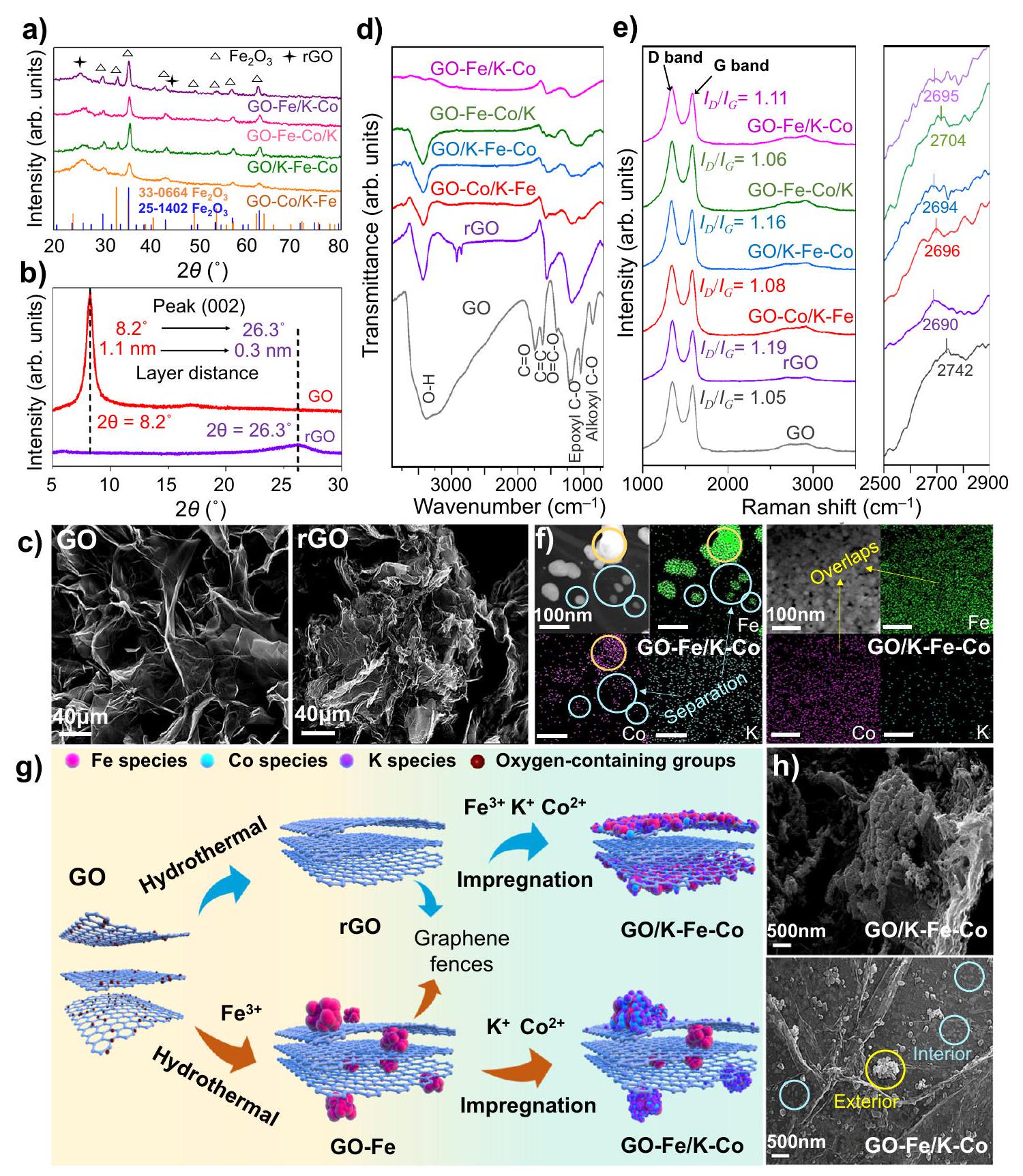
الشكل 1 | التحقيق في الهيكل والشكل لمرشحات FeCo المدعومة بالجرافين. أ أنماط XRD للمرشحات الجديدة.أنماط XRD لـ GO و rGO. ج صور SEM لـ GO و rGO؛ القضبان تمثل. طيف FTIR للمواد الحفازة الجديدة. e طيف رامان للمواد الحفازة الجديدة. f صور خرائط TEM لمواد GO-Fe/K-Co و GO/K-Fe-Co الحفازة؛ الأشرطة في الصور تمثل 100 نانومتر. الدوائر الصفراء تمثل مناطق التوزيع المتداخلة، بينما الدوائر الزرقاء الفاتحة تمثل مناطق الفصل. رسم تخطيطي لعمليات التحضير، والهياكل المكانية، وتوزيعات الأنواع لـ GO/K-Fe-Co و GO-Fe/K-Co. أنواع الحديد، كرات حمراء؛ أنواع الكوبالت، كرات زرقاء فاتحة؛أنواع، كرات بنفسجية.صور SEM لمحفزات GO/K-Fe-Co و GO-Fe/K-Co. الدوائر الزرقاء الفاتحة والصفراء تمثل المواقع المعدنية المفصولة بأسوار الجرافين. تم ملاحظة كل ذلك في طيف FTIR لـ GO. بعد التخليق الهيدروحراري، تم تقليل قمم المجموعات المحتوية على الأكسجين في rGO بشكل ملحوظ، وظهرت قمتان عريضتان عند و ظهرت، والتي تم تعيينها لـ و على التواليمن المثير للاهتمام أن قمم الاهتزاز في المحفزات المدعومة بالمعادن أظهرت مناطق أصغر مقارنة بتلك الخاصة بـ rGO، خاصة في GO-Fe/K-Co و GO-Fe-Co/K، مما يمكن تفسيره على أنه مزيد من استبدالات المجموعات المحتوية على الأكسجين بواسطة المعادن في عملية الاختزال، الناتجة عن تحميل المعادن على الطبقات الداخلية للجرافين. ومع ذلك، فإن المعادن في GO/ولم تتمكن GO-Co/K-Fe من استبدال المجموعات المحتوية على الأكسجين داخل الطبقات بشكل كافٍ بسبب حماية أسوار الجرافين، مما أدى إلى زيادة مساحة الذروة.
علاوة على ذلك، يمكن أن تكشف سماكة المحفزات الثنائية المعدن المدعومة بالجرافين من الحديد والكوبالت عن الهياكل المختلفة. تم الكشف عن سماكات الجرافين من خلال مواقع ذروة الرامان من الدرجة الثانية، التي تظهر بالقرب منبشكل عام، يمثل ارتفاع الذروة الأعلى سمك جرافين أكبر وعدد طبقات جرافين أكثر.أظهرت GO و rGO أقصى وأدنى سماكتين لطبقات الجرافين، على التوالي (الشكل 1e). مع إدخال الحديد والكوبالت، زادت سماكات الجرافين مقارنة بـ rGO، حيث كانت GO-Fe-Co/K هي الأكثر سماكة، مما يكشف أن وجود كل من الحديد والكوبالت في الطبقات الداخلية أعاق ضغط طبقات الجرافين خلال العملية الهيدروحرارية. كما تم الاستنتاج، GO/K-Fe-Co أظهر أقل سمك بين جميع المحفزات المدعومة بالجرافين.القيم المعروضة كانت بترتيب عكسي مقارنة بالسماكات، مما يشير إلى أن الاضطرابات زادت عندما تم ضغط سماكات الجرافين (الشكل 1e).
تمت الإشارة إلى التوزيعات المتفاوتة للحديد والكوبالت من خلال اختلاف محتويات المعادن بين السطح والداخل. استنادًا إلى نتائج XPS، كانت محتويات الحديد على السطح في GO-Co/K-Fe ( ) و ( كانت المحفزات التي تم إدخال الحديد فيها عن طريق النقع أعلى بشكل ملحوظ من تلك المحفزات التي تم تحميل الحديد فيها عن طريق الدمج الهيدروحراري، مثل GO-Fe-Co/K (3.4%) و GO-Fe/K-Co (4.1%) (الجدول التكميلي 3). في الوقت نفسه، فإن GO/مع محتوى أعلى من الحديد على السطح (الجدول التكميلي 3) أظهر شدة مغناطيسية أقوى فيالحلقة مقارنةً بـ GO-Fe/K (الشكل التوضيحي 5)، والتي دعمت لاحقًا الاستنتاج بأن الحديد المضاف من خلال العملية الهيدروحرارية كان محاطًا جزئيًا بطبقات الجرافين، مما أدى إلى انخفاض محتوى السطح وضعف شدة المغناطيسية. علاوة على ذلك، أظهرت قيم Fe/Co التي تم تصويرها بواسطة رسم الخرائط SEM، والتي عكست أيضًا محتويات العناصر السطحية، نفس الاتجاه كما تم قياسه بواسطة XPS (الشكل التوضيحي 6 والجدول التوضيحي 4). بالإضافة إلى توصيفات محتوى السطح، استخدمنا FIB-SEM للتحقيق مباشرة في توزيعات المعادن في الطبقات الداخلية للجرافين. في صور SEM المقطعية لـ GO-Fe/K-Co، وُجد أن جزيئات المعادن النانوية محملة بين طبقات الجرافين (الشكل التوضيحي 7a)، والتي تطابقت مع توزيعات رسم الخرائط للأكسيد والحديد (الشكل التوضيحي 7b، c)، بينما لوحظ فقط توزيع قليل من الكوبالت على الجزيئات المعدنية الداخلية (الشكل التوضيحي 7d). في الوقت نفسه، كانت قيمة Fe/Co للمقطع العرضي (8.42) التي تم الحصول عليها من رسم الخرائط SEM (الجدول التوضيحي 5) أعلى بكثير من تلك الخاصة بسطح المحفز (0.82) (الجدول التوضيحي 4). وقد أكدت التوزيعات المعدنية المختلفة على السطح والداخل بشكل فعال إعادة بناء المحفزات المدعومة بالجرافين، مما شكل هيكلًا فريدًا بتوزيعات مكانية مختلفة لمواقع نشطة متعددة.
بالإضافة إلى ذلك، كما هو موضح في الشكل 1f، أظهرت الدوائر الصفراء نفس توزيعات الحديد والكوبالت في GO-Fe/K-Co، بينما في الدوائر الحمراء تم ملاحظة توزيع الحديد بوضوح فقط. يمكن تفسير ذلك بصعوبة نقع الكوبالت في الطبقات الداخلية المطوية من الجرافين مقارنة بالحديد المحمّل عن طريق التخليق الهيدروحراري، مما يؤدي إلى تشكيل مواقع نشطة بتراكيب معدنية مختلفة. ونتيجة لذلك، تمثل الدوائر الصفراء والحمراء مواقع المعادن السطحية والداخلية في طبقات الجرافين، على التوالي. بالمقابل، الحديد والكوبالت في أظهر K-Fe-Co توزيعًا موحدًا وموزعًا بشكل جيد على السطح الخارجي لطبقات الجرافين (الشكل 1f). وقد أكدت هذه النتائج بشكل مقنع أن التوزيعات المكانية لمواقع النشاط Fe-Co يمكن تنظيمها بواسطة أسوار الجرافين، مما يشكل مواقع متناثرة. ) أو مواقع التجميع الموحدة (FeCo) (الشكل 1f).
استجابةً للوصف المذكور أعلاه، تم إعداد مخطط تفصيلي يوضح التطور الديناميكي فيما يتعلق بتخليقوتم رسم GO-Fe/K-Co في الشكل 1g. فيما يتعلق بمحفز GO/K-Fe-Co، تم تقليل GO أولاً من خلال عملية الهيدروحرارية، مما أدى إلى التواء وطي طبقات الجرافين، وبالتالي تشكيل أسوار جرافينية. بعد ذلك، تم دمج الحديد والكوبالت من خلال النقع وتوزيعهما بشكل أساسي على سطح أسوار الجرافين بتوزيع جيد، بسبب مقاومة الطبقات الداخلية المطوية. في حالة محفز GO-Fe/K-Co، تم إدخال الحديد خلال عملية الهيدروحرارية، مما سيحل محل المجموعات المحتوية على الأكسجين في الموقع ويكون محاطًا جزئيًا في الطبقات الداخلية للجرافين. ثم تم تحميل الكوبالت المنقوع على الطبقات الخارجية للجرافين بسبب الوصول غير المتاح الذي تتحكم فيه أسوار الجرافين، مما يشكل مواقع متفرقة مع كمية صغيرة من الحديد على السطح الخارجي لطبقات الجرافين. يمكن ملاحظة الهياكل المختلفة للتوزيع المكاني الموضحة أعلاه مباشرة من خلال صور SEM. الشكل 1h أظهر بوضوح مواقع نشطة متجانسة من Fe-Co مرتبة بشكل موحد على سطح طبقات الجرافين ( ) ومواقع المعادن مفصولة بأسوار من الجرافين ( )، حيث كان الدائرة الصفراء تمثل المواقع على الطبقة السطحية والدائرة الحمراء تمثل المواقع على الطبقة الداخلية. لذلك، مع مساعدة الأسوار المصنوعة من الجرافين، المدعومة بالجرافين تمت عملية تخليق المحفزات ثنائية المعدن ذات توزيعات معدنية قابلة للتعديل في الطبقات الداخلية والخارجية بنجاح.
خصائص تركيب الطور لـمحفزات
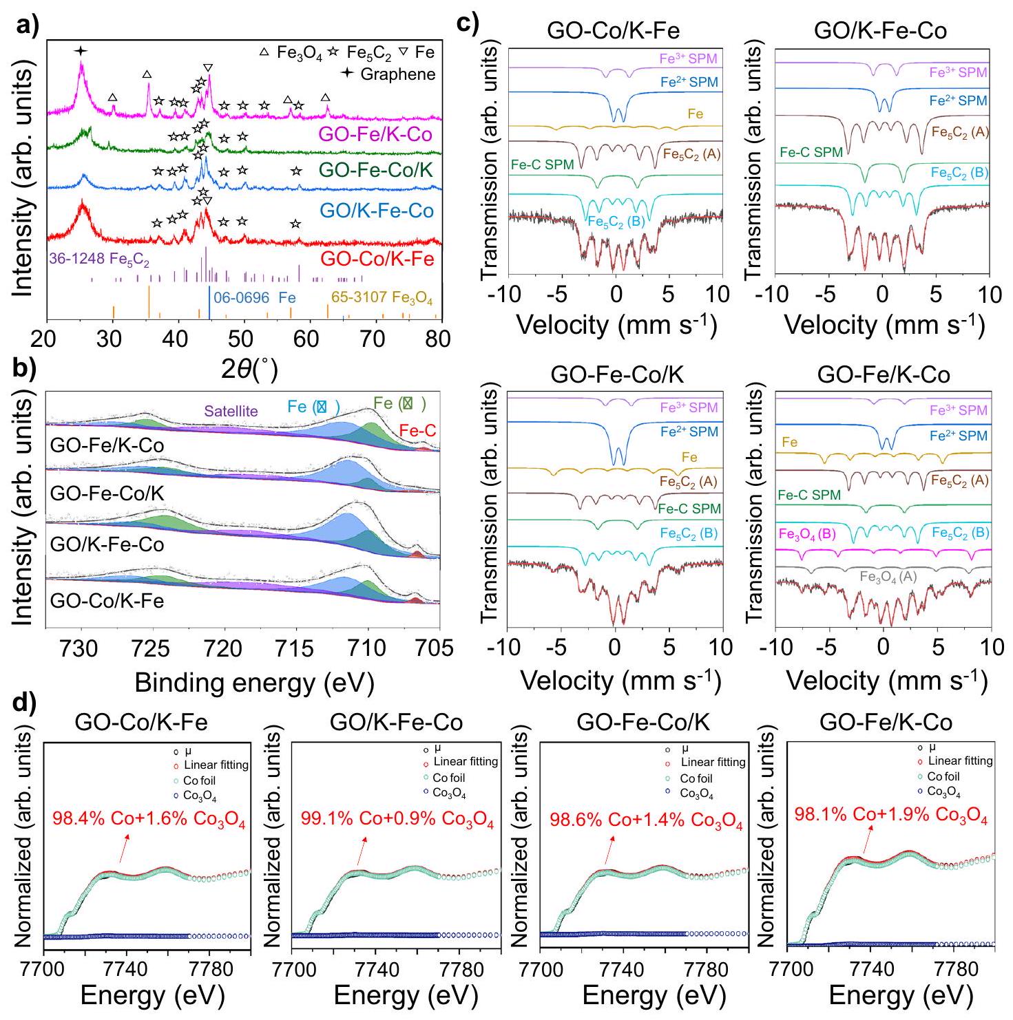
تم تطبيق عدة توصيفات أولاً لتحديد تركيبات الطور المعدني السطحي للمحفزات التي تم تحضيرها. كشفت صور HR-TEM (الشكل التكميلي 8) عن مسافات الشبكة البالغة 0.25 نانومتر التي تت correspond إلى المستوى (119) منالأنواع في المحفزات المدعومة بالجرافين الأربعة، والتي كانت متوافقة مع نتائج حيود الأشعة السينية الموضحة في الشكل.إكس بي إس الحديدأظهرت الأطياف (الشكل التوضيحي 9) قمم طاقة الربط عند 710.8 إلكترون فولت و712.8 إلكترون فولت، والتي تم نسبها إلى مراحل الحديد (II) والحديد (III) على التوالي.. علاوة على ذلك، وفقًا لـطيف ميسباور (الشكل التكميلي 10 والجدول التكميلي 6)، كان الحديد موجودًا بشكل أساسي في شكل، والتي كانت مزيجًا من و الأنواع. بسبب المحتويات المنخفضة أو التوزيعات الحميدة، لم تكن هناك قمم حيود تنسب إلى الكوبالت في أنماط حيود الأشعة السينية، في حين كانت هناك قمتان تنسبان إلى و ظهر في الشركةطيف XPS (الشكل التكميلي 11)لتحديد نسبة الكوبالت على السطح الحفاز بشكل أكبر، تم تسجيل طيف XANES مع منحنيات التناسب. كما هو موضح في الشكل التكميلي 12، تم تحديد CoO كمرحلة سائدة من أنواع الكوبالت بغض النظر عن توزيعاتها المكانية. بالإضافة إلى ذلك، تم عرض نتائج منحنيات التناسب لبيانات EXAFS عند حافة كوبالت والمعلمات في الشكل التكميلي 13 والجدول التكميلي 7، كاشفة عن وجود الـ و سندات.
فيما يتعلق بالعوامل المحفزة المستهلكة،أظهرت الأطياف قمم طاقة ربط عند 708.5 إلكترون فولت، والتي تم تعيينها لـ الروابط (الشكل 2ب)، مما يدل على وجود كربيدات الحديد . استنادًا إلى نتائج أنماط XRD، فإن القمم الانكسارية المنسوبة إلىتمت ملاحظتها في جميع المحفزات المستهلكة (الشكل 2أ). من بينها، كانت قمم الحيود ذات أقوى الشدات تت correspond إلى (510) وجهًا، والتي تم الكشف عنها أيضًا من خلال صور HR-TEM مع مسافات شبكية تبلغ 0.20 نانومتر (الشكل التكميلية 14) . علاوة على ذلك، فإن التعايش بين (أ) و تم تحديد النوع (B) من خلال مجموعتين متداخلتين من الستة.طيف ميسباور (الشكل 2c والجدول التكميلي 8)، الذي يمثل المواقع المختلفة المشغولة للحديد في الهيكل البلوري لـأظهرت النتائج المذكورة أعلاه أن كربيد الحديد، وهو مرحلة نشطة لتفاعل نمو السلسلة، كان موجودًا بشكل رئيسي كـالطور في المحفزات المستهلكةتم تطبيق اختبارات XANES على حافة الكوبالت (Co K-edge) أيضًا لتحديد مراحل الكوبالت في المحفزات المستهلكة. على عكس المحفزات المُعدة حديثًا، كانت الغالبية العظمى من الكوبالت موجودة في حالات معدنية (الشكل 2d)، مما يُظهر القدرات الجيدة للتقليل للكوبالت في المحفزات المدعومة بالجرافين. علاوة على ذلك، أوضحت نتائج تركيب EXAFS وجود فقط الروابط، مما يوفر دليلاً إضافياً على أن الكوبالت كان موجوداً في المراحل المعدنية (الشكل التكميلي 15 والجدول التكميلي 9).
أداء المحفزات والثبات
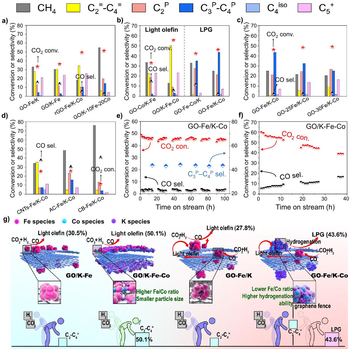
تم اختبار المحفزات تحت ظروف، و المنتجات الرئيسية لكل من المحفزات GO-Fe/K و GO/K-Fe، دون إضافة الكوبالت، كانت الميثان والأوليفينات الخفيفة بدلاً من البارافينات الخفيفة المشبعة (الشكل 3أ). ومع ذلك، كما هو موضح في الشكل 3ب، مع دمج الكوبالت، أظهرت المحفزات الثنائية المعدن Fe-Co أنواعًا مختلفة من انتقائية منتجات الهيدروكربونات. كانت GO-Co/K-Fe و GO/K-Fe-Co تنتج بشكل رئيسي أوليفينات خفيفة، خاصة بالنسبة لمحفز GO/K-Fe-Co، حيثتم الحصول على الانتقائية عندتحويل. بينما بالنسبة لـ GO-Fe-Co/K، تم إنتاج المزيد من الألكانات، وخاصة الميثان والإيثان (الشكل 3ب). ومع ذلك،
الشكل 2 | تركيبات الطور لمحفزات الحديد والكوبالت ثنائية المعدن المدعومة بالجرافين المستهلكة. أ أنماط حيود الأشعة السينية.فيطيف XPS. جطيف ميسباور. طيف XANES عند حافة كافيد الكوبالت مع منحنيات التوافق.
أظهر GO-Fe/K-Co انتقائية أعلى للبروبان والبيوتان ) مقارنة بـ GO-Fe-Co/K (الشكل 3ب). بالمقارنة مع GOتم تشكيل مواقع CoFe في GO-Fe/K-Co عن طريق نقع Co على مواقع Fe السطحية لـ بمساعدة أسوار الجرافين. تم استخدام GO/K-10Fe-20Co أيضًا لمحاكاة مواقع CoFe الخارجية لـ GO-Fe/K-Co التي كانت لها نسب سطحية مشابهة من Fe/Co (0.6 و 0.7) (الجدول التكميلي 3). أكدت الانتقائية العالية للميثان أن مواقع CoFe الخارجية ذات المحتوى العالي من Co كانت لديها قدرة قوية على الهدرجة (الشكل 3a)، مما سهل تحويل الأوليفينات الخفيفة الأصلية المنتجة على مواقع Fe الداخلية إلى ألكانات مشبعة، وبالتالي تحويل المنتجات من الأوليفينات الخفيفة إلى الغاز النفطي المسال (الشكل 3g). في هذه العملية، تم تحويل توازن التفاعل في الاتجاه الإيجابي، مما أدى إلى زيادة في التحويل من 33.2% (GO-Fe/K) إلى 46.0% (GO-Fe/K-Co). يمكن أيضًا ملاحظة ذلك في توزيعات المنتجات التفصيلية لـ GO-Fe/K و GO-Fe/K-Co (الشكل التكميلي 16). قبل إضافة الكوبالت، كانت انتقائية المنتج لـ C2 و C3 فيكان تقريبًا هو نفسه. ومع ذلك، بعد إدخالاحتلت المنتجات أعلى انتقائية، مما أشار بشكل أكبر إلى أن تأثيرات الانتشار والهدرجة على المنتجات ذات المواقع النشطة الداخلية قد حولت التوازن الكيميائي في اتجاه إيجابي.
على عكس GO-Fe/K-Co، كانت منتجات rGO-Fe/K-Co في الغالب أوليفينات خفيفة بدلاً من الألكانات (الشكل 3أ). وكان ذلك بسبب غياب المواقع النشطة المزدوجة المكانية المفصولة بواسطة أسوار الجرافين (الشكل التوضيحي 17)، والذي تم إثباته من خلال الشكل التوضيحي 18 (نفس توزيعات الحديد والكوبالت في صور رسم الخرائط العنصرية بتقنية TEM)، مما أدى إلى نسبة أعلى من الحديد إلى الكوبالت (الجدول التوضيحي 3)، وبالتالي ضعف قدرة الهدرجة. وقد أثبتت هذه النتيجة بشكل أكبر أن التوزيعات المكانية الفريدة لمواقع الحديد والكوبالت النشطة المزدوجة التي تم ضبطها بواسطة أسوار الجرافين يمكن أن تتحكم بكفاءة في أنواع المنتجات.
من خلال مقارنة صور TEM (الشكل If والأشكال التكميلية 19-21)، لاحظنا أن المحفزات الجديدة GO-Fe-Co/K و GO/K-Fe-Co قدمت أحجام جزيئات أصغر مقارنة بالمحفزات الأخرى، مما يشير إلى أن الإضافة المتزامنة للحديد والكوبالت قيدت تجمع جزيئات الحديد النانوية وعززت تشتت أنواع الحديد.الهدرجة هي تفاعل حساس هيكليًا، والتشتت الأعلى مفيد لتحسين قدرة الكربنة للحديد وبالتالي تعزيز الأداء التحفيزي (الشكل 3 ج).. كما هو موضح، وفقًا لـطيف ميسباور للمواد الحفازة المستهلكة (الشكل 2c والجدول التكميلي 8)، أظهر GO/K-Fe-Co أكبر نسبة منبما في ذلك كلا من (أ) و (ب). وبناءً عليه، أظهر GO/K-Fe-Co أيضًا أعلى
الشكل 3 | الأداء التحفيزي والثبات. أ-د الأداء التحفيزي للعوامل الحفازة؛ ظروف التفاعل:استقرارية GO-Fe/K-Co (e) و GO/K-Fe-Co (f). g تخطيطي رسوم بيانية للأسوار الجرافينية المنظمةالمواقع النشطة التي تتحكم في نوع المنتج. أنواع الحديد، كرات حمراء؛ أنواع الكوبالت، كرات زرقاء فاتحة؛أنواع، كرات بنفسجية. تمثل الشخصيات بألوان متنوعة مواقع نشطة متنوعة في الإطار. التحويل (55.4%) وانتقائية أوليفينات الضوء العالية نسبيًا (50.1%) (الشكل 3ب). ومع ذلك، أظهر المحفز GO-Fe-Co/K أعلى درجة حرارة للقمم في -TPR (ذروة ) و -TPD profiles (الأشكال التكميلية 22 و 23). يمكن تفسير هذه الظاهرة بحقيقة أن الجسيمات الأصغر ستدخل أو تخترق الطبقات البينية بسهولة أكبر خلال العملية الهيدروحرارية، وهو ما تم إثباته من خلال تحميلات المعادن السطحية الأصغر، كما هو موضح في الجدول التكميلية 3. ونتيجة لذلك، فإن جزيئات المعادن النانوية المغطاة بإحكام بطبقات الجرافين أظهرت تفاعل قوي بين المعدن والداعم (SMSI)، مما جعل عملية الاختزال والكربنة أكثر تحديًا.. تم توضيح هذا الرأي بشكل حدسي بواسطة حيود الأشعة السينية في الموقع. عندما ارتفعت درجة الحرارة إلىظهر قمة من الحديد المعدني على المحفز GO-Fe-Co/K. من الواضح أن هذه الدرجة كانت الأعلى بين جميع المحفزات. وبالمثل، في عملية الكربنة،كما أظهرت أدنى قوة ذروة لـ (الشكل التوضيحي 24). في غضون ذلك، أظهرت الأبحاث السابقة أن الامتصاص الكيميائي القوي لـلا يتم تحفيزه بسهولة للهدرجة، وتكون طبقة من أنواع الحديد على السطح ناتجة عن الامتصاص الكيميائي القوي لـقد يقلل من الأداء التحفيزي. وبالتالي، أدت هذه الأسباب إلى انخفاض طفيف المحتوى ( ) و تحويل GO-Fe-Co/K (42.1%) أفضل من تلك الخاصة بـ GO/K-Fe-Co (72% و 55.4%) (الشكل 3b والجدول التكميلي 8).
على عكس، أظهر محفز GO-Fe/K-Co تفاعلًا مناسبًا بين المعدن والداعم (MSI) وقوى الامتزاز (الشكل التكميلي 22 والشكل التكميلي 23)، مما يؤدي إلىتحويل يصل إلى (الشكل 3ب). نظرًا لأن الكوبالت كان غير نشط في تفاعل RWGS، الشركة المحيطة بـستستهلك الطبقات السطحية المزيد من ثاني أكسيد الكربون دون إنتاجه. وبناءً عليه، تم استخدام GO/K-10Fe-20Co لمحاكاة الخارجيالمواقع، أظهرت أيضًا انتقائية منخفضة لثاني أكسيد الكربون (2.7%). وقد انخفضت بشكل ملحوظ مقارنة بتلك الخاصة بـ GO-Fe/K (15.6%)، التي تتكون من مواقع نشطة من الحديد (الشكل 3أ). هذه النتيجة اقترحت أيضًا أن مواقع CoFe النشطة ذات نسبة الحديد/الكوبالت المنخفضة (0.82) (الجدول التكميلي 4) الموجودة على السطح الخارجي لـ GO-Fe/K-Co يمكن أن تستهلك ثاني أكسيد الكربون المنتج من مواقع الحديد الداخلية، مما يحافظ على انتقائية ثاني أكسيد الكربون عند مستوى منخفض. ونتيجة لذلك، أظهر GO-Fe/K-Co انتقائية منخفضة للغاية لثاني أكسيد الكربون (2.2%) بين جميع المحفزات (الشكل 3ب). على حد علمنا، هذه هي أدنى قيمة تم الإبلاغ عنها للطريق الحالي للوسط الميثانولي وكذلك مسار FTS المعدل (يرجى الرجوع إلى المحفزات المحتوية على الحديد). علاوة على ذلك، ترسب الكربون السميك وجود جزيئات معدنية من حولها سيقلل من النشاط التحفيزيويمكن ملاحظة هذه الظاهرة في صور TEM للمحفزات المستهلكة (الشكل التكميلي 14). من الواضح، كما تحدده خريطة TEM، أن نسبةفي المنفقكان أقل بكثير من غيره من المحفزات وGO-Co/K-Fe الجديد (الشكل التكميلي 25، الجدول التكميلي 10 والجدول التكميلي 11)، والذي يمكن تفسيره بالكمية الكبيرة من الكربون غير المتبلور المترسب على سطح مواقع الحديد مما يؤثر على تحديد محتويات العناصر. ونتيجة لذلك، أظهر مستوى منخفض نسبيًاالتحويل (32.8%) (الشكل 3ب).
للمزيد من التحقيق في تأثير كمية الحديد، تم تغيير المحتوى الكلي للحديد في محفزات GO-nFe/K-Co منإلىبشكل بديهي، مع زيادة محتوى الحديد، زادت انتقائية غاز البترول المسال ) انخفضت، بينما كانت انتقائية الأوليفينات الخفيفة ( ) و زادت المنتجات (الشكل 3ج)، مما يكشف أن الحديد الإضافي الذي تم إدخاله إلى الداخل والأسوار الخارجية من الجرافين أدى إلى تعزيز قدرة نمو سلسلة الكربون وكبح الهدرجة الثانوية للأوليفينات، على التوالي. بالإضافة إلى ذلك، لمقارنة أداء GO-Fe/K-Co مع مواد الكربون الأخرى (CNTs، AC، وCB) المدعومة، تم تنفيذ نفس إجراءات التحضير وكميات الإضافة لـ GO-Fe/K-Co. كانت انتقائيات LPG لـ AC-Fe/K-Co (15.8%) وCB-Fe/K-Co (3.9%) أقل بكثير من تلك الخاصة بـ GO-Fe/K-Co (43.6%) بسبب التكوين المفرط للمنتج الثانوي الميثان والإيثان. بالإضافة إلى ذلك، كانت المنتجات الرئيسية لـ CNTs-Fe/K-Co هي الأوليفينات الخفيفة (35.5%) بدلاً من الهيدروكربونات المشبعة (7.3%) (الشكل 3d). في الوقت نفسه، تم تحديد توزيعات المعادن لهذه المحفزات من خلال صور رسم الخرائط العنصرية باستخدام TEM (الشكل التكميلي 26). تم العثور على توزيعات الكوبالت في جميع مناطق توزيع الحديد في هذه المحفزات الثلاثة، مما يشير إلى أن هذه المواد الكربونية الثلاثة تفتقر إلى وظيفة فصل المعادن مثل الجرافين. هذه النتائج أظهرت بشكل أكبر الأداء المتفوق لمواقع النشاط المزدوج المفصولة بجرافين في تنظيم نمو سلسلة الكربون والهيدروجين الثانوي للأوليفينات.
قمنا بمزيد من التحقيق في استقرار GO-Fe/K-Co و GO/K-Fe-Co تحت ضغط 3.0 ميغاباسكال مع نسبة W/F منفي. لكو، الـانخفضت نسبة التحويل وزادت انتقائية أول أكسيد الكربون كمنتج ثانوي بشكل مستمر خلال 40 ساعة من التشغيل. بالمقابل، ظل GO-Fe/K-Co مستقرًا خلال اختبار الاستقرار الذي استمر 100 ساعة (الشكل 3e، f). ومن المثير للاهتمام، كما هو موضح في صور TEM (الشكل التكميلي 19a)، أن جزيئات المعادن في المحفز المستهلك GO/K-Fe-Co تجمعت بشكل كبير مقارنةً بالمحفز الجديد مع تمديد عملية التفاعل. على العكس، لم تتجمع جزيئات المعادن في GO-Fe/K-Co المستهلك، وظلت أحجام الجزيئات ضمن نطاق مستقر طوال التفاعل (الشكل التكميلي 19a) بفضل حماية أسوار الجرافين. وقد أظهرت الدراسات السابقة أن الجرافين المحمّل بجزيئات الحديد بواسطة الطريقة الهيدروحرارية له دور في تثبيت جزيئات الحديد.بالإضافة إلى نتائجنا الموضحة أعلاه، فإن سياج الجرافين الذي فصل المواقع النشطة المزدوجة في محفز GO-Fe/K-Co يمكن أن يحصر أيضًا تجميع جزيئات المعدن خلال التفاعل، مما يمنع التوقف عن النشاط ويحافظ على نشاط مرتفع (الشكل التكميلي 19b). بالإضافة إلى ذلك، تم اختبار صور رسم الخرائط TEM لمحفزات GO-Fe/K-Co المستهلكة لاستكشاف توزيعات الحديد والكوبالت بعد التفاعل، وتظهر الصور المكبرة في الشكل التكميلي 27. تمثل الدوائر الحمراء المنطقة ذات التوزيعات المختلفة للحديد والكوبالت (توزيعات واضحة للحديد ولكن القليل من توزيعات الكوبالت). كما لوحظ، بعد عملية التفاعل، لا يزال سياج الجرافين يحافظ على تأثير فصل مواقع الحديد والكوبالت النشطة.
الدراسات الميكانيكية
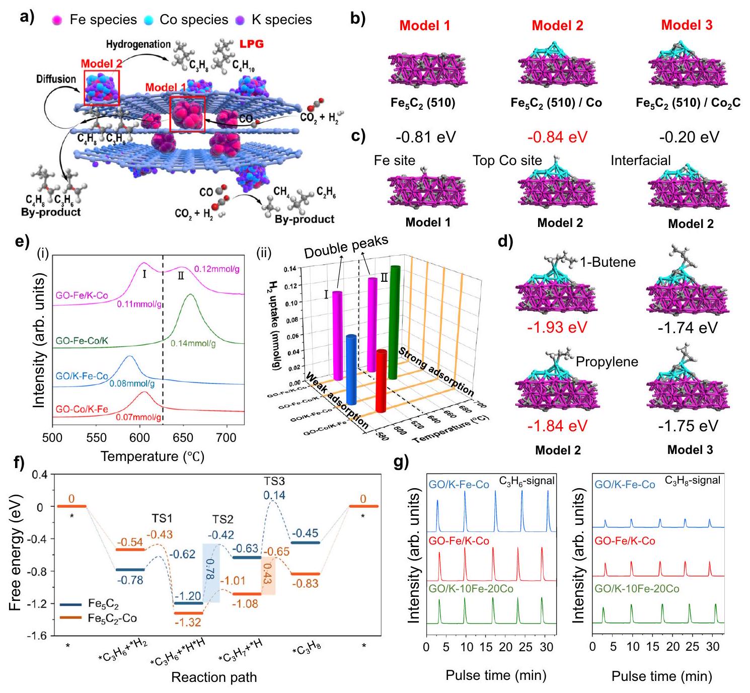
وفقًا للبيئات الدقيقة المحلية لمحفزات المعادن المدعومة المبلغ عنها في العمل السابقفي هذه الدراسة، استخدمنا حسابات نظرية الكثافة الوظيفية (DFT) لاستكشاف تأثير المواقع المزدوجة للحديد والكوبالت المفصولة بأسوار من الجرافين. لتحديد البيئة الدقيقة لكل موقع نشط بدقة، قمنا أولاً ببناء نموذج السطح (510)، الذي تم الإشارة إليه كنموذج 1. بعد ذلك، تم بناء نموذج 2 عن طريق إضافة العنقود إلى النموذج 1 مع الأخذ في الاعتبار دمج الكوبالت السطحي لـ GO-Fe/K-Co (الشكل 4b). حيث أن النموذج 1 يتوافق مع المواقع النشطة داخل أسوار الجرافين لـ GO-Fe/K-Co، في حين أن النموذج 2 يمثلالمواقع النشطة على سطح أسوار الجرافين (الشكل 4ب). من أجل مقارنة قدرات الامتصاص لكربيد الكوبالت والمعادن في النموذج 2 تم استبداله بـ ، وقد أطلق عليه اسم “النموذج 3” (الشكل 4ب). وفقًا لنتائج طاقة الامتزاز، فإن امتزاز كل من والأوليفينات الخفيفة على مواقع الكوبالت السطحية في النموذج 2 والنموذج 3 كانت أكثر استقرارًا من تلك الموجودة على المواقع البينية، مما يوضح أنوكانت الأوليفينات الخفيفة تُمتص بشكل أساسي على مواقع الكوبالت السطحيةبسبب انتقال الإلكترون بين كربيد الكوبالت والحديد (الشكل 4c و d، والشكل التكميلي 28). يمكن ملاحظة انتقال الإلكترون بين كربيد الحديد والكوبالت في النموذج 2 بشكل بديهي من خلال تحليل فرق كثافة الشحنة، كما هو موضح في الشكل التكميلي 29. تمثل الألوان الحمراء والخضراء تراكم الإلكترونات وفقدانها، على التوالي. من الواضح أنه بعد تحميله علىتم نقل الإلكترونات من الكوبالت إلىنظرًا لأن المعادن التي تعاني من نقص الإلكترونات تكون أكثر ملاءمة لامتصاص الهيدروجينكان نقل الإلكترون هو الذي عزز امتصاص الهيدروجين على موقع الكوبالت، بينما من غير المحتمل أن يتم امتصاص الهيدروجين على الواجهة.-بسبب تراكم الإلكترونات.
فيما يتعلق بامتصاص الهيدروجين، كان امتصاص الهيدروجين على النموذج 2، الذي تم امتصاصه على مواقع الكوبالت المعدنية على السطح، له طاقة امتصاص أقل (-0.84 eV) مقارنةً بالامتصاص على كربيد الحديد في النموذج.، كاشفًا أن المواقع على الأسوار الخارجية من الجرافين كانت أقوى تأثير الامتزاز أكثر من المواقع داخل أسوار الجرافين (الشكل 4c). وبناءً عليه،ملف إزالة الحرارة المبرمجة-TPD) من GO-Fe/K-Co أظهر ذروتين متميزتين (I و II) (الشكل 4e)، والتي تت correspond إلى الامتصاص الكيميائي الضعيف والامتصاص الكيميائي القوي للهيدروجين، على التوالي. عرض rGO-Fe/K-Co ذروة انبعاث بالقرب منيشبه ذلك لـ GO-Fe/K-Co. ومع ذلك، على عكس GO-Fe/K-Co، فإن ذروة الامتصاص الكيميائي القوية حوللم يكن واضحًا (الشكل التوضيحي 30)، وكان ذلك لأن التخفيض الجزئي لـ rGO-Fe/K-Co قد تم بالفعل عند إدخال الحديد، مما جعل سياجات الجرافين غير فعالة في تقسيم المواقع النشطة المزدوجة. علاوة على ذلك، عرض المحفز GO-Fe/K أيضًا قمة ضعيفة واحدة لامتصاص الهيدروجين الكيميائي قبل إضافة الكوبالت (الشكل التوضيحي 30). هذه الأدلة أثبتت بقوة أن هناك اختلافات في قدرات امتصاص الهيدروجين بين الداخليةالمواقع والسطحالمواقع بعد إضافة الكوبالت كانت الأسباب الرئيسية لتشكيل قمم إزالة الهيدروجين المختلفة لـ GO-Fe/K-Co في-TPD. حيثتوافق مع قمة الامتصاص الكيميائي الضعيف للهيدروجين (القمة I)، بينمايتوافق مع ذروة امتصاص الهيدروجين الكيميائي القوي (الذروة II) (الشكل 4ب، ج، و هـ).
في هذه الأثناء، قدمت GO-Co/K-Fe ذروة واحدة في -TPD الملف أيضًا، والذي يمكن تفسيره بحقيقة أن كمية كبيرة من الحديد تم تحميلها على سطح الكوبالت المعدني، مما يمنع امتصاص الهيدروجين على مواقع الكوبالت. علاوة على ذلك، تم توزيع الحديد والكوبالت بشكل متساوٍ ومضغوط على أسوار الجرافين في GO-Fe-Co/K ونظرًا لإضافتها المتزامنة، فقد قدمت أيضًا قمة كيميائية واحدة (الشكل 4e). من بينها، أظهر GO-FeCo/K أعلى حالات تكافؤ الكوبالت في نتائج XANES (الشكل التكميلي 12)، مما يشير إلى أن الكوبالت فقد أكبر عدد من الإلكترونات في GO-Fe-Co/K، بينما أظهر GO-Fe/K-Co، الذي كان الكوبالت مدعومًا على سطح الحديد، أدنى حالات تكافؤ (الشكل التكميلي 12)، وهو ما يمكن تفسيره على أنه التفاعل القوي بين المعدن والداعم في GO-Fe-Co/K الذي يعزز انتقال الإلكترونات بين الكوبالت والجرافين (الشكل التكميلي 22). وقد كشفت الدراسات السابقة أن المعادن التي تعاني من نقص في الإلكترونات تكون أكثر عرضة لامتصاص الهيدروجين.. لذلك، عرض GO-Fe-Co/K أقوى قمة لامتصاص الهيدروجين. على العكس، أظهر GO/K-Fe-Co، الذي تم تحميله بالحديد والكوبالت عن طريق النقع، قمة أضعف لامتصاص الهيدروجين
الشكل 4 | استكشاف آلية التفاعل والمسار. أ مخطط مسار التفاعل. أنواع الحديد، كرات حمراء؛ أنواع الكوبالت، كرات زرقاء فاتحة؛ أنواع البوتاسيوم، كرات بنفسجية. ب نماذج حساب DFT لـ، و ألوان الركيزة: الحديد، وردي؛ الكربون، بني؛ الكوبالت، أزرق.نماذج الامتزاز وطاقة الامتزاز على و نماذج. ألوان الركيزة: الحديد، وردي؛ الكربون، بني؛ الكوبالت، أزرق؛ الهيدروجين، أبيض. نماذج امتصاص البروبلين و1-بيوتين وطاقة الامتصاص فوق /
كو ونماذج. هـ-ملف TPD (i) وثلاثي الأبعاد-رسم تخطيطي TPD (ii). f DFT المحسوبة لمسار التفاعل التحفيزي المقترح لهدرجة البروبينموقع-موقع Co في ظروفتظهر طاقات التفاعل الحرة (eV) في الزاوية. الأجزاء المظللة تمثل حواجز الطاقة للخطوة المحددة للسرعة.-ملفات الهيدروجين المؤقتة للنبضات المحفزات المستهلكة (إشارةإشارة). (الشكل 4e) بسبب التفاعل الأضعف بين المعدن والدعم (الشكل التوضيحي 22) وعدد أقل من نقل الإلكترونات بين المعادن والجرافين (الشكل التوضيحي 12). بالإضافة إلى ذلك،تم إجراء اختبار TPD على أكسيد الجرافين (GO) لاستبعاد تأثير تحلل مادة الكربون. لم تُلاحظ أي قمم واضحة في الملف، مما يشير إلى أن GO ظل مستقرًا في جو الهيليوم. (الشكل التوضيحي 31).
كانت هذه الخصائص لامتصاص الهيدروجين (الشكل 4e) متوافقة مع الأداء التحفيزي (الشكل 3b): كان الهيدروجين الملتصق بشكل ضعيف أسهل في التفعيل وبالتالي أكثر ميلاً للهيدروجين.لتمديد سلاسل الكربون أكثر من الهيدروجين الثانوي للأوليفينات، مما يؤدي إلى توليد المزيد من الأوليفينات. وبالتالي، كانت المنتجات الأولية لـ GO/K-Fe-Co و GO-Co/K-Fe هي الأوليفينات الخفيفة (الأشكال 3ب و 4هـ). من بينها، أظهر GO/K-Fe-Co مستوى أعلى منالانتقائية (50.1%) (الشكل 3ب) بسبب موقع ذروة الامتصاص الأدنى (الشكل 4هـ). على العكس من ذلك، تم امتصاصه بشكل كيميائي قويالذي لم يتم تفعيله، كان يميل إلى هدرجة الأوليفينات لإنتاج الألكانات، لذلك أنتج GO-Fe-Co/K المزيد من البرافينات، وخاصة الميثان والإيثان (الشكل 3ب). ومع ذلك، على عكس المحفزات الأخرى، قدم GO-Fe/K-Co قمم مزدوجة في -ملف TPD (الشكل 4e) ، أظهر أن كل من قدرة نمو سلسلة الكربون وقدرة الهدرجة الثانوية للأوليفينات قد تم تحقيقها كما ذُكر أعلاه. ونتيجة لذلك، على عكسالتي كانت منتجاتها الرئيسية الميثان والإيثان، تم توسيع وتركيز المنتجات في GO-Fe/K-Co لتكون البروبان والبيوتان. ) (الشكل 3ب).
من أجل التحقق بوضوح من الفروق في صعوبات تفاعل هدرجة الأوليفينات على المواقع النشطة المزدوجة المكانية، تم إجراء حسابات DFT لمسارات التفاعل المحتملة والوسطاء لهدرجة البروبلين إلى البروبان استنادًا إلى هياكل النموذج 1 والنموذج 2 التي تم بناؤها أعلاه، وتم تلخيصها (الشكل 4f، الأشكال التكميلية 32 و33).المواقع اللازمة لتجاوز حاجز الطاقة البالغ 0.78 إلكترون فولت لتحويلمتوسط إلى. ومع ذلك، بالنسبة لـ الموقع، تم تغيير الخطوة المحددة لتقييم العملية بأكملها إلى خطوةإلىحاجز الطاقة المحدد بمعدل أقل (0.43 إلكترون فولت) لـالموقع أشار إلى نشاط أعلى في هدرجة البروبلين مقارنة بـالموقع (الشكل 4f). بالإضافة إلى ذلك،تجارب الهيدروجين المتقطعة بالنبض التي أجريت على المواد المستهلكةتم تطبيق محفزات GO/K-10Fe-20Co لفحص قدرات الهدرجة الثانوية للبروبيلين بشكل واقعي على
الشكل 5 | المسار المصمم لفيشر-تروبش لـالهدرجة إلى الغاز النفطي المسال. تأثير تآزري لموقعين نشطين مزدوجين لإنتاج الغاز النفطي المسال منالهدرجة. تمثل الأرقام حواجز الطاقة الحرة (eV). حسابات DFT من b-c للسلسلة
تفاعلات النمو والهدرجة الأليفينية من الإيثيلين إلى البروبان علىالموقع (ب) و-موقع Co (c). الكرات الحمراء والزرقاء تمثل أنواع الحديد والكوبالت، على التوالي. مواقع نشطة مختلفة. كما تم حسابه بواسطة DFT، بنفس الكمية منتم ضخها في المفاعل، أظهرت GO-Fe/K-Co مستوى أعلىإشارة مقارنة بـ GO/K-Fe-Co، التي أظهرت قدرة أقوى على هدرجة البروبلين الثانوية. علاوة على ذلك، GO/Kأظهر أعلىإشارة، وكشفت هذه النتيجة أيضًا أن الخارجيكانت المواقع هي المواقع النشطة الرئيسية لتفاعل هدرجة البروبلين للحصول على البروبان (الشكل 4g). لم نجد قمم نبضية تعزى إلى إشارة الميثان في المحفزات الثلاثة المستهلكة (الشكل التكميلية 34)، مما يوضح أنه لم يحدث تفاعل تكسير هيدروجيني.
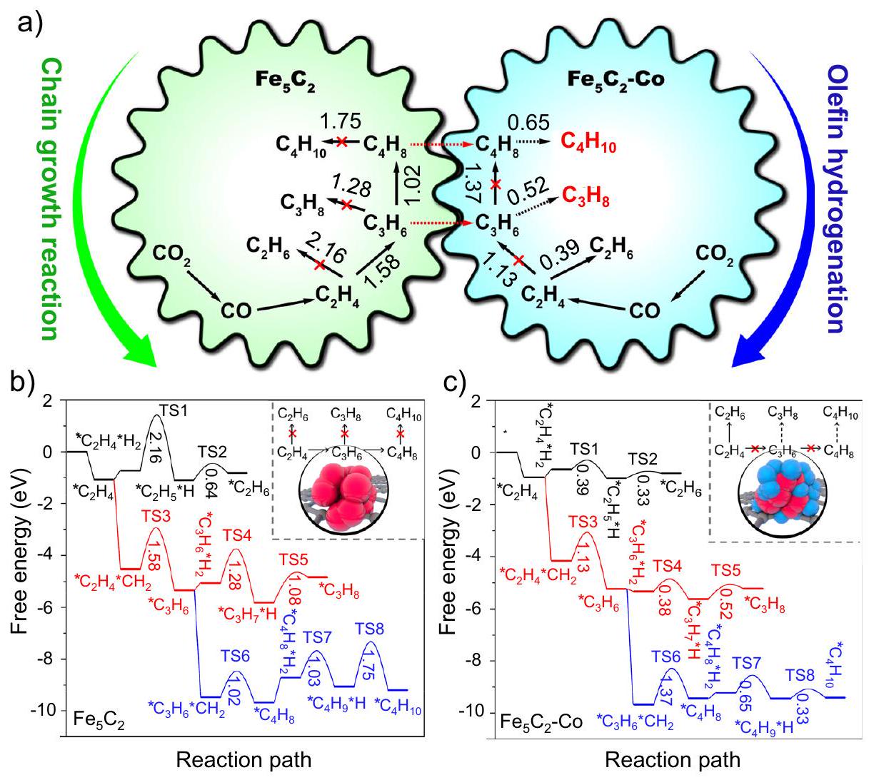
نتيجة لذلك، مسار تفاعل للاختياريةتم اقتراح الهدرجة على المحفز GO-Fe/K-Co في الشكل 4a من خلال تحليل نتائج التفاعل وخصائص الآلية. في البداية،تم تحويله إلى CO عبر تفاعل RWGS في مواقع النشاط الداخلية للحديد، تلاه عملية FTS لإنتاج الأوليفينات الخفيفة. يمكن أن تؤدي تأثيرات الانتشار بسهولة إلى نقل الأوليفينات الخفيفة إلى مواقع CoFe النشطة على السطح الخارجي للأسوار الجرافينية، حيث كانت مواقع CoFe تحتوي على نسبة عالية نسبيًا من الكوبالت. نظرًا لقدرتها الأعلى على امتصاص الهيدروجين، تم هدرجة الأوليفينات إلى الألكانات الخفيفة، مما أدى إلى تحقيق انتقائية عالية للغاز البترولي المسال (LPG). ومن الجدير بالذكر أن قوى الامتصاص للبروبين و1-بيوتين الممتصين على السطح المعدني للكوبالت في النموذج 2 كانت أقوى من تلك الممتصة علىفي النموذج 3 (الشكل 4d)، مما يؤكد كفاءة أعلى في هدرجة الأوليفينات للكوبيوم المعدني مقارنةً بـفي هذا الفريدنظام تفاعل الهدرجة. في الوقت نفسه، بسبب عدم نشاط الكوبالت في تفاعل RWGS، فإن الكوبالت المحمّل على السطح الخارجي سيستهلك كمية كبيرة من أول أكسيد الكربون الناتج عن مواقع الحديد النشطة الداخلية، مما يؤدي إلى اختيارية منخفضة للغاية لأحادي أكسيد الكربون (2.2%). ومع ذلك، فإن العاليالتركيز الناتج عن نقص تفاعل RWGS أجبرالهدرجة مباشرة إلى المنتجات الثانوية الميثان والإيثان فيالمواقع على السطح الخارجي للأسوار الجرافينية، كما الذي تم إثباته من خلال الأداء التحفيزي لـ GO/K-10Fe-20Co (الشكل 3أ).
من أجل استكشاف التأثير التآزري للمواقع النشطة المزدوجة بوضوح في عملية التفاعل، قمنا بإجراء حسابات DFT لتفاعلات نمو السلسلة وهدرجة الأوليفينات من الإيثيلين إلى البوتان على و -مواقع Co (الشكل 5، الأشكال التكميلية 35-37). في الموقع، من المرجح أن تخضع الألكينات لـتفاعلات الاقتران لتحقيق نمو سلسلة الكربون أكثر من تفاعلات الهدرجة الثانوية بسبب حواجز الطاقة الحرة الأقل. لذلك، سيتم الحصول على المزيد من الألكينات طويلة السلسلة.في الموقع، فإن هدرجة الألكينات إلى ألكانات أسهل من تفاعل نمو السلسلة، لذا سيكون هناك المزيد من الإيثان مقارنة بالبروبان والبيوتان المنتجين. ومع ذلك، بمجرد أن تنتشر منتجات البروبلين والبيوتين منالمواقع إلى-مواقع Co، بسبب الحواجز الطاقية المنخفضة لتفاعلات هدرجة البروبلين والبيوتين (0.52 و0.65 إلكترون فولت)، سيكون من السهل هدرجة البروبلين والبيوتين إلى بروبان وبيوتان، مما يؤدي إلى انتقائية عالية لمنتجات الغاز البترولي المسال.
كشفت هذه النتائج الحسابية أيضًا عن صعوبة إنتاج الغاز البترولي المسال منالهدرجة عبر مسار فيشر-تروبش، أي التناقض بين نمو سلسلة الكربون والهدرجة الثانوية للأوليفينات. بالنسبة للمواقع النشطة ذات القدرة الضعيفة على امتصاص الهيدروجين، مثل، من الصعب هدرجة الألكينات إلى ألكانات، مما يؤدي إلى انخفاض انتقائية الألكان. بينما بالنسبة للمواقع ذات القدرة العالية على امتصاص الهيدروجين، مثلمن ناحية أخرى، من الصعب أيضًا تحقيق نمو الكربون، وتؤدي المنتجات الزائدة من الميثان والإيثان إلى تقليل انتقائية الغاز البترولي المسال (الشكل 4c و5). في هذه الحالة، يمكن أن تلبي المواقع النشطة المزدوجة المقترحة المفصولة بواسطة الجرافين المتطلبات الخاصة بنمو سلسلة الكربون وهدرجة الأوليفينات في الوقت نفسه، وبالتالي التغلب على هذه الصعوبة.
كما تم تلخيصه أعلاه، كعامل مساعد لإنتاج الأوليفينات، كان لدى GO/K-Fe-Co سطح يحتوي على عدد كبير من مواقع الكربيد الحديدي النشطة مع عدد قليل من مواقع الكوبالت المعدنية. الاتصال الوثيق (الشكل 1f) وانتقالات الإلكترون بين الحديد والكوبالت تجعل قدرة امتصاص الهيدروجين لديهم تميل إلى أن تكون متجانسة. في الوقت نفسه، بسبب نقص تأثيرات الفصل، فإن السطح الأعلىالقيمة (الجدول التكميلي 3) قللت أيضًا من قدرتها على امتصاص الهيدروجين. من الواضح أن GO/K-Fe-Co لم يظهر قمة قوية لامتصاص الهيدروجين الكيميائي (الشكل 4e) في ظل نسبة عالية من Fe/Co على السطح (الجدول التكميلي 3). علاوة على ذلك، كما لوحظ في صور TEM (الشكل 1f)، كان البوتاسيوم موزعًا بشكل موحد على الجسيمات النانوية من الحديد والكوبالت بسبب التشتت الجيد. لقد ثبت أن البوتاسيوم يعيق الامتصاص الكيميائي وزيادة انتقائية الأوليفيناتوبالتالي، دون مساعدة أسوار الجرافين، كانت الأوليفينات الخفيفة المتكونة تنتشر بسهولة في تدفق الغاز وتخرج بسبب القدرات الضعيفة للهيدروجين الثانوي للأوليفينات (الشكل 4e)، وأظهرت انتقائية أعلى للأوليفينات الخفيفة (50.1%) (الشكل 3b).
نقاش
باختصار، تنظيم السياج الجرافينيتم تحضير واستخدام المحفزات ثنائية المعدن ذات المواقع النشطة المتجانسة أو المواقع النشطة المزدوجة الموزعة بنجاح فيتفاعل الهدرجة للإنتاج الانتقائي للأوليفينات الخفيفة أو الغاز النفطي المسال دون أي معالجات لاحقة. وصل المحفز GO/K-Fe-Co، بتوزيعه المتجانس وأحجام جزيئاته الأصغر، إلىانتقائية تصل إلىفيتحويل. بينما أظهر المحفز GO-Fe/K-Co المفصول بواسطة سياج الجرافين اختيارية بنسبة 43.6% للغاز النفطي المسال (البروبان والبيوتان) واختيارية منخفضة للغاية لثاني أكسيد الكربون بنسبة 2.2% عند 46% التحويل دون مساعدة أي زيولايت. كانت نتيجة هذه التفاعل تتوافق مع أعلى معدل إنتاجية (STY) ) من غاز البترول المسال (LPG) الذي تم الإبلاغ عنه على الإطلاق. أظهرت نتائج التوصيف والحسابات النظرية أن المواقع النشطة المزدوجة (كربيدات الحديد وكوبالت معدني) أدت وظائفها المصممة خصيصًا، مما يلبي في الوقت نفسه متطلبات نمو سلسلة الكربون المناسبة والهيدروجين الثانوي للأوليفينات، ويعمل على تحسين انتقائية غاز البترول المسال بشكل انتقائي. علاوة على ذلك، منعت أسوار الجرافين جزيئات المعدن من التكتل، مما عزز الاستقرار التحفيزي. نتوقع أن تلهم هذه الطريقة المتطورة في استغلال الهيكل المحدد للجرافين لصنع محفزات ذات مواقع نشطة متعددة تفاعلات تحفيزية مهمة أخرى. أخيرًا، لا توفر هذه الدراسة محفزًا ذا مواقع نشطة متعددة مع توزيع مكاني فريد من نوعه من أجل الانتقائية الهدرجة ولكنها توفر أيضًا فهمًا أساسيًا لدور أسوار الجرافين في الهدرجة الانتقائية. يمكن توسيعها لتشمل محفزات مدعومة أخرى وتقدم إرشادات قيمة لتصميم بيئات تفاعل قوية من خلال هندسة التوزيعات المكانية لمواقع النشاط المختلفة.
طرق
تحضير المحفز
أكسيد الجرافين (GO). (7.5 جرام، شركة رينت للمواد الكيميائية.) وتم إضافة شركة داماو للمواد الكيميائية إلى دورق دائري القاع تحت ظروف حمام مائي ثم تم دمجه مع المركز (شركة فوشين للمواد الكيميائية) عن طريق التحريك لمدة 15 دقيقة. ثم أضيف مسحوق الجرافيت (10 جرام، شركة سينوفارم للمواد الكيميائية) إلى المحلول. بعد التحريك لمدة 4.5 ساعة، تم تصفية الخليط وشطفه حتى وصل الرقم الهيدروجيني للمحلول العلوي إلى 7، قبل أن يتم تجفيفه طوال الليل. ثم تم نقل الجرافيت المجفف المؤكسد مسبقًا إلى دورق ثلاثي الرقبة مع مركز.في حمام من الماء المثلج. تحت الظروف المذكورة أعلاه،تم إضافة شركة سينوفارم للمواد الكيميائية في هذه مراحل التحضير. تم تحريك المحلول فيلمدة 3 ساعات قبل أن يتم دمجه تدريجياً مع الماء المنزوع الأيونات وحتى لا تحدث فقاعات، ثم تم تركه ليلاً. تم نقل المعلق السفلي من المحلول إلى الـ (فوشين
شركة المواد الكيميائية) لعلاج التحمض. بعد الترشيح والغسل حتى الوصول إلى الحيادية، تم نقل أكسيد الجرافين إلى الماء المنزوع الأيونات وتم تحريكه بالموجات فوق الصوتية لمدة 5 ساعات. أخيرًا، تم الحصول على أكسيد الجرافين المجفف باستخدام طريقة التجفيف بالتجميد.
محفزات ثنائية المعدن من الحديد والكوبالت مدعومة بالجرافين. تم تصنيع محفزات ثنائية المعدن K-Fe-Co المدعومة بالجرافين باستخدام طريقة التخليق الهيدروحراري في وعاء واحد والتشبع. كانت الأحمال المستهدفة للمحفزات المحضرة هي، و تمت دراسة مكونات المحفزات الناتجة بواسطة اختبارات مطياف الانبعاث الضوئي البلازمي المقترن بالحث (ICP-OES)، وتظهر النتائج في الجدول التكميلي 1.
بالتفصيل، GO (2.0 جرام)، اليوريا (2.0 جرام، شركة سينوفارم للمواد الكيميائية).تم إذابة (شركة داماو للمواد الكيميائية) في خليط من الإيثيلين غليكول (40 مل، شركة هينغشينغ للمواد الكيميائية) والماء المقطر (290 مل) ثم تم تحريكه وتعريضه للموجات فوق الصوتية لمدة ساعتين. تم نقل السائل الناتج إلى وعاء ضغط من الفولاذ المقاوم للصدأ مبطن بتفلون، تلاه تخليق هيدروحراري في وعاء واحد عندلمدة 12 ساعة مع دوران. تم غسل المنتجات وترشيحها حتى تصبح محايدة، ثم تم تجميدها لتجفيفها قبل التكلس عندفي جو من النيتروجين لمدة 4 ساعات (ما لم يُذكر خلاف ذلك، كانت جميع طرق التجفيف المستخدمة هي طرق التجفيف بالتجميد للحفاظ على هيكل الجرافين). تم تحميل الكوبالت والبوتاسيوم عن طريق النقع (شركة ماكلين للكيماويات الحيوية) و (شركة دماو للمواد الكيميائية) كمصادر للكوبالت والبوتاسيوم، على التوالي. تم حساب كمية المادة الم impregnated وفقًا للمحتويات المعطاة. تم تجفيف المحفز الناتج وتكلسه فيفي جو من النيتروجين لمدة 4 ساعات. تم تسمية المحفز الذي تم تحضيره باسم GO-Fe/K-Co. يجب ملاحظة أن الجزء قبل الشريط يمثل العناصر المحملة بطريقة الهيدروحرارية ذات الوعاء الواحد، بينما الجزء بعد الشريط يمثل العناصر المحملة بطريقة النقع. تم التحضير بالخطوات التالية: تم إجراء معالجة مائية حرارية لـ GO واليوريا أولاً، تلتها عملية نقع، و كـ، وتقوم Co بتوريد المواد إلى المحفز المحروق. ظلت عمليات التجفيف والتكلس بعد التخليق الهيدروحراري والتشريب دون تغيير.
بنفس الطريقة، تم تخليق محفزات GO-Co/K-Fe و GO-Fe-Co/K بالتحميلات المعطاة من خلال تغيير ترتيب إضافة المواد عبر الطرق الهيدروحرارية أو طرق النقع دون تغيير أي تقنيات أو مراحل تحضير أخرى.
لفحص تأثير محتويات الحديد،مع تحميلات الحديد المستهدفة من و تم تحضيرها وتحديدها على أنها GO-25Fe/KCo وGO-30Fe/K-Co، على التوالي. بالإضافة إلى ذلك، تم تخليق GO/K-10Fe-20Co عن طريق تحميل و تمت عملية التحميل باستخدام عملية النقع. على عكس المحفز GO/K-Fe-Co المذكور أعلاه، تم أولاً نقع الحديد على سطح الجرافين، ثم تم تحميل الكوبالت.
محفزات الحديد المدعومة بالجرافين. تم تصنيع محفزات GO-Fe/K و GO/K-Fe بدون إضافة الكوبالت، حيث كانت الأحمال للحديد والبوتاسيوم و ، على التوالي.
مواد كربونية أخرى مدعومةالمحفزات ثنائية المعدن. من خلال إضافة كميات متساوية من، و لأغراض المقارنة مع تلك الخاصة بمحفز GO-Fe/K-Co، تم استخدام أنابيب الكربون النانوية (CNTs، شركة ماكلين للكيماويات الحيوية)، والكربون الأسود (CB، شركة ماكلين للكيماويات الحيوية)، والفحم النشط (AC، شركة داماو للكيماويات) كدعائم لتحضيرالمحفزات ثنائية المعدن. تم تسمية هذه المحفزات على أنها CNTs-Fe/K-Co و CB-Fe/K-Co و AC، على التوالي. تم إذابة فقط GO (2.0 جرام) واليوريا (2.0 جرام) في خليط من الإيثيلين جلايكول (40 مل) والماء المقطر (290 مل)، وتم تحريكه، ونقله إلى وعاء ضغط من الفولاذ المقاوم للصدأ مبطن بتفلون، حيث تم إجراء التخليق الهيدروحراري في وعاء واحد لمدة 12 ساعة فيتم غسل المادة الناتجة وتجفيفها وتحميصها، وتم تصنيف الجرافين الناتج على أنه rGO. rGO-Fe/K-Co. تم تطبيق نفس عملية التخليق المستخدمة في GO-Fe/K-Co على تخليق rGO-Fe/K-Co، ولكن المادة الخام كانت rGO.
توصيف
إجمالي التحميلات الفعلية لـ، وتم تحديد K في المحفزات المختلفة باستخدام ICP-OES، الذي تم إجراؤه على جهاز Agilent 5110 (OES). كانت إجراءات الاختبار كما يلي: تم إذابة عينة بوزن 10 ملغ في محلول مختلط ( ) بين عشية وضحاها. ثم أضيفت العينة المذابة إلى دورق وتم تخفيفها إلى خط القياس. تم إعداد خمس حلول معيارية داخلية بتركيزات مختلفة ( ، ، و تم تحليل ( )، وتم تشكيل منحنى قياسي.
للحصول على أنماط الحيود، تم استخدام جهاز حيود الأشعة السينية (XRD) معتم استخدام الإشعاع على جهاز ريغاكيو RINT 2400 (زاوية المسح: ; سرعة المسح: ؛ الجهد والتيار: 40 كيلو فولت و 40 مللي أمبير). تم إجراء قياس XRD في الموقع على نظام حيود SmartLab-TD باستخداممصدر مع سخان XRK 900. تم إجراء التخفيض تحت ظروف الهيدروجين النقي ونطاق درجة حرارةتم تنفيذ عملية الكربنة على غاز التفاعل ( ) في تم فحص أشكال السطح للمحفزات باستخدام المجهر الإلكتروني الماسح (SEM، JEOL JSM-IT700HR)، وتم استخدام المجهر الإلكتروني الناقل (TEM، JEOL JEM-2100F) لمراقبة الأشكال ورسم الخرائط العنصرية للمحفزات عند جهد تسريع قدره 100 كيلوفولت. تم إجراء SEM باستخدام شعاع أيوني مركّز (FIB) باستخدام مجهر إلكتروني مزدوج الشعاع (Helios G4 PFIB CXe). تم تحديد مساحة سطح المحفزات باستخدامتجارب الامتزاز-إزالة الامتزاز عند (ميكروميريتكس 3فليكس ASAP 2460). قبل الاختبارات، تم تفريغ العينات من الهواء تحت الفراغ لمدة 8 ساعات في . الـتم قياس خصائص المحفزات الطازجة باستخدام مقياس مغناطيسي عينة مهتزة (VSM، LakeShore 7404). الاختزال المبرمج بالحرارةتم إجراء اختبارات (TPR) باستخدام محلل BELCAT-II-T-SP مع كاشف الموصلية الحرارية (TCD). تم استخدام الهيليوم كغاز معالجة مسبقة لعينة وزنها 30 ملغ لمدة ساعة واحدة عندخليط غازي ( ) تم تسليمه بعد ذلك إلى المفاعل بمعدل عندما تم خفض درجة الحرارة إلى. أخيرًا، -تم الحصول على منحنيات TPR عند درجات حرارة تتراوح من 50 إلىمعدل تسخين قدره في الدقيقة. أو تمت دراسة اختبارات إزالة الحرارة المبرمجة (TPD) أيضًا باستخدام نفس الجهاز. تم تقليل 30 ملغ من العينة لمدة ساعتين عندتحتتدفق الغاز ). تم خفض درجة حرارة المفاعل إلى تحت تدفق غاز الهيليوم ) بعد التخفيض. تم ملء المفاعل بعد ذلك بـ أو خلطة الغاز لمدة ساعة. ثم تم إدخال الغاز إلى المفاعل لإزالة الغاز الم adsorbed بشكل فيزيائي. أو . الـ-TPD و-تم تسجيل منحنيات TPD من 50 إلىمعدل تسخين قدره في الدقيقة. تم إجراء تجارب الهيدروجين النبضي على المحفزات المستهلكة. قبل التجارب، تم معالجة المحفزات المستهلكة في حالة نقيةفيلمدة ساعتين لتنشيط السطح. ثم تم تبريد النظام إلىفي تيار Ar. بعد ذلك، تم تعريض العينات لـ. كـتم ضخ الغاز في المفاعل،، و تم الكشف عن إشارات عابرة بواسطة مطياف الكتلة.
لتحليلات طيف الإلكترون الضوئي بالأشعة السينية (XPS)، تم استخدام جهاز طيف الإلكترون الضوئي بالأشعة السينية (KRATOS، Axis Ultra DLD)، المزود بغرفة معالجة مسبقة للحفاز لتغيير تركيبة الغاز. كان مصدر الإثارة هوشعاع.
التم تسجيل طيف ميسباور على جهاز ميسباور SEE Co W304، باستخداممصدر في هندسة النقل. تم تعديل البيانات باستخدام برنامج MossWinn 4.0. تم إجراء مطيافية الأشعة تحت الحمراء بتحويل فورييه (FTIR) على جهاز مطياف الأشعة تحت الحمراء Thermo Scientific Nicolet iS20. تم طحن العينات بشكل ناعم، وخلطها بالتساوي مع KBr، وتم تشكيلها على شكل أقراص. كانت دقة الطيفتم تسجيل 32 مسحًا لكل طيف. تم تسجيل أطياف رامان في درجة حرارة الغرفة على جهاز مطياف رامان HORIBA Scientific LabRAM HR Evolution.
تم إجراء تحليلات حافة كوبالت (Co K-edge) باستخدام محولات بلورية من السيليكون (111) في خطوط الأشعة BL11B في منشأة الإشعاع السنكروتروني في شنغهاي (SSRF) (شنغهاي، الصين). قبل الفحص في خط الأشعة، تم ضغط العينات إلى صفائح رقيقة بقطر 1 سم وتم ختمها بشريط كابتون. تم التقاط طيف EXAFS باستخدام كاشف انحراف السيليكون (SDD) من نوع Bruker 5040 في درجة حرارة الغرفة. تم تسجيل أطياف EXAFS لحافة كوبالت في وضع النقل. تم إجراء مسحين لكل عينة، ولم تُلاحظ تغييرات ملحوظة في شكل الخط وموقع القمة لأطياف XANES لحافة كوبالت بين المسحين. تم الحصول على أطياف EXAFS لهذه العينات القياسية (Co، CoO، وتم أيضًا تسجيلها في وضع النقل. تم معالجة وتحليل الطيف باستخدام برامج أثلينا وأرتيميس.
اختبارات المحفزات
تم استخدام محفزات حبيبية بوزن 0.12 جرام (20-40 شبكة) مختلطة مع رمل الكوارتز بوزن 0.5 جرام لتقييم الأداء التحفيزي في مفاعل سرير ثابت. على قمة سرير المحفز، تم تطبيق 1 جرام من كرات الزجاج لضبط ارتفاع السرير وتسخين غاز التفاعل مسبقًا. تم فصل طرفي سرير المحفز وكرات الزجاج بواسطة قطن الكوارتز. قبل التفاعل، تم تقليل المحفز لمدة 8 ساعات عندمع النقاءمن. بعد التخفيض، تم تبريد المفاعل إلى درجة حرارة الغرفة. ثم تم ملء المفاعل بـ (27.0/68.0/5.0) غاز المتفاعل، وتم رفع درجة الحرارة والضغط في النظام تدريجياً إلى و 3.0 ميغاباسكال، على التوالي، وكان.
لجمع الهيدروكربونات الثقيلة وإزالة الماء الناتج عن التفاعل، تم وضع فخ ثلجي بين المفاعل وصمام الضغط الخلفي، وتم إضافة 2 جرام من الأوكتان إلى الفخ الثلجي لامتصاص الهيدروكربونات الثقيلة. في نهاية التفاعل، تم جمع المنتج في الفخ الثلجي، وتم إضافة 0.1 جرام من الدودكان و0.1 جرام من 2-بيوتانول كمعايير داخلية إلى مراحل الزيت والماء، على التوالي. تم استخدام جهاز كروماتوغرافيا الغاز غير المتصل (Shimadzu GC-2014) المزود بكاشف تأين اللهب (FID) وعمود شعري DB-1 لفحص الهيدروكربونات الثقيلة ومنتج مرحلة الماء. تم استخدام نظامين لكروماتوغرافيا الغاز المتصل (GL Sciences GC320 وShimadzu GC-2014) لتحديد منتجات الطور الغازي: كان أحدهما مزودًا بكاشف موصلية حرارية (TCD، GC320) وعمود فحم نشط لتحليل الأرجون.، و بينما كان الآخر يحتوي على جهاز FID (GC-2014) وعمود كابيلاري GS-ALUMINA لتحليل الهيدروكربونات الخفيفة.
الإحصائيات وإمكانية التكرار
قمنا بتكرار المحفزات الرئيسية لاختبار المحفز. يمكن إعادة إنتاج جميع النتائج التجريبية ضمن هامش خطأ صغير. لم يتم استخدام أي طريقة إحصائية لتحديد حجم العينة مسبقًا. لم يتم استبعاد أي بيانات من التحليلات. لم تكن التجارب عشوائية. لم يكن الباحثون معميين عن التخصيص أثناء التجارب وتقييم النتائج.
توفر البيانات
تم توفير بيانات المصدر التي تم إنشاؤها في هذه الدراسة في ملف بيانات المصدر. يتم توفير بيانات المصدر مع هذه الورقة.
References
Moret, S., Dyson, P. & Laurenczy, G. Direct synthesis of formic acid from carbon dioxide by hydrogenation in acidic media. Nat. Commun. 5, 4017 (2014).
Liang, J. et al. Direct conversion of to aromatics over ZSM-5 catalysts via a Fischer-Tropsch synthesis pathway. Ind. Eng. Chem. Res. 61, 10336-10346 (2022).
Ye, R. et al. hydrogenation to high-value products via heterogeneous catalysis. Nat. Commun. 10, 5698 (2019).
Hepburn, C. et al. The technological and economic prospects for utilization and removal. Nature 575, 87-97 (2019).
Sachs, J. D. et al. Six transformations to achieve the sustainable development goals. Nat. Sustain. 2, 805-814 (2019).
Zhou, W. et al. New horizon in C1 chemistry: breaking the selectivity limitation in transformation of syngas and hydrogenation of CO2 into hydrocarbon chemicals and fuels. Chem. Soc. Rev. 48, 3193-3228 (2019).
Dong, X . et al. hydrogenation to methanol over catalysts prepared by precipitation-reduction method. Appl. Catal. B 191, 8-17 (2016).
Frusteri, F. et al. Stepwise tuning of metal-oxide and acid sites of CuZnZr-MFI hybrid catalysts for the direct DME synthesis by hydrogenation. Appl. Catal. B. 176, 522-531 (2015).
Álvarez, A. et al. Challenges in the greener production of formates/formic acid, methanol, and DME by heterogeneously catalyzed hydrogenation processes. Chem. Rev. 117, 9804-9838 (2017).
Federsel, C., Jackstell, R. & Beller, M. State-of-the-art catalysts for hydrogenation of carbon dioxide. Angew. Chem. Int. Ed. 49, 6254-6257 (2010).
Wang, X. et al. Synthesis of isoalkanes over a core (Fe-Zn-Zr)-shell (Zeolite) catalyst by hydrogenation. Chem. Commun. 52, 7352-7355 (2016).
Wei, J. et al. Directly converting into a gasoline fuel. Nat. Commun. 8, 15174 (2017).
Zhou, C. et al. Highly active aerogels integrated with ZSM-5 for aromatics synthesis from carbon dioxide. ACS Catal. 10, 302-310 (2020).
Gao, W. et al. Capsule-like zeolite catalyst fabricated by solvent-free strategy for para-Xylene formation from hydrogenation. Appl. Catal. B. 303, 120906 (2022).
Zhang, P. et al. One-pass selective conversion of syngas to paraxylene. Chem. Sci. 8, 7941-7946 (2017).
Wang, Y. et al. Rationally designing bifunctional catalysts as an efficient strategy to boost hydrogenation producing valueadded aromatics. ACS Catal. 9, 895-901 (2019).
Li, H. et al. A well-defined core-shell-structured capsule catalyst for direct conversion of into liquefied petroleum gas. ChemSusChem 13, 2060-2065 (2020).
Li, C., Yuan, X. & Fujimoto, K. Direct synthesis of LPG from carbon dioxide over hybrid catalysts comprising modified methanol synthesis catalyst and -type zeolite. Appl. Catal. A 475, 155-160 (2014).
Lu, P. et al. Direct syngas conversion to liquefied petroleum gas: Importance of a multifunctional metal-zeolite interface. Appl. Energ. 209, 1-7 (2018).
Lu, S. et al. Highly selective synthesis of LPG from hydrogenation over SSZ-13 bifunctional catalyst. J. Fuel. Chem. Technol. 49, 1132-1139 (2021).
de Jong, K. Surprised by selectivity. Science 351, 1030-1031 (2016).
Tan, L. et al. Design of a core-shell catalyst: an effective strategy for suppressing side reactions in syngas for direct selective conversion to light olefins. Chem. Sci. 11, 4097-4105 (2020).
Zhao, S. et al. Recent advances on syngas conversion targeting light olefins. Fuel 321, 124124 (2022).
Ariztegui, J. et al. LPG fuel direct injection for turbocharged gasoline engines. MTZ Worldw. 76, 10-15 (2015).
Guo, L. et al. Spinel-structure catalyst catalyzing hydrogenation to full spectrum alkenes with an ultra-high yield. Chem. Commun. 56, 9372-9375 (2020).
Gnanamani, M. K. et al. Hydrogenation of carbon dioxide over bimetallic catalysts. ACS Catal. 6, 913-927 (2016).
Guo, L. et al. One-pot hydrothermal synthesis of nitrogen functionalized carbonaceous material catalysts with embedded iron nanoparticles for hydrogenation. ACS Sustain. Chem. Eng. 7, 8331-8339 (2019).
Guo, L. et al. Selectivity formation of linear-alpha olefins (LAOs) by hydrogenation over bimetallic Fe/Co-Y catalyst. Catal. Commun. 130, 105759 (2019).
Zhang, J. et al. Selective formation of light olefins from hydrogenation over Fe-Zn-K catalysts. J. CO2 Util. 12, 95-100 (2015).
Wei, J. et al. New insights into the effect of sodium on -based nanocatalysts for hydrogenation to light olefins. Catal. Sci. Technol. 6, 4786-4793 (2016).
Wu, T. et al. Porous graphene-confined Fe-K as highly efficient catalyst for direct hydrogenation to light olefins. ACS Appl. Mater. Interfaces 10, 23439-23443 (2018).
Satthawong, R. et al. Light olefin synthesis from hydrogenation over K-promoted Fe-Co bimetallic catalysts. Catal. Today 251, 34-40 (2015).
Li, W. et al. The anti-sintering catalysts: Fe-Co-Zr polymetallic fibers for hydrogenation to -rich hydrocarbons. J. CO2 Util. 23, 219-225 (2018).
Sandupatla, A., Banerjee, A. & Deo, G. Optimizing hydrogenation to methane over CoFe bimetallic catalyst: experimental and density functional theory studies. Appl. Surf. Sci. 485, 441-449 (2019).
Xu, Q. et al. Unveiling the roles of Fe-Co interactions over ternary spinel-type catalysts for highly efficient hydrogenation to produce light olefins. J. Catal. 400, 355-366 (2021).
Guo, L. et al. High-yield production of liquid fuels in hydrogenation on a zeolite-free Fe-based catalyst. Chem. Sci. 14, 171-178 (2023).
Zhang, L. et al. Direct conversion of to a jet fuel over CoFe alloy catalysts. Innovation 2, 100170 (2021).
Wang, J. et al. Synthesis of lower olefins by hydrogenation of carbon dioxide over supported iron catalysts. Catal. Today 215, 186-193 (2013).
Kim, K. et al. Cobalt ferrite nanoparticles to form a catalytic alloy carbide phase for selectivity hydrogenation to light olefins. ACS Catal. 10, 8660-8671 (2020).
Wang, B. et al. Construction of three-dimensional nitrogen-doped graphene aerogel (NGA) supported cobalt catalysts for FischerTropsch synthesis. Catal. Today 355, 10-16 (2020).
Zhang, H. et al. Iron nanoparticles protected by chainmailstructured graphene for durable electrocatalytic nitrate reduction to nitrogen. Angew. Chem. Int. Ed. 135, e202217071 (2023).
Stobinski, L. et al. Graphene oxide and reduced graphene oxide studied by the XRD, TEM and electron spectroscopy methods. J. Electron. Spectrosc. 195, 145-154 (2014).
Cheng, Y. et al. Fischer-Tropsch synthesis to lower olefins over potassium-promoted reduced graphene oxide supported iron catalysts. Acs. Catal. 6, 389-399 (2016).
Machado, B. & Serp, P. Graphene-based materials for catalysis. Catal. Sci. Technol. 2, 54-75 (2012).
Ni, Z. et al. Raman spectroscopy and imaging of graphene. Nano Res. 1, 273-291 (2018).
Hou, L. et al. Ethanol gas sensor based on nanoparticles working at room temperature with high sensitivity. Chin. J. Anal. Chem. 46, e1854-e1862 (2018).
Ding, J. et al. Metal-support interactions in Fe-Cu-K admixed with SAPO-34 catalysts for highly selective transformation of and into lower olefins. J. Mater. Chem. A. 9, 21877-21887 (2021).
Hong, J. et al. Tuning the metal-support interaction and enhancing the stability of Titania-supported cobalt Fischer-Tropsch catalysts via carbon nitride coating. Acs. Catal. 10, 5554-5566 (2020).
Guo, L. et al. Directly converting carbon dioxide to linear -olefins on bio-promoted catalysts. Commun. Chem. 1, 11 (2018).
Kosol, R. et al. Iron catalysts supported on nitrogen functionalized carbon for improved hydrogenation performance. Catal. Commun. 149, 106216 (2021).
Li, Y. et al. Effect of support on catalytic performance of photothermal Fischer-Tropsch synthesis to produce lower olefins over -based catalysts. Chem. Res. Chin. 36, 1006-1012 (2020).
Song, L. et al. Highly selective light olefin production via photothermal Fischer-Tropsch synthesis over -derived under low pressure. J. Mater. Chem. A. 10, 16243-16248 (2022).
Parastaev, A. et al. Boosting hydrogenation via size-dependent metal-support interactions in cobalt/ceria-based catalysts. Nat. Catal. 3, 526-533 (2020).
Khangale, P., Meijboom, R. & Jalama, K. hydrogenation to liquid hydrocarbons via modified Fischer-Tropsch over aluminasupported cobalt catalysts: Effect of operating temperature, pressure and potassium loading. J. CO2 Util. 41, 101268 (2020).
Garbarino, G. et al. Support effects in metal catalysis: a study of the behavior of unsupported and silica-supported cobalt catalysts in the hydrogenation of at atmospheric pressure. Catal. Today 345, 213-219 (2020).
Lyu, S. et al. Structural evolution of carbon in Fe@C catalyst during Fischer-Tropsch synthesis reaction. Catal. Sci. Technol. 9, 1013-1020 (2019).
Chai, J. et al. Influence of carbon deposits on Fe-carbide for the Fischer-Tropsch reaction. J. Catal. 416, 289-300 (2022).
Wu, X. et al. High-temperature Fischer-Tropsch synthesis of light olefins over nano- core-shell catalysts. Ind. Eng. Chem. Res. 58, 21350-21362 (2019).
Yang, H. et al. Selective synthesis of olefins via hydrogenation over transition-metal-doped iron-based catalysts. Appl. Catal. B. 321, 122050 (2023).
Han, Z. et al. Effect of Sm on Fe-Mn catalysts for Fischer-Tropsch synthesis. RSC Adv. 9, 32240-32246 (2019).
Schweitzer, N. et al. Propylene hydrogenation and propane dehydrogenation by a single-site on silica catalyst. ACS Catal. 4, 1091-1098 (2014).
Wang, H. et al. Synergistic interactions of neighboring platinum and iron atoms enhance reverse water-gas shift reaction performance. J. Am. Chem. Soc. 145, 2264-2270 (2023).
Liu, N. et al. Elucidating the structural evolution of highly efficient Co-Fe bimetallic catalysts for the hydrogenation of into olefins. Appl. Catal. B. 328, 122476 (2023).
Satthawong, R. et al. Bimetallic Fe-Co catalysts for hydrogenation to higher hydrocarbons. J. CO2 Util. 3, 102-106 (2013).
Hwang, S. et al. Atomically alloyed Fe-Co catalyst derived from a N -coordinated Co single-atom structure for hydrogenation. ACS Catal. 11, 2267-2278 (2021).
Dai, L. et al. hydrogenation to hydrocarbons over K-promoted Fe/CNT catalyst: Effect of potassium on structureactivity relationship. Appl. Organomet. Chem. 35, e6253 (2021).
Yang, Y. et al. Effect of potassium promoter on precipitated ironmanganese catalyst for Fischer-Tropsch synthesis. Appl. Catal. A 266, 181-194 (2004).
Zhao, G. et al. Effect of interaction between potassium and structural promoters on Fischer-Tropsch performance in iron-based catalysts. J. Mol. Catal. A: Chem. 286, 137-142 (2008).
شكر وتقدير
تم دعم هذا العمل من قبل المؤسسة الوطنية للعلوم الطبيعية في الصين (22102001) (L.G.)، NEDO (منظمة تطوير التكنولوجيا الصناعية والطاقة الجديدة) (JPNP16002) (N.T.)، JST SPRING (JPMJSP2145) في اليابان (J.M.L.)، مشروع العلوم والتكنولوجيا في مقاطعة لياونينغ (2021JH1/10400101) (B.L.)، ومنحة الدعم من جمعية اليابان لتعزيز العلوم (JSPS) (22HO1864، 23HO54O4) (N.T.). نشكر بويي منغ وهينغيانغ ليو على تخليق المحفزات وإجراء التحليل خلال عملية المراجعة.
مساهمات المؤلفين
أكمل J.M.L. و J.L. اختبارات المحفزات وحللا البيانات. كتب L.G. الورقة بمشاركة جميع المؤلفين. قام W.W. و C.W. بتخليق المحفزات. قام W.G. و X.G. بتحليل XRD. قامت Y.H. بتوصيف شكل المحفزات. قام G.Y. و S.Y. بتحليل نتائج التوصيف. قام B.L. و N.T. بمراجعة الورقة. ساهم جميع المؤلفين في المناقشات حول النتائج.
يجب توجيه المراسلات والطلبات للحصول على المواد إلى ليشينغ قوه، شوهوي ياسودا، بينغ ليانغ أو نوريتاتسو تسوباكي.
معلومات مراجعة الأقران تشكر مجلة Nature Communications مينغيوي دينغ، تيانكون شياو والمراجع الآخر المجهول على مساهمتهم في مراجعة هذا العمل. يتوفر ملف مراجعة الأقران.
قسم الكيمياء التطبيقية، كلية الهندسة، جامعة توياما، غوفوكو 3190، توياما 930-8555، اليابان.مدرسة علوم المواد والهندسة، جامعة شنيانغ للتكنولوجيا الكيميائية، شنيانغ، لياونينغ 110142، الصين.مدرسة الكيمياء والهندسة الكيميائية، جامعة آنهوي، هيفي، آنهوي 230601، الصين.ساهم هؤلاء المؤلفون بالتساوي: جيامينغ ليانغ، جيانغتاو ليو.البريد الإلكتروني: lsguo@ahu.edu.cn; yasu@eng.u-toyama.ac.jp; liangbing@syuct.edu.cn; tsubaki@eng.u-toyama.ac.jp
Tuning hydrogenation product distribution to obtain high-selectivity target products is of great significance. However, due to the imprecise regulation of chain propagation and hydrogenation reactions, the oriented synthesis of a single product is challenging. Herein, we report an approach to controlling multiple sites with graphene fence engineering that enables direct conversion of mixtures into different types of hydrocarbons. Fe-Co active sites on the graphene fence surface present 50.1% light olefin selectivity, while the spatial Fe-Co nanoparticles separated by graphene fences achieve liquefied petroleum gas of . With the assistance of graphene fences, iron carbides and metallic cobalt can efficiently regulate coupling and olefin secondary hydrogenation reactions to achieve product-selective switching between light olefins and liquefied petroleum gas. Furthermore, it also creates a precedent for direct hydrogenation to liquefied petroleum gas via a Fischer-Tropsch pathway with the highest space-time yields compared to other reported composite catalysts.
The combustion of fossil fuels for industrialization and transportation, which accompanies the rapid growth of cities, has resulted in the release of massive volumes of gas into the atmosphere . However, the excessive emissions of will result in global warming, ocean acidification, and other environmental issues . Therefore, the question of dealing with the emitted during industrial manufacturing has become an urgent concern . Meanwhile, the fabrication of affordable, reliable, and sustainable chemicals as one of the sustainable development goals has attracted increasing attention . A feasible and promising solution for long-term sustainable development is the highly selective catalysis of into valuable chemicals , such as light olefins and liquefied petroleum (LPG) . As important intermediates in the manufacture of organic products, light olefins are one of the most productive chemicals all over the world, with an amount
exceeding 250 million tons per year . Meanwhile, with the worldwide population continuously increasing, the LPG production amount is boosted every year. It is estimated that annual worldwide LPG production will reach 350 million metric tons in 2030, while keep leveling up to 400 million metric tons in . Based on this background, the carbon-neutral production of light olefin and LPG has a great impact and a bright future. hydrogenation, which is a crucial catalytic conversion reaction, can occur through the methanol intermediate or FischerTropsch synthesis (FTS) routes. To our knowledge, almost all the LPG synthesis methods by C1 chemistry until now, regardless of whether they used syngas or , employed a methanolintermediated route by combining methanol synthesis catalysts with zeolites . Almost no Fischer-Tropsch route was reported for LPG
synthesis, especially from . Although methanol as an intermediate pathway can break the Anderson-Schulz-Flory (ASF) distribution and obtain a target product with high selectivity, it often suffers from low conversion (10-35%) and high CO selectivity ( ) due to the thermodynamic equilibrium limitation and thus does not meet the needs of industrial production . On the other hand, hydrogenation to light olefins is still a hot area, but it faces challenges in increasing conversion, suppressing CO by-product selectivity, and enhancing light olefin selectivity. Therefore, a modified Fischer-Tropsch route for light olefin and LPG synthesis that simultaneously maintains a high reaction rate and breaks the ASF distribution is urgently needed.
Iron-based catalysts are the most commonly used catalysts for the FTS due to their high reaction activities in both reverse water gas shift (RWGS) and chain growth reactions . However, an unmodified ironbased catalyst typically exhibits poor activity and high by-product (CO, , etc.) selectivity . To overcome this issue, alkali metal ions, such as K and Na , were added to boost the adsorption and the contents of active phases . Indeed, these modified iron-based catalysts without the use of zeolites presented comparable catalytic performances to those of the zeolite-containing composite catalysts .
Besides, works on bimetallic catalysts that combined Fe with other active metal components ( , etc.) have also been investigated. Among them, the incorporation of Co to Fe-based catalysts has been proven to enhance the reactivity and target product selectivity . Deo et al. discovered that the addition of controlled amounts of Co to Fe resulted in high yields of methane . Furthermore, Xu et al. proposed that the generation of active iron-cobalt carbides originating from a ternary catalyst was conducive to the formation of light olefins . Recently, our group reported a spinal-like with a small amount of cobalt incorporation for conversion and found that the presence of sites could facilitate a high-yield production of liquid fuels . Similarly, Zhang et al. detected that the Na-promoted CoFe alloy benefited the formation of jet fuel . These reports manifest that the combination of Fe and Co can be used as a powerful and efficient catalyst for the selective conversion of , and the intimate interaction between cobalt and iron species is able to tune the product distribution. To our knowledge, the supported iron-based catalysts could merely generate one type of hydrocarbon during direct hydrogenation. However, given the different intrinsic properties of Fe and Co in the formation of hydrocarbon products, where iron contributes to the alkene production and cobalt contributes to the saturated alkane production , the rational regulation of Fe and Co active site distribution may play a role in transforming the product types. Furthermore, the introduction of support has been revealed to significantly influence the local environment of the active sites. Even a three-dimensional encapsulation structure of graphene led to a fascinating result . Based on the above assumptions, the particles of Fe and Co with rational spatial distributions regulated by the graphene support may achieve integrated production of different types of hydrocarbons.
Herein, we report a graphene-fence engineering approach to regulating multiple active sites of bimetallic catalysts for product-switchable hydrogenation. Taking advantage of the structural transformation of graphene during the reduction process, a series of graphene-supported bimetallic catalysts with different internal and surface distributions of active sites were successfully synthesized. The Fe-Co active sites tuned the demand for carbon chain growth and olefin secondary hydrogenation, leading to an integrated and switchable process for selective hydrogenation to light olefins or LPG. Iron carbides combined with metallic cobalt on the surface of graphene fences could catalyze hydrogenation to light olefins (50.1% for ) at a conversion of . Whereas the scattered
spatial active sites of iron carbides and metallic cobalt, separated by graphene fences, achieved LPG ( ) selectivity of at a conversion of . Meanwhile, it created a precedent for hydrogenation to LPG via a Fischer-Tropsch pathway and exhibited an ultrahigh STY (space-time yield) of LPG ( ), which was much higher than any other previously reported composite methanolintermediate catalysts (Supplementary Fig. 1). In addition, the graphene fences could also protect the metal particles from being deactivated by agglomeration, thus maintaining high activity for a long time in a continuous test. Our research offers methodologies for manipulating the graphene material as fences to divide active nanoparticles and switch product types and sheds light on the rational design of multiple active sites for the synthesis of target chemicals (Supplementary Fig. 2).
Results
Adjustable spatial distribution of multiple sites
A series of graphene-supported bimetallic catalysts with identical total contents of , and K were synthesized by varying the addition order of Fe and Co during the hydrothermal and impregnation processes (Supplementary Fig. 3). Upon examining the asprepared catalysts, only the characteristic diffraction peaks ascribed to rGO and were observed in XRD (Fig. 1a). There were no peaks associated with Co detected in the four graphene-supported catalysts. To estimate the total contents of different metal elements, we carried out the inductively coupled plasma-optical emission spectrometer (ICP-OES) tests and found that the contents of , and K were close to the theoretical values of , and , respectively (Supplementary Table 1). Although the total contents of each metal were roughly the same for different catalysts, the unique structure separated by graphene fences formed in the hydrothermal process led to different spatial distributions of Fe and Co sites in the inner and surface layers.
Throughout the hydrothermal process, the decrease in graphene layer distances and the cross-linking of the graphene layers led to the dynamic transformation of GO from the 2D lamellar structure to the 3D stereoscopic structure . To demonstrate the dynamic evolution, we employed in situ XRD to detect the diffraction peak shift of GO during the temperature-programmed reduction process. With the temperature increasing and introduction, diffraction peaks gradually shifted to the higher direction (Supplementary Fig. 4), representing the decrease in graphene layer spacings as determined by Bragg’s law . Similarly, the rGO obtained by hydrothermal treatment also exhibited a higher peak and a smaller layer spacing compared with GO (Fig. 1b). Meanwhile, the specific surface area significantly decreased (Supplementary Table 2). These phenomena corresponded to the folding and bending of the graphene layers, as observed in SEM images (Fig. 1c).
Accordingly, due to the cross-linking effect of the graphene layers during the hydrothermal process, the metals added together with GO were partially encapsulated in the folded inner layers and in situ replaced the oxygen-containing groups of the graphene layers. Consequently, the “graphene fences” were formed by the reduced graphene layers, which encased metal nanoparticles. After the hydrothermal treatment, the metals introduced by impregnation were more easily loaded onto the surface of the folding graphene layers instead of the internal layers, owing to the separation effects of the graphene fences. These unique structures were reflected in the molecular vibration spectra, surface and internal element contents, and morphological characterizations of the catalysts.
We employed the FTIR spectra to identify the loss of oxygencontaining groups replaced by metal sites (Fig. 1d). The stretching vibrations of , aromatic ( ), carboxyl , epoxyl , and alkoxyl , which were recorded as references, were
Fig. 1 | The structure and morphology investigation of graphene-supported FeCo catalysts. a XRD patterns of fresh catalysts. XRD patterns of GO and rGO. c SEM images of GO and rGO; the bars stand for . d FTIR spectra of fresh catalysts. e Raman spectra of fresh catalysts. f TEM mapping images of GO-Fe/K-Co and GO/K-Fe-Co catalysts; the bars in the images stand for 100 nm . The yellow circles represent the overlapping distribution areas, while the light blue circles
represent the separation areas. g Schematic diagram of the preparation processes, spatial structures, and species distributions of GO/K-Fe-Co and GO-Fe/K-Co. Fe species, red balls; Co species, light blue balls; species, purple balls. SEM images of GO/K-Fe-Co and GO-Fe/K-Co catalysts. The light blue and yellow circles represent the metal sites separated by the graphene fences.
all observed in the FTIR spectrum of GO. After hydrothermal synthesis, the oxygen-containing group peaks of rGO were significantly diminished, and two broad peaks at and appeared, which were assigned to and , respectively . Intriguingly, the vibration peaks of metal-supported catalysts displayed smaller areas compared to those of rGO, especially in GO-Fe/K-Co and GO-Fe-Co/K, which could be interpreted as more substitutions of oxygencontaining groups by metals in the reduction process, caused by the metals loading the graphene inner layers. However, the metals in GO/ and GO-Co/K-Fe were unable to adequately replace the oxygen-containing groups inside the layers due to the protection of graphene fences, thus resulting in a larger peak area.
Furthermore, the thickness of the graphene-supported Fe-Co bimetallic catalysts could also reveal the various structures. The thicknesses of the graphene were detected by the second-order peak positions of the Raman spectra, which appear near . In general, a higher peak position represents a bigger graphene thickness and more graphene layers . GO and rGO displayed the maximum and minimum graphene thicknesses of graphene layers, respectively (Fig. 1e). With the incorporation of Fe and Co , the thicknesses of graphene increased compared with rGO, among which the GO-Fe-Co/K showed the largest thickness, revealing that the presence of both Fe and Co on the inner layers hindered the compression of the graphene layers during the hydrothermal process. As inferred, GO/K-Fe-Co
showed the smallest thickness of all the graphene-supported catalysts. values displayed the reverse order as the thicknesses, indicating that the disorders increased when the graphene thicknesses were compressed (Fig. 1e).
The varying Fe-Co distributions were further demonstrated by the different metal contents between the surface and interior. Based on the XPS results, the Fe surface contents in GO-Co/K-Fe ( ) and ( ) catalysts whose Fe was introduced by impregnation were distinctly higher than those of the catalysts whose Fe was loaded by hydrothermal incorporation, such as GO-Fe-Co/K (3.4%) and GO-Fe/K-Co (4.1%) (Supplementary Table 3). Meanwhile, the GO/ with a higher surface Fe content (Supplementary Table 3) exhibited a stronger magnetism intensity in the loop compared to the GO-Fe/K (Supplementary Fig. 5), which ulteriorly supported the conclusion that Fe added by the hydrothermal process was partially encased in the graphene layers, resulting in a lower surface content and a weaker magnetism intensity. Furthermore, the Fe/Co values depicted by SEM mapping, which also reflected the surface element contents, exhibited the same trend as those measured by XPS (Supplementary Fig. 6 and Supplementary Table 4). In addition to the surface content characterizations, we applied FIB-SEM to directly investigate the metal distributions in the graphene inner layers. In the cross-sectional SEM images of GO-Fe/K-Co, the metal nanoparticles were found to be loaded between the graphene layers (Supplementary Fig. 7a), which corresponded to the oxide and iron mapping distributions (Supplementary Fig. 7b, c), while only a little cobalt distribution was observed on the internal metal particles (Supplementary Fig. 7d). Meanwhile, the Fe/Co value of the crosssection (8.42) obtained by the SEM mapping (Supplementary Table 5) was significantly higher than that of the catalyst surface (0.82) (Supplementary Table 4). The various metal distributions on the surface and interior effectively corroborated the reconstruction of the graphene-supported catalysts, forming a unique structure with different spatial distributions of multiple active sites.
Additionally, as shown in Fig. 1f, the yellow circles displayed the same Fe and Co distributions in GO-Fe/K-Co, while in the red circles only the Fe distribution was clearly observed. This could be explained by the difficulty of impregnating Co in the folded interior graphene layers as compared to Fe loaded by hydrothermal synthesis, thus forming the active sites with different metal compositions. As a result, the yellow and red circles represented the surface and internal metal sites of the graphene layers, respectively. By contrast, Fe and Co in K -Fe-Co exhibited a uniform and well-dispersed distribution over the outer surface of graphene layers (Fig. 1f). These findings convincingly verified that the spatial distributions of Fe-Co active sites could be regulated by the graphene fences, forming scattered sites ( ) or uniform assemblage sites (FeCo) (Fig. 1f).
In response to the descriptions mentioned above, a detailed schematic diagram of dynamic evolution regarding the synthesis of and GO-Fe/K-Co was drawn in Fig. 1g. In terms of the GO/K-Fe-Co catalyst, GO was first reduced by the hydrothermal process, leading the graphene layers to be twisted and folded, thus forming graphene fences. Subsequently, Fe and Co were incorporated through impregnation and primarily dispersed on the surface of the graphene fences with a benign distribution, on account of the resistance of the folded interior layers. In the case of the GO-Fe/K-Co catalyst, Fe was introduced during the hydrothermal process, which would in situ replace the oxygen-containing groups and be partially encapsulated in the interior graphene layers. Then the impregnated Co was loaded on the exterior graphene layers because of the inaccessible accesses controlled by the graphene fences, forming scattered sites with a small amount of Fe on the outer surface of the graphene layers. The two different spatial distribution structures described above could be directly observed by the SEM images. Figure 1h clearly showed Fe-Co homogeneity active sites arranged uniformly on the surface of
graphene layers ( ) and the metal sites separated by graphene fences ( ), in which the yellow circle represented the sites on the surface layer and the red circles represented the sites on the internal layer. Therefore, with the assistance of developed graphene fences, graphene-supported bimetallic catalysts with adjustable metal spatial distributions in the internal and external layers were successfully synthesized.
Phase composition characterizations of catalysts
Several characterizations were first applied to determine the surface metal phase compositions of the as-prepared catalysts. The HR-TEM images (Supplementary Fig. 8) revealed the lattice spacings of 0.25 nm that corresponded to the (119) plane of the species in the four graphene-supported catalysts, which was consistent with the XRD results shown in Fig. . The XPS Fe spectra (Supplementary Fig. 9) showed binding energy peaks at 710.8 eV and 712.8 eV , which were ascribed to the Fe (II) and Fe (III) phases, respectively . Moreover, according to the Mössbauer spectra (Supplementary Fig. 10 and Supplementary Table 6), Fe was predominantly present in the form of , which was the combination of and species. Due to the low contents or benign distributions, there were no diffraction peaks attributed to Co in XRD patterns, whereas two peaks assigned to and appeared in the Co XPS spectra (Supplementary Fig. 11) . To further ascertain the Co proportion on the catalytic surface, XANES spectra with fitting curves were recorded. As pictured in Supplementary Fig. 12, CoO was identified as the predominant phase of Co species regardless of their spatial distributions. Besides, the Co K-edge EXAFS curve fitting results and parameters were also displayed in Supplementary Fig. 13 and Supplementary Table 7, disclosing the existence of the and bonds.
Regarding the spent catalysts, the spectra showed binding energy peaks at 708.5 eV , which were assigned to the bonds (Fig. 2b), indicating the presence of iron carbides . Based on the results of XRD patterns, diffraction peaks attributed to were observed in all spent catalysts (Fig. 2a). Among them, the diffraction peaks with the strongest intensities corresponded to (510) facets, which were also revealed by HR-TEM images with lattice spacings of 0.20 nm (Supplementary Fig. 14) . Furthermore, the coexistence of (A) and (B) species was determined from two overlapping sextuplets in the Mössbauer spectra (Fig. 2c and Supplementary Table 8), which represented the different occupied sites of Fe in the crystallographic structure of . The aforementioned findings demonstrated that iron carbide, an active phase for the chain growth reaction, was mainly presented as the phase in the spent catalysts . Co K-edge XANES tests were also applied to identify the Co phases in the spent catalysts. In contrast to the asprepared catalysts, the majority of cobalt existed in metallic states (Fig. 2d), demonstrating the good reduction abilities of Co in the graphene-supported catalysts. Moreover, the EXAFS fitting results illustrated the presence of only bonds, providing further evidence that cobalt existed in the metallic phases (Supplementary Fig. 15 and Supplementary Table 9).
Catalytic performances and stabilities
The catalysts were tested under the conditions of , and . The main products of both the GO-Fe/K and GO/KFe catalysts, without the addition of Co , were methane and light olefins instead of saturated light paraffins (Fig. 3a). However, as shown in Fig. 3b, with the Co incorporation, the Fe-Co bimetallic catalysts displayed various types of hydrocarbon product selectivities. GO-Co/K-Fe and GO/K-Fe-Co mainly produced light olefins, especially for the GO/K-Fe-Co catalyst, where selectivity was obtained at a conversion of . Whereas for GO-Fe-Co/K, more alkanes, particularly methane and ethane, were produced (Fig. 3b). However,
Fig. 2 | Phase compositions of the spent graphene-supported Fe-Co bimetallic catalysts. a XRD patterns. Fe XPS spectra. c Mössbauer spectra. d Co K-edge XANES spectra with fitting curves.
GO-Fe/K-Co exhibited a higher selectivity of propane and butane ( ) compared to the GO-Fe-Co/K (Fig. 3b). In comparison with GO, the CoFe sites of GO-Fe/K-Co were formed by impregnating Co onto the surface Fe sites of with the assistance of graphene fences. GO/K-10Fe-20Co was also employed to simulate the external CoFe sites of GO-Fe/K-Co which had similar surface Fe/Co ratios ( 0.6 and 0.7 ) (Supplementary Table 3). The high methane selectivity confirmed that the external CoFe sites with a high Co content had a strong hydrogenation capacity (Fig. 3a), which facilitated the original light olefins produced on the internal Fe sites hydrogenating into saturated alkanes, thus transforming the products from light olefins to LPG (Fig. 3 g ). In this process, the reaction equilibrium was shifted in the positive direction, leading to an increase in the conversion from 33.2% (GO-Fe/K) to 46.0% (GO-Fe/K-Co). This can also be observed in the detailed product distributions of GO-Fe/K and GO-Fe/K-Co (Supplementary Fig. 16). Before the Co addition, the product selectivity of C 2 and C 3 in was roughly the same. However, after the introduction of products occupied the highest selectivity, which further indicated that the diffusion and hydrogenation effects on the internal-active-site products shifted the chemical equilibrium in a positive direction.
In contrast to the GO-Fe/K-Co, the products of the rGO-Fe/K-Co were mainly light olefins rather than alkanes (Fig. 3a). This was because the absence of the spatial dual active sites separated by the graphene fences (Supplementary Fig. 17), which is proven by Supplementary Fig. 18 (same distributions of Fe and Co in TEM elemental mapping images), resulted in a higher Fe/Co ratio (Supplementary Table 3), thus weakening the hydrogenation ability. Such a result further proved that the unique spatial distributions of Fe-Co dual active sites tuned by graphene fences could efficiently control product types.
By comparing the TEM images (Fig. If and Supplementary Figs. 19-21), we observed that the fresh GO-Fe-Co/K and GO/K-Fe-Co catalysts presented smaller particle sizes compared to the other catalysts, indicating that the simultaneous addition of Fe and Co constrained the aggregation of Fe nanoparticles and enhanced the dispersions of Fe species. hydrogenation is a structurally sensitive reaction, and higher dispersions are beneficial for improving the carbonization ability of Fe and thus enhancing the catalytic performance (Fig. 3 g. As seen, according to the Mössbauer spectra of the spent catalysts (Fig. 2c and Supplementary Table 8), GO/K-Fe-Co exhibited the largest proportion of , including both (A) and (B). Accordingly, GO/K-Fe-Co also manifested the highest
Fig. 3 | Catalytic performances and stabilities. a-d Catalytic performances of the catalysts; Reaction conditions: Stabilities of GO-Fe/K-Co (e) and GO/K-Fe-Co (f). g Schematic
diagrams of the graphene fences regulated active sites controlling product type. Fe species, red balls; Co species, light blue balls; species, purple balls. Characters in varied colors represent varied active sites in the frame. conversion (55.4%) and rather high light olefin selectivity (50.1%) (Fig. 3b). The GO-Fe-Co/K catalyst, however, displayed the highest temperature of peaks in the -TPR (peak ) and -TPD profiles (Supplementary Figs. 22 and 23). This phenomenon could be explained by the fact that smaller particles would enter or penetrate the interlayers more easily during the hydrothermal process, which was proved by the smaller surface metal loadings, as shown in Supplementary Table 3. As a result, the metal nanoparticles tightly covered by graphene layers showed strong metal-support interaction (SMSI), which made the reduction and carbonization more challenging . This view was intuitively illustrated by in situ XRD. When the temperature rose to , a peak of metallic iron appeared on the GO-Fe-Co/K catalyst. Obviously, this temperature was the highest of all the catalysts. Correspondingly, in the carbonization process, also showed the lowest peak strength of (Supplementary Fig. 24). Meanwhile, previous research has demonstrated that strong chemical adsorption of is not easily triggered for hydrogenation, and the coating of the surface Fe species formed by the strong chemical adsorption of may potentially lower the catalytic performance . Consequently, these reasons led to a slightly lower content ( ) and
conversion of GO-Fe-Co/K (42.1%) than those of GO/K-Fe-Co (72% and 55.4%) (Fig. 3b and Supplementary Table 8).
In contrast to , the GO-Fe/K-Co catalyst displayed appropriate metal-support interaction (MSI) and adsorption strengths (Supplementary Fig. 22 and Supplementary Fig. 23), leading to a conversion of up to (Fig. 3b). Given that cobalt was inactive in the RWGS reaction , the Co surrounding the on the surface layers would further consume CO without producing it . Accordingly, GO/K-10Fe-20Co, which was used to simulate the external sites, also exhibited a low CO selectivity (2.7%). It was significantly lowered compared to that of the GO-Fe/K (15.6%), which consisted of Fe active sites (Fig. 3a). This finding further suggested that the CoFe active sites with a low Fe/Co ratio (0.82) (Supplementary Table 4) located on the external surface of GO-Fe/K-Co could consume the CO produced by the internal Fe sites, thus keeping the CO selectivity at a low level. As a result, GO-Fe/K-Co showed an ultra-low CO selectivity (2.2%) among all the catalysts (Fig. 3b). To the best of our knowledge, this is the lowest value level reported for the current methanol intermediate route as well as a modified FTS pathway (refer to Fe-containing catalysts). Furthermore, thick carbon deposition
around metal particles would reduce the catalytic activity and this phenomenon can be observed in TEM images of the spent catalysts (Supplementary Fig. 14). Clearly, as determined by TEM mapping, the ratio of in the spent was much lower than that of other catalysts and the fresh GO-Co/K-Fe (Supplementary Fig. 25, Supplementary Table 10 and Supplementary Table 11), which can be explained by the large amount of amorphous carbon deposited on the surface of Fe sites affecting the determination of element contents. As a result, it exhibited a relatively low conversion (32.8%) (Fig. 3b).
To further investigate the influence of the Fe amount, the total Fe content in the GO-nFe/K-Co catalysts was altered from to . Intuitively, as Fe content rose, the selectivity of LPG ( ) declined, while the selectivities of light olefins ( ) and products increased (Fig. 3c), revealing that the extra Fe introduced to the interior and external graphene fences resulted in an enhancement of the carbon chain growth capacity and an inhibition of the olefin secondary hydrogenation, respectively. In addition, to compare the performances of GO-Fe/K-Co with other carbon materials (CNTs, AC, and CB) supported catalysts, the same preparation procedures and addition amounts of GO-Fe/K-Co were performed. The LPG selectivities of AC-Fe/K-Co (15.8%) and CB-Fe/K-Co (3.9%) were significantly lower than those of GO-Fe/K-Co (43.6%) due to the excessive formation of by-product methane and ethane. Besides, the main products of CNTs-Fe/K-Co were light olefins (35.5%) rather than saturated alkanes (7.3%) (Fig. 3d). Meanwhile, the metal distributions of these catalysts were determined by TEM elemental mapping images (Supplementary Fig. 26). Co distributions were found in all the Fe distribution areas in these three catalysts, indicating that these three carbon materials lacked the function of separating metals as graphene. These findings further demonstrated the superior performance of graphene-fence-separated dual active sites in regulating carbon chain growth and olefin secondary hydrogenation.
We further investigated the stabilities of GO-Fe/K-Co and GO/K-Fe-Co under 3.0 MPa with a W/F of at . For Co , the conversion decreased and the selectivity of CO as a byproduct increased continuously within 40 h on stream. By contrast, GO-Fe/K-Co remained stable during the 100 -hour stability test (Fig.3e, f). Interestingly, as depicted in TEM images (Supplementary Fig. 19a), the metal nanoparticles of the spent GO/K-Fe-Co catalyst aggregated dramatically in comparison to the fresh catalyst with the prolongation of the reaction process. Contrarily, the metal particles of the spent GO-Fe/K-Co did not agglomerate, and the particle sizes maintained a stable range throughout the reaction (Supplementary Fig. 19a) due to the protection of the graphene fences. Previous studies have demonstrated that the graphene loaded with iron nanoparticles by the hydrothermal method has a role in anchoring iron particles . Combined with our results described above, the graphene fences that separated the dual active sites in the GO-Fe/K-Co catalyst could also spatially confine the aggregation of metal particles during the reaction, thus preventing the deactivation and maintaining a high activity (Supplementary Fig. 19b). Besides, TEM mapping images of the spent GO-Fe/K-Co catalysts were also tested to explore the distributions of Fe and Co after the reaction, and enlarged images are shown in Supplementary Fig. 27. The red circles represent the area with different distributions of Fe and Co (obvious Fe distributions but few Co distributions). As observed, after the reaction process, graphene fences still maintain the effect of separating Fe and Co active sites.
Mechanistic studies
According to the local micro-environments of supported metal catalysts reported in the previous work , in this study, we employed density functional theory (DFT) calculations to explore the influence of the Fe-Co dual sites separated by graphene fences. To precisely identify the micro-environment of each active site, we first constructed a (510) surface model, which was denoted as Model 1. Afterwards, Model 2 was built by adding a cluster to Model 1 in consideration of surface cobalt incorporation of GO-Fe/K-Co (Fig. 4b). Thereinto, Model 1 corresponded to the active sites inside the graphene fences of GO-Fe/K-Co, whereas Model 2 represented the active sites on the surface of graphene fences (Fig. 4b). In order to compare the adsorption capacities of Co carbide and metallic in Model 2 was substituted by , and it was dubbed “Model 3” (Fig. 4b). According to the adsorption energy results, the adsorption of both the and light olefins on the surface cobalt sites in Model 2 and Model 3 was more stable than that on the interfacial sites, illustrating that and light olefins were primarily adsorbed on the surface cobalt sites of due to the electron transfer between cobalt and iron carbide (Fig. 4c, d, and Supplementary Fig. 28). The electron transfer between iron carbide and cobalt on Model 2 could be intuitively observed by the charge density difference analysis, which was shown in Supplementary Fig. 29. The red and green colors represented electron accumulation and loss, respectively. Obviously, after being loaded onto , electrons were transferred from cobalt to . Since electron-deficient metals are more favorable to adsorb hydrogen , it was the electron transfer that enhanced hydrogen adsorption on the cobalt site, while hydrogen was not likely to be adsorbed on the interface of -Co due to the electron accumulation.
Regarding the hydrogen adsorption, the hydrogen adsorption over Model 2, which adsorbed at the surface metallic Co sites, had a lower adsorption energy ( -0.84 eV ) than that over iron carbide in Model , revealing that the sites on the external graphene fences had a stronger adsorption effect than that of the sites inside the graphene fences (Fig. 4c). Accordingly, the temperature-programmed desorption profile ( -TPD) of GO-Fe/K-Co exhibited two distinct peaks (I and II) (Fig. 4e), which corresponded to the weak chemical adsorption and strong chemical adsorption of hydrogen, respectively. rGO-Fe/K-Co displayed a desorption peak near resembling that of GO-Fe/K-Co. However, unlike GO-Fe/K-Co, the strong chemical adsorption peak around was not obvious (Supplementary Fig. 30), and this was because partial reduction of rGO-Fe/K-Co had already been accomplished when Fe was introduced, making graphene fences ineffective at dividing the dual active sites. Moreover, the GO-Fe/K catalyst also displayed a single weak hydrogen chemisorption peak before Co was added (Supplementary Fig. 30). This evidence strongly proved that the different hydrogen adsorption capacities between the internal sites and the surface sites after the Co addition were the main reasons for the formation of the various hydrogen desorption peaks of GO-Fe/K-Co in -TPD. Wherein corresponded to the weak hydrogen chemisorption peak (peak I), while corresponded to the strong hydrogen chemisorption peak (peak II) (Fig. 4b, c, and e).
Meanwhile, GO-Co/K-Fe presented one peak in the -TPD profile as well, which could be explained by the fact that a large quantity of Fe was loaded on the surface of the metallic Co, thus inhibiting the hydrogen adsorption on the Co sites. Furthermore, Fe and Co were distributed evenly and compactly on the graphene fences in GO-Fe-Co/ K and due to their simultaneous addition, hence they also presented a single chemisorption peak (Fig. 4e). Among them, GO-FeCo/K exhibited the highest Co valence states in the XANES results (Supplementary Fig. 12), indicating that Co lost the most electrons in GO-Fe-Co/K, while GO-Fe/K-Co, whose Co was supported on the surface Fe, showed the lowest valence states (Supplementary Fig. 12), which can be interpreted as the strong metal-support interaction of GO-Fe-Co/K enhancing the electron transfers between Co and graphene (Supplementary Fig. 22). Past studies have revealed that electron-deficient metals are more likely to absorb hydrogen . Therefore, GO-Fe-Co/K displayed the strongest hydrogen adsorption peak. On the contrary, GO/K-Fe-Co, which was loaded with Fe and Co by impregnation, showed a lower-strength hydrogen adsorption peak
Fig. 4 | The exploration of the reaction mechanism and path. a Reaction path diagram. Fe species, red balls; Co species, light blue balls; K species, purple balls. b DFT calculation models of , and . Substrate colors: Fe , pink; C , brown; Co , blue. adsorption models and adsorption energies over and models. Substrate colors: Fe , pink; C , brown; Co , blue; H , white. d Propylene and 1-Butene adsorption models and adsorption energies over /
Co and models. e -TPD profile (i) and three-dimensional -TPD diagram (ii). f DFT calculated proposed catalytic reaction pathway for propylene hydrogenation over site and -Co site in the conditions of . The reaction free energies ( eV ) are shown in the inset. The shaded parts represented the energy barriers of the speed-determining step. g -pulse transient hydrogenation profiles of the spent catalysts ( signal and signal).
(Fig. 4e) due to the weaker metal-support interaction (Supplementary Fig. 22) and fewer electron transfers between metals and graphene (Supplementary Fig. 12). Besides, the -TPD test performed on graphene oxide (GO) was applied to exclude the effect of carbon material decomposition. No obvious peaks were observed in the profile, indicating that GO remained stable in the helium atmosphere below (Supplementary Fig. 31).
These hydrogen adsorption characteristics (Fig. 4e) were consistent with the catalytic performances (Fig. 3b): weakly chemisorbed hydrogen was easier to be activated and therefore more inclined to hydrogenate to extend the carbon chains than olefin secondary hydrogenation, thus generating more olefins. Consequently, the primary products of the GO/K-Fe-Co and the GO-Co/K-Fe were light olefins (Figs. 3b and 4e). Among them, GO/K-Fe-Co exhibited a higher selectivity (50.1%) (Fig. 3b) because of its lower adsorption peak position (Fig. 4e). On the contrary, strongly chemisorbed , which was not activated, tended to hydrogenate olefins to manufacture alkanes , so GO-Fe-Co/K produced more paraffins, especially methane and ethane (Fig. 3b). However, unlike other catalysts, the GO-Fe/K-Co, which presented double peaks in the -TPD profile
(Fig. 4e), demonstrated that both the carbon chain growth ability and the olefin secondary hydrogenation ability were attained as mentioned above. As a result, unlike , whose main products were methane and ethane, the products in GO-Fe/K-Co were extended and concentrated in propane and butane ( ) (Fig. 3b).
In order to clearly verify the differences in the difficulties of the olefin hydrogenation reaction over the spatial dual active sites, on the basis of the structures of Model 1 and Model 2 constructed above, DFT calculations for potential reaction pathways and intermediates of propylene hydrogenation to propane were conducted and summarized (Fig. 4f, Supplementary Figs. 32 and 33 ) sites needed to overcome an energy barrier of 0.78 eV to convert the intermediate into . However, for the site, the ratedetermining step of the whole process was changed to the step of to . The lower rate-determining energy barrier ( 0.43 eV ) of the site indicated a higher propylene hydrogenation activity compared to the site (Fig. 4f) . In addition, -pulse transient hydrogenation experiments performed on the spent , and GO/K-10Fe-20Co catalysts were applied to realistically examine the propylene secondary hydrogenation capacities on
Fig. 5 | The designed Fischer-Tropsch pathway for hydrogenation to LPG. a Synergistic effect of dual active sites for producing LPG from hydrogenation. The numbers represent the free energy barriers (eV). b-c DFT calculations of chain
growth and olefin hydrogenation reactions from ethylene to propane over the site (b) and the -Co site (c). Red and blue balls inside represent Fe and Co species, respectively.
different active sites. As calculated by DFT, with the same amount of being pulsed into the reactor, GO-Fe/K-Co exhibited a higher signal compared to GO/K-Fe-Co, which demonstrated a stronger propylene secondary hydrogenation capacity. Furthermore, GO/K showed the highest signal, and this result further revealed that the external sites were the main active sites for the propylene hydrogenation reaction to obtain propane (Fig. 4g). We didn’t find pulse peaks attributed to the methane signal in the three spent catalysts (Supplementary Fig. 34), illustrating that no hydrocracking reaction occurred.
Consequently, a reaction path for selective hydrogenation over the GO-Fe/K-Co catalyst was proposed in Fig. 4a by analyzing the reaction results and the mechanism characterizations. Initially, was converted into CO via the RWGS reaction at the internal Fe active sites, followed by the FTS process to produce light olefins. The diffusion effect could easily transport light olefins to the CoFe active sites on the external surface of the graphene fences, where the CoFe sites had a relatively high cobalt content. Due to their higher hydrogen adsorption capacities, the olefins were hydrogenated to the light alkanes, producing the high selectivity of LPG. Notably, the adsorption strengths of the propylene and 1-butene adsorbed on the metallic Co surface in Model 2 were stronger than those absorbed on in Model 3 (Fig. 4d), verifying a higher olefin hydrogenation efficiency of the metallic Co over in this unique hydrogenation reaction system. Meanwhile, due to the inactivity of Co in the RWGS reaction, cobalt loaded on the outer surface would consume a large amount of CO produced by the internal Fe active sites, resulting in an ultra-low CO selectivity (2.2%). However, the high concentration resulting from the lack of RWGS reaction compelled hydrogenation directly to the by-products methane and ethane at the sites on the outer surface of the graphene fences, as
demonstrated by the catalytic performance of GO/K-10Fe-20Co (Fig. 3a) .
In order to clearly explore the synergistic effect of the dual active sites in the reaction process, we performed DFT calculations for the chain growth and the olefin hydrogenation reactions from ethylene to butane over the and -Co sites (Fig. 5, Supplementary Figs. 35-37). At the site, alkenes are more likely to undergo coupling reactions to achieve carbon chain growth than secondary hydrogenation reactions due to their lower free energy barriers. Therefore, more long-chain alkenes would be obtained. For the Co site, the hydrogenation of alkenes to alkanes is easier than the chain growth reaction, so there would be more ethane than propane and butane produced. However, once the propylene and butene products diffused from the sites to the -Co sites, due to the low energy barriers of the propylene and butene hydrogenation reactions ( 0.52 and 0.65 eV ), propylene and butene would be easily hydrogenated to propane and butane, resulting in a high selectivity of LPG products.
These calculation results also revealed the difficulty of producing LPG from hydrogenation via a Fischer-Tropsch pathway, that is, the contradiction between the carbon chain growth and the olefin secondary hydrogenation. For the active sites with weak hydrogen adsorption capacity, such as , it is difficult for alkenes to be hydrogenated to alkanes, leading to low alkane selectivity. Whereas for the sites with strong hydrogen adsorption capacity, such as , on the other hand, it is also difficult to achieve carbon growth, and excessive methane and ethane products reduce the LPG selectivity (Figs. 4c and 5). In this situation, the proposed graphene-fenceseparated dual active sites could simultaneously meet the demands of carbon chain growth and olefin hydrogenation, thus overcoming this difficulty.
As summarized above, as a catalyst for producing olefins, GO/K-Fe-Co had a surface with a significant number of iron carbide active sites combined with a small number of metallic cobalt sites. The intimate contact (Fig. 1f) and electron transfers between Fe and Co make their hydrogen adsorption capacity tend to be uniform. Meanwhile, due to the lack of separation effects, the higher surface value (Supplementary Table 3) also reduced their hydrogen adsorption capacity . Obviously, GO/K-Fe-Co did not exhibit a strong hydrogen chemisorption peak (Fig. 4e) in the condition of such a high Fe/Co ratio on the surface (Supplementary Table 3). Furthermore, as observed in the TEM images (Fig. 1f), K was uniformly distributed on the nanoparticles of Fe and Co due to the well dispersion. Potassium has been proven to restrain chemisorption and increase olefin selectivity . Thus, without the assistance of graphene fences, the formed light olefins were easily diffused into the gas flow and carried out due to the weak olefin secondary hydrogenation capacities (Fig. 4e), and exhibited a higher light olefin selectivity (50.1%) (Fig. 3b).
Discussion
In summary, graphene-fence-regulated bimetallic catalysts with homogeneous active sites or scattered spatial dual active sites were successfully prepared and employed in the hydrogenation reaction for the selective production of light olefins or LPG without any post-treatments. The GO/K-Fe-Co catalyst, with its uniform distribution and smaller particle sizes, reached a selectivity as high as at a conversion of . While the graphene-fence -separated GO-Fe/K-Co catalyst displayed a 43.6% selectivity for LPG (propane and butane) and an ultra-low CO selectivity of 2.2% at a 46% conversion without the help of any zeolites. This reaction result corresponded to the highest STY ( ) of LPG ever reported. Characterization and theoretical calculation results demonstrated that the dual active sites (iron carbides and metallic cobalt) performed their tailor-made respective functions, simultaneously satisfying the requirements of suitable carbon chain growth and olefin secondary hydrogenation, and selectively improving the LPG selectivity. Furthermore, the graphene fences prevented the metal particles from agglomerating, thus enhancing the catalytic stability. We expect that this sophisticated method of exploiting the specific structure of graphene to fabricate catalysts with multiple active sites will inspire other important catalytic reactions. Finally, this work not only provides a multiple-active-site catalyst with a unique spatial distribution for selective hydrogenation but also provides a fundamental understanding of the role of graphene fences in selective hydrogenation. It can be broadened to other supported catalysts and offers valuable guidance for the rational design of powerful reaction environments through engineering the spatial distributions of different active sites.
Methods
Catalyst preparation
Graphene oxide (GO). (7.5 g, Rent Chemical Reagent Co.) and , Damao Chemical Reagent Co.) were added to a roundbottomed flask under the conditions of an water bath and then combined with concentrated (Fuchen Chemical Reagent Co .) by stirring for 15 min . Graphite powder ( 10 g , Sinopharm Chemical Reagent Co.) was subsequently added to the solution. After stirring for 4.5 h , the mixture was filtered and rinsed until the pH of the supernatant reached 7, before being dried overnight. The dried pre-oxidized graphite was then transferred into a three-necked flask with concentrated in an ice-water bath. Under the aforementioned conditions, , Sinopharm Chemical Reagent Co.) was added in these preparation phases. The solution was stirred at for 3 h before being progressively combined with deionized water and until no bubbles occurred, and then aged overnight. The bottom slurry of the solution was transferred to the (Fuchen
Chemical Reagent Co.) for acidification treatment. After filtering and washing to neutrality, GO was then moved to deionized water and ultrasonically agitated for 5 h . Finally, dried graphene oxide was obtained using a freeze-drying method.
Graphene-supported Fe-Co bimetallic catalysts. Graphenesupported K-Fe-Co bimetallic catalysts were synthesized using onepot hydrothermal synthesis and impregnation. The target loadings for the prepared catalysts were , and , respectively. The ingredients of the obtained catalysts were investigated by inductively coupled plasma optical emission spectrometer (ICP-OES) tests, and the results are shown in Supplementary Table 1.
In detail, GO ( 2.0 g ), urea ( 2.0 g , Sinopharm Chemical Reagent Co.), and , Damao Chemical Reagent Co.) were dissolved in a mixture of ethylene glycol ( 40 mL , Hengxing Chemical Preparation Co.) and deionized water ( 290 mL ) and then stirred and ultra-sounded for 2 h . The obtained liquid was transferred into a Teflon-lined stainless-steel autoclave, followed by one-pot hydrothermal synthesis at for 12 h with rotation. The products were washed and filtered until neutral, then frozen to dry before calcining at in a nitrogen atmosphere for 4 h (unless otherwise stated, all drying methods employed were freezing drying methods to maintain the graphene structure). Cobalt and potassium were loaded by impregnating (Macklin Biochemical Co.) and (Damao Chemical Reagent Co.) as cobalt and potassium sources, respectively. The amount of the impregnated material was calculated according to the given contents. The obtained catalyst was dried and calcined at in a nitrogen atmosphere for 4 h . The as-prepared catalyst was designated as GO-Fe/K-Co. It should be noted that the portion before the slash represented the elements loaded by the onepot hydrothermal method, while the portion after the slash represented the elements loaded by the impregnation method. was prepared in the following steps: Hydrothermal treatment of GO and urea was first performed, followed by impregnating , and as , and Co sources onto the calcined catalyst. The drying and calcination processes after the hydrothermal synthesis and the impregnation remained unchanged.
In the same way, GO-Co/K-Fe and GO-Fe-Co/K catalysts were synthesized with the given loadings by changing the orders of material addition via the hydrothermal or impregnation methods without altering any other preparation techniques or stages.
To examine the influence of Fe contents, with target Fe loadings of and were prepared and denoted as GO-25Fe/KCo and GO-30Fe/K-Co, respectively. In addition, GO/K-10Fe-20Co was synthesized by loading and Co with an impregnation process. Unlike the GO/K-Fe-Co catalyst mentioned above, Fe here was first impregnated onto the graphene surface, and then Co was loaded.
Graphene-supported Fe catalysts. GO-Fe/K and GO/K-Fe catalysts without the Co addition were also fabricated, in which the loadings for Fe and K were and , respectively.
Other carbon materials supported bimetallic catalysts. By adding the same amounts of , and to those of the GO-Fe/K-Co catalyst for comparison, carbon nanotubes (CNTs, Macklin Biochemical Co.), carbon black (CB, Macklin Biochemical Co.), and activated carbon (AC, Damao Chemical Co.) were utilized as supports for the preparation of bimetallic catalysts. These catalysts were designated as CNTs-Fe/K-Co, CB-Fe/K-Co, and AC, respectively.
rGO. Only GO ( 2.0 g ) and urea ( 2.0 g ) were dissolved in the mixture of ethylene glycol ( 40 mL ) and deionized water ( 290 mL ), agitated, and transferred into a Teflon-lined stainless steel autoclave, where a
one-pot hydrothermal synthesis was carried out for 12 h at . The resulting material was washed, dried, and calcined, the resultant graphene was labeled as rGO.
rGO-Fe/K-Co. The same synthetic process as for GO-Fe/K-Co was applied to the synthesis of rGO-Fe/K-Co, but the raw ingredient was rGO.
Characterization
The actual total loadings of , and K in different catalysts were established using ICP-OES, which was performed on an Agilent 5110 (OES). The test procedures were as follows: a 10 mg sample was dissolved in a mix solution ( ) overnight. The dissolved sample was then added to a flask and diluted to the scale line. Five internal concentration standard solutions ( , , and ) were analyzed, and a standard curve was formed.
To acquire diffraction patterns, an X-ray diffractometer (XRD) with radiation was employed over a Rigaku RINT 2400 instrument (Scan angle: ; scan speed: ; voltage and current: 40 kV and 40 mA ). In situ XRD measurement was conducted on a SmartLab-TD diffraction system using a source with an XRK 900 heater. The reduction was carried out under the conditions of pure hydrogen and a temperature range of . The carbonization process was performed on the reaction gas ( ) at . Surface morphologies of the catalysts were examined using scanning electron microscopy (SEM, JEOL JSM-IT700HR), and transmission electron microscopy (TEM, JEOL JEM-2100F) was utilized to observe the morphologies and elemental mapping of the catalysts at an acceleration voltage of 100 kV . FIB (Focused ion beam)-SEM was performed using a double-beam electron microscope (Helios G4 PFIB CXe). The surface area of the catalysts was determined using adsorption-desorption experiments at (Micromeritics 3Flex ASAP 2460). Prior to the tests, the samples were vacuum-degassed for 8 h at . The properties of the fresh catalysts were measured with a vibrating sample magnetometer (VSM, LakeShore 7404). temperature-programmed reduction ( -TPR) tests were performed using a BELCAT-II-T-SP analyzer with a thermal conductivity detector (TCD). Helium was used as a pretreatment gas for the sample of 30 mg for 1 h at . A gas mixture ( ) was then delivered to the reactor at a rate of when the temperature was decreased to . Finally, -TPR curves were obtained at temperatures ranging from 50 to with a heating rate of per minute. or temperature-programmed desorption (TPD) tests were also investigated using the same apparatus. 30 mg of the sample was reduced for 2 h at under a gas flow ( ). The temperature of the reactor was reduced to under a He gas flow ( ) after reduction. The reactor was subsequently filled with a or gas mixture for 1 h . He gas was then introduced into the reactor to remove the physically-adsorbed or . The -TPD and -TPD curves were recorded from 50 to with a heating rate of per minute. -pulse transient hydrogenation experiments were performed on the spent catalysts. Before experiments, the spent catalysts were pretreated in pure at for 2 h to activate the surface. And then the system was cooled to in the Ar stream. After that, the samples were exposed to pure . As the gas was pulsed into the reactor, , and transient signals were detected by a mass spectrometer.
For the X-ray photoelectron spectroscopy (XPS) analyses, an X-ray photoelectron spectrometer (KRATOS, Axis Ultra DLD) instrument was utilized, equipped with a catalyst pretreatment chamber for altering the gas composition. The excitation source was ray .
The Mössbauer spectra were recorded on an SEE Co W304 Mössbauer spectrometer, using a source in transmission geometry. The data were fitted using the MossWinn 4.0 software. Fourier transform infrared spectroscopy (FTIR) was conducted on a Thermo Scientific Nicolet iS20 IR spectrometer. The samples were finely milled, evenly combined with KBr , and pelletized. The spectral resolution was , and 32 scans were recorded for each spectrum. The Raman spectra were recorded at room temperature on a HORIBA Scientific LabRAM HR Evolution Raman spectrometer.
Co K-edge analyses were carried out with Si (111) crystal monochromators at the BL11B beamlines at the Shanghai Synchrotron Radiation Facility (SSRF) (Shanghai, China). Before the examination at the beamline, samples were compressed into thin sheets of 1 cm in diameter and sealed with Kapton tape film. The EXAFS spectra were captured using a 4-channel Silicon Drift Detector (SDD) Bruker 5040 at room temperature. The Co K-edge extended X-ray absorption fine structure (EXAFS) spectra were recorded in the transmission mode. Two scans were conducted for each sample, and negligible changes in the line shape and peak position of the Co K-edge XANES spectra were observed between the two scans. The EXAFS spectra of these standard samples (Co, CoO , and ) were also recorded in the transmission mode. The spectra were processed and analyzed using the software codes Athena and Artemis.
Catalyst tests
Granular catalysts of 0.12 g (20-40 meshes) mixed with quartz sand of 0.5 g were used to evaluate the catalytic performance in a fixed-bed reactor. On top of the catalyst bed, 1 g glass beads are applied to adjust the bed height and preheat the reaction gas. The two ends of the catalyst bed and glass beads were separated by quartz cotton. Prior to the reaction, the catalyst was reduced for 8 h at with pure of . After reduction, the reactor was cooled to room temperature. The reactor was then filled with (27.0/68.0/5.0) reactant gas, and the temperature and pressure of the system were gradually raised to and 3.0 MPa , respectively, and was .
To collect the heavy hydrocarbons and eliminate the water generated by the reaction, an ice trap was placed between the reactor and the back pressure valve, and an octane of 2 g was added to the ice trap in order to absorb heavy hydrocarbons. At the end of the reaction, the product in the ice trap was collected, and dodecane of 0.1 g and 2-butanol of 0.1 g were added as internal standards to the oil and water phases, respectively. An off-line gas chromatograph (Shimadzu GC-2014) equipped with a flame ionization detector (FID) and a DB-1 capillary column was used to examine the heavy hydrocarbons and water phase product. Two online gas chromatography systems (GL Sciences GC320 and Shimadzu GC-2014) were used to identify the gas-phase products: one had a thermal conductive detector (TCD, GC320) and an active charcoal column for analyzing Ar, , and , while the other had an FID (GC-2014) and a GS-ALUMINA capillary column for analyzing light hydrocarbons.
Statistics and reproducibility
We repeated the main catalysts for the catalyst test. All the experimental results can be reproduced within a small margin of error. No statistical method was used to predetermine the sample size. No data were excluded from the analyses. The experiments were not randomized. The investigators were not blinded to allocation during experiments and outcome assessment.
Data availability
The source data generated in this study are provided in the Source Data file. Source data are provided with this paper.
References
Moret, S., Dyson, P. & Laurenczy, G. Direct synthesis of formic acid from carbon dioxide by hydrogenation in acidic media. Nat. Commun. 5, 4017 (2014).
Liang, J. et al. Direct conversion of to aromatics over ZSM-5 catalysts via a Fischer-Tropsch synthesis pathway. Ind. Eng. Chem. Res. 61, 10336-10346 (2022).
Ye, R. et al. hydrogenation to high-value products via heterogeneous catalysis. Nat. Commun. 10, 5698 (2019).
Hepburn, C. et al. The technological and economic prospects for utilization and removal. Nature 575, 87-97 (2019).
Sachs, J. D. et al. Six transformations to achieve the sustainable development goals. Nat. Sustain. 2, 805-814 (2019).
Zhou, W. et al. New horizon in C1 chemistry: breaking the selectivity limitation in transformation of syngas and hydrogenation of CO2 into hydrocarbon chemicals and fuels. Chem. Soc. Rev. 48, 3193-3228 (2019).
Dong, X . et al. hydrogenation to methanol over catalysts prepared by precipitation-reduction method. Appl. Catal. B 191, 8-17 (2016).
Frusteri, F. et al. Stepwise tuning of metal-oxide and acid sites of CuZnZr-MFI hybrid catalysts for the direct DME synthesis by hydrogenation. Appl. Catal. B. 176, 522-531 (2015).
Álvarez, A. et al. Challenges in the greener production of formates/formic acid, methanol, and DME by heterogeneously catalyzed hydrogenation processes. Chem. Rev. 117, 9804-9838 (2017).
Federsel, C., Jackstell, R. & Beller, M. State-of-the-art catalysts for hydrogenation of carbon dioxide. Angew. Chem. Int. Ed. 49, 6254-6257 (2010).
Wang, X. et al. Synthesis of isoalkanes over a core (Fe-Zn-Zr)-shell (Zeolite) catalyst by hydrogenation. Chem. Commun. 52, 7352-7355 (2016).
Wei, J. et al. Directly converting into a gasoline fuel. Nat. Commun. 8, 15174 (2017).
Zhou, C. et al. Highly active aerogels integrated with ZSM-5 for aromatics synthesis from carbon dioxide. ACS Catal. 10, 302-310 (2020).
Gao, W. et al. Capsule-like zeolite catalyst fabricated by solvent-free strategy for para-Xylene formation from hydrogenation. Appl. Catal. B. 303, 120906 (2022).
Zhang, P. et al. One-pass selective conversion of syngas to paraxylene. Chem. Sci. 8, 7941-7946 (2017).
Wang, Y. et al. Rationally designing bifunctional catalysts as an efficient strategy to boost hydrogenation producing valueadded aromatics. ACS Catal. 9, 895-901 (2019).
Li, H. et al. A well-defined core-shell-structured capsule catalyst for direct conversion of into liquefied petroleum gas. ChemSusChem 13, 2060-2065 (2020).
Li, C., Yuan, X. & Fujimoto, K. Direct synthesis of LPG from carbon dioxide over hybrid catalysts comprising modified methanol synthesis catalyst and -type zeolite. Appl. Catal. A 475, 155-160 (2014).
Lu, P. et al. Direct syngas conversion to liquefied petroleum gas: Importance of a multifunctional metal-zeolite interface. Appl. Energ. 209, 1-7 (2018).
Lu, S. et al. Highly selective synthesis of LPG from hydrogenation over SSZ-13 bifunctional catalyst. J. Fuel. Chem. Technol. 49, 1132-1139 (2021).
de Jong, K. Surprised by selectivity. Science 351, 1030-1031 (2016).
Tan, L. et al. Design of a core-shell catalyst: an effective strategy for suppressing side reactions in syngas for direct selective conversion to light olefins. Chem. Sci. 11, 4097-4105 (2020).
Zhao, S. et al. Recent advances on syngas conversion targeting light olefins. Fuel 321, 124124 (2022).
Ariztegui, J. et al. LPG fuel direct injection for turbocharged gasoline engines. MTZ Worldw. 76, 10-15 (2015).
Guo, L. et al. Spinel-structure catalyst catalyzing hydrogenation to full spectrum alkenes with an ultra-high yield. Chem. Commun. 56, 9372-9375 (2020).
Gnanamani, M. K. et al. Hydrogenation of carbon dioxide over bimetallic catalysts. ACS Catal. 6, 913-927 (2016).
Guo, L. et al. One-pot hydrothermal synthesis of nitrogen functionalized carbonaceous material catalysts with embedded iron nanoparticles for hydrogenation. ACS Sustain. Chem. Eng. 7, 8331-8339 (2019).
Guo, L. et al. Selectivity formation of linear-alpha olefins (LAOs) by hydrogenation over bimetallic Fe/Co-Y catalyst. Catal. Commun. 130, 105759 (2019).
Zhang, J. et al. Selective formation of light olefins from hydrogenation over Fe-Zn-K catalysts. J. CO2 Util. 12, 95-100 (2015).
Wei, J. et al. New insights into the effect of sodium on -based nanocatalysts for hydrogenation to light olefins. Catal. Sci. Technol. 6, 4786-4793 (2016).
Wu, T. et al. Porous graphene-confined Fe-K as highly efficient catalyst for direct hydrogenation to light olefins. ACS Appl. Mater. Interfaces 10, 23439-23443 (2018).
Satthawong, R. et al. Light olefin synthesis from hydrogenation over K-promoted Fe-Co bimetallic catalysts. Catal. Today 251, 34-40 (2015).
Li, W. et al. The anti-sintering catalysts: Fe-Co-Zr polymetallic fibers for hydrogenation to -rich hydrocarbons. J. CO2 Util. 23, 219-225 (2018).
Sandupatla, A., Banerjee, A. & Deo, G. Optimizing hydrogenation to methane over CoFe bimetallic catalyst: experimental and density functional theory studies. Appl. Surf. Sci. 485, 441-449 (2019).
Xu, Q. et al. Unveiling the roles of Fe-Co interactions over ternary spinel-type catalysts for highly efficient hydrogenation to produce light olefins. J. Catal. 400, 355-366 (2021).
Guo, L. et al. High-yield production of liquid fuels in hydrogenation on a zeolite-free Fe-based catalyst. Chem. Sci. 14, 171-178 (2023).
Zhang, L. et al. Direct conversion of to a jet fuel over CoFe alloy catalysts. Innovation 2, 100170 (2021).
Wang, J. et al. Synthesis of lower olefins by hydrogenation of carbon dioxide over supported iron catalysts. Catal. Today 215, 186-193 (2013).
Kim, K. et al. Cobalt ferrite nanoparticles to form a catalytic alloy carbide phase for selectivity hydrogenation to light olefins. ACS Catal. 10, 8660-8671 (2020).
Wang, B. et al. Construction of three-dimensional nitrogen-doped graphene aerogel (NGA) supported cobalt catalysts for FischerTropsch synthesis. Catal. Today 355, 10-16 (2020).
Zhang, H. et al. Iron nanoparticles protected by chainmailstructured graphene for durable electrocatalytic nitrate reduction to nitrogen. Angew. Chem. Int. Ed. 135, e202217071 (2023).
Stobinski, L. et al. Graphene oxide and reduced graphene oxide studied by the XRD, TEM and electron spectroscopy methods. J. Electron. Spectrosc. 195, 145-154 (2014).
Cheng, Y. et al. Fischer-Tropsch synthesis to lower olefins over potassium-promoted reduced graphene oxide supported iron catalysts. Acs. Catal. 6, 389-399 (2016).
Machado, B. & Serp, P. Graphene-based materials for catalysis. Catal. Sci. Technol. 2, 54-75 (2012).
Ni, Z. et al. Raman spectroscopy and imaging of graphene. Nano Res. 1, 273-291 (2018).
Hou, L. et al. Ethanol gas sensor based on nanoparticles working at room temperature with high sensitivity. Chin. J. Anal. Chem. 46, e1854-e1862 (2018).
Ding, J. et al. Metal-support interactions in Fe-Cu-K admixed with SAPO-34 catalysts for highly selective transformation of and into lower olefins. J. Mater. Chem. A. 9, 21877-21887 (2021).
Hong, J. et al. Tuning the metal-support interaction and enhancing the stability of Titania-supported cobalt Fischer-Tropsch catalysts via carbon nitride coating. Acs. Catal. 10, 5554-5566 (2020).
Guo, L. et al. Directly converting carbon dioxide to linear -olefins on bio-promoted catalysts. Commun. Chem. 1, 11 (2018).
Kosol, R. et al. Iron catalysts supported on nitrogen functionalized carbon for improved hydrogenation performance. Catal. Commun. 149, 106216 (2021).
Li, Y. et al. Effect of support on catalytic performance of photothermal Fischer-Tropsch synthesis to produce lower olefins over -based catalysts. Chem. Res. Chin. 36, 1006-1012 (2020).
Song, L. et al. Highly selective light olefin production via photothermal Fischer-Tropsch synthesis over -derived under low pressure. J. Mater. Chem. A. 10, 16243-16248 (2022).
Parastaev, A. et al. Boosting hydrogenation via size-dependent metal-support interactions in cobalt/ceria-based catalysts. Nat. Catal. 3, 526-533 (2020).
Khangale, P., Meijboom, R. & Jalama, K. hydrogenation to liquid hydrocarbons via modified Fischer-Tropsch over aluminasupported cobalt catalysts: Effect of operating temperature, pressure and potassium loading. J. CO2 Util. 41, 101268 (2020).
Garbarino, G. et al. Support effects in metal catalysis: a study of the behavior of unsupported and silica-supported cobalt catalysts in the hydrogenation of at atmospheric pressure. Catal. Today 345, 213-219 (2020).
Lyu, S. et al. Structural evolution of carbon in Fe@C catalyst during Fischer-Tropsch synthesis reaction. Catal. Sci. Technol. 9, 1013-1020 (2019).
Chai, J. et al. Influence of carbon deposits on Fe-carbide for the Fischer-Tropsch reaction. J. Catal. 416, 289-300 (2022).
Wu, X. et al. High-temperature Fischer-Tropsch synthesis of light olefins over nano- core-shell catalysts. Ind. Eng. Chem. Res. 58, 21350-21362 (2019).
Yang, H. et al. Selective synthesis of olefins via hydrogenation over transition-metal-doped iron-based catalysts. Appl. Catal. B. 321, 122050 (2023).
Han, Z. et al. Effect of Sm on Fe-Mn catalysts for Fischer-Tropsch synthesis. RSC Adv. 9, 32240-32246 (2019).
Schweitzer, N. et al. Propylene hydrogenation and propane dehydrogenation by a single-site on silica catalyst. ACS Catal. 4, 1091-1098 (2014).
Wang, H. et al. Synergistic interactions of neighboring platinum and iron atoms enhance reverse water-gas shift reaction performance. J. Am. Chem. Soc. 145, 2264-2270 (2023).
Liu, N. et al. Elucidating the structural evolution of highly efficient Co-Fe bimetallic catalysts for the hydrogenation of into olefins. Appl. Catal. B. 328, 122476 (2023).
Satthawong, R. et al. Bimetallic Fe-Co catalysts for hydrogenation to higher hydrocarbons. J. CO2 Util. 3, 102-106 (2013).
Hwang, S. et al. Atomically alloyed Fe-Co catalyst derived from a N -coordinated Co single-atom structure for hydrogenation. ACS Catal. 11, 2267-2278 (2021).
Dai, L. et al. hydrogenation to hydrocarbons over K-promoted Fe/CNT catalyst: Effect of potassium on structureactivity relationship. Appl. Organomet. Chem. 35, e6253 (2021).
Yang, Y. et al. Effect of potassium promoter on precipitated ironmanganese catalyst for Fischer-Tropsch synthesis. Appl. Catal. A 266, 181-194 (2004).
Zhao, G. et al. Effect of interaction between potassium and structural promoters on Fischer-Tropsch performance in iron-based catalysts. J. Mol. Catal. A: Chem. 286, 137-142 (2008).
Acknowledgements
This work was supported by National Natural Science Foundation of China (22102001) (L.G.), NEDO (New energy and industrial Technology Development Organization) (JPNP16002) (N.T.), JST SPRING (JPMJSP2145) of Japan (J.M.L.), Liaoning province unveils science and technology project (2021JH1/10400101) (B.L.), and the Grant-in-Aid from Japan Society for the Promotion of Science (JSPS) (22HO1864, 23HO54O4) (N.T.). We thank Bowei Meng and Hengyang Liu for synthesizing the catalysts and doing characterization during the revision process.
Author contributions
J.M.L. and J.L. completed the catalyst tests and analyzed the data. L.G. wrote the paper with input from all the authors. W.W. and C.W. synthesized the catalysts. W.G. and X.G. did the XRD analysis. Y.H. did the catalyst morphology characterizations. G.Y. and S.Y. analyzed the characterization results. B.L. and N.T. revised the paper. All the authors contributed to the discussions on the results.
Correspondence and requests for materials should be addressed to Lisheng Guo, Shuhei Yasuda, Bing Liang or Noritatsu Tsubaki.
Peer review information Nature Communications thanks Mingyue Ding, Tiancun Xiao and the other, anonymous, reviewer for their contribution to the peer review of this work. A peer review file is available.
Department of Applied Chemistry, School of Engineering, University of Toyama, Gofuku 3190, Toyama 930-8555, Japan. School of Materials Science and Engineering, Shenyang University of Chemical Technology, Shenyang, Liaoning 110142, China. School of Chemistry and Chemical Engineering, Anhui University, Hefei, Anhui 230601, China. These authors contributed equally: Jiaming Liang, Jiangtao Liu. e-mail: lsguo@ahu.edu.cn; yasu@eng.u-toyama.ac.jp; liangbing@syuct.edu.cn; tsubaki@eng.u-toyama.ac.jp