لقد شهدت بطاريات أيون الزنك المائية (AZIBs) زيادة سريعة في الشعبية، كما يتضح من الأبحاث الواسعة التي تم نشر أكثر من 30000 مقالة في السنوات الخمس الماضية. أظهرت الدراسات السابقة حول AZIBs استقرارًا طويل الأمد مثيرًا للإعجاب عند كثافات تيار عالية، حيث حققت آلاف أو عشرات الآلاف من الدورات. ومع ذلك، فإن الاستقرار العملي لـ AZIBs عند كثافات تيار منخفضة (<1C) مقيد بـ 50-100 دورة فقط بسبب زيادة ذوبان الكاثود. تشكل هذه القيود الحقيقية تحديًا كبيرًا لانتقالها من المختبر إلى الصناعة. في هذه الدراسة، من خلال الاستفادة من حسابات نظرية الكثافة الوظيفية (DFT)، تم وصف مرحلة اصطناعية تحقق كل من الكارهية للماء وتقييد الاختراق الخارجي لأيونات الفاناديوم المذابة، مما يحول توازن التفاعل ويقمع ذوبان الفاناديوم وفقًا لمبدأ لو شاتلييه. وقد أسفرت هذه الطريقة عن واحدة من أفضل استقرارات الدورة حتى الآن، دون تلاشي ملحوظ في السعة بعد أكثر من 200 دورة ( ) عند ( ). تمثل هذه النتائج تقدمًا كبيرًا في تصميم كاثودات فائقة الاستقرار للبطاريات المائية وتسريع التصنيع الصناعي لبطاريات أيون الزنك المائية.
1. المقدمة
تعد بطاريات أيون الزنك المائية (AZIBs) واعدة من حيث الأمان الفطري، وصداقة البيئة، والسعة النوعية العالية، والتكلفة المنخفضة، و
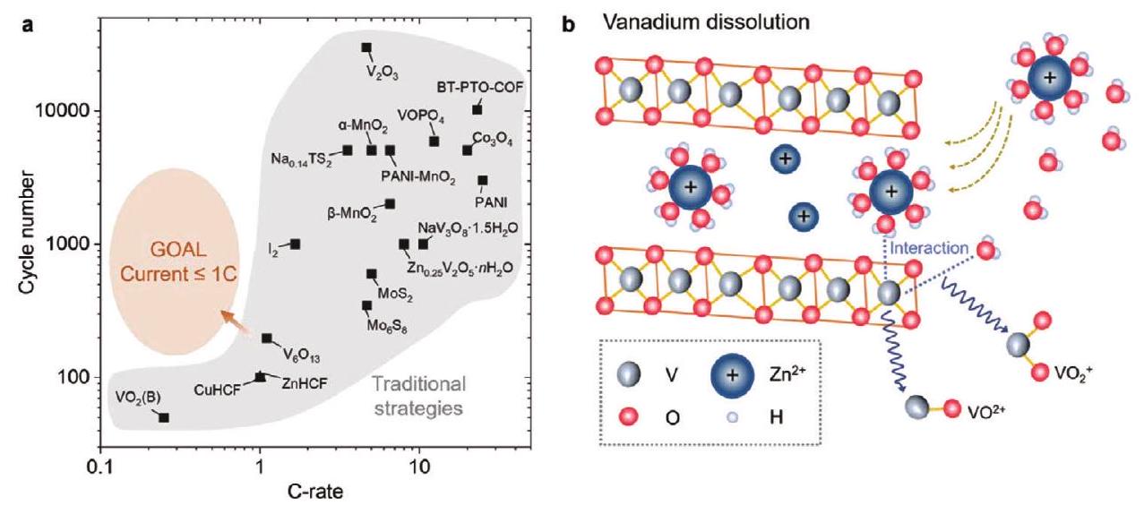
الشحن السريع. لديهم إمكانات كبيرة في استبدال بطاريات أيون الليثيوم (LIBs)، والرصاص الحمضي، وبطاريات النيكل-معدن الهجينة في الإلكترونيات القابلة للارتداء وتخزين الطاقة على نطاق واسع. في العقد الماضي، تم اقتراح استراتيجيات مختلفة في AZIBs لتحقيق كثافات الطاقة والقدرة التي تتجاوز بكثير تلك الخاصة بـ LIBs واستقرار دورة يبدو أنه أفضل عند التيارات العالية. تحت هذه الازدهار، يتم تجاهل أو التقليل من العديد من التحديات الكامنة وراء هذه الادعاءات بالأداء الكهربائي المتميز. إحدى القضايا الحرجة هي ضعف الاحتفاظ بالسعة عند كثافات تيار منخفضة (, كما هو موضح في الشكل 1a) لأن التيارات الصغيرة تزيد من ردود الفعل الجانبية، مثل الذوبان الحتمي للأقطاب الإيجابية (الشكل 1b، تم اختيار ذوبان أكاسيد الفاناديوم كمثال).
في الأبحاث السابقة، يمكن تخفيف ذوبان مواد الأقطاب الناجم عن بشكل فعال عن طريق تقليل النشاط، مثل الإلكتروليتات المائية في الملح والإلكتروليتات ذات الزحام الجزيئي. ومع ذلك، فإن هذه الاستراتيجيات تستهلك حتمًا المزايا الفريدة للإلكتروليتات المائية، مثل الموصلية الأيونية العالية، وعدم القابلية للاشتعال، والتكلفة المنخفضة، وعدم السمية. في
الشكل 1. تقييم حالي للكاثودات لـ AZIBs والمخطط لذوبان الأقطاب V. أ) تم تحليل بيانات الكاثود المنشورة من حيث معدل C وعدد الدورات. يتم توفير قيم معدل C إما في الأدبيات أو حسابها بناءً على أعلى سعة تفريغ تم الإبلاغ عنها ووزن المواد النشطة، على التوالي. تشمل المراجع المدرجة PANI-MnO2، تم تقديم أفضل أداء في هذا العمل أيضًا. ب) ذوبان كاثودات أكسيد الفاناديوم في AZIBs، و هي الأنواع المذابة عادة.
الإلكتروليتات المائية الشائعة حيث لا يتم تقليل نشاط الماء، من الصعب إزالة بسبب إنثالبي الترطيب العالي الخاص به (, كمقارنة، قيمة هي مما يبدو أنه يزيد من الاتصال وذوبان V الناتج. من ناحية أخرى، فإن عدم الاكتمال في إزالة يجلب التداخل المشترك لـ و (أو المائي). تم اعتبار هذا التداخل المشترك سابقًا عملية تثبت الشبكة.
على العكس من ذلك، وجدت محاكاة DFT لدينا أن المائي المتداخل يولد تجاويف كبيرة داخل تباعد الشبكة؛ في مثل هذه الظروف، يسرع التداخل المشترك الحر مع V المنسق جزئيًا من ذوبان V. وبالتالي، قدمنا مرحلة اصطناعية قابلة للاختراق من الزنك، كارهة للماء، وغير قابلة للاختراق من الفاناديوم على كاثودات أكسيد الفاناديوم. وفقًا لافتراضاتنا، يمكن أن تمنع هذه المرحلة الاصطناعية بشكل جذري تداخل، وتخفف بشكل كبير من ذوبان V من خلال ضبط توازن التفاعل المحلي. اتضح أن استراتيجيتنا فعالة جدًا لدرجة أن الخلية الكاملة تحقق واحدة من أفضل استقرارات الدورة تحت كثافات تيار منخفضة (
) حتى الآن (تقريبًا لا تتلاشى السعة بعد 200 دورة). بالنظر إلى الفهم الواضح لآلية تلاشي السعة وتصميم الهدف لهياكل الكاثود المركبة، توفر هذه العمل استراتيجية تصميم عالمية لبناء AZIBs عالية الاستقرار.
2. النتائج والمناقشةفي هذه الدراسة، التي تمتلك طبقات فردية ومزدوجة متناوبة تم اختيارها كمادة كاثود نموذجية، والتي يمكن اعتبارها مزيجًا من (طبقة واحدة) و هيكل (طبقتين)، تعرض الهياكل التمثيلية لكاثودات أكسيد الفاناديوم. تتكون مورفولوجيا المادة من شرائط نانوية مكدسة، كما هو موضح في صورة المجهر الإلكتروني الماسح (SEM) (الشكل S1a، المعلومات الداعمة). توفر هذه المورفولوجيا مساحة سطح نوعية أكبر و
مسار انتشار أيون أقصر من تلك الضخمة، مما يمكّن من تفاعل كامل ويساعد في فهمنا لعملية التفاعل. يؤكد نمط حيود الأشعة السينية (XRD) المعروض في الشكل S1b (المعلومات الداعمة) على نجاح تخليق مادة المرحلة النقية (JCPDS No. 19-1399). بالإضافة إلى ذلك، يكشف تحليلنا لقياس الطيف الكهروضوئي للأشعة السينية (XPS) لمنطقة V 2p (الشكل S1c، المعلومات الداعمة) عن حالات التكافؤ المختلطة لـ V. يؤكد طيف رامان المعروض في الشكل S2 (المعلومات الداعمة) هوية المادة كـ. بشكل جماعي، توفر هذه التوصيفات معلومات هيكلية أساسية للمادة التي تم تخليقها.
أجرينا سلسلة من المحاكاة حول التفاعل بين الحرة و تحت ظروف مختلفة لفهم سلوك ذوبان، الجدول S1، المعلومات الداعمة). يظهر الشكل 2a نقل شحنة معين بين الحرة وسطح الخارجي، مما يدل على التفاعل القوي بين السائل وذرة V غير المنسقة بسبب كسر الدورية. يؤدي هذا التفاعل إلى ظاهرة الذوبان لمواد في، كما اقترحت الأبحاث السابقة. بعد ذلك، فحصنا التفاعل بين الحرة و الشبكة المنسقة بالكامل. كما هو موضح في الشكل 2b، لم يكسر تفاعل بيئة التنسيق الكاملة لذرات V، مما يؤدي إلى تفاعل أضعف حتى من سطح الخارجي. ومع ذلك، فإن تشوهًا صغيرًا نسبيًا في شبكة قد لفت انتباهنا أن الهيكل الضخم لـ ليس مستقرًا كما كنا نعتقد. حتى مثل هذا الاضطراب الصغير يمكن أن يسبب تشوهًا في الهيكل، ناهيك عن المائي الذي يُلاحظ غالبًا في AZIBs (الشكل 2c). تزداد التشوهات الملحوظة كما توقعنا بينما تم ملاحظة نقل إلكترونات بالكاد، مما يشير إلى الربط الوثيق بين و في. يتماشى هذا الاكتشاف تمامًا مع إنثالبي الترطيب الكبير لـ (، الجدول S2، المعلومات الداعمة). وهذا بدوره يفسر لماذا يحدث تداخل المائي، حيث يصعب إزالة ترطيب.
تجريبيًا، يتبع تقدم الذوبان بشكل أساسي المعادلة التفاعلية أدناه، التي تصف التفاعل بين
c
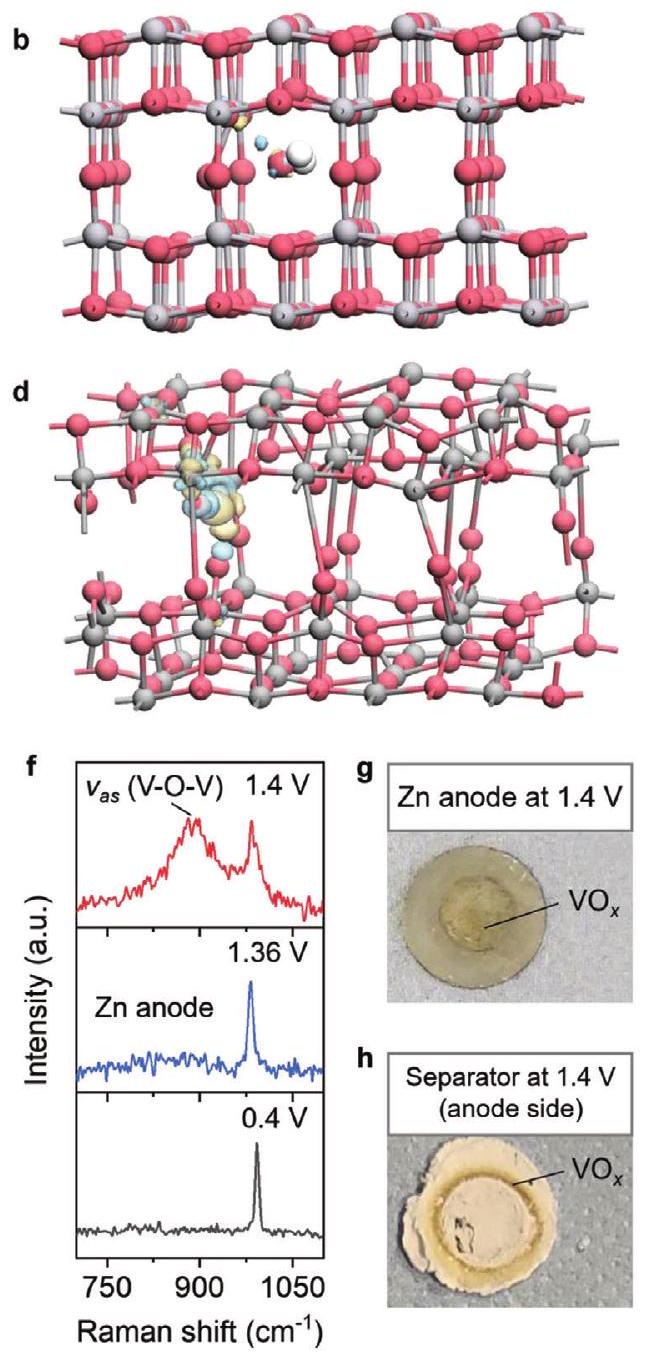
الشكل 2. التحقيقات النظرية والتجريبية لذوبان في. أ-د) مخططات فرق كثافة الشحنة من حسابات نظرية الكثافة الوظيفية (DFT) (تم تعيين قيمة العزل على 0.05، كرات رمادية وحمراء وبيضاء تمثل وH، على التوالي، والأسطح الصفراء والزرقاء تتوافق مع فقدان واكتساب الشحنة، على التوالي)، بما في ذلك بين الحرة وسطح الأصل المكشوف (011) من أ)، بين الحرة و الأصل الضخم ب)، بين من المائي المتداخل و )، وبين الحرة و بعد المائيالتداخل د). هـ) منحنى الشحن/التفريغ الجلفانيستاتيكي لـخلية بكثافة تيار قدرهاالجزء المضاف هو V- المعززمخطط بورباي، بينما يتم عرض المخطط بالكامل في الشكل S3، المعلومات الداعمة. تشير الخط الأحمر المنقط إلى pH 3.5، وهو ما يعادل pHالجهد عند هذا الرقم الهيدروجيني هو 1.36 فولت مقابلوينسب إلى حدود بين و طيف رامان لقطعة الزنك الأنودية في حالات الشحن/التفريغ المختلفة خلال الدورة الأولى.صور بصرية لأنود رقائق الزنك g) والفاصل الجانبي للأنود h) عند 1.4 فولت خلال عملية الشحن الأولى. (المنتج المثالي للشحن الكاثود) و تحت ظروف حمضية
بالإشارة إلىرسم بورباي (في الإطار في الشكل 2e)، لقد حددنا أن الانتقال منإلىيحدث فيلقد أظهرت تجاربنا أيضًا وجود هضبة شحن مطولة خلال عملية الشحن الأولى، مع نقطة التحول بالقرب من 1.36 فولت (الشكل 2e). يُعتقد أنالمادة الصلبة تذوب باستمرار خلال هذه العملية الشحن، مما يولدالمثير للاهتمام، المذابيهاجر إلى الأنود تحت تأثير المجال الكهربائي للشحن. وهذا مدعوم بالكشف عن- إشارة إلىإشارة على سطح أنود الزنك في نهاية الشحن (الشكل 2f)، بالإضافة إلى ملاحظة ترسب أصفر ترابي على أنود الزنك وعلى الفاصل من جهة الأنود (الشكل 2g، h). تشير قياسات طيف الامتياز الكهربائي (EIS) أيضًا إلى ظهور واجهة إضافية في نهاية الهضبة الطويلة للشحن، من المحتمل أن تت correspond إلى ترسب أنواع V المذابة والتوليد اللاحق لـطبقة الترسيب على سطح أنود الزنك (الشكل S4، المعلومات الداعمة).
ومع ذلك، فإن إدخاليؤدي إلى تشوه شبكي ملحوظ، مما يسمح بظهور العديد من الروابط المعلقة، مثل حالة المكشوفةالسطح في الشكل 2أ. لذلك، اعتبرنا التفاعل بين
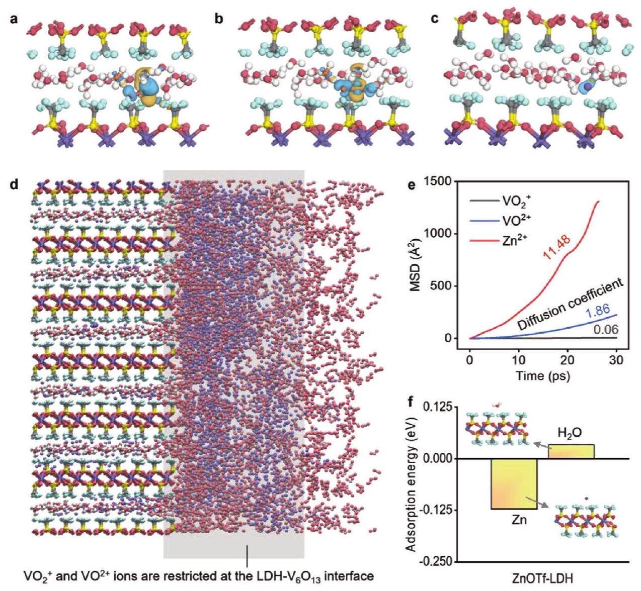
الشكل 3. الهيكل المحسن لـوالتفاعلات المقابلة لـ، و داخلها أو عبرها. أ-ج) فرق كثافة الشحنة عندما ) ، )، و نقل في ZnOTf -LDH بشكل فردي. تم تعيين قيمة العزل على 0.03. د) مخطط تأثير الاحتجاز لـ ZnOTf -LDH على و . هـ) متوسط الإزاحة التربيعية لأيونات مختلفة مع LDH. و) طاقة الامتزاز و في قناة ZnOTf-LDH.
مجانيفي الإلكتروليت المائي والشبكة عند الترطيب يتم إدخاله، كما هو موضح في الشكل 2d. كما هو متوقع، تم نقل درجة أكبر من الشحنة بين الشبكة المكسورة مع من ذلك على سطح الـ. من المتوقع أن تظهر هذه الحالة درجة أكبر من ذوبان الفاناديوم بسبب الأسطح غير المشبعة المعرضة بشكل مشابه لكل من الجزء العلوي والسفليالطبقات، التي تتماشى تمامًا مع التجارب. استنادًا إلى هذا الاكتشاف النظري، قمنا بتجميع الـخلية كاملة لمزيد من الدراسة. لمنع ذوبان V فيالكاثود، من الضروري تعديل التفاعل بينوالإلكترود. لمعالجة هذه المشكلة، قمنا بتطوير طبقة بين الكاثود والإلكتروليت (CEI) يمكن أن تدير هذه الحالة بفعالية. أفادت الدراسات السابقة بوجود CEI منالذي يمكن أن يتم توليده في الموقع علىالكاثود بسبب التداخل غير القابل للعكس لـ. من المثير للاهتمام أن جيل مثل ZnOTf-LDH لم يؤدي على الفور إلى تلاشي السعة. مستلهمين من هذه الظاهرة، قمنا بدراسة نفاذية الأنواع بعناية.
من خلال حسابات DFT وتحليل كثافة الشحنة التفاضلية، وجدنا أن و في القناة تتعرض لنقل شحنات شديد مع ZnOTf-LDH، بينمالا (الشكل 3أ-ج). وهذا يشير إلى أن أو يمكن محاصر في الـالشبكة في ZnOTf-LDH، بينمايمكن أن تمر عبر LDH بسهولة. لذلك، يمكن أن يقيد ZnOTfLDH و عند الواجهة بين و (الشكل 3د)، مما يمنع المزيد من ذوبان الفاناديوم. وقد تم التحقق من ذلك باستخدام الديناميات الجزيئية من أولى المبادئ (AIMD)، التي أظهرت قوةنفاذية ولكن نفاذية ضعيفة لـ و (الشكل 3e). بالإضافة إلى ذلك، تم إثبات أن ZnOTfLDH غير قابل للذوبان في الماء ولديه تقارب عالٍ للزنك (الشكل 3f). يمكن أن تؤدي هذه الخاصية إلى إزالة الماء.ومنع الثانويظاهرة التداخل الموجودة في الشكل 2d.
بالإضافة إلى ذلك، قمنا بدراسة سلوك التداخل لـومرطبفيمن خلال حسابات DFT (الشكل S5، المعلومات الداعمة). للـهناك قناتان للاختلاط (المسار 1 و 2) مع حواجز طاقة تبلغ 0.53 و 0.68 إلكترون فولت، بينما تكون مائيةلديه قناة انتشار واحدة فقط (المسار 1) مع حاجز طاقة أعلى يبلغ 1.54 إلكترون فولت بسبب تأثير الحجم. تشير النتيجة إلى أن إدخال ZnOTf-LDH قد يسهل الانتشار اللاحق لـفي المرحلة الكتلية بعد إزالة المذيب. تشير الأدبيات السابقة إلى أن ZnOTf-LDH يعاني من مشكلة تساقط بسببإزالة التداخل، التي تذوب ZnOTf-LDH عند الواجهة. لمعالجة هذه المشكلة، قمنا بتخليق ZnOTf-LDH كيميائيًا ولصقناه بـ
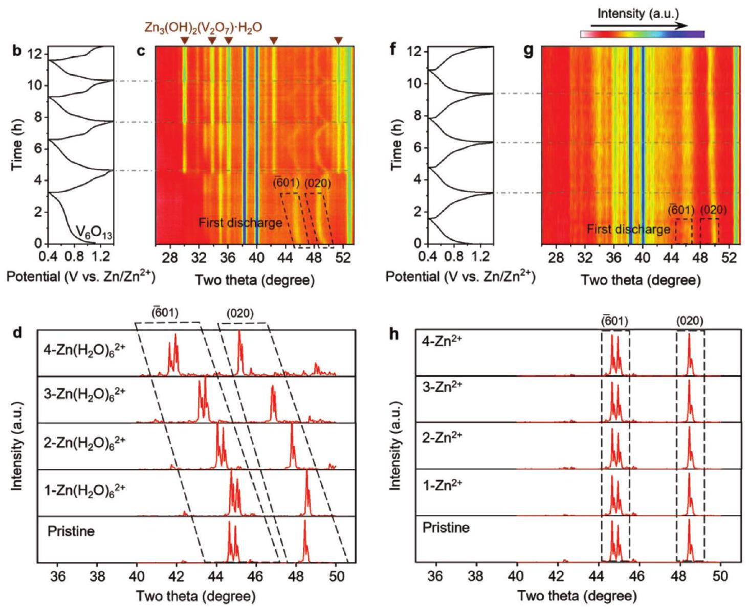
الشكل 4. سلوك التداخل داخل و @LDH. أ-د) القياسات الكهربائية الكيميائية والتوصيفات لـبما في ذلك منحنيات السعة مع معدل مسحأ) ، خصائص XRD في الموقع ومنحنيات الشحن/التفريغ المقابلة ب، ج) ، والتحولات المحاكاة لقمم الانكسار خلال التفريغ الأول د). رقم JCPDS لـالموضح في (ج) هو 01-087-0417. هـ-ي) القياسات الكهروكيميائية والتوصيفات لـ @LDH بما في ذلك منحنيات CV بمعدل مسح )، خصائص XRD في الموقع ومنحنيات الشحن/التفريغ المقابلة )، وتمت محاكاة تحولات قمم الانكسار خلال عملية التفريغ الأولى h). إن المستويات البلورية (601) و (020) من مُعَلَّمَة في (ج، د، ج، ح).
سطح الكاثود (المشار إليه بـتشير قياسات الفولتمترية الدورية (CV) (الشكل 4a,e) إلى أن المنحنيات لـ تكون منفصلة في الدورات القليلة الأولى بالقرب من 1.4 فولت، بينما تلك الخاصة بـ @LDH تتداخل، مما يشير إلى أن ذوبان الفاناديوم يتم تثبيته بعد إدخال ZnOTf-LDH CEI. من المثير للاهتمام، عند إمكانات التداخل حوليظهر فقط واحد قمم السيرة الذاتية الموسعة، بينمالديه قمتان منفصلتان في الجهد عند 0.503 و 0.656 فولت، تت correspond إلى إدخال الماء. و كما هو موضح في المحاكاة النظرية، على التوالي (الشكل S5، المعلومات الداعمة). علاوة على ذلك، قمنا بإجراء اختبارات EIS عند درجات حرارة متغيرة. طاقة تنشيط نقل الشحنة (يمكن تحديده من خلال رسم
الجدول 1. مقارنة الأداء.
عينات
احتفاظ السعة
كثافة التيار
إلكتروليت
المراجع.
89.9% بعد 50 دورة
[1غ]
95.8% بعد 50 دورة
[30]
نقص الأكسجين
96.7% بعد 50 دورة
[31]
97.5% بعد 50 دورة
[32]
PEDOT-
94.8% بعد 100 دورة
[33]
مُغَطَّى
90% بعد 100 دورة
[٣٤]
@C
92.1% بعد 150 دورة
[٣٥]
93% بعد 200 دورة
[36]
80% بعد 200 دورة
[14]
98.3% بعد 218 دورة
هذا العمل
و مقابل درجة الحرارة المعكوسة (الشكل S6، المعلومات الداعمة)، والتي تتبع معادلة أرهينيوس أين هو عامل التردد، هو طاقة التنشيط لنقل الشحنة على الواجهة، هو طاقة التنشيط لنقل الشحنات في الحالة الصلبة، هو ثابت الغاز، و هو درجة الحرارة المطلقة. الـ @LDH يظهر مستوى أعلى وأدنىمن، مما يشير إلى زيادة في المقاومة الواجهة بسبب إدخال طبقة التفاعل الكهربائية وانخفاض مقاومة الانتشار في الحالة الصلبة. يمكن أن يُعزى انخفاض الانتشار الأيوني في الحالة الصلبة إلى انتقال الأيونات المدخلة من الحالة المائيةإلىقمنا أيضًا بإجراء اختبارات XRD في الموقع على كلا العينتين. فيما يتعلق بـ (الشكل 4ب، ج)، قمم XRD التي تتوافق مع مستويي البلورة (601) (في البداية عند ) و (020) (في البداية عند ) يتم تحويلها إلى زوايا أقل أثناء التفريغ وإلى زوايا أعلى أثناء الشحن، مما يتوافق مع زيادة ثم انخفاض المسافة بين الطبقات، على التوالي، بينما كانت مواقع الذروة فيلا تظهر أي تحول كبير (الشكل 4f، g). وهذا يشير إلى (إزالة) إدخال الماء الكبير الحجم.فيبينمافي @LDH. في هذا الصدد، قمنا بإجراء محاكاة نحو XRD باستخدام حسابات DFT استنادًا إلى (إزالة) إدخال الماء المترطب. و في مرحلة الكتلة من، على التوالي (الشكل 4d، h)، ووجدنا أن إدخال الماء المترطبتسبب في زيادة كبيرة في المسافة بين الطبقات، بينمايؤدي إلى زيادة ضئيلة، وهو ما يتماشى مع نتائج XRD في الموقع. تشير هذه النتائج إلى أن ZnOTf-LDH يمكن أن يعمل كما هو موضح في الشكل 3.
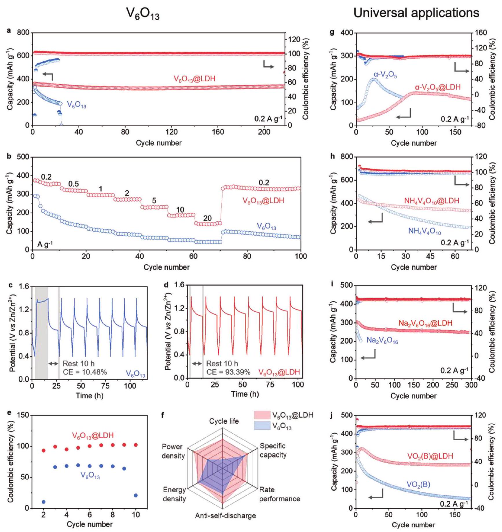
علاوة على ذلك، قمنا باختبار الأداء الكهروكيميائي للقطب السالب مع وبدون طلاء ZnOTf-LDH. عند كثافة تيار منخفضة مناحتفاظ السعة @ LDH قدمت بعد أكثر من 200 دورة (أي،كما هو موضح في الشكل 5أ)، وهو أفضل أداء للدراجات عند كثافات تيار منخفضة حتى الآن (الشكل 1أ والجدول 1). قيم الكفاءة الكولومبية لـخلال الدورات الأولية كانت أكثر من، مما يتوافق مع ذوبان الفاناديوم الشديد وتحريك أنواع الفاناديوم. إن تحسين أداء الدورة مرتبط ارتباطًا وثيقًا بالآلية المقترحة لدينا، والتي تستند إلى مبدأ لو شاتلييه، أي رفع المستوى المحلي التركيز والتقليل- ين التركيز من خلال وظيفة ، وبالتالي نقل توازن التفاعل في المعادلة (1) إلى اليسار ومنع المزيد من ذوبان V.بالإضافة إلى ذلك، أداء المعدل لـأعلى بكثير من ذلك لـ (الشكل 5ب)، بسبب التداخل في في السابق ومائيفي الأخير. كما هو موضح في الشكل 5c-e، فإن احتفاظ السعة بـ @LDH بعد الراحة يكون أعلى بشكل متسق من ، مما يشير إلى أن ZnOTf-LDH يثبط تبادل الأيونات التلقائي عند الواجهة وبالتالي الحصول على واجهة مستقرة. في النهاية، عمر الدورة، السعة النوعية، أداء المعدل، مقاومة التفريغ الذاتي، كثافة الطاقة، وكثافة القدرة لـكلها محسّنة بشكل أكبر من تلك الخاصة بـ (الشكل 5f). في النهاية، طبقنا هذا النهج ZnOTf-LDH على أمثلة أخرى نموذجيةمراحل، بما في ذلك، و (الشكل ). تظهر نتائجنا تحسنًا ملحوظًا في أداء الدراجات عند كثافة تيار عبر مختلفمواد الكاثود، مع تسليط الضوء على عمومية استراتيجيتنا.
3. الخاتمة
في الختام، حددت هذه الدراسة أن الماء المحتوي علىالتداخل يحفز تداخل الحر، مما يؤدي بشكل جوهري إلى ذوبان شديد لـ V فيالكاثودات. لمعالجة هذه المشكلة، قمنا بتصميم وتصنيع ZnOTf -LDH كطبقة عازلة اصطناعية علىسطح، يصدكتل، و ، ويسمح بنقل . هذا يقلل من المتفاعلويقتصر على الناتج و ، وبالتالي قمع ذوبان الفاناديوم بشكل فعال وفقًا لمبدأ لو شاتلييه. لذلك، حققنا أداءً مستقرًا في الدورات (أكثر من 200 دورة دون تدهور ملحوظ في السعة) عند كثافة تيار منخفضة ( ). تنفيذ توصيفات مفصلة، بما في ذلك تحليل حي XRD، وحسابات DFT، وتحليل كيميائي كهربائي، كما مكن CEI أيضًا من تحقيق مستوى أعلى ديناميكا الانتشار الناتجة عن الانتشار الصلب المعززبدلاً من ) وإزالة الترطيب من الماء المحتوي على . تم تطبيق هذه الاستراتيجية بشكل عالمي على، ، و الأنظمة، مما يحسن بشكل كبير من استقرارها في الدورة عند كثافات تيار منخفضة. تقدم نتائجنا رؤى جديدة حول مشكلة الذوبان للمواد القائمة على الفاناديوم وتوفر استراتيجية شاملة لتعزيز بطاريات AZIBs عالية السعة العملية.
الشكل 5. الأداء الشامل والتطبيقات العالمية للـ CEI الاصطناعي لـ ZnOTf-LDH. أ) أداء الدورة لـ و عند كثافة تيار. ب) تقييم أداء و @LDH عند كثافات تيار متغيرة. ج-هـ) أداء التفريغ الذاتي لـ و @LDH. الكثافة الحالية هي .هـ) هي إحصائيات ج) و د). و) مخطط راداري يقارن بين عمر الدورة، السعة النوعية، أداء المعدل، التفريغ الذاتي المضاد، كثافة الطاقة، وكثافة القدرة لـ و أداء ركوب الدراجات لـ و ) ، و و )، و و في.
4. القسم التجريبي
تركيبفي عملية التخليق النموذجية، 1.2 جرام من و 1.8 جرام من تمت إضافة 40 مل من الماء المقطر (DI). ثم تم تحريك المزيج الناتج مغناطيسيًا عندلمدة ساعة واحدة، مما أسفر عن محلول أزرق داكن. بعد ذلك، تم نقل هذا المحلول إلى وعاء أوتوكلاف مبطن بتفلون سعة 50 مل واحتفظ به فيلمدة 3 ساعات. بعد الانتهاء من التفاعل، تم السماح لجهاز الضغط بالبرودة إلى درجة حرارة الغرفة بشكل طبيعي. تم غسل المنتجات الناتجة بالإيثانول والماء المقطر، ثم تم تجفيفها عندبينما يتم جمعها في اليوم التالي.
تركيب : تخليق تم اقتباسه من ورقتين سابقتين.تم إضافة 1 مل من محلول 1 م من هيدروكسيد البوتاسيوم (KOH) بالتنقيط إلى 9 مل من محلول 3 م.المحلول. تم جمع الراسب الأبيض الناتج بعد الطرد المركزي بسرعة 4400 دورة في الدقيقة لمدة 10 دقائق. تم تصريف السائل العلوي، وتم غسل الراسب الأبيض الناتج بالماء وتجفيفه لـباستخدام جهاز التبخر الدوار المزود بحمام مائي يتم الاحتفاظ به عند.
تركيب عينات عالمية: الـتم استخدامه كما هو مشترا، بينما كانت طرق التخليق لـ، ، و تمت تكييفها مباشرة من الأدبيات السابقة.
توصيف المواد: تم إجراء قياسات حيّة للأشعة السينية باستخدام جهاز تحليل الأشعة السينية Bruker D8 Discover مع كاشف مساحي باستخداممصدر الأشعة السينية. تم إجراء تحليل XPS باستخدام جهاز VG Multilab 2000، بينما تم الحصول على طيف رامان باستخدام جهاز Horiba LabRAM HR Evolution مع ليزر تحفيز بطول موجي 532 نانومتر. تم الحصول على صور SEM ذات الانبعاث الميداني على جهاز JEOL-JSM-6700F بجهد 5 كيلو فولت وتيار انبعاث قدره.
القياسات الكهروكيميائية: الكاثود العامل لـتتكون من مواد نشطة ( )، مادة مضافة موصلة من أسود الأسيتيلين (20 وزن%)، وبولي فينيليدين فلوريد (PVDF) (10 وزن%). بالمقابل، الكاثود العامل لـ @LDH يحتوي على مواد نشطة ( ) ، ، مادة مضافة موصلة من أسود الأسيتيلين (20 وزن%)، وفلوريد البولي فينيليدين (PVDF) (10 وزن%). بعد الطحن لمدة 60 دقيقة، تم إضافة كمية مناسبة من NMP لتشكيل حبر متجانس، ثم تم صبه على ورق الكربون وتجفيفه فيبين عشية وضحاها. بعد ذلك، تم ثقب ورق الكربون إلى أوراق دائرية بقطر 16 مم لتكون كأقطاب سالبة. تم تجميع خلايا العملة 2032 مع القطب السالب، وورق فلتر الألياف الزجاجية كفاصل، ورقة معدنية من الزنك كقطب موجب. كانت الإلكتروليت المستخدمة هيمحلول مائي. تم إجراء اختبارات الشحن/التفريغ الجلفانية على نظام اختبار البطاريات Neware (شنتشن، الصين). بالإضافة إلى ذلك، تم إجراء قياسات الجهد المتناوب (CV) والتحليل الطيفي للإimpedance (EIS) استنادًا إلى خلايا Swagelok، باستخدام محطة العمل الكهروكيميائية Biologic VMP-3.
طرق ونماذج حسابية: تم إجراء جميع محاكاة DFT في العمل ضمن نموذج دوري بواسطة برنامج المحاكاة الأولية فيينا (VASP).تم استخدام تقريب التدرج العام (GGA) مع دالة التبادل والتفاعل بيردو-بورك-إرنزرهوف (PBE).طريقة الموجة المعززة بواسطة البروجيكتور (PAW)تم استخدامه لوصف تفاعلات الإلكترون-النواة، وكانت طاقة القطع لمجموعة الأساس الموجية المسطحة 450 إلكترون فولت. تم تعيين تكامل منطقة بريل علىمونكهورست-باك-شبكة نقطية للأنظمة ذات الأسطح. تم تحسين جميع هندسات الامتزاز باستخدام خوارزمية تدرج مترافق قائمة على القوة. طاقة الامتزاز ( ) تم تعريفه على أنه أين، و هي الطاقات الحرة للسطح، والمادة الممتصة في الطور الغازي، والمادة الممتصة على السطح، على التوالي. طريقة الصورة المتسلقة للنطاق المرن المدفوع (CINEB)تم تطبيقه للعثور على حالة الانتقال لحاجز الهجرة. علاوة على ذلك، تم تحديد معايير تقارب الطاقة والقوة إلى 1.0. لكل ذرة و لتحسين الهندسة، على التوالي. تم استخدام AIMD في هذا العمل باستخدام وحدة CASTEP، وكانت خطوة الزمن 0.5 فيمتوثانية لمدة 30 بيكوثانية للحصول على MSD (المسافة المربعة المتوسطة). كانت درجة حرارة محاكاة الديناميكا الجزيئية تتأرجح تحت السيطرة باستخدام خوارزمية منظمات الحرارة نوز-هوفر،وكانت درجة الحرارة المتوسطة محددة عند 300 كلفن.
المعلومات الداعمة
المعلومات الداعمة متاحة من مكتبة وايلي على الإنترنت أو من المؤلف.
شكر وتقدير
ساهم Y.D. و C.Z و J.L. و X.G. بالتساوي في هذا العمل. يود المؤلفون أن يشكروا مجلس أبحاث الهندسة والعلوم الفيزيائية (EPSRC، EP/V027433/3)، مركز EPSRC للتدريب على الدكتوراه في النمذجة الجزيئية وعلوم المواد (EP/L015862/1)، أبحاث المملكة المتحدة والابتكار (UKRI) بموجب تمويل الحكومة البريطانية هورايزون أوروبا (101077226؛ EP/Y008707/1)، المؤسسة المفتوحة لمختبر الدولة الرئيسي للمواد السيليكاتية للهندسة المعمارية (رقم SYSJJ2020-04) والتكنولوجيا المتقدمة لتخليق المواد ومعالجتها (جامعة ووهان للتكنولوجيا)، مشروع الابتكار العلمي والتكنولوجي في شنغهاي (22520710100) والجمعية الملكية (RGS/R1/211080؛ IEC/NSFC/201261) على دعم التمويل.
تعارض المصالح
يعلن المؤلفون عدم وجود أي تضارب في المصالح.
بيان توفر البيانات
البيانات التي تدعم نتائج هذه الدراسة متاحة من المؤلف المراسل عند الطلب المعقول.
الكلمات الرئيسية
ذوبان القطب، واجهة مفلورة، تصميم هيكلي، أكسيد الفاناديوم، بطاريات أيون الزنك
مختبر كريستوفر إنغولد قسم الكيمياء جامعة كوليدج لندن لندن WC1H 0AJ، المملكة المتحدة البريد الإلكتروني: g.he@ucl.ac.uk ي. داي، ب. هو، ج. زو، ل. ماي
المختبر الوطني الرئيسي للتكنولوجيا المتقدمة في تخليق المواد ومعالجتها جامعة ووهان للتكنولوجيا ووهان 430070، الصين البريد الإلكتروني: mlq518@whut.edu.cn
ي. داي، هـ. هي، د. ج. ل. بريت، ب. ر. شيرينغمختبر الابتكار الكهروكيميائيقسم الهندسة الكيميائيةجامعة كوليدج لندنلندن WC1E 7JE، المملكة المتحدةسي. زانغمدرسة العلوم الكيميائيةجامعة أوكلاندأوكلاند 1010، نيوزيلنداجي. ليالمختبر الرئيسي للاستخدام الشامل والفعال للغاية لموارد البحيرات المالحةالمختبر الرئيسي لموارد وكيمياء البحيرات المالحة في مقاطعة تشينغهايمعهد تشينغهاي للبحيرات المالحةالأكاديمية الصينية للعلومشيانغ، تشينغهاي 810008، الصينسي. ييقسم علوم المواد وعلم المعادنجامعة كامبريدجكامبريدج CB3 OFS، المملكة المتحدة
Inhibition of Vanadium Cathodes Dissolution in Aqueous Zn-Ion Batteries
Yuhang Dai, Chengyi Zhang, Jianwei Li, Xuan Gao, Ping Hu, Chumei Ye, Hongzhen He, Jiexin Zhu, Wei Zhang, Ruwei Chen, Wei Zong, Fei Guo, Ivan P. Parkin, Dan J. L. Brett, Paul R. Shearing, Liqiang Mai,* and Guanjie He**
Aqueous zinc-ion batteries (AZIBs) have experienced a rapid surge in popularity, as evident from the extensive research with over 30000 articles published in the past 5 years. Previous studies on AZIBs have showcased impressive long-cycle stability at high current densities, achieving thousands or tens of thousands of cycles. However, the practical stability of AZIBs at low current densities (<1C) is restricted to merely 50-100 cycles due to intensified cathode dissolution. This genuine limitation poses a considerable challenge to their transition from the laboratory to the industry. In this study, leveraging density functional theory (DFT) calculations, an artificial interphase that achieves both hydrophobicity and restriction of the outward penetration of dissolved vanadium cations, thereby shifting the reaction equilibrium and suppressing the vanadium dissolution following Le Chatelier’s principle, is described. The approach has resulted in one of the best cycling stabilities to date, with no noticeable capacity fading after more than 200 cycles ( ) at ( ). These findings represent a significant advance in the design of ultrastable cathodes for aqueous batteries and accelerate the industrialization of aqueous zinc-ion batteries.
1. Introduction
Aqueous Zn -ion batteries (AZIBs) promise inherent safety, environmental friendliness, high specific capacity, low cost, and
fast charging. They hold great potential in replacing lithium-ion batteries (LIBs), lead-acid, and nickel-metal hybrid batteries in wearable electronics and large-scale energy storage. In the past decade, various strategies have been proposed in AZIBs to achieve energy and power densities that far exceed those of LIBs and seemingly superior cycling stability at high currents. Under such prosperity, many challenges underlying these claims of outstanding electrochemical performances are overlooked or underestimated. One critical issue is the poor capacity retention at low current densities ( , as illustrated in Figure 1a) because small currents aggravate side reactions, such as the inevitable dissolution ofthe positive electrodes (Figure 1b, dissolution of vanadium oxides is selected as an example).
In previous research, the dissolution of electrode materials caused by can be effectively alleviated by reducing activity, such as water-in-salt and molecular crowding electrolytes. However, these strategies inevitably dissipate the unique advantages of aqueous electrolytes, such as high ionic conductivity, nonflammability, low cost, and nontoxicity. In
Figure 1. Current evaluation of cathodes for AZIBs and the schematic of V electrode dissolution. a) The published cathode data was analyzed in terms of C-rate and cycle number. C-rate values are either provided in the literature or calculated based on the highest reported discharge capacity and mass loading of active materials, respectively. The listed references include PANI-MnO2, The best performance in this work is also presented. b) Dissolution of vanadium oxide cathodes in AZIBs , the and are typically dissolved species.
common aqueous electrolytes where water activity is not attenuated, it is hard to desolvate due to its high hydration enthalpy ( , as a comparison, the value of is which seems to exacerbate the contact and derived V dissolution. On the other hand, the incomplete desolvation of brings the co-intercalation of and (or hydrated ). This co-intercalation was previously considered a process that stabilizes the lattice.
On the contrary, our DFT simulations found that the intercalated hydrated generates large cavities within the lattice spacing; under such circumstances, the co-intercalated free coordinates with the partially coordinated V accelerates the V dissolution. We thus introduced a zinc-permeable, hydrophobic, and vanadium-impermeable artificial interphase on the vanadium oxide cathodes. Under our hypotheses, such an artificial interphase could radically inhibit the intercalation of , and substantially mitigates V dissolution through adjusting local reaction equilibrium. Our strategy turns out to be so effective that the full cell achieves one of the best cycling stabilities under low current densities ( ) to date (almost no capacity fades after 200 cycles). Considering the clear understanding of the capacity fading mechanism and the target design of the composite cathode structures, this work provides a universal design strategy for the construction of highly stable AZIBs.
2. Results and Discussion
In this study, possessing alternating single and double layers was selected as a model cathode material, which can be considered as a mixed (single layer) and structure (double-layered), exhibiting the representative structures of vanadium oxide cathodes. The morphology of the material comprises stacked nanoribbons, as observed in the scanning electron microscope (SEM) image (Figure S1a, Supporting Information). This morphology provides a larger specific surface area and
shorter ion diffusion path than bulk ones, enabling a complete reaction and aiding our understanding of the reaction process. The powder X-ray diffraction (XRD) pattern shown in Figure S1b (Supporting Information) confirms the successful synthesis of pure phase material (JCPDS No. 19-1399). Additionally, our X-ray photoelectron spectroscopy (XPS) analysis of the V 2p region (Figure S1c, Supporting Information) reveals the mixed valence states of V. The Raman spectrum presented in Figure S2 (Supporting Information) further confirms the material’s identity as . Collectively, these characterizations provide basic structural information of the synthesized material.
We conducted a series of simulations about the interaction between free and under different circumstances to understand the dissolution behavior of , Table S1, Supporting Information). Figure 2a shows a certain charge transfer between the free and the outer surface, demonstrating the strong interaction between the fluent and the uncoordinated V atom due to the broken periodicity. Such interaction leads to the dissolution phenomenon of materials in , as suggested by previous research. Next, we examined the interaction between the free and the fully coordinated lattice. As shown in Figure 2b, the interaction of did not break the full coordination environment of V atoms, which results in an even weaker interaction than the external surface. However, a relatively small distortion of the lattice has caught our attention that the bulk structure of is not as stable as we thought. Even such a small perturbation can cause deformation of the structure, let alone the hydrated that is often observed in AZIBs (Figure 2c). Notable deformation surges as we expected while hardly transferred electrons were observed, indicating the tight binding between the and in . Such a finding is in full consistency with the large hydration enthalpy of ( , Table S2, Supporting Information). This in turn explains why the intercalation of hydrated occurs, since is difficult to dehydrate.
Experimentally, the dissolution progress basically follows the reaction equation below, which describes the reaction between
c
Figure 2. Theoretical and experimental investigations of the dissolution in . a-d) The charge density difference plots from density functional theory (DFT) calculations (the isovalue was set as 0.05 , gray, red, and white balls represent , and H atoms, respectively, and yellow and blue surfaces correspond to the loss and gain of charge, respectively), including between free and original surface exposing ( 011 ) plane of a), between free and original bulk b), between from the intercalated hydrated and ), and between free and after hydrated intercalation d). e) Galvanostatic charge/discharge curve of cell at a current density of . The inset is the amplified V- Pourbaix diagram, while the whole diagram is shown in Figure S3, Supporting Information. The red dotted line indicates a pH of 3.5, which is equivalent to the pH of . The voltage at this pH is 1.36 V versus and is attributed to a boundary between and . f) Raman spectrum of the Zn foil anode at different charge/discharge states during the first cycle. Optical images of the Zn foil anode g ) and the anode-side separator h) at 1.4 V during the first charge process. (the ideal charging product of cathode) and under acidic conditions
Referring to the Pourbaix diagram (inset in Figure 2e), we have determined that the transition from to occurs at . Our experiments have also shown a prolonged charging plateau during the first charging progress, with the turning point near 1.36 V (Figure 2e). It is speculated that the solid dissolves continuously during this charging process, generating . Intriguingly, the dissolved migrates to the anode under the charging electric field. This is supported by the detec-
tion of a signal on the Zn anode surface at the end of the charge (Figure 2f), as well as the observation of an earthy yellow precipitate on the Zn anode and on the anode-side separator (Figure 2g,h). Electrochemical impedance spectroscopy (EIS) measurements further indicate an additional interface emerges at the end of the long charging plateau, likely corresponding to the deposition of dissolved V species and the subsequent generation of a precipitation layer on the Zn anode surface (Figure S4, Supporting Information).
However, the intercalation of leads to a pronounced lattice distortion, allowing the appearance of many suspended bonds, like the state of the exposed surface in Figure 2a. Therefore, we considered the interaction between the
Figure 3. Optimized structure of and corresponding interactions of , and within it or across it. a-c) The charge density difference when ), ), and ) transfer in the ZnOTf -LDH individually. the Isovalue was set as 0.03 . d) Scheme of the confinement effect of ZnOTf -LDH on and . e) The mean square displacement of different ions with LDH. f) Adsorption energy of and in the channel of ZnOTf-LDH.
free in the aqueous electrolyte and the lattice when hydrated is intercalated, as shown in Figure 2d. As expected, an even greater degree of charge was transferred between the broken lattice with free than that on the surface of the . This state is anticipated to display a greater degree of V dissolution due to the similarly exposed unsaturated surfaces of both the upper and lower layers, which is fully consistent with the experiments. Based on this theoretical finding, we assembled the full cell for further study. To prevent V dissolution in the cathode, it is necessary to modify the interaction between and the electrode. To address this issue, we developed a cathode-electrolyte interlayer (CEI) that could effectively manage this situation. Previous studies reported a CEI of that could be generated in situ on the cathode due to the irreversible intercalation of . Interestingly, the generation of such ZnOTf-LDH did not immediately result in the capacity fading. Inspired by this phenomenon, we carefully investigated its species permeability.
Through DFT calculations and differential charge density analysis, we found that and in the channel undergo severe charge transfer with ZnOTf-LDH, while does not (Figure 3a-c). This indicates that or can
be trapped in the network in the ZnOTf-LDH, while could pass through the LDH easily. Therefore, ZnOTfLDH could confine and at the interface between and (Figure 3d), preventing further V dissolution. This was verified using ab initio molecular dynamics (AIMD), which showed strong permeability but weak permeability of and (Figure 3e). Additionally, ZnOTfLDH was proved to be hydrophobic and highly Zn affinitive (Figure 3f). Such quality could desolvate and prevent the secondary intercalation phenomenon found in Figure 2d.
In addition, we examined the intercalation behavior of and hydrated in through DFT calculations (Figure S5, Supporting Information). For , there are two diffusion channels (paths 1 and 2 ) with corresponding energy barriers of 0.53 and 0.68 eV , while hydrated has only one diffusion channel (path 1) with a higher energy barrier of 1.54 eV due to the size effect. The result indicates that the introduction of ZnOTf-LDH may facilitate subsequent diffusion of in the bulk phase after its desolvation. Previous literature reports that ZnOTf-LDH has a shedding problem due to deintercalation, which dissolves the ZnOTf-LDH at the interface. To address this issue, we chemically synthesized ZnOTf-LDH and stuck it to the
Figure 4. Intercalation behavior within and @LDH. a-d) Electrochemical measurements and characterizations of including CV curves with a scan rate of a), in situ XRD characterizations and corresponding charge/discharge curves b,c), and simulated shifts of the diffraction peaks during the 1st discharging d). The JCPDS No. of the shown in (c) is 01-087-0417. e-h) Electrochemical measurements and characterizations of @LDH including CV curves with a scan rate of ), in situ XRD characterizations and corresponding charge/discharge curves ), and simulated shifts of the diffraction peaks during the 1st discharging h). The (601) and (020) crystal planes of are labeled in (c,d,g,h).
cathode surface (noted as . The cyclic voltammetry (CV) measurements (Figure 4a,e) indicate that the curves of are discrete in the first few cycles near 1.4 V , while those of @LDH are overlapping, indicating V dissolution is suppressed after introducing the ZnOTf-LDH CEI. Interestingly, at the intercalation potential around shows only
one broadened CV peak, while has two separated CV peaks at 0.503 and 0.656 V , corresponding to the intercalation of hydrated and as shown in the theoretical simulation, respectively (Figure S5, Supporting Information). Moreover, we carried out variable temperature EIS tests. The charge transfer activation energy ( ) can be determined through plotting the
Table 1. Performance comparison.
Samples
Capacity retention
Current density
Electrolyte
Refs.
89.9% after 50 cycles
[1g]
95.8% after 50 cycles
[30]
Oxygen-deficient
96.7% after 50 cycles
[31]
97.5% after 50 cycles
[32]
PEDOT-
94.8% after 100 cycles
[33]
-coated
90% after 100 cycles
[34]
@C
92.1% after 150 cycles
[35]
93% after 200 cycles
[36]
80% after 200 cycles
[14]
98.3% after 218 cycles
This work
and versus reciprocal temperature (Figure S6, Supporting Information), which obey the Arrhenius equation
where is the frequency factor, is the activation energy for interfacial charge transfer, is the activation energy for solid-state charge transfer, is the gas constant, and is absolute temperature. The @LDH exhibits a higher and lower than , indicating an increased interfacial resistance due to the introduction of a CEI and a decreased solid-state diffusion resistance. The decreased solid-state ionic diffusion can be attributed to the intercalated ions transitioning from hydrated to . We further performed in situ XRD tests on both samples. Regarding the (Figure 4b,c), the XRD peaks corresponding to the two crystal planes (601) (initially at ) and (020) (initially at ) are shifted to lower angles during discharging and to higher angles during charging, corresponding to the increase and then decrease of the interlayer spacing, respectively, while the peak positions in exhibit no significant shift (Figure 4f,g). This suggests (de)intercalation of the large-size hydrated in , while in @LDH. In this regard, we performed simulations toward XRD using DFT calculations based on the (de)intercalated hydrated and in the bulk phase of , respectively (Figure 4d,h), and found that the intercalation of hydrated did cause a significant increase in the interlayer spacing, while induces negligible increase, which is consistent with the in situ XRD results. These results suggest that ZnOTf-LDH can function as described in Figure 3.
Furthermore, we tested the electrochemical performance of the cathodes with and without ZnOTf-LDH coatings. At a low current density of , the capacity retention of @ LDH presented after over 200 cycles (i.e., , as seen in Figure 5a), which is the best cycling performance at low current densities so far (Figure 1a and Table 1). The Coulombic efficiency values of during initial cycles were over , corresponding to the severe V dissolution and shuttling of V species. The improved cycling performance is inextricably linked to our proposed mechanism, which is based on Le Chatelier’s principle, i.e., elevating local concentration and decreas-
ing concentration through the function of , thus shifting the reaction equilibrium in Equation (1) to the left and inhibiting further V dissolution. In addition, the rate performance of is also much higher than that of (Figure 5b), due to the intercalation of in the former and hydrated in the latter. As seen in Figure 5c-e, the capacity retention of @LDH after resting is consistently much higher than that of , indicating that the ZnOTf-LDH suppresses the spontaneous ion exchange at the interface and thus obtaining a stable interface. Ultimately, the cycle life, specific capacity, rate performance, antiself-discharge, energy density, and power density of are all much more improved than those of (Figure 5f). In the end, we applied this ZnOTf-LDH approach to other typical phases, including , and (Figure ). Our results demonstrate a significant improvement in cycling performance at a current density of across various cathode materials, highlighting the generalizability of our strategy.
3. Conclusion
In conclusion, this study has identified that hydrated intercalation triggers intercalation of free , which intrinsically leads to severe V dissolution in cathodes. To address this issue, we designed and synthesized ZnOTf -LDH as an artificial CEI on the surface, which repels , blocks , and , and allows the transport of . This reduces the reactant and confines the generated and , thus effectively suppressing the V dissolution following Le Chatelier principle. Therefore, we achieved stable cycling performance (over 200 cycles without remarkable capacity fading) at a low current density ( ). Implementing detailed characterizations, including in situ XRD, DFT calculations, and electrochemical analysis, the CEI also enabled a higher diffusion kinetics originating from facilitated solid-state diffusion ( rather than ) and desolvation of hydrated . This strategy was universally applied to , , and systems, significantly improving their cycling stability at low current densities. Our findings offer new insights into the dissolution problem of V-based materials and provide a pervasive strategy to promote practical high-capacity AZIBs.
Figure 5. Comprehensive performance and universal applications of the artificial CEI of ZnOTf-LDH. a) Cycling performance of and at a current density of . b) Rate performance of and @LDH at varying current densities. c-e) Self-discharge performances of and @LDH. The current density is .e) is the statistics of c) and d). f) Radar chart comparing cycle life, specific capacity, rate performance, antiself-discharge, energy density, and power density of and @LDH. g-j) Cycling performance of and ), and and ), and and at .
4. Experimental Section
Synthesis of : In the typical synthesis process, 1.2 g of and 1.8 g of were added to 40 mL of deionized (DI) water. The resulting mixture was then magnetically stirred at for 1 h , yielding a dark blue solution. Subsequently, this solution was transferred into a 50 mL Teflon-lined autoclave and kept at for 3 h . After the completion of the reaction, the autoclave was allowed to cool down to room temperature naturally. The resulting products were washed with ethanol and DI water, then dried at overnight before being collected.
Synthesis of : The synthesis of was adapted from two previous papers. Specifically, 1 mL of 1 m KOH was added dropwise into 9 mL of 3 m solution. The resulting white precipitate was then collected after centrifugation at 4400 rpm for 10 min . The supernatant liquid was decanted, and the resulting white precipitate was washed with water and dried for using a rotary evaporator equipped with a water bath held at .
Synthesis of Universal Samples: The was used as purchased, while the synthesis methods for , , and were directly adapted from previous literature.
Materials Characterizations: XRD and in situ XRD measurements were conducted using a Bruker D8 Discover X-ray diffractometer with an area detector using X-ray source. XPS analysis was performed with a VG Multilab 2000 instrument, while the Raman spectra were acquired using a Horiba LabRAM HR Evolution with an excitation laser of 532 nm . Fieldemission SEM images were obtained on a JEOL-JSM-6700F with a voltage of 5 kV and an emission current of .
Electrochemical Measurements: The working cathode of comprised active materials ( ), acetylene black conductive additive (20 wt%), and polyvinylidene fluoride (PVDF) (10 wt%). In contrast, the working cathode of @LDH contained active materials ( ), , acetylene black conductive additive (20 wt%), and polyvinylidene fluoride (PVDF) (10 wt%). After grinding for 60 min , an appropriate amount of NMP was added to form a homogenous ink, and then it was cast onto carbon paper and dried at overnight. Subsequently, the carbon paper was punched into circular sheets with a diameter of 16 mm to serve as cathodes. 2032 coin cells were assembled with the cathode, glass fiber filter paper as a separator, zinc metal foil as an anode. The electrolyte used was aqueous solution. Galvanostatic charge/discharge tests were undertaken on a Neware battery test system (Shenzhen, China). Additionally, CV and EIS were performed based on Swagelok cells, using a Biologic VMP-3 electrochemical workstation.
Computational Methods and Models: All the DFT simulations in the work were performed within a periodic model by the Vienna ab initio simulation program (VASP). The generalized gradient approximation (GGA) was used with the Perdew-Burke-Ernzerhof (PBE) exchange-correlation functional. The projector-augmented wave (PAW) method was utilized to describe the interactions of the electron-nucleus, and the cut-off energy for the plane-wave basis set was 450 eV . Brillouin zone integration was set as Monkhorst-Pack -point mesh for systems with surfaces. All the adsorption geometries were optimized using a force-based conjugate gradient algorithm. The adsorption energy ( ) was defined as
where , and are the free energies of the surface, adsorbate in the gas phase, and adsorbate adsorbed on the surface, respectively. The climbing image nudged elastic band (CINEB) method was applied to find the transition state for the migration barrier. Moreover, the criteria of energy and force convergence were set to 1.0 per atom and for geometry optimization, respectively. AIMD was used in this work using the CASTEP module, and the time step was 0.5 fs for 30 ps to obtain the MSD (mean square distance). The temperature of the MD simulation was oscillating controlled using the
algorithm of Nose-Hoover thermostats, and the average temperature was set to 300 K .
Supporting Information
Supporting Information is available from the Wiley Online Library or from the author.
Acknowledgements
Y.D., C.Z, J.L., and X.G. contributed equally to this work. The authors would like to thank the Engineering and Physical Sciences Research Council (EPSRC, EP/V027433/3), EPSRC Centre for Doctoral Training in Molecular Modelling and Materials Science (EP/L015862/1), UK Research and Innovation (UKRI) under the UK government’s Horizon Europe funding (101077226; EP/Y008707/1), Open Foundation of the State Key Laboratory of Silicate Materials for Architectures (No. SYSJJ2020-04) and Advanced Technology for Materials Synthesis and Processing (Wuhan University of Technology), Shanghai Scientific and Technological Innovation Project (22520710100) and the Royal Society (RGS/R1/211080; IEC/NSFC/201261) for funding support.
Conflict of Interest
The authors declare no conflict of interest.
Data Availability Statement
The data that support the findings of this study are available from the corresponding author upon reasonable request.
Received: October 12, 2023
Revised: December 31, 2023 Published online:
[1] a) Y. Yuan, R. Sharpe, K. He, C. Li, M. T. Saray, T. Liu, W. Yao, M. Cheng, H. Jin, S. Wang, K. Amine, R. Shahbazian-Yassar, M. S. Islam, J. Lu, Nat. Sustainability 2022, 5, 890; b) C. Zhong, B. Liu, J. Ding, X. Liu, Y. Zhong, Y. Li, C. Sun, X. Han, Y. Deng, N. Zhao, W. Hu, Nat. Energy 2020, 5, 440; c) X. Jia, C. Liu, Z. G. Neale, J. Yang, G. Cao, Chem. Rev. 2020, 120, 7795; d) L. Ma, M. A. Schroeder, O. Borodin, T. P. Pollard, M. S. Ding, C. Wang, K. Xu, Nat. Energy 2020, 5, 743; e) E. Hu, X. Yang, Nat. Mater. 2018, 17, 480; f) H. Pan, Y. Shao, P. Yan, Y. Cheng, K. S. Han, Z. Nie, C. Wang, J. Yang, X. Li, P. Bhattacharya, K. T. Mueller, J. Liu, Nat. Energy 2016, 1, 16039; g) D. Kundu, B. D. Adams, V. Duffort, S. H. Vajargah, L. F. Nazar, Nat. Energy 2016, 1, 16119; h) Y. Dai, C. Zhang, W. Zhang, L. Cui, C. Ye, X. Hong, J. Li, R. Chen, W. Zong, X. Gao, J. Zhu, P. Jiang, Q. An, D. J. L. Brett, I. P. Parkin, G. He, L. Mai, Angew. Chem., Int. Ed. 2023, 62, 202301192.
[2] a) R. F. Service, Science 2021, 372, 890; b) F. Wang, O. Borodin, T. Gao, X. Fan, W. Sun, F. Han, A. Faraone, J. A. Dura, K. Xu, C. Wang, Nat. Mater. 2018, 17, 543; c) B. Qiu, K. Liang, W. Huang, G. Zhang, C. He, P. Zhang, H. Mi, Adv. Energy Mater. 2023, 13, 2301193; d) Z. Zhu, Z. Lin, Z. Sun, P. Zhang, C. Li, R. Dong, H. Mi, Rare Mater. 2022, 41, 3729.
[3] a) Z. Wang, Y. Song, J. Wang, Y. Lin, J. Meng, W. Cui, X. X. Liu, Angew. Chem., Int. Ed. 2023, 62, 202216290; b) W. Wang, C. Yang, X. Chi, J. Liu, B. Wen, Y. Liu, Energy Storage Mater. 2022, 53, 774.
[4] a) L. E. Blanc, D. Kundu, L. F. Nazar, Joule 2020, 4, 771; b) C. Li, S. Jin, L. A. Archer, L. F. Nazar, Joule 2022, 6, 1733; c) B. Qiu, L. Xie, G. Zhang, K. Cheng, Z. Lin, W. Liu, C. He, P. Zhang, H. Mi, Chem. Eng. J. 2022, 449, 137843.
[5] a) W. Yang, Y. Yang, H. Yang, H. Zhou, ACS Energy Lett. 2022, 7, 2515 ; b) Y. Kim, Y. Park, M. Kim, J. Lee, K. J. Kim, J. W. Choi, Nat. Commun. 2022, 13, 2371.
[6] X. Wu, Y. Xu, C. Zhang, D. P. Leonard, A. Markir, J. Lu, X. Ji, J. Am. Chem. Soc. 2019, 141, 6338.
[7] a) J. Xie, Z. Liang, Y. C. Lu, Nat. Mater. 2020, 19, 1006; b) H. Ren, S. Li, B. Wang, Y. Zhang, T. Wang, Q. Lv, X. Zhang, L. Wang, X. Han, F. Jin, C. Bao, P. Yan, N. Zhang, D. Wang, T. Cheng, H. Liu, S. Dou, Adv. Mater. 2023, 35, 2208237.
[8] D. W. Smith, J. Chem. Educ. 1977, 54, 540.
[9] a) W. Sun, F. Wang, S. Hou, C. Yang, X. Fan, Z. Ma, T. Gao, F. Han, R. Hu, M. Zhu, C. Wang, J. Am. Chem. Soc. 2017, 139, 9775; b) M. J. Park, H. Yaghoobnejad Asl, A. Manthiram, ACS Energy Lett. 2020, 5, 2367; c) S. Li, C. Huang, L. Gao, Q. Shen, P. Li, X. Qu, L. Jiao, Y. Liu, Angew. Chem., Int. Ed. 2022, 61, 202211478.
[10] L. Wang, K. W. Huang, J. Chen, J. Zheng, Sci. Adv. 2019, 5, eaax4279.
[11] J. Ding, Z. Du, L. Gu, B. Li, L. Wang, S. Wang, Y. Gong, S. Yang, Adv. Mater. 2018, 30, 1800762.
[12] R. Trocoli, F. L. Mantia, ChemSusChem 2015, 8, 481.
[13] L. Zhang, L. Chen, X. Zhou, Z. Liu, Adv. Energy Mater. 2015, 5, 1400930.
[14] J. Shin, D. S. Choi, H. J. Lee, Y. Jung, J. W. Choi, Adv. Energy Mater. 2019, 9, 1900083.
[15] Y. Cheng, L. Luo, L. Zhong, J. Chen, B. Li, W. Wang, S. X. Mao, C. Wang, V. L. Sprenkle, G. Li, J. Liu, ACS Appl. Mater. Interfaces 2016, 8, 13673.
[16] H. Li, Q. Yang, F. Mo, G. Liang, Z. Liu, Z. Tang, L. Ma, J. Liu, Z. Shi, C. Zhi, Energy Storage Mater. 2019, 19, 94.
[17] G. Liang, J. Zhu, B. Yan, Q. Li, A. Chen, Z. Chen, X. Wang, B. Xiong, J. Fan, J. Xu, C. Zhi, Energy Environ. Sci. 2022, 15, 1086.
[18] F. Wan, L. Zhang, X. Dai, X. Wang, Z. Niu, J. Chen, Nat. Commun. 2018, 9, 1656.
[19] N. Zhang, F. Cheng, J. Liu, L. Wang, X. Long, X. Liu, F. Li, J. Chen, Nat. Commun. 2017, 8, 405.
[20] F. Wan, L. Zhang, X. Wang, S. Bi, Z. Niu, J. Chen, Adv. Funct. Mater. 2018, 28, 1804975.
[21] W. Li, K. Wang, S. Cheng, K. Jiang, Adv. Energy Mater. 2019, 9, 1900993.
[22] J. Huang, Z. Wang, M. Hou, X. Dong, Y. Liu, Y. Wang, Y. Xia, Nat. Commun. 2018, 9, 2906.
[23] L. Cao, D. Li, T. Pollard, T. Deng, B. Zhang, C. Yang, L. Chen, J. Vatamanu, E. Hu, M. J. Hourwitz, L. Ma, M. Ding, Q. Li, S. Hou, K.
Gaskell, J. T. Fourkas, X. Q. Yang, K. Xu, O. Borodin, C. Wang, Nat. Nanotechnol. 2021, 16, 902.
[24] L. Ma, S. Chen, H. Li, Z. Ruan, Z. Tang, Z. Liu, Z. Wang, Y. Huang, Z. Pei, J. A. Zapien, C. Zhi, Energy Environ. Sci. 2018, 11, 2521.
[25] S. Zheng, D. Shi, D. Yan, Q. Wang, T. Sun, T. Ma, L. Li, D. He, Z. Tao, J. Chen, Angew. Chem., Int. Ed. 2022, 61, 202117511.
[26] K. Zhu, S. Wei, H. Shou, F. Shen, S. Chen, P. Zhang, C. Wang, Y. Cao, X. Guo, M. Luo, H. Zhang, B. Ye, X. Wu, L. He, L. Song, Nat. Commun. 2021, 12, 6878.
[27] X. Wang, B. Xi, X. Ma, Z. Feng, Y. Jia, J. Feng, Y. Qian, S. Xiong, Nano Lett. 2020, 20, 2899.
[28] N. Zhang, X. Chen, M. Yu, Z. Niu, F. Cheng, J. Chen, Chem. Soc. Rev. 2020, 49, 4203.
[29] H. Wang, L. Wang, D. Lin, X. Feng, Y. Niu, B. Zhang, F.-S. Xiao, Nat. Catal. 2021, 4, 418.
[30] Y. Dai, X. Liao, R. Yu, J. Li, J. Li, S. Tan, P. He, Q. An, Q. Wei, L. Chen, X. Hong, K. Zhao, Y. Ren, J. Wu, Y. Zhao, L. Mai, Adv. Mater. 2021, 33, 2100359.
[31] M. Liao, J. Wang, L. Ye, H. Sun, Y. Wen, C. Wang, X. Sun, B. Wang, H. Peng, Angew. Chem., Int. Ed. 2020, 59, 2273.
[32] W. Liang, D. Rao, T. Chen, R. Tang, J. Li, H. Jin, Angew. Chem., Int. Ed. 2022, 61, 202207779.
[33] D. Bin, W. Huo, Y. Yuan, J. Huang, Y. Liu, Y. Zhang, F. Dong, Y. Wang, Y. Xia, Chem 2020, 6, 968.
[34] J. Guo, J. Ming, Y. Lei, W. Zhang, C. Xia, Y. Cui, H. N. Alshareef, ACS Energy Lett. 2019, 4, 2776.
[35] X. Wang, Z. Zhang, M. Huang, J. Feng, S. Xiong, B. Xi, Nano Lett. 2022, 22, 119.
[36] K. Zhu, T. Wu, W. van den Bergh, M. Stefik, K. Huang, ACS Nano 2021, 15, 10678.
[37] a) Q. Li, Y. Liu, K. Ma, G. Yang, C. Wang, Small Methods 2019, 3, 1900637; b) A. Moezzi, M. B. Cortie, A. M. McDonagh, Dalton Trans. 2013, 42, 14432.
[38] J. Li, N. Luo, F. Wan, S. Zhao, Z. Li, W. Li, J. Guo, P. R. Shearing, D. J. L. Brett, C. J. Carmalt, G. Chai, G. He, I. P. Parkin, Nanoscale 2020, 12, 20638.
[39] P. Hu, T. Zhu, X. Wang, X. Wei, M. Yan, J. Li, W. Luo, W. Yang, W. Zhang, L. Zhou, Z. Zhou, L. Mai, Nano Lett. 2018, 18, 1758.
[40] a) G. Kresse, J. Furthmüller, Comput. Mater. Sci. 1996, 6, 15; b) G. Kresse, J. Hafner, Phys. Rev. B 1994, 49, 14251.
[41] J. P. Perdew, K. Burke, M. Ernzerhof, Phys. Rev. Lett. 1996, 77, 3865. a) P. E. Blöchl, O. Jepsen, O. K. Andersen, Phys. Rev. B 1994, 49, 16223; b) G. Kresse, D. Joubert, Phys. Rev. B 1999, 59, 1758.
[43] G. Henkelman, B. P. Uberuaga, H. Jónsson, J. Chem. Phys. 2000, 113, 9901.
[44] a) W. G. Hoover, Phys. Rev. A 1985, 31, 1695; b) S. Nosé, J. Chem. Phys. 1984, 81, 511.
Y. Dai, J. Li, X. Gao, H. He, J. Zhu, W. Zhang, R. Chen, W. Zong, F. Guo, I. P. Parkin, G. He
Christopher Ingold Laboratory
Department of Chemistry
University College London
London WC1H 0AJ, UK
E-mail: g.he@ucl.ac.uk
Y. Dai, P. Hu, J. Zhu, L. Mai
State Key Laboratory of Advanced Technology for Materials Synthesis and Processing
Wuhan University of Technology
Wuhan 430070, China
E-mail: mlq518@whut.edu.cn
Y. Dai, H. He, D. J. L. Brett, P. R. ShearingElectrochemical Innovation LabDepartment of Chemical EngineeringUniversity College LondonLondon WC1E 7JE, UKC. ZhangSchool of Chemical SciencesThe University of AucklandAuckland 1010, New ZealandJ. LiKey Laboratory of Comprehensive and Highly Efficient Utilization of Salt Lake ResourcesQinghai Province Key Laboratory of Resources and Chemistry of Salt LakesQinghai Institute of Salt LakesChinese Academy of SciencesXining, Qinghai 810008, ChinaC. YeDepartment of Materials Science and MetallurgyUniversity of CambridgeCambridge CB3 OFS, UK
 يمكن العثور على رقم التعريف ORCID للمؤلفين في هذه المقالة تحتhttps://doi.org/10.1002/adma. 202310645