تحفيز التباين الهيكلي بين المواقع لكتاليسرات الحديد أحادية الذرة من أجل تقليل الأكسجين بشكل قوي Inter-site structural heterogeneity induction of single atom Fe catalysts for robust oxygen reduction
تعتبر المحفزات المعدنية-النيتروجين-الكربون ذات المسامية الموزعة بشكل هرمي هندسة فعالة لتفاعل اختزال الأكسجين (ORR). ومع ذلك، فإن الأداء التحفيزي الذي تحدده المواقع الفردية والتفاعلية الناتجة عن التباين الهيكلي يعد غامضًا بشكل خاص ولا يزال بحاجة إلى الفهم. هنا، تم تحضير محفز ذرة الحديد المفرد ذو المسامية الهرمية (Fe SAs-HP) مع وجود كثيف لذرات الحديد في المسام الدقيقة والمسامات المتوسطة. يظهر Fe SAs-HP أداءً قويًا في تفاعل اختزال الأكسجين مع جهد نصف الموجة يبلغ 0.94 فولت وتردد دوران لـعند 0.80 فولت. تكشف المحاكاة النظرية عن تحسين ناتج عن تباين هيكلي، حيث المسام الميكرونيةتعمل كمراكز نشطة حقيقية نتيجة لتنظيم الإلكترونات على المدى الطويل بواسطة المواقع المجهرية المجاورة، مما يسهلتنشيط وإزالة المفتاح الوسيط *OH. تحدد نتائج التوصيف متعدد المستويات في الظروف التشغيلية مواقع الحديد النشطة التي تخضع لتطور ديناميكي من الأساسإلى نشطتحت ظروف العمل. تكشف نتائجنا عن الأصل الهيكلي للنشاط الداخلي المعزز للمواد المسامية الهرمية.المواقع.
تتطلب المخاوف المتزايدة بشأن قضايا الطاقة والبيئة طاقة نظيفة. تمثل خلايا الوقود وبطاريات المعدن-الهواء مرشحين واعدين للجيل القادم من أنظمة تحويل وتخزين الطاقة بسبب كثافتها العالية من الطاقة، وتكلفتها المنخفضة، وصديقها للبيئة، وغيرها.ومع ذلك، فإن تطوير مثل هذه التكوينات المتقدمة لتحويل الطاقة يعوقه بطء حركيات تفاعل اختزال الأكسجين (ORR) والتكلفة العالية لمحفزات المعادن الثمينة في الكاثودات الهوائية. لقد أعادت ظهور المحفزات ذات الذرة الواحدة (SACs) ذات الاستخدام العالي للذرات والمواقع النشطة القابلة للتعديل إحياء اهتمام كبير لمعالجة النشاط والمتانة والتكاليف العالية للمحفزات القائمة على المعادن النبيلة.. من بين مختلف مواقع SACs، تعتبر مواقع Fe-N4 ذات الهياكل الشبيهة بالبورفيرين بشكل عام الأكثر نشاطًا وانتقائية كعوامل تحفيز كهربائية لتفاعل اختزال الأكسجين (ORR). ومع ذلك، الامتزاز وكانت عملية التنشيط معاقة بسبب توزيع الإلكترونات المتماثل المحدد جيدًاهيكلتم تكريس جهود كبيرة لاستغلال SACs الحديدية الفعالة ذات الهيكل التنسيقي غير المتناظر، مثل النوع الحدي، إلخعلى الرغم من التقدم الكبير الذي تم إحرازه حتى الآن، تم اكتشاف أن أداء البطاريات يتجاوز مسائل المحفزات الكهربائية. نظرًا لأن تفاعل اختزال الأكسجين يحدث عند واجهة ثلاثية الطور، فإن الهيكل الهندسي للمحفزات الكهربائية سيؤثر أيضًا بشكل كبير على نقل الإلكترونات والكتلة.. بشكل عام، كان يُعتبر الهيكل المسامي المتوسط ضمانًا لنقل الكتلة بسرعة، بينما يعزز الهيكل المسامي الدقيق إغلاق الإلكترونات بشكل أسرع ويساهم في مقاومة تسرب الماء أثناء . بعد ذلك، اعتُبرت المواد المسامية ذات الهيكل الهرمي كهندسة فعالة لتفاعل اختزال الأكسجين. بينما أظهرت عدة دراسات أن
تم تنفيذها لبناء SACs فعالة ذات هيكل مسامي هرمي، لكن القليل من العمل قد أسس علاقة بين النشاط الجوهري الفردي والبنية، ويرجع ذلك جزئيًا إلى عملية التحكم في نقل الكتلة التي توفرها إلكترود القرص الدوار. بالإضافة إلى ذلك، يعتمد التصميم العقلاني لـ SACs الفعالة لتفاعل اختزال الأكسجين (ORR) بشكل كبير على الفهم الأساسي للتفاعل الحفزي تحت ظروف العمل بدقة ذرية. بشكل عام، كان سلوك التبديل الديناميكي لـ SACs حساسًا للبيئة التناسقية، حتى بالنسبة لنفس المعدن المركزي.على سبيل المثال، قد يخضع الجزء Fe-N-C في مستوى مصفوفة الكربون-النيتروجين لثلاثة أوضاع ديناميكية من خلال مراقبة حركة ذرات الحديد المركزية نحو أو بعيدًا عن مستوى N-4 بالنسبة لدرجة حرارة التحلل الحراري والبنية الهندسية لـمواقعتم العثور على أن الهيكل الديناميكي يحكم بشكل أساسي أنشطة اختزال الأكسجين. لذلك، فإن الفهم الشامل للعلاقة بين الهيكل والنشاط الجوهري، بالإضافة إلى تحديد التطور الديناميكي للمراكز النشطة، أمر مرغوب فيه بشدة ولكنه لا يزال يمثل تحديًا كبيرًا.
هنا نعرض فهماً شاملاً للمواد المسامية الهرميةمواقع لـ ORR بالاقتران مع الطرق التجريبية والنظرية. من خلال هندسة هيكل المسام لـالمواقع، سمحت بتحديد السلوك التحفيزي للمواقع الفردية جنبًا إلى جنب مع تأثير التباين الهيكلي الناتج. تم اعتبار قطران الفحم (CTP)، المكون من الهيدروكربونات العطرية متعددة الحلقات (PAH)، كمصدر كربوني عالي الجودة وقد تم استخدامه على نطاق واسع في مجال أنظمة تخزين الطاقة وتحويلها نظرًا لقدرته العالية على التوصيل ومرونة هيكله.في هذا السياق، تم تطوير استراتيجية الت encapsulation-pyrolysis-evaporation لتحضير SACs مسامية هرمية من الحديد (Fe SAs-HP) مثبتة على ركائز كربونية مشتقة من CTP. تم اختيار كلوريد الهيم بشكل دقيق كمصدر للحديد بسبب قوته. – التفاعلات بين حلقة الهيم كلوريد و PAH، والتي كانت مواتية لتوزيع ذرات الحديد بشكل متساوٍ في الشبكات الكربونية وتجنب تكتل جزيئات الحديد المعدنية غير المرغوب فيها. ZnO، قوالب تضحية، وتم السماح للغلاف الجوي بالتفاعل مع الركيزة الكربونية تحت درجات حرارة عالية لتشكيل حواف مسامية وفيرة وميكرو مسام لتثبيت ذرات الحديد، مما يشكل وحدات نشطة من الحديد.
أظهرت مواقع الحديد الأحادية المسامية الهرمية (Fe SAs-HP) نشاطًا ملحوظًا في تفاعل اختزال الأكسجين (ORR) مع جهد نصف الموجة (0.94 فولت ودوام طويل ممتاز لمدة 30,000 دورة من الفولتمترية الدورانية (CV) في وسط قلوي. بالإضافة إلى ذلك، تم ملاحظة الأداء التحفيزي المتفوق لـ Fe SAs-HP أيضًا من خلال النشاط الكتلي العالي (MA).وتردد الدوران (موقع ) تم الحصول عليها من قطب الغاز الانتشاري (GDE)، الذي تفوق بشكل كبير على تلك الخاصة بـ Fe SACs ذات المسام الفردية. بالاقتران مع نظرية الكثافة الوظيفية (DFT) والديناميكا الجزيئية من أولى المبادئ (AIMD)، تم الكشف عن تأثير ناتج عن تباين هيكلي بين المواقع، حيث تتصرف المواقع عند حواف المسام المتوسطة كمواقع نشطة حقيقية نتيجة لتعديل الإلكترونيات في مواقع الحديد الميكروية المجاورة. قدمت قياسات الطيف الكلي المنعكس المخفف المعزز بالسطح (ATR-SEIRAS) ورامان في الموقع وقياسات XAS التشغيلية فهماً شاملاً لآلية تفاعل الأكسجين الديناميكي على المسام النشطة.المواقع، التي شهدت تطورًا ديناميكيًا من خلال كسر رابطة الحديد-نيكل في وسط قلوي وبالتالي خفض حواجز التفاعل. كما ساهمت التفاعلات القوية بين أزواج متجاورة من مواقع الحديد غير المتجانسة في استقرار ذرات الحديد، مما يمنع تجمع وتهجير ذرات الحديد النشطة. هذه النتائج تبرر تحسين SACs بشكل منطقي من خلال هندسة هيكل المسام وتوفر فهمًا عميقًا لآلية ORR الديناميكية على مواقع الحديد الفردية المسامية، مما قد يعزز استخدام SACs في التطبيقات العملية.
النتائج
تحديد SACs الحديدية بهياكل مسامية مختلفة
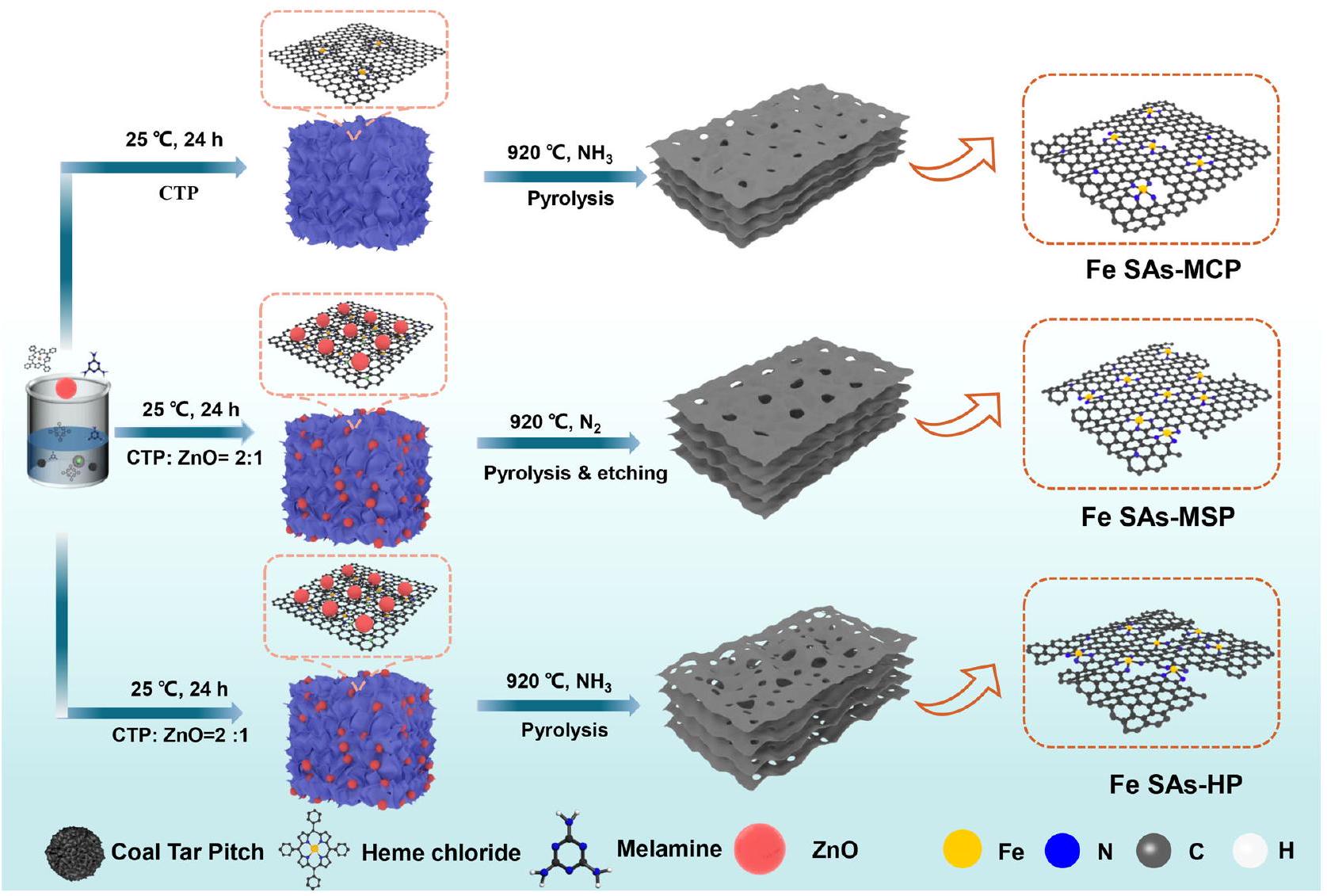
تم تحضير محفزات Fe SAs-HP الموزعة بشكل عالي مع مسام هرمية من خلال استراتيجية التغطية-التحلل الحراري-التبخر تحتالجو كما هو موضح في الشكل 1. هنا، كان كلوريد الهيم مسموح له بالتغلغل في مصفوفة CTP عند درجة حرارة أعلى من نقطة اللينبسبب القوةتفاعل بين كلوريد الهيمتحت درجات حرارة أعلى، القالب اللين،سيتفاعل مع الركيزة الكربونية ويتبخر، مكونًا مواقع حافة مسامية وفيرة لتثبيت ذرات الحديد.. خلال هذه العملية، سيتفاعل أيضًا مع الكربون غير الجرافيتي لتحويله بسهولة إلى أنواع هيدروكربونية، مما يشكل مسام دقيقة في الركائز الكربونية. علاوة على ذلك،يمكن أن تدمج ذرات النيتروجين في الركيزة الكربونية وتحبس ذرات الحديد في المواقع المسامية الدقيقةفي هذا السياق، تم تحقيق محفزات Fe SAs-HP الموزعة بشكل كبير مع وجود ذرات الحديد في المسام الدقيقة والمسامات المتوسطة دون الحاجة إلى عملية غسل حمضية شاقة إضافية. للمقارنة، تم تحضير محفزات Fe SACs الغنية بالمسام المتوسطة (Fe SAs-MSP) أيضًا مع وجود ZnO تحتالغلاف الجوي. تم تخليق SACs الحديدية المهيمنة على الميكرو مسام (Fe SAs-MCP) تحتجو بدون قوالب ZnO. تم أيضًا تحضير SACs الحديدية الخالية من العيوب بدون قالب ZnO تحتالغلاف الجوي (Fe SAs-في المستوى). هيكل المسام ومساحة السطح المحددة وفقًا لبرو ناور-إيميت-تيلر (BET) ) من المحفزات تم الكشف عنها بعناية بواسطة إيزوثيرم الامتزاز-الامتزاز العكسي (الشكل التكميلي 1 والجدول 1). إن السعة الكبيرة للامتزاز لـ Fe SAs-HP وFe SAs-MCP عند ضغط نسبي منخفض تشير إلى وجود العديد من المسام الدقيقة، مما سيسهل استضافة ذرات الحديد. على عكس Fe SAs-MCP، أظهرت Fe SAs-HP وFe SAs-MSP إيزوثيرم من النوع الرابع مع حلقات هيسترسيس H4 عند ضغط نسبي مرتفع. )، مما يشير إلى وجود المسام المتوسطة في Fe SAs-HP. المساحة السطحية المحددة ( ) من Fe SAs-HP زادت من (في SAs-MCP) إلى “، بسبب تكوين المسام في قوالب ZnO القابلة للتضحية. أظهرت توزيع حجم المسام أن Fe SAs-HP أظهر هيكل مسامي هرمي مع توزيع حجم المسام الدقيقة والمتوسطة مركزه عند 0.47 و 30 نانومتر، على التوالي. نسبة مساحة المسام الدقيقةتم استخدامه كمؤشر لقياس تأثير حجم المسام كما هو موضح في الجدول التكميلي 1. كانت المسام الدقيقة والمتوسطة الوفيرة مفيدة لتثبيت ذرات الحديد، مما يعزز التفاعلات بين المراكز النشطة المجاورة.وبالتالي، تم بناء هيكل فريد من نوعه من الحديد (Fe) مع مواقع نشطة (SAs-HP) يحتوي على مسام دقيقة ومسامات متوسطة تتخلل بكثافة في الشبكات الكربونية، مما يمكنه من كشف المواقع النشطة وضمان نقل جيد للكتلة والإلكترونات عند الواجهة.
محتوى الحديد في SACs المحضرة كان، و لـ Fe SAs-HP و Fe SAs-MCP و Fe SAs-MSP و Fe SAs-in plane، على التوالي، كما تم تحديده بواسطة مطيافية الكتلة بالتحليل الطيفي المتصل بالتحريض (ICP-MS، الجدول التكميلي 2). تم زرع ذرات الحديد بشكل ضئيل على أسطح الكربون المخدرة بالنيتروجين الخالية من العيوب (Fe SAs-in plane) بسبب عدم كفاية مواقع التثبيت لتثبيت ذرات الحديد. على العكس من ذلك، وُجد أن ذرات الحديد تفضل التثبيت عند الميكرو مسام وحواف المسام المتوسطة وفقًا لارتفاع محتوى الحديد في Fe SAs-MCP. ) و Fe SAs-MSP ( لذا تم التكهن بوجود هجين من وحدات الحديد الناتجة عن التباين الهيكلي في مواقع الحديد ذات المسام الهرمية، وهي مواقع الحديد المعيبة المحصورة في المسام الدقيقة ومواقع الحديد من نوع الحافة المثبتة عند حواف المسام المتوسطة.. بالإضافة إلى ذلك، كانت محتويات الحديد في Fe SAs-HP (0.72%) أعلى من مجموع Fe SAs-MCP وFe SAs-MSP، مما يشير إلى أن وجود مواقع الحديد في المسام الدقيقة وحواف المسام المتوسطة سيساهم بشكل متبادل في تثبيت ذرات الحديد، مما يحقق وحدة حديد مستقرة. كما تم التحقق من الهيكل المسامي العالي لـ Fe SAs-HP مع المسام الدقيقة والغنية بالمسام المتوسطة من خلال أكبرهم.القيم (1.05) التي تم الكشف عنها بواسطة مطيافية رامان (الشكل التكميلي 2).
أظهرت أنماط حيود الأشعة السينية (XRD) لجميع المحفزات قمتين عريضتين فقط عند و ، والتي تتوافق مع وجوه البلورات (002) و(101) للكربون المgraphitized (الشكل التكميلي 3). لا يمكن ملاحظة أي مرحلة معدنية في SACs الحديدية، مما يشير إلى الهندسة الفعالة لتثبيت ذرات الحديد. تم ملاحظة الشكل والميكروهيكل للمحفزات المحترقة بواسطة المجهر الإلكتروني الماسح (SEM) والمجهر الإلكتروني الناقل (TEM). أظهرت صور TEM في الشكل 2a أن Fe SAs-HP المحضرة حديثًا تقدم هيكلًا ثنائي الأبعاد
الشكل 1 | توضيح تخطيطي لتحضير المحفز. إجراءات التحضير لـ Fe SACs التي تهيمن عليها المسام الدقيقة (Fe SAs-MCP) ، والمسامات المتوسطة (Fe SAs-MSP) ، والمسامات الهرمية للمسام الدقيقة والمسامات المتوسطة (Fe SAs-HP) ، على التوالي.
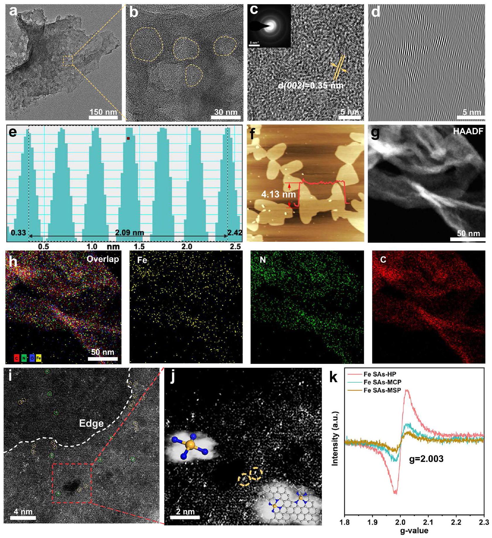
شكل ورقي ثنائي الأبعاد مع سطح مجعد على الحافة، بينما تشير البقع الشفافة إلى خاصية مسامية. تم أيضًا ملاحظة النانوشرائح الفائقة الرقة ثنائية الأبعاد في صور SEM (الشكل التكميلي 4). أكدت صور TEM المكبرة في الشكل 2b الطبيعة المسامية لـ Fe SAs-HP بقطر مسام متوسط.، والذي يمكن أن يُعزى إلى تكوين المسام في ZnO، مما يوفر مواقع حافة وفيرة لتثبيت ذرات الحديد. الصورة المرفقة من حيّز الانتشار الإلكتروني المختار (SAED) في الشكل 2c أظهرت نمطاً حلزونيًا، مما يدل على ضعف بلورية Fe SAs-HP. أظهرت المجهر الإلكتروني الناقل عالي الدقة (HRTEM) بوضوح أوراق الجرافين مع عدة طبقات قليلة. تم تقدير فرقة الشبكة لـ Fe SAsHP لتكون 0.349 نانومتر (الشكل 2d، e)، وهو ما يتماشى مع نتائج XRD ( ) وأعلى من تلك الخاصة بالجرافيت ( 0.335 نانومتر ) بسبب دمج ذرات الحديد. لم يمكن ملاحظة أي جزيئات حديد في المنطقة الكاملة من صور TEM المختارة عشوائيًا، مما يشير إلى التشتت العالي لمكونات الحديد.
تظهر المسح الخطي باستخدام المجهر الذري (AFM، الشكل 2f) أن سمك هذه الأوراق النانوية حوالي 4 نانومتر، مما يكشف أكثر عن الهيكل الشبيه بالجرافين لـ Fe SAs-HP. أشارت المجهر الإلكتروني الناقل ذو الحقل المظلم ذو الزاوية العالية (HAADF-STEM) ورسم الخرائط الطيفية للطاقة المقابلة (EDS) لـ Fe SAs-HP (الشكل 2g، h) إلى أن جزء الحديد كان موزعًا بشكل متجانس في الركائز النيتروجينية الكربونية دون تكتل. لتأكيد الذرات الفردية للحديد الموزعة ذريًا، تم إجراء مجهر إلكتروني ناقل ذو حقل مظلم ذو زاوية عالية مصحح للانحراف (AC-HAADF-STEM). تم اختراق ذرات الحديد في مصفوفة الكربون دون تكتل، مما يدل على طبيعتها الموزعة المعزولة. إلى جانب الحواف المسامية في الشكل 2i، يمكن ملاحظة أزواج الحديد الواضحة عند الحواف المسامية والمواقع الدقيقة (دوائر صفراء). أظهرت الصور المكبرة لـ AC-STEM في الشكل 2j عند المسام المسامية بوضوح وجود أزواج الحديد. تنشأ من التباين الهيكلي. وُجد أن التركيب الإلكتروني لذرات المعدن الفردية قد أعيد توزيعه نتيجة تأثير القرب من ذرات المعدن المجاورة، والذي كان مرتبطًا ارتباطًا وثيقًا بسلوك الامتزاز للوسائط المؤكسدة.. وبالتالي، فإن أزواج الحديد الفريدة مع مواقع الحديد التي تقع في المسام الدقيقة والمسام المتوسطة المجاورة في المحفزات الحديدية ذات المسامية الهرمية قد تعدل التركيب الإلكتروني للمراكز النشطة من خلال تنظيم الإلكترونات على مسافات طويلة وسلوك تحفيزي محسن. كما تم ملاحظة الهيكل غير المنظم للغاية لمواقع الحديد في المحفزات ذات المسامية الهرمية من خلال اختبار الرنين المغناطيسي الإلكتروني (EPR)، حيث كانت لمواقع الحديد في المحفزات ذات المسامية الهرمية أعلى شدة كما هو موضح في الشكل 2k. نفسقيمة المحفزات المسامية المُعدة تؤكد وجود أنواع العيوب المماثلة الموجودة في مصفوفة الكربون الناتجة عن ظروف التصنيع المماثلة..
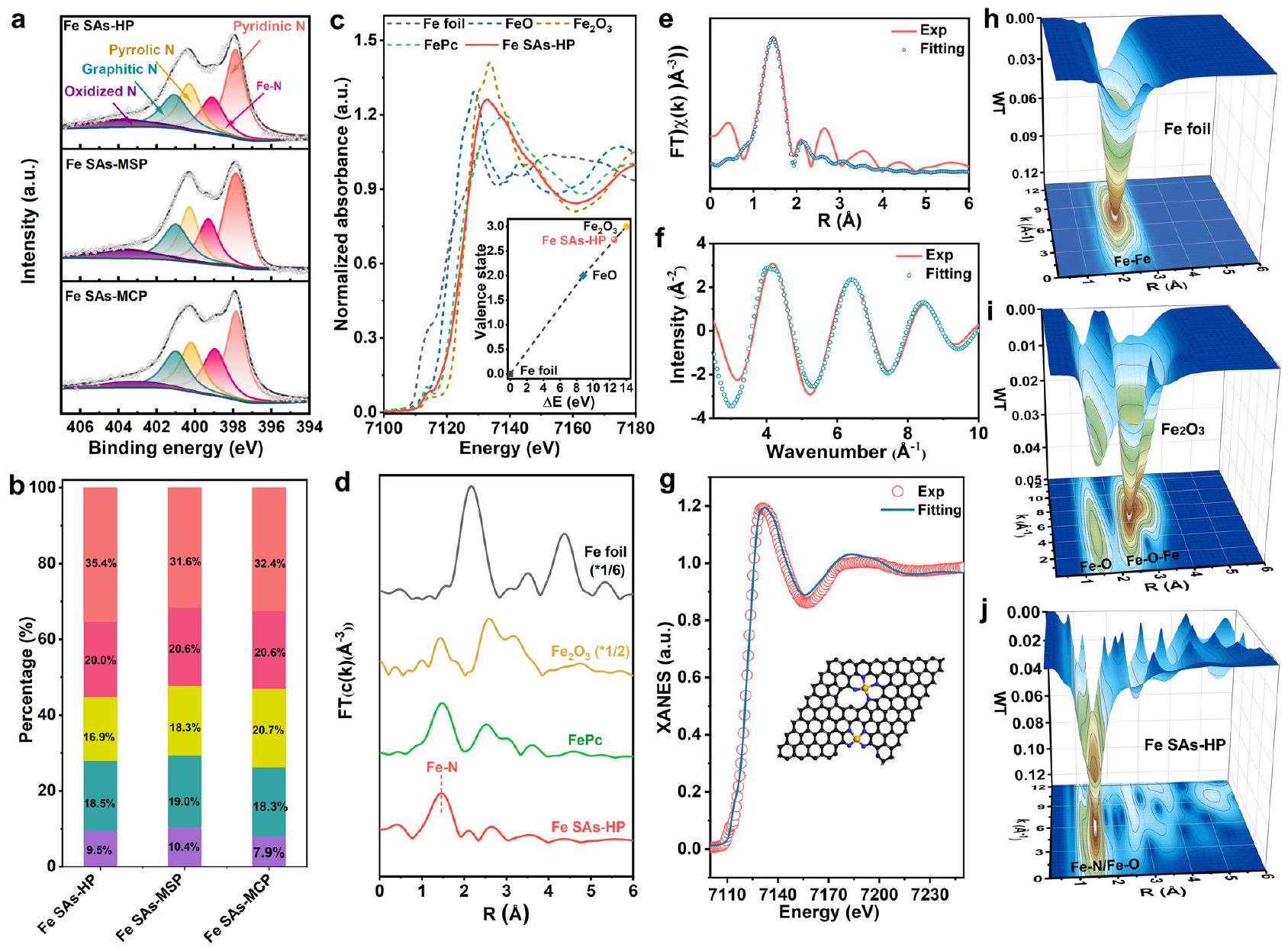
تم إجراء مطيافية الإلكترونات الضوئية بالأشعة السينية عالية الدقة (XPS) لتحديد التركيب العنصري والحالة الكيميائية للمواد المحفزة التي تم إعدادها حديثًا. تم إجراء التحليل عالي الدقةيمكن تحليل الأطياف في الشكل 3أ إلى قمم عندو403.6 إلكترون فولت، والتي يمكن نسبها إلى البيريديني.النيتروجين البيرولي، النيتروجين الجرافيتي، والنيتروجين المؤكسد، على التوالي. من بين أنواع النيتروجين المختلفة، تم التعرف على النيتروجين البيريديني كمسؤول عن توليد النيتروجين المعزول.المواقع، وكان النيتروجين الجرافيتي مواتياً لنقل الإلكترونات في الهيكل الكربونييمكن أن يُعزى المحتوى الكبير من نوع الحافة N كما هو موضح في الشكل 3b إلى وتأثيرات النقش ZnO، التي يمكن أن تسهل تثبيت ذرات الحديد عند المسام الدقيقة وحواف المسام المتوسطة. لاحظ أن أنواع N في جميع عينات Fe SAs لم تتغير تقريبًا كما هو موضح في الشكل 3b، مما يستبعد مساهمتها في النشاط الجوهري لتفاعل اختزال الأكسجين (ORR) لمواقع الحديد.تم إجراء مطيافية امتصاص الأشعة السينية (XAS) لفك شفرة التركيب الإلكتروني والبيئة الكيميائية لـ Fe SAs-HP. ظهر ذروة ما قبل الحافة لهيكل امتصاص الأشعة السينية عند حافة الحديد (XANES) عند 7114 إلكترون فولت، ناتجًا عنإلىالانتقال، جنبًا إلى جنب مع نقل الشحنة من الأسطورة إلى المعدن، الذي
و C. i AC-STEM لـ Fe SAs-HP. الخط المتقطع الأبيض أظهر حافة المسام المتوسطة. الدوائر الصفراء أظهرت أزواج ذرات الحديد عند المسام الدقيقة وحواف المسام المتوسطة، والدوائر الخضراء أظهرت مواقع الحديد التقليدية داخل مصفوفة الكربون. j AC-STEM مكبرة لـ Fe SAs-HP. الصورة المرفقة تظهر التركيب الذري لمواقع الحديد لـ Fe SAs-HP.التحليل الطيفي الإلكتروني للمواد المحفزة المُعدة.
الشكل 2 | توصيفات Fe SAs-HP. أ TEM وصور TEM المكبرة لـ Fe SAs-HP. ج صورة TEM عالية الدقة لـ Fe SAs-HP. الصورة المرفقة هي صورة SAED.الخطوط الشبكية المحللة لـ Fe SAs-HP.صور AFM لـ Fe SAs-HP. تظهر المنحنيات في الزاوية سمك رقائق Fe SAs-HP. صور HAADF-TEM لـ Fe SAs-HP.تداخلات العناصر ورسم الخرائط العنصرية المقابل باستخدام EDS، اعتُبر بصمةً تشبه البورفيرين المسطحمقارنةً بـ FePc الشبيه بالبورفيرين النموذجي، لوحظ انخفاض في شدة الامتصاص لقمة ما قبل الحافة في Fe SAs-HP، مما يشير إلى أن جزء الحديد في Fe SAs-HP شكل بنية مشابهة لـ Fe-N4 مع تشوه.تناظريمكن أن يُعزى التماثل المشوه إلى الهيمنة المشوهةالمواقع المثبتة عند المسام الدقيقة وحواف المسام المتوسطة في Fe SAs-HP. في الوقت نفسه، تم ملاحظة أن عتبة امتصاص الطاقة لـ Fe SAs-HP كانت أعلى من تلك الخاصة بـ FePc بسبب الانتقال إلى طاقة أعلى واقترابها كثيرًا من تلك الخاصة بـكما هو موضح في الشكل 3ج، مما يعني حالة التكافؤ لأنواع الحديد في Fe SAs-HP كانتبدلاً من +2. تم تنفيذ طريقة التركيب الخطي من خلال رسم الطاقة الممتصة عند الحافة وحالة التكافؤ للعينات القياسية للحصول على مزيد من المعلومات حول حالة التكافؤ.تم حساب حالة التكافؤ الدقيقة للحديد في Fe SAs-HP لتكون +2.7، كما هو موضح في الشكل المرفق في الشكل 3c، والذي كان متوافقًا مع نتائج XPS (الشكل التوضيحي 6). قد يُعزى ارتفاع حالة تكافؤ الحديد في Fe SAs-HP مقارنةً بـ FePc النموذجي إلى تأثير قرب موقع الحديد. لذلك، تم إجراء محاكاة لكثافات الشحن التفاضلية لفهم تأثير قرب موقع الحديد بشكل أفضل في
الشكل 3 | خصائص XPS و XAS لـ Fe SAs-HP والمحولات المُعدة. أ XPS للنيتروجينللمحفزات و النسب المقابلة من الأنواع N. الأحمر: نيتروجين بيريديني. الأحمر الداكن: نيتروجين حديدي. الأصفر: نيتروجين بيرولي. السماوي: نيتروجين جرافيتي. الأرجواني: نيتروجين مؤكسد. XANES من حافة الحديد K و d FT-EXAFS للمواد المحفزة التي تم تحضيرها. e، f تجريبي
(Exp) وتركيب Fe SAs-HP في فضاء R وفضاء q، على التوالي. تركيب g XANES لـ Fe SAs-HP. الصورة المرفقة تشير إلى التركيب الذري لـ Fe SAs-HP. h-j WTEXAFS لحافة Fe K لـ Fe foil،، و على التوالي. مسامي هرميحافة مسامية متوسطةتم العثور على مواقع للتبرع بإلكتروناتها للجزيئات المجاورة المسامية.المواقع، مما يؤدي إلى حالة شحن أعلى (الشكل التكميلي 7)كان وجود حالة تكافؤ أعلى لذرات الحديد المركزية مواتياً للتفعيلوتعزيز نقل الإلكترون بين الحديد و نعيتحويل فورييههيكل الامتصاص الممتد للأشعة السينية عند حافة الحديد (EXAFS، الشكل 3d) لحديد SAs-HP أظهر قمة رئيسية عند، مشابه لذلك الخاص بـ FePc، والذي يمكن أن يُعزى إلى القشرة الأولى من مسار تشتت Fe-N. لا يوجد قمة لمسار Fe-Fe عند أكدت بشكل أكبر وجود جزيئات الحديد الموزعة في Fe SAs-HP. تشير التحليلات الكمية لتناسب EXAFS في فضاء R إلى أن عدد تنسيق جزيء الحديد كان حوالي 4، وأن الهيكل التنسيقي الأكثر منطقية كان مواقع النشاط Fe-N4 (الشكل 3e). أظهرت نتائج التناسب الإضافي لـ XANES في الشكل 3g التماثل غير المتناظر.هيكل يحتوي على ذرات الحديد الموجودة في عيوب الميكرو مسام والحواف، وهو ما يتماشى مع نتائج التجارب الخاصة بـ Fe K-edge XANES. تم إجراء تحويل الموجات (WT) لاهتزازات Fe k-edge EXAFS لتأكيد التشتت المعزول لوحدة الحديد. وفقًا لـ FT-EXAFS، يظهر مخطط كونتور WT لـ Fe SAs-HP أقصى كثافة عند حوالي، الذي يتوافق معتشتت (الشكل 3j). بالمقابل، ورقة الحديد وأظهرت العينات القياسية (الشكل 3هـ، و) كثافة أعلى حوالي، والذي يمكن أن يُعزى إلى تشتت الحديد المعدني Fe-Fe. أكدت تحليل XAS التشتت المعزول لـمواقع نشطة ذات هيكل تنسيق غير متماثل بسبب مواقع التثبيت الدقيقة والميكروية غير المتماثلة، والتي كانت تُعتبر عادةً وحدات نشطة لتحفيز الأكسجين الكهربائي..
أداء كهربائي كيميائي تم تقييمه على RDE
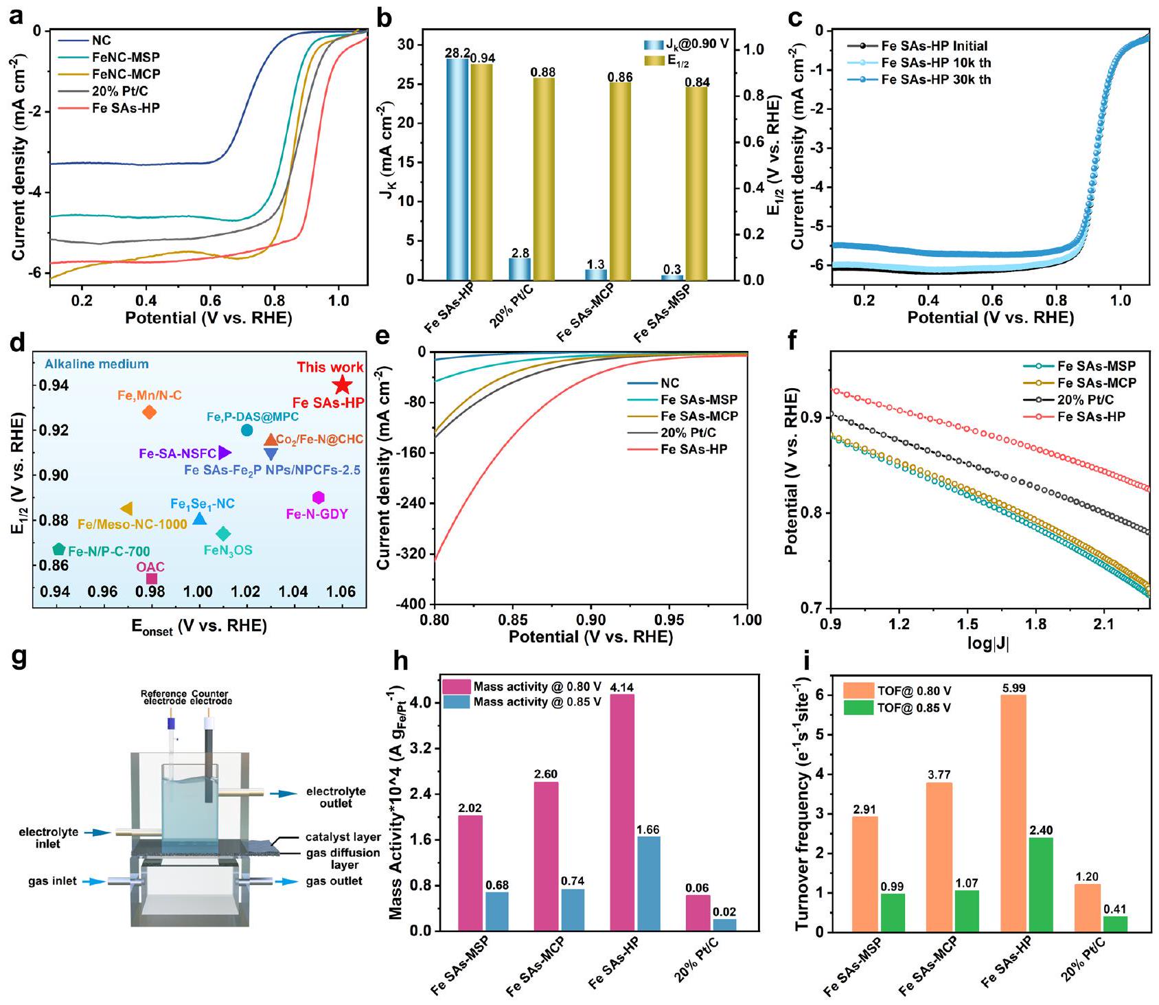
تم إجراء قياسات قطب القرص الدوار (RDE) أولاً لتقدير نشاط اختزال الأكسجين (ORR) للمواد المحفزة التي تم تحضيرها باستخدام نظام ثلاثي الأقطاب نموذجي.-مشبع 0.1 م KOH. تم الإشارة إلى جميع الجهود المقدرة بالنسبة إلى القطب الهيدروجيني القابل للعكس (RHE) ما لم يُذكر خلاف ذلك. بشكل مثير للإعجاب، أظهرت Fe SAs-HP نشاطًا ملحوظًا في اختزال الأكسجين مع جهد بدء قدره 1.06 فولت وجهد نصف الموجة0.94 فولت، كما هو موضح في الشكل 4 أ، والذي تجاوز بكثير قيم المسام الفردية من Fe SAs-MCP (0.86 فولت) وFe SAs-MSP (0.84 فولت)، مما يوضح الدور الهام للهيكل المسامي الهرمي.كان جهد Fe SAs-HP أكثر إيجابية بمقدار 60 مللي فولت مقارنة بالمعيارالمحفزات. بالإضافة إلى ذلك، كانت كثافة التيار الحركي الأعلى أيضًا لـ Fe SAs-HPعند 0.90 فولت كما هو موضح في الشكل 4ب، والذي كان أعلى بمقدار 21.7 مرة من Fe SAs-MCP ) وأعلى بـ 94 مرة من Fe SAs-MSP ( )، مما يدل على نشاطها التحفيزي العالي وتقدمها في هندسة المسام الهرمية. كما تم الكشف عن الديناميات الممتازة لتفاعل اختزال الأكسجين (ORR) لـ Fe SAs-HP من خلال ميلاتها الأقل في تافل كما هو موضح في الشكل التكميلية 8، والذي كان أقل من نظرائهلـ Fe SAs-MCP و Fe SAs-MSP و Pt/C، على التواليتظهر منحنيات السيرة الذاتية لـ Fe SAs-HP ونظرائها بمعدلات مسح تتراوح من 5 إلىتم عرضها في الشكل التوضيحي التكميلي 9. من المدهش أن Fe SAs-MCP تمتلك أعلى سعة كهربائية مزدوجة الطبقة.من، وتبعتها Fe SAs-HP وFe SAs-MSP. أشارت النتائج إلى أن المساحة السطحية النشطة كهربائياً (ECSA) لم تكن الدور السائد في تعزيز نشاط اختزال الأكسجين. مواقع الحديد النشطة الموزعة ذرياً
الشكل 4 | الأداء الكهروكيميائي للمحفزات المحضرة. أ منحنيات LSV للمحفزات المحضرة تحت 0.1 م كOH. ب قلويةعند 0.90 فولت ومن المحفزات. ج اختبارات ADT القلوية لـ Fe SAs-HP. د مقارنة أداء ORR القلوي لـ Fe SAs-HP مع المحفزات المبلغ عنها، على التوالي. هـ منحنيات الاستقطاب للمحفزات المحضرة حديثًا بهياكل مسامية مختلفة بواسطة GDE.مخططات الإمكانيات مقابل
تم التحقق منها أيضًا من خلال اختبارات KSCN بسببالتوافق مع مواقع الحديد المعزولة. أظهرت مواقع الحديد الأحادية في الحالة الصلبة فقدانًا واضحًا في كثافة التيار المحدد وإمكان نصف الموجة، مما يشير إلى أن مواقع الحديد الذرية كانت هي المراكز النشطة (الشكل التكميلي 10). مستلهمين من النشاط الفائق لتفاعل اختزال الأكسجين القلوي لمواقع الحديد الأحادية في الحالة الصلبة، تم أيضًا دراسة نشاط تفاعل اختزال الأكسجين الحمضي للمواد المحفزة التي تم تحضيرها.كما هو موضح في الأشكال التكميلية 11-13. أظهرت Fe SAs-HP خصائص حمضية0.78 فولت، والتي كانت قابلة للمقارنة مع Pt/C (من 0.80 فولت) وكان أفضل بكثير من Fe SAs-MCP (0.68 فولت) و Fe SAs-MSP (بـ 0.60 فولت).
بصرف النظر عن نشاط ORR، فإن الاستقرار والانتقائية للعوامل الحفازة هي أيضًا مؤشرات رئيسية لتقييم الأداء الحفازي. تم إجراء اختبار المتانة المعجل (ADT) واختبارات التيار الزمني الطويل الأمد في كل من 0.1 M KOH ولتقييم استقرار المحفزات المُعدة. أظهرت Fe SAs-HP استقرارًا ضئيلًاتدهور وفقدان جزئي لكثافة التيار المحدد بعد 30,000 دورة ADT في كل من المحلول القلوي والحمضي (الشكل 4c والشكل التكميلي 13)، مما يشير إلى متانتها الاستثنائية وقدرتها على مقاومة الحمض. تم التحقق من المتانة الممتازة من خلال اختبارات التيار الزمني i-t (الشكل التكميلي 14). عرضت Fe SAs-HP نسبة 97.3% معدل الاحتفاظ الحالي بعداختبارات في 0.1 م KOH، متفوقة على تلك الخاصة بـ Fe SAs-MCP )، في ساس-إم إس بي ( ) و Pt/C (58.9%). قد تستفيد المتانة الممتازة لمواقع النشاط في Fe SAs-HP من التفاعلات الإلكترونية القوية بين مواقع الحديد المجهرية والميكروية المجاورة، كما تم التحقق منه من خلال كثافات الشحن التفاضلية وصور AC-STEM. لم يتم رصد أي تغييرات واضحة في شكل Fe SAs-HP بعد 30,000 دورة اختبار (ADT) وفقًا لتوصيفات TEM (الشكل التكميلي 15)، مما يثبت مزايا الهيكل المسامي الفريد. كما شهدت نفس السيناريوهات لـ Fe SAs-HP خلال اختبارات i-t القاسية عند جهد زائد مرتفع قدره 0.2 فولت. ومع ذلك، تم ملاحظة العديد من الكتل الصغيرة وتسرب ملحوظ لذرات الحديد في Fe SAs-MCP وFe SAs-MSP، كما هو موضح في الأشكال التكملية 16 و17 والجدول 3، على التوالي. كانت التفاعلات القوية بين أزواج مواقع الحديد غير المتجانسة المجاورة مفيدة في استقرار ذرات الحديد وتجنب تجمع وهجرة ذرات الحديد النشطة. عدد نقل الإلكتروناتتم حساب Fe SAs-HP استنادًا إلى معادلة كوتيكي-ليفش (K-L). تم تحديد قيم n لـ Fe SAs-HP لتكون 4.02-4.21 في نطاق الجهد من 0.65 إلى 0.85 فولت كما هو موضح في الشكل التكميلية 18. الانتقائية و تم تقدير قياسات عدد الإلكترونات المنقولة بشكل إضافي على قطب كهربائي دائري دوار (RRDE، الشكل التوضيحي 20) في 0.1 م كOH. أظهرت Fe SAs-HP مستوى منخفض منعائد (<5%) عند إمكانيات بعيدة المدى من 0.2 فولت إلى 0.8 فولت وانتقائية عالية لـنسبة الاستجابة الكلية (3.96-4.00)، مما يشير إلى نتيجة إيجابيةمسار ORR على فريدالمواقع النشطة. تم تحديد تأثير عبور الميثانول من خلال حقن الميثانول بشكل فوري في-محلول KOH بتركيز 0.1 م مشبع خلال اختبارات التيار الزمني الكرونوأمبري. عند حقن الميثانول عند 500 ثانية، لم يظهر Fe SAs-HP أي اضطراب في التيار، كما هو موضح في الشكل التكميلي 21، بينما عانى Pt/C من فقدان حاد في التيار، مما يدل على قدرة تحمل الميثانول الممتازة لمواقع الحديد النشطة في Fe SAs-HP. كما أن النشاط الفائق لتفاعل اختزال الأكسجين (ORR) لـ Fe SAs-HP تجاوز أيضًا معظم المحفزات القائمة على الحديد ذات النشاط العالي المبلغ عنها، كما هو موضح في الشكل 4d والشكل التكميلي 22 والجداول 4 و5، حيث يقع نشاط ORR لـ Fe SAs-HP في الزاوية العليا اليمنى من خرائط النشاط في كل من المحاليل القلوية والحمضية. بالمقارنة مع محفزات Fe SAs-MCP وFe SAs-MSP ذات حجم المسام الفردية كما هو موضح في الشكل التكميلي الشامل 23، أظهر Fe SAs-HP نشاطًا محسنًا في ORR، ومتانة، وانتقائية، والتي قد تُعزى إلى تفاعلات مواقع الحديد النشطة الهرمية.
تشجيعًا من النشاط التحفيزي الملحوظ لـ ORR، تم إعداد بطارية سائلة من الزنك-الهواء (ZAB) محلية الصنع للتحقق من التطبيقات الواعدة لمحفز Fe SAs-HP في تكوينات تخزين الطاقة مع Fe SAs-HP كأقطاب هوائية، والزنك كأقطاب سالبة، وكإلكتروليت. للمقارنة، بطاريات الزنك-هواء معتم تجميع المحفزات كأقطاب سالبة أيضًا. قدمت بطارية الزنك-هواء أقصى كثافة طاقة ذروية تبلغعند كثافة تياركما هو موضح في الشكل التكميلية 24، الذي تفوق على المحفز القياسي Pt/Cكانت كثافة القدرة القصوى لبطارية الزنك-هواء المجمعة مع مواقع الحديد الأحادية (Fe SAs-HP) بارزة أيضًا بين بطاريات الزنك-هواء السائلة التي تم الإبلاغ عنها مؤخرًا كما هو موضح في الجدول التكميلي 4.تم تصنيع خلية وقود غشاء تبادل البروتون أيضًا للتحقيق في أداء المحفزات المُعدة كما هو موضح في الشكل التكميلية 25.خلية وقود مع Fe SAs-HP كأقطاب هوائية حققت أقصى كثافة طاقة ذروية منعند كثافة الحالية لـ، والتي كانت أعلى بمقدار 3.2 مرة و 7.6 مرة من تلك الخاصة بـ Fe SAs-MCP ( ) و Fe SAs-MSP ( )، مما يدل على النشاط الفعال لمواقع الحديد الناتجة عن الهيكل المسامي الهرمي.
تقييم نشاط الموقع الداخلي
تكون عملية النقل الكتلي في قياسات RDE محدودة بشدة بسبب ذوبانية الأكسجين في الإلكتروليت، مما يؤدي إلى أداء يتحكم فيه النقل الكتلي. تتيح GDEs نقل المتفاعلات بشكل مشابه لمواقع التفاعل النشطة.. وبالتالي، تم استخدام GDEs محلية الصنع لتقييم MA الجوهري وتردد الدوران (TOF) لمواقع النشاط الحديدي تم تسجيل منحنيات الاستقطاب لجميع العينات على GDE تحت ضوابط صارمة لتدفق الغاز ودرجة الحرارة والرطوبة كما هو موضح في الشكل 4g. عرض الشكل 4e من الفولتموجرامات عملية اختزال خاضعة للتحكم الحركي بشكل نموذجي. زادت كثافة التيار المسجلة لـ Fe SAs-HP بشكل كبير مع زيادة الجهد المطبق. على وجه الخصوص، أظهرت المحفزات NC تيارًا مخفضًا ضئيلًا في اختبارات GDE، مما يشير إلى أن نشاط ORR نشأ بشكل رئيسي من وحدات الحديد. بالإضافة إلى ذلك، أظهرت الرسوم البيانية للجهود مقابل كثافات التيار في الإحداثيات اللوغاريتمية (log J) كما هو موضح في الشكل 4f لـ Fe SACs علاقة خطية عند الجهود من 0.80 فولت إلى 0.90 فولت، مما يشير إلى أن نقل الكتلة للأكسجين كافٍ لتحقيق تيار ORR الحركي النقي المقدم من مواقع الحديد النشطة.
تم اختيار MA وتردد الدوران عند 0.80 فولت و0.85 فولت للوصول إلى نشاط موقع الحديد الجوهري.تم الحصول على MA لـ Fe SACs المُعدة من التيار الظاهر الذي تم تطبيعه بواسطة الوزن الإجمالي لمحتويات الحديد المحملة على GDE استنادًا إلى نتائج ICP-MS. قدمت Fe SAs-HP MA لـعند جهد 0.80 فولت كما هو موضح في الشكل 4 ح، والذي كان 1.6 و 2.0 مرة أعلى من حجم المسام الفرديةو Fe SAs-MSP وملحوظ بين المحفزات غير الثمينة التي تم الإبلاغ عنها مؤخرًا كما هو موضح في الجدول التكميلي. تشير النتائج إلى أن تعتمد نشاط مواقع الحديد الجوهري بشكل كبير على الهندسة لـتمت ملاحظة أن مواقع الحديد الهجينة في Fe SAs-HP، مع مواقع الحديد المثبتة على المسام الدقيقة وحواف المسام المتوسطة، كانت أكثر كفاءة من مواقع الحديد الفردية عند استبعاد عامل نقل الكتلة في اختبارات GDE، وهو ما قد يكون بسبب تحسين المواقع الحديدية الدقيقة والمتوسطة الناتج عن التفاعل بين المواقع.
تم حساب تردد الدوران لفهم كمي لكيفية تأثير تباين مواقع الحديد على النشاط الجوهري. كان TOF يميز عدد الإلكترونات المنقولة لكل موقع نشط في الثانية.. استنادًا إلى التيار الحركي المعدل حسب عدد مواقع الحديد النشطة، يظهر معدل التحويل (TOF) علاقة وثيقة مع هندسة مواقع الحديد. على وجه التحديد، حققت مواقع الحديد الفردية في Fe SAs-HP أعلى نشاط بمعدل تحويل (TOF) قدره موقع عند جهد 0.80 فولت كما هو موضح في الشكل 4i، والذي كان أعلى بمقدار 1.6 مرة و 2.1 مرة من مواقع الحديد في Fe SAs-MCP و Fe SAs-MSP. كما أن النشاط الاستثنائي لموقع Fe SAs-HP تجاوز معظم SACs المبلغ عنها كما هو موضح في الجدول التكميلي.كانت قيمة TOF لـ Fe SAs-HP ممتازة أيضًا مقارنةً بـ Fe SAs-MCP و Fe SAs-MSP عند جهد 0.85 فولت، حيث كانت 2.2 مرة و 2.4 مرة أعلى من تلك الخاصة بالنظائر. أشارت نتائج TOF بقوة إلى أن مواقع الحديد الفردية في Fe SAs-HP كانت أكثر نشاطًا من تلك الموجودة في Fe SAs-MCP و Fe SAs-MSP ذات المسام الفردية، وهو ما يمكن أن يُعزى إلى التفاعلات القوية لمواقع الحديد الناتجة عن التباين الهيكلي في مصفوفة Fe SAs-HP المسامية بشكل هرمي.
أدلة نظرية على تأثير تحفيز التباين الهيكلي
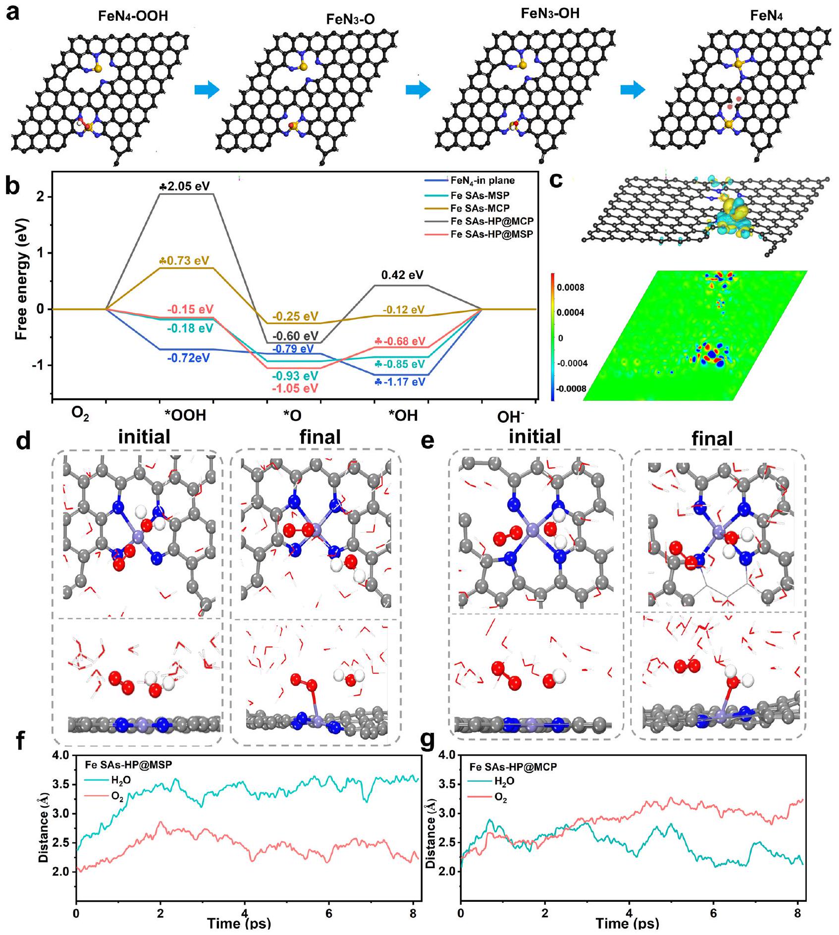
تم إجراء حسابات DFT لفهم تحسين المواقع الفردية للحديد الناتج عن عدم التجانس الهيكلي في مواقع الحديد الأحادية المسامية الهرمية. عدة أنواع منمواقع تشملفي مستوى مصفوفة الكربون (-في الطائرة)، نوع الحافةعند حواف المسام المتوسطة ) و تم اختيار حواف الميكرو مسامية والميزو مسامية (Fe SAs-HP) كنماذج لفهم عملية التحفيز لتفاعل اختزال الأكسجين (ORR) كما هو موضح في الأشكال التكميلية 26-30. بالنظر إلى المحتويات النسبية العالية لمواقع الحديد الميكرو مسامية في Fe SAsMCP، تم أيضًا إجراء تفاعل بين المواقع الفردية لمواقع الحديد الميكرو مسامية كما هو موضح في الشكل التكميلية 28. أظهر سلوك التحفيز لمواقع الحديد ارتباطًا ملحوظًا مع هندستها كما هو موضح في الشكل 5b. تنشيطتبين أنها غير مواتية على مواقع الحديد الميكرو مسامية في Fe SAs-MCP بسبب الطاقة الحرة الصاعدة البالغة 0.73 إلكترون فولت في خطوات ORR الأولى. وتم اعتبار إزالة *OH كخطوة محددة للسرعة (RDS) لمواقع الحديد المسامية من النوع الحدي.ومواقع الحديد الهجينة عند حافة المسام المتوسطة (Fe SAs-HP@MSP). عند، الفرق في الطاقة الحرة لموقع Fe SAsHP@MSP في RDS هو 0.68 إلكترون فولت، وهو أقل من تلك الخاصة بـ-في المستوى (1.17 إلكترون فولت) ومواقع الحديد المسامية الفردية في Fe SAs-MSP (0.85 إلكترون فولت). بالمقارنة، تم حسابه أيضًا في المواقع الميكرو مسامية لـ Fe SAs-HP (Fe SAs-HP@MCP). الخطوة الأولى منتم تحديد التنشيط على المواقع الميكرو مسامية (Fe SAs-HP@MCP) كخطوة محددة للسرعة وأظهر فرق طاقة حرية كبير قدره 2.05 إلكترون فولت، مما كان غير مواتٍ لبدء تفاعل اختزال الأكسجين.مواقع عند الحواف المسامية المتوسطة المجاورة للمسامية الدقيقةلذلك اعتُبرت مواقع نشطة في Fe SAsHP. تم عرض الهيكل المحسن لمواقع الحديد ثنائية التباين في الشكل 5a، حيثرابطة تنتمي إلى المسام الدقيقةالموقع النشط سينكسر إلىهيكل التنسيق بسبب التفاعلات القوية بين المسام الدقيقةوالمسامية المتوسطة. ومع ذلك، فإن الهيكل المحسن لنظام الموقع المزدوج لـ Fe SAs-MCP في الشكل التكميلي 28 ظل بالكاد متغيرًا. كشفت النتائج النظرية الإضافية لكثافات الشحن التفاضلية في الشكل 5c والشكل التكميلي 31 أن مواقع الحديد المجهرية المجاورة ستنظم سلوك الامتصاص للوسائط وتقلل من حواجز التفاعل لـ RDS لمواقع الحديد المسامية، مما يسرع عملية الديناميكا الحركية لـ ORR. بعد امتصاص وسائط *OH، ستفقد ذرات الحديد المركزية عند حواف المسام المفردة وستحصل مجموعات *OH الممتصة على. مختلف عن سيناريو الفردي
مواقع Fe أحادية الذرة (SAs-HP@MSP) ومواقع Fe ميكرو مسامية (Fe SAs-HP@MCP)، على التوالي. f، g المسافة بين مواقع Fe وذرة الأكسجين في الحالة الممتصة (أخضر) و (أحمر) كدالة للزمن في محاكاة AIMD عند 298 كلفن.
الشكل 5 | الحسابات النظرية للمحفزات المُعدة. أ هيكل مُحسّن لـ Fe SAs-HP خلال عملية اختزال الأكسجين. الطاقة الحرة مقابل مسار التفاعل للمواد المحفزة المعدة. ج توزيع الشحنة لـ Fe SAs-HP بعد امتصاص OH. د، هـ التكوين الأولي والنهائي لمحاكاة AIMD لمدة 8 بيكوثانية لمواقع الحديد المسامية (Fe مسامية متوسطةمقدمة عن المسام الدقيقةمجاور للميكرو مسامسوف تنظم سلوك الامتزاز للوسائط *OH. ذرات الحديد المسامية المجاورة للمسام الدقيقةالمواقع ستفقدوتم الحصول عليهالامتصاص الأكثر استقرارًا بكثير منعلى المسام الأحاديةستؤدي المواقع إلى خطوات امتصاص غير مواتية للوسائط *OH. على العكس من ذلك، فإن دمج المسام المجاورة الدقيقةالمواقع ستعمل على تحسين امتصاص * OH على المراكز النشطة وتسهيل تشكيل، الذي كان متسقًا مع مخططات الطاقة الحرة. لذلك،تم التعرف على المواقع في المسام المتوسطة في المواقع الهجينة كمواقع نشطة نتيجة للتعديل الإلكتروني بواسطة المسام الدقيقة المجاورة.المواقع. ستتصرف مجموعات الحديد الأخرى المرتبطة بالميكرو مسام أو حواف المسام المتوسطة كمواقع نشطة تقليدية. تم إجراء تحليل كثافة السكان المداري البلوري المتوقع (COHP) لفهم التفاعل بين *OH لعملية RDS والمراكز النشطة.. ويتم الحصول على COHP المتكامل (ICOHP) من خلال تكامل الطاقة من سالب اللانهاية إلى
مستوى فيمي، حيث توجد علاقة خطية بين ICOHP وتم تحقيقه. قدمت العلاقة الخطية فهماً كميًا لعملية الامتزاز لـعلى الذرات المعدنية المركزية. بالمقارنة مع مواقع الحديد المسامية المفردة ومواقع الحديد الدقيقة (الشكل التكميلي 32)،مرتبط عند الحواف المسامية المتوسطة المجاورة للمسام الدقيقة أظهر امتصاصًا مناسبًا لـ *OH، مما يضمن توازنًا بين النشاط والانفصال.. كشفت النتائج النظرية بوضوح عن التأثير الناتج عن التباين بين المواقع والذي نشأ من التباين الهيكلي، حيث أن المسام الدقيقة كان الموقع موجودًا كموحد لمواقع الحديد المسامية المتوسطة.
تم إجراء محاكاة AIMD للحصول على فهم عميق لسلوك ORR على Fe SAs-HP. تم استخدام نموذج مائع صريح لتقييم التفاعلات بين الصلب والسائل من خلال إدخالوالجزيئات كما هو موضح في الشكل التكميلي 33. بالإضافة إلى ذلك، نظرًا لأن جميع محاكاة AIMD تتم تحت ظروف شحنة ثابتة، يتم تطبيق طريقة استقراء الشحنة التي طورها تشان ونورسكو لتصحيحات الجهد الثابت.. تم استخدام فترة إنتاج مدتها 8 بيكوثانية لتقييم التفاعل بين الحالة الصلبة والسائلة بين المواقع النشطة والمذيبات. تم عرض التكوين الأولي والنهائي لمحاكاة AIMD لمدة 8 بيكوثانية على المواقع المسامية (Fe SAs-HP@ MSP) والمواقع المجاورة الدقيقة المسامية (Fe SAs-HP@MCP) في الشكل 5d و e. كانت المواقع المسامية من الحديد (Fe SAs-HP@ MSP) تميل إلى الامتصاص بشكل تفضيليالجزيئات كما هو موضح في الشكل 5d و f، مما يدل على خطوات تنشيط الأكسجين المواتية وكان متسقًا أيضًا مع طاقات التفاعل الحرة في الشكل 5b. يختلف عن مواقع الحديد المسامية،كانت الجزيئات تميل إلى الامتصاص على مواقع الحديد الميكرو مسامية أثناء الإنتاج بسبب التقصيرالمسافة بين مواقع الحديد والجزيئات كما هو موضح في الشكل 5e، g، مما يدل على ديناميكية ORR أدنى وعملية التنشيط على مواقع الحديد الميكرو مسامية. تذبذبت الطاقة ودرجة الحرارة ضمن نطاق معين، مما يشير إلى أن هيكل نظام مواقع الحديد المزدوجة مستقر خلال عملية اختزال الأكسجين، كما هو موضح في الشكل التكميلية 34، مما يشير إلى أن هيكل نظام مواقع الحديد المزدوجة مستقر خلال عملية اختزال الأكسجين.الموقع على الحافة المسامية المتوسطة في النظام ثنائي المواقع تصرف بشكل أكثر نشاطًا واعتُبر مواقع نشطة خلال عملية اختزال الأكسجين.
استنادًا إلى المحاكاة أعلاه،تم تحديد المواقع على الحواف المسامية المتوسطة كمواقع نشطة في Fe SAs-HP نتيجة للتباين الهيكلي بين المواقع الذي تم تحفيزه بواسطة المسام المجاورة.المواقع. ستعمل مواقع الحديد الميكروية المجاورة كمنظم لمراكز الحديد النشطة المسامية عن طريق تنظيم هيكلها الإلكتروني، مما يسهل تفعيلوإزالة المواد الوسيطة الرئيسية *OH لعملية RDS وتقليل حواجز الطاقة. وبالتالي، تم الكشف عن تحسين المواقع النشطة للحديد الناتج عن تباين الهيكل بين المواقع، والذي يفسر الأصل الهيكلي للنشاط الجوهري المعزز للحديد المسامي بشكل هرمي.المواقع مقارنةً مع SACs الحديدية ذات المسام الفردية.
تحقيق في الآليات الديناميكية على النشاطمواقع
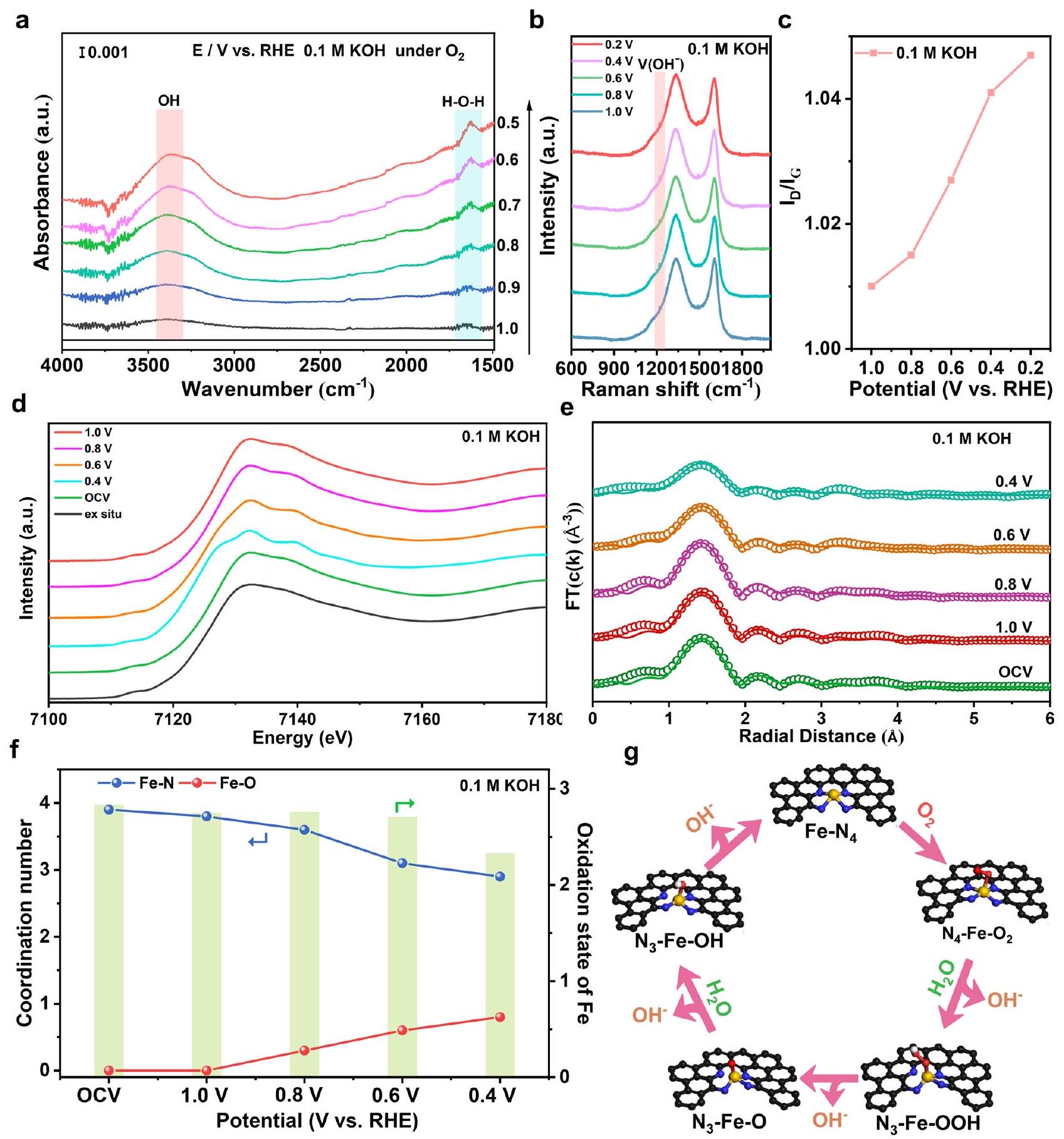
ستحدد التطورات الديناميكية للهيكل السلوك التحفيزي للمراكز النشطة. إن الفهم العميق للتطور الديناميكي للمواد المساميةستوجه المواقع بدورها التصميم العقلاني لأسطح الكاتاليزور الحديدية الفعالة. هنا، بالاقتران مع قياسات ATR-SEIRAS في الموقع، وقياسات رامان في الموقع، وقياسات XAS التشغيلية، تطور الهيكل للمواد المسامية الهرمية.تم إغلاق المواقع. زيادة في شدة الامتصاص عنديمكن ملاحظة الجهود الزائدة المطبقة في قياسات ATR-SEIRAS تحت ظروف العمل في 0.1 M KOH كما هو موضح في الشكل 6a، والذي يمكن أن يُعزى إلى وضع اهتزاز الشد لمجموعة OH الماصة. تشير مجموعات الهيدروكسيل المتراكمة على مواقع الحديد النشطة إلى انسداد عملية إزالة OH، بما يتماشى مع عملية RDS لـ Fe SAs-HP في الحسابات النظرية.. تم أيضًا مراقبة نفس المناسبة تحت ظروف عمل حمضية كما هو موضح في الشكل التوضيحي 35. وذروة متزايدة عنديمكن أن يُعزى إلى وضع اهتزاز الانحناء للهيدروكسيل فيالجزيئات، التي قد تُنسب إلى الامتصاص في الموقعالمتفاعلات في الوسط القلوي والمكونةمنتج تحت وسط حمضي خلال عملية ORR. بالنظر إلى الأدلة المحدودة المقدمة من التوصيف الفردي، تم إجراء قياسات رامان في الموقع أيضًا للكشف عن تطور الهيكل والوسائط الرئيسية. تحت كل من ظروف العمل القلوية والحمضية، تم رصد قمة شديدة تقع عنديمكن أن يُعزى ذلك إلى امتصاص *OH كما هو موضح في الشكل 6b والشكل التكميلي 36، والذي كان متوافقًا مع ملاحظات ATRSEIRAS في الموقع. الإشارات القوية لـ *OH الممتص تشير إلى سلوك تصريف معاق.في عملية RDS. قمة إضافية عندتم ملاحظته في طيف رامان الحمضي في الشكل التكميلية 34، والذي يمكن أن يُنسب إلى امتصاصنسب الكثافة لـفرقةتمت مراقبة قيم Fe SAs-HP لتظهر ميلًا نحو قيم أعلى مع زيادة الجهد الزائد، مما يشير إلى انزياح في مصفوفة الكربون. وقيمة في الوسط القلوي وُجدت القيم أعلى بكثير من تلك في الوسط الحمضي (الشكل 6c والشكل التوضيحي 37)، مما يشير إلى انزياح حاد في الهيكل تحت ظروف العمل القلوية، والذي قد يُعزى إلى كسر رابطة الحديد-النيتروجين. الزيادة الطفيفة فيقد تكون القيمة في المحلول الحمضي ناتجة عن الوسائط المحورية الممتصة، والتي ستدفع ذرات الحديد المركزية خارج مستوى N-4 وتكون الحديد الخماسي التنسيق..
أظهرت النتائج خارج الموقع تشويهاًهيكل التنسيق بحالة تكافؤ +2.7 نتيجة للتنظيم الإلكتروني بواسطة مواقع الحديد المجهرية المجاورة. ومع ذلك، فإن فهم السلوك التحفيزي للنشطةالمواقع ذات الميزات المسامية تحت ظروف العمل ظلت تحديًا. هنا، تم إجراء قياسات XAS أثناء التشغيل (الشكل 6d-f) لتقديم تطور هيكل التنسيق والتحول في حالة التأكسد لمراكز الحديد المسامية النشطة. في 0.1 M KOH، زادت حالة تأكسد الحديد المركزي إلى +2.83 تحت جهد الدائرة المفتوحة (OCV)، وهو ما قد يكون بسبب المجموعات المؤكسدة الماصة مثل أو الجزيئات. وفقًا للتقارير السابقة، كانت حالة التكافؤ الأعلى لذرة الحديد المركزية بسبب المواد المتفاعلة الماصة مسبقًا مواتية لـالتفعيل على مواقع الحديد النشطةمع تطبيق الفائض الكهربائي في بيئة قلوية، تم مراقبة عدد تنسيق الحديد-نيتروجين (CN) ليقل من 3.9 إلى 2.9 (الشكل 6f)، مما يشير إلى حدوث انقطاع فيالرابطة خلال العملية الكهروكيميائية، تتوافق بشكل جيد مع الهيكل المحسن في الحسابات النظرية نتيجة للتفاعلات الإلكترونية القوية بين المسام المتوسطة والصغيرة المجاورة.المواقع. كانت الملاحظات متوافقة جيدًا مع قياسات رامان في الموقع. في نفس الوقت، كانت CN منتم العثور على أن الرابطة تزداد من 0 إلى 0.8، مما يشير إلى تفاعل قوي بين الحديد والأنواع المؤكسدة الماصة. وبالتالي، تطور هيكل النشاطتمت مراقبة المواقع للخضوع لتحول منهيكل التنسيق إلى. في هذه الأثناء، تم تقليل حالة التكافؤ لذرات الحديد المركزية من +2.83 إلى +2.33 بسبب كسر رابطة الحديد-النيتروجين. حالة التكافؤ المنخفضة للذرات المركزية ناتجة عن إعادة بناء ديناميكية للهيكل التنسيقي في المسام الفريدة ذات التسلسل الهرمي.يمكن أن تعمل المواقع على تحسين امتصاص/إطلاق الوسائط المؤكسدة خلال عملية اختزال الأكسجين، مما يفسر مسار تفاعل اختزال الأكسجين المفضل ونشاطها الملحوظ.. يختلف عن السيناريوهات تحت الظروف القلوية، ظل XANES لحافة الحديد K تقريبًا دون تغيير تحت ظروف العمل، مما يشير إلى هيكل تنسيق مستقر لمواقع الحديد كما هو موضح في الأشكال التكميلية 38-40. بالاقتران مع الهيكل التحفيزي المحسن من الحسابات النظرية والقياسات في الموقع/أثناء التشغيل، تطورات الهيكل النشطةكان يُعتقد أن الأجزاء ستخضع لـإلىتبديل الهيكل بسبب التفاعلات القوية لمواقع الزوج الفريدة المسامية المتوسطة والصغيرة في Fe SAs-HP المسامية بشكل هرمي، والتي نظمت سلوكيات التفعيل والامتصاص للمتفاعلات خلال عملية اختزال الأكسجين. تم توضيح الرسم التخطيطي للسلوك الديناميكي لمواقع الحديد المسامية النشطة خلال اختزال الأكسجين في المحاليل القلوية في الشكل 6g.
للمقارنة، تم إجراء تحليل الأشعة السينية في الموقع (Operando XAS) ورامان في الموقع (in situ Raman) لمواقع الحديد المفردة في MCP و MSP لمراقبة سلوك التبديل الديناميكي لمواقع الحديد النشطة. ومن المثير للاهتمام أن سلوكيات التبديل الديناميكي لمواقع الحديد الدقيقة والميكروية كانت
الشكل 6 | التوصيفات في الموقع وفي العمليات لـ Fe SAs-HP في المحاليل القلوية. أ التوصيف في الموقع باستخدام ATR-SEIRAS لـ Fe SAs-HP تحت وسط قلوي. ب، ج طيف رامان في الموقع لـ Fe SAs-HP تم اختباره في 0.1 م KOH والقيم مع الفائض المطبق. د، هـ XANES في حالة التشغيل لحافة الحديد K لـ Fe SAs-HP و تحليل تركيب FT-EXAFS المقابل تحترقم التنسيق المقابل لـ و بالإضافة إلى حالة الأكسدة للحديد تحت ظروف العمل القلوية. تطورات ديناميكية لمواقع الحديد الأحادية تحت ظروف العمل القلوية. مختلفة تمامًا عن بعضها البعض. مع زيادة الجهد الزائد المطبق في البيئة القلوية كما هو موضح في الشكل التكميلي 41 والجدول 9، تم مراقبة عدد تنسيق الحديد (CN) في Fe SAs-MCP ليقل من 3.8 عند جهد الدائرة المفتوحة إلى 1.8 عند الجهود الزائدة الأعلى البالغة 0.4 فولت، مما يشير إلى تطورإلى. في الوقت نفسه، CN للوسائط الممتصة على مواقع الحديد الميكرو مسامية ( لوحظ أنه زاد من 0 إلى 0.5 عند 0.6 فولت. بشكل مثير للإعجاب، جديد يمكن مراقبة مسار التشتت عندأقل من 0.4 فولت كما هو موضح في الشكل التكميلي 39b، مما يشير إلى مسار تشتت FeO. العدد التناسقي لـ و الـ كان الأكسجين الشبكي 6.1 و 3.6 على التوالي.
يرجى ملاحظة أن الرقم القياسي CN لـ و كان 6 و 12، على التوالي. يمكن أن يُعزى CN المنخفض لـ FeO إلى تكوين تجمعات صغيرة.. أظهرت النتائج أن المسام الدقيقةالمواقع كانت تميل إلى الانهيارترتبط وتتجمع في تجمعات صغيرة من FeO تحت جهد زائد أعلى، مما أدى إلى فقدانها لكثافة التيار خلال اختبارات المتانة على المدى الطويل. بالإضافة إلى ذلك، فإن نسب الشدة لـفرقة (تمت ملاحظة أن قيم Fe SAs-MCP تميل إلى الارتفاع مع زيادة الجهد الزائد، مما يدل على انزياح مصفوفة الكربون كما هو موضح في الشكل التوضيحي 42. في حالة Fe SAs-MSP، تم مراقبة التطورات الهيكلية الديناميكية لـ ت undergo تحول منإلىمع زيادة الجهد الزائد المطبق من 1.0 فولت إلى 0.4 فولت كما هو موضح في الشكل التكميلي 43. تم التحقق أيضًا من التشوه الهيكلي الكبير من خلال نتائج رامان في الموقع بسبب الزيادةكما هو موضح في الشكل التكميلية 44. كانت ذرات الحديد غير المشبعة عرضة للوسائط المؤكسدة وقد تتسرب منالطائرة، التي ستسبب فقدانًا كبيرًا في كثافة التيار خلال اختبارات المتانة.
نقاش
باختصار، قمنا بإنشاء محفزات ذرات الحديد المفردة ذات المسام الهرمية مع وجود ذرات الحديد عند حواف المسام الدقيقة والمتوسطة، وحددنا الدور الرئيسي لتأثير التباين الهيكلي بين المواقع في تحسين الأداء التحفيزي. أظهرت محفزات ذرات الحديد المفردة ذات المسام الهرمية نشاطًا متفوقًا في تفاعل اختزال الأكسجين ودوامًا في كل من الوسط القلوي والحمضي. مقارنةً بمحفزات ذرات الحديد المفردة ذات حجم المسام الواحد، قدمت محفزات ذرات الحديد المفردة ذات المسام الهرمية MA عاليًا منونشاط الموقع بسبب تعديل الإلكترون القوي للجزيئات المجاورة المسامية.كشفت حسابات DFT ومحاكاة AIMD عن تأثير التباين الهيكلي بين المواقع، حيث أن المسام الميكرويةكانت المواقع النشطة نتيجة للتنظيم الإلكتروني بواسطة مواقع الحديد المجهرية المجاورة. وجود المسام المجهرية بشكل هرميستساعد المواقع في تسهيل إزالة *OH في RDS وتقليل حواجز التفاعل على المراكز النشطة المجاورة. والأهم من ذلك، بالاقتران مع قياسات ATRSEIRAS في الموقع، ورامان في الموقع، وقياسات XAS أثناء التشغيل، النشطةتمت مراقبة المواقع أثناء إعادة بناء الهيكل الديناميكي منإلىعن طريق كسررابطة في محلول قلوي، مما ساعد على تحسين إزالة الوسطيات. بينما في وسط حمضي، كانت الفعاليةتمت مراقبة المواقع للحفاظ على استقرارها، مما يفسر متانتها الممتازة على المدى الطويل تحت المحاليل الحمضية. تسلط هذه الدراسة الضوء على تحسين الذرات المعدنية المركزية الناتج عن التباين الهيكلي بين المواقع في الهيكل المسامي الهرمي بدقة على المستوى الذري، وتوفر فهماً شاملاً للتطور الديناميكي لمواقع الحديد المسامية، مما يمهد الطريق لتطوير محفزات فعالة للتطبيقات العملية.
طرق
المواد
تم استخدام جميع المواد الكيميائية كما هي دون مزيد من التنقية. الميلامين (AR، كلوريد الهيم (AR، 95%)، هيدروكسيد البوتاسيوم KOH (درجة إلكترونية، 99.999%)، N,N-dimethylformamide (DMF، AR، 99.5%)، أكسيد الزنك ZnO ( ) والسيليكا تم شراءها من شركة شنغهاي علاء الدين للتكنولوجيا الحيوية المحدودة. تم الحصول على CTP من شركة خبي فيتايوان لتكنولوجيا الطاقة المحدودة.
تحضير SAs الحديدية بهيكل المسام الدقيقة (Fe SAs-MCP)
تم تحضير Fe SAs-MCP من خلال عملية التحلل الحراري. في تخليق نموذجي، تم توزيع 1 جرام من CTP و2 جرام من الميلاتونين في 25 مل من DMF تحت التحريك لتشكيل المحلول A. تم توزيع 25 ملغ من كلوريد الهيم في 25 مل من DMF تحت الموجات فوق الصوتية لتشكيل المحلول B. بعد ذلك، تم تشكيل المحلول “تم إضافته قطرة قطرة إلى المحلولوتم التحريك لمدة 24 ساعة. بعد ذلك، تم تسخين المحلول المختلط عندإلى مذيب بخاري. ثم تم تسخين المواد الأولية الناتجة عند درجة حرارةلمدة ساعتين بمعدل تسخين قدرهتحتالجو. قبل عملية التسخين،تم استخدامه لاستبعاد الهواء. تم تصنيف المحفزات المُعدة على أنها Fe SAs-MCP.
تحضير مواقع الحديد الأحادية مع هيكل المسام المتوسطة (Fe SAs-MSP)
مماثل لإجراء التخليق لـتم اختيار 0.5 جرام من ZnO بقطر 30 نانومتر كقالب تضحية وأضيف إلى المحلول A. ثم تم تسخين المواد الأولية الناتجة عند درجة حرارةلمدة ساعتين بمعدل تسخين قدرهتحتالجو. تم تسمية المحفزات التي تم تحضيرها على أنها Fe SAs-MSP.
تحضير مواقع الحديد الأحادية مع مسام هرمية (مواقع الحديد الأحادية-هرمية)
كانت عملية تحضير Fe SAs-HP مشابهة لـ Fe SAs-MCP، باستثناء أنه تم اختيار 0.5 جرام من ZnO بقطر 30 نانومتر كقالب ناعم وإضافته إلى المحلول A. ثم تم تسخين المواد الأولية الناتجة عند درجة حرارةلمدة ساعتين بمعدل تسخين قدرهتحتالجو. تم تسمية المحفزات التي تم تحضيرها على أنها Fe SAs-HP.
القياسات الكهروكيميائية
تم إجراء جميع القياسات الكهروكيميائية على محطة عمل من نوع باين (شركة باين للأجهزة) باستخدام نظام ثلاثي الأقطاب قياسي. تم استخدام القطب الكربوني الزجاجي بقطر 5 مم وقضيب الجرافيت كقطب عمل وقطب مضاد، على التوالي. تم استخدام القطب المرجعي من الزئبق المشبع (SCE) وقطب Ag/AgCl كقطب مرجعي في الوسط القلوي والوسط الحمضي، على التوالي. تم تحضير أحبار المحفزات عن طريق إضافة 5 ملغ من المحفزات إلى 0.5 مل من الإيثانول، الذي يحتوي علىمن wt. نافيونيوم وتبعه التحليل بالموجات فوق الصوتية لمدة ساعة واحدة. تم إجراء القياسات الكهروكيميائية في درجة حرارة الغرفة. عادةً، تم صب حبر المحفز على الأقطاب، وتم الحفاظ على تحميل الكتلة عند. تم استخدام نفس المعيار أيضًا لكتالوج Pt/C التجاري. نقيتم إدخاله في الإلكتروليتات قبل اختبارات ORR. تم الحصول على منحنيات الفولتمترية المسحية الخطية (LSV) لجميع العينات فيمحلول مشبع من 0.1 م كOHبمعدل مسح قدرهمعالتعويضات. تم تعويض المقاومة يدويًا، وتم تحديد المقاومة بواسطة نظام الصنوبر تحت وضع طيف الامتزاز. تم قياس الإلكتروليت بواسطة أجهزة قياس الرقم الهيدروجيني لضمان بيئة اختبار ثابتة.للقلويات وللمتوسطة الحمضية). تم تحويل جميع الجهود المقاسة إلى RHE استنادًا إلى المعادلات:
أين هو الجهد المحتمل مقابل القطب الهيدروجيني القابل للعكس، و هي الجهد المقاس مع SCE وكأقطاب مرجعية. الرقم الهيدروجيني هو تركيز أيون الهيدروجين في الإلكتروليت. I هو قياس التيار، و Rs هو مقاومة المحلول المعوضة.
سعة الطبقة المزدوجة الكهروكيميائيةتم تحديده بمعدل مسح منإلىلاختبارات السيرة الذاتية في النطاق غير فاراداي من 1.11 فولت إلى 1.01 فولت.تم حسابه وفقًا للمعادلات:
أين هو كثافة التيار ( ) و هو معدل المسح ( كثافة التيار الحركي (تم تقييم ( ) وفقًا لمعادلة كوتيكي-ليفش:
أين، و هي كثافة التيار المقاسة، وكثافة التيار المحدودة، وكثافة التيار الحركي، على التوالي. هو السرعة الزاوية لقطب القرص الدوار، هو عدد الإلكترونات المنقولة، هو ثابت فاراداي ( ) ، هو تركيز الكتلة لـهو معامل الانتشار لـفي محلول 0.1 م من هيدروكسيد البوتاسيوم. و،هي اللزوجة الحركية للإلكتروليتتم الحصول على عدد الإلكترونات المنقولة عند إمكانيات مختلفة بواسطة معادلات كوتيكي-ليفش تحت سرعات دوران مختلفة في و . تم تحويل سرعات الدوران إلى سرعة زاوية ( ). العائد وعدد نقل الإلكترون (تُقدّر ) بواسطة المعادلتين (5) و(6) وفقًا لاختبارات RRDE:
أين و هما التيار الحلقي والتيار القرصي، على التوالي.هو كفاءة الجمع الحالية لحلقة البلاتين.
تم إجراء اختبارات متسارعة للمتانة بمعدل مسحمن 1.0 فولت إلى 0.55 فولت (مقابل RHE). تم إجراء اختبارات كرونوأمبريومترية طويلة الأمد على RDE بسرعة دورانعند فولتامترية ثابتة تبلغ 0.75 فولت و0.55 فولت (بالنسبة إلى RHE) لـ تحت وسط قلوي وحمضي، على التوالي. تم إجراء اختبار استقرار قاسي عن طريق تحميل حبر المحفزات المُعدة مسبقًا على ورق الكربون (ورق الكربون Sigracet، 28 BC) عند 0.2 فولت مقابل RHE مع فواتير عالية لمدة 8 ساعات في 0.1 م كOH تحت نظام ثلاثي الأقطاب القياسي. تم الحفاظ على تحميلات الحديد وحجم المحاليل الكهربائية كما هو. تم الحفاظ على تحميلات الحديد عنداستنادًا إلى نتائج ICPMS، تم الاحتفاظ بحجم الإلكتروليت عند 20 مل. بعد اختبار الاستقرار، تم سحب 8 مل من الإلكتروليت، وتمت إضافة إلى الإلكتروليتات لذوبان الأنواع غير القابلة للذوبان من الحديد المحتمل. تم إجراء تحليل ICP-MS لتحديد محتويات الحديد في الإلكتروليتات بعد اختبارات المتانة. للمقارنة، تم استخدام 8 مل من محلول 0.1 م KOH الطازج وتم أيضًا خلطها للكشف عن محتويات الحديد في الإلكتروليتات الطازجة.
تم استخدام ورق الكربون المدمج مع طبقة انتشار الغاز المدعومة على رغوة النيكل (ورق الكربون Sigracet، 28BC) في اختبارات نصف الخلية GDE. للحصول على تحميل متجانس من المحفزات، تم توزيع 5 ملغ من المحفزات المحضرة مسبقًا في 0.5 مل من الإيثانول المحتوي على،من wt. نافييون ثم تم استخدام الموجات فوق الصوتية لمدة ساعة واحدة. بعد ذلك، تم صب حبر المحفزات على GDE. ثم تم نقل GDE مع المحفزات إلى فرن مفرغ عند بعد التجفيف الكامل لمدة 30 دقيقة، تم تقييم المحفزات على تكوين GDE محلي الصنع كما هو موضح في الشكل 4 ج. تم استخدام إلكترود كولوميل المشبع وقضيب الجرافيت كإلكترود مرجعي وإلكترود مضاد، على التوالي. تم ضخ كمية كافية من الأكسجين النقي في الغرفة السفلية بمعدل تدفق، تم التحكم في الرطوبة ودرجة حرارة الإلكتروليت المتدفق عندتم قياس منحنيات الاستقطاب للمواد المحفزة التي تم تحضيرها في محلول 1 م KOH حتى تم ملاحظة منحنيات جهد التنشيط المستقرة. تم تصحيح الجهود إلى RHE مع تعويض IRs كما هو موضح أعلاه.
تم تحديد النشاط الجوهري للعينات المحضرة بواسطة MA و TOF. نظرًا لتوزيع ذرات الحديد المفردة على المستوى الذري والخصائص المسامية لعينات Fe SACs المحضرة، نفترض أن جميع مواقع الحديد تعمل كمواقع متاحة في الحسابات. تم حساب MA للمواد الحفازة بناءً على المعادلات التالية:
أين هو التيار المخفض ( ) المسجلة في قياسات GDE، هو الكتلة المعدنية المحملة (غ) للمواد المحفزة الكهربائية. تم تحديد محتويات المعادن بواسطة ICP-MS.
تم الحصول على TOF للعوامل المساعدة من خلال المعادلات التالية:
أين هو التيار المختزل ( ) المسجلة في قياسات GDE، هو عدد مواقع الحديد الذري التي تم الحصول عليها من ICP-MS، و هو ثابت فاراداي. و منتم تحديده من خلال المتابعة المعادلات وفقًا للأدبيات السابقة:
أين هو تركيز البلاتين في Pt/C، هو تحميل الكتلة من محفز Pt/C على GDE، هو التشتت ( )، و هو الكتلة لكل مول من البلاتين.
توصيفات
تم الكشف عن XRD على جهاز D8 advance (شركة Bruker AXS) باستخدام Cu Kالإشعاع. تم تسجيل أطياف رامان على جهاز Thermo Fisher DXR بطول موجي 532 نانومتر. تم توصيف الشكل والميكروهيكل للمحفزات المحضرة بواسطة TEM (JEM-2100F) و SEM (JSM-7500F). تم إجراء AFM على جهاز Shimadzu SPM-9700. تم الكشف عن التركيب الإلكتروني وحالة التكافؤ للعينات المحضرة بواسطة XPS على جهاز VG ESCALABMK II باستخدام Al K.الإشعاع. تم تحديد هيكل المسام والمساحة السطحية المحددة للعوامل الحفازة بواسطةتم قياس أيزوتروبيات الامتزاز وإزالة الامتزاز على جهاز 3FLEX (Micromeritics Instrument Ltd.). تم الكشف عن محتويات المعادن في المحفزات باستخدام ICP-OES (Thermo Scientific ICAP 6300). تم إجراء قياسات XAFS في محطة 1W1B في منشأة الإشعاع المتزامن في بكين. تم إجراء قياسات XAFS في وضع الفلورية لحدود الحديد K باستخدام كاشف Lytle في خط الأشعة 12B2 في تايوان عند SP-8 (اليابان). تم جمع طيف رامان في الموقع على ميكروسكوب Thermo Fisher DXR2 مع تحفيز ليزري عند 533 نانومتر.الالكتروليتات المشبعة عند درجة حرارة الغرفة. تم جمع تجارب ATR-SEIRAS في الموقع معتمت العملية بدقة و128 مسحًا مدمجًا على الأقل باستخدام مطياف FTIR (Nicolet iS50، Thermo Scientific) مزود بكاشف MCT مبرد بالنيتروجين السائل. تم إجراء القياسات الكهروكيميائية باستخدام جهاز قياس الجهد من برينستون (Princeton Applied Research).
التفاصيل الحاسوبية
لفهم تأثير التباين بين المواقع الناتج عن المسام الهرمية في Fe SAs-HP، تم إجراء الحسابات على آليات ORR باستخدام DFT المطبق في حزمة المحاكاة الأولية فيينا. تم معالجة تأثيرات التبادل والتداخل باستخدام تقريب التدرج العام مع دالة بيردو-بورك-إرنزر-هوف. تم استخدام طريقة الموجات المعززة بالمشاريع لوصف التفاعلات بين الإلكترونات الأساسية وإلكترونات التكافؤ. تم تضمين الموجات المستوية لوظائف الموجات الإلكترونية حتى طاقة قطع تبلغ 500 eV. تم بناء خمسة نماذج هيكلية، بما في ذلك المواقع عند المواقع المسامية الدقيقة والمسامية المتوسطة (Fe SAsHP)، المواقع التي تثبت عند المواقع المسامية الدقيقة (Fe SAs-MCP) أو عند المواقع المسامية المتوسطة (Fe SAs-MSP)، ونوع المواقع التقليدية في المستوى وتم مقارنتها كما هو موضح في الأشكال التكميلية 18-25. تم بناء المواقع عن طريق استبدال ستة ذرات كربون من شريحة الجرافين بواحدة من Fe وأربع ذرات N تثبت عند حواف المسام الدقيقة أو المتوسطة. المسافة بين مواقع Fe المسامية الدقيقة والمتوسطة في Fe SAs-HP هي. تم تطبيق تلطيف غاوسي بقيمة 0.08 eV لتحسين الهندسة وحسابات الطاقة الكلية. تم تعيين معايير التقارب للطاقة والقوة إلى و، على التوالي. تم أخذ عينات من الفضاء العكسي بواسطة شبكة من ( )-نقاط تم إنشاؤها تلقائيًا باستخدام طريقة مونكهورست-باك.
توفر البيانات
البيانات التي تدعم نتائج هذه الدراسة متاحة من المؤلف المقابل عند الطلب.
References
Yang, C. et al. Sulfur-anchoring synthesis of platinum intermetallic nanoparticle catalysts for fuel cells. Science 374, 459-464 (2021).
Lee, C. et al. Grooved electrodes for high-power-density fuel cells. Nat. Energy 8, 685-694 (2023).
Gan, T. & Wang, D. Atomically dispersed materials: ideal catalysts in atomic era. Nano Res. 17, 18-38 (2023).
Xia, C. et al. General synthesis of single-atom catalysts with high metal loading using graphene quantum dots. Nat. Chem. 13, 887-894 (2021).
Shi, X. et al. Precious trimetallic single-cluster catalysts for oxygen and hydrogen electrocatalytic reactions: theoretical considerations. Nano Res. 16, 8042-8050 (2023).
Chen, K. et al. Iron phthalocyanine with coordination induced electronic localization to boost oxygen reduction reaction. Nat. Commun. 11, 4173 (2020).
. et al. Tailoring sites with edge enrichment for boosted oxygen reduction performance in proton exchange membrane fuel cell. Adv. Energy Mater. 9, 1803737 (2019).
Sheng, J., Sun, S., Jia, G., Zhu, S. & Li, Y. Doping effect on mesoporous carbon-supported single-site bifunctional catalyst for zincair batteries. ACS Nano 16, 15994-16002 (2022).
Wang, Y. D. et al. Large-scale physically accurate modelling of real proton exchange membrane fuel cell with deep learning. Nat. Commun. 14, 745 (2023).
Liu, J. et al. A brief history of zinc-air batteries: 140 years of epic adventures. Energ. Environ. Sci. 15, 4542-4553 (2022).
Zhou, T. et al. Nanopore confinement of electrocatalysts optimizing triple transport for an ultrahigh-power-density zinc-air fuel cell with robust stability. Adv. Mater. 32, 2003251 (2020).
Zhang, Q. et al. Covalent organic framework-based porous ionomers for high-performance fuel cells. Science 378, 181-186 (2022).
Yang, J. et al. Dynamic behavior of single-atom catalysts in electrocatalysis: identification of as an active site for the oxygen reduction reaction. J. Am. Chem. Soc. 143, 14530-14539 (2021).
Xing, G. et al. Reconstruction of highly dense Cu-N4 active sites in electrocatalytic oxygen reduction characterized by operando synchrotron radiation. Angew. Chem. Int. Ed. 61, e20211098 (2022).
Jia, Q. et al. Experimental observation of redox-induced switching behavior as a determinant role for oxygen reduction activity. ACS Nano 9, 12496-12505 (2015).
Zhang, J. et al. Novel ( )-( ) nonbonding active structures on defective carbon from oxygen-rich coal tar pitch for efficient HER and ORR. Adv. Mater. 34, 2206960 (2022).
Li, H. et al. Highly dispersed NiO clusters induced electron delocalization of NiNC catalysts for enhanced electroreduction. Adv. Funct. Mater. 33, 2208622 (2023).
Sun, G. et al. Atomic coordination structural dynamic evolution of single-atom Mo catalyst for promoting activation in slurry phase hydrocracking. Sci. Bull. 68, 503-515 (2023).
Wan, W. et al. Bifunctional single atom electrocatalysts: coordination-performance correlations and reaction pathways. ACS Nano 14, 13279-13293 (2020).
Sun, T. et al. Engineering of coordination environment and multiscale structure in single-site copper catalyst for superior electrocatalytic oxygen reduction. Nano Lett. 20, 6206-6214 (2020).
Li, Z. et al. Single-atom Zn for boosting supercapacitor performance. Nano Res. 15, 1715-1724 (2022).
Zhao, J. et al. Spatial confinement of zeolitic imidazolate framework deposits by porous carbon nanospheres for dual-atom catalyst towards high-performance oxygen reduction reaction. Nano Res. 16, 11464-11472 (2023).
Jaouen, F., Lefèvre, M., Dodelet, J. & Cai, M. Heat-treated Fe/N/C catalysts for electroreduction: are active sites hosted in micropores? J. Phys. Chem. B 110, 5553-5558 (2006).
Yang, L. et al. Atomic in flexible carbon fiber membrane as binder-free air cathode for Zn -air batteries with stable cycling over 1000 h. Adv. Mater. 34, 2105410 (2022).
Jin, Z. et al. Understanding the inter-site distance effect in singleatom catalysts for oxygen electroreduction. Nat. Catal. 4, 615-622 (2021).
Zong, L. et al. Anchoring single copper atoms to microporous carbon spheres as high-performance electrocatalyst for oxygen reduction reaction. Adv. Funct. Mater. 31, 2104864 (2021).
Li, M. et al. Proximity electronic effect of Ni/Co diatomic sites for synergistic promotion of electrocatalytic oxygen reduction and hydrogen evolution. Adv. Funct. Mater. 33, 2210867 (2023).
Jia, Y. & Yao, X. Defects in carbon-based materials for electrocatalysis: synthesis, recognition, and advances.Acc. Chem. Res. 56, 948-958 (2023).
Wang, X. et al. Identifying the key role of pyridinic-N-Co bonding in synergistic electrocatalysis for reversible ORR/OER. Adv. Mater. 30, 1800005 (2018).
Chen, S . et al. Identification of the highly active coordination motif for selective oxygen reduction to hydrogen peroxide. J. Am. Chem. Soc. 144, 14505-14516 (2022).
Sun, J. et al. Ultrathin nitrogen-doped holey carbon@graphene bifunctional electrocatalyst for oxygen reduction and evolution reactions in alkaline and acidic media. Angew. Chem. 130, 16749-16753 (2018).
Li, L. et al. Single-atom Fe- catalyst for high-performance zinc-air batteries. Nano Res. 15, 8056-8064 (2022).
Zhou, W. et al. Regulating the scaling relationship for high catalytic kinetics and selectivity of the oxygen reduction reaction. Nat. Commun. 13, 6414 (2022).
Luo, F. et al. Regulated coordination environment of Ni single atom catalyst toward high-efficiency oxygen electrocatalysis for rechargeable zinc-air batteries. Energy Storage Mater. 35, 723-730 (2021).
Xiao, M. et al. Preferentially engineering edge sites onto graphitic nanosheets for highly active and durable oxygen electrocatalysis in rechargeable Zn-air batteries. Adv. Mater. 32, 2004900 (2020).
Wang, L. et al. Periodic one-dimensional single-atom arrays. J. Am. Chem. Soc. 144, 15999-16005 (2022).
Fan, J. et al. Bridging the gap between highly active oxygen reduction reaction catalysts and effective catalyst layers for proton exchange membrane fuel cells. Nat. Energy 6, 475-486 (2021).
Zalitis, C. M., Kramer, D. & Kucernak, A. R. Electrocatalytic performance of fuel cell reactions at low catalyst loading and high mass transport. Phys. Chem. Chem. Phys. 15, 4329-4340 (2013).
Zhu, X. et al. Intrinsic ORR activity enhancement of Pt atomic sites by engineering the d -band center via local coordination tuning. Angew. Chem. 133, 22082-22088 (2021).
Su, H. et al. Dynamic evolution of solid-liquid electrochemical interfaces over single-atom active sites. J. Am. Chem. Soc. 142, 12306-12313 (2020).
Zhou, Y. et al. Multilayer stabilization for fabricating high-loading single-atom catalysts. Nat. Commun. 11, 5892 (2020).
Chan, K. & Nørskov, J. K. Electrochemical barriers made simple. J. Phys. Chem. Lett. 6, 2663-2668 (2015).
Chan, K. & Nørskov, J. K. Potential dependence of electrochemical barriers from ab Initio calculations. J. Phys. Chem. Lett. 7, 1686-1690 (2016).
Zhang, P. et al. Bifunctional single atom catalysts for rechargeable zinc-air batteries: from dynamic mechanism to rational design. Adv. Mater. 35, 2303243 (2023).
Wei, J. et al. Probing the oxygen reduction reaction intermediates and dynamic active site structures of molecular and pyrolyzed Fe-N-C electrocatalysts by in situ raman spectroscopy. ACS Catal. 12, 7811-7820 (2022).
Li, X. et al. Identification of the electronic and structural dynamics of catalytic centers in single-Fe-atom material. Chem 6, 3440-3454 (2020).
Wang, Y., Tang, Y. & Zhou, K. Self-adjusting activity induced by intrinsic reaction intermediate in Fe-N-C single-atom catalysts. J. Am. Chem. Soc. 141, 14115-14119 (2019).
Hutchison, P., Rice, P. S., Warburton, R. E., Raugei, S. & HammesSchiffer, S . Multilevel Computational studies reveal the importance of axial ligand for oxygen reduction reaction on Fe-N-C materials. J. Am. Chem. Soc. 144, 16524-16534 (2022).
Matos, J. et al. In situ coarsening study of inverse micelle-prepared Pt nanoparticles supported on : pretreatment and environmental effects. Phys. Chem. Chem. Phys. 14, 11457 (2012).
Kresse, G. & Furthmüller, J. Efficiency of ab-initio total energy calculations for metals and semiconductors using a plane-wave basis set. Comp. Mater. Sci. 6, 15-50 (1996).
Kresse, G. & Furthmuller, J. Efficient iterative schemes for ab initio total-energy calculations using a plane-wave basis set. Phys. Rev. B Condens Matter 54, 11169-11186 (1996).
Perdew, J. P., Burke, K. & Wang, Y. Generalized gradient approximation for the exchange-correlation hole of a many-electron system. Phys. Rev. B Condens Matter 54, 16533-16539 (1996).
Fernández-Torre, D., Carrasco, J., Ganduglia-Pirovano, M. V. & Pérez, R. Hydrogen activation, diffusion, and clustering on (111): A DFT+U study. J. Chem. Phys. 141, 014703 (2014).
Monkhorst, H. J. & Pack, J. D. Special points for Brillouin-zone integrations. Phys. Rev. B 13, 5188-5192 (1976).
الشكر والتقدير
تم دعم هذا العمل من قبل برنامج علماء تايشان في مقاطعة شاندونغ (رقم tsqn201909065)، مؤسسة العلوم الطبيعية الوطنية في الصين (رقم 22108306)، مؤسسة العلوم الطبيعية في مقاطعة شاندونغ (ZR2021YQ15)، صناديق البحث الأساسية للجامعات المركزية (22CX07009A)، مركز هيفي الوطني للبحث في العلوم الفيزيائية على المقياس المجهري (KF2021107)، المختبر الوطني الرئيسي للمركبات العضوية وغير العضوية (oic-202101006).
مساهمات المؤلفين
صمم P.Z. وY.P. المشروع، وكتبوا المخطوطة. أعد P.Z. عينات المحفز، واختبر أداء ORR، وميز العينات، وحلل البيانات، وكتب الأقسام المقابلة. اختبر H.C. وP.Z. تجارب رامان في الموقع وتجربة EXAFS العملية وحللا جميع بيانات XANES وEXAFS. أجرى H.Z. وT.L. و
P.Z. حسابات DFT، وحللوا بيانات الحساب، وكتبوا القسم المقابل. توقع K.C. وY.Z. وJ.L. وS.H. إعداد المحفزات. قام R.H. وW.Z. بتجميع واختبار بطاريات الزنك-الهواء وPEMFC. أشرف Y.P. وY.L. على المشروع، ووجهوا البحث، وأسسوا النسخة النهائية من المخطوطة. ساهم P.Z. وH.C. وH.Z. بالتساوي في هذا العمل.
المصالح المتنافسة
يعلن المؤلفون عدم وجود مصالح متنافسة.
معلومات إضافية
المعلومات التكميلية النسخة الإلكترونية تحتوي على
المواد التكميلية المتاحة على https://doi.org/10.1038/s41467-024-46389-3.
يجب توجيه المراسلات وطلبات المواد إلى يوان تشي ليو أو يوان بان.
تقدير مراجعة الأقران تود ناتشر كوميونيكيشنز شكر بوسرا ديرلي تشاغلايان والمراجعين الآخرين المجهولين على مساهمتهم في مراجعة الأقران لهذا العمل. يتوفر ملف مراجعة الأقران.
المختبر الرئيسي للدولة لمعالجة النفط الثقيل، جامعة الصين للبترول (شرق الصين)، كينغداو 266580، الصين. مركز علوم وتقنيات الاعتمادية، جامعة تشانغ غونغ، تاويون 33302، تايوان. مركز أبحاث الكلى، قسم أمراض الكلى، مستشفى تشانغ غونغ التذكاري، لينكو، تاويون 33305، تايوان. كلية علوم وهندسة المواد، جامعة الصين للبترول (شرق الصين)، كينغداو 266580، الصين. المختبر الرئيسي للدولة للمركبات العضوية وغير العضوية، جامعة بكين للتكنولوجيا الكيميائية، بكين 100029، الصين. هؤلاء المؤلفون ساهموا بالتساوي: بينغ زانغ، شياو-تشيان تشين، هوي يو زو. البريد الإلكتروني:liuyq@upc.edu.cn; panyuan@upc.edu.cn
Inter-site structural heterogeneity induction of single atom Fe catalysts for robust oxygen reduction
Received: 19 September 2023
Accepted: 23 February 2024
Published online: 07 March 2024
Check for updates
Abstract
Peng Zhang , Hsiao-Chien Chen , Houyu Zhu , Kuo Chen , Tuya Li , Yilin Zhao , Jiaye Li , Ruanbo Hu , Siying Huang , Wei Zhu , Yunqi Liu Yuan Pan
Abstract
Metal-nitrogen-carbon catalysts with hierarchically dispersed porosity are deemed as efficient geometry for oxygen reduction reaction (ORR). However, catalytic performance determined by individual and interacting sites originating from structural heterogeneity is particularly elusive and yet remains to be understood. Here, an efficient hierarchically porous Fe single atom catalyst (Fe SAs-HP) is prepared with Fe atoms densely resided at micropores and mesopores. Fe SAs-HP exhibits robust ORR performance with half-wave potential of 0.94 V and turnover frequency of at 0.80 V . Theoretical simulations unravel a structural heterogeneity induced optimization, where mesoporous acts as real active centers as a result of long-range electron regulation by adjacent microporous sites, facilitating activation and desorption of key intermediate *OH. Multilevel operando characterization results identify active Fe sites undergo a dynamic evolution from basic to active under working conditions. Our findings reveal the structural origin of enhanced intrinsic activity for hierarchically porous sites.
Ever-growing concerns about energy and environmental issues call for clean energy. Fuel cells and metal-air batteries represent promising candidates for the next generation of energy conversion and storage system due to their high energy density, low cost, eco-friendliness, etc . The development of such advanced energy conversion configurations, however, is hampered by sluggish oxygen reduction reaction (ORR) kinetics and the high cost of precious metal catalysts at air cathodes. The emergency of single-atom catalysts (SACs) with high atom utilization and tunable active sites has reinvigorated intense attention for addressing activity, durability, and high costs of noble metal-based catalysts . Among various SACs, Fe-N4 sites with welldefined porphyrin-like structures are generally considered the most active and selective elelctrocatalysts for ORR. However, adsorption
and activation were impeded due to symmetric electron distribution of well-defined structure . Great endeavors have been devoted to exploiting efficient Fe SACs with asymmetric coordination structure, such as edge-type , etc . Despite great progress being made so far, it was soon discovered the performance of batteries was beyond the electrocatalyst matters. Since the ORR took place at a triple-phase interface, the geometric structure of electrocatalysts will also greatly affect electron and mass transport . Generally, mesoporous structure was considered to guarantee a fast mass transport, and microporous structure promoted faster shutting of electrons and contributed to resisting the intrusion of water during . Thereafter, SACs with hierarchically porous structure were regarded as an efficient geometry for ORR. While several studies have
been carried out to construct efficient SACs with hierarchical porous structure, little work has established a relationship between individual intrinsic activity and structure due in part to a mass transportcontrolled process provided by rotation disk electrode. Additionally, the rational design of efficient SACs for ORR also relies heavily on basic understanding of catalytic under working conditions at atomic precise. In general, the dynamic switching behavior of SACs was sensitive to coordinative environment, even for the same central metal-based . For instance, Fe-N-C moiety in the plane of carbon-nitrogen matrix might undergo three dynamic modes by monitoring the central Fe atoms moving towards or away from N-4 plane in relation to the pyrolysis temperature and geometric structure of sites . The dynamic structure was found to essentially govern ORR activities. Therefore, an extensive comprehension of the relationship between structure and intrinsic activity, as well as identifying dynamic evolution of active centers, is highly desirable but remained a great challenge.
Here we demonstrate a comprehensive understanding of hierarchically porous sites for ORR in combination with experimental and theoretical methods. By engineering the pore structure of sites, it allowed one to determine catalytic behavior of individual sites along with structural heterogeneity induced effect. Coal tar pitch (CTP), composed of polycyclic aromatic hydrocarbons (PAH), was regarded as high-quality carbon resource and has been widely used in the field of energy storage and conversion systems due to its high conductivity and structure flexibility . Herein, an encapsulation-pyrolysis-evaporation strategy was developed to prepare hierarchically porous Fe SACs (Fe SAs-HP) immobilized on CTP-derived carbon substrates. Naturally, heme chloride was carefully selected as Fe source due to strong – interactions between heme chloride macrocycle and PAH, which was conducive to evenly dispersing Fe atoms into carbon networks and avoiding the agglomeration of undesirable metallic iron nanoparticles. ZnO, sacrificial templates, and atmosphere were allowed to react with carbon substrate under high temperatures to form abundant mesoporous edges and micropores to immobilize Fe atoms, forming active Fe moieties.
Hierarchically porous Fe SAs-HP exhibited remarkable ORR activity with half-wave potential ( ) of 0.94 V and excellent longterm durability for 30 k cyclic voltammetry (CV) cycles in alkaline media. In addition, the superior catalytic performance of Fe SAs-HP was also witnessed by the high mass activity (MA) and turnover frequency ( site ) obtained from gas diffusion electrode (GDE), which far outperformed those of single poresized Fe SACs. In combination with density functional theory (DFT) and ad initio molecular dynamics (AIMD), an inter-site structural heterogeneity-induced effect was revealed, where sites at mesoporous edges behave as real active sites as a result of electronic modulation of adjacent microporous Fe sites. In situ attenuated total reflectance surface-enhanced infrared absorption spectroscopy (ATR-SEIRAS), in situ Raman and operando XAS measurements provided a thorough understanding of dynamic ORR mechanism on active porous sites, which underwent a dynamic evolution by breaking Fe-N bond in alkaline medium and therefore lowering reaction barriers. The strong interactions between adjacent pairs of structural heterogeneity Fe sites also contributed to the stabilization of Fe atoms, avoiding the aggregation and migration of active Fe atoms. These findings legitimate rational optimization of SACs by pore structure engineering and provide an in-depth understanding of dynamic ORR mechanism on porous single Fe sites, which might promote the use of SACs in practical applications.
Results
Identifying Fe SACs with different pore structure
Highly dispersed Fe SAs-HP catalysts with hierarchical pores were prepared through an encapsulation-pyrolysis-evaporation strategy under atmosphere as shown in Fig. 1. Here, heme chloride was
allowed to permeate into CTP matrix under a temperature higher than softening point ( ) due to strong conjugation between heme chloride and . Under higher temperature, the soft template, , would react with carbon substrate and evaporate, forming abundant mesoporous edge sites to immobilize Fe atoms . During this process, would also react with nongraphitic carbon to readily convert into hydrocarbon species, forming micropores in carbon substrates. Moreover, could incorporate N atoms into carbon substrate and trap Fe atoms in the microporous sites . Herein, highly dispersed Fe SAs-HP catalysts with Fe atoms resided at microcpores and mesopores were achieved without further tedious acid washing process. For comparison, mesoporous-rich Fe SACs (Fe SAs-MSP) was also prepared with the existence of ZnO under atmosphere. Micropore-dominated Fe SACs (Fe SAs-MCP) were synthesized under atmosphere without ZnO templates. Particularly, defect-free Fe SACs were also prepared without ZnO template under atmosphere (Fe SAs-in plane). Pore structure and Brunauer-Emmett-Teller (BET) specific surface area ( ) of catalysts were then carefully revealed by adsorption-desorption isotherms (Supplementary Fig. 1 and Table 1). The large adsorption capacity of Fe SAs-HP and Fe SAs-MCP at low relative pressure suggested the existence of plentiful micropores, which would facilitate to host Fe atoms. Different from Fe SAs-MCP, Fe SAs-HP, and Fe SAs-MSP exhibited a typical type-IV isotherms with H4 hysteresis loops at high relative pressure ( ), indicating the co-existence of mesopores in Fe SAs-HP. Specific surface area ( ) of Fe SAs-HP increased from (Fe SAs-MCP) to , due to the porogenesis of ZnO sacrificial templates. Pore size distribution demonstrated that Fe SAs-HP exhibited a hierarchical pore structure with micropore and mesopore size distribution centered at 0.47 and 30 nm , respectively. The proportion of micropore area was used as an indicator to quantify the effect of pore size as shown in Supplementary Table 1. Plentiful micropores and mesopores were conducive to immobilizing Fe atoms, strengthening the interactions of adjacent active centers . Thus, the unique Fe SAs-HP with micropores and mesopores densely permeating in the carbon networks was constructed, which could expose active sites and guarantee decent mass and electron transfer at interface.
The Fe contents of as-prepared Fe SACs were , and for Fe SAs-HP, Fe SAs-MCP, Fe SAs-MSP, and Fe SAs-in plane, respectively, as determined by inductively coupled plasma mass spectrometry (ICP-MS, Supplementary Table 2). Negligible Fe atoms were planted on defect-free nitrogen-doped carbon planes (Fe SAs-in plane) due to insufficient anchoring sites to immobilize Fe atoms. On the contrary, Fe atoms were found to preferentially anchor at micropores and mesoporous edges according to higher Fe contents of Fe SAs-MCP ( ) and Fe SAs-MSP ( . A hybrid of Fe moieties stemming from structural heterogeneity was therefore speculated to exist in hierarchically porous Fe SAs-HP, namely defective Fe sites confined in micropores and edge-type Fe sites anchored at mesoporous edges . In addition, Fe contents of Fe SAs-HP (0.72%) were higher than the sum of Fe SAs-MCP and Fe SAs-MSP, suggesting the co-existence of Fe sites at micropores and mesoporous edge would mutually promote the immobilization of Fe atoms, achieving a stable Fe moiety. The highly porous structure of Fe SAs-HP with rich micropores and mesopores was also verified by their largest values (1.05) detected by Raman spectroscopy (Supplementary Fig. 2).
X-ray diffraction patterns (XRD) of all the catalysts showed only two broad peaks at and , corresponding to (002) and (101) crystal faces of graphitized carbon (Supplementary Fig. 3). No metallic phase can be observed in Fe SACs, indicating the efficient geometry to anchor Fe atoms. The morphology and microstructure of pyrolyzed catalysts were observed by scanning electron microscopy (SEM) and transmission electron microscopy (TEM). The TEM images in Fig. 2a showed that the as-prepared Fe SAs-HP presents a two-dimensional
Fig. 1 | Schematic illustration of catalyst preparation. Preparation procedures for Fe SACs dominated by micropores (Fe SAs-MCP), mesopores (Fe SAs-MSP), and hierarchical pores of micropores and mesopores (Fe SAs-HP), respectively.
(2D) sheet-like morphology with a wrinkled surface on the edge, while the transparent spots indicate porous feature. The 2D ultrathin nanosheets were also observed in SEM images (Supplementary Fig. 4). The magnified TEM images of Fig. 2b confirmed the porous nature of Fe SAs-HP with a mesopore diameter of , which could be attributed to the porogenesis of ZnO , providing abundant edge sites for immobilizing Fe atoms. The inset image of selected area electron diffraction (SAED) in Fig. 2c exhibited a ring-like pattern, indicating poor crystallinity of Fe SAs-HP. High-resolution transmission electron microscopy (HRTEM) clearly showed the graphene sheets with several few layers. The lattice fringe of Fe SAsHP was estimated to be 0.349 nm (Fig. 2d, e), which was in line with XRD results ( ) and higher than that of graphite ( 0.335 nm ) due to incorporation of Fe atoms. No iron particles could be observed at the whole region of randomly selected TEM images, indicating the high dispersion of Fe moieties.
Atomic force microscopy (AFM, Fig. 2f) linear scan demonstrates that the thickness of these nanosheets is about 4 nm , further revealing the ultrathin graphene-like structure of Fe SAs-HP. High-angle annular dark-field scanning transmission electron microscopy (HAADF-STEM) and corresponding energy dispersive spectrometer (EDS) mapping of Fe SAs-HP (Fig. 2g, h) indicated the Fe moiety was homogeneously dispersed into nitrogen-carbon substrates without agglomeration. To further confirm the atomically dispersed Fe single atoms, an aberration-corrected high-angle annular dark-field scanning transmission electron microscope (AC-HAADF-STEM) was conducted. The Fe atoms were permeated into the carbon matrix without aggregation, indicating their isolated dispersion nature. Along with the mesoporous edges in Fig. 2i, obvious Fe pairs at mesoporous edge and microporous sites can be observed (yellow circles). The magnified AC-STEM images in Fig. 2 j at mesopores clearly showed the existence of Fe pairs
originating from structural heterogeneity. The electronic structure of individual metal atoms was found to be redistributed as a result of proximity effect of neighboring metal atoms, which was closely related to adsorption behavior of oxygenated intermediates . Thus, the unique Fe pairs with Fe sites resided at adjacent micropores and mesopores in hierarchically porous Fe SACs might modulate electronic structure of active centers through long-range electron regulation and optimized catalytic behavior. The highly disordered structure of Fe SAs-HP was also witnessed by electron paramagnetic resonance (EPR) test, where Fe SAs-HP possessed the highest intensity as shown in Fig. 2k. The same value of as-prepared porous catalysts corroborated the similar defect types existed in carbon matrix arising from the analogous synthetic conditions .
High-resolution X-ray photoelectron spectroscopy (XPS) was conducted to identify the elemental composition and chemical state of as-prepared catalysts. The high-resolution spectra in Fig. 3a can be deconvoluted into peaks at , and 403.6 eV , which can be assigned to pyridinic , pyrrolic N, graphitic N and oxidized N , respectively. Among various N species, pyridinic N was recognized as responsible for generating isolated sites, and the graphitic N was conducive to electron transfer in the carbon skeleton . The large contents of edge-type N as shown in Fig. 3b could be attributed to the and ZnO etching effects, which could facilitate anchoring Fe atoms at micropores and mesoporous edges. Note that the N types in all Fe SAs samples were barely changed as exhibited in Fig. 3b, ruling out its contribution to the intrinsic ORR activity of Fe sites . X-ray absorption spectroscopy (XAS) was carried out to decipher the electronic structure and chemical environment of Fe SAs-HP. A pre-edge peak of Fe K-edge X-ray absorption near edge structure (XANES) appeared at 7114 eV , stemming from to transition, along with the charge transfer from legend to metal, which
and C. i AC-STEM of Fe SAs-HP. The white dashed line showed the edge of mesopores. The yellow circles showed Fe atom pairs at micropores and mesoporous edges, and green circles showed the conventional Fe sites inside the carbon matrix. j Magnified AC-STEM of Fe SAs-HP. The inset picture shows the atomic structure of Fe sites for Fe SAs-HP. EPR of as-prepared catalysts.
Fig. 2 | Characterizations of Fe SAs-HP. a TEM and magnified TEM images of Fe SAs-HP. c High-resolution TEM of Fe SAs-HP. The inset picture is the SAED image. the analyzed lattice fringes of Fe SAs-HP. AFM images of Fe SAs-HP. The inset curves show the thickness of Fe SAs-HP nanosheets. g HAADF-TEM images of Fe SAs-HP. Elemental overlaps and corresponding EDS elemental mapping of ,
was considered as the fingerprint of porphyrin-like planar . Compared with typical porphyrin-like FePc, an attenuated absorption intensity of pre-edge peak was observed for Fe SAs-HP, suggesting Fe moiety in Fe SAs-HP formed a similar Fe-N4 structure with distorted symmetry . The distorted symmetry could be ascribed to the dominant distorted sites anchored at micropores and mesoporous edges in Fe SAs-HP. Meanwhile, the energy absorption threshold of Fe SAs-HP was witnessed higher than that of FePc due to a shift to high energy and much closer to that of as shown in Fig. 3c, implying
the valence state of Fe species in Fe SAs-HP was , rather than +2 . The linear combination method was performed by plotting with the edge absorption energy and valance state of standard samples to obtain further valance state information of . The exact Fe valance state of Fe SAs-HP was calculated to be +2.7 , as shown in inset figure in Fig. 3c, which was in line with XPS results (Supplementary Fig. 6). The higher Fe valence state of Fe SAs-HP than typical FePc might be ascribed to the Fe site proximity effect. Simulated differential charge densities were therefore performed to better understand Fe site proximity effect in
Fig. 3 | XPS and XAS characterizations of Fe SAs-HP and as-prepared catalysts. a XPS of N for catalysts and corresponding proportions of N species. Red: pyridinic N. Dark red: Fe-N. Yellow: pyrrolic N. Cyan: graphitic N. Purple: oxidized N. XANES of Fe K-edge and d FT-EXAFS of as-prepared catalysts. e, f Experimental
(Exp) and fitting of Fe SAs-HP at R space and q space, respectively. g XANES fitting of Fe SAs-HP. The inset picture indicates the atomic structure of Fe SAs-HP. h-j WTEXAFS of Fe K -edge for Fe foil, , and , respectively.
hierarchically porous . Mesoporous edge sites were found to donate their electron to adjacent microporous sites, leading to a higher valence state (Supplementary Fig. 7) . A higher valence state of central Fe atoms was conducive to activate and strengthen the electron transfer between Fe and obits . The Fourier transform -weighted Fe k-edge extended X-ray absorption fine structure (EXAFS, Fig. 3d) of Fe SAs-HP exhibited a main peak at , similar to that of FePc, which can be attributed to the first shell of Fe-N scattering path. No peak of Fe-Fe path at further verified the atomic dispersed Fe moieties in Fe SAs-HP. Quantitative EXAFS fitting of R space analysis indicates the coordination number of Fe moiety was around 4 , and the most reasonable coordination structure was Fe-N4 active sites (Fig. 3e). Further fitting of XANES of Fig. 3g results showed the asymmetric structure with Fe atoms lying at micropores defects and edges, which was consistent with Fe K-edge XANES experimental results. Wavelet transform (WT) of Fe k-edge EXAFS oscillations was conducted to further confirm the isolated dispersion of Fe moiety. In accordance with FT-EXAFS, the WT contour plot of Fe SAs-HP shows a maximum intensity at around , corresponding to scattering (Fig. 3j). By contrast, Fe foil and standard samples (Fig. 3h, i) exhibited a higher intensity at around , which can be attributed to metallic Fe-Fe scattering. The XAS analysis confirmed the isolated dispersion of active sites with asymmetric coordination structure due to incompletely symmetric micropore and mesopore anchoring sites, which were commonly considered active moieties for oxygen electrocatalysis .
Electrochemical performance evaluated on RDE
The rotating disk electrode (RDE) measurements were first carried out to estimate ORR activity of as-prepared catalysts using a typical threeelectrode system in -saturated 0.1 M KOH . All estimated potentials were referenced to reversible hydrogen electrode (RHE) unless otherwise specified. Impressively, Fe SAs-HP displayed a remarkable ORR activity with onset potential of 1.06 V and a half-wave potential of 0.94 V , as shown in Fig. 4 a , which far exceeded those of single pore-sized Fe SAs-MCP ( 0.86 V ) and Fe SAs-MSP ( 0.84 V ), illustrating the significant role of hierarchical pore structure. The of Fe SAs-HP was even 60 mV more positive than benchmark catalysts. Additionally, Fe SAs-HP also possessed the highest kinetic current density of at 0.90 V as exhibited in Fig. 4b, which was 21.7 times higher than Fe SAs-MCP ( ) and 94 times higher than Fe SAs-MSP ( ), evincing its high catalytic activity and advance in hierarchical pore engineering. The excellent ORR kinetics of Fe SAs-HP were also revealed by its lower Tafel slopes of as shown in Supplementary Fig. 8, which was lower than those of counterparts ( for Fe SAs-MCP, Fe SAsMSP and Pt/C, respectively) . The CV curves of Fe SAs-HP and counterparts with scanning rates from 5 to were exhibited in Supplementary Fig. 9. Surprisingly, Fe SAs-MCP possessed the highest electrochemical double-layer capacitance of , and followed by Fe SAs-HP and Fe SAs-MSP. The results suggested that the electrochemical active surface area (ECSA) was not the dominant role for the enhanced ORR activity. The atomically dispersed Fe active sites
Fig. 4 | Electrochemical performance of as-prepared catalysts. a LSV curves of as-prepared catalysts under 0.1 M KOH . b Alkaline at 0.90 V and of catalysts. c Alkaline ADT tests of Fe SAs-HP. d Comparison of alkaline ORR performance for Fe SAs-HP with reported catalysts, respectively. e Polarization curves of as-prepared catalysts with different pore structures by GDE. The plots of potentials against
were also verified by KSCN tests due to affinity to isolated Fe sites. Fe SAs-HP showed an obvious loss of limiting current density and half-wave potential, indicating atomic Fe sites were the active centers (Supplementary Fig. 10). Inspired by the superior alkaline ORR activity of Fe SAs-HP, acidic ORR activity of as-prepared catalysts was also investigated in as exhibited in Supplementary Figs. 11-13. Fe SAs-HP exhibited acidic of 0.78 V , which was comparable to that of Pt/C ( of 0.80 V ) and was much better than Fe SAs-MCP ( of 0.68 V ) and Fe SAs-MSP ( of 0.60 V ).
Apart from the ORR activity, stability and selectivity of catalysts are also key indicators to access catalytic performance. The accelerated durability test (ADT) and long-term i-t chronoamperometric tests were performed in both 0.1 M KOH and to evaluate stability of prepared catalysts. Fe SAs-HP exhibited negligible decay and part loss of limiting current density after 30 k ADT cycles in both alkaline and acidic solution (Fig. 4c and Supplementary Fig. 13), suggesting their exceptional durability and acid resistance ability. The excellent durability was further verified by their i-t chronoamperometric tests (Supplementary Fig. 14). Fe SAs-HP displayed 97.3%
current retention after tests in 0.1 M KOH , superior to those of Fe SAs-MCP ( ), Fe SAs-MSP ( ) and Pt/C (58.9%). The excellent durability of active sites in Fe SAs-HP might benefit from the strong electron interactions between adjacent mesoporous and microporous Fe sites, as verified by differential charge densities and AC-STEM images. No obvious changes in morphology of Fe SAs-HP were monitored after 30 k ADT according to TEM characterizations (Supplementary Fig. 15), validating the advantages of unique hierarchically porous structure. The same scenarios were also witnessed for Fe SAs-HP during harsh i-t tests at high overpotentials of 0.2 V . However, numerous tiny clusters and noticeable leaching of Fe atoms were observed for Fe SAs-MCP and Fe SAs-MSP, as shown in Supplementary Figs. 16, 17 and Table 3, respectively. The strong interactions between adjacent pairs of structural heterogeneity Fe sites was conducive to stabilizing Fe atoms and avoided the aggregation and migration of active Fe atoms. The electron transfer number of Fe SAs-HP was calculated based on Koutecky-Levich (K-L) equation. The n values of Fe SAs-HP were determined to be 4.02-4.21 at potential range from 0.65 to 0.85 V as shown in Supplementary Fig. 18. Selectivity and
transferred electron number measurements were further estimated on a rotating ring disk electrode (RRDE, Supplementary Fig. 20) in 0.1 M KOH . Fe SAs-HP exhibited a low yield (<5%) at long-range potentials from 0.2 V to 0.8 V and high selectivity of ORR of (3.96-4.00), indicating a favorable ORR pathway on unique active sites. The methanol crossover effect was determined by instantaneously injecting methanol into -saturated 0.1 M KOH solution during i-t chronoamperometric tests. When injecting methanol at 500 s , Fe SAs-HP exhibited no disturbance of current, as demonstrated in Supplementary Fig. 21, while Pt/C suffered from a sharp current loss, demonstrating the excellent methanol tolerance ability of active Fe sites in Fe SAs-HP. The superior ORR activity of Fe SAs-HP also surpassed most reported high-activity Fe-based catalysts, as shown in Fig. 4d and Supplementary Fig. 22 and Tables 4 and 5, where the ORR activity of Fe SAs-HP lies at the upper right corner of activity maps in both alkaline and acidic solutions. Compared to single pore-sized Fe SAs-MCP and Fe SAs-MSP catalysts as shown in comprehensive Supplementary Fig. 23, Fe SAs-HP exhibited enhanced ORR activity, durability, and selectivity, which might be ascribed to interactions of hierarchical active Fe sites.
Encouraged by the remarkable ORR catalytic activity, a homemade liquid Zn-air battery (ZAB) was prepared to verify the promising applications of Fe SAs-HP catalyst in energy storage configurations with Fe SAs-HP as air cathodes, zinc as anodes, and as electrolyte. For comparison, Zn-air batteries with catalysts as cathodes were also assembled. Zn-air battery delivered a maximum peak power density of at a current density of as exhibited in Supplementary Fig. 24, which outperformed the benchmark Pt/C catalyst ( ). The peak power density of ZAB assembled with Fe SAs-HP was also prominent among recently reported liquid ZABs as exhibited in Supplementary Table 4. proton exchange membrane fuel cell was also fabricated to investigate the performance of as-prepared catalysts as exhibited in Supplementary Fig. 25. fuel cell with Fe SAs-HP as air cathodes achieved a maximum peak power density of at current density of , which was 3.2 times higher and 7.6 times higher than those of Fe SAs-MCP ( ) and Fe SAs-MSP ( ), indicating the efficient activity of Fe sites originating from hierarchically porous structure.
Evaluation of intrinsic site activity
The mass transport in RDE measurements is severely limited by oxygen solubility in the electrolyte, resulting in a mass transportcontrolled performance. GDEs enable the reactants transport similar to the active sites . Hence, a home-made GDEs were employed to evaluate the intrinsic MA and turnover frequency (TOF) of Fe active sites . Polarization curves of all samples were recorded on GDE under tight controls of gas flow, temperature and humidity as illustrated in Fig. 4g. Figure 4e of voltammograms exhibited typical kinetically controlled reduction process. The recorded current density of Fe SAs-HP increased greatly with applied overpotentials. In particular, NC catalysts exhibited negligible reduced current on GDE tests, suggesting that the ORR activity mainly arose from Fe moieties. Besides, plots of potentials against current densities in logarithmic coordinates (log J) as shown in Fig. 4f for Fe SACs exhibited a linear relationship at potentials from 0.80 V to 0.90 V , indicating the oxygen mass transport is sufficient enough to achieve pure ORR kinetic current provided by Fe active sites.
MA and turnover frequency at 0.80 V and 0.85 V were selected to access the intrinsic Fe site activity . MA of as-prepared Fe SACs was obtained from apparent current normalized by total weight of Fe contents loaded on GDE based on ICP-MS results. Fe SAs-HP delivered the MA of at potential of 0.80 V as shown in Fig. 4 h , which was 1.6 and 2.0 times higher than single pore-sized and Fe SAs-MSP and remarkable among recently reported non-precious catalysts as shown in Supplementary Table . The results imply that the
intrinsic Fe site activity relies heavily on the geometry of . A hybrid Fe sites in Fe SAs-HP with Fe sites anchored on micropores and mesoporous edges were witnessed to be more efficient than single Fe sites when ruling out the mass transport factor in GDE tests, which might be due to inter-site induced optimization of microporous and mesoporous Fe sites.
Turnover frequency was then calculated to quantitative understand how heterogeneity Fe sites affect intrinsic activity. The TOF characterized the unit electrons transferred per active site and per second . Based on the kinetic current normalized by the number of Fe active sites, the TOF demonstrates a tight relationship with the geometry of Fe sites. Specifically, individual Fe sites for Fe SAs-HP achieved the highest activity with TOF of site at potential of 0.80 V as exhibited in Fig. 4i, which was 1.6 times and 2.1 times higher than the Fe sites of Fe SAs-MCP and Fe SAs-MSP. The exceptional site activity of Fe SAs-HP also surpassed most reported SACs as exhibited in Supplementary Table . The TOF for Fe SAs-HP was also excellent compared to Fe SAs-MCP and Fe SAs-MSP at potential of 0.85 V , which was 2.2 times and 2.4 times higher than those of counterparts. The TOF results strongly indicated individual Fe sites of Fe SAs-HP were more active than those of single pore-sized Fe SAs-MCP and Fe SAs-MSP, which could be largely probably ascribed to the strong interactions of Fe sites induced by structural heterogeneity in hierarchically porous Fe SAs-HP matrix.
Theoretical evidence of structural heterogeneity induction effect
DFT calculations were conducted to understand the structural heterogeneity-induced optimization of individual Fe sites in hierarchically porous Fe SAs-HP. Several types of sites including in the plane of carbon matrix ( -in plane), edge-type at mesoporous edges ( ) and at microporous and mesoporous edges (Fe SAs-HP), were selected as prototypes to understand ORR catalytic process as shown in Supplementary Figs. 26-30. Considering the relative high contents of microporous Fe sites in Fe SAsMCP, the inter-site interaction of individual microporous Fe sites was also performed as exhibited in Supplementary Fig. 28. Catalytic behavior of Fe sites displayed a remarkable correlation to their geometry as shown in Fig. 5b. Activation of were found to be unfavorable on microporous Fe sites of Fe SAs-MCP due to uphill free energy of 0.73 eV at first ORR steps. And the desorption of *OH was regarded as rate determine step (RDS) for edge-type mesoporous Fe sites, in plane and hybrid Fe sites at edge of mesopores (Fe SAs-HP@MSP). At , the free energy difference of Fe SAsHP@MSP site in the RDS is 0.68 eV , which was lower than those of -in plane ( 1.17 eV ) and single mesoporous Fe sites in Fe SAs-MSP ( 0.85 eV ). In comparison, at microporous sites for Fe SAs-HP ( Fe SAs-HP@MCP) was also calculated. The first step of activation on microporous sites (Fe SAs-HP@MCP) was determined as RDS and showed a huge free energy difference of 2.05 eV , which was unfavorable to initiate ORR. The Fe- sites at mesoporous edges adjacent microporous were therefore regarded as active sites in Fe SAsHP. The optimized structure of dual heterogeneity Fe sites was exhibited in Fig. 5a, where a bond belonging to mesoporous active site will break to coordination structure due to strong interactions between microporous and mesoporous . However, the optimized structure of dual site system for Fe SAs-MCP in Supplementary Fig. 28 remained barely changed. Further theoretical results of differential charge densities in Fig. 5c and Supplementary Fig. 31 disclosed that the neighboring microporous Fe sites would regulate adsorption behavior of intermediates and reduce reaction barriers of RDS for mesoporous Fe sites, thereby accelerating ORR kinetic process. After adsorption of *OH intermediates, central Fe atoms at single mesoporous edges would lose and the adsorbed *OH groups will obtain . Different from scenario of single
SAs-HP@MSP) and microporous Fe sites (Fe SAs-HP@MCP), respectively. f, g the distance between Fe sites and O atom in adsorbed (green) and (red) as a function of time of AIMD simulations at 298 K .
Fig. 5 | Theoretical calculations of as-prepared catalysts. a Optimized structure of Fe SAs-HP during ORR process. Free energy against the reaction pathway of asprepared catalysts. c Charge distribution of Fe SAs-HP after OH adsorbed. d, e Initial and final configuration of the 8 ps AIMD simulations for mesoporous Fe sites ( Fe
mesoporous , introduction of microporous adjacent to mesoporous would regulate the adsorption behavior of *OH intermediates. The mesoporous Fe atoms adjacent to microporous sites will lose and obtained . The much more stable adsorption of on single mesoporous sites will lead to unfavorable desorption steps of *OH intermediates. On the contrary, the incorporation of adjacent microporous sites would optimize adsorption of * OH on active centers and facilitate formation of ,
which was consistent with free energy plots. Therefore, sites at mesopores in the hybrid sites were recognized as active sites as a result of electronic modulation by adjacent microporous sites. Other Fe moieties anchored at microspores or mesoporous edges will behave as conventional active sites. The projected crystal orbital Hamilton population (COHP) was performed to understand interaction between *OH of RDS process and active centers . And integrated COHP (ICOHP) is obtained by integrating the energy from minus infinity to
Femi level, where a linear relationship between ICOHP and was achieved. The linear relationship provided a quantitative understanding of the adsorption of on the central metal atoms. Compared with single mesoporous Fe sites and microporous Fe sites (Supplementary Fig. 32), anchored at mesoporous edges adjacent to microporous exhibited a proper adsorption of *OH, guaranteeing a balance between activity and desorption of . The theoretical results clearly revealed the inter-site induced effect originated from structural heterogeneity, where the microporous site existed as a modulator to mesoporous Fe sites.
AIMD simulations were conducted to gain an in-depth insight of ORR behavior on Fe SAs-HP. An explicit solvent model was use to assess solid-liquid interactions by introducing and molecules as shown in Supplementary Fig. 33. In addition, since all AIMD simulations are performed under constant charge conditions, the charge extrapolation method developed by Chan and Nørskov is applied for constant potential corrections . A production period of 8 ps was used to evaluate the solid-liquid interaction between active sites and solvents. The initial and final configuration of the 8 ps AIMD simulation on mesoporous sites (Fe SAs-HP@ MSP) and adjacent microporous sites (Fe SAs-HP@MCP) were shown in Fig. 5d, e. The mesoporous Fe sites (Fe SAs-HP@ MSP) preferentially adsorbed molecules as exhibited in Fig. 5d, f, indicating a favorable oxygen activation steps and was also consistent with reaction-free energies in Fig. 5b. Different form the mesoporous Fe sites, molecules tended to be adsorbed on microporous Fe sites during the production due to the shortened distance between Fe sites and molecules as shown in Fig. 5e, g , demonstrating an inferior ORR dynamic and activation process on microporous Fe sites. The energy and temperature fluctuated within a certain range, suggesting the structure of dual Fe sites system is stable during ORR process as shown in Supplementary Fig. 34, suggesting the structure of dual Fe sites system is stable during ORR process. The site on mesoporous edge in the dual-site system behaved more active and was deemed as active sites during ORR process.
Based on simulations above, sites on mesoporous edge were identified as active sites in Fe SAs-HP as a result of inter-site structural heterogeneity induced optimization by adjacent microporous sites. The adjacent microporous Fe sites would function as a modulator to mesoporous active Fe centers by regulating their electronic structure, which facilitates activation of and desorption of key *OH intermediates of RDS process of and lowering energy barriers. Thus, an inter-site structural heterogeneity-induced optimization of active Fe sites was revealed, which accounted for the structural origin of enhanced intrinsic activity for hierarchically porous Fe sites in comparison with single pore-sized Fe SACs.
Investigation of dynamic mechanisms on active sites
The structure dynamic evolutions will determine the catalytic behavior of active centers. An in-depth understanding of dynamic evolution of porous sites would in turn guide rational design of efficient Fe SACs. Herein, in combination with in situ ATR-SEIRAS, in situ Raman and operando XAS measurements, structure evolution of hierarchically porous sites was unclosed. An increasing intensity of absorbance at with applied overpotentials in ATR-SEIRAS measurements can be observed under working conditions in 0.1 M KOH as shown in Fig. 6a, which can be ascribed to the stretching vibration mode of adsorbed OH group. The accumulated hydroxyl groups on active Fe sites indicated a blocked desorption of OH, in line with RDS process of Fe SAs-HP in theoretical calculations . The same occasion was also monitored under acidic working conditions as shown in Supplementary Fig. 35. And an increasing peak at can be assigned to bending vibration mode of hydroxyl in molecules, which might be ascribed to the in situ adsorbed reactants in alkaline medium and the formed product under acidic medium
during ORR process. Considering the limited evidence provided by solo characterization, in situ Raman measurements were also performed to detect structure evolution and key intermediates. Under both alkaline and acidic working conditions, an intense peak located at can be attributed to the adsorption of *OH as shown in Fig. 6b and Supplementary Fig. 36, which was in line with in situ ATRSEIRAS observations. The intense signals of adsorbed *OH suggested a hampered desorption behavior of in RDS process. An extra peak at was observed in acidic Raman spectra in Supplementary Fig. 34, which can be assigned to the adsorption of . The intensity ratios of band for Fe SAs-HP were surveilled to incline to higher values with the increase of overpentials, indicating a dislocation of carbon matrix. And the value of in alkaline medium was found much higher than those in acidic medium (Fig. 6c and Supplementary Fig. 37), suggesting a sharp structure dislocation under alkaline working conditions, which might be ascribed to the breaking of Fe-N bond. The slightly increased value in acidic solution might be caused by the adsorbed axial intermediates, which will drive central Fe atoms out of N-4 plane and form five-coordinate Fe- .
The ex-situ results revealed a distorted coordination structure with a valence state of +2.7 as a result of electronic regulation by adjacent microporous Fe sites. However, understanding catalytic behavior of active sites with porous features under working conditions remained a challenge. Here, operando XAS measurements (Fig. 6d-f) were conducted to give detailed coordination structure evolution and valence transformation of porous Fe active centers. In 0.1 M KOH , the valence state of central Fe increased to +2.83 under open-circuit voltage (OCV), which might be due to the adsorbed oxygenated groups such as or molecules. According to previous reports, a higher valence state of central Fe atom due to preadsorbed reactants was conducive to activation on active Fe sites . With applied overpotentials in alkaline environment, the Fe-N coordination number (CN) was monitored to decrease from 3.9 to 2.9 (Fig. 6f), indicating a rupture of bond during the electrochemical process, in good agreement with optimized structure in theoretical calculations as a result of strong electronic interactions between adjacent mesoporous and microporous sites. The observations were also well consistent with in situ Raman measurements. At the same time, the CN of bond was found to increase from 0 to 0.8 , suggesting a strong interaction between Fe and adsorbed oxygenated species. Thus, structure evolution of active sites was surveilled to undergo a transformation from coordination structure to . Meanwhile, the valence state of central Fe atoms was decreased from +2.83 to +2.33 due to the break of Fe-N bond. A lower valence state of central atoms arising from dynamic reconstruction of coordination structure in unique hierarchically porous sites could optimize the adsorption/desorption of oxygenated intermediates during ORR process, which accounted for their favorable ORR reaction pathway and remarkable activity of . Different from scenarios under alkaline conditions, the XANES of Fe K-edge remained barely changed under working conditions, suggesting a stable coordination structure of Fe sites as exhibited in Supplementary Figs. 38-40. In combination with optimized catalytic structure of theoretical calculations and in situ/operando measurements, structural evolutions of active moieties were speculated to undergo a to structure switch due to strong interactions of unique mesoporous and microporous pair sites in hierarchically porous Fe SAs-HP, which regulated activation and adsorption behaviors of reactants during ORR process. The schematic illustration of the dynamic behavior for active porous Fe sites during ORR under alkaline solutions was illustrated in Fig. 6g.
For comparison, Operando XAS and in situ Raman of Fe SAs-MCP and Fe SAs-MSP were also performed to monitor the dynamic switching behavior of active Fe sites. Interestingly, the dynamic switching behaviors of microporous and mesoporous Fe sites were
Fig. 6 | In situ and operando characterizations of Fe SAs-HP in alkaline solutions. a In situ ATR-SEIRAS of Fe SAs-HP under alkaline media. b, c In situ Raman spectra of Fe SAs-HP tested in 0.1 M KOH and corresponding values with applied overpotentials. d, e Operando XANES of Fe K-edge for Fe SAs-HP and
corresponding FT-EXAFS fitting analysis under Corresponding coordination number for and as well as oxidation state of Fe under alkaline working conditions. g Dynamic evolutions of Fe SAs-HP under alkaline working conditions.
quite different from each other. With the increasing of applied overpotentials in alkaline environment as shown in Supplementary Fig. 41 and Table 9, the Fe-N coordination number (CN) of Fe SAs-MCP was monitored to decrease from 3.8 at OCV to 1.8 at higher overpotentials of 0.4 V , indicating an evolution of to . Meanwhile, the CN of adsorbed intermediates on microporous Fe sites ( ) was observed to increase from 0 to 0.5 at 0.6 V . Impressively, new scattering path can be surveilled at under 0.4 V as shown in Supplementary Fig. 39b, suggesting the scattering path of FeO. The CN of and the (lattice oxygen) was 6.1 and 3.6 , respectively.
Note that the standard CN for and was 6 and 12, respectively. The reduced CN for FeO could be ascribed to the formation of tiny cluster . The results indicated that the microporous sites tended to break bond and aggregate into FeO tiny clusters under higher overpotentials, which accounted for their loss of current density during long-term durability tests. In addition, the intensity ratios of band ( ) for Fe SAs-MCP were observed to incline to higher values with the increase of overpentials, demonstrating a dislocation of carbon matrix as shown in Supplementary Fig. 42. In the case of Fe SAs-MSP, the dynamic structural evolutions were surveilled to
undergo a transformation from to with the increasing of applied overpotentials from 1.0 V to 0.4 V as demonstrated in Supplementary Fig. 43. The dramatically structure deformation was also verified by in situ Raman results due to the increased as shown in Supplementary Fig. 44. The unsaturated Fe atoms were vulnerable to oxygenated intermediates and might leach out from plane, which would cause great loss of current density during durability tests.
Discussion
In summary, we have constructed hierarchically porous Fe single atoms catalysts with Fe atoms residing at the micropore and mesopore edges and identified the key role of inter-site structural heterogeneityinduced effect in optimizing catalytic performance. Fe SAs-HP exhibited superior ORR activity and durability in both alkaline and acidic media. Compared to single pore-sized Fe SACs, Fe SAs-HP delivered a high MA of and site activity due to the strong electron modulation of adjacent microporous . DFT calculations and AIMD simulations revealed the inter-site structural heterogeneityinduced effect, where mesoporous sites were the active sites as a result of electronic regulation by adjacent microporous Fe sites. The existence of hierarchically microporous sites would facilitate the desorption of *OH in RDS and lower reaction barriers on adjacent active centers. More importantly, in combination with in situ ATRSEIRAS, in situ Raman, and operando XAS measurements, the active sites were surveilled undergoing dynamic structure reconstruction from to by breaking bond in alkaline solution, which was conducive to optimizing desorption of intermediates. While in an acidic medium, the active sites were monitored to stay stable, explaining their excellent long-term durability under acidic solutions. This work sheds new light on the intersite structural heterogeneity-induced optimization of central metal atoms in hierarchical porous structure at atomic-level precision and provides a thorough understanding of dynamic evolution for porous Fe sites, paving the way for developing efficient catalysts for practical applications.
Methods
Materials
All the chemical materials were used as obtained without further purification. Melamine (AR, ), heme chloride (AR, 95%), Potassium hydroxide KOH (Electronic grade, 99.999%), N,N-dimethylformamide (DMF, AR, 99.5%), zinc oxide ZnO ( ) and silica were purchased from Shanghai Aladdin Biochemical Technology Co., Ltd. CTP was obtained from Hebei Feitaiyuan Energy Technology Limited Company.
Preparation of Fe SAs with micropore structure (Fe SAs-MCP)
Fe SAs-MCP was prepared through a pyrolysis process. In a typical synthesis, 1 g of CTP and 2 g of melamine were dispersed into 25 mL DMF under stirring to form solution A. 25 mg of heme chloride was dispersed into 25 mL DMF under sonication to form solution B. Subsequently, solution was dropwise into solution and stirred for 24 h . Thereafter, the mixed solution was heated at to vapor dissolvent. Then the obtained precursors were heated at a temperature of for 2 h with a heating rate of under atmosphere. Before the heating process, was used to exclude the air. The asprepared catalysts were labeled as Fe SAs-MCP.
Preparation of Fe SAs with mesopore structure (Fe SAs-MSP)
Similar to the synthesis procedure of ,0.5 g of ZnO with a diameter of 30 nm was selected as a sacrificial template and added into solution A. The obtained precursors were then heated at a temperature of for 2 h with a heating rate of under atmosphere. The as-prepared catalysts were labeled as Fe SAs-MSP.
Preparation of Fe SAs with hierarchical pores (Fe SAs-HP)
The preparation process of Fe SAs-HP was similar to Fe SAs-MCP, except that 0.5 g of ZnO with diameter of 30 nm were selected as a soft template and added into solution A. The obtained precursors were then heated at a temperature of for 2 h with a heating rate of under atmosphere. The as-prepared catalysts were labeled as Fe SAs-HP.
Electrochemical measurements
All electrochemical measurements were conducted on a pine workstation (pine instrument company) with a standard three-electrode system. The glassy carbon electrode with a diameter of 5 mm and graphite rod were employed as working electrode and counter electrode, respectively. The saturated calomel electrode (SCE) and Ag/ AgCl electrode were used as reference electrode under alkaline medium and acidic medium, respectively. The catalyst inks were prepared by adding 5 mg of catalysts into 0.5 mL ethanol, containing of wt. Nafion and followed by sonication for 1 h . The electrochemical measurements were conducted at room temperature. Typically, of catalyst ink was casted on the electrodes, and the mass loadings were kept at . The same standard was also used for commercial Pt/C catalyst. Pure was introduced into electrolytes before ORR tests. The linear sweep voltammetry (LSV) curves of all samples were obtained in saturated 0.1 M KOH or at a sweep rate of with compensations. The resistance was manually compensated, and the resistance was determined by pine system under impedance spectroscopy mode. The electrolyte was measured by pH instruments to ensure a constant test environment ( for alkaline and for acidic medium). All the measured potentials were converted to RHE based on the equations:
Where is the potential vs reversible hydrogen electrode, and are the measured potential with SCE and as reference electrodes. pH is the hydrogen ion concentration of electrolyte. I is the measure current, and Rs is the compensated solution resistance.
The electrochemical double-layer capacitance was determined at a sweep rate from to for CV tests in non-Faraday range of 1.11 V to 1.01 V . The was calculated according to the equations:
Where is the current density ( ) and is the scan rate ( ). The kinetic current density ( ) was evaluated according to Koutecky-Levich equation:
Where , and are the measured current density, limiting current density and kinetic current density, respectively. is the angular velocity of rotating disk electrode, is the transferred electron number, is Faraday constant ( ), is the bulk concentration of is the diffusion coefficient of in 0.1 M KOH solution. And, is the kinematic viscosity of the electrolyte . The electron transferred number at different potentials were obtained by Koutecky-Levich equations under different rotation speeds at and . The rotation speeds were converted into angular velocity ( ). yield and the electron transfer number ( ) are estimated by Eqs. (5) and (6) according to RRDE tests:
Where and are the ring current and disk current, respectively. is the current collection efficiency of Pt ring.
Accelerated durability tests were performed with a sweep rate of from 1.0 V to 0.55 V (vs. RHE). Long-term i-t chronoamperometric tests were carried out on an RDE with a rotate speed of at a constant voltammetry of 0.75 V and 0.55 V (vs. RHE) for under alkaline and acidic medium, respectively. A harsh stability test was performed by loading ink of as-prepared catalysts on carbon paper ( , Sigracet carbon paper, 28 BC ) at 0.2 V vs. RHE with high overpotentials for 8 h in 0.1 M KOH under a standard three electrodes system. The Fe loadings and the volume of electrolytes were kept same. Fe loadings were kept at based on ICPMS result, and the volume of electrolyte was kept for 20 mL . After the stability test, 8 mL electrolyte were taken out, and were added into the electrolytes to dissolve possible insoluble Fe species. ICP-MS analysis was carried out to determine the Fe contents in electrolytes after durability tests. For comparison, 8 mL of fresh 0.1 M KOH and were also mixed to detect Fe contents of fresh electrolytes.
A carbon paper integrated with a gas diffusion layer supported on nickel foam (Sigracet carbon paper, 28BC) was employed in the GDE half-cell tests. To obtain a homogeneous catalyst loading, 5 mg of asprepared catalysts were dispersed into 0.5 mL ethanol containing, containing of wt. Nafion and followed by sonication for 1 h . Subsequently, catalysts ink were drop-cast on GDE . Then the GDE with catalysts was transferred into a vacuum oven at . After fully drying for 30 min , the catalysts were evaluated on a home-made GDE configuration as shown in Fig. 4 g . A saturated calomel electrode and graphite rod were used as referenced electrode and counter electrode, respectively. Sufficient pure oxygen was purged into the below chamber with a flow rate of , humidity and the temperature of the flowing electrolyte was controlled at . Polarization curves of as-prepared catalysts were measured in 1 M KOH until stable activation CV curves were observed. The potentials were corrected to RHE with IRs compensation as described above.
The intrinsic activity of as-prepared samples was determined by MA and TOF. Given the atomically dispersed Fe single atoms and the porous feature of as-prepared Fe SACs, we assume that all the Fe sites act as accessible sites in the calculations. The MA of catalysts was calculated based on the following equations:
Where is the reduction current ( ) recorded in GDE measurements, is the meatal loading mass (g) of electrocatalysts. The metal contents were determined by ICP-MS.
The TOF of catalysts was obtained by following equations:
Where is the reduction current ( ) recorded in GDE measurements, is the number of atomic Fe sites obtained from ICP-MS, and is the Faraday’s constant. And of was determined by following
equations according to previous literature:
Where is the Pt concentration of Pt/C, is the mass loading of Pt/ C catalyst on GDE, is the dispersion ( ), and is the mass per mole of Pt.
Characterizations
XRD was detected on D8 advance (Bruker AXS corporation) using Cu K radiation. Raman spectra were recorded on a Thermo Fisher DXR instrument with a wavelength of 532 nm . The morphology and microstructure of as-prepare catalysts were characterized by TEM (JEM-2100F) and SEM (JSM-7500F). AFM was performed on Shimadzu SPM-9700. The electronic structure and valence state of as-prepared samples were detected by XPS on a VG ESCALABMK II instrument with Al K irradiation. The pore structure and specific surface area of catalysts were determined by adsorption and desorption isotherms on a 3FLEX instrument (Micromeritics Instrument Ltd.). The metal contents of catalysts were detected by using ICP-OES (Thermo Scientific ICAP 6300). XAFS were conducted at 1W1B station of the Beijing Synchrotron Radiation Facility. Operando XAFS measurements of the Fe K-edge were performed in fluorescence mode using a Lytle detector in the 12B2 Taiwan beamline at SP-8 (Japan). In situ Raman spectra were collected on a Thermo Fisher DXR2 microscope with 533 nm laser excitation in -saturated electrolytes at room temperature. In situ ATR-SEIRAS experiments were collected with resolution and at least 128 coadded scans using an FTIR spectrometer (Nicolet iS50, Thermo Scientific) equipped with a liquid nitrogen-cooled MCT detector. Electrochemical measurements were conducted using a Princeton potentiostat (Princeton Applied Research).
Computational details
In order to understand the inter-site heterogeneity-induced effect of hierarchically porous Fe SAs-HP, the calculations on the ORR mechanisms were performed using DFT implemented in the Vienna Ab initio Simulation Package . The exchange and correlation effects were treated using the generalized gradient approximation with the Perdew-Burke-Ernzer-hof functional . The projector augmentedwave method was used to describe interactions between the core and valence electrons . Plane waves were included for the electronic wave functions up to cutoff energy of 500 eV . Five structural models, including sites at microporous and mesoporous sites (Fe SAsHP), sites anchoring at microporous sites (Fe SAs-MCP) or at mesoporous sites ( Fe SAs-MSP), and conventional in-plane type sites were built and compared as shown in Supplementary Figs. 18-25. The sites were built by replacing six carbon atoms of graphene flake with one Fe and four N atoms anchoring at microporous or mesoporous edges. The distance between microporous and mesoporous Fe sites in Fe SAs-HP is . Gaussian smearing of 0.08 eV was applied for the geometry optimization and total energy computations. The convergence criteria for the energy and force were set to and , respectively. The reciprocal space was sampled by a grid of ( ) -points generated automatically using the Monkhorst-Pack method .
Data availability
The data that support the findings of this study are available from the corresponding author upon request.
References
Yang, C. et al. Sulfur-anchoring synthesis of platinum intermetallic nanoparticle catalysts for fuel cells. Science 374, 459-464 (2021).
Lee, C. et al. Grooved electrodes for high-power-density fuel cells. Nat. Energy 8, 685-694 (2023).
Gan, T. & Wang, D. Atomically dispersed materials: ideal catalysts in atomic era. Nano Res. 17, 18-38 (2023).
Xia, C. et al. General synthesis of single-atom catalysts with high metal loading using graphene quantum dots. Nat. Chem. 13, 887-894 (2021).
Shi, X. et al. Precious trimetallic single-cluster catalysts for oxygen and hydrogen electrocatalytic reactions: theoretical considerations. Nano Res. 16, 8042-8050 (2023).
Chen, K. et al. Iron phthalocyanine with coordination induced electronic localization to boost oxygen reduction reaction. Nat. Commun. 11, 4173 (2020).
. et al. Tailoring sites with edge enrichment for boosted oxygen reduction performance in proton exchange membrane fuel cell. Adv. Energy Mater. 9, 1803737 (2019).
Sheng, J., Sun, S., Jia, G., Zhu, S. & Li, Y. Doping effect on mesoporous carbon-supported single-site bifunctional catalyst for zincair batteries. ACS Nano 16, 15994-16002 (2022).
Wang, Y. D. et al. Large-scale physically accurate modelling of real proton exchange membrane fuel cell with deep learning. Nat. Commun. 14, 745 (2023).
Liu, J. et al. A brief history of zinc-air batteries: 140 years of epic adventures. Energ. Environ. Sci. 15, 4542-4553 (2022).
Zhou, T. et al. Nanopore confinement of electrocatalysts optimizing triple transport for an ultrahigh-power-density zinc-air fuel cell with robust stability. Adv. Mater. 32, 2003251 (2020).
Zhang, Q. et al. Covalent organic framework-based porous ionomers for high-performance fuel cells. Science 378, 181-186 (2022).
Yang, J. et al. Dynamic behavior of single-atom catalysts in electrocatalysis: identification of as an active site for the oxygen reduction reaction. J. Am. Chem. Soc. 143, 14530-14539 (2021).
Xing, G. et al. Reconstruction of highly dense Cu-N4 active sites in electrocatalytic oxygen reduction characterized by operando synchrotron radiation. Angew. Chem. Int. Ed. 61, e20211098 (2022).
Jia, Q. et al. Experimental observation of redox-induced switching behavior as a determinant role for oxygen reduction activity. ACS Nano 9, 12496-12505 (2015).
Zhang, J. et al. Novel ( )-( ) nonbonding active structures on defective carbon from oxygen-rich coal tar pitch for efficient HER and ORR. Adv. Mater. 34, 2206960 (2022).
Li, H. et al. Highly dispersed NiO clusters induced electron delocalization of NiNC catalysts for enhanced electroreduction. Adv. Funct. Mater. 33, 2208622 (2023).
Sun, G. et al. Atomic coordination structural dynamic evolution of single-atom Mo catalyst for promoting activation in slurry phase hydrocracking. Sci. Bull. 68, 503-515 (2023).
Wan, W. et al. Bifunctional single atom electrocatalysts: coordination-performance correlations and reaction pathways. ACS Nano 14, 13279-13293 (2020).
Sun, T. et al. Engineering of coordination environment and multiscale structure in single-site copper catalyst for superior electrocatalytic oxygen reduction. Nano Lett. 20, 6206-6214 (2020).
Li, Z. et al. Single-atom Zn for boosting supercapacitor performance. Nano Res. 15, 1715-1724 (2022).
Zhao, J. et al. Spatial confinement of zeolitic imidazolate framework deposits by porous carbon nanospheres for dual-atom catalyst towards high-performance oxygen reduction reaction. Nano Res. 16, 11464-11472 (2023).
Jaouen, F., Lefèvre, M., Dodelet, J. & Cai, M. Heat-treated Fe/N/C catalysts for electroreduction: are active sites hosted in micropores? J. Phys. Chem. B 110, 5553-5558 (2006).
Yang, L. et al. Atomic in flexible carbon fiber membrane as binder-free air cathode for Zn -air batteries with stable cycling over 1000 h. Adv. Mater. 34, 2105410 (2022).
Jin, Z. et al. Understanding the inter-site distance effect in singleatom catalysts for oxygen electroreduction. Nat. Catal. 4, 615-622 (2021).
Zong, L. et al. Anchoring single copper atoms to microporous carbon spheres as high-performance electrocatalyst for oxygen reduction reaction. Adv. Funct. Mater. 31, 2104864 (2021).
Li, M. et al. Proximity electronic effect of Ni/Co diatomic sites for synergistic promotion of electrocatalytic oxygen reduction and hydrogen evolution. Adv. Funct. Mater. 33, 2210867 (2023).
Jia, Y. & Yao, X. Defects in carbon-based materials for electrocatalysis: synthesis, recognition, and advances.Acc. Chem. Res. 56, 948-958 (2023).
Wang, X. et al. Identifying the key role of pyridinic-N-Co bonding in synergistic electrocatalysis for reversible ORR/OER. Adv. Mater. 30, 1800005 (2018).
Chen, S . et al. Identification of the highly active coordination motif for selective oxygen reduction to hydrogen peroxide. J. Am. Chem. Soc. 144, 14505-14516 (2022).
Sun, J. et al. Ultrathin nitrogen-doped holey carbon@graphene bifunctional electrocatalyst for oxygen reduction and evolution reactions in alkaline and acidic media. Angew. Chem. 130, 16749-16753 (2018).
Li, L. et al. Single-atom Fe- catalyst for high-performance zinc-air batteries. Nano Res. 15, 8056-8064 (2022).
Zhou, W. et al. Regulating the scaling relationship for high catalytic kinetics and selectivity of the oxygen reduction reaction. Nat. Commun. 13, 6414 (2022).
Luo, F. et al. Regulated coordination environment of Ni single atom catalyst toward high-efficiency oxygen electrocatalysis for rechargeable zinc-air batteries. Energy Storage Mater. 35, 723-730 (2021).
Xiao, M. et al. Preferentially engineering edge sites onto graphitic nanosheets for highly active and durable oxygen electrocatalysis in rechargeable Zn-air batteries. Adv. Mater. 32, 2004900 (2020).
Wang, L. et al. Periodic one-dimensional single-atom arrays. J. Am. Chem. Soc. 144, 15999-16005 (2022).
Fan, J. et al. Bridging the gap between highly active oxygen reduction reaction catalysts and effective catalyst layers for proton exchange membrane fuel cells. Nat. Energy 6, 475-486 (2021).
Zalitis, C. M., Kramer, D. & Kucernak, A. R. Electrocatalytic performance of fuel cell reactions at low catalyst loading and high mass transport. Phys. Chem. Chem. Phys. 15, 4329-4340 (2013).
Zhu, X. et al. Intrinsic ORR activity enhancement of Pt atomic sites by engineering the d -band center via local coordination tuning. Angew. Chem. 133, 22082-22088 (2021).
Su, H. et al. Dynamic evolution of solid-liquid electrochemical interfaces over single-atom active sites. J. Am. Chem. Soc. 142, 12306-12313 (2020).
Zhou, Y. et al. Multilayer stabilization for fabricating high-loading single-atom catalysts. Nat. Commun. 11, 5892 (2020).
Chan, K. & Nørskov, J. K. Electrochemical barriers made simple. J. Phys. Chem. Lett. 6, 2663-2668 (2015).
Chan, K. & Nørskov, J. K. Potential dependence of electrochemical barriers from ab Initio calculations. J. Phys. Chem. Lett. 7, 1686-1690 (2016).
Zhang, P. et al. Bifunctional single atom catalysts for rechargeable zinc-air batteries: from dynamic mechanism to rational design. Adv. Mater. 35, 2303243 (2023).
Wei, J. et al. Probing the oxygen reduction reaction intermediates and dynamic active site structures of molecular and pyrolyzed Fe-N-C electrocatalysts by in situ raman spectroscopy. ACS Catal. 12, 7811-7820 (2022).
Li, X. et al. Identification of the electronic and structural dynamics of catalytic centers in single-Fe-atom material. Chem 6, 3440-3454 (2020).
Wang, Y., Tang, Y. & Zhou, K. Self-adjusting activity induced by intrinsic reaction intermediate in Fe-N-C single-atom catalysts. J. Am. Chem. Soc. 141, 14115-14119 (2019).
Hutchison, P., Rice, P. S., Warburton, R. E., Raugei, S. & HammesSchiffer, S . Multilevel Computational studies reveal the importance of axial ligand for oxygen reduction reaction on Fe-N-C materials. J. Am. Chem. Soc. 144, 16524-16534 (2022).
Matos, J. et al. In situ coarsening study of inverse micelle-prepared Pt nanoparticles supported on : pretreatment and environmental effects. Phys. Chem. Chem. Phys. 14, 11457 (2012).
Kresse, G. & Furthmüller, J. Efficiency of ab-initio total energy calculations for metals and semiconductors using a plane-wave basis set. Comp. Mater. Sci. 6, 15-50 (1996).
Kresse, G. & Furthmuller, J. Efficient iterative schemes for ab initio total-energy calculations using a plane-wave basis set. Phys. Rev. B Condens Matter 54, 11169-11186 (1996).
Perdew, J. P., Burke, K. & Wang, Y. Generalized gradient approximation for the exchange-correlation hole of a many-electron system. Phys. Rev. B Condens Matter 54, 16533-16539 (1996).
Fernández-Torre, D., Carrasco, J., Ganduglia-Pirovano, M. V. & Pérez, R. Hydrogen activation, diffusion, and clustering on (111): A DFT+U study. J. Chem. Phys. 141, 014703 (2014).
Monkhorst, H. J. & Pack, J. D. Special points for Brillouin-zone integrations. Phys. Rev. B 13, 5188-5192 (1976).
Acknowledgements
This work was supported by Taishan Scholars Program of Shandong Province (no. tsqn201909065), the National Natural Science Foundation of China (no. 22108306), Shandong Provincial Natural Science Foundation (ZR2021YQ15), the Fundamental Research Funds for the Central Universities (22CX07009A), Hefei National Research Center for Physical Sciences at the Microscale (KF2021107), the State Key Laboratory of Organic-Inorganic Composites (oic-202101006).
Author contributions
P.Z. and Y.P. designed the project, and wrote the manuscript. P.Z. prepared the catalyst samples, tested the ORR performance, characterized samples, analyzed the data, and wrote the corresponding sections. H.C. and P.Z. tested the in situ Raman experiments and operando EXAFS experiment and analyzed all the XANES and EXAFS data. H.Z., T.L. and
P.Z. conducted DFT calculations, analyzed the calculation data, and wrote the corresponding section. K.C., Y.Z., J.L. and S.H. anticipated the preparation of catalysts. R.H. and W.Z. assembled and tested the zinc-air batteries and PEMFC. Y.P. and Y.L. supervised the project, directed the research, and established the final version of the manuscript. P.Z., H.C. and H.Z. contributed equally to this work.
Competing interests
The authors declare no competing interests.
Additional information
Supplementary information The online version contains
supplementary material available at https://doi.org/10.1038/s41467-024-46389-3.
Correspondence and requests for materials should be addressed to Yunqi Liu or Yuan Pan.
Peer review information Nature Communications thanks Busra Dereli Çağlayan and the other, anonymous, reviewer(s) for their contribution to the peer review of this work. A peer review file is available.
State Key Laboratory of Heavy Oil Processing, China University of Petroleum (East China), Qingdao 266580, China. Center for Reliability Science and Technologies, Chang Gung University, Taoyuan 33302, Taiwan. Kidney Research Center, Department of Nephrology, Chang Gung Memorial Hospital, Linkou, Taoyuan 33305, Taiwan. School of Materials Science and Engineering, China University of Petroleum (East China), Qingdao 266580, China. State Key Lab of Organic-Inorganic Composites, Beijing University of Chemical Technology, Beijing 100029, China. These authors contributed equally: Peng Zhang, Hsiao-Chien Chen, Houyu Zhu. e-mail: liuyq@upc.edu.cn; panyuan@upc.edu.cn