تحلل الماء الكلي المدفوع بالضوء المرئي باستخدام محفز ضوئي من أكسيد الكبريتيد لتوليد الهيدروجين بطريقة فعالة ومستقرة Efficient and stable visible-light-driven Z-scheme overall water splitting using an oxysulfide H2 evolution photocatalyst
تسمح أنظمة ما يُعرف بمخطط Z بتفكيك الماء بشكل كامل باستخدام محفزات ضوئية ذات فجوة نطاق ضيقة. لتعزيز أداء هذه الأنظمة، من الضروري تعزيز الأنشطة الجوهرية لمحفز تطور الهيدروجين ومحفز تطور الأكسجين، وتعزيز نقل الإلكترونات من محفز تطور الأكسجين إلى محفز تطور الهيدروجين، وكبح التفاعلات العكسية. العمل الحالي يطور محفز ضوئي أكسيد الكبريت عالي الأداء،كعامل حفاز لتطور الهيدروجين للاستخدام في نظام تقسيم الماء الشامل بنمط Z بالاشتراك معكعامل حفاز لتطور الأكسجين وأكسيد الجرافين المخفض كوسيط إلكتروني في الحالة الصلبة. بعد تعديل سطح المحفزات الضوئية لتعزيز فصل الشحنات والتفاعلات الأكسدة والاختزال، فإن هذا النظام قادر على تفكيك الماء إلى هيدروجين وأكسجين لأكثر من 100 ساعة بكفاءة تحويل الطاقة من الشمس إلى الهيدروجين تبلغعلى عكس العديد من الأنظمة الضوئية الحالية، فإن نشاط تحليل الماء في النظام الحالي يتقلص بشكل طفيف فقط عند زيادة الضغط الخلفي إلى 90 كيلو باسكال. تشير هذه النتائج إلى خصائص مناسبة للتطبيقات تحت ظروف التشغيل العملية.
من المتوقع أن تلعب الاستفادة من الطاقة الشمسية المتجددة لإنتاج غاز الهيدروجين النظيف والكثيف طاقياً والقابل للتخزين من الماء دوراً مهماً في تطوير أنظمة الطاقة الخضراء المستقبلية.من بين العديد من التقنيات ذات الصلة التي يتم تطويرها، يُعتبر التحليل الضوئي للماء باستخدام أشباه الموصلات الجزيئية وسيلة محتملة قابلة للتطبيق لتوليد الهيدروجين المتجدد على نطاق واسع.ومع ذلك، فإن كفاءة تحويل الطاقة من الشمس إلى الهيدروجين (STH) القابلة للتحقيق باستخدام التكنولوجيا الحالية لا تزال أقل من تلك المطلوبة للتطبيقات العملية.تصميم لذلك، فإن المواد والأنظمة الفوتوكاتاليستية عالية الكفاءة لتفكيك الماء تُعتبر جانبًا مهمًا لتحقيق إنتاج الهيدروجين العملي من خلال تفكيك الماء الفوتوكاتاليتي.
لأن الضوء المرئي يتكون من أكثر منلقد تم تكريس الكثير من الجهود لتطوير المحفزات الضوئية المستجيبة للضوء المرئي من طيف الشمس. ومع ذلك، فإن عددًا قليلاً فقط من المحفزات الضوئية المستجيبة للضوء المرئي يمكنها تحقيق انقسام الماء الكلي في خطوة واحدة، ومعظمها يظهر أداءً منخفضًا في الوقت الحالي.لذلك، تم تطوير محفزات ضوئية فعالة تعمل بالضوء المرئي
يتم استخدامه بشكل أساسي بالتزامن مع أنظمة تقسيم المياه الكلي (OWS) المعروفة باسم مخطط التحفيز ذو الخطوتين، بسبب المتطلبات الأكثر صرامة المرتبطة بالتحفيز ذو الخطوة الواحدة OWS.كبريتيداتأكسيد النيتريدوالبوليمرات المترافقةتم استخدامهما كعوامل حفازة لتطور الهيدروجين (HEPs)، بينما تم تطبيق الأكاسيد (سواء غير المخدرة أو المخدرة) كعوامل حفازة لتطور الأكسجين (OEPs).في أنظمة OWS بنظام Z. مؤخرًا، حظيت الأكسيد الكبريتيت باهتمام متزايد لأن هذه المواد قادرة على الامتصاص عند أطوال موجية أطول وتظهر استقرارًا متفوقًا مقارنةً بمحفزات الضوء الكبريتية.. على وجه الخصوص، (STOS)، الذي يمكنه جمع ضوء الشمس حتى 650 نانومتر، تم دراسته كعامل حفاز ضوئي منذعلى الرغم من أنه لم يتم الإبلاغ بعد عن تحفيز خطوة واحدة OWS باستخدام STOS، إلا أن هذه المادة قابلة للاستخدام كـ HEP في أنظمة OWS بنمط Z..
نظمت أنظمة OWS القائمة على STOS السابقة استخدام أو كـ OEP مع زوج الأكسدة والاختزال كوسيط للإلكترونات. للأسف، كانت قيمة STH منخفضة جدًا بحيث لا يمكن قياسها عندماتم استخدامه كـ OEP، بينما كانت القيمة فقطتم الحصول عليه مع. تم نسب هذا الأداء المنخفض بشكل أساسي إلى النشاط المنخفض لكل من HEP و OEP استجابةً للضوء المرئي، وإلى التفاعل العكسي والتفاعلات المتنافسة التي تسببها المساعد المساعد من البلاتين وزوج الأكسدة والاختزال الأيوني، على التوالي. لذلك، هناك حاجة إلى تحسينات جذرية في كفاءات أنظمة Z-scheme المعتمدة على STOS. سيتطلب ذلك زيادة النشاط الجوهري للمواد المحفزة الضوئية جنبًا إلى جنب مع استخدام تعديلات سطحية ووسائط إلكترونية لا تعزز التفاعلات غير المرغوب فيها.
تطوير العمل الحالي محفز STOS عالي النشاط يظهر عائد كمي ظاهر (AQY) منعند 420 نانومتر خلالتفاعل تطور من محاليل الميثانول المائية. نظام Z-scheme يستخدم هذا STOS عالي الأداء كـ HEP، (BVO) ككيان راسخوأكسيد الجرافين المخفض (RGO) كوسيط إلكتروني في الحالة الصلبةتم العثور عليه لتفكيك الماء في بطريقة مستقرة. كان هذا النظام أيضًا أكثر كفاءة من الأنظمة السابقة المعتمدة على STOS، حيث أظهر AQY منعند 420 نانومتر و STH من، التي كانت من بين الأفضل بين أنظمة مخدر و من الجدير بالذكر أن الأداء كان منخفضًا بشكل طفيف فقط حتى عندما تم إجراء التفاعل تحت غاز الأرجون عند ضغط جوي قريب. وقد نتجت هذه الخصائص الاستثنائية عن النشاط المعزز لكل من STOS وBVO، والقدرة الاستثنائية على نقل الإلكترونات لـ RGO، وكبح التفاعلات العكسية من خلال تعديل السطح بـ.
النتائج والمناقشة
توصيف المحفزات الضوئية
أظهر نمط حيود الأشعة السينية (XRD) للعينة المحضرة حديثًا STOS قمم حيود حادة، مما يدل على درجة عالية من البلورية (الشكل التكميلي 1a).أظهرت الصور الملتقطة باستخدام المجهر الإلكتروني الماسح (SEM) أن هذه المادة تتكون من جزيئات على شكل صفائح بأحجام (الشكل 1أ). كانت الحواف الشبكية المنتظمة واضحة بشكل كبير في صور المجهر الإلكتروني الناقل عالي الدقة (HR-TEM) دون أي دليل واضح على الانزياحات أو حدود الحبيبات (الشكل 1ب). أكدت هذه البيانات، بالاشتراك مع تحليل حيود الإلكترون في منطقة مختارة (SAED)، الطبيعة البلورية المفردة لـ STOS (الشكل 1ج). تم تحليل العناصر Sm و Ti و O و S الموجودة في العينة باستخدام مطيافية الأشعة السينية للألكترونات (XPS) وأشارت هذه التقييمات نفسها إلى وجود مكونات متبقية من الفلكس (، أو Cl) لم تكن موجودة (الشكل التوضيحي 2). بعد التعديلات السطحية،، و تم التعرف على جميعها بواسطة XPS، مما يشير إلى أن، Pt و IrO تم إيداعها على أسطح STOS (الشكل التكميلي 3)، والذي تم الإشارة إليه باسمتم الكشف عن أنواع Ir و Pt و Cr أيضًا باستخدام مجهر الإلكترون الناقل ذو الزاوية العالية (HAADF-STEM) ورسم الطيف الطاقي المشتت (EDS) (الشكل 1d-f).
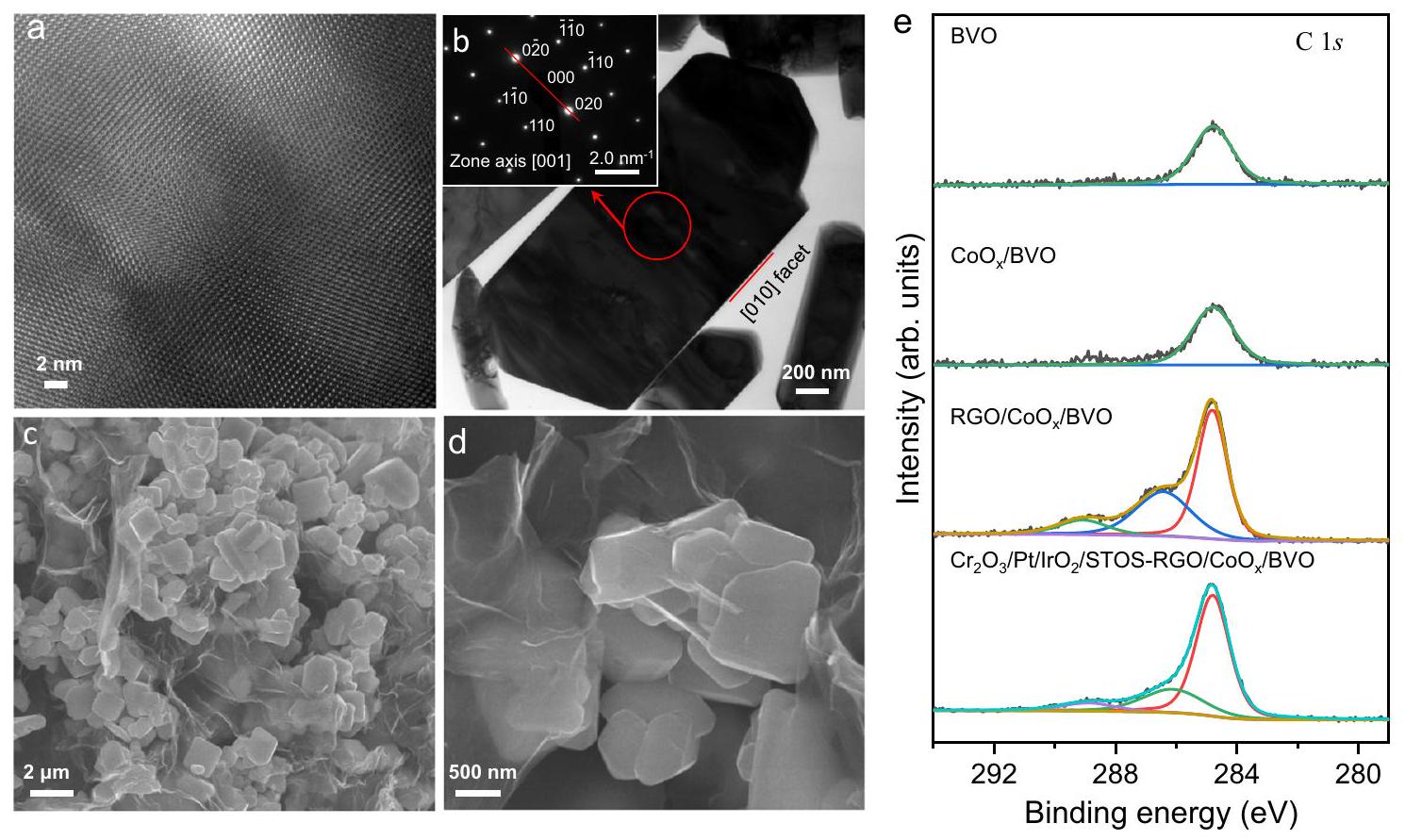
الشكل 1 | توصيف STOS. أ صورة SEM لعينة STOS.حواف الشبكة الناتجة عن STOS كما تم الحصول عليها باستخدام HR-TEM. ج صورة TEM لعينة STOS ونمط SAED المقابل. د صورة TEM لـ
الشكل 2 | توصيف BVO. أ الحواف الشبكية المستخرجة من BVO باستخدام HR-TEM.صورة TEM لعينة BVO ونمط SAED المقابل. ج، د صور SEM لـ RGO/عينة. قمم C1s XPS لكل عينة.
تم تحديد أحجام الجسيمات لتكون أقل من 1 نانومتر في الحجم بينما كانت جسيمات البلاتين تقريبًافي الحجم ويبدو أنه مغطى بـ (الشكل 1g). في الأعمال السابقة، وُجد أن STOS المُعد باستخدام تدفق CsCl يحتوي على و كشوائب. بالإضافة إلى ذلك، كانت الجسيمات الشبيهة بالصفائح من STOS التي تم إنتاجها في الأبحاث السابقة أرق من تلك الموجودة في الدراسة الحالية وظهرت بأشكال غير منتظمة، مما يدل على درجة أقل من البلورية (الشكل التكميلي 4). كما أظهر المادة السابقة استقرارًا كيميائيًا ضعيفًا، كما يتضح من رائحة قوية لـخلال المعالجة الحمضية المسبقة قبل التعديلات السطحية. أظهر تحليل XPS أن قمم Sm وتي تم تحريكها قليلاً إلى طاقة ربط أعلى وأدنى، على التوالي، مقارنة بتلك الموجودة في عينة STOS المحضرة بـ التدفق (الشكل التوضيحي التكميلي 5a، b). بالإضافة إلى ذلك، زادت شدة الذروة للأنواع الماصة للأكسجين بشكل كبير (الشكل التوضيحي التكميلي 5c). هناك نوعان إضافيان من S تمت ملاحظة القمم الموجودة عند 231.4 و 227.5 إلكترون فولت. يمكن أن تُنسب الأولى إلى تكوينبينما تم تخصيص الأخير للممتصكرائحة قوية منتم ملاحظته خلال المعالجة اللاحقة الحمضية (الشكل التوضيحي 5d). لذلك، كانت حالة سطح STOS-CsCl مختلفة بشكل ملحوظ عن STOS المُعد باستخدامالانصهار. تم ملاحظة العديد من الانزياحات على سطح (001) من STOS-CsCl وأكدت تحليلات TEM عالية الدقة وجود عيوب داخل البلورة (الشكل التوضيحي التكميلي 6). أشارت هذه النتائج إلى أن STOS المُعد باستخدام انصهار CsCl كان له بلورية ضعيفة. علاوة على ذلك، وُجد أن STOS يمكن الحصول عليه كمنتج رئيسي باستخدامأو فقط باستخدام فلز LiCl. في الحالة الأولى، تكون الشوائب منتمت ملاحظته أثناءتم العثور عليها في الأخيرة (الشكل التوضيحي 7). على عكس تدفق CsCl، لم يتم العثور على فرق واضح من خلال تحليل XPS (الشكل التوضيحي 8)، مما يشير إلى أن حالة سطح STOS لم تتغير بغض النظر عن أنواع مواد التدفق. ومع ذلك، فإن STOS- على شكل ورقةكانت الجسيمات أكبر وأكثر عدم انتظام، تشكل تكتلات، مقارنةً بـ STOS المحضرة بـخليط (الشكل التوضيحي 9أ). بالإضافة إلى ذلك، شوائب منتمت ملاحظة الجسيمات أيضًا بواسطة المجهر الإلكتروني الماسح. تم العثور على نتائج مماثلة في حالة STOS-LiCl (الشكل التكميلي 9b). نقاط الانصهار الأعلى لـ و من ذلك منخليط يوتيكتكقد تفسر انخفاض البلورية والنشاط الضوئي التحفيزي.
تم تقديم نمط XRD المستخرج من BVO في الشكل التكميلية 1b وهو متوافق مع البيانات التي تم الإبلاغ عنها سابقًا في الأدبيات.تم التأكيد على أن هذه المادة ذات بلورات عالية من خلال التحليلات باستخدام HR-TEM و SAED (الشكل 2 أ، ب). بعد ترسيب الضوء لـتم الكشف عن إشارة XPS ضعيفة لـ Co على BVO جنبًا إلى جنب مع قمم Bi و V و O (الشكل التوضيحي 10).. بعد تقليل أكسيد الجرافين بواسطة الضوء على تمت ملاحظة أسطح BVO وأوراق RGO المتجعدة بواسطة كل من SEM وTEM (الشكل 2c، d والشكل التكميلي 11).طيف XPS المكتسب من RGO الناتجعرضت BVO قممًا مركزة عندو 289.1 إلكترون فولت المنسوبة إلى و روابط RGO، على التوالي (الشكل 2e).
أداءات التحفيز الضوئي
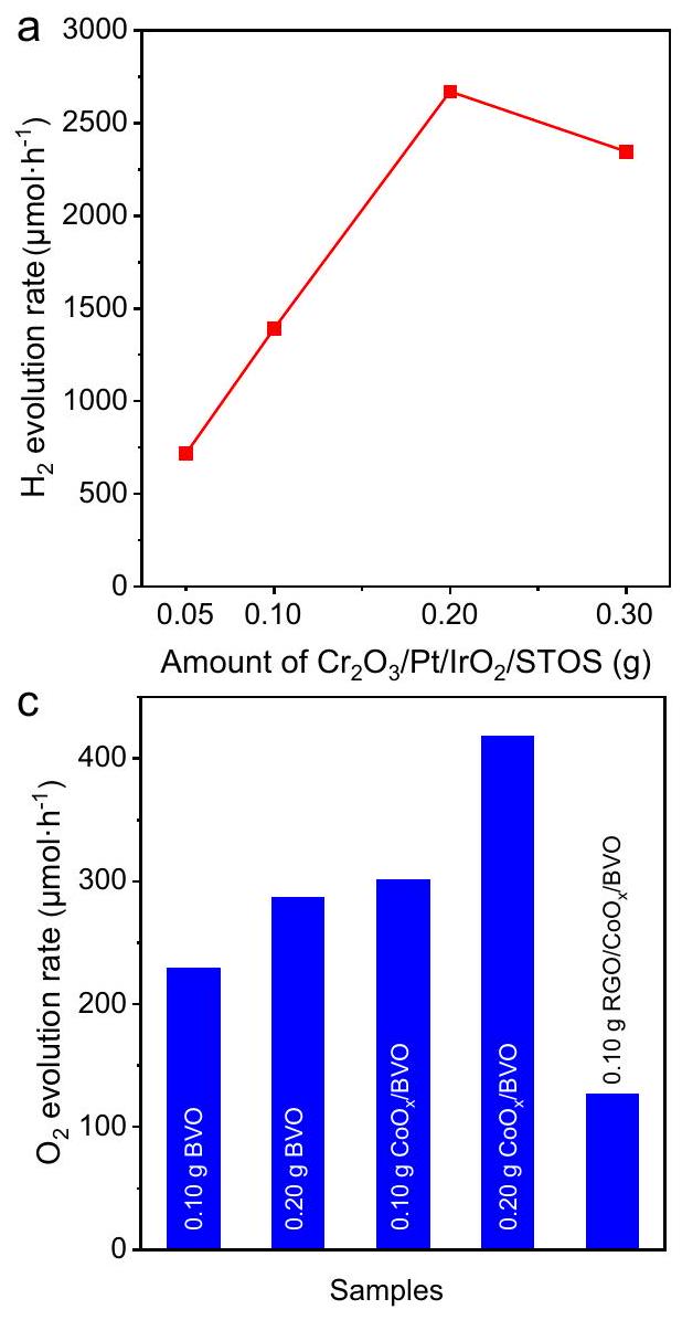
تم إجراء تفاعلات نصفية لتطور الهيدروجين والأكسجين باستخدام التحفيز الضوئي لتقييم أداء HEP و OEP. في هذه التجارب، لم يكن هناك تقريبًا أيتم تطويره من محلول مائي من الميثانول باستخدام STOS العاري، أو بسبب نقص المواقع النشطة.تمت ملاحظة التطور عند استخداممحفز STOS المحمّل، وتم تحسينه بشكل كبير من خلال تعديل إضافي مع (الشكل التوضيحي 12أ). الكمية المثلى للتحميل من ، و تم العثور عليها بنسبة 0.5 وزن و ، على التوالي (الشكل التكميلي 12ب-د). الـمعدل التطور لـكما وُجد أنه يزداد مع زيادة كتلة المحفز الضوئي المستخدم، ليصل إلى الحد الأقصى منخلال الساعة الأولى من العملية في حالة استخدام 0.2 جرام من المحفز الضوئي بالتزامن مع ظروف التفاعل الحالية (الشكل 3أ). إن زيادة تركيز مسحوق المحفز الضوئي ستعيق الضوء الساقط بسبب التشتت في الجزء العلوي من التعليق، مما سيقلل من عدد الفوتونات الممتصة بواسطة المحفز الضوئي وبالتالي يقلل منأداء التطور عندما كانت كمية المحفز الضوئي أكثر من 0.2 جرام. كانت رسم بياني لقيمة AQY كدالة لطول موجة الإشعاع تتطابق بشكل وثيق مع ملف امتصاص الضوء لـ STOS (الشكل 3ب). كانت قيمة AQY عند 420 نانومتر هيوكان ذلك 36 مرة من ذلك
الشكل 3 | التحفيز الضوئي و أنشطة التطور. أ،معدلات التطور علىفي الميثانول المائي كدالة لكتلة المحفز و b القيم المقابلة لـ AQY لـفي مختلف
الأطوال الموجية مع بيانات DRS.معدلات التطور على، و في الماءحلول وقيم AQY المقابلة لـعند أطوال موجية مختلفة مع بيانات DRS. تم الإبلاغ عنه سابقًا لـ STOS المحملة بالبلاتين وأظهر أيضًا قدرًا كبيرًا منقدرة التطور لكنها لم تكن فعالة كمافي هذا الصدد، مشيرًا إلى تحميل البضائع المشتركة لـمع ترقية Ptالجيل. يجب أيضًا ملاحظة أنه لا يوجدتم الحصول على نشاط التطور عند استخدام STOS المحضر باستخدام تدفق CsCl بعد نفس التعديلات السطحية، نتيجة لانخفاض البلورية وضعف استقرار هذه المادة. ثابتتمت ملاحظة الإنتاج تحت نفس ظروف التفاعل في حالة STOS- و STOS-LiCl بأداء مشابه، لكن كانت معدلات التطور أقل بكثير مقارنةً بـ STOS المعدة بواسطةخليط يوتيكتك بسبب جودة البلورات الضعيفة (الشكل التكميلي 12e).
في تجارب OEP، الأوليمعدل التطور كانبكمية 0.2 جرام من BVO العاري في وجودكعامل تضحية. بعد ترسيب الضوء لـ، ارتفع هذا المعدل إلى (الشكل 3ج). قيم AQY لـ تم تحديد التركيبة عند 420 و460 و500 نانومتر على أنها و ، على التوالي (الشكل 3d). من الجدير بالذكر أن ترسيب RGO بالضوء علىخفضت BVOمعدل التطور على الرغم من أن هذا التعديل كان ضروريًا لبناء نظام OWS فعال بنمط Z.
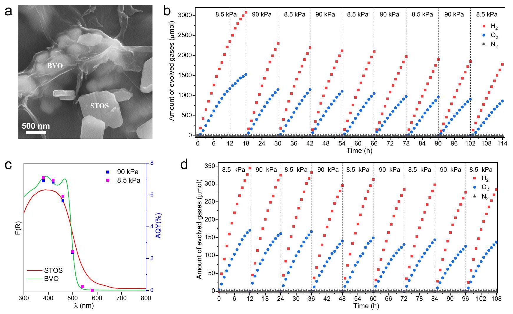
لضمان تشكيل نظام تقسيم الماء بنمط Z، تم تحديد الحد الأدنى من نطاق التوصيل (CBM) لـ STOS من خلال رسم موت-شوتكي، وكان يقع حوالي -0.6 فولت مقابل NHE (الشكل التكميلي 13a). وفقًا لفجوة الطاقة البالغة 1.9 إلكترون فولت التي تم الحصول عليها بواسطة طيف الانعكاس المنتشر للأشعة فوق البنفسجية والمرئية (DRS)، كان الحد الأقصى من نطاق التكافؤ (VBM) يقع حوالي 1.3 فولت مقابل NHE. بالاقتران مع موضع النطاق المبلغ عنه لـ، وُجد أن محاذاة النطاقات تسمح بنقل الشحنة بطريقة مخطط Z (الشكل التكميلي 13b). وبالتالي، تم إنتاج نظام OWS بطريقة مخطط Z استنادًا إلى HEP و OEP المُعدّين كما هو موضح أعلاه. في تفاعل نموذجي، 0.05 جرام منو 0.1 جرام من RGO/تم تعليقها في 150 مل من الماء النقي مع التحريك المستمر. وُجد أن نشاط هذا النظام يتحسن مع مرور الوقت خلال الساعات الاثني عشر الأولى (الشكل التكميلي 14). تشير هذه النتيجة إلى أن HEP و OEP المحملة بـ RGO خضعت لتفاعل ضوئي لتشكيل روابط كيميائية مشابهة لتلك التي تربط RGO و BVO. أظهرت صور SEM أن RGO غطت تدريجياً STOS و الجسيمات خلال فترة التحفيز هذه، مما يثبت وجود علاقة بين HEP و OEP (الشكل 4a والشكل التكميلي 15). من صور رسم EDX، يمكن تحديد STOS و BVO من خلال توزيع عناصر Sm و Bi، على التوالي (الشكل التكميلي 16). بالإضافة إلى ذلك، من أجل ملاحظة صفائح RGO بوضوح، تم استخدام كاشف إلكتروني ثانوي للتصوير. عند استخدام كاشف إلكترونات مرتدة للتصوير، من الممكن تمييز جسيمات STOS و BVO من خلال تباين التدرج الرمادي (الشكل التكميلي 17). وذلك لأن الإشارة للإلكترونات المرتدة تصبح أقوى مع زيادة العدد الذري للعناصر في المركب. العدد الذري لـ Bi أكبر من Sm وبالتالي تظهر جسيمات BVO أكثر سطوعًا من جسيمات STOS. بعد فترة التحفيز، تم إخلاء نظام التفاعل وتم إدخال الأرجون مرة أخرى إلى ضغط محدد. الحد الأقصى و معدلات التطور في المرحلة الأولية من هذه العملية تحت الضوء المرئي كانت 240 وعلى التوالي. قيمة AQY تساويتم تحقيقه استجابةً لـ 420 نانومتر أحادي اللون
الشكل 4 | تفاعل OWS الضوئي المحفز لنظام Z-scheme. أ صورة SEM لـبعد فترة التعريف.تطور الغازات من نظام Z-scheme مع مرور الوقت عند ضغوط خلفية مختلفة من الأرجون استجابةً لـقيم AQY الضوئية المستمدة من نظام Z-scheme تحت 8.5 و 90 كيلو باسكال من الأرجون عند أطوال موجية مختلفة مع بيانات DRS لنظام STOS و BVO. د تطور الغازات من نظام Z-scheme مع مرور الوقت عند ضغوط خلفية مختلفة من الأرجون استجابة للإشعاع باستخدام جهاز محاكاة شمسية AM1.5 G. الضوء (الشكل 4ج)، الذي كان أعلى بمقدار 7 مرات من ذلك لنظام يتكون من و . بالإضافة إلى ذلك، تم تعزيز النشاط من خلال زيادة تحميل GO من 0.3 إلى فيما يتعلق بكتلة BVO. لم يوفر زيادة كمية GO أي مكاسب إضافية في الأداء (الشكل التكميلي 18a). وفقًا للتحليل العنصري، زادت كمية الكربون المحملة تدريجياً مع زيادة كمية GO المضافة (الجدول التكميلي 1). لم يتم ترسيب كل GO عند الكمية المضافة الأعلى وتمت إزالة GO الزائد ببساطة خلال إجراء الطرد المركزي. في غياب GO على على السطح، أصبحت نشاط نظام Z-scheme أقل بمقدارين من حيث الحجم بسبب انتقال الحوامل الناتجة عن الضوء بين و أصبحت الجسيمات غير فعالة للغاية. ومن الجدير بالذكر أن نشاط نظام OWS الحالي من نوع Z-scheme كان يعتمد بشكل كبير على نوع GO المستخدم، متراوحًا من 7 إلى (استنادًا إلى معدل التطور) حيث تم تغيير المادة، كما هو موضح في الشكل التكميلي 18b. وفقًا لتحليل SEM، كانت النشاط في أقصى حد في الحالة التي كانت فيها RGO موجودة كأوراق كبيرة، مما من المحتمل أنه ساعد على الاتصال الوثيق مع OEP و HEP (الشكل التكميلي 18c-e).
طيف الامتصاص العابر
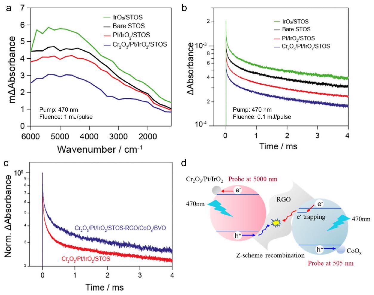
تمت دراسة نظام Z-scheme أيضًا باستخدام مطيافية الامتصاص العابر (TAS) لمراقبة نقل الشحنة من المحفزات الضوئية إلى المحفزات المساعدة ومن OEP إلى HEP.. أظهرت إشارات TAS المستمدة من STOS العاري في أوقات تأخير مختلفة امتصاصًا واسعًا على مدى الطول الموجي بالكامل (الشكل 5a والشكل التكميلي 19). عاشت حاملات الشحنة في هذه المادة لأكثر من 4 مللي ثانية، مما يشير إلى أن حاملات الشحنة من المحتمل أن تكون قادرة على الهجرة إلى سطح المحفز (الشكل 5b). تم فحص STOS المحمّل بـ IrO2 أيضًا وولد طيفًا مشابهًا لتلك الخاصة بالعاري. عينة، مما يوحي بوجود حاملات ضوئية في STOS المثارة. أظهر ملف الانحلال الزمني للإلكترونات المراقب عند 5000 نانومتر زيادة في شدة الإشارة بعد التحميل. وبالتالي، من المحتمل أن الثقوب الناتجة عن الضوء في STOS تم التقاطها بواسطة مما يؤدي إلى زيادة عدد الإلكترونات في المادة. على النقيض، تم تقليل شدة TAS بشكل كبير بعد الإيداع المتسلسل للبلاتين و، مما يشير إلى تقليل عدد الإلكترونات في STOS وبالتالي زيادة التقاط الإلكترونات بواسطة المساعد المساعد. هذه النتائج تتماشى مع التحسن الكبير في التحفيز الضوئيالجيل الذي أظهرته STOS بعد التعديلات السطحية (الشكل التكميلي 12a). في تحليل BVO، تم مراقبة الثقوب المحصورة على السطح الناتجة عن الضوء فياستنادًا إلى الدراسات المبلغ عنها سابقًا حول هذه المركب. تحميل كعامل مساعد مفتوح المصدر على سطح BVO، وُجد أنه يقلل من شدة إشارة TAS عند 505 نانومتر ويُسرع من تدهور الثقوب المثارة ضوئيًا في BVO، مما يشير إلى تعزيز التقاط الثقوب بواسطة العامل المساعد. تم تسريع تدهور الإشارة بشكل أكبر بعد تحميل العامل المساعد مع RGO، مما يوحي بأن الثقوب والإلكترونات تم التقاطها بواسطة RGO بحيث تم تعزيز إعادة التركيب (الشكل التكميلي 20). كانت هذه النتيجة متوافقة مع الانخفاضنشاط التطور الملحوظ بعد ترسيب RGO بالضوء على.
في التجارب التي تقيم نظام Z-scheme، تم استخدام مضخة بطول موجي 470 نانومتر لتحفيز كل من HEP و OEP. تم عزو إشارة TAS الملاحظة عند 5000 نانومتر على مقياس الزمن من الميكروثانية إلى المللي ثانية إلى الإلكترونات في STOS لأن شدة الإشارة كانت أضعف بكثير عندما تم إشعاع BVO بمفرده (الشكل التكميلي 21). كانت فترة تلاشي الإلكترونات المثارة ضوئيًا في نظام Z-scheme أطول مقارنة بتلك في (الشكل 5ج). يُعزى هذا الاختلاف إلى إعادة تركيب الإلكترونات من BVO مع الثقوب من STOS، مما يعني أن إعادة تركيب الإلكترونات والثقوب في STOS تم تقليلها. سمح هذا التأثير لـ
الشكل 5 | بيانات TAS. أ طيف الامتصاص العابر في منتصف الأشعة تحت الحمراء وديناميكية التحلل عند 5000 نانومتر المستمدة من STOS العاري و STOS المحمّل بـ و ديناميكية تحلل الحوامل في و
رسم بياني يلخص آلية نقل الشحنة بين HEP و OEP في نظام Z-scheme. التقاط الفعال للإلكترونات والفجوات بواسطة المحفزات المساعدة لتطور الهيدروجين والأكسجين، على التوالي، كما هو موضح في المخطط المقدم في الشكل 5d. بعد التحفيز الضوئي الانتقائي لـ HEP باستخدام مضخة 560 نانومتر، تلاشت الإلكترونات المثارة ضوئيًا بشكل أسرع في نظام Z-scheme مقارنة بتلك في (الشكل التوضيحي 22a) نتيجة لغياب الإلكترونات الناتجة عن الضوء من BVO القادرة على إعادة التركيب مع الثقوب في STOS. وبالتالي، تم تسريع إعادة تركيب الإلكترونات والثقوب الناتجة عن الضوء في STOS الكتلي أو على RGO (الشكل التوضيحي 22b). تؤكد هذه النتائج آلية تقسيم الماء بنظام Z التي تتم بناءً على التحفيز الضوئي لكل من HEP و OEP. لدعم تعزيز نقل الشحنة بواسطة RGO في نظام Z، تم قياس TAS بعد الإشعاع في حالة الاستقرار في غياب ووجود بخار الماء في جو نيتروجيني لنظام Z مع وبدون RGO (الشكل التوضيحي 23). لاحظ أن الإلكترونات المتراكمة يمكن أن تشارك في عملية تقليل الماء في وجود بخار الماء. في غياب RGO، كان تدهور الإلكترونات بالكاد يتسارع من خلال إدخال بخار الماء، مما يشير إلى كفاءة منخفضة في تفاعل تقليل الماء بواسطة الإلكترونات المثارة ضوئيًا. من المثير للاهتمام، عندما تم دمج RGO في نظام Z، تسارع تدهور الإلكترونات بشكل كبير عند التعرض لبخار الماء. وهذا يعني أن تفاعل الإلكترونات المتراكمة لتقليل الماء قد تم تعزيزه بشكل كبير بواسطة RGO مما يعزز تشكيل نظام Z. أظهرت هذه النتائج أن ارتباط HEP و OEP مع RGO يمكن أن يعزز بشكل كبير نقل الشحنة بين HEP و OEP.
عوامل تعزز النشاط الضوئي التحفيزي
تم إجراء تجارب ضابطة من أجل التحقيق بشكل أعمق في الآلية المسؤولة عن النشاط المعزز لنظام المحفز الحالي. في هذه التجارب، تم استبدال الوسيط الإلكتروني في الحالة الصلبة RGO إما بـأوتعمل كزوج أيوني، وكلاهما قد تم استخدامه بشكل شائع في الأعمال السابقة. استخدام ، فقطتمت ملاحظة تطور خلال تفاعل ضوئي لمدة 12 ساعة، مما يشير إلى أن تفاعل أكسدة الماء لم يتقدم في هذا النظام (الشكل التوضيحي 24a). على الرغم من أن تفاعل OWS تقدم معزوج أيوني، كانت النشاطية تقريبًا نصف تلك التي تم الحصول عليها باستخدام RGO كوسيط إلكتروني. بالإضافة إلى ذلك، وُجد أن معدل تطور الغاز ينخفض مع زيادة وقت التفاعل الضوئي (الشكل التوضيحي 24b). يُعزى هذا الظاهرة إلى الرقم الهيدروجيني المنخفض 2.3 المستخدم بالتزامن معزوج أيوني، والذي كان ضارًا باستقرار المساعدات المساعدة و. تشير هذه النتائج إلى أن RGO كان وسيلة أكثر كفاءة واستقرارًا لتعزيز نقل الإلكترونات من OEP إلى HEP. في تجارب إضافية، تم تحميل STOS بـ أو تم استخدامه كـ HEP لتقييم تأثير طرق تعديل السطح على الأداء. لم تتقدم تفاعل OWS بنظام Z عندما كان Pt/IrOتم استخدام STOS كـ HEP، والذي يمكن أن يُعزى إلى التقدم المتزايد في التفاعل العكسي في غيابمهم و تم الحصول على معدلات التطور مع النسبة المولية الستيوكيومترية المتوقعة 2:1 في التجارب باستخدام كـ HEP، على الرغم من أن النشاط كان أقل من ذلك الذي لوحظ مع (الشكل التوضيحي 25أ). من الواضح أن البلاتين وكان مطلوبًا إنشاء مواقع التطور وتثبيط التفاعل العكسي، على التوالي، بينما دور تم استكشافه بواسطةتطور STOS مع تعديلات سطحية مختلفة. نشاط محسّن بشكل ملحوظ لـتمت ملاحظة التطور عندماتم تحميله (الشكل التوضيحي 25ب). تم تعزيز النشاط في كل من و تفاعلات نصف التطور تشير إلى أنيمكن أن تلتقط الثقوب الناتجة عن الضوء وبالتالي تعزز فصل الشحنات، مما يؤدي إلى تحسين أداء HEP في عملية تحليل الماء بشكل عام. ومع ذلك، فينصف تفاعل التطورلم يكن محفزًا مساعدًا فعالًا في أكسدة المادة المتضحية. لذلك، فإنلم يكن معدل التطور محسناً بشكل ملحوظ بعد تحميل الكمية المزدوجة منبشكل عام، كانت الاتجاهات الملحوظة في نشاط تفاعل OWS في مخطط Z عند استخدام عينات HEP ذات تعديلات سطحية مختلفة هي نفسها التي لوحظت في المقابلنصف التطور معدلات التفاعل. لذلك، كانت النشاط العالي لـ HEP وعمل RGO كوسيط إلكتروني فعال في الحالة الصلبة مع قمع التفاعل العكسي هي العوامل الرئيسية التي تفسر الأداء الأعلى لـ OWS.
تمت دراسة تأثير الضغط الخلفي على نشاط تحليل الماء بشكل إضافي. ومن المثير للاهتمام أن نظام Z-المخطط الحالي أظهر أنشطة تحليل ماء وقيم AQY مماثلة عند ضغوط خلفية من الأرجون تبلغ 8.5 و90 كيلو باسكال (الشكل 4b، c). لذلك، كان للضغط الخلفي تأثير ضئيل على هذا النظام، مما يعد ميزة لتطبيق نظام Z-المخطط الذي تم إنشاؤه تحت ظروف التشغيل العملية. لوحظ أن النشاط بدأ يتناقص تدريجياً مع مرور الوقت (بواسطةبعد 114 ساعة) بغض النظر عن الضغط، على الرغم من و تم تطويرها باستمرار عند النسبة المولية المتوقعة 2:1. بعد تفاعل ضوئي استمر لمدة 114 ساعة تحت الضوء المرئي، تم جمع العينة عن طريق الترشيح وتجفيفها استعدادًا للتوصيف. تم الحصول على أنماط XRD من كل من مراحل STOS و BVO (الشكل التكميلي 26). وُجد أن قمم XPS الناتجة عن العناصر المكونة كانت مشابهة قبل وبعد التفاعل، مما يؤكد استقرار المحفزات الضوئية والمحفزات المساعدة (الشكل التكميلي 27). ومع ذلك، تم التأكيد بصريًا على التصاق مسحوق المحفز الضوئي بجدار المفاعل بعد التفاعل الضوئي لجولة واحدة (12 ساعة) (الشكل التكميلي 28). تم جمع مسحوق المحفز الضوئي في المحلول بعناية عن طريق الترشيح، تلاه التجفيف في فرن الفراغ. تم تكرار الإجراء ثلاث مرات وكان متوسط كمية المحفز الضوئي المتبقية 146.8 ملغ. وهذا يعني أنه في جولة واحدة من التفاعل الضوئي لمدة 12 ساعة، سيلتصق 3.2 ملغ من المحفز الضوئي بجدار المفاعل. بعد كل جولة، سيلتصق مقدار مشابه من مسحوق المحفز الضوئي بجدار المفاعل. خلال 8 جولات لمدة إجمالية تبلغ 114 ساعة، ستكون كمية المسحوق المفقود حوالي 24 ملغ. لذلك، تم عزو الانخفاض الواضح في النشاط بشكل أساسي إلى التصاق مسحوق المحفز الضوئي بجدار المفاعل بدلاً من التدهور (الضوئي) الكيميائي لمكونات نظام Z-scheme. تم تحديد قيمة STH لنظام OWS من نوع Z-scheme لتكون تحت ضوء الشمس المحاكى (AM 1.5 G) وكان بذلك أعلى بـ 73 مرة من ذلك المبلغ عنه لنظام Z-scheme السابق الذي يتكون من STOS تم تصنيعه باستخدام تدفق كـ HEP وكزوج وسيط الإلكترونمرة أخرى، كان لضغط الخلفية تأثير ضئيل على الأداء وتم تحقيق STH بنسبة 0.21% تحت الأرجون عند ضغط خلفية قدره 90 كيلو باسكال (الشكل 4d).
تصنيع أوراق Z-scheme OWS
على الرغم من أن مفهوم نظام التعليق هو أبسط نهج لتعزيز OWS على نطاق المختبر، إلا أن الألواح القابلة لتفكيك الماء التي تحتوي على محفزات ضوئية ثابتة هي أكثر ملاءمة لبناء مفاعلات على نطاق واسع.. لذلك، في العمل الحالي، تم تثبيت نظام Z-scheme على ركيزة لتصنيع أوراق محفز ضوئي جزيئي لتفاعل OWS. من الجدير بالذكر أن هذه الأوراق المحفزة الضوئية أظهرت نشاطًا Comparable لنظام التعليق تحت ظروف تفاعل مماثلة (الشكل التكميلي 29a). علاوة على ذلك، حافظت هذه الأوراق على لنشاطهم الأصلي تحت ضغط خلفية قدره 90 كيلو باسكال مقارنةً بذلك تحت ضغط خلفية قدره 8.5 كيلو باسكال، واحتفظوا أيضًامن أدائها الأصلي بعد تفاعل ضوئي لمدة 108 ساعات (الشكل التكميلي 29b). على الرغم من أن النشاط كان أقل من أفضل أداء أظهره نظام التعليق، إلا أن هذه النتائج تدعم على الأقل جدوى توسيع نظام Z-scheme الحالي.
عوامل تحد من الأداء
في الوقت الحالي، قيمة STH لنظام Z-scheme أقل بكثير من تلك المطلوبة للاستخدام العملي.الإنتاج من خلال التحليل الضوئي للماء، وبالتالي هناك حاجة إلى تحسينات دراماتيكية في الأداءتتطابق التغيرات في بيانات AQY لتفاعل OWS (الشكل 4c) بشكل وثيق مع خصائص امتصاص الضوء لـ BVO بدلاً من STOS. لذلك، يُعتبر أن استخدام ضوء الشمس في مخطط Z الحالي لتفكيك الماء النظام محدود بواسطة OEP، الذي لديه فجوة نطاق واسعة نسبيًايمكن أن يكون دمج OEP قادر على امتصاص الضوء بطول موجة أطول نهجًا فعالًا لتحسين الأداء. بالإضافة إلى ذلك،معدل التطور خلال تفاعل OWS بنظام Z كان متأثراً بشكل طفيف بزيادة الضغط الخلفي بناءً على التقديمبينمامعدل التطور انخفض بشكل ملحوظ عند إضافة (الأشكال التكميلية 30a، b). تشير هذه النتائج إلى حدوث تفاعل أكسدة الهيدروجين () مع الزيادات في الضغط الجزئي داخل بيئة التفاعل، مما يؤدي إلى إعادة تركيب الشحنات من خلال دورات تقليل الماء وأكسدة الهيدروجين تحت الإضاءة (الشكل التكميلي 30c). في الواقع، تم ملاحظة حدوث أكسدة الهيدروجين أيضًا بالتزامن مع تفاعل تطور الهيدروجين من محاليل الميثانول المائية. بافتراض وجود تفاعل عكسي يعتمد على الضغط الجزئي للهيدروجين من الدرجة الأولى، كان من الممكن ملاءمة رسم بياني لتطور الهيدروجين مع مرور الوقت (الشكل التكميلي 30d). زيادة في كمية كما زادت STOS من كمية المحفز المساعد من البلاتين الذي سرع تفاعل أكسدة الهيدروجين، الذي يتنافس معتفاعل التطور الأمامي. كانت هذه سببًا آخر يفسر الانخفاضمعدل التطور عندما تجاوزت كمية المحفز الضوئي 0.2 جرام (الشكل 3أ). علاوة على ذلك، كميات الغازية و تم العثور عليها تتناقص تدريجياً في غياب الضوء، مما يوفر دليلاً إضافياً على حدوث التفاعل العكسي في نظام Z-scheme (الشكل التكميلي 31a). من الواضح أن التفاعل العكسي حدث بشكل أسرع على STOS في غياب التغطية ولكن لم تحدث في التجارب التي تستخدم أو الأنظمة (الأشكال التكميلية 31ب-هـ). من الواضح أن مكون البلاتين من المساعد المساعد عزز التفاعل العكسي. على الرغم من أن الترسيب الضوئي لـعلى النقطة أبطأت معدلات و الاستهلاك، لا تزال التفاعل العكسي يحدث لأن و تمكنوا من اختراق غير الكاملالقشور للتواصل مع المحفز المساعد Pt (الأشكال التكميلية 31f و g). تم تثبيط التفاعل العكسي بشكل أكبر من خلال زيادة كمية المواد المودعة بالضوءما وراء (الشكل التوضيحي 32a). ومع ذلك، في نفس الوقت، كان أداء التطور يتناقص تدريجياً مع زيادةتحميل الكمية (الشكل التكميلي 32ب). في الوقت نفسه، تم تقليل أداء عملية التحليل الكهربائي للماء بشكل عام (الشكل التكميلي 32ج). لذلك، تم ترسيب الضوء لـكان هناك مقدار مثالي لتحقيق التوازن بين التفاعل الأمامي والتفاعل العكسي. بالإضافة إلى ذلك، انخفض أداء نظام Z-scheme OWS مع زيادة كميات HEP و OEP في نظام Z-scheme (الشكل التوضيحي 33). كانت هذه النتيجة متناقضة مع سلوك التفاعلات النصفية المقابلة، التي كانت لها و زادت معدلات التطور مع زيادة كميات المحفزات الضوئية ضمن نطاقات معينة محددة (الشكل 3أ، ج). يمكن أن تُعزى هذه الظواهر إلى رد الفعل العكسي المعزز الذي يحدث في نظام Z-scheme OWS مع زيادة كمية HEP. وبناءً عليه، فإن مزيدًا من كبح رد الفعل العكسي على HEP سيكون وسيلة أخرى لتعزيز الأداء العام لنظام Z-scheme. في حالة نظام الورقة، زادت نسبة جزيئات المحفز الضوئي المظللة بواسطة جزيئات أخرى في الطبقة الجزيئية. لم تعزز هذه النسبة المظللة من المحفز الضوئي تفاعل Z-scheme OWS ولكنها عززت رد الفعل العكسي (الذي تسبب فيه مكون البلاتين في المساعد المساعد) وبالتالي قللت من النشاط العام. لذلك، فإن تحسين عملية تصنيع الورقة هو جانب أساسي لتحسين الأداء.
باختصار، تم تحضير عينة STOS عالية الأداء تتميز بدرجة عالية من البلورية وأعمار حاملات طويلة بواسطة طريقة مساعدة بالفلux. كانت AQY لـتم تحقيقه عند 420 نانومتر فيما يتعلق بـتفاعل نصف التطور بعد تعديل السطح بـ ، و نظام مخطط Z يعتمد على هذه المادة كـ HEP، وBVO كـ OEP، وRGO كوسيط إلكتروني في الحالة الصلبة أظهر STH قدرهخلال رد فعل OWS. كانت هذه القيمة أعلى بـ 73 مرة من تلك التي تم الحصول عليها سابقًا من نظام Z-scheme تم بناؤه باستخدام STOS و، بسبب النشاط المعزز لـ HEP و OEP الحاليين والانتقال الفعال للإلكترونات من OEP إلى HEP عبر RGO. كانت نشاط تفكيك الماء في هذا النظام تقريبًا مستقلة عن ضغط غاز الأرجون لأن التفاعلات العكسية تم قمعها إلى حد كبير من خلال تعديل السطح بـتم تصنيع نظام OWS من نوع اللوحة النموذجية مناسب للتطبيقات واسعة النطاق استنادًا إلى هذا النظام من نوع Z وأظهر نشاطًا Comparable لنظام التعليق. تُظهر هذه الدراسة أن تعزيز النشاط الجوهري لـ HEP يمكن أن يعزز بشكل كبير الأداء العام لنظام OWS من نوع Z. تم تأكيد أهمية نقل الشحنة بين HEP و OEP من خلال تحليل TAS وتم دراسة التفاعل العكسي بالتفصيل، مما سيوجه التطوير المستقبلي لنظام Z. تشير هذه الدراسة أيضًا إلى أنه، بناءً على تحسين نشاط OEP معًا مع تثبيط التفاعل العكسي وتقليل تكلفة المفاعل الضوئي والمحفزات المساعدة، يمكن تحقيق نظام OWS من نوع Z عالي الأداء يلبي متطلبات التطبيقات واسعة النطاق.
طرق
تحضير مسحوق STOS بطريقة الفلكس
تم تخليق مسحوق STOS من خلال دمج المواد الأولية. (0.489 جرام، واكو)، (0.215 جرام، مواد كيميائية عالية النقاء)، و (0.295 جرام، شركة رير ميتاليك المحدودة) بنسبة مولية 1:2:6 تليها الطحن في صندوق قفازات مملوء بـ. بعد ذلك، تم إضافة مسحوق الكبريت (مواد كيميائية عالية النقاء) إلى المواد الأولية لإنتاج بيئة غنية بالكبريت. بعد ذلك،تدفق (نسبة الكتلة، واكو) أُضيفت إلى الخليط فينسبة الكتلة بالنسبة لكتلة الخليط الأصلي، وتمت إعادة طحن الخليط بالكامل. ثم تم ختم المسحوق المحضر في أنبوب كوارتز تحت فراغ وتم تسخينه عند 973 كلفن لمدة 24 ساعة. بعد السماح له بالبرودة بشكل طبيعي إلى درجة حرارة الغرفة، تم توزيع المنتج في ماء منزوع الأيونات (DI) لذوبان LiCl/تم الحصول على مسحوق STOS الناتج عن الفلترة ثم تم تجفيفه في فرن مفرغ من الهواء. تم إزالة الكبريت الزائد من المنتج عن طريق تحميص STOS في الهواء عند 473 كلفن لمدة ساعة واحدة تليها الغسيل في، واكو) لمدة 15 دقيقة. أخيرًا، تم غسل المنتج المسحوق عدة مرات بماء منزوع الأيونات، وتم إزالته عن طريق الترشيح وتجفيفه في فرن مفرغ. كانت إجراءات تحضير STOS مع تدفقات مختلفة هي نفسها كما في التيار ولكن استبدل الخليط الإيتكتيني بـواكو” أو واكو) أو ، واكو)، حيث تم تسمية العينات التي تم الحصول عليها باسم STOS-CsCl، STOS-و STOS-LiCl، على التوالي. ما لم يُذكر خلاف ذلك، فإن مصطلح “STOS” يشير إلى العينة التي تم إعدادها بواسطةتدفق.
تعديل سطح STOS
تم تفريق كمية 0.2 جرام من مسحوق STOS فيتليها إضافة 0.5 مل من المحلول المائيحلشركة طوكيو للصناعات الكيميائية المحدودة) كافية لإعطاء تركيز إيربالنسبة لكمية STOS. تم نقل الخليط الناتج إلى قنينة زجاجية ثم تم تسخينه في مفاعل ميكروويف عند 423 كلفن لمدة 15 دقيقة.ثم تم توزيع الخليط في 15 مل من الإيثيلين جلايكول (واكو) ومحلول مائي من (كانتو) أُضيف بما يكفي ليعطي التركيز بالنسبة لكمية STOS. تم نقل المحلول إلى قنينة زجاجية وتم تسخينه في مفاعل ميكروويف عند 423 كلفن لمدة 15 دقيقة. بعد ذلك مباشرة، تم ترسيبها ضوئيًا علىيستخدم (Wako) كمادة سابقة في 150 مل من محلول ميثانول مائي. تم تنفيذ هذه الخطوة باستخدام إشعاع كامل الطيف بواسطة مصباح زينون بقوة 300 واط، مشابهة للظروف تم تطبيقه خلال التحفيز الضوئيتجارب التطور الموصوفة أدناه. بعد تفاعل ضوئي لمدة ساعة واحدة،تم جمعه عن طريق الترشيح وغسله عدة مرات بماء منزوع الأيونات.
تحضير مسحوق BVO بطريقة الهيدروحرارية
تم تحضير محلول سابق عن طريق إذابة 10.0 مللي مول من (1.170 جرام، واكو) و 10.0 مليمول من ، واكو) في محلول حمض النيتريك بتركيز 2.0 م (60 مل ، واكو) ، الذي تم ضبط درجة حموضته لتكون حوالي 0.5 عن طريق إضافة محلول الأمونيا ( تم تحريك المحلول الناتج لمدة ساعتين، وخلال هذه الفترة تشكل راسب أصفر باهت. تم نقل هذا المنتج إلى وعاء أوتوكلاف من الفولاذ المقاوم للصدأ مبطن بتفلون لمعالجة مائية حرارية عند 473 كلفن لمدة 24 ساعة. بعد التبريد الطبيعي، تم الحصول على مسحوق BVO عن طريق الترشيح والتجفيف في فرن مفرغ.
تحميل المساعد المساعد الكوبالت على BVO
تم تحميل محفز مساعد من الكوبالت على BVO باستخدام طريقة الترسيب الضوئي. في هذه العملية، تم توزيع 0.2 جرام من BVO في 150 مل من محلول عازل فوسفات بتركيز 50 مللي مولار (pH 6.0) يحتوي على (كانتو) بحيث تكون التركيز النهائي لـ Co بالنسبة لكمية BVO. ثم تم تعريض التعليق للإشعاع بواسطة ضوء الطيف الكامل الناتج عن مصباح Xe بقوة 300 واط لمدة ساعة واحدة، مشابهًا لعملية التحفيز الضوئي.إجراء التطور الموصوف أدناه. بعد الإزالة عن طريق الترشيح والغسل،تم الحصول على BVO.
ترسيب ضوئي لـ RGO
تم استخدام أربعة أنواع من أكسيد الجرافين المصنوع في المختبر (LM-GO) خلال تجارب التصوير الضوئي. يُشار إليها هنا باسم LM-GO-I و LM-GO-II و LM-GO-III و LM-GO-IV. تم تحضير LM-GO-I عن طريق إضافة الجرافيت (SP-1، Bay Carbon Inc.; 3.0 جرام) إلىتليها إضافة ببطءلإعطاء جرافيت:نسبة الكتلة 1:3 مع التحريك بسرعة 200 دورة في الدقيقة والتبريد إلى. تم الاحتفاظ بالمزيج بعد ذلك في لمدة ساعتين قبل التبريد بإضافةمع التحريك النشيط والتبريد لضمان عدم تجاوز درجة الحرارة. بعد ذلك، حل ( تمت الإضافة ببطء مع التحريك المستمر على مدى 30 دقيقة عند درجة حرارة الغرفة. أخيرًا، تم تنقية خليط التفاعل عن طريق الطرد المركزي.. تم استخدام نفس الإجراء لتحضير LM-GO-II ولكن، بعد الطرد المركزي وإعادة التعليق في الماء، تم ضبط تركيز GO في التعليق إلى بعد ذلك، تم معالجة المادة باستخدام طحن النفاث الرطب باستخدام فوهة بقطر 0.1 مم في. تم تحضير LM-GO-III بنفس الطريقة التي تم بها تحضير LM-GO-I ولكن تم أكسدة الجرافيت مرتين تحت نفس الظروف. في حالة LM-GO-IV، كانت إجراءات التخليق هي نفسها المستخدمة لتحضير LM-GO-II ولكن تم أكسدة الجرافيت مرتين تحت نفس الظروف. تم استخدام سبعة أنواع من أكسيد الجرافين التجاري: G-22L، G-21L، G-20-1، G-20L، G-17A، G-17S و G-19. في كل إجراء، تم تفريقه في 150 مل منمحلول مائي من الميثانول (واكو) بعد ذلك تم إضافة تشتت أكسيد الجرافين. ما لم يُذكر خلاف ذلك،LM-GO-I بالنسبة لكتلةتمت إضافته إلى محلول الميثانول المائي، الذي يحتوي علىتم تعريض الخليط بعد ذلك لإشعاع كامل الطيف من مصباح زينون بقوة 300 واط لمدة 3 ساعات، بعد ذلكتم عزلها بواسطة الطرد المركزي.
تحفيز ضوئي أو تطور
تم إجراء تجارب تطور الهيدروجين الضوئي المحفز في وعاء تفاعل زجاجي من نوع Pyrex مضاء من الأعلى متصل بنظام مغلق لتدوير الغاز. بعد ترسيب الضوء لـبالنسبة لكتلة STOS، كمية محددة من ( ، و 0.3 جرام) تم إعادة تشتته في 150 مل من محلول مائي من الميثانول. ظروف التفاعل الضوئي في التجارب التي استخدمت 0.2 جرام من STOS،، و كانت هي نفسها المستخدمة في التجارب معتم إجراء تطور الأكسجين الضوئي الحفاز عن طريق توزيع كمية محددة من العينات في 150 مل من محلول 50 مليمول. محلول مائي من (Wako). بعد إزالة الهواء تمامًا من النظام عن طريق التفريغ، تم ضبط الضغط الخلفي عن طريق إدخال غاز الأرجون إلى ضغط محدد مسبقًا. ما لم يُذكر خلاف ذلك، تم ضبط الضغط الخلفي على 8.5 كيلو باسكال لـ و نصف تفاعلات التطور. بعد اتباع هذه الخطوات، تم تعريض كل تعليق لأشعة مصباح زينون بقوة 300 واط مزود بفلتر قطع (L42، ) بينما تم الحفاظ على درجة حرارة نظام التفاعل عند 288 كلفن عن طريق تدوير الماء المبرد. الغازي أو تم تحليل الغاز المتطور خلال كل تفاعل باستخدام نظام متكامل للكشف عن الموصلية الحرارية – كروماتوغرافيا الغاز يتكون من كروماتوغراف الغاز GC-8A (شركة شيمادزو) مزود بـعمود غربال جزيئي، باستخدام الأرجون كغاز حامل.
مؤامراتتمت ملاءمة توليد الهيدروجين من خلال تفاعل تطور الهيدروجين مع مرور الوقت من خلال افتراض معدل التفاعل الأمامي ()، مما يعني أن تفاعل تطور الهيدروجين كان مستقلاً عن ضغط الهيدروجين الجزئي ( ). لذلك تم اعتبار هذه النسبة ثابتة ( المرتبطة بشدة الإثارة و AQY. معدل التفاعل العكسي (أي، تفاعل أكسدة الهيدروجين، .كان يُفترض أيضًا أن يكون متناسبًا مع ضغط الهيدروجين الجزئي، مع معامل تناسبي (أو ثابت معدل) منبشكل عام، تم حساب معدل تغير ضغط الهيدروجين الجزئي على أنهتم حل هذه المعادلة التفاضلية غير المتجانسة من الدرجة الأولى على النحو التالي
بناء نظام Z-scheme لتفاعل OWS
في تجربة نموذجية، تم إعدادها حديثًا و تم dispersing المساحيق في 150 مل من الماء النقي للغاية وتم تعريضها لأشعة مصباح زينون بقوة 300 واط مزود بفلتر قطع (L42، ) لمدة 12 ساعة .
تحضير أوراق المحفز الضوئي
بعد فترة التحفيز والتعافي عن طريق الترشيح، 0.02 جرام من المجففمسحوق و0.01 جرام من جزيئات السيليكا بحجم النانو (Nano Tek) تم تفريقها في 1 مل من الماء النقي للغاية وتم تعريضها للموجات فوق الصوتية لمدة 5 دقائق. بعد ذلك، تم صب التعليق الناتج علىركيزة زجاجية ثم تم تجفيفها على لوحة ساخنة عند 323 كلفن.
تفاعلات OWS باستخدام مخاليط وأوراق في نظام Z-المحفز الضوئي
بعد فترة التحفيز، تم إخلاء النظام وتم ضبط الضغط الخلفي ليكون حوالي 8.5 أو 90 كيلو باسكال عن طريق إدخال غاز الأرجون. تم إجراء تفاعل OWS بعد ذلك باستخدام إعداد مشابه لذلك المستخدم خلال الـتجارب التطور. تم تعريض النظام لأشعة مصباح زينون بقوة 300 واط مزود بفلتر قطع (L42، ). خصائص أداء نظام Z-scheme مع أو كانت الأزواج الأيونية هي نفسها التي تم الحصول عليها باستخدام وسيط الإلكترون في الحالة الصلبة ومع HEP و OEP الموزعين في 150 مل من 2.5 مللي مولار NaI أوالمحاليل المائية، على التوالي. لم يتم ضبط الرقم الهيدروجيني في التجارب معزوج ولكن تم تعديله إلى 2.3 (باستخدامعند العمل معزوج. تم إجراء التفاعلات تحت ضوء الشمس المحاكي مع تغطية النافذة العلوية للريكتور بورق الألمنيوم لضمان منطقة إضاءة منعلى سطح نظام التعليق. تم الحفاظ على محلول المتفاعل عند 288 كلفن عن طريق تدوير الماء المبرد أثناء التفاعل وتم ضبط الضغط الخلفي ليكون حوالي 8.5 أو 90 كيلو باسكال، بعد ذلك تم تعريض النظام للإشعاع باستخدام جهاز محاكاة شمسية AM1.5 G.
خلال التجارب مع أوراق المحفز الضوئي، كانت طريقة الاختبار هي نفسها الموضحة أعلاه ولكن تم وضع كل ورقة في قاع مفاعل صغير بقطر داخلي يبلغ 4.5 سم ويحتوي على 50 مل من الماء النقي. لأغراض المقارنة، 0.02 جرام تم dispersing مسحوق مخطط Z في 50 مل من الماء في المفاعل الصغير مع منطقة الإشعاعلإعداد نظام تعليق بظروف تفاعل مشابهة لتلك المطبقة عند تقييم نظام الورق.
قياسات العائد الكمي الظاهر
تم تحديد قيم AQY باستخدام إعداد مشابه لذلك المستخدم في تقييم التحفيز الضوئي.التطور ولكن مع الإشعاع بواسطة مصباح زينون بقوة 300 واط مزود بمرشحات نطاق تمرير مختلفة. كانت منطقة الإشعاع ثابتة عند وتم قياس شدة الضوء أحادي اللون بواسطة مقياس الطيف الضوئي الشبكي. كانت قيم AQY لـ التطورتم حساب التطور و OWS باستخدام المعادلة:
أين و تشير إلى كمية الغاز المنتج وتدفق الفوتونات الساقطة، على التوالي. في حالةالتطور، المعامل هو عدد الإلكترونات المستهلكة لتوليد جزيء هيدروجين (أي 2) بينما بالنسبة لـ التطور هو عدد الثقوب المستهلكة لتوليد جزيء أكسجين (أي 4). في حالة مخطط Z لنظام المياه الأكسجيني، هو 4 لـ التطور لأن التحفيز الضوئي يحدث مرتين خلال تحلل الماء.
قياسات كفاءة تحويل الطاقة الشمسية إلى هيدروجين
كانت الإعدادات المستخدمة لتحديد قيم STH مشابهة لتلك التي تم تطبيقها خلال تجارب OWS الضوئية، ولكن مع الإشعاع بواسطة جهاز محاكاة شمسية AM1.5 G. تم الحصول على كفاءة تحويل STH من المعادلة:
أين و تمثل معدل تطور الهيدروجين خلال تفاعل OWS بنظام Z، طاقة جيبس للتفاعلشدة الطاقة لإشعاع الشمس AM1.5 G ) ، والمنطقة المعرضة للإشعاع ( )، على التوالي. قيمة استخدمت في الحسابات كانتفي.
توصيف
تم إجراء تحليلات حيود الأشعة السينية بالمسحوق باستخدام جهاز Rigaku MiniFlex 300. تم الحصول على بيانات DRS للأشعة فوق البنفسجية والمرئية باستخدام نظام JASCO V-670 للأشعة فوق البنفسجية والمرئية. تم إجراء تحليلات XPS باستخدام جهاز PHI Quantera II (ULVAC-PHI، Inc.) معتمدًا على أشعة Al K المونوكروماتية.مصدر الخط. تم دراسة شكل العينات باستخدام FE-SEM (هيتاشي SU8000 وفينوم فهارس، ثيرمو فيشر ساينتيفيك). تم تسجيل TEM وSAED وHAADF-STEM ورسم EDS باستخدام جهاز JEOL JEM-2800 (JEOL) المزود بكاشف X-MAX 100TLE SDD (Oxford Instruments) وجهاز JEM-ARM200F Thermal Cs-STEM (JEOL). تم إعداد مقاطع عرضية للجسيمات باستخدام قاطع أيوني (EM-09100IS، JEOL). بعد ذلك، تم استخدام نموذج NanoMill 1040 (Fichione Instruments) لإزالة طبقات الضرر غير المتبلور على عينات TEM التي تم إعدادها بواسطة شعاع الأيون.تم إجراء تحليل العناصر للكربون على جهاز EMIA-Pro من هوريبا. تم تنفيذ مخطط موت-شوتكي فيتم تحضير محلول مائي على نظام BioLogic VSP300 الكهربائي وقطب STOS باستخدام طريقة نقل الجسيمات مع ركيزة من التيتانيوم..
طيف الامتصاص العابر
تمت دراسة السلوك الديناميكي لحاملات الشحنة الناتجة عن الضوء في محفزات STOS و BVO باستخدام نظام مضخة-استقصاء مصمم خصيصًا مزود بأشعة ليزر Nd:YAG (Continuum, Surelite I) ومطيافات مصممة خصيصًا. تم الحصول على طيف TA من (حوالي 0.74 إلكترون فولت ) إلى (حوالي 0.15 إلكترون فولت). تم تحفيز توليد حاملات الشحنة الضوئية عن طريق تعريض العينة لنبضات ليزر بطول موجي 470 نانومتر (المدة: 6 نانوثانية، الشدة: 0.1 أونبض، تردد: 1 هرتز) مع إطلاق ليزر واحد كل ثانية. الإلكترونات الناتجة عن الضوء تمت دراستها في منطقة الأشعة تحت الحمراء المتوسطة من خلال تركيز شعاع الاستكشاف الذي ينشأ منالملف على العينة بعد ذلك تم إدخال الشعاع تحت الأحمر المنقول إلى مطياف الشبكية. تم الكشف عن الضوء أحادي الطول الموجي باستخدام كاشف الزئبق والكادميوم والتيلوريوم (كولمار). كان ملف الانحلال المرتبط بالامتصاص العابر فيتمت مراقبته لمزيد من التحقيق في سلوك تحلل الإلكترونات المحفزة بالضوء في كل من STOS العارية والمحمّلة بالعوامل المساعدة. الثقوب المحفزة بالضوء في BVO و-تم مراقبة BVO المحملة عند 505 نانومتر. في هذه التجارب، تم تركيز شعاع استكشافي من مصباح هالوجين على العينة، ومرت الضوء المنعكس عبر مطياف شبكي ثم تم الكشف عنه بواسطة ثنائيات ضوئية سيليكونية. تم تضخيم الإشارة الكهربائية الناتجة باستخدام مضخم متصل بتردد متناوب (أنظمة أبحاث ستانفورد، SR560، 1 ميجاهرتز) قادر على تتبع الاستجابات على مقاييس زمنية تتراوح من 1 ميكروثانية إلى عدة ميلي ثانية. تم حساب متوسط 600 استجابة للحصول على ملف زوال عابر عند طول الموجة الاستكشافية. كانت دقة الوقت للمطياف محدودة بـبواسطة عرض النطاق الترددي للمضخم. تم إعداد العينات لتقييمات TAS عن طريق dispersing مسحوق المحفز الضوئي في الماء ثم إسقاط التعليق علىالمادة الأساسية. ثم تم تجفيف هذه المادة في الهواء طوال الليل للحصول على فيلم مسحوق بكثافة في حدود. المحضر كما هوتم وضع عينة الفيلم في خلية تفاعل مصنوعة من الفولاذ المقاوم للصدأ، والتي تم تفريغها لاحقًا قبل تعريض الفيلم لـالغاز عند ضغط 20 تور قبل القياس. تم إجراء القياسات في درجة حرارة الغرفة.
قياسات تفاعل الماء لنظام Z-scheme بواسطة TAS مع إشعاع في حالة مستقرة
في هذه القياسات، تم استخدام مطياف FTIR معدل مزود بنظام إشعاع لضخ الحالة الثابتة. تم ضبط حجم فتحة شعاع الأشعة تحت الحمراء (للاستكشاف) على 4 مم. تم الكشف عن شعاع الأشعة تحت الحمراء المنقول من العينة بواسطة كاشف MCT. تم استكشاف الإلكترونات المتراكمة في العينة عند 0.1 إلكترون فولت. بالنسبة لتحضير العينة، فهو مشابه للإجراء المستخدم في قياس TAS الموصوف أعلاه. الفيلم المحضر حديثًاتم وضعه في خلية تفاعل من الفولاذ المقاوم للصدأ ثم تم تفريغها قبل التعرضغاز أوبخار (ضغط الخلية: 10 تور) قبل القياس. تم تعريض العينات لأشعة LED مستمرة بزاوية 470 نانومتر وتم إجراء القياسات في درجة حرارة الغرفة.
توفر البيانات
البيانات التي تدعم نتائج هذه الدراسة متاحة من المؤلف المراسل عند الطلب المعقول. يتم توفير بيانات المصدر مع هذه الورقة.
References
Lewis, N. S. Research opportunities to advance solar energy utilization. Science 351, aad1920 (2016).
Tao, X. et al. Recent advances and perspectives for solar-driven water splitting using particulate photocatalysts. Chem. Soc. Rev. 51, 3561-3608 (2022).
Wang, Q. & Domen, K. Particulate photocatalysts for light-driven water splitting: mechanisms, challenges, and design strategies. Chem. Rev. 120, 919-985 (2019).
Pinaud, B. A. et al. Technical and economic feasibility of centralized facilities for solar hydrogen production via photocatalysis and photoelectrochemistry. Energy Environ. Sci. 6, 1983-2002 (2013).
Hisatomi, T. & Domen, K. Reaction systems for solar hydrogen production via water splitting with particulate semiconductor photocatalysts. Nat. Catal. 2, 387-399 (2019).
Kudo, A. & Miseki, Y. Heterogeneous photocatalyst materials for water splitting. Chem. Soc. Rev. 38, 253-278 (2009).
Hisatomi, T., Kubota, J. & Domen, K. Recent advances in semiconductors for photocatalytic and photoelectrochemical water splitting. Chem. Soc. Rev. 43, 7520-7535 (2014).
Lin, L. et al. Visible-light-driven photocatalytic water splitting: recent progress and challenges. Trends Chem. 2, 813-824 (2020).
Pan, C. et al. A complex perovskite-type oxynitride: the first photocatalyst for water splitting operable at up to 600 nm . Angew. Chem., Int. Ed. 54, 2955-2959 (2015).
Zhang, G. et al. Overall water splitting by photocatalysts without using sacrificial agents. Chem. Sci. 7, 3062-3066 (2016).
Wang, Q. et al. Oxysulfide photocatalyst for visible-light-driven overall water splitting. Nat. Mater. 18, 827-832 (2019).
Sayama, K. et al. Stoichiometric water splitting into and using a mixture of two different photocatalysts and an shuttle redox mediator under visible light irradiation. Chem. Commun. 7, 2416-2417 (2001).
Wang, Q. et al. Scalable water splitting on particulate photocatalyst sheets with a solar-to-hydrogen energy conversion efficiency exceeding 1%. Nat. Mater. 15, 611-615 (2016).
Iwashina, K. et al. Z-schematic water splitting into and using metal sulfide as a hydrogen-evolving photocatalyst and reduced graphene oxide as a solid-state electron mediator. J. Am. Chem. Soc. 137, 604-607 (2015).
Iwase, A. et al. Water splitting and reduction under visible light irradiation using Z-scheme systems consisting of metal sulfides, -loaded , and a reduced graphene oxide electron mediator. J. Am. Chem. Soc. 138, 10260-10264 (2016).
Wang, Z. et al. Sequential cocatalyst decoration on towards highly-active Z-scheme water splitting. Nat. Commun. 12, 1005 (2021).
Chen, S. et al. Efficient visible-light-driven z-scheme overall water splitting using a heterostructure photocatalyst for evolution. Angew. Chem., Int. Ed. 54, 8498-8501 (2015).
Martin, D. J., Reardon, P. J. T., Moniz, S. J. A. & Tang, J. Visible lightdriven pure water splitting by a nature-inspired organic semiconductor-based system. J. Am. Chem. Soc. 136, 12568-12571 (2014).
Pan, Z., Zhang, G. & Wang, X. Polymeric carbon nitride/reduced graphene oxide/ : all-solid-state z-scheme system for photocatalytic overall water splitting. Angew. Chem. Int. Ed. 58, 7102-7106 (2019).
Bai, Y. et al. Photocatalytic overall water splitting under visible light enabled by a particulate conjugated polymer loaded with palladium and iridium. Angew. Chem., Int. Ed. 61, e202201299 (2022).
Sasaki, Y., Nemoto, H., Saito, K. & Kudo, A. Solar water splitting using powdered photocatalysts driven by z-schematic interparticle electron transfer without an electron mediator. J. Phys. Chem. C. 113, 17536-17542 (2009).
Miseki, Y., Kusama, H., Sugihara, H. & Sayama, K. Cs-modified photocatalyst showing efficient solar energy conversion for production and Fe (III) ion reduction under visible light. J. Phys. Chem. Lett. 1, 1196-1200 (2010).
Oshima, T. et al. An artificial Z-scheme constructed from dyesensitized metal oxide nanosheets for visible light-driven overall water splitting. J. Am. Chem. Soc. 142, 8412-8420 (2020).
Goga, M. et al. (Ln = Nd, Pr, Sm): a novel series of defective Ruddlesden-Popper phases. Chem. Commun., 979980 (1999).
Boyer-Candalen, C. et al. The family of compounds (Ln=Nd, Sm, Gd, Tb, Dy, Ho, Er, and Y): optical properties. J. Solid State Chem. 165, 228-237 (2002).
Ishikawa, A. et al. Oxysulfide as a stable photocatalyst for water oxidation and reduction under visible light irradiation ( 650 nm). J. Am. Chem. Soc. 124, 13547-13553 (2002).
Ishikawa, A. et al. Novel synthesis and photocatalytic activity of oxysulfide . Chem. Mater. 15, 4442-4446 (2003).
Zhao, W. et al. Effect of post-treatments on the photocatalytic activity of for the hydrogen evolution reaction. Phys. Chem. Chem. Phys. 16, 12051-12056 (2014).
Ma, G. et al. Visible light-driven z-scheme water splitting using oxysulfide evolution photocatalysts. J. Phys. Chem. Lett. 7, 3892-3896 (2016).
Kudo, A., Ueda, K., Kato, H. & Mikami, I. Photocatalytic evolution under visible light irradiation on in aqueous solution. Catal. Lett. 53, 229-230 (1998).
Yu, J. & Kudo, A. Effects of structural variation on the photocatalytic performance of hydrothermally synthesized . Adv. Funct. Mater. 16, 2163-2169 (2006).
Qi, Y. et al. Redox-based visible-light-driven Z-scheme overall water splitting with apparent quantum efficiency exceeding 10%. Joule 2, 2393-2402 (2018).
Qi, Y. et al. Unraveling of cocatalysts photodeposited selectively on facets of to boost solar water splitting. Nat. Commun. 13, 484 (2022).
Zhao, Y. et al. A hydrogen farm strategy for scalable solar hydrogen production with particulate photocatalysts. Angew. Chem., Int. Ed. 59, 9653-9658 (2020).
Ng, Y. H., Iwase, A., Kudo, A. & Amal, R. Reducing graphene oxide on a visible-light photocatalyst for an enhanced photoelectrochemical water splitting. J. Phys. Chem. Lett. 1, 2607-2612 (2010).
Iwase, A. et al. Reduced graphene oxide as a solid-state electron mediator in Z-scheme photocatalytic water splitting under visible light. J. Am. Chem. Soc. 133, 11054-11057 (2011).
Wang, Q. & Domen, K. Particulate photocatalysts for light-driven water splitting: mechanisms, challenges, and design strategies. Chem. Rev. 120, 919-985 (2020).
Yashima, M., Ogisu, K. & Domen, K. Structure and electron density of oxysulfide , a visible-light-responsive photocatalyst. Acta Crystallogr., Sect. B: Struct. Sci. 64, 291-298 (2008).
Ma, G. et al. Plate-like particles prepared by a fluxassisted one-step synthesis for the evolution of from aqueous solutions by both photocatalytic and photoelectrochemical reactions. J. Phys. Chem. C. 122, 13492-13499 (2018).
Yamakata, A. et al. Behavior and energy states of photogenerated charge carriers on Pt- or -loaded photocatalysts: time-resolved visible to mid-infrared absorption study. J. Phys. Chem. C. 118, 23897-23906 (2014).
Lin, L. et al. Surface modification of with catalyst for photocatalytic oxygen evolution. ChemPhotoChem 6, e202200209 (2022).
Asai, R. et al. A visible light responsive rhodium and antimonycodoped powdered photocatalyst loaded with an cocatalyst for solar water splitting. Chem. Commun. 50, 2543-2546 (2014).
Li, H. et al. One-step excitation overall water splitting over a modified Mg -doped photocatalyst. ACS Catal. 12, 10179-10185 (2022).
Liu, T. et al. A general interfacial-energetics-tuning strategy for enhanced artificial photosynthesis. Nat. Commun. 13, 7783 (2022).
Liu, T. et al. Overall photosynthesis of by an inorganic semiconductor. Nat. Commun. 13, 1034 (2022).
Yamakata, A. et al. Identification of individual electron- and holetransfer kinetics at double heterojunctions. ACS Appl. Energy Mater. 3, 1207-1214 (2020).
Bai, Y. et al. Photocatalyst Z-scheme system composed of a linear conjugated polymer and for overall water splitting under visible light. J. Mater. Chem. A 8, 16283-16290 (2020).
Hideki, K. et al. Construction of Z-scheme type heterogeneous photocatalysis systems for water splitting into and under visible light irradiation. Chem. Lett. 33, 1348-1349 (2004).
Maeda, K. et al. Noble-metal/ core/shell nanoparticles as a cocatalyst for photocatalytic overall water splitting. Angew. Chem. 118, 7970-7973 (2006).
Goto, Y. et al. A particulate photocatalyst water-splitting panel for large-scale solar hydrogen generation. Joule 2, 509-520 (2018).
Nishiyama, H. et al. Photocatalytic solar hydrogen production from water on a 100-m² scale. Nature 598, 304-307 (2021).
Sun, S. et al. Efficient redox-mediator-free -scheme water splitting employing oxysulfide photocatalysts under visible light. ACS Catal., 1690-1696 (2018).
Xiong, M., Gao, Z. & Qin, Y. Spillover in heterogeneous catalysis: new insights and opportunities. ACS Catal. 11, 3159-3172 (2021).
Morimoto, N., Kubo, T. & Nishina, Y. Tailoring the oxygen content of graphite and reduced graphene oxide for specific applications. Sci. Rep. 6, 21715 (2016).
Guo, S., Nishina, Y., Bianco, A. & Ménard-Moyon, C. A flexible method for covalent double functionalization of graphene oxide. Angew. Chem., Int. Ed. 59, 1542-1547 (2020).
Wang, Z. et al. Overall water splitting by nanorod single crystals grown on the edges of particles. Nat. Catal. 1, 756-763 (2018).
شكر وتقدير
تم دعم هذا البحث من قبل مشروع التركيب الضوئي الاصطناعي (ARPChem) التابع لمنظمة تطوير الطاقة الجديدة والتكنولوجيا الصناعية (NEDO). تم دعم هذا العمل جزئيًا من قبل “البنية التحتية للبحث المتقدم للمواد وتكنولوجيا النانو في اليابان (ARIM)” التابعة لوزارة التعليم والثقافة والرياضة والعلوم والتكنولوجيا (MEXT)، رقم المنحة JPMXP1222UT0023. يشكر المؤلفون السيدة ميتشيكو أوباتا من جامعة شينشو على مساعدتها خلال تحليلات XPS.
مساهمات المؤلفين
قام كل من L.L. وY.M. وT.H. وT.T. وK.D. بتصميم التجارب. قام Y.M. وC.G. وX.T. بتخليق العينات التجريبية. أنتج Y.N. محلول GO للتجارب. قام L.L. وY.M. بإجراء معظم التوصيفات والتفاعلات الضوئية الحفازة. طور H.Y. الطريقة لتعديل سطح HEP. قام L.L. وY.M. بإجراء ملاحظات SEM. قام M.N. وN.S. بإجراء التوصيفات TEM. قام J.J. وM.V. وA.Y. بإجراء تحليلات TAS. قام Y.P. بإجراء القياسات الكهروضوئية. أشرف K.D. على البحث. ناقش جميع المؤلفين النتائج وشاركوا في كتابة المخطوطة.
يجب توجيه المراسلات والطلبات للحصول على المواد إلى كازوناري دومين.
معلومات مراجعة الأقران تشكر مجلة Nature Communications جاي سونغ لي والمراجعين الآخرين المجهولين على مساهمتهم في مراجعة هذا العمل. يتوفر ملف مراجعة الأقران.
مبادرة البحث للمواد الفائقة، مجموعة متعددة التخصصات للبحث المتقدم، جامعة شينشو، ناغانو، اليابان.معهد الابتكار الهندسي، جامعة طوكيو، منطقة بونكيو، طوكيو، اليابان.مركز العلوم والابتكار، شركة ميتسوبيشي كيميكال، أوبا-كو، مدينة يوكوهاما، كاناغاوا، اليابان.جمعية الأبحاث التكنولوجية اليابانية لعملية الكيمياء الاصطناعية الضوئية (ARPChem)، طوكيو، اليابان.مكتب أساتذة الجامعة، جامعة طوكيو، منطقة بونكيو، طوكيو، اليابان.كلية الدراسات العليا للعلوم الطبيعية والتكنولوجيا، جامعة أوكاياما، كيتا-كو، أوكاياما، اليابان.كلية العلوم الطبيعية والتكنولوجيا، جامعة أوكاياما، كيتا-كو، أوكاياما، اليابان. البريد الإلكتروني:domen@chemsys.t.u-tokyo.ac.jp
So-called Z-scheme systems permit overall water splitting using narrowbandgap photocatalysts. To boost the performance of such systems, it is necessary to enhance the intrinsic activities of the hydrogen evolution photocatalyst and oxygen evolution photocatalyst, promote electron transfer from the oxygen evolution photocatalyst to the hydrogen evolution photocatalyst, and suppress back reactions. The present work develop a highperformance oxysulfide photocatalyst, , as an hydrogen evolution photocatalyst for use in a Z-scheme overall water splitting system in combination with as the oxygen evolution photocatalyst and reduced graphene oxide as the solid-state electron mediator. After surface modifications of the photocatalysts to promote charge separation and redox reactions, this system is able to split water into hydrogen and oxygen for more than 100 hours with a solar-to-hydrogen energy conversion efficiency of . In contrast to many existing photocatalytic systems, the water splitting activity of the present system is only minimally reduced by increasing the background pressure to 90 kPa . These results suggest characteristics suitable for applications under practical operating conditions.
The utilization of renewable solar energy to produce clean, energetically-dense and storable hydrogen gas from water is expected to play an important role in the development of future green energy systems . Among the many related technologies under development, photocatalytic water splitting using particulate semiconductors is regarded as a potentially viable means of generating renewable hydrogen on a large scale . However, the solar-to-hydrogen energy conversion efficiency (STH) achievable with current technology is still lower than that required for practical applications . The design of
highly efficient photocatalyst materials and systems for water splitting is therefore an important aspect of achieving practical hydrogen production via photocatalytic water splitting.
Because visible light comprises more than of the solar spectrum, much effort has been dedicated to the development of visible-light-responsive photocatalysts . However, only few visible-lightresponsive photocatalysts can realize one-step excitation overall water splitting, and most of them show low performance at present . Therefore, efficient visible-light-driven photocatalysts have been
employed primarily in conjunction with so-called two-step excitation Z-scheme overall water splitting (OWS) systems, due to the more stringent requirements associated with one-step excitation OWS . Sulfides , (oxy)nitrides and conjugated polymers have been used as hydrogen evolution photocatalysts (HEPs), while oxides (both undoped and doped) have been applied as oxygen evolution photocatalysts (OEPs) , in Z-scheme OWS systems. Recently, oxysulfides have received increasing attention because these materials are able to absorb at longer wavelengths and exhibit superior stability compared with sulfide photocatalysts . In particular, (STOS), which can harvest sunlight up to 650 nm , has been studied as a photocatalyst since . Although one-step excitation OWS using STOS has not yet been reported, this material is applicable as the HEP in Z-scheme OWS systems .
Previous STOS-based Z-scheme OWS systems examined the use of or as the OEP together with the redox couple as an electron mediator. Unfortunately, the STH was too low to be measured when was used as the OEP, while a value of only was obtained with . This low performance was primarily attributed to the low activity of both the HEP and OEP in response to visible light and to the back reaction and competing reactions induced by the Pt cocatalyst and ionic redox couple, respectively. Therefore, drastic improvements in the efficiencies of STOS-based Z-scheme systems are required. This will necessitate increasing the intrinsic activity of the photocatalysts along with the use of surface modifications and electron mediators that do not promote undesired reactions.
The present work developed a highly active STOS catalyst exhibiting an apparent quantum yield (AQY) of at 420 nm during the evolution reaction from aqueous methanol solutions. A Z-scheme system employing this high-performance STOS as the HEP, (BVO) as a well-established , and reduced graphene oxide (RGO) as a solid-state electron mediator was found to split water in
a stable manner. This system was also more efficient than previous STOS-based systems, exhibiting an AQY of at 420 nm and an STH of , which was one of the best among the systems of , doped and . Notably, the performance was only minimally reduced even when the reaction was performed under gaseous Ar at near atmospheric pressure. These exceptional characteristics resulted from the enhanced activity of both the STOS and BVO, the exceptional electron transfer capability of the RGO, and the suppression of back reactions by surface modification with .
Results and discussion
Characterization of photocatalysts
The X-ray diffraction (XRD) pattern for the as-prepared STOS showed sharp diffraction peaks, indicating a high degree of crystallinity (Supplementary Fig. 1a) . Images acquired using scanning electron microscopy (SEM) established that this material was composed of plate-like particles with sizes of (Fig. 1a). Regular lattice fringes were clearly evident in high-resolution transmission electron microscopy (HR-TEM) images without any obvious evidence of dislocations or grain boundaries (Fig. 1b). These data, in combination with a selected area electron diffraction (SAED) analysis, confirmed the single crystalline nature of the STOS (Fig. 1c). The Sm, Ti, O and S present in the specimen were analyzed using X-ray photoelectron spectroscopy (XPS) and these same assessments indicated that residual flux components ( , or Cl ) were not present (Supplementary Fig. 2). Following surface modifications, , and were all identified by XPS, indicating that , Pt and IrO were deposited on the STOS surfaces (Supplementary Fig. 3), which was referred to as . Ir, Pt , and Cr species were also detected using high-angle annular dark-field scanning transmission electron microscopy (HAADF-STEM) and energy dispersive spectroscopy (EDS) mapping (Fig. 1d-f). The
Fig. 1 | Characterization of STOS. a An SEM image of a STOS specimen. Lattice fringes generated by the STOS as obtained using HR-TEM. c A TEM image of a STOS specimen and the corresponding SAED pattern. d A TEM image of a
Fig. 2 | Characterization of BVO. a Lattice fringes obtained from BVO using HR-TEM. A TEM image of a BVO specimen and the corresponding SAED pattern. c, d SEM images of an RGO/ specimen. e The C1s XPS peaks of each sample.
particles sizes were determined to be less than 1 nm in size while the Pt particles were approximately in size and appeared to be coated with (Fig. 1g). In prior work, STOS prepared using a CsCl flux was found to contain and as impurities . In addition, the sheet-like particles of STOS generated in previous research were thinner than those in the present study and exhibited irregular shapes, indicating a lower degree of crystallinity (Supplementary Fig. 4). The previous material also exhibited poor chemical stability, as evidenced by a strong odor of during the acid pre-treatment prior to surface modifications. The XPS analysis showed that the peaks of Sm and Ti were slightly shifted to higher and lower binding energy, respectively, compared with those in the STOS sample prepared with the flux (Supplementary Fig. 5a, b). In addition, the peak intensity of adsorbed oxygen species was greatly increased (Supplementary Fig. 5c). Two additional S peaks located at 231.4 and 227.5 eV were observed. The former can be ascribed to the formation of , while the latter was assigned to the adsorbed as a strong odor of was noticed during the acid post-treatment (Supplementtary Fig. 5d). Therefore, the surface state of STOS-CsCl was significantly different from STOS prepared with the flux. Numerous dislocations were observed on (001) surface of STOS-CsCl and high resolution TEM analysis further confirmed the presence of defects inside the crystal (Supplementary Fig. 6). These results indicated that STOS prepared with the CsCl flux had poor crystallinity. Moreover, it was found that STOS could be obtained as the major product by using or LiCl flux only. In the former case, impurity of was observed while the were found in the later one (Supplementary Fig. 7). In contrast to CsCl flux, no obvious difference was found by the XPS analysis (Supplementary Fig. 8), indicating that the surface state of STOS was unchanged regardless of the kinds of the flux reagents. However, the sheet-like STOS- particles were larger and more irregular, forming agglomerates, compared with STOS prepared with the mixture (Supplementary Fig. 9a). In addition, impurity of particles were also observed by the SEM. Similar results were found in the case of STOS-LiCl (Supplementary Fig. 9b). The higher melting points of and than that
of the eutectic mixture ( ) may account for the low crystallinity and photocatalytic activity.
An XRD pattern obtained from the BVO is presented in Supplementary Fig. 1b and is in agreement with data previously reported in the literature . This material was confirmed to be highly crystalline by analyses using HR-TEM and SAED (Fig. 2a, b). After the photodeposition of on the BVO, a weak Co XPS signal was detected along with Bi, V and O peaks (Supplementary Fig. 10) . Following photoreduction of GO on the BVO surfaces, wrinkled RGO sheets were observed by both SEM and TEM (Fig. 2c, d and Supplementary Fig. 11). The XPS spectrum acquired from the resulting RGO/ BVO exhibited peaks centered at and 289.1 eV attributable to the and bonds of the RGO, respectively (Fig. 2e) .
Photocatalytic performances
Photocatalytic hydrogen and oxygen evolution half-reactions were carried out to assess the performance of the HEP and OEP. In these trials, almost no was evolved from an aqueous methanol solution using bare STOS, or due to the lack of active sites. evolution was observed when employing the loaded STOS photocatalyst, and was dramatically enhanced by an additional modification with (Supplementary Fig. 12a). The optimal loading amount of , and were found to be 0.5 wt and , respectively (Supplementary Fig. 12b-d). The evolution rate for was also found to increase with increasing mass of photocatalyst used, reaching a maximum of during the first hour of the process in the case that 0.2 g of the photocatalyst was used in conjunction with the present reaction conditions (Fig. 3a). Further increasing the concentration of the photocatalyst powder will block the incident light due to the scattering at the top part of the suspension, which would lower the number of photons absorbed by the photocatalyst and therefore decrease evolution performance when the amount of photocatalyst was more than 0.2 g . A plot of AQY as a function of the irradiation wavelength closely matched the light absorption profile for STOS (Fig. 3b). The AQY value at 420 nm was and so was 36 times that
Fig. 3 | Photocatalytic and evolution activities. a, evolution rates over in aqueous methanol as a function of catalyst mass and b corresponding AQY values for at different
wavelengths together with DRS data. evolution rates over , and in aqueous solutions and corresponding AQY values for at different wavelengths together with DRS data.
previously reported for STOS loaded with Pt and also showed considerable evolution ability but was not as efficient as in this regard, indicating that the co-loading of with Pt promoted generation. It should also be noted that no evolution activity was obtained when using STOS prepared with a CsCl flux after the same surface modifications, as a consequence of the lower crystallinity and poor stability of this material. Steady production was observed under the same reaction conditions in the case of STOS- and STOS-LiCl with similar performance, but the evolution rates were much lower compared with STOS prepared by eutectic mixture due to the poor crystal quality (Supplementary Fig. 12e).
In OEP trials, the initial evolution rate was with a 0.2 g quantity of bare BVO in the presence of as a sacrificial agent. Following the photodeposition of , this rate increased to (Fig. 3c). The AQY values for the combination at 420,460 and 500 nm were determined to be and , respectively (Fig. 3d). Notably, photodeposition of RGO on BVO lowered the evolution rate even though this modification was essential to the construction of an effective Z-scheme OWS system.
To ensure the formation of Z-scheme water splitting system, the conduction band minimum (CBM) of STOS was determined by MottSchottky plot and it was located at around -0.6 V vs. NHE (Supplementary Fig. 13a). According to the bandgap of 1.9 eV obtained by UVvisible diffuse reflectance spectroscopy (DRS), the valance band maximum (VBM) located at around 1.3 V vs. NHE. In combination with the reported band position of well-developed , it was found
that the band alignment allows the charge transfer in the Z-scheme manner (Supplementary Fig. 13b). Consequently, a Z-scheme OWS system was produced based on the HEP and OEP prepared as described above. In a typical reaction, 0.05 g of and 0.1 g of RGO/ were suspended in 150 mL of pure water with continuous stirring. The activity of this system was found to improve over time during the first 12 h (Supplementary Fig. 14). This result suggests that the HEP and RGO-loaded OEP underwent photocatalytic reaction to form chemical bonds similar to those connecting RGO and BVO. SEM images demonstrated that RGO gradually covered the STOS and particles during this induction period, establishing a connection between the HEP and OEP (Fig. 4a and Supplementary Fig. 15). From the images of EDX mapping, the STOS and BVO can be identified by the distribution of Sm and Bi elements, respectively (Supplementary Fig. 16). Besides, in order to clearly observe RGO sheets, a secondary electron detector was used for imaging. When a back-scattering electron detector was used for imaging, it is possible to distinguish particles of STOS and BVO by the grayscale contrast (Supplementary Fig. 17). This is because the signal for back-scattered electrons becomes stronger with the increased atomic number of the element in the compound. The atomic number of Bi is greater than Sm and therefore BVO particles appear brighter than STOS particles. After the induction period, the reaction system was evacuated and Ar was introduced again to a specific pressure. The maximum and evolution rates in the initial stage of this process under visible light were 240 and , respectively. An AQY value of was achieved in response to 420 nm monochromatic
Fig. 4 | Photocatalytic OWS reaction of a Z-scheme system. a SEM image of the after the induction period. The evolution of gases from the Z-scheme system over time at different Ar background pressures in response to light. c AQY values obtained from the Z-scheme system under
8.5 and 90 kPa Ar at different wavelengths together with the DRS data for the STOS and BVO. d The evolution of gases from the Z-scheme system over time at different Ar background pressures in response to irradiation with an AM1.5 G solar simulator.
light (Fig. 4c), which was 7 times higher than that for a system comprising and . In addition, the activity was enhanced by increasing the GO loading from 0.3 to with respect to the mass of BVO. Further increasing the amount of GO did not provide any additional performance gains (Supplementary Fig. 18a). According to the elemental analysis, the loading amount of carbon was gradually increased with the increased amount of added GO (Supplementary Table 1). Not all the GO was photodeposited at higher added amount and the excess GO was simply removed during the centrifugation procedure. In the absence of GO on the surface, the activity of the Z-scheme system became two orders of magnitude lower because the transfer of photogenerated carriers between and particles became very inefficient. Notably, the activity of the present Z-scheme OWS system was highly dependent on the type of GO that was employed, varying from 7 to (based on the evolution rate) as the material was changed, as shown in Supplementary Fig. 18b. According to an SEM analysis, the activity was maximized in the case that the RGO was present as large sheets, which presumably favored intimate contact with the OEP and HEP (Supplementary Fig. 18c-e).
Transient absorption spectroscopy
The Z-scheme system was also investigated using transient absorption spectroscopy (TAS) to monitor charge transfer from the photocatalysts to the co-catalysts and from the OEP to the HEP . The TAS signals obtained from the bare STOS at different delay times exhibited broad absorption over the entire wavelength range (Fig. 5a and Supplementary Fig. 19). The photocarriers in this material survived for longer than 4 ms , indicating that charge carriers would likely be able to migrate to the surface of the catalyst (Fig. 5b). IrO2-loaded STOS was also examined and generated similar spectra to those of the bare
sample, implying that photocarriers were present in the excited STOS. The time-dependent decay profile for electrons monitored at 5000 nm showed increased signal intensity after loading . Hence, photoinduced holes in the STOS were likely captured by the , leading to an increased electron population in the material . In contrast, the TAS intensity was quenched significantly following the sequential deposition of Pt and , suggesting a reduced electron population in STOS and therefore enhanced electron capture by co-catalyst. These results are in agreement with the significant improvement in photocatalytic generation exhibited by STOS after surface modifications (Supplementary Fig. 12a). In the analysis of the BVO, photoinduced surface trapped holes were monitored at based on previously reported studies of this compound . Loading of as an OER co-catalyst on the BVO surface was found to reduce the TAS signal intensity at 505 nm and accelerate the decay of photoexcited holes in the BVO, indicating enhanced hole capture by the co-catalyst. The signal decay was further accelerated after loading the catalyst with RGO, implying that holes and electrons were captured by the RGO such that recombination was enhanced (Supplementary Fig. 20). This result was in agreement with the decreased evolution activity observed following photodeposition of RGO on .
In trials assessing the Z-scheme system, a 470 nm pump was used to photoexcite both the HEP and OEP. The TAS signal observed at 5000 nm on the microsecond-millisecond time scale was attributed to electrons in STOS because a much weaker signal intensity was obtained when BVO alone was irradiated (Supplementary Fig. 21). The decay of photoexcited electrons in the Z-scheme system was prolonged compared with that in (Fig. 5c). This difference is attributed to the Z -scheme recombination of electrons from BVO with holes from STOS, meaning that the recombination of electrons and holes in STOS was suppressed. This effect allowed for the
Fig. 5 | TAS data. a Mid-IR transient absorption spectra and decay kinetics at 5000 nm obtained from the bare STOS and STOS loaded with and . c Decay kinetics of carriers in the and
. d A diagram summarizing the charge transfer mechanism between the HEP and OEP in a Z-scheme system.
efficient capture of electrons and holes by the hydrogen and oxygen evolution co-catalysts, respectively, as illustrated in the scheme presented in Fig. 5d. Following selective photoexcitation of the HEP using a 560 nm pump, photoexcited electrons decayed faster in the Z-scheme system compared with those in (Supplementary Fig. 22a) as a result of the absence of photogenerated electrons from BVO capable of recombining with holes in STOS. Consequently, the recombination of electrons and holes photogenerated in the bulk STOS or on the RGO was accelerated (Supplementary Fig. 22b). These findings establish a Z-scheme water-splitting mechanism that proceeds based on photoexcitation of both the HEP and OEP. To support the enhancement of charge transfer by RGO in the Z-scheme system, the TAS was measured after steady-state irradiation in the absence and presence of water vapor in a nitrogen atmosphere for the Z-scheme system with and without RGO (Supplementary Fig. 23). Note that the accumulated electrons can participate in the water reduction process in the presence of water vapor. In the absence of RGO, the decay of electrons was hardly accelerated by the introduction of water vapor, indicating a low efficiency to the water reduction reaction by photoexcited electrons. Interestingly, when RGO was incorporated into the Z-scheme system, the decay of electrons was much accelerated by the exposure to water vapor. This means that the reactivity of the accumulated electrons for water reduction was significantly enhanced by the RGO promoting the formation of the Z-scheme. These results demonstrated the connection of HEP and OEP with RGO can significantly promote the charge transfer between HEP and OEP.
Factors enhancing photocatalytic activity
Control experiments were carried out in order to further investigate the mechanism responsible for the enhanced activity of the present catalyst system. In these trials, the solid-state electron mediator RGO was replaced by either or acting as an ionic couple, both of which had been commonly used in previous work . Using ,
only evolution was observed throughout a 12 h photoreaction, indicating that the water oxidization reaction did not proceed in this system (Supplementary Fig. 24a). Although the OWS reaction proceeded with the ionic couple, the activity was nearly half that obtained using RGO as the electron mediator. In addition, the gas evolution rate was found to decrease as the photoreaction time was prolonged (Supplementary Fig. 24b). This phenomenon is attributed to the low pH of 2.3 used in conjunction with the ionic couple, which was detrimental to the stability of the co-catalysts and . These results indicate that RGO was a more efficient and stable means of promoting the transfer of electrons from the OEP to the HEP. In additional trials, STOS loaded with or was used as the HEP to assess the effect of the surface modification methods on performance. The Z-scheme OWS reaction did not proceed when Pt/IrO STOS was used as the HEP, which can be ascribed to the increased progress of the back reaction in the absence of . Significant and evolution rates with the expected stoichiometric molar ratio of 2:1 were obtained in experiments using as the HEP, although the activity was lower than that observed with the (Supplementary Fig. 25a). It is evident that Pt and were required to create evolution sites and inhibit the back reaction, respectively, while the role of was explored by the evolution of STOS with different surface modifications. Significantly improved activity of evolution was observed when the was loaded (Supplementary Fig. 25b). The enhancement of activity in both the and evolution half-reactions indicates that can capture photogenerated holes and therefore promote charge separation, resulting in the enhanced performance of HEP in overall water splitting. However, in evolution half reaction, was not an efficient co-catalyst for oxidizing the sacrificial reagent. Therefore, the evolution rate was not significantly enhanced after coloading of . Overall, the trends observed in the Z-scheme OWS reaction activity when using HEP specimens having different surface modifications were the same as those seen in the corresponding evolution half-
reaction rates. Therefore, the high activity of the HEP and the functioning of the RGO as an efficient solid-state electron mediator together with suppression of the back reaction were the key factors accounting for the higher OWS performance.
The effect of the background pressure on the water-splitting activity was additionally investigated. Interestingly, the present Z-scheme system showed similar water-splitting activities and AQY values at Ar background pressures of 8.5 and 90 kPa (Fig. 4b, c). Therefore, the background pressure had little effect on this system, which is favorable for the application of an as-constructed Z-scheme system under practical operating conditions. The activity was seen to gradually decrease over time (by after 114 h ) regardless of the pressure, although and were continually evolved at the expected stoichiometric molar ratio of 2:1. After a 114 h photoreaction under visible light, the sample was captured by filtration and dried in preparation for characterization. XRD patterns were acquired from both the STOS and BVO phases (Supplementary Fig. 26). The XPS peaks generated by the constituent elements were found to be similar before and after the reaction, confirming the stability of the photocatalysts and co-catalysts (Supplementary Fig. 27). However, the adhesion of the photocatalyst powder to the reactor wall was visually confirmed after photoreaction for one run ( 12 h ) (Supplementary Fig. 28). The photocatalyst powder in the solution was carefully collected by filtration, followed by drying in the vacuum oven. The procedure was repeated three times and the average amount of remaining photocatalyst was 146.8 mg . This means that in one run of the photoreaction for 12 h , 3.2 mg of the photocatalyst would adhere to the reactor wall. After each run, a similar amount of the photocatalyst powder would adhere to the reactor wall. During 8 runs for a total of 114 h , the amount of powder lost would be around 24 mg . Therefore, the evident decrease in activity was primarily attributed to the adhesion of the photocatalyst powder to the reactor wall rather than to (photo)chemical degradation of the components of the Z-scheme system. The STH value for the Z-scheme OWS system was determined to be under simulated sunlight (AM 1.5 G ) and so was 73 times higher than that reported for a prior Z-scheme system consisting of STOS synthesized using a flux as the HEP and as the electron mediator couple . Again, the background pressure had little effect on performance and an STH of 0.21% was achieved under Ar at a background pressure of 90 kPa (Fig. 4d).
Fabrication of Z-scheme OWS sheets
Although the suspension system concept is the simplest approach to promoting OWS on the lab-scale, water-splitting panels incorporating fixed photocatalysts are better suited to the construction of large-scale reactors . Therefore, in the present work, a Z-scheme system was fixed on a substrate to fabricate particulate photocatalyst sheets for the OWS reaction. It is notable that these photocatalyst sheets exhibited comparable activity to the suspension system under similar reaction conditions (Supplementary Fig. 29a). Furthermore, these sheets maintained of their original activity under a 90 kPa background pressure compared with that under a background pressure of 8.5 kPa , and also retained of their original performance after a 108 h photoreaction (Supplementary Fig. 29b). Although the activity was lower than the best performance shown by the suspension system, these results at least support the feasibility of scaling-up the present Z-scheme system.
Performance-limiting factors
At present, the STH value for the Z-scheme system is much lower than that required for practical production by photocatalytic water splitting, and so dramatic performance improvements are needed . The variations in the AQY data for the OWS reaction (Fig. 4c) closely match the light absorption characteristics of BVO rather than those of STOS. Therefore, it is considered that the utilization of sunlight in the current Z -scheme water-splitting
system is limited by the OEP, which has a relatively wide band gap . The incorporation of an OEP capable of absorbing longer wavelength light could be an effective approach to improving the performance. In addition, the evolution rate during the Z-scheme OWS reaction was barely affected by increasing the background pressure based on introducing while the evolution rate was significantly decreased upon adding (Supplementary Figs. 30a, b). These results indicate the occurrence of the hydrogen oxidation reaction ( ) with increases in the partial pressure within the reaction environment, leading to charge recombination through cycles of water reduction and hydrogen oxidation under illumination (Supplementary Fig. 30c) . In fact, the occurrence of hydrogen oxidation was also noted in conjunction with the hydrogen evolution reaction from aqueous methanol solutions. Assuming a reverse reaction with a first-order dependence on the hydrogen partial pressure, it was possible to fit a plot of hydrogen evolution over time (Supplementary Fig. 30d). An increase in the amount of STOS also increased the amount of Pt co-catalyst that accelerated the hydrogen oxidation reaction, which competes with the evolution forward reaction. This was another reason accounting for the decreased evolution rate when the amount of photocatalyst exceeded 0.2 g (Fig. 3a). Moreover, the amounts of gaseous and were found to decrease gradually in the absence of light, providing further evidence for the occurrence of the back reaction in the Z-scheme system (Supplementary Fig. 31a). The back reaction evidently occurred more rapidly on the STOS in the absence of a coating but did not take place in trials using the or systems (Supplementary Figs. 31b-e). Clearly, the Pt component of the co-catalyst promoted the backward reaction. Although photodeposition of on the Pt slowed the rates of and consumption, the backward reaction still occurred because the and were able to penetrate the imperfect shells to make contact with the Pt co-catalyst (Supplementary Figs. 31f and g). The reverse reaction was further inhibited by increasing the amount of photodeposited beyond (Supplementary Fig. 32a). However, at the same time, the evolution performance was gradually decreased with increasing the loading amount (Supplementary Fig. 32b). Concurrently, the performance of overall water splitting was also decreased (Supplementary Fig. 32c). Therefore, photodeposition of was an optimal amount to balance forward and reverse reaction. Additionally, the Z-scheme OWS performance was decreased with increasing amounts of HEP and OEP in the Z-scheme system (Supplementary Fig. 33). This result was in contrast to the behavior of the corresponding half reactions, for which the and evolution rates increased with increasing amounts of photocatalysts within specific certain ranges (Fig. 3a, c). These phenomena can be attributed to the enhanced back reaction occurring in the Z-scheme OWS with an increased amount of HEP. Accordingly, further suppression of the backward reaction on the HEP would be another means of enhancing the overall performance of the Z-scheme system. In the case of the sheet system, the proportion of the photocatalyst particles shaded by other particles was increased in the particulate layer. This shaded photocatalyst fraction did not promote the Z-scheme OWS reaction but did promote the backward reaction (induced by the Pt component in the co-catalyst) and so reduce the overall activity. Therefore, optimization of the sheet fabrication process is an essential aspect of improving performance.
In summary, a high-performance STOS specimen characterized by a high degree of crystallinity and long carrier lifetimes was prepared by a flux-assisted method. An AQY of at 420 nm was achieved with regard to the evolution half-reaction after surface modification with , and . A Z-scheme system based on this material as the HEP, BVO as the OEP, and RGO as the solid-state electron mediator exhibited an STH of during the OWS reaction. This value was 73 times higher than that obtained previously from a Z-scheme system constructed with STOS and , owing to the enhanced activity of the present HEP and OEP and the efficient electron transfer from the OEP to the HEP via the RGO. The water-splitting activity of this system was almost independent of the Ar gas pressure because backward reactions were largely suppressed by the surface modification with . A prototype panel-type OWS system suitable for large-scale applications was fabricated based on this Z-scheme system and showed comparable activity to that of the suspension system. This work demonstrates that enhancing the intrinsic activity of the HEP can significantly promote the overall performance of a Z-scheme OWS system. The importance of charge transfer between HEP and OEP was confirmed by TAS analysis and the back reaction was studied in detail, which will guide the future development of Z-scheme system. This study also indicates that, based on additionally improving the activity of the OEP and inhibiting the back reaction together with the reduced cost of photoreactor and co-catalysts, a high-performance Z-scheme OWS system that fulfills the requirements for large-scale applications could be achieved.
Methods
Preparation of STOS powder by flux method
STOS powder was synthesized by combining the precursors ( 0.489 g , Wako), ( 0.215 g , HIGH PURITY CHEMICALS), and ( 0.295 g , RARE METALLIC Co., Ltd.) at a 1:2:6 molar ratio followed by grinding in a glove box filled with . Subsequently, sulfur powder (HIGH PURITY CHEMICALS) was added to the precursors to produce a sulfur-rich environment. Following this, a flux ( mass ratio, Wako) was added to the mixture at a mass ratio relative to the original mixture mass, and the entire mixture was again subjected to grinding. The as-prepared powder was then sealed in a quartz tube under vacuum and calcined at 973 K for 24 h . After being allowed to cool naturally to ambient temperature, the product was dispersed in deionized (DI) water to dissolve the LiCl/ flux, and the resulting STOS powder was obtained by filtration and then dried in a vacuum oven. Excess sulfur was removed from the product by calcination of the STOS in the air at 473 K for 1 h followed by washing in , Wako) for 15 min . Finally, the powdered product was washed several times with DI water, removed by filtration and dried in a vacuum oven. The preparation procedure of STOS with different flux was the same as the flux but replaced the eutectic mixture with , Wako) or , Wako) or , Wako), in which the obtained samples were named as STOS-CsCl, STOS- and STOS-LiCl, respectively. Unless noted otherwise, the term “STOS” refers to the sample prepared by flux.
Surface modification of STOS
A 0.2 g quantity of the STOS powder was dispersed in followed by the addition of 0.5 mL aqueous solution , TOKYO CHEMICAL INDUSTRY Co., Ltd.) sufficient to give an Ir concentration of with respect to the amount of STOS. The resulting mixture was transferred to a glass vial and then heated in a microwave reactor at 423 K for 15 min . The mixture was then dispersed in 15 mL ethylene glycol (Wako) and an aqueous solution of (Kanto) was added sufficient to give a concentration with respect to the amount of STOS. The solution was transferred to a glass vial and heated in a microwave reactor at 423 K for 15 min . Immediately following, was photodeposited on the using (Wako) as the precursor in 150 mL of a aqueous methanol solution. This step was performed with full-spectrum irradiation by a 300 W Xe lamp, similar to the conditions
applied during the photocatalytic evolution trials described below. After a 1 h photoreaction, the was collected by filtration and washed several times with DI water.
Preparation of BVO powder by hydrothermal method
A precursor solution was prepared by dissolving 10.0 mmol of ( 1.170 g , Wako) and 10.0 mmol of , Wako) in a 2.0 M nitric acid solution ( 60 mL , Wako), the pH of which was adjusted to approximately 0.5 by adding an ammonia solution ( , Wako). The resulting solution was stirred for 2 h , during which time a pale yellow precipitate formed. This product was transferred to a Teflon-lined stainless steel autoclave for hydrothermal treatment at 473 K for 24 h . After natural cooling, the BVO powder was obtained by filtration and drying in a vacuum oven.
Loading cobalt co-catalyst onto BVO
A cobalt co-catalyst was loaded onto the BVO using a photodeposition method. In this process, 0.2 g of BVO was dispersed in 150 mL of a 50 mM phosphate buffer solution ( pH 6.0 ) containing (Kanto) such that the final concentration of Co was with respect to the amount of BVO. The suspension was then irradiated with full-spectrum light generated by a 300 W Xe lamp for 1 h , similar to the photocatalytic evolution procedure described below. After removal by filtration and washing, BVO was obtained.
Photodeposition of RGO
Four types of lab-made (LM) GO were used during photodeposition trials. These are referred to as LM-GO-I, LM-GO-II, LM-GO-III, and LM-GO-IV herein. LM-GO-I was prepared by adding graphite (SP-1, Bay Carbon Inc.; 3.0 g ) to followed by slowly adding to give a graphite: mass ratio of 1:3 with stirring at 200 rpm and cooling to . The mixture was subsequently held at for 2 h before quenching by the addition of with vigorous stirring and cooling to ensure that the temperature did not exceed . Following this, an solution ( ) was slowly added with continuous stirring over a time span of 30 min at ambient temperature. Finally, the reaction mixture was purified by centrifugation . The same procedure was used to prepare the LM-GO-II but, after centrifugation and resuspension in water, the concentration of GO in the dispersion was adjusted to after which the material was subjected to wet jet milling using a 0.1 mm nozzle at . LM-GO-III was prepared in the same manner as the LM-GO-I but the graphite was oxidized twice under the same conditions. In the case of the LM-GO-IV, the synthesis procedure was the same as that used to prepare the LM-GO-II but the graphite was oxidized twice under the same conditions. Seven types of commercial GO were used: G-22L, G-21L, G-20-1, G-20L, G-17A, G-17S and G-19. In each procedure, was dispersed in 150 mL of a aqueous solution of methanol (Wako) after which the GO dispersion was added. Unless noted otherwise, LM-GO-I with respect to the mass of was added to the aqueous methanol solution, which contained . The mixture was subsequently irradiated with the full spectrum output of a 300 W Xe lamp for 3 h after which the was isolated by centrifugation.
Photocatalytic or evolution
The photocatalytic hydrogen evolution trials were carried out in a Pyrex top-illuminated reaction vessel connected to a closed gas circulation system. Following the photodeposition of with respect to the mass of STOS, a specific amount of ( , and 0.3 g ) was redispersed in 150 mL of a aqueous methanol solution. The photoreaction conditions in trials using 0.2 g of STOS, , and were the same as those employed in trials with the . Photocatalytic oxygen evolution was performed by dispersing a specific amount of samples in 150 mL of a 50 mM
aqueous solution of (Wako). After completely removing air from the system by evacuation, the background pressure was adjusted by introducing Ar gas to a preset pressure. Unless noted otherwise, the background pressure was set to 8.5 kPa for the and evolution half-reactions. Following these steps, each suspension was irradiated with a 300 W Xe lamp equipped with a cut-off filter (L42, ) while the temperature of the reaction system was maintained at 288 K by circulating cooling water. The gaseous or evolved during each reaction was analyzed using an integrated thermal conductivity detector-gas chromatography system comprising a GC-8A gas chromatograph (Shimadzu Corp.) equipped with a molecular sieve column, using Ar as the carrier gas.
Plots of generation via the hydrogen evolution reaction over time were fitted by assuming the rate of the forward reaction ( ), meaning the hydrogen evolution reaction, was independent of the hydrogen partial pressure ( ). This rate was therefore regarded as a constant ( ) associated with the excitation intensity and AQY. The rate of the backward reaction (that is, the hydrogen oxidation reaction, . was also assumed to be proportional to the hydrogen partial pressure, with a proportionality coefficient (or rate constant) of . Overall, the rate of change of the hydrogen partial pressure was calculated as . This first-order linear non-homogeneous differential equation was solved as
Construction of Z-scheme system for OWS reaction
In a typical experiment, freshly prepared and powders were dispersed in 150 ml of ultrapure water and irradiated by a 300 W Xe lamp equipped with a cut-off filter (L42, ) for 12 h .
Preparation of photocatalyst sheets
After the induction period and recovery by filtration, 0.02 g of dried powder and 0.01 g of nanometersized silica particles (Nano Tek) were dispersed in 1 mL of ultrapure water and ultrasonicated for 5 min . Following this, the resulting suspension was drop cast onto a glass substrate and then dried on a hot plate at 323 K .
Photocatalytic Z-scheme OWS reactions using suspensions and sheets
After the induction period, the system was evacuated and the background pressure was adjusted to approximately 8.5 or 90 kPa by introducing Ar gas. The OWS reaction was subsequently performed using a setup similar to that employed during the evolution trials. The system was irradiated by a 300 W Xe lamp equipped with a cut-off filter (L42, ). The performance characteristics of the Z-scheme system with or ionic couples were the same as that obtained using the solid-state electron mediator and with the HEP and OEP dispersed in 150 mL of 2.5 mM NaI or aqueous solutions, respectively. The pH was not adjusted in trials with the couple but was adjusted to 2.3 (using ) when working with the couple. Reactions were performed under simulated sunlight while covering the top window of the reactor with aluminum foil to ensure an illumination area of on the surface of the suspension system. The reactant solution was kept at 288 K by circulating cooling water during the reaction and the background pressure was adjusted to approximately 8.5 or 90 kPa after which the system was irradiated using an AM1.5 G solar simulator.
During experiments with photocatalyst sheets, the test method was the same as that detailed above but each sheet was placed at the bottom of a small reactor having an inner diameter of 4.5 cm and containing 50 mL of ultrapure water. For comparison purposes, 0.02 g
of the Z-scheme powder was dispersed in 50 mL of water in the small reactor with an irradiation area of to set up a suspension system with similar reaction conditions to those applied when evaluating the sheet system.
Apparent quantum yield measurements
AQY values were determined using a setup similar to that used to evaluate photocatalytic evolution but with irradiation by a 300 W Xe lamp equipped with various band-pass filters. The irradiation area was fixed at and the intensity of the monochromatic light was measured by a grating spectroradiometer. The AQY values for evolution, evolution, and OWS were calculated using the equation:
where and denote the quantity of gas produced and the incident photon flux, respectively. In the case of evolution, the coefficient is the number of electrons consumed to generate a hydrogen molecule (i.e., 2 ) while for evolution, is the number of holes consumed to generate an oxygen molecule (i.e., 4). In the case of Z-scheme OWS, is 4 for evolution because photoexcitation occurs twice during the decomposition of water.
The setup used to determine STH values was similar to that applied during the photocatalytic OWS trials but with irradiation by an AM1.5 G solar simulator. The STH conversion efficiency was obtained from the equation:
where and represent the hydrogen evolution rate during the Z-scheme OWS reaction, the Gibbs energy for the reaction , the energy intensity of the AM1.5 G solar irradiation ( ), and the irradiated area ( ), respectively. The value of used for the calculations was at .
Characterization
Powder XRD analyses were performed with a Rigaku MiniFlex 300. UVvisible DRS data were acquired using a JASCO V-670 UV-visible system. XPS analyses were carried out with a PHI Quantera II instrument (ULVAC-PHI, Inc.) employing a monochromatized Al K line source. The morphology of the samples was investigated using FE-SEM (Hitachi SU8000 and Phenom Pharos, ThermoFisher Scientific) . TEM, SAED, HAADF-STEM, and EDS mapping were recorded using a JEOL JEM-2800 (JEOL) equipped with an X-MAX 100TLE SDD detector (Oxford Instruments) and a JEM-ARM200F Thermal Cs-STEM (JEOL). Cross-sectional cuts of the particles were prepared using an ion slicer (EM-09100IS, JEOL). Subsequently, a NanoMill Model 1040 (Fichione Instruments) was employed to remove the amorphous damage layers on TEM specimens prepared by the ion beam . Elemental analysis of carbon was carried out on Horiba’s EMIA-Pro. Mott-Schottky plot was performed in aqueous solution on BioLogic VSP300 electrochemical system and the STOS electrode was prepared by the particle transfer method with Ti substrate .
Transient absorption spectroscopy
The dynamical behavior of photogenerated charge carriers in the STOS and BVO photocatalysts was studied using a custom-built pump-probe system equipped with Nd:YAG lasers (Continuum, Surelite I) and custom-built spectrometers. TA spectra were acquired from (approximately 0.74 eV ) to (approximately 0.15 eV ). Photocarrier generation was induced by irradiating the sample with 470 nm laser pulses (duration: 6 ns , fluence: 0.1 or pulse, frequency: 1 Hz ) with one laser shot applied every second. Photogenerated electrons
were probed in the mid-IR region by focusing the probe beam originating from the coil on the sample after which the transmitted infrared beam was introduced into a grating spectrometer. The monochromated light was detected using a mercury cadmium telluride detector (Kolmar). The decay profile associated with transient absorption at was monitored to further investigate the decay behavior of photoinduced electrons in both bare and cocatalystloaded STOS. Photoinduced holes in the BVO and -loaded BVO were monitored at 505 nm . In these trials, a probe beam from a halogen lamp was focused on the sample, and the reflected light passed through a grating spectrometer and was then detected by Si photodiodes. The output electrical signal was subsequently amplified with an AC-coupled amplifier (Stanford Research Systems, SR560, 1 MHz ) capable of tracking responses on time scales from 1 microsecond to several milliseconds. A total of 600 responses was averaged to obtain the transient decay profile at the probe wavelength. The time resolution of the spectrometer was limited to by the bandwidth of the amplifier. Specimens for TAS assessments were prepared by dispersing the photocatalyst powder in water and then drop-casting the suspension on a substrate. This substrate was then dried in air overnight to obtain a powder film with a density on the order of . The as-prepared film specimen was placed in a stainless steel reaction cell that was subsequently evacuated before exposing the film to gas at a pressure of 20 Torr prior to the measurement. The measurements were carried out at room temperature.
Water reactivity measurements of the Z-scheme system by TAS with steady-state irradiation
In this measurement, a modified FTIR spectrometer equipped was used with an irradiation system for steady-state pumping. The aperture size of the IR beam (for probing) was set at 4 mm . The transmitted IR beam from the sample was detected by the MCT detector. The accumulated electrons in the sample were probed at 0.1 eV . For sample preparation, it is similar to the procedure employed in the TAS measurement described above. The as-prepared film was placed in a stainlesssteel reaction cell and subsequently evacuated before exposing gas or vapor (cell pressure: 10 Torr ) prior to the measurement. The samples were irradiated by 470 nm continuous wave (CW)-LED and the measurement were carried out at room temperature.
Data availability
The data that support the findings of this study are available from the corresponding author upon reasonable request. Source data are provided with this paper.
References
Lewis, N. S. Research opportunities to advance solar energy utilization. Science 351, aad1920 (2016).
Tao, X. et al. Recent advances and perspectives for solar-driven water splitting using particulate photocatalysts. Chem. Soc. Rev. 51, 3561-3608 (2022).
Wang, Q. & Domen, K. Particulate photocatalysts for light-driven water splitting: mechanisms, challenges, and design strategies. Chem. Rev. 120, 919-985 (2019).
Pinaud, B. A. et al. Technical and economic feasibility of centralized facilities for solar hydrogen production via photocatalysis and photoelectrochemistry. Energy Environ. Sci. 6, 1983-2002 (2013).
Hisatomi, T. & Domen, K. Reaction systems for solar hydrogen production via water splitting with particulate semiconductor photocatalysts. Nat. Catal. 2, 387-399 (2019).
Kudo, A. & Miseki, Y. Heterogeneous photocatalyst materials for water splitting. Chem. Soc. Rev. 38, 253-278 (2009).
Hisatomi, T., Kubota, J. & Domen, K. Recent advances in semiconductors for photocatalytic and photoelectrochemical water splitting. Chem. Soc. Rev. 43, 7520-7535 (2014).
Lin, L. et al. Visible-light-driven photocatalytic water splitting: recent progress and challenges. Trends Chem. 2, 813-824 (2020).
Pan, C. et al. A complex perovskite-type oxynitride: the first photocatalyst for water splitting operable at up to 600 nm . Angew. Chem., Int. Ed. 54, 2955-2959 (2015).
Zhang, G. et al. Overall water splitting by photocatalysts without using sacrificial agents. Chem. Sci. 7, 3062-3066 (2016).
Wang, Q. et al. Oxysulfide photocatalyst for visible-light-driven overall water splitting. Nat. Mater. 18, 827-832 (2019).
Sayama, K. et al. Stoichiometric water splitting into and using a mixture of two different photocatalysts and an shuttle redox mediator under visible light irradiation. Chem. Commun. 7, 2416-2417 (2001).
Wang, Q. et al. Scalable water splitting on particulate photocatalyst sheets with a solar-to-hydrogen energy conversion efficiency exceeding 1%. Nat. Mater. 15, 611-615 (2016).
Iwashina, K. et al. Z-schematic water splitting into and using metal sulfide as a hydrogen-evolving photocatalyst and reduced graphene oxide as a solid-state electron mediator. J. Am. Chem. Soc. 137, 604-607 (2015).
Iwase, A. et al. Water splitting and reduction under visible light irradiation using Z-scheme systems consisting of metal sulfides, -loaded , and a reduced graphene oxide electron mediator. J. Am. Chem. Soc. 138, 10260-10264 (2016).
Wang, Z. et al. Sequential cocatalyst decoration on towards highly-active Z-scheme water splitting. Nat. Commun. 12, 1005 (2021).
Chen, S. et al. Efficient visible-light-driven z-scheme overall water splitting using a heterostructure photocatalyst for evolution. Angew. Chem., Int. Ed. 54, 8498-8501 (2015).
Martin, D. J., Reardon, P. J. T., Moniz, S. J. A. & Tang, J. Visible lightdriven pure water splitting by a nature-inspired organic semiconductor-based system. J. Am. Chem. Soc. 136, 12568-12571 (2014).
Pan, Z., Zhang, G. & Wang, X. Polymeric carbon nitride/reduced graphene oxide/ : all-solid-state z-scheme system for photocatalytic overall water splitting. Angew. Chem. Int. Ed. 58, 7102-7106 (2019).
Bai, Y. et al. Photocatalytic overall water splitting under visible light enabled by a particulate conjugated polymer loaded with palladium and iridium. Angew. Chem., Int. Ed. 61, e202201299 (2022).
Sasaki, Y., Nemoto, H., Saito, K. & Kudo, A. Solar water splitting using powdered photocatalysts driven by z-schematic interparticle electron transfer without an electron mediator. J. Phys. Chem. C. 113, 17536-17542 (2009).
Miseki, Y., Kusama, H., Sugihara, H. & Sayama, K. Cs-modified photocatalyst showing efficient solar energy conversion for production and Fe (III) ion reduction under visible light. J. Phys. Chem. Lett. 1, 1196-1200 (2010).
Oshima, T. et al. An artificial Z-scheme constructed from dyesensitized metal oxide nanosheets for visible light-driven overall water splitting. J. Am. Chem. Soc. 142, 8412-8420 (2020).
Goga, M. et al. (Ln = Nd, Pr, Sm): a novel series of defective Ruddlesden-Popper phases. Chem. Commun., 979980 (1999).
Boyer-Candalen, C. et al. The family of compounds (Ln=Nd, Sm, Gd, Tb, Dy, Ho, Er, and Y): optical properties. J. Solid State Chem. 165, 228-237 (2002).
Ishikawa, A. et al. Oxysulfide as a stable photocatalyst for water oxidation and reduction under visible light irradiation ( 650 nm). J. Am. Chem. Soc. 124, 13547-13553 (2002).
Ishikawa, A. et al. Novel synthesis and photocatalytic activity of oxysulfide . Chem. Mater. 15, 4442-4446 (2003).
Zhao, W. et al. Effect of post-treatments on the photocatalytic activity of for the hydrogen evolution reaction. Phys. Chem. Chem. Phys. 16, 12051-12056 (2014).
Ma, G. et al. Visible light-driven z-scheme water splitting using oxysulfide evolution photocatalysts. J. Phys. Chem. Lett. 7, 3892-3896 (2016).
Kudo, A., Ueda, K., Kato, H. & Mikami, I. Photocatalytic evolution under visible light irradiation on in aqueous solution. Catal. Lett. 53, 229-230 (1998).
Yu, J. & Kudo, A. Effects of structural variation on the photocatalytic performance of hydrothermally synthesized . Adv. Funct. Mater. 16, 2163-2169 (2006).
Qi, Y. et al. Redox-based visible-light-driven Z-scheme overall water splitting with apparent quantum efficiency exceeding 10%. Joule 2, 2393-2402 (2018).
Qi, Y. et al. Unraveling of cocatalysts photodeposited selectively on facets of to boost solar water splitting. Nat. Commun. 13, 484 (2022).
Zhao, Y. et al. A hydrogen farm strategy for scalable solar hydrogen production with particulate photocatalysts. Angew. Chem., Int. Ed. 59, 9653-9658 (2020).
Ng, Y. H., Iwase, A., Kudo, A. & Amal, R. Reducing graphene oxide on a visible-light photocatalyst for an enhanced photoelectrochemical water splitting. J. Phys. Chem. Lett. 1, 2607-2612 (2010).
Iwase, A. et al. Reduced graphene oxide as a solid-state electron mediator in Z-scheme photocatalytic water splitting under visible light. J. Am. Chem. Soc. 133, 11054-11057 (2011).
Wang, Q. & Domen, K. Particulate photocatalysts for light-driven water splitting: mechanisms, challenges, and design strategies. Chem. Rev. 120, 919-985 (2020).
Yashima, M., Ogisu, K. & Domen, K. Structure and electron density of oxysulfide , a visible-light-responsive photocatalyst. Acta Crystallogr., Sect. B: Struct. Sci. 64, 291-298 (2008).
Ma, G. et al. Plate-like particles prepared by a fluxassisted one-step synthesis for the evolution of from aqueous solutions by both photocatalytic and photoelectrochemical reactions. J. Phys. Chem. C. 122, 13492-13499 (2018).
Yamakata, A. et al. Behavior and energy states of photogenerated charge carriers on Pt- or -loaded photocatalysts: time-resolved visible to mid-infrared absorption study. J. Phys. Chem. C. 118, 23897-23906 (2014).
Lin, L. et al. Surface modification of with catalyst for photocatalytic oxygen evolution. ChemPhotoChem 6, e202200209 (2022).
Asai, R. et al. A visible light responsive rhodium and antimonycodoped powdered photocatalyst loaded with an cocatalyst for solar water splitting. Chem. Commun. 50, 2543-2546 (2014).
Li, H. et al. One-step excitation overall water splitting over a modified Mg -doped photocatalyst. ACS Catal. 12, 10179-10185 (2022).
Liu, T. et al. A general interfacial-energetics-tuning strategy for enhanced artificial photosynthesis. Nat. Commun. 13, 7783 (2022).
Liu, T. et al. Overall photosynthesis of by an inorganic semiconductor. Nat. Commun. 13, 1034 (2022).
Yamakata, A. et al. Identification of individual electron- and holetransfer kinetics at double heterojunctions. ACS Appl. Energy Mater. 3, 1207-1214 (2020).
Bai, Y. et al. Photocatalyst Z-scheme system composed of a linear conjugated polymer and for overall water splitting under visible light. J. Mater. Chem. A 8, 16283-16290 (2020).
Hideki, K. et al. Construction of Z-scheme type heterogeneous photocatalysis systems for water splitting into and under visible light irradiation. Chem. Lett. 33, 1348-1349 (2004).
Maeda, K. et al. Noble-metal/ core/shell nanoparticles as a cocatalyst for photocatalytic overall water splitting. Angew. Chem. 118, 7970-7973 (2006).
Goto, Y. et al. A particulate photocatalyst water-splitting panel for large-scale solar hydrogen generation. Joule 2, 509-520 (2018).
Nishiyama, H. et al. Photocatalytic solar hydrogen production from water on a 100-m² scale. Nature 598, 304-307 (2021).
Sun, S. et al. Efficient redox-mediator-free -scheme water splitting employing oxysulfide photocatalysts under visible light. ACS Catal., 1690-1696 (2018).
Xiong, M., Gao, Z. & Qin, Y. Spillover in heterogeneous catalysis: new insights and opportunities. ACS Catal. 11, 3159-3172 (2021).
Morimoto, N., Kubo, T. & Nishina, Y. Tailoring the oxygen content of graphite and reduced graphene oxide for specific applications. Sci. Rep. 6, 21715 (2016).
Guo, S., Nishina, Y., Bianco, A. & Ménard-Moyon, C. A flexible method for covalent double functionalization of graphene oxide. Angew. Chem., Int. Ed. 59, 1542-1547 (2020).
Wang, Z. et al. Overall water splitting by nanorod single crystals grown on the edges of particles. Nat. Catal. 1, 756-763 (2018).
Acknowledgements
This research was supported by the Artificial Photosynthesis Project (ARPChem) of the New Energy and Industrial Technology Development Organization (NEDO). This work was partially supported by “Advanced Research Infrastructure for Materials and Nanotechnology in Japan (ARIM)” of the Ministry of Education, Culture, Sports, Science and Technology (MEXT), Grant Number JPMXP1222UT0023. The authors thank Ms. Michiko Obata of Shinshu University for her assistance during the XPS analyses.
Author contributions
L.L., Y.M., T.H., T.T., and K.D. conceived and designed the experiments. Y.M., C.G., and X.T. synthesized the experimental samples. Y.N. produced the GO solution for the experiments. L.L. and Y.M. carried out the majority of the characterizations and photocatalytic reactions. H.Y. developed the method for surface modification of the HEP. L.L. and Y.M. performed the SEM observations. M.N. and N.S. carried out the TEM characterizations. J.J. M.V., and A.Y. performed the TAS analyses. Y.P. carried out the photoelectrochemical measurements. K.D. supervised the research. All authors discussed the results and participated in writing the manuscript.
Correspondence and requests for materials should be addressed to Kazunari Domen.
Peer review information Nature Communications thanks Jae Sung Lee the other, anonymous, reviewers for their contribution to the peer review of this work. A peer review file is available.
Reprints and permissions information is available at
Research Initiative for Supra-Materials, Interdisciplinary Cluster for Cutting Edge Research, Shinshu University, Nagano, Japan. Institute for Engineering Innovation, The University of Tokyo, Bunkyo-ku, Tokyo, Japan. Science and Innovation Center, Mitsubishi Chemical Corporation, Aoba-ku, Yokohama-shi, Kanagawa, Japan. Japan Technological Research Association of Artificial Photosynthetic Chemical Process (ARPChem), Tokyo, Japan. Office of University Professors, The University of Tokyo, Bunkyo-ku, Tokyo, Japan. Graduate School of Natural Science and Technology, Okayama University, Kita-ku, Okayama, Japan. Faculty of Natural Science and Technology, Okayama University, Kita-ku, Okayama, Japan. e-mail: domen@chemsys.t.u-tokyo.ac.jp