تحليل كهربائي لثاني أكسيد الكربون إلى منتجات متعددة الكربون في حمض قوي عند مستويات تيار أمبير على كرات لا-نحاس مع قنوات CO2 electrolysis to multi-carbon products in strong acid at ampere-current levels on La-Cu spheres with channels
تحقيق كربون متعدد مرضٍاختيارية المنتجات وكثافة التيار تحت الظروف الحمضية هي مسألة رئيسية للتطبيق العملي للكيمياء الكهربائيةتفاعل اختزال )، لكنه يمثل تحديًا. هنا، نوضح أن الجمع بين تعديل الميكروبيئة من خلال هيكل القنوات المسامية وزيادة النشاط التحفيزي الجوهري عبر تأثير التعديل يمكن أن يعزز الكفاءة.نحوالمنتجات في الإلكتروليت الحمضي ). تظهر الكرة المجوفة المصنوعة من النحاس المدعوم باللاندنيوم مع قنوات كفاءة فاراداي (FE) للمنتجات بكثافة تيار جزئية قدرها كفاءة التحويل ذات المرور الواحد لـيمكن أن تصل المنتجاتفي. علاوة على ذلك، لا يزال المحفز يحتفظ بمستوى عالٍ منFE منفيتلعب هيكل القناة دورًا حاسمًا في التراكموالأنواع القريبة من سطح المحفز وداخل القنوات، مما يثبط بشكل فعال تطور الهيدروجين غير المرغوب فيه ويعزز الاقتران. بالإضافة إلى ذلك، فإن إضافة اللانثانوم تعزز من توليد وسيط *CO، كما أنها تسهل تشكيل المنتجات.
الكهربائية التحفيزيةتفاعل اختزالالذي يعمل بالطاقة الكهربائية المتجددة قد برز كاستراتيجية واعدة في مواجهة تحديات تغير المناخ ودفع تطوير اقتصاد الكربون الدائري.. من بين مختلفالمنتجات، متعددة الكربونالمواد الكيميائية، مثل الإيثيلين ( ) والإيثانول ( )، وقد حظيت باهتمام كبير بسبب قدرتها على الاستفادة من الأسواق الكبيرة القائمة . حاليًا، تركز معظم جهود البحث على تصميم محفزات جديدة قائمة على النحاس لتعزيز نشاط الإنتاج لـالمنتجات في أنظمة الإلكتروليت القلوية أو المحايدة، حيث أن البيئة القلوية التي تتشكل حول سطح المحفز تعزز تنشيطالجزيئات وكبح تفاعل تطور الهيدروجين التنافسي (HER)، مما يسهلالاقتران بـالمنتجات. ومع ذلك، يمكن أن يتفاعل بسهولة مع المحلي/الكتلة أنواع لإنتاج (بيكربونات) أو )، الذي يعبر غشاء تبادل الأنيونات (AEM) إلى القطب الموجب ثم يتم تحويله مرة أخرى إلى في غاز ذيل الأنود، مما يؤدي إلى انخفاضكفاءة تحويل المرور الفردي (SPCE،علاوة على ذلك، يمكن أن يؤدي تكوين الكربونات أيضًا إلى انسداد إلكترود انتشار الغاز (GDE) وزيادة مقاومة الخلية. هذه التحديات تعيق بشكل كبير التطبيق الصناعي المحتمل لـالتحليل الكهربائي.
بدلاً من ذلك، التحفيز الكهربائيإلىيمكن أن تحل المنتجات في النظام الحمضي المشاكل المذكورة أعلاه بشكل جيد. على الرغم منتُنتَج الأنواع أيضًا محليًا حول سطح الكاثود في الإلكتروليت الحمضي، وسيتم تحويل الكربونات الناتجة مرة أخرى إلىالجزيئات بواسطةعندما ينتشر إلى القطب الكتلي. ومع ذلك، من الصعب الحصول على مستوى عالٍكفاءة فاراداي (FE) للمنتجات، بسبب
التفضيل الحركي للبيئة الحمضية تجاه تفاعل تقليل الهيدروجين. وقد تم الإبلاغ عن وجودفي الإلكتروليت الحمضي يمكن أن يحجب المجال الكهربائي حول الكاثود ويعيق الهجرةإلى سطح المحفز، مما يمنع. من ناحية أخرى، فإن إبطاء انتشار الناتجبعيدًا عن سطح المحفز يمكن أن يخلق بيئة ميكروية قلوية عالية، مما يسهلاقتران. ومع ذلك، بسبب قيود الذوبانية في الإلكتروليتات المائية وغياب استراتيجيات فعالة لإبطاءانتشار، الـوكثافة التيار في الأنظمة الحمضية أقل بكثير من تلك في الظروف القلوية/المحايدة.
هيكل المحفز يؤثر على البيئة الميكروية المحلية، التي تحدد العمليات الحركية والديناميكية الحرارية التحفيزية ولها إمكانيات كبيرة للتحكم في معدل التفاعل، الانتقائية، الاستقرار، وغيرها.. بشكل خاص، يوفر المحفز ذو الهيكل القنوي المسامي مساحة محصورة للتفاعل، مما يمكن أن يضبط سلوك الانتشار للأنواع التفاعلية/غير التفاعلية ويؤثر على وصول المتفاعل إلى الموقع النشط. وقد تم الإبلاغ عن أن الهيكل القنوي المسامي يمكن أن يزيد من السطحالتركيز، إثراء المتفاعل وبالتالي تعزيز الأداء التحفيزيبالإضافة إلى ذلك، تعزيز النشاط الجوهري لمحفزات القائمة على النحاس لـكما أن إضافة عنصر معدني آخر إلى المحفزات القائمة على النحاس قد تم إثباته كطريقة فعالة لضبط قوة الربط للوسطاء وبالتالي تعزيز النشاط الجوهري للتفاعل الكهروكيميائي.-إلى-المنتجاتعلى عكس عناصر المعادن في الكتلة d، تمتلك عناصر المعادن اللانثانيدية (LM) تفاعلات قوية بين الدوران والمدار وتأثيرات انكماش اللانثانيد. تؤدي هذه الخصائص إلى تراكم حالات إلكترونية موضعية وتمتلك القدرة على تغيير البنية الإلكترونية للأنواع المعدنية المدعمة في الكتلة d، مما يمكّن من تعزيز التحفيز.لذلك، يمكن توقع تصميم محفز قائم على النحاس مشوب بعناصر الانتقال مع هيكل قنوات مسامية لزيادةوتشكيل بيئة ميكروية قلوية عالية ستعزز بشكل كبير أداءإلىالمنتجات في نظام حمضي.
في هذا البحث، قمنا بتخليق محفز كرات فارغة من النحاس المخلوط باللانيوم (LaCu HS) مع هيكل قنوات مسامية في القشرة من خلال طريقة بسيطة من خطوتين، والتي تظهر كفاءة عالية.إلىالمنتجات في الإلكتروليت الحمضي القوي ). مرتفع منتجات FE منيتم الحصول عليه عند الكثافة الحالية لـ، متجاوزًا أداء المحفزات الكهربائية المبلغ عنها في النظام الحمضي. بشكل خاص، الـيمكن الاحتفاظ بالمنتجات FE فوقحتى كثافة التيار وصلت. تؤكد المحاكاة والتجارب أن الهيكل القنوي المسامي لـ La-Cu HS يعزز بكفاءة على سطح المحفز، ويخلق بسهولة بيئة قلوية عالية في الإلكتروليت بالقرب من السطح وداخل قناة المحفزات، مما يمكن أن يثبط تفاعل تقليل الهيدروجين (HER) ويسهل عملية اقتران الكربون. بالإضافة إلى ذلك، تشير التجارب في الموقع وحسابات نظرية الكثافة (DFT) إلى أن موقع La-O-Cu الذي يتكون عن طريق التعديل باللانثانوم يسهل توليد *CO وعملية الاقتران. لذلك، من خلال دمج ميزة هيكل القناة المسامية وتأثير تشويب اللانثانوم، يظهر المحفز La-Cu HS المُصنّع حديثًا أداءً متميزًا-إلى-أداء المنتجات في الإلكتروليت الحمضي.
النتائج
تحضير المحفزات وخصائصها
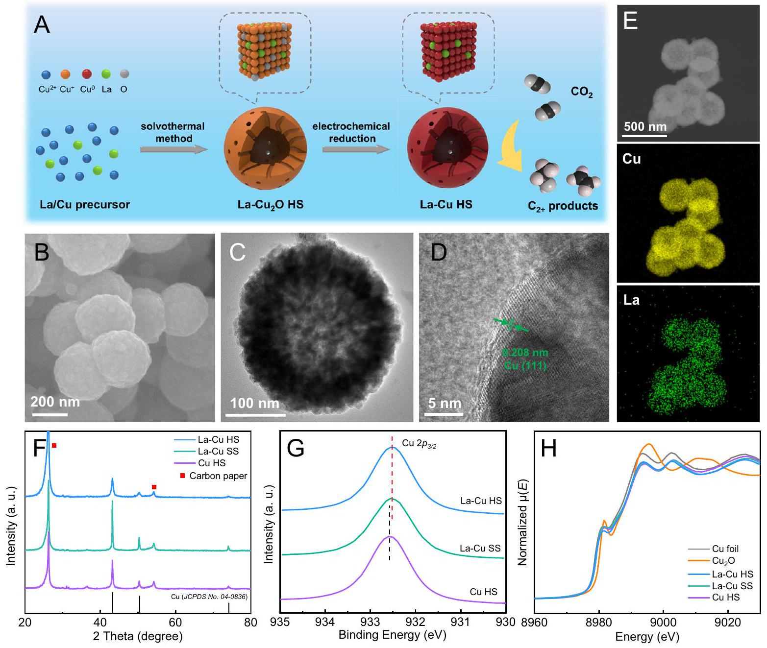
تم تخليق محفز La-Cu HS من خلال عملية من خطوتين وتم الحصول على هيكل كرة مجوفة مع قنوات في القشرة بنجاح من خلال آلية نضوج أوستوالد من الداخل إلى الخارج (الشكل 1A).. باختصار، المضاف إليه لا – كرة مجوفة ) تم الحصول عليها لأول مرة من خلال طريقة الحل الحراري في أوتوكلاف مبطن بتفلون. بعد ذلك، تم إعداد خضعت لعملية الاختزال الكهروكيميائي وتحولت في الموقع إلىفي خلية تدفق مزودة بقطب كهربائي لتشتت الغاز (GDE). أظهرت صور المجهر الإلكتروني الماسح (SEM) والمجهر الإلكتروني الناقل (TEM) (الأشكال S1، S2) أنامتلك شكل كرة مجوفة بمتوسط قطر يبلغ حوالي 300 نانومتر، وكان للغلاف هيكل قنوات مسامية واضح. أكدت تجربة إيزوثرم امتصاص-إزالة النيتروجين أنكان له هيكل مسامي متوسط وكان حجم المسام الأولي حوالي 5 نانومتر (الشكل S3). المسافة الشبكية الواضحة 0.246 نانومتر التي تتوافق مع مسافة مستوى الشبكة لـتم ملاحظة الوجه (111) في صورة المجهر الإلكتروني عالي الدقة (HRTEM) وأنماط حيود الأشعة السينية (XRD) (الشكل S4) وطيف التحليل الطيفي للأشعة السينية (XPS) (الشكل S5) أيضًا أشارت إلى أن أنواع النحاس في الـ HS كانت . بالإضافة إلى ذلك، أشارت خرائط مطيافية الأشعة السينية المشتتة للطاقة (EDS) إلى أن وعناصر O موزعة بشكل متساوٍ فيHS (الشكل S6).
بعد عملية الاختزال الكهروكيميائي، لم يُلاحظ أي تغيير واضح في الشكل من صور SEM و TEM (الشكل 1B، C). كانت المسافة بين الحواف الشبكية 0.208 نانومتر، والتي يمكن أن تُنسب إلى وجه Cu (111) (الشكل 1D). أظهرت خرائط EDS الموضحة في الشكل 1E توزيعًا متسقًا لعناصر Cu و La، مما يشير إلى وجود تشبع موحد لـ La في الهيكل بأكمله. تم تحديد محتوى La، من خلال EDS، بـالذي يتماشى بشكل وثيق معتم الحصول عليها عبر مطيافية الانبعاث الضوئي بالبلازما المقترنة بالحث (ICP-OES). للمقارنة، تم استخدام النحاس المخلوط باللانيوم مع شكل الكرة الصلبة (بدون قنوات، La-Cu SS) و المحفز النحاسي مع شكل الكرة المجوفة (بدونتم إعدادها أيضًا من خلال طريقة مماثلة (الأشكال S7، S8). كما أثبتت أنماط XRD تحولإلى Cu بعد عملية الاختزال الكهروكيميائي، بينما لم تُلاحظ أي قمم تتعلق بأنواع La (الشكل 1F). الـ Laتم عرض طيف XPS لـ La-Cu HS و La-Cu SS في الشكل S9،المنطقة تحتوي على مكونات دوران-مدار مفصولة جيدًا. طاقة الربط لـذروة لـ و هو 835.0 إلكترون فولت، مما يشير إلى أن نوع اللانثانيد في حالة مؤكسدة. بالإضافة إلى ذلك، انقسام، يُشار إليه بـ، تم الإشارة إليه في الشكل S9. يمكن ملاحظة أن و أظهر المماثلالذي هو أصغر من ذلك لـ و ، مما يشير إلى حالة الأكسدة لعنصر اللانثانوم و يختلف عن ذلك من و . أظهرت طيف LMM لثقب النحاس أن النحاس ظهر بشكل رئيسي في حالة معدنية في جميع العينات الثلاث (الشكل S10). ومن الجدير بالذكر أن طاقة الربط لـذروة و انتقل إلى طاقة ربط أقل مقارنة بتلك الخاصة بـ Cu HS (الشكل 1G)، والذي تم نسبه إلى نقل الشحنة من La إلى Cu. يمكن تفسير هذه الظاهرة من خلال الكهربية السالبة الأعلى لـمن تلك الخاصة بـ La (1.10). بعد ذلك، قمنا بإجراء قياسات طيف الامتصاص بالأشعة السينية في الموقع (XAS) (الشكل S11). كانت طيف الامتصاص القريب من حافة الأشعة السينية (XANES) لـ La-Cu HS و La-Cu SS و Cu HS مشابهة لتلك الخاصة بورق النحاس (الشكل 1H)، مما يشير إلى أن الحالة الكيميائية للنحاس في المحفزات الثلاثة كانت، وهو ما يتماشى مع تحليل XPS. بالإضافة إلى ذلك، كان هناك وضوح في التنسيق فييمكن ملاحظته في طيف بنية الامتصاص الدقيقة للأشعة السينية الممتدة لتحويل فورييه (FT EXAFS) لـ La-Cu HS و La-Cu SS و Cu HS (الشكل S12)، مما يؤكد أكثر أن النحاس كان موجودًا في حالة معدنية في جميع المحفزات الثلاثة. للأسف، فشلنا في الحصول على إشارات فعالة من La XAS تحت ظروف التشغيل، بسبب انخفاض محتوى La في المحفزات. يمكننا فقط تحديد أنواع La في LaCu HS و La-Cu SS من خلال جمع بيانات XAS على الفور بعداختبار. طيف و تم جمعها كعينات مرجعية للمقارنة. كما كشفت عنطيف XANES عند حافة – (الشكل S13)، كانت شدة الخط الأبيض لـ La-Cu HS و La-Cu SS مشابهة ولكنها أقل من تلك الخاصة بـ و . وقد اقترح أن نوع لا في و كان مشابهًا، لكنه كان مختلفًا عن تلك الموجودة في و ذروة رئيسية واحدة حواليتم ملاحظته في طيف FT EXAFS لـ La-Cu HS و La-Cu SS، والذي تم نسبه إلى تنسيق La-O. لا يوجد قمة تنسيق La-La عند حواليفي و ، مما يؤكد أن نوع La موجود كنوع ذري منفرد في La-Cu HS و La-Cu SS دون تنسيق بعيد المدى مع مراكز La الأخرى. علاوة على ذلك، هناك قمة عند حواليفي طيف EXAFS لـ La-Cu HS و La-Cu SS FT، الذي يمكن أن
الشكل 1 | الشكل والمواصفات الهيكلية. A توضيح تخطيطي لتصنيع La-Cu HS. B صور SEM، (C) صور TEM، و(D) صور HRTEM لـ La-Cu HS. E خرائط EDS لـ (الأصفر والأخضر يمثلان عناصر النحاس واللانثانوم، على التوالي).أنماط XRD و(G)طيف XPS لـلا-كو SS، وطيف XANES عند حافة النحاس K في الموقع، وعينات المرجع. يتم تعيينه إلىتشتت. لذلك، فإن نوع لا في CuHS وهي شكل من أشكالالمواقع على سطح النحاس.
دراسات المحاكاة والتجارب
للتحقيق في مساهمة هيكل القناة المسامية في إثراءتركيز وتعزيز الرقم الهيدروجيني المحلي، قمنا بإجراء دراسة مقارنة بين الكرة المجوفة ذات الهيكل القنوي المسامي في الغلاف والكرة الصلبة بدون قنوات من خلال محاكاة العناصر المحدودة باستخدام برنامج COMSOL Multiphysics. الكتلةتم ضبط التركيز عند 3 م. قمنا بمحاكاةتوزيع التركيز على سطح الكرة المجوفة مع القنوات، والكرة الصلبة، وداخل قنوات الغلاف تحت تيارات مختلفة. أظهرت النتائج أنتركيز على سطح الكرة المجوفة ذات القنوات والكرة الصلبة يزداد مع زيادة التيار (الشكل S14 والشكل 2A، B)، بينما أظهر سطح الكرة المجوفة ذات القنوات ارتفاعًا أكبر بكثير.تركيز أكثر من سطح الكرة الصلبة تحت نفس التيار. في داخل القنوات،كانت التركيزات أعلى بالقرب من السطح الخارجي وتتناقص تدريجياً من الخارج إلى الداخل. في الوقت نفسه، قمنا أيضًا بمحاكاة توزيع الشحنة السلبية على الكرة المجوفة ذات هيكل القنوات المسامية في القشرة وهيكل الكرة الصلبة بدون قنوات باستخدام برنامج COMSOL. أظهرت الشكل S15 تركيزًا محليًا بارزًا للشحنة على سطح الكرة المجوفة تحت جميع ظروف التيار، مع ملاحظة كثافة شحنة أعلى بشكل ملحوظ في محيط القنوات. تراكم الشحنات السلبية بالقرب من القنوات قد يجذبتسهيل انتشارإلى القنوات. للتحقق بشكل أكبر من قدرة هيكل الكرة المجوفة على إثراءقمنا بقياس طيف XPS لـ K 2 p على GDE المحملة بـ La-Cu HS و La-Cu SS، بعدتحت نفس الظروف (الشكل 2C). من الجدير بالذكر أنه لا توجد قمم تتوافق معتم العثور على الراسب في أنماط XRD للقطب بعدالخفض (الشكل S16)، ودرجة حموضة الإلكتروليت بعدكان 0.9، مما قد يستبعد وجودترسب على سطح GDE. أظهرت نتائج XPS زيادة ملحوظة فيالمحتوى على GDE المحمّل بـ La-Cu HS مقارنةً بالمحمّل بـ La-Cu SS، مما يثبت تجريبيًا استنتاج نتائج المحاكاة. التركيز المرتفع لـيساهم في تثبيط HER.
من ناحية أخرى، قمنا أيضًا بمحاكاة قيمة pH للكهارل بالقرب من سطح الكرة المجوفة والكرة الصلبة وكذلك داخل القنوات في غلاف الكرة المجوفة عند تيارات مختلفة. تم تعيين قيمة pH للكهارل في bulk على 1. كما هو موضح في الشكل S17، يمكن للكرة المجوفة أن تشكل بيئة ميكروية قلوية بالقرب من السطح عند تيار منخفض. عند كثافة تيار -700 مللي أمبير، تم توليد بيئة قلوية عالية بالقرب من سطح الكرة المجوفة مع القنوات، ويمكن أن تصل قيمة pH القصوى إلى 13.7، بينما قيمة pH للكرة الصلبة هي فقط 11.8 (الشكل 2D). كانت الظاهرة أكثر وضوحًا عند -900 مللي أمبير، ويمكن أن تبقى قيمة pH فوق 13 حتى على بعد 300 نانومتر من سطح الكرة المجوفة مع القنوات (الشكل 2E). علاوة على ذلك، داخل
الشكل 2 | دراسات المحاكاة والتجربة. أ من اليسار إلى اليمين هيتوزيع التركيز على سطح الكرة الصلبة، والكرة المجوفة ذات القنوات، وداخل قنوات الكرة المجوفة عند -700 مللي أمبير. ب من اليسار إلى اليمين هو توزيعتركيز على سطح الكرة الصلبة، الكرة المجوفة، وداخل قنوات الكرة المجوفة عند -900 مللي أمبير. طيف XPS لـ La-Cu HS و La-Cu SS بعداختبار فييحتوي على محلول إلكتروليتي 3 م كCl.
د من اليسار إلى اليمين هو توزيع الرقم الهيدروجيني في الإلكتروليت بالقرب من سطح الكرة الصلبة، الكرة المجوفة، وداخل قنوات الكرة المجوفة عند -700 مللي أمبير. هـ من اليسار إلى اليمين هو توزيع الرقم الهيدروجيني في الإلكتروليت بالقرب من سطح الكرة الصلبة، الكرة المجوفة، وداخل قنوات الكرة المجوفة عند -900 مللي أمبير. طيف SERS في الموقع لـ (F) La-Cu HS و (G) La-Cu SS تحت كثافات تيار مختلفة في 0.05 م.يحتوي على محلول إلكتروليتي 3 م كCl. يمكن أن تظهر القنوات أيضًا بيئة قلوية عالية عندما يكون التيار أكبر من -700 مللي أمبير. وقد تم الإبلاغ عن أن تفاعل التوازن بين الناتجويمكن أن تعكس الأنواع درجة الحموضة المحلية بالقرب من سطح المحفز، وتساعد البيئة الدقيقة القلوية على تعزيز الحركة الأمامية لتوازن التفاعل نحوتشكيل. لذلك، قمنا بإجراء قياسات سطحية في الموقع- طيف رامان المعزز (SERS) لمراقبة الناتج ( ) و الأنواع فوق و في يحتوي على إلكتروليت 3 م كلوريد البوتاسيوم تحت كثافات تيار مختلفة (الشكل S18). كما هو موضح في الشكل 2F، من الواضح وتم الكشف عن القمم جميعها فوق La-Cu HS عند كثافات تيار مختلفة، مما يشير إلى توليدأنشأ القلوي الميكروبيئة. مع زيادة كثافة التيار، زادت الذروة لـأصبح أكثر بروزًا بينما بلغ الذروة لـأصبح أضعف، مما يدل على أن البيئة الدقيقة القلوية المرتفعة تدريجياً قد تشكلت. ومع ذلك، فإنويمكن ملاحظة القمم فوق طيف La-Cu SS فقط عند كثافة تيار كبيرة (الشكل 2 G)، ونسبة المساحة لـإلىكان أقل بكثير من ذلك في La-Cu HS. وبالتالي، قدمت نتائج SERS في الموقع دليلاً تجريبيًا على أن الكرة المجوفة ذات الهيكل القنوي المسامي تسهل تشكيل بيئة ميكروية شديدة القلوية بالقرب من سطح المحفز، والتي قد تلعب دورًا حاسمًا في تثبيط HER وتعزيزتفاعل الاقتران.
الكهربائية التحفيزيةأداء
تم استخدام خلية تدفق مزودة بـ GDE لتقييمأداء، ، وCu HS تحت كثافات تيار مختلفة، وتم استخدام محلول مائي يحتوي على 3 م من كلوريد البوتاسيوم ككاثوليت و تم الكشف عنها في الطور الغازي بواسطة كروماتوغرافيا الغاز، والفورمات، والإيثانول، والأسيتات وتم الكشف عن -بروبانول في المنتجات السائلة من خلالطيف الرنين المغناطيسي النوويتظهر الشكل 3Aالمنتجات فوق ، و Cu HS عند كثافات التيار التي تتراوح من -300 إلى . أظهر La-Cu HS فوق في نطاق كثافة التيار الكامل الحالي، و الحد الأقصىوصلتفي، الذي يتوافق مع كثافة التيار الجزئي للمنتجات ( ) مرتفعة كما (الشكل 3B). والأهم من ذلك، أنها لا تزال تحتفظ بمستوى عالٍمنفي، و يمكن أن تصلأداءكان أفضل بكثير من ذلك لـ، و Cu HS . الـ FE منتم قمعه داخلفي نطاق كثافة التيار الحالي بالكامل (الشكل S19)، بينما تجاوزت فوق و Cu HS عند كثافة تيار عالية. الشكل 3 C يكشف عن ارتفاع نسبة 9.1 على، وهو أكبر بمقدار 2.0 مرة و 4.3 مرة من ذلك على SS و Cu HS ، على التوالي. بالإضافة إلى La ، تأثير إضافة عناصر LM أخرى إلى Cu على -إلى-تمت دراسة المنتجات أيضًا. لقد قمنا بتطعيم، وتحويل Er إلى Cu باستخدام نفس الطريقة كما واختبرواالنشاط تحت ظروف متطابقة من الإلكتروليت وكثافة التيار. تم تقديم توزيع المنتجات في الشكل S20، وأشارت النتائج إلى أن La-Cu أظهر أعلىمنتجات FE.
استنادًا إلى النتائج أعلاه، يمكننا أن نجد أن كل من القنوات داخل القشرة والتشويب باللانيوم قد عززاانتقائية المنتجات. للتحقيق في تأثير مادة الدوبان لانيوم علىالأداء، قمنا بإعداد سلسلة من محفزات La-Cu HS بمحتوى La متنوع من خلال تغييرنسب التغذية (النسب المولية لـ، ، و 0.4 )، ومحتويات اللانثانوم التي تم تحديدها بواسطة ICP-OES كانت، و على التوالي (الأشكال S21-S23). الـ
الشكل 3 | التحفيز الكهربائيالأداء. أ الـ FEs لـ المنتجات، (ب) كثافة التيار الجزئي للمنتجات و (C)الانتقائية على La-Cu HS و La-Cu SS و CuHS تحت كثافات تيار مختلفة.المنتجات FE على La-Cu HS مع اختلافنسبة عند. E المنتجات FE فوق في 0.05 ممحلول مائي يحتوي على تركيزات مختلفة من KCl في.
القيم هي المتوسطات وأشرطة الخطأ تشير إلى الانحراف المعياري.نسخ).المنتجات FE ، SPCE وإجمالي المنتجات SPCE منتحت مختلفمعدل تدفق الغاز عندالاستقرار طويل الأمد لـ La-Cu HS عند كثافة تيار ثابتة منتم غسل القطب، ثم تجفيفه وتم تجديد المحلول الكهربائي على فترات كل 5 ساعات. أداء الـمع محتوى مختلف من مادة الدوبينغ La فيمُعَرض في الشكل 3D والشكل S24، ويمكن ملاحظة علاقة على شكل بركان بينمحتوى منتجات FE و La المضافة. الحد الأقصىالمنتجاتتم الحصول عليه عندماالنسبة هي 0.3، مما يؤكد أن التخصيب المناسب للانديوم في النحاس سيعززانتقائية المنتجات. مقارنة مع المحفزات الكهربائية المتطورة المستخدمة في الأحماضالأنظمة،أظهرت كثافة تيار الجهد الكهربائي وكثافة التيار الجزئي أعلى بكثير من أجل توليدالمنتجات (الجدول S1).
تأثيرتركيز علىأداءتمت دراسة Cu HS أيضًا. فقطتم الكشف عنه عندماتم استخدام محلول مائي ككاثوليت (الشكل 3E، الشكل S25). انخفض FE تدريجياً مع زيادة تركيز في 0.05 ممحلول مائي، وكان منخفضًا كمافي. في هذه الأثناء، التحسن الملحوظ في تم الحصول على انتقائية المنتجات (58.1%) في، و زادت منتجات FE بشكل واضح كما زاد التركيز بشكل أكبر. بشكل عام، تشير النتائج أعلاه إلى أن المستوى العاليالتركيز مفيد لقمع HER وتعزيزانتقائية المنتجات في إلكتروليت حمضي.
بالإضافة إلى ذلك، يمكن أن يقلل استخدام النظام الحمضي من تكوين الكربونات، وبالتالي فهو مفيد في التغلب على قيود استخدام الكربون التي لوحظت في المحاليل المحايدة والقلوية. عند تقليل معدل التدفق لـمن 40 إلى 3 سنتيمتر مكعب قياسي في الدقيقة (sccm)، زادت SPCE لجميع المنتجات على La-Cu HS منإلىفي، و SPCE لـ يمكن أن تصل المنتجاتعند 3 SCCM (الشكل 3F، الشكل S26). كان أعلى من الأنظمة المبلغ عنها في الإلكتروليت القلوي/المحايد، مما يبرز مزايا النظام التحفيزي. كما قمنا بتقييم الاستقرار على المدى الطويل لـفي نظام حمضي عندلتخفيف مشكلة الفقد التدريجي للخصائص غير القابلة للذوبان في الماء لـ GDE،تمت المقاطعة كل 5 ساعات وتمت إزالة GDE، وغسلها بالماء المقطر، ثم تجفيفها تحتالغلاف الجوي. كما هو موضح في الشكل 3G، لم يُلاحظ أي تدهور ملحوظ في الجهد المقاس وظل فوقبعد العملية لمدة 40 ساعة، مما يدل على المتانة الجيدة. الشكل والبنية لـ La-
تم الحفاظ على Cu HS بشكل جيد بعد اختبار الاستقرار (الشكل S27). علاوة على ذلك، أكدت خريطة EDS أن عنصر La لا يزال موجودًا على السطح منبعد (الشكل S28)، وكان محتوى اللانثانوم “، مشابه لمحتوى “Laقبلأكدت تقنية XPS أنه لم يتم ملاحظة تغييرات ملحوظة في تركيب العناصر بعد التحليل الكهربائي (الشكل S29). وأشارت نتيجة ICP-OES إلى أن محتوى اللانثانوم في الإلكتروليت بعديمكن تجاهله، مما يؤكد أن الأنواع الذرية من اللانثانوم في المحفز كانت مستقرة خلالمعًا،أظهر وعدًا كبيرًا للتطبيقات التي تتعلق بتحويلإلىالمنتجات في النظام الحمضي.
الدراسات الميكانيكية
من أجل توصيف الوسطاء خلالتم إجراء طيف الامتصاص بالأشعة تحت الحمراء المعزز بواسطة الانعكاس الكلي المخفف في الموقع (ATR-SEIRAS) (الشكل S30) على و Cu HS عند مختلف الجهود المطبقة (الشكل 4A، B). القمم عند حوالي ، الذي يتوافق مع *CO على الوسائط، ظهرت على كل من La-Cu HS و Cu HS. كانت شدة الذروة لـ *CO على La-Cu HS عند -0.9 و -1.0 فولت أقوى بشكل ملحوظ من تلك الموجودة على CuHS، مما يشير إلى أنكان HS فعالاً للغاية في التنشيط والتقليلإلى *CO. ومع ذلك، زادت شدة ذروة *CO في طيف Cu HS بسرعة مع ازدياد السالبية في الجهد المطبق، وتجاوزت الشدة الملاحظة في طيف La-Cu HS ضمن نطاق الجهد المطبق من -1.1 إلى -1.3 فولت. في الوقت نفسه، ظهرت ذروة *OCCO عندأظهر أنحدث تفاعل الاقتران من خلال تفاعل ثنائي أكسيد الكربون. لقد دمجنا الـذروة أول أكسيد الكربون والأكسجينذروة CCO، وقارنت نسبة مساحة الذروة لـإلى *CO ضمن نطاق الجهد المطبق من -1.1 إلى -1.3 فولت. توضح الشكل 4 C أن نسبة مساحة الذروة فيزاد الطيف تدريجياً مع زيادة السالبية في الجهود المطبقة، وهو ما كان أعلى بشكل ملحوظ من ذلك الخاص بـ Cu HS. وهذا يشير إلى أنسهلت اقتران *CO إلى *OCCO عند جهود كهربائية أعلى. على النقيض من ذلك، كان من المحتمل أن يتراكم *CO على سطح Cu HS بسبب نشاطه التحفيزي المنخفض في اقتران C-C.. لذلك، أكدت نتائج تجربة ATR-SEIRAS في الموقع أن إضافة اللانثانوم تسهل توليد *CO و
الشكل 4 | الدراسات الميكانيكية. تم تسجيل ATR-SEIRAS في الموقع عند إمكانيات مختلفة لـ (A) و (ب) النحاس HS خلال نسبة مساحة الذروة لـOCCO إلىCO كدالة لجهود مختلفة لـو Cu HS . D العلاقة بين تغير الطاقة الحرة لجيبس لـ 2CO إلى Oخطوة CCO وتناول المنشطات محتوى.مخططات الطاقة الحرة لجيبستقليل إلىعلى أسطحونماذج النحاس، على التوالي.، و منو Cu ، على التوالي. عملية الاقتران خلال-إلى-المنتجات. بعد ذلك، تم إجراء تجارب XAS في الموقع لمراقبة الهيكل المحلي للنحاس خلال تحت أوقات تفاعل مختلفة. كما هو موضح في الشكل S31، كان طيف XANES لـ La-Cu HS مشابهًا لطيف ورقة النحاس، ولم يُلاحظ أي فرق واضح كما زاد وقت رد الفعل. علاوة على ذلك، فقط القمم التي تتوافق معتمت ملاحظة التنسيق في جميع طيف FT EXAFS، مما يشير بشكل إضافي إلى أن الهيكل المحلي للنحاستم الحفاظ على استقراره خلال.
للمزيد من التحقق من الاستنتاج المذكور أعلاه، قمنا بإجراء حسابات من المبادئ الأولى استنادًا إلى نظرية الوظائف الكثافة (DFT). نموذج النحاس المضاف إليه اللانثانوم (تم بناء ( ) من خلال إدخال ذرات لا و أو فيسطح الكريستال لتشكيل مواقع La-O-Cu (الشكل S32). من أجل دراسة تأثير محتوى ذرة La علىتفاعل الاقتران، قدمنا، و 6 ذرة لا و أو إلىسطح (المشار إليه بـ )، تم بناء نماذج بمحتويات متغيرة من ذرات اللانثانوم والأكسجين، وحُسِبَت تغيرات الطاقة الحرة لجيبس في خطوة to-O*CCO ( ). من الجدير بالذكر، لأخذ تأثير و على التفاعل مع تقليل التعقيد الحسابي في الوقت نفسه، قمنا بتبسيط النموذج من خلال وضع واحدمرطب بستة جزيئات ماء على سطح النموذج المُنشأ (الأشكال S33-S37)كما هو موضح في الشكل 4D، مع زيادة عدد ذرات اللانثانوم،تقلص تدريجياً. عندما كان عدد ذرات اللانثانوم المخدرة 4،وصلت إلى أدنى قيمة لها وهي 0.17 إلكترون فولت. أدى زيادة عدد ذرات اللانثانوم المضافة إلى زيادةأشارت النتائج إلى أن مستوى معتدل من إضافة اللانثانوم كان مواتيًا لـعملية الاقتران، التي تتماشى مع العلاقة على شكل بركان التي لوحظت في التجارب بينمحتوى منتجات FE و La المضافة. بالإضافة إلى ذلك، قمنا بإجراء محاكاة الديناميكا الجزيئية من أولى المبادئ (AIMD) على 4La-Cu تحت 300 كلفن (الشكل S38)، وأكدت النتائج الاستقرار القوي لتكوين 4La-Cu، حيث يمكن أن توجد ذرات La و O علىسطح بشكل مستقر.
الشكل 4E يوضح مخططات الطاقة الحرة لجيبس لـإلى * OCCO على نماذج Cu و 4La-Cu (الأشكال S39، S40). الـ *كانت التكوين عملية طاردة للحرارة، مما يشير إلى أن كانت الجزيئة مفضلة للامتزاز على سطح 4La-Cu. تكوين OCCO من 2كان أول أكسيد الكربون هو الخطوة المحددة المحتملة لنموذج النحاس. ومع ذلك، عندما تم إضافة 4 ذرات لانيوم إلى سطح النحاس، فإنانخفضت من 1.39 إلكترون فولت إلى 0.17 إلكترون فولت، مما يوضح أكثر أن الشوائب من اللانثانوم كانت مفيدة لـعملية الاقتران، وبالتالي تحسينانتقائية المنتجات. تفاعل الهيدروجين على النحاس وتم حسابها (الشكل S41)، حاجز الطاقة فوقكان 0.36 إلكترون فولت، وهو أكبر من ذلك على“، مما يشير إلى أن إضافة اللانثانوم مفيدة في كبح تفاعل تقليل الهيدروجين. بالإضافة إلى ذلك، اعتمدنا على الفرق بين الإمكانيات الحرارية الديناميكية المحدودة ( ) لـ -إلىأوكّو وهرلمقارنة انتقائية و كلما كان أكثر إيجابيةيتوافق مع انتقائية أعلى نحوالحد من. الخطوة المحتملة المحددة لـ-إلىكان OCCO فوق Cu 2CO إلى Oخطوة CCO، التي تتوافق معمن -1.39 إلكترون فولت، بينما كان *إلى * COOH تخطى، مما يتوافق مع من -0.90 إلكترون فولت. الـ و منوتم عرض Cu في الشكل 4F. تشير النتيجة إلى أنكان أكثر ملاءمة للخضوع مقارنة بالنحاس.
نقاش
باختصار، تم تصنيع La-Cu HS بنجاح وتم التحقق من كونه المحفز الفعال لـإلىالمنتجات في الإلكتروليت الحمضي القوي. أظهرت أداءً متميزًامنتجات FE من بكثافة تيار جزئية من ، قيمة SPCE عالية منواستقرار ملحوظ. علاوة على ذلك،يمكن الاحتفاظ بالمنتجات FE فوقعند كثافة تيار عالية منأظهرت الدراسات المفصلة أن هيكل القناة يمكن أن يركزوالأنواع على السطح وفي قنوات المحفز لقمع تفاعل الهيدروجين وتقوية عملية اقتران الكربون. في الوقت نفسه، فإن إضافة اللانثانوم ساعدت في تعزيز *CO توليد وتقليل حاجز الطاقة لـتفاعل الاقتران، مما يؤدي إلى النشاط العالي لـ-إلى-المنتجات بشكل كبير. يوفر هذا العمل استراتيجية فعالة للترويجالأداء في نظام حمضي من خلال دمج تعديل البيئة الدقيقة وزيادة النشاط التحفيزي الجوهري. نحن نعتقد أن ذلك سيساهم في دفع المزيد من الابتكار والتطوير لتحويل واستخدام.
طرق
المواد
نترات النحاس ثلاثي الهيدراتنقاءنيتريد اللانثانوم سداسي الماءنقاءكلوريد البوتاسيوم (KCl، نقاء )، الفينول (نقاء )، صوديوم 2، 2-دايميثيل-2-سيلا بنتان-5-سولفونات (DSS، 99%)، أكسيد الديوتيريوم ( نقاء > 99.9)، إلكترود انتشار الغاز (GDE، YLS-30)، ورقة بلاتين، تشتت نافيون D-521 ( )، وغشاء تبادل البروتون (N117) تم شراؤه من شركة ألفا أيسر الصين المحدودة. الإيثيلين جلايكولنقاء ) ، حمض الكبريتيك ( نقاء ) تم الحصول عليها من شركة ألفا أيسر الصين المحدودة.تم توفير (99.999%) من قبل شركة بكين للأدوات التحليلية. تم استخدام جميع المواد مباشرة دون أي تنقية إضافية.
تحضير المحفزات
المشوب باللاندنيومكرة مجوفةتم تصنيعها بواسطة الطريقة الحرارية المائية، وأدى عملية إعادة التبلور (أي، آلية نضوج أوستوالد من الداخل إلى الخارج) إلى إخلاء النواة، مما أسفر عن الحصول على هيكل كرة مجوفة مع قنوات في القشرة بنجاح دون استخدام قوالب. أولاً، تم تحضير خليط يتكون من و تم إضافة إلى 20 مل من الإيثيلين جلايكول، وتم التحريك طوال الليل. ثم، تم نقل المزيج أعلاه إلى وعاء أوتوكلاف من الفولاذ المقاوم للصدأ مبطن بتفلون سعة 50 مل وتم تسخينه عندلمدة 6 ساعات في حمام زيت تحت تحريك مستمر. بعد أن تبرد بشكل طبيعي إلى درجة حرارة الغرفة، تم غسل الراسب الناتج عدة مرات بإيثانول وماء منزوع الأيونات، تلاه التجفيف عندبين عشية وضحاها. تم الحصول على كرة مجوفة من النحاس المضاف إليه اللانثانوم (La-Cu HS) من خلال إجراء اختزال كهربائي لـداخل خلية تدفق. بعدتم توزيعها على GDE، كثافة التيار تم تنفيذها لمدة 300 ثانية.محلول مائي يحتوي على 3 م كClتم استخدام المحلول المائي ككاثوليت وأنوليت، على التوالي. معدل التدفق لـتم التحكم في الغاز ليكون 40 سنتيمتر مكعب قياسي في الدقيقة (sccm). لتخليق La-Cu HS بمحتوى لا مختلف، تم استخدام نفس الإجراء مع اختلافنسب في المواد الخام.
تم تحضير كرة صلبة من النحاس المضاف إليها اللانثانوم (La-Cu SS) باستخدام إجراء مشابه لذلك لـ، مع الاختلاف الوحيد وهو تعديل درجة الحرارة خلال الطريقة السولفثرمالية، التي تم ضبطها علىعند درجات الحرارة المنخفضة، تكون معدلات النواة ونمو الجسيمات بطيئة، مما يفضل تشكيل الهيكل الصلب من الناحية الحركية بناءً على آلية نضوج أوستوالد غير العادية من الداخل إلى الخارج. تم تخليق Cu HS باتباع نفس الإجراء المستخدم في La-Cu HS، باستثناء أن الأوتوكلاف المصنوع من الفولاذ المقاوم للصدأ والمبطن بتفلون تم تسخينه في فرن ودونإضافة.
توصيف المواد
تم إجراء تحليل المجهر الإلكتروني الماسح (SEM) باستخدام جهاز HITACHI S-8020. تم إجراء المجهر الإلكتروني الناقل (TEM) والمجهر الإلكتروني الناقل عالي الدقة (HRTEM) وتحليل طيف الطاقة المشتت (EDS) باستخدام جهاز JEOL JEM-2100F. تم إجراء تحليل حيود الأشعة السينية (XRD) باستخدام جهاز حيود الأشعة السينية (النموذج D/MAX2500، ريجاكا) معالإشعاع. نطاق المسح لـتم تعيينه منإلىبمعدل مسحتم إجراء تحليل طيف الإلكترونات الضوئية بالأشعة السينية (XPS) باستخدام جهاز Thermo Fisher Scientific ESCA
أداة مختبر 250Xi. استخدمت قياسات XPS 200 واط من الألمنيوم أحادي اللونإشعاع تحت ضغطتم معايرة طيف XPS باستخدام قمة C 1s عند 284.4 eV. تم تسجيل بيانات امتصاص الأشعة السينية عند حافة Cu K للمواد الحفازة في وضع الفلورية عند خط الشعاع 1W2B في منشأة الإشعاع المتزامن في بكين (BSRF). تم تحليل جميع الأطياف المجمعة باستخدام برامج Athena وArtemis ضمن حزم برامج IFEFFIT.
الكهربائية التحفيزيةتقليل
لإعداد القطب العامل، تم تحضير حبر موحد من المحفز عن طريق دمج 1 ملغ من المحفز المُصنَّع، من الإيزوبروبانول، و من تشتت نافيون D-521 ( ). تم تعريض الخليط للتسونك لمدة 30 دقيقة لضمان التجانس. بعد ذلك، تم وضع حبر المحفز بعناية على GDE من في المنطقة بواسطة ميكروببيتيت، مستهدفًا تحميل المحفز بحواليتم إجراء التحقيقات الكهروكيميائية باستخدام محطة عمل كهروكيميائية CHI660E مزودة بمضخم تيار عالي، CHI680C. تم استخدام تكوين خلية تدفق، يتكون من غرفة غاز، وغرفة كاثودية، وغرفة أنودية. تم وضع القطب العامل بين غرفة الغاز والغرفة الكاثودية، بينما تم وضع القطب المضاد في الغرفة الأنودية. كانت هناك غشاء تبادل بروتونات منفي المنطقة التي تفصل بشكل فعال بين غرف الكاثود والأنيود. تم استخدام قطب كهربائي Ag/AgCl كقطب مرجعي، وتم استخدام ورقة بلاتين كقطب مضاد. المقاومة الأوميةالخلية كانتالذي تم قياسه بواسطة محطة العمل الكهروكيميائية. الكاثوليت، محلول مائي بتركيز 3 م من كلوريد البوتاسيوم (تم تحديد قيمة الرقم الهيدروجيني بواسطة مقياس الرقم الهيدروجيني المعاير)، والمحلول الأنودي، تم تدوير المحلول المائي بشكل مستمر عبر غرف الكاثود والأنود، على التوالي، باستخدام مضخات بيرستالتية. تم ضبط معدلات التدفق للكاثوليت والأنوليت على و ، على التوالي. للتحكم في تدفق الغاز، تم استخدام جهاز التحكم في تدفق الكتلة، للحفاظ على معدل تدفقعبر غرفة الغاز.
تم جمع المنتجات الغازية الناتجة عن التفاعلات الكهروكيميائية باستخدام حقيبة غازية وتم تحليلها لاحقًا باستخدام كروماتوغرافيا الغاز (GC). كانت الأداة المستخدمة في كروماتوغرافيا الغاز هي GC 7890B، المجهزة بكاشف الموصلية الحرارية (TCD). تم استخدام الأرجون كغاز حامل أثناء التحليل. لتحليل المنتج السائل،تم استخدام مطيافية الرنين المغناطيسي النووي (NMR). تم إجراء قياسات NMR على جهاز مطياف Bruker Advance III 400 HD باستخدام الديوتيروكسايد ( ) كمذيب. المركب المرجعي المستخدم للإيثانول وحمض الأسيتيك و n-بروبانول كان DSS (حمض 2،2-ثنائي ميثيل-2-سيلا بنتان-5-سولفونيك)، بينما كان الفينول هو المرجع للفورمات. تم حساب الكفاءة فارادايك (FE) للمنتجات بواسطة المعادلة:
أينيمثل عدد الإلكترونات المنقولة لتكوين المنتج،هو عدد مولات المنتج المستخرج من جهاز الكروماتوغرافيا الغازية/الرنين المغناطيسي النووي هو ثابت فاراداي ( ) و الـ هو مقدار الشحنة التراكمية المسجلة بواسطة محطة العمل الكهروكيميائية.
التم حساب كفاءة التحويل في تمريرة واحدة (SPCE) بالمعادلة التالية:
حيث I هو كثافة التيار،نسبة المولات منإلىمنتج هو الكفاءة الفارادائية لـ منتجهو عدد نقل الإلكترونات لـجزيء المنتج.
طيف رامان المعزز بالسطح في الموقع (SERS)
تم إجراء القياس باستخدام مجهر رامان Horiba LabRAM HR Evolution ضمن إعداد خلية تدفق معدلة. كانت GDE المحملة بالمواد الحفازة تعمل كالكاثود، بينما كانت تم استخدام قطب AgCl و سلك Pt كقطب مرجعي وقطب مضاد، على التوالي. في خلية التدفق، كانت الكاثوليت تتكون منمحلول مائي يحتوي على 3 م كCl، بينما كان الأنوليت يتكون منمحلول مائي. تم تدوير هذه المحاليل باستمرار عبر غرف الكاثود والأنود باستخدام مضخات بيرستالتية تعمل بمعدلتم استخدام ليزر بطول موجي 785 نانومتر للقياسات، وتم تسجيل إشارات رامان بوقت تكامل قدره 20 ثانية ومتوسط مسحين. تم إجراء SERS في الموقع من خلال تطبيق كثافات تيار مختلفة تتراوح من 5 إلىإلى القطب العامل. ستؤدي كثافات التيار العالية خلال اختبارات رامان في الموقع إلى تقليل إشارة SERS بسبب التطور الكبير لمنتجات الغاز. يجب أيضًا ملاحظة أن نتائج SERS تعمل كدليل على الرقم الهيدروجيني الواجهاتي في الإعداد المعدل.
الطيف الكهرومغناطيسي لامتصاص الأشعة تحت الحمراء المعزز بسطح الانعكاس الكلي المخفف في الموقع (ATR-SEIRAS)
تم إجراء القياس في خلية كيميائية كهربائية معدلة، حيث تم إسقاط المحفز على بلورة الجرمانيوم ATR المودعة بطبقة من الذهب، والتي استخدمت كقطب عمل.تم استخدام قطب كهربائي وسلك بلاتينيوم كقطب مرجعي وقطب مضاد، على التوالي. تم دمج الخلية في جهاز مطياف FTIR NICOLET 6700 المزود بكاشف MCT المبرد بالنيتروجين السائل.تم استخدام محلول مائي بتركيز 3 م من KCl كمحلول إلكتروليتي وتم تدويره عبر غرفة الكاثود وغرفة الأنود بواسطة مضخات بيرستالتية بمعدل.
قياسات XAS في الموقع
تم إجراء القياس على خلية تدفق مصممة خصيصًا، وتم استخدام المحفز المحمّل على GDE كقطب عمل،تم استخدام إلكترود و سلك بلاتيني كإلكترود مرجعي وإلكترود مضاد، على التوالي. كانت الكاثوليت تتكون من 0.05 ممحلول مائي يحتوي على 3 م كCl، بينما كان الأنوليت يتكون منمحلول مائي. تم تدوير هذه المحاليل باستمرار عبر غرف الكاثود والأنود في خلية التدفق باستخدام مضخات بيرستالتية، تعمل بمعدل تدفق قدره. تم تسجيل البيانات في وضع الفلورية مع تدفق غازي مستمر. الـتم جمع طيف الحافة للعناصر من العينات بطريقة خارجية. تم تحميل المحفز على GDE وتم إجراءاختبار عند كثافة تيارلمدة 400 ثانية في خلية التدفق، ثم تم إخراج GDE من خلية التدفق وبدأت على الفور عملية جمع البيانات لـطيف الحافة باستخدام وضع الفلورية.
محاكاة COMSOL متعددة الفيزياء
تم تطوير نموذج ثلاثي الأبعاد لمجال كهربائي وتوزيع الأيونات باستخدام COMSOL لتوضيح توزيع أيونات البوتاسيوم في هياكل مختلفة. تم استخدام COMSOL Multiphysics 6.1 لوصف الهجرة، والترسيب، وتوزيع الجهد الكهروكيميائي، وعمليات نقل التيار للأيونات باستخدام نهج توزيع تيار تربيعي. استخدم النموذج جزيئات كروية بقطر 150 نانومتر لمحاكاة جزيئات النانو ذات السطح الأملس. بالإضافة إلى ذلك، تم إدخال مسام داخل قشرة الكرة المجوفة لمحاكاة الهيكل المسامي. تم محاكاة المجال الكهربائي، والتيار، وتوزيع الأيونات أثناء هجرة أيونات البوتاسيوم في نوعي العينات. تم الحفاظ على التركيز الأولي لأيونات البوتاسيوم في المحلول الكهربائي عند 3.0 م.كانت 0.1 م، مما يتوافق مع قيمة pH تبلغ 1. تم اعتبار النموذج ارتباطًا متعدد الفيزياء لمعادلة نيرنست-بلانك، والتي تحسب النقل الكتلي لجميع الأنواع:
أينهو تركيز الأنواعلـلـلـ هو التدفق، و هو معدل تفاعل الأنواع. كان التدفق مجموع التدفقات الناتجة عن الانتشار والهجرة:
أينهو تركيز وشحنة الأنواع، . ، و T تمثل ثابت فاراداي، وثابت الغاز، ودرجة الحرارة المطلقة ( )، على التوالي، و هو الجهد الكهروستاتيكي.
تم استخدام التيار الكهربائي لمحاكاة توزيع المجال الكهربائي، والصيغة لحساب المجال الكهربائي كما يلي:
ونموذج العازل يتبع القواعد:
أين هو الثابت الكهربائي للفراغ، هو الثابت العازل للمواد.
معدل تكوين الأنواعتم تحديده من تفاعل تقليل الماء وتوازن تفكك الماء باستخدام المعادلات:
أينهو معدلجيل هو ثابت معدل تفاعل اختزال الماء ( )، و هو ثابت معدل العكس لتفكك الماء ( ). معدل تم حساب الجيل بناءً على المعادلة:
أينو F هو كثافة التيار المطبق، وعدد نقل الإلكترون، والثابت فارادي، على التوالي.
حسابات نظرية الكثافة (DFT)
تم استخدام حسابات من المبادئ الأساسية استنادًا إلى نظرية الوظائف الكثيفة (DFT) في دراستنا.تم إجراء الحسابات ضمن تقريب التدرج العام (GGA) باستخدام صيغة بيردو-بورك-إرنزرهوف (PBE)لوصف النوى الأيونية وحساب الإلكترونات التكافؤية، استخدمنا إمكانيات الموجة المعززة المتوقعة (PAW).تم استخدام مجموعة أساس الموجة الطائرة مع حد طاقة حركية قدره 450 إلكترون فولت. للسماح بالاحتلالات الجزئية لأوربيتال كوهين-شام، استخدمنا طريقة التمويه الغاوسي بعرض 0.05 إلكترون فولت. بالنسبة لتحسينات الهندسة وحجم الشبكة، تم إجراء تكامل منطقة بريل.غاماعينات النقاط. استخدمت الحسابات المتسقة ذاتياً عتبة طاقة التقارب خلال عملية التحسين، تم تحسين كل من الهندسة وثوابت الشبكة من خلال فرض إجهاد أقصى قدرهعلى كل ذرة. للقضاء على
تم عادة إضافة طبقة فراغية بسمك 17 Å إلى الأسطح لتجنب التفاعلات الاصطناعية بين الصور الدورية. تم معالجة التفاعلات الضعيفة باستخدام طريقة DFT + D3، التي تتضمن تصحيحات تجريبية وفقًا لنظام غريمي. في حالة الأنظمة المغناطيسية، استخدمنا طريقة استقطاب الدوران. تم تعيين مستوى السطح المتساوي لكثافة الشحنة عند. تم حساب الطاقة الحرة غيبس لكل خطوة أساسية على أنها:
حيثهي الطاقة الإلكترونية عند 0 كلفن المحسوبة بواسطة DFT،هي مصطلح الطاقة عند النقطة الصفرية، وT هي درجة الحرارة المطلقة (هنا 298.15 كلفن). للحصول على حالة الحرارة والطاقة، تم استخدام الديناميكا الجزيئية الأولية المقيدة (AIMD) مع طريقة النمو البطيء. في بداية محاكاة الديناميكا الجزيئية، تم تسخين النماذج إلى 300 كلفن عن طريق تعديل السرعة على مدى 1.5 بيكوثانية ثم تم تحقيق التوازن عند 300 كلفن لمدة 5 بيكوثانية مع خطوة زمنية قدرها 2 فيمتوثانية.
توفر البيانات
البيانات التي تدعم الرسوم البيانية داخل هذه الورقة متاحة في ملف البيانات المصدر. البيانات الإضافية متاحة من المؤلفين عند الطلب. يتم توفير بيانات المصدر مع هذه الورقة.
References
Seh, Z. et al. Combining theory and experiment in electrocatalysis: Insights into materials design. Science 355, 146-158 (2017).
Tan, X., Sun, X. & Han, B. Ionic liquid-based electrolytes for electroreduction and electroorganic transformation. Natl. Sci. Rev. 9, nwab022 (2022).
Jin, S., Hao, Z., Zhang, K., Yan, Z. & Chen, J. Advances and challenges for the electrochemical reduction of to CO : From fundamentals to industrialization. Angew. Chem. Int. Ed. 60, 20627-20648 (2021).
Zhang, Y. et al. Self-polarization triggered multiple polar units toward electrochemical reduction of to ethanol with high selectivity. Angew. Chem. Int. Ed. 62, e202302241 (2023).
Zhu, Q. et al. Carbon dioxide electroreduction to products over copper-cuprous oxide derived from electrosynthesized copper complex. Nat. Commun. 10, 3851 (2019).
Gao, D. et al. Selective electroreduction to ethylene and multicarbon alcohols via electrolyte-driven nanostructuring. Angew. Chem. Int. Ed. 58, 17047-17053 (2019).
Feng, J. et al. A single-atom catalyst embedded in graphitic carbon nitride for efficient electroreduction. Nat. Commun. 11, 4341 (2020).
Tomboc, G. M., Choi, S., Kwon, T., Hwang, Y. J. & Lee, K. Potential link between Cu surface and selective electroreduction: Perspective on future electrocatalyst designs. Adv. Mater. 32, 1908398 (2020).
Li, P. et al. p-d orbital hybridization induced by p-block metal-doped Cu promotes the formation of products in ampere-level electroreduction. J. Am. Chem. Soc. 145, 4675-4682 (2023).
Gao, D., Arán-Ais, R. M., Jeon, H. S. & Cuenya, B. Rational catalyst and electrolyte design for electroreduction towards multicarbon products. Nat. Catal. 2, 198-210 (2019).
Arquer, F. P. G. D. et al. electrolysis to multicarbon products at activities greater than . Science 367, 661-666 (2020).
Yang, R. et al. In situ halogen-ion leaching regulates multiple sites on tandem catalysts for efficient electroreduction to products. Angew. Chem. Int. Ed. 61, e202116706 (2022).
Chen, C., Li, Y. & Yang, P. Address the “alkalinity problem” in electrolysis with catalyst design and translation. Joule 5, 737-742 (2021).
Xie, Y. et al. High carbon utilization in reduction to multi-carbon products in acidic media. Nat. Catal. 5, 564-570 (2022).
Rabinowitz, J. A. & Kanan, M. W. The future of low-temperature carbon dioxide electrolysis depends on solving one basic problem. Nat. Commun. 11, 5231 (2020).
Pan, B. et al. Close to single-pass conversion efficiency for electroreduction in an acid-fed membrane electrode assembly. ACS Energy Lett. 7, 4224-4231 (2022).
Qiao, Y. et al. Engineering the local microenvironment over Bi nanosheets for highly selective electrocatalytic conversion of to HCOOH in strong acid. ACS Catal. 12, 2357-2364 (2022).
Zhao, Y. et al. Conversion of to multicarbon products in strong acid by controlling the catalyst microenvironment. Nat. Synth. 2, 403-412 (2023).
Huang, J. E. et al. electrolysis to multicarbon products in strong acid. Science 372, 1074-1078 (2021).
Bondue, C. J., Graf, M., Goyal, A. & Koper, M. T. M. Suppression of hydrogen evolution in acidic electrolytes by electrochemical reduction. J. Am. Chem. Soc. 143, 279-285 (2021).
Ma, Z. et al. electroreduction to multicarbon products in strongly acidic electrolyte via synergistically modulating the local microenvironment. Nat. Commun. 13, 7596 (2022).
Cao, Y. et al. Surface hydroxide promotes electrolysis to ethylene in acidic conditions. Nat. Commun. 14, 2387 (2023).
Wang, Z. et al. Localized alkaline environment via in situ electrostatic confinement for enhanced -to-ethylene conversion in neutral medium. J. Am. Chem. Soc. 145, 6339-6348 (2023).
Lv, J. J. et al. A highly porous copper electrocatalyst for carbon dioxide reduction. Adv. Mater. 30, 1803111 (2018).
Liu, C. et al. Nanoconfinement engineering over hollow multi-shell structured copper towards efficient electrocatalytical C-C coupling. Angew. Chem. Int. Ed. 61, e202113498 (2021).
Yao, D. et al. A high-performance nanoreactor for carbon-oxygen bond hydrogenation reactions achieved by the morphology of nanotube-assembled hollow spheres. ACS Catal. 8, 1218-1226 (2018).
Li, X. et al. Amorphous NiFe oxide-based nanoreactors for efficient electrocatalytic water oxidation. Angew. Chem. Int. Ed. 62, e202300478 (2023).
Zhong, M. et al. Accelerated discovery of electrocatalysts using active machine learning. Nature 581, 178-183 (2020).
Zhang, J. et al. Accelerating electrochemical reduction to multi-carbon products via asymmetric intermediate binding at confined nanointerfaces. Nat. Commun. 14, 1298 (2023).
Liu, W., Bai, P., Wei, S., Yang, C. & Xu, L. Lanthanoid Gd engineers local electron densities of Ni 3d orbitals for efficient electrocatalytic reduction. Angew. Chem. Int. Ed. 61, e202201166 (2022).
Feng, J. et al. Improving -to- product electroreduction efficiency via atomic lanthanide dopant-induced tensile-strained catalysts. J. Am. Chem. Soc. 145, 9857-9866 (2023).
Yu, C., Joong Jiat, T. & Hua Chun, Z. Formation of colloidal CuO nanocrystallites and their spherical aggregation and reductive transformation to hollow nanospheres. Langmuir 21, 1074-1079 (2005).
Lou, X. W., Wang, Y., Yuan, C., Lee, J. Y. & Archer, L. A. Template-free synthesis of hollow nanostructures with high lithium storage capacity. Adv. Mater. 18, 2325-2329 (2006).
Chen, P. et al. Rare-earth single-atom La-N charge-transfer bridge on carbon nitride for highly efficient and selective photocatalytic reduction. ACS Nano 14, 15841-15852 (2020).
Bi, Z. et al. Highly dispersed La-O/N-C sites anchored in hierarchically porous nitrogen-doped carbon as bifunctional catalysts for high-performance rechargeable Zn-air batteries. Energy Stor. Mater. 54, 313-322 (2023).
Wang, X. et al. Embedding oxophilic rare-earth single atom in platinum nanoclusters for efficient hydrogen electro-oxidation. Nat. Commun. 14, 3767 (2023).
Zheng, M. et al. Electrocatalytic -to- with ampere-level current on heteroatom-engineered copper via tuning *CO intermediate coverage. J. Am. Chem. Soc. 144, 14936-14944 (2022).
. N. et al. Tuning the microenvironment in monolayer MgAl layered double hydroxide for -to-ethylene electrocatalysis in neutral media. Angew. Chem. Int. Ed. 62, e202217296 (2023).
Feng, J. et al. Constructing single sites for electrochemical reduction over a wide potential range. Green Chem. 23, 5461-5466 (2021).
Chen, C. et al. Highly efficient electroreduction of to alcohols on heterogeneous dual active sites. Angew. Chem. Int. Ed. 59, 16459-16464 (2020).
Wang, P. et al. Boosting electrocatalytic -to-ethanol production via asymmetric C-C coupling. Nat. Commun. 13, 3754 (2022).
Li, X., Wang, S., Li, L., Sun, Y. & Xie, Y. Progress and perspective for in situ studies of reduction. J. Am. Chem. Soc. 142, 9567-9581 (2020).
Deng, B. et al. Crystal plane is not the key factor for -to-methane electrosynthesis on reconstructed microparticles. Angew. Chem. Int. Ed. 61, e202114080 (2021).
Wu, Z. Z. et al. Identification of interfaces as superior active sites for CO dimerization during electroreduction. J. Am. Chem. Soc. 144, 259-269 (2022).
Kim, Y. et al. Time-resolved observation of C-C coupling intermediates on Cu electrodes for selective electrochemical reduction. Energ. Environ. Sci. 13, 4301-4311 (2020).
Zhu, C. et al. Selective electroreduction to multicarbon products exceeding in strong acids via a hollow-fiber Cu penetration electrode. Energ. Environ. Sci. 17, 510-517 (2024).
Chen, Z., Mou, K., Wang, X. & Liu, L. Nitrogen-doped graphene quantum dots enhance the activity of nanosheets for electrochemical reduction of in a wide negative potential region. Angew. Chem. Int. Edit. 57, 12790-12794 (2018).
Kim, D. et al. Electrochemical activation of through atomic ordering transformations of AuCu nanoparticles. J. Am. Chem. Soc. 139, 8329-8336 (2017).
Kresse, G. & Furthmiiller, J. Efficiency of ab-initio total energy calculations for metals and semiconductors using a plane-wave basis set. Comput. Mater. Sci. 6, 15-50 (1996).
Blochl, P. E. Projector augmented-wave method. Phys. Rev. B 50, 17953-17979 (1994).
Perdew, J. P., Burke, K. & Ernzerhof, M. Generalized gradient approximation made simple. Phys. Rev. Lett. 78, 1396-1396 (1997).
Kresse, G. & Joubert, D. From ultrasoft pseudopotentials to the projector augmented-wave method. Phys. Rev. B 59, 1758-1775 (1999).
Monkhorst, H. J. & Pack, J. D. Special points for Brillouin-zone integrations. Phys. Rev. B. 13, 5188-5192 (1976).
Grimme, S., Antony, J., Ehrlich, S. & Krieg, H. A consistent and accurate ab initio parametrization of density functional dispersion correction (DFT-D) for the 94 elements H-Pu. J. Chem. Phys. 132, 154104 (2010).
Grimme, S., Ehrlich, S. & Goerigk, L. Effect of the damping function in dispersion corrected density functional theory. J. Comput. Chem. 32, 1456-1465 (2011).
الشكر والتقدير
تم دعم العمل من قبل المؤسسة الوطنية للعلوم الطبيعية في الصين (22203099، 22002172، 22293015 و22121002)، البرنامج الوطني الرئيسي للبحث والتطوير في الصين (2020YFA0710203)، مؤسسة العلوم الطبيعية في بكين (J210020)، برنامج البحث الاستراتيجي (A) للأكاديمية الصينية للعلوم (XDA0390400)، مشروع الأكاديمية الصينية للعلوم للعلماء الشباب في البحث الأساسي
(YSBR-050)، مؤسسة العلوم في جامعة الصين للبترول، بكين (2462023BJRC034)، ومركز علوم الفوتون من أجل الحياد الكربوني. تم إجراء قياسات طيف الامتصاص بالأشعة السينية في Beamline 1W2B و1W1B في منشأة الإشعاع المتزامن في بكين (BSRF).
مساهمات المؤلفين
اقترح J.Q.F. وX.F.S. وB.X.H. المشروع، وصمموا التجارب، وكتبوا المخطوطة؛ قام J.Q.F. بإجراء جميع التجارب؛ ساعد L.M.W. وX.N.S. وL.B.Z. في تحليل البيانات التجريبية؛ قام S.H.J. وX.D.M. وX.X.T. بإجراء جزء من التوصيفات. شارك X.C.K. وQ.G.Z. في المناقشات. أشرف X.F.S. وB.X.H. على المشروع بالكامل.
يجب توجيه المراسلات والطلبات للحصول على المواد إلى شياوفو سون أو بوكسينغ هان.
معلومات مراجعة الأقران تشكر Nature Communications هايشيا تشونغ، والمراجعين الآخرين المجهولين، على مساهمتهم في مراجعة الأقران لهذا العمل. يتوفر ملف مراجعة الأقران.
معلومات إعادة الطباعة والتصاريح متاحة على http://www.nature.com/reprints
ملاحظة الناشر تظل Springer Nature محايدة فيما يتعلق بالمطالبات القضائية في الخرائط المنشورة والانتماءات المؤسسية.
المختبر الوطني في بكين للعلوم الجزيئية، المختبر الرئيسي للغرويات والواجهات والديناميكا الحرارية، مركز الكيمياء الحيادية الكربونية، معهد الكيمياء، الأكاديمية الصينية للعلوم، بكين 100190، الصين.كلية الهندسة الكيميائية والبيئة، جامعة الصين للبترول (بكين)، بكين 102249، الصين.مدرسة العلوم الكيميائية، جامعة الأكاديمية الصينية للعلوم، بكين 100049، الصين.مختبر شنغهاي الرئيسي للكيمياء الخضراء والعمليات الكيميائية، المختبر الرئيسي للديناميات الجزيئية للنفط والهندسة، مدرسة الكيمياء والهندسة الجزيئية، جامعة شرق الصين العادية، شنغهاي 200062، الصين. البريد الإلكتروني:sunxiaofu@iccas.ac.cn; hanbx@iccas.ac.cn
Achieving satisfactory multi-carbon ( ) products selectivity and current density under acidic condition is a key issue for practical application of electrochemical reduction reaction ( ), but is challenging. Herein, we demonstrate that combining microenvironment modulation by porous channel structure and intrinsic catalytic activity enhancement via doping effect could promote efficient toward products in acidic electrolyte ( ). The La-doped Cu hollow sphere with channels exhibits a products Faradaic efficiency (FE) of with a partial current density of single-pass conversion efficiency for products can reach at . Moreover, the catalyst still maintains a high FE of at . The channel structure plays a crucial role in accumulating and species near the catalyst surface and within the channels, which effectively suppresses the undesired hydrogen evolution and promotes coupling. Additionally, the La doping enhances the generation of *CO intermediate, and also facilitates products formation.
Electrocatalytic reduction reaction ( ) powered by renewable electricity has emerged as a promising strategy in addressing the challenges of climate change and driving the development of a circular carbon economy . Among various products, multi-carbon chemicals, such as ethylene ( ) and ethanol ( ), have garnered significant attention due to their potential to tap into existing large markets . Currently, most research efforts are focused on the design of novel copper-based catalysts to enhance the production activity of products in alkaline or neutral electrolyte systems , in which an alkaline environment formed around the catalyst surface favors the activation of molecules and the suppression of the competitive hydrogen evolution reaction (HER), facilitating coupling to products . However, can easily react with local/bulk species to produce (bi)carbonate ( or ), which crosses the anion exchange membrane (AEM) to the anode and then is converted back to in the anode tail gas, resulting in a low singlepass conversion efficiency (SPCE, . Moreover, the carbonate formation can also block gas diffusion electrode (GDE) and increase the cell resistance. These challenges significantly impede the potential industrial application of electrolysis.
Alternatively, electrocatalytic to- products in acidic system can solve the above problems well. Although species are also locally produced around the cathode surface in the acidic electrolyte, the generated carbonate would be converted back into molecules by when it diffuses to the bulk electrode . Nevertheless, it is challenging to obtain high products Faradaic efficiency (FE), due to
the kinetic preference of the acidic environment towards the HER. It was reported that the presence of in acid electrolyte could shield the electric field around cathode and impede the migration of to the catalyst surface, thereby inhibiting the . On the other hand, slowing the diffusion of generated away from the catalyst surface can create a high alkaline microenvironment, which facilitated coupling . However, due to the limitation of solubility in aqueous electrolytes and the absence of effective strategies to slow diffusion, the and current density in acidic systems are far below those in alkaline/neutral conditions.
The catalyst structure affects the local microenvironment, which determines the thermodynamic and kinetic catalytic processes and has great potential to control the reaction rate, selectivity, stability, etc . In particular, the catalyst with the porous channel structure provides a confined space for the reaction, which can tune the diffusion behavior of the reactive/non-reactive species and influence the accessibility of the reactant to the active site. It has been reported that the porous channel structure can increased the surface concentration, enrich the reactant and thus promoting catalytic performance . Additionally, enhancing the intrinsic activity of Cu-based catalyst for is also vital. Doping another metal element into Cu-based catalyst has been demonstrated as an effective method for tuning the binding strength of intermediates and thus enhancing the intrinsic activity of electrocatalytic -to- products . Different from d-block metal elements, lanthanide metal (LM) elements possess intense spin-orbit coupling and lanthanide contraction effects. These properties lead to the accumulation of localized electronic states and hold the potential to alter the electronic structure of doped d-block metal species, thus enabling catalytic enhancement . Therefore, it can be anticipated that designing a LM-doped Cu-based catalyst with the porous channel structure to enrich and form a high alkaline microenvironment would significantly enhance the performance of to products in an acidic system.
Herein, we have synthesized the La-doped Cu hollow sphere (LaCu HS ) catalyst with the porous channel structure in shell through a facile two-step approach, which exhibits highly efficient to products in strongly acidic electrolyte ( ). A high products FE of is obtained at the current density of , exceeding the performances of the reported electrocatalysts in acidic system. Particularly, the products FE could be kept over even the current density reached . The simulations and experiments confirm that the porous channel structure of the La-Cu HS efficiently enriches at the catalyst surface, and easily creates a high alkaline microenvironment in the electrolyte near surface and within the channel of the catalysts, which could suppress HER and facilitate the C-C coupling process. Additionally, in-situ experiments and density function theory (DFT) calculations indicates that the La-O-Cu site formed by doping with La facilitates *CO generation and coupling process. Therefore, combining the advantage of the porous channel structure and La doping effect, the as-fabricated La-Cu HS catalyst exhibits outstanding -to- products performance in acidic electrolyte.
Results
Catalysts synthesis and characterization
The La-Cu HS catalyst was synthesized through a two-step process and a hollow sphere structure with channels in shell was successfully obtained through inside-out Ostwald ripening mechanism (Fig. 1A) . In brief, La -doped hollow sphere ( ) was first obtained via solvothermal method in a Teflon-lined autoclave. Subsequently, the as-prepared underwent electrochemical reduction process and in-situ converted into in a flow cell equipped with a gas diffusion electrode (GDE). Scanning electron microscope (SEM) and transmission electron microscopy (TEM) images (Figs. S1, S2) showed that the possessed a hollow sphere morphology
with an average diameter of about 300 nm , and the shell had obvious porous channel structure. Nitrogen adsorption-desorption isotherm experiment confirmed that had mesoporous structure and the primary pore size was around 5 nm (Fig. S3). The clear lattice spacing of 0.246 nm corresponding to the lattice plane distance of (111) facet was observed in the high-resolution TEM (HRTEM) image and the powder X-ray diffraction (XRD) patterns (Fig. S4) and X-ray photoelectron spectroscopy (XPS) spectra (Fig. S5) also suggested that the Cu species in the HS were . In addition, the energy-dispersive X-ray spectroscopy (EDS) mappings indicated that the and O elements are uniformly distributed in HS (Fig. S6).
After the electrochemical reduction process, no obvious morphology change was observed from SEM and TEM images (Fig. 1B, C). The spacing of the lattice fringe was 0.208 nm , which can be assigned to the Cu (111) facet (Fig. 1D). The EDS mappings depicted in Fig. 1E revealed a consistent distribution of Cu and La elements, suggesting a uniform doping of La in the entire structure. The La content, determined through EDS, was , which closely aligned with obtained via inductively coupled plasma optical emission spectroscopy (ICP-OES). For comparison, La-doped Cu with solid sphere morphology (without channels, La-Cu SS) and the Cu catalyst with hollow sphere morphology (without ) were also prepared through similar method (Figs. S7, S8). XRD patterns also proved the transformation of to Cu after the electrochemical reduction process, while no peaks related to La species were observed (Fig. 1F). The La XPS spectra of La-Cu HS and La-Cu SS were displayed in Fig. S9, the region has well separated spin-orbit components. The binding energy of the peak for and is 835.0 eV , indicating that the La species is in oxidized state. Additionally, the split, denoted as , was marked in Fig. S9. It can be observed that and show the similar , which is smaller than that of and , suggesting that the La species oxidized state of and is distinct from that of and . The Cu Auger LMM spectra demonstrated that Cu mainly appeared as metallic state in all the three samples (Fig. S10). Notably, the binding energy of peak of and shifted to lower binding energy comparing to that of Cu HS (Fig. 1G), which was attributed to the charge transfer from La to Cu . This phenomenon can be explained by the higher electronegativity of than that of La (1.10). Subsequently, we performed the in-situ X-ray absorption spectroscopy (XAS) measurements (Fig. S11). The Cu K-edge X-ray absorption near-edge spectroscopy (XANES) of La-Cu HS, La-Cu SS, and Cu HS were similar with that of Cu foil (Fig. 1H), suggesting that the Cu chemical state in the three catalysts was , which was consistent with the XPS analysis. In addition, obvious coordination at could be observed in the Fourier transform extended X-ray absorption fine structure spectra (FT EXAFS) of La-Cu HS, La-Cu SS, and Cu HS (Fig. S12), further confirming that Cu existed as metallic state in all the three catalysts. Unfortunately, we failed to obtain effective La XAS signals under operando conditions, due to low La content in the catalysts. We can only determine the La species in LaCu HS and La-Cu SS by immediately collecting XAS data after testing. The spectra of and were collected as reference samples for comparison. As revealed by -edge XANES spectra (Fig. S13), the white line intensity of La-Cu HS and La-Cu SS was similar but lower than that of and . It suggested that the La species in and was similar, but it was different from those in and . One main peak at around was observed in the FT EXAFS spectra of La-Cu HS and La-Cu SS, which was attributed to La-O coordination. There is no La-La coordination peak at around in and , confirming that the La species exists as single atomic species in La-Cu HS and La-Cu SS without longrange coordination to other La centers. Moreover, there is a peak at around in La-Cu HS and La-Cu SS FT EXAFS spectra, which could
Fig. 1 | Morphology and structural characterization. A Schematic illustration for fabrication of La-Cu HS. B SEM, (C) TEM, and (D) HRTEM images of La-Cu HS. E EDS mappings of (yellow and green represent Cu and La elements,
respectively). XRD patterns and (G) XPS spectra of , La-Cu SS, and In-situ Cu K-edge XANES spectra of , and the reference samples.
be assigned to the scattering . Therefore, the La species in CuHS and are the form of sites on the Cu surface.
Simulation and experiment studies
To investigate the contribution of porous channel structure to enriching concentration and enhancing local pH , we performed a comparative study of hollow sphere with porous channel structure in shell and solid sphere structure without channels by COMSOL Multiphysics finite-element-based simulations. The bulk concentration was set at 3 M . We simulated the concentration distribution over the surface of hollow sphere with channels, solid sphere, and within channels of the shell under various current. The results indicated that the concentration on the surface of hollow sphere with channels and solid sphere increases with the increasing current (Fig. S14 and Fig. 2A, B), while the surface of hollow sphere with channels showed much higher concentration than solid sphere surface under the same current. In the interior of the channels, the concentration was higher near the outside surface and decreases gradually from outside to inside. Meanwhile, we also simulated the negative charge distribution over the hollow sphere with porous channel structure in shell and solid sphere structure without channels by COMSOL. Fig. S15 showed a pronounced localized enrichment of charge on the surface of the hollow sphere under all current conditions, with a significantly higher charge density was observed in the vicinity of the channels. The
accumulation of negative charges near the channels could attract , facilitating the diffusion of into the channels. To further verify the ability of hollow sphere structure to enrich , we measured the K 2 p XPS spectra over the GDE loaded with La-Cu HS and La-Cu SS, after under the same conditions (Fig. 2C). It is worth noting that no peaks corresponding to precipitate was found in the XRD patterns of the electrode after reduction (Fig. S16), and the pH of the electrolyte after was 0.9 , which could exclude the presence of precipitate on the GDE surface. The XPS results showed a significant increase of content on the GDE loaded with La-Cu HS compared with that loaded with La-Cu SS, experimentally proving the conclusion of the simulation results. The elevated concentration of is conducive to inhibiting HER.
On the other hand, we also simulated pH value of the electrolyte near the surface of hollow sphere and solid sphere as well as inside the channels in shell of hollow sphere at different current. The bulk electrolyte pH value was set as 1 . As shown in Fig. S17, hollow sphere can form an alkaline microenvironment near the surface at lower current. At the current density of -700 mA , high alkaline microenvironment was generated near hollow sphere surface with channels, and the maximum pH value can reach 13.7, while that of solid sphere is only 11.8 (Fig. 2D). The phenomenon was more obvious at -900 mA , and the pH value can keep over 13 even at a distance of 300 nm away from the hollow sphere surface with channels (Fig. 2E). Moreover, the inside of
Fig. 2 | Simulation and experiment studies. A From left to right are the concentration distribution over surface of solid sphere, hollow sphere with channels, and within channels of hollow sphere at -700 mA . B From left to right are the distribution of concentration over surface of solid sphere, hollow sphere, and within channels of hollow sphere at -900 mA . C K 2p XPS spectra of La-Cu HS and La-Cu SS after testing in containing 3 M KCl electrolyte.
D From left to right are the pH distribution in electrolyte near surface of solid sphere, hollow sphere, and within channels of hollow sphere at -700 mA . E From left to right are the pH distribution in electrolyte near surface of solid sphere, hollow sphere, and within channels of hollow sphere at -900 mA . In-situ SERS spectra of (F) La-Cu HS and (G) La-Cu SS under different current densities in 0.05 M containing 3 M KCl electrolyte.
the channels can also show a high alkaline environment when current is larger than -700 mA . It has been reported that the equilibrium reaction between generated and species can reflect the local pH near the catalyst surface, and an alkaline microenvironment promotes the forward movement of the reaction equilibrium towards formation . Therefore, we carried out in-situ surface-
enhanced Raman spectroscopy (SERS) to monitor the generated ( ) and species over and in containing 3 M KCl electrolyte under different current densities (Fig. S18). As displayed in Fig. 2F, obvious and peaks were all detected over La-Cu HS at different current densities, indicating that generation of created the alkaline
microenvironment. As the current density increased, the peak for became more prominent while the peak for became weaker, demonstrating that the gradually higher alkaline microenvironment was formed. However, the and peaks over La-Cu SS spectra could be only observed at large current density (Fig. 2 G ), and the area ratio of to was much lower than that of La-Cu HS. Thereby, the in-situ SERS results provided experimental evidence that hollow sphere with porous channel structure facilitates the formation of a highly alkaline microenvironment near the catalyst surface, which may play a crucial role in inhibiting HER and promoting coupling reaction.
Electrocatalytic performance
A flow cell equipped with GDE was used to assess the performance of , , and Cu HS under different current densities, and aqueous solution containing 3 M KCl was used as catholyte and were detected in the gas-phase by gas chromatography, and formate, ethanol, acetate and -propanol were detected in liquid-phase products through nuclear magnetic resonance spectroscopy . Figure 3A displays the products over , and Cu HS at the current densities ranging from -300 to . The La-Cu HS exhibited a over in the full current density range, and the
maximum reached at , corresponding to the products partial current density ( ) as high as (Fig. 3B). More importantly, it still maintained a high of at , and could reached . The performance of was much better than that of , and Cu HS . The FE of was suppressed within in the whole current density range (Fig. S19), while it exceeded over and Cu HS at high current density. Figure 3 C reveals a high ratio of 9.1 on , which is 2.0 -fold and 4.3 -fold greater than that on SS and Cu HS , respectively. In addition to La , the influence of doping other LM elements into Cu on -to- products were also investigated. We doped , and Er into Cu using the same method as and tested their activity under identical electrolyte and current density conditions. The products distribution was presented in Fig. S20, and the results indicated that La-Cu exhibited highest products FE .
Based on the results above, we can find that both the channels within the shell and La doping promoted the products selectivity. To investigate the influence of La dopant on the performance, we prepared a series of La-Cu HS catalysts with varying La content through changing feed ratios (the molar ratios of , , and 0.4 ), and the La contents determined by ICP-OES were , and , respectively (Figs. S21-S23). The
Fig. 3 | Electrocatalytic performance. A The FEs for products, (B) products partial current density and (C) selectivity over La-Cu HS, La-Cu SS, and CuHS under different current densities. The products FE over La-Cu HS with different ratio at . E The products FE over in 0.05 M aqueous solution containing different KCl concentrations at .
Values are means and error bars indicate s.d. ( replicates). products FE , SPCE and total products SPCE of under different gas flow rate at . G Long-term stability of La-Cu HS at a constant current density of (The electrode was washed, then dried and the electrolyte was refreshed at intervals 5 h ). performance of the with various La doping content at is presented in Fig. 3D and Fig. S24, and a volcanoshaped relationship can be observed between products FE and La doping content. The maximum products was obtained when ratio is 0.3 , confirming that the appropriate doping of La into Cu would enhance products selectivity. Comparing with state-of-the-art electrocatalysts used in acidic systems, the exhibited much higher FE and partial current density for the generation of products (Table S1).
The influence of concentration on performance of Cu HS was also studied. Only was detected when aqueous solution was used as catholyte (Fig. 3E, Fig. S25). The FE gradually decreased with an increase of concentration in 0.05 M aqueous solution, and was as low as at . Meanwhile, the significant improvement in products selectivity (58.1%) was obtained in , and products FE obviously increased as concentration further increased. Overall, the results above suggest that high concentration is beneficial for suppressing HER and promoting products selectivity in an acidic electrolyte.
Additionally, the utilization of acidic system could minimize carbonate formation, and thus is advantageous in overcoming carbon utilization limitations observed in neutral and alkaline solutions. Upon reducing the flow rate of from 40 to 3 standard cubic centimeters per minute (sccm), the SPCE for all the products over La-Cu HS increased from to at , and the SPCE for products could reach at 3 sccm (Fig. 3F, Fig. S26). It was high than the reported systems in alkaline/neutral electrolyte, highlighting the advantages of catalytic system. We also evaluated the long-term stability of the in acidic system at . To alleviate the problem of the gradual loss of hydrophobicity of GDE, the was interrupted every 5 h and the GDE were removed, washed with deionized water and followed by dryness under atmosphere. As shown Fig. 3G, no significant decay of the measured potential was observed and the remained above after operation for 40 h , implying the good durability. The morphology and structure of the La-
Cu HS were well preserved after stability test (Fig. S27). Furthermore, the EDS mapping confirmed that La element still existed on the surface of after (Fig. S28), and the La content was , similar to the La content of before . The XPS confirmed that no notable changes were observed over element composition after electrolysis (Fig. S29). The result of ICP-OES indicated that the La content in the electrolyte after can be neglected, confirming that atomic La species in the catalyst were stable during . Taken together, the exhibited great promise for applications involving the conversion of into products in acidic system.
Mechanistic studies
In order to characterize the intermediates during , in-situ attenuated total reflection-surface-enhanced IR absorption spectroscopy (ATR-SEIRAS) (Fig. S30) were conducted over and Cu HS at various applied potentials (Fig. 4A, B). The peaks at around , corresponding to *CO atop intermediates , appeared on both La-Cu HS and Cu HS . The peak intensity of *CO over La-Cu HS at -0.9 and -1.0 V was obviously stronger than that on CuHS , indicating that HS was highly effective in activating and reducing to *CO. However, the *CO peak intensity in the Cu HS spectrum increased rapidly as the applied potentials became more negative, and it surpassed the intensity observed in the La-Cu HS spectrum within the applied potential range of -1.1 to -1.3 V . Meanwhile, the appearance of *OCCO peak at demonstrated that coupling reaction occurred via *CO dimerization . We integrated the CO peak and OCCO peak, and compared the peak area ratio of to *CO within the applied potential range of -1.1 to -1.3 V . Figure 4 C shows that the peak area ratio in spectrum increased gradually as the applied potentials became more negative, which was notably higher than that of Cu HS. It suggested that facilitated the coupling of *CO into *OCCO at higher applied potentials. In contrast, *CO tended to accumulate on Cu HS surface due to its lower catalytic activity in C-C coupling . Therefore, in-situ ATR-SEIRAS experiment results confirmed that the doping of La facilitates *CO generation and
Fig. 4 | Mechanistic studies. In-situ ATR-SEIRAS recorded at different potentials for (A) and (B) Cu HS during . C The peak area ratio of OCCO to CO as a function of different potentials for and Cu HS . D The relationship between the Gibbs free energy change of the 2CO-to-OCCO step and La doping
content. The Gibbs free energy diagrams of reduction to on surfaces of and Cu models, respectively. , and of and Cu , respectively.
coupling process during -to- products. Subsequently, in-situ XAS experiments were performed to monitor the local structure of Cu during under different reaction time. As shown in Fig. S31, the XANES spectrum of La-Cu HS was similar to that of Cu foil, and no obvious difference was observed as reaction time increased. Moreover, only peaks corresponding to coordination were observed in all FT EXAFS spectra, further indicating that the Cu local structure of kept stable during .
To further verify the abovementioned conclusion, we conducted the first-principles calculation based on density functional theory (DFT). La-doped Cu model ( ) was constructed by introducing La and O atoms into crystal plane to form La-O-Cu sites (Fig. S32). In order to investigate the effect of La atom content on the coupling reaction, we introduced , and 6 La and O atoms into surface (denoted as ), constructed models with varying La and O atom contents, and calculated the Gibbs free energy change of the to-O*CCO step ( ). Notably, to account for the influence of and on the reaction while simultaneously reducing computational complexity, we simplified the model by placing one hydrated with six water molecules on the surface of the constructed model (Figs. S33-S37) . As shown in Fig. 4D, with the increase in the number of La atoms, the gradually decreased. When the number of doped La atoms was 4 , the reached its minimum value of 0.17 eV . Further increasing the number of doped La atoms resulted in the increase of . The results indicated that moderate of La doping was favorable to coupling process, which aligned with the volcano-shaped relationship observed in the experiments between products FE and La doping content. Additionally, we conducted ab initio molecular dynamics (AIMD) simulations over 4La-Cu under 300 K (Fig. S38), the results confirmed the robust stability of 4La-Cu configuration, where La and O atoms can exist on surface stably.
Figure 4E shows the Gibbs free energy diagrams for to * OCCO on Cu and 4La-Cu models (Figs. S39, S40). The * formation was an exothermic process on , suggesting that the molecule was favorable to be adsorbed on 4La-Cu surface. The OCCO formation from 2CO was the potential limiting step for the Cu model. However, when 4 La atoms were doped onto the Cu surface, the decreased from 1.39 eV to 0.17 eV , further demonstrating that the La dopants was favorable to coupling process, and thus improving products selectivity. The HER over Cu and were calculated (Fig. S41), the energy barrier over was 0.36 eV , which was larger than that over , indicating that the doping of La is beneficial for suppressing HER. Additionally, we adopted the difference between the thermodynamic limiting potentials ( ) for -toOCCO and HER (i.e., ) to compare the selectivity of and , the more positive corresponds to higher selectivity toward reduction. The potential limiting step of -toOCCO over Cu was 2CO to OCCO step, corresponding to of -1.39 eV , while it was * to * COOH step over , corresponding to of -0.90 eV . The and of and Cu were displayed in Fig. 4F. The result suggested that was more favorable to undergoing compared to Cu .
Discussion
In summary, La-Cu HS has been successfully synthesized and verified as the efficient catalyst for to products in strongly acidic electrolyte. It exhibited an outstanding products FE of with a partial current density of , a high SPCE of and remarkable stability. Moreover, the products FE could be kept over at high current density of . Detailed studies demonstrated that the channel structure could concentrate the and species at surface and in channels of the catalyst to suppress HER and promote the C-C coupling process. Meanwhile, the doping of La favored *CO
generation and decreased the energy barrier of coupling reaction, leading to the high activity for -to- products significantly. This work provides an efficient strategy for promoting performance in an acidic system by combing microenvironment adjustment and intrinsic catalytic activity enhancement. We believe that it would drive further innovation and development for the conversion and utilization of .
Methods
Materials
Copper nitrate trihydrate , purity , lanthanum nitrite hexahydrate , purity , potassium chloride ( KCl , purity ), phenol (purity ), sodium 2, 2-dimethyl-2-silapentane-5-sulfonate (DSS, 99%), deuterium oxide ( , purity > 99.9), gas diffusion electrode (GDE, YLS-30), Pt foil, Nafion D-521 dispersion ( ), and proton exchange membrane (N117) were purchased from Alfa Aesar China Co., Ltd. Ethylene glycol , purity ), sulfuric acid ( , purity ) were obtained from Alfa Aesar China Co., Ltd. (99.999%) was provided by Beijing Analytical Instrument Company. All materials were used directly with no further purification.
Catalyst synthesis
The La doped hollow sphere ( ) was fabricated by the solvothermal method, and a recrystallization process (i.e., inside-out Ostwald ripening mechanism) induced the core evacuation, resulting in a hollow sphere structure with channels in shell was successfully obtained without using templates. Firstly, a mixture comprising and was added into 20 mL ethylene glycol, and stirred overnight. Then, the above mixture was transferred into 50 mL Teflon-lined stainless-steel autoclave and heated at for 6 h in an oil bath under continuous stirring. After naturally cooling down to room temperature, the precipitate obtained was thoroughly washed multiple times with ethanol and deionized water, followed by drying at overnight. The La doped Cu hollow sphere (La-Cu HS) was obtained through conducting electrochemical reduction of within a flow cell. After was dispersed on GDE, a current density of was carried out for a duration of 300 s . The solution aqueous containing 3 M KCl and solution aqueous were used as catholyte and anolyte, respectively. The flow rate of gas was controlled to be 40 standard cubic centimeter per minute ( sccm ). To synthesize La-Cu HS with varying La content, the same procedure was employed with different ratios in the feedstocks.
The La doped Cu solid sphere without channels (La-Cu SS) was synthesized using a similar procedure to that of the , with the only difference being the temperature adjustment during the solvothermal method, which was set to . At lower temperature, nucleation and particle grow rates are slow, which favor the formation of solid structure kinetically based on an unusual insideout Ostwald ripening mechanism. The Cu HS was synthesized following the same procedure as that of La-Cu HS, except that the Teflon-lined stainlesssteel autoclave was heated in an oven and without addition.
Material characterization
Scanning electron microscopy (SEM) analysis was conducted using a HITACHI S-8020 instrument. Transmission electron microscopy (TEM), high-resolution TEM, and corresponding energy-dispersive spectroscopy (EDS) were performed utilizing a JEOL JEM-2100F instrument. X-ray diffraction (XRD) analysis was carried out using an X-ray diffraction instrument (Model D/MAX2500, Rigaka) with radiation. The scanning range for was set from to , with a scanning rate of . X-ray photoelectron spectroscopy (XPS) characterization was performed using a Thermo Fisher Scientific ESCA
Lab 250Xi instrument. The XPS measurements employed 200 W monochromatic Al radiation under a pressure of . The XPS spectra were calibrated using the C 1 s peak at 284.4 eV . X-ray absorption data at the Cu K-edge of the catalysts were recorded in fluorescence mode at the 1W2B beamline of the Beijing Synchrotron Radiation Facility (BSRF). All collected spectra were analyzed using the Athena and Artemis programs within the IFEFFIT software packages.
Electrocatalytic reduction
To prepare the working electrode, a uniform catalyst ink was formulated by combining 1 mg of the synthesized catalyst, of isopropanol, and of Nafion D-521 dispersion ( ). The mixture was subjected to sonication for 30 min to ensure homogeneity. Subsequently, the catalyst ink was carefully deposited onto the GDE of in area by a micropipette, aiming for a catalyst loading of approximately . The electrochemical investigations were carried out using a CHI660E electrochemical workstation equipped with a high current amplifier, CHI680C. A flow cell configuration was utilized, comprising a gas chamber, a cathodic chamber, and an anodic chamber. The working electrode was positioned between the gas chamber and the cathodic chamber, while the counter electrode was placed in the anodic chamber. A proton exchange membrane of in area effectively separated the cathodic and anodic chambers. An Ag/AgCl electrode served as the reference electrode, and a Pt foil was employed as the counter electrode. Ohmic resistance of the cell was , which was measured by electrochemical workstation. The catholyte, a solution aqueous with 3 M KCl (the pH value was determined by a calibrated pH meter), and the anolyte, a solution aqueous, were continuously circulated through the cathodic and anodic chambers, respectively, using peristaltic pumps. The flow rates for the catholyte and anolyte were set at and , respectively. To control the flow of gas, a mass flow controller was utilized, maintaining a flow rate of through the gas chamber.
The gaseous products resulting from the electrochemical reactions were collected using a gas bag and subsequently analyzed using gas chromatography (GC). The GC instrument employed was a GC 7890B, equipped with a thermal conductivity detector (TCD). Argon was utilized as the carrier gas during the analysis. For the analysis of the liquid product, nuclear magnetic resonance (NMR) spectroscopy was employed. The NMR measurements were conducted on a Bruker Advance III 400 HD spectrometer using deuteroxide ( ) as the solvent. The reference compound used for ethanol, acetic acid, and n-propanol was DSS (2,2-dimethyl-2-silapentane-5-sulfonic acid), while phenol served as the reference for formate. The Faradaic efficiency (FE) of products was calculated by the equation:
Where represents the number of electrons transferred for product formation, is the mole of product obtained from GC/ NMR, is Faraday constant ( ) and the is the amount of cumulative charge recorded by the electrochemical workstation.
The single-pass conversion efficiency (SPCE) was calculated as following equation:
Where I is current density, is mole ratio of to product, is the faradaic efficiency of product, is the number of electron transfer for product molecule.
The measurement was conducted using a Horiba LabRAM HR Evolution Raman microscope within a modified flow cell setup. The GDE loaded with the catalyst served as the working electrode, while an AgCl electrode and a Pt wire were utilized as the reference electrode and counter electrode, respectively. In the flow cell, the catholyte consisted of a solution aqueous with 3 M KCl , while the anolyte comprised a solution aqueous. These solutions were continuously circulated through the cathodic and anodic chambers using peristaltic pumps operating at a rate of . A 785 nm laser was employed for the measurements, and the Raman signals were recorded with a 20 s integration time and an averaging of two scans. In-situ SERS was performed by applying various current densities ranging from 5 to to the working electrode. High current densities during in-situ Raman tests would attenuate the SERS signal due to the significant evolution of gas products. It should also be noted that the SERS results are serving as an indication of the interfacial pH in the modified setup.
In-situ attenuated total reflection-surface-enhanced IR absorption spectroscopy (ATR-SEIRAS)
The measurement was conducted in a modified electrochemical cell, the catalyst was dropped on germanium ATR crystal deposited with Au film, which was used as working electrode, an electrode and a Pt wire were utilized as the reference electrode and counter electrode, respectively. The cell was integrated into NICOLET 6700 FTIR spectrometer equipped with MCT detector cooled by liquid nitrogen. A solution aqueous with 3 M KCl aqueous solution was used as electrolyte and circulated through the cathodic chamber and anodic chamber by peristaltic pumps at a rate of .
In-situ XAS measurements
The measurement was performed on a custom-designed flow cell, the catalyst loaded on GDE was used as working electrode, an electrode and a Pt wire were utilized as the reference electrode and counter electrode, respectively. The catholyte consisted of a 0.05 M solution aqueous with 3 M KCl , while the anolyte comprised a solution aqueous. These solutions were continuously circulated through the cathodic and anodic chambers of the flow cell using peristaltic pumps, operating at a flow rate of . The data was recorded in fluorescence mode with constantly flowed gaseous . The -edge spectra of the samples were collected by ex-situ method. The catalyst was loaded on GDE and conducted test at current density of for 400 s in flow cell, then the GDE was taken out from flow cell and immediately proceed with the data collection of the -edge spectra using fluorescence mode.
COMSOL multiphysics simulations
A three-dimensional electric field and ion distribution model was developed using COMSOL to elucidate the distribution of potassium ions in different structures. COMSOL Multiphysics 6.1 was employed to describe the migration, deposition, electrochemical potential distribution, and current transport processes of ions using a quadratic current distribution approach. The model utilized spherical particles with a radius of 150 nm to simulate smooth surface nanoparticles. Additionally, pores were introduced inside the shell of hollow sphere to simulate porous structure. The electric field, current, and ion distribution during the migration of potassium ions in the two types of samples were simulated. The initial concentration of potassium ions in the electrolyte was maintained at 3.0 M . The initial concentration of was 0.1 M , corresponding to a pH value of 1 . The model was considered a multi-physics coupling of the Nernst-Planck equation, which
accounts for the mass transport of all species:
Where is the concentration of species for for for is the flux, and is the reaction rate of species . The flux was a sum of fluxes due to diffusion and migration:
Where is the concentration and charge of species ( , . , and T represent the Faraday constant, gas constant, and absolute temperature ( ), respectively, and is the electrostatic potential.
The electric current was used to simulate the distribution of electric field, the formula for calculating the electric field as follows:
And the dielectric model follows the rules:
where is the dielectric constant of vacuum, is the dielectric constant of the materials.
The rate of formation of species was determined from the water reduction reaction and water dissociation equilibrium using the equations:
Where is the rate of generation, is the rate constant of the water reduction reaction ( ), and is the reverse rate constant of water dissociation ( ). The rate of generation was calculated based on the equation:
where , and F is the applied current density, electron transfer number, Faradic constant, respectively.
Density functional theory (DFT) calculations’
First-principles calculations based on density functional theory (DFT) were employed in our study . The calculations were performed within the generalized gradient approximation (GGA) using the Perdew-Burke-Ernzerhof (PBE) formulation . To describe the ionic cores and account for valence electrons, we utilized projected augmented wave (PAW) potentials . A plane wave basis set with a kinetic energy cutoff of 450 eV was employed. To allow for partial occupancies of the Kohn-Sham orbitals, we utilized the Gaussian smearing method with a width of 0.05 eV . For geometry and lattice size optimizations, Brillouin zone integration was performed with a Gamma -point sampling . The self-consistent calculations applied a convergence energy threshold of . During the optimization process, both the geometry and lattice constants were optimized by imposing a maximum stress of on each atom. To eliminate
artificial interactions between periodic images, a 17 Å vacuum layer was typically added to the surfaces. The weak interactions were treated using the DFT + D3 method, which incorporates empirical corrections following Grimme’s scheme . In the case of magnetic systems, we employed the spin polarization method. The isosurface level for the charge density difference was set at . The Gibbs free energy for each elementary step was calculated as:
where is the electronic energy at 0 K calculated by DFT, is the zero-point energy term, and T is the absolute temperature (here 298.15 K ). To obtain the temperature and energy state, the constrained ab initio molecular dynamics (AIMD) has been used with slow-growth method. At the beginning of MD simulation, models have been heated up to 300 K by velocity scaling over 1.5 ps and then equilibrated at 300 K for 5 ps with a 2 -fs time step.
Data availability
The data that support the plots within this paper are available in the Source data file. Additional data available from authors upon request. Source data are provided with this paper.
References
Seh, Z. et al. Combining theory and experiment in electrocatalysis: Insights into materials design. Science 355, 146-158 (2017).
Tan, X., Sun, X. & Han, B. Ionic liquid-based electrolytes for electroreduction and electroorganic transformation. Natl. Sci. Rev. 9, nwab022 (2022).
Jin, S., Hao, Z., Zhang, K., Yan, Z. & Chen, J. Advances and challenges for the electrochemical reduction of to CO : From fundamentals to industrialization. Angew. Chem. Int. Ed. 60, 20627-20648 (2021).
Zhang, Y. et al. Self-polarization triggered multiple polar units toward electrochemical reduction of to ethanol with high selectivity. Angew. Chem. Int. Ed. 62, e202302241 (2023).
Zhu, Q. et al. Carbon dioxide electroreduction to products over copper-cuprous oxide derived from electrosynthesized copper complex. Nat. Commun. 10, 3851 (2019).
Gao, D. et al. Selective electroreduction to ethylene and multicarbon alcohols via electrolyte-driven nanostructuring. Angew. Chem. Int. Ed. 58, 17047-17053 (2019).
Feng, J. et al. A single-atom catalyst embedded in graphitic carbon nitride for efficient electroreduction. Nat. Commun. 11, 4341 (2020).
Tomboc, G. M., Choi, S., Kwon, T., Hwang, Y. J. & Lee, K. Potential link between Cu surface and selective electroreduction: Perspective on future electrocatalyst designs. Adv. Mater. 32, 1908398 (2020).
Li, P. et al. p-d orbital hybridization induced by p-block metal-doped Cu promotes the formation of products in ampere-level electroreduction. J. Am. Chem. Soc. 145, 4675-4682 (2023).
Gao, D., Arán-Ais, R. M., Jeon, H. S. & Cuenya, B. Rational catalyst and electrolyte design for electroreduction towards multicarbon products. Nat. Catal. 2, 198-210 (2019).
Arquer, F. P. G. D. et al. electrolysis to multicarbon products at activities greater than . Science 367, 661-666 (2020).
Yang, R. et al. In situ halogen-ion leaching regulates multiple sites on tandem catalysts for efficient electroreduction to products. Angew. Chem. Int. Ed. 61, e202116706 (2022).
Chen, C., Li, Y. & Yang, P. Address the “alkalinity problem” in electrolysis with catalyst design and translation. Joule 5, 737-742 (2021).
Xie, Y. et al. High carbon utilization in reduction to multi-carbon products in acidic media. Nat. Catal. 5, 564-570 (2022).
Rabinowitz, J. A. & Kanan, M. W. The future of low-temperature carbon dioxide electrolysis depends on solving one basic problem. Nat. Commun. 11, 5231 (2020).
Pan, B. et al. Close to single-pass conversion efficiency for electroreduction in an acid-fed membrane electrode assembly. ACS Energy Lett. 7, 4224-4231 (2022).
Qiao, Y. et al. Engineering the local microenvironment over Bi nanosheets for highly selective electrocatalytic conversion of to HCOOH in strong acid. ACS Catal. 12, 2357-2364 (2022).
Zhao, Y. et al. Conversion of to multicarbon products in strong acid by controlling the catalyst microenvironment. Nat. Synth. 2, 403-412 (2023).
Huang, J. E. et al. electrolysis to multicarbon products in strong acid. Science 372, 1074-1078 (2021).
Bondue, C. J., Graf, M., Goyal, A. & Koper, M. T. M. Suppression of hydrogen evolution in acidic electrolytes by electrochemical reduction. J. Am. Chem. Soc. 143, 279-285 (2021).
Ma, Z. et al. electroreduction to multicarbon products in strongly acidic electrolyte via synergistically modulating the local microenvironment. Nat. Commun. 13, 7596 (2022).
Cao, Y. et al. Surface hydroxide promotes electrolysis to ethylene in acidic conditions. Nat. Commun. 14, 2387 (2023).
Wang, Z. et al. Localized alkaline environment via in situ electrostatic confinement for enhanced -to-ethylene conversion in neutral medium. J. Am. Chem. Soc. 145, 6339-6348 (2023).
Lv, J. J. et al. A highly porous copper electrocatalyst for carbon dioxide reduction. Adv. Mater. 30, 1803111 (2018).
Liu, C. et al. Nanoconfinement engineering over hollow multi-shell structured copper towards efficient electrocatalytical C-C coupling. Angew. Chem. Int. Ed. 61, e202113498 (2021).
Yao, D. et al. A high-performance nanoreactor for carbon-oxygen bond hydrogenation reactions achieved by the morphology of nanotube-assembled hollow spheres. ACS Catal. 8, 1218-1226 (2018).
Li, X. et al. Amorphous NiFe oxide-based nanoreactors for efficient electrocatalytic water oxidation. Angew. Chem. Int. Ed. 62, e202300478 (2023).
Zhong, M. et al. Accelerated discovery of electrocatalysts using active machine learning. Nature 581, 178-183 (2020).
Zhang, J. et al. Accelerating electrochemical reduction to multi-carbon products via asymmetric intermediate binding at confined nanointerfaces. Nat. Commun. 14, 1298 (2023).
Liu, W., Bai, P., Wei, S., Yang, C. & Xu, L. Lanthanoid Gd engineers local electron densities of Ni 3d orbitals for efficient electrocatalytic reduction. Angew. Chem. Int. Ed. 61, e202201166 (2022).
Feng, J. et al. Improving -to- product electroreduction efficiency via atomic lanthanide dopant-induced tensile-strained catalysts. J. Am. Chem. Soc. 145, 9857-9866 (2023).
Yu, C., Joong Jiat, T. & Hua Chun, Z. Formation of colloidal CuO nanocrystallites and their spherical aggregation and reductive transformation to hollow nanospheres. Langmuir 21, 1074-1079 (2005).
Lou, X. W., Wang, Y., Yuan, C., Lee, J. Y. & Archer, L. A. Template-free synthesis of hollow nanostructures with high lithium storage capacity. Adv. Mater. 18, 2325-2329 (2006).
Chen, P. et al. Rare-earth single-atom La-N charge-transfer bridge on carbon nitride for highly efficient and selective photocatalytic reduction. ACS Nano 14, 15841-15852 (2020).
Bi, Z. et al. Highly dispersed La-O/N-C sites anchored in hierarchically porous nitrogen-doped carbon as bifunctional catalysts for high-performance rechargeable Zn-air batteries. Energy Stor. Mater. 54, 313-322 (2023).
Wang, X. et al. Embedding oxophilic rare-earth single atom in platinum nanoclusters for efficient hydrogen electro-oxidation. Nat. Commun. 14, 3767 (2023).
Zheng, M. et al. Electrocatalytic -to- with ampere-level current on heteroatom-engineered copper via tuning *CO intermediate coverage. J. Am. Chem. Soc. 144, 14936-14944 (2022).
. N. et al. Tuning the microenvironment in monolayer MgAl layered double hydroxide for -to-ethylene electrocatalysis in neutral media. Angew. Chem. Int. Ed. 62, e202217296 (2023).
Feng, J. et al. Constructing single sites for electrochemical reduction over a wide potential range. Green Chem. 23, 5461-5466 (2021).
Chen, C. et al. Highly efficient electroreduction of to alcohols on heterogeneous dual active sites. Angew. Chem. Int. Ed. 59, 16459-16464 (2020).
Wang, P. et al. Boosting electrocatalytic -to-ethanol production via asymmetric C-C coupling. Nat. Commun. 13, 3754 (2022).
Li, X., Wang, S., Li, L., Sun, Y. & Xie, Y. Progress and perspective for in situ studies of reduction. J. Am. Chem. Soc. 142, 9567-9581 (2020).
Deng, B. et al. Crystal plane is not the key factor for -to-methane electrosynthesis on reconstructed microparticles. Angew. Chem. Int. Ed. 61, e202114080 (2021).
Wu, Z. Z. et al. Identification of interfaces as superior active sites for CO dimerization during electroreduction. J. Am. Chem. Soc. 144, 259-269 (2022).
Kim, Y. et al. Time-resolved observation of C-C coupling intermediates on Cu electrodes for selective electrochemical reduction. Energ. Environ. Sci. 13, 4301-4311 (2020).
Zhu, C. et al. Selective electroreduction to multicarbon products exceeding in strong acids via a hollow-fiber Cu penetration electrode. Energ. Environ. Sci. 17, 510-517 (2024).
Chen, Z., Mou, K., Wang, X. & Liu, L. Nitrogen-doped graphene quantum dots enhance the activity of nanosheets for electrochemical reduction of in a wide negative potential region. Angew. Chem. Int. Edit. 57, 12790-12794 (2018).
Kim, D. et al. Electrochemical activation of through atomic ordering transformations of AuCu nanoparticles. J. Am. Chem. Soc. 139, 8329-8336 (2017).
Kresse, G. & Furthmiiller, J. Efficiency of ab-initio total energy calculations for metals and semiconductors using a plane-wave basis set. Comput. Mater. Sci. 6, 15-50 (1996).
Blochl, P. E. Projector augmented-wave method. Phys. Rev. B 50, 17953-17979 (1994).
Perdew, J. P., Burke, K. & Ernzerhof, M. Generalized gradient approximation made simple. Phys. Rev. Lett. 78, 1396-1396 (1997).
Kresse, G. & Joubert, D. From ultrasoft pseudopotentials to the projector augmented-wave method. Phys. Rev. B 59, 1758-1775 (1999).
Monkhorst, H. J. & Pack, J. D. Special points for Brillouin-zone integrations. Phys. Rev. B. 13, 5188-5192 (1976).
Grimme, S., Antony, J., Ehrlich, S. & Krieg, H. A consistent and accurate ab initio parametrization of density functional dispersion correction (DFT-D) for the 94 elements H-Pu. J. Chem. Phys. 132, 154104 (2010).
Grimme, S., Ehrlich, S. & Goerigk, L. Effect of the damping function in dispersion corrected density functional theory. J. Comput. Chem. 32, 1456-1465 (2011).
Acknowledgements
The work was supported by National Natural Science Foundation of China (22203099, 22002172, 22293015 and 22121002), National Key Research and Development Program of China (2020YFA0710203), Beijing Natural Science Foundation (J210020), Strategic Priority Research Program (A) of the Chinese Academy of Sciences (XDA0390400), CAS Project for Young Scientists in Basic Research
(YSBR-050), Science Foundation of China University of Petroleum, Beijing (2462023BJRC034), and Photon Science Center for Carbon Neutrality. The X-ray absorption spectroscopy measurements were performed at Beamline 1W2B and 1W1B at Beijing Synchrotron Radiation Facility (BSRF).
Author contributions
J.Q.F., X.F.S. and B.X.H. proposed the project, designed the experiments, and wrote the manuscript; J.Q.F. performed the whole experiments; L.M.W., X.N.S., and L.B.Z. assisted in analysing the experimental data; S.H.J., X.D.M. and X.X.T. conducted a part of characterizations. X.C.K. and Q.G.Z. participated in discussions. X.F.S. and B.X.H. supervised the whole project.
Correspondence and requests for materials should be addressed to Xiaofu Sun or Buxing Han.
Peer review information Nature Communications thanks Haixia Zhong, and the other, anonymous, reviewer(s) for their contribution to the peer review of this work. A peer review file is available.
Reprints and permissions information is available at http://www.nature.com/reprints
Publisher’s note Springer Nature remains neutral with regard to jurisdictional claims in published maps and institutional affiliations.
Beijing National Laboratory for Molecular Sciences, Key Laboratory of Colloid and Interface and Thermodynamics, Center for Carbon Neutral Chemistry, Institute of Chemistry, Chinese Academy of Sciences, Beijing 100190, China. College of Chemical Engineering and Environment, China University of Petroleum (Beijing), Beijing 102249, China. School of Chemical Sciences, University of Chinese Academy of Sciences, Beijing 100049, China. Shanghai Key Laboratory of Green Chemistry and Chemical Processes, State Key Laboratory of Petroleum Molecular & Process Engineering, School of Chemistry and Molecular Engineering, East China Normal University, Shanghai 200062, China. e-mail: sunxiaofu@iccas.ac.cn; hanbx@iccas.ac.cn