تعتبر المحفزات الثنائية الذرات من الروثينيوم والنحاس الموزعة ذريًا (DACs) ذات التنسيق غير المتناظر ضرورية لإنتاج الأمونيا المستدام من خلال اختزال النترات الكهروكيميائي. )، لكن التركيب العقلاني لها لا يزال يمثل تحديًا. هنا، نبلغ عن استراتيجية تفريغ نبضي تقوم بحقن تيار نبضي ميكروثاني في سلف Ru و Cu المدعومة بهلام الجرافين المخدر بالنيتروجين (NGA). تترسخ ذرات Ru و Cu الموزعة ذريًا على عيوب النانو المسامية في NGA (RuCu DAs/NGA) من خلال التحلل الانفجاري لبلورات الملح المعدني. يحقق المحفز كفاءة فاراداي والعائد عند -0.4 فولت مقابل RHE. تكشف الدراسات في الموقع عن عدم تماثلتطور الديناميكية للموقع النشط خلالتظهر حسابات نظرية الكثافة الوظيفية أن غير المتماثل الهيكل يعزز بشكل تآزري امتصاص الوسائط ويقلل من حواجز الطاقة للخطوات الرئيسية. التفريغ النبضي يمكّن من التخليق الفائق السرعة لمجموعة متنوعة من DACs (مثل، PtCu، AgCu، PdCu، FeCu، ) مع بيئات تنسيق مصممة خصيصًا، تقدم استراتيجية عامة للتحضير الدقيق لمحفزات ثنائية الذرات الموزعة ذريًا، والتي تعتبر تقليديًا صعبة التركيب.
التركيز المتزايد للنتراتفي المياه السطحية والجوفية قد أثار بشكل متزايد مخاوف بيئية وإيكولوجيةالعنوانالتلوث من خلال تحويله إلى منتجات ذات قيمة مضافة عالية، مثل الأمونيا )، يقدم حلاً واعداً الأمونيا هي مادة كيميائية صناعية تُستخدم على نطاق واسع وتعتبر ضرورية للتنمية البشرية، حيث تعمل كمكون رئيسي في الأسمدة والعمليات الصناعية المختلفة. تقليديًا،لقد اعتمدت عملية التخليق بشكل أساسي على عملية هابر-بوش، التي تعمل تحت درجات حرارة وضغوط عالية، مما يؤدي إلى استهلاك كبير للطاقة وانبعاثات كبيرة من غازات الدفيئة. انبعاثات. بالمقابل، إنتاجعبر الاختزال الكهروكيميائي لـالمدعوم بالطاقة الكهربائية المتجددة، يقدم إمكانيات كبيرة للاستدامة الاقتصادية والبيئية. على الرغم من هذه المزايا، فإن العملية منإلىيتضمن تحويلات وسيطة معقدة متعددة وعملية نقل ثمانية إلكترونات، مما يطرح تحديات كبيرة لنشاط وكفاءة فاراداي العالية (FE) للمواد المحفزة الكهربائية المطورة حديثًا. إن التغلب على هذه العقبات أمر حاسم لتقدم هذه الطريقة الواعدة.الإنتاج وتحقيق إمكاناته الكاملة من الفوائد الاقتصادية والبيئية.
في السنوات الأخيرة، حظيت المحفزات الموزعة ذريًا باهتمام كبير نظرًا لأعلى استخدام ذري لها وأدائها الاستثنائي مقارنة بجزيئات المعادن النانوية التقليدية.تم تطوير محفزات متقدمة موزعة ذريًا لـتفاعل اختزال، ومع ذلك، لا تزال التحديات قائمة في تحقيق نشاط عالٍ وانتقائية مع مواقع المعادن الفردية. على سبيل المثال، تظهر مواقع النحاس الفردية (Cu) نشاطًا عاليًا وكفاءة فارادائية في الوسائط القلوية ولكنها تتطلب جهدًا زائدًا أعلى وتؤدي إلى النيتريت (التراكم، الذي يؤثر سلبًاعائدتم اقتراح استراتيجيات متنوعة، بما في ذلك تعديل السطح، والتطعيم، وتغيير الهياكل التنسيقية، لتعزيز أداء المحفز.يمكن أن يؤدي تعديل السطح إلى إدخال مواقع نشطة جديدة أو تحسين إمكانية الوصول إلى المواقع الموجودة، مما يزيد من النشاط التحفيزي العام. يتضمن التعديل دمج ذرات غريبة في مصفوفة المحفز، مما يمكن أن يعدل الخصائص الإلكترونية ويعزز قدرات الامتزاز. كما أن تغيير الهياكل التنسيقية، مثل إنشاء بيئات تنسيقية غير متناظرة، يلعب أيضًا دورًا حاسمًا في تحسين الأداء التحفيزي. على سبيل المثال، يمكن أن يؤدي تعديل البيئة التنسيقية لمواقع المعادن إلى تحسين قوة الربط للوسائط، وتقليل حواجز الطاقة للتفاعلات الرئيسية، وفي النهاية يؤدي إلى كفاءة وانتقائية أعلى.العملية. تهدف هذه الاستراتيجيات مجتمعة إلى تحسين خصائص المحفزات على المستوى الذري لتحقيق الخصائص الأداء المرغوبة. في الوقت نفسه، أظهر الروثينيوم (Ru) نشاطًا كبيرًا فيالإنتاج، لا سيما في تسهيل الامتصاص الوسيط وتحويلتشير الأبحاث الإضافية إلى أن دمج النحاس مع معادن أخرى يمكن أن يعدل الهيكل الإلكتروني المحلي، مما يحسن الأداء العام للمحفز.لقد ظهر مفهوم المحفزات ثنائية الذرات (DACs)، التي تتكون من ذرتين معدنيتين متزاوجتين، كنهج واعد للتغلب على هذه التحديات.تستفيد DACs من التأثيرات التآزرية بين أزواج المعادن لتقليل حواجز الطاقة للتفاعلات المعقدة.في هذا السياق، يمكن أن يؤدي تصميم محفز ثنائي المعدن موزع ذريًا يحتوي على كل من النحاس والروثينيوم إلى تعزيز امتصاص الوسائط وتقليل حواجز الطاقة، مما يحسن الكفاءة التحفيزية العامة.
في هذه الدراسة، نقدم مادة هلامية من الجرافين المخدر بالنيتروجين مدعومة بمحفز ثنائي الذرة من روديوم-نحاس (RuCu DAs/NGA)، تم تصنيعها بسرعة عبر طريقة التفريغ النبضي. هذه الطريقة تدخل طاقة كبيرة إلى سوائل الأملاح المعدنية في ميكروثوانٍ، مما يؤدي إلى التحلل الانفجاري للبلورات النانوية وتشكيل مواقع ثنائية من روديوم-نحاس موزعة ذريًا بشكل غير متماثل.هيكل التنسيق. تؤكد التوصيفات الشاملة هذا التنسيق الفريد، ويظهر محفز RuCu DAs/NGA أداءً كهربائيًا محسنًا فيتحقيق كفاءة فاراداي منومعدل إنتاج الأمونياعند -0.4 فولت مقابل RHE. تكشف المراقبة في الوقت الحقيقي لمواقع النشاط RuCu والوسائط التفاعلية باستخدام تقنيات الطيف في الموقع، جنبًا إلى جنب مع حسابات نظرية الكثافة الوظيفية (DFT)، أن الهيكل غير المتناظر يحسن امتصاص الوسائط ويخفض من حاجز الطاقة للخطوات التفاعلية الرئيسية. علاوة على ذلك، يتم تسليط الضوء على تعددية طريقة التفريغ النبضي الخاصة بنا من خلال تطبيقها الناجح في تخليق مواد أخرى.محفزات ثنائية الذرة على NGA، مما يقترح استراتيجية عامة للتحضير الدقيق لـ DACs.
النتائج
تركيب تفريغ نبضي لـ RuCu DAs/NGA
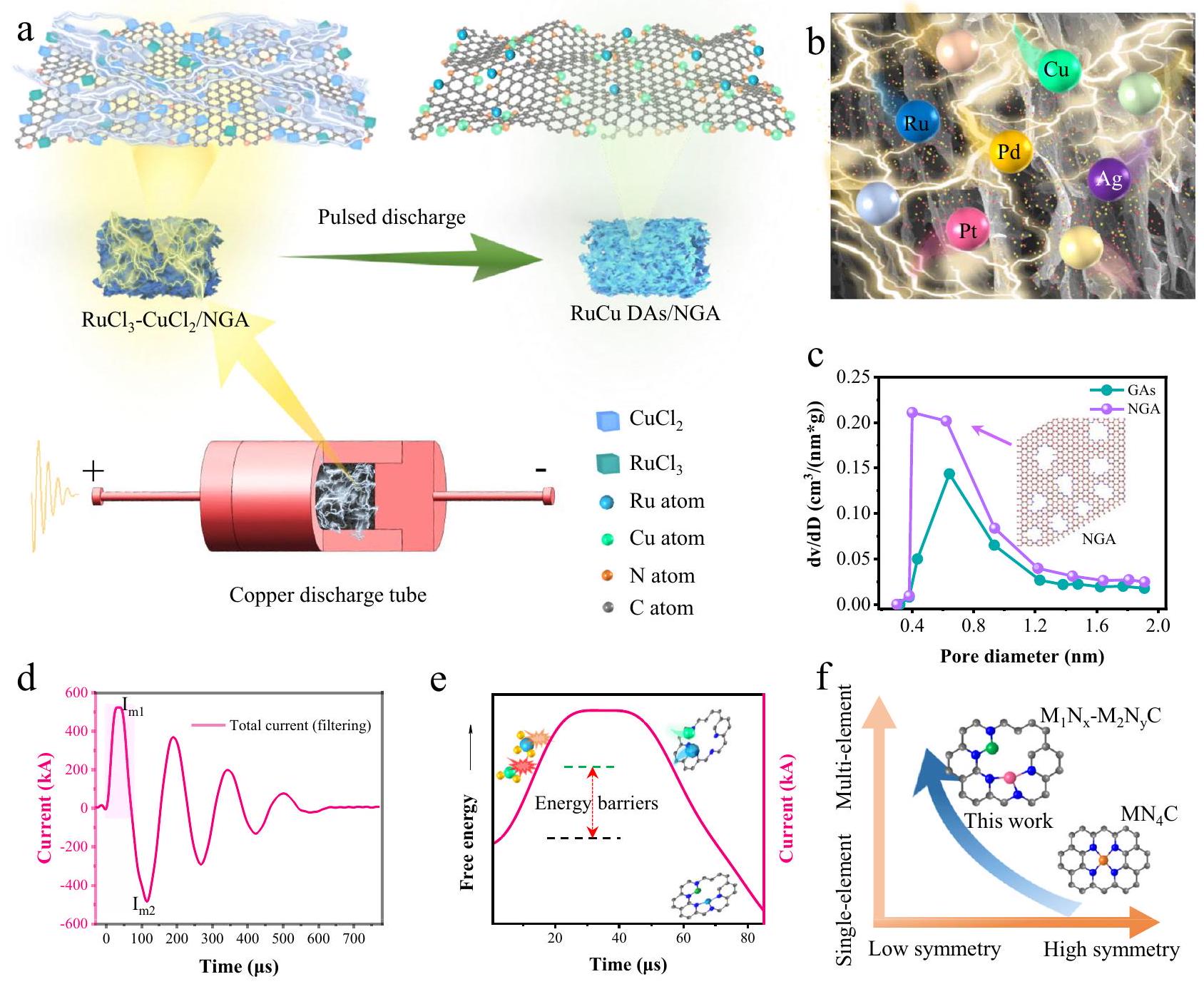
كعرض توضيحي، قمنا بتخصيص ذرات ثنائية من RuCu على ركائز NGA باستخدام استراتيجية التفريغ النبضي (الشكل 1أ). في البداية، تم تحضير هيدروجيل الجرافين المخصب بالنيتروجين (NGH) من خلال طريقة التجميع الهيدروحراري، ثم تم نقعه في المحاليل المائية لكلوريد النحاس. ) وكلوريد الروثينيوم ( ) لمدة 6 ساعات. NGA (الأشكال التكميلية 1، 2) دعمت و يمكن الحصول عليه من خلال طريقة تجفيف سريعة. تم تعبئة NGA في أنبوب تفريغ نحاسي وضغطه بواسطة سدادات نحاسية. تم توصيل طرفي الأنبوب النحاسي إلى القطبين الكهربائيين لنظام التفريغ النبضي عالي الطاقة من خلال شرائط نحاسية (الأشكال التكميلية 3، 4). بمجرد شحن المكثف بالكامل، سيتم تفعيل مفتاح الهواء في نظام التفريغ ليغلق بسرعة. نتيجة للتيار النبضي الضخم،أنتجت هي نفسها موجة صدمة حرارية فورية (درجة الحرارة تتجاوز 3000 كلفن على الجرافين أحادي الطبقة) وبلازما محلية على الجرافين أحادي الطبقة (الأشكال التكميلية 5-8). علاوة على ذلك، فإن تطبيق نبضة تيار عالية الكثافة يولد مجالًا كهرومغناطيسيًا قويًا، مما يؤدي إلى ظهور عدة مناطق عابرة ذات درجة حرارة مرتفعة على الجرافين.تنهار هياكل أملاح المعادن بشكل متفجر بسرعة بسبب إدخال طاقة هائلة، حتى مباشرة إلى أيونات *Ru و*Cu و*Cl الغازية من البلورات النانوية الصلبة (الشكل 1ب، الأشكال التكميلية 9، 10، الفيلم التكميلية 1). سيتسبب التفريغ النبضي المتكرر في تبخر الكتل النانوية المعدنية المتجمعة على الجرافين بشكل متكرر، مما يدفع ذرات المعادن لإعادة ترتيبها في الفضاء لتشكيل هيكل ثنائي الذرة، وهو مشابه لطريقة تسخين الجول.. يتم تثبيت هذه الذرات المعدنية الغازية بواسطة ذرات النيتروجين على الجرافين وتشكيل أزواج من الذرات المعدنية الثنائية تحت تأثير المجال الكهرومغناطيسي النبضي الحاد. يتم عرض توزيع المسام الدقيقة لـ NGA و الجرافين الهوائي (GAs) بواسطة تظهر اختبارات الامتصاص-الامتزاز في الشكل 1c، مع وجود ثقوب بأقطار تتراوح من 0.4 إلى 0.8 نانومتر كعيوب المسام الرئيسية على الجرافين المدعوم بالنيتروجين. الرسم التوضيحي (الشكل 1c) هو مخطط للجرافين المدعوم بالنيتروجين مع أنواع مختلفة من المسام الدقيقة، حيث توفر ذرات النيتروجين عددًا كبيرًا من المواقع لتثبيت الذرات المنصهرة الموزعة ذريًا. تعتبر هذه المسام الفرعية على الجرافين ثنائي الأبعاد الاستراتيجية الحرجة لتقييد الفضاء في تصميمنا لتثبيت أزواج الذرات المعدنية الثنائية. يمكن تحسين النشاط الظاهر للمواد الحفازة بسبب مساحتها السطحية العالية وبنيتها المسامية الدقيقة، مما يسهل انتقال الكتلة. يظهر الشكل 1d شكل الموجة الحالية النموذجية أثناء التفريغ النبضي. تم ضبط سعة الجهد عند 8 كيلو فولت، واقتربت القيمة من 0 بعد عدة تضعيفات متذبذبة، واستمرت لمدة إجمالية تبلغ حوالي . تأخر ذروة التيار الأولى عن ذروة الجهد الأولى بمقدار ، نتيجة للعمل المشترك للمكثفات والمحاثات في نظام التفريغ. يتم سرد المعلمات الرئيسية لذروة شكل الموجة الحالية في الجدول التكميلي 1 خلال عملية التفريغ النبضي. قدم التيار شكل موجة تحت التخميد النموذجي في هذه الدائرة المقاومة-المحث-المكثف (RLC)، مما يشير إلى أن المقاومة في الدائرة لم تتغير بشكل كبير خلال التفريغ النبضي. ستنفجر حواجز الطاقة لأملاح المعادن وتتفتت عندما يتم إدخال الطاقة العابرة، كما هو موضح في الشكل 1e. نظرًا لأن التيار وتأثير حرارة جول متزامنان تقريبًا ، فإن وقت ارتفاع درجة الحرارة من 0 إلى الذروة على بلورات الملح المعدنية النانوية يبلغ حوالي عشرات الميكروثواني. عندما يتم إدخال كمية كبيرة من الطاقة في فترة قصيرة على بلورات الملح المعدنية النانوية، فإنها ستتفكك بشكل متفجر وستثبت الأيونات المعدنية على NGA خلال التفريغ النبضي (ملاحظة تكملية). يؤثر تأثير الضغط المغناطيسي الناتج عن المجال الكهرومغناطيسي الديناميكي على توسيع الأيونات المتكونة شعاعيًا، مما يحافظ على البلازما ذات الكثافة العالية نسبيًا التي تحتوي على أيونات Ru و Cu على NGA. في الوقت نفسه، سيؤدي الهواء داخل هيكل NGA المسامي إلى ظهور بلازما تفريغ محلي تتكون من أيونات *O و *N.
خلال عملية التبريد، تتجمع بعض الذرات المعدنية القريبة معًا بشكل حتمي لتشكيل كتل نانوية معدنية (الشكل التكميلي 11). من الضروري تكرار معالجة التفريغ النبضي عدة مرات، حيث إنها تحفز تبخرًا متكررًا وتشتت الذرات المعدنية. يمكن أن تشكل ذرات Ru و Cu المختلطة أزواجًا ذرية على العيوب في NGA الناتجة عن تأثير الاحتجاز المدفوع بالديناميكا الحرارية. علاوة على ذلك، فإن التفريغ النبضي المتكرر يسهل الخلط الكامل لذرات المعادن Ru و Cu، مما يشكل أزواج ذرات Ru-Cu موزعة بشكل أكثر توازنًا على NGA بعد النقل المكاني وإعادة الترتيب. بعد عدة أحداث تفريغ، تسهل هذه الظروف تشكيل روابط قوية بين أزواج الذرات المعدنية
الشكل 1 | المخططات التوضيحية لتصنيع وتصميم RuCu DAs/NGA. أ رسم توضيحي استراتيجي لإعداد الاستراتيجية من خلال التفريغ النبضي. رسم توضيحي لذرات المعادن المحملة على NGA المسامي بواسطة التفريغ النبضي. ج توزيع المسام الدقيقة لـ NGA و GAs (الجرافين الهوائي)، الرسم التوضيحي هو مخطط للجرافين المدعوم بالنيتروجين مع أنواع مختلفة من المسام الدقيقة. د
منحنى التيار الكلي في الدائرة أثناء التفريغ. هـ رسم توضيحي يوضح عملية التكوين القصيرة لـ RuCu DAs/NGA مع تغيرات في إدخال الطاقة. اتجاه بحثي لمحفزات الذرات الفردية لزيادة تنوع العناصر المعدنية على الدعم وتشكيل هياكل تنسيق غير متماثلة. تم توفير بيانات المصدر للشكل 1 كملف بيانات مصدر.
وحامل NGA. نظرًا لأن قيمة ذروة التيار تُحتفظ فقط لعشرات الميكروثواني ثم تنخفض بسرعة إلى 0، يمكن الاحتفاظ بالهيكل الفريد للمعادن الموزعة ذريًا المدعوم من NGA بمعدلات تبريد عالية ووجود مستقر (الأشكال التكملية 12، 13). لقد أظهرت تجاربنا أن RuCu DAs/NGA يمكن الحصول عليها بالكامل بعد ست دورات من التفريغات النبضية.
اتجاه تطوير كبير في محفزات الذرات الفردية هو دمج عناصر معدنية متعددة على الدعم لتشكيل هياكل تنسيق غير متماثلة (الشكل 1f). باستخدام تأثيرات موجة الصدمة الحرارية السريعة وبلازما الكورونا الناتجة عن التفريغ النبضي، يمكن تصنيع محفزات موزعة ذريًا من معادن متعددة بسرعة. بالإضافة إلى ذلك، فإن خصائص التسخين والتبريد على نطاق الميكروثانية على الجرافين أحادي الطبقة تخلق ظروفًا مواتية لتشكيل ووجود مستقر للهياكل التنسيقية غير المتماثلة بين ذرات المعادن والدعم. مقارنةً بطرق التصنيع الأخرى للمحفزات الموزعة ذريًا، تبرز تقنية تصنيع التفريغ النبضي لدينا (الشكل التكميلي 14) بسبب درجات الحرارة الفورية العالية بشكل استثنائي ومدة قصيرة للغاية، على مستوى مئات الميكروثواني.
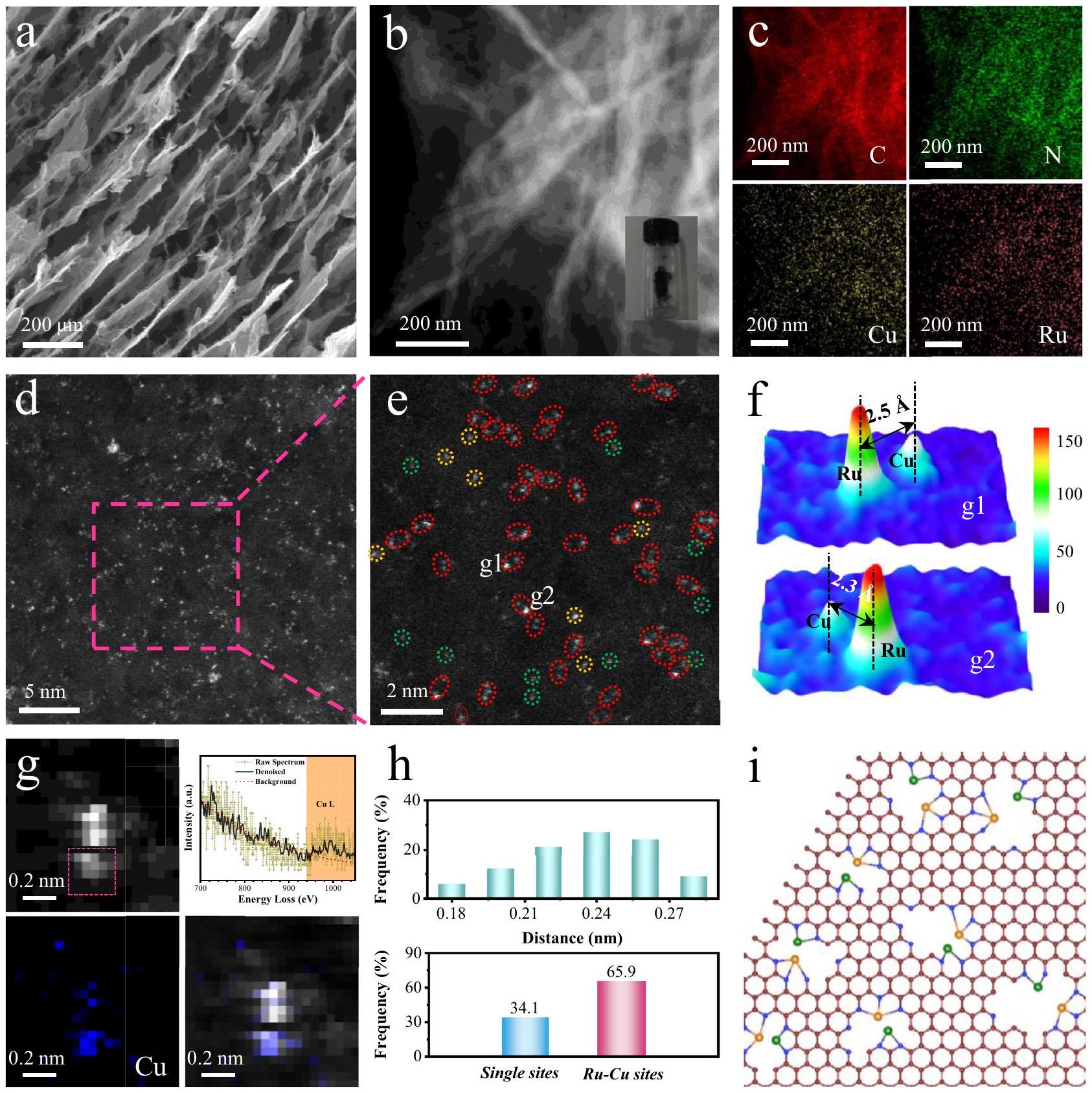
بعد ستة علاجات تفريغ نبضي، تم استرداد عينة RuCu DAs/NGA السليمة من أنبوب التفريغ. يعرض الشكل 2a صورة مجهر المسح الإلكتروني (SEM) لـ RuCu DAs/NGA، حيث تشبه الهياكل المسامية ثلاثية الأبعاد (عشرات الميكرونات) تلك الخاصة بـ NGA الأولية. لا تزال صورة مجهر الإلكترون الناقل (TEM) تعرض ميزات الجرافين المسامي المتجعد (عشرات النانومترات) (الشكل التكميلي 15). يظهر الشكل 2b صورة مجهر الإلكترون الناقل عالي الزاوية (HAADF-STEM) لـ RuCu DAs/NGA، حيث لم يتم العثور على جزيئات نانوية على الجرافين. يتم توضيح نتائج رسم خريطة الطيف الطاقي المقابل في الشكل 2c، حيث يتم توزيع العناصر C (أحمر)، N (أزرق)، Cu (أصفر)، و Ru (برتقالي-أحمر) بشكل موحد (الأشكال التكملية 16-18). تكشف صورة HAADF-STEM عالية الدقة عن عدد كبير من النقاط الساطعة الموزعة بشكل متساوٍ على الجرافين، كما هو موضح في الشكل 2d والأشكال التكملية 15g، 19. يُعتقد أن هذه النقاط الساطعة هي ذرات Ru و Cu الموزعة ذريًا لأن الأعداد الذرية للمعادن أعلى بكثير من تلك الخاصة بـ C و N وعناصر غير معدنية أخرى. الشكل 2 هـ هو صورة مكبرة جزئيًا من الشكل 2d، بسبب كون العدد الذري لـ Ru أكبر بكثير
الشكل 2 | خصائص RuCu DAs/NGA. أ صورة SEM لـ RuCu DAs/NGA. ب صورة HAADF-STEM لـ RuCu DAs/NGA. ج صور رسم خريطة EDS لـ RuCu DAs/NGA، C (أحمر)، N (أخضر)، Cu (أصفر)، و Ru (برتقالي أحمر). د صورة HAADF-STEM عالية التكبير (حقل مظلم). هـ الصورة المكبرة المحلية لـ RuCu DAs/NGA. ملفات تعريف الكثافة ثلاثية الأبعاد المقابلة على سبيل المثال نتائج خريطة EELS لزوج Ru-Cu في RuCu DAs/NGA، مع صورة HAADF-STEM في الزاوية العليا اليسرى، والطيف المقابل لمنطقة الصندوق في الزاوية العليا اليمنى، وخريطة Cu في الأسفل اليسار، و
صورة التراكب في الأسفل اليمين. تم دمج تصفية تمرير منخفض وتحليل المكونات الرئيسية لإزالة الضوضاء من بيانات EELS الخام. تم استخدام نطاق فقد الطاقة المميز لإنتاج خريطة Cu-L. تردد المسافة بين ذرات Cu و Ru المجاورة، وتردد المواقع الفردية ومواقع Ru-Cu المزدوجة. أنا رسم توضيحي لذرات زوج Ru-Cu بأنواع مختلفة مثبتة على الجرافين المدعوم بالنيتروجين. تم توفير بيانات المصدر للشكل 2 كملف بيانات مصدر.
من تلك الخاصة بـ Cu، فإن سطوع ذرات Ru في صورة STEM في الحقل المظلم أعلى بكثير من سطوع ذرات Cu. في الوقت نفسه، تشكل نسبة كبيرة من ذرات المعادن Ru-Cu أزواجًا. يوضح الشكل 2 و الصورة المقابلة لملفين ثلاثيي الأبعاد في الشكل 2e، والتي تعرض الفرق الواضح في الكثافة بين ذرات Ru و Cu، بالإضافة إلى الفرق الكبير مع C و N وذرات أخرى في NGA.
لتحديد الهياكل الثنائية المعدن بدقة أكبر، نقوم بإجراء تحليل طيف فقدان طاقة الإلكترون (EELS) للحصول على معلومات أكثر تفصيلاً حول التركيب العنصري والبيئة الكيميائية. بعد أن يتم إزالة الضوضاء بواسطة مزيج من التصفية المنخفضة من خلال التصفية وتحليل المكونات الرئيسية، كشف طيف EELS للذرة الداكنة بوضوح عن ميزة حافة Cu-L المميزة (الشكل 2g). ومع ذلك، من الصعب تحليل طيف EELS للذرة الأكثر سطوعًا، لأن الإشارة المميزة لحافة Ru-M تم التغلب عليها بواسطة إشارات حافة C-K وحافة N-K، مما حال دون حصولنا على بيانات EELS فعالة لذرة Ru.في صورة الطيف ذات الدقة الذرية (SI) HAADF لزوج ذرات Ru-Cu، يظهر تباين واضح بين الذرتين. تتطابق خريطة EELS للنحاس المستخرجة من نطاق فقدان الطاقة Cu-L المميز تمامًا مع ذرة النحاس في صورة SI-HAADF. نظرًا لعدم وجود عناصر معدنية أخرى يوجد على NGA بجانب Ru و Cu، أي ذرة معدن تُلاحظ بتباين أكثر سطوعًا من Cu في SI-HAADF بدقة ذرية يمكن أن تُعزى فقط إلى Ru. أكدت اختبارات EELS المتكررة (الأشكال التكميلية 20، 21) على جودة تكرار هذه النتيجة. علاوة على ذلك، يتم عرض توزيع تكرار المسافة الذرية المجاورة بين Ru و Cu وتوزيع تكرار المواقع الفردية والمزدوجة إحصائيًا في صور HAADF-STEM في الشكل 2h. المسافة المتوسطة بين ذرات Ru و Cu حوالي 0.25 نانومتر، ويتفاعل الاثنان بسهولة عند هذه المسافة. نسبة المواقع المزدوجة Ru-Cu حوالي، مما يشير إلى أن عينة RuCu DAs/NGA التي تم إعدادها بواسطة التفريغ النبضي تستحق هذا الاسم. ومن الجدير بالذكر أن العديد من ذرات النيتروجين توفر مواقع غنية لتثبيت ذرات المعادن. محتويات الروثينيوم والنحاس هي و على التوالي (الشكل التكميلي 15)، وهو ما يتماشى مع النتائج (رواختبار مطيافية الانبعاث الضوئي البلازمي المقترن بالحث (ICP-OES).
تم تحضير Cu SAs-DAs/NGA و Ru SAs-DAs/NGA (الأشكال التكميلية 22، 23) باستخدام نفس معلمات التفريغ النبضي ومصادر أملاح المعادن كما هو مستخدم في RuCu DAs/NGA. توجد نسبة من ذرات النحاس والروثينيوم كأزواج ذرية (أزواج النحاس: 43.8٪؛ أزواج الروثينيوم: 40.5٪) على Cu SAs-DAs/NGA و Ru SAs-DAs/NGA على التوالي. يمكن ملاحظة ميل لتجمع الروثينيوم والنحاس عندما تم تغيير الجهد إلى 9 كيلو فولت (الشكل التكميلية 24). وهذا يشير إلى أن إدخال طاقة أعلى يتسبب في انحراف أزواج الروثينيوم-النحاس عن مواقع التوازن الأصلية، مما يؤدي إلى تشكيل هياكل نانوية سبائكية على الجرافين المخصب بالنيتروجين. بالإضافة إلى ذلك، العينات ذات تم تحضير النسب (2:1 و 1:2) بواسطة تفريغ نبضي عند 8 كف. صور HAADF-STEM (الشكل التكميلية 25) لـ و يكشف أن تغيير الـنسبة أدت إلى تجمع الذرات أيضًا. تشير هذه النتائج إلى أن تخليق أزواج ثنائية الذرات من روثينيوم-نحاس موزعة بشكل موحد على NGA مناسب في الظروف الحالية.
تقدم الشكل 2i مخططًا تخطيطيًا لذرات ثنائية من Ru-Cu بأنواع مختلفة مثبتة على الجرافين المخدر بالنيتروجين، وهذه هي السبب الرئيسي للاختلاف في الأطوال بين ذرات Ru وCu. علاوة على ذلك، يمكن أن تؤثر الزوايا المتغيرة التي تتشكل بين RuCu وNGA على المسافات بين الذرات داخل أزواج ذرات Ru-Cu (الشكل التكميلي 26). نسبة الشدة لـإلىلـ RuCu DAs/NGA هو أعلى قليلاً من ذلك لـ NGA في اختبار رامان (الشكل التوضيحي 27)، مما يدل على أنه تم تشكيل المزيد من العيوب في الجرافين بسبب ذرات الدوبامين Ru-Cu أثناء التفريغ النبضي. تشير اختبارات الضغط إلى أن دوبينغ ذرات Ru وCu لم يعزز من قوة الضغط لدعم NGA، وقد يكون عملية التفريغ النبضي قد تسببت في بعض الأضرار لدعم NGA (الشكل التوضيحي 28). نمط حيود الأشعة السينية (XRD) (الشكل التوضيحي 29) يعرض فقط قمة واسعة مميزة واحدة عندنُسِب ذلك إلى طبقات الجرافين المكدسة. لا تظهر قمم لبلورات الروثينيوم أو النحاس في RuCu DAs/NGA. تُظهر نتائج XRD وRaman أن هيكل NGA في RuCu DAs/NGA لا يمكن تغييره بعد التفريغ النبضي.
تحليل هيكل الرابطة الذرية
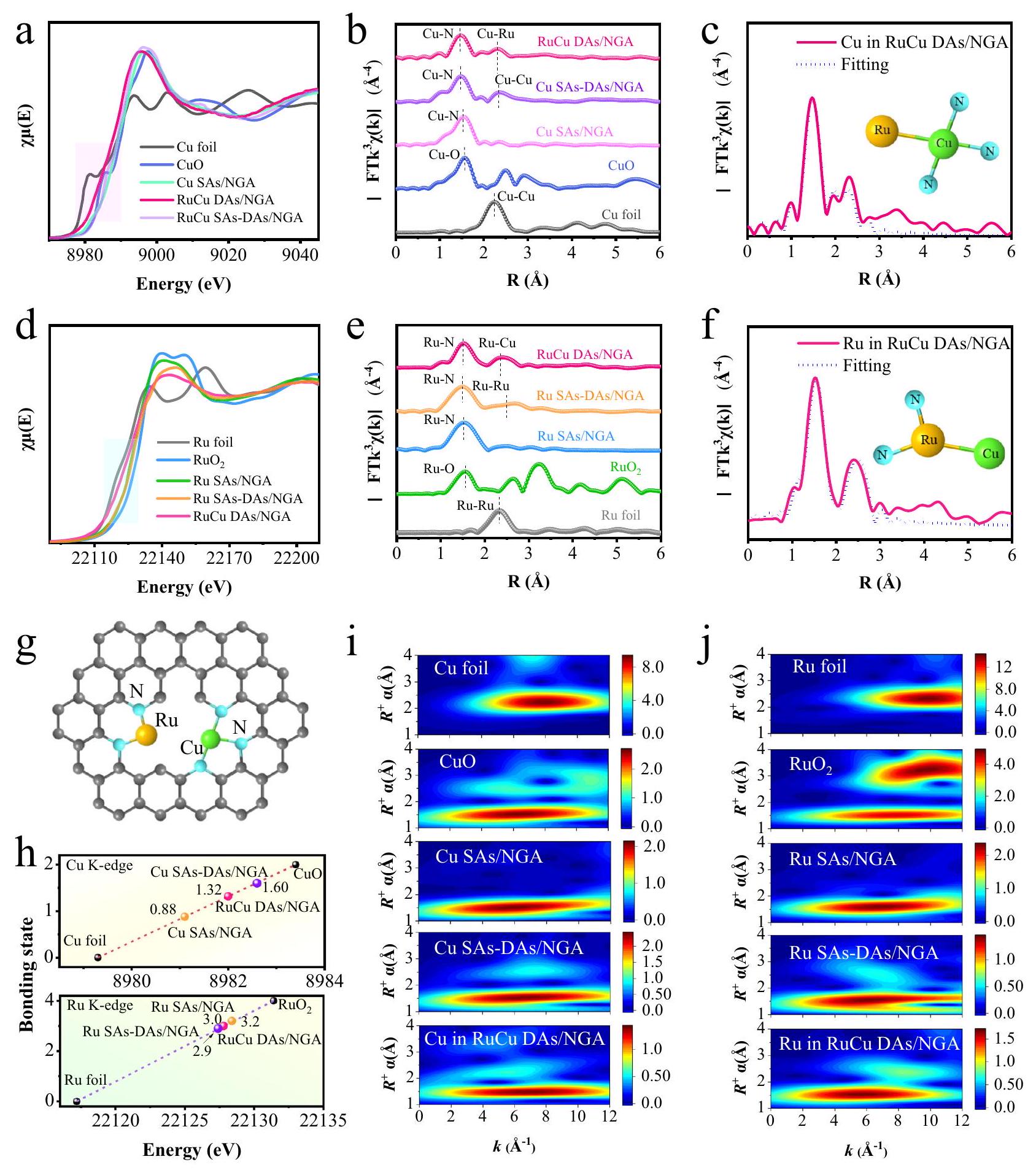
تمت دراسة بنية الرابطة الذرية لـ RuCu DAs/NGA باستخدام مطيافية الأشعة السينية للأشعة السطحية (XPS) وXAFS. تظهر طيف XPS لـ RuCu DAs/NGA في الشكل التكميلية 30، حيث تم تحديد قمة N1s مميزة، والتي تحتوي على رابطة C-N ورابطة ضعيفة C-Ru/Cu.الطيف له ذروتان عند 931.5 و 933.4 إلكترون فولت، على التوالي، مخصصتان لـو. بالإضافة إلى ذلك، تم الكشف عن الإشارات الضعيفة لـ Ru 3p أيضًا. تُعرض نتائج XAFS لـ RuCu DAs/NGA والمراجع في الشكل 3 والشكل التكميلي 31. يُظهر الشكل 3a طيف امتصاص الأشعة السينية بالقرب من حافة Cu K (XANES) لـ RuCu DAs/NGA والمراجع (Cu، CuO، Cu SAs/NGA، وCu SAs-DAs/NGA). حافة الامتصاص لـ RuCu DAs/NGA أقرب إلى تلك الخاصة بـ CuO مقارنةً بـ Cu foil، مما يشير إلى أن حالة الأكسدة لـ Cu في أقرب إلى CuO.فورييه الموزون تحويل (FT) من طيف الامتصاص بالأشعة السينية الممتدة عند حافة النحاس (Cu K-edge) (الشكل 3ب) يظهر أن قمم RuCu DAs/NGA و Cu SAs/NGA تقع عندالذي يُنسب إلىرابطة في تشتت القشرة الأولى. علاوة على ذلك، الذروة الثانوية عند من RuCu DAs/NGA قريب من موقع القشرة الأولى لرقاقة النحاس ( )، مما يعني وجود الهيكل التناسقي الثنائي الذرات المعدنية في RuCu DAs/NGA. تعرض الشكل 3c نتيجة تركيب EXAFS لحافة Cu K لـ RuCu DAs/NGA في فضاء R. تتطابق نتائج التركيب والنتائج التجريبية بدرجة عالية في مساحات مختلفة (فضاء R، فضاء k، وفضاء q، الشكل التكميلي 32). وبالمثل، تم استخراج المعلمات الهيكلية من نتائج تركيب EXAFS لحافة Cu K (الجدول التكميلي 2). تم تقدير عدد التنسيق لـ Cu ليكون 2.9 Cu-N (الذروة الأولى) و0.8 Cu-Ru (الذروة الثانية) في القشرة الأولى وفقًا لنتائج التركيب، مع أطوال روابط و “، على التوالي. يتم عرض XANES لحافة Ru K لـ RuCu DAs/NGA والمراجع (Ru، RuO2، Ru SAs/NGA، و Ru SAsDAs/NGA) في الشكل 3d. تقع حافة الامتصاص لـ RuCu DAs/NGA بينورو-الموزون FT من طيف EXAFS عند حافة Ru K (الشكل 3e) يظهر القمم القوية لـ RuCu DAs/NGA و Ru SAs/NGA تقع عند حوالي، التي تتوافق مع الروابط في القشرة الأولى. وبالمثل، فإن القمة الثانوية عند 2.36 Å من RuCu DAs/NGA قريبة من موضع قمة ورقة الروديوم ( )، مما يدل على وجود الرابطة المعدنية في RuCu DAs/NGA أيضًا. وبالمثل، تظهر نتيجة ملائمة جيدة في فضاء R كما هو موضح في الشكل 3f. استنادًا إلى نتائج الملائمة، فإن أعداد التنسيق لـ Ru-N و Ru-Cu هي 2.2 و 0.8 في القشرة الأولى على التوالي. أطوال الروابط لـ Ru-N و Ru-Cu هي و ، على التوالي. في النهاية، تم اقتراح هيكل تنسيق غير متماثل ( ) موضحة في الشكل 3g. وفقًا للمشتق الأول لحافة امتصاص النحاس (Cu) في RuCu DAs/NGA والمراجع، تم تقدير حالات التكافؤ للنحاس والروثينيوم (Ru) في RuCu DAs/NGA لتكون 1.32 و3.0، كما هو موضح في الشكل 3h. استنادًا إلى نتائج EELS (الشكل التكميلي 33) والمقارنة مع طيف النحاس القياسي لحالات التكافؤ المختلفة، فإن حالة التكافؤ لذرات النحاس المرتبطة بالروثينيوم تعادل على الأقل تلك الخاصة بذرات النحاس غير المرتبطة في RuCu DAs/NGA. على الرغم من القيود المفروضة بسبب نسبة الإشارة إلى الضوضاء المنخفضة وحجم العينة الصغيرة، لا يمكن أن تكون هذه النتيجة متوافقة تمامًا مع نتائج دراسات XAFS. ومع ذلك، لا تزال تدعم الاستنتاج بشأن تحليل حالة التكافؤ للنحاس المستمد من التوصيف الطيفي إلى حد ما. تم استخدام نتائج تحويل الموجات (WT) لحافة Cu وRu K-edge EXAFS في RuCu DAs/NGA والمراجع لتمييز الذرات المرتدة، كما هو موضح في الشكل 3i، j. موقع أقصى شدة للنحاس لـ هو الذي هو أقرب إلى ذلك منمن تلك الخاصة بورق النحاس. وبالمثل، فإن موقع أقصى شدة لرو (Ru) بالنسبة لـ RuCu DAs/NGAقريب من ذلك لـ. الفرق في الشدة بين RuCu DAs/NGA والمراجع ينشأ من المساهمة المشتركة لـ Ru-N، ، وRu-Cu.
استنادًا إلى تحليل نتائج XAFS لـ Cu SAs-DAs/NGA و Ru SAs-DAs/NGA، بالإضافة إلى هياكل الذرات الفردية من النحاس أو الروثينيوم، هناك كمية معينة من أو توجد هياكل أيضًا في كلا العينتين (الأشكال التكميلية 34، 35، الجدول التكميلية 3). هذه الملاحظة تتماشى مع النتائج التي تم الحصول عليها من تحليل HAADF-STEM. بالنسبة لعينات الكتل (، تشكل ذرات المعدن (النحاس والروثينيوم) هياكل تنسيق قوية مع ذرات النيتروجين على دعم NGA (الأشكال التكميلية 36-41). عدد التنسيق بين ذرات المعدن نفسها منخفض نسبيًا، مما يشير إلى أنه على الرغم من أن هذه المحفزات العنقودية ليست موزعة بشكل جيد على الدعم مثل المحفزات ذات الذرة المزدوجة، إلا أن عددًا كبيرًا من ذرات المعدن لا يزال مكشوفًا.
عمومية التخليق والتحليل الهيكلي لـ CuM DAs/NGA )
نظرًا لأن درجة الحرارة الفورية الناتجة عن التفريغ النبضي مرتفعة جدًا مقارنةً بدرجة حرارة التحلل الحراري لأملاح المعادن العادية، يمكن لهذه الطريقة أن تحضر بسرعة
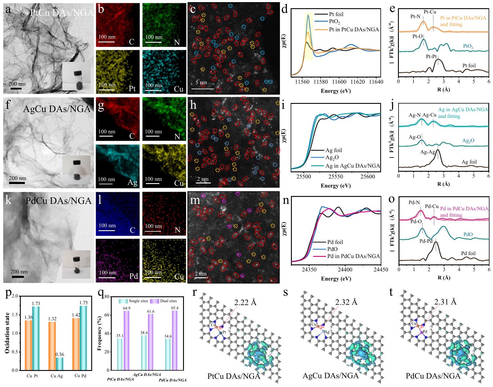
الشكل 3 | هيكل التنسيق الذري والحالة الكيميائية لـ RuCu DAs/NGA. أ طيف XANES عند حافة النحاس K لـ RuCu DAs/NGA والمراجع (رقائق النحاس، Cu SAs/NGA وCuO). ب تحويل فورييه عند حافة النحاس K-طيف EXAFS الموزون لـ RuCu DAs/NGA والمراجع. ج نتيجة تركيب EXAFS لحافة النحاس K لـ RuCu DAs/NGA في فضاء R. د طيف XANES لحافة الروثينيوم K لـ RuCu DAs/NGA والمراجع (رقائق الروثينيوم،، و ). حافة كاف Ru FT -طيف EXAFS الموزون لـ RuCu DAs/NGA والمراجع. ف نتيجة تركيب EXAFS لحافة Ru K لـ RuCu DAs/NGA في مساحة R.نموذج الهيكل الذري المقترح لـ RuCu DAs/NGA (الأصفر، Ru؛ الأخضر، Cu؛ السماوي، N؛ الرمادي، C). h حالات التكافؤ لـ Cu و Ru في RuCu DAs/NGA والمراجع بناءً على المشتق من الدرجة الأولى لطيف XANES. i نتائج WT-EXAFS لـ Cu في RuCu DAs/NGA والمراجع.نتائج WT-EXAFS للروثينيوم في RuCu DAs/NGA والمراجع. تم توفير بيانات المصدر للشكل 3 كملف بيانات مصدر. تشتت المستوى الذري لمعظم المعادن. بالإضافة إلى الهيكل ثنائي الذرات، تم تصميم تركيبات النحاس وعدد من المعادن الأخرى لتشكيل هياكل تنسيق غير متماثلة من NC على NGA في هذا البحث. يوفر الجمع بين النحاس والمعادن الأخرى المحفزات المزدوجة الموزعة ذريًا على NGA اختلافات تطبيقات محتملة لسيناريوهات الكهروكيميائية المختلفة. هنا، تم توسيع طريقة التخليق بالنبضات العامة بسهولة لتحضير ذرات ثنائية من معادن أخرى مدعومة بـ NGA، مثل PtCu DAs/NGA، وAgCu DAs/NGA، وPdCu DAs/NGA، إلخ. الشكل 4a يظهر صورة TEM لـ PtCu DAs/NGA، التي تعرض جرافين مطوي ثلاثي الأبعاد.
الشكل 4 | التوصيفات الهيكلية لـ MCu DAs/NGA الموسعة. أ صورة TEM لـ PtCu DAs/NGA. ب صور خرائط EDS لـ PtCu DAs/NGA، C (أحمر)، N (أخضر)، Pt (أصفر)، وCu (سماوي). ج صورة HAADF-STEM بتكبير عالي لـ PtCu DAs/NGA. د الـ Pt-طيف XANES عند الحافة لـ PtCu DAs/NGA والمراجع (رقاقة بلاتين) ). e -حافة-طيف EXAFS الموزون مع التوافق في فضاء R لـ PtCu DAs/NGA والمراجع.صورة TEM ل Ag-Cu DAs/NGA.صور رسم خرائط EDS لـ AgCu DAs/NGA، C (أحمر)، N (أخضر)، Ag (سماوي)، وCu (أصفر). h صورة HAADF-STEM بتكبير عالٍ لـ AgCu DAs/NGA. i طيف XANES عند حافة K لـ Ag لـ AgCu DAs/NGA والمراجع (رقائق Ag و ). -حافة FT-طيف EXAFS الموزون مع التوافق في فضاء R لـ AgCu DAs/NGA والمراجع. صورة TEM لـ PdCu DAs/NGA. I صور رسم خرائط EDS لـ PdCu DAs/
NGA، C (أزرق)، N (أحمر)، Pd (وردي) وCu (أصفر). m صورة HAADFSTEM بتكبير عالٍ لـ PdCu DAs/NGA. n طيف XANES عند حافة Pd K لـ PdCu DAs/NGA والمراجع (رقاقة Pd وPdO). o FT عند حافة Pd K-طيف EXAFS الموزون مع التوافق في فضاء R لـ PdCu DAs/NGA والمراجع.حالات الأكسدة للمعادن في PtCu DAs/NGA و AgCu DAs/NGA و PdCu DAs/NGA على التوالي. q تردد المواقع الفردية والمواقع المزدوجة (Pt و Ag و Pd). الهياكل المحسّنة وكثافات الشحن التفاضلية لـPtCu DAs/NGA، s AgCu DAs/NGA، وPdCu DAs/NGA (ألوان النموذج الذري: أزرق داكن، Pt؛ برتقالي، Cu؛ رمادي، Ag؛ بنفسجي، Pd؛ أزرق، N؛ رمادي، C؛ أبيض، H). تم توفير بيانات المصدر للشكل 4 كملف بيانات مصدر. خصائصه ولا يدعمه جزيئات أو تجمعات معدنية. بعد الغسل بالماء والتجفيف بالتجميد، فإن PtCu DAs/NGA هو هلام جرافين لاميلاري مكسور (انظر الشكل 4a). تُعرض صور رسم خرائط EDS لـ PtCu DAs/NGA في الشكل 4b، حيث يتم توزيع عناصر Pt وCu بشكل موحد على أوراق الجرافين المضافة بالنيتروجين. محتويات Pt وCu هي و ، على التوالي (الشكل التكميلية 42)، وهو ما يتماشى مع النتائج (Pt ) لاختبار ICP-OES. الشكل 4 ج يقدم صورة عالية التكبير بتقنية HAADF-STEM لزوج المعادن الثنائية PtCu DAs/NGA، مع الخط المنقط الأحمر الذي يحيط بمواقع زوج البلاتين والنحاس.
علاوة على ذلك، تم تحليل هيكل التنسيق لـ PtCu DAs/NGA من خلال اختبار XAFS. الـ Pt-نتائج XANES عند الحافة لـ PtCu DAs/ NGA والمراجع (رقاقة Pt و ) موضحة في الشكل 4d، حالة التكافؤ للبلاتين في PtCu DAs/NGA تتراوح بين 0 و +4 بناءً على شدة الخطوط البيضاء. تم حساب حالة التكافؤ للنحاس في PtCu DAs/NGA لتكون 1.36 (الشكل التوضيحي 43).-الموزون FT منطيف EXAFS عند حافة -edge (الشكل 4e) يظهر أن قمة PtCu DAs/NGA تقع عند، الذي يتوافق مع رابطة Pt-N في القشرة الأولى. بالإضافة إلى ذلك، فإن الذروة الثانية عندلـ PtCu DAs/NGA، يعادل القشرة الأولى من رقائق البلاتين )، مع اقتراح رابطة المعدن-المعدن. تم إدراج نتيجة ملاءمة EXAFS في فضاء R لـ PtCu DAs/NGA في الشكل 4e، ويمكن ملاحظة أن المنحنيات التجريبية ومنحنيات الملاءمة متوافقة. وبالمثل، يتم عرض الخصائص والهياكل لـ AgCu DAs/NGA و PdCu DAs/NGA في الشكل 4f-o والأشكال التكميلية 44-47. توفر الجدول التكميلية 4 أفضل معلمات هيكلية ملائمة، مما يشير إلى الهياكل التنسيقية المحلية لـ، و في العينات الثلاث. وفقًا للمشتق الأول لـحد الامتصاص (أو منطقة قمة الخط الأبيض لـ Pt) لـ PtCu DAs/NGA، AgCu DAs/NGA، PdCu DAs/NGA، ومراجعها، تُقدّر حالات أكسدة Cu لتكون 1.36، 1.32 و1.42 في PtCu DAs/NGA، AgCu DAs/NGA، وPdCu DAs/NGA على التوالي (الشكل 4p). حالات أكسدة، وتم حساب Pd في ثلاثة محفزات ليكونو 1.75 على التوالي. نسبة ، و المواقع المزدوجة هي، وعلى التوالي، مما يدل على أن المواقع المزدوجة التفاعلية للمعادن تهيمن مقارنة بالمواقع الفردية في PtCu DAs/NGA و AgCu DAs/NGA و PdCu DAs/NGA (الشكل 4q).
تظهر الهياكل المحسّنة وكثافات الشحن التفاضلية لـ PtCu DAs/NGA و AgCu DAs/NGA و PdCu DAs/NGA في الشكل 4r-s. أطوال الروابط لـ، و يُقدَّر أن الأزواج تكون، و على التوالي. علاوة على ذلك، فإن كثافات الشحن التفاضلية لـ، و تم حسابها لتوضيح الخصائص الكهربائية لمواقع CuM غير المتماثلة. الانتشار غير المتماثل لل…يؤدي إلى توزيع شحنة سطحية مستقطبة بشكل كبير. تراكم الإلكترونات (سماوي) بالقرب منموقع ونقص الإلكترون بالقرب منيمكن أن يُعزى ذلك إلى نقل الإلكترون منالموقع إلى، ، و المواقع، على التوالي (الشكل التكميلي 48). تُظهر الدراسات الثلاث الممتدة الاستراتيجية العالمية لتخليق هياكل الواجهة الذرية غير المتماثلة لطريقة التفريغ النبضي. يمكن أن تفتح هذه المجموعة من النحاس والمعادن النبيلة المزيد من الإمكانيات التحفيزية للمحفزات ثنائية الذرات الموزعة ذريًا. تم تصميم طريقة التفريغ النبضي بالفعل كاستراتيجية متعددة الاستخدامات لتحضير هياكل الواجهة الذرية غير المتماثلة من خلال الاستفادة من البيئة عالية الطاقة لتبخير سلف المعادن والألفة القوية لهيكل NGA لتثبيت واستقرار ذرات المعادن. استنادًا إلى تحقيقاتنا، فإن طريقة التفريغ النبضي ليست محدودة بأنظمة RuCu وPtCu وPdCu، بل يمكن أيضًا توسيعها لتشمل أنظمة أخرى قائمة على المعادن الانتقالية، مثل FeCu DAs/NGA وCoCu DAs/NGA وNiCu DAs/NGA (الأشكال التكملية 49-51). تؤكد النتائج، التي تم التحقق منها من خلال تحليل HAADF-STEM، على التكوين الناجح لهياكل ثنائية الذرات. وهذا يُظهر تعددية وعمومية نهجنا.
الكهروتحفيز والدراسة في الموقع
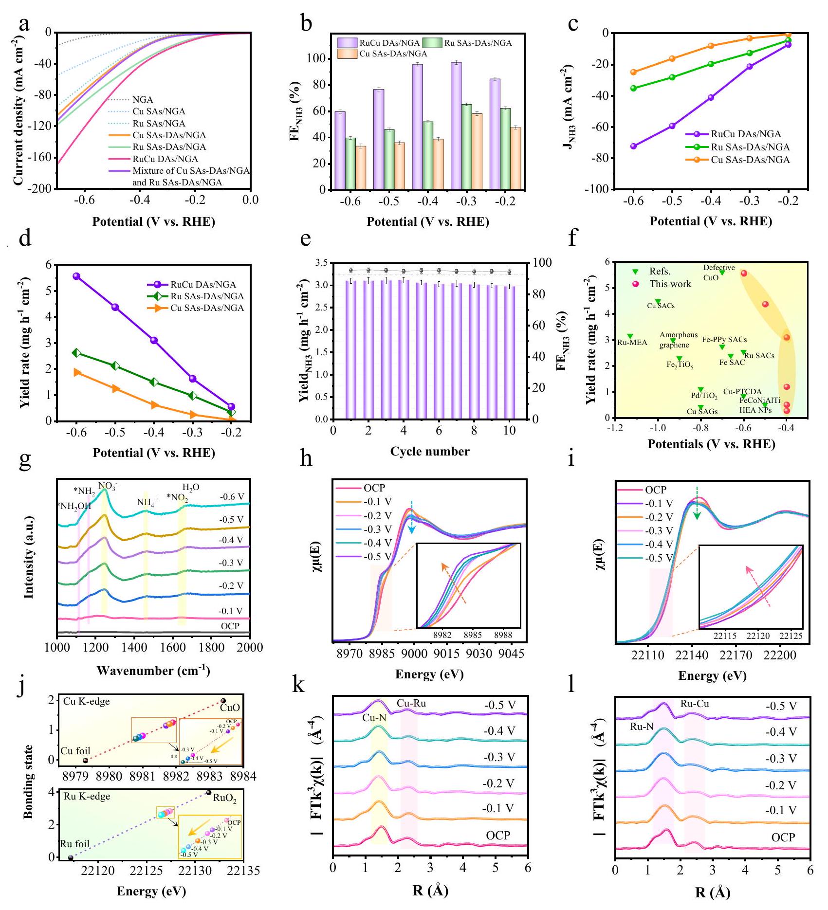
تم تقييم تفاعل اختزال النترات إلى الأمونيا في وظروف 0.1 م KOH، وتم عرض منحنيات الفولتمترية المسحية الخطية (LSV) في الشكل 5a. أظهرت RuCu DAs/NGA أقل جهد بدء وأسرع انخفاض في كثافة التيار بين المحفزات الثلاثة. تم دراسة الكفاءة فاراداي ومعدل تطور الأمونيا بواسطة الكرونوأمبيرومترية مع إمكانيات تشغيل مختلفة (الشكل التكميلي 52). يقدم الشكل 5b الكفاءة فاراداي لـ منتج عند إمكانيات مختلفة ( -0.1 فولت إلى -0.6 فولت مقابل RHE). بشكل مثير للإعجاب، من RuCu DAs/NGA وصلت عند -0.4 فولت مقابل RHE، فإن الأداء تنافسي للغاية مقارنةً بالمواد الحفازة الأخرى التي تم الإبلاغ عنها مؤخرًا (الجدول التكميلي 5). كثافة التيار الجزئي لـ على RuCu DAs/NGA الأداء الأمثل بين الثلاثة محفزات من -0.1 فولت إلى -0.6 فولت مقابل RHE (الشكل 5c)، مما يشير إلى التحسينالأداء من خلال التصميم غير المتناظر المخصصاستراتيجية هيكل التنسيق.وصلتعلى عند -0.3 فولت مقابل RHE. الـ تظهر نتائج معدل العائد (الشكل 5 د) أن RuCu DAs/NGA أكثر نشاطًا وانتقائية من المراجع.معدل العائد من RuCu DAs/NGA وصل إلى عند -0.4 فولت مقابل RHE، والذي لا يزال يقدم أداءً مثالياً مقارنةً بالعوامل المساعدة المماثلة في التقارير الحديثة (الشكل 5f، الجدول التكميلي 5). علاوة على ذلك، وصلت نسبة العائد من RuCu DAs/NGA إلى و عند -0.3 فولت و -0.5 فولت مقابل RHE على التوالي، وهو أفضل من المراجع (Ru SAs/NGA، Ru SAsDAs/NGA، Cu SAs/NGA، Cu SAs-DAs/NGA، RuCu Clu/NGA (9 kV)، ) وأفضل من المحفزات المماثلة أيضًا. تم تقييم مساهمة النشاط لمواقع الذرات الفردية ومواقع الذرات المزدوجة تحت ظروف تفاعل محكومة خلال . سيكون لدور المواقع الذرية الفردية في العملية الكهروكيميائية أهمية أكبر عند الجهود السلبية الأعلى (الأشكال التكميلية 53، 54). لكن مساهمات الـمعدل العائد أقل منللمواقع الفردية مقارنة بمواقع Ru-Cu المزدوجة عند إمكانيات تطبيق مختلفة.
تم قياس ECSA لكل عينة وتحليل بيانات النشاط التحفيزي وفقًا لذلك (الشكل التكميلي 55). بعد التطبيع كثافة التيار إلى المساحة السطحية الكهروكيميائية، من الواضح أن RuCu DAs/NGA لا يزال يظهر أعلى نشاط، يليه Ru SAs-DAs/NGA، بينما يظهر Cu SAs-DAs/NGA أقل نشاط (الشكل التكميلي 56). هذا يؤكد أكثر أن التأثير التآزري بين Ru وCu في RuCu DAs/NGA يمكن أن يعزز النشاط الكهروكيميائي.عملية. الطيف الرنين المغناطيسي النوويو (الشكل التوضيحي 57) يظهر قمم ثلاثية وزوجية مميزة عند انزياحات كيميائية تتراوح بين 6.8-7.0، بينما القمة عند حوالي 6.3 تت correspond إلى المعيار الداخلي.. هذه النتيجة تؤكد مباشرة أن في المنتج ينشأ من، بدلاً من الشوائب البيئية. لتحديد قدرة تحمل RuCu DAs/NGA تحت ظروف تم تنفيذ سلسلة من 10 دورات تحليل كهربائي مستمرة. توضح الشكل 5e أن RuCu DAs/NGA يظهر كفاءة فارادايك عالية مستدامة ومعدلات العائد عبر هذه الدورات، مما يثبت متانتها الاستثنائية. كانت خسارة الكثافة الحالية عند الجهد القابل للتشغيل الضئيل -0.4 فولت مقابل RHE خلال 24 ساعة من التشغيل المستمراختبار من (الشكل التوضيحي التكميلي 58). تظل الميزات المميزة لذرات الثنائي روديوم-نحاس بارزة، وتشير التحليلات الإحصائية إلى أن نسبة ذرات الثنائي روديوم-نحاس تبقى حوالي ، والتي قريبة من العينة الأصلية (الشكل التكميلي 59). استنادًا إلى نتائج XAFS (الأشكال التكملية 60، 61) لـ RuCu DAs/NGA بعد اختبار الاستقرار، يمكن ملاحظة أن هناك تغييرات طفيفة في الهياكل الإلكترونية لـ Ru و Cu. تكشف نتائج تركيب EXAFS أنه بعد اختبار الاستقرار، تظل بنية التنسيق للمحفز كما هي . هذا يشير إلى أنه بعد فترة طويلة من اختبارات لـفي الإنتاج، يحتفظ محفز RuCu DAs/NGA باستقراره الهيكلي.
قمنا باختبارالأداء عند تركيزات نترات مختلفة، الشكل التوضيحي التكميلي 62). أظهر كثافة التيار اعتمادًا واضحًا على تركيز النترات. وهذا يشير إلى أن RuCu DAs/NGA يظهر نشاطًا أعلى عند تركيزات نترات أعلى، مما يوحي بأن RuCu DAs/NGA هو محفز واعد لتفاعلات اختزال النترات الكهروكيميائية. في محلول KOH بتركيز 0.1 م بدون نترات، كان هناك تغيير طفيف فقط في كثافة التيار عند إمكانات مختلفة.. هذا يشير إلى أن RuCu DAs/NGA لا تسهل بشكل كبير عملية HER تحت هذه الظروف. تم إجراء اختبارات إضافية لتقييم الكفاءة فاراداي ومعدل الإنتاج لـلـ عند تركيزات نترات متفاوتة. كان من الواضح أن كلاً من الكفاءة فاراداي ومعدل الإنتاج كانت تعتمد بشكل كبير على تركيز النترات. أظهرت RuCu DAs/NGA كفاءة فاراداي أعلى ومعدل إنتاج لـ عند تركيزات نترات أعلى، مما يقضي على إمكانية حدوث تفاعل الهيدروجين (HER) تحت هذه الظروف. وهذا يبرز فعالية RuCu DAs/NGA كعامل حفاز لـ، مما يدل على تحسين الأداء مع زيادة توفر النترات. ويعزى ذلك إلى ميل أزواج الذرات RuCu لتفضيل، مما يؤدي إلى قمعها. انخفاض النشاط في و يمكن أن يُعزى ذلك إلى تجمع ذرات المعدن (الشكل التكميلي 63)، مما يقلل من عدد المواقع النشطة، وبالتالي يؤدي إلى ضعفأداء أفضل من العينة المعالجة بجهد 8 كف (RuCu DAs/NGA). وهذا يشير إلى أن زيادة تحميل المحفز، مما يؤدي إلى تجمع ذرات المعدن في نانو كتل، لا يعزز النشاط بشكل مباشر. بدلاً من ذلك، يمكن أن يؤدي تعريض المزيد من المواقع النشطة إلى تحسين الأداء التحفيزي. علاوة على ذلك، فإن زيادة محتوى الروثينيوم تحسن نشاط المحفزات بشكل أكبر من زيادة محتوى النحاس، مما يشير إلى أن ذرات الروثينيوم تلعب دورًا أكثر أهمية في التحفيز الكهربائي..
لتوضيح المزيد من الوسطاء المعنيين فيتم إجراء قياسات ATR-SEIRAS في الموقع على مختلف المحفزات الكهربائية (الشكل التوضيحي التكميلي 64). يقدم الشكل 5g النتائج لـ عند جهد الدائرة المفتوحة (OCP) ، ، و -0.6 فولت مقابل RHE. زيادة تدريجية في الشدة
شكل.أداء ونتائج في الموقع لـ RuCu DAs/NGA. منحنيات LSV لـ RuCu DAs/NGA، Ru SAs-DAs/NGA، Cu SAs-DAs/NGA، مزيج Ru SAs-DAs/NGA وCu SAs-DAs/NGA، Ru SAs/NGA، Cu SAs/NGA، وNGA المقاسة في 0.1 M و 0.1 م من إلكتروليت KOH. ب إن FEs لـ الإنتاج عند إمكانيات تطبيقية مختلفة لـ RuCu DAs/NGA و Ru SAs-DAs/NGA و Cu SAs-DAs/NGA. ج كثافات التيار الجزئي لـ NH3 لثلاثة محفزات عند إمكانيات مختلفة. د معدل العائد المعتمد على الإمكانية لـجيل فوق RuCu DAs/NGA. اختبارات الدورات لـ RuCu DAs/NGA من أجل عند -0.4 فولت مقابل RHE. ف مقارنة بـ معدل العائد والإمكانات لـ RuCu DAs/NGA ومختلف المحفزات التي تم الإبلاغ عنها مؤخرًا (انظر التفاصيل في الملحق)
الجدول 6طيف ATR-SEIRAS المعتمد على الجهد في الموقع (1000-2000 سم ) خلال العملية الكهروكيميائية عملية. و طيف XANES لحافة رو (Ru K-edge) لمركبات روكوب (RuCu DAs/NGA) عند إمكانيات تطبيقية مختلفة (OCP،، و -0.5 فولت ) خلال عملية.حالات التكافؤ للنحاس والروثينيوم في RuCu DAs/NGA والمراجع المستندة إلى المشتق من الدرجة الأولى لطيف XANES. و حد Ru K-وزن FT-EXAFS عند إمكانيات مختلفة خلالالعملية. لم يتم استغلال جميع الإمكانيات-تم التصحيح. تم توفير بيانات المصدر للشكل 5 كملف بيانات المصدر. مننطاق الاهتزاز عندتمت ملاحظته من OCP إلى -0.6 فولت، مما يدل على الاستهلاك المستمر لـأثناء التحليل الكهربائي. قمة عريضة مركزة حول (الشكل التوضيحي التكميلي 65)، تم التعرف عليه على أنه * الأنواع، تم ملاحظتها باستمرار. بالإضافة إلى ذلك، فإن ذروات كثافات الوسائط الهيدروجينية (* فيفي ) ، فيو intermediates إزالة الأكسدة (في ) زادت تدريجياً . تشير هذه النتائج إلى أن محفز RuCu DAs/NGA فعال للغاية في تنشيط، مما يسهل بعد ذلك تشكيل كميات كبيرة من وسائط الهدرجة التي في النهاية يتم تحويلها إلى. الكشف عن * و تشير الأنواع إلى حدوث كل من مسارات التخفيض غير المباشر والمباشر خلالعملية على NGA. بالإضافة إلى ذلك، هناك تحسين كبير في اهتزازات تمدد H-O-H عند حوالي و تمت ملاحظته، مما يدل على تفككإلىوالأنواع، التي تم تثبيتها على محفز RuCu DAs/NGA.
لدراسة علاقة التركيب بالنشاط لمركبات RuCu DAs/NGA على المستوى الذري، تم إجراء اختبارات XAFS في الموقع خلال التحفيز الكهروكيميائي.العملية. الشكل 5 ح، ط يقدم نتائج XANES عند حافة Cu K وحافة Ru K لـ RuCu DAs/NGA عند OCP، -0.1 فولت،، و -0.5 فولت مقابل RHE. تميل حواف الامتصاص لكل من النحاس والروثينيوم في RuCu DAs/NGA إلى التحرك تدريجياً نحو طاقة أقل، مع انخفاض شدة خطوطهم البيضاء، مما يدل على انخفاض حالات الفالنسية للنحاس والروثينيوم مع انخفاض الجهود المطبقة. وفقًا للنتائج (الشكل التكميلي 66) للمشتق الأول لحافة الامتصاص لـ RuCu DAs/NGA، انخفضت حالات الفالنسية المحددة للنحاس من 1.27 إلى 0.73 عندما تم تقليل الجهود المطبقة. وبالمثل، انخفضت حالات الفالنسية للروثينيوم من 2.87 إلى 2.62 بشكل مستمر (الشكل 5j). في الواقع، يكشف النحاس والروثينيوم عن اتجاهات مماثلة في حالات الأكسدة بسبب يتم امتصاصه على الموقع النشط للمحفز في الإلكتروليت، مما يؤدي إلى التفاعل على السطح الخارجي غير المتزاوج.مدارات النحاس والروثينيوم معمداراتستستمر حالات الأكسدة لكل من النحاس والروثينيوم في الانخفاض عند تطبيق إمكانيات تفاعل أقل. ستتفاعل المواقع النشطة المزدوجة للنحاس والروثينيوم مع المواد الماصة.أسهل في التشكيل الروابط عند إمكانيات أقل، مما يؤدي إلى إعادة توزيع الإلكترونات بين “، وذرات الأكسجين. تظهر طيف FT-EXAFS عند حافة Cu K (الشكل 5k) لـ RuCu DAs/NGA أن قمة Cu-N تنتقل منإلىالذي اعتُبر كضغط لـ الروابط. تظهر طيف FT-EXAFS عند حافة Ru K (الشكل 51) لـ RuCu DAs/NGA أن قمة Ru-N تنتقل من (OCP) إلى مع انكماش الروابط أيضًا. بالإضافة إلى ذلك، تميل روابط الروثينيوم والنحاس أيضًا إلى الانتقال إلى اليسار خلال العملية. نظرًا لأن ذرات المعدن من المحتمل ألا تكون في نفس المستوى مع الجرافين، فمن الممكن أن تكون هناك روابط معدنية وروابط معدنية-ن مثبتة. بالإضافة إلى ذلك، تميل روابط الروثينيوم-النحاس أيضًا إلى التحرك قليلاً إلى اليسار خلالالعملية. تحليل أطوال الروابط المذكورة أعلاه يتماشى مع نتائج التوافق المحددة (الأشكال التكميلية 67، 68، والجدول التكميلية 6). نظرًا لأن ذرات المعدن من المحتمل ألا تكون على نفس المستوى مع الجرافين، فمن الممكن أن تكون مضغوطة لكل من روابط Ru-Cu وروابط Cu/Ru-N. باختصار، الأداء العالي لمركبات RuCu DAs/NGA في التحفيز الكهربائي RR ناتج عن التأثير المشترك لـأجزاء التنسيق. خلالخلال العملية، تغيرت الهيكلية التنسيقية المحلية (عدد التنسيق وطول الرابطة، إلخ) بالقرب من مواقع Ru-Cu قليلاً، وسيتم تشكيل هيكل جديد مستقر. قد يكون اكتشاف الوسائط التفاعلية الممتصة بواسطة مواقع Ru-Cu النشطة هو السبب الرئيسي.
دراسة نظرية لـ
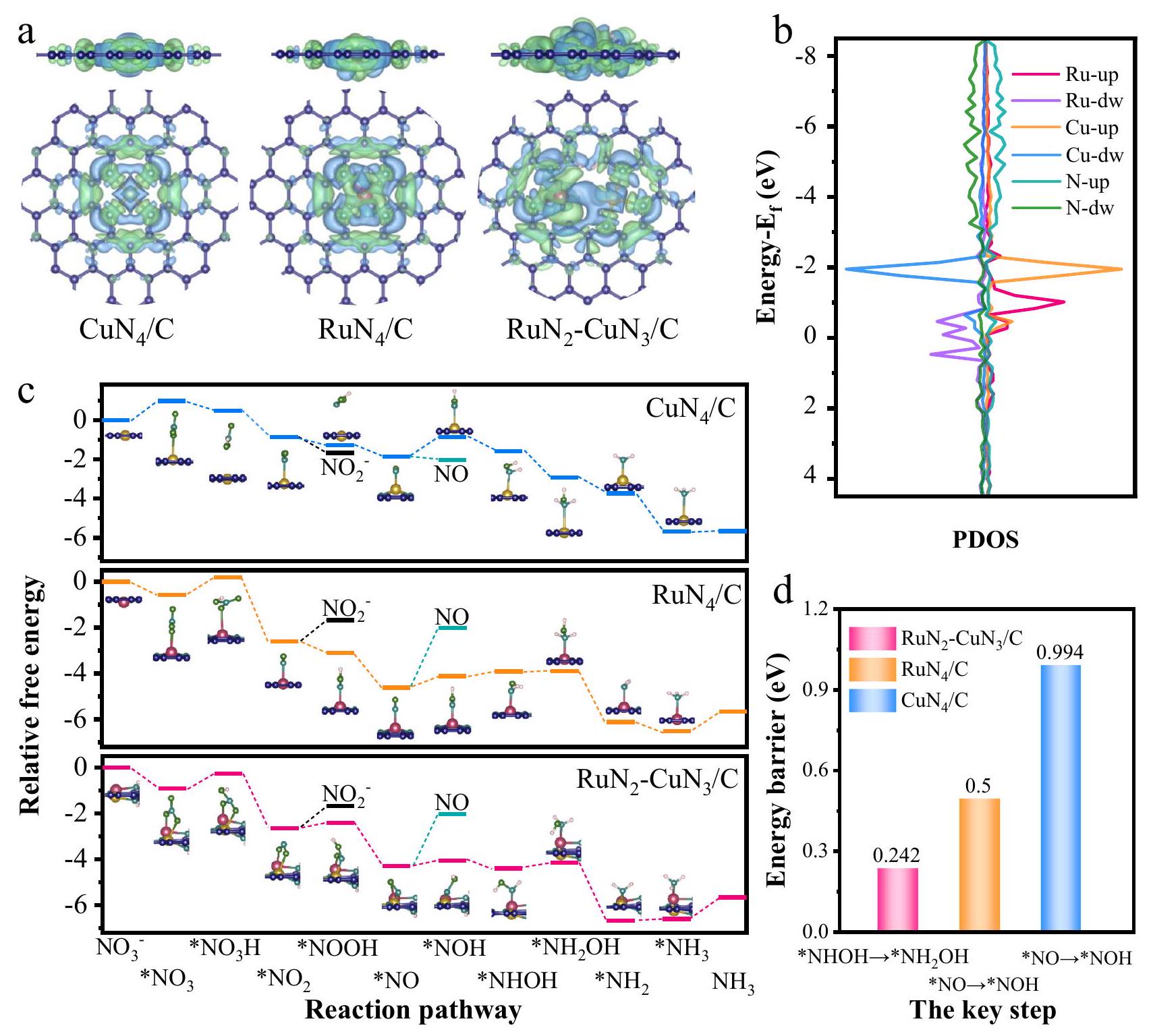
لفهم الآلية الأساسية لـالمنتج مخفض منبالنسبة لـ RuCu DAs/NGA، تم استخدام طريقة DFT للتحقيق في العملية بأكملها لـعلى غير المتناظرالأجزاء (البيانات التكميلية 1). كثافات الشحن التفاضلية (الشكل 6أ) لـ، و تم حسابها لتوضيح الخصائص الكهربائية لمواقع الروثينيوم والنحاس ولدراسة التفاعلات التآزرية لذرتي المعدن غير المتناظرتين أيضًا. RuNالموقع يجعل من الأسهل الحصول على الإلكترونات (منطقة غنية بالإلكترونات، المنطقة الخضراء) منالموقع، مما يدل على قدرة تقليل أقوى. لذلك، يمكن التنبؤ بأنسيكون له قدرة امتصاص أقوى لل intermediates منمن خلال النشر غير المتناظر للمعدليبدو أن توزيع الشحنة السطحية مت polarized بشكل ملحوظ. زيادة الإلكترونات بالقرب منونقص الإلكترونات بالقرب منيمكن أن تُنسب إلى نقل الإلكترون من موقع النحاس إلى موقع الروثينيوم. إلى كشف السبب الكامن وراء التفاعلات بينالمواقع والأنواع التفاعلية، الكثافات المتوقعة للحالة (PDOS) لـ، و التركيز علىتم محاكاة المدارات الخاصة بالروثينيوم والنحاس (الشكل التكميلي 69 والشكل 6b). وفقًا لـنظرية مركز النطاق، الـمدارات النحاس فيأبعد من مستوى فيرمي مقارنةً بالروثينيوم فيامتصاص الوسائط علىأضعف من ذلك علىالمعدلله تأثير تآزري قوي،مدار الروديوم أقرب إلى مستوى فيرمي، وله تأثير امتصاص أقوى للوسطاء التفاعليين، مما يؤدي إلى نشاط تحفيزي أعلى على. علاوة على ذلك، آخر الموقع الذي يمتلك قدرة امتصاص ضعيفة قليلاً قد يعزز من عملية إزالة الوسطيات، مما يساعد على زيادة معدل التفاعل.
كلالمسارات والطاقة الحرة النسبية على، و فيمقابل RHE موضحة في الشكل 6c والأشكال التكميلية 70-72.يتم امتصاصه أولاً ويتم تفريغه على المواقع المعدنية، مكونًا *“، ثم تحولت إلى *. بعد ذلك، * يتحول إلى *مع مغادرة الـ. بعد ذلك، كما أن البروتونات فيتستمر في الإضافة إلى الوسطى وسحب ذرات الأكسجين (تشكيل)، يتشكل تدريجياً. أخيراً،يتم امتصاصه لإنتاجترك مواقع المعادن. عملية تطور الوسائط منإلىالمنتج علىالهيكل هو: * * * . الستة وسطاء الأوائل ( ، *نوح، *لا، وNOH) يتم امتصاصها معًا بواسطة Ru و Cu، وهذه التهيئة المحسّنة تقلل من حاجز الطاقة للتفاعل. بعد ذلك، يتم الحصول على الوسائط ( NHOH و ) يتم امتصاصها بواسطة ذرة روديوم مفردة. ذرة النيتروجين من يتم امتصاصه بواسطة ذرات الروثينيوم والنحاس. أخيرًا، يمتصه ذرة الروثينيوم الفردية. تشير هذه الخطوات إلى أن ذرة الروثينيوم تلعب دورًا أكثر أهمية فيالهيكل أثناء التحفيز الكهربائيتتعاون ذرات الروثينيوم والنحاس لتقليل *إلى * NO في المراحل المبكرة من التفاعل. إنه بشكل رئيسي ذرة الروثينيوم التي تقلل *NO إلى *في المراحل اللاحقة من التفاعل. يمكن أن يقلل التأثير التآزري بين ذرات الروثينيوم والنحاس من طاقة التفاعل الحرة ويعمل على تحسين امتصاص وفك امتصاص الوسائط، مما يسهلعملية.
تم عرض مسار التفاعل الكامل والطاقة الحرة النسبية لكل خطوة في الجدول التكميلية 7.يمكن تقسيم خطوات التفاعل إلى جزئين، وهما عملية امتصاص/إطلاق المتفاعلات أو المنتجات (تفاعل غير مرتبط بكسب/فقدان الإلكترونات) وخطوات تفاعل كسب/فقدان الإلكترونات.إلى *“، نظرًا لأن عدد نقل الشحنة هو 0، يمكن اعتبار العملية كإعلانات للمنتج بواسطة مواقع المعدن. وفقًا لموقع الطاقة لـ *، امتصاص *بواسطة هو الأقوى، يليه و هو الأسوأ. سيتجمع كمية كبيرة من المتفاعلات فيالموقع النشط، وزيادة تركيز المتفاعلات مفيدة للتفاعل. منإلى، فإن الوسطاء في التفاعل الأساسي سيحصلون على في كل خطوة. بالنسبة للتفاعل الأساسي لاكتساب أو فقدان الإلكترونات، كلما كانت حاجز الطاقة أصغر، كانت التفاعل أسهل.، و الحاجز الطاقي الأقصى المقابل هو 0.252 إلكترون فولت (*NHOH، و في خطوات اكتساب/فقدان الإلكترون الخاصة بهم (الشكل 6د). لاحظ أن حاجز الطاقة لـ *NO * NOH على هو 0.242 إلكترون فولت. بالمقارنة مع يقلل من حاجز الطاقة للخطوة الرئيسية لـ *NOبينما يتم تقليل حاجز الطاقة لهذه الخطوة بشكل أكبر في هيكل الذرات المزدوجة Ru-Cu. وبالتالي، لم يعد *NO → *NOH هو الخطوة الرئيسية في تحديد معدل التفاعل على، بينما * هي الخطوة الحاسمة. المركب الوسيط الأكثر حيوية هو *NO في، وتقليل حاجز الطاقة لخطوة الهدرجة هو المفتاح لعمل هذه المحفزات. التماثل غير المتناظرتظهر البنية أفضل تأثير في المحفزات الثلاثة. استنادًا إلى مواقع الطاقة الحرة النسبية لـ *NO و *NOH، فإن امتصاص موقع النحاس للوسائط ضعيف جدًا، ويمكن لموقع الروثينيوم تعزيز امتصاص هذه الوسائط، ولكن امتصاص *NO قوي جدًا وقد لا يكون
الشكل 6 | نظريتحليل النشاط على RuCu DAs/NGA. أ الكثافات الشحنية التفاضلية لـ، و الكثافة المتوقعة للحالات من. ج الكهروكيميائيةالمسارات والطاقة الحرة النسبية على، و في مقابل RHE. د حواجز الطاقة لـ خطوات رئيسية في، و لون نموذج الذرة: أحمر، روديوم؛ أصفر، نحاس؛ أخضر، أكسجين؛ سماوي، نيتروجين؛ أزرق، كربون؛ وردي فاتح، هيدروجين. تم توفير بيانات المصدر للشكل 6 كملف بيانات مصدر. مساعد على التفاعل. في الـ الهيكل، يحافظ الروديوم على الامتصاص القوي لـ *NOH، لكنه يضعف امتصاص *NO، لذا يتم تقليل حاجز الطاقة لهذه الخطوة. من كثافة الشحنة التفاضلية للوسائط الرئيسية (*NO، الشكل التوضيحي 73)، يحصل *NO على شحنة أكبر في النظام المحتوي على الروديوم. الفرق الرئيسي بين أنظمة الروديوم-النحاس وأنظمة الروديوم الفردية هو تكوين الامتصاص، حيث يتم امتصاص NO بشكل أفقي، ويتعاون الروديوم-النحاس معًا في نظام.
لStep الأخيرهو عملية إزالة الامتصاص للمنتج، حيث يكون امتصاص الوسيط عند موقع النحاس ضعيفًا، مما يجعل المنتج أسهل في الإزالة. قدرة الإزالة في النظام المحتوي على الروثينيوم أكبر قليلاً، لكنها لا تزال أقل من 1 إلكترون فولت، مما يمكن أن يتم عند درجة حرارة الغرفة. ). الخطوة الأخيرة ليست حاسمة ما لم يكن الإزالة كبيرة تصل إلى تسميم المواقع المعدنية، حيث لم تصل الحواجز بعد إلى الظروف اللازمة للتسمم. تحت ظروف التفاعل الفعلية، المنتج يذوب بشكل كبير في الماء، وطاقة الإزالة التي تقل عن 1 إلكترون فولت لن تلوث الموقع المعدني. بالإضافة إلى ذلك، فإن النظام الذي يحتوي على الروثينيوم لديه انتقائية عالية لـ مسار، تقريبًا فقط على طول مسار الإنتاج. بينما قد ينتجولا (حاجز طاقة منخفض)الانتقائية ليست عالية بما فيه الكفاية. هذا يتماشى معنتائج الاختبار.
نقاش
في الختام، قمنا بتصميم ذرات ثنائية المعدن بنجاح باستخدام عيوب المسام النانوية على NGA وقمنا بتخليق محفزات ثنائية الذرات من RuCu موزعة ذريًا (RuCu DAs/NGA) بسرعة من خلال طريقة التفريغ النبضي. تشير تحليلاتنا الارتباطية إلى هيكل تنسيق غير متماثل لـعلى NGA لـ RuCu DAs/NGA. من الجدير بالذكر أن تقنية التفريغ النبضي هذه يمكن تكييفها لتحضير مجموعة متنوعة من المحفزات ثنائية الذرات بكفاءة، بما في ذلك PtCu وAgCu وPdCu DAs/NGA. يظهر محفز RuCu DAs/NGA نشاطًا كهربائيًا ملحوظًا وانتقائية لإنتاج الأمونيا عبرتظهر كل من التحقيقات التجريبية والحسابات النظرية أن التصميم غير المتناظر المخصصالبنية تعزز التعاون القوي، مما يحسن وينظم كل تفاعل أساسي بشكل فعال. تمتد تداعيات هذا البحث تتجاوز الاهتمام الأكاديمي؛ إن قابلية التوسع والتطبيقات العملية لمحفزات RuCu DAs/NGA لدينا مهمة من أجل الاستدامةالإنتاج من خلالالتقليل. إن القدرة على إعداد المحفزات ثنائية المعدن بسرعة مع هياكل محسّنة لا تعزز فقط الأداء التحفيزي ولكنها تحمل أيضًا وعدًا للتطبيقات الصناعية حيث تكون العمليات فعالة ومستدامة. نحن نتخيل أن استراتيجية التفريغ النبضي يمكن أن تسهل تطوير المحفزات المتقدمة القابلة للتطبيق في سيناريوهات تحويل الطاقة والتحفيز المختلفة، مما يساهم في الجهود المستمرة في الكيمياء المستدامة وإصلاح البيئة.
تم تحضير أكسيد الجرافين أحادي الطبقة (GO) بواسطة طريقة هومرز المعدلة. أكسيد الجرافين (30 ملغ) وتم dispersingها بالكامل في الماء المنزوع الأيوناتتم صب الخليط المتوزع بشكل متساوٍ في مفاعل هيدروحراري صغيرمسخن إلىوتم الاحتفاظ بها هناك لمدة 6 ساعات. بعد التبريد إلى درجة حرارة الغرفةتم تشكيل NGH. بعد تنظيف NGA عدة مرات بالماء المقطر، تم غمره في محلول مائي من كلوريد النحاس والروثينيوم (Cu و ) لمدة 3 ساعات. مدعوم من NGA و نانوكريستالاتتم الحصول عليها بعد التجميد السريع باستخدام النيتروجين السائل والتجفيف بالتجميد. تم إعدادتم ملؤه في أنبوب تفريغ نحاسي باستخدام سدادتين نحاسيتين ملولبتين لتثبيت الأطراف (فيلم إضافي 2). ثم أنبوب التفريغ الذي يحتوي علىتم توصيله على التوالي بدائرة نظام التفريغ النبضي عالي الطاقة. تم ضبط جهد الشحن على 8 كيلو فولت، وتم تفعيل المفتاح الهوائي تلقائيًا بعد انتهاء شحن المكثف. ستمر تيارات النبض عبر أنبوب التفريغ النحاسي و، و سيتم تحويله بالكامل إلى RuCu DAs/NGA بعد ست عمليات معالجة بتفريغ نبضي متكرر. كانت عملية تحضير PtCu DAs/NGA و AgCu DAs/NGA و PdCu DAs/NGA و FeCu DAs/NGA و CoCu DAs/NGA و NiCu DAs/NGA مشابهة لتلك الخاصة بـ RuCu DAs/NGA. يتم تقديم خصائص التفريغ النبضي في الملاحظات التكميلية. تم نقع NGH في محلول إيثانول من أسيتيل أسيتون النحاس.، أو لمدة ساعتين، تم غسلها بالماء المقطر، وتجفيفها بالتجميد للحصول على جرافين مدعوم بالنحاس أسيتيل أسيتون.يتم وضعه في فرن أنبوبي ويتم تحلل حراري في جو من النيتروجين لمدة ساعتين عند درجة حرارة تسخينللحصول على Cu SAs/NGA و Ru SAs/NGA. بالإضافة إلى ذلك، Cu SAsDAs/NGA و Ru SAs-DAs/NGA،، و تم تحضيرها بواسطة تفريغ نبضي عند 8 كيلوفولت، وتم تغيير أملاح المعادن فقط مقارنةً بـ RuCu DAs/NGA. تم تحضير RuCu Clu/NGA (9 كيلوفولت) بواسطة تفريغ نبضي عند 9 كيلوفولت.
توصيفات
تم فحص الميكروهيكل للمواد المُركبة بواسطة مجهر المسح الإلكتروني ذو الانبعاث الميداني (JEOL JSM-7200F) ومجهر الإلكترون النافذ (FEI Tecnai G2 F20). تم إجراء تصوير HAADF-STEM بدقة ذرية باستخدام مجهر FEI Themis Z الذي يعمل عند 200 كيلوفولت. تم تسجيل أطياف رامان على نظام LabRAM HR Evolution مع تحفيز ليزري عند 532 نانومتر. تم جمع أنماط XRD على جهاز حيود الأشعة السينية Bruker D8 Advance (إشعاع Cu Kα،معدل المسح). تم تحليل التركيب العنصري تمت عبر ICP-OES (Agilent 730). تم اشتقاق قياسات المساحة السطحية منتم استخدام طرق الإيزوثيرم لامتصاص-إزالة الامتصاص باستخدام طريقة بروناور-إيميت-تيلر (محلل BSD-660M). تم الحصول على بيانات XPS باستخدام نظام ESCALAB 250Xi مع إشعاع Al Kα. تم تنفيذ رسم خرائط EELS على ميكروسكوب Nion HERMES-100 (60 كيلوفولت، زاوية تقارب 32 مللي راديان). تم إجراء قياسات XAFS المعتمدة على السنكروترون في منشأة شنغهاي للإشعاع السنكروتروني في وضع الفلورية باستخدام عينات مضغوطة (قطر 13 مم، سمك 1 مم).
تقييم الكهروتحفيز
تم استخدام تجارب تقليل النترات تكوين ثلاثي الأقطاب مع محطة عمل CHI 760E في ظروف محيطية. كانت الخلية الكهروكيميائية تتكون من: (1) ورق كربوني مغطى بالمواد الحفازة (المساحة الهندسيةتحميل) كالكاثود العامل، (2) الكاثود المضاد من الجرافيت، و(3)إلكترود المرجع، مفصول بواسطة غشاء نافيوني. تم تحضير حبر المحفز عن طريق خلط 5 ملغ من المحفز في 0.75 مل من الإيزوبروبانول،، و محلول نافيون (5 وزن %) من خلال الموجات فوق الصوتية لمدة 4 ساعات. تم استخدام الاختبارات الكهروكيميائيةالكاثوليت (تم تطهيره بالهواء لمدة 15 دقيقة) مع الفولتمترية ذات المسح الخطيمعدل المسح) وقياسات الكرونوأمبيرومترية عند تحريك 350 دورة في الدقيقة. مقاومة الخلية غير المعوضةتم تحديده عبر مقياس متعدد. استخدمت تقنية الطيف الضوئي فوق البنفسجي-المرئي لت quantification المنتج:تم استخدام كاشف نيسلر للكشف (امتصاص 420 نانومتر)، بينما شملت تحليل النترات الكروماتوغرافيا اللونية المعتمدة على p-sulfanilamide (540 نانومتر). تم معايرة القطب المرجعي وفقًا للبروتوكولات القياسية فيمشبعجميع الجهود مُبلغ عنها مقابل RHE دون تعويض iR.
تم تطبيع كثافات التيار إلى المساحة السطحية الهندسية للقطب الكهربائي” ). الـتم معايرة القطب المرجعي فيمشبعباستخدام نظام أقطاب Pt متماثل. تم إجراء قياسات الكرونوأمبريومترية عند عدة إمكانيات لـفترات تحت التحريك المستمر (350 دورة في الدقيقة)، مع جمع متزامن للكاتوليت والأنوليت للتحليل بعد التفاعل. الأنواع النيتروجينية (تم قياسها من خلال بروتوكولات لونية معيارية.
كشف الأمونيا: تم تخفيف 0.05 مل من الإلكتروليت إلى 5 مل، وتم معالجته بـ 0.1 مل من كاشف نيسلر، وتم تحليله عند 420 نانومتر بعد 20 دقيقة من الحضانة.
تحديد النترات: محلول كاشف يحتوي على 10 جرام من p-sلفانيلاميد (مذاب في ) و 0.5 جرام من N -(1-نافثيل) إيثيلين ثنائي الأمين ثنائي الهيدروكلوريد تم تحضيره في حجم إجمالي قدره 250 مل. العينات ( 0.05 مل من الإلكتروليت تم تخفيفها إلى 10 مل، وخلطها مع 0.2 مل من الكاشف، وتم قياسها عند 540 نانومتر بعداستقرار
تم إنشاء منحنيات المعايرة للنترات والأمونيا من خلال ربط امتصاص الأشعة فوق البنفسجية والمرئية.مع تركيزات المحاليل القياسية. تم الإبلاغ عن جميع الجهود المرجعية إلى RHE باستخدام المعادلة:
حيث أن الرقم الهيدروجيني الابتدائي لـيتعلق بـ. يتم حساب الكفاءة فاراداي للمنتج i على النحو التالي:
أين، : الكفاءة فاراداي للمنتج : الشحنة الكلية (C)؛ : مولات المنتج i ; : عدد نقل الإلكترون لكل جزيء في المنتج i; F: ثابت فاراداي ( ).
اليتم حساب العائد على النحو التالي:
أينهو المقاستركيزهو حجمتفاعل الكاثود الإلكتروليت، M هو الكتلة الجزيئية النسبية للمنتجات، هو مقدار المحفز المدعوم، وقت التخفيضهو المساحة الهندسية لورق الكربون في الإلكتروليت.
تحليل ECSA
تم تحديد ECSA بواسطة الفولتمترية الدورية في نافذة الجهد غير الفارادي مقابل RHE) باستخدام الكهرباء الساكنة. سعة الطبقة المزدوجة (تم اشتقاقه من الميل الخطي لكثافة التيار السعوي مقابل معدل المسحعامل الخشونة ( ) تم حسابه على أنه ، حيث (قيمة مرجعية للأقطاب الكهربائية الملساء في الوسط القلوي). ثم تم تعريف ECSA على أنها ECSAمع (المساحة الهندسية) . هذه المقياس يقيس كثافة المواقع النشطة وخشونة السطح، مما يتيح التحليل المقارن لمحفزات RuCu DAs/NGA وRu SAs-DAs/NGA وCu SAs-DAs/NGA.
دراسات المتعقب النظائري
لتأكيد مسار تحويل النترات إلى الأمونيا،-مُعَلَّمتم استخدامه كمصدر للنيتروجين. بعد التحليل الكهربائي، تم تحميض 0.5 مل من الكاثوليت إلىمع، تليها إضافة لتثبيت عينة NMR.طيف الرنين المغناطيسي النوويمنوتم الحصول على المنتجات، مع تحولات نظيرية تؤكد الأصل الحصري للنترات في الأمونيا.
معالجة بيانات XAFS
تمت معالجة بيانات EXAFS باستخدام حزمة IFEFFIT مع وحدات ATHENA و ARTEMIS. خضعت الأطياف الخام لعملية طرح الخلفية بعد الحافة وتطبيع خطوة الحافة لاستخراجالتذبذبات. تحويل فورييه لـبيانات (نافذة هانينغ،تم توليد دوال التوزيع الشعاعي، مع عزل المساهمات من قذائف التنسيق المتميزة. استخدمت عملية التوفيق الكمي معادلة EXAFS:
أينهو عامل تقليل السعة، هو سعة التشتت الخلفي الموجي المنحني الفعالة، هو عدد التنسيق، هو مسافة الرابطة،هو المسار الحر المتوسط في هو عامل ديباي-والر، هو انزياح الطور. المعلمات النظرية تم حسابها عبر محاكاة FEFF8.2.
بالنسبة لعينات مرجعية من رقائق النحاس، تم تثبيت أعداد التنسيق على القيم البلورية لتحديد، والتي تم تقييدها لاحقًا أثناء تركيب المحفزات الموزعة ذريًا. مسافات الروابطمعلمات الاضطراب، وتحول الطاقة (تم تحسين ( ) بحرية. يضمن هذا البروتوكول استخراج معلمات هيكلية ذات دلالة فيزيائية مع تقليل الإفراط في التكيف.
اختبار ATR-SEIRAS في الموقع
تم إجراء قياسات ATR-SEIRAS في الموقع باستخدام مطياف ThermoFisher Nicolet iS50. استخدمت التجارب الكهروكيميائية إعداد خلية ثلاثية الأقطاب مع إلكتروليت يتكون منو 0.1 م كوه. تم ضبط الدقة الطيفية على، وسُجلت الأطياف عند جهد الدائرة المفتوحة (OCP) كنقاط مرجعية. تم أخذ القياسات عبر نطاق جهد من 0 فولت إلى -0.6 فولت مقابل RHE. لتعزيز حساسية الإشارة، تم استخدام ركيزة من السيليكون أحادي البلورة ذات سطح مطلي بالذهب. امتد نطاق المسح من إلى.
توصيف XAFS في الموقع
تم إجراء قياسات XAFS باستخدام أشعة السنكروترون أثناء التشغيل باستخدام خلية طيفية كهربائية مصممة خصيصًا. الأقطاب الثلاثة تكوين يتكون من: الكاثود العامل (ورق كربوني مغطى بالعوامل الحفازة، منطقة نشطة بقطر 1.5 سم)؛ الكاثود المضاد (قضيب جرافيت)؛ الكاثود المرجعي (Hg/HgO). كانت الخلية المصنوعة من البولي كربونات تحتوي على جامع تيار نحاسي جانبي يتصل بطبقة الحفاز، مع الإلكتروليت.تم تقديمه تحت ظروف هادئة. تم الحفاظ على مسافة ثابتة بين الأقطاب الكهربائية تبلغ 5 مم خلال تطبيق الجهد بواسطة محطة عمل CHI 760E. تم الحصول على طيف XAFS في وضع الفلورية عبر مناطق متعددة من الأقطاب الكهربائية للتحقق من تجانس المحفز، مع التحكم في موضع الشعاع بواسطة مراحل XYZ مؤتمتة. مكنت هذه التهيئة من المراقبة في الوقت الحقيقي لتغيرات تنسيق Ru/Cu خلال اختزال النترات عند الجهود المحددة.
طرق الحساب النظرية
تم تنفيذ محاكاة DFT المعتمدة على الاستقطاب الدوراني في حزمة المحاكاة فيينا Abinitio (VASP)لتحقيق خصائص المواد المحضرة باستخدام طريقة الموجة المعززة بواسطة البروجيكتور (PAW)وظيفة التبادل-الارتباط بيردو-بورك-إرنزرهوف (PBE) وتم استخدام تصحيحات التشتت DFT-D3. تم استخدام طاقة قطع الموجة المسطحة 450 إلكترون فولت وتم تطبيق شبكة k المتمركزة. نماذج التحفيز، و تم بناؤها على شريحة جرافين (001) معفراغ الفراغ.
استمرت الاسترخاءات الهيكلية حتى وصلت بقايا الطاقة والقوة إلى و ، على التوالي. طاقات الامتزاز ( ) تم حسابها على النحو التالي:
أين، و تشير إلى طاقات النظام المركب، الركيزة النقية، والمواد الممتصة المعزولة. طاقة غيبس الحرةالمساهمات الاهتزازية المدمجة:
معطاقة النقطة الصفرية ومصطلح إنتروبي (298 كلفن). أكدت محاكاة AIMD الاستقرار الحراري في مجموعة NVT. خضعت الأنظمة لـ: (1) زيادة درجة الحرارة (أكثر من 1.49 ps)؛ (2) التوازن (تحليل المسار لسلامة الهيكل.
ملخص التقرير
معلومات إضافية حول تصميم البحث متاحة في ملخص تقارير مجموعة ناتشر المرتبط بهذه المقالة.
توفر البيانات
البيانات التي تدعم نتائج هذه الدراسة متاحة ضمن المقال وملفات المعلومات التكميلية الخاصة به. يتم توفير بيانات المصدر مع هذه الورقة.
References
Suryanto, B.H. R. et al. Challenges and prospects in the catalysis of electroreduction of nitrogen to ammonia. Nat. Catal. 2, 290-296 (2019).
Van Langevelde, P. H., Katsounaros, I. & Koper, M. T. Electrocatalytic nitrate reduction for sustainable ammonia production. Joule 5, 290-294 (2021).
Sun, J. et al. A hybrid plasma electrocatalytic process for sustainable ammonia production. Energy Environ. Sci. 14, 865-872 (2021).
Han, S. et al. Ultralow overpotential nitrate reduction to ammonia via a three-step relay mechanism. Nat. Catal. 6, 402-414 (2023).
Foster, S. L. et al. Catalysts for nitrogen reduction to ammonia. Nat. Catal. 1, 490-500 (2018).
Christensen, C. H., Johannessen, T., Sørensen, R. Z. & Nørskov, J. K. Towards an ammonia-mediated hydrogen economy? Catal. Today 111, 140-144 (2006).
Chen, J. G. et al. Beyond fossil fuel-driven nitrogen transformations. Science 360, eaar6611 (2018).
Huang, Y. et al. Pulsed electroreduction of low-concentration nitrate to ammonia. Nat. Commun. 14, 7368 (2023).
Li, P., Jin, Z., Fang, Z. & Yu, G. A single-site iron catalyst with preoccupied active centers that achieves selective ammonia electrosynthesis from nitrate. Energy Environ. Sci. 14, 3522-3531 (2021).
Shang, H. et al. Engineering unsymmetrically coordinated single atom sites with enhanced oxygen reduction activity. Nat. Commun. 11, 3049 (2020).
Gan, T. & Wang, D. Atomically dispersed materials: Ideal catalysts in atomic era. Nano Res. 17, 18-38 (2024).
Cheng, Y. et al. Design strategies towards transition metal single atom catalysts for the oxygen reduction reaction – A review. Nano Res. Energy 2, e9120082 (2023).
Pan, Y. et al. Structural regulation with atomic-level precision: from single-atomic site to diatomic and atomic interface catalysis. Matter 2, 78-110 (2020).
Li, P. et al. Pulsed nitrate-to-ammonia electroreduction facilitated by tandem catalysis of nitrite intermediates. J. Am. Chem. Soc. 145, 6471-6479 (2023). 11.
Xu, J. et al. Breaking local charge symmetry of iron single atoms for efficient electrocatalytic nitrate reduction to ammonia. Angew. Chem. Int. Ed. 62, e202308044 (2023).
Wu, Z.-Y. et al. Electrochemical ammonia synthesis via nitrate reduction on Fe single atom catalyst. Nat. Commun. 12, 2870 (2021).
. et al. Selective electroreduction to ammonia on isolated Ru sites. ACS Nano 17, 3483-3491 (2023).
Gao, Q. et al. Synthesis of core/shell nanocrystals with ordered intermetallic single-atom alloy layers for nitrate electroreduction to ammonia. Nat. Synth. 2, 624-634 (2023).
Xue, Y. et al. Electrocatalytic hydrogenation boosts reduction of nitrate to ammonia over single-atom Cu with sites. Environ. Sci. Technol. 56, 14797-14807 (2022).
Wang, Y. et al. Unveiling the activity origin of a copper-based electrocatalyst for selective nitrate reduction to ammonia. Angew. Chem. Int. Ed. 59, 5350-5354 (2020).
Liu, Y. et al. Efficient tandem electroreduction of nitrate into ammonia through coupling Cu single atoms with adjacent . Nat. Commun. 15, 3619 (2024).
Shao, J. et al. Electrochemical synthesis of ammonia from nitric oxide using a copper-tin alloy catalyst. Nat. Energy 8, 1273-1283 (2023).
Daiyan, R. et al. Nitrate reduction to ammonium: from CuO defect engineering to waste -to- economic feasibility. Energy Environ. Sci. 14, 3588-3598 (2021).
Liu, K. et al. The atomic interface effect of single atom catalysts for electrochemical hydrogen peroxide production. Nano Res. 16, 10724-10741 (2023).
Fan, K. et al. Active hydrogen boosts electrochemical nitrate reduction to ammonia. Nat. Commun. 13, 7958 (2022).
Tao, H. et al. Nitrogen fixation by Ru single-atom electrocatalytic reduction. Chem 5, 204-214 (2019).
Peng, O. et al. Swinging hydrogen evolution to nitrate reduction activity in molybdenum carbide by ruthenium doping. ACS Catal. 12, 15045-15055 (2022).
Chen, F. et al. Efficient conversion of low-concentration nitrate sources into ammonia on a Ru-dispersed Cu nanowire electrocatalyst. Nat. Nanotechnol. 17, 759-767 (2022).
Gao, W. et al. Alloying of Cu with Ru enabling the relay catalysis for reduction of nitrate to ammonia. Adv. Mater. 35, 2202952 (2023). 19.
Zhou, Y. et al. Optimizing intermediate adsorption over , ) bimetallene for boosted nitrate electroreduction to ammonia. Angew. Chem. Int. Ed. 62, e202319029 (2023). 24.
Zhang, S. et al. Fe/Cu diatomic catalysts for electrochemical nitrate reduction to ammonia. Nat. Commun. 14, 3634 (2023).
Qikun, H. et al. Ammonia electrosynthesis from nitrate using a ruthenium-copper cocatalyst system: A full concentration range study. J. Am. Chem. Soc. 146, 668-676 (2023).
Bai, J. et al. Simultaneous integration of Fe clusters and NiFe dual single atoms in nitrogen-doped carbon for oxygen reduction reaction. Nano Res. 17, 2291-2297 (2024).
Pei, J. et al. Integrating host design and tailored electronic effects of yolk-shell Zn-Mn diatomic sites for efficient CO2 electroreduction. Angew. Chem. Int. Ed. 63, e202316123 (2024).
Chen, C. et al. Dual-metal single-atomic catalyst: The challenge in synthesis, characterization, and mechanistic investigation for electrocatalysis. SmartMat 3, 533-564 (2022).
He, H. et al. Recent advances in electrocatalysts for efficient hydrogen evolution reaction. Rare Met. (2024). https://doi.org/10. 1007/s12598-024-02649-1.
Zhang, W. et al. Emerging dual-atomic-site catalysts for efficient energy catalysis. Adv. Mater. 33, 2102576 (2021).
Zhao, T. et al. Homonuclear dual-atom catalysts embedded on N -doped graphene for highly efficient nitrate reduction to ammonia: from theoretical prediction to experimental validation. Appl. Catal. B Environ. 339, 123156 (2023).
Liu, K. et al. Ultra-fast pulsed discharge preparation of coordinatively unsaturated asymmetric copper single-atom catalysts for reduction. Adv. Funct. Mater. 34, 2312589 (2024).
Shao, T. et al. Atmospheric-pressure pulsed discharges andplasmas: mechanism, characteristics andapplications. High. Volt. 3, 14-20 (2018).
Yao, Y. et al. High temperature shockwave stabilized single atoms. Nat. Nanotechnol. 14, 851-857 (2019).
Yang, C. et al. Overcoming immiscibility toward bimetallic catalyst library. Sci. Adv. 6, eaaz6844 (2020).
Qi, H. et al. Highly selective and robust single-atom catalyst for reductive amination of aldehydes/ketones. Nat. Commun. 12, 3295 (2021).
Jia, Y. et al. Electronic oxide-support strong interactions in the graphdiyne-supported cuprous oxide nanocluster catalyst. J. Am. Chem. Soc. 145, 1803-1810 (2023).
Zheng, T. et al. Copper-catalysed exclusive to pure EtOH conversion via single atom alloying. Nat. Nanotechnol. 16, 1386-1393 (2021).
Su, X. et al. Complementary Operando spectroscopy identification of in-situ generated metastable charge-asymmetry clusters for reduction to ethanol. Nat. Commun. 13, 1322 (2022).
Cai, Y. et al. Insights on forming N, O-coordinated Cu single-atom catalysts for electrochemical reduction to methane. Nat. Commun. 12, 586 (2021).
Yang, T. et al. Coordination tailoring of Cu single sites on realizes selective hydrogenation at low temperature. Nat. Commun. 12, 6022 (2021).
Zhang, X. et al. Regulating intermediate adsorption and dissociation on a diatomic catalyst to promote electrocatalytic nitrate reduction to ammonia. Energy Environ. Sci. 17, 6717-6727 (2024).
Wang, Y. et al. Enhanced nitrate-to-ammonia activity on coppernickel alloys via tuning of intermediate adsorption. J. Am. Chem. Soc. 142, 5702-5708 (2020).
. et al. Sulphur-boosted active hydrogen on copper for enhanced electrocatalytic nitrate-to-ammonia selectivity. Angew. Chem. Int. Ed. 63, e202400289 (2024).
. et al. Sub- clusters on Pd metallene for synergistically enhanced nitrate electroreduction to ammonia. ACS Nano 17, 1081-1090 (2022).
Shilong, J. et al. Descriptors for the evaluation of electrocatalytic reactions: d-band theory and beyond. Adv. Funct. Mater. 32, 2107651 (2024).
Daniela, C. M. et al. Improved synthesis of graphene oxide. ACS Nano 4, 4806-4814 (2010).
Andersen, M. Revelations of the band. Nat. Catal. 6, 460-461 (2023).
Yang, F. et al. Bismuthene for highly efficient carbon dioxide electroreduction reaction. Nat. Commun. 11, 1088 (2020).
Watzele, S. et al. Determination of electroactive surface area of Ni-, Co-, Fe-, and Ir-based oxide electrocatalysts. ACS Catal. 9, 9222-9230 (2019).
WenSheng, G. et al. Alloying of Cu with Ru enabling the relay catalysis for reduction of nitrate to ammonia. Adv. Mater. 35, 2202952 (2023).
Gao, Q. et al. Breaking adsorption-energy scaling limitations of electrocatalytic nitrate reduction on intermetallic CuPd nanocubes by machine-learned insights. Nat. Commun. 13, 2338 (2022).
Kresse, G. & Furthmüller, J. Efficient iterative schemes for ab initio total-energy calculations using a plane-wave basis set. Phys. Rev. B 54, 11169 (1996).
Kresse, G. & Joubert, D. From ultrasoft pseudopotentials to the projector augmented-wave method. Phys. Rev. B 59, 1758 (1999).
Perdew, J. P., Burke, K. & Ernzerhof, M. Generalized gradient approximation made simple. Phys. Rev. Lett. 77, 3865 (1996).
Grimme, S., Antony, J., Ehrlich, S. & Krieg, H. A consistent and accurate ab initio parametrization of density functional dispersion correction (DFT-D) for the 94 elements H-Pu. J. Chem. Phys. 132, 154104 (2010).
شكر وتقدير
تم دعم هذا العمل من قبل المؤسسة الوطنية للعلوم الطبيعية في الصين (رقم المنحة 12372332 لـ X.G.، 12002048 لـ X.G. و 22375019 لـ W.C.)، ومؤسسة بكين للعلوم الطبيعية (رقم المنحة 2212018 لـ X.G.)، وبرنامج صندوق أبحاث معهد بكين للتكنولوجيا للباحثين الشباب (رقم المنحة 2022CX01011 لـ W.C.). استفادت هذه البحث من الموارد والدعم من مركز المجهر الإلكتروني في أكاديمية العلوم الصينية ومن BL14W1 في منشأة الإشعاع المتزامن في شنغهاي.
مساهمات المؤلفين
اقترح X.G. وW.C. وP.C. الفكرة، وصمموا البحث وكتبوا الورقة. قام K.L. بإجراء تخليق العينة، والتوصيف وكتب الورقة. قام Z.S. وK.Y. وX.Z. بأداءالقياسات. قام W.C. بإجراء قياسات XAFS باستخدام إشعاع السنكروترون في الموقع و تحليل البيانات. ساعد F.Z. و X.L. و Q.Z. في اختبار المجهر الإلكتروني بتشوه كروي والنقاش. قام X.P. بإجراء قياسات EELS والتحليل. ساعد B.Z. و Z.C. و Y.W. في تعديل الورقة. ناقش جميع المؤلفين النتائج وعلقوا على المخطوطة.
يجب توجيه المراسلات والطلبات للحصول على المواد إلى شين غاو، وينشينغ تشين أو بينغوان تشين.
معلومات مراجعة الأقران تشكر مجلة Nature Communications غوانداو غاو، تشاو وانغ، والمراجعين الآخرين المجهولين على مساهمتهم في مراجعة الأقران لهذا العمل. يتوفر ملف مراجعة الأقران.
ملاحظة الناشر تظل Springer Nature محايدة فيما يتعلق بالمطالبات القضائية في الخرائط المنشورة والانتماءات المؤسسية.
الوصول المفتوح هذه المقالة مرخصة بموجب رخصة المشاع الإبداعي للاستخدام غير التجاري بدون اشتقاقات 4.0، والتي تسمح بأي استخدام غير تجاري، ومشاركة، وتوزيع، وإعادة إنتاج في أي وسيلة أو صيغة، طالما أنك تعطي الائتمان المناسب للمؤلفين الأصليين والمصدر، وتوفر رابطًا لرخصة المشاع الإبداعي، وتوضح إذا قمت بتعديل المادة المرخصة. ليس لديك إذن بموجب هذه الرخصة لمشاركة المواد المعدلة المشتقة من هذه المقالة أو أجزاء منها. الصور أو المواد الأخرى من طرف ثالث في هذه المقالة مشمولة في رخصة المشاع الإبداعي للمقالة، ما لم يُشار إلى خلاف ذلك في سطر الائتمان للمادة. إذا لم تكن المادة مشمولة في رخصة المشاع الإبداعي للمقالة واستخدامك المقصود غير مسموح به بموجب اللوائح القانونية أو يتجاوز الاستخدام المسموح به، ستحتاج إلى الحصول على إذن مباشرة من صاحب حقوق الطبع والنشر. لعرض نسخة من هذه الرخصة، قم بزيارة http:// creativecommons.org/licenses/by-nc-nd/4.0/.
(ج) المؤلفون 2025
كلية علوم المواد والهندسة، معهد بكين للتكنولوجيا، 100081 بكين، الصين. أكاديمية منطقة دلتا اليانغتسي، معهد بكين للتكنولوجيا، جياشينغ، تشجيانغ 314019، الصين. كلية الهندسة الميكاترونية، معهد بكين للتكنولوجيا، 100081 بكين، الصين. مركز الطاقة والتحفيز، كلية علوم المواد والهندسة، معهد بكين للتكنولوجيا، 100081 بكين، الصين. كلية العلوم الفيزيائية، جامعة الأكاديمية الصينية للعلوم، 100049 بكين، الصين. قسم الكيمياء، جامعة كابيتال نورمال، 100048 بكين، الصين. أكاديمية العلوم العسكرية الصينية، 100089 بكين، الصين. مركز التحليل والاختبار، معهد بكين للتكنولوجيا، 100081 بكين، الصين. مركز البحث والتطوير للاقتصاد التكنولوجي، قوانغتشو، مقاطعة قوانغدونغ 510070، الصين. البريد الإلكتروني: gaoxin@bit.edu.cn; wxchen@bit.edu.cn; pwchen@bit.edu.cn
Atomically dispersed Ru-Cu dual-atom catalysts (DACs) with asymmetric coordination are critical for sustainable ammonia production via electrochemical nitrate reduction ( ), but their rational synthesis remains challenging. Here, we report a pulsed discharge strategy that injects a microsecond pulse current into ruthenium (Ru) and copper ( Cu ) precursors supported by nitrogen-doped graphene aerogels (NGA). The atomically dispersed Ru and Cu dual atoms anchor onto nanopore defects of NGA (RuCu DAs/NGA) through explosive decomposition of the metal salt nanocrystals. The catalyst achieves Faraday efficiency and yield at -0.4 V vs. RHE. In situ studies reveal an asymmetric active-site dynamic evolution during . Density functional theory calculations demonstrate that asymmetric structure synergistically optimizes intermediate adsorption and reduces energy barriers of key steps. The pulsed discharge enables ultrafast synthesis of various DACs (e.g., PtCu, AgCu, PdCu, FeCu, ) with tailored coordination environments, offering a generalpurpose strategy for the precise preparation of atomically dispersed dualatom catalysts, which are traditionally challenging to synthesize.
The escalating concentration of nitrate ( ) in surface and groundwater has increasingly raised environmental and ecological concerns . Addressing contamination by converting it into high value-added products, such as ammonia ( ), presents a promising solution . Ammonia is a widely utilized industrial chemical essential for human development, serving as a key component in fertilizers and various industrial processes. Traditionally, synthesis has relied primarily on the Haber-Bosch process, which operates under high temperatures and pressures, leading to substantial energy consumption and significant greenhouse gas
emissions. In contrast, producing via the electrochemical reduction of , powered by renewable electricity, offers significant potential for economic and environmental sustainability . Despite these advantages, the process from to involves multiple complex intermediate conversions and an eight-electron transfer process, posing considerable challenges to the activity and high Faradaic efficiency (FE) of newly developed electrocatalysts. Overcoming these hurdles is crucial for advancing this promising method of production and realizing its full potential for both economic and environmental benefits.
In recent years, atomically dispersed catalysts have garnered attention due to their highest atomic utilization and exceptional performance compared to conventional metal nanoparticles . Advanced atomically dispersed catalysts have been developed for reduction reaction , yet challenges persist in achieving high activity and selectivity with single metal sites. For example, single copper (Cu) sites demonstrate high activity and Faradaic efficiency in alkaline media but require higher overpotentials and lead to nitrite ( ) accumulation, which adversely affects yield . Various strategies, including surface modification, doping, and altering coordination structures, have been proposed to enhance catalyst performance . Surface modification can introduce new active sites or improve the accessibility of existing ones, thereby increasing overall catalytic activity. Doping involves the integration of foreign atoms into the catalyst matrix, which can modify electronic properties and enhance adsorption capabilities. Altering coordination structures, such as creating asymmetric coordination environments, also play a critical role in improving catalytic performance. For instance, modifying the coordination environment of metal sites can optimize the binding strength of intermediates, reduce the energy barriers for key reactions, and ultimately lead to higher efficiency and selectivity in the process. Collectively, these strategies aim to fine-tune the properties of catalysts at the atomic level to achieve desired performance characteristics. Concurrently, ruthenium (Ru) has demonstrated significant activity in production, particularly in facilitating intermediate adsorption and conversion . Research further indicates that combining Cu with other metals can modulate the local electronic structure, thereby improving overall catalyst performance . The concept of dual-atom catalysts (DACs), which consist of two paired metal atoms, has emerged as a promising approach to overcoming these challenges . DACs leverage the synergistic effects between the metal pairs to reduce the energy barriers of complex reactions . In this context, designing an atomically dispersed bimetallic catalyst with both Cu and Ru can potentially enhance intermediate adsorption and lower energy barriers, thereby improving overall catalytic efficiency.
In this study, we introduce a nitrogen-doped graphene aerogel supported Ru-Cu dual-atom catalyst (RuCu DAs/NGA), synthesized rapidly via a pulsed discharge method. This method introduces substantial energy into the metal salt precursors in microseconds, leading to the explosive decomposition of the nanocrystals and the formation of atomically dispersed RuCu dual sites with an asymmetric coordination structure. Extensive characterization confirms this unique coordination, and the RuCu DAs/NGA catalyst demonstrates optimized electrochemical performance in , achieving a Faraday efficiency of and an ammonia yield rate of at -0.4 V vs. RHE. Real-time monitoring of the RuCu active sites and reaction intermediates using in situ spectroscopic techniques, along with density functional theory (DFT) calculations, reveal that the asymmetric structure optimizes intermediates adsorption and lowers the energy barrier of key reaction steps. Furthermore, the versatility of our pulsed discharge method is highlighted by its successful application in synthesizing other dual-atom catalysts on NGA, suggesting a general strategy for the precise preparation of DACs.
Results
Pulsed discharge synthesis of RuCu DAs/NGA
As a demonstration, we tailored RuCu dual atoms on NGA substrates by pulsed discharge strategy (Fig. 1a). At first, nitrogen-doped graphene hydrogel (NGH) was prepared by the hydrothermal assembly approach, and then soaked in the aqueous solutions of copper chloride ( ) and ruthenium chloride ( ) for 6 h . NGA (Supplementary Figs. 1, 2) supported and could be obtained through a quick freeze-drying method. The NGA was packed into a copper discharge tube and compressed by copper plugs. The two ends of the copper tube were connected to the two electrodes of the high-power pulsed discharge system through copper strips (Supplementary Figs. 3, 4). Once the capacitor was fully charged, the air switch of the discharge system would be triggered to close quickly. As a result of the huge pulse current, itself generated an instant thermal shockwave (the temperature beyond 3000 K on single layer graphene) and local plasma on singlelayer graphene (Supplementary Figs. 5-8). Furthermore, applying a high-intensity current pulse engenders a potent electromagnetic field, thereby giving rise to several transient regions of elevated temperature on graphene . Metal salt structures explosively break down rapidly owing to huge energy input, even directly into gaseous *Ru, * Cu , and *Cl ions from solid nanocrystals (Fig. 1b, Supplementary Figs. 9, 10, Supplementary Movie 1). The repeated pulsed discharge would cause the metal nanoclusters gathered on the graphene to repeatedly vaporize, prompting the metal atoms to rearrange in space to form a diatomic structure, which is similar to the joule heating method . These gaseous metal atoms are anchored by N atoms on the graphene and form bimetallic atom pairs under the action of the sharp pulsed electromagnetic field. The micropore distribution of NGA and graphene aerogels (GAs) by adsorption-desorption tests are shown in Fig. 1c, with holes with diameters ranging from 0.4 to 0.8 nm being the main pore defects on N -doped graphene. The inset (Fig. 1c) is a schematic diagram of N -doped graphene with different micropore types, the N atoms provide a large number of sites for the fixing of atomically dispersed melt atoms. These sub-nanopores on two-dimensional graphene are the critical space-confined strategy in our design for anchoring bimetallic atom pairs. The apparent activity of the catalyst could be improved due to its high specific surface area and microporous structure, which is conducive to mass transfer. Figure 1d shows the typical current waveform during pulsed discharge. The voltage amplitude was set at 8 kV , and the value approached 0 after several oscillating attenuations, lasting a total duration of about . The first current peak lagged behind the first voltage peak by , a result of the combined action of capacitors and inductors in the discharge system. The main peak parameters of the current waveform are listed in Supplementary Table 1 during the pulsed discharge process. The current presented a typical underdamped waveform in this resistance-inductance-capacitance (RLC) circuit, indicating that the resistance in the circuit did not change significantly during the pulsed discharge. The energy barriers of metal salts would blast and decompose when the transient energy input, as illustrated in Fig. 1e. Because the current and the effect of Joule heat are almost synchronized , the temperature rise time from 0 to peak on the metal salt nanocrystals is about tens of microseconds. When metal salt nanocrystals were inputted such a large amount of energy in a short period, they would decompose explosively and the metal ions anchored on NGA during the pulsed discharge (Supplementary Note). The magnetic pinching effect generated by the dynamic electromagnetic field inhibits the radial expansion of the formed ions, maintaining the relatively highdensity plasma containing Ru and Cu ions on the NGA. Meanwhile, the air within the porous NGA structure would give rise to localized corona discharge plasmas comprising *O and *N ions.
During the cooling process, some nearby metal atoms together inevitably coalesce to form metal nanoclusters (Supplementary Fig. 11). Multiple repetitions of pulsed discharge treatment are necessary, as they induce repeated vaporization and dispersion of the metal atoms. The mixed Ru and Cu atoms could form atomic pairs on the defects of NGA caused by the trapping effect driven by thermal dynamics. Furthermore, the repeated pulse discharge is conducive to the full mixing of Ru and Cu metal atoms forming more evenly distributed Ru-Cu atom pairs on NGA after spatial transfer and rearrangement. Following multiple discharge events, these conditions facilitate the formation of robust bonds between the metal atom pairs
Fig. 1 | The schematic diagrams of synthesis and design of RuCu DAs/NGA. a A schematic illustration of the preparation strategy by the pulsed discharge. A schematic diagram of metal atoms loaded on the porous NGA by the pulsed discharge. c The micropore distribution of NGA and GAs (graphene aerogels), inset is a schematic diagram of N -doped graphene with different micropore types. d The
total current curve in the circuit during discharge. e A schematic plot showing the brief formation process of RuCu DAs/NGA changes with energy input. A research tendency of single atom catalysts to increase the variety of metal elements on the support and form asymmetric coordination structures. Source data for Fig. 1 are provided as a Source Data file.
and the NGA carrier. Due to the current peak value being only kept for tens of microseconds and then quickly dropping to 0 , the distinctive NGA-supported atomic dispersed metals structure could be retained at high cooling rates and stably exist (Supplementary Figs. 12, 13). Our experiments have demonstrated that RuCu DAs/NGA can be fully obtained after six cycles of pulsed discharges.
A significant development trend in single-atom catalysts is the incorporation of multiple metal elements on the support to form asymmetric coordination structures (Fig. 1f). Utilizing the rapid thermal shockwave and corona plasma effects of pulsed discharge, atomically dispersed catalysts of multiple metals can be rapidly synthesized. Additionally, the microsecond-scale heating and cooling characteristics on single-layer graphene create favorable conditions for the formation and stable existence of asymmetric coordination structures between the metal and support atoms. Compared to other synthesis methods for atomically dispersed catalysts, our pulsed discharge synthesis technique (Supplementary Fig. 14) stands out due to its exceptionally high instantaneous temperatures and extremely short duration, on the order of hundreds of microseconds.
After six pulsed discharge treatments, the still intact RuCu DAs/ NGA sample was recovered from the discharge tube. Figure 2a displays the profile scanning electron microscope (SEM) image of RuCu DAs/ NGA, the 3D porous structures (tens of microns) are similar to that of the initial NGA. The transmission electron microscopy (TEM) image still exhibits the features of curly porous (tens of nanometers) graphene (Supplementary Fig. 15). Figure 2b shows the high-angle annular dark field-scanning transmission electron microscopy (HAADF-STEM) image of RuCu DAs/NGA, no nanoparticles could be found on graphene. The corresponding energy dispersive spectrum mapping results are illustrated in Fig. 2c, where the elements C (red), N (blue), Cu (yellow), and Ru (orange-red) are uniformly distributed (Supplementary Figs. 16-18). The high-resolution HAADF-STEM image reveals a significant number of evenly distributed bright spots on the graphene, as shown in Fig. 2d and Supplementary Figs. 15g, 19. These bright spots are thought to be atomically dispersed Ru and Cu atoms because the atomic numbers of metals are much higher than that of C , N , and other nonmetallic elements. Figure 2 e is a partial enlargement image of Fig. 2d, due to the atomic number of Ru being much larger
Fig. 2 | The characterizations of RuCu DAs/NGA. a SEM image of RuCu DAs/NGA. b HAADF-STEM image of RuCu DAs/NGA. c EDS mapping images of RuCu DAs/NGA, C (red), N (green), Cu (yellow), and Ru (orange red). d High magnification HAADFSTEM image (dark field). e The local magnified image of RuCu DAs/NGA. The corresponding 3D intensity profiles for e.g The EELS map results of Ru-Cu pair in RuCu DAs/NGA, with the HAADF-STEM image on the top left, the spectrum corresponding to the box area on the top right, the Cu map at the bottom left, and the
overlay image on the bottom right. Low pass filtering and principal component analysis were combined to denoise the raw EELS data. The highlighted energy loss range was used to produce the Cu-L map. The distance frequency between adjacent Cu and Ru atoms, and the frequency of single sites and Ru -Cu dual sites. i A schematic plot of Ru-Cu pair atoms with different types anchored on the N -doped graphene. Source data for Fig. 2 are provided as a Source Data file.
than that of Cu , the brightness of Ru atoms in the STEM dark field image is significantly higher than that of Cu atoms. Meanwhile, a large proportion of Ru-Cu metal atoms form pairs. Figure 2 f depicts the corresponding two 3D intensity profiles in Fig. 2e, which exhibits the obvious intensity difference between Ru and Cu atoms, as well as the significant difference with C, N, and other atoms in NGA.
To more accurately determine the bimetallic structures, we conduct electron energy loss spectroscopy (EELS) analysis to obtain more detailed information on the elemental composition and chemical environment. After being denoised by the combination of low pass
filtering and principal component analysis, the EELS spectrum of the darker atom distinctly revealed the characteristic Cu-L edge feature (Fig. 2g). However, it is difficult to analyze the EELS spectrum for the brighter atom, because the characteristic signal of Ru-M edge was overwhelmed by the signals of C-K edge and N-K edge, preventing us from obtaining effective EELS data for the Ru atom . In the atomicresolution spectrum image (SI) HAADF of Ru-Cu atom pairs, a clear contrast between the two atoms is evident. The Cu EELS map extracted from the highlighted Cu-L energy loss range perfectly matches the Cu atom in the SI-HAADF image. Given that no other metal elements are
present on NGA besides Ru and Cu, any metal atom observed with a brighter contrast than Cu in the atomic-resolution SI-HAADF can only be attributed to Ru. Repeated EELS tests (Supplementary Figs. 20, 21) confirmed the good reproducibility of this result. Furthermore, the frequency histogram of Ru and Cu adjacent atomic distance distribution and the frequency distribution histogram of single and double sites statistically in the HAADF-STEM images are shown in Fig. 2h. The average distance between Ru and Cu atoms is about 0.25 nm , and the two easily interact at this distance. The proportion of Ru-Cu dual sites is about , indicating that the RuCu DAs/NGA sample prepared by pulsed discharge is worthy of the name. Notably, lots of N atoms provide rich sites for anchoring metal atoms. The contents of Ru and Cu are and , respectively (Supplementary Fig. 15), which is consistent with the results (Ru ) of inductively coupled plasma optical emission spectrometry (ICP-OES) test.
Cu SAs-DAs/NGA and Ru SAs-DAs/NGA (Supplementary Figs. 22, 23) were prepared using the same pulsed discharge parameters and metal salt sources as used for RuCu DAs/NGA. A portion of Cu and Ru atoms exist as atomic pairs (Cu pairs: 43.8%; Ru pairs: 40.5%) on Cu SAs-DAs/NGA and Ru SAs-DAs/NGA respectively. A tendency for Ru and Cu to agglomerate could be observed when the voltage was changed to 9 kV (Supplementary Fig. 24). This indicates that higher energy input causes the Ru-Cu atomic pairs to deviate from their original equilibrium positions, resulting in the formation of alloy nanocluster structures on N-doped graphene. Besides, the samples with different ratios (2:1 and 1:2) were prepared by pulsed discharge at 8 kV . The HAADF-STEM images (Supplementary Fig. 25) of and reveal that changing the ratio led to the agglomeration of atoms as well. These results indicate that the synthesis of uniformly distributed Ru-Cu diatomic pairs on NGA is suitable at current conditions.
Figure 2i presents a schematic plot of Ru-Cu dual atoms with different types anchored on the N-doped graphene, this is the main reason for the different lengths between Ru and Cu atoms. Furthermore, the varying angles formed between the RuCu and the NGA planes can also influence the interatomic distances within the Ru-Cu atom pairs (Supplementary Fig. 26). The intensity ratio of to for RuCu DAs/NGA is slightly higher than that for NGA in the Raman test (Supplementary Fig. 27), demonstrating that more defects were formed in graphene owing to Ru-Cu atoms dopant during pulsed discharge. The compression tests suggest that the doping of Ru and Cu atoms did not enhance the compressive strength of the NGA support, and the pulsed discharge process may have caused some damage to the NGA support (Supplementary Fig. 28). The X-ray diffraction (XRD) pattern (Supplementary Fig. 29) displays only one distinct wide peak at , attributed to the stacked graphene layers. No peaks of Ru or Cu crystals appear in the RuCu DAs/NGA. The results of XRD and Raman show that the NGA structure in RuCu DAs/NGA cannot be changed after pulsed discharge.
Analysis of the atomic bond structure
The atomic bond structure of RuCu DAs/NGA was investigated by X-ray photoelectron spectroscopic (XPS) and XAFS. The XPS spectra of RuCu DAs/NGA are shown in Supplementary Fig. 30, a distinct N1s peak was identified, which contains a C-N bond and a weak C-Ru/Cu bond. The spectrum has two peaks at 931.5 and 933.4 eV , respectively, assigned to and . Additionally, the weak signals of Ru 3p were detected as well. The XAFS results of RuCu DAs/NGA and references are presented in Fig. 3 and Supplementary Fig. 31. Figure 3a shows the Cu K-edge X-ray absorption near-edge spectra (XANES) of RuCu DAs/NGA and references (Cu, CuO, Cu SAs/NGA, and Cu SAs-DAs/NGA). The absorption edge of RuCu DAs/NGA is closer to that of CuO than that of Cu foil, indicating that the oxidation state of Cu in is closer to CuO . The -weighted Fourier
transform (FT) from Cu K-edge extended X-ray absorption fine structure (EXAFS) spectra (Fig. 3b) present the peaks of RuCu DAs/NGA and Cu SAs/NGA are located at , which attributed to the bond in first shell scattering . Moreover, the secondary peak at of RuCu DAs/NGA is close to the first shell location of the Cu foil ( ), which implies that the existence of the metallic diatomic coordination structure in RuCu DAs/NGA. Figure 3c displays the Cu K-edge EXAFS fitting result of RuCu DAs/NGA in the R space. The fitting and experimental results have a high degree of matching in different spaces (R space, k space, and q space, Supplementary Fig. 32). Correspondingly, the structural parameters were extracted from the Cu K-edge EXAFS fitting results (Supplementary Table 2). The coordination number of Cu was estimated to be 2.9 Cu-N (first peak) and 0.8 Cu-Ru (second peak) in the first shell according to the fitting results, with bond lengths of and , respectively. The Ru K-edge XANES of RuCu DAs/NGA and references (Ru, RuO2, Ru SAs/NGA, and Ru SAsDAs/NGA) are shown in Fig. 3d. The absorption edge of RuCu DAs/NGA is located between and Ru . The -weighted FT from Ru K-edge EXAFS spectra (Fig. 3e) exhibit the strong peaks of RuCu DAs/NGA and Ru SAs/NGA are located at about , which correspond to the bonds in the first shell. Similarly, the secondary peak at 2.36 Å of RuCu DAs/NGA is close to the peak position of the Ru foil ( ), indicating the presence of the metallic bond in RuCu DAs/NGA as well. Likewise, a good fitting result in R space is shown in Fig. 3f. Based on the fitting results, the coordination numbers of Ru-N and Ru-Cu are 2.2 and 0.8 in the first shell respectively. The bond lengths of Ru-N and Ru-Cu are and , respectively. Ultimately, a proposed asymmetric coordination structure ( ) is depicted in Fig. 3g. According to the first derivative of the Cu absorption edge of RuCu DAs/NGA and references, the valence states of Cu and Ru in RuCu DAs/ NGA were estimated to be 1.32 and 3.0, as shown in Fig. 3h. Based on the EELS results (Supplementary Fig. 33) and comparison with standard Cu spectra of different valence states, the valence state of Cu atoms paired with Ru is at least comparable to that of unpaired Cu atoms in RuCu DAs/NGA. Although limited by a low signal-to-noise ratio and a small sample size, this result cannot be fully consistent with that of the XAFS studies. However, it can still support the conclusion regarding the valence state analysis of Cu derived from the spectroscopic characterization to some extent. The Cu and Ru K-edge wavelet transform (WT) EXAFS results of RuCu DAs/NGA and references were utilized to distinguish backscattered atoms, as shown in Fig. 3i, j. The maximum intensity position of Cu for is , which is closer to that of than that of Cu foil . Similarly, the maximum intensity position of Ru for RuCu DAs/NGA is close to that of . The difference in intensity between the RuCu DAs/NGA and the references originates from the combined contribution of Ru-N, , and Ru-Cu.
Based on the analysis of XAFS results for Cu SAs-DAs/NGA and Ru SAs-DAs/NGA, in addition to the single-atom Cu or Ru structures, a certain amount of or structures also exist in both samples (Supplementary Figs. 34, 35, Supplementary Table 3). This observation is consistent with the results obtained from the HAADF-STEM analysis. For the cluster samples ( , ), the metal atoms ( Cu and Ru ) form strong coordination structures with the Natoms on the NGA support (Supplementary Figs. 36-41). The coordination number between the metal atoms themselves is relatively low, indicating that although these cluster catalysts are not as well-dispersed on the support as dual-atom catalysts, a substantial number of metal atoms are still exposed.
Generality of synthesis and structural analysis of CuM DAs/NGA ( )
Since the instantaneous temperature generated by the pulsed discharge is super high compared to the thermal decomposition temperature of ordinary metal salts, this method can rapidly prepare the
Fig. 3 | Atomic coordination structure and chemical state of RuCu DAs/NGA. a The Cu K-edge XANES spectra of RuCu DAs/NGA and the references (Cu foil, Cu SAs/NGA and CuO). b Cu K-edge FT -weighted EXAFS spectra of RuCu DAs/NGA and references. c The Cu K-edge EXAFS fitting result of RuCu DAs/NGA in the R space. d The Ru K-edge XANES spectra of RuCu DAs/NGA and the references (Ru foil, , and ). e Ru K-edge FT -weighted EXAFS spectra of RuCu DAs/NGA and references. f The Ru K-edge EXAFS fitting result of RuCu DAs/NGA in
the R space. The proposed atomic structure model of RuCu DAs/NGA (yellow, Ru; green, Cu ; cyan, N; gray, C). h The valence states of Cu and Ru in RuCu DAs/NGA and references based on the first-order derivative of XANES spectra. i The WT-EXAFS results of Cu in RuCu DAs/NGA and references. The WT-EXAFS results of Ru in RuCu DAs/NGA and references. Source data for Fig. 3 are provided as a Source Data file.
atomical level dispersion for most metals. In addition to the diatomic structure, the combinations of Cu and several other metals were designed to form asymmetric coordination structures of NC on NGAs in this research. The combination of Cu and other metals atomically dispersed dual catalysts on NGA provides different
potential applications for different electrocatalytic scenarios. Here, the general pulsed discharge synthesis method was easily extended to the preparation of other metals dual atoms supported by NGA, such as PtCu DAs/NGA, AgCu DAs/NGA, PdCu DAs/NGA, etc. Figure 4a shows a TEM image of PtCu DAs/NGA, which exhibits 3D pleated graphene
Fig. 4 | The structural characterizations of expanded MCu DAs/NGA. a TEM image of PtCu DAs/NGA. b EDS mapping images of PtCu DAs/NGA, C (red), N (green), Pt (yellow), and Cu (cyan). c High magnification HAADF-STEM image of PtCu DAs/NGA. d The Pt -edge XANES spectra of PtCu DAs/NGA and the references ( Pt foil and ). e -edge -weighted EXAFS spectra with the fitting in R space of PtCu DAs/NGA and references. TEM image of Ag-Cu DAs/NGA. EDS mapping images of AgCu DAs/NGA, C (red), N (green), Ag (cyan), and Cu (yellow). h High magnification HAADF-STEM image of AgCu DAs/NGA. i The Ag K-edge XANES spectra of AgCu DAs/NGA and the references (Ag foil and ). -edge FT -weighted EXAFS spectra with the fitting in R space of AgCu DAs/NGA and references. k TEM image of PdCu DAs/NGA. I EDS mapping images of PdCu DAs/
NGA, C (blue), N (red), Pd (pink) and Cu (yellow). m High magnification HAADFSTEM image of PdCu DAs/NGA. n The Pd K-edge XANES spectra of PdCu DAs/NGA and the references (Pd foil and PdO). o Pd K-edge FT -weighted EXAFS spectra with the fitting in R space of PdCu DAs/NGA and references. The oxidation states of metals in PtCu DAs/NGA, AgCu DAs/NGA, and PdCu DAs/NGA respectively. q The frequency of single sites and (Pt, Ag, and Pd) dual sites. The optimized structures and differential charge densities of PtCu DAs/NGA, s AgCu DAs/NGA, and PdCu DAs/NGA (atomic model colors: dark cyan, Pt; orange, Cu ; incanus, Ag; purple, Pd; blue, N; gray, C; white, H). Source data for Fig. 4 are provided as a Source Data file.
characteristics and is not supported with metal nanoparticles or clusters. After washing with water and freeze-drying, PtCu DAs/NGA is the broken lamellar graphene aerogel (inset Fig. 4a). The EDS mapping images of PtCu DAs/NGA are displayed in Fig. 4b, Pt and Cu elements are uniformly distributed on the N -doped graphene sheets. The contents of Pt and Cu are and , respectively (Supplementary Fig. 42), which is consistent with the results (Pt ) of ICP-OES test. Figure 4 c presents a HAADF-STEM high magnification image of PtCu DAs/NGA, with the red oval dotted line surrounding the Pt-Cu bimetallic pair sites.
Further, the coordination structure of PtCu DAs/NGA was analyzed through XAFS testing. The Pt -edge XANES results of PtCu DAs/ NGA and references (Pt foil and ) are shown in Fig. 4d, the valence state of Pt in PtCu DAs/NGA is between 0 and +4 based on the intensity of white lines. The valence state of Cu in PtCu DAs/NGA was calculated to be 1.36 (Supplementary Fig. 43). The -weighted FT from -edge EXAFS spectrum (Fig. 4e) exhibits the peak of PtCu DAs/NGA is located
at , which corresponds to the Pt-N bond in the first shell. Besides, the second peak at for PtCu DAs/NGA, is comparable to the first shell of Pt foil ( ), with proposing the metal-metal bond. The EXAFS fitting result in R space for PtCu DAs/NGA is inserted in Fig. 4e, and it can be seen that the experimental and fitting curves are in agreement. Equally, the characterizations and structures of AgCu DAs/NGA and PdCu DAs/NGA are shown in Fig. 4f-o and Supplementary Figs. 44-47. Supplementary Table 4 provides the best-fitting structural parameters, suggesting the local coordination structures of , and in the three samples. According to the first derivative of the absorption edge (or the whiteline peak area of Pt) for PtCu DAs/NGA, AgCu DAs/NGA, PdCu DAs/ NGA, and their references, the oxidation states of Cu are estimated to be 1.36, 1.32 and 1.42 in PtCu DAs/NGA, AgCu DAs/NGA, and PdCu DAs/ NGA respectively (Fig. 4p). The oxidation states of , and Pd in three catalysts were calculated to be and 1.75 respectively. The percentage of , and dual sites are ,
and respectively, demonstrating that interacting metals dual sites dominate as compared to single sites in PtCu DAs/NGA, AgCu DAs/NGA, and PdCu DAs/NGA (Fig. 4q).
The optimized structures and differential charge densities of PtCu DAs/NGA, AgCu DAs/NGA, and PdCu DAs/NGA are shown in Fig. 4r-s. The bond lengths of , and pairs are estimated to be , and respectively. Furthermore, the differential charge densities of , and were calculated to elucidate the electrical properties of the asymmetric CuM sites. The asymmetric deployment of the modulated leads to a significantly polarized surface charge distribution. Electron enrichment (cyan) near the site and electron deficiency near can be attributed to electron transfer from the site to the , , and sites, respectively (Supplementary Fig. 48). The three extended studies demonstrate the universal strategy to synthesize unsymmetrical atomic interface structures for the pulsed discharge method. This combination of Cu and noble metals could open more catalytic possibilities for atomically dispersed diatomic catalysts. The pulsed discharge method is indeed designed as a versatile strategy for preparing asymmetric atomic interface structures by leveraging the high-energy environment to atomize metal precursors and the strong affinity of the NGA scaffold to anchor and stabilize the metal atoms. Based on our investigations, the pulsed discharge method is not limited to RuCu, PtCu, PdCu systems but can also be extended to other transition metal-based systems, such as FeCu DAs/NGA, CoCu DAs/ NGA, and NiCu DAs/NGA (Supplementary Figs. 49-51). The results, confirmed by HAADF-STEM analysis, demonstrate the successful formation of dual-atom structures. This demonstrates the versatility and universality of our approach.
Electrocatalysis and in situ study
The reaction of nitrate reduction to the ammonia was evaluated in and 0.1 M KOH conditions, and linear sweep voltammetry (LSV) curves are shown in Fig. 5a. RuCu DAs/NGA showed the lowest onset potential and the fastest current density decrease in the three catalysts. The Faradaic efficiency and ammonia evolution rate were studied by chronoamperometry with different operated potentials (Supplementary Fig. 52). Figure 5b presents the FE of the product at different potentials ( -0.1 V to -0.6 V vs. RHE). Impressively, the of RuCu DAs/NGA reached at -0.4 V vs. RHE, the performance is very competitive compared to other catalysts reported recently (Supplementary Table 5). The partial current density of on RuCu DAs/NGA has the optimal performance among the three catalysts from -0.1 V to -0.6 V vs. RHE (Fig. 5c), suggesting the enhanced performance through the tailored asymmetric coordination structure strategy. The reached on at -0.3 V vs. RHE. The yield rate results (Fig. 5 d ) exhibit that RuCu DAs/NGA is more active and selective than the references. The yield rate of RuCu DAs/NGA reached at -0.4 V vs. RHE, which still presents an optimal performance compared to similar catalysts in recent reports (Fig. 5f, Supplementary Table 5). Moreover, the yield rate of RuCu DAs/NGA reached and at -0.3 V and -0.5 V vs. RHE respectively, which is better than the references (Ru SAs/NGA, Ru SAsDAs/NGA, Cu SAs/NGA, Cu SAs-DAs/NGA, RuCu Clu/NGA( 9 kV ), ) and superior to similar catalysts as well. The activity contribution of single-atom sites and dual-atom sites were evaluated under controlled reaction conditions during the . The role of single atomic sites in the electrochemical process would be more significant at higher negative potentials (Supplementary Figs. 53, 54). But the contributions of the yield rate are lower than for single sites compared to Ru-Cu dual sites at different applied potentials.
The ECSA of each sample is measured and analyzed the catalytic activity data accordingly (Supplementary Fig. 55). After normalizing
the current density to the electrochemical surface area, it is evident that RuCu DAs/NGA still exhibits the highest activity, followed by Ru SAs-DAs/NGA, with Cu SAs-DAs/NGA showing the lowest activity (Supplementary Fig. 56). This further confirms that the synergistic effect between Ru and Cu in RuCu DAs/NGA can enhance the electrocatalytic process. The NMR spectra of and (Supplementary Fig. 57) display characteristic triplet and doublet peaks at chemical shifts of 6.8-7.0, respectively, while the peak at approximately 6.3 corresponds to the internal standard . This result directly confirms that the in the product originates from , rather than from environmental impurities. To ascertain the endurance of RuCu DAs/NGA under the conditions of the , a series of 10 continuous electrolysis cycles were executed. Figure 5e illustrates that RuCu DAs/NGA exhibits sustained high Faradaic efficiency and yield rates across these cycles, substantiating its exceptional durability. The current density loss was at the negligible operated potential of -0.4 V vs. RHE during the 24 h continuous testing from (Supplementary Fig. 58). The characteristic features of Ru-Cu dual atoms are still prominent, and statistical analysis indicates that the proportion of Ru-Cu dual atoms remains at approximately , which is near that of the original sample (Supplementary Fig. 59). Based on the XAFS results (Supplementary Figs. 60, 61) of RuCu DAs/NGA after the stability test, it can be observed that there is little alteration in the electronic structures of Ru and Cu. The EXAFS fitting results reveal that post-stability testing, the coordination structure of the catalyst remains as . This indicates that after prolonged tests for production, the RuCu DAs/NGA catalyst retains its structural stability.
We tested the performance at different nitrate concentrations ( , Supplementary Fig. 62). The current density showed a clear dependence on nitrate concentration. This indicates that the RuCu DAs/NGA exhibits higher activity at higher nitrate concentrations, suggesting that RuCu DAs/ NGA is a promising catalyst for electrocatalytic nitrate reduction reactions. In a 0.1 M KOH solution without nitrate, there was only a slight change in current density at different potentials . This indicates that RuCu DAs/NGA do not significantly facilitate HER under these conditions. Further tests were conducted to assess the Faradaic efficiency and production rate of for at varying nitrate concentrations. It was evident that both the Faradaic efficiency and production rate of were significantly dependent on nitrate concentration. RuCu DAs/NGA exhibited higher Faradaic efficiency and the production rate for at higher nitrate concentrations, further eliminating the possibility of HER occurring under these conditions. This underscores the effectiveness of RuCu DAs/NGA as a catalyst for , demonstrating enhanced performance with increased nitrate availability. This is attributed to the propensity of RuCu atomic pairs to favor , thereby suppressing HER. The decrease in activity of and could be attributed to the agglomeration of metal atoms (Supplementary Fig. 63), which reduces the number of active sites, thereby resulting in weaker performance than the 8 kV treated sample (RuCu DAs/NGA). This suggests that increasing the catalyst loading, which leads to the aggregation of metal atoms into nanoclusters, does not directly enhance the activity of catalysts. Instead, exposing more active sites can enhance the catalytic performance. Furthermore, an increase in Ru content improves the activity of catalysts more significantly than an increase in Cu content, indicating that ruthenium atoms play a more critical role in the electrocatalytic .
To further elucidate the intermediates involved in on various electrocatalysts, in situ ATR-SEIRAS measurements were conducted (Supplementary Fig. 64). Figure 5g presents the results for the at open circuit potential (OCP), , , and -0.6 V vs. RHE. A progressively increasing intensity
Fig. performance and in situ results of RuCu DAs/NGA. a LSV curves of RuCu DAs/NGA, Ru SAs-DAs/NGA, Cu SAs-DAs/NGA, the mixture of Ru SAs-DAs/ NGA and Cu SAs-DAs/NGA, Ru SAs/NGA, Cu SAs/NGA, and NGA measured in 0.1 M and 0.1 M KOH electrolyte. b The FEs of production at different applied potentials for RuCu DAs/NGA, Ru SAs-DAs/NGA and Cu SAs-DAs/NGA. c Partial NH3 current densities of three catalysts at different potentials. d Potential-dependent yield rate of generation over RuCu DAs/NGA. e Cycling tests of RuCu DAs/NGA for at -0.4 V vs. RHE. f Comparison of yield rate and potentials for RuCu DAs/NGA and various catalysts recently reported (See the details in Supplementary
Table 6) Potential-dependent in situ ATR-SEIRAS spectra (1000-2000 cm ) during the electrochemical process. and Ru K-edge XANES spectra of RuCu DAs/NGA at different applied potentials (OCP, , and -0.5 V ) during the process. The valence states of Cu and Ru in RuCu DAs/NGA and references based on the first-order derivative of XANES spectra. and Ru K-edge -weighted FT-EXAFS at different potentials during the process. All the potentials have not been -corrected. Source data for Fig. 5 are provided as a Source Data file.
of the vibrational band at was observed from OCP to -0.6 V , indicating the ongoing consumption of during electrolysis. A broad peak centered around (Supplementary Fig. 65), identified as the * species, was consistently observed . Additionally, the peak intensities of hydrogenation intermediates
(* at at ), at , and deoxidation intermediates ( at ) progressively increased . These findings suggest that the RuCu DAs/NGA catalyst is highly effective in activating , subsequently facilitating the formation of substantial amounts of hydrogenation intermediates that
are eventually converted into . The detection of * and species indicates the co-occurrence of both indirect and direct reduction pathways during the process on NGA. Additionally, a significant enhancement of the H-O-H stretching vibrations at approximately and was observed, indicating the dissociation of into and species, which are stabilized on the RuCu DAs/NGA catalyst.
To study the structure-activity relationship of RuCu DAs/NGA on the atomic level, in situ XAFS tests were carried out during the electrochemical catalytic process. Figure 5 h , i present the in situ Cu K -edge and Ru K-edge XANES results of RuCu DAs/NGA at OCP, -0.1 V , , and -0.5 V vs. RHE. The absorption edges of both Cu and Ru in RuCu DAs/NGA tend to gradually move towards lower energy, together with the reduced intensity of their white lines, which implies the decrease in Cu and Ru valence states with the lower applied potentials. According to the results (Supplementary Fig. 66) of the first derivative of the absorption edge for RuCu DAs/NGA, the specific valence states of Cu were decreased from 1.27 to 0.73 when the operated potentials were reduced. Similarly, the valence states of Ru decreased from 2.87 to 2.62 continuously (Fig. 5j). In fact, Cu and Ru disclose similar trends in oxidation states owing to being adsorbed on the active site of the catalyst in the electrolyte, resulting in the interaction on the unpaired outermost orbitals of Cu and Ru with the orbitals of . The oxidation states of both Cu and Ru would continue to decrease when lower reaction potentials were applied. The Cu -Ru dual active sites would interact with the adsorbed more easily to form bonds at lower potentials, which leads to electron redistribution among , and O atoms. The Cu K -edge FT-EXAFS spectra (Fig. 5k) of RuCu DAs/NGA show that the Cu-N peak shifts from to , which was considered as the compressing of bonds. The Ru K-edge FT-EXAFS spectra (Fig. 51) of RuCu DAs/NGA exhibit that the Ru-N peak moves from (OCP) to , with the shrinking of bonds as well. In addition, the Ru-Cu bonds also tend to shift to the left during the process. Because the metal atoms are likely not in the same plane as graphene, it is possible to have both metal and metal-N bonds clamped. Besides, the Ru-Cu bonds also tend to move to the left slightly during the process. The above bond lengths analysis is consistent with the specific fitting results (Supplementary Figs. 67, 68, and Supplementary Table 6). Due to the metal atoms are likely not on the same plane as graphene, it is possible to be pinched for both the Ru-Cu bonds and the Cu/Ru-N bonds. In brief, the high performance of RuCu DAs/NGA in the electrocatalytic RR is due to the joint effect of the coordination moieties. During the process, the local coordination structure (coordination number and bond length, etc.) near the Ru-Cu sites changed slightly, and a new stable structure would be formed. The detection of the reaction intermediates absorbed by the Ru-Cu active sites might be the main reason.
Theoretical study of
To understand the fundamental mechanism of the product reduced from for RuCu DAs/NGA, the DFT method was used to investigate the whole process of the on the asymmetrical moieties (Supplementary data 1). The differential charge densities (Fig. 6a) of , and were calculated to elucidate the electrical properties of Ru and Cu sites and to study the synergistic interactions of the two asymmetric coordination metal atoms as well. The RuN site makes it easier to obtain electrons (electron-rich, green area) than the site, showing a stronger reducing ability. Therefore, it can be predicted that would have a stronger adsorption capacity for intermediates than . Through the asymmetric deployment of the modulated , the surface charge distribution appears significantly polarized. Electron enrichment near and electron deficiency near are possibly attributed to the electron transfer from the Cu site to the Ru site. To
reveal the underlying reason for the interactions between sites and the reactive species, the projected densities of state (PDOS) of , and concentrating on orbitals of Ru and Cu were simulated (Supplementary Fig. 69 and Fig. 6b). According to the band center theory , the orbitals of Cu in are further away from the Fermi level compared to Ru in , the adsorption of intermediates on is weaker than that on . The modulated has a strong synergistic effect, the orbital of Ru is closer to the Fermi level, and it has a stronger adsorption effect for the reaction intermediates, which would be higher catalytic activity on . Furthermore, another site with a slightly weak adsorption ability may promote the desorption of intermediates, which is conducive to enhancing the reaction rate.
All pathways and relative free energy on , and at vs. RHE are illustrated in Fig. 6c and Supplementary Figs. 70-72. is adsorbed first and discharged on the metal sites, forming * , then transformed into * . After that, * converts into * with the departure of the . Subsequently, as protons in continue to be added to the intermediate and take O atoms away (forming ), is gradually formed. Finally, is desorbed to yield leaving the metal sites. The evolution process of intermediates from to product on the structure is: * * * . The first six intermediates ( , *NOOH, *NO, and NOH) are co-adsorbed by Ru and Cu together, and this optimized configuration reduces the energy barrier of the reaction. After that, the intermediates ( NHOH and ) are adsorbed by Ru single atom. The N atom of is absorbed by Ru and Cu atoms. Finally, is absorbed by Ru single atom. These steps imply that the Ru atom plays a more important role in the structure during electrocatalytic . Ru and Cu atoms cooperate to reduce * to * NO at the early stages of the reaction. It is mainly Ru atom that reduces *NO to * at the later stages of the reaction. The synergistic effect between Ru and Cu atoms can reduce the reaction free energy and optimize the adsorption and desorption of intermediates, thereby facilitating the process.
The whole reaction path and the relative free energies of each step are shown in Supplementary Table 7. The reaction steps can be divided into two parts, namely the reactant or product absorption/ desorption process (non-electron gain/loss reaction) and the electron gain/loss reaction steps. From to * , since the charge transfer number is 0 , the process can be considered as the adsorption of the product by the metal sites. According to the energy position of * , the adsorption of * by is the strongest, followed by and is the worst. A large amount of reactants would accumulate in the active site, and the increase of reactant concentration is beneficial to the reaction. From to , the intermediates in the elementary reaction would get an at each step. For the elementary reaction of gaining or losing electrons, the smaller the energy barrier is, the easier the reaction is. For , and , the respective maximum energy barrier is 0.252 eV (*NHOH , and in their electron gain/loss steps (Fig. 6d). Note that the energy barrier of *NO * NOH on is 0.242 eV . Compared with reduces the energy barrier of the key step of *NO , while the energy barrier of this step is further decreased in the Ru-Cu dual atoms structure. Thus, *NO → *NOH is no longer the key step in determining the reaction rate on , while * is the critical step. The most critical intermediate is *NO in , and reducing the energy barrier of its hydrogenation step is the key to the action of these catalysts. The asymmetric structure exhibits the best effect in the three catalysts. Based on the relative free energy positions of *NO and *NOH, the adsorption of the Cu site to intermediates is too weak, and the Ru site could enhance the adsorption of these intermediates, but the adsorption of *NO is too strong and may not be
Fig. 6 | Theoretical activity analysis on RuCu DAs/NGA. a The differential charge densities of , and . b The projected density of states of . c Electrochemical pathways and relative free energy on , and at vs. RHE. d The energy barriers of the
key steps on , and . Atomic model color: red, Ru; yellow, Cu; green, O; cyan, N; blue, C; light pink, H. Source data for Fig. 6 are provided as a Source Data file.
conducive to the reaction. In the structure, Ru maintains the strong adsorption of *NOH, but weakens the adsorption of *NO, so the energy barrier of this step is reduced. From the differential charge density of the key intermediates (*NO, Supplementary Fig. 73), *NO gets more charge in the Ru-containing system. The main difference between Ru-Cu and single Ru systems is the adsorption configuration, NO is adsorbed horizontally, and Ru -Cu acts together in the system.
For the last step is the desorption process of the product, the adsorption of the intermediate at the Cu site is weak, and the product is easier to desorption. The desorption ability of Ru containing system is slightly larger, but it is also less than 1 eV , which can be carried out at room temperature ( ). The last step is not critical unless desorption is large reach to poison the metal sites, where the barrier has not yet reached the conditions for poison. Under actual reaction conditions, the product is highly soluble in water, and the desorption energy of less than 1 eV will not poison the metal site. Additionally, the system containing Ru has high selectivity for the
path, almost only along the path of production. While may produce and NO (low energy barrier), selectivity is not high enough. This is consistent with the test results.
Discussion
In conclusion, we successfully designed bimetallic atoms utilizing nanopore defects on NGA and rapidly synthesized atomically dispersed RuCu diatomic catalysts (RuCu DAs/NGA) through a pulsed discharge method. Our correlation analysis suggests an asymmetric coordination structure of on NGA for RuCu DAs/NGA. Notably, this pulsed discharge technique can be adapted to efficiently prepare a variety of diatomic catalysts, including PtCu, AgCu, and PdCu DAs/NGA. The RuCu DAs/NGA catalyst exhibits remarkable electrocatalytic activity and selectivity for ammonia production via . Both experimental investigations and theoretical calculations demonstrate that the tailored asymmetric structure fosters strong cooperativity, optimizing and regulating each elementary reaction effectively. The implications of this research extend
beyond academic interest; the scalability and practical applications of our RuCu DAs/NGA catalyst are significant for sustainable production through reduction. The ability to rapidly prepare bimetallic catalysts with such optimized structures not only enhances catalytic performance but also holds promise for industrial applications where efficient and sustainable processes. We envision that the pulsed discharge strategy can facilitate the development of advanced catalysts applicable to various energy conversion and catalytic scenarios, thereby contributing to the ongoing efforts in sustainable chemistry and environmental remediation.
The single-layer graphene oxide (GO) was prepared by a modified Hummers method. GO ( 30 mg ) and were fully dispersed in deionized water . The evenly dispersed mixture was poured into a small hydrothermal reactor , heated to , and kept there for 6 h . After cooling to room temperature , the NGH was formed. After cleaning NGA several times with deionized water, it was immersed in an aqueous solution of copper and ruthenium chloride ( Cu and ) for 3 h . NGAsupported and nanocrystals were obtained after rapid freezing with liquid nitrogen and freeze-drying. The prepared was filled into a copper discharge tube using two threaded copper plugs to hold the ends (Supplementary Movie 2). Then the discharge tube containing was connected in series to the circuit of the high-power pulsed discharge system. The charging voltage was set to 8 kV , and the air switch was automatically triggered after the capacitor finished charging. The pulse current would pass through the copper discharge tube and , and would be completely transformed into RuCu DAs/NGA after six repeated pulsed discharge processing. The preparation process of PtCu DAs/NGA, AgCu DAs/NGA, PdCu DAs/NGA, FeCu DAs/NGA, CoCu DAs/NGA, and NiCu DAs/NGA was similar to that of RuCu DAs/NGA. The pulsed discharge characteristics are presented in Supplementary Note. The NGH was soaked in an ethanol solution of copper acetyl acetone , or for 2 h , washed with distilled water, and freeze-dried to obtain nitrogen-doped graphene supported copper acetyl acetone . It is placed in a tube furnace and pyrolyzed in a nitrogen atmosphere for 2 h at a heating temperature of to obtain the Cu SAs/NGA and Ru SAs/NGA. Besides, Cu SAsDAs/NGA, Ru SAs-DAs/NGA, , and were prepared by pulsed discharge at 8 kV , the metal salts were changed only compared with RuCu DAs/NGA. RuCu Clu/NGA( 9 kV ) was prepared by pulsed discharge at 9 kV .
Characterizations
The microstructure of synthesized materials was examined by fieldemission SEM (JEOL JSM-7200F) and TEM (FEI Tecnai G2 F20). Atomicresolution HAADF-STEM imaging was performed using an FEI Themis Z microscope operated at 200 kV . Raman spectra were recorded on a LabRAM HR Evolution system with 532 nm laser excitation. XRD patterns were collected on a Bruker D8 Advance diffractometer (Cu Kα radiation, scan rate). Elemental composition analysis was
conducted via ICP-OES (Agilent 730). Surface area measurements were derived from adsorption-desorption isotherms using the Brunauer-Emmett-Teller (BET) method (BSD-660M analyzer). XPS data were acquired using an ESCALAB 250Xi system with Al Kα radiation. EELS mapping was implemented on a Nion HERMES-100 microscope ( 60 kV , 32 mrad convergence angle). Synchrotron-based XAFS measurements were performed at the Shanghai Synchrotron Radiation Facility in fluorescence mode using pelletized samples ( 13 mm diameter, 1 mm thickness).
Electrocatalytic evaluation
Nitrate reduction experiments employed a three-electrode configuration with a CHI 760E workstation at ambient conditions. The electrochemical cell consisted of: (1) catalyst-coated carbon paper ( geometric area, loading) as the working electrode, (2) graphite counter electrode, and (3) reference electrode, separated by a Nafion membrane. Catalyst ink was prepared by homogenizing 5 mg catalyst in 0.75 mL isopropanol, , and Nafion solution ( 5 wt %) through 4-h ultrasonication. Electrochemical testing utilized catholyte (Ar-purged for 15 min ) with linear sweep voltammetry ( scan rate) and chronoamperometric measurements at 350 rpm stirring. Uncompensated cell resistance was determined via a multimeter. Product quantification employed UV-Vis spectroscopy: detection used Nessler’s reagent ( 420 nm absorbance), while nitrate analysis involved p-sulfanilamide-based colorimetry ( 540 nm ). Reference electrode calibration followed standard protocols in -saturated . All potentials are reported versus the RHE without iR compensation.
Current densities were normalized to the electrode’s geometric surface area ( ). The reference electrode was calibrated in -saturated using a symmetric Pt electrode system. Chronoamperometric measurements were conducted at multiple potentials for intervals under continuous stirring ( 350 rpm ), with simultaneous collection of catholyte and anolyte for post-reaction analysis. Nitrogenous species ( ) were quantified via standardized colorimetric protocols.
Ammonia detection: 0.05 mL electrolyte was diluted to 5 mL , treated with 0.1 mL Nessler’s reagent, and analyzed at 420 nm after 20min incubation.
Nitrate determination: A reagent solution containing 10 g p-sulfanilamide (dissolved in ) and 0.5 g N -(1-naphthyl)ethylenediamine dihydrochloride was prepared in 250 mL total volume. Samples ( 0.05 mL electrolyte ) were diluted to 10 mL , mixed with 0.2 mL reagent, and measured at 540 nm after stabilization.
Calibration curves for nitrite and ammonia were generated by correlating UV-Vis absorbance with standard solution concentrations. All reported potentials were referenced to the RHE using the equation:
Where the initial pH of is about .
The Faradaic efficiency of product i is calculated as follows:
Where, : the Faradaic efficiency of product : the total charge (C); : moles of product i ; : electron transfer number per molecule in the product i; F: Faraday constant ( ).
The yield is calculated as follows:
Where is the measured concentration, is the volume of cathodic reaction electrolyte, M is the relative molecular mass of products, is the amount of catalyst supported, the reduction time and is the geometric area of the carbon paper in the electrolyte.
ECSA analysis
The ECSA was determined by cyclic voltammetry in the non-Faradaic potential window ( vs. RHE) using electrolyte. Double-layer capacitance ( ) was derived from the linear slope of capacitive current density versus scan rate . The roughness factor ( ) was calculated as , where (reference value for smooth electrodes in alkaline media). ECSA was then defined as ECSA , with (geometric area) . This metric quantifies active site density and surface roughness, enabling comparative analysis of RuCu DAs/NGA, Ru SAs-DAs/NGA, and Cu SAs-DAs/NGA catalysts.
Isotopic tracer studies
To confirm the nitrate-to-ammonia conversion pathway, -labeled was employed as the nitrogen source. Post-electrolysis, 0.5 mL catholyte was acidified to with , followed by the addition of for NMR sample stabilization. NMR spectra of and products were acquired, with isotopic shifts verifying the exclusive nitrate origin of ammonia .
XAFS data processing
EXAFS data processing was performed using the IFEFFIT package with ATHENA and ARTEMIS modules. Raw spectra underwent post-edge background subtraction and edge-step normalization to extract oscillations. Fourier transformation of data (Hanning window, generated radial distribution functions, isolating contributions from distinct coordination shells. Quantitative fitting employed the EXAFS equation:
Where is the amplitude reduction factor, is the effective curved-wave backscattering amplitude, is coordination number, is bond distance, is the mean free path in is the Debye-Waller factor, is the phase shift. Theoretical parameters were calculated via FEFF8.2 simulations.
For Cu foil reference samples, coordination numbers were fixed to crystallographic values to determine , which was subsequently constrained during the fitting of atomically dispersed catalysts. Bond distances , disorder parameters , and energy shift ( ) were optimized freely. This protocol ensures physically meaningful structural parameter extraction while minimizing overfitting.
In situ ATR-SEIRAS test
In situ ATR-SEIRAS measurements were conducted using a ThermoFisher Nicolet iS50 spectrometer. The electrochemical experiments employed a three-electrode cell setup with an electrolyte comprising and 0.1 M KOH . The spectral resolution was set at , and spectra recorded at open circuit potential (OCP) served as reference points. Measurements were taken across a potential range from 0 V to -0.6 V vs. RHE. To enhance signal sensitivity, a monocrystalline silicon substrate with a gold-plated surface was utilized. The scanning range spanned from to .
In situ XAFS characterization
Operando synchrotron XAFS measurements were performed using a custom-designed spectroelectrochemical cell. The three-electrode
configuration comprised: Working electrode (catalyst-coated carbon paper, 1.5 cm diameter active area); Counter electrode (graphite rod); Reference electrode (Hg/HgO). The polycarbonate cell incorporated a lateral copper current collector contacting the catalyst layer, with electrolyte introduced under quiescent conditions. A precision-machined cap maintained fixed 5 mm electrode spacing during potential application via a CHI 760E workstation. XAFS spectra were acquired in fluorescence mode across multiple electrode regions to verify catalyst homogeneity, with beam positioning controlled by motorized XYZ stages. This configuration enabled real-time monitoring of Ru/Cu coordination changes during nitrate reduction at designated potentials.
Theoretical calculation methods
Spin-polarized DFT simulations were implemented in the Vienna Abinitio Simulation Package (VASP) to investigate the properties of the prepared materials with the projector-augmented wave (PAW) method . The Perdew-Burke-Ernzerhof (PBE) exchange-correlation functional and DFT-D3 dispersion corrections were employed. A plane-wave cutoff energy of 450 eV and -centered k-mesh were applied. Catalytic models , and were constructed on a graphene (001) slab with vacuum spacing.
Structural relaxations proceeded until energy and force residuals reached and , respectively. Adsorption energies ( ) were computed as:
Where , and denote energies of the composite system, pristine substrate, and isolated adsorbate. Gibbs free energy incorporated vibrational contributions:
With zero-point energy and entropic term ( 298 K ). AIMD simulations verified thermal stability in the NVT ensemble. Systems underwent: (1) Temperature ramping ( over 1.49 ps ); (2) Equilibration ( fs timestep); (3) Trajectory analysis for structural integrity.
Reporting summary
Further information on research design is available in the Nature Portfolio Reporting Summary linked to this article.
Data availability
The data supporting the findings of this study are available within the article and its Supplementary Information files. Source data are provided with this paper.
References
Suryanto, B.H. R. et al. Challenges and prospects in the catalysis of electroreduction of nitrogen to ammonia. Nat. Catal. 2, 290-296 (2019).
Van Langevelde, P. H., Katsounaros, I. & Koper, M. T. Electrocatalytic nitrate reduction for sustainable ammonia production. Joule 5, 290-294 (2021).
Sun, J. et al. A hybrid plasma electrocatalytic process for sustainable ammonia production. Energy Environ. Sci. 14, 865-872 (2021).
Han, S. et al. Ultralow overpotential nitrate reduction to ammonia via a three-step relay mechanism. Nat. Catal. 6, 402-414 (2023).
Foster, S. L. et al. Catalysts for nitrogen reduction to ammonia. Nat. Catal. 1, 490-500 (2018).
Christensen, C. H., Johannessen, T., Sørensen, R. Z. & Nørskov, J. K. Towards an ammonia-mediated hydrogen economy? Catal. Today 111, 140-144 (2006).
Chen, J. G. et al. Beyond fossil fuel-driven nitrogen transformations. Science 360, eaar6611 (2018).
Huang, Y. et al. Pulsed electroreduction of low-concentration nitrate to ammonia. Nat. Commun. 14, 7368 (2023).
Li, P., Jin, Z., Fang, Z. & Yu, G. A single-site iron catalyst with preoccupied active centers that achieves selective ammonia electrosynthesis from nitrate. Energy Environ. Sci. 14, 3522-3531 (2021).
Shang, H. et al. Engineering unsymmetrically coordinated single atom sites with enhanced oxygen reduction activity. Nat. Commun. 11, 3049 (2020).
Gan, T. & Wang, D. Atomically dispersed materials: Ideal catalysts in atomic era. Nano Res. 17, 18-38 (2024).
Cheng, Y. et al. Design strategies towards transition metal single atom catalysts for the oxygen reduction reaction – A review. Nano Res. Energy 2, e9120082 (2023).
Pan, Y. et al. Structural regulation with atomic-level precision: from single-atomic site to diatomic and atomic interface catalysis. Matter 2, 78-110 (2020).
Li, P. et al. Pulsed nitrate-to-ammonia electroreduction facilitated by tandem catalysis of nitrite intermediates. J. Am. Chem. Soc. 145, 6471-6479 (2023). 11.
Xu, J. et al. Breaking local charge symmetry of iron single atoms for efficient electrocatalytic nitrate reduction to ammonia. Angew. Chem. Int. Ed. 62, e202308044 (2023).
Wu, Z.-Y. et al. Electrochemical ammonia synthesis via nitrate reduction on Fe single atom catalyst. Nat. Commun. 12, 2870 (2021).
. et al. Selective electroreduction to ammonia on isolated Ru sites. ACS Nano 17, 3483-3491 (2023).
Gao, Q. et al. Synthesis of core/shell nanocrystals with ordered intermetallic single-atom alloy layers for nitrate electroreduction to ammonia. Nat. Synth. 2, 624-634 (2023).
Xue, Y. et al. Electrocatalytic hydrogenation boosts reduction of nitrate to ammonia over single-atom Cu with sites. Environ. Sci. Technol. 56, 14797-14807 (2022).
Wang, Y. et al. Unveiling the activity origin of a copper-based electrocatalyst for selective nitrate reduction to ammonia. Angew. Chem. Int. Ed. 59, 5350-5354 (2020).
Liu, Y. et al. Efficient tandem electroreduction of nitrate into ammonia through coupling Cu single atoms with adjacent . Nat. Commun. 15, 3619 (2024).
Shao, J. et al. Electrochemical synthesis of ammonia from nitric oxide using a copper-tin alloy catalyst. Nat. Energy 8, 1273-1283 (2023).
Daiyan, R. et al. Nitrate reduction to ammonium: from CuO defect engineering to waste -to- economic feasibility. Energy Environ. Sci. 14, 3588-3598 (2021).
Liu, K. et al. The atomic interface effect of single atom catalysts for electrochemical hydrogen peroxide production. Nano Res. 16, 10724-10741 (2023).
Fan, K. et al. Active hydrogen boosts electrochemical nitrate reduction to ammonia. Nat. Commun. 13, 7958 (2022).
Tao, H. et al. Nitrogen fixation by Ru single-atom electrocatalytic reduction. Chem 5, 204-214 (2019).
Peng, O. et al. Swinging hydrogen evolution to nitrate reduction activity in molybdenum carbide by ruthenium doping. ACS Catal. 12, 15045-15055 (2022).
Chen, F. et al. Efficient conversion of low-concentration nitrate sources into ammonia on a Ru-dispersed Cu nanowire electrocatalyst. Nat. Nanotechnol. 17, 759-767 (2022).
Gao, W. et al. Alloying of Cu with Ru enabling the relay catalysis for reduction of nitrate to ammonia. Adv. Mater. 35, 2202952 (2023). 19.
Zhou, Y. et al. Optimizing intermediate adsorption over , ) bimetallene for boosted nitrate electroreduction to ammonia. Angew. Chem. Int. Ed. 62, e202319029 (2023). 24.
Zhang, S. et al. Fe/Cu diatomic catalysts for electrochemical nitrate reduction to ammonia. Nat. Commun. 14, 3634 (2023).
Qikun, H. et al. Ammonia electrosynthesis from nitrate using a ruthenium-copper cocatalyst system: A full concentration range study. J. Am. Chem. Soc. 146, 668-676 (2023).
Bai, J. et al. Simultaneous integration of Fe clusters and NiFe dual single atoms in nitrogen-doped carbon for oxygen reduction reaction. Nano Res. 17, 2291-2297 (2024).
Pei, J. et al. Integrating host design and tailored electronic effects of yolk-shell Zn-Mn diatomic sites for efficient CO2 electroreduction. Angew. Chem. Int. Ed. 63, e202316123 (2024).
Chen, C. et al. Dual-metal single-atomic catalyst: The challenge in synthesis, characterization, and mechanistic investigation for electrocatalysis. SmartMat 3, 533-564 (2022).
He, H. et al. Recent advances in electrocatalysts for efficient hydrogen evolution reaction. Rare Met. (2024). https://doi.org/10. 1007/s12598-024-02649-1.
Zhang, W. et al. Emerging dual-atomic-site catalysts for efficient energy catalysis. Adv. Mater. 33, 2102576 (2021).
Zhao, T. et al. Homonuclear dual-atom catalysts embedded on N -doped graphene for highly efficient nitrate reduction to ammonia: from theoretical prediction to experimental validation. Appl. Catal. B Environ. 339, 123156 (2023).
Liu, K. et al. Ultra-fast pulsed discharge preparation of coordinatively unsaturated asymmetric copper single-atom catalysts for reduction. Adv. Funct. Mater. 34, 2312589 (2024).
Shao, T. et al. Atmospheric-pressure pulsed discharges andplasmas: mechanism, characteristics andapplications. High. Volt. 3, 14-20 (2018).
Yao, Y. et al. High temperature shockwave stabilized single atoms. Nat. Nanotechnol. 14, 851-857 (2019).
Yang, C. et al. Overcoming immiscibility toward bimetallic catalyst library. Sci. Adv. 6, eaaz6844 (2020).
Qi, H. et al. Highly selective and robust single-atom catalyst for reductive amination of aldehydes/ketones. Nat. Commun. 12, 3295 (2021).
Jia, Y. et al. Electronic oxide-support strong interactions in the graphdiyne-supported cuprous oxide nanocluster catalyst. J. Am. Chem. Soc. 145, 1803-1810 (2023).
Zheng, T. et al. Copper-catalysed exclusive to pure EtOH conversion via single atom alloying. Nat. Nanotechnol. 16, 1386-1393 (2021).
Su, X. et al. Complementary Operando spectroscopy identification of in-situ generated metastable charge-asymmetry clusters for reduction to ethanol. Nat. Commun. 13, 1322 (2022).
Cai, Y. et al. Insights on forming N, O-coordinated Cu single-atom catalysts for electrochemical reduction to methane. Nat. Commun. 12, 586 (2021).
Yang, T. et al. Coordination tailoring of Cu single sites on realizes selective hydrogenation at low temperature. Nat. Commun. 12, 6022 (2021).
Zhang, X. et al. Regulating intermediate adsorption and dissociation on a diatomic catalyst to promote electrocatalytic nitrate reduction to ammonia. Energy Environ. Sci. 17, 6717-6727 (2024).
Wang, Y. et al. Enhanced nitrate-to-ammonia activity on coppernickel alloys via tuning of intermediate adsorption. J. Am. Chem. Soc. 142, 5702-5708 (2020).
. et al. Sulphur-boosted active hydrogen on copper for enhanced electrocatalytic nitrate-to-ammonia selectivity. Angew. Chem. Int. Ed. 63, e202400289 (2024).
. et al. Sub- clusters on Pd metallene for synergistically enhanced nitrate electroreduction to ammonia. ACS Nano 17, 1081-1090 (2022).
Shilong, J. et al. Descriptors for the evaluation of electrocatalytic reactions: d-band theory and beyond. Adv. Funct. Mater. 32, 2107651 (2024).
Daniela, C. M. et al. Improved synthesis of graphene oxide. ACS Nano 4, 4806-4814 (2010).
Andersen, M. Revelations of the band. Nat. Catal. 6, 460-461 (2023).
Yang, F. et al. Bismuthene for highly efficient carbon dioxide electroreduction reaction. Nat. Commun. 11, 1088 (2020).
Watzele, S. et al. Determination of electroactive surface area of Ni-, Co-, Fe-, and Ir-based oxide electrocatalysts. ACS Catal. 9, 9222-9230 (2019).
WenSheng, G. et al. Alloying of Cu with Ru enabling the relay catalysis for reduction of nitrate to ammonia. Adv. Mater. 35, 2202952 (2023).
Gao, Q. et al. Breaking adsorption-energy scaling limitations of electrocatalytic nitrate reduction on intermetallic CuPd nanocubes by machine-learned insights. Nat. Commun. 13, 2338 (2022).
Kresse, G. & Furthmüller, J. Efficient iterative schemes for ab initio total-energy calculations using a plane-wave basis set. Phys. Rev. B 54, 11169 (1996).
Kresse, G. & Joubert, D. From ultrasoft pseudopotentials to the projector augmented-wave method. Phys. Rev. B 59, 1758 (1999).
Perdew, J. P., Burke, K. & Ernzerhof, M. Generalized gradient approximation made simple. Phys. Rev. Lett. 77, 3865 (1996).
Grimme, S., Antony, J., Ehrlich, S. & Krieg, H. A consistent and accurate ab initio parametrization of density functional dispersion correction (DFT-D) for the 94 elements H-Pu. J. Chem. Phys. 132, 154104 (2010).
Acknowledgements
This work was supported by National Natural Science Foundation of China (Grant No. 12372332 to X.G., 12002048 to X.G. and 22375019 to W.C.), the Beijing Natural Science Foundation (Grant No. 2212018 to X.G.), Beijing Institute of Technology Research Fund Program for Young Scholars (Grant No. 2022CX01011 to W.C.). This research benefited from resources and supports from the Electron Microscopy Center at the University of Chinese Academy of Sciences and the BL14W1 in the Shanghai Synchrotron Radiation Facility.
Author contributions
X.G., W.C. and P.C. conceived the idea, designed the research and wrote the paper. K.L. carried out the sample synthesis, characterization and wrote the paper. Z.S., K.Y., and X. Z. performed measurements. W.C. carried out the in situ synchrotron radiation XAFS measurements
and data analysis. F.Z., X.L. and Q.Z. helped with the spherical aberration electron microscopy test and discussion. X.P. performed the EELS measurements and analysis. B.Z., Z.C., and Y.W. helped with the modification of the paper. All the authors discussed the results and commented on the manuscript.
Correspondence and requests for materials should be addressed to Xin Gao, Wenxing Chen or Pengwan Chen.
Peer review information Nature Communications thanks Guandao Gao, Chao Wang, and the other, anonymous, reviewer(s) for their contribution to the peer review of this work. A peer review file is available.
Publisher’s note Springer Nature remains neutral with regard to jurisdictional claims in published maps and institutional affiliations.
Open Access This article is licensed under a Creative Commons Attribution-NonCommercial-NoDerivatives 4.0 International License, which permits any non-commercial use, sharing, distribution and reproduction in any medium or format, as long as you give appropriate credit to the original author(s) and the source, provide a link to the Creative Commons licence, and indicate if you modified the licensed material. You do not have permission under this licence to share adapted material derived from this article or parts of it. The images or other third party material in this article are included in the article’s Creative Commons licence, unless indicated otherwise in a credit line to the material. If material is not included in the article’s Creative Commons licence and your intended use is not permitted by statutory regulation or exceeds the permitted use, you will need to obtain permission directly from the copyright holder. To view a copy of this licence, visit http:// creativecommons.org/licenses/by-nc-nd/4.0/.
(c) The Author(s) 2025
School of Materials Science and Engineering, Beijing Institute of Technology, 100081 Beijing, China. Yangtze Delta Region Academy of Beijing Institute of Technology, Jiaxing, Zhejiang 314019, China. School of Mechatronical Engineering, Beijing Institute of Technology, 100081 Beijing, China. Energy & Catalysis Center, School of Materials Science and Engineering, Beijing Institute of Technology, 100081 Beijing, China. School of Physical Sciences, University of Chinese Academy of Sciences, 100049 Beijing, China. Department of Chemistry, Capital Normal University, 100048 Beijing, China. China Academy of Ordnance Science, 100089 Beijing, China. Analysis & Testing Center, Beijing Institute of Technology, 100081 Beijing, China. Guangdong R&D Center for Technological Economy, Guangzhou, Guangdong Province 510070, China. e-mail: gaoxin@bit.edu.cn; wxchen@bit.edu.cn; pwchen@bit.edu.cn