تصميم محرك بحري يعمل بالأمونيا لزيادة الكفاءة وتقليل انبعاثات غازات الدفيئة Ammonia marine engine design for enhanced efficiency and reduced greenhouse gas emissions
لقد جذبت محركات الاحتراق بالأمونيا ذات الإشعال بالديزل التجريبي اهتمامًا واسعًا من القطاع البحري، ولكن لا تزال هناك مشاكل عنق الزجاجة مثل ارتفاع نسبة المواد غير المحترقة و الانبعاثات بالإضافة إلى انخفاض الكفاءة الحرارية التي تحتاج إلى حل قبل التطبيقات الإضافية. في هذه الدراسة، تم بدء مفهوم يسمى إعادة تدوير غاز الإصلاح داخل الأسطوانة لتحسين الكفاءة الحرارية وتقليل المواد غير المحترقة وانبعاثات غازات الدفيئة لمحرك الاحتراق بالأمونيا ذو الإشعال بالديزل التجريبي. بالنسبة لهذا المفهوم، تعمل أسطوانة واحدة من المحرك متعدد الأسطوانات بثراء من النسبة الاستوكية ويتم تحلل الأمونيا الزائدة في الأسطوانة جزئيًا إلى هيدروجين، ثم يتم إعادة تدوير العادم من هذه الأسطوانة المخصصة للإصلاح إلى الأسطوانات الأخرى وبالتالي يمكن دمج مزايا الاحتراق الغني بالهيدروجين وإعادة تدوير غاز العادم. تظهر النتائج أنه عند نسبة الطاقة من الديزل و1000 دورة في الدقيقة، يمكن للمحرك زيادة الكفاءة الحرارية المعلنة بنسبة وتقليل المواد غير المحترقة بنسبة بنسبة مقارنة بمحرك الأمونيا التقليدي/الأساسي بدون الطريقة المقترحة. في الوقت نفسه، فإنه قادر على تقليل البصمة الكربونية بنسبة وغازات الدفيئة بنسبة مقارنة بالنمط التقليدي للديزل النقي.
وفقًا لأحدث تعريف في عام 2023 من قبل لويدز ريجستر , “صفر انبعاثات غازات الدفيئة (GHG) في القطاع البحري” يمكن تقسيمها إلى (1) تعني انبعاثات صفرية مطلقة أنه لا توجد انبعاثات غازات دفيئة من دورة حياة Well-to-Wake بالكامل؛ (2) يمكن تحقيق انبعاثات صافية صفرية عندما يمكن موازنة انبعاثات غازات الدفيئة البشرية إلى الغلاف الجوي من خلال الإزالة البشرية من منظور دورة حياة Well-to-Wake؛ (3) تشير الانبعاثات القريبة من الصفر إلى تقليل أكثر من في انبعاثات غازات الدفيئة مقارنة بزيت الوقود منخفض الكبريت. في 7 يوليو 2023، اقترحت المنظمة البحرية الدولية (IMO) تقليل لا يقل عن في غازات الدفيئة من السفن الدولية بحلول عام 2040، مع الهدف النهائي لتحقيق صافي صفر من غازات الدفيئة
الشحن بحلول حوالي . نتيجة لذلك، فإن استبدال محركات الديزل التي تعمل بالزيت البحري، والتي تمثل حوالي من المحركات الرئيسية في السفن الدولية بمحركات تعمل بالوقود البديل التي تتميز بانبعاثات غازات دفيئة قريبة من الصفر أو صافية صفرية أمر لا مفر منه لتحقيق هدف المنظمة البحرية الدولية في السنوات الثلاثين القادمة.
لقد تم اعتبار الأمونيا والهيدروجين والميثانول والميثان كوقود بديل محتمل لقطاع البحار في المستقبل . وفقًا لطرق إنتاج الوقود، يتم تقسيم هذه الوقود البديلة عمومًا إلى (1) الوقود الرمادي/البني، الذي يستخدم الغاز الطبيعي/الفحم كمواد خام، ولا يتم استخدام تقنية احتجاز الكربون في مسار إنتاج الوقود؛ (2) الوقود الأزرق، لا يزال يستخدم الوقود الأحفوري كمواد خام،
ولكن يتم احتجاز انبعاثات ثاني أكسيد الكربون ( ) خلال عمليات إنتاج الوقود وتخزينها بشكل دائم؛ (3) الوقود الأخضر الذي يتم إنتاجه من مصادر الطاقة المتجددة مثل طاقة الرياح أو الطاقة الشمسية. تبرز المنظمة البحرية الدولية أن إزالة الكربون من الشحن العالمي يجب ألا تنقل الانبعاثات إلى قطاعات أخرى . نتيجة لذلك، على الرغم من أن معظم هذه الوقود البديلة المنتجة حتى الآن هي وقود رمادي وبني، يركز القطاع البحري بشكل أساسي على استخدام الوقود الأزرق/الأخضر الذي لديه القدرة على انبعاثات غازات دفيئة قريبة من الصفر/صافية صفرية من Well-to-Wake . يجب ملاحظة أنه إذا تم رفع التركيز إلى انبعاثات صفرية مطلقة ولم يتم استخدام احتجاز الكربون على متن السفينة، يجب استبعاد أي وقود يحتوي على الكربون مثل الميثانول والميثان، مما يعني أنه يمكن اعتبار فقط الوقود الذي لا يحتوي على الكربون مثل الهيدروجين والأمونيا كمرشحين.
مؤخراً، كانت هناك العديد من الدراسات التي تقارن تطبيقات الوقود البديل المختلفة في القطاع البحري. على سبيل المثال، ورقة تحليل حديثة في Nature Energy قارنت بين وقود البحر البديل مثل الهيدروجين والأمونيا والميثان والميثانول. أفادت أن الأمونيا هي أكثر وقود خالي من الكربون توازنًا، بينما الميثانول هو أكثر وقود كربوني توازنًا. ورقة أخرى في مراجعات الطاقة المتجددة والمستدامة قارنت باختصار استخدام الأمونيا والميثانول والهيدروجين في القطاع البحري. أفادت أنه بسبب انخفاض تكاليف التخزين والنقل والبنية التحتية الراسخة، تعتبر الأمونيا وقودًا بديلًا مثاليًا للشحن الدولي في المستقبل. قارن كانشيرالا وآخرون تكاليف دورة الحياة لاستخدام الهيدروجين والأمونيا والميثانول كوقود بديل في ثلاث سفن خلفية. وجدوا أن استخدام وقود الأمونيا له أقل تكلفة دورة حياة لجميع السفن الثلاثة. بالإضافة إلى المزايا الاقتصادية المذكورة , عند مقارنتها بالوقود المحتوي على الكربون مثل الميثانول والميثان، فإن احتراق وقود الأمونيا الخالي من الكربون لا ينتج عنه أي انبعاثات من المحرك مثل والمواد الجسيمية وأول أكسيد الكربون (CO) والهيدروكربونات والفورمالديهايد، وما إلى ذلك. علاوة على ذلك، فإن تخليق الأمونيا لا يتطلب احتجاز الهواء المباشر المكلف أو الطاقة الحيوية مع عمليات احتجاز الكربون والتخزين، والتي تعتبر ضرورية للحصول على مصادر معقولة من خلال عمليات إنتاج الوقود للميثانول والميثان . علاوة على ذلك، فإن استخدام الأمونيا في القطاع البحري لا يحتاج إلى إنشاء ومراقبة سلسلة قيمة الكربون المعقدة مقارنة باستخدام وقود الميثانول والميثان. حاليًا، بالإضافة إلى نقص المصادر الزرقاء والخضراء التي تواجهها جميع الوقود البديلة، يكمن التحدي الأكثر أهمية في استخدام الأمونيا كوقود بحري في خصائص الاحتراق الضعيفة للأمونيا والتقنيات ذات الصلة باحتراق المحرك .
كما تم مناقشته في الفقرات أعلاه، تعتبر الأمونيا وقودًا بديلًا مثاليًا للقطاع البحري، وأكبر تحدٍ في استخدام الأمونيا كوقود بحري يكمن في تقنية احتراق المحرك. للتغلب على العيب الفطري للأمونيا المتمثل في ارتفاع طاقة الاشتعال، وحدود القابلية للاشتعال الضيقة، وسرعة الانتشار البطيئة , تلقت أوضاع احتراق الأمونيا ذات الإشعال بالديزل التجريبي اهتمامًا واسعًا . من بين هذه الأوضاع، تعتبر حقن الوقود المزدوج عالي الضغط (HPDF) وحقن الوقود المزدوج منخفض الضغط (LPDF) وضعين رئيسيين . بالنسبة للوضع الأول، يتم حقن الأمونيا السائلة مباشرة في الأسطوانة بالقرب من اكتمال شوط الضغط ويتم إشعالها بواسطة وقود الديزل عالي التفاعل. بالنسبة للوضع الأخير، يتم تزويد الأمونيا إلى مجمع السحب ويتم إدخالها إلى الأسطوانة مع الهواء الداخل خلال شوط السحب، ثم يتم حقن الديزل في الأسطوانة لإشعال خليط الأمونيا-الهواء بنهاية شوط الضغط. يتمتع وضع HPDF بالقدرة على تخفيف المواد غير المحترقة في حجم الفراغ والتغلب على تسرب الوقود خلال تداخل الصمامات , وقد جذب العديد من المحاولات مؤخرًا . ومع ذلك، فإن انبعاثات الأمونيا غير المحترقة في أحدث النتائج التجريبية لوضع HPDF ليست مرضية. على سبيل المثال، أفاد شيرل وآخرون أن لهب رذاذ الأمونيا السائلة من الصعب استقراره بعد إشعال الديزل في تجربة بصرية، مما يؤدي إلى عدم احتراق حوالي إلى من
وقود الأمونيا إذا لم يتم استخدام حقن إضافي بعد الديزل . البيانات التجريبية الوحيدة المتاحة حول انبعاثات الأمونيا غير المحترقة من اختبارات محرك HPDF مقدمة من أبحاث تعاونية تشمل مؤسسات مثل MAN Energy Solutions، والجامعة التقنية في ميونيخ، وWoodward L’Orange، وتصميم سفن نبتون، وغيرها . لقد أظهروا أن انبعاثات الأمونيا غير المحترقة تتراوح حوالي 6800 جزء في المليون و9300 جزء في المليون عند نسبة الطاقة من الأمونيا من و ، على التوالي، باستخدام محرك أسطوانة واحدة بقطر 175 مم، ونسبة ضغط 19:1، وسرعة محرك 1800 دورة في الدقيقة، وضغط حقن الأمونيا السائلة 40 ميجا باسكال، وضغط متوسط فعال مؤشر (IMEP) يبلغ 17 بار. بالإضافة إلى الانبعاثات غير المقبولة من الأمونيا غير المحترقة، وبسبب الطبيعة التآكلية للأمونيا تجاه النحاس والبرونز وسبائك الزنك، لا يزال من المكلف والتحدي تصميم نظام تزويد وحقن الأمونيا السائلة بشكل مناسب للتطبيقات التجارية على نطاق واسع لوضع HPDF. علاوة على ذلك، فإن وضع حقنات أمونيا سائلة إضافية على رأس الأسطوانة المدمج بالفعل يمثل تحديات لتصميم رأس الأسطوانة.
بالمقارنة مع وضع HPDF، يتطلب وضع LPDF تعديلات أقل على محرك الديزل الأصلي وقد جذب اهتمامًا متزايدًا في السنوات الأخيرة. علاوة على ذلك، زو وآخرون. ولي وآخرون أفاد أن وضع LPDF لديه القدرة على تحقيق اقتصاد أفضل في الوقود مقارنةً بوضع HPDF بسبب تقليل انتقال الحرارة، مما يجعل وضع LPDF أكثر جاذبية. ومع ذلك، وفقًا لأحدث النتائج التجريبية خلال العامين الماضيين، يعاني وضع LPDF أيضًا من المشكلة الرئيسية المتمثلة في ارتفاع نسبة الأمونيا غير المحترقة و الانبعاثات. على سبيل المثال، في عام 2022، يوسف وآخرون.درس تأثير توقيت حقن الديزل على خصائص الاحتراق في وضع LPDF باستخدام محرك بقطر أسطوانة 137.2 مم. في حالة التشغيل لـIMEP، ونسبة الطاقة للأمونيا، وجدوا أن أقل كمية من الأمونيا غير المحترقة والانبعاثات في نطاق توقيت حقن الديزل المعني هي (أو 4445 جزء في المليون) وعلى التوالي. في عام 2023، ناديمي وآخروندرسوا تأثير نسبة الطاقة للأمونيا على الانبعاثات وأداء المحرك في وضع LPDF باستخدام محرك بقطر 86 مم تحت الحمل الكامل و1200 دورة في الدقيقة. وقد أبلغوا أن الأمونيا غير المحترقة تزيد من حوالي 4000 جزء في المليون إلىعندما يزيد نسبة الطاقة للأمونيا منإلىتأثيرات نسبة الطاقة للأمونيا على الأمونيا غير المحترقة وتمت دراسة الانبعاثات أيضًا بواسطة جين وآخرون.، وكان محرك LPDF بقطر ثقب 116 مم يعمل بسرعة 1000 دورة في الدقيقة وضغط IMEP قدره 6 بار. وقد أفادوا أنه في نسبة الأمونيا النشطة، الأمونيا غير المحترقة والانبعاثات كانت و على التوالي، بينما عند نسبة طاقة الأمونيا المرتفعةالأمونيا غير المحترقة وسوف تزيد إلى و ، على التوالي. منذ لديه تأثير دفيء يتراوح بين 265-298 مرة أكثر من، الـستؤدي الانبعاثات على هذا المستوى إلى تقليل التأثير الإيجابي لتقليل غازات الدفيئة الناتجة عن محركات تعمل بالامونيا، وقد تؤدي إلى تدهور دورة النيتروجين العالمية كما تم تسليط الضوء عليه في أحدث تعليق في مجلة Nature Energy..
مؤخراً، استراتيجيات التقليدية مثل حقن الديزل المنفصلوحقن الديزل المبكر جداً، والتي تُستخدم عادةً في تحسين الاحتراق لمحركات الديزل، قد حظيت باهتمام كبير لمعالجة قضايا انبعاثات الأمونيا غير المحترقة العالية. مع استراتيجيات حقن الديزل المنفصل، حيث تم خلط جزء من وقود الديزل عالي التفاعل (أي، وقود الطيار) بالكامل مع خليط الأمونيا-الهواء خلال شوط الضغط، يتم تحسين نشاط التفاعل الكيميائي للخليط القابل للاحتراق وبالتالي يمكن تقليل انبعاثات الأمونيا غير المحترقة بشكل فعال. على سبيل المثال، في عام 2023، مي وآخرون.تحقق في إمكانيات استراتيجية حقن الديزل قبل الاحتراق على المواد غير المحترقةخفض باستخدام محرك LPDF بقطر ثقب 114 مم. وجدوا أن الاستخدام الصحيح لاستراتيجية الحقن المسبق يمكن أن يقلل من الأمونيا غير المحترقة من حوالي 8700 جزء في المليون إلى 4400 جزء في المليون تحت ظروف التشغيل 1500 دورة في الدقيقة، 10 بار IMEP، ونسبة الطاقة للأمونيا. ومع ذلك، فإن الزيادة في المواد الكيميائية
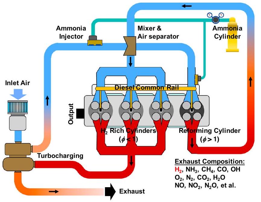
الشكل 1 | النموذج المفاهيمي لإعادة تدوير غاز الإصلاح داخل الأسطوانة (IRGR) لمحرك احتراق الأمونيا بقدرة الإشعال بالديزل التجريبي. هنا،يشير إلى نسبة التكافؤ العامة.
تفاعل نشاط الخليط القابل للاحتراق من خلال حقن الديزل المسبق يزيد أيضًا بشكل كبير من درجة حرارة الاحتراق و الانبعاثات، مما يؤدي إلى علاقات تبادل بين وانبعاثات الأمونيا غير المحترقة. علاوة على ذلك، تحت ظروف التشغيل المذكورة أعلاه، أظهرت النتائج التجريبية أن استراتيجية الحقن المسبق ستزيد أيضًا من الانبعاثات، التي تعوض فوائد تقليل انبعاثات غازات الدفيئة. مؤخرًا، شين وآخرون.عرضت محاكاة عددية لتوضيح إمكانيات حقن الديزل المبكر جداً في تقليل الأمونيا غير المحترقة وتحسين اقتصاد الوقود في وضع LPDF. مع محرك بقطر أسطوانة 137 مم يعمل بسرعة 910 دورة في الدقيقة، وجدوا أن حقن الديزل المبكر جداً فيبعد النقطة العليا للموت (aTDC) يمكن أن يقلل بوضوح من الأمونيا غير المحترقة، ولكن تم الإبلاغ أيضًا عن أن انبعاثات NO ستزداد من حوالي 1500 جزء في المليون إلى 6000 جزء في المليون عندما يتم تقديم توقيت حقن الديزل منإلى aTDC، الذي أظهر مرة أخرى العلاقة التبادلية بين الأمونيا غير المحترقة وانبعاثات.
من الواضح أن النتائج الأخيرة المستخلصة من أنواع المحركات المختلفة وظروف التشغيل تشير إلى أن الأمونيا غير المحترقة العالية و الانبعاثات هي تحديات حاسمة تعيق التطبيق الواسع لمحركات الاحتراق بالديزل التجريبي التي تعمل بالأمونيا. هناك حاجة ماسة إلى تقنيات لحل مشاكل الاختناق مثل ارتفاع نسبة الأمونيا غير المحترقة و الانبعاثات، العلاقة التبادلية بين الأمونيا غير المحترقة و الانبعاثات، والكفاءة المنخفضة. من المعروف أن إضافة الهيدروجين هي طريقة مفيدة لتحسين كفاءة احتراق الأمونيا ، أثناء استخدام إعادة تدوير غاز العادم (EGR) للتحكم فيانبعاث هو نهج شائع لمحركات الديزل والبنزين التقليديةفي ضوء ذلك، تم بدء مفهوم يُسمى إعادة تدوير غاز الإصلاح داخل الأسطوانة (IRGR) في الدراسة الحالية لتحسين الكفاءة الحرارية المعلنة وتقليل المواد غير المحترقة في الوقت نفسه.، وانبعاثات غازات الدفيئة لمحرك احتراق الأمونيا بالاشتعال بالديزل التجريبي. كما هو موضح في الشكل 1، في هذا المفهوم، يعمل أسطوانة واحدة من المحرك متعدد الأسطوانات بثراء في النسبة الاستوكيومترية ويتم تحلل الأمونيا الزائدة جزئيًا إلى هيدروجين تحت ظروف درجات الحرارة العالية داخل الأسطوانة، ثم يتم إعادة تدوير العادم من هذه الأسطوانة المخصصة لإعادة التشكيل إلى الأسطوانات الأخرى وبالتالي يمكن دمج مزايا الاحتراق الغني بالهيدروجين وإعادة تدوير غاز العادم. بالمقارنة مع نهج تجهيز مصلح إضافي خارج المحرك، فإن المفهوم في هذه الدراسة له المزايا التالية: (1) توفير حوالي 23% من طاقة الوقود بسبب فقدان نقل الحرارة من المصلح الخارجي.; (2) الحل مشكلة قصر عمر المحفز وارتفاع تكلفته؛ (3) تجنب تعقيد هيكل المحرك. يجب الإشارة إلى أن تقنية مماثلة تُسمى EGR المخصصة اقترحها ألجر وآخرون.في عام 2007 لتحسين تحمل نظام إعادة تدوير غازات العادم لمحرك البنزين ذو الاشتعال الشراري. النسخة الأولية من المخصصيتضمن محفز تحويل الماء والغاز في مجمع العادم لتعزيز تفاعل تحويل الماء والغاز (أي، )، وُجد أن كمية صغيرة من الهيدروجين (أي، حوالي المضافة في مجمع السحب مفيدة لتحسين كفاءة الاحتراق وأداء المحرك. بعد عامين، أجرى ألجير وآخرون.اقترح نسخة معدلة من نظام إعادة تدوير غاز العادم المخصص في عام 2009، ومن التعديلات الرئيسية استخدام محفز الأكسدة الجزئية في مجرى العادم للأسطوانة المخصصة لتحويل بعض من الهيدروكربونات غير المحترقة في العادم إلى CO و. وقد أفادوا أن نظام إعادة تدوير غاز العادم المخصص مفيد في تقليل استهلاك الوقود وتحسين استقرار المحرك. في عام 2014، تشادويل وآخرون.حسنت تقنية EGR المخصصة بشكل أكبر من خلال تحسين التعزيز ذي الصلة، والتحكم في EGR، وخلط EGR، وأنظمة الإشعال، وحصلت على خريطة أداء لمحرك بنزين حقن مباشر سعة 2.0 لتر. وأظهرت أن تقنية EGR المخصصة يمكن أن تحسن كفاءة المحرك بحوالي. لاحقًا، غوكيلبرغر وآخروندرسوا المزيد من إمكانيات تطبيق نظام إعادة تدوير غاز العادم المخصص لمحرك البنزين وقيموا أداء المحرك تحت أحمال محرك مختلفة. وأظهروا أن المحرك المزود بنظام إعادة تدوير غاز العادم المخصص لديه القدرة على العمل عند نسبة ضغط عالية وبالتالي يتمتع بكفاءة حرارية أعلى. علاوة على ذلك، أشاروا إلى أن إضافة محفز لتحويل الماء إلى غاز في مجرى العادم للأسطوانة المخصصة يمكن أن يعزز تفاعل تحويل الماء إلى غاز ويزيد من جودة إعادة تدوير غاز العادم. في السنوات الأخيرة، كانت هناك أيضًا بعض الدراسات التي تظهر أن نظام إعادة تدوير غاز العادم المخصص يمكن أن يحسن من تحمل التخفيف لمحرك الغاز الطبيعي ذو الاشتعال الشراري.بالمقارنة مع تقنية EGR المخصصة المذكورة أعلاه المقترحة لتحسين تحمل EGR لمحرك الاحتراق الشراري، يظهر محرك الاحتراق بالأمونيا مع إشعال الديزل التجريبي IRGR في الدراسة الحالية اختلافات من حيث استقلالية نظام سحب الهواء في الأسطوانة رقم 1 (أي، مستقل لـ IRGR مقابل مشترك مع أسطوانات أخرى لـ EGR المخصص)، وما إذا كان يُقترح وجود محفز EGR، ونمط الإشعال والاحتراق، والوقود (أي، الأمونيا لـ IRGR مقابل الوقود الكربوني مثل البنزين والغاز الطبيعي لـ EGR المخصص) وما إلى ذلك. خاصة، حتى الآن لم تكن هناك دراسة للتحقق من إمكانية تطبيق مفهوم مشابه على المحركات التي تعمل بالأمونيا.
في الدراسة الحالية، آلية تفاعل كيميائي للأمونيا المجمعة وتم تطوير احتراق الهيبتان ودمجه في منصة المحاكاة العددية، وتم استخدام محرك احتراق مزدوج يعمل بالديزل والامونيا بأربعة أسطوانات بدون نظام IRGR للحصول على البيانات التجريبية للتحقق من النماذج العددية وآلية الحركة الكيميائية، كما هو موضح في قسم “الطرق”. ثم، تم دراسة إمكانيات مفهوم IRGR في تحسين الكفاءة الحرارية وتقليل الانبعاثات عددياً تحت نسب طاقة الأمونيا المختلفة (أي، “سرعات المحرك (أي، 1000، 1500، 2000، 2500 دورة في الدقيقة)، توقيتات حقن الوقود (أي، من -20 إلىمستويات تعزيز الوقود في أسطوانة الإصلاح المخصصة. أخيرًا، يتم مناقشة النتائج الأولية وتلخيص النتائج.
النتائج
أسطوانة إصلاح مخصصة لمحرك IRGR
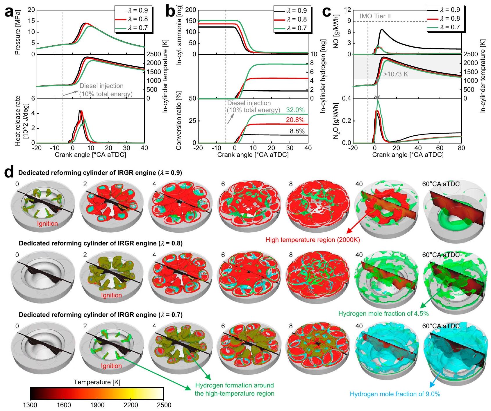
تظهر الشكل 2أ تطورات ضغط ودرجة حرارة داخل الأسطوانة بالإضافة إلى معدل إطلاق الحرارة لأسطوانة الإصلاح المخصصة تحت نسب فائض الهواء المختلفة، بينما يوضح الشكل 2د تطور المنطقة عالية الحرارة والمنطقة الغنية بالهيدروجين بالإضافة إلى توزيعات درجة حرارة داخل الأسطوانة لأسطوانة الإصلاح المخصصة. في الشكل 2د، تشير الأسطح العازلة الحمراء والخضراء والسيرانية إلى درجة حرارة 2000 كلفن، وكسور مول الهيدروجين من و ، على التوالي. بالنسبة للأسطوانة المخصصة للإصلاح، فإن
الشكل 2 | خصائص الاحتراق والانبعاثات لأسطوانة الإصلاح المخصصة تحت نسب الهواء الزائد المختلفة. أ درجة حرارة وضغط داخل الأسطوانة بالإضافة إلى معدل إطلاق الحرارة،كتلة الأمونيا والهيدروجين داخل الأسطوانة بالإضافة إلى نسبة تحويل الهيدروجين،NO داخل الأسطوانة و، تطوير منطقة درجات الحرارة العالية ومنطقة غنية بالهيدروجين بالإضافة إلى توزيع درجات الحرارة داخل الأسطوانة عند زوايا كرانك مختلفة. هنا،يشير إلى إجمالي الهواء الزائد نسبة. فييتم حساب نسبة تحويل الهيدروجين كنسبة بين طاقة الهيدروجين داخل الأسطوانة وطاقة الأمونيا المدخلة الكلية. فيتشير الأسطح العازلة الحمراء والخضراء والسيرانية إلى درجة حرارة 200 كلفن، ونسبة مول الهيدروجين من و ، على التوالي. (تظل النقاط التالية متسقة عبر جميع الحالات: 1000 دورة في الدقيقة، نسبة الطاقة للديزلحقن الديزل aTDC، ودرجة حرارة المدخل 318 كلفن). تم توفير بيانات المصدر كملف بيانات المصدر. نسب الهواء الزائد الإجمالية المعنية هنا هي 0.7 و 0.8، كما يتم عرض حالة نسبة الهواء الزائد الإجمالية 0.9 هنا لأغراض المقارنة. علاوة على ذلك، تظل النقاط التالية متسقة عبر جميع الحالات:درجة حرارة المدخل،نسبة الطاقة للديزل، وحقن aTDC. من خلال ملاحظة ملفات إطلاق الحرارة في الشكل 2a والمنطقة ذات درجة الحرارة العالية في الشكل 2d، يتبين أنه كلما زاد مستوى إثراء الوقود، زادت فترة تأخير الاشتعال. نظرًا لتأخير مرحلة الاحتراق، فإن الحالة التي تتميز بمستوى أعلى من إثراء الوقود تظهر ضغطًا ودرجة حرارة قصوى داخل الأسطوانة أقل. الملاحظة الدقيقة للصورة في الشكل 2d تُظهر أن الهيدروجين يتولد بشكل رئيسي بالقرب من المنطقة ذات درجة الحرارة العالية، حيث تحدث تفاعلات إنتاج الهيدروجين من تحلل الأمونيا وإعادة التشكيل (أي، و ) هي الأكثر إيجابية، وكلما زاد مستوى تخصيب الوقود، زادت كمية الهيدروجين المتولدة. على سبيل المثال، منطقة نسبة مول الهيدروجين على السطح المعزول المميز باللون السماوي صغيرة جداً لحالات نسبة الهواء الزائد الكلية 0.8 و 0.9، بينما يكون الأسطوانة بأكملها مليئة بتركيز عالٍ من الهيدروجين المعاد تشكيله والمتحلل عند 40 و aTDC لـ 0.7 نسبة الهواء الزائد الكلية. الشكل 2 ب يظهر تطورات كتلة الأمونيا والهيدروجين داخل الأسطوانة بالإضافة إلى نسبة تحويل الهيدروجين للأسطوانة المخصصة لإعادة التشكيل. هنا، يتم حساب نسبة تحويل الهيدروجين كنسبة طاقة الهيدروجين داخل الأسطوانة إلى إجمالي طاقة الأمونيا المدخلة. نظرًا لأن جميع الحالات تحافظ على درجة حرارة وضغط السحب الثابتين، فإن الكتلة الأولية للأمونيا داخل الأسطوانة تزداد مع زيادة مستوى إثراء الوقود.، وحالات نسبة الهواء الزائد الإجمالية 0.9، تقريبًا، ويتم إنتاج 1.7 ملغ من الهيدروجين خلال عمليات احتراق الأمونيا، على التوالي، مما يتوافق مع نسب تحويل الهيدروجين من، و يجب الإشارة إلى أنه من الضروري عند التشغيل الفعلي لمحرك احتراق الأمونيا IRGR الرجوع إلى تجارب تصميم محركات الهيدروجين لتجنب حدوث الانفجار العكسي.
الشكل 2c يظهر NO داخل الأسطوانة وتطورات أسطوانات الإصلاح المخصصة تحت نسب الهواء الزائد العامة المختلفة. النسب العامة للهواء الزائد المعنية هنا هي 0.7 و 0.8، كما تم تضمين حالة نسبة الهواء الزائد العامة 0.9 هنا للمقارنة. بالنسبة لمحرك احتراق الأمونيا، باستثناء تكوين NO الحراري، يتم أيضًا تشكيل NO الوقود بشكل حتمي خلال عمليات الاحتراق لأن وقود الأمونيا يحتوي على ذرة النيتروجين نفسها. نتيجة لذلك، يزيد NO داخل الأسطوانة بسرعة بعد بدء الاحتراق. من المعروف أن الشرط لتكوين كميات كبيرة من NO هو البيئات ذات درجات الحرارة العالية والغنية بالأكسجين. نظرًا لدرجة الحرارة داخل الأسطوانة وتركيز الأكسجين الأعلى نسبيًا، فإن حالة نسبة الهواء الزائد 0.9 تظهر أعلى تكوين لـ NO. يختلف ذلك عن محركات الديزل حيث يصل NO داخل الأسطوانة إلى ذروته ثم يبقى ثابتًا.بالنسبة لمحرك الذي يعمل بالامونيا هنا، يصل NO داخل الأسطوانة إلى ذروته ثم يمر بمرحلة انخفاض قبل الوصول إلى الحالة شبه المستقرة. يمكن أن يُعزى ذلك إلى عمليات DeNO الحرارية.التي تكون ردود أفعالها الرئيسية هي و . بشكل عام، تركيز NO عند توقيت فتح صمام العادم لأسطوانة الإصلاح المخصصة يكون أقل بكثير من حد IMO Tier II. داخل الأسطوانة يزداد أيضًا بسرعة بعد بدء الاحتراق، وذلك لأنتبدأ تفاعلات الإنتاج بمجرد بدء احتراق الأمونيا، وتشمل بشكل رئيسي التفاعلين التاليين و . منذ داخل الأسطوانةسوف يتم تحللها حرارياً فوقتُشير اللحظة التي تصل فيها درجة حرارة داخل الأسطوانة إلى 1073 كلفن في الرسم البياني لـالتطورات. يمكن رؤية اللحظة التييبدأ في الانخفاض يتزامن تقريبًا مع الوقت الذي تتجاوز فيه درجة حرارة داخل الأسطوانة 1073 كلفن. يجب ملاحظة أنيبدأ في إظهار اتجاه تصاعدي مرة أخرى بعد حوالي aTDC. هذا لأن تزداد تفاعلات الإنتاج هيمنة مقارنة بتفاعلات التحلل الحراري بسبب انخفاض درجة حرارة الأسطوانة في هذه المرحلة. وفقًا لدراسات حديثة حول محركات الإشعال الشراري للأمونيا، إن إضافة الهيدروجين بنسب صغيرة يمكن أن تحسن بوضوح الكفاءة الحرارية وتقلل من الأمونيا غير المحترقة. توضح الشكل 2ب أن نسبة تحويل الهيدروجين في أسطوانة الإصلاح المخصصة تحت مستويات إثراء الوقود المعنية تبلغ حواليإلى. في الأقسام التالية، يتضمن عادم أسطوانة الإصلاح المخصصة ، ، إلخ. سيتم إعادة تدويرها إلى الأسطوانات #2-4، وسيتم مقارنة ومناقشة أداء المحرك والانبعاثات لمحرك القاعدة ومحرك IRGR تحت نسب الطاقة المختلفة للديزل (أي، ، و مستوى إثراء الوقود في الأسطوانة رقم 1 (أي 0.7 و 0.8)، أوقات الحقن (أي من -20 إلىسرعات المحرك (1000، 1500، 2000 و2500 دورة في الدقيقة).
مقارنة بين محرك IRGR والمحرك الأساسي
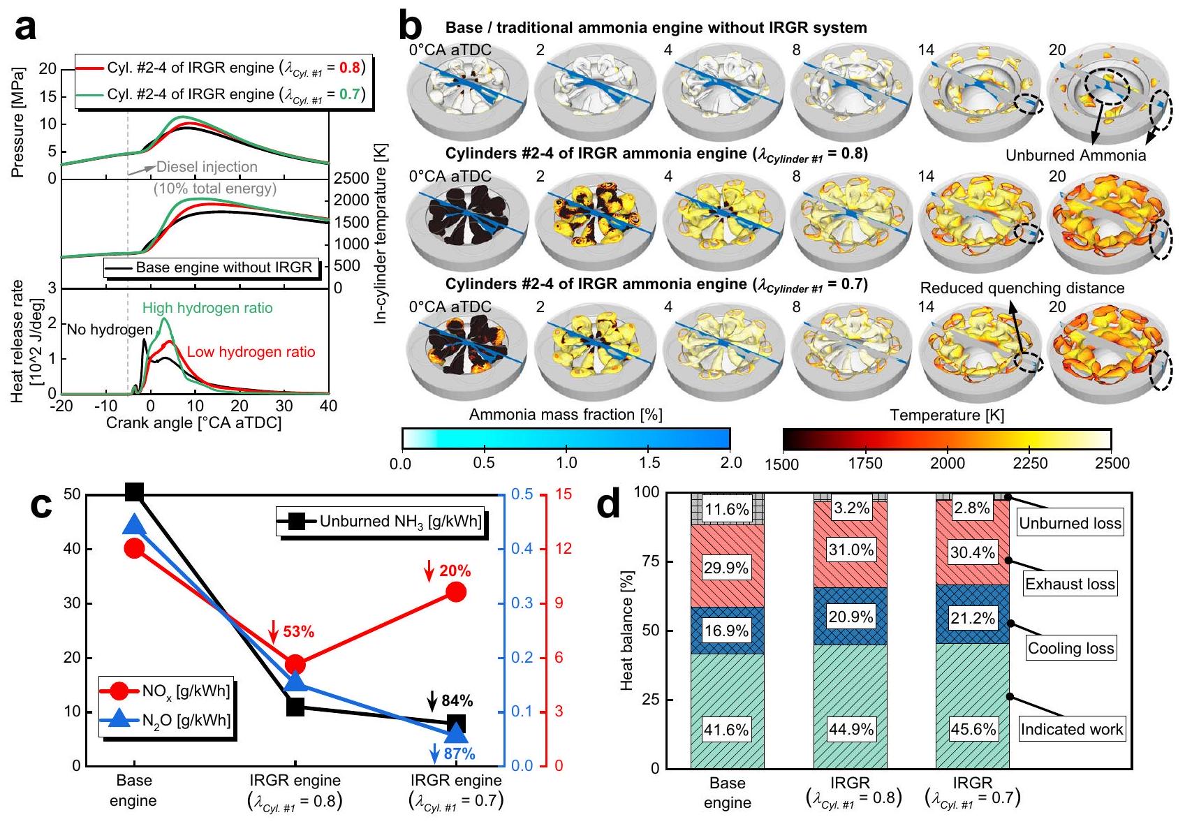
بالنسبة لمحرك IRGR، تعمل معظم الأسطوانات (أي الأسطوانات #2-4) تحت حالة إثراء الهيدروجين، وتسيطر خصائص الاحتراق لهذه الأسطوانات على أداء المحرك بالكامل. الشكل 3a يقدم مقارنة بين درجة الحرارة والضغط داخل الأسطوانة بالإضافة إلى معدل إطلاق الحرارة بين المحرك الأساسي بدون نظام IRGR والأسطوانات #2-4 من محرك IRGR. الثوابت التالية هي للمقارنة المباشرة: 1717 جول من إجمالي الطاقة المدخلة لكل أسطوانة،نسبة الطاقة للديزل، 1000 دورة في الدقيقة، وتوقيت حقن الديزل aTDC. نسبة الهواء الزائد الكلية لمحرك الأساس بدون نظام IRGR هي 1.5، بينما عند اعتبار إعادة تدوير غاز الإصلاح من الأسطوانة رقم 1، يتم تقليل قيمة الأسطوانات رقم 2-4 من محرك IRGR إلى 1.1. هنا، يتم تقييم خصائص الاحتراق للأسطوانات رقم 2-4 من محرك IRGR تحت مستويات مختلفة من إثراء الوقود للأسطوانة رقم 1 (أي، 0.7 و 0.8 نسب الهواء الزائد الكلية). يمكن ملاحظة أن تأخير الاشتعال ومدة الاحتراق متشابهة لمحرك الأساس والأسطوانات رقم 2-4 من محرك IRGR. ). هذا لأن ، ، وما إلى ذلك من العادم الناتج عن أسطوانة الإصلاح المخصصة يتم إعادة تدويره جميعًا إلى الأسطوانات #2-4، وتعزيز الاحتراق من خلال إضافة الهيدروجين وتثبيط الاحتراق من خلال الإدخال و تتعادل مع بعضها البعض في الأسطوانات #2-4. بالنسبة للأسطوانات #2-4 من محرك IRGR ( )، سيؤدي زيادة مستوى غنى الهيدروجين إلى زيادة معدل إطلاق الحرارة وتقليل طفيف في مدة الاحتراق، مما يؤدي إلى زيادة في ضغط ودرجة حرارة الأسطوانة القصوى.
الشكل 3ب يقدم مقارنة بين تطور اللهب وتوزيع كتلة الأمونيا بين المحرك الأساسي بدون نظام IRGR والأسطوانات #2-4 من محرك IRGR. حالة التشغيل متسقة مع الشكل 3أ. هنا، يتم تراكب معلومات درجة الحرارة على الأسطح المتساوية لنسبة الهواء الزائدة 1.1، وتكون المستويات المقطعية ملونة بكتلة الأمونيا. بشكل عام، فإن درجة حرارة اللهب في الأسطوانات #2-4 من محرك IRGR أقل من تلك في المحرك الأساسي، وهو ما يمكن أن يُعزى إلى الزيادة فيالحالة السابقة. عند الملاحظة الدقيقة لشرائح كتلة الأمونيا المئوية فيفي aTDC، يمكن ملاحظة أن هناك العديد من المواد غير المحترقةفي الفجوة بين المكبس ورأس الأسطوانة في محرك القاعدة، بينما لا يوجد تقريبًا أي أمونيا غير محترقة في فجوة الأسطوانات #2-4 من محرك IRGR.هذا لأن إضافة الهيدروجين تزيد من نشاط التفاعل الكيميائي للمزيج القابل للاحتراق وتقلل من مسافة الإخماد. بشكل عام، يمكن أن يقلل المفهوم الذي تم طرحه في هذه الدراسة بشكل كبير من الأمونيا غير المحترقة في محرك احتراق الأمونيا الذي يعمل بديزل الإشعال، وسيتم تقديم مزيد من التفاصيل حول تقليل الانبعاثات في الفقرات التالية.
الشكل 3ج يعرض مقارنة المواد غير المحترقة، و الانبعاثات بين محرك الأمونيا التقليدي/الأساسي بدون نظام IRGR ومحرك الأمونيا IRGR، بينما الشكل 3d يقدم مقارنة توازن الحرارة. هنا، موضوع المقارنة هو المحرك بالكامل بما في ذلك جميع الأسطوانات الأربع. تظل النقاط التالية ثابتة لجميع أنواع المحركات والأسطوانات: نسبة الطاقة للديزل توقيت الحقنعند 1000 دورة في الدقيقة، ودرجة حرارة مدخل 318 كلفن. علاوة على ذلك، بالنسبة للمحرك الأساسي والأسطوانات #2-4 من محرك IRGR، فإن إجمالي الطاقة المدخلة لكل أسطوانة ثابت عند 1717 جول. توضح الشكل 3c أن مفهوم IRGR يمكن أن يقلل تقريبًامن الأمونيا غير المحترقة، ويرجع ذلك أساسًا إلى أن إضافة الهيدروجين تزيد من نشاط التفاعل الكيميائي للمزيج القابل للاحتراق وتقلل بشكل كبير من الأمونيا غير المحترقة في حجم الفراغ، كما هو موضح في الشكل 3ب.تقلصت الانبعاثات بشكل كبير لمحرك IRGR، ويمكن أن تُعزى الأسباب إلى انخفاض محتوى الأكسجين والحد منتفاعلات الإنتاج. يمكن ملاحظة أنانبعاثات محرك الأمونيا IRGR أصغر بوضوح من تلك الخاصة بمحرك الأمونيا التقليدي/الأساسي. أولاً، يعود ذلك إلى انخفاض محتوى الأكسجين في محرك IRGR، مما يؤدي إلى تقليل تكوين الحرارة.. علاوة على ذلك، بالنسبة للأسطوانات #2-4 من محرك IRGR، يتم استبدال جزء صغير من الطاقة التي توفرها الأمونيا في الأصل بالهيدروجين المعاد تدويره من الأسطوانة #1، مما يساعد على تقليل تكوين الوقوديجب أن نلاحظ أن تقليلتنخفض الانبعاثات بمفهوم IRGR عند مستوى إثراء الوقود الأعلى في الأسطوانة رقم 1. وذلك لأن المزيد من الهيدروجين يتم إعادة تدويره من الأسطوانة رقم 1 إلى الأسطوانات رقم 2-4 عند مستوى إثراء الوقود المرتفع، مما يؤدي إلى تكوين المزيد من الحرارة.تظهر الشكل 3d أن الفقد غير المحترق قد انخفض منحواليعند استخدام تقنية IRGR، ويرجع ذلك أساسًا إلى تقليل الأمونيا غير المحترقة في حجم الإزاحة. خسائر التبريد لمحرك IRGR أعلى من تلك الخاصة بالمحرك الأساسي، ويمكن أن يُعزى ذلك إلى ارتفاع درجة حرارة الأسطوانة بسبب تحسين الاحتراق في محرك IRGR، كما هو موضح في الشكل 3a. بشكل عام، هذه الفكرة مفيدة لتحسين كفاءة استهلاك الوقود نظرًا للتقليل الكبير في الخسائر غير المحترقة.
إمكانات IRGR تحت ظروف تشغيل مختلفة
تظهر الشكل 3 أن مفهوم IRGR هو طريقة فعالة لتحسين الكفاءة الحرارية وتقليل الأمونيا غير المحترقة في الوقت نفسه.، و الانبعاثات تحت نسبة الطاقة للديزل، وتوقيت حقن الوقود aTDC. في هذا القسم، سيتم دراسة تأثيرات تقنية IRGR على تحسين الكفاءة الحرارية وتقليل الانبعاثات تحت ظروف أكثر
الشكل 3 | مقارنة بين محرك الأمونيا التقليدي/الأساسي بدون نظام IRGR ومحرك الأمونيا IRGR. أ مقارنة بين درجة الحرارة والضغط داخل الأسطوانة بالإضافة إلى معدل إطلاق الحرارة بين محرك الأمونيا التقليدي بدون نظام IRGR والأسطوانات #2-4 من محرك الأمونيا IRGR، ب مقارنة بين تطور اللهب وتوزيع كتلة الأمونيا بين محرك الأمونيا التقليدي بدون نظام IRGR والأسطوانات #2-4 من محرك الأمونيا IRGR عند زوايا كرانك مختلفة،مقارنة غير المحترق، و الانبعاثات بين محرك الأمونيا التقليدي/الأساسي بدون نظام IRGR ومحرك الأمونيا مع نظام IRGR، مقارنة توازن الحرارة بين القاعدة/
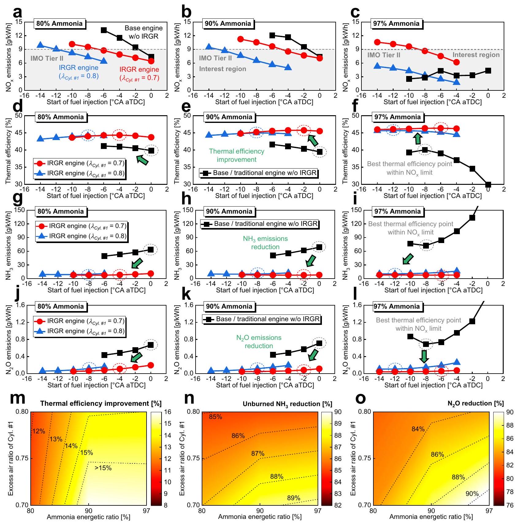
محرك الأمونيا التقليدي بدون نظام IRGR ومحرك الأمونيا بنظام IRGR. هنا،يشير إلى نسبة الهواء الزائد الكلية. في، يتم تراكب معلومات درجة الحرارة على الأسطح المتساوية لنسبة الهواء الزائدة 1.1، وتكون الطائرات المقطعية ملونة بكتلة الأمونيا.، موضوع المقارنة هو المحرك بالكامل بما في ذلك جميع الأسطوانات الأربع. (تظل النقاط التالية متسقة لجميع أنواع المحركات والأسطوانات: نسبة الطاقة في الديزل درجة حرارة المدخل 318 كلفن، وتوقيت حقن الديزل aTDC؛ بالنسبة لمحرك الأمونيا التقليدي والأسطوانات #2-4 من محرك الأمونيا IRGR، فإن إجمالي الطاقة المدخلة لكل أسطوانة ثابت عند 1717 جول). تم توفير بيانات المصدر كملف بيانات مصدر. نسب الطاقة للأمونيا ومجموعة واسعة من توقيتات حقن الوقود لاستكشاف إمكانيات مفهوم IRGR بالكامل، كما هو موضح في الشكل 4. من أجل مقارنة عادلة، فإن موضوع المقارنة هو المحرك بالكامل بما في ذلك جميع الأسطوانات الأربع، حيث يتم الحفاظ على معلمات مهمة مثل 1000 دورة في الدقيقة ودرجة حرارة المدخل 318 كلفن ثابتة لجميع أنواع المحركات والأسطوانات، وتظل الطاقة المدخلة الإجمالية لكل أسطوانة ثابتة عند 1717 جول للمحرك الأساسي والأسطوانات #2-4 من محرك IRGR. الشكليقدم المقارنة بين الانبعاثات بين محرك الأمونيا التقليدي/الأساسي بدون نظام IRGR ومحرك الأمونيا مع نظام IRGR تحت نسبة الطاقة للأمونيا ، و ، ومعيار IMO Tier IIالحد موضح في الشكل لتسليط الضوء على نطاق اهتمام توقيتات حقن الوقود. في معظم الحالات، يمكن لتقنية IRGR تقليل الانبعاثات الناتجة عن انخفاض محتوى الأكسجين بسبب تأثيرات إعادة تدوير غاز الإصلاح، مما يمدد النطاق المفيد لتوقيت حقن الوقود. الشكل يظهر مقارنة الكفاءة الحرارية المحددة، بينما الشكل.يقدم مقارنة للمواد غير المحترقة الانبعاثات. وُجد أن حقن الديزل المتقدم في نطاق معين يساعد في تقليل انبعاثات الأمونيا غير المحترقة، ويمكن أن يُعزى ذلك إلى زيادة فترة مزج الديزل والأمونيا والتفاعل الكيميائي في توقيت الحقن المبكر. تزداد الكفاءة الحرارية المعلنة تدريجياً مع تقدم توقيت حقن الديزل ضمن نطاق معين، ويرجع ذلك أساساً إلى زيادة الحرارة. تم إصدارها بالقرب من TDC وزيادة كفاءة احتراق الأمونيا. ومع ذلك، فإن التقدم الإضافي في توقيت الحقن سيقلل من درجة إطلاق الحرارة في حجم ثابت وسيؤدي إلى تدهور اقتصاد الوقود. نظرًا لأن الأمونيا غير المحترقة قد تجاوزت بالفعلالكفاءة الحرارية المحددة لمحرك الأمونيا التقليدي/الأساسي بدون نظام IRGR تنخفض correspondingly إلى أقل منفينسبة الطاقة للأمونيا. لحسن الحظ، يظل مفهوم IRGR فعالاً للغاية حتى فينسبة الطاقة للأمونيا، حيث يمكن أن تقلل من الأمونيا غير المحترقة إلى حوالي كيلوواط ساعة وزيادة الكفاءة الحرارية المشار إليها إلى حوالي . الـتقليل الانبعاثات وزيادة نسبة الطاقة من الأمونيا مرتبطان بشكل إيجابي. ومع ذلك، بالنسبة لمحرك الأمونيا التقليدي/الأساسي بدون نظام IRGR، عندما تزداد نسبة الطاقة من الأمونيا منإلى، الـتزداد الانبعاثات أيضًا من حوالي 0.5 إلى. منذ لديه تأثير دفيء حول 298 مرة من، الـستؤدي الانبعاثات عند هذا المستوى إلى تأثير غازات الدفيئة يعادلانبعاثات من وضع الديزل النقي (أي حوالي )، وسيتم تقديم المزيد من التفاصيل حول إمكانيات مفهوم IRGR في تقليل انبعاثات غازات الدفيئة في القسم التالي ‘تكنولوجيا IRGR لتقليل غازات الدفيئة’.
في الشكل 4، أفضل نقاط الكفاءة الحرارية المشار إليها ضمن معايير IMO Tier IIتُبرز الحدود بواسطة الدوائر المتقطعة، وتُقارن هذه النقاط الأفضل في الشكل.. لمحرك IRGR، المزيد
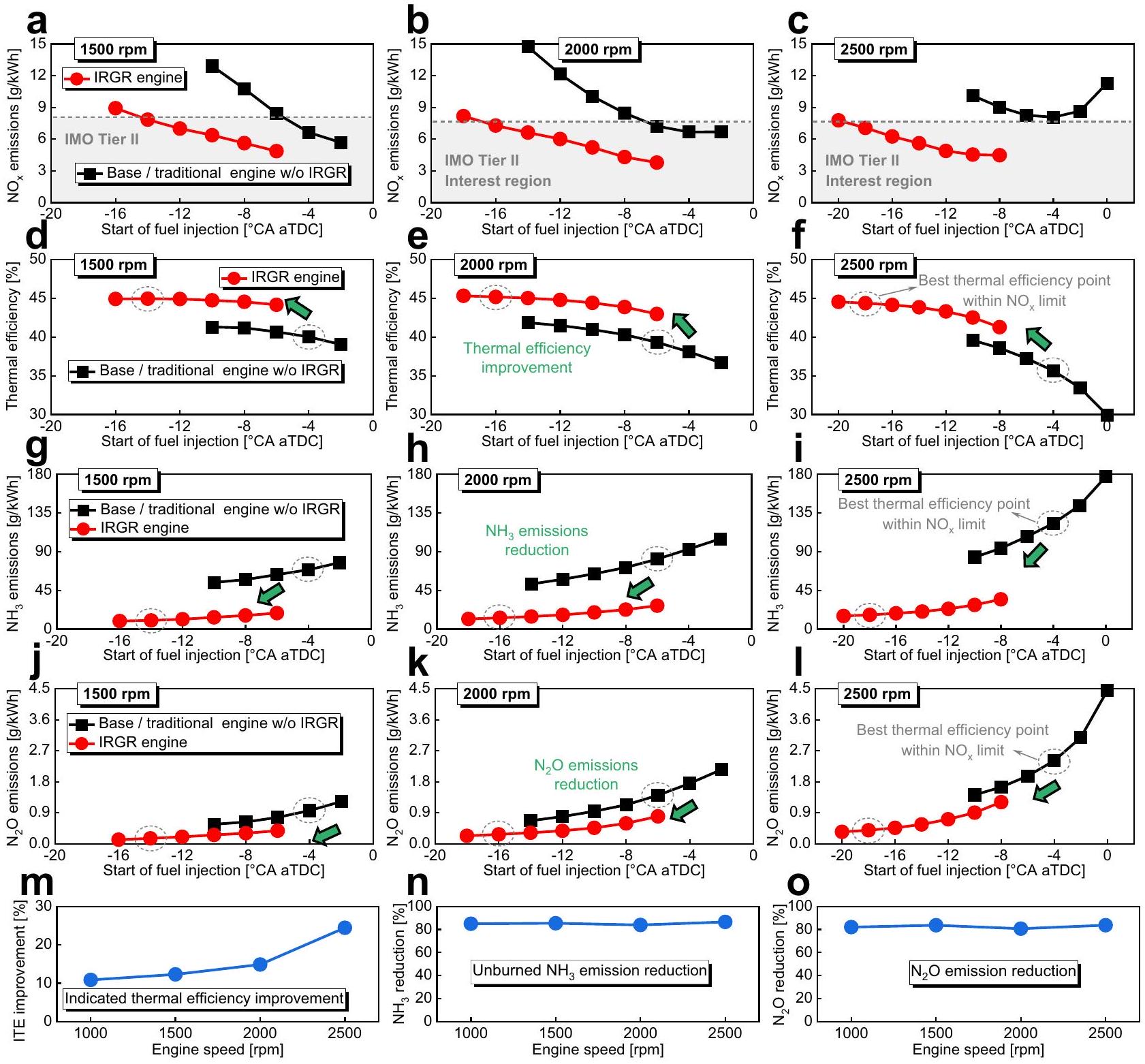
الشكل 4 | تأثيرات تكنولوجيا IRGR تحت نسبة الطاقة للأمونيا، و . مقارنة a-cانبعاثاتمقارنة الكفاءة الحرارية المحددة،-i مقارنة غير المحترقانبعاثات-أنا مقارنة بـ الانبعاثات بين محرك الأمونيا التقليدي/الأساسي بدون نظام IRGR ومحرك الأمونيا مع نظام IRGR تحت نسبة الطاقة للأمونيا و آثار تقنية IRGR على تحسين الكفاءة الحرارية المشار إليها، غير المحترقخفض الانبعاثات،خفض الانبعاثات. هنا،يشير إلى نسبة الهواء الزائد العامة، وموضوع المقارنة هو المحرك بالكامل بما في ذلك جميع الأسطوانات الأربع. أفضل نقاط ITE ضمن مستوى IMO Tier IIتُبرز الحدود بواسطة الدوائر المتقطعة في، وتتم مقارنة هذه النقاط الأفضل في . (تظل النقاط التالية ثابتة لجميع أنواع المحركات والأسطوانات: 1000 دورة في الدقيقة ودرجة حرارة المدخل 318 كلفن؛ بالنسبة لمحرك الأمونيا التقليدي/الأساسي والأسطوانات #2-4 من محرك الأمونيا IRGR، فإن إجمالي الطاقة المدخلة لكل أسطوانة ثابت عند 1717 جول). يتم توفير بيانات المصدر كملف بيانات مصدر. يتم إعادة تدوير الهيدروجين إلى الأسطوانات #2-4 مع زيادة مستوى إثراء الوقود في الأسطوانة #1، مما يساهم في تقليل انبعاثات الأمونيا غير المحترقة، كما هو موضح في الشكل 4ن. علاوة على ذلك، كما هو موضح في الشكل 40، كلما زاد مستوى إثراء الوقود في الأسطوانة #1، زادت الأهمية.الخفض. وذلك لأن زيادة إضافة الهيدروجين في الأسطوانات #2-4 ستزيد من درجة الحرارة داخل الأسطوانة وتعززتفاعلات التحلل الحراري. توضح الشكل 4 م أن تقنية IRGR مفيدة في تحسين الكفاءة الحرارية المشار إليها، ويعزى ذلك بشكل رئيسي إلى تحسين كفاءة الاحتراق وتقليل المواد غير المحترقة. الأمونيا من خلال إضافة الهيدروجين. هناك اتجاه عام يشير إلى أن ميزة تقنية IRGR في تحسين الكفاءة الحرارية وتقليل الانبعاثات تكون أكثر وضوحًا عند نسب الطاقة للأمونيا الأعلى، مما يدل على إمكانية تقنية IRGR لزيادة نسبة استبدال الديزل. عمومًا، عندما تتغير نسبة الطاقة للأمونيا منإلى ونسبة الهواء الزائد العامة لأسطوانة الإصلاح المخصصة تتراوح من 0.7 إلى 0.8، يمكن لمفهوم IRGR تقليل المواد غير المحترقة و انبعاثات بمقدار لا يقل عن و على التوالي، وزيادة الكفاءة الحرارية المشار إليها بمقدار لا يقل عنمظهراً فعالية تقنية IRGR. خاصةً،
الشكل 5 | تأثيرات تقنية IRGR تحت سرعات المحرك 1500 و2000 و2500 دورة في الدقيقة. أ-ج مقارنة بـانبعاثاتمقارنة الكفاءة الحرارية المحددة،-i مقارنة غير المحترق الانبعاثات، مقارنة j-I الانبعاثات بين محرك الأمونيا التقليدي بدون نظام IRGR ومحرك الأمونيا مع نظام IRGR تحت سرعات المحرك 1500 و2000 وآثار تقنية IRGR على تحسين الكفاءة الحرارية المشار إليهاغير محترقخفض الانبعاثاتتقليل الانبعاثات. هنا، موضوع المقارنة هو المحرك بالكامل بما في ذلك جميع الأسطوانات الأربعة. بالنسبة لمحرك الأمونيا IRGR، نسبة الهواء الزائد الإجمالية لأسطوانة الإصلاح المخصصة هي 0.8. أفضل نقاط ITE ضمن معايير IMO Tier IIتُبرز الحدود بواسطة الدوائر المتقطعة في، وتتم مقارنة هذه النقاط الأفضل في . (تظل الأمور التالية متسقة لجميع أنواع المحركات والأسطوانات: نسبة الطاقة للأمونيا ودرجة حرارة المدخل 318 كلفن؛ بالنسبة لمحرك الأمونيا التقليدي والأسطوانات #2-4 من محرك الأمونيا IRGR، فإن إجمالي الطاقة المدخلة لكل أسطوانة ثابت عند 1717 جول). تم توفير بيانات المصدر كملف بيانات مصدر. عندنسبة الطاقة للأمونيا ونسبة الهواء الزائد العامة 0.7 للأسطوانة رقم 1، يمكن لمحرك IRGR زيادة الكفاءة الحرارية المعلنة بـ وتقليل المواد غير المحترقة بواسطةبواسطةمقارنة بمحرك الأمونيا التقليدي/الأساسي بدون IRGR.
تظهر الشكل 5 فعالية مفهوم IRGR تحت سرعة محرك أعلى (أي 1500 و2000 و2500 دورة في الدقيقة). هنا، نسبة الطاقة للأمونيا ثابتة عند. بشكل عام، زيادة سرعة المحرك ستقلل بشكل كبير من الكفاءة الحرارية المعلنة وتزيد من الأمونيا غير المحترقة وانبعاثات محركات الأمونيا التقليدية/الأساسية بدون IRGR. وذلك لأن المدة الزمنية للتفاعلات الكيميائية تنخفض بشكل كبير عند سرعات المحرك العالية، مما يزيد من تفاقم عيوب خصائص الاحتراق السيئة لوقود الأمونيا. عند 2500 دورة في الدقيقة،انبعاثات القاعدة/ محرك الأمونيا التقليدي بدون نظام IRGR قد تجاوزفي منطقة المصلحة، مما يؤدي إلى تأثير غازات الدفيئة المعادل الذي يشبه تأثير وضع الديزل النقي. لا شك أن هذا سيعيق بشكل كبير التطبيقات المستقبلية لمحركات الأمونيا التقليدية. مشابهة للشكل 4، فإن أفضل نقاط الكفاءة الحرارية المعلنة ضمن مستوى IMO Tier IIتُبرز الحدود أيضًا بواسطة الدوائر المتقطعة، وتُقارن هذه النقاط الأفضل في الشكل 5م-و. وليس من المستغرب أن إمكانيات تقنية IRGR لتحسين الكفاءة الحرارية المعلنة تكون أكثر وضوحًا عند سرعات المحرك الأعلى كما هو موضح في الشكل 5م. خاصة، عند 2500 دورة في الدقيقة، يمكن لمفهوم IRGR زيادة الكفاءة الحرارية المعلنة بـ مقارنة بمحرك الأمونيا التقليدي/الأساسي بدون IRGR. في نفس الوقت، يمكنه تقليل المواد غير المحترقة بواسطة و بواسطة.
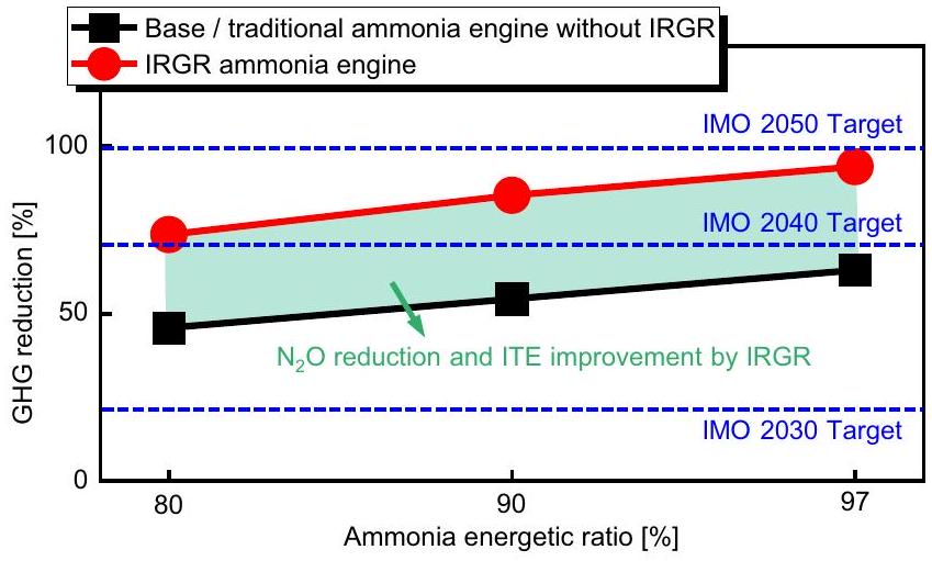
الشكل 6 | تأثيرات تقنية IRGR على تقليل انبعاثات غازات الدفيئة تحت نسب الطاقة المختلفة للأمونيا. هنا، تشير البيانات إلى أفضل نقاط الكفاءة الحرارية المحددة في الشكل 4، والقاعدة الأساسية هي وضع الديزل النقي التقليدي. موضوع المقارنة هو المحرك بالكامل بما في ذلك الأسطوانات الأربع، ويتم حساب انبعاثات غازات الدفيئة كـ (تظل القيم التالية ثابتة لجميع أنواع المحركات والأسطوانات: 1000 دورة في الدقيقة ودرجة حرارة المدخل 318 كلفن؛ بالنسبة لمحرك الديزل التقليدي النقي، ومحرك الأمونيا التقليدي/الأساسي، والأسطوانات #2-4 من محرك الأمونيا IRGR، فإن إجمالي الطاقة المدخلة لكل أسطوانة ثابت عند 1717 جول). يتم توفير بيانات المصدر كملف بيانات مصدر.
تكنولوجيا IRGR لتقليل انبعاثات غازات الدفيئة
تظهر الشكل 6 آثار تقنية IRGR على تقليل انبعاثات غازات الدفيئة (أي، ) تحت نسب الطاقة المختلفة للديزل. هنا، تشير البيانات إلى أفضل نقاط الكفاءة الحرارية المحددة في الشكل 4، والقاعدة هي وضع الديزل النقي التقليدي. بالنسبة لمحرك الأمونيا التقليدي/الأساسي بدون نظام IRGR، على الرغم من أن 97% من إجمالي الطاقة يتم توفيرها بواسطة وقود الأمونيا، فإن هدف IMO 2040 هو لا يزال تقليل انبعاثات غازات الدفيئة غير قابل للتحقيق. ويرجع ذلك أساسًا إلى تشكيلانبعاث، الذي له تأثير دفيء يعادل حوالي 298 مرة من، يعوض فوائد تقليل غازات الدفيئة. ومع ذلك، يمكن لمحرك الأمونيا IRGR أن يقلل بشكل كبير من انبعاثات غازات الدفيئة مقارنة بمحرك الأمونيا التقليدي/الأساسي بدون نظام IRGR لأنه يمكن أن يقلل بشكل كبير من الانبعاثات وتحسين الكفاءة الحرارية بشكل كبير. خاصة، في نسبة الطاقة الديزلية، يتمكن محرك الأمونيا IRGR من تقليل انبعاثات غازات الدفيئة بـ مقارنة بمحرك الأمونيا الأساسي بدون IRGR. في الوقت نفسه، فإنه قادر على تقليل انبعاثات غازات الدفيئة بـمقارنةً بوضع الديزل النقي التقليدي.
نقاش
في هذه الورقة، يتم تقديم مفهوم يُسمى إعادة تدوير غاز الإصلاح داخل الأسطوانة (IRGR) لتحسين الكفاءة الحرارية وتقليل المواد غير المحترقة في الوقت نفسه.، وانبعاثات غازات الدفيئة لمحرك الاحتراق بالأمونيا الذي يعمل بالديزل التجريبي. تم تطوير آلية تفاعل كيميائي للاحتراق المشترك للأمونيا و n -هيبتان تتكون من 65 نوعًا و344 تفاعلًا (أي، الكود التكميلي 1 والكود التكميلي 2) وتم دمجها في منصة المحاكاة العددية، والتي تم التحقق من صحتها بعد مقارنتها بالبيانات التجريبية لمحرك الاحتراق بالأمونيا الذي يعمل بالديزل التجريبي رباعي الأسطوانات بدون نظام IRGR. تم دراسة إمكانيات مفهوم IRGR في تحسين الكفاءة الحرارية وتقليل الانبعاثات عدديًا تحت نسب طاقة ديزل مختلفة، وسرعات محرك، وأوقات حقن الوقود، ومستويات إثراء الوقود للأسطوانة رقم 1.
يمكن للنماذج المحاكاة مع الآلية التي تم تطويرها في هذه الدراسة التنبؤ بشكل جيد بإطلاق الحرارة التجريبي وتطورات ضغط الأسطوانة تحت نسب الطاقة المختلفة للأمونيا.، ) وأحمال المحرك (أي، )، وتظهر أفضل التوقعات لانبعاثات العادم. بالنسبة للأسطوانة المخصصة لإعادة التشكيل في محرك IRGR، يتم توليد الهيدروجين بشكل رئيسي بالقرب من منطقة الحرارة العالية، حيث تكون تفاعلات إنتاج الهيدروجين من إعادة تشكيل الأمونيا والتحلل أكثر إيجابية. عندما يعمل الأسطوانة المخصصة للإصلاح في حالة غنية بالوقود بنسبة 0.7 و 0.8 من نسبة الهواء الزائد الكلية، وتكون نسب تحويل الهيدروجين هي و على التوالي. بسبب نقص الأكسجين، فإن تكوين NO وفي الأسطوانة المخصصة للإصلاح تكون ضئيلة جداً مقارنة بمحرك الأمونيا التقليدي/الأساسي بدون نظام IRGR. بالنسبة للأسطوانات الغنية بالهيدروجين (أي، الأسطوانات #2-4) من محرك IRGR، فإن إضافة الهيدروجين تزيد من نشاط التفاعل الكيميائي للمزيج القابل للاحتراق وتقلل من مسافة الإخماد، مما يساعد بشكل كبير في تقليل الأمونيا غير المحترقة في حجم الفراغ. علاوة على ذلك، بسبب انخفاض محتوى الأكسجين الناتج عن إعادة تدوير غاز الإصلاح، فإن NO وتُ suppress أيضًا ردود الفعل الإنتاجية. عندنسبة الطاقة للديزل عند 1000 دورة في الدقيقة، يمكن لمحرك IRGR زيادة الكفاءة الحرارية المعلنة بـ وتقليل المواد غير المحترقة بواسطةبواسطة (أي، ) بواسطة مقارنة بمحرك الأمونيا التقليدي/الأساسي بدون IRGR. في نفس الوقت، فإنه قادر على تقليل البصمة الكربونية بـ وغازات الدفيئة بواسطة مقارنةً بوضع الديزل النقي التقليدي. عند الديزل و2500 دورة في الدقيقة، يمكن لمفهوم IRGR زيادة الكفاءة الحرارية المعلنة بـ وتقليل المواد غير المحترقة بواسطة و بواسطة مقارنة بمحرك الأمونيا التقليدي الأساسي بدون IRGR. تشير المحاكاة التفصيلية ثلاثية الأبعاد للديناميكا الهوائية الحاسوبية إلى أن مفهوم IRGR يمكن أن يحل مشاكل الاختناق مثل الارتفاع في وانبعاثات الأمونيا غير المحترقة، وكفاءة حرارية منخفضة، وعلاقة تبادل بين غير المحترق و انبعاثات في تحسين الاحتراق لمحرك الاحتراق الأموني التقليدي الذي يعمل بديزل الطيار.
طرق
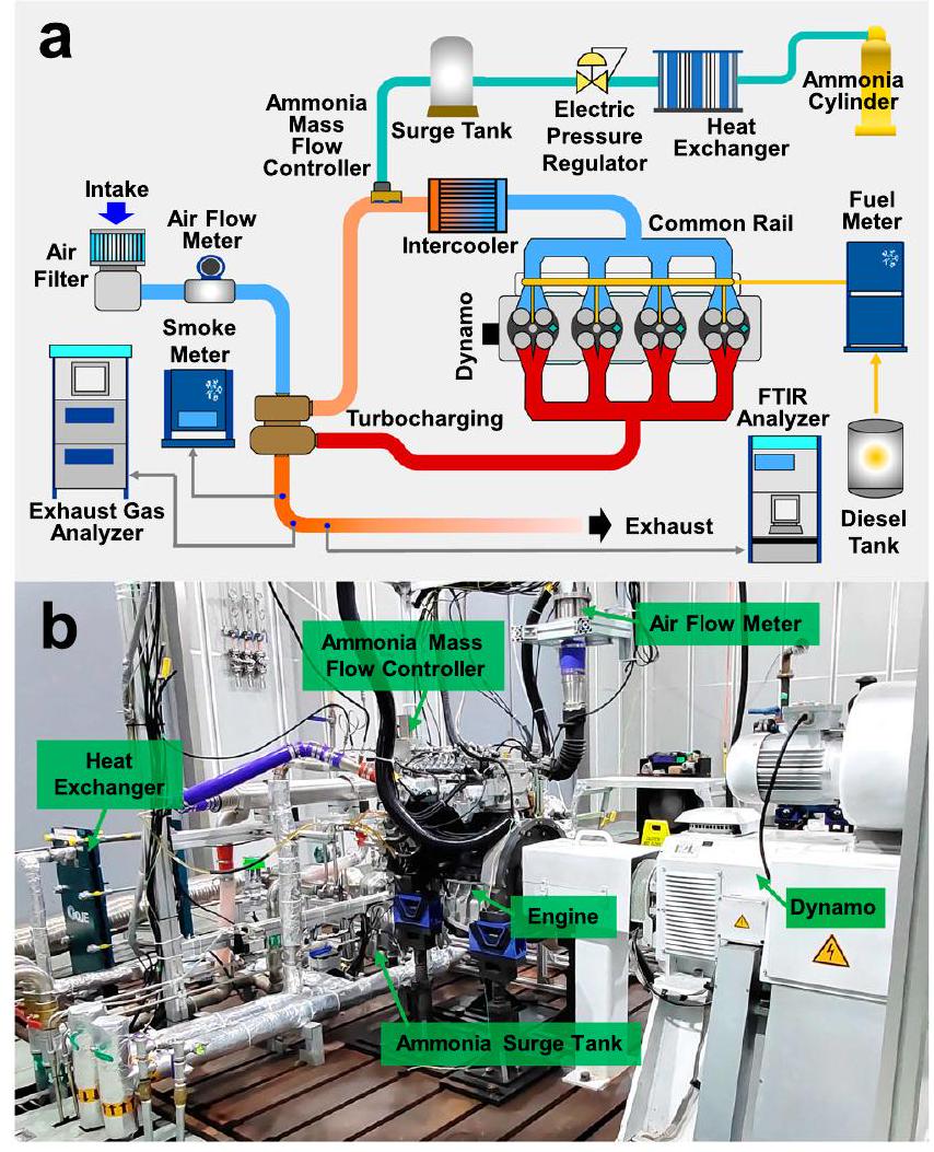
إعدادات تجريبية في هذه الورقة، تم استخدام محرك ديزل مزدوج الوقود بأربعة أسطوانات يعمل بالأمونيا بقطر 95 مم بدون نظام IRGR (أي المحرك الأساسي) للحصول على البيانات التجريبية للتحقق من آلية الكيمياء الحركية والنموذج العددي. يوضح الشكل 7a المخطط التخطيطي للنظام الكامل للمحرك الأساسي، الذي يتكون بشكل رئيسي من المحرك ومقياس الديناميكا، ونظام تزويد الوقود بالأمونيا، ونظام حقن الوقود التجريبي عالي الضغط، ونظام السحب، ونظام قياس انبعاثات العادم، بينما يعرض الشكل 7b صورة فعلية للمحرك الأساسي. يوضح الجدول 1 مواصفات المحرك وظروف التشغيل التجريبية تحت نسب طاقة أمونيا مختلفة. بالنسبة للتجارب، تم تزويد الأمونيا الغازية عند ضغط 0.6 ميغاباسكال قبل المبرد، وتم حقن وقود الديزل مباشرة في الأسطوانة عند ضغط 120 ميغاباسكال. هنا، تم استخدام جهاز التحكم في تدفق كتلة الأمونيا من بروكس ومقياس تدفق كتلة الوقود AVL 735 للحصول على معدلات تدفق الكتلة للأمونيا ووقود الديزل، على التوالي. تم استخدام مقياس الديناميكا الكهربائية HORIBA LI250 AC لقياس عزم الكبح والتحكم في سرعة المحرك، وNI PXI للتحكم في نظام المحرك، ومحولات الضغط AVL GH15DK لقياس ضغط داخل الأسطوانة. علاوة على ذلك، فإن العادم و تم قياسها بواسطة HORIBA MEXA-ONE-RS، والانبعاثات غير المحترقة و تم الحصول عليها بواسطة محلل الغاز بالأشعة تحت الحمراء بتقنية تحويل فورييه HORIBA FTX-ONE-CS.
بناء النماذج العددية
تم إجراء المحاكاة العددية باستخدام حزمة كود CONVERGE، وكانت هندسة غرفة احتراق المحرك متوافقة مع المحرك التجريبي في قسم “الإعدادات التجريبية”. امتد النطاق المحسوب من إغلاق صمام السحب إلى فتح صمام العادم، بما في ذلك عمليات الضغط، حقن الديزل التجريبي، خلط رذاذ الديزل وخلط الأمونيا والهواء، الاحتراق، التمدد، وعمليات نقل الحرارة، وتم ضبط وسائط العمل داخل الأسطوانة لتكون مختلطة بشكل موحد عند توقيت إغلاق صمام السحب. بالنسبة لمحرك الأمونيا مع إشعال الديزل التجريبي ونظام IRGR (أي، محرك IRGR)، كانت المحاكاة للأسطوانة المخصصة لإعادة التشكيل تحت ظروف غنية بالوقود (أي، الأسطوانة).
الجدول 1 | مواصفات المحرك وظروف التشغيل التجريبية تحت نسب الطاقة المختلفة للأمونيا للمحرك الأساسي بدون نظام IRGR للتحقق من آلية الديناميكا الكيميائية والنماذج العددية
المعلمات
قيمة
مواصفات المحرك
4 أسطوانات بدون IRGR
مللسكتة (مم)
قطر ثقب الفوهة (مم)رقم
نسبة الضغط
حوالي 17.5
حمولة المحرك (%)
75
ضغط الفعّالية المتوسطة للفرامل (ميغاباسكال)
0.7
ضغط حقن الديزل (ميغاباسكال)
١٢٠
توقيت حقن الديزل aTDC)
-2
-6
-5
نسبة الطاقة للأمونيا (%)
40
٨٠
90
ضغط إمداد الأمونيا (ميغاباسكال)
0.6
درجة حرارة المدخل (ك)
سرعة المحرك (دورة في الدقيقة)
1000
الشكل 7 | إعداد التجربة لمحرك الاحتراق المزدوج بالديزل والامونيا بدون نظام إعادة تدوير غاز الإصلاح داخل الأسطوانة (أي، المحرك الأساسي). أ رسم تخطيطي لنظام المحرك بالكامل، ب صورة فعلية للمحرك.
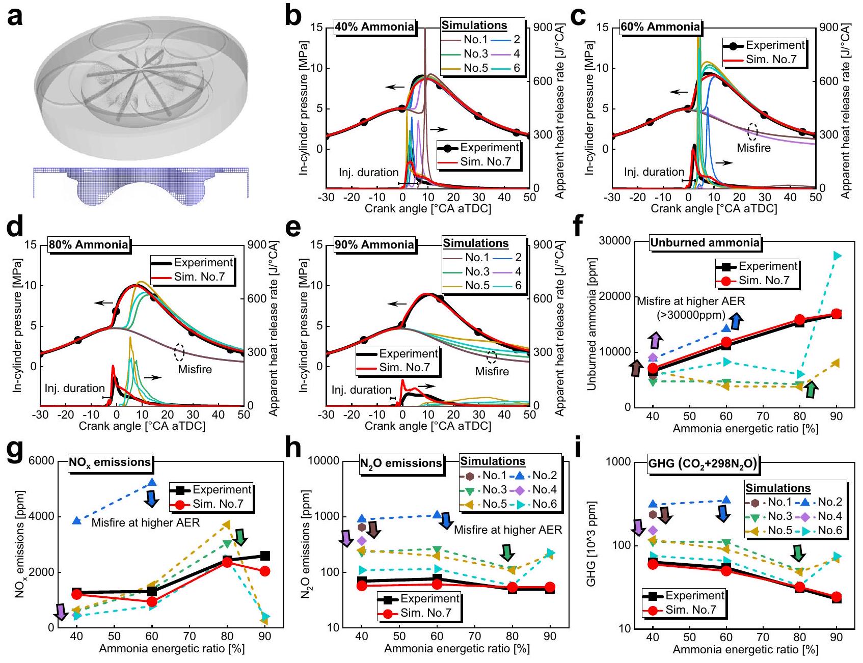
#1) تم إجراء التجارب أولاً، ثم تم حساب تركيبة المدخل للأسطوانات الثلاثة الغنية بالهيدروجين الأخرى (أي الأسطوانات #2-4) وفقًا لتركيبة العادم للأسطوانة المخصصة لإعادة التشكيل. تعرض الشكل 8a تفاصيل المجال الحسابي والشبكة بالقرب من النقطة العليا للمكبس. تم تعيين الشبكة الأساسية إلى 1.8 مم، وتم تطبيق تحسين الشبكة الثابتة لمنطقة بالقرب من الفوهة على مستويين، وتم استخدام تحسين الشبكة التكيفي في الأسطوانة على مستويين. بالنسبة لجميع أنواع المحركات والأسطوانات، تم استخدام معادلة RANS المرتبطة بنموذج RNG k-ɛ.ونموذج هان ورايتزتم استخدامهما لحساب تدفق الاضطراب وانتقال الحرارة، على التوالي. تم استخدام الجسيم اللاغرانجي لمحاكاة حقن وقود الديزل، مع ظاهرة كلفن-هلمهولتز-رايلي-تايلورلتحطيم الرذاذ، السحب الديناميكيلسحب القطرات، بدون عداد للوقتلتصادم القطرات، وفروسلينغلتبخر القطرات. تم محاكاة عمليات الاحتراق باستخدام محلل SAGE وآلية الكيمياء الحركية الأحدث للأمونيا/الن-هيبتان المبلغ عنها في (أي، رقم 1 في الجدول 2) والآليات التي تم دمجها/تطويرها من قبل الدراسة الحالية (أي، رقم 2-رقم 7 في الجدول 2) يتم مقارنتها مع بيانات التجربة في القسم التالي ‘تحقق من النماذج العددية’.
بالنسبة للآليات المدمجة (أي، رقم 2-رقم 6)، تم اختيار الن-هبتان (أي، C7) كبديل لوقود الديزل ودمجه مع آلية الديناميكا الكيميائية للأمونيا المستخدمة على نطاق واسع في السنوات الأخيرة.الآلية التي تم تطويرها في هذه الدراسة (أي رقم 7) تحتوي على نفس 344 تفاعل كما في رقم 6، ولكن ثوابت التفاعل لـ، و تم تحديثها استنادًا إلى أحدث الأدبيات. على وجه التحديد، تم الحصول على ثوابت التفاعل للتفاعلين الأولين منبينما تم الحصول على ثابت التفاعل للتفاعل الثالث منالسبب وراء التعديل المذكور أعلاه هو أن الآلية رقم 6 أدت أداءً جيدًا نسبيًا بين الآليات الست الأولى، لكنها لا تزال غير قادرة على التنبؤ بالبيانات التجريبية لمرحلة الاحتراق والأمونيا غير المحترقة عندما تكون نسبة الطاقة للأمونيا أكبر منكما هو موضح في الشكل.نتيجة لذلك، قمنا بتحديث التفاعلات الثلاثة الأساسية المذكورة أعلاه المتعلقة بأكسدة الأمونيا استنادًا إلى الأدبيات الأحدث لتلبية عمليات المعايرة. يتم تقديم الآلية وملفات الحرارة الخاصة بالآلية التي تم تطويرها في هذه الدراسة (أي، رقم 7) كرمز تكميلي 1 ورمز تكميلي 2، على التوالي.
تحقق من النماذج العددية
في هذا القسم، تم استخدام محرك الاحتراق الذي يعمل بالديزل ذو الأربعة أسطوانات مع إشعال الأمونيا بدون نظام IRGR (أي المحرك الأساسي) الموصوف في قسم ‘الإعدادات التجريبية’ للحصول على البيانات التجريبية لاختيار الآليات الحركية الأكثر ملاءمة والتحقق من النماذج العددية الحالية. توضح الأشكال 8ب-هـ المقارنة بين النتائج التجريبية والمحاكاة لمعدل إطلاق الحرارة الظاهر وضغط الأسطوانة للمحرك الأساسي تحت نسب الطاقة للأمونيا من، و الشكل 8f-i يظهر مقارنة المواد غير المحترقة، وغازات الدفيئة (أي، انبعاثات المحرك الأساسي بين التجارب والمحاكاة باستخدام آليات الكيمياء الحركية المدرجة في الجدول 2. هنا، حمل المحرك هوسرعة المحرك 1000 دورة في الدقيقة، وضغط حقن وقود الديزل 120 ميجا باسكال، ودرجة حرارة المدخل 318 كلفن، ومزيد من التفاصيل موضحة في الجدول 1. يمكن ملاحظة أن إجمالي إطلاق الحرارة وتطور ضغط الأسطوانة من خلال المحاكاة باستخدام الآلية التي تم تطويرها في هذه الدراسة (أي، رقم 7) تتوافق بشكل ممتاز مع البيانات التجريبية تحت نسب الطاقة للأمونيا من، و بينما تكون المحاكاة مع الآليات الأخرى تقريبًا غير قادرة على التنبؤ بتأخير الاشتعال ومرحلة الاحتراق بالإضافة إلى تطور الضغط عندما تكون نسبة الطاقة للأمونيا أعلى منغير المحترقنسبة الطاقة للأمونيا الأعلى التي تنبأت بها المحاكاة مع الآليات رقم 1-6 غير مقبولة، ومع ذلك، فإن المحاكاة مع الآلية التي تم تطويرها في هذه الدراسة (أي، رقم 7) تظهر توقعات دقيقة لانبعاثات العادم. على سبيل المثال، فإن أخطاء التوقع بالنسبة للمواد غير المحترقةالانبعاثات هي، و نسب الطاقة للأمونيا، و ، على التوالي (أي، الشكل 8f). بشكل عام، فإن النماذج العددية الحالية مع الآلية التي تم تطويرها في هذه الدراسة (أي، رقم 7) موثوقة ودقيقة في التنبؤ بتأخير الاشتعال، ومعدل إطلاق الحرارة، وضغط الأسطوانة، والانبعاثات الرئيسية لعادم محرك الديزل ثنائي الوقود الأمونيا تحت مجموعة واسعة من نسبة الطاقة للأمونيا، وتستخدم هذه النماذج أيضًا لتقييم فعالية مفهوم IRGR.
تم التحقق من الدقة العالية والصلابة لمحاكاة الديناميكا الهوائية ثلاثية الأبعاد (3D-CFD) أيضًا مقابل البيانات التجريبية تحت ظروف محرك مختلفة.
الشكل 8 | الإعدادات العددية والتحقق من النماذج العددية وآليات الحركة الكيميائية. أ تفاصيل المجال الحسابي والشبكة بالقرب من النقطة العليا للاحتراق، ب-هـ مقارنة معدل إطلاق الحرارة الظاهر وضغط الأسطوانة لمحرك الأساس بين التجارب والمحاكاة باستخدام آليات الحركة الكيميائية للأمونيا/الن-هبتان المدرجة في الجدول 2 تحت نسبة الطاقة للأمونيا من، و مقارنة غير المحترقمقارنة بين، مقارنة بـ ، مقارنة انبعاثات غازات الدفيئة (أي، انبعاثات المحرك الأساسي بين التجارب والمحاكاة باستخدام آليات الكيمياء الحركية للأمونيا/الن-هبتان المدرجة في الجدول 2.حمولة المحرك، 1000 دورة في الدقيقة، ضغط حقن الديزل 120 ميجا باسكال، ودرجة حرارة المدخل 318 كلفن). تم توفير بيانات المصدر كملف بيانات المصدر.
الجدول 2 | الآلية الحركية الكيميائية الموجودة والمدمجة/المطورة لاحتراق الأمونيا/الن-هيبتان في هذه الدراسة
لا.
تفاصيل
نوع
عنصر
نوع
رد فعل
1
شو (2023)
موجود
٦
69
٣٨٩
2
GRI 3.0 (1999) + C7
تم دمجها في هذه الدراسة
٥
70
٤٢٠
٣
مي (2019) + C7
تم دمجها في هذه الدراسة
٦
65
٤٠٦
٤
أوكافور (2019) + C7
مُدمَج في هذه الدراسة
٥
60
255
٥
شريستا (2021) + C7
تم دمجها في هذه الدراسة
٦
١٤٠
1163
٦
أغنية (2016) + C7
تم دمجها في هذه الدراسة
٦
65
344
٧
مطور من رقم 6
تم تطويره في هذه الدراسة
٦
65
344
أحمال (أي، )، كما هو موضح في الجدول التكميلي 1 والشكل التكميلي 1. هنا، يتم الحفاظ على الثوابت التالية لجميع الحالات: نسبة الطاقة للأمونيا، سرعة المحرك 1000 دورة في الدقيقة، ضغط حقن الديزل 120 ميجا باسكال، ودرجة حرارة المدخل 318 كلفن. يمكن ملاحظة أن تطورات إجمالي إطلاق الحرارة وضغط الأسطوانة من خلال المحاكاة باستخدام الآلية التي تم تطويرها في هذه الدراسة (أي، الرقم 7 والخط الأحمر) تتداخل تقريبًا مع البيانات التجريبية تحت جميع أحمال المحرك، مما يشير إلى الدقة العالية و متانة محاكاة الديناميكا الهوائية ثلاثية الأبعاد الحالية للتنبؤ بعمليات الاحتراق داخل الأسطوانة. في هذه الأثناء، عندنسبة الطاقة للأمونيا هنا، فإن المحاكاة مع الآليات الأخرى الموجودة تكاد تكون غير قادرة على التنبؤ بتوقيت الاشتعال وتوقيت الاحتراق داخل الأسطوانة بالإضافة إلى تطور الضغط لجميع أحمال المحرك. يجب الإشارة إلى أنه لضمان القوة والجدوى للاستخدام اللاحق في دراسة IRGR، يجب استخدام نماذج فرعية عددية مثل تدفق الاضطراب، نقل الحرارة، الرش و يتم الحفاظ على ثوابت النموذج ذات الصلة بشكل صارم ثابتة لجميع حالات التحقق الـ 49 المذكورة أعلاه. نظرًا لأن جميع الإعدادات المهمة من محاكاة الديناميكا الهوائية ثلاثية الأبعاد التي تم التحقق منها تجريبيًا، مثل مواصفات المحرك (أي، القطر، الشوط، قطر ثقب الفوهة، شكل غرفة الاحتراق، وما إلى ذلك من محرك الأساس 95 مم)، والنماذج الفرعية وثوابت النموذج ذات الصلة، وطرق الشبكة وآلية التفاعل الكيميائي التفصيلية (أي، رقم 7) يتم استخدامها بشكل صارم لدراسة مفهوم IRGR، يُعتقد أن النتائج المحسوبة ذات الصلة دقيقة وقوية بما يكفي لدعم التحسينات المثيرة للغاية من خلال مفهوم IRGR. علاوة على ذلك، تم إضافة آلية التفاعل الكيميائي التفصيلية والملفات الحرارية التي تم تطويرها في هذه الدراسة كرمز تكميلي 1 ورمز تكميلي 2 لمزيد من التحقق والاستخدام من قبل القطاعات الأكاديمية والصناعية.
حالة التشغيل
الجدول التكميلي 2 يلخص ظروف التشغيل لمقارنة المحرك الأساسي بدون نظام IRGR ومحرك IRGR تحت نسب طاقة الديزل المختلفة (أي، من المعروف جيدًا أن توقيت حقن الديزل سيؤثر على خلط رذاذ الديزل وخلطة الأمونيا-الهواء، مما يؤثر بدوره على عمليات العمل داخل الأسطوانة.. من أجل مقارنة عادلة، يتم دراسة توقيت حقن الديزل للطائرة ضمن -20 إلى aTDC لمحرك الأساس والأسطوانات الغنية بالهيدروجين (أي الأسطوانات #2-4) لمحرك IRGR لتحديد توقيت حقن الوقود التجريبي الأمثل، ثم تتم مقارنة أداء المحرك وانبعاثات محرك IRGR ومحرك الأساس في هذا التوقيت مع الحفاظ على ثبات الظروف التشغيلية الأخرى. يجب ملاحظة أنه لاستكشاف إمكانيات مفهوم IRGR بالكامل، من الضروري تحسين توقيت حقن الديزل التجريبي للأسطوانات #2-4 والأسطوانة المخصصة لإعادة التشكيل (أي الأسطوانة #1) في نفس الوقت. ومع ذلك، سيؤدي ذلك إلى عبء حسابي غير مقبول. نتيجة لذلك، في جميع الحالات في الدراسة الحالية، لم يتم تحسين توقيت حقن الديزل التجريبي للأسطوانة المخصصة لإعادة التشكيل لمحرك IRGR وتم تعيينه مباشرة إلى aTDC، والذي يساعد أيضًا في تسليط الضوء على فعالية مفهوم IRGR. تظل الطاقة المدخلة الإجمالية لكل أسطوانة ثابتة عند 1717 جول لمحرك القاعدة والأسطوانات #2-4 من محرك IRGR، بينما القيمة للأسطوانة المخصصة لإعادة التشكيل في محرك IRGR أعلى قليلاً، حوالي 1988 جول. هنا، بالنسبة لمحرك IRGR، يتم استبعاد طاقة الوقود غير المحترق التي تأخذها غازات العادم من الأسطوانة #1 المستخدمة لإعادة التدوير عند حساب الطاقة المدخلة للأسطوانة #1، بدلاً من ذلك، يتم أخذها في الاعتبار للأسطوانات الغنية بالهيدروجين (أي الأسطوانات #2-4). نظرًا لأن الطاقة المدخلة الإجمالية للأسطوانة المخصصة لإعادة التشكيل أعلى من تلك الخاصة بالأسطوانات الأخرى، فإن IMEP للأسطوانة المخصصة لإعادة التشكيل سيكون أعلى قليلاً، ولكن جميع أسطوانات محرك IRGR تحافظ على IMEP حواليشريط عند أفضل نقطة كفاءة حرارية. بالنسبة للتشغيل الفعلي لمحرك احتراق الأمونيا IRGR، بينما يعتبر الفرق في IMEP المذكور أعلاه مقبولاً من حيث توازن المحرك والاهتزاز، يجب تقليله قدر الإمكان. على سبيل المثال، يمكن تخفيف الفرق في IMEP بين أسطوانة الإصلاح المخصصة والأسطوانات #2-4 من خلال طرق مثل التحكم في توقيت حقن الديزل وكتلة الحقن. ومع ذلك، كما ذُكر أعلاه، فإن معلمات التحكم مثل توقيت حقن الديزل للأسطوانة المخصصة للإصلاح لم يتم تحسينها وتم تعيينها مباشرة عند aTDC لتجنب العبء الحسابي غير المقبول وتسليط الضوء على فعالية مفهوم IRGR. علاوة على ذلك، من أجل مقارنة عادلة، يتم التحكم في ضغط حقن الديزل (أي 120 ميجا باسكال)، وسرعة المحرك (أي 1000 دورة في الدقيقة)، ودرجة حرارة المدخل (أي 318 كلفن) بشكل متسق لجميع أنواع المحركات والأسطوانات. نسبة الهواء الزائد الكلية للمحرك الأساسي بدون نظام IRGR هي 1.5، بينما تحت تأثير إعادة تدوير غاز الإصلاح، يتم تقليل القيمة لأسطوانات #2-4 من محرك IRGR إلى 1.1. يجب ملاحظة أن نسبة الهواء الزائد الكلية المختارة للمحرك الأساسي بدون IRGR منخفضة نسبيًا مقارنةً بتلك الخاصة بمحرك الديزل العام، وذلك بسبب خصائص الاحتراق الضعيفة لوقود الأمونيا وهدف المقارنة العادلة مع محرك IRGR.
في الجدول التكميلي 2، تبلغ نسبة الهواء الزائد الإجمالية لأسطوانة الإصلاح المخصصة 0.7. لتقييم تأثيرات مستوى إثراء الوقود في أسطوانة الإصلاح المخصصة، يتم أيضًا دراسة خصائص الاحتراق والانبعاثات لمحرك IRGR عندما تعمل الأسطوانة رقم 1 تحت مستوى إثراء وقود مخفض يبلغ 0.8 نسبة هواء زائد إجمالية. المعلومات الرئيسية لحالات نسبة الهواء الزائد الإجمالية 0.8 تتماشى مع الجدول التكميلي 2 ولا توجد تفاصيل هنا. في الدراسة الحالية، يتم أيضًا تقييم إمكانيات تقنية IRGR عند سرعات محرك أعلى تبلغ 1500 و2000 و2500 دورة في الدقيقة. من أجل مقارنة عادلة، تحت سرعات المحرك المختلفة، يتم الحفاظ على إجمالي الطاقة المدخلة لكل أسطوانة عند 1717 جول للمحرك الأساسي والأسطوانات رقم 2-4 من محرك IRGR. علاوة على ذلك، تظل نسبة الطاقة الديزل ثابتة عنديتم الحفاظ على ضغط حقن الديزل عند 120 ميغاباسكال وتُحافظ درجة حرارة المدخل عند 318 كلفن لجميع أنواع المحركات والأسطوانات.
توفر البيانات
جميع البيانات الموجودة في المخطوطة والملفات التكميلية متاحة. تم توفير بيانات المصدر في هذه الورقة.
توفر الشيفرة
تم إجراء المحاكاة العددية في هذه الدراسة باستخدام حزمة كود CONVERGE. تم استخدام آلية تفاعل كيميائي للاحتراق المشترك للأمونيا و n-heptane تتكون من 65 نوعًا و 344 تفاعل تم تطويرها في هذه الدراسة للمحاكاة، والملفات المقابلة للآلية والحرارة موجودة في الكود التكميلي 1 والكود التكميلي 2، على التوالي. التفاصيل المتعلقة بإعداد الشبكة والنماذج الفرعية مثل الاضطراب، نقل الحرارة، حقن الوقود، تفكك الرذاذ، السحب الديناميكي، تبخر القطرات، والاحتراق موجودة في قسم ‘الطرق’.
References
Lloyd’s Register Group Limited. Engine Retrofit Report 2023: Applying Alternative Fuels to Existing Ships (Lloyd’s Register Group Limited, 2023).
International Maritime Organization. The 80th session of its Marine Environment Protection Committee (MEPC 80). (International Maritime Organization. July 2023).
Det Norske Veritas. Maritime Forecast to 2050, Energy Transition Outlook 2022 (Det Norske Veritas, 2022).
American Bureau of Shipping. Zero Carbon Outlook, Setting the Course to Low Carbon Shipping. (American Bureau of Shipping, 2022).
Maersk Mc-Kineey Moller Center. Industry Transition Strategy: We Show the World It Is Possible. (Maersk Mc-Kineey Moller Center, October 2021).
Stolz, B., Held, M., Georges, G. & Boulouchos, K. Techno-economic analysis of renewable fuels for ships carrying bulk cargo in Europe. Nat. Energy 7, 203-212 (2022).
Zhou, X. et al. Pilot diesel-ignited ammonia dual fuel low-speed marine engines: A comparative analysis of ammonia premixed and high-pressure spray combustion modes with CFD simulation. Renew. Sustain. Energy Rev. 173, 113108 (2023).
Kanchiralla, F. M. et al. How do variations in ship operation impact the techno-economic feasibility and environmental performance of fossil-free fuels? A life cycle study. Appl. Energy 350, 121773 (2023).
Lloyd’s Register Group Limited. Fuel for Thought: Methanol. (Lloyd’s Register Group Limited, 2023).
Valera-Medina, A., Xiao, H., Owen-Jones, M., David, W. I. F. & Bowen, P. J. Ammonia for power. Prog. Energy Combust. Sci. 69, 63-102 (2018).
Dimitriou, P. & Javaid, R. A review of ammonia as a compression ignition engine fuel. Int. J. Hydrog. Energy 45, 7098-7118 (2020).
Chiong, M.-C. et al. Advancements of combustion technologies in the ammonia-fuelled engines. Energy Convers. Manag. 244, 114460 (2021).
Kurien, C. & Mittal, M. Review on the production and utilization of green ammonia as an alternate fuel in dual-fuel compression ignition engines. Energy Convers. Manag. 251, 114990 (2022).
Li, T. et al. A comparison between low-and high-pressure injection dual-fuel modes of diesel-pilot-ignition ammonia combustion engines. J. Energy Inst. 102, 362-373 (2022).
Frankl, S. & Gleis, S. Development of a 3D-computational fluid dynamics model for a full optical high-pressure dual-fuel engine. SAE Int. J. Engines 13, 241-252 (2020).
Frankl, S. G., Gleis, S., Karmann, S., Prager, M. & Wachtmeister, G. Investigation of ammonia and hydrogen as CO2-free fuels for heavy duty engines using a high pressure dual fuel combustion process. Int. J. Engine Res. 22, 3196-3208 (2021).
Zhang, Z. et al. Performance characteristics of a two-stroke low speed engine applying ammonia/diesel dual direct injection strategy. Fuel 332, 126086 (2023).
Scharl, V., Lackovic, T. & Sattelmayer, T. Characterization of ammonia spray combustion and mixture formation under high-pressure, direct injection conditions. Fuel 333, 126454 (2023).
Scharl, V. & Sattelmayer, T. Investigation of post-injections for emission reduction of diesel-piloted ammonia spray combustion. CIMAC Paper 2023 620, 12-16 (2023).
Stenzel, K., Thorau, P., Arndt, H., Scharl, V. & Sattelmayer, T. AmmoniaMot – Experimental investigations of an ammonia dualfuel combustion process for decarbonization of maritime sector. 7th Large Engine Symp. 2022, 15-16 (2022).
Yousef, A., Guo, H., Dev, S., Liko, B. & Lafrance, S. Effects of ammonia energy fraction and diesel injection timing on combustion and emissions of an ammonia/diesel dual-fuel engine. Fuel 314, 122723 (2022).
Nadimi, E., Przybyla, G., Lewandowski, M. T. & Adamczyk, W. Effects of ammonia on combustion, emissions, and performance of the ammonia/diesel dual-fuel compression ignition engine. J. Energy Inst. 107, 101158 (2023).
Jin, S. et al. Effects of fuel injection strategy and ammonia energy ratio on combustion and emissions of ammonia-diesel dual-fuel engine. Fuel 341, 127668 (2023).
Wolfram, P., Kyle, P., Zhang, X., Gkantonas, S. & Smith, S. Using ammonia as a shipping fuel could disturb the nitrogen cycle. Nat. Energy 7, 1112-1114 (2022).
Yousef, A., Guo, H., Dev, S., Lafrance, S. & Liko, B. A study on split diesel injection on thermal efficiency and emissions of an ammonia/ diesel dual-fuel engine. Fuel 316, 123412 (2022).
Niki, Y. Reductions in unburned ammonia and nitrous oxide emissions from an ammonia-assisted diesel engine with early timing diesel pilot injection. J. Eng. Gas. Turbines Power 143, 091014 (2021).
Niki, Y., Nitta, Y., Sekiguchi, H. & Hirata, K. Diesel fuel multiple injection effects on emission characteristics of diesel engine mixed ammonia gas into intake air. J. Eng. Gas. Turbines Power 141, 061020 (2019).
Shin, J. & Park, S. Numerical analysis for optimizing combustion strategy in an ammonia-diesel dual-fuel engine. Energy Convers. Manag. 284, 116980 (2023).
Mi, S. et al. Potential of ammonia energy fraction and diesel pilotinjection strategy on improving combustion and emission performance in an ammonia-diesel dual fuel engine. Fuel 343, 127889 (2023).
Chai, W., Bao, Y., Jin, P., Tang, G. & Zhou, L. A review on ammonia, ammonia-hydrogen and ammonia-methane fuels. Renew. Sustain. Energy Rev. 147, 111254 (2021).
Li, J. et al. Ammonia and hydrogen blending effects on combustion stabilities in optical SI engines. Energy Convers. Manag. 280, 116827 (2023).
Zheng, M., Reader, G. T. & Hawley, J. G. Diesel engine exhaust gas recirculation-a review on advanced and novel concepts. Energy Convers. Manag. 45, 883-900 (2004).
Wei, H., Zhu, T., Shu, G., Tan, L. & Wang, Y. Gasoline engine exhaust gas recirculation-a review. Appl. Energy 99, 534-544 (2012).
Tully, E. J. & Heywood J. B. Lean-burn Characteristics of A Gasoline Engine Enriched with Hydrogen from A Plasmatron Fuel Reformer. (SAE paper 2003-01-0630, 2003).
Alger T., Gingrich J. & Mangold B. The Effect of Hydrogen Enrichment on EGR Tolerance in Spark Ignited Engines. (SAE paper 2007-01-0475, 2007).
Alger T. & Mangold B. Dedicated EGR: A New Concept in High Efficiency Engines. (SAE paper 2009-01-0694, 2009).
Chadwell, C., Alger, T., Zuehl, J. & Gukelberger, R. A Demonstration of Dedicated EGR on a 2.0 L GDI Engine. (SAE Paper. 2014-011190, 2014).
Gukelberger R., Gingrich J., Alger T., Almaraz S., & Denton B. LPL EGR and D-EGR Engine Concept Comparison Part 1: Part Load Operation. (SAE paper 2015-01-0783, 2015).
Gukelberger R., Gingrich J., Alger T., Almaraz S. & Denton B. LPL EGR and D-EGR Engine Concept Comparison Part 1: High Load Operation. (SAE Paper 2015-01-0781, 2015).
Beltaifa, Y., Kettner, M., Eilts, P. & Ruchel, B. A design approach of a dedicated EGR-system for a naturally aspirated gas engine-from 1D engine process simulation and design of experiments up to the experimental validation. J. Eng. Gas. Turbines Power 145, 091003 (2023).
Zhou, X., Li, T. & Yi, P. The similarity ratio effects in design of scaled model experiments for marine diesel engines. Energy 231, 121116 (2021).
Chen, R. et al. Engine-out emissions from an ammonia/diesel dualfuel engine – The characteristics of nitro-compounds and GHG emissions. Fuel 362, 130740 (2024).
Tay, K. L. et al. Numerical investigation on the combustion and emissions of a kerosene-diesel fueled compression ignition engine assisted by ammonia fumigation. Appl. Energy 204, 1476-1488 (2017).
Klippenstein, S. J., Harding, L. B., Glarborg, P. & Miller, J. A. The role of NNH in NO formation and control. Combust. Flame 158, 774-789 (2011).
Glarborg, P., Miller, J. A., Ruscic, B. & Klippenstein, S. J. Modeling nitrogen chemistry in combustion. Prog. Energy Combust. Sci. 67, 31-68 (2018).
Galle, M., Agar, D. & Watzenberger, O. Thermal decomposition in regenerative heat exchanger reactors. Chem. Eng. Sci. 56, 1587-1595 (2001).
Lhuillier, C., Brequigny P., Contino F. & Mounaïm-Rousselle C. Performance and Emissions of an Ammonia-fueled SI Engine with Hydrogen Enrichment. (SAE Paper 2019-24-0137, 2019).
Han, Z. & Reitz, R. D. Turbulence modeling of internal combustion engines using RNG к-ɛ models. Combust. Sci. Technol. 106, 267-295 (1995).
Han, Z. & Reitz, R. D. A temperature wall function formulation for variable density turbulence flow with application to engine convective heat transfer modeling. Int. J. Heat. Mass Transf. 40, 613-625 (1997).
Reitz, R. D. & Bracco, F. Mechanisms of breakup of round liquid jets. Encycl. fluid Mech. 3, 233-249 (1986).
Schmidt, D. P. & Rutland, C. A new droplet collision algorithm. J. Comput. Phys. 164, 62-80 (2000).
Amsden, A. A., O’rourke P. J. & Butler T. D. KIVA II-A Computer program for chemically reactive flows with sprays. Los Alamos National Lab Report no. LA-11560-MS. (U.S. Department of Energy Office of Scientific and Technical Information. 1989).
Xu, L. et al. A skeletal chemical kinetic mechanism for ammonia/nheptane combustion. Fuel 331, 125830 (2023).
Mei, B. et al. Experimental and kinetic modeling investigation on the laminar flame propagation of ammonia under oxygen enrichment and elevated pressure conditions. Combust. Flame 210, 236-246 (2019).
Okafor, E. C. et al. Measurement and modelling of the laminar burning velocity of methane-ammonia-air flames at high pressures using a reduced reaction mechanism. Combust. Flame 204, 162-175 (2019).
Shrestha, K. P. et al. An experimental and modeling study of ammonia with enriched oxygen content and ammonia/hydrogen laminar flame speed at elevated pressure and temperature. Proc. Combust. Inst. 38, 2163-2174 (2021).
Song, Y. et al. Ammonia oxidation at high pressure and intermediate temperatures. Fuel 181, 358-365 (2016).
Zhou, X., Li, T., Wei, Y. & Wu, S. Scaling spray combustion processes in marine low-speed diesel engines. Fuel 258, 116133 (2019).
شكر وتقدير
تم دعم هذا العمل من خلال التمويل من المؤسسة الوطنية للعلوم الطبيعية في الصين (52301376 إلى X.Y.Z.)، مشروع البحث المشترك الدولي (الإقليمي) الكبير من المؤسسة الوطنية للعلوم الطبيعية في الصين (52020105009، T.L.)، المؤسسة الوطنية للعلوم الطبيعية في الصين (52271325 إلى T.L.)، برنامج نجوم شنغهاي الصاعدة (صندوق الإبحار الخاص، 23YF1419700 إلى X.Y.Z.)، مؤسسة العلوم ما بعد الدكتوراه في الصين (2022TQ0204 و 2022M722054 إلى X.Y.Z.)، الدعم المالي من جامعة شنغهاي جياو تونغ (X.Y.Z.)، صندوق كرسي العميد في الجامعة الوطنية في سنغافورة (رقم WBS E-465-00-0010-02 إلى W.M.Y.).
مساهمات المؤلفين
تصور X.Y.Z. المفهوم، وطور آلية الحركة الكيميائية، وأجرى المحاكاة العددية، وكتب الورقة؛ قدم T.L. الموارد التجريبية والعددية؛ X.Y.Z.، R.C. قام Y.J.W. و X.R.W. و N.W. و S.Y.L. بإجراء التجارب؛ صمم X.Y.Z. و T.L. و W.M.Y. البحث؛ ساهم T.L. و M.K. و W.M.Y. في الكتابة والتحرير؛ أشرف T.L. و W.M.Y. على الدراسة.
يجب توجيه المراسلات والطلبات للحصول على المواد إلى تي لي أو وينمينغ يانغ.
معلومات مراجعة الأقران تشكر مجلة Nature Communications فاياس مالك كانشيارالا، سيتشول أوه، والمراجعين الآخرين المجهولين على مساهمتهم في مراجعة هذا العمل. يتوفر ملف مراجعة الأقران.
ملاحظة الناشر: تظل شركة سبرينغر ناتشر محايدة فيما يتعلق بالمطالبات القضائية في الخرائط المنشورة والانتماءات المؤسسية.
الوصول المفتوح هذه المقالة مرخصة بموجب رخصة المشاع الإبداعي النسب 4.0 الدولية، التي تسمح بالاستخدام والمشاركة والتكيف والتوزيع وإعادة الإنتاج بأي وسيلة أو صيغة، طالما أنك تعطي الائتمان المناسب للمؤلفين الأصليين والمصدر، وتوفر رابطًا لرخصة المشاع الإبداعي، وتوضح ما إذا كانت هناك تغييرات قد أُجريت. الصور أو المواد الأخرى من طرف ثالث في هذه المقالة مشمولة في رخصة المشاع الإبداعي الخاصة بالمقالة، ما لم يُشار إلى خلاف ذلك في سطر الائتمان للمواد. إذا لم تكن المادة مشمولة في رخصة المشاع الإبداعي الخاصة بالمقالة وكان استخدامك المقصود غير مسموح به بموجب اللوائح القانونية أو يتجاوز الاستخدام المسموح به، فسيتعين عليك الحصول على إذن مباشرة من صاحب حقوق الطبع والنشر. لعرض نسخة من هذه الرخصة، قم بزيارةhttp://creativecommons.org/رخصة/بواسطة/4.0/. (ج) المؤلف(ون) 2024
المختبر الوطني الرئيسي لهندسة المحيطات، جامعة شنغهاي جياو تونغ، شنغهاي، جمهورية الصين الشعبية.معهد محطات الطاقة والأتمتة، جامعة شنغهاي جياو تونغ، شنغهاي، جمهورية الصين الشعبية.قسم الهندسة الميكانيكية، الجامعة الوطنية في سنغافورة، سنغافورة، سنغافورة.المركز الوطني للبحوث الهندسية للمعدات الخاصة ونظام الطاقة للهندسة البحرية والبحرية، شنغهاي، جمهورية الصين الشعبية.كلية الملاحة والنقل، جامعة نينغبو، تشجيانغ، جمهورية الصين الشعبية.البريد الإلكتروني: litie@sjtu.edu.cn; mpeywm@nus.edu.sg
Pilot-diesel-ignition ammonia combustion engines have attracted widespread attentions from the maritime sector, but there are still bottleneck problems such as high unburned and emissions as well as low thermal efficiency that need to be solved before further applications. In this study, a concept termed as in-cylinder reforming gas recirculation is initiated to simultaneously improve the thermal efficiency and reduce the unburned and greenhouse gas emissions of pilot-diesel-ignition ammonia combustion engine. For this concept, one cylinder of the multi-cylinder engine operates rich of stoichiometric and the excess ammonia in the cylinder is partially decomposed into hydrogen, then the exhaust of this dedicated reforming cylinder is recirculated into the other cylinders and therefore the advantages of hydrogen-enriched combustion and exhaust gas recirculation can be combined. The results show that at diesel energetic ratio and 1000 rpm , the engine can increase the indicated thermal efficiency by and reduce the unburned by by compared to the base/traditional ammonia engine without the proposed method. At the same time, it is able to reduce carbon footprint by and greenhouse gases by compared to the traditional pure diesel mode.
According to the latest definition in 2023 by Lloyd’s Register , “zero greenhouse gas (GHG) emissions in the maritime sector” can be divided into (1) Absolute-zero emissions mean that there are no GHG emissions from the whole Well-to-Wake lifecycle; (2) Net-zero emissions can be achieved when anthropogenic GHG emissions to atmosphere can be balanced by anthropogenic removal from the perspective of Well-to-Wake lifecycle; (3) Near-zero emissions refer to a reduction of more than in GHG emissions compared to lowsulfur fuel oil. On July 7, 2023, the International Maritime Organization (IMO) proposed a reduction of at least in GHG from international ships by 2040, with the ultimate goal of achieving net-zero GHG
shipping by around . As a result, replacing the marine oil-fueled diesel engines, which account for around of the prime movers in international ships with alternative fuel-fueled engines that feature near-zero or net-zero GHG emissions is inevitable to achieve the IMO target in the next 30 years.
Ammonia, hydrogen, methanol, and methane have been considered as potential alternative fuels for the future maritime sector . According to the fuel production routes, these alternative fuels are generally divided into (1) Gray/Brown fuels, utilizing natural gas/coal as feedstocks, and no carbon capture technology is used in the fuel production pathway; (2) Blue fuels, still using fossil fuel as feedstocks,
but the carbon dioxide ( ) emissions during the fuel production processes are captured and permanently stored; (3) Green fuels that are produced from renewable energy sources such as wind or solar power. The IMO highlights that decarbonizing global shipping should not shift emissions to other sectors . As a result, although most of these alternative fuels produced to date are Gray and Brown fuels, the maritime sector primarily focuses on the use of Blue/Green fuels that have the potential of near-zero/net-zero Well-to-Wake GHG emissions . It should be noted that if the focus is upgraded to absolute-zero emissions and the onboard carbon capture is not used, any fuel that contains carbon such as methanol and methane should be precluded, which means that only the fuels that contain no carbon like hydrogen and ammonia can be considered as candidates.
Recently, there have been many studies comparing the application of various alternative fuels in the marine sector. For example, a recent analysis paper in Nature Energy compared various alternative marine fuels such as hydrogen, ammonia, methane, and methanol. It reported that ammonia is the most balanced carbon-free fuel, while methanol is the most balanced carbonaceous fuel. Another paper in Renewable and Sustainable Energy Reviews briefly compared the use of ammonia, methanol, and hydrogen in the maritime sector. It reported that owing to the low storage and transportation costs and well-established infrastructures, ammonia is an ideal alternative fuel for future international shipping. Kanchiralla et al. compared the lifecycle costs of using hydrogen, ammonia, and methanol as alternative fuels in three background ships. They found that the use of ammonia fuel has the lowest lifecycle cost for all three background ships. Besides the economic advantages mentioned , when compared to carbon-containing fuels like methanol and methane, the combustion of carbon-free ammonia fuel produces no engine-out emissions such as , particulate matter, carbon monoxide (CO), hydrocarbon, formaldehyde, and so on. Moreover, the synthesis of ammonia does not require the expensive direct air capture or bioenergy with carbon capture and storage processes, which are necessary for obtaining reasonable sources of during the fuel production processes of methanol and methane . Furthermore, the use of ammonia in the maritime sector need not specially establish and monitor the complex carbon value chain compared to the use of methanol and methane fuels. Currently, in addition to the shortage of Blue and Green sources that all alternative fuels face, the most significant challenge in using ammonia as a marine fuel lies in the poor combustion characteristics of ammonia and the relevant engine combustion technologies .
As discussed in the above paragraphs, ammonia is an ideal alternative fuel for the maritime sector, and the most significant challenge in using ammonia as a marine fuel lies in engine combustion technology. To overcome ammonia’s inherent shortcoming of high ignition energy, narrow flammability limit, and slow propagation speed , various pilot-diesel-ignition ammonia combustion modes have received widespread attention . Of these, high-pressure injection dual-fuel (HPDF) and low-pressure injection dual-fuel (LPDF) are two major modes . For the former mode, the liquid-phase ammonia is directly injected into the cylinder near the completion of the compression stroke and ignited by high-reactivity diesel fuel. For the latter one, the ammonia is supplied into the intake manifold and introduced into the cylinder together with the intake air during the intake stroke, and then diesel is injected into the cylinder to ignite the ammonia-air mixture by the end of the compression stroke. The HPDF mode has the potential to mitigate the unburned in the clearance volume and overcome the fuel slip during the valve overlap , and it has attracted many attempts recently . However, the unburned ammonia emissions in the latest experimental results of the HPDF mode are not satisfactory. For example, Scharl et al. reported that the liquid ammonia spray flame is difficult to stabilize after diesel ignition in an optical experiment, which results in approximately to of the
ammonia fuel not being burned if additional post-diesel injection is not employed . The only available experimental data about unburned ammonia emissions from HPDF engine tests is provided by collaborative research involving institutions such as MAN Energy Solutions, Technical University of Munich, Woodward L’Orange, Neptun Ship Design, and others . They exhibited that the unburned ammonia emissions are around 6800 ppm and 9300 ppm at ammonia energetic ratio of and , respectively, using a single-cylinder engine with 175 mm bore diameter, 19:1 compression ratio, 1800 rpm engine speed, 40 MPa liquid ammonia injection pressure, and 17 bar indicated mean effective pressure (IMEP). In addition to the unacceptable high unburned ammonia emissions, owing to the corrosive nature of ammonia to brass, copper, and zinc alloys, it is still expensive and challenging to design a proper liquid ammonia supply and injection system for large-scale commercial applications of the HPDF mode. Moreover, placing additional liquid ammonia injectors on the already compact cylinder head also poses challenges for cylinder head design.
Compared to the HPDF mode, the LPDF mode requires fewer modifications to the original diesel engine and has attracted increasing interest in recent years. Moreover, Zhou et al. and Li et al. reported that the LPDF has the potential to achieve a better fuel economy compared to the HPDF mode owing to the reduced heat transfer, which makes the LPDF mode more attractive. However, according to the latest experimental results during the past two years, the LPDF mode also suffers from the major issue of high unburned ammonia and emissions. For example, in 2022, Yousef et al. studied the effects of diesel injection timing on combustion characteristics of the LPDF mode using an engine with a 137.2 mm bore diameter. At the operating condition of IMEP, and ammonia energetic ratio, they found that the lowest unburned ammonia and emissions in the interested diesel injection timing range are (or 4445 ppm ) and , respectively. In 2023, Nadimi et al. studied the effects of ammonia energetic ratio on emissions and engine performance of the LPDF mode using an 86 mm bore diameter engine under full load and 1200 rpm . They reported that the unburned ammonia increases from approximately 4000 ppm to when the ammonia energetic ratio increases from to . The effects of ammonia energetic ratio on unburned ammonia and emissions were also studied by Jin et al. , and the LPDF engine with 116 mm bore diameter was running at 1000 rpm and 6 bar IMEP. They reported that at ammonia energetic ratio, the unburned ammonia and emissions were and , respectively, while at an increased ammonia energetic ratio of , the unburned ammonia and will increase to and , respectively. Since has a greenhouse effect around 265-298 times that of , the emissions at this level will significantly offset the beneficial effect of GHG reduction by ammonia-fueled engines and could deteriorate the global nitrogen cycle as highlighted in the latest comment in Nature Energy .
Recently, the traditional strategies such as split diesel injection and very early diesel injection , which are commonly used in combustion optimization of diesel engines, have received much attention to address the issues of high unburned ammonia emissions. With the split diesel injection strategies, since part of the high-reactivity diesel fuel (i.e., pilot fuel) has been fully mixed with the ammonia-air mixture during the compression stroke, the chemical reaction activity of the combustible mixture is improved and therefore the unburned ammonia emissions can be effectively reduced. For example, in 2023, Mi et al. investigated the potential of pre-main diesel injection strategy on unburned reduction using a 114 mm bore diameter LPDF engine. They found that the proper use of the pre-main injection strategy can reduce the unburned ammonia from around 8700 ppm to 4400 ppm under the operating condition of 1500 rpm , 10 bar IMEP, and ammonia energetic ratio. However, the increased chemical
Fig. 1 | Conceptual model of the in-cylinder reforming gas recirculation (IRGR) for pilot-diesel-ignition ammonia combustion engine. Here, refers to the overall equivalence ratio.
reaction activity of the combustible mixture by diesel pre-injection also significantly increases the combustion temperature and emissions, leading to trade-off relationships between and unburned ammonia emissions. Moreover, under the above operating conditions, the experimental results exhibited that the pre-main injection strategy will also increase the emissions, which offsets the benefits of greenhouse gas emission reduction. Recently, Shin et al. exhibited a numerical simulation to clarify the potential of very early diesel injection on unburned ammonia reduction and fuel economy improvement of the LPDF mode. With a 137 mm bore diameter engine running at 910 rpm , they found that the very early diesel injection at after top dead center (aTDC) can obviously reduce the unburned ammonia, but also reported that the NO emissions will increase from around 1500 ppm to 6000 ppm when the diesel injection timing is advanced from to aTDC, which once again demonstrated the trade-off relationship between unburned ammonia and emissions.
Obviously, the latest results obtained from various engine types and operating conditions indicate that the high unburned ammonia and emissions are critical challenges hindering the widespread application of pilot-diesel-ignition ammonia combustion engines. Technologies are urgently needed to solve bottleneck problems such as high unburned ammonia and emissions, the trade-off relationship between unburned ammonia and emissions, and low efficiency. It is well-known that hydrogen addition is a useful method to improve the combustion efficiency of ammonia , while using exhaust gas recirculation (EGR) to control emission is a common approach for traditional diesel and gasoline engines . In light of this, a concept termed in-cylinder reforming gas recirculation (IRGR) is initiated in the present study to simultaneously improve the indicated thermal efficiency and reduce the unburned , and GHG emissions of pilot-diesel-ignition ammonia combustion engine. As shown in Fig. 1, for this concept, one cylinder of the multicylinder engine operates rich in stoichiometric and the excess ammonia is partially decomposed into hydrogen under the incylinder high-temperature environments, then the exhaust of this dedicated reforming cylinder is recirculated into the other cylinders and therefore the advantages of hydrogen-enriched combustion and EGR can be combined. Compared with the approach of equipping an additional reformer outside the engine, the concept in this study has the following advantages: (1) saving around 23% of the fuel energy due to the heat transfer loss of the external reformer ; (2) solving
the problem of short life and high cost of catalyst; (3) avoiding the complexity of engine structure. It should be noted that a comparable technology termed dedicated EGR was proposed by Alger et al. in 2007 to improve the EGR tolerance of a spark-ignition gasoline engine. The initial version of dedicated includes a water-gas shift catalyst in the exhaust manifold to promote the water-gas shift reaction (i.e., ), it was found that a small amount of hydrogen (i.e., around by volume) added in the intake manifold is helpful for improving the combustion efficiency and engine performance. Two years later, Alger et al. proposed a modified version of dedicated EGR in 2009, one of the main modifications is the use of a partial oxidation catalyst in the exhaust runner of the dedicated cylinder to convert some of the unburned hydrocarbons in the exhaust to CO and . They reported that the dedicated EGR is useful for reducing fuel consumption and improving engine stability. In 2014, Chadwell et al. further improved the dedicated EGR technology by optimizing the relevant boosting, EGR control, EGR mixing, and ignition systems, and obtained the performance map of a 2.0 L gasoline direct injection engine. They demonstrated that the dedicated EGR technology can improve the engine efficiency by around . Later, Gukelberger et al. further studied the potential of applying dedicated EGR to a gasoline engine and evaluated the engine performance under various engine loads. They demonstrated that the engine with dedicated EGR has the ability to operate at a high compression ratio and therefore has higher thermal efficiency. Moreover, they highlighted that a watergas shift catalyst added in the exhaust runner of the dedicated cylinder can promote the water-gas shift reaction and increase the EGR quality. In recent years, there have also been some studies demonstrating that the dedicated EGR can improve the dilution tolerance of spark-ignition natural gas engine . Compared to the above dedicated EGR technology proposed for improving the EGR tolerance of spark-ignition engine, the IRGR pilot-diesel-ignition ammonia combustion engine in the present study exhibits differences in terms of the independence of Cylinder #1’s intake system (i.e., independent for IRGR vs shared with other cylinders for dedicated EGR), whether the EGR catalyst is suggested, ignition and combustion mode, fuels (i.e., ammonia for IRGR vs. carbonaceous fuels like gasoline and natural gas for dedicated EGR) and so on. Especially, so far there has been no study to verify the potential of a similar concept applied to ammonia-fueled engines.
In the present study, a chemical reaction mechanism for the combined ammonia and -heptane combustion is developed and integrated into the numerical simulation platform, and a four-cylinder pilot-diesel-ignition ammonia dual-fuel combustion engine without IRGR system was used to obtain the experimental data for validating the numerical models and chemical kinetic mechanism, as detailed in the section of ‘Methods’. Then, the potential of the IRGR concept on thermal efficiency improvement and emission reduction is numerically studied under various ammonia energetic ratios (i.e., ), engine speeds (i.e., 1000, 1500, 2000, 2500 rpm), fuel injection timings (i.e., from -20 to aTDC) and fuel enrichment levels of the dedicated reforming cylinder. Lastly, the primary results are discussed and the findings are summarized.
Results
Dedicated reforming cylinder of IRGR engine
Figure 2a exhibits the evolutions of in-cylinder pressure and temperature as well as the heat release rate of the dedicated reforming cylinder under various overall excess air ratios, while Fig. 2d shows the development of the high-temperature region and the hydrogen-rich region as well as in-cylinder temperature distributions of the dedicated reforming cylinder. In Fig. 2d, the red, green, and cyan isosurfaces indicate a temperature of 2000 K , a hydrogen mole fraction of and , respectively. For the dedicated reforming cylinder, the
Fig. 2 | Combustion and emission characteristics of the dedicated reforming cylinder under various overall excess air ratios. a In-cylinder temperature and pressure as well as heat release rate, In-cylinder ammonia and hydrogen mass as well as hydrogen conversion ratio, In-cylinder NO and , Development of high-temperature region and hydrogen-rich region as well as in-cylinder temperature distributions at different crank angles. Here, refers to the overall excess air
ratio. In , the hydrogen conversion ratio is calculated as the ratio of in-cylinder hydrogen energy and total input ammonia energy. In , the red, green, and cyan isosurfaces indicate the temperature of 200 K , and hydrogen mole fraction of and , respectively. (The following remain consistent across all cases: 1000 rpm , diesel energetic ratio, aTDC diesel injection, and 318 K intake temperature). Source data are provided as a Source Data file.
overall excess air ratios concerned here are 0.7 and 0.8 , and the 0.9 overall excess air ratio case is also exhibited here for comparative purposes. Moreover, the following remain consistent across all cases: intake temperature, diesel energetic ratio, and aTDC injection. Observing the heat release profiles in Fig. 2a and the high-temperature region in Fig. 2d, it is found that the higher the fuel enrichment level, the longer the ignition delay. Since the combustion phasing is delayed, the case with the higher fuel enrichment level features a reduced in-cylinder maximum pressure and temperature. Careful observation of the picture in Fig. 2d shows that the hydrogen is mainly generated near the high-temperature region, where the reactions of hydrogen production by ammonia decomposition and reforming (i.e., and ) are most positive, and the higher the fuel enrichment level, the more hydrogen is generated. For example, the area of hydrogen mole fraction isosurface highlighted by cyan color is negligibly small for the 0.8 and 0.9 overall excess air ratio cases, while the whole cylinder is filled with a high concentration of reformed and decomposed hydrogen at 40 and aTDC for the
0.7 overall excess air ratio case. Figure 2 b shows the evolutions of incylinder ammonia and hydrogen mass as well as the hydrogen conversion ratio of the dedicated reforming cylinder. Here, the hydrogen conversion ratio is calculated as the ratio of in-cylinder hydrogen energy and total input ammonia energy. Since all the cases keep the constant intake temperature and pressure, the initial in-cylinder ammonia mass increases with the fuel enrichment level increasing. For the , and 0.9 overall excess air ratio cases, approximately , and 1.7 mg of hydrogen are generated during the ammonia combustion processes, respectively, corresponding to hydrogen conversion ratios of , and , respectively. It should be noted that for the real operation of an IRGR ammonia combustion engine, it is necessary to refer to the experiences of hydrogen engine design to avoid the occurrence of backfire.
Figure 2c exhibits the in-cylinder NO and evolutions of dedicated reforming cylinders under various overall excess air ratios. The overall excess air ratios concerned here are 0.7 and 0.8 , and the 0.9 overall excess air ratio case is also included here for comparison. For the ammonia combustion engine, except for the formation of
thermal NO, the fuel NO is also inevitably formed during the combustion processes because the ammonia fuel contains the N atom itself. As a result, the in-cylinder NO increases rapidly after the start of combustion. It is well-known that the condition for the large amount of NO formation is high-temperature and oxygen-rich environments. Owing to the relatively higher in-cylinder temperature and oxygen concentration, the 0.9 excess air ratio case exhibits the highest NO formation. Different from diesel engines where in-cylinder NO reaches a peak and then remains constant , for the ammonia-fueled engine here, the in-cylinder NO reaches a peak and then go through a decreasing phase prior to reaching the quasi-steady state. This can be attributed to the thermal DeNO processes , whose main reactions are and . Generally, the NO concentration at the exhaust valve open timing of the dedicated reforming cylinder is significantly lower than the IMO Tier II limit. The in-cylinder also increases rapidly after the combustion startup, and this is because the production reactions are initiated as soon as the ammonia combustion starts, and mainly include the following two reactions and . Since the in-cylinder will be thermally decomposed above , the moment when the in-cylinder temperature reaches 1073 K is indicated in the plot of evolutions. It can be seen that the moment when begins to decrease is almost overlapped with the time when the in-cylinder temperature exceeds 1073 K . It should be noted that the begins to show a rising trend again after around aTDC. This is because the production reactions become more dominant compared to the thermal decomposition reactions owing to the decreased in-cylinder temperature at this stage. According to recent studies about ammonia spark-ignition engines , adding hydrogen with a small fraction can obviously improve thermal efficiency and reduce unburned ammonia. Figure 2b shows that the hydrogen conversion ratio of the dedicated reforming cylinder under the concerned fuel enrichment levels is around to . In the following sections, the exhaust of the dedicated reforming cylinder including , , etc. will be recirculated to Cylinders #2-4, and the engine performance and emissions of the base engine and IRGR engine will be compared and discussed under various diesel energetic ratios (i.e., , and ), fuel enrichment level of Cylinder #1 (i.e., 0.7 and 0.8 ), injection timings (i.e., from -20 to aTDC), and engine speeds (1000, 1500, 2000 and 2500 rpm ).
Comparison of the IRGR engine and base engine
For the IRGR engine, most cylinders (i.e., Cylinders #2-4) operate under the hydrogen enrichment condition, and the combustion characteristics of these cylinders dominate the performance of the entire engine. Figure 3a gives the comparison of in-cylinder temperature and pressure as well as heat release rate between the base engine without the IRGR system and Cylinders #2-4 of the IRGR engine. The following are constant for direct comparison: 1717 J total input energy per cylinder, diesel energetic ratio, 1000 rpm , and aTDC diesel injection timing. The overall excess air ratio of the base engine without the IRGR system is 1.5 , while considering the reforming gas recirculation from Cylinder #1, the value of Cylinders #2-4 of the IRGR engine is reduced to 1.1. Here, the combustion characteristics of Cylinders #2-4 of the IRGR engine are evaluated under different fuel enrichment levels of Cylinder #1 (i.e., 0.7 and 0.8 overall excess air ratios). It can be seen that the ignition delay and combustion duration are similar for the base engine and Cylinders #2-4 of the IRGR engine ( ). This is because , , etc. from the exhaust of the dedicated reforming cylinder are all recycled to Cylinders #2-4, and the combustion promotion by hydrogen addition and combustion inhibition by introduced and are offsetting each other in Cylinders #2-4. For Cylinders #2-4 of the IRGR engine ( ), the increased hydrogen enrichment level will lead to a higher heat release rate and a slightly shortened
combustion duration, leading to an increased in-cylinder peak pressure and temperature.
Figure 3b gives the comparison of flame evolution and ammonia mass fraction distribution between the base engine without the IRGR system and Cylinders #2-4 of the IRGR engine. The operating condition is consistent with Fig. 3a. Here, the temperature information is overlaid on the isosurfaces of 1.1 excess air ratio, and the crosssectional planes are colored with ammonia mass fraction. Generally, the flame temperature of Cylinder #2-4 of the IRGR engine is lower than that of the base engine, which can be attributed to the increased of the former case. Upon careful observation of the ammonia mass fraction slices at aTDC, it can be seen that there are many unburned in the clearance between the piston and cylinder head of the base engine, while there is almost no unburned ammonia in the clearance of Cylinders #2-4 of the IRGR engine ( ). This is because the hydrogen addition increases the chemical reaction activity of the combustible mixture and reduces the quenching distance. Generally, the concept initiated in this study can significantly reduce the unburned ammonia of the pilot-diesel-ignition ammonia combustion engine, and more details about the emission reduction will be given in the next paragraphs.
Figure 3c exhibits the comparison of unburned , and emissions between the base/traditional ammonia engine without an IRGR system and the IRGR ammonia engine, while Fig. 3d gives the comparison of heat balance. Here, the object of comparison is the entire engine including all four cylinders. The following remain consistent for all the engine types and cylinders: diesel energetic ratio of , injection timing of aTDC, 1000 rpm , and 318 K intake temperature. Moreover, for the base engine and Cylinders #2-4 of the IRGR engine, the total input energy per cylinder is constant at 1717 J . Figure 3c shows that the IRGR concept can reduce approximately of the unburned ammonia, mainly because the hydrogen addition increases the chemical reaction activity of the combustible mixture and significantly reduces the unburned ammonia in the clearance volume, as discussed in Fig. 3b. The emissions are significantly reduced for the IRGR engine, and reasons can be attributed to the reduced oxygen content and the suppressed production reactions. It can be seen that the emissions of the IRGR ammonia engine are also obviously smaller than those of the base/traditional ammonia engine. Firstly, this is because of the reduced oxygen content of the IRGR engine, which leads to a decrease in the formation of thermal . Moreover, for Cylinders #2-4 of the IRGR engine, a small portion of the energy originally provided by ammonia is replaced by hydrogen recirculated from Cylinder #1, which helps to reduce the formation of fuel . It should be noted that the reduction of emissions by the IRGR concept decreases at the higher fuel enrichment level of Cylinder #1. This is because more hydrogen is recirculated from Cylinder #1 to Cylinders #2-4 at the increased fuel enrichment level, which leads to the formation of more thermal . Figure 3d shows that the unburned loss is reduced from to around when employing the IRGR technology, and this is primarily due to the reduction of unburned ammonia in the clearance volume. The cooling losses of the IRGR engine are higher than that of the base engine, and this can be attributed to the higher in-cylinder temperature by improved combustion of the IRGR engine, as shown in Fig. 3a. Generally, this concept is helpful for improving the fuel economy owing to the significant reduction in unburned losses.
The potential of IRGR under different operating conditions
Figure 3 exhibits that the IRGR concept is an effective method to simultaneously improve the thermal efficiency and reduce the unburned ammonia, , and emissions under diesel energetic ratio, and aTDC fuel injection timing. In this section, the effects of IRGR technology on thermal efficiency improvement and emission reduction will be studied under more
Fig. 3 | Comparison between the base/traditional ammonia engine without
IRGR system and IRGR ammonia engine. a Comparison of in-cylinder temperature and pressure as well as heat release rate between the base/traditional ammonia engine without IRGR system and Cylinders #2-4 of IRGR ammonia engine, b Comparison of flame evolution and ammonia mass fraction distribution between the base/traditional ammonia engine without IRGR system and Cylinders #2-4 of IRGR ammonia engine at different crank angles, Comparison of unburned , and emissions between the base/traditional ammonia engine without IRGR system and IRGR ammonia engine, Comparison of heat balance between the base/
traditional ammonia engine without IRGR system and IRGR ammonia engine. Here, refers to the overall excess air ratio. In , the temperature information is overlaid on the isosurfaces of 1.1 excess air ratio, and the cross-sectional planes are colored with ammonia mass fraction. In , the object of comparison is the entire engine including all four cylinders. (The following remain consistent for all the engine types and cylinders: diesel energetic ratio of , intake temperature of 318 K , and diesel injection timing of aTDC; For the base/traditional ammonia engine and Cylinders #2-4 of the IRGR ammonia engine, the total input energy per cylinder is constant at 1717 J ). Source data are provided as a Source Data file.
ammonia energetic ratios and a wide range of fuel injection timings to fully explore the potential of IRGR concept, as shown in Fig. 4. For fair comparison, the object of comparison is the entire engine including all the four cylinders, important parameters such as 1000 rpm and 318 K intake temperature are kept constant for all the engine types and cylinders, and the total input energy per cylinder is constant at 1717 J for the base engine and Cylinders #2-4 of the IRGR engine. Figure gives the comparison of emissions between the base/traditional ammonia engine without IRGR system and IRGR ammonia engine under ammonia energetic ratio of , and , and the IMO Tier II limit is shown in the figure to highlight the interest range of fuel injection timings. For most cases, the IRGR technology can reduce the emissions owing to the reduced oxygen content by reforming gas recirculation effects, thereby extending the useful range of fuel injection timing. Figure shows the comparison of indicated thermal efficiency, while Fig. gives the comparison of unburned emissions. It is found that the advanced pilot-diesel injection within a certain range aids in the reduction of unburned ammonia emissions, and this can be attributed to the increased timescale for diesel and ammonia mixing and chemical reaction at the early injection timing. The indicated thermal efficiency gradually increases as the diesel injection timing is advanced within a certain range, mainly because more heat is
released near the TDC and the increased combustion efficiency of ammonia. However, further advancing the injection timing will reduce the degree of constant volume heat release and lead to a deteriorated fuel economy. Since the unburned ammonia has already exceeded , the indicated thermal efficiency of base/traditional ammonia engine without IRGR system is correspondingly reduced to below at ammonia energetic ratio. Fortunately, the IRGR concept remains highly effective even at ammonia energetic ratio, as it can reduce unburned ammonia to around kWh and increase the indicated thermal efficiency to around . The emission reduction and ammonia energetic ratio increase are positively correlated. However, for the base/traditional ammonia engine without an IRGR system, when the ammonia energy ratio increases from to , the emissions also increase from approximately 0.5 to . Since has a greenhouse effect around 298 times that of , the emissions at this level will lead to a GHG effect comparable to the emissions from the pure diesel mode (i.e., around ), and more details about the potential of IRGR concept on GHG reduction will be given in the following ‘IRGR technology for GHG reduction’ section.
In Fig. 4, the best indicated thermal efficiency points within the IMO Tier II limit are highlighted by the dashed circles, and these best points are compared in Fig. . For the IRGR engine, more
Fig. 4 | Effects of IRGR technology under ammonia energetic ratio of , and . a-c Comparison of emissions, Comparison of indicated thermal efficiency, -i Comparison of unburned emissions, -I Comparison of emissions between the base/traditional ammonia engine without IRGR system and IRGR ammonia engine under ammonia energetic ratio of and , m Effects of IRGR technology on indicated thermal efficiency improvement, n Unburned emission reduction, o emissions reduction. Here, refers to
the overall excess air ratio, and the object of comparison is the entire engine including all four cylinders. The best ITE points within the IMO Tier II limit are highlighted by the dashed circles in , and these best points are compared in . (The following remain consistent for all the engine types and cylinders: 1000 rpm and intake temperature of 318 K ; For the base/traditional ammonia engine and Cylinders #2-4 of the IRGR ammonia engine, the total input energy per cylinder is constant at 1717 J ). Source data are provided as a Source Data file.
hydrogen is recirculated to Cylinders #2-4 as the fuel enrichment level of Cylinder #1 increases, which contributes to the reduction of unburned ammonia emissions, as shown in Fig. 4n. Moreover, as shown in Fig. 40, the higher the fuel enrichment level in Cylinder #1, the more significant the reduction. This is because the higher hydrogen addition in Cylinders #2-4 will increase the in-cylinder temperature and promote the thermal decomposition reactions. Figure 4 m shows that the IRGR technology is helpful for improving the indicated thermal efficiency, and this is mainly attributed to the improvement of combustion efficiency and reduction of unburned
ammonia by hydrogen addition. There is a general trend that the advantage of IRGR technology on thermal efficiency improvement and emission reduction is more pronounced at higher ammonia energetic ratios, indicating the potential of IRGR technology for increasing the diesel substitution ratio. Generally, when the ammonia energetic ratio varies from to and the overall excess air ratio of the dedicated reforming cylinder varies from 0.7 to 0.8 , the IRGR concept can reduce the unburned and emissions by at least and , respectively, and increase the indicated thermal efficiency by at least , demonstrating the effectiveness of IRGR technology. Especially,
Fig. 5 | Effects of IRGR technology under engine speeds of 1500, 2000, and 2500 rpm. a-c Comparison of emissions, Comparison of indicated thermal efficiency, -i Comparison of unburned emissions, j-I Comparison of emissions between the base/traditional ammonia engine without IRGR system and IRGR ammonia engine under engine speed of 1500,2000 and Effects of IRGR technology on indicated thermal efficiency improvement, Unburned emission reduction, emissions reduction. Here, the object of comparison is the entire engine including all four cylinders. For the IRGR ammonia engine, the
overall excess air ratio of the dedicated reforming cylinder is 0.8 . The best ITE points within the IMO Tier II limit are highlighted by the dashed circles in , and these best points are compared in . (The followings remain consistent for all the engine types and cylinders: ammonia energetic ratio of and intake temperature of 318 K ; For the base/traditional ammonia engine and Cylinders #2-4 of the IRGR ammonia engine, the total input energy per cylinder is constant at 1717 J). Source data are provided as a Source Data file.
at ammonia energetic ratio and 0.7 overall excess air ratio of Cylinder #1, the IRGR engine can increase the indicated thermal efficiency by and reduce the unburned by by compared to the base/traditional ammonia engine without IRGR.
Figure 5 shows the effectiveness of the IRGR concept under a higher engine speed (i.e., 1500, 2000, and 2500 rpm ). Here, the ammonia energetic ratio is constant at . Generally, increasing the engine speed will significantly reduce the indicated thermal efficiency and increase the unburned ammonia and emissions of base/traditional ammonia engines without IRGR. This is because the timescale for chemical reactions significantly decreases at higher engine speeds, thereby exacerbating the drawbacks of poor combustion characteristics of ammonia fuel. At 2500 rpm , the emissions of the base/
traditional ammonia engine without an IRGR system have exceeded in the interest region, leading to an equivalent GHG effect that is similar to that of the pure diesel mode. Undoubtedly, this will significantly hinder the further applications of traditional ammonia engines. Similar to Fig. 4, the best indicated thermal efficiency points within the IMO Tier II limit are also highlighted by the dashed circles, and these best points are compared in Fig. 5m-o. Not surprisingly, the potential of IRGR technology to improve indicated thermal efficiency is more pronounced at higher engine speed as shown in Fig. 5 m . Especially, at 2500 rpm , the IRGR concept can increase the indicated thermal efficiency by compared to the base/traditional ammonia engine without IRGR. At the same time, it can reduce the unburned by and by .
Fig. 6 | Effects of IRGR technology on the reduction of greenhouse gas emissions under various ammonia energetic ratios. Here, the data refers to the best indicated thermal efficiency points in Fig. 4, and the baseline is the traditional pure diesel mode. The object of comparison is the entire engine including all four cylinders, and the GHG emissions are calculated as (The following remain consistent for all the engine types and cylinders: 1000 rpm and intake temperature of 318 K ; For traditional pure diesel engine, base/traditional ammonia engine, and cylinders #2-4 of the IRGR ammonia engine, the total input energy per cylinder is constant at 1717 J ). Source data are provided as a Source Data file.
IRGR technology for GHG reduction
Figure 6 shows the effects of IRGR technology on the reduction of GHG emissions (i.e., ) under various diesel energetic ratios. Here, the data refers to the best indicated thermal efficiency points in Fig. 4, and the baseline is the traditional pure diesel mode. For the base/traditional ammonia engine without an IRGR system, although 97% of the total energy is supplied by ammonia fuel, the IMO 2040 target of GHG reduction remains unachievable. This is mainly because the formation of emission, which has a greenhouse effect of around 298 times that of , offsets the benefits of GHG reduction. However, the IRGR ammonia engine can significantly reduce the GHG emissions compared to the base/traditional ammonia engine without the IRGR system since it can significantly reduce the emissions and improve the thermal efficiency drastically. Especially, at a diesel energetic ratio, the IRGR ammonia engine is able to reduce GHG emissions by compared to the base ammonia engine without IRGR. At the same time, it is able to reduce GHG emissions by compared to the traditional pure diesel mode.
Discussion
In this paper, a concept termed in-cylinder reforming gas recirculation (IRGR) is initiated to simultaneously improve the thermal efficiency and reduce the unburned , and GHG emissions of pilot-diesel-ignition ammonia combustion engine. A chemical reaction mechanism for the combined ammonia and n -heptane combustion consisting of 65 species and 344 reactions (i.e., Supplementary Code 1 and Supplementary Code 2) is developed and integrated into the numerical simulation platform, which is then validated against the experimental data of a four-cylinder pilot-diesel-ignition ammonia engine without IRGR system. The potential of the IRGR concept on thermal efficiency improvement and emission reduction is numerically studied under various diesel energetic ratios, engine speeds, fuel injection timings, and fuel enrichment levels of Cylinder #1.
The simulations with the mechanism developed in this study can well predict the experimental heat release and in-cylinder pressure evolutions under various ammonia energetic ratios ( , ) and engine loads (i.e., ), and exhibit the best predictions for exhaust emissions. For the dedicated reforming cylinder of the IRGR engine, the hydrogen is mainly generated near the high-temperature region, where the reactions of hydrogen production by ammonia reforming and decomposition are most positive. When
the dedicated reforming cylinder operates at the fuel-rich condition of 0.7 and 0.8 overall excess air ratios, the hydrogen conversion ratios are and , respectively. Owing to the lack of oxygen, the formation of NO and in the dedicated reforming cylinder is negligibly small compared to the base/traditional ammonia engine without an IRGR system. For the hydrogen-enriched cylinders (i.e., Cylinders #2-4) of the IRGR engine, the hydrogen addition increases the chemical reaction activity of the combustible mixture and reduces the quenching distance, which is helpful for significantly reducing the unburned ammonia in the clearance volume. Moreover, owing to the reduced oxygen content caused by reforming gas recirculation, the NO and production reactions are also suppressed. At diesel energetic ratio and 1000 rpm , the IRGR engine can increase the indicated thermal efficiency by and reduce the unburned by by (i.e., ) by compared to the base/traditional ammonia engine without IRGR. At the same time, it is able to reduce carbon footprint by and GHG by compared to the traditional pure diesel mode. At diesel and 2500 rpm , the IRGR concept can increase the indicated thermal efficiency by and reduce the unburned by and by compared to the base/traditional ammonia engine without IRGR. The detailed 3D-CFD simulations suggest that the IRGR concept could solve the bottleneck problems such as the high and unburned ammonia emissions, low thermal efficiency, and trade-off relationship between unburned and emissions in combustion optimization of traditional pilot-diesel-ignition ammonia combustion engine.
Methods
Experimental setups
In this paper, a four-cylinder ammonia-diesel dual-fuel engine with a 95 mm bore diameter without an IRGR system (i.e., the base engine) was used to acquire the experimental data for the validation of the chemical kinetic mechanism and numerical model. Figure 7a shows the schematic diagram of the whole system of the base engine, which mainly consists of the engine and dynamometer, ammonia fuel supply system, high-pressure pilot fuel injection system, intake system, and exhaust emission measurement system, while Fig. 7b displays a physical image of the base engine. Table 1 shows the engine specifications and experimental operating conditions under various ammonia energetic ratios. For the experiments, the gaseous ammonia was supplied at a pressure of 0.6 MPa before the intercooler, and the diesel fuel was directly injected into the cylinder at a pressure of 120 MPa . Here, the Brooks ammonia mass flow controller and AVL 735 s fuel mass flow meter were employed to obtain the mass flow rates of ammonia and diesel fuel, respectively. The HORIBA LI250 AC electrical dynamometer was utilized for brake torque measurement and engine speed control, NI PXI for the control of the engine system, and AVL GH15DK pressure transducers for the in-cylinder pressure measurement. Moreover, the exhaust and were measured by HORIBA MEXA-ONE-RS, and the exhaust unburned and were obtained by the HORIBA FTX-ONE-CS Fourier-transform infrared gas analyzer.
Construction of numerical models
The numerical simulations were conducted utilizing the CONVERGE code package, and the engine combustion chamber geometries were consistent with the experimental engine in the section of “Experimental setups’. The calculated window spanned from the intake valve closure to the exhaust valve open, including the compression, pilotdiesel injection, mixing of diesel spray and ammonia-air mixture, combustion, expansion, and heat transfer processes, and the incylinder working mediums were set to be uniformly mixed at the intake valve closure timing. For the pilot-diesel-ignition ammonia engine with IRGR system (i.e., IRGR engine), the simulations of the dedicated reforming cylinder under fuel-rich conditions (i.e., Cylinder
Table 1 | Engine specifications and experimental operating conditions under various ammonia energetic ratios of the base engine without IRGR system for validating the chemical kinetic mechanism and numerical models
Parameters
Value
Engine specification
4 cylinders without IRGR
Bore stroke (mm)
Nozzle hole diameter (mm) number
Compression ratio
~17.5
Engine load (%)
75
Brake mean effective pressure (MPa)
0.7
Diesel injection pressure (MPa)
120
Diesel injection timing ( aTDC)
-2
-6
-5
Ammonia energetic ratio (%)
40
80
90
Ammonia supply pressure (MPa)
0.6
Intake temperature (K)
Engine speed (rpm)
1000
Fig. 7 | Experiment setup for the pilot-diesel-ignition ammonia dual-fuel combustion engine without in-cylinder reforming gas recirculation (IRGR) system (i.e., the base engine). a Schematic diagram of the whole engine system, b Engine physical image.
#1) were conducted first, and then the intake composition of the other three hydrogen-rich cylinders (i.e., Cylinders #2-4) was calculated according to the exhaust composition of the dedicated reforming cylinder. Figure 8a exhibits the details of the computational domain and mesh near the TDC. The base grid was set to 1.8 mm , the fixed mesh refinement was applied for the near-nozzle region at two levels, and the adaptive mesh refinement was used in the cylinder at two levels. For all the engine types and cylinders, the RANS equation coupled with RNG k-ɛ model and Han and Reitz model were employed for calculating the turbulence flow and heat transfer, respectively. The Lagrangian particle was employed to simulate the diesel fuel injection,
with the Kelvin-Helmholtz-Rayleigh-Taylor for spray break-up, dynamic drag for droplet drag, no-time-counter for droplet collision, and Frossling for droplet evaporation. The combustion processes were simulated utilizing the SAGE solver, and the latest ammonia/n-heptane chemical kinetic mechanism reported in (i.e., No. 1 in Table 2) and the mechanisms merged/developed by the present study (i.e., No. 2-No. 7 in Table 2) are compared with the experiment data in the following ‘Validation of numerical models’ section.
For the merged mechanisms (i.e., No. 2-No. 6), the n-heptane (i.e., C7) was selected as the surrogate for diesel fuel and merged with the ammonia chemical kinetic mechanism widely used in recent years . The mechanism developed in this study (i.e., No. 7), has the same 344 reactions as No .6 , but the reaction constants of , and have been updated based on the latest literature. Specifically, the reaction constants for the first two reactions were obtained from , while the reaction constant for the third reaction was obtained from . The reason for the above modification is that mechanism No. 6 performed relatively well among the first six mechanisms, but it still can not predict the experimental data of combustion phasing and unburned ammonia when the ammonia energetic ratio is larger than , as shown in Fig. . As a result, we updated the above three elementary reactions closely related to ammonia oxidation based on the more recent literature to satisfy the calibrating processes. The mechanism and thermal files of the mechanism developed in this study (i.e., No. 7) are given as Supplementary Code 1 and Supplementary Code 2, respectively.
Validation of numerical models
In this section, the four-cylinder pilot-diesel-ignition ammonia combustion engine without IRGR system (i.e., the base engine) described in the section of ‘Experimental setups’ was used to obtain the experimental data for selecting the most suitable kinetic mechanisms and validating the present numerical models. Figure 8b-e shows the comparison between the experimental and simulated results for the apparent heat release rate and in-cylinder pressure of the base engine under ammonia energetic ratios of , and . Figure 8f-i shows the comparison of unburned , and GHG (i.e., ) emissions of the base engine between the experiments and simulations using the chemical kinetic mechanisms listed in Table 2. Here, the engine load is , engine speed is 1000 rpm , diesel fuel injection pressure is 120 MPa , intake temperature is 318 K , and more details are given in Table 1. It can be observed that the overall heat release and in-cylinder pressure evolutions by simulations with the mechanism developed in this study (i.e., No. 7) are in excellent agreement with the experimental data under ammonia energetic ratios of , and , while the simulations with the other mechanisms are almost unable to predict the ignition delay and combustion phasing as well as pressure evolution when ammonia energetic ratio is higher than . The unburned at a higher ammonia energetic ratio predicted by the simulations with mechanisms No. 1-6 is unacceptable, however, the simulations with the mechanism developed in this study (i.e., No. 7) exhibit accurate exhaust emission predictions. For instance, the prediction errors for the unburned emissions are , and at ammonia energetic ratios of , and , respectively (i.e., Fig. 8f). Generally, the present numerical models with the mechanism developed in this study (i.e., No. 7) are reliable and accurate for predicting the ignition delay, heat release rate, in-cylinder pressure and main exhaust emissions of the ammonia-diesel dual-fuel engine under a wide range of ammonia energetic ratio, and these models are further used for evaluating the effectiveness of the IRGR concept.
The high precision and robustness of the 3D-CFD simulations are also validated against the experimental data under various engine
Fig. 8 | Numerical setups and validation of the numerical models and chemical kinetic mechanisms. a Details of the computational domain and mesh near the TDC, b-e Comparison of apparent heat release rate and in-cylinder pressure of the base engine between the experiments and simulations using the ammonia/n-heptane chemical kinetic mechanisms listed in Table 2 under ammonia energetic ratio of , and Comparison of unburned Comparison of ,
h Comparison of , Comparison of GHG (i.e., ) emissions of the base engine between the experiments and simulations using the ammonia/n-heptane chemical kinetic mechanisms listed in Table 2. ( engine load, 1000 rpm , 120 MPa diesel injection pressure, and 318 K intake temperature). Source data are provided as a Source Data file.
Table 2 | Existing and merged/developed chemical kinetic mechanism for ammonia/n-heptane combustion in this study
No.
Details
Type
Element
Species
Reaction
1
Xu (2023)
Existing
6
69
389
2
GRI 3.0 (1999) + C7
Merged in this study
5
70
420
3
Mei (2019) + C7
Merged in this study
6
65
406
4
Okafor (2019) + C7
Merged in this study
5
60
255
5
Shrestha (2021) + C7
Merged in this study
6
140
1163
6
Song (2016) + C7
Merged in this study
6
65
344
7
Developed from No. 6
Developed in this study
6
65
344
loads (i.e., ), as shown in Supplementary Table 1 and Supplementary Fig. 1. Here, the followings are kept constant for all the cases: ammonia energetic ratio, 1000 rpm engine speed, 120 MPa diesel injection pressure, and 318 K intake temperature. It can be observed that the overall heat release and in-cylinder pressure evolutions by simulations with the mechanism developed in this study (i.e., No. 7 and red line) are almost overlapped with the experimental data under all the engine loads, indicating the high precision and
robustness of the present 3D-CFD numerical simulations for the prediction of in-cylinder combustion processes. Meanwhile, at ammonia energetic ratio here, the simulations with the other existing mechanisms are almost unable to predict the ignition timing and incylinder combustion phasing as well as pressure evolution for all the engine loads. It should be noted that in order to ensure the robustness and reasonableness for the subsequent use in IRGR study, numerical sub-models such as turbulence flow, heat transfer, spray and
combustion, and their relevant model constants are rigorously kept constant for all the above 49 validation cases. Since all the important settings from the experimentally verified 3D-CFD simulations such as engine specifications (i.e., bore, stroke, nozzle hole diameter, combustion chamber shape, and so on of the 95 mm base engine), submodels and their relevant model constants, mesh methods and detailed chemical reaction mechanism (i.e., No. 7) are rigorously continued to be used for studying the IRGR concept, it is believed that the relevant calculated results are accurate and robust enough to support the highly exciting improvements by IRGR concept. Moreover, the detailed chemical reaction mechanism and thermal files developed in this study are added as Supplementary Code 1 and Supplementary Code 2 for further validation and use by academic and industrial sectors.
Operating condition
Supplementary Table 2 summarizes the operating conditions for comparison of the base engine without the IRGR system and IRGR engine under various diesel energetic ratios (i.e., ). It is well-known that the diesel injection timing will influence the mixing of diesel spray and ammonia-air mixture, thereby affecting the incylinder working processes . For a fair comparison, the pilot-diesel injection timing is studied within -20 to aTDC for both the base engine and hydrogen-rich cylinders (i.e., Cylinders #2-4) of the IRGR engine to determine the optimal pilot-fuel injection timing, and then the engine performance and emissions of the IRGR engine and base engine are compared at this injection timing while keeping other operating conditions constant. It should be noted that to fully explore the potential of the IRGR concept, it is necessary to optimize the pilotdiesel injection timing for Cylinders #2-4 and the dedicated reforming cylinder (i.e., Cylinder #1) simultaneously. However, this will result in an unacceptable computational burden. As a result, for all the cases in the present study, the pilot-diesel injection timing of the dedicated reforming cylinder of the IRGR engine is not optimized and directly set to aTDC, which is also helpful for highlighting the effectiveness of the IRGR concept. The total input energy per cylinder remains constant at 1717 J for the base engine and Cylinders #2-4 of the IRGR engine, while the value for the dedicated reforming cylinder of the IRGR engine is slightly higher, around 1988 J . Here, for the IRGR engine, the unburned fuel energy taken away by the exhaust gas from Cylinder #1 used for recirculation is excluded when calculating the input energy for Cylinder #1, instead, it is taken into account for the hydrogen-rich cylinders (i.e., Cylinders #2-4). Since the total input energy of the dedicated reforming cylinder is higher than that of the other cylinders, the IMEP of the dedicated reforming cylinder will be slightly higher, but all the cylinders of the IRGR engine maintain the IMEP of around bar at the best thermal efficiency point. For the real operation of an IRGR ammonia combustion engine, while the above IMEP difference is acceptable in terms of engine balance and vibration, it should be minimized as much as possible. For example, the IMEP difference between the dedicated reforming cylinder and Cylinders #2-4 can be alleviated by methods such as controlling the diesel injection timing and injection mass. However, as mentioned above, the control parameters such as diesel injection timing of the dedicated reforming cylinder are not optimized and directly set at aTDC to avoid the unacceptable computational burden and highlight the effectiveness of the IRGR concept. Moreover, for a fair comparison, the diesel injection pressure (i.e., 120 MPa ), engine speed (i.e., 1000 rpm ), and intake temperature (i.e., 318 K ) are controlled consistently for all the engine types and cylinders. The overall excess air ratio of the base engine without the IRGR system is 1.5 , while under the influence of reforming gas recirculation, the value for Cylinders #2-4 of the IRGR engine is reduced to 1.1. It should be noted that the selected overall excess air ratio of the base engine without IRGR is relatively low compared to that of a general diesel engine, and this is because of the
poor combustion characteristics of ammonia fuel and the aim of fair comparison with the IRGR engine.
In Supplementary Table 2, the overall excess air ratio of the dedicated reforming cylinder is 0.7 . To evaluate the effects of fuel enrichment level in the dedicated reforming cylinder, the combustion and emission characteristics of the IRGR engine are also investigated when Cylinder #1 operates under a reduced fuel enrichment level of 0.8 overall excess air ratio. The main information for the 0.8 overall excess air ratio cases is consistent with Supplementary Table 2 and no details here. In the present study, the potential of IRGR technology is also evaluated at higher engine speeds of 1500, 2000, and 2500 rpm . For a fair comparison, under different engine speeds, the total input energy per cylinder is kept at 1717 J for the base engine and Cylinders #2-4 of the IRGR engine. Moreover, the diesel energetic ratio remains constant at , diesel injection pressure is maintained at 120 MPa and intake temperature is kept at 318 K for all the engine types and cylinders.
Data availability
All data within the manuscript and the supplementary files are available. Source data are provided in this paper.
Code availability
The numerical simulations in this study were conducted utilizing the CONVERGE code package. A chemical reaction mechanism for the combined ammonia and n-heptane combustion consisting of 65 species and 344 reactions developed in this study is used for simulation, and the corresponding mechanism and thermal files are given in Supplementary Code 1 and Supplementary Code 2, respectively. The details for mesh setting and sub-models such as turbulence, heat transfer, fuel injection, spray break-up, dynamic drag, droplet evaporation, and combustion are given in the section of ‘Methods’.
References
Lloyd’s Register Group Limited. Engine Retrofit Report 2023: Applying Alternative Fuels to Existing Ships (Lloyd’s Register Group Limited, 2023).
International Maritime Organization. The 80th session of its Marine Environment Protection Committee (MEPC 80). (International Maritime Organization. July 2023).
Det Norske Veritas. Maritime Forecast to 2050, Energy Transition Outlook 2022 (Det Norske Veritas, 2022).
American Bureau of Shipping. Zero Carbon Outlook, Setting the Course to Low Carbon Shipping. (American Bureau of Shipping, 2022).
Maersk Mc-Kineey Moller Center. Industry Transition Strategy: We Show the World It Is Possible. (Maersk Mc-Kineey Moller Center, October 2021).
Stolz, B., Held, M., Georges, G. & Boulouchos, K. Techno-economic analysis of renewable fuels for ships carrying bulk cargo in Europe. Nat. Energy 7, 203-212 (2022).
Zhou, X. et al. Pilot diesel-ignited ammonia dual fuel low-speed marine engines: A comparative analysis of ammonia premixed and high-pressure spray combustion modes with CFD simulation. Renew. Sustain. Energy Rev. 173, 113108 (2023).
Kanchiralla, F. M. et al. How do variations in ship operation impact the techno-economic feasibility and environmental performance of fossil-free fuels? A life cycle study. Appl. Energy 350, 121773 (2023).
Lloyd’s Register Group Limited. Fuel for Thought: Methanol. (Lloyd’s Register Group Limited, 2023).
Valera-Medina, A., Xiao, H., Owen-Jones, M., David, W. I. F. & Bowen, P. J. Ammonia for power. Prog. Energy Combust. Sci. 69, 63-102 (2018).
Dimitriou, P. & Javaid, R. A review of ammonia as a compression ignition engine fuel. Int. J. Hydrog. Energy 45, 7098-7118 (2020).
Chiong, M.-C. et al. Advancements of combustion technologies in the ammonia-fuelled engines. Energy Convers. Manag. 244, 114460 (2021).
Kurien, C. & Mittal, M. Review on the production and utilization of green ammonia as an alternate fuel in dual-fuel compression ignition engines. Energy Convers. Manag. 251, 114990 (2022).
Li, T. et al. A comparison between low-and high-pressure injection dual-fuel modes of diesel-pilot-ignition ammonia combustion engines. J. Energy Inst. 102, 362-373 (2022).
Frankl, S. & Gleis, S. Development of a 3D-computational fluid dynamics model for a full optical high-pressure dual-fuel engine. SAE Int. J. Engines 13, 241-252 (2020).
Frankl, S. G., Gleis, S., Karmann, S., Prager, M. & Wachtmeister, G. Investigation of ammonia and hydrogen as CO2-free fuels for heavy duty engines using a high pressure dual fuel combustion process. Int. J. Engine Res. 22, 3196-3208 (2021).
Zhang, Z. et al. Performance characteristics of a two-stroke low speed engine applying ammonia/diesel dual direct injection strategy. Fuel 332, 126086 (2023).
Scharl, V., Lackovic, T. & Sattelmayer, T. Characterization of ammonia spray combustion and mixture formation under high-pressure, direct injection conditions. Fuel 333, 126454 (2023).
Scharl, V. & Sattelmayer, T. Investigation of post-injections for emission reduction of diesel-piloted ammonia spray combustion. CIMAC Paper 2023 620, 12-16 (2023).
Stenzel, K., Thorau, P., Arndt, H., Scharl, V. & Sattelmayer, T. AmmoniaMot – Experimental investigations of an ammonia dualfuel combustion process for decarbonization of maritime sector. 7th Large Engine Symp. 2022, 15-16 (2022).
Yousef, A., Guo, H., Dev, S., Liko, B. & Lafrance, S. Effects of ammonia energy fraction and diesel injection timing on combustion and emissions of an ammonia/diesel dual-fuel engine. Fuel 314, 122723 (2022).
Nadimi, E., Przybyla, G., Lewandowski, M. T. & Adamczyk, W. Effects of ammonia on combustion, emissions, and performance of the ammonia/diesel dual-fuel compression ignition engine. J. Energy Inst. 107, 101158 (2023).
Jin, S. et al. Effects of fuel injection strategy and ammonia energy ratio on combustion and emissions of ammonia-diesel dual-fuel engine. Fuel 341, 127668 (2023).
Wolfram, P., Kyle, P., Zhang, X., Gkantonas, S. & Smith, S. Using ammonia as a shipping fuel could disturb the nitrogen cycle. Nat. Energy 7, 1112-1114 (2022).
Yousef, A., Guo, H., Dev, S., Lafrance, S. & Liko, B. A study on split diesel injection on thermal efficiency and emissions of an ammonia/ diesel dual-fuel engine. Fuel 316, 123412 (2022).
Niki, Y. Reductions in unburned ammonia and nitrous oxide emissions from an ammonia-assisted diesel engine with early timing diesel pilot injection. J. Eng. Gas. Turbines Power 143, 091014 (2021).
Niki, Y., Nitta, Y., Sekiguchi, H. & Hirata, K. Diesel fuel multiple injection effects on emission characteristics of diesel engine mixed ammonia gas into intake air. J. Eng. Gas. Turbines Power 141, 061020 (2019).
Shin, J. & Park, S. Numerical analysis for optimizing combustion strategy in an ammonia-diesel dual-fuel engine. Energy Convers. Manag. 284, 116980 (2023).
Mi, S. et al. Potential of ammonia energy fraction and diesel pilotinjection strategy on improving combustion and emission performance in an ammonia-diesel dual fuel engine. Fuel 343, 127889 (2023).
Chai, W., Bao, Y., Jin, P., Tang, G. & Zhou, L. A review on ammonia, ammonia-hydrogen and ammonia-methane fuels. Renew. Sustain. Energy Rev. 147, 111254 (2021).
Li, J. et al. Ammonia and hydrogen blending effects on combustion stabilities in optical SI engines. Energy Convers. Manag. 280, 116827 (2023).
Zheng, M., Reader, G. T. & Hawley, J. G. Diesel engine exhaust gas recirculation-a review on advanced and novel concepts. Energy Convers. Manag. 45, 883-900 (2004).
Wei, H., Zhu, T., Shu, G., Tan, L. & Wang, Y. Gasoline engine exhaust gas recirculation-a review. Appl. Energy 99, 534-544 (2012).
Tully, E. J. & Heywood J. B. Lean-burn Characteristics of A Gasoline Engine Enriched with Hydrogen from A Plasmatron Fuel Reformer. (SAE paper 2003-01-0630, 2003).
Alger T., Gingrich J. & Mangold B. The Effect of Hydrogen Enrichment on EGR Tolerance in Spark Ignited Engines. (SAE paper 2007-01-0475, 2007).
Alger T. & Mangold B. Dedicated EGR: A New Concept in High Efficiency Engines. (SAE paper 2009-01-0694, 2009).
Chadwell, C., Alger, T., Zuehl, J. & Gukelberger, R. A Demonstration of Dedicated EGR on a 2.0 L GDI Engine. (SAE Paper. 2014-011190, 2014).
Gukelberger R., Gingrich J., Alger T., Almaraz S., & Denton B. LPL EGR and D-EGR Engine Concept Comparison Part 1: Part Load Operation. (SAE paper 2015-01-0783, 2015).
Gukelberger R., Gingrich J., Alger T., Almaraz S. & Denton B. LPL EGR and D-EGR Engine Concept Comparison Part 1: High Load Operation. (SAE Paper 2015-01-0781, 2015).
Beltaifa, Y., Kettner, M., Eilts, P. & Ruchel, B. A design approach of a dedicated EGR-system for a naturally aspirated gas engine-from 1D engine process simulation and design of experiments up to the experimental validation. J. Eng. Gas. Turbines Power 145, 091003 (2023).
Zhou, X., Li, T. & Yi, P. The similarity ratio effects in design of scaled model experiments for marine diesel engines. Energy 231, 121116 (2021).
Chen, R. et al. Engine-out emissions from an ammonia/diesel dualfuel engine – The characteristics of nitro-compounds and GHG emissions. Fuel 362, 130740 (2024).
Tay, K. L. et al. Numerical investigation on the combustion and emissions of a kerosene-diesel fueled compression ignition engine assisted by ammonia fumigation. Appl. Energy 204, 1476-1488 (2017).
Klippenstein, S. J., Harding, L. B., Glarborg, P. & Miller, J. A. The role of NNH in NO formation and control. Combust. Flame 158, 774-789 (2011).
Glarborg, P., Miller, J. A., Ruscic, B. & Klippenstein, S. J. Modeling nitrogen chemistry in combustion. Prog. Energy Combust. Sci. 67, 31-68 (2018).
Galle, M., Agar, D. & Watzenberger, O. Thermal decomposition in regenerative heat exchanger reactors. Chem. Eng. Sci. 56, 1587-1595 (2001).
Lhuillier, C., Brequigny P., Contino F. & Mounaïm-Rousselle C. Performance and Emissions of an Ammonia-fueled SI Engine with Hydrogen Enrichment. (SAE Paper 2019-24-0137, 2019).
Han, Z. & Reitz, R. D. Turbulence modeling of internal combustion engines using RNG к-ɛ models. Combust. Sci. Technol. 106, 267-295 (1995).
Han, Z. & Reitz, R. D. A temperature wall function formulation for variable density turbulence flow with application to engine convective heat transfer modeling. Int. J. Heat. Mass Transf. 40, 613-625 (1997).
Reitz, R. D. & Bracco, F. Mechanisms of breakup of round liquid jets. Encycl. fluid Mech. 3, 233-249 (1986).
Schmidt, D. P. & Rutland, C. A new droplet collision algorithm. J. Comput. Phys. 164, 62-80 (2000).
Amsden, A. A., O’rourke P. J. & Butler T. D. KIVA II-A Computer program for chemically reactive flows with sprays. Los Alamos National Lab Report no. LA-11560-MS. (U.S. Department of Energy Office of Scientific and Technical Information. 1989).
Xu, L. et al. A skeletal chemical kinetic mechanism for ammonia/nheptane combustion. Fuel 331, 125830 (2023).
Mei, B. et al. Experimental and kinetic modeling investigation on the laminar flame propagation of ammonia under oxygen enrichment and elevated pressure conditions. Combust. Flame 210, 236-246 (2019).
Okafor, E. C. et al. Measurement and modelling of the laminar burning velocity of methane-ammonia-air flames at high pressures using a reduced reaction mechanism. Combust. Flame 204, 162-175 (2019).
Shrestha, K. P. et al. An experimental and modeling study of ammonia with enriched oxygen content and ammonia/hydrogen laminar flame speed at elevated pressure and temperature. Proc. Combust. Inst. 38, 2163-2174 (2021).
Song, Y. et al. Ammonia oxidation at high pressure and intermediate temperatures. Fuel 181, 358-365 (2016).
Zhou, X., Li, T., Wei, Y. & Wu, S. Scaling spray combustion processes in marine low-speed diesel engines. Fuel 258, 116133 (2019).
Acknowledgements
This work was supported by the funding from National Natural Science Foundation of China (52301376 to X.Y.Z.), the Major International (Regional) Joint Research Project of National Natural Science Foundation of China (52020105009, T.L.), National Natural Science Foundation of China (52271325 to T.L.), Shanghai Rising-Star Program (Sailing Special Fund, 23YF1419700 to X.Y.Z.), China Postdoctoral Science Foundation (2022TQ0204 and 2022M722054 to X.Y.Z.), the financial support from Shanghai Jiao Tong University (X.Y.Z.), Dean’s Chair Fund at the National University of Singapore (WBS No. E-465-00-0010-02 to W.M.Y.).
Author contributions
X.Y.Z. conceived the concept, developed the chemical kinetic mechanism, conducted the numerical simulations, and wrote the paper; T.L. provided the experimental and numerical resources; X.Y.Z., R.C.,
Y.J.W., X.R.W., N.W., and S.Y.L. conducted the experiments; X.Y.Z., T.L., and W.M.Y. designed the research; T.L., M.K., and W.M.Y. contributed to writing and editing; T.L. and W.M.Y. supervised the study.
Correspondence and requests for materials should be addressed to Tie Li or Wenming Yang.
Peer review information Nature Communications thanks Fayas Malik Kanchiralla, Sechul Oh, and the other, anonymous, reviewer(s) for their contribution to the peer review of this work. A peer review file is available.
Publisher’s note Springer Nature remains neutral with regard to jurisdictional claims in published maps and institutional affiliations.
Open Access This article is licensed under a Creative Commons Attribution 4.0 International License, which permits use, sharing, adaptation, distribution and reproduction in any medium or format, as long as you give appropriate credit to the original author(s) and the source, provide a link to the Creative Commons licence, and indicate if changes were made. The images or other third party material in this article are included in the article’s Creative Commons licence, unless indicated otherwise in a credit line to the material. If material is not included in the article’s Creative Commons licence and your intended use is not permitted by statutory regulation or exceeds the permitted use, you will need to obtain permission directly from the copyright holder. To view a copy of this licence, visit http://creativecommons.org/ licenses/by/4.0/.
(c) The Author(s) 2024
State Key Laboratory of Ocean Engineering, Shanghai Jiao Tong University, Shanghai, People’s Republic of China. Institute of Power Plants and Automation, Shanghai Jiao Tong University, Shanghai, People’s Republic of China. Department of Mechanical Engineering, National University of Singapore, Singapore, Singapore. National Engineering Research Center of Special Equipment and Power System for Ship and Marine Engineering, Shanghai, People’s Republic of China. Faculty of Maritime and Transportation, Ningbo University, Zhejiang, People’s Republic of China. e-mail: litie@sjtu.edu.cn; mpeywm@nus.edu.sg