تعزيز إنتاج H2O2 الضوئي المساعد باستخدام المحفزات المساعدة من الذهب من خلال تعديل الهيكل الإلكتروني Enhancing photocatalytic H2O2 production with Au co-catalysts through electronic structure modification

المجلة: Nature Communications، المجلد: 15، العدد: 1
DOI: https://doi.org/10.1038/s41467-024-47624-7
PMID: https://pubmed.ncbi.nlm.nih.gov/38615063
تاريخ النشر: 2024-04-13

تعزيز إنتاج H2O2 الضوئي المساعد باستخدام المحفزات المساعدة من الذهب من خلال تعديل الهيكل الإلكتروني

تاريخ الاستلام: 11 أكتوبر 2023
تم القبول: 8 أبريل 2024
نُشر على الإنترنت: 13 أبريل 2024
(أ) التحقق من التحديثات

زيدونغ تشانغ © دوودو قاو © بيتشينغ زو © بي تشينغ جياغو يوي © و هوجن يوي®

الملخص

المحفزات المساعدة القائمة على الذهب هي فئة واعدة من المواد ذات التطبيقات المحتملة في التحفيز الضوئي الإنتاج. ومع ذلك، تظهر الأساليب الحالية مع المحفزات المساعدة من الذهب حدودًا الإنتاج بسبب الضعف الجوهري الامتزاز في موقع الذهب. نحن نبلغ عن نهج لتعزيز الامتزاز عند مواقع الذهب، ولتحسين الإنتاج، من خلال تشكيل نقص الإلكترونات المواقع عن طريق تعديل الهيكل الإلكتروني. في هذه الحالة، نبلغ عن تخليق ، بعد الإيداع الانتقائي للذهب على سطح يتم تثبيته بعد ذلك على . نحن نوضح أيضًا أن المحفز يحقق زيادة ملحوظة في معدل الإنتاج لـ في محلول مشبع يحتوي على الإيثانول. تكشف حسابات نظرية الكثافة الوظيفية وتحليل طيف الأشعة السينية أن الوسيط يحفز تشكيل نقص الإلكترونات المواقع مما يقلل من شغل المدارات المضادة للرابطة ومن ثم تعزيز الامتزاز. قد تكون هذه الاستراتيجية مفيدة في تصميم الهيكل الإلكتروني لأسطح المحفزات بشكل عقلاني لتسهيل عملية التركيب الضوئي الاصطناعي.

تحفيز ضوئي مدفوع بالطاقة الشمسية إنتاج من خلال تفاعل اختزال الأكسجين (ORR) هو طريقة واعدة لمعالجة الأزمات الطاقية والبيئية بسبب انخفاض استهلاك الطاقة، والسلامة، وصداقة البيئة. . ومع ذلك، فإن إنتاج عبر المحفزات الضوئية يت hindered بكفاءة منخفضة في نقل الإلكترونات وتفاعل الواجهة ، مما يؤدي إلى نتائج دون المستوى الأمثل يولد لمعالجة هذه التحديات، يمكن أن يؤدي ترسيب المساعد المساعد على سطح المحفزات الضوئية إلى تعزيز نقل الإلكترونات بشكل فعال، بالإضافة إلى توفير مواقع نشطة متخصصة لتسهيل التفاعل بين السطوح. . من المعروف جيدًا أن التحفيز الضوئي إنتاج عبر ORR على المواقع النشطة للمواد المساعدة يتضمن خطوات أساسية متعددة، مثل الامتزاز، تكوين * OOH الوسيط، و إزالة الامتصاص . من بين هذه، الامتزاز عند المواقع النشطة هو أحد أهم العمليات، حيث يسهل تشكيل الوسيط * OOH وتحويله لاحقًا إلى مبدأ ساباتير يقترح أن
يجب أن يكون هناك طاقة ربط مثالية بين المواقع النشطة والمواد الممتصة. تشير الأبحاث الإضافية إلى أن التوزيع الإلكتروني للمواقع النشطة يحدد بشكل أساسي تفاعلها مع المواد الممتصة، مما يؤثر على أدائها في الامتصاص/الإزالة. . ومع ذلك، في التحفيز الضوئي الإنتاج، عادة ما تعاني المحفزات المساعدة الحالية من عدم التوافق في التكوين الإلكتروني بين الموقع النشط والمادة الممتصة مما يؤدي إلى إما قوة مفرطة أو ضعف الامتزاز، الذي بدوره يحد معدلات الإنتاج . لذلك، من المهم للغاية وتحدي تعديل التكوين الإلكتروني للمحفزات المساعدة وتحسين قوة امتصاصها للأكسجين لتحقيق كفاءة عالية. الإنتاج.
حالياً، المحفزات المساعدة من المعادن النبيلة ( ، وقد حقق كل من Au ) تقدمًا كبيرًا في تحسين تفاعل الأكسدة الاختزالية الضوئية (ORR) لـ إنتاج من الجدير بالذكر أن المحفزات المساعدة من الذهب عادة ما تظهر نشاطًا ضوئيًا أعلى. -نشاط الإنتاج، المنسوب إلى الفعالية
نقل الشحنة على الواجهة بين المحفزات الضوئية وجزيئات الذهب النانوية . هذه النقل يمكّن الحركة السريعة للإلكترونات الناتجة عن الضوء من المحفزات الضوئية إلى سطح الذهب، مما يسهل تقليل المواد الماصة إلى من خلال إما عملية اختزال الأكسجين ذات الإلكترون الواحد بخطوتين أو عملية اختزال الأكسجين ذات الإلكترونين بخطوة واحدة . ومع ذلك، فإن الذهب المعدني عادة ما يظهر خصائص ضعيفة في امتصاص الأكسجين بسبب هيكله الإلكتروني الداخلي (الشكل 1a-(1)) ، مما يحد من تشكيل وسيط * OOH وما يتبعه الإنتاج. وبالتالي، فإن التعديل الدقيق للهيكل الإلكتروني للذهب أمر بالغ الأهمية لتحسين الامتزاز وتعزيز التحفيز الضوئي الإنتاج. على سبيل المثال، أظهر تسوكاموتو وآخرون زيادة في الكثافة الإلكترونية في الذهب من خلال تشكيل سبائك، تقليل تحلل على مواقع الذهب . علاوة على ذلك، أعد وانغ وآخرون نواة-غلاف فعالة -معدل الهيكل النانوي. يقلل هذا الهيكل من تراكم الشحنة السلبية في مواقع النشاط الذهبية من خلال تشكيل اتصال أومي. ، مما يعزز امتصاص الـ ووسيطه * OOH، مما يؤدي إلى تحفيز ضوئي فعال -أداء الإنتاج . على الرغم من أن إدخال هياكل النواة-القشرة المعدنية المركبة والثنائية المعدن قد عزز بشكل فعال النشاط الضوئي التحفيزي لمواقع الذهب، إلا أن العلاقة حول -نشاط الإنتاج، الـ الروابط، وبنية الإلكترونيات للذهب تبقى غير واضحة. لحسن الحظ، تنص نظرية المدارات الجزيئية بوضوح على أن درجة شغل المدارات المضادة للرابطة بين المعدن ومواده الماصة تحدد عادةً طاقة الامتصاص الخاصة به. ، والذي يوفر أساسًا نظريًا لتعديل قوة الرابطة بين الذهب و مستوحى من هذا،
تقليل انتقائي لاحتلال المدارات المضادة للرابطة من المتوقع أن يعزز بشكل أكبر الامتزاز على الذهب، مما قد يحقق تحفيز ضوئي فعال الإنتاج. ومع ذلك، كانت هناك أبحاث محدودة تركز على هذا النهج حتى الآن.
في هذا العمل، نقترح نهجًا لتعزيز الـ الروابط عن طريق تعديل الهيكل الإلكتروني لموقع الذهب النشط. يتم تحقيق ذلك من خلال إدخال كبريتيد الموليبدينوم كوسيط إلكتروني لتقليل شغل المدارات المضادة للرابطة لأو-أو . في هذه الحالة، الـ يعمل الوسيط على تعديل التركيب الإلكتروني لمساعد التحفيز الذهبي، مما يؤدي إلى إنشاء حالة نقص في الإلكترونات. المواقع النشطة ومن ثم تسريع الإنتاج (الشكل 1أ-(2) و-(3)). لتحقيق هذه الغاية، تم تخليق المحفز الضوئي -Au بواسطة طريقة من خطوتين. تتضمن هذه العملية البداية إيداع على السطح والترسيب الضوئي الانتقائي الناتج عن S -المحفز لاكتساب الذهب على السطح. الناتج -يحقق المحفز الضوئي Au زيادة -معدل الإنتاج لـ ، وهو أعلى بمقدار 25.4 و 1.3 مرة من و ، على التوالي. أكدت حسابات نظرية الكثافة الوظيفية (DFT) وتحليل طيف الإلكترون الضوئي بالأشعة السينية (XPS) الفعالية في تقليل -الإلكترون المداري على محفز الذهب عند إدخال ، مما يؤدي إلى انخفاض في شغل المدارات المضادة للرابطة في Au-O (الشكل 1ب). وبالتالي، تتعزز الروابط بشكل كبير، مما يعزز بدوره معدل التحفيز الضوئي الإنتاج. يركز هذا العمل على تعديل التركيب الإلكتروني لمساعد التحفيز الذهب (Au) لتقليل شغل المدارات المضادة للرابطة لأوكسيد الذهب (Au-O). ، يقدم وعداً
الشكل 1 | استراتيجية لتصميم مواد ناقلة للإلكترونات بكفاءة مساعد محفز لتحسين -ديناميكا الإنتاج. توضيح تخطيطي لنقص الإلكترون تشكيل لتعزيز رابطة: (1) ضعيفة رابطة على سطح الذهب؛ (2) تشكيل نقص في الإلكترونات المواقع بواسطة تأسيس؛ (3)
قوي رابطة على -على السطح. مخطط تخطيطي حول تقليل شغل المدارات المضادة للرابطة عن طريق نقل الإلكترون الحر من الذهب إلى مساعد حفاز
الشكل 2 | استراتيجية التخليق وخصائص الشكل. أ رسم تخطيطي لتخليق -Au بواسطة حمض اللبنيك الناتج عن البداية إيداع على السطح والانتقاء الناتج عن S
ترسيب الذهب المساعد بالضوء على السطح. ب، ج TEM، د HRTEM، HAADF-STEM، و صور رسم الخرائط العنصرية -محفز ضوئي.
نهج لتعزيز الامتزاز من أجل التحفيز الضوئي الفعال الإنتاج.

النتائج والمناقشة

تركيب وتوصيف -أو

لتحقيق الإيداع الناجح لـ -على السطح من المساعد المشارك المحفز الضوئي، تم تنفيذ طريقة سهلة من خطوتين في درجة حرارة الغرفة (الشكل 2أ)، بما في ذلك الإيداع الأولي لـ على السطح ومن ثم الترسيب الضوئي الانتقائي للذهب على السطح (الشكل التوضيحي 1). أولاً، تم خلط المحلول مع محلول حمض اللبنيك لتكوين لون بني جزيئات نانوية غروية (الشكل التوضيحي التكميلي 1a-(1)). بعد ذلك، تم توزيع الجسيمات النانوية بشكل متساوٍ في هذا المحلول الغروي مع التحريك المستمر. الشحنة الموجبة على سمحت الجسيمات النانوية في محلول حمض اللبنيك بالامتصاص الفعال لـ الجسيمات النانوية الغروية على السطح عبر التجميع الذاتي الكهروستاتيكي (الشكل التكميلي 1a-(2)، ج). ترسيب على يمكن التحقق من السطح بواسطة مطيافية الأشعة تحت الحمراء بتحويل فورييه (FTIR) وتحليلات طيف رامان (الشكل التكميلي 2). يمكن ملاحظة قمة جديدة في FTIR للاهتزاز S-S وقمة جديدة في رامان لـ Mo-S، مما يوفر دليلاً قوياً على تشكيل . مع الإضافة الإضافية لـ حل في تعليق يمكن امتصاص الأيونات بشكل انتقائي على السطح عبر التفاعل القوي بين ذرات S و Au (الشكل 2أ) عند تعرضه للإشعاع الضوئي، تم تقليل الأيونات في الموقع لتشكيل جزيئات نانوية من الذهب على السطح (الأشكال التكميلية 1a-(3)، d)، واضح من تغير اللون من البني الفاتح إلى الأرجواني (الشكل التكميلية 1b)، مما يكشف عن التخليق الناجح لـ
المحفز الضوئي. يمكن دعم النتيجة أعلاه بشكل أكبر بواسطة حيود الأشعة السينية (XRD) وطيف رامان. بالمقارنة مع عينة، قمة جديدة في حيود الأشعة السينية للذهب عند وقمة رامان Au-S تأكيد الترسيب الانتقائي لجزيئات الذهب النانوية على السطح (الأشكال التكميلية 3 و 4).
تم استخدام تحليل المجهر الإلكتروني الناقل (TEM) للتحقق بشكل أكبر من الترسيب الانتقائي للذهب على سطح داخل -محفز ضوئي. كما هو موضح في الشكل 2ب-د، هناك العديد من البقع الداكنة على تلاحظ السطح، والتي يمكن أن تُعزى إلى -المساعد المساعد. تشير صور الحقل المظلم الحلقي بزاوية عالية (HAADF) (الشكل 2e، f) بشكل أكبر إلى أن تم ترسيب جزيئات نانو الذهب بشكل فعال على السطح. تُظهر صور خرائط التحليل الطيفي بالأشعة السينية المشتتة للطاقة (EDS) المقابلة (الشكل 2g-l) أن أربع جزيئات نانوية من الذهب تظهر توزيعًا موحدًا ومتماثلًا مع عناصر الموليبدينوم والكبريت على الجسيمات، مما يدل بشكل قاطع على أن جميع جزيئات الذهب النانوية تم ترسيبها بشكل انتقائي على السطح عبر التجميع الذاتي لـ S-Au. تُظهر طيف الامتصاص فوق البنفسجي-visible (UV-Vis) امتصاصًا نموذجيًا لرنين البلازمون السطحي (SPR) للذهب (حوالي 540 نانومتر) (الشكل التوضيحي 5) ، مما يشير إلى أن الذهب تم ترسيبه بشكل فعال على أسطح كل من و من الملحوظ أن إشارة SPR في -Au يبدو أضعف نسبيًا من ذلك لـ ، والذي يمكن أن يُعزى إلى التفاعل القوي بين ذرات الذهب والكبريت. وفقًا لنتائج التحليل الطيفي للانبعاث الضوئي الناتج عن البلازما المقترنة بالحث (ICP-OES) (الجدول التكميلي S1)، فإن محتويات عناصر الموليبدينوم والكبريت والذهب في الـ -محفز ضوئي Au ، و على التوالي، مما يدل على وجود و Au في -نظام Au. هذه النتائج
الشكل 3 | التحفيز الضوئي -أنشطة الإنتاج والاستقرار. محفز ضوئي -أداء الإنتاج لعينات مختلفة في محلول الإيثانول-الماء ( المجلد): (1) ، (2) ، (3) ، و (4) -أو. أشرطة الخطأ (المتوسط تم حساب الانحراف المعياري استنادًا إلى ثلاثة تجارب فوتوكاتاليتيكية مستقلة. جودة الهواء الإنتاج كدالة لطول الموجة
على – Au (النقطة الحمراء)، وطيف الامتصاص UV-vis (المنحنى الأزرق). التحفيز الضوئي -أداء الإنتاج على (1) و (4) -أو في الـ -مشبع وتكييف الهواء. إعادة التدوير -أداء الإنتاج لـ .
(HRTEM و UV-Vis و ICP-OES) تدعم مجتمعة الترسيب الانتقائي للذهب على سطح.

أداء التحفيز الضوئي

الأنشطة الضوئية المحفزة لـ تم إجراء الإنتاج في محلول الإيثانول المشبع تحت إشعاع مصباح زينون. كما هو موضح في الشكل 3أ، يعرض مستوى منخفض -معدل الإنتاج لـ . ومع ذلك، فإن إدخال جزيئات الذهب النانوية على السطح يؤدي إلى تحسين -معدل الإنتاج ( ) للنتيجة . مع المزيد من دمج مساعد حفاز إلى ، الـ -Au يظهر تحسينًا كبيرًا في التحفيز الضوئي -نشاط الإنتاج. أظهرت التحقيقات الإضافية أن الـ -نشاط الإنتاج لـ تعتمد المحفزات الضوئية Au على كمية الذهب (الشكل التكميلي 6). عندما يتم الحفاظ على الذهب بدقة عند النتيجة العينة تظهر الأعلى -معدل الإنتاج بقيمة (الشكل 3أ والشكل التكميلي 6)، وهو أعلى بمقدار 25.4 و 1.3 مرة من و “، على التوالي. ومع ذلك، فإن زيادة محتوى الذهب (Au) بعد هذه النقطة إلى يؤدي إلى تقليل في العائد بسبب تأثير حجب الضوء. وفقًا للاعتماد على الطول الموجي نشاط التطور (الشكل 3ب)، AQY لـ -Au يحقق قيمة مثيرة للإعجاب من عند 365 نانومتر. الحاضر أداء -evolution أعلى بكثير من معظم النتائج المبلغ عنها في المحفزات الضوئية القائمة على المواد أو المحفزات الضوئية غير العضوية الأخرى (الجدول التكميلي S2). للتحقيق في إمكانيات التطبيق الحالية -Au، تحفيزها الضوئي تم اختبار أداء التطور بشكل إضافي تحت ظروف مختلفة. كما هو موضح في الشكل 3c والشكل التوضيحي 7، من الواضح أنه لا يوجد تقريبًا أي جيل فوق في بيئة الهواء. على النقيض، العائد في -Au لا يزال يحتفظ بمستوى عالٍ
تركيز ( )، مما يدل على الإمكانيات الكبيرة للتطبيق في -محفز ضوئي. بالإضافة إلى ذلك، لا يوجد انخفاض ملحوظ في يتم ملاحظة التركيز بعد أربع دورات من التفاعل الضوئي الحفاز (الشكل 3د)، مما يكشف عن القدرة القوية على إعادة الاستخدام لـ من النتائج أعلاه، يمكن الاستنتاج أن تقديم وسيط في يمكن أن يحسن بشكل فعال التحفيز الضوئي -نشاط الإنتاج.

آلية التحفيز الضوئي لـ -أو

بالنظر إلى المعزز -نشاط الإنتاج، تأثير الـ تم التحقيق في هيكل الإلكترونيات للوسيط على Au بشكل أساسي من خلال حسابات المبادئ الأولى وتقنية XPS. للمقارنة، تم استخدام ثلاثة نماذج لوح من ، و -تم اختيار Au بشكل معقول وتحسينه (الشكل التوضيحي 8). استنادًا إلى النماذج المحسّنة، فإن وظائف العمل ( ) من تم حساب (001) و Au (111) ليكونا 5.86 و 5.20 إلكترون فولت، على التوالي (الشكل 4a، b). في هذه الحالة، عندما يتم تحميل Au على السطح، ستهاجر الإلكترونات الحرة حتمًا من جزيئات الذهب النانوية إلى (الشكل التوضيحي 9) ، مما يؤدي إلى تشكيل مناطق ناقصة الإلكترونات المواقع. يتم دعم نقل الإلكترون هذا بشكل أكبر من خلال فحص فرق كثافة الشحنة المحلية وفرق كثافة الإلكترون المتوسطة المستوية المقابلة (الشكل 4c، d) . من الواضح أن -يظهر المساعد المساعد منطقة غنية بالإلكترونات على جانب، بينما تتجمع الشحنات الموجبة بشكل رئيسي على ذرات الذهب، مما يؤدي إلى إنتاج حالة نقص في الإلكترونات طبقة (الشكل 4d). لقياس نقل الشحنة المذكور أعلاه بين الذهب وموS تم إجراء حساب شحنة بادير كما هو موضح في الشكل 4e. من الواضح أنها تشير إلى كثافة شحنة سلبية أكبر لذرات الكبريت والموليبدينوم في -Au مقارنة بالنقي . على العكس، فإن كثافة الشحنة لذرات الذهب (Au) تزداد قليلاً (+0.07) لإنتاج المواقع النشطة في – أو
شكل. نقص الإلكترونات الناتج عن التكوين والآلية. الملفات المحتملة المتوسطة المحسوبة و Au. ج الفرق في كثافة الشحنة المحلية حيث تمثل المناطق الصفراء الفاتحة والسماوية تراكم الإلكترونات ونقصها، على التوالي. د كثافة الإلكترون المتوسطة على المستوى الأفقي
فرق في -Au. e توزيعات كثافة الشحنة لـ و Au. طيف XPS عالي الدقة لـ في و . رسم تخطيطي لتكوين نقص الإلكترونات المواقع في -المساعد المساعد.
المحفز المساعد. تشكيل ما سبق من نقص الإلكترونات يمكن التحقق من ذلك بشكل أكبر من خلال تحليل XPS (الشكل 4f). مقارنةً بـ ، تحول واضح في طاقة الربط (من 83.2 إلى ) لوحظت قيمة أعلى لـ في -Au. بالإضافة إلى ذلك، فإن قمم XPS لـ ومو التحول إلى قيم أقل ( لـ لـ من (الشكل التوضيحي التكميلي 10)، مما يشير إلى النقل الفعال للإلكترونات من الذهب إلى . يمكن أن يتسبب نقل الإلكترون المذكور أعلاه أيضًا في تغيير طفيف في طاقة الربط لعنصر التيتانيوم (الشكل التكميلي 11). لا شك أن كل من حسابات DFT والنتائج التجريبية تدعم بقوة أن إدخال يمكن للوسيط تعديل التركيب الإلكتروني للذهب بفعالية لتحفيز تشكيل مناطق نقص الإلكترونات المواقع في -المساعد المساعد (الشكل 4 ج).
توليد الإلكترونات الناقصة يؤثر على قدرة الامتزاز على -محفز ضوئي، كما يتضح من خلال تحليلات متنوعة: طاقة الامتزاز، كثافة هاملتونيان المدارات البلورية (COHP)، تحليل مسافة الربط، وحسابات الكثافة الجزئية للحالات (PDOS). استنادًا إلى النماذج المحسّنة في الشكل 5a والشكل التكميلي 12، طاقة الامتزاز ) لمواقع Au قبل وبعد تم حساب المقدمة لأول مرة (الشكل 5ب). من الواضح أن هناك نقصًا في الإلكترونات المواقع في -يظهر المساعد المساعد طاقة امتصاص أكثر سلبية ( أكثر من النقاء ، مما يشير إلى قوة أكبر قدرة الامتزاز تقدم حسابات COHP دليلاً إضافياً على هذه الامتزاز المعزز. ، مما يكشف عن قيمة COHP مدمجة أصغر (-1.40) لـ السندات في من النقي وطول رابطة أقصر Å ) مقارنة بالنقي Å، مما يدل على
المعزز الامتزاز على الفقير من الإلكترونات موقع
الشكل 5 | تعديل التركيب الإلكتروني لمساعد التحفيز الذهب (Au) لتقليل شغل المدارات المضادة للرابطة لأوكسيد الذهب (Au-O) من أجل تعزيز روابط أوكسيد الذهب (Au-O). أ التكوينات المحسّنة لـ الامتزاز على الذهب ، و طاقات الامتزاز المقابلة والرسم التخطيطي حول التحسين قدرة الامتزاز. تحليلات COHP لـ الامتزاز على الذهب -Au. d PDOS
مخططات مدارات 5d في الذهب (Au) وموكسيد الموليبدينوم (MoS) -Au. وتحليلات COHP لـامتصاص OOH على الذهب (يمثل الموقع النشط). فوق و رسم تخطيطي حول المعزز الامتزاز على مواقع الذهب من خلال تقليل شغل المدارات المضادة للرابطة عن طريق رفعه -مركز النطاق.
أقوى الرابطة في العناصر الناقصة الإلكترونات المواقع (الشكل 5ج) . في هذه الحالة، الـ آلية مركز النطاق تساعد في تفسير هذا التعزيز الترابط في كما هو موضح في الشكل 5d، g، -مركز الشريط من الذهب في Au النقي، العامل المساعد هو -2.23 eV، بعيد بشكل ملحوظ عن . وبالتالي، الأدنى -مركز الشريط يسبب شغلًا مفرطًا للمدارات المضادة للرابطة، مما يؤدي إلى ضعف في رابطة الذهب-الأكسجين. رابطة. ومع ذلك، عندما يتم تحميل الذهب على السطح، الناتج -مركز النطاق في – الذهب أقرب إلى من ذلك من الذهب النقي مما يشير إلى أن تعديل الهيكل الإلكتروني لمساعد الذهب لتشكيل مناطق ناقصة الإلكترونات يمكن أن ترفع المواقع بشكل كبير -مركز النطاق (الشكل 5 ج). في هذه الحالة، عندما يمتص على السطح الناقص الإلكترونات المواقع، شغل المدار المضاد للرابطة لـ تم تقليله، مما أدى إلى تعزيز الامتزاز. لذلك، وجود المساعد المساعد في -يمكن أن يرفع Au بشكل فعال -مركز النطاق مواقع لتحسين الامتزاز، وهو أحد الخطوات الأساسية للخطوات التالية الإنتاج.
من المهم التأكيد على أن يمكن أن تسهم الرابطة بشكل فعال في تشكيل متوسط، وبالتالي
تحسين كبير في الانتقائية والنشاط للضوء المحفز الإنتاج (الشكل التوضيحي التكميلي 13). ومن ثم، لاستكشاف تأثير التحسين السندات على تشكيل متوسط في -تم إجراء حساب COHP على المساعد المساعد. كما هو موضح في الشكل 5e، كانت قيمة COHP (-1.66) وطول الرابطة ( Å، إدراج) من في -Au أصغر من تلك الموجودة في الذهب النقي (-0.99 و Å )، مما يظهر بقوة أن -يمتلك الذهب أقوى ذهب الروابط، التي تفيد في تحسين انتقائية التحفيز الضوئي الإنتاج. الانتقائية والنشاط المذكورين أعلاه للتصوير الضوئي الإنتاج على يمكن تأكيد وجود المساعد المساعد من خلال الطاقة الحرة لـ متوسط استنادًا إلى النماذج المحسّنة في الشكل التكميلية. . كما هو موضح في الشكل 5f، الـ القيم على تُقدّر مواقع الذهب بـ 5.01 و 4.5 إلكترون فولت، على التوالي، وهي أعلى بكثير من المثالي. قيمة . تشير هذه النتائج إلى أن ولدى Au امتصاص ضعيف نسبيًا وفك أسهل لمتوسطات *OOH، مما يؤدي إلى بطء في التفاعل السطحي -ديناميكية الإنتاج (الشكل التكميلي 13a). على النقيض، فإن نقص الإلكترونات مواقع
نقل الإلكترون الناتج عن الضوء من إلى مساعد حفاز
الشكل 6 | آلية نقل الإلكترونات الناتجة عن الضوء والديناميات. أ، ب صور KPFM وملفات الجهد السطحي المقابلة لـ – في الإضاءة المظلمة والمضيئة، مصدر الضوء هو مصباح LED بطول موجي 365 نانومتر. طيف ISI-XPS لـ لـ -Au قبل وبعد إضاءة الضوء. مخططات الألوان الزائفة لـ d و -Au (GSB تمثل تبييض الحالة الأساسية).
طيف الامتصاص العابر في الفيمتوثانية لـ و -Au خلال 20 بيكوثانية. تم الحصول على جميع البيانات تحت تحفيز 330 نانومتر وقوة بصرية قدرها 600. رسم تخطيطي لمسارات تحلل الإلكترونات الناتجة عن الضوء في و .
في -يظهر المساعد المساعد الأفضل القيم (4.2 إلكترون فولت)، تتماشى مع الطاقة المثالية لامتصاص *OOH وتسهيل السرعة الجيل (الشكل التوضيحي التكميلي 13ب).
بالإضافة إلى تعزيز الامتزاز من أجل الكفاءة الإنتاج، -المساعد المساعد يعزز أيضًا النقل السريع للإلكترونات الناتجة عن الضوء في -المحفز الضوئي Au، الذي يتم دعمه بواسطة مجهر القوة الكلفانية (KPFM) و XPS في الموقع تم استخدام نظام مجهر المسح الضوئي (SPM) مع KPFM لتحليل توزيع ومسارات نقل أزواج الإلكترونات والثقوب الناتجة عن الضوء في المحفزات الضوئية. الصورة الناتجة من الطوبوغرافيا AFM، وصورة KPFM، وملفات فرق الجهد التلامسي (CPD) المقابلة لـ و يتم عرض -Au في الشكل 6 أ، ب، والمكمل
الأشكال 15 و 16. من الواضح أن تمت ملاحظة جزيئات الذهب، ويتم استخدام مسح خطي عبر العينة المذكورة قبل وبعد الإشعاع الضوئي لتقييم تغيير CPD. عند الإشعاع الضوئي، قيمة CPD لـ يظهر زيادة طفيفة من -14.7 إلى 8.6 مللي فولت بسبب النقل التلقائي للثقوب الناتجة عن الضوء إلى السطح (الشكل التوضيحي 16) . بعد تحميل -أو، الـ -Au يظهر زيادة واضحة في قيمة CPD تبلغ حوالي 185.4 مللي فولت (من -51.3 إلى 134.1 مللي فولت) خلال الإشعاع الضوئي، مصحوبة بتغير في اللون من الأزرق إلى الأحمر بسبب زيادة تراكم الثقوب على الـ السطح (الشكل 6 أ، ب)، مما يشير بقوة إلى أن الإلكترونات الناتجة عن الضوء يتم نقلها بكفاءة من إلى -المساعد المساعد لتأكيد نقل الإلكترونات الناتجة عن الضوء أعلاه وزيادتها على مواقع الذهب النشطة لـ
تم إجراء XPS في الموقع (الشكل 6c). قمم الذهب و في -Au تتحول بشكل ملحوظ نحو طاقات ربط أقل (من 83.6 إلكترون فولت إلى ) عند إشعاع الضوء، مما يشير إلى أن الإلكترونات الناتجة عن الضوء تُنقل بشكل اتجاهي من إلى -Au وغني بشكل رئيسي في المناطق الناقصة الإلكترونات المواقع، مما يعزز التحفيز الضوئي -ديناميكية الإنتاج .
لفهم شامل لديناميات نقل الإلكترون في -تم إجراء طيف الامتصاص العابر في الفمتوثانية (fs-TAS) بعناية كما هو موضح في الشكل 6d و e والشكل التكميلي 17a، يظهر ذروة تبييض ضوئي نموذجية (-380 نانومتر) في الرسوم البيانية بالألوان الزائفة لـ ، و أو. هذه الإشارات مخصصة لتبييض الحالة الأرضية (GSB)، والتي تعكس استرخاء الحالة المثارة. المراقبة الإضافية لإشارة GSB (380 نانومتر) خلال 20 بيكوثانية تكشف عن شدة أقوى في Au (الشكل التوضيحي الإضافي 17ب) و -Au (الشكل 6 ج) مقارنة بـ (الشكل 6f)، مما يشير إلى زيادة في غنى الإلكترونات في كلا Au و تحليل إضافي لانتقال الإلكترونات عند الواجهة شمل ملاءمة حركيات الانحلال خلال 25 بيكوثانية عند 380 نانومتر باستخدام معادلات ثنائية الأسية، مع نتائج الملاءمة للمنحنيات المعيارية الموضحة في الشكل التكميلي 18 والجدول S3. العمر القصير لـ “يتوافق مع احتجاز الإلكترون بواسطة حالة احتجاز الإلكترون (e-TS)، بينما “طويلة العمر مرتبط بنقل الإلكترونات عند الواجهة من إلى المساعد المساعد. في هذه الأثناء، و تمثل نسبة تدهور الإلكترونات المتولدة ضوئيًا خلال احتجاز الإلكترونات ونقلها، على التوالي. من الواضح أن تخضع بشكل أساسي لعملية قصيرة العمر ضمن 25 بيكوثانية تحت الإشعاع، و هو 1.63 بيكوثانية، والذي يُعزى بشكل أساسي إلى احتجاز الإلكترونات في e-TS (الشكل 6h). من المثير للاهتمام أن القيمة في و -Au ينخفض بشكل كبير إلى 0.36 و 0.92 بيكوثانية، على التوالي، مما يشير إلى النقل السريع لجزء من الإلكترونات الناتجة عن الضوء من إلى و المحفزات المساعدة (الشكل 6i). من الملحوظ، أن -Au يظهر أكبر قيمة ( ) مقارنة بـ “، مما يشير إلى نقل أكثر فعالية للإلكترونات الناتجة عن الضوء من إلى أو الذي يسهل بواسطة وسيط تحسين نقل الإلكترون على يتماشى بشكل جيد مع نتائج التحليل الضوئي الكهروكيميائي والضوء المتلألئ في الحالة العابرة (TRPL) (الشكل التكميلي 19). توفر هذه النتائج أعلاه دليلاً متضافراً على أن -يعمل المساعد المساعد كمنصة فعالة لنقل الإلكترونات الناتجة عن الضوء بسرعة للمشاركة في العملية التالية -تفاعل الإنتاج في المنطقة الناقصة الإلكترونات المواقع (الشكل 6i)، وبالتالي تحقيق تحفيز ضوئي عالي يحقق.
بشكل عام، تم اقتراح استراتيجية لتعديل الهيكل الإلكتروني لمساعد التحفيز الذهبية لتعزيز الفعالية بشكل فعال. الرابطة في حالة نقص الإلكترونات المواقع داخل -المساعد المساعد، الذي يمكن أن يحقق تحسينًا الامتزاز السريع ديناميكية الإنتاج. ونتيجة لذلك، فإنها استثنائية -معدل الإنتاج لـ تم تحقيقه في الناتج Au، والذي هو 25.4 و 1.3 مرة أعلى من ذلك لـ و على التوالي. تدعم المحاكاة النظرية والنتائج التجريبية باستمرار الفكرة القائلة بأن إدخال الوسيط يحفز تشكيل نقص الإلكترونات المواقع النشطة في -من المحفز المساعد Au عن طريق نقل الإلكترون الحر من المحفز المساعد Au إلى ، مما يقلل من شغل المدار المضاد للرابطة للذهب- ، مما يعزز الـ -قدرة الامتزاز لتحقيق الكفاءة -أداء الإنتاج. بالإضافة إلى ذلك، -يمكن أن يوفر المساعد المساعد أيضًا منصة فعالة لنقل وتغذية الإلكترونات الناتجة عن الضوء بسرعة من ، مما يؤدي إلى تحسين ملحوظ في التحفيز الضوئي -نشاط الإنتاج لـ -Au. يبرز هذا العمل استراتيجية قابلة للتطبيق لتحسين الـ -قوة الامتزاز لتسريع الكفاءة ديناميكا الإنتاج، مما يوفر نهجًا واعدًا جدًا للتصميم العقلاني للبنية الإلكترونية من أجل التمثيل الضوئي الاصطناعي الفعال.

طرق

تحضير محفز ضوئي

تم تسخين المحفز الضوئي (P25) عند لمدة ساعتين في فرن مافل قبل الاستخدام. تم تخليق العينة بواسطة طريقة تحفيز حمض اللبنيك من خطوة واحدة، كما هو موضح بشكل تخطيطي في الشكل التوضيحي 1. أولاً، تم إسقاط المحلول في 160 مل من محلول حمض اللاكتيك ( ) تحت التحريك. في هذه الحالة، ال تم إطلاقه من حمض اللبنيك وسيؤدي إلى تحويل إلى الجسيمات النانوية الغروانية. بعد ذلك، تم إعداد تم dispersing الجسيمات النانوية (0.1 جرام) في المحلول المذكور أعلاه. بعد التحريك لمدة ساعتين، تم جمع منتج بني بواسطة الطرد المركزي وغسله بالماء المقطر والإيثانول. أخيرًا، تم تجفيف المنتج الناتج عند لمدة 12 ساعة. وتم الإشارة إلى المسحوق البني الناتج باسم . بالإضافة إلى ذلك، النقي تم الحصول على المنتج أيضًا من خلال مسار تخليق مشابه لما سبق. في غياب .

تحضير -محفز ضوئي

ال -معدل Au محفز ضوئي ) تم تخليقه بواسطة مسار من خطوتين، بما في ذلك الإيداع الأولي لـ على السطح ومن ثم الترسيب الضوئي الانتقائي للذهب على السطح. أولاً، 0.1 جرام من تم خلطه مع 80 مل من محلول الإيثانول المائي ( ) في دورق ثلاثي العنق سعة 100 مل. ثم، كمية معروفة من حمض الكلور الذهبى ( ، ) تم إضافته. بعد إخلاء النظام أعلاه بـ لمدة 20 دقيقة ثم تم تعريضه لمصباح زينون بقوة 300 واط لمدة ساعة، تم جمع التعليق الناتج بواسطة الطرد المركزي، وغسله، وتجفيفه في لمدة 12 ساعة للحصول على النهائي لتحقيق تأثير كمية الذهب على الهيكل والأداء الضوئي التحفيزي، تم تحديد كمية الذهب في تم التحكم فيه ليكون ، و على التوالي، وتم الإشارة إلى العينة الناتجة بـ ( هو مقدار الذهب ).

تحضير المحفز الضوئي

جسيمات نانوية محملة بالذهب تم تحضيره بطريقة الترسيب الضوئي. أولاً، 0.1 جرام من تم تفريقه في 100 مل من محلول الإيثانول المائي ( ). بعد ذلك، تم استخدام كمية معروفة من حمض الكلوروأوريك ( ) أُضيفت قطرة قطرة إلى محلول الخليط أعلاه. قبل الإشعاع، تم نفخ النظام أعلاه بـ لمدة 20 دقيقة ثم تم إشعاعه لمدة ساعة. أخيرًا، تم جمع منتج بلون أرجواني فاتح عن طريق الطرد المركزي، وغسله، وتجفيفه في لمدة 12 ساعة. وتم الإشارة إلى المسحوق الناتج باسم .

توصيف

تمت دراسة الميكروهيكل للعينات باستخدام مجهر الإلكترون الناقل (TEM؛ ثيرمال فيشر تالوس F200X). تم إجراء مطيافية الأشعة السينية للألكترونات (XPS) على نظام مطياف XPS ثيرمو ساينتيفيك ESCALA 210 (الولايات المتحدة الأمريكية) بقوة 300 واط من الألمنيوم K. إشعاع لمسح التركيب العنصري وحالات التكافؤ لهذه المحفزات الضوئية. تم الحصول على أنماط حيود الأشعة السينية (XRD) من العينات على جهاز حيود الأشعة السينية (Shimadzu XRD-6100) مع تم إجراء تحليل المحتوى العنصري بواسطة مطيافية الانبعاث الضوئي بالبلازما المقترنة بالحث (ICP-OES). تم الحصول على طيف الأشعة فوق البنفسجية – المرئية (UV-vis DRS) باستخدام مطياف الأشعة فوق البنفسجية – المرئية (UV-2600i، شيمادزو، اليابان). تم الحصول على أطياف الفوتولومينسنس الزمنية (TRPL) باستخدام مطياف عمر الفلورسنس (FLS 1000، إدنبرة، المملكة المتحدة). تم إجراء مجهر القوة الكلفانية المصور بالأشعة (KPFM) (SPM-9700، شيمادزو، اليابان) لاختبار فرق الجهد التلامسي للعينات.

تحفيز ضوئي اختبار الإنتاج

تحفيز ضوئي تم فحص نشاط الإنتاج في محلول مائي مشبع مع الإيثانول كعامل انتزاع الثقوب، وتم اختيار مصباح قوس زينون بقدرة 300 واط كمصدر للضوء. أولاً، 10 ملغ من
محفز ضوئي مُعد مسبقًا و100 مل من محلول الإيثانول تم خلط ) في مفاعل قنينة ثلاثية العنق سعة 100 مل. قبل الإشعاع، تم تطهير النظام بالأكسجين لمدة 30 دقيقة للحصول على -محلول مشبع. خلال التحفيز الضوئي -تم أخذ عينة من 1 مل من المحلول من المفاعل. أخيرًا، الـ تم فحص التركيز بواسطة طريقة اليودومترية باستخدام مطياف الأشعة فوق البنفسجية والمرئية (UV-1240، اليابان). تركيز تم حسابه بواسطة المعادلة ( )، وتم عرض آلية التفاعل في المعادلة (1). كانت امتصاصية يمكن تسجيله عند 350 نانومتر بواسطة مطيافية الأشعة فوق البنفسجية والمرئية.

القياسات الضوئية الكهروكيميائية

تم تقييم الخصائص الكهروضوئية (PEC) باستخدام محطة عمل كهروكيميائية (CHI 760E، الصين) ضمن نظام ثلاثي الأقطاب. تم تحضير القطب العامل عن طريق تطبيق المحفز الضوئي على ركيزة زجاجية FTO. (في محلول مشبع من KCl) وتم تعيين رقائق البلاتين كأقطاب مرجعية وأقطاب مضادة، على التوالي. تم إجراء تقييمات PEC في حل باستخدام مصباح قوس زينون بقدرة 300 واط للإضاءة.

متوسط زمن التحلل ( ) حساب

يمكن ملاءمة منحنيات الانحلال للعناصر المحضرة من TRPL بشكل فعال باستخدام المعادلة الثنائية الأسية التالية (2)، وعمر الفلورسنت ( ) يتم حسابه بواسطة المعادلة (3).
أين و تمثل عوامل الوزن، بينما و هي أعمار الفلورسنت القصيرة والطويلة، على التوالي.

حساب العائد الكمي الظاهر (AQY)

تم إجراء قياس AQY في محلول مائي مشبع مع الإيثانول كعامل لالتقاط الثقوب باستخدام مصباح قوس زينون بقوة 300 واط كمصدر للضوء. بالتفصيل، تم تحضير المحفز الضوئي (10 ملغ) وحل الإيثانول ( تم خلطها في مفاعل قنينة ثلاثية العنق سعة 100 مل، وتم تزويدها بالأكسجين لمدة 30 دقيقة للحصول على محلول مشبع.
العوائد الكمومية الظاهرة لـ تم حسابها من المعادلة التالية (4):
أين يمثل كمية الإنتاج الجزيئات (مول) هو ثابت أفوجادرو ( ) ، هو ثابت بلانك سرعة الضوء هي منطقة الإشعاع ( ) ، هو متوسط شدة الإشعاع (365 نانومتر، هو وقت الإشعاع (ثانية)، و هو الطول الموجي للضوء الأحادي اللون الساقط (نانومتر).

اختبارات الامتصاص العابر فائق السرعة (TA)

تم الحصول على طيف الامتصاص العابر في الفيمتوثانية للمواد المحفزة الضوئية التي تم تحضيرها حديثًا على نظام مضخة-استقصاء (هيليوس، نظام فائق السرعة) مع أقصى تأخير زمني قدره باستخدام خط تأخير بصري محرك تحت ظروف محيطية. نبضات المضخة بطول 330 نانومتر (600 المتوسط في العينات المختبرة) تم توليده بواسطة مضخم الطاقة المتجدد بتردد 1 كيلو هرتز (Coherent Libra، ) في مضخم بصري برامترى (OPerA Solo)، مزود بنمط مؤمن من Ti:
مذبذب الياقوت (Coherent Vitara، ) وتم ضخها بواسطة ليزر LBO (Coherent Evolution-50C، نظام 1 كيلوهرتز). لتوليد الضوء الأبيض من 320 إلى 750 نانومتر، تم ضخ نبضات الفيمتوثانية 800 نانومتر بواسطة بلورة ياقوت دوارة باستمرار.

التفاصيل الحاسوبية

تم إجراء حسابات نظرية الكثافة (DFT) باستخدام حزمة المحاكاة الأولية فيينا (VASP) مع تقريب التدرج العام (GGA) باستخدام الوظيفة المعدلة من بيرديو-بورك-إرنزرهوف (PBE) لتفاعل تبادل-الارتباط. كانت عتبة التقارب لطاقة الكلية متقاربة ضمن ذرة، وكانت القوة المتوسطة Åتم استخدام طاقة قطع تبلغ 450 إلكترون فولت في تكامل الشبكة، وتمت تمييز نوى الأيونات بواسطة إمكانيات الموجة المعززة بالمشروعات (PAW). لتبرير الحساب، تم الحصول على ذرات الكبريت (S) غير المشبعة على حافة نموذج عن طريق إنشاء طبقة فراغ في اتجاه المحور -، الذي عرض هيكل تنسيق محلي مشابه للمواد غير المتبلورة مساعد حفاز. علاوة على ذلك، شبكات مونكهورست-باك و( تم استخدام خلايا السطح لامتصاص الأكسجين. طاقة الامتصاص تم تعريفه على أنه ، حيث ، و تمثل طاقة تكوينات الامتزاز، وطاقة الأسطح المعدنية، وطاقة الجزيئات ، على التوالي. بالإضافة إلى ذلك، تم حساب HOO* الوسيطة على السطح بواسطة المعادلة ، حيث هو الطاقة الكلية، هي طاقة النقطة الصفرية، هي درجة الحرارة ( 298.15 كيلفن )، و هي الإنتروبيا. تم النظر في عدة تكوينات للنماذج الممتصة في المحاكاة، وتم تقديم الأكثر ملاءمة بناءً على طاقة الامتزاز.

توفر البيانات

البيانات متاحة من المؤلفين عند الطلب. جميع البيانات التي تم توليدها في هذه الدراسة متوفرة في ملف البيانات المصدر. يتم تقديم البيانات المصدر مع هذه الورقة.

References

  1. Zhao, Y. et al. Mechanistic analysis of multiple processes controlling solar-driven synthesis using engineered polymeric carbon nitride. Nat. Commun. 12, 3701 (2021).
  2. Teng, Z. et al. Atomically dispersed antimony on carbon nitride for the artificial photosynthesis of hydrogen peroxide. Nat. Catal. 4, 374-384 (2021).
  3. Liu, T. et al. Overall photosynthesis of by an inorganic semiconductor. Nat. Commun. 13, 1034 (2022).
  4. Zhang, Y. et al. generation from and on a near-infrared absorbing porphyrin supramolecular photocatalyst. Nat. Energy 8, 361-371 (2023).
  5. Zhang, X. et al. S-scheme heterojunction of core-shell biphase (1T nanorod arrays for enhanced photoelectrocatalytic production of hydrogen peroxide. Chem. Eng. J. 429, 131312 (2022).
  6. He, Q. et al. Multiscale structural engineering of carbon nitride for enhanced photocatalytic production. Nano. Res. 16, 4524-4530 (2021).
  7. Yang, Y. et al. Molecular engineering of polymeric carbon nitride for highly efficient photocatalytic oxytetracycline degradation and production. Appl. Catal. B Environ. 272, 118970 (2020).
  8. Hou, H., Zeng, X. & Zhang, X. Production of hydrogen peroxide by photocatalytic processes. Angew. Chem. Int. Ed. 59, 17356-17376 (2020).
  9. Wang, L. et al. Inorganic metal-oxide photocatalyst for production. Small 18, 2104561 (2021).
  10. Zhang, J. et al. The critical role of furfural alcohol in photocatalytic production on TiO2. Appl. Catal. B Environ. 269, 118770 (2020).
  11. Song, S. et al. Structure effect of graphene on the photocatalytic performance of plasmonic -rGO for photocatalytic elimination of pollutants. Appl. Catal. B Environ. 181, 71-78 (2016).
  12. Lin, Z. et al. Apparent potential difference boosting directional electron transfer for full solar spectrum-irradiated catalytic evolution. Adv. Funct. Mater. 30, 1908797 (2019).
  13. Li, K., Zhang, S., Li, Y., Fan, J. & Lv, K. MXenes as noble-metalalternative co-catalysts in photocatalysis. Chin. J. Catal. 42, 3-14 (2021).
  14. Chu, C. et al. Electronic tuning of metal nanoparticles for highly efficient photocatalytic hydrogen peroxide production. ACS Catal 9, 626-631 (2018).
  15. Zhang, . et al. PDA -Scheme heterojunction with enhanced photocatalytic production performance and its mechanism. Adv. Sustain. Syst. 7, 2200113 (2023).
  16. Zhang, Y., Liang, C., Feng, H. & Liu, W. Nickel single atoms anchored on ultrathin carbon nitride for selective hydrogen peroxide generation with enhanced photocatalytic activity. Chem. Eng. J. 446, 137379 (2022).
  17. Teng, Z. et al. Photoexcited single metal atom catalysts for heterogeneous photocatalytic production: Pragmatic guidelines for predicting charge separation. Appl. Catal. B Environ. 282, 119589 (2021).
  18. Choi, C. et al. Hydrogen peroxide synthesis via enhanced twoelectron oxygen reduction pathway on carbon-coated Pt surface. J. Phys. Chem. C 118, 30063-30070 (2014).
  19. Yang, Y. et al. Bifunctional -scheme photocatalyst with enhanced production and furoic acid synthesis mechanism. Appl. Catal. B Environ. 333, 122780 (2023).
  20. Koper, M. & Bouwman, E. Electrochemical hydrogen production: bridging homogeneous and heterogeneous catalysis. Angew. Chem. Int. Ed. 49, 3723-3725 (2010).
  21. Gao, D., Long, H., Wang, X., Yu, J. & Yu, H. Tailoring antibondingorbital occupancy state of selenium in Se-enriched ReSe cocatalyst for exceptional evolution of photocatalyst. Adv. Funct. Mater. 33, 2209994 (2023).
  22. Wang, K. et al. Optimizing oxygen and intermediate adsorption of Cu-Pd alloy cocatalyst for boosting photocatalytic production of . Adv. Sustain. Syst. 6, 2200144 (2022).
  23. . et al. Palladium-copper nanodot as novel -evolution cocatalyst: optimizing interfacial hydrogen desorption for highly efficient photocatalytic activity. Chin. J. Catal. 43, 215-225 (2022).
  24. Shi, H. et al. Mass-transfer control for selective deposition of welldispersed AuPd cocatalysts to boost photocatalytic production of . Chem. Eng. J. 443, 136429 (2022).
  25. Fuku, K. et al. Photocatalytic production from under visible light irradiation over phosphate ion-coated Pd nanoparticlessupported . Appl. Catal. B Environ. 272, 119003 (2020).
  26. Teranishi, M., Naya, S. & Tada, H. In situ liquid phase synthesis of hydrogen peroxide from molecular oxygen using gold nanoparticle-loaded titanium(IV) dioxide photocatalyst. J. Am. Chem. Soc. 132, 7850-7851 (2010).
  27. Hirakawa, H. et al. Au nanoparticles supported on : effective inorganic photocatalysts for production from water and under visible light. ACS Catal 6, 4976-4982 (2016).
  28. Kobayashi, H., Teranishi, M., Negishi, R., Naya, S. & Tada, H. Reaction mechanism of the multiple-electron oxygen reduction reaction on the surfaces of gold and platinum nanoparticles loaded on titanium(IV) oxide. J. Phys. Chem. Lett. 7, 5002-5007 (2016).
  29. Wang, Y. et al. Efficient production of on under visible light and the influencing factors. Appl. Catal. B Environ. 284, 119691 (2021).
  30. Zuo, G. et al. Finely dispersed Au nanoparticles on graphitic carbon nitride as highly active photocatalyst for hydrogen peroxide production. Catal. Commun. 123, 69-72 (2019).
  31. Kim, K. et al. Solid-phase photocatalysts: physical vapor deposition of Au nanoislands on porous films for millimolar production within a few minutes. ACS Catal 9, 9206-9211 (2019).
  32. An, R. et al. Decoration of Au NPs on hollow structured BiOBr with surface oxygen vacancies for enhanced visible light photocatalytic evolution. J. Solid State Chem. 306, 122722 (2022).
  33. Liu, Z., Gong, X., Kohanoff, J., Sanchez, C. & Hu, P. Catalytic role of metal oxides in gold-based catalysts: a first principles study of CO oxidation on supported Au. Phys. Rev. Lett. 91, 266102 (2003).
  34. Li, L. et al. Tailoring selectivity of electrochemical hydrogen peroxide generation by tunable pyrrolic-nitrogen-carbon. Adv. Energy Mater. 10, 2000789 (2020).
  35. Tsukamoto, D. et al. Photocatalytic production from ethanol/ system using loaded with Au-Ag bimetallic alloy nanoparticles. ACS Catal 2, 599-603 (2012).
  36. Wang, K. et al. Microparticles decorated with coreshell nanostructures for photocatalytic production. ACS Appl. Nano Mater. 4, 13158-13166 (2021).
  37. Men, Y. et al. Oxygen-inserted top-surface layers of Ni for boosting alkaline hydrogen oxidation electrocatalysis. J. Am. Chem. Soc. 144, 12661-12672 (2022).
  38. Yadav, V. et al. Modulating the structure and hydrogen evolution reactivity of metal chalcogenide complexes through ligand exchange onto colloidal Au nanoparticles. ACS Catal 10, 13305-13313 (2020).
  39. Gao, D. et al. Reversing free-electron transfer of cocatalyst for optimizing antibonding-orbital occupancy enables high photocatalytic evolution. Angew. Chem. Int. Ed. 62, e202304559 (2023).
  40. Gao, D. et al. Optimizing atomic hydrogen desorption of sulfur-rich cocatalyst for boosting photocatalytic evolution. Adv. Mater. 34, 2108475 (2022).
  41. Castelló, L. et al. Nano-gold decorated ZnO : an alternative photocatalyst promising for degradation. Chem. Eng. Sci. 267, 118377 (2023).
  42. Inagaki, M., Motobayashi, K. & Ikeda, K. In situ surface-enhanced electronic and vibrational Raman scattering spectroscopy at metal/ molecule interfaces. Nanoscale 12, 22988-22994 (2020).
  43. Liu, Q. et al. Unraveling the roles of hot electrons and cocatalyst toward broad spectrum photocatalytic generation of nanotube. Sol. RRL 5, 2000504 (2021).
  44. Zhong, W. et al. Novel core-shell Ag@AgSe nanoparticle co-catalyst: in situ surface selenization for efficient photocatalytic production of . Chin. J. Catal. 43, 1074-1083 (2022).
  45. Tao, J. et al. A novel CoP@AAH cocatalyst leads to excellent stability and enhanced photocatalytic evolution of CdS by structurally separating the photogenerated carriers. Appl. Catal. B Environ. 32O, 122004 (2023).
  46. Yue, X., Cheng, L., Fan, J. & Xiang, Q. 2D/2D BiVO4 S-scheme heterojunction for photocatalytic reduction: Insights into structure regulation and Fermi level modulation. Appl. Catal. B Environ. 304, 120979 (2022).
  47. Zhong, W., Zhao, B., Wang, X., Wang, P. & Yu, H. Synchronously enhancing water adsorption and strengthening bonds in Se-rich cocatalyst for efficient alkaline photocatalytic production. ACS Catal 13, 749-756 (2023).
  48. Yang, C., Wan, S., Zhu, B., Yu, J. & Cao, S. Calcination-regulated microstructures of donor-acceptor polymers towards enhanced and stable photocatalytic production in pure water. Angew. Chem. Int. Ed. 134, e202208438 (2022).
  49. Li, K., Blatov, V. & Wang, J. Discovery of electrides in electron-rich Non-electride materials via energy modification of interstitial electrons. Adv. Funct. Mater. 32, 2112198 (2022).
  50. Zhang, X. et al. Optimizing the Pd sites in pure metallic aerogels for efficient electrocatalytic production. Adv. Mater. 35, 2211512 (2023).
  51. Zhong, W. et al. Charging d-orbital electron of cocatalyst enables splendid alkaline photocatalytic evolution. Adv. Funct. Mater. 33, 2302325 (2023).
  52. Wang, J. et al. Cooperative coupling of photocatalytic production of and oxidation of organic pollutants over gadolinium ion doped nanocomposite. Chin. Chem. Lett. 34, 108157 (2023).
  53. Li, F. et al. Understanding the unique S-scheme charge migration in triazine/heptazine crystalline carbon nitride homojunction. Nat. Commun. 14, 3901 (2023).
  54. Zhao, M. et al. A novel S-scheme 3D heterostructure for improved hydrogen production under visible light irradiation. Chin. J. Catal. 43, 2615-2624 (2022).
  55. Chen, R., Fan, F., Dittrich, T. & Li, C. Imaging photogenerated charge carriers on surfaces and interfaces of photocatalysts with surface photovoltage microscopy. Chem. Soc. Rev. 47, 8238-8262 (2018).
  56. Chen, R. et al. Charge separation via asymmetric illumination in photocatalytic particles. Nat. Energy 3, 655-663 (2018).
  57. Gu, M. et al. Efficient sacrificial-agent-free solar production over all-inorganic S-scheme composites. Appl. Catal. B Environ. 324, 122227 (2023).
  58. He, B. et al. Cooperative coupling of production and organic synthesis over a floatable polystyrene-sphere-supported S-Scheme photocatalyst. Adv. Mater. 34, 2203225 (2022).
  59. Cheng, C. et al. Verifying the charge-transfer mechanism in SScheme heterojunctions using femtosecond transient absorption spectroscopy. Angew. Chem. Int. Ed. 135, e202218688 (2023).
  60. Wang, L. et al. Dynamics of photogenerated charge carriers in inorganic/organic S-Scheme heterojunctions. J. Phys. Chem. Lett. 13, 4695-4700 (2022).

شكر وتقدير

تم دعم هذا العمل من قبل المؤسسة الوطنية للعلوم الطبيعية في الصين (22278324 (J.Y.)، 52073223 (J.Y.)، U22A20147 (H.Y.) و 22261142666 (J.Y.)) ومؤسسة العلوم الطبيعية في مقاطعة هوبى في الصين (2022CFA001 (H.Y.)). نشكر كلية علوم المواد والكيمياء، جامعة علوم الأرض في الصين (CUG)، ووهان على مرافق TEM وتحليل البيانات من قبل الدكتور مينغ شينغ قونغ.

مساهمات المؤلفين

قام X.Z. وD.G. وH.Y. بتصميم وتصور التجارب. قام X.Z. وD.G. وB.Z. بتنفيذ التخليق والتوصيفات والنظرية.
حسابات المواد. قام X.Z. و D.G. بإجراء الاختبار الضوئي التحفيزي. ساهم X.Z. و B.C. و J.Y. و H.Y. في تحليل البيانات. أشرف J.Y. و H.Y. على المشروع. كتب X.Z. و H.Y. المخطوطة. قام B.C. و J.Y. و H.Y. بمراجعة المخطوطة. ناقش جميع المؤلفين النتائج وعلقوا على المخطوطة.

المصالح المتنافسة

يعلن المؤلفون عدم وجود مصالح متنافسة.

معلومات إضافية

معلومات إضافية النسخة الإلكترونية تحتوي على
المواد التكميلية متاحة على
https://doi.org/10.1038/s41467-024-47624-7.
يجب توجيه المراسلات والطلبات للحصول على المواد إلى هوغن يو.
معلومات مراجعة الأقران تشكر مجلة Nature Communications المراجعين المجهولين على مساهمتهم في مراجعة هذا العمل. يتوفر ملف مراجعة الأقران.
معلومات إعادة الطباعة والتصاريح متاحة على
http://www.nature.com/reprints
ملاحظة الناشر: تظل شركة سبرينغر ناتشر محايدة فيما يتعلق بالمطالبات القضائية في الخرائط المنشورة والانتماءات المؤسسية.
الوصول المفتوح هذه المقالة مرخصة بموجب رخصة المشاع الإبداعي النسب 4.0 الدولية، التي تسمح بالاستخدام والمشاركة والتكيف والتوزيع وإعادة الإنتاج بأي وسيلة أو صيغة، طالما أنك تعطي الائتمان المناسب للمؤلفين الأصليين والمصدر، وتوفر رابطًا لرخصة المشاع الإبداعي، وتوضح ما إذا تم إجراء تغييرات. الصور أو المواد الأخرى من طرف ثالث في هذه المقالة مشمولة في رخصة المشاع الإبداعي الخاصة بالمقالة، ما لم يُشار إلى خلاف ذلك في سطر الائتمان للمواد. إذا لم تكن المادة مشمولة في رخصة المشاع الإبداعي الخاصة بالمقالة وكان استخدامك المقصود غير مسموح به بموجب اللوائح القانونية أو يتجاوز الاستخدام المسموح به، فستحتاج إلى الحصول على إذن مباشرة من صاحب حقوق الطبع والنشر. لعرض نسخة من هذه الرخصة، قم بزيارةhttp://creativecommons.org/رخصة/بواسطة/4.0/.
(ج) المؤلف(ون) 2024

  1. مختبر الوقود الشمسي، كلية علوم المواد والكيمياء، جامعة علوم الأرض الصينية، 68 شارع جينتشينغ، ووهان، جمهورية الصين الشعبية. المختبر الوطني الرئيسي لمواد السيليكات للهندسة المعمارية، جامعة ووهان للتكنولوجيا، 122 طريق لوشي، ووهان، جمهورية الصين الشعبية. المختبر الوطني الرئيسي للتكنولوجيا المتقدمة لتخليق المواد ومعالجتها، جامعة ووهان للتكنولوجيا، ووهان، جمهورية الصين الشعبية. البريد الإلكتروني: yuhuogen@cug.edu.cn

Journal: Nature Communications, Volume: 15, Issue: 1
DOI: https://doi.org/10.1038/s41467-024-47624-7
PMID: https://pubmed.ncbi.nlm.nih.gov/38615063
Publication Date: 2024-04-13

Enhancing photocatalytic production with Au co-catalysts through electronic structure modification

Received: 11 October 2023
Accepted: 8 April 2024
Published online: 13 April 2024
(A) Check for updates

Xidong Zhang © , Duoduo Gao © , Bicheng Zhu © , Bei Cheng , Jiaguo Yu © & Huogen Yu®

Abstract

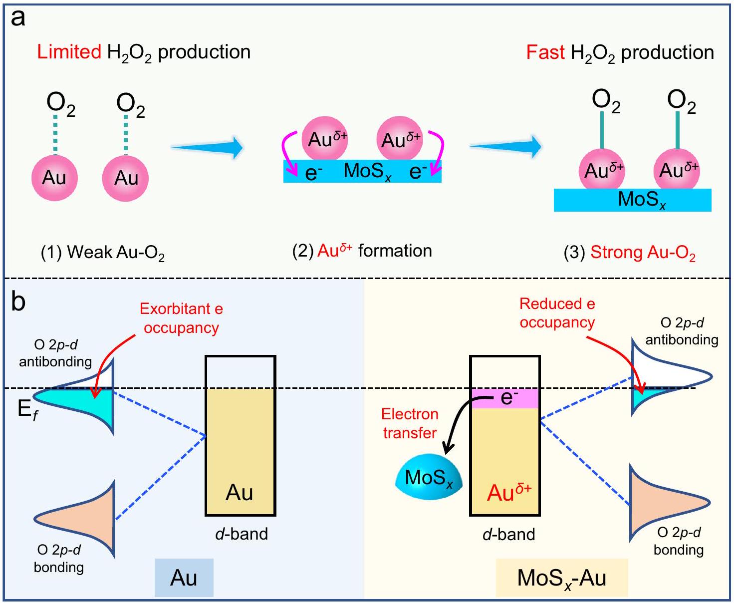
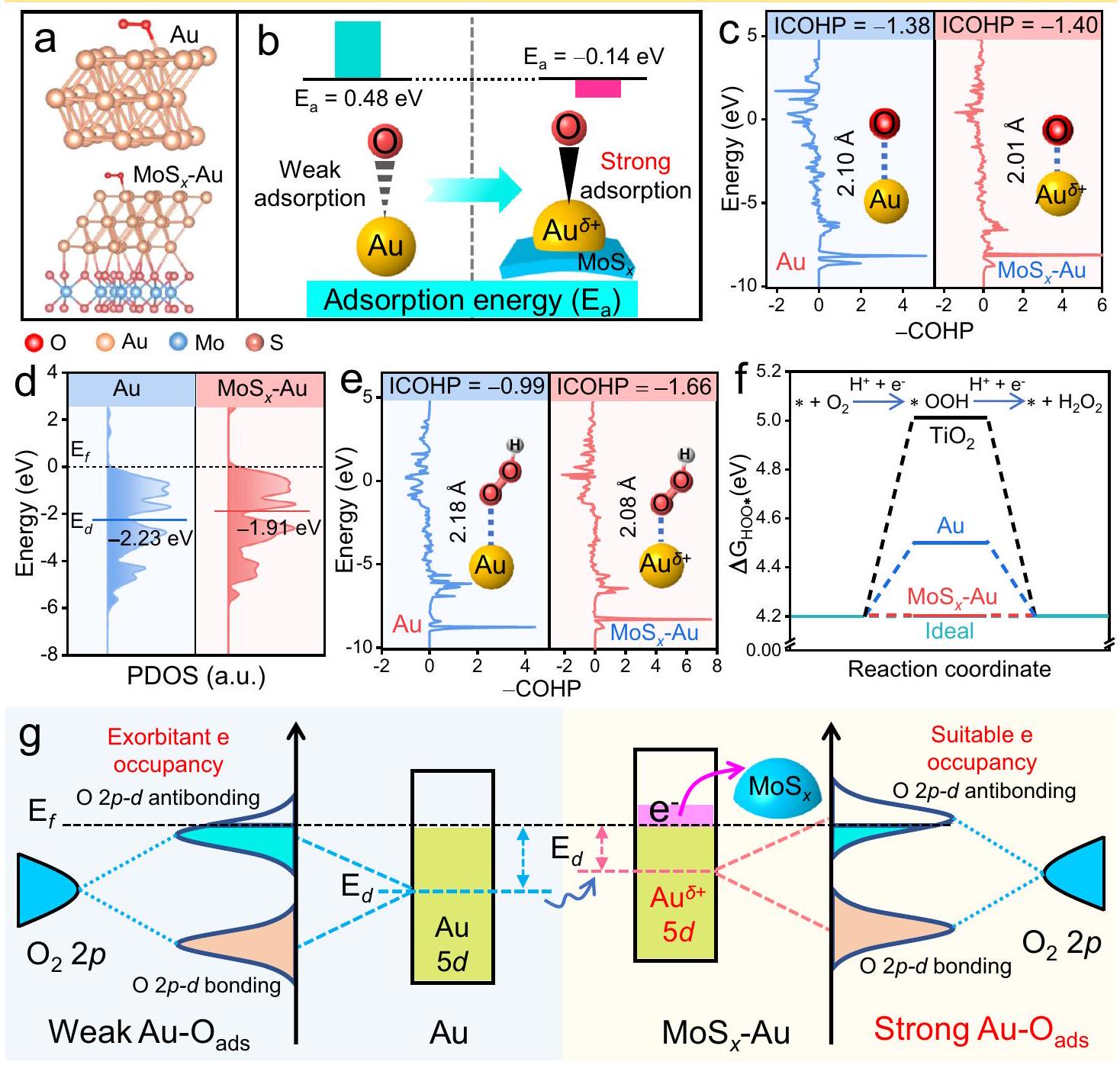
Gold-based co-catalysts are a promising class of materials with potential applications in photocatalytic production. However, current approaches with Au co-catalysts show limited production due to intrinsically weak adsorption at the Au site. We report an approach to strengthen adsorption at Au sites, and to improve production, through the formation of electron-deficient sites by modifying the electronic structure. In this case, we report the synthesis of , following selective deposition of Au onto a surface which is then further anchored onto . We further show that the catalyst achieves a significantly increased production rate of in -saturated solution containing ethanol. Density functional theory calculations and X-ray photoelectron spectroscopy analysis reveal that the mediator induces the formation of electron-deficient sites thereby decreasing the antibonding-orbital occupancy of and subsequently enhancing adsorption. This strategy may be useful for rationally designing the electronic structure of catalyst surfaces to facilitate artificial photosynthesis.

Solar-driven photocatalytic production through oxygen reduction reaction (ORR) is a promising method for addressing energy and environmental crises due to its low energy consumption, safety, and environmental friendliness . However, the production of via photocatalysts is hindered by the low efficiency of electron transfer and interface reaction , resulting in suboptimal yields . To address these challenges, cocatalyst deposition on the surface of photocatalysts can not only effectively promote electron transfer but also provide specialized active sites to facilitate interfacial . It is well known that photocatalytic production via ORR on the active sites of cocatalysts involves multiple fundamental steps, such as adsorption, intermediate * OOH formation, and desorption . Of these, adsorption at active sites is one of the most important processes, as it facilitates the formation of intermediate * OOH and its further conversion into . Sabatier principle . Suggests that
the interaction between active sites and adsorbates must have an optimal binding energy. Further research indicates that the electron configuration of active sites fundamentally determines their interaction with adsorbates, influencing their adsorption/desorption performances . However, in photocatalytic production, current cocatalysts usually suffer from a mismatch in the electronic configuration between the active site and the adsorbed , leading to either excessively strong or weak adsorption, which in turn limits production rates . Therefore, it is quite meaningful and challenging to modulate the electronic configuration of cocatalysts and optimize their oxygen adsorption strength to achieve efficient production.
Currently, noble metal cocatalysts ( , and Au ) have made significant advancements in improving photocatalytic ORR for production . Notably, Au cocatalysts usually exhibit a higher photocatalytic -production activity, attributed to the effective
interfacial charge transfer between photocatalysts and Au nanoparticles . This transfer enables the rapid movement of photogenerated electrons from the photocatalysts to the Au surface, facilitating the reduction of adsorbed to through either a two-step single-electron or a one-step two-electron ORR process . However, metallic Au usually exhibits weak oxygen adsorption characteristics due to its intrinsic electronic structure (Fig. 1a-(1)) , which limits the formation of the * OOH intermediate and subsequent production. Consequently, precise modulation of Au’s electronic structure is extremely crucial to optimize adsorption and enhance photocatalytic production. For instance, Tsukamoto et al. demonstrated increased electronic density in Au by forming an alloy, reducing decomposition on Au sites . Moreover, Wang et al. prepared an efficient core-shell -modified nanostructure. This structure reduces negative charge accumulation at the Au active sites by forming an ohmic contact with , thereby enhancing the adsorption of and its intermediate * OOH , leading to efficient photocatalytic -production performance . Although the introduction of alloy and bimetallic core-shell structures have efficiently enhanced the photocatalytic activity of Au sites, the relationship about the -production activity, the bonds, and the electronic structure of Au remains unclear. Fortunately, the molecular orbital theory clearly states that the antibonding-orbital occupancy degree between a metal and its adsorbate usually determines its adsorption energy , which provides a theoretical basis for the modulation of bond strength between Au and . Inspired by this,
selectively decreasing the antibonding-orbital occupancy of is expected to further enhance the adsorption on Au, potentially achieving efficient photocatalytic production. However, there has been limited research focusing on this approach to date.
In this work, we propose an approach to strengthen the bonds by modifying the electronic structure of Au active site. This is achieved through the introduction of molybdenum sulfide as an electron mediator to decrease the antibonding-orbital occupancy of Au-O . In this case, the mediator serves to adjust the electronic structure of Au cocatalyst, resulting in the creation of electrondeficient active sites and subsequently accelerating production (Fig. 1a-(2) and -(3)). To this end, -Au photocatalyst was synthesized by a two-step method. This process involves the initial deposition onto the surface and subsequent S -induced selective photodeposition of Au cocatalyst onto the surface. The resulting -Au photocatalyst achieves a boosted -production rate of , which is 25.4 and 1.3 times higher than and , respectively. Density functional theory (DFT) calculations and ex-situ X-ray photoelectron spectroscopy (XPS) analysis have confirmed the effective reduction of -orbital electron on Au cocatalyst upon the introduction of , leading to a decrease in antibonding-orbital occupancy in Au-O (Fig. 1b). Consequently, the bonds are significantly reinforced, which in turn enhances the rate of photocatalytic production. This work focuses on modifying the electron structure of Au cocatalyst to reduce the antibonding-orbital occupancy of Au-O , offering a promising
Fig. 1 | Strategy to design efficient electron-deficient cocatalyst for improving -production kinetics. a Schematic illustration of electrondeficient formation to reinforce bond: (1) weak bond on Au surface; (2) the formation of electron-deficient sites by incorporation; (3)
strong bond on -Au surface. Schematic diagram about reducing the antibonding-orbital occupancy of by the free-electron transfer from Au to cocatalyst.
Fig. 2 | Synthetic strategy and morphology characterization. a Schematic illustration for the synthesis of -Au by the initial lactic acid-induced deposition on the surface and subsequent S -induced selective
photodeposition of Au cocatalyst onto the surface. b, c TEM, d HRTEM, HAADF-STEM, and elemental mapping pictures of -Au photocatalyst.
approach to enhance adsorption for efficient photocatalytic production.

Results and discussion

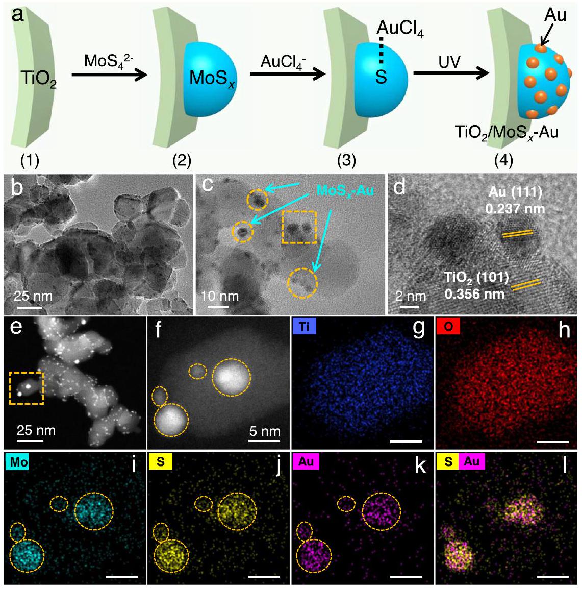
Synthesis and characterization of -Au

To realize the successful deposition of -Au cocatalyst on the surface of photocatalyst, a facile two-step route was carried out at room temperature (Fig. 2a), including the initial deposition of on the surface and the subsequently selective photodeposition of Au onto the surface (Supplementary Fig. 1). First, solution was mixed with a lactic acid solution to form brown colloidal nanoparticles (Supplementary Fig. 1a-(1)). Subsequently, nanoparticles were uniformly dispersed into this colloidal solution with constant stirring. The positive charge on the nanoparticles in the lactic acid solution allowed for the efficient adsorption of colloidal nanoparticles onto the surface via electrostatic selfassembly (Supplementary Fig. 1a-(2), c). The deposition of on the surface can be verified by Fourier transform infrared (FTIR) spectroscopy and Raman spectra analyses (Supplementary Fig. 2). A new FTIR peak for S-S vibration and a new Raman peak for Mo-S can be observed, providing strong evidence for the formation . With the further addition of solution into the suspension, ions can be selectively adsorbed onto the surface via the strong interaction between S and Au atoms (Fig. 2a) . Upon light irradiation, the ions were in situ reduced to form Au nanoparticles on the surface (Supplementary Figs. 1a-(3), d), evident from a color change from light brown to purple (Supplementary Fig. 1b), revealing the successful synthesis of
photocatalyst. The above result can further be supported by X-ray diffraction (XRD) and Raman spectra. Compared with the sample, a new XRD peak of Au at and an Au-S Raman peak confirm the selective deposition of Au nanoparticles on the surface (Supplementary Figs. 3 and 4).
Transmission electron microscopy (TEM) analysis was employed to further verify the selective deposition of Au on the surface within the -Au photocatalyst. As depicted in Fig. 2b-d, numerous dark spots on the surface are observed, which can be attributed to the -Au cocatalyst. The high-angle annular dark-field (HAADF) images (Fig. 2e, f) further indicate that the -Au nanoparticles were effectively deposited on the surface. The corresponding energy-dispersive X-ray spectroscopy (EDS) mapping images (Fig. 2g-l) show that four Au nanoparticles exhibit uniform and same distribution with the Mo and S elements on the particles, unequivocally indicating that all the Au nanoparticles are selectively deposited on the surface via the self-assembly of S-Au. Ultraviolet-visible absorption spectra (UV-Vis) demonstrate a typical surface plasmon resonance (SPR) absorption of Au (ca. 540 nm ) (Supplementary Fig. 5) , suggesting that Au was effectively deposited on the surfaces of both and . Noticeably, the SPR signal in the -Au appears relatively weaker than that of the , which can be attributed to the strong interaction between Au and S atoms. According to the inductively coupled plasma optical emission spectrometry (ICP-OES) results (Supplementary Table S1), the contents of Mo, S, and Au elements in the -Au photocatalyst are , and , respectively, indicating the presence of and Au in the -Au system. These results
Fig. 3 | Photocatalytic -production activities and stability. a Photocatalytic -production performance for different samples in an ethanol-water solution ( vol.): (1) , (2) , (3) , and (4) -Au. The error bars (mean standard deviation) were calculated based on three independent photocatalytic experiments. The AQY of production as a function of wavelength
on – Au (red dot), and the UV-vis absorbance spectrum (blue curve). The photocatalytic -production performance over (1) and (4) -Au in the -saturated and air condition. d Recycling -production performance of .
(HRTEM, UV-Vis, and ICP-OES) collectively support the selective deposition of Au on the surface.

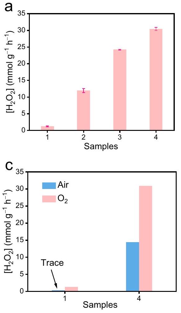
Photocatalytic performance

The photocatalytic activities for production were conducted in an -saturated ethanol solution under Xe lamp irradiation. As shown in Fig. 3a, exhibits a low -production rate of . However, the introduction of Au nanoparticles onto the surface leads to an improved -production rate ( ) for the resulting . With the further incorporation of cocatalyst into , the -Au shows a significant enhancement in the photocatalytic -production activity. Further investigation indicated that the -production activity of -Au photocatalysts is dependent on the Au amount (Supplementary Fig. 6). When the Au is precisely maintained at , the resulting sample exhibits the highest -production rate with a value of (Fig. 3a and Supplementary Fig. 6), which is 25.4 and 1.3 times higher than that of and , respectively. However, increasing the Au content beyond this point to leads to a reduction in yield due to the light-shielding effect. According to the wavelength-dependent -evolution activity (Fig. 3b), the AQY of -Au achieves an impressive value of at 365 nm . The present -evolution performance is much higher than most reported results in -based photocatalysts or other inorganic photocatalysts (Supplementary Table S2). To investigate the application potential of present -Au, its photocatalytic -evolution performance was further tested under different conditions. As exhibited in Fig. 3c and Supplementary Fig. 7, it is clear that there is almost no generation over in the air environment. In contrast, the yield in the -Au still maintains a high
concentration ( ), indicating the great application potential of the -Au photocatalyst. Besides, no significant decrease in the concentration is observed after four cycles of photocatalytic reaction (Fig. 3d), revealing the robust reusability of the . From the above results, it can be concluded that the introduction of mediator into can effectively improve the photocatalytic -production activity.

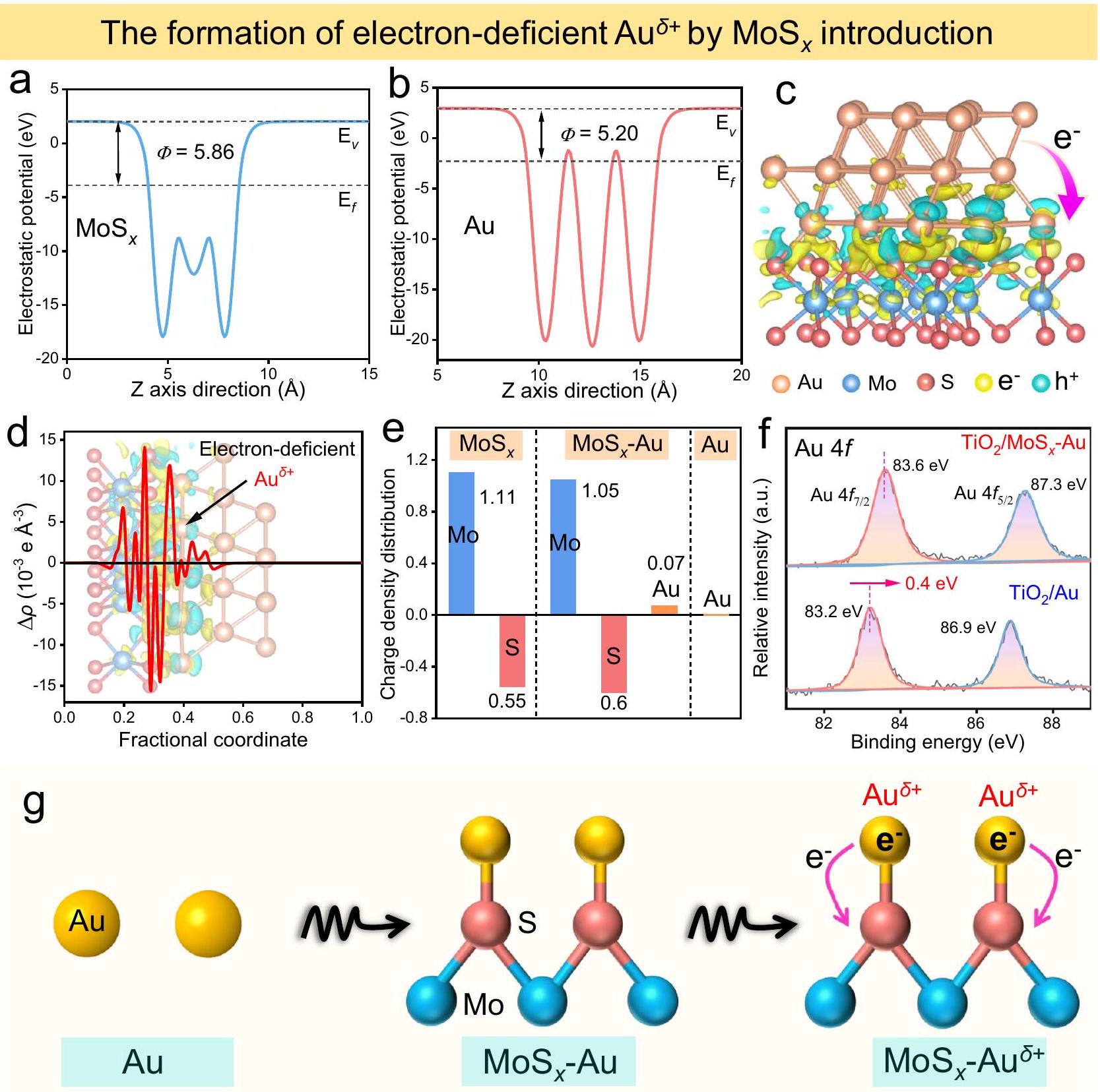
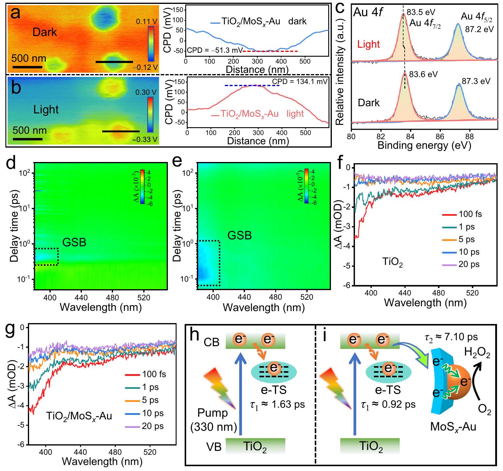
Photocatalytic mechanism of -Au

Considering the boosted -production activity, the effect of the mediator on the Au electronic structure is primarily investigated by the first-principles calculations and XPS technology. For comparison, three slab models of , and -Au are reasonably selected and optimized (Supplementary Fig. 8). Based on the optimized models, the work functions ( ) of (001) and Au (111) are calculated to be 5.86 and 5.20 eV , respectively (Fig. 4a, b). In this case, when Au is loaded onto the surface, free electrons would migrate inevitably from Au nanoparticles to (Supplementary Fig. 9) , thus inducing the formation of electron-deficient sites. This electron transfer is further substantiated by examining the local charge density difference and the corresponding planar-averaged electron density difference (Fig. 4c, d) . Obviously, the -Au cocatalyst shows a distinct electron-enriched region on the side, while positive charges predominantly accumulate on Au atoms, leading to the production of an electron-deficient layer (Fig. 4d). To quantify the above charge transfer between Au and MoS , Bader charge calculation was performed and shown in Fig. 4e. Clearly, they indicate a more negative charge density for S and Mo atoms in -Au compared to pure . Conversely, the charge density of Au atoms is slightly increased (+0.07) to produce active sites in the – Au
Fig. -induced electron-deficient formation and mechanism. Calculated average potential profiles of and Au. c The local charge density difference of , where the light yellow and cyan areas represent electron accumulation and depletion, respectively. d Planar-averaged electron density
difference in -Au. e The charge density distributions of , and Au. f High-resolution XPS spectra of in the and . Schematic illustration of the formation of electron-deficient sites in the -Au cocatalyst.
cocatalyst. The formation of above electron-deficient can further be verified by XPS analysis (Fig. 4f). Compared with the , a clear shift of binding energy (from 83.2 to ) to a higher value is observed for in the -Au. In addition, the XPS peaks of and Mo shift to lower values ( for for ) than those of (Supplementary Fig. 10), indicating the efficient electron transfer from Au to . The above electron transfer can also cause a slight change of binding energy for the Ti element (Supplementary Fig. 11). Unquestionably, both DFT calculation and experimental results strongly support that the introduction of mediator can effectively modulate the Au electronic structure to induce the formation of electron-deficient sites in the -Au cocatalyst (Fig. 4 g ).
The generation of electron-deficient impacts the adsorption capability of -Au photocatalyst, as evidenced by various analyses: adsorption energy, crystal orbital Hamilton population (COHP), bonding distance analysis, and partial density of states (PDOS) calculations. Based on the optimized models in Fig. 5a and Supplementary Fig. 12, the adsorption energies ( ) of Au sites before and after introduction were first calculated (Fig. 5b). Clearly, the electron-deficient sites in the -Au cocatalyst exhibit more negative adsorption energy ( ) than pure , indicating stronger adsorption capability . Further evidence of this enhanced adsorption is provided by COHP calculations , revealing a smaller integrated COHP value (-1.40) for bonds in than in pure , and shorter bond length ( ) compared to pure , signifying
The enhanced adsorption on electron-deficient site
Fig. 5 | Modifying the electron structure of Au cocatalyst to decrease the antibonding-orbital occupancy of Au-O ads for enhancing Au-O ads bonds. a Optimized configurations for adsorption on Au and , and the corresponding adsorption energies and schematic illustration about the improved adsorption ability. c COHP analyses of adsorption on Au and -Au. d PDOS
diagrams of Au 5d orbitals in Au and MoS -Au. e COHP analyses of OOH adsorption on Au and ( represents active site). over and . g Schematic diagram about the enhanced adsorption on Au sites by decreasing antibonding-orbital occupancy via raising its -band center.
stronger bonding in electron-deficient sites (Fig. 5c) . In this case, the -band center mechanism helps explain this enhanced bonding in the . As depicted in Fig. 5d, g , the -band center of Au in pure Au cocatalyst is -2.23 eV , significantly far away from . Consequently, the lower -band center causes exorbitant antibonding-orbital occupancy, leading to a weak Au-O bond. However, when Au is loaded on the surface, the resulting -band center of in the – Au is closer to the than that of pure Au suggesting that modulating the electron structure of the Au cocatalyst to form electron-deficient sites can significantly elevate the -band center (Fig. 5 g ). In this case, when is adsorbed on the electrondeficient sites, the antibonding-orbital occupancy of is decreased, resulting in a reinforced adsorption. Therefore, the presence of cocatalyst in the -Au can effectively raise the -band center of sites for improved adsorption, which is one of the essential steps for the following production.
It is worth emphasizing that a suitable bond can effectively contribute to the formation of intermediate, thus
greatly improving the selectivity and activity of photocatalytic production (Supplementary Fig. 13). Hence, to explore the effect of improved bonds on the formation of intermediate in -Au cocatalyst, COHP calculation was carried out. As illustrated in Fig. 5e, both COHP value ( -1.66 ) and bond length ( , inset) of in -Au are smaller than those in pure Au (-0.99 and ), forcefully manifesting that the -Au possess stronger Au bonds, which is beneficial to improving the selectivity of photocatalytic production. The above selectivity and activity of photocatalytic production on -Au cocatalyst can further be confirmed by the free energy of intermediate ( ) based on the optimized models in Supplementary Fig. . As shown in Fig. 5f, the values on and Au sites are estimated to be 5.01 and 4.5 eV , respectively, which are significantly higher than the ideal value . These results suggest that and Au have relatively weak adsorption and easier detachment for *OOH intermediates, leading to sluggish interfacial -production kinetics (Supplementary Fig. 13a). In contrast, the electron-deficient sites
The photogenerated electron transfer from to cocatalyst
Fig. 6 | Photogenerated electron transfer mechanism and dynamics. a, b KPFM images and the corresponding surface potential profiles of the – Au in the dark and light illumination, a 365 nm -LED light as the light source. c ISI-XPS spectra of for -Au before and after light illumination. Pseudocolor plots of d and -Au (GSB represents ground-state bleaching).
Femtosecond transient absorption spectra of and -Au within 20 ps . All data were obtained under excitation of 330 nm and optical power of 600 . Schematic illustration of the decay pathways of photogenerated electrons in and .
in the -Au cocatalyst showcase the best values ( 4.2 eV ), aligning with the ideal energy for *OOH adsorption and facilitating rapid generation (Supplementary Fig. 13b).
In addition to enhancing adsorption for efficient production, the -Au cocatalyst also promotes the rapid transfer of photogenerated electrons in the -Au photocatalyst, which is supported by the subsequent Kelvin probe force microscopy (KPFM) and in situ XPS . A scanning probe microscopy (SPM) system with KPFM was employed to analyze the distribution and transfer pathways of photogenerated electron-hole pairs in photocatalysts. The resulting AFM topography image, KPFM image, and the corresponding contact potential difference (CPD) profiles of and -Au are shown in Fig. 6a, b, and Supplementary
Figs. 15 and 16. Obviously, the -Au particles are observed, and a line scan across the above sample pre- and post-light irradiation is used to evaluate the CPD change. Upon light irradiation, the CPD value of shows a slight increase from -14.7 to 8.6 mV owing to the spontaneous transfer of photogenerated holes onto the surface (Supplementary Fig. 16) . After the loading of -Au, the -Au exhibits an obvious CPD value increase of about 185.4 mV (from -51.3 to 134.1 mV ) during light irradiation, accompanied by a color change from blue to red owing to enhanced hole accumulation on the surface (Fig. 6a, b), strongly indicating that the photogenerated electrons are efficiently transferred from to -Au cocatalyst . To further validate the above transfer of photogenerated electrons and their enrichment on the Au active sites of
, in situ XPS was performed (Fig. 6c). The peaks of Au and in the -Au are remarkably shift toward lower binding energies (from 83.6 eV to ) upon light irradiation, suggesting that the photogenerated electrons are directionally transferred from to -Au and mainly enriched on the electron-deficient sites, thereby promoting the photocatalytic -production kinetics .
For a comprehensive understanding of electron-transfer dynamics in the -Au, femtosecond transient absorption spectroscopy (fs-TAS) was carefully performed . As shown in Fig. 6d, e and Supplementary Fig. 17a, a typical photobleaching peak ( -380 nm ) is displayed in the pseudocolor plots of , and Au. These signals are assigned to the ground-state bleaching (GSB), which reflects the excited state relaxation . Further monitoring of the GSB signal ( 380 nm ) within 20 ps reveals stronger intensity in the Au (Supplementary Fig. 17b) and -Au (Fig. 6 g ) compared to (Fig. 6f), indicating enhanced electron enrichment in both Au and . Further analysis of the interfacial electron transfer involved fitting decay kinetics within 25 ps at 380 nm using biexponential equations, with fitting results of normalized curves shown in Supplementary Fig. 18 and Table S3. The short-lived corresponds to the electron trapping by electron trapping state (e-TS), while the long-lived is related to the interfacial electron transfer from to cocatalyst. Meanwhile, and represent the decay proportion of photogenerated electrons during the electron trapping and transfer, respectively. Obviously, the primarily undergoes a short-lived process within 25 ps under irradiation, and the corresponding is 1.63 ps , which is primarily attributed to electron trapping in the e-TS (Fig. 6h). Interestingly, the value in the and -Au significantly decreases to 0.36 and 0.92 ps , respectively, suggesting rapid transfer of a portion of photogenerated electrons from to and cocatalysts (Fig. 6i). Noticeably, the -Au exhibits a larger value ( ) compared to the , indicating more effective transfer of photogenerated electrons from to Au facilitated by the mediator . The improved electron transfer on is well consistent with the results of photoelectrochemical and transient-state photoluminescence (TRPL) (Supplementary Fig. 19). These above results provide concertedly evidence that the -Au cocatalyst serves as an efficient platform for rapid transfer of photogenerated electrons to engage in the subsequent -production reaction at the electron-deficient sites (Fig. 6i), thus achieving high photocatalytic yields.
Overall, a strategy of electronic structure modification for the Au cocatalyst has been proposed to effectively reinforce the bonding at electron-deficient sites within the -Au cocatalyst, which can achieve an enhanced adsorption for fast production kinetics. As a result, an exceptional -production rate of has been achieved in the resulting Au , which is 25.4 and 1.3 times higher than that of and , respectively. Theoretical simulations and experimental results consistently support the notion that the introduction of mediator induces the formation of electron-deficient active sites in the -Au cocatalyst by free-electron transfer from the Au cocatalyst to , which decreases the antibonding-orbital occupancy of the Au- , thereby enhancing the -adsorption ability to realize efficient -production performance. In addition, the -Au cocatalyst can also provide an efficient platform for the rapid transfer and enrichment of photogenerated electrons from , leading to a distinct improvement of photocatalytic -production activity for the -Au. This work emphasizes a feasible strategy for optimizing the -adsorption strength to efficiently accelerate production kinetics, offering a very promising approach for the rational design of electronic structure for efficient artificial photosynthesis.

Methods

Preparation of photocatalyst

photocatalyst (P25) was calcined at for 2 h in a muffle furnace before being used. The sample was synthesized by one-step lactic acid-induced method, as schematically demonstrated in Supplementary Fig. 1. First, solution was dropped into 160 mL lactic acid solution ( ) under stirring. In this case, the was released from lactic acid and would induce the transformation of into colloidal nanoparticles. Subsequently, the as-prepared nanoparticles ( 0.1 g ) were dispersed into the above solution. After stirring for 2 h , a brown product was collected by centrifugation and washing with deionized water and ethanol. Finally, the obtained product was dried at for 12 h . The resulting brown powder was denoted as . In addition, the pure product was also obtained by a similar synthesis route of the above in the absence of .

Preparation of -Au photocatalyst

The -Au modified photocatalyst ( ) was synthesized by a two-step route, including the initial deposition of on the surface and the subsequently selective photodeposition of Au onto the surface. First, 0.1 g of the was mixed with 80 mL ethanol aqueous solution ( ) in a 100 mL three-necked flask. Then, a known amount of chloroauric acid ( , ) was added. After the above system was evacuated with for 20 min and then irradiated with a 300 W Xenon lamp for 1 h , the resultant suspension was collected by centrifugated, rinsed, and dried at for 12 h to obtain the final . To investigate the effect of Au amount on the structure and photocatalytic performance, the amount of Au in the was controlled to be , and , respectively, and the resultant sample was referred to be ( is the amount of Au ).

Preparation of Au photocatalyst

Au nanoparticle-loaded was prepared by a photodeposition method. First, 0.1 g of the was dispersed into a 100 mL of ethanol aqueous solution ( ). Subsequently, a known amount of chloroauric acid ( ) was added dropwise to the above mixture solution. Before irradiation, the above system was bubbled with for 20 min and then irradiated for 1 h . Finally, a lightpurple product was collected by centrifugated, rinsed, and dried at for 12 h . The resulting powder was denoted as .

Characterization

The microstructure of the samples was characterized by transmission electron microscopy (TEM; Thermal Fisher Talos F200X). X-ray photoelectron spectroscopy (XPS) was performed on a Thermo Scientific ESCALA 210 XPS spectrometer system (USA) with 300 W Al K radiation to survey the elemental composition and valence states of these photocatalysts. The X-ray diffraction (XRD) patterns of the samples were obtained on an X-ray diffractometer (Shimadzu XRD-6100) with radiation. The elemental content was performed by inductively coupled plasma optical emission spectrometry (ICP-OES). The ultraviolet-visible spectra (UV-vis DRS) were obtained on a UV-vis spectrophotometer (UV-2600i, Shimadzu, Japan). Time-resolved photoluminescence (TRPL) spectra were acquired on a fluorescence lifetime spectrophotometer (FLS 1000, Edinburgh, UK). The photoirradiated Kelvin probe force microscopy (KPFM) (SPM-9700, Shimadzu, Japan) was carried out to test the contact potential difference of the samples.

Photocatalytic production test

Photocatalytic -production activity was examined in an -saturated aqueous solution with ethanol as a hole scavenger, and a 300 W Xenon arc lamp was selected as the light source. First, 10 mg of
as-prepared photocatalyst and 100 mL of ethanol solution ( ) were mixed in a 100 mL three-necked flask reactor. Before irradiation, the system was purged with oxygen for 30 min to obtain an -saturated solution. During the photocatalytic -production test, 1 mL of solution was sampled from the reactor. Finally, the concentration was examined via an iodometry method by using a UVvisible spectrophotometer (UV-1240, Japan). The concentration of was calculated by the equation ( ), and the reaction mechanism was shown in Eq. (1). The absorbance of at 350 nm can be recorded by UV-vis spectroscopy.

Photoelectrochemical measurements

The photoelectrochemical (PEC) properties were assessed using an electrochemical workstation (CHI 760E, China) within a threeelectrode system. The working electrode was prepared by applying the photocatalyst onto a FTO glass substrate. The (in a saturated KCl solution) and Pt foil were designated as the reference and counter electrodes, respectively. The PEC assessments were carried out in a solution using a 300 W Xenon arc lamp for illumination.

Average decay time ( ) calculation

The decay curves of as-prepared samples from the TRPL can be effectively fitted using the following biexponential Eq. (2), and the fluorescent lifetime ( ) is calculated by Eq. (3).
where and represent the weight factors, while and are the short and long fluorescent lifetimes, respectively.

Apparent quantum yield (AQY) calculation

The AQY measurement was conducted in an -saturated aqueous solution with ethanol as a hole scavenger by utilizing a 300 W Xenon arc lamp as the light source. In detail, the as-prepared photocatalyst ( 10 mg ) and ethanol solution ( ) were mixed in a 100 mL three-necked flask reactor, which was oxygenated for 30 min to obtain the -saturated solution.
The apparent quantum yields for were calculated from the following Eq. (4):
where represents the amount of produced molecules (mol), is the Avogadro constant ( ), is the Planck constant is the speed of light is the irradiation area ( ), is the average intensity of irradiation ( 365 nm , is the irradiation time ( s ), and is the wavelength of the incident monochromatic light ( nm ).

Ultrafast transient absorption (TA) tests

Femtosecond transient absorption spectra of the as-prepared photocatalysts were obtained on a pump-probe system (Helios, Ultrafast System) with a maximum time delay of using a motorized optical delay line under ambient conditions. The 330 nm -pump pulses ( 600 average at tested samples) were generated by the 1 kHz regenerative amplifier (Coherent Libra, ) in an optical parametric amplifier (OPerA Solo), seeded with a mode-locked Ti:
sapphire oscillator (Coherent Vitara, ) and pumped with an LBO laser (Coherent Evolution-50C, 1 kHz system). To generate the white light from 320 to 750 nm , the 800 nm -femtosecond pluses were pumped by a constantly rotating sapphire crystal.

Computational details

The density functional theory (DFT) calculations were performed using the Vienna Ab initio Simulation Package (VASP) with the generalized gradient approximation (GGA) employing the revised Perdew-Burke-Ernzerhof (PBE) functional for the exchangecorrelation interaction. The convergence threshold for total energy converged within atom , and the average force was . Grid integration utilized a cutoff energy of 450 eV , and projectoraugmented wave (PAW) potentials characterized the ion cores. To rationalize the calculation, unsaturated sulfur (S) atoms were obtained on the edge of model by creating a vacuum layer in the -axis direction, which displayed a similar local coordination structure as amorphous cocatalyst. Moreover, Monkhorst-Pack grids and ( ) surface cells were used for oxygen adsorption. The adsorption energy was defined as , where , and represent the energy of adsorption configurations, the energy of metallic surfaces, and the energy of molecular , respectively. In addition, the of HOO* intermediate on the surface was calculated by the equation , where is the total energy, is the zero-point energy, is the temperature ( 298.15 K ), and is the entropy. Several configurations of the adsorbed models were considered in the simulation, and the most favorable ones are presented based on the adsorption energy.

Data availability

Data is available from the authors on request. All data generated in this study are provided in the Source data file. Source data are provided with this paper.

References

  1. Zhao, Y. et al. Mechanistic analysis of multiple processes controlling solar-driven synthesis using engineered polymeric carbon nitride. Nat. Commun. 12, 3701 (2021).
  2. Teng, Z. et al. Atomically dispersed antimony on carbon nitride for the artificial photosynthesis of hydrogen peroxide. Nat. Catal. 4, 374-384 (2021).
  3. Liu, T. et al. Overall photosynthesis of by an inorganic semiconductor. Nat. Commun. 13, 1034 (2022).
  4. Zhang, Y. et al. generation from and on a near-infrared absorbing porphyrin supramolecular photocatalyst. Nat. Energy 8, 361-371 (2023).
  5. Zhang, X. et al. S-scheme heterojunction of core-shell biphase (1T nanorod arrays for enhanced photoelectrocatalytic production of hydrogen peroxide. Chem. Eng. J. 429, 131312 (2022).
  6. He, Q. et al. Multiscale structural engineering of carbon nitride for enhanced photocatalytic production. Nano. Res. 16, 4524-4530 (2021).
  7. Yang, Y. et al. Molecular engineering of polymeric carbon nitride for highly efficient photocatalytic oxytetracycline degradation and production. Appl. Catal. B Environ. 272, 118970 (2020).
  8. Hou, H., Zeng, X. & Zhang, X. Production of hydrogen peroxide by photocatalytic processes. Angew. Chem. Int. Ed. 59, 17356-17376 (2020).
  9. Wang, L. et al. Inorganic metal-oxide photocatalyst for production. Small 18, 2104561 (2021).
  10. Zhang, J. et al. The critical role of furfural alcohol in photocatalytic production on TiO2. Appl. Catal. B Environ. 269, 118770 (2020).
  11. Song, S. et al. Structure effect of graphene on the photocatalytic performance of plasmonic -rGO for photocatalytic elimination of pollutants. Appl. Catal. B Environ. 181, 71-78 (2016).
  12. Lin, Z. et al. Apparent potential difference boosting directional electron transfer for full solar spectrum-irradiated catalytic evolution. Adv. Funct. Mater. 30, 1908797 (2019).
  13. Li, K., Zhang, S., Li, Y., Fan, J. & Lv, K. MXenes as noble-metalalternative co-catalysts in photocatalysis. Chin. J. Catal. 42, 3-14 (2021).
  14. Chu, C. et al. Electronic tuning of metal nanoparticles for highly efficient photocatalytic hydrogen peroxide production. ACS Catal 9, 626-631 (2018).
  15. Zhang, . et al. PDA -Scheme heterojunction with enhanced photocatalytic production performance and its mechanism. Adv. Sustain. Syst. 7, 2200113 (2023).
  16. Zhang, Y., Liang, C., Feng, H. & Liu, W. Nickel single atoms anchored on ultrathin carbon nitride for selective hydrogen peroxide generation with enhanced photocatalytic activity. Chem. Eng. J. 446, 137379 (2022).
  17. Teng, Z. et al. Photoexcited single metal atom catalysts for heterogeneous photocatalytic production: Pragmatic guidelines for predicting charge separation. Appl. Catal. B Environ. 282, 119589 (2021).
  18. Choi, C. et al. Hydrogen peroxide synthesis via enhanced twoelectron oxygen reduction pathway on carbon-coated Pt surface. J. Phys. Chem. C 118, 30063-30070 (2014).
  19. Yang, Y. et al. Bifunctional -scheme photocatalyst with enhanced production and furoic acid synthesis mechanism. Appl. Catal. B Environ. 333, 122780 (2023).
  20. Koper, M. & Bouwman, E. Electrochemical hydrogen production: bridging homogeneous and heterogeneous catalysis. Angew. Chem. Int. Ed. 49, 3723-3725 (2010).
  21. Gao, D., Long, H., Wang, X., Yu, J. & Yu, H. Tailoring antibondingorbital occupancy state of selenium in Se-enriched ReSe cocatalyst for exceptional evolution of photocatalyst. Adv. Funct. Mater. 33, 2209994 (2023).
  22. Wang, K. et al. Optimizing oxygen and intermediate adsorption of Cu-Pd alloy cocatalyst for boosting photocatalytic production of . Adv. Sustain. Syst. 6, 2200144 (2022).
  23. . et al. Palladium-copper nanodot as novel -evolution cocatalyst: optimizing interfacial hydrogen desorption for highly efficient photocatalytic activity. Chin. J. Catal. 43, 215-225 (2022).
  24. Shi, H. et al. Mass-transfer control for selective deposition of welldispersed AuPd cocatalysts to boost photocatalytic production of . Chem. Eng. J. 443, 136429 (2022).
  25. Fuku, K. et al. Photocatalytic production from under visible light irradiation over phosphate ion-coated Pd nanoparticlessupported . Appl. Catal. B Environ. 272, 119003 (2020).
  26. Teranishi, M., Naya, S. & Tada, H. In situ liquid phase synthesis of hydrogen peroxide from molecular oxygen using gold nanoparticle-loaded titanium(IV) dioxide photocatalyst. J. Am. Chem. Soc. 132, 7850-7851 (2010).
  27. Hirakawa, H. et al. Au nanoparticles supported on : effective inorganic photocatalysts for production from water and under visible light. ACS Catal 6, 4976-4982 (2016).
  28. Kobayashi, H., Teranishi, M., Negishi, R., Naya, S. & Tada, H. Reaction mechanism of the multiple-electron oxygen reduction reaction on the surfaces of gold and platinum nanoparticles loaded on titanium(IV) oxide. J. Phys. Chem. Lett. 7, 5002-5007 (2016).
  29. Wang, Y. et al. Efficient production of on under visible light and the influencing factors. Appl. Catal. B Environ. 284, 119691 (2021).
  30. Zuo, G. et al. Finely dispersed Au nanoparticles on graphitic carbon nitride as highly active photocatalyst for hydrogen peroxide production. Catal. Commun. 123, 69-72 (2019).
  31. Kim, K. et al. Solid-phase photocatalysts: physical vapor deposition of Au nanoislands on porous films for millimolar production within a few minutes. ACS Catal 9, 9206-9211 (2019).
  32. An, R. et al. Decoration of Au NPs on hollow structured BiOBr with surface oxygen vacancies for enhanced visible light photocatalytic evolution. J. Solid State Chem. 306, 122722 (2022).
  33. Liu, Z., Gong, X., Kohanoff, J., Sanchez, C. & Hu, P. Catalytic role of metal oxides in gold-based catalysts: a first principles study of CO oxidation on supported Au. Phys. Rev. Lett. 91, 266102 (2003).
  34. Li, L. et al. Tailoring selectivity of electrochemical hydrogen peroxide generation by tunable pyrrolic-nitrogen-carbon. Adv. Energy Mater. 10, 2000789 (2020).
  35. Tsukamoto, D. et al. Photocatalytic production from ethanol/ system using loaded with Au-Ag bimetallic alloy nanoparticles. ACS Catal 2, 599-603 (2012).
  36. Wang, K. et al. Microparticles decorated with coreshell nanostructures for photocatalytic production. ACS Appl. Nano Mater. 4, 13158-13166 (2021).
  37. Men, Y. et al. Oxygen-inserted top-surface layers of Ni for boosting alkaline hydrogen oxidation electrocatalysis. J. Am. Chem. Soc. 144, 12661-12672 (2022).
  38. Yadav, V. et al. Modulating the structure and hydrogen evolution reactivity of metal chalcogenide complexes through ligand exchange onto colloidal Au nanoparticles. ACS Catal 10, 13305-13313 (2020).
  39. Gao, D. et al. Reversing free-electron transfer of cocatalyst for optimizing antibonding-orbital occupancy enables high photocatalytic evolution. Angew. Chem. Int. Ed. 62, e202304559 (2023).
  40. Gao, D. et al. Optimizing atomic hydrogen desorption of sulfur-rich cocatalyst for boosting photocatalytic evolution. Adv. Mater. 34, 2108475 (2022).
  41. Castelló, L. et al. Nano-gold decorated ZnO : an alternative photocatalyst promising for degradation. Chem. Eng. Sci. 267, 118377 (2023).
  42. Inagaki, M., Motobayashi, K. & Ikeda, K. In situ surface-enhanced electronic and vibrational Raman scattering spectroscopy at metal/ molecule interfaces. Nanoscale 12, 22988-22994 (2020).
  43. Liu, Q. et al. Unraveling the roles of hot electrons and cocatalyst toward broad spectrum photocatalytic generation of nanotube. Sol. RRL 5, 2000504 (2021).
  44. Zhong, W. et al. Novel core-shell Ag@AgSe nanoparticle co-catalyst: in situ surface selenization for efficient photocatalytic production of . Chin. J. Catal. 43, 1074-1083 (2022).
  45. Tao, J. et al. A novel CoP@AAH cocatalyst leads to excellent stability and enhanced photocatalytic evolution of CdS by structurally separating the photogenerated carriers. Appl. Catal. B Environ. 32O, 122004 (2023).
  46. Yue, X., Cheng, L., Fan, J. & Xiang, Q. 2D/2D BiVO4 S-scheme heterojunction for photocatalytic reduction: Insights into structure regulation and Fermi level modulation. Appl. Catal. B Environ. 304, 120979 (2022).
  47. Zhong, W., Zhao, B., Wang, X., Wang, P. & Yu, H. Synchronously enhancing water adsorption and strengthening bonds in Se-rich cocatalyst for efficient alkaline photocatalytic production. ACS Catal 13, 749-756 (2023).
  48. Yang, C., Wan, S., Zhu, B., Yu, J. & Cao, S. Calcination-regulated microstructures of donor-acceptor polymers towards enhanced and stable photocatalytic production in pure water. Angew. Chem. Int. Ed. 134, e202208438 (2022).
  49. Li, K., Blatov, V. & Wang, J. Discovery of electrides in electron-rich Non-electride materials via energy modification of interstitial electrons. Adv. Funct. Mater. 32, 2112198 (2022).
  50. Zhang, X. et al. Optimizing the Pd sites in pure metallic aerogels for efficient electrocatalytic production. Adv. Mater. 35, 2211512 (2023).
  51. Zhong, W. et al. Charging d-orbital electron of cocatalyst enables splendid alkaline photocatalytic evolution. Adv. Funct. Mater. 33, 2302325 (2023).
  52. Wang, J. et al. Cooperative coupling of photocatalytic production of and oxidation of organic pollutants over gadolinium ion doped nanocomposite. Chin. Chem. Lett. 34, 108157 (2023).
  53. Li, F. et al. Understanding the unique S-scheme charge migration in triazine/heptazine crystalline carbon nitride homojunction. Nat. Commun. 14, 3901 (2023).
  54. Zhao, M. et al. A novel S-scheme 3D heterostructure for improved hydrogen production under visible light irradiation. Chin. J. Catal. 43, 2615-2624 (2022).
  55. Chen, R., Fan, F., Dittrich, T. & Li, C. Imaging photogenerated charge carriers on surfaces and interfaces of photocatalysts with surface photovoltage microscopy. Chem. Soc. Rev. 47, 8238-8262 (2018).
  56. Chen, R. et al. Charge separation via asymmetric illumination in photocatalytic particles. Nat. Energy 3, 655-663 (2018).
  57. Gu, M. et al. Efficient sacrificial-agent-free solar production over all-inorganic S-scheme composites. Appl. Catal. B Environ. 324, 122227 (2023).
  58. He, B. et al. Cooperative coupling of production and organic synthesis over a floatable polystyrene-sphere-supported S-Scheme photocatalyst. Adv. Mater. 34, 2203225 (2022).
  59. Cheng, C. et al. Verifying the charge-transfer mechanism in SScheme heterojunctions using femtosecond transient absorption spectroscopy. Angew. Chem. Int. Ed. 135, e202218688 (2023).
  60. Wang, L. et al. Dynamics of photogenerated charge carriers in inorganic/organic S-Scheme heterojunctions. J. Phys. Chem. Lett. 13, 4695-4700 (2022).

Acknowledgements

This work was supported by the National Natural Science Foundation of China (22278324 (J.Y.), 52073223 (J.Y.), U22A20147 (H.Y.) and 22261142666 (J.Y.)) and the Natural Science Foundation of Hubei Province of China (2022CFA001 (H.Y.)). We thank the Faculty of Materials Science and Chemistry, China University of Geosciences (CUG), Wuhan for its TEM facilities and the data analysis of Dr. Mingxing Gong.

Author contributions

X.Z., D.G., and H.Y. conceived and designed the experiments. X.Z., D.G., and B.Z. carried out the synthesis, characterizations, and theory
calculations of the materials. X.Z. and D.G. carried out the photocatalytic test. X.Z., B.C., J.Y., and H.Y. contributed to data analysis. J.Y. and H.Y. supervised the project. X.Z. and H.Y. wrote the manuscript. B.C., J.Y., and H.Y. revised and reviewed the manuscript. All authors discussed the results and commented on the manuscript.

Competing interests

The authors declare no competing interests.

Additional information

Supplementary information The online version contains
supplementary material available at
https://doi.org/10.1038/s41467-024-47624-7.
Correspondence and requests for materials should be addressed to Huogen Yu.
Peer review information Nature Communications thanks the anonymous reviewers for their contribution to the peer review of this work. A peer review file is available.
Reprints and permissions information is available at
http://www.nature.com/reprints
Publisher’s note Springer Nature remains neutral with regard to jurisdictional claims in published maps and institutional affiliations.
Open Access This article is licensed under a Creative Commons Attribution 4.0 International License, which permits use, sharing, adaptation, distribution and reproduction in any medium or format, as long as you give appropriate credit to the original author(s) and the source, provide a link to the Creative Commons licence, and indicate if changes were made. The images or other third party material in this article are included in the article’s Creative Commons licence, unless indicated otherwise in a credit line to the material. If material is not included in the article’s Creative Commons licence and your intended use is not permitted by statutory regulation or exceeds the permitted use, you will need to obtain permission directly from the copyright holder. To view a copy of this licence, visit http://creativecommons.org/ licenses/by/4.0/.
(c) The Author(s) 2024

  1. Laboratory of Solar Fuel, Faculty of Materials Science and Chemistry, China University of Geosciences, 68 Jincheng Street, Wuhan, P. R. China. State Key Laboratory of Silicate Materials for Architectures, Wuhan University of Technology, 122 Luoshi Road, Wuhan, P. R. China. State Key Laboratory of Advanced Technology for Material Synthesis and Processing, Wuhan University of Technology, Wuhan, P. R. China. e-mail: yuhuogen@cug.edu.cn