تفاعل تطور الهيدروجين المستقر عند كثافات تيار عالية من خلال تصميم ذرات النيكل المفردة وجزيئات الروثينيوم النانوية المرتبطة بواسطة جسور كربونية Stable hydrogen evolution reaction at high current densities via designing the Ni single atoms and Ru nanoparticles linked by carbon bridges
لا يزال التطور المستمر والفعال للهيدروجين تحت كثافات تيار عالية يمثل تحديًا لعملية التحليل الكهربائي للماء بسبب التدهور السريع في الأداء تحت التشغيل المستمر للتيار الكبير. في هذه الدراسة، تؤكد الحسابات النظرية، وطيف رامان أثناء التشغيل، وتجارب إزالة CO أن البلورات النانوية من الروثينيوم تتمتع بمقاومة عالية ضد التوقف بسبب الامتزاز التآزري للوسائط OH.على الروديوم والذرات الفردية. استنادًا إلى هذا النموذج المفاهيمي، نقوم بتصميم ذرات النيكل الفردية عن طريق تعديل جزيئات الروديوم النانوية فائقة الصغر بهيكل كربوني جسر عيب (UP-RuNis) ) من خلال استراتيجية ترسيب كهربائي أحادي القطب فريدة من نوعها (UPED). ونتيجة لذلك، فإن UP-RuNi يتم العثور عليه قادرًا على العمل بثبات لمدة 100 ساعة عند، ويظهر جهدًا منخفضًا للغاية قدره 9 مللي فولت عند كثافة تيار تبلغ 10 مللي أمبير سم -2 في ظل ظروف قلوية. علاوة على ذلك، فإن UP-RuNiيسمح لمحول كهربائي من نوع غشاء تبادل الأنيونات (AEM) بالعمل بشكل مستقر عندلمدة 250 ساعة عند.
الاعتماد المفرط على الوقود الأحفوري والانبعاثات الكربونية الناتجة يهددان بقاء وتطور المجتمع البشري العالمي.تعتبر طاقة الهيدروجين مصدرًا مهمًا للطاقة النظيفة بفضل فعاليتها في الحفاظ على الطاقة وتقليل الانبعاثات. تعتبر مركبات خلايا الوقود الهيدروجيني مثالًا بارزًا على تطبيق هذا المصدر النظيف للطاقة، حيث تلعب إنتاج الهيدروجين دورًا حاسمًا في تعزيز اعتمادها.التحليل الكهربائي للماء من خلال تفاعل تطور الهيدروجين (HER) على الكاثود هو طريقة واعدة ومستدامة لإنتاج الهيدروجين.. على الرغم من التقدم في استكشاف المحفزات حتى الآن، لا تزال هناك عقبات أمام تحقيق اقتصاد هيدروجيني قابل للتطبيق. يجب أن تتحمل عملية التحليل الكهربائي للماء الصناعية ظروفًا قاسية مثل نقل الشحنات/الإلكترونات السريع عند كثافات تيار عالية، وموثوقية الاستقرار الميكانيكي، ديناميات الفقاعات، والامتصاص أو التغطية الوسيطةبشكل أساسي، فإن تسريع الحركيات وتحسين الاستقرار الميكانيكي لتفاعل تقليل الهيدروجين عند كثافات تيار عالية هو عنق زجاجة كبير في استغلال المحفزات الكهربائية لإنتاج الهيدروجين الصناعي..
في الوقت الحاضر، على الرغم من أن المحفزات المعتمدة على البلاتين معروفة بأنها تخضع لسرعة تفاعل بارزة في تقليل الجهد الزائد لتفاعل الهيدروجين، إلا أن قيودها في التوافر والتكلفة تعيق التنفيذ على نطاق واسع.لقد حظي الروديوم (Ru) باهتمام كبير كمعادن ميسورة التكلفة مع حاجز الطاقة لتفكيك الماء وقوة ارتباط الهيدروجين القابلة للمقارنة معلقد أظهر الجمع بين تجمعات الروثينيوم مع ذرات الكوبالت الفردية المثبتة على الكربون المدعوم بالنيتروجين، كما أبلغ يوان وآخرون، أداءً متفوقًا
نشاط التحفيز الكهربائي لتفاعل الهيدروجين. وقد تم نسب هذه النتيجة إلى التغيير في الهيكل الإلكتروني وطاقة امتصاص الروثينيوم-هيدروجين بواسطة ذرات الكوبالت الفردية.. ومع ذلك، فإن الطاقة الربط القوية المتأصلة لـ Ru-H تعزز الامتصاص الفعال للهيدروجين، بينما بالنسبة لتفاعل تطور الهيدروجين (HER) فإنه ليس دائمًا مرضيًا.في الواقع، يؤدي الامتصاص القوي لمتوسطات OH على Ru غالبًا إلى تغطية المواقع النشطة لـ Ru، مما يعيق إعادة امتصاص الماء. علاوة على ذلك، هناك تقارير قليلة نسبيًا عن تنظيم طاقة امتصاص Ru-OH لسرعة تفاعل الهيدروجين القلوي. لذلك، هناك إمكانية في تعديل بيئة امتصاص OH على Ru لتسهيل تطور الهيدروجين المستمر، خاصة عند كثافات تيار كبيرة.
في هذا السياق، تم اختيار النيكل (Ni) كالمعدن الأساسي الثاني لتصميم المحفزات بسبب إمكانيته في تحفيز تفاعل تقليل الهيدروجين (HER) كعنصر معدني انتقالي متماثل.في حساباتنا لنظرية الكثافة (DFT)،، وتم إدخال جزيئات نانوية من النيكل بشكل منفصل لمقارنة تأثيرها على الامتصاص والديناميكا الحرارية للوسط OH على مصفوفة روديوم النانوية. تشير الحسابات النظرية إلى أن لديها امتصاص أضعف لـمن جزيئات نانو معدن النيكل. لذلك، دمجإلى نظام النانو بلوري Ru سيقلل بشكل كبير من طاقة الامتزاز لبلورات Ru لـ. بالإضافة إلى ذلك، فإن تأثير جسر الكربون العيب يعزز إعادة توزيع شحنات OH بين النيكل والروثينيوم، مما يضعف الامتصاص لـعلى Ru. مستلهمين من التنبؤ النظري المذكور أعلاه، استخدمنا تقنية ترسيب الإلكترود أحادي القطب (UPED) لوضع جزيئات نانوية صغيرة جداً من Ru علىعيب مثبت الكربون (UP-RuNi ). على عكس الترسيب المستمر في وضع الجهد الثابت في إنتاج جزيئات نانوية من سبيكة RuNi (CP-RuNi/C)، فإن UPED يقلل بشكل فعال من تأثير الاستقطاب التركيز، مما يسمح بالتحكم الدقيق في تخليق كميات صغيرة من مربوط على عيب الكربون من خلال ترسيب النبضات الدورية. تم تحسين UP-RuNiالمحفز الكهربائي يظهر جهدًا زائدًا منخفضًا قدره 9 مللي فولت و 253 مللي فولت في و على التوالي في 1.0 م كوه. بالإضافة إلى ذلك، يحتفظ باستقراره لمدة 100 ساعة عند كثافة تيار أعلى مندون تراجع كبير في النشاط. كما هو متوقع، تم تجميع جهاز التحليل الكهربائي AEM مع UP-RuNiالمحفز ككاثود يظهر جهد خلية يبلغ فقط 1.95 فولت عند كثافة تيارتظهر نتائجنا هنا بشكل كامل أهمية تصميم هيكل المحفز بدقة لتلبية متطلبات التحليل الكهربائي للماء عند التيارات العالية.
النتائج
حساب DFT لفحص وتصميم المحفزات
بدأنا بإجراء حسابات DFT للتحقيق في تأثير هياكل معدن النيكل المختلفة على الخصائص الإلكترونية وبيئة الامتزاز لبلورات الروثينيوم النانوية في تفاعل الهيدروجين. لنمذجة هيكل بلورات الروثينيوم النانوية، ركزنا على سطح Ru (002) من الهيكل السداسي للروثينيوم (الشكل التكميلي 1a). بعد ذلك، تم دراسة هياكل النيكل على مقاييس مختلفة بما في ذلك سطح النيكل (111) من النيكل المكعب (الشكل التكميلي 1b)، وذرة النيكل المفردة المرتبطة بموقع الاستبدال (الكتلة) لالكربون الجرافيتي. ) (الشكل التوضيحي التكميلي 1c) وتثبيت ذرة النيكل الفردية على حافة (موقع العيب) من الكربون الجرافيتي ( ) (الشكل التكميلي 1d) تم إنشاؤها للتحقيق في تأثيراتها على نانو بلورات الروثينيوم. من المهم أن نلاحظ أننا قمنا بإجراء فحص أولي لنموذج الكربون للركيزة من حيث طاقة التكوين، وامتصاص الوسطاء، وحواجز تحلل الماء، على التوالي (الأشكال التكملية 3-8). في النهاية، حددنا أن الأكثر استقرارًا وملاءمة العيب الكربوني المرتبط هو حافة الجرافين على شكل زجزاج (الشكل التكميلي 3ب). امتصاصتم التحقيق فيه بدقة أولاً من خلال حساب طاقة الامتزاز ) لنماذج مختلفة في الشكل 1أ والجدول التكميلي 1. من الجدير بالذكر، لديه أضعف امتصاص لـ مقارنة بـ من -0.25 إلكترون فولت ومن 0.29 إلكترون فولت، ولديه طاقة حرة متفوقة قدرهامقارنة بـ، مما يشير إلى أن أكثر ملاءمة لإضعافالامتزاز على مواقع الروثينيوم بالنسبة للمعادن النيكل، مما يؤدي إلى الأمثلطاقة الامتزاز لـفيلكشف المواقع النشطة. على وجه الخصوص، فينموذج لهذا
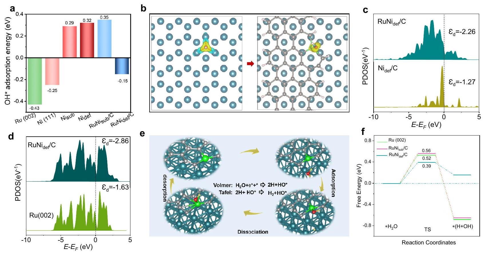
الشكل 1 | نتائج التنبؤ النظري بواسطة حساب DFT. أ طاقة الامتزاز للوسط OH على المواقع النشطة لتفاعل الهيدروجين (HER) المرتبطة بنماذج مختلفة. ب نتائج حساب كثافة الشحنة التفاضلية لـ OH لـ و نماذج، حيث يشير اللون الأصفر إلى تراكم الشحنة، ويشير اللون الأزرق الفاتح إلى استنفاد الشحنة.PDOS للنيكل والروثينيوم و . هي HER
الملخص
عملية التفاعل لـنموذج تحت ظروف قلوية.إحداثيات التفاعل لعملية HER لسطح Ru (002)، و نماذج. رموز الألوان للعناصر: الكربون (رمادي)، الأكسجين (أحمر)، الهيدروجين في الماء (أصفر-أخضر)، الهيدروجين على الحافة (أبيض)، النيكل (أخضر)، والروثينيوم (أزرق داكن).
العمل (الشكل التوضيحي التكميلي 3ب)،تشغل المواقع الكربونية المعيبة، في حين لا يوجد ارتباط بين الروثينيوم والنيكل. يتم عكس الهيكل الإلكتروني المعقد أولاً في كثافة الشحنة التفاضلية لـ OH، للتحقيق في قدرة إمداد الشحنة لنماذج هيكلية مختلفة لمجموعة OH. تُظهر الشكل 1 ب والشكل التكميلي 10 إعادة توزيع الشحنة المرتبطة بـ OH للروثينيوم النشط في نموذج مع إدخال ذرة النيكل المفردة المثبتة على الكربون المعيب، حيث يعمل الكربون المعيب كجسر كربوني (مكتبة إلكترونية) لإنشاء اتصالات شحن OH بين مواقع النيكل والروثينيوم، مما يؤدي إلى الامتصاص التآزري لوسائط OH بين الموقعين. لذلك، فإننموذج، مع تقليل تراكم الشحنة على الروثينيوم من خلال تعديليضمن امتصاصًا أضعف لـ OH مقارنةً بـ Ru النقي (002). بالإضافة إلى ذلك، تم استخدام الكثافة الجزئية للحالات (PDOS) لفحص التفاعلات الإلكترونية بين مواقع Ru و Ni وبالتالي لتحليل أسباب تغييرات طاقة امتصاص OH. كما هو موضح في الشكل 1c، فإن إدخالتسبب إدخال Ru في تحول هابط لمركز نطاق dإلىوبالتالي تسبب في ضعف امتصاص OH على موقع النيكل. بينما كماعندما يدخل النظام النقي للروثينيوم، يتحول مركز نطاق d من -1.63 eV إلى -2.86 eV (الشكل 1d) بسبب إعادة ترتيب الإلكترونات حول الروثينيوم، وتضعف عملية امتصاص الروثينيوم على OH. ومن الجدير بالذكر أن التفاعلات الإلكترونية بين الروثينيوم والنيكل تضعف امتصاص OH بواسطةوبذلك تقليل حاجز طاقة التحلل النهائي للماء.
بعد ذلك، قمنا بدراسة العلاقة القابلة للتنبؤ بين الخصائص المذكورة أعلاه وحاجز الطاقة لتفاعل الهيدروجين (HER) من خلال حسابات DFT. في تفاعل الهيدروجين القلوي لـالامتصاص الأولي لـحدثت الجزيئات بشكل انتقائي على موقع الروثينيوم، كما هو موضح في الشكل 1e والأشكال التكميلية 11-12. يتم تحديد هذا الموقع على الروثينيوم كموقع نشط حرج للإعلانات ومركز نشط من خلال تجربة التسمم، كما هو مفصل في الشكل التكميلية 16. بعد هذا الامتصاص الأولي،جزيئات تعرضت للتفكك من خلال خطوة فولمر، مما أدى إلى إنتاج و من الجدير بالذكر أن الوسيط OH المتكون في حالة الانتقال يتم امتصاصه بشكل خاص إلىالموقع (الشكل التوضيحي 12ب)، مما يوضح التأثير التآزري لتحلل الماء بينومواقع Ru. أخيرًا، تم إنشاءخضعت للتحويل إلىمن خلال خطوة تافل وتم إزالتها من السطح. وفقًا للنظرية الحاسوبية، فإن الروديوم لديه قدرات امتصاص قوية للوسائط. أو بسبب كفاءتها الفعالة في تحليل المياه، والتي تتماشى جيدًا مع نظريتنا السابقة توضح الشكل 1f أن Ru (002) يظهر حاجز طاقة حالة الانتقال قدره 0.52 إلكترون فولت قريب من ذلك لـ، مما يشير إلى أن له تأثير ضئيل على إضعاف امتصاص OH لتقليل حاجز طاقة تفكك الماء النهائي. ومع ذلك، فإن حاجز طاقة الحالة الانتقالية المنخفض يبلغ 0.39 إلكترون فولت لـيشير إلى أنهو الأمثل لتنظيم طاقة الامتزاز للوسائط وتسريع تفكك الماء على الروديوم النشط، مما يؤدي إلى ميزة ملحوظة في تفاعل الهيدروجين القلوي. ومن الجدير بالذكر أن حواجز طاقة الحالة الانتقالية إيجابية لجميع النماذج، وهو ما يتماشى مع النتائج التي تم الإبلاغ عنها مؤخرًا.. بالإضافة إلى ذلك، فإن نموذج سبيكة RuNi لديه حاجز طاقة حالة انتقال أعلى يبلغ 0.7 إلكترون فولت (الأشكال التكميلية 13-14)، مما لا يعكس ميزة على المعدن النقي و ، مما يثبت بشكل أكبر تأثير التعديل الفريد لذرات النيكل المفردة المثبتة على الكربون المعيب على نانو كريستالات الروثينيوم. ومع ذلك، من الجدير بالذكر أن كل من سبيكة الروثينيوم والنيكل وتحسين امتصاص الهيدروجين إلى حد ما (الشكل التكميلي 15). لتلخيص ذلك، من المتوقع أن يكون الروثينيوم وتسهل المواقع الحفازة امتصاصًا تآزريًا لـحيث أن الكربون المعيب كحلقة يعزز التفكك المائي التآزري بين مواقع الروثينيوم والنيكل وإزالة الوسائط، مما يؤدي إلى نشاط معقول في تفاعل الهيدروجين القلوي.
تركيب المواد وخصائصها
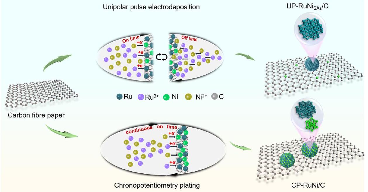
استنادًا إلى هذه النظريات، حاولنا تجميع ذرة نيكل واحدة لتعديل هيكل نانوي كريستالي روديول صغير للغاية. التحدي الرئيسي في تحقيق هذا الهدف هو إدارة التكتل السريع والتكوين أثناء تخليق المحلول، مما يعيق في النهاية تشكيل الذرات المفردة. تم استخدام استراتيجية UPED فريدة هنا للتحكم في تثبيتعلى العيب الكربوني، مما يضمن التشتت لـلتعديل جزيئات نانو روثينيوم فائقة الصغر. على وجه التحديد، تقليل و حدث عندما تم تشغيل التيار، معيتم تقليله بشكل تفضيلي. ثم سمح فصل التيار بانتشار أيون المعدن إلى الكاثود، مما حافظ على استعادة تركيزه (الأشكال التكميلية 17-18 والشكل 2). التعويض الذي تم الحصول عليه بواسطةأثناء المرحلة غير النشطة، يضعف الجهد الزائد لترسيب الروديوم، مما يضمن بشكل فعال الترسيب طويل الأمد للروديوم بدلاً من النيكل. في المرحلة النهائية، يبدأ النيكل في الترسيب وتتشكل. بالمقابل، فإن الطريقة التقليدية للجهد الثابت تولد جهدًا زائدًا بسبب الاستقطاب التركيزي نتيجة للاستهلاك المستمر لـ، مما يسبب لتقليلها في وقت سابق والتجمع في سبيكة CP-RuNi/C (الشكل التكميلي 19 والشكل 2).
الشكل 2 | توضيح لإجراء تخليق UP-RuNi و المحفزات CP-RuNi/C. (I) UP-RuNi المحفز الذي تم الحصول عليه من خلال التحكم في حالات التيار المتقطع (تشغيل وإيقاف) عبر استراتيجية UPED؛ (II) تم الحصول على محفز CP-RuNi/C من خلال التحكم في توصيل التيار المستمر عبر استراتيجية جهد ثابت.
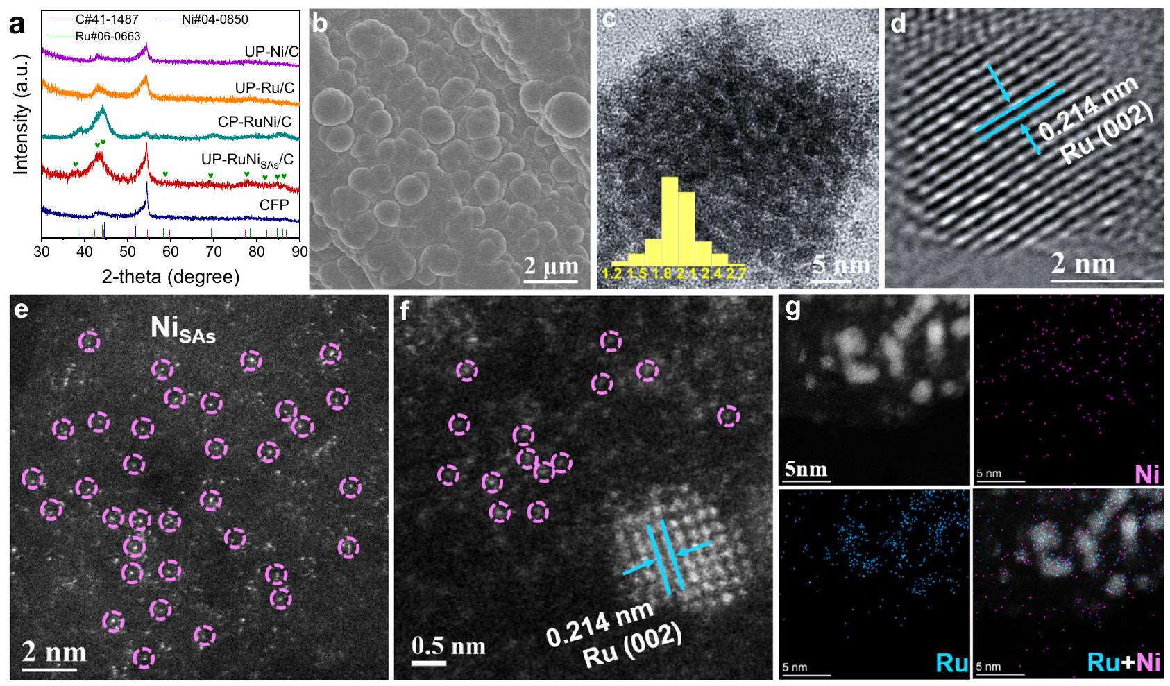
أنماط حيود الأشعة السينية (XRD) لـ UP-RuNi و CPRuNi/C (الشكل 3a والأشكال التكميلية 20-21) تظهر قمم الحيود التي تتوافق مع Ru (رقم PDF 06-0633)، مع الحجم الجزيئي الصغير لجزيئات Ru لـ UP-RuNi واضح من القمم الواسعة. بشكل خاص، نمط XRD البطيء المسح لـ UP-RuNiيظهر قمم الحيود لبلورات النانو من الروثينيوم (رقم PDF 06-0633) ولا يوجد إشارة حيود للنيكل، الذي كان يُعتقد في البداية أنه محتوى ضعيف من النيكل أو وجودكما هو موضح في الشكل 3b والشكل التكميلي 22a من صور المجهر الإلكتروني الماسح (SEM)، فإن الجسيمات الشبيهة بالتكتلات بحجم حواليفي الحجم كانت محملة بشكل موحد على الركيزة الكربونية، وأظهر التكبير الإضافي (الشكل التوضيحي 22b) أن هذه الجسيمات بحجم حواليفي الحجم تتجمع من جزيئات نانوية أصغر لتشكيل سطح خشن. صورة المجهر الإلكتروني الناقل (TEM) والرسم البياني لتوزيع الحجم المقابل (الشكل 3c) أظهرا بشكل أكبر أن حجم البلورات النانوية يبلغ حوالي 2 نانومتر. كما هو موضح في الشكل 3d، فإن UP-RuNiعرضت حواف الشبكة بمقدار 0.214 نانومتر، مما يتوافق مع المستوى البلوري (002) للروثينيوم السداسي.ويمكن تمييز وتحديد بلورات النانو من الروثينيوم بدقة باستخدام تقنية المسح المجهري الإلكتروني بتصحيح الانحراف الكروي (AC-STEM). كشفت الشكل 3e عن التشتت المتجانس للنقاط الساطعة، مما يشير إلى التوزيع المتجانس للذرات الفردية عالية التباين على ورق الألياف الكربونية (CFP). بالإضافة إلى ذلك، تتيح تقنية AC-TEM عالية الدقة ملاحظة النقاط الساطعة المتناثرة، بينما يمكن رؤية بلورات الروثينيوم الأكثر سطوعًا بسبب العدد الذري الأكبر، ويمكن كشف سطح Ru (002) (الشكل 3f). يمكننا أن نفترض بشكل أولي أن النقاط الساطعة المتناثرة حول بلورة الروثينيوم هي، والتي تم التحقق منها بشكل إضافي من خلال STEM-EDS. من الشكل 3g، يمكن ملاحظة أن عنصر الروثينيوم موزع بشكل موحد في موقع النانوكريستال، بينما عنصر النيكل موزع بشكل موحد حول الركيزة والروثينيوم. تم تحليل محتويات الروثينيوم والنيكل في المحفزات بدقة باستخدام مطيافية الانبعاث الضوئي بالتحليل الطيفي بالاقتران البلازمي (ICP-OES)، مما يكشف عن النسب الذرية لـلـفي UP-RuNi و في CP-RuNi/C على التوالي (الشكل التوضيحي 23). أظهر محفز CP-RuNi/C تشكل (الشكل التكميلي 26 أ، ب) يشبه ذلك الخاص بـ UPمتوسط حجم الجسيمات النانوية في CP-RuNi/C حوالي 5 نانومتر، وهو ما تم تأكيده من خلال الشكل التوضيحي الإضافي 26c. كشفت صورة HRTEM لـ CP-RuNi/C عن خطوط شبكية بحجم 0.214 نانومتر و0.203 نانومتر تتوافق مع المستويات (002) و(111) للروثينيوم السداسي والنيكل المكعب، على التوالي، مما يؤكد تكوين السبيكة للحفاز (الشكل التوضيحي الإضافي 26d). من الجدير بالذكر أن أنماط XRD ذات المسح البطيء لحفاز CP-RuNi/C (الشكل التوضيحي الإضافي 20) اكتشفت فقط قمة الانكسار لبلورة الروثينيوم. كانت قمة الانكسار المقابلة لبلورة النيكل ضعيفة جداً أو من الصعب اكتشافها بسبب المحتوى المنخفض من النيكل في الحفاز مقارنة بالروثينيوم، وهو ما تم إثباته بواسطة ICP-OES (الشكل التوضيحي الإضافي 23). علاوة على ذلك، يمكن أيضاً تحضير بلورات نانوية نقية من الروثينيوم (UP-Ru/C) بحجم يقارب 3 نانومتر (الشكل التوضيحي الإضافي 27) من خلال استراتيجية UPED، مما يدل على اتساقها في التحكم في حجم البلورات النانوية.
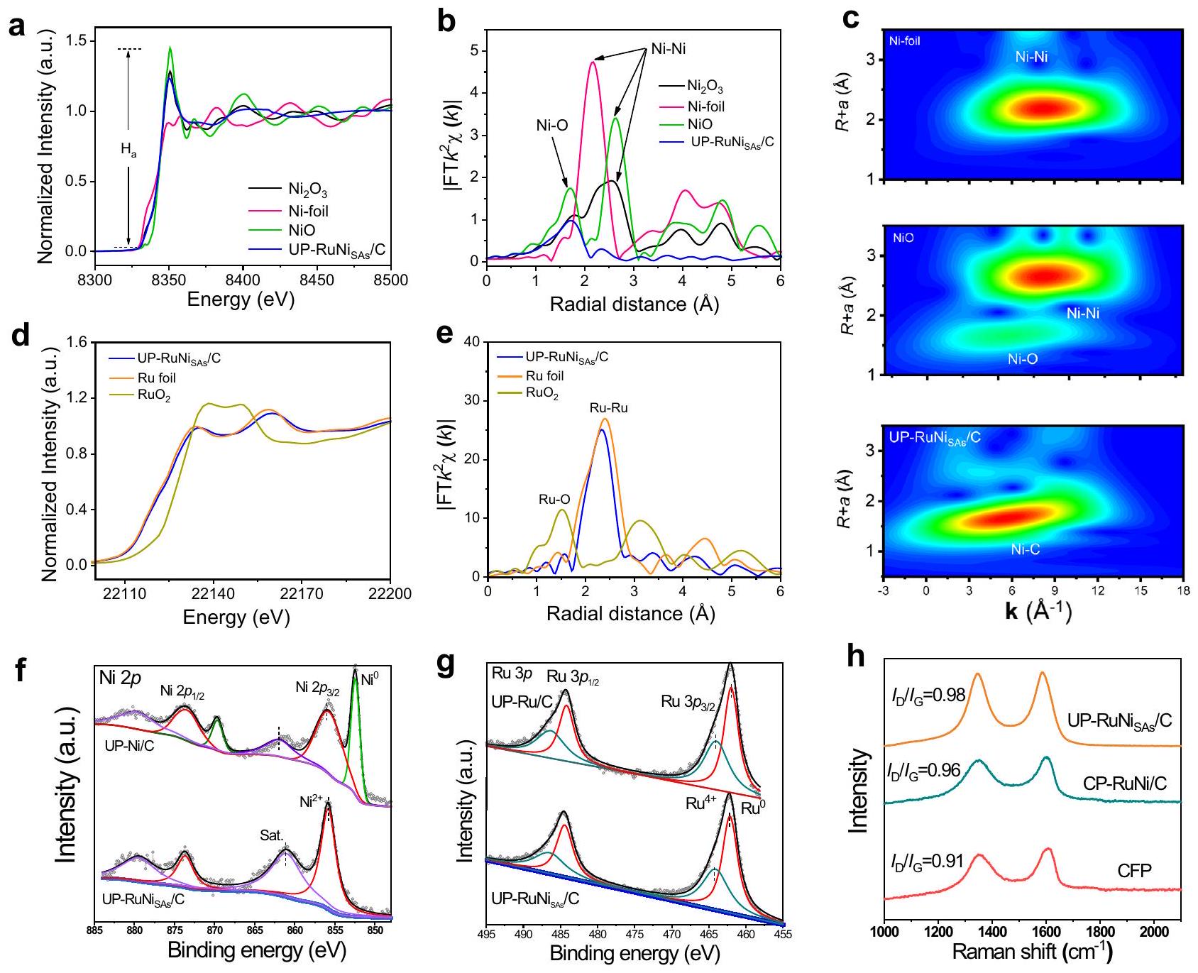
قمنا بإجراء مطيافية امتصاص الأشعة السينية (XAS) عند النيكل-حافة UP-RuNiلشرح تشتت الذرة الواحدة من النيكل. بالمقارنة معورقة النيكل،-طيف امتصاص الأشعة السينية بالقرب من الحافة (XANES) لـ UP-RuNisكان مختلفًا بشكل ملحوظ مع حافة رقائق النيكل وNiO، مع الخط الأبيض بينهما، مما يؤكد هيكله التنسيقي المميز (الشكل 4أ). بشكل عام،ستحدث الهجينة لـعناصر المعادن الانتقالية مثل النيكل عندما تفقد ذرات التنسيق تناظر مركزها، مما يؤدي إلى زيادة شدة الخط الأبيض.. الـمن حافة النيكل تظهر زيادة مقارنة برقائق النيكل، مما يدل على تزاوج النيكل مع ذرات غير متجانسة مثل الكربون في CFP. كما هو موضح في الشكل 4b لتحويل فورييه-طيف الامتصاص الدقيق للأشعة السينية الممتد (EXAFS) الموزون لـ UP-RuNiلم يتم العثور على قمم ربط معدني في مقارنة مع وورق النيكل، مما يؤكد أن النيكل موزع ذريًا وأنه لا يوجد تنسيق معدني-معدني لذرات النيكل الفردية في UP-RuNiج. من الجدير بالذكر أن هناك ذروة ارتباط عند، واعتقدنا أنه قد يت correspond إلى كمية صغيرة من المعدلة
الشكل 3 | التوصيف الفيزيائي والشكل الخارجي لـ UP-RuNisAs/C. أ أنماط XRD. ب صورة SEM. ج صورة TEM (الملحق: هيستوغرام توزيع الحجم). د صورة HR-TEM. هـ،تصحيح الانحراف الكروي في STEM، حيث تُنسب البقع الساطعة المميزة بالدوائر الوردية إلى ذرات النيكل الفردية.رسم خرائط STEM-EDS لـ UP-RuNi.
الشكل 4 | توصيفات حول الحالات الكيميائية والهياكل الدقيقة. أ نيتحليل XANES على حافة UP-RuNi، ورقة النيكل. ب تحويلات فورييه لطيف EXAFS عند -حافة UP-، ورقة النيكل. ج التحويلات الموجية لـ -وزن EXAFS علامات UP-RuNiني أو ، ورقة النيكل.تحليل XANES على حافة UP-RuNiرقائق، وتحويل فورييه EXAFS
طيف UP-RuNiورق رو في رو-حافة.تحليل طيف XPS عالي الدقة لـلـ UP-Ni/C، UP-Ru/C، و UP-RuNiالمحفزات. تحليل طيف XPS عالي الدقة للروثينيوملـ UP-Ni/C، UP-Ru/C، و UP-RuNiالمحفزات. تحليل رامان لـ CFP و CP-RuNi/C و UP-RuNiمحفزات. الأكسدة أو التهجين مع الكربون. تحويلات الموجة الصغيرة (WT) لـ EXAFS عندتم استخدام -edge لمزيد من التحقيق في خصائص التنسيق لـ UP-RuNi. ل UP-RuNi، لاتم ملاحظة إشارة WT في الشكل 4c على عكس رقائق النيكل وNiO في. على النقيض، تم ملاحظة تنسيق النيكل مع عنصر غير معدني في بالنظر إلى أن ركيزة المحفز هي الكربون، نفترض أنه قد يكون تنسيق Ni-C. لقد تحققنا من الافتراض أعلاه باستخدام معلمات تركيب EXAFS عند النيكل.-edge مدرج في الشكل التوضيحي 29 والجدول التوضيحي 5. كما هو متوقع، هيكل التنسيق لـتم الحصول عليه عن طريق التوفيق بينالمسار هو الأمثل وعدد التنسيق (CN) أكبر من ذلك لـ (الذي يحدث بسبب الأكسدة السطحية). من الجدير بالذكر أنه، كما يتضح من غياب رابطة Ni-Ru في الشكل 4b ومن تحليل EXAFS في الجدول التكميلي 5، لا توجد رابطة بين Ni و Ru. تؤكد النتائج المذكورة أعلاه أن Ni مثبت على الكربون في UP..
لمزيد من استكشاف تنسيق الروثينيوم، تم استخدام التحليل بالأشعة السينية الممتصة (XAS) عند الروثينيوم.تم تسجيل -edge. الشكل 4d و e يعرضان XANES و EXAFS لـ UPمع رقائق الروثينيوم وكنماذج مقارنة. الـطيف XANES لحافة UP-RuNiأظهر موضعًا واتجاهًا مشابهين لرقائق الروثينيوم، ولكن مع تحول إيجابي طفيف في الحافة القريبة. وميزات الخط الأبيض (الشكل 4d). وهذا يشير إلى أن Ru في UPكان مؤكسدًا قليلاً في الهواء. وجود تنسيق Ru-Ru لـيتضح من المقارنة مع رقائق الروثينيوم، كما هو الحال مع UPأظهر مسار Ru-Ru مميز عند حوالي بواسطة نتائج EXAFS في الشكل 4e. إشارة Ru-Ru WT لـ UP-RuNi (الشكل التوضيحي 30) أظهر أيضًا تنسيق Ru-Ru في نانو كريستالات Ru مقارنةً بورق Ru، مع تنسيق Ru-Ru متسق مع عينات ورق Ru الملاحظة عند هيكل التنسيق Ru-Ru لعنصر الروثينيوم فييتضح ذلك أكثر من خلال معلمات تركيب EXAFS عند حافة Ru K في الشكل التكميلي 31 والجدول التكميلي 6، وأظهرت معلمات التركيب انخفاضًا في متوسط CN لـفيمقارنةً بورق الروثينيوم، ربما بسبب الحجم الأصغر لجزيئات الروثينيوم النانوية في UP-RuNiالعوامل المساعدة (تأثير النانو)، وزيادة عدد ذرات السطح تؤدي في النهاية إلى عدد غير كافٍ من ذرات التنسيق. يتم الاستنتاج أولياً أن ذرات النيكل المفردة تعدل جزيئات الروديوم النانوية عبر جسر الكربون (UP-RuNiتمت عملية التخليق بنجاح، حيث تم تثبيت ذرات النيكل الفردية على الكربون الأساسي.
تم فحص خصائص سطح المحفزات بواسطة مطيافية الأشعة السينية للأشعة السطحية (XPS). كما هو موضح في الشكل التكميلية 32a، أكد طيف XPS الاستقصائي وجود، و C على سطح UP-RuNiالمحفز. الملائمطيف UP-RuNi (الشكل 4f) يظهر القيم الخاصة بـ عند 856.1 إلكترون فولت و 873.9 إلكترون فولت بسبب الأكسدة السطحية. على ما يبدو، لم يتم عرض الذروة في UP-RuNi، وهو ما يتماشى مع نتائج AC-STEM، حيث يتواجد النيكل في شكل ذرات مفردة. على النقيض من UP-RuNiالمناسبطيف في UP-Ni/C عرضتبلغ القمم 852.51 إلكترون فولت و 869.71 إلكترون فولت. ومع ذلك، تم نقل القمة إلى طاقة ربط أقل مقارنة بتلك الخاصة بـ UP-Ni/C. الروديوم ( 462.15 إلكترون فولت و 484.13 إلكترون فولت ) و و 486.48 إلكترون فولتقمم UP-RuNi (الشكل 4g) انتقل بشكل إيجابي إلى طاقة ربط أعلى مقارنةً بتلك الخاصة بـ UP-Ru/C، مما يوحي بأن الإلكترونات انتقلت من Ru إلى Ni لـ UP-RuNi.. سيقمم ملائمة لـ UP-RuNi (الشكل التوضيحي 32ب) تم اكتشافه عند و ، وهو ما يتماشى مع نتائج XAS. الروتم تحليل القمم وتناسبها معوانتقال Ru-O. تم ملاحظة انتقال موضع قمة Ru-O إلى ارتباط أعلى مقارنة بـ UP-Ru/C، مما يشير إلى انتقال الإلكترون من Ru إلى C في UP-وبناءً عليه، فإن مسارات نقل الإلكترون داخل UP-RuNiهي Ru إلى Ni و Ru إلى C، مما يؤدي إلى بناء هياكل إلكترونية معدلة لكل عنصر لتحسين الأنشطة. بالإضافة إلى ذلك، فإن المعطيات الملائمةطيف الـ (الشكل التوضيحي 33a) يُظهر حالات التكافؤ لـ (عند 852.7 إلكترون فولت و 869.9 إلكترون فولت)، وهو أعلى من ذلك المبلغ عنه لـلكن مشابه لذلك الموجود في كربيدات النيكل، مما يوحي بإمكانية تشكيل، الذي تم دعمه من قبل قمم ملائمة (الشكل التكميلي 33c) عند 283.98 إلكترون فولت لطاقة الربط لـ.
علاوة على ذلك، تم تحميض-أكسدة سطح CFP (انظر المعلومات التكميلية للتفاصيل) لإدخال بعض المجموعات النشطة المحتوية على الأكسجين (مثل الهيدروكسيل)، مما يساعد في تثبيت المعدن.قمنا بتسجيل طيف رامان للكشف عن مدى عيوب الكربون وإدخال المواقع النشطة لـ CFP. كما هو موضح في الشكل التكميلية 34، كانت قيمة المعالجة الكهروكيميائية لـ CFP أعلى بكثير من تلك الخاصة بـ CFP النظيف، مما يدل على أن درجة عيوب الكربون بعد المعالجة المسبقة قد زادت بشكل ملحوظ. ومن المدهش أن نطاق عيوب الكربون لـ UP-RuNi كان أكثر امتلاءً بشكل ملحوظ من CP-RuNi/C المعتمد في الشكل 4h. قد تؤدي الجهود العابرة تحت ظروف النبض إلى إنتاج عيوب كربونية بشكل أكبر، والعيب الفخم هو موقع ربط مثالي لتثبيت أيونات المعادن لتحقيق تشتت ذري.لاحظ أنه خلال عملية UPED، من المرجح أن يتجمع الروديوم في شكل نانوكريستالات مقارنة بالنيكل بسبب طاقته التماسك الأعلى، مما يتيح مساحة لـمربوط بالكربون.
الأداء الكهروكيميائي
أنشطة HER في UP-RuNiتمت دراسة المحفز الكهربائي عند كثافات تيار عالية في محلول إلكتروليتي 1.0 م KOH. تم معايرة قطب الزئبق المشبع (SCE)، المستخدم كقطب مرجعي، فيالالكتروليت المشبع (انظر الشكل التوضيحي التكميلي 35)، وجميع الجهود هنا مُبلغ عنها بالنسبة إلى القطب الهيدروجيني القابل للعكس (RHE). أولاً، تم تلخيص قياسات الفولتامترية المسحية الخطية (LSV) للمواد الحفازة التي تم الحصول عليها بواسطة UPED تحت ظروف مختلفة في الشكل التوضيحي التكميلي 36. UP-Ru/C، UP-Ni/C، CP-RuNi/C، وتمت مقارنة المواد في نفس الوقت. كما هو موضح في الشكل 5a، UP-RuNiأظهرت أعلى نشاط لتفاعل تطور الهيدروجين، مع جهد زائد قدره 9 مللي فولت فقط و253 مللي فولت لتوليد كثافة التيار من و على التوالي، أصغر بكثير من ذلك بالنسبة للتجاريفي. بالإضافة إلى ذلك،أنتجت جزيئات نانوية صغيرة جدًا من الروثينيوم بدلاً من سبائك الروثينيوم والنيكل ثنائية المعدن خصائص متفوقة، كما يتضح من الجهد الزائد البالغ 33 مللي فولت عندلـ CP-RuNi/C بنفس التحميل. تم تقديم منحنيات LSV بدون تعويض iR في الشكل التكميلية 37، والتي تتماشى مع الشكل 5a الذي يظهر الأداء الأمثل لتفاعل الهيدروجين (HER) لـ UP-RuNi.لإظهار تميز ركيزة الكربون، قمنا بإيداع نفس UP-RuNiالمحفز على دعم شعر التيتانيوم باستخدام استراتيجية UPED. أظهرت النتائج أن أداء
UP-RuNiكان لا يزال أدنى من ذلك في UP-RuNi (الأشكال التكميلية 38-40)، مما يوضح تمامًا المزايا الفريدة لمواقع الكربون في UP-RuNiميل تافل لـ UP-RuNiتم تعيينه كأدنى قيمة لـ (الشكل 5ب) بين UP-Ru/C و UP-Ni/C و CP-RuNi/C و Pt/C التجاري، مما يشير إلى أسرع حركية لتفاعل الهيدروجين. من المهم أن الميل المنخفض لجدول تافل للمواد القائمة على الروثينيوم يشير إلى أن الخطوة المحددة لمعدل التفاعل هي إزالة الوسط OH، بدلاً من تحلل الماء.تردد الدوران (TOF) هو وصف حاسم لتوضيح النشاط الجوهري للمحفزات. لذلك، تم تحديد قيم TOF وعدد المواقع النشطة للمحفزات الكهربية بواسطة طريقة ترسيب النحاس تحت الجهد (UPD) (الشكل التوضيحي التكميلي 42a-e). كما هو موضح في الشكل التوضيحي التكميلي 42f، فإن قيم TOF لـ UP-RuNiعند الجهد الزائد 20 مللي فولت و 50 مللي فولت كانت و ، أعلى بكثير من تلك الخاصة بالعوامل المساعدة الأخرى المبلغ عنها حتى الآن في هذا العمل. قيم TOF لـ UP-RuNiيقارن بشكل إيجابي مع معظم المحفزات في الشكل 5c والجدول التكميلي 7، مما يثبت مرة أخرى النشاط الجوهري الجيد لـ UP-RuNi.. استنادًا إلى تحميل كتلة المعدن الثمين Ru عند الجهد الزائد 20 مللي فولت و50 مللي فولت، قمنا بتحليل نشاط HER المنظم بشكل أكبر. UP-RuNiأظهرت أعلى نشاط كتلي، بقيمة 12.09 أمبير لكلوالذي هو 3.3 و 31.8 مرة أعلى من CP-RuNi/C و UP-Ru/C على التوالي، كما هو موضح في الشكل 5d.
تم استخدام مطيافية impedancia الكهروكيميائية (EIS) المستمدة من مخطط الدائرة المعادلة المقابل لاستكشاف قدرة نقل الشحنة (الشكل التكميلي 43)، حيث أظهرت UPRuNiSAs/C أقل مقاومات داخلية لنقل الشحنة.من و . (الجدول التكميلي 8)، مما يشير إلى الموصلية المثلى لـ UP-RuNi نحو HER. يمكن استخدام المساحة السطحية النشطة كهربائياً (ECSA) كمؤشر لتقييم عدد المواقع النشطة للمحفزات. كما هو متوقع، تم حساب سعة الطبقة المزدوجة ( ) القيمة ( الشكل التوضيحي 44 ) من UP-RuNiوفقًا لرسوم الفولتامترية الدورية (CV) عند معدلات مسح مختلفة (الشكل التكميلي 45) ثبت أنها الأعلىمما يؤدي إلى ارتفاع قيمة ECSA مقارنة مع CP-RuNi/C ( ) و Pt/C ( )، توضح قدرة UP-RuNi لتوفير مواقع نشطة أكثر لتعزيز أداء HER. من منظور الاستقرار على المدى الطويل واختبار CV متعدد الدورات، فإن التفوق الاستثنائي لـ UP-RuNiتم تأكيد ذلك بشكل أكبر للتطبيق العملي عند كثافات تيار عالية. كما هو موضح في الشكل التكميلية 46، فإن منحنيات الفولتية الحالية لـ UP-RuNiقبل وبعد آلاف الدورات، تظهر قياسات الجهد الحالي عدم وجود تغييرات كبيرة، حتى عند تعرضها لكثافة تيار مرتفعة نسبياً. هذا يؤكد القابلية العملية لـ UP-RuNi.ج، خاصة عند كثافات التيار العالية. الاستقرار على المدى الطويل لعملية التحليل الكهربائي للمياه الصناعية محدود إلى حد كبير بسبب تجاوز كثافة التيار. UP-RuNiتم إخضاعه لاختبار الكرونو بوتنشيومتر عند كثافة تيار قدرهاواحتفظت بالاستقرار المطلق لمدة 200 ساعة، متفوقة على المحفز الكهربائي التجاري Pt/C مع الانخفاض المستمر في الاستقرار (الشكل التكميلي 47). ومن الجدير بالذكر أن UP-RuNiكما أعطى استقرارًا لمدة 100 ساعة تحت كثافات تيار عالية تتراوح منإلى (الشكل 5e والشكل التكميلي 48)، مما يوضح الإمكانية للاستجابة الفعالة والمستمرة في إنتاج الهيدروجين الصناعي. بالإضافة إلى ذلك، فإن كمية تم تحديد ما تم إنتاجه خلال الساعات الثلاث الأولى عبر كروماتوغرافيا الغاز (الشكل التكميلي 49)، مما يوضح أن كفاءته الفارادائية كانت تقريبًا. أثبتت صور المجهر الإلكتروني الماسح (الشكل التكميلي 50) وقياس الطيف الكهروكيميائي (الشكل التكميلي 51) بعد الاختبار الكهروكيميائي استقرارها الكبير، حيث لم تتغير مورفولوجيا وحالة العناصر الرئيسية بشكل ملحوظ. علاوة على ذلك، فإن UP-RuNiكما قدمت أداءً إيجابيًا في تفاعلات الهيدروجين في الظروف الحمضية والمحايدة. كما هو موضح في الشكل التكميلية 52، فإن UP-RuNisتصرف بأفضل نشاط في 0.5 مومحلول عازل فوسفات 1.0 م، مع أقل جهد زائد يبلغ 18 مللي فولت و27 مللي فولت، على التوالي، وملحوظ
الشكل 5 | الأداءات الكهروكيميائية. أ،منحنيات الاستقطاب ومخططات تافل لـ UP-Ni/C، UP-Ru/C، CP-RuNi/C، UP-RuNi ومحفزات Pt/C التجارية في قيم TOF لـ UP-RuNiمقارنة مع والعوامل المحفزة التي تم الإبلاغ عنها سابقًا في نشاط تطبيع كتلة الروثينيوم UP-Ru/C، CP-RuNi/C، UP-RuNiالعوامل المساعدة في و في 1 م KOH. اختبار الاستقرار على المدى الطويل لـ UP-RuNisالعوامل المساعدة فيالمقارنة من حيث
الجهود الزائدة لـ UP-RuNiوتم الإبلاغ مؤخرًا عن المحفزات الكهربية عند كثافات تيار مختلفة ( و ) في 1.0 م كوه ومقارنة أداء pH-الكوني لـ UP-RuNi وقد أبلغت مؤخرًا عن المحفزات الكهروكيميائية الخاصة بها. كانت كمية التحفيزكان الرقم الهيدروجيني للإلكتروليت 13.6، وكانت مقاومة السائل حوالي. الدراجات الهوائية والاستقرار على المدى الطويل لمدة 28 ساعة مقارنة بـ Pt/C (الشكل التكميلي 53b والشكل التكميلي 55b). أخيرًا، يتم تلخيص نشاط HER العالمي وذو كثافة التيار العالية في pH والذي يتفوق على غيره من المحفزات الكهربائية المبلغ عنها في الشكل 5f والجدول التكميلي 11. جميع النتائج المذكورة أعلاه تُظهر النشاط الملحوظ لـ UP-RuNi.في كثافات تيار كبيرة جدًا لتفاعل الهيدروجين الكهربائي والأفق الكبير للتطبيقات.
لتحقيق في آفاق تطبيق UP-RuNiكمادة كاثود تحت ظروف صناعية فعلية، قمنا بإنشاء خلية إلكتروليتية تعتمد على غشاء تبادل الأنيونات. استخدمنا المنتج التجاريالمحفز كأنود وقارنت أداء UP-RuNiمع و المحفزات بشكل منفصل عند الكاثود تجارياًتم بناء خلية التحليل الكهربائي AEM في تكوين ساندويتش بمساحةيتكون من جامع تيار، محفز كاثود (أنود)، وغشاء أنيوني بدون ضغط حراري، كما هو موضح في الشكل 6a. كما توقعنا، فإن أداء إلكتروليزر AEM القائم على UP-RuNiتم تحسين المحفز ككاثود مع ارتفاع درجة الحرارة (الشكل 6ب). ومن المدهش أنه تم تسجيل جهد خلية منخفض قدره 1.70 فولت و 1.95 فولت عند و على التوالي فيلـ UP-RuNisالعامل المساعد، في حين أنوتم الحصول على جهد الخلية 1.91 فولت و 2.27 فولت على التوالي باستخدام Pt/C والعوامل الحفازة في (الشكل 6c والشكل التكميلية 57). والأهم من ذلك، كفاءات تحويل الطاقة لـ
خلية إلكتروليتية تعتمد على UP-RuNi و المحفزات هي و (الشكل 6د) عند . للتحقق من إمكانيات تطبيقها العملي على نطاق شبه صناعي، تم دراسة الاستقرار طويل الأمد للخلية الكهربائية لمدة تقارب 250 ساعة عند . كما هو موضح في الشكل 6هـ والشكل التكميلي 58، فإن UP-RuNis أظهرت استقرارًا طويل الأمد كبيرًا مع تقلبات جهد ضئيلة مقارنةً بمحفزات Pt/C و Ru/C، مما يشير إلى الآفاق الواعدة لـ UP-RuNi لإنتاج الهيدروجين.
الحركيات وآلية التفاعل لـ UP-RuNis لعملية HER القلوية
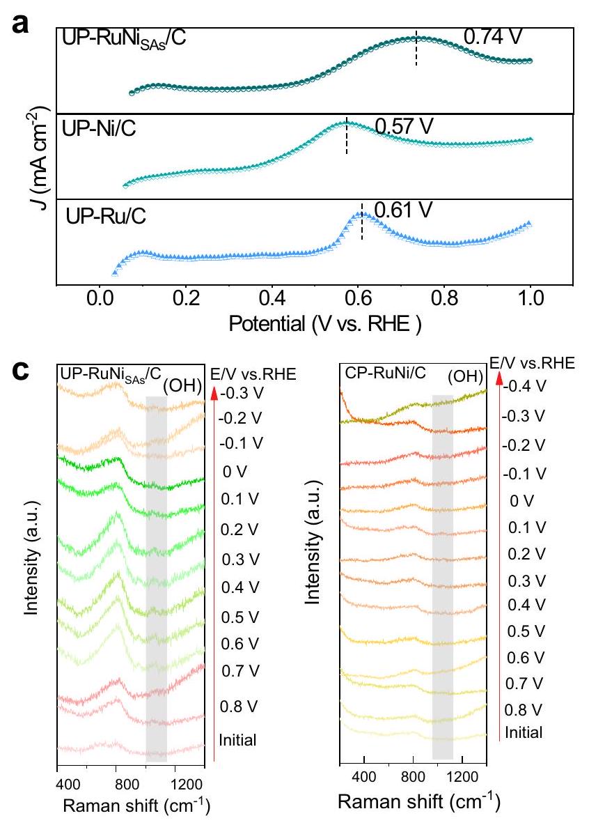
كما ذُكر أعلاه، فإن ميل Tafel المنخفض يؤكد أن الخطوة المحددة للسرعة في التفاعل هي إزالة OH الوسيطة. للحصول على فهم أعمق لآلية التفاعل لـ UP-RuNi تجاه HER القلوية ولرصد سلوك الامتصاص (الإزالة) المحدد لـ OH الوسيطة، أجرينا تجربة إزالة CO وقياس رامان أثناء التشغيل. يتم تحفيز الأكسدة الكهروكيميائية لـ CO بواسطة امتصاص OH النشط، وبالتالي يُعتبر الانزياح السلبي لجهد الأكسدة مؤشرًا على وجود ألفة أقوى لـ OH للمحفز . كما هو موضح في الشكل 7أ، أظهرت UP-RuNis أقل سعة امتصاص لـ OH مع جهد ذروة يبلغ 0.74 فولت مقارنةً بـ UP-Ru/C النقي (0.61 فولت)، مما يعني أن OH
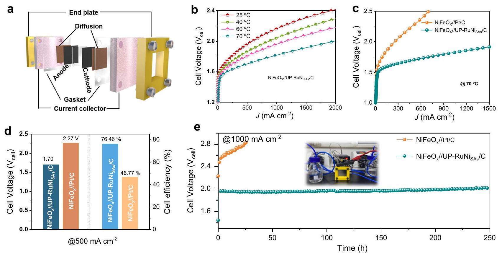
الشكل 6 | أداء HER القلوي في مفاعل AEM. أ رسم توضيحي تخطيطي لمفاعل AEM. تم تشغيل LSVs عند درجات حرارة خلوية مختلفة في خلية كهربائية AEM. ج منحنيات LSV لمفاعلات AEM باستخدام NiFeO و UP-RuNi كمصادر أنودية وكاثودية، على التوالي عند . د جهد الخلية
وكفاءة الطاقة للخلية الكهربائية AEM عند . هـ اختبارات الاستقرار لخلية الماء الكهربائية AEM عند . سعة تحميل المحفز هي ، كان الرقم الهيدروجيني للمحلول الكهربائي 13.6، وكانت المقاومة السائلة حوالي .
حركيات الإزالة لموقع Ru في UP-RuNis مع إدخال خلال خطوة فولمر. الجهد السلبي الأكثر لـ CP و مقارنةً بـ يشير إلى أن سعة امتصاص OH الأعلى لـ CP-RuNi/C في الشكل 7ب، مما يتسبب في انخفاض إعادة امتصاص الماء لموقع Ru في CP-RuNi/C.
تم إجراء قياس رامان أثناء التشغيل لاستكشاف التغيرات في الأنواع السطحية خلال HER القلوية. كما هو موضح في الشكل 7ج والشكل التكميلي 59، ظهرت أنواع OH (عند ) واختفت في وقت مبكر عند 0.6 فولت مقابل RHE و -0.1 فولت مقابل RHE لمحفزات UP-RuNi مقارنةً بـ UP-Ni/C (0.1 فولت مقابل RHE و -0.6 فولت مقابل RHE) و UP-Ru/C (0.4 فولت مقابل RHE و -0.3 فولت مقابل RHE) عندما تم تطبيق الجهود المنخفضة تدريجيًا، مما يعني أن ساعدت جزيئات Ru النانوية في إنتاج أنواع OH عبر تحلل الماء وإزالة OH عند جهد إيجابي نسبيًا . بالنسبة لـ في الشكل 7ج، فإن الجهد السلبي النسبي لحدوث OH (0.4 فولت مقابل RHE) واختفاء OH (-0.2 فولت مقابل RHE) أثبتت بشكل أكبر عملية حركية أدنى لتفكيك الماء وإزالة OH مقارنةً بـ -المزينة بجزيئات Ru النانوية، وأكدت المساهمة المميزة لـ لتعزيز تأثير الإزالة للوسائط OH على أسطح جزيئات Ru النانوية. علاوة على ذلك، فإن الإزالة السريعة للفقاعات عند كثافات تيار عالية تؤثر مباشرة على الاستقرار الميكانيكي للقطب، والتفاعل بين المحفز والمحلول الكهربائي، وفي النهاية تؤثر على النقل الكلي للكتلة. تلعب الإزالة السريعة للفقاعات دورًا رئيسيًا في هذه العمليات . لذلك، قمنا بدراسة المحبة للماء لمواد مختلفة من خلال اختبار زاوية الاتصال. كما هو موضح في الشكل التكميلي 60، فإن المحفز الكهربائي UP-RuNi أعطى أصغر زاوية اتصال تبلغ ، أقل بكثير من تلك الخاصة بـ UP-Ru/C () و CP-RuNi/C ()، مما يثبت المحبة المناسبة للماء لـ UP لتكوين فقاعات صغيرة بشكل ملائم وإطلاق الفقاعات لنقل الكتلة.
بشكل عام، يوضح الشكل 7د العملية التفصيلية للنظام التحفيزي بالكامل لتعزيز تحلل الماء وإنتاج الهيدروجين. من ناحية، تعزز التفكك السريع للماء لـ Ru لإنتاج وسائط OH؛ من ناحية أخرى، بسبب الامتصاص الضعيف لـ على وسائط OH، يتم ربط بشكل متزامن بـ Ru مع حركيات محسّنة في إزالة
وسائط OH، مما يمنع الامتصاص القوي لوسائط OH بواسطة Ru. بينما يتم تحقيق هذه العملية من خلال مصفوفة الكربون كجسر كربوني، مما يسمح بالاستجابة الدورية الديناميكية الحرارية والحركية بين الموقعين.
نقاش
أبلغنا عن تعديل ذرة النيكل المفردة لهيكل جزيئات Ru النانوية الصغيرة جدًا (UP-RuNi ) لإنتاج الهيدروجين بكثافة تيار عالية مستمرة ودرجة حموضة عالمية. يمكن أن تعمل المحفز بشكل مستقر لمدة 250 ساعة في خلية كهربائية AEM عملية. متصلة على عيوب الكربون، تلعب دورًا حاسمًا في عملية HER، مما يؤدي إلى تحسين حركيات الامتصاص للوسائط عند الموقع النشط لجزيئات Ru النانوية. وهذا يؤدي إلى التنظيم الفعال لطاقة الامتصاص وبيئة الإلكترونات. بشكل خاص، يتم ضمان إعادة امتصاص مستمرة لجزيئات الماء عند الموقع النشط من خلال الامتصاص المتزامن لوسائط OH مع . وبالتالي، يضمن ذلك توليد الهيدروجين المستمر والفعال عند كثافات تيار عالية. ستوفر جهودنا هنا نهجًا جديدًا للتصميم المنسق لمواقع الذرات المفردة لأنظمة التحفيز الفعالة في خلايا AEM الكهربائية العملية، كما ستسلط الضوء على أهمية النظر في المحفزات الكهربائية البديلة لـ Pt لمفاعلات أخرى ذات مستوى صناعي.
طرق
المواد
كلوريد سداسي هيدرات ()، حمض البوريك ()، كلوريد الأمونيوم ()، فوسفات البوتاسيوم ثنائي القاعدة اللامائي ()، فوسفات البوتاسيوم ثنائي الهيدروجين ، هيدروكسيد البوتاسيوم وبولي فينيل بيروليدون (PVP)، الأمونيا تم شراؤها من Aladdin، وحمض الكبريتيك المركز ()، كبريتات النحاس خماسية الماء ()، حمض النيتريك المركز ()، حمض الإيثيلين ديامين تترا أسيتيك، حمض ثيوسيانات البوتاسيوم (KSCN) والماء النقي () تم شراؤها من شركة الأدوية الوطنية الصينية المحدودة. تم الحصول على كلوريد الروثينيوم المائي () من شركة بكين إنوكيم تكنولوجي المحدودة. تم استخدام جميع المواد الكيميائية كما هي دون أي تنقية أخرى.
الشكل 7 | تجربة إزالة CO وخصائص طيفية أثناء التشغيل. أ، ب تجربة إزالة CO للمحفز UP-Ni/C، UP-Ru/C، و UP-RuNi التي تم الحصول عليها بواسطة UPED و CP-Ni/C، CP-Ru/C، و CP-RuNi/C التي تم الحصول عليها بواسطة CP.
د
ج تجارب قياس رامان أثناء التشغيل لـ UP-RuNi و CP-RuNi/C. د آلية التفاعل لمحفز UP-RuNi .
التركيبات
تركيب UP-RuNi . تم استخدام جهاز ثلاثي الأقطاب متصل بجهاز عمل كهربائي ECLab لإيداع المحفزات الكهربائية، مع جهد مرجعي مشبع كجهد مرجعي، وسلك بلاتيني كقطب مضاد، وقطب CFP () كقطب عمل. قبل الإيداع الكهربائي، خضعت ورقة الكربون النظيفة لعملية تنشيط مسبقة: تم نقع ورقة الكربون النظيفة أولاً في لمدة 30 دقيقة، ثم تم تنشيطها بواسطة CV في محلول الإلكتروليت لمدة خمس دورات، حيث كانت نطاق المسح هو مقابل RHE. لتحضير المحفز الكهربائي UP-RuNi ، تم إعداد 100 مل من محلول الطلاء، والذي يحتوي على . تم ضبط الرقم الهيدروجيني على 2.7 باستخدام ، وتم الحصول على UP-RuNi بواسطة طريقة UPED مع جهد نبضي قدره لمدة 4000 نبضة (8000 ثانية). تم تحديد كتلة تحميل المحفز لتكون .
تركيب UP-Ru/C و UP-Ni/C. تم تركيب المحفزات الكهربائية UP-Ru/C و UP-Ni/C بنفس الطريقة المستخدمة في UP، باستثناء عدم إضافة و إلى محلول الطلاء على التوالي. تم تحديد كتلة تحميل المحفز لتكون .
تركيب UP-RuNi . تم تركيب UP-RuNi بنفس الطريقة المستخدمة في UP-RuNi ، باستثناء أن الفلّين التيتانيوم الطازج كانت كقطب عمل.
تركيب CP-Ni/C و CP-Ru/C و CP-RuNi/C. في تحضير نموذجي لـ CP-RuNi/C، تم إعداد محلول الطلاء بنفس التركيبة المستخدمة في تركيب UP-RuNi ، وتم الحصول على المحفز الكهربائي بواسطة طريقة الطلاء بالجهد الثابت (CP) مع جهد ثابت قدره -0.8 فولت (مقابل ) لمدة 8000 ثانية، وتم استخدام نفس الطريقة لتحضير و CP ، باستثناء عدم إضافة و إلى محلول الطلاء على التوالي. تم تحديد كتلة تحميل المحفز لتكون .
تخليق محفز Pt/C. لتحضير محفز Pt/C الكهربائي، تم تحميل 20% من مسحوق Pt/C التجاري على CFP بطريقة التنقيط بكتلة تحميل قدرها .
تحليل
تم تحليل شكل المحفزات باستخدام المجهر الإلكتروني الماسح (SEM، 3 كيلوفولت، Hitachi-SU8010)، والمجهر الإلكتروني الناقل (TEM، 200 كيلوفولت، JEOL JEM 2100F) والمجهر الإلكتروني عالي الدقة المصحح للانحراف HAADF-STEM (FEI Titan G2 60-300). تم جمع بيانات التحليل الطيفي بالأشعة السينية المشتتة للطاقة على نظام IXRF SDD 2610. تم إجراء تحليل الأشعة السينية باستخدام جهاز تحليل الأشعة السينية Bruker D8 Advance مع إشعاع Cu Ka. تم تشغيل ICP-OES باستخدام جهاز Agilent 5110. تم استخدام التحليل الطيفي للأشعة السينية (XPS، Thermo VG ESCALAB250) لتحليل طاقة الربط السطحية. تم إجراء قياسات هيكل امتصاص الأشعة السينية (XAS) في خط الشعاع 4B9A من منشأة الإشعاع المتزامن في بكين تحت ظروف الحلقة 2.2 GeV وحوالي . دقة الطاقة العامة
لحافة Ni K تبلغ حوالي 1.5 eV بسبب دقة طاقة المطياف التي تبلغ حوالي 1.4 eV. تم إجراء معالجة بيانات EXAFS باستخدام برنامج Athena وArtemis من حزمة IFEFFIT
.
تم جمع بيانات رامان باستخدام جهاز Renishaw inVia.
القياسات الكهروكيميائيةتم استخدام محطة العمل الكهروكيميائية VMP3 لإجراء أداء HER للمحفزات الكهربائية في نظام ثلاثي الأقطاب، حيث تم استخدام قضيب الجرافيت كقطب مضاد، وتم ترسيب المحفز الكهربائي في الموقع على CFP كقطب عمل، وتم استخدام SCE كقطب مرجعي وتم معايرة المرجع إلى RHE باستخدام صيغة الحساب: . تم استخدام اختبارات الأقطاب محلول إلكتروليتي من ، 1.0 M PBS على التوالي عند . تم إجراء اختبار LSV بمعدل مسح قدره بعد 1000 دورة من اختبار CV عند للتفعيل والتحقيق في استقرار الدورة. تم استخدام قياس الجهد الزمني للتحقيق بشكل أكبر في الاستقرار طويل الأمد للمحفزات الكهربائية عند . تم تنظيم جميع منحنيات LSV بواسطة -iR تعويض. تم تقدير ECSA بواسطة طريقة CV، التي أجريت عند معدلات مسح مختلفة مع نطاق جهد قدره 0.1 V، والصيغة المحسوبة هي
. تم إجراء طيف impedancia الكهروكيميائية (EIS) عند حوالي -10 mV على مدى نطاق التردد من 1.0 إلى .تم حساب قيمة TOF بواسطة الصيغة: . حيث يمثل I كثافة التيار المقابلة عند جهد زائد معين، يمثل ثابت فاراداي ()، وn يمثل عدد المواقع النشطة (مول) التي تم الحصول عليها بواسطة طريقة UPD للنحاس، و يتم حسابها بواسطة ، حيث
هو شحنة تقشير النحاس UPD (Cu upd ).لحساب كفاءة فاراداي، قمنا بالتحكم في كثافة تيار ثابتة إلى
، وتم تقدير الناتج بواسطة جمع الغاز الكروماتوغرافي (Agilent، GC-7890B) كل 30 دقيقة. صيغة الحساب ذات الصلة هي كما يلي:حيث هو ثابت فاراداي، هو مقدار الناتج
و
هو إجمالي الشحنة المارة عبر الخلية.
تجربة تقشير Coتم استخدام تجربة تقشير Co للتحقق من قدرة امتصاص OH للمحفزات. تم الاحتفاظ بالقطب العامل في البداية عند جهد 0.1 V مقابل RHE في 1.0 M KOH مع CO مشبع لمدة 10 دقائق. وبالتالي، تمت إزالة CO من المحلول بواسطة تدفق
لمدة 20 دقيقة، تلاها إجراء CV تقشير CO ضمن جهد من 0 إلى 1.0 V مقابل RHE، باستخدام معدل مسح قدره
.
محلل AEMكانت المساحة الهندسية لمحلل AEM هي . تم وضع الكاثود والأنود بين الغشاء لتشكيل محلل AEM، حيث كانت تحميل المحفز على كل من الكاثود والأنود هي . تم تدفق محلول KOH الساخن 1.0 M عبر محلل AEM بسرعة تدفق قدرها . تم قياس درجة حرارة محلل AEM على أنها
. تم تعريف كفاءات الطاقة المبلغ عنها في هذا العمل على أساس قيمة التسخين المنخفضة (LHV) كما يلي:حيث هو إنثالبي تفاعل قيمة التسخين المنخفضة لتحليل الماء (). n هو معدل إنتاج الهيدروجين المقاس هو التيار المطبق
هو الجهد المطبق
.
تفاصيل حسابيةلتمثيل الخصائص الإلكترونية والطاقة، استخدمنا المبادئ الأولى التي تتضمن حسابات DFT القطبية مع برنامج المحاكاة Vienna ab initio. تم إجراء الحسابات تحت تقريب التدرج العام مع صيغة Perdew-Burke-Ernzerhof. شمل دراستنا بناء طبقة جرافين فائقة، والتي تشبه بشكل وثيق هيكل على هيكل الجرافين بواسطة C مستبدل وعيوب كربونية مستبدلة، على التوالي. المسافة الفراغية العمودية على مستوى الهيكل هي Å، وتم إجراء تكامل منطقة Brillouin باستخدام شبكة نقاط k من Monkhorst-Pack. تم اختيار إمكانيات الموجة المعززة الموجهة لوصف النوى الأيونية وأخذ الإلكترونات التكافؤية في الاعتبار باستخدام مجموعة أساس موجية مع قطع طاقة حركية قدره . تم السماح بالاحتلال الجزئي لأوربيتال كوهين-شام باستخدام طريقة تلطيف ميثفيسل-باكسون وعرض 0.2 eV. تم اعتبار الطاقة الإلكترونية ذاتية الاتساق عندما كانت تغير الطاقة أقل من وتم وصف التفاعل الضعيف بواسطة طريقة DFT + D3 باستخدام تصحيح تجريبي في مخطط غريمي
.
توفر البيانات
References
Tour, J. M., Kittrell, C. & Colvin, V. L. Green carbon as a bridge to renewable energy. Nat. Mater. 9, 871-874 (2010).
Turner, J. A. A realizable renewable energy future. Science 285, 687-689 (1999).
Levi, P. J. et al. Macro-energy systems: toward a new discipline. Joule 3, 2282-2286 (2019).
Staffell, I. et al. The role of hydrogen and fuel cells in the global energy system. Energy Environ. Sci. 12, 463-491 (2019).
Finke, C. E. et al. Economically advantageous pathways for reducing greenhouse gas emissions from industrial hydrogen under common, current economic conditions. Energy Environ. Sci. 14, 1517-1529 (2021).
Guerra, O. J., Eichman, J., Kurtz, J. & Hodge, B.-M. Cost competitiveness of electrolytic hydrogen. Joule 3, 2425-2443 (2019).
Jin, H. et al. Molten salt-directed catalytic synthesis of 2D layered transition-metal nitrides for efficient hydrogen evolution. Chem 6, 2382-2394 (2020).
Sun, K. et al. Interfacial water engineering boosts neutral water reduction. Nat. Commun. 13, 6260 (2022).
Li, G. et al. The synergistic effect of Hf-O-Ru bonds and oxygen vacancies in for enhanced hydrogen evolution. Nat. Commun. 13, 1270 (2022).
Cao, L. et al. Identification of single-atom active sites in carbonbased cobalt catalysts during electrocatalytic hydrogen evolution. Nat. Catal. 2, 134-141 (2019).
Liu, H. et al. Dual interfacial engineering of a Chevrel phase electrode material for stable hydrogen evolution at . Nat. Commun. 13, 6382 (2022).
Yu, X. et al. “Superaerophobic” nickel phosphide nanoarray catalyst for efficient hydrogen evolution at ultrahigh current densities. J. Am. Chem. Soc. 141, 7537-7543 (2019).
Zhao, T. et al. Heterostructured V-Doped electrocatalysts for hydrogen evolution in anion exchange membrane water electrolyzers. Small 18, 2204758 (2022).
Yang, J. et al. The electronic metal-support interaction directing the design of single atomic site catalysts: achieving high efficiency
towards hydrogen evolution. Angew. Chem. Int. Ed. 133, 19233-19239 (2021).
Zhang, L., Doyle-Davis, K. & Sun, X. Pt-based electrocatalysts with high atom utilization efficiency: from nanostructures to single atoms. Energy Environ. Sci. 12, 492-517 (2019).
Yu, F.-Y. et al. Pt-O bond as an active site superior to in hydrogen evolution reaction. Nat. Commun. 11, 490 (2020).
Wang, M. et al. Site-specified two-dimensional heterojunction of Pt nanoparticles/metal-organic frameworks for enhanced hydrogen evolution. J. Am. Chem. Soc. 143, 16512-16518 (2021).
Zhang, J. et al. Single platinum atoms immobilized on an MXene as an efficient catalyst for the hydrogen evolution reaction. Nat. Catal. 1, 985-992 (2018).
Liu, Y. et al. A general route to prepare low-ruthenium-content bimetallic electrocatalysts for pH -universal hydrogen evolution reaction by using carbon quantum dots. Angew. Chem. Int. Ed. 59, 1718-1726 (2020).
Song, H. et al. Single atom ruthenium-doped CoP/CDs nanosheets via splicing of carbon-dots for robust hydrogen production. Angew. Chem. Int. Ed. 60, 7234-7244 (2021).
Yuan, S. et al. A universal synthesis strategy for single atom dispersed cobalt/metal clusters heterostructure boosting hydrogen evolution catalysis at all pH values. Nano Energy 59, 472-480 (2019).
Zhang, H., Zhou, W., Lu, X. F., Chen, T. & Lou, X. W. Implanting isolated Ru atoms into edge-rich carbon matrix for efficient electrocatalytic hydrogen evolution. Adv. Energy Mater. 10, 2000882 (2020).
Kweon, D. H. et al. Ruthenium anchored on carbon nanotube electrocatalyst for hydrogen production with enhanced Faradaic efficiency. Nat. Commun. 11, 1278 (2020).
Qiu, H. J. et al. Nanoporous graphene with single-atom nickel dopants: an efficient and stable catalyst for electrochemical hydrogen production. Angew. Chem. Int. Ed. 54, 14031-14035 (2015).
Zhu, T. et al. High-performance diluted nickel nanoclusters decorating ruthenium nanowires for pH -universal overall water splitting. Energy Environ. Sci. 14, 3194-3202 (2021).
Kumar, A. et al. Moving beyond bimetallic-alloy to single-atom dimer atomic-interface for all-pH hydrogen evolution. Nat. Commun. 12, 6766 (2021).
Xiong, Y. et al. Single-atom Rh/N-doped carbon electrocatalyst for formic acid oxidation. Nat. Nanotechnol. 15, 390-397 (2020).
Pang, B. et al. Laser-assisted high-performance PtRu alloy for pHuniversal hydrogen evolution. Energy Environ. Sci. 15, 102-108 (2022).
Gao, L. et al. Engineering a local potassium cation concentrated microenvironment toward the ampere-level current density hydrogen evolution reaction. Energy Environ. Sci. 16, 285-294 (2023).
Feng, T. et al. A highly efficient overall water splitting rutheniumcobalt alloy electrocatalyst across a wide pH range via electronic coupling with carbon dots. J. Mater. Chem. A 8, 9638-9645 (2020).
Wei, D. et al. Synthesis of N-doped graphene by chemical vapor deposition and its electrical properties. Nano Lett. 9, 1752-1758 (2009).
Sun, H. et al. S, N dual-doped carbon nanotubes as substrate to enhance the methanol oxidation performance of NiO nanoparticles. Carbon 152, 114-119 (2019).
Ding, Y. et al. Pulsed electrocatalysis enables the stabilization and activation of carbon-based catalysts towards production. Appl. Catal. B Environ. 316, 121688 (2022).
Chen, S. et al. First-principle investigation on problem of ruthenium allotropic phase stability. Chin. J. Rare Met. 39, 1095-1100 (2015).
Nanba, Y., Ishimoto, T. & Koyama, M. Structural stability of ruthenium nanoparticles: a density functional theory study. J. Phys. Chem. C 121, 27445-27452 (2017).
Philipsen, P. & Baerends, E. Cohesive energy of 3d transition metals: density functional theory atomic and bulk calculations. Phys. Rev. B 54, 5326 (1996).
Zhao, Y. et al. Anchoring sites engineering in single-atom catalysts for highly efficient electrochemical energy conversion reactions. Adv. Mater. 33, 2102801 (2021).
Lee, B.-H. et al. Reversible and cooperative photoactivation of single-atom photocatalysts. Nat. Mater. 18, 620-626 (2019).
Zhang, Y. et al. Observation of a robust and active catalyst for hydrogen evolution under high current densities. Nat. Commun. 13, 7784 (2022).
Ahmed, K. W., Jang, M. J., Habibpour, S., Chen, Z. & Fowler, M. and catalysts for anion exchange membrane water electrolysis. Electrochem 3, 843-861 (2022).
Zhang, J. et al. OH spectator at IrMo intermetallic narrowing activity gap between alkaline and acidic hydrogen evolution reaction. Nat. Commun. 13, 5497 (2022).
Li, M. et al. Proximity electronic effect of Ni/Co diatomic sites for synergistic promotion of electrocatalytic oxygen reduction and hydrogen evolution. Adv. Func. Mater. 33, 2210867 (2023).
Yunpeng, L., Weifan, S. & Zhonghua, W. Synchrotron radiation and its applications progress in inorganic materials. J. Inorg. Mater. 36, 901 (2021).
Ravel, B. & Newville, M. ATHENA, ARTEMIS, HEPHAESTUS: data analysis for X-ray absorption spectroscopy using IFEFFIT. J. Synchrotron Radiat. 12, 537-541 (2005).
Kresse, G. & Furthmüller, J. Efficiency of ab-initio total energy calculations for metals and semiconductors using a plane-wave basis set. Comput. Mater. Sci. 6, 15-50 (1996).
Kresse, G. & Furthmüller, J. Efficient iterative schemes for ab initio total-energy calculations using a plane-wave basis set. Phys. Rev. B 54, 11169 (1996).
Kresse, G. & Joubert, D. From ultrasoft pseudopotentials to the projector augmented-wave method. Phys. Rev. B 59, 1758 (1999).
Blöchl, P. E. Projector augmented-wave method. Phys. Rev. B 50, 17953 (1954).
Grimme, S., Antony, J., Ehrlich, S. & Krieg, H. A consistent and accurate ab initio parametrization of density functional dispersion correction (DFT-D) for the 94 elements H-Pu. J. Chem. Phys. 132, 154104 (2010).
Grimme, S., Ehrlich, S. & Goerigk, L. Effect of the damping function in dispersion corrected density functional theory. J. Comput. Chem. 32, 1456-1465 (2011).
يمكن العثور على بيانات الدعم للدراسة في هذه المقالة والمعلومات التكميلية، والتي يمكن الوصول إليها عند الطلب المعقول من المؤلف المراسل.
شكر وتقدير
نحن نقدر بامتنان الدعم المالي من المؤسسة الوطنية للعلوم الطبيعية في الصين (U22A20418) (J.-P.L.)، (22075196) (G.L.)، (21878204) (G.L.)، (22250710676) (K.-A.S.) و(22102081) (K.A.S.)، برنامج البحث والتطوير الرئيسي لمقاطعة شانشي (201903D421073) (G.L.)، ومشروع البحث المدعوم من مجلس منح شانشي في الصين (2022-050) (G.L.).
مساهمات المؤلفين
R.Y. وJ.L. اعتبروا واقترحوا المشروع. K.S. أنجز حسابات DFT. K.Z. وY.D. وY.W. ساهموا في القياس الكهروكيميائي. Q.Z. أجرى التحليل الهيكلي. G.L. وC.C. وY.S. شاركوا في مناقشة البيانات ومراجعة المخطوطة. R.Y. كتب المخطوطة.
المصالح المتنافسة
يعلن المؤلفون عدم وجود مصالح متنافسة.
معلومات إضافية المعلومات التكميلية النسخة الإلكترونية تحتوي على
المواد التكميلية المتاحة علىhttps://doi.org/10.1038/s41467-024-46553-9
. يجب توجيه المراسلات والطلبات للحصول على المواد إلى Guang Liu أو Yuhan Sun أو Jinping Li.
معلومات مراجعة الأقران تشكر Nature Communications المراجعين المجهولين على مساهمتهم في مراجعة الأقران لهذا العمل. يتوفر ملف مراجعة الأقران.
Continuous and effective hydrogen evolution under high current densities remains a challenge for water electrolysis owing to the rapid performance degradation under continuous large-current operation. In this study, theoretical calculations, operando Raman spectroscopy, and CO stripping experiments confirm that Ru nanocrystals have a high resistance against deactivation because of the synergistic adsorption of OH intermediates on the Ru and single atoms. Based on this conceptual model, we design the Ni single atoms modifying ultra-small Ru nanoparticle with defect carbon bridging structure (UP-RuNis ) via a unique unipolar pulse electrodeposition (UPED) strategy. As a result, the UP-RuNi is found capable of running steadily for 100 h at , and shows a low overpotential of 9 mV at a current density of 10 mA cm -2 under alkaline conditions. Moreover, the UP-RuNi allows an anion exchange membrane (AEM) electrolyzer to operate stably at for 250 h at .
The overdependence on fossil fuels and resulting carbon emissions threaten the survival and development of global human society . Hydrogen energy is becoming a significant source of clean energy by virtue of its effectiveness in conserving energy and reducing emissions. Hydrogen fuel cell vehicles are a prominent example of the application of this clean energy source, with hydrogen production playing a critical role in driving their adoption . Electrochemical water splitting via hydrogen evolution reaction (HER) on the cathode is a promising and sustainable method for hydrogen production . Despite the advancements in catalyst exploration thus far, there are remaining obstacles to achieving a viable hydrogen economy. Effectively, industrial water electrolysis must endure harsh conditions such as rapid charge/electron transfer at high current densities, robust
mechanical stability, bubble dynamics, and intermediate adsorption or coverage . Essentially, accelerating the kinetics and improving the mechanical stability of HER at large current densities is a significant bottleneck in exploiting electrocatalysts for industrial hydrogen production .
Nowadays, although Pt-based catalysts are recognized to undergo the preeminent reaction kinetics in reducing the overpotential for HER, their limitations in availability and cost hinder large-scale implementation . Ruthenium (Ru) has gained considerable attention as an affordable metal with the energy barrier for water splitting and hydrogen bonding strength comparable to . The combination of Ru clusters with single cobalt atoms anchored on nitrogendoped carbon, as reported by Yuan et al., has demonstrated superior
electrocatalytic HER activity. Such an outcome has been attributed to the alteration in the electronic structure and the Ru-H adsorption energy by the single cobalt atoms . However, the inherent strong binding energy of Ru-H promotes the efficient adsorption of H, while for HER it is not always satisfactory . In fact, the strong adsorption of OH intermediates on Ru frequently leads to the coverage of the active Ru sites, thus impeding the re-adsorption of water. Furthermore, there are relatively few reports on the regulation of Ru-OH adsorption energy for alkaline HER kinetics. Therefore, there is potential in adjusting the OH adsorption environment of Ru to facilitate continuous hydrogen evolution, especially at large current densities.
Herein, nickel (Ni) was chosen as the second base metal for designing catalysts because of its potential in catalyzing HER as a homologous transition metal element of . In our density functional theory (DFT) calculations, , and Ni nanoparticles were separately introduced to compare their adsorption and thermodynamic effect of the OH intermediate on the Ru nanocrystalline matrix. Theoretical calculations indicate that have weaker adsorption for than Ni metal nanoparticles do. Therefore, incorporating into the Ru nanocrystalline system would significantly decrease the adsorption energy of Ru crystals for . In addition, the carbon bridge effect of defective carbon promotes the redistribution of OH charges between Ni and Ru, weakening the adsorption of on Ru. Inspired by the aforementioned theoretical prediction, we employed a unipolar pulse electrodeposition (UPED) technique to place ultra-small Ru nanoparticles onto anchored defect carbon (UP-RuNi ). Unlike continuous potentiostatic deposition in producing RuNi alloy nanoparticles (CP-RuNi/C), UPED effectively reduces the concentration polarization effect, allowing for precise control over the synthesis of small amounts of anchored on defect carbon through periodic pulse deposition. The optimized UP-RuNi electrocatalyst exhibits low overpotentials of 9 mV and 253 mV at and respectively in 1.0 M KOH . Additionally, it retains its stability for 100 h at a higher current density
of without significant decline in activity. As expected, the AEM electrolyzer device assembled with the UP-RuNi catalyst as cathode exhibits a cell voltage of only 1.95 V at a current density of . Our results here fully evidence the significance of accurately designing the catalyst structure to meet the demands of high-current water electrolysis.
Results
DFT calculation for catalyst screening and design
We commenced by conducting DFT calculations to investigate the impact of different Ni metal structures on the electronic features and the adsorption environment of Ru nanocrystals for HER. To model the structure of Ru nanocrystals, we focused on the Ru (002) surface of the hexagonal Ru structure (Supplementary Fig. 1a). Subsequently, Ni structures at various scales including Ni (111) index surface of cubic Ni (Supplementary Fig. 1b), Ni single atom anchoring on the substitutional (bulk) site of graphite carbon ( ) (Supplementary Fig. 1c) and Ni single atom anchoring on the edge (defect) site of graphite carbon ( ) (Supplementary Fig. 1d) were constructed to investigate their effects on Ru nanocrystals. It is important to note that we performed an initial screening of the substrate carbon model in terms of formation energy, intermediate adsorption, and water decomposition barriers, respectively (Supplementary Figs. 3-8). We ultimately determined that the most stable and suitable -anchored carbon defect is the zigzag-like graphene edge (Supplementary Fig. 3b). The adsorption of was precisely investigated firstly through calculating the adsorption energy ( ) for different models in Fig. 1a and Supplementary Table 1. Notably, has the weakest adsorption of compared to the of -0.25 eV and of 0.29 eV , and has a superior free energy of compared to , suggesting that is more favorable for weakening adsorption on Ru sites relative to metal Ni , resulting in the optimal adsorption energy for in for exposure of active sites. In particular, in the model for this
Fig. 1 | Theoretical prediction results by DFT calculation. a Adsorption energy of OH intermediate on active sites for HER corresponding to different models. b OH differential charge density calculation results for and models, in which color yellow indicates charge accumulation, and the color bright blue signifies charge depletion. PDOS of Ni and Ru for and . e HER
Abstract
reaction process for model under alkaline conditions. Reaction coordinates for HER process for Ru (002), , and models. Color codes for elements: carbon (gray), oxygen (red), hydrogen in water (yellow-green), hydrogen on the edge (white), nickel (green), and ruthenium (deep Blue).
work (Supplementary Fig. 3b), occupying the defective carbon sites, whereas there is no bonding between Ru and Ni. The elaborate electronic structure examine is firstly reflected in the OH differential charge density, for investigating the charge supply capacity of different structural models to OH group. Figure 1 b and Supplementary Fig. 10 show that the OH -related charge redistribution of active Ru in the model with introduction of Ni single atom anchored defect carbon, in which defective carbon serves as a carbon bridge (electron library) to establish OH charge connections between Ni and Ru sites, resulting in the synergistic adsorption of OH intermediates between the two sites. Therefore, the model, with its reduced accumulation of charge on Ru by the modulation of , ensures a weaker adsorption of OH than pure Ru (002) does. In addition, the partial density of states (PDOS) was used to examine the electronic interactions between the Ru and Ni sites and thus to analyze the causes of the OH adsorption energy changes. As shown in Fig. 1c, the introduction of into Ru caused a downward shift of the d-band center to and therefore caused the weakening of OH adsorption on the Ni site. While as the enters the pure Ru system, the d-band center shifts downward from -1.63 eV to -2.86 eV (Fig. 1d) due to the rearrangement of electrons around Ru, and the adsorption of Ru on OH is weakened. Notably, the electronic interactions between Ru and Ni weaken the adsorption of OH by , thus reducing the final water decomposition energy barrier.
Subsequently, we examined the predictable relationship between the above characteristics and the energy barrier of HER through DFT calculation. In the alkaline HER for , the initial adsorption of molecules occurred selectively on the Ru site, as depicted in Fig. 1e and Supplementary Figs. 11-12. This Ru site is identified as the critical adsorption active site and active center through a poisoning experiment, as detailed in Supplementary Fig. 16. Following this initial adsorption, the molecules underwent dissociation through the Volmer step, resulting in the production of and . It is worth noting that the OH intermediate formed in the transition state is particularly adsorbed to the site (Supplementary Fig. 12b), demonstrating the synergistic effect of water decomposition between and Ru sites. Finally, the generated underwent conversion into through the Tafel step and desorbed from the surface. According to the computational theory, Ru has strong adsorption capabilities for intermediates or because of its effective watersplitting efficiency, which aligns well with our previous theoretical
prediction. Figure 1f illustrates that Ru (002) displays a transition state energy barrier of 0.52 eV close to that for , indicating that has a negligible effect on weakening the OH adsorption to lower the final water dissociation energy barrier. However, a low transition state energy barrier of 0.39 eV for suggests that is optimal for regulating the adsorption energy of intermediates and accelerating water dissociation on active Ru, resulting in a notable advantage in the alkaline HER. It is noteworthy that the transition state energy barriers are positive for all models, which is consistent with the findings reported recently . In addition, the RuNi alloy model has a higher transition state energy barrier of 0.7 eV (Supplementary Figs. 13-14), which does not reflect an advantage over pure and , Further proving the unique modification effect of Ni single atom anchored defect carbon on Ru nanocrystals. However, it is worth noting that both RuNi alloy and optimize H adsorption to some extent (Supplementary Fig. 15). To sum up, it is expected that the Ru and catalytic sites facilitate a synergistic adsorption of , in which the defective carbon as a link promotes synergistic water dissociation between the Ru and Ni sites and desorption of intermediates, leading to a reasonable alkaline HER activity.
Material synthesis and characterization
Following these theories, we tried to assemble a Ni single atom modifying ultra-small Ru nanocrystalline structure. The main challenge in achieving this goal is managing rapid agglomeration and nucleation during solution synthesis, which ultimately hinder SAs formation. A unique UPED strategy was employed here to control the anchoring of on the carbon defect, ensuring the dispersion of for the modification of ultra-small Ru nanoparticles. Specifically, the reduction of and occurred when the current was turned on, with being preferentially reduced. Disconnection of the current then allowed for diffusion of metal ion to the cathode, thereby maintaining its concentration recovery (Supplementary Figs. 17-18 and Fig. 2). The compensation gained by during the off-stage weakens the overpotential of Ru electrodeposition, which effectively ensures the longterm deposition of Ru instead of Ni. At the final stage, Ni begins to be deposited and are formed. In contrast, the conventional potentiostatic approach generates an overpotential due to the concentration polarization by continuous consumption of , which causes to reduce earlier and agglomerate into CP-RuNi/C alloy (Supplementary Fig. 19 and Fig. 2).
Fig. 2 | Illustration of the synthesis procedure of UP-RuNi and CP-RuNi/C catalysts. (I) UP-RuNi catalyst obtained by controlling intermittent current on-off states via a UPED strategy; (II) CP-RuNi/C catalyst obtain controlling current continuous conduction through a potentiostatic strategy.
The X-ray diffraction (XRD) patterns of the UP-RuNi and CPRuNi/C (Fig. 3a and Supplementary Figs. 20-21) show the diffraction peaks corresponding to the Ru (PDF no. 06-0633), with the tiny particle size of Ru particles for UP-RuNi evident from the broad peaks. Particularly, the slow scanning XRD pattern of UP-RuNi shows diffraction peaks of Ru nanocrystals (PDF no. 06-0633) and there is no diffraction signal of Ni , which was initially thought to be a weak content of Ni or the presence of . As indicated in Fig. 3b and Supplementary Fig. 22a of the scanning electron microscopy (SEM) images, agglomerate-like particles of about in size were uniformly loaded on the carbon substrate, and further magnification (Supplementary Fig. 22b) showed that these particles of about in size are agglomerated from smaller nanoparticles to form a rough surface. The transmission electron microscopy (TEM) image and the corresponding size distribution plot (Fig. 3c) further demonstrated that the size of the nanocrystalline is about 2 nm . As shown in Fig. 3d, the UP-RuNi displayed lattice fringes of 0.214 nm , corresponding to the (002) crystal plane of hexagonal Ru. Nis and Ru nanocrystals can be accurately distinguished and identified using spherical aberration correction scanning TEM (AC-STEM). Figure 3e revealed the uniform dispersion of bright spots, indicating the uniform distribution of highcontrast single atoms on carbon fiber paper (CFP). Additionally, higher-resolution AC-TEM enables the observation of the scattered bright spots, while higher brightness Ru crystals can be seen due to the larger atomic number and the Ru (002) surface can be exposed (Fig. 3f). We can preliminarily speculate that the scattered bright spots around the Ru crystal are , which was further validated through STEM-EDS. From Fig. 3 g , it can be observed that Ru element is uniformly dispersed at the position of the nanocrystal, while Ni element is uniformly dispersed around the substrate and Ru. Inductively coupled plasma optical emission spectrometry (ICP-OES) accurately analyzed the Ru and Ni contents in the catalysts, revealing atomic ratios of for in UP-RuNi and in CP-RuNi/C respectively (Supplementary Fig. 23). The CP-RuNi/C catalyst exhibited
a morphology (Supplementary Fig. 26a, b) resembling that of UP. The average size of nanoparticles in CP-RuNi/C is about 5 nm , which was confirmed via Supplementary Fig. 26c. The HRTEM image of CP-RuNi/C revealed lattice fringes with 0.214 nm and 0.203 nm corresponding to the (002) and (111) planes of hexagonal Ru and cubic Ni, respectively, confirming the alloy configuration of the catalyst (Supplementary Fig. 26d). It is worth noting that the slow scanning XRD patterns of the CP-RuNi/C catalyst (Supplementary Fig. 20) only detected the diffraction peak of the Ru crystal. The corresponding diffraction peak of the Ni crystal was very weak or almost difficult to detect due to the lower content of Ni in the catalyst compared to Ru, which has been proven by ICP-OES (Supplementary Fig. 23). Moreover, pure Ru nanocrystals (UP-Ru/C) measuring approximately 3 nm in size (Supplementary Fig. 27) could also be prepared via the UPED strategy, indicating its consistency in controlling nanocrystal size.
We conducted X-ray absorption spectroscopy (XAS) at Ni -edge of UP-RuNi to expound the single atom dispersion of Ni. Compared with the and Ni-foil, the -edge X-ray absorption near-edge structure (XANES) spectra for UP-RuNis was markedly different with the edge of the Ni foil and NiO , with the white line between them, confirming its distinctive coordination structure (Fig. 4a). Generally speaking, hybridization would occur for transition metal elements like Ni when the coordination atoms lose their center symmetry, resulting in stronger white line intensities . The of Ni -edge shows a raise to that of Ni foil, signifying the hybridization of Ni with heteroatom such as C of the CFP . As exhibited in Fig. 4b for the Fourier transformed -weighted extended X-ray absorption fine structure (EXAFS) spectrum of UP-RuNi , no metal bonding peaks were found at compared with , and Ni-foil, corroborating that the Ni is atomically dispersed and the absence of metal-metal coordination of Ni single atoms in UP-RuNi C. It is worth noting that there is a bonding peak at , and we speculated that it might correspond to a small amount of modified
Fig. 3 | Physical characterization and morphology of UP-RuNisAs/C. a XRD patterns. b SEM image. c TEM image (inset: histogram of size distribution). d HR-TEM image. e, Spherical aberration correction STEM, in which the bright spots highlighted by pink circles are ascribed to Ni single atoms. STEM-EDS mapping of UP-RuNi .
Fig. 4 | Characterizations on chemical states and fine structures. a Ni -edge XANES analysis of UP-RuNi , and Ni foil. b Fourier transforms EXAFS spectra at the -edge of UP- , and Ni foil. c Wavelet transforms for the -weighted EXAFS signs of UP-RuNi , NiO , and Ni foil. -edge XANES analysis of UP-RuNi foil, and . e Fourier transform EXAFS
spectra of UP-RuNi , and Ru foil at Ru -edge. High-resolution XPS spectra analysis of for UP-Ni/C, UP-Ru/C, and UP-RuNi catalysts. g Highresolution XPS spectra analysis of Ru for UP-Ni/C, UP-Ru/C, and UP-RuNi catalysts. h Raman analysis of CFP, CP-RuNi/C, and UP-RuNi catalysts.
oxidation or hybridization with carbon. The wavelet transforms (WT) of EXAFS at -edge were used to further investigate the coordination characteristics of UP-RuNi . For UP-RuNi , no WT signal was observed in Fig. 4c unlike the Ni foil and NiO at . In contrast, a Ni coordination with a non-metallic element was observed at . Considering that the substrate of the catalyst is carbon, we speculate that it may be a Ni-C coordination. We verified the above supposition using the EXAFS fitting parameters at the Ni -edge listed in Supplementary Fig. 29 and Supplementary Table 5. As expected, the coordination structure of obtained by fitting the path is the optimal one and the coordination number ( CN ) is larger than that of (which is caused by surface oxidation). It is worth noting that, as inferred from the absence of Ni-Ru bond in Fig. 4b and the EXAFS fitting in Supplementary Table 5, there is no bonding between Ni and Ru. The above results confirm that Ni is anchored to carbon in UP.
To further explore the coordination of Ru, XAS at the Ru -edge was recorded. Figure 4d, e displays the XANES and EXAFS for UP, with Ru foil and as comparison samples. The edge XANES spectra for UP-RuNi showed a similar position and trend to the Ru foil, but with a slightly positive shift in the near edge
and white line features (Fig. 4d). This suggests that Ru in the UP was slightly oxidized in air. The existence of Ru-Ru coordination for is evident from the comparison with Ru foil, as UP showed distinct Ru-Ru path at around by the EXAFS results in Fig. 4e. The Ru-Ru WT signal of UP-RuNi (Supplementary Fig. 30) also demonstrated Ru-Ru coordination in Ru nanocrystals compared to Ru foil, with Ru-Ru coordination consistent with Ru foil specimens observed at . The Ru-Ru coordination structure of the Ru element in is further evidenced by the EXAFS fitting parameters at the Ru K-edge in Supplementary Fig. 31 and Supplementary Table 6, and the fitting parameters revealed the decrease in the average CN of in compared to Ru foil, possibly due to the smaller size of Ru nanoparticles in the UP-RuNi catalysts (nano effect), and the increase in the number of surface atoms ultimately leads to insufficient number of coordinating atoms. It is preliminarily concluded that Ni single atoms modified Ru nanoparticles via carbon bridging (UP-RuNi ) have been successfully synthesized, in which Ni single atoms are anchored to the substrate carbon.
The catalysts’ surface properties were examined by X-ray photoelectron spectroscopy (XPS). As shown in Supplementary Fig. 32a, the survey XPS spectrum confirmed the presence of , and C on the
surface of the UP-RuNi catalyst. The fitted spectrum of the UP-RuNi (Fig. 4f) shows the valences of at 856.1 eV and 873.9 eV due to surface oxidation . Apparently, the peak was not exhibited in UP-RuNi , which is consistent with the AC-STEM results, where Ni is present in the form of single atoms. In contrast to UP-RuNi , the fitted spectrum in UP-Ni/C displayed peaks at 852.51 eV and 869.71 eV . Nevertheless, the peak was shifted to lower binding energy compared with that of UP-Ni/C. The Ru ( 462.15 eV and 484.13 eV ) and and 486.48 eV peaks of UP-RuNi (Fig. 4g) positively shifted to the higher binding energy compared with that of UP-Ru/C, implying that electrons transferred from Ru to Ni for the UP-RuNi . The C fitted peaks for the UP-RuNi (Supplementary Fig. 32b) were detected at and , which was consistent with the XAS results . The Ru peaks were analyzed and fitted into and Ru-O. The shift of the Ru-O peak position to higher binding compared to UP-Ru/C was observed, indicating electron transfer from Ru to C in UP- . Accordingly, the electron transfer paths inside the UP-RuNi are Ru to Ni and Ru to C , constructing modified electronic structures of each element for improved activities. In addition, the fitted spectrum of the (Supplementary Fig. 33a) shows the valences of (at 852.7 eV and 869.9 eV ), which is higher than that of reported for but similar to that of Ni in nickel carbides, implying the possible formation of , which was supported by the fitted peaks (Supplementary Fig. 33c) at 283.98 eV for the binding energy of .
Moreover, the surface of the CFP was acidified-oxidative pretreatment (see the Supplementary Information for details) to introduce some oxygen-containing active groups (e.g., hydroxyl), which assists in anchoring the metal . We recorded the Raman spectrum to detect the extent of carbon defect and the insertion of active sites for the CFP. As depicted in Supplementary Fig. 34, the value of electrochemical treatment CFP was significantly higher than that for the clean CFP, showing that the degree of carbon defects after pretreatment was significantly enhanced. Surprisingly, the scale of carbon defects for UP-RuNi was significantly fuller than that of CP-RuNi/C certified in Fig. 4h. Transient potentials under pulse conditions may more likely produce carbon defects, and the opulent defect is an ideal anchoring site for fixing metal ions to achieve atomic dispersion . Note that during the UPED process, Ru is more likely to agglomerate into nanocrystals compared with Ni due to its higher cohesive energy, thereby allowing space for anchored on carbon .
Electrochemical performance
The HER activities of UP-RuNi electrocatalyst at large current densities were investigated in 1.0 M KOH electrolyte. A saturated calomel electrode (SCE), used as the reference electrode, was calibrated in an -saturated electrolyte (see Supplementary Fig. 35), and all the potentials here are reported with respect to the reversible hydrogen electrode (RHE). First, the linear sweep voltammetry (LSV) of the catalysts obtained by UPED under different conditions were summarized in Supplementary Fig. 36. The UP-Ru/C, UP-Ni/C, CP-RuNi/C, and materials were compared simultaneously. As shown in Fig. 5a, the UP-RuNi demonstrated the highest HER activity, with an overpotential of only 9 mV and 253 mV to deliver the current density of and respectively, much smaller than that for commercial at . In addition, coupled ultrasmall Ru nanoparticles instead of RuNi bimetallic alloys yielded superior properties, as reflected by the overpotential of 33 mV at for CP-RuNi/C with similar loading. The LSV curves without iR-compensated were provided in Supplementary Fig. 37, which is consistent with Fig. 5a that the optimal HER performance of UP-RuNi . To demonstrate the uniqueness of carbon substrate, we deposited the same UP-RuNi catalyst on titanium felt support using the UPED strategy. The results showed that the performance of
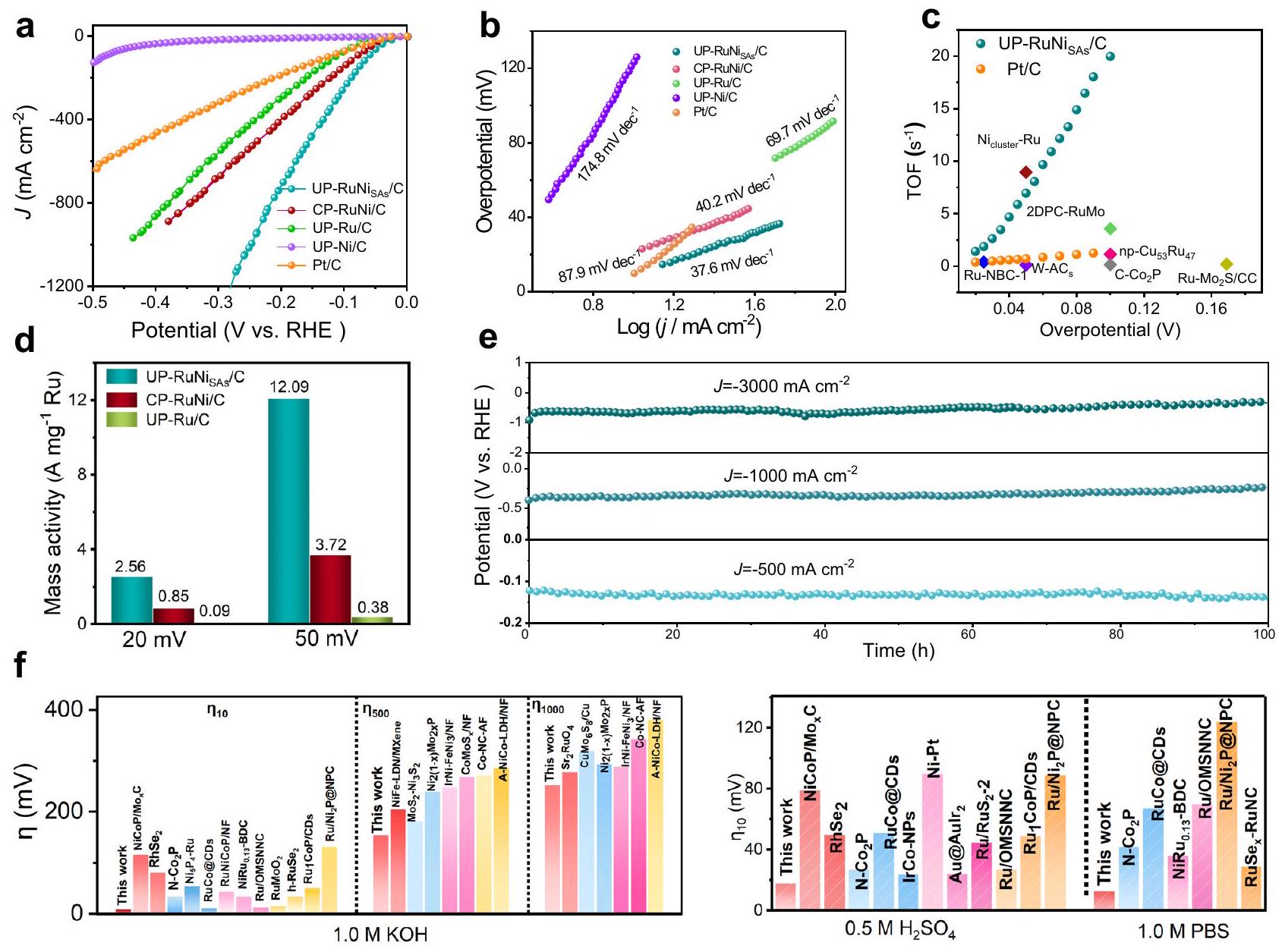
UP-RuNi was still inferior to that of UP-RuNi (Supplementary Figs. 38-40), fully demonstrating the unique advantages of carbon sites in UP-RuNi . The Tafel slope of UP-RuNi was fitted as the minimum value of (Fig. 5b) among the UP-Ru/C, UP-Ni/C, CP-RuNi/C, and commercial Pt/C, indicating its most rapid HER kinetics. Importantly, the low Tafel slope of above Ru-based materials indicates that the rate-determining step of the reaction is the desorption of the OH intermediate, rather than the water decomposition . Turnover frequency (TOF) is a critical descriptor for illustrating the intrinsic activity of catalysts. Therefore, the TOF values and number of active sites for the electrocatalysts were determined by the Cu-underpotential deposition (UPD) method (Supplementary Fig. 42a-e). As presented in Supplementary Fig. 42f, the TOF values of UP-RuNi at the overpotential of 20 mV and 50 mV were and , much higher than that of other catalysts reported thus far in this work. The TOF values of UP-RuNi compares favorably with most catalysts in Fig. 5c and Supplementary Table 7, further proving the nice intrinsic activity of UP-RuNi . Based on the respective precious metal Ru mass loading at the overpotential of 20 mV and 50 mV , we further analyzed the normalized HER activity. The UP-RuNi exhibited the highest mass activity, with a value of 12.09 A per , which is 3.3 and 31.8 times higher than CP-RuNi/C and UP-Ru/C respectively, as shown in Fig. 5d.
Electrochemical impedance spectroscopy (EIS) obtained from the corresponding equivalent circuit diagram was utilized to explore the charge transfer capacity (Supplementary Fig. 43), in which the UPRuNiSAs/C exhibited the lowest charge transfer internal resistances of and . (Supplementary Table 8), indicating the optimum conductivity of UP-RuNi towards the HER. Electrochemically active surface area (ECSA) can be used as an indicator to assess the number of active sites of catalysts. As expected, the calculated double layer capacitance ( ) value (Supplementary Fig. 44) of UP-RuNi according to the cyclic voltammetry (CV) curves at different scan rates (Supplementary Fig. 45) proved to be the highest , leading to the higher ECSA value of compared with the CP-RuNi/C ( ) and Pt/C ( ), demonstrate the ability of UP-RuNi to provide more active sites for boosting the HER performance. From the perspective of long-term stability and multiple cycle CV test, the extraordinary superiority of UP-RuNi for practical application at large current densities was further corroborated. As revealed in Supplementary Fig. 46, the LSVs of UP-RuNi before and after thousands of cycles CV demonstrate no significant changes, even when subjected to the relatively high current density. This confirms the practical applicability of UP-RuNi C, especially at large current densities. The long-term stability of industrial water electrolysis is largely limited by the current density exceeding . The UP-RuNi was subjected to chronopotentiometry test at a current density of and retained absolute stability for 200 h , superior to the commercial Pt/C electrocatalyst with the continuous decline in stability (Supplementary Fig. 47). Notably, the UP-RuNi also gave a stability for 100 h under high current densities ranging from to (Fig. 5e and Supplementary Fig. 48), demonstrating the potential for efficient and continuous response in industrial hydrogen production. In addition, the amount of produced during the first 3 h was determined via gas chromatography (Supplementary Fig. 49), demonstrating that its faradaic efficiency was nearly . The SEM (Supplementary Fig. 50) and XPS (Supplementary Fig. 51) after the electrochemical test further proved its considerable stability, with the morphology and chemical state of major elements barely changed. Moreover, the UP-RuNi also presented favorable HER performances in the acidic and neutral conditions. As shown in Supplementary Fig. 52, the UP-RuNis behaved the best activity in 0.5 M and 1.0 M phosphate buffer solution (PBS), with the smallest overpotentials of 18 mV and 27 mV , respectively, and considerable
Fig. 5 | Electrochemical performances. a, Polarization curves and Tafel plots of the UP-Ni/C, UP-Ru/C, CP-RuNi/C, UP-RuNi and commercial Pt/C catalysts in TOF values of UP-RuNi compared with and previously reported catalysts in Activity of Ru mass normalization of the UP-Ru/C, CP-RuNi/C, UP-RuNi catalysts at and in 1 M KOH . e Long term stability testing of the UP-RuNis catalysts in Comparison in terms of
overpotentials for UP-RuNi and recently reported electrocatalysts at different current densities ( and ) in 1.0 M KOH and pH-universal performance comparison of UP-RuNi and recently reported HER electrocatalysts. The catalyst loading was , the pH of the electrolyte was 13.6 , and the liquid resistance was about .
cycling and long-term stability of 28 h compared with the Pt/C (Supplementary Fig. 53b and Supplementary Fig. 55b). Finally, its pH universal and high-current-density HER activity superior to those of other reported electrocatalysts are summarized in Fig. 5f and Supplementary Table 11. All the above results demonstrate the remarkable activity of UP-RuNi at large current densities for HER and the tremendous application foreground.
To investigate the application prospect of UP-RuNi as a cathode material under actual industrial conditions, we constructed an electrolytic cell based on an anion exchange membrane. We used the commercial catalyst as the anode and compared the performance of UP-RuNi with the and catalysts separately at the cathode commercially . The AEM electrolytic cell was constructed into a sandwich configuration with an area of , consisting of a current collector, cathode (anode) catalyst, and anion membrane without hot pressing, as shown in Fig. 6a. As we expected, the performance of AEM electrolyzer based on UP-RuNi catalyst as cathode was improved as the temperature rose (Fig. 6b). Surprisingly, low cell voltage of 1.70 V and 1.95 V were recorded at and respectively at for UP-RuNis catalyst, whereas the and Pt/C and catalysts obtained the cell voltage of 1.91 V and 2.27 V separately at (Fig. 6c and Supplementary Fig. 57). More importantly, the energy conversion efficiencies for the
electrolytic cell based on UP-RuNi and catalysts are and (Fig. 6d) at . To further verify its practical application potentials in nearly the industrial scale, the long-term stability of the electrolyzer was studied for nearly 250 h at . As revealed in Fig. 6e and Supplementary Fig. 58, the UP-RuNis gave a great long-term stability with negligible potential fluctuations compared with the Pt/C and Ru/C catalysts, suggesting the promising prospect of UP-RuNi for hydrogen production.
Kinetics and reaction mechanism of the UP-RuNis for alkaline HER
As mentioned above, the low Tafel slope confirms that ratedetermining step of the reaction is the desorption of the OH intermediate. To gain further in-depth understanding on the reaction mechanism of UP-RuNi toward alkaline HER and to observe the specific adsorption (desorption) behavior of OH intermediate, we conducted CO-stripping experiment and operando Raman spectroscopy. Electrochemical oxidation of CO is triggered by adsorption of active OH , and thus the negative shift of the oxidation potential is generally considered indicative of a stronger OH affinity for the catalyst . As shown in Fig. 7a, the UP-RuNis demonstrated the lowest OH adsorption capacity with the peak potentials of 0.74 V compared with the pure UP-Ru/C ( 0.61 V ), implying the better OH
Fig. 6 | Alkaline HER performance in the AEM reactor. a Schematic illustration of the AEM reactor. LSVs operated at different cell temperatures in an AEM electrolyzer. c LSV curves of the AEM reactors using NiFeO and UP-RuNi catalysts as the anodic and cathodic electrodes, respectively at . d Cell voltage
and energy efficiency of the AEM electrolyzer at . e Stability tests of the AEM water electrolyzers at . The loading capacity of the catalyst is , the pH of the electrolyte was 13.6, and the liquid resistance was about .
desorption kinetics of Ru site in UP-RuNis with the introduction of during the Volmer step. The more negative peak potential of CP and than that of suggests that the higher OH adsorption capacity of CP-RuNi/C in Fig. 7b, which causes a decrease in water re-adsorption for the Ru site in CP-RuNi/C.
Operando Raman spectroscopy was conducted to explore the changes of surface species during alkaline HER. As presented in Fig. 7c and Supplementary Fig. 59, the OH species (at ) emerged and vanished earlier at 0.6 V vs. RHE and -0.1 V vs. RHE for UP-RuNi catalysts compared with UP-Ni/C ( 0.1 V vs. RHE and -0.6 V vs. RHE) and UP-Ru/C ( 0.4 V vs. RHE and -0.3 V vs. RHE) when the gradually reduced potentials were applied, implying the assisted Ru nanoparticles to produce OH species via water decomposition and OH desorption at a relatively positive potential . For in Fig . 7c, the relatively negative potential for OH occurrence ( 0.4 V vs. RHE) and the OH disappearance ( -0.2 V vs. RHE) further proved its inferior kinetic process for water splitting and OH desorption to that of -decorated Ru nanoparticles, and confirmed the distinctive contribution of for enhance the desorption effect of OH intermediates on Ru nanocrystal surfaces. Furthermore, the rapid desorption of bubbles at high current densities directly affects the mechanical stability of the electrode, the interaction between the catalyst and electrolyte, and ultimately affects the overall mass transmission. Rapid bubble release plays a key role in these processes . Therefore, we investigated the hydrophilicity of different materials through contact angle test. As shown in Supplementary Fig. 60, the UP-RuNi electrocatalyst gave the smallest contact angle of , significantly lower than that of UP-Ru/C ( ) and CP-RuNi/C ( ), proving the suitable hydrophilicity of UP for favorable formation of small bubbles and the release of bubbles for mass transfer.
Overall, Fig. 7d illustrates the detailed process of the entire catalytic system for promoting water decomposition and to hydrogen production. On the one hand, promote the rapid water dissociation of Ru to produce OH intermediates; on the other hand, due to the weak adsorption of on OH intermediates, are synergistically coupled to Ru with optimized kinetics in the desorption of
OH intermediates, which prevents the strong adsorption of OH intermediates by Ru. while this process is achieved through the carbon matrix as a carbon bridge, thus allowing the thermodynamic and kinetic dramatic cyclic response between the two sites.
Discussion
We reported the Ni single atom modifying ultra-small Ru nanoparticle structure (UP-RuNi ) for continuous high-current-density and pH universal hydrogen production. The catalyst could run stably for 250 h in a practical AEM electrolyzer. Anchored on carbon defects, play a crucial role in HER process, leading to an optimized adsorption kinetics of intermediates at the active site of Ru nanoparticles. This results in the effective regulation of adsorption energy and electrons environment. Specifically, the continuous re-adsorption of water molecules at the active site is ensured through synergistic adsorption of OH intermediates with . Consequently, this guarantees the continuous and efficient generation of hydrogen at high current densities. Our efforts here will not only provide a novel approach to the coordinated design of single-atom sites for effective HER catalytic systems in practical AEM electrolyzers but also highlight the importance of considering Pt-substituted electrocatalysts for other industrial-grade reactors.
Methods
Materials
Chloride hexahydrate ( ), Boric acid ( ), ammonium chloride ( ), potassium phosphate dibasic anhydrous ( ), Potassium dihydrogen phosphate , Potassium hydroxide and polyvinylpyrrolidone (PVP), ammonia were bought from Aladdin, and concentrated sulfuric acid ( ), copper sulfate pentahydrate ( ), concentrated nitric acid ( ), ethylenediaminetetraacetic acid, potassium thiocyanate acid (KSCN) and ultrapure water ( ) were purchased from China National Medicines Corporation Ltd. Ruthenium chloride hydrate ( ) was obtained from Beijing Innochem Technology Corporation Ltd. All the chemicals were used as received without any other purification.
Fig. 7 | CO-stripping experiment and operando spectroscopic characterizations. a, b CO-stripping experiment for catalyst UP-Ni/C, UP-Ru/C, and UP-RuNi obtained by UPED and CP-Ni/C, CP-Ru/C, and CP-RuNi/C obtained by CP.
d
c Operando Raman spectroscopy experiments for UP-RuNi and CP-RuNi/C. d Reaction mechanism for the UP-RuNi catalyst.
Syntheses
Synthesis of UP-RuNi . A three-electrode attached to an ECLab electrochemical workstation set-up was used to deposit electrocatalysts, with a saturated as reference electrode, a platinum wire as counter electrode, and CFP electrode ( ) as working electrode. Before electrodeposition, the clean carbon paper undergoes a pre-activation process: the clean carbon paper was firstly soaked in for 30 min , and then activated by CV in electrolyte solution for five cycles, of which the scanning range was vs. RHE. To synthesize UP-RuNi electrocatalyst, 100 mL of plating solution was prepared, which contains . The pH was adjusted to 2.7 using the , and the UP-RuNi was obtained by UPED method with pulse voltage of for 4000 times of pulses ( 8000 s ). The catalyst loading mass was decided to be .
Synthesis of UP-Ru/C and UP-Ni/C. The UP-Ru/C, UP-Ni/C electrocatalysts were synthesized by the same method with that of UP, except that without adding and to the plating solution respectively. The catalyst loading mass was decided to be .
Synthesis of UP-RuNi . The UP-RuNi was synthesized by the same method with that of UP-RuNi , except that the fresh titanium felt as working electrode.
Synthesis of CP-Ni/C, CP-Ru/C and CP-RuNi/C. In a typical preparation of CP-RuNi/C, the plating solution with the same composition with that of synthesizing UP-RuNi was prepared, and the electrocatalyst was obtained by the method of chronopotentiometry plating (CP) with constant voltage of -0.8 V (vs. ) for 8000 s , and the same method was employed to prepare the and CP , except that without adding and to the plating solution respectively. The catalyst loading mass was decided to be .
Synthesis of Pt/C catalyst. To prepare the Pt/C electrocatalyst, 20% commercial Pt/C powder was loaded on the CFP by the method of dripping with the loading mass of .
Characterization
The morphology of the catalysts was analyzed using scanning electron microscopy (SEM, 3 kV , Hitachi-SU8010), transmission electron microscopy (TEM, 200 kV , JEOL JEM 2100F) and atomic resolution aberration-corrected HAADF-STEM (FEI Titan G2 60-300). Energy dispersive X-ray spectrometry data were collected on a IXRF SDD 2610 system. XRD was carried out using a Bruker D8 Advance diffractometer with a Cu Ka radiation. ICP-OES was operated using an Agilent 5110. X-ray photoelectron spectroscopy (XPS, Thermo VG ESCALAB250) was used for analyzing surface binding energy. X-ray Absorption Structure (XAS) measurements were performed at the 4B9A beamline of the Beijing Synchrotron Radiation Facility under ring conditions of 2.2 GeV and about . The overall energy resolution
of the Ni K -edge is about 1.5 eV due to the spectrometer energy resolution of about 1.4 eV . The EXAFS data processing was carried out using the Athena and Artemis software from the IFEFFIT package . Raman data were collected using the Renishaw inVia.
Electrochemical measurements
The VMP3 electrochemical workstation was applied to conduct the HER performance of the electrocatalysts in a three-electrode system, in which a graphite rod was applied as the counter electrode, electrocatalyst deposited in situ on CFP as working electrode, and a SCE was used as the reference electrode and the reference was calibrated to the RHE with the calculation formula: . The electrode tests used electrolyte solutions of , 1.0 M PBS respectively at . The LSV test with the scan rate of was carried out after 1000 cycles of CV test at for activation and investigating the cycling stability. The chronopotentiometry was used to further investigate long-term stability of the electrocatalysts at . All the LSV curves were regulated by the -iR compensation. The ECSA was estimated by a CV method, which was carried out at different scan rates with the potential range of 0.1 V , and the calculated formulation is . The electrochemical impedance spectra (EIS) were conducted at approximately -10 mV over the frequency range from 1.0 to .
The TOF value was deliberated by the formula: . In which the I represents the corresponding current density at a certain overpotential, represents the Faraday constant ( ), n represents the number of active sites (mol) obtained by the UPD of Cu method, and is calculated by , where is the UPD copper stripping charge ( Cu upd ).
To calculate the Faraday Efficiency, we controlled a constant current density to , and the produced was quantified by gas chromatographic collection (Agilent, GC-7890B) every 30 min . The relevant calculation formula is as follows:
In which is the Faraday constant, is the amount of produced and the is the total charge passed through the cell.
Co stripping experiment
Co stripping experiment was employed to check the OH adsorption capacity of the catalysts. The working electrode was initially held at a potential of 0.1 V vs RHE in 1.0 M KOH with saturated CO for 10 min . Consequently, the CO in the solution was removed by the flow for 20 min , followed by the CO stripping CV conducted within a potential from 0 to 1.0 V vs RHE, utilizing a scan rate of .
AEM electrolyzer
The geometric area of AEM electrolyzer was . The cathode and the anode were sandwiched with the membrane to form AEM electrolyzer, in which the catalyst loading on both cathode and anode are . The hot 1.0 M KOH solution was flowed through the AEM electrolyzer with a flow velocity of . The temperature of AEM electrolyzer was measured as . The energy efficiencies reported in this work on a lower heating value of basis (LHV) are defined as:
where is the lower heating value reaction enthalpy for water electrolysis ( ). n is the measured hydrogen production rate is the current applied is the voltage applied .
Computational details
To simulate the electronic and energetic properties, we utilized first principles incorporating polarization DFT calculations with the Vienna ab initio simulation program. The calculations were conducted under the generalized gradient approximation with the Perdew-Burke-Ernzerhof formulation. Our study involved the construction of a graphene superlayer, which closely resembles the structure of . The Ru model is based on the (002) face of a hexagonal crystal. was anchored to the graphene structure by substituted C and substituted carbon defects, respectively. The vacuum spacing perpendicular to the structure plane is , and Brillouin zone integration was performed with a Monkhorst-Pack k-point mesh. The projected augmented wave potentials were chosen to describe the ionic cores and take valence electrons into account using a plane wave basis set with a kinetic energy cutoff of . Partial occupancies of the Kohn-Sham orbitals were allowed using the Methfessel-Paxton smearing method and a width of 0.2 eV . The electronic energy was considered selfconsistent when the energy change was smaller than and the weak interaction was described by DFT + D3 method using empirical correction in Grimme’s scheme .
Data availability
The study’s supporting data can be found in this article and the Supplementary Information, which are accessible upon reasonable request from the corresponding author.
References
Tour, J. M., Kittrell, C. & Colvin, V. L. Green carbon as a bridge to renewable energy. Nat. Mater. 9, 871-874 (2010).
Turner, J. A. A realizable renewable energy future. Science 285, 687-689 (1999).
Levi, P. J. et al. Macro-energy systems: toward a new discipline. Joule 3, 2282-2286 (2019).
Staffell, I. et al. The role of hydrogen and fuel cells in the global energy system. Energy Environ. Sci. 12, 463-491 (2019).
Finke, C. E. et al. Economically advantageous pathways for reducing greenhouse gas emissions from industrial hydrogen under common, current economic conditions. Energy Environ. Sci. 14, 1517-1529 (2021).
Guerra, O. J., Eichman, J., Kurtz, J. & Hodge, B.-M. Cost competitiveness of electrolytic hydrogen. Joule 3, 2425-2443 (2019).
Jin, H. et al. Molten salt-directed catalytic synthesis of 2D layered transition-metal nitrides for efficient hydrogen evolution. Chem 6, 2382-2394 (2020).
Sun, K. et al. Interfacial water engineering boosts neutral water reduction. Nat. Commun. 13, 6260 (2022).
Li, G. et al. The synergistic effect of Hf-O-Ru bonds and oxygen vacancies in for enhanced hydrogen evolution. Nat. Commun. 13, 1270 (2022).
Cao, L. et al. Identification of single-atom active sites in carbonbased cobalt catalysts during electrocatalytic hydrogen evolution. Nat. Catal. 2, 134-141 (2019).
Liu, H. et al. Dual interfacial engineering of a Chevrel phase electrode material for stable hydrogen evolution at . Nat. Commun. 13, 6382 (2022).
Yu, X. et al. “Superaerophobic” nickel phosphide nanoarray catalyst for efficient hydrogen evolution at ultrahigh current densities. J. Am. Chem. Soc. 141, 7537-7543 (2019).
Zhao, T. et al. Heterostructured V-Doped electrocatalysts for hydrogen evolution in anion exchange membrane water electrolyzers. Small 18, 2204758 (2022).
Yang, J. et al. The electronic metal-support interaction directing the design of single atomic site catalysts: achieving high efficiency
towards hydrogen evolution. Angew. Chem. Int. Ed. 133, 19233-19239 (2021).
Zhang, L., Doyle-Davis, K. & Sun, X. Pt-based electrocatalysts with high atom utilization efficiency: from nanostructures to single atoms. Energy Environ. Sci. 12, 492-517 (2019).
Yu, F.-Y. et al. Pt-O bond as an active site superior to in hydrogen evolution reaction. Nat. Commun. 11, 490 (2020).
Wang, M. et al. Site-specified two-dimensional heterojunction of Pt nanoparticles/metal-organic frameworks for enhanced hydrogen evolution. J. Am. Chem. Soc. 143, 16512-16518 (2021).
Zhang, J. et al. Single platinum atoms immobilized on an MXene as an efficient catalyst for the hydrogen evolution reaction. Nat. Catal. 1, 985-992 (2018).
Liu, Y. et al. A general route to prepare low-ruthenium-content bimetallic electrocatalysts for pH -universal hydrogen evolution reaction by using carbon quantum dots. Angew. Chem. Int. Ed. 59, 1718-1726 (2020).
Song, H. et al. Single atom ruthenium-doped CoP/CDs nanosheets via splicing of carbon-dots for robust hydrogen production. Angew. Chem. Int. Ed. 60, 7234-7244 (2021).
Yuan, S. et al. A universal synthesis strategy for single atom dispersed cobalt/metal clusters heterostructure boosting hydrogen evolution catalysis at all pH values. Nano Energy 59, 472-480 (2019).
Zhang, H., Zhou, W., Lu, X. F., Chen, T. & Lou, X. W. Implanting isolated Ru atoms into edge-rich carbon matrix for efficient electrocatalytic hydrogen evolution. Adv. Energy Mater. 10, 2000882 (2020).
Kweon, D. H. et al. Ruthenium anchored on carbon nanotube electrocatalyst for hydrogen production with enhanced Faradaic efficiency. Nat. Commun. 11, 1278 (2020).
Qiu, H. J. et al. Nanoporous graphene with single-atom nickel dopants: an efficient and stable catalyst for electrochemical hydrogen production. Angew. Chem. Int. Ed. 54, 14031-14035 (2015).
Zhu, T. et al. High-performance diluted nickel nanoclusters decorating ruthenium nanowires for pH -universal overall water splitting. Energy Environ. Sci. 14, 3194-3202 (2021).
Kumar, A. et al. Moving beyond bimetallic-alloy to single-atom dimer atomic-interface for all-pH hydrogen evolution. Nat. Commun. 12, 6766 (2021).
Xiong, Y. et al. Single-atom Rh/N-doped carbon electrocatalyst for formic acid oxidation. Nat. Nanotechnol. 15, 390-397 (2020).
Pang, B. et al. Laser-assisted high-performance PtRu alloy for pHuniversal hydrogen evolution. Energy Environ. Sci. 15, 102-108 (2022).
Gao, L. et al. Engineering a local potassium cation concentrated microenvironment toward the ampere-level current density hydrogen evolution reaction. Energy Environ. Sci. 16, 285-294 (2023).
Feng, T. et al. A highly efficient overall water splitting rutheniumcobalt alloy electrocatalyst across a wide pH range via electronic coupling with carbon dots. J. Mater. Chem. A 8, 9638-9645 (2020).
Wei, D. et al. Synthesis of N-doped graphene by chemical vapor deposition and its electrical properties. Nano Lett. 9, 1752-1758 (2009).
Sun, H. et al. S, N dual-doped carbon nanotubes as substrate to enhance the methanol oxidation performance of NiO nanoparticles. Carbon 152, 114-119 (2019).
Ding, Y. et al. Pulsed electrocatalysis enables the stabilization and activation of carbon-based catalysts towards production. Appl. Catal. B Environ. 316, 121688 (2022).
Chen, S. et al. First-principle investigation on problem of ruthenium allotropic phase stability. Chin. J. Rare Met. 39, 1095-1100 (2015).
Nanba, Y., Ishimoto, T. & Koyama, M. Structural stability of ruthenium nanoparticles: a density functional theory study. J. Phys. Chem. C 121, 27445-27452 (2017).
Philipsen, P. & Baerends, E. Cohesive energy of 3d transition metals: density functional theory atomic and bulk calculations. Phys. Rev. B 54, 5326 (1996).
Zhao, Y. et al. Anchoring sites engineering in single-atom catalysts for highly efficient electrochemical energy conversion reactions. Adv. Mater. 33, 2102801 (2021).
Lee, B.-H. et al. Reversible and cooperative photoactivation of single-atom photocatalysts. Nat. Mater. 18, 620-626 (2019).
Zhang, Y. et al. Observation of a robust and active catalyst for hydrogen evolution under high current densities. Nat. Commun. 13, 7784 (2022).
Ahmed, K. W., Jang, M. J., Habibpour, S., Chen, Z. & Fowler, M. and catalysts for anion exchange membrane water electrolysis. Electrochem 3, 843-861 (2022).
Zhang, J. et al. OH spectator at IrMo intermetallic narrowing activity gap between alkaline and acidic hydrogen evolution reaction. Nat. Commun. 13, 5497 (2022).
Li, M. et al. Proximity electronic effect of Ni/Co diatomic sites for synergistic promotion of electrocatalytic oxygen reduction and hydrogen evolution. Adv. Func. Mater. 33, 2210867 (2023).
Yunpeng, L., Weifan, S. & Zhonghua, W. Synchrotron radiation and its applications progress in inorganic materials. J. Inorg. Mater. 36, 901 (2021).
Ravel, B. & Newville, M. ATHENA, ARTEMIS, HEPHAESTUS: data analysis for X-ray absorption spectroscopy using IFEFFIT. J. Synchrotron Radiat. 12, 537-541 (2005).
Kresse, G. & Furthmüller, J. Efficiency of ab-initio total energy calculations for metals and semiconductors using a plane-wave basis set. Comput. Mater. Sci. 6, 15-50 (1996).
Kresse, G. & Furthmüller, J. Efficient iterative schemes for ab initio total-energy calculations using a plane-wave basis set. Phys. Rev. B 54, 11169 (1996).
Kresse, G. & Joubert, D. From ultrasoft pseudopotentials to the projector augmented-wave method. Phys. Rev. B 59, 1758 (1999).
Blöchl, P. E. Projector augmented-wave method. Phys. Rev. B 50, 17953 (1954).
Grimme, S., Antony, J., Ehrlich, S. & Krieg, H. A consistent and accurate ab initio parametrization of density functional dispersion correction (DFT-D) for the 94 elements H-Pu. J. Chem. Phys. 132, 154104 (2010).
Grimme, S., Ehrlich, S. & Goerigk, L. Effect of the damping function in dispersion corrected density functional theory. J. Comput. Chem. 32, 1456-1465 (2011).
Acknowledgements
We gratefully acknowledge the financial support from the National Natural Science Foundation of China (U22A20418) (J.-P.L.), (22075196) (G.L.), (21878204) (G.L.), (22250710676) (K.-A.S.) and (22102081) (K.A.S.), the Key Research and Development Program of Shanxi Province (201903D421073) (G.L.), and Research Project Supported by Shanxi Scholarship Council of China (2022-050) (G.L.).
Author contributions
R.Y. and J.L. considered and proposed the project. K.S. accomplished the DFT calculations. K.Z., Y.D., and Y.W. contributed to the electrochemical measurement. Q.Z. conducted the structural analysis. G.L., C.C., and Y.S. participated in the discussion of the data and revising the manuscript. R.Y. wrote the manuscript.
Correspondence and requests for materials should be addressed to Guang Liu, Yuhan Sun or Jinping Li.
Peer review information Nature Communications thanks the anonymous, reviewer(s) for their contribution to the peer review of this work. A peer review file is available.
College of Chemical Engineering and Technology, Shanxi Key Laboratory of Gas Energy Efficient and Clean Utilization, Taiyuan University of Technology, Taiyuan 030024, China. College of Materials Science and Engineering, Fuzhou University, Fuzhou 350108, China. Department of Chemistry, Tsinghua University, Beijing 100084, China. Shanxi Research Institute of Huairou Laboratory, Taiyuan 030031, China. Research Institute, Shanghai Tech University, Shanghai 201210, China. These authors contributed equally: Rui Yao, Kaian Sun. e-mail: liuguang@tyut.edu.cn; sunyh@sari.ac.cn; jpli211@hotmail.com