ثنائيات الباعث للضوء من البيروفسكايت الخالي من الرصاص ذات الأشعة تحت الحمراء القريبة الساطعة والمستقرة Bright and stable near-infrared lead-free perovskite light-emitting diodes

المجلة: Nature Photonics، المجلد: 18، العدد: 2
DOI: https://doi.org/10.1038/s41566-023-01351-5
تاريخ النشر: 2024-01-05

ثنائيات الباعث للضوء من البيروفسكايت الخالي من الرصاص ذات الأشعة تحت الحمراء القريبة الساطعة والمستقرة

تاريخ الاستلام: 5 أبريل 2023
تم القبول: 17 نوفمبر 2023
نُشر على الإنترنت: 5 يناير 2024
(د) التحقق من التحديثات

فانغلونغ يوان (1) جوليا فوليبيني تيانجون ليو (1) أوتكارش سينغ أنطونيلا تريجليا © جيا وي ميلفين ليم (1) يوهان كلاربرينغ سيرجي إ. سيمك إيغور أ. أبرِكُسوف © تسي تشين سوم (ب أناماريا بيتروززا (ب) وفينغ جاو

الملخص

تعتبر الصمامات الثنائية الباعثة للضوء في نطاق الأشعة تحت الحمراء القريبة ذات الأطوال الموجية الطويلة (NIR LEDs) التي تتجاوز ذروة انبعاثها 900 نانومتر ذات أهمية حيوية لمجموعة متنوعة من التطبيقات بما في ذلك الرؤية الليلية، التصوير الطبي، الاستشعار والاتصالات البصرية. ومع ذلك، فإن الإشعاع المنخفض والاستقرار التشغيلي الضعيف لأحدث تقنيات الصمامات الثنائية الباعثة للضوء في نطاق الأشعة تحت الحمراء القريبة ذات الأطوال الموجية الطويلة المستندة إلى المواد اللينة تظل من العوامل الأكثر أهمية التي تحد من تطبيقاتها العملية. هنا نقوم بتطوير صمامات ثنائية باحثة للضوء في نطاق الأشعة تحت الحمراء القريبة التي تنبعث منها أشعة تتجاوز 900 نانومتر مع تحسين الأداء من خلال التلاعب العقلاني في عملية التخصيب الإيجابي في البيروفيسكيتات القصديرية غير العضوية بالكامل. ) من خلال إبطاء والتحكم في عملية تبلور سوائل البيروفسكايت في ظروف غنية بالقصدير. تظهر مصابيح LED بالأشعة تحت الحمراء القريبة الناتجة ذروة انبعاث عند 948 نانومتر، وإشعاع عالٍ من وعمر تشغيلي نصف طويل يبلغ 39.5 ساعة عند كثافة تيار ثابتة عالية من قد تفتح عرضنا لمصادر الضوء الثابتة والفعالة من نوع NIR التي تعمل عند كثافات تيار عالية أيضًا فرصًا جديدة نحو الليزر المدفوع كهربائيًا.

تعتبر الصمامات الثنائية الباعثة للضوء في نطاق الأشعة تحت الحمراء القريبة (NIR) ذات اهتمام كبير لتطبيقات متنوعة تشمل الرؤية الليلية، التصوير الطبي، الاستشعار والاتصالات البصرية. تعتمد مصادر الأشعة تحت الحمراء القريبة في الوقت الحاضر بشكل أساسي على أشباه الموصلات غير العضوية الصلبة من النوع III-V (مثل GaAs وAllnGaAs). . ومع ذلك، فإن المعالجة القاسية والمعقدة عند درجات الحرارة العالية تزيد من تكلفتها وتحد من تكاملها في المنصات الضوئية متعددة الوظائف. لذلك، تم بذل جهود كبيرة لتطوير مصادر انبعاث ناعمة بديلة في نطاق الأشعة تحت الحمراء القريبة (NIR) يمكن أن تتغلب على هذه العيوب. على الرغم من تحقيق خطوات كبيرة في تطوير مصابيح LED في نطاق الأشعة تحت الحمراء القريبة ذات الطول الموجي القصير مع ذروة انبعاث أقل من 900 نانومتر (المراجع 7-9)، إلا أن مصابيح LED في نطاق الأشعة تحت الحمراء القريبة ذات الطول الموجي الطويل فوق 900 نانومتر المستندة إلى أشباه الموصلات العضوية ونقاط الكم الكولودية (QDs) لا تزال تواجه تحديات رئيسية تتمثل في الإشعاع المنخفض والاستقرار التشغيلي الضعيف (الجدول 1)، مما يحد من تطبيقاتها العملية. .
تعتبر البيروفسكايت المعدنية الهاليد مرشحين واعدين لمصادر الضوء LED بسبب خصائصها البصرية والكهربائية الممتازة. مبني على القصدير
الهاليد بيروفسكايت (THPs)، وخاصةً الأسود الأورثورمبيك بالكامل غير العضوي تعد واعدة للاستخدام في مصابيح LED بالأشعة تحت الحمراء بسبب فجوة الطاقة المنخفضة نقل عالي للحفر وثبات هيكلي غير عضوي داخلي ممتاز . ومع ذلك، فإن الأكسدة السهلة لـ إلى عادة ما يؤدي إلى نوع p من التوصيل مع كثافات عالية من الثقوب الخلفية، مما يؤدي إلى إعادة تركيب غير إشعاعية قوية. .
على الرغم من وجود نسبة عالية من الشوائب الموجبة في THPs، نلاحظ أن الشوائب ليست بالضرورة ضارة بأداء الجهاز، طالما يمكن التحكم في الشوائب. على سبيل المثال، تعتبر الشوائب الإلكترونية في أشباه الموصلات غير العضوية من المجموعة III-V واحدة من أقوى الأدوات في التقنيات المعتمدة، مما يسمح بضبط دقيق لوظائفها وخلق الأساس للإلكترونيات الدقيقة الحديثة. لقد تم إثبات أن الشوائب الإلكترونية المتعمدة في أشباه الموصلات يمكن أن تعزز خصائص الانبعاث نتيجة لإعادة التركيب الإشعاعي للثقوب المشوبة مع الإلكترونات الحرة. مستوحى من التطور
الجدول 1 | المعلمات الرئيسية للأداء لمصادر الضوء القريبة من الأشعة تحت الحمراء (NIR) المتطورة (>900 نانومتر) المستندة إلى أنواع مختلفة من المواد
فئة المواد وأمثلة ذروة الانبعاث (نانومتر) عرض النطاق الكامل عند نصف الحد الأقصى (نانومتر) إشعاع ) استقرار ) مرجع
الجزيئات العضوية معقدات Pt(II) 930 >200 ٤١.٦ غير متوفر 10
نقاط الكم القائمة على الرصاص PbS/PbS كوانتم دوت/ZnO ١٤٠٠ حوالي 200 9 غير متوفر 11
كوانتوم دوت PbS/بيروفسكايت 980 حوالي 150 7.4 ١٣
نقاط الكم القائمة على الفضة كوانتوم دوتس ١,٣٩٧ حوالي 75 ٨٣.٩ غير متوفر 14
هاليدات الرصاص والقصدير FPMAI-MAPb 917 حوالي 100 ٢.٧ 20
هاليدات القصدير غير العضوية 948 71 226 هذا العمل
الشكل 1|هيكل LED والأداء. أ، مخطط مستوى الطاقة. ب، EL
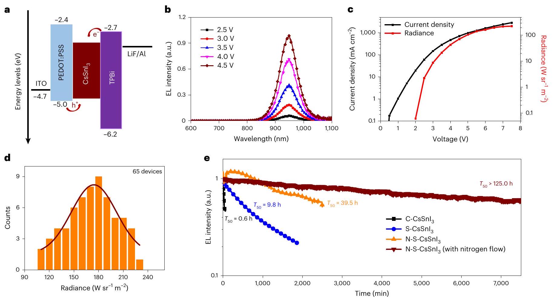
طيف عند فولتية تشغيل مختلفة. ج، د، كثافة التيار – الجهد – الإشعاع (ج) وتوزيعات الإشعاع الأقصى (د) لـ LEDs. التشغيلية
استقرار مصابيح LED المُعدة تحت ظروف مختلفة عند كثافة تيار ثابتة من استقرار N-S-CsSnI يتم قياس LEDs مع (الخط الأحمر الداكن) وبدون (الخط البرتقالي) تدفق النيتروجين للمقارنة.
لتحسين أداء LED، نعتقد أن الخصائص الداخلية للتطعيم الموجب في المواد شبه الموصلة ذات البنية غير العضوية يمكن أن تكون مفيدة لتحقيق LEDs عالية الأداء في نطاق الأشعة تحت الحمراء القريبة من خلال التحكم الدقيق في كثافات التطعيم بالثقوب والفخاخ.
هنا نبلغ عن مصابيح LED للأشعة تحت الحمراء القريبة ذات الطول الموجي الطويل التي تصل ذروتها عند 948 نانومتر مع إشعاع عالٍ وثبات تشغيلي طويل. ، تم تحقيقه من خلال استغلال التأثير المفيد للتشويب الإيجابي الداخلي في THPs وتقليل كثافة فخاخ الحاملات في الوقت نفسه. تم تطوير استراتيجية سهلة ولكن فعالة للتحكم في كثافة التشويب الإيجابي الداخلي وتقليل كثافة الفخاخ من خلال التحكم في عملية التبلور لـ المواد السابقة في ظروف غنية بالقصدير، مما يؤدي إلى تحسين الكفاءة الإشعاعية والاستقرار. من خلال الاستفادة من هذه المزايا، نعرض مصابيح LED في نطاق الأشعة تحت الحمراء القريبة مع إشعاع عالٍ من وعمر نصف تشغيلي يبلغ 39.5 ساعة عند كثافة تيار ثابتة عالية من كلاهما يتجاوز بشكل كبير مصابيح LED القائمة على المواد اللينة التي تم الإبلاغ عنها سابقًا مع قمم انبعاث تتجاوز 900 نانومتر.

هيكل الجهاز والأداء

نحن نصنع LEDات NIR القائمة على معمارية الجهاز التالية: أنود من زجاج أكسيد الإنديوم والقصدير (ITO)،
طبقة حقن الثقوب من بوليمر (3،4-إيثيلين ديوكسي ثيوفيني): بولي (ستايرين-سولفونات) (PEDOT:PSS)، نشطة طبقة الانبعاث، 1,3,5-تريس ( -فينيل بنزيميدازول-2-يل) بنزين (TPBi) طبقة نقل الإلكترون و الكاثود (الشكل 1أ). تُحضَّر الأفلام بواسطة الطلاء الدوراني من وسوائل CsI مع إضافات من N-phenylthiourea (NPTU) و (المشار إليه بـ N-S-CsSnI). لقد تم استخدامه على نطاق واسع في خلايا الشمسية المعتمدة على THP، مما يوفر حالة غنية بالقصدير لتقليل كثافة الحفر الداخلية بشكل رئيسي بسبب فراغات القصدير. يساعد NPTU في إبطاء عملية التبلور، والتي – كما سنظهر لاحقًا – تتلاعب أيضًا بكثافة الحفر الداخلية وتقلل من كثافة فخاخ الحاملات. التحكم أفلام معالجة بدون إضافات ) ومع تم إعدادها أيضًا للمقارنة. تُظهر صورة مجهر الإلكترون الماسح العرضي (الشكل التكميلي 1) للجهاز تشكيل بلورات بيروفسكايت ذات هيكل دقيق تحت الميكرومتر في طبقة الانبعاث. تم تحديد سمك فيلم البيروفسكايت ليكون حوالي ذروة انبعاث طيف الإضاءة الكهربائية (EL) لـ N-S-CsSnI تتركز LEDs في الذي تم إزاحته نحو الأحمر مقارنةً بـ و لـ C- و S-CsSnI LEDs (الشكل التوضيحي 2). بالإضافة إلى ذلك، تم تقليل العرض الكامل عند نصف الحد الأقصى (FWHM) لـ
الشكل 2 | التحضير، الشكل والخصائص الهيكلية لـ أفلام. أ، صور لـ أفلام تم إعدادها تحت ظروف مختلفة قبل وبعد التلدين، حيث تشير 0 و3 و10 دقائق إلى الأفلام قبل التلدين. ب، صور SEM لـ S-CsSnI (i)، N(5%)-S-CsSnI (ii)، N(40%)-S-CsSnI (iii) و
-S-CsSnI (iv) أفلام. قضبان القياس، . ج, طيف XRD لـ الأفلام. تم تمييز قمم الانكسار من ركيزة ITO كدوائر خضراء. د، طيف NMR للكربون لـ NPTU، NPTU + CsI، NPTU + SnI و NPTU + CsI + SnI في DMSO- حل. نسبة من أفلام تم إعدادها تحت ظروف مختلفة.
تم الحصول على 71 نانومتر لـ N-S-CsSnI LEDs، أصغر بكثير من 135 و 81 نانومتر كما هو موضح بواسطة C- و S-CsSnI LEDs، على التوالي. كما نلاحظ تحولاً ضئيلاً في طيف الإضاءة الكهربائية تحت فولتية تشغيل مختلفة (الشكل 1b والشكل التكميلي 3)، مما يدل على استقرار جيد لطيف الإضاءة الكهربائية.
N-S-CsSnI يمكن أن تعمل مصابيح LED (الشكل 1c والشكل التكميلي 4) عند كثافة تيار عالية تتجاوز ، وتظهر إشعاعًا أقصى مطابقًا لـ ، وهو أكبر بكثير من 14 و لـC وS – CsSnI LEDs (الشكل التوضيحي 5، 6). الإشعاع أيضًا أعلى بكثير من ذلك الخاص بمصادر الضوء الأخرى من نوع NIR ذات الطول الموجي الطويل مع قمم انبعاث تتجاوز 900 نانومتر، بما في ذلك المواد العضوية المعتمدة على المعادن النبيلة Pt (II)، ونقاط الكم PbS. الكوانتم دوتس والمختلط الهاليد بيروفسكايت . بالإضافة إلى ذلك، N-S-CsSnI تظهر مصابيح LED انخفاضًا منخفضًا في الكفاءة، مع الحد الأقصى للكفاءة الكمية الخارجية لـ عند إشعاع عالٍ من (الشكل التوضيحي الإضافي 4). توزيعات أقصى إشعاع وكفاءة الكم الخارجية القصوى لـ N-S-CsSnI تظهر مصابيح LED (الشكل 1d والشكل التوضيحي 7) قابلية إعادة إنتاج جيدة، مما يوضح فعالية NPTU/ استراتيجية الدمج.
تحدٍ آخر لمركبات THPs هو عدم استقرارها، مما يعيق تطبيقاتها العملية. ومن الجدير بالذكر، N-S-CsSnI تظهر مصابيح LED استقرارًا تشغيليًا طويلًا بشكل خاص مع نصف عمر ( ) من 39.5 ساعة عند كثافة تيار ثابتة تحسن بشكل كبير مقارنة بـ C-CsSnI LEDs (0.6 ساعة) و S-CsSnI LEDs (9.8 ساعة) (الشكل 1e). قيمة لـ N-S-CsSnI تمثل مصابيح LED استقرارًا قياسيًا لمصابيح LED في نطاق الأشعة تحت الحمراء القريبة (NIR) مع ذروة انبعاث تزيد عن 900 نانومتر، وهو ما يزيد بشكل ملحوظ عن مدة 3 دقائق إلى ساعة واحدة لمصابيح LED الأخرى في نطاق الأشعة تحت الحمراء القريبة التي تعمل بكثافة تيار ثابت أقل بكثير تبلغ حوالي (الجدول 1) . هذه القيمة لـ N-S-CsSnI يمكن تمديد عمر LEDs إلى 125 ساعة عند قياسها تحت تدفق نيتروجين ثابت، مما يشير إلى أن استراتيجيات إدارة الحرارة ستكون مفيدة لتحسين استقرار الجهاز بشكل أكبر.

نمو مُراقب لـ أفلام

لفهم الأسباب الكامنة وراء تحسين أداء الجهاز بعد دمج نقوم بإجراء مجموعة من التجارب للتحقيق في عمليات تشكيل الفيلم. عملية التبلور المتحكم بها والمُؤجلة لـ يتضح بوضوح (الشكل 2أ والشكل التكميلي 8). لون C – يتغير بسرعة من الأصفر الفاتح إلى البني الداكن غير المتجانس خلال 10 دقائق بعد الطلاء الدوراني (دون معالجة حرارية)، مما يدل على عملية التبلور السريعة وغير القابلة للتحكم. يتم إبطاء هذه العملية في S-CsSnI. وأيضًا تأخرت في N-S-CsSnI ، الذي يتغير من عديم اللون إلى أصفر مع شفافية عالية خلال 10 دقائق بعد الطلاء بالدوار. تظهر هذه النتائج أن الجمع بين ويمكن أن تؤخر NPTU بشكل فعال النواة وتتحكم في عملية التبلور، مما يؤدي إلى تشكيل بلورات عالية الجودة. بعد التلدين، فإن N-S-CsSnI تظهر الأفلام لون بني داكن متجانس عبر الفيلم بأكمله. كما يتضح تأثير الإضافات على التبلور من صور SEM (الشكل 2b والشكل التكميلي 9)، حيث يؤدي زيادة كمية NPTU إلى انخفاض في كثافة البلورات السطحية. بالمقارنة مع الفيلم المستمر، فإن الشكل غير المستمر مع حبيبات بيروفسكايت المعزولة في يمكن أن تعزز الأفلام كفاءة إخراج الأجهزة، كما هو موضح في LEDs القائمة على .
تكشف قياسات حيود الأشعة السينية (XRD) عن اللون الأسود هيكل جميع الأفلام (الشكل 2c). شدة القمم المميزة عند و في N-S-CsSnI تظهر تحسنًا ملحوظًا مقارنةً بتلك الخاصة بـ C – و ، مما يشير إلى تحسين البلورية (الشكل التكميلي 10) . نحن نحدد آلية التفاعل بين NPTU و يستخدم و طيف الرنين النووي المغناطيسي (NMR). إشارة الرنين لـ الناشئة من مجموعة S في NPTU تخضع لانزياح كيميائي قدره إلى و إلى
الشكل 3 | الخصائص البصرية والضوئية لـ الأفلام. أ، ب، طيف الامتصاص وطيف PL (أ) وطيف PL المحسوب زمنياً والطيف الملائم المقابل (ب) لـ الأفلام. كثافات حاملات الشحنة لـ الأفلام المحددة بواسطة قياسات تأثير هول. تشير أشرطة الخطأ إلى الأخطاء المعيارية في النتائج المحسوبة من قياس تأثير هول. د، الإثارة-
كفاءة الإضاءة المعتمدة على الكثافة لـ الأفلام. يجب الإشارة إلى أنه لقياس PLQY، تُغطى الأفلام بطبقة سميكة من PMMA، ثم تُحاط بزجاج مدعوم بمواد لاصقة تعالج بالأشعة فوق البنفسجية. وبالتالي، فإن قياس PLQY هو PLQY الخارجي، بدلاً من PLQY الداخلي.
بعد التفاعل مع و المزيج، على التوالي (الشكل 2d). تشير هذه التغيرات إلى حدوث تفاعلات كيميائية بين الـ مجموعة و . على النقيض، تحول كيميائي أصغر من من تمت ملاحظة المجموعة بعد إضافة CsI. تشير هذه المقارنة إلى أن التفاعل بين NPTU و أقوى بكثير من العلاقة بين NPTU و CsI، ويعزى ذلك إلى التفاعل الأقوى بين الحمض والقاعدة لويس و NPTU مقارنةً مع الروابط الهيدروجينية الضعيفة نسبيًا بين مجموعة و . التفاعل الأقوى بين NPTU و تم تأكيده أيضًا بواسطة بيانات التحليل الطيفي بالأشعة تحت الحمراء باستخدام تحويل فورييه مع الانعكاس الكلي المخفف (الأشكال التكميلية 11-14) .
تظهر طيف الإلكترونات السينية (XPS) المزيد من تكوين السطح لـ وتأكيد تفاعلاتها الكيميائية مع NPTU. قمة S2p في XPS لـ N-S-CsSnI ينتقل بشكل طفيف نحو طاقة ربط أعلى مقارنة بتلك الخاصة بـ NPTU النقي، مما يشير إلى انخفاض الكهربية السالبة للكبريت في N-S-CsSnI. (الأشكال التكميلية 15-17). نسبة كان مرتفعًا إلى حد ما مع شدة الذروة التي تعادل تلك لـ في C-CsSnI (الشكل 2e والشكل التكميلي 17)، مما يشير إلى الأكسدة الجادة على سطح البيروفسكايت وحدود الحبيبات. الأكسدة السهلة لـ إلى يعتبر عادةً المصدر الرئيسي لتكوين حالات الفخ في THPs. محتوى N-S-CsSnI يتم تقليله بشكل كبير مقارنةً بـ C – و S – . تشير هذه النتائج إلى أن NPTU يمكن أن يمنع أكسدة القصدير غير المرغوب فيها بسبب التفاعل القوي بين الحمض والقاعدة لويس ، مما يمكن أن يزيد من كثافة الإلكترونات حول تقدم حماية ممتازة من الأكسدة.

تحكم في نوعية الشوائب الموجبة وتقليل كثافة الفخاخ

لقد كشفت التوصيفات البصرية والفيزيائية الضوئية المفصلة أن NPTU/SnF يمكن أن يتحكم في كثافة الشوائب الموجبة ويقلل من كثافة الفخاخ . سي – سي إس سن آي يظهر نطاق امتصاص واسع مع بداية
عند وقمة انبعاث الفوتولومينسنس (PL) العريضة النطاق عند مع عرض نطاق كامل كبير يزيد عن 150 نانومتر (الشكل 3أ). على النقيض، S – و عرض ذروة الانبعاث المنزاحة نحو الأحمر مركزة عند مع قيم FWHM المخفضة البالغة 82 و 74 نانومتر، على التوالي. طيف PL الزمني المعتمد على الوقت لـ N-S-CsSnI تظهر انحلالًا أحاديًا مميزًا وزيادة في عمر الحامل يبلغ 2.28 نانوثانية مقارنةً بـ 0.49 و 1.37 نانوثانية لـ C – و على التوالي (الشكل 3ب والجدول التكميلي 1) الانزياح الأزرق وتوسع طيف الانبعاث الضوئي بالإضافة إلى عمر الحامل القصير لـ تشير إلى تركيز كبير من تراكم حاملات الشحنة الموجبة بالقرب من الحد الأقصى لفرقة التكافؤ بسبب التخصيب الذاتي القوي، والذي يمكن تفسيره بناءً على تحول بورستين-موس الديناميكي (الشكل التوضيحي 18). تشير قياسات تأثير هول إلى انخفاض كبير في كثافة التخصيب الموجب. بعد دمج و NPTU (الشكل 3c والشكل التكميلي 19)، متفقة نوعياً مع النتائج المستخلصة من قياسات طيف الإلكترونات فوق البنفسجية (الشكل التكميلي 20).
يمكن وصف ديناميات إعادة تركيب الحاملات في THPs باستخدام نموذج حركي يحاكي توليد وإعادة تركيب الحاملات الشحنية في وجود كل من التشويب والفخاخ العميقة للحاملات (الشكل التكميلي 21). من خلال تحليل نوعي لتأثير التشويب من النوع p وكثافات الفخاخ الحاملة على ديناميات إعادة تركيب الحاملات، يمكننا أن نتعلم كيف تؤثر على الأرقام القابلة للقياس مثل العائد الكمي للضوء الفوتوني الداخلي (PLQY) ومدة حياة الحاملات ( ) (مرجع 38). من خلال محاكاة الكفاءة الداخلية للإضاءة الناتجة عن كثافة الإثارة المعتمدة على كثافات حفر الشحنات من إلى وكثافات الفخاخ من إلى (الأشكال التكميلية 22-24)، نتعلم أن (1) كثافات الفخ والثقوب تلعب دورًا متنافسًا في تحديد ديناميات إعادة تركيب الحاملات والخصائص البصرية لـ ; (2) وجود حر
الشكل 4 | عمليات إعادة التركيب أوغر. أ، ب، تشتت بالقرب من أقصى نطاقات و اتباع المسار تظهر الانتقالات التمثيلية المعنية في آليات eeh أو hhe داخل كلاهما و ب باستخدام الأسهم أحادية الاتجاه. ج، د، المساحة الطورية المتاحة المحسوبة لعملية إعادة التركيب أوغر المباشرة لـ و عبر آلية eeh (c) و hhe (d) كدالة لـ -فجوة معدلة بالمقص. تمثل الخطوط العمودية المتقطعة في و فجوات النطاق التجريبية لـ (الأخضر) و (الأحمر)

ومعلمة بـ و ، على التوالي. تشير الخطوط الحمراء المتقطعة الأفقية ( ) والخضراء ( ) في و إلى قيمة -فجوة معدلة بالمقص بالنسبة لحدود النطاق التوصيلي الدنيا (eeh) أو حدود النطاق التكافلي العليا (hhe) التي يتم ملاحظة القمم في الأطياف المعنية لـ . بالنسبة لنطاق -فجوة النطاق المعدلة بالمقص في و {hhe} أكبر بحوالي أربعة أوامر من حيث الحجم مقارنة بـ {eeh}.
قد تحسن الثقوب الخلفية الناتجة عن التخصيب p من PLQY وتعزز إعادة التركيب الإشعاعي مع الإلكترونات الناتجة عن الضوء – وهذا صحيح لزيادة كثافات التخصيب حتى تصبح إعادة التركيب Auger هي السائدة؛ و (3) عندما تكون كثافة الفخاخ مشابهة أو أعلى من كثافة التخصيب، تهيمن عمليات إعادة التركيب المدفوعة بالفخاخ وتؤثر بشكل كبير على PLQY.
تم تسجيل قيم PLQY المعتمدة على كثافة الإثارة لـ الأفلام وتفسيرها بدعم من النموذج الحركي المذكور أعلاه. يظهر C-CsSnI PLQY منخفضة وثابتة في نطاق واسع من كثافات الإثارة (الشكل 3d)، والتي يمكن أن تُعزى إلى إعادة التركيب Auger الشديدة بسبب كثافة تخصيب الثقوب العالية التي تزيد عن . على العكس، تظهر S – و N-S-CsSnI PLQY محسنة في نطاق كثافة الإثارة بالكامل مع تقليل تدريجي لكثافة تخصيب الثقوب، وهو ما يظهر في ظهور عمليات ملء الفخاخ عند كثافات الإثارة المنخفضة التي تخفيها تمامًا إعادة التركيب Auger في C-CsSnI . من خلال مقارنة S- و N-S-CsSnI ، يتم تقليل كثافة الفخاخ بعد دمج NPTU، كما يتضح من التحول في زيادة PLQY الناتجة عن ملء الفخاخ نحو منطقة كثافة الإثارة المنخفضة، بالإضافة إلى PL المعتمد على درجة الحرارة (الأشكال التكميلية 25-27)، وطيف الامتصاص العابر بالفيمتو ثانية (fs-TA) (الأشكال التكميلية 28-34).

حسابات الهيكل الإلكتروني

بالنظر إلى التأثير المحتمل لكثافة تخصيب الثقوب على عملية إعادة التركيب Auger، نقوم بإجراء حسابات الهيكل الإلكتروني لفهم الآلية وراء إعادة التركيب Auger في . بهدف تسليط الضوء على الفروق بين THP ونظيره المعروف من الرصاص، نوضح العلاقة بين معدل إعادة التركيب Auger وحجم الفضاء الطوري لعمليات Auger . تكشف حسابات الهيكل الإلكتروني لـ black و أن قيمة لـ يجب أن تكون أقل بكثير مقارنة بـ ، وبالتالي، نظرًا للتشابهات بين المركبين، يجب أن تتبع معدلات إعادة التركيب نفس الاتجاه. الشكل يربط القمم في بمستويات الطاقة في هياكل النطاق لـ و . توضح الأسهم الآليات النموذجية eeh و hhe، مع تمثيل الدوائر الفارغة والمملوءة للثقوب والإلكترونات، على التوالي. تتوافق هذه الحالات الذاتية المميزة برقم و 4 مع الاتفاقية المستخدمة في المعادلة (1). نلاحظ أنه ضمن قرب معقول من extrema النطاق، فإن عدد الحالات الذاتية المتاحة، المفسرة كنقاط على نطاقات الطاقة، أكبر بكثير في حالة البيروفسكيت القائم على الرصاص مقارنة بنظيره القائم على القصدير، مما يؤدي إلى حجم فضاء طوري كبير لـ . في الوقت نفسه، تتطابق القمم في طيف (الشكل 4c,d) بشكل جيد
مع كثافة الحالات الذاتية المتاحة لعملية الثلاثة أجسام في هيكل النطاق (الشكل 4a,b). تشير هذه النتائج إلى أن ربما لديها معدل إعادة تركيب Auger أقل بكثير من . يشير حجم الفضاء الطوري الأصغر المحسوب إلى أن كثافة تخصيب الثقوب العالية في قد تكون مفيدة لخصائص انبعاث الضوء الخاصة بها. على وجه الخصوص، تم اقتراح سابقًا أن معدل إعادة التركيب Auger في المكعب يجب أن يكون أقل من ذلك في المكعب، بسبب الميزات في هيكل النطاق التي تم تحديدها أيضًا هنا من خلال حساب (المرجع 46).

المناقشات

استنادًا إلى المناقشات أعلاه، يمكننا أن نستنتج أن ربما تظهر معدل إعادة تركيب Auger أقل بكثير من ، مما يشير إلى أن خاصية التخصيب p الداخلية لـ قد تؤدي إلى تحسين PLQY بسبب إعادة التركيب الإشعاعي للثقوب الخلفية مع الإلكترونات الناتجة عن الضوء. توفر مجموعة هذه الميزات فرصًا غنية لتصنيع LEDs NIR عالية الأداء يمكن أن تعمل عند كثافات تيار عالية. وبالتالي، يمكن أن يُعزى السطوع القياسي والانخفاض المنخفض في الكفاءة لـ LEDs NIR إلى القدرة على تحمل كثافات تيار عالية تتجاوز بسبب معدل إعادة التركيب Auger المنخفض، والتحكم الدقيق في تخصيب p وكثافات الفخاخ المنخفضة التي تم تحقيقها من خلال استراتيجية الدمج لـ .
يمكن أن يُعزى تحسين استقرار الجهاز إلى ظواهر متزامنة مختلفة. أولاً، لقد أظهرنا معدل إعادة تركيب Auger أقل داخليًا لـ بالنسبة لـ . بالإضافة إلى ذلك، فإن إمكانية التحكم في تركيز تخصيب p تسمح لنا بأن نكون في حالة حيث تكون كثافة الحامل الناتجة عند صغيرة نسبيًا، بالنسبة لكثافة الثقوب الحرة، والأخيرة صغيرة بما يكفي لتعزيز إعادة التركيب الإشعاعي من النطاق إلى النطاق بدلاً من الدخول بالكامل في نظام إعادة التركيب Auger. ثانيًا، فإن حاجز الطاقة لهجرة الأيونات أكبر بكثير في THP مقارنة بنظرائه القائمين على الرصاص . من المهم ملاحظة أنه في البيروفسكيت القائم على الرصاص، تم عزو عدم الاستقرار الضوئي إلى حبس الحوامل عند عيوب عميقة بين الهاليد، مما يؤدي في النهاية إلى تكوين جزيئات وتعزيز هجرة الهاليد. ومع ذلك، لا ينطبق هذا على THPs، حيث يتم تحديد كيمياء العيوب بشكل أساسي بواسطة Sn، مما يؤدي إلى استقرار ضوئي ملحوظ حتى تحت كثافات إثارة عالية . قد يُعزى تدهور الجهاز إلى الضرر الذي يحدث عند الواجهة بين طبقة النقل وطبقة الانبعاث.

الخاتمة

باختصار، لقد أظهرنا LEDs NIR طويلة الموجة عالية السطوع والثبات تعتمد على خالية من الرصاص بالكامل. تم تطوير استراتيجية سهلة ولكن فعالة للتحكم بدقة في كثافة تخصيب p الداخلية وتقليل كثافة الفخاخ عن طريق إبطاء عملية التبلور لـ . لا تظهر LEDs NIR طويلة الموجة المعتمدة على سطوعًا عاليًا فحسب، بل تعرض أيضًا استقرارًا ممتازًا، وهو أكثر من ترتيب واحد من حيث الحجم أطول من أفضل LEDs NIR طويلة الموجة المعروفة التي تم تصنيعها مع أنواع أخرى من المواد اللينة. تعالج أعمالنا التحديات الحرجة للسطوع المنخفض والاستقرار التشغيلي الضعيف لـ LEDs NIR طويلة الموجة، مما يمثل خطوة رئيسية نحو تطبيقاتها العملية. علاوة على ذلك، يمكن توسيع الاستراتيجية للتحكم في تخصيب p وكثافات الفخاخ لتصميم THP أخرى عالية الانبعاث ومستقرة لتطبيقات انبعاث الضوء، بما في ذلك الليزر المدفوعة كهربائيًا.

المحتوى عبر الإنترنت

أي طرق، مراجع إضافية، ملخصات تقارير Nature Portfolio، بيانات المصدر، بيانات موسعة، معلومات تكميلية، شكر وتقدير، معلومات مراجعة الأقران؛ تفاصيل مساهمات المؤلفين
ومصالح متنافسة؛ وبيانات توفر البيانات والرموز متاحة على https://doi.org/10.1038/s41566-023-01351-5.

References

  1. Medintz, I. L., Uyeda, H. T., Goldman, E. R. & Mattoussi, H. Quantum dot bioconjugates for imaging, labelling and sensing. Nat. Mater. 4, 435-446 (2005).
  2. Konstantatos, G. et al. Ultrasensitive solution-cast quantum dot photodetectors. Nature 442, 180-183 (2006).
  3. Kim, S. et al. Near-infrared fluorescent type II quantum dots for sentinel lymph node mapping. Nat. Biotechnol. 22, 93-97 (2004).
  4. Sun, L. et al. Bright infrared quantum-dot light-emitting diodes through inter-dot spacing control. Nat. Nanotechnol. 7, 369-373 (2012).
  5. Yoon, J. et al. GaAs photovoltaics and optoelectronics using releasable multilayer epitaxial assemblies. Nature 465, 329-333 (2010).
  6. Walther, T., Cullis, A., Norris, D. & Hopkinson, M. Nature of the Stranski-Krastanow transition during epitaxy of InGaAs on GaAs. Phys. Rev. Lett. 86, 2381 (2001).
  7. Tuong, Ly,K. et al. Near-infrared organic light-emitting diodes with very high external quantum efficiency and radiance. Nat. Photon. 11, 63-68 (2017).
  8. Cao, Y. et al. Perovskite light-emitting diodes based on spontaneously formed submicrometre-scale structures. Nature 562, 249-253 (2018).
  9. Xu, W. et al. Rational molecular passivation for high-performance perovskite light-emitting diodes. Nat. Photon. 13, 418-424 (2019).
  10. Wei, Y. C. et al. Overcoming the energy gap law in near-infrared OLEDs by exciton-vibration decoupling. Nat. Photon. 14, 570-577 (2020).
  11. Gong, X. et al. Highly efficient quantum dot near-infrared light-emitting diodes. Nat. Photon. 10, 253-257 (2016).
  12. Pradhan, S. et al. High-efficiency colloidal quantum dot infrared light-emitting diodes via engineering at the supra-nanocrystalline level. Nat. Nanotechnol. 14, 72-79 (2019).
  13. Gao, L. et al. Efficient near-infrared light-emitting diodes based on quantum dots in layered perovskite. Nat. Photon. 14, 227-233 (2020).
  14. Vasilopoulou, M. et al. Efficient colloidal quantum dot light-emitting diodes operating in the second near-infrared biological window. Nat. Photon. 14, 50-56 (2020).
  15. Dong, Y. et al. Bipolar-shell resurfacing for blue leds based on strongly confined perovskite quantum dots. Nat. Nanotechnol. 15, 668-674 (2020).
  16. Wang, Y.-K. et al. All-inorganic quantum-dot LEDs based on a phase-stabilized perovskite. Angew. Chem. Int. Ed. 60, 16164-16170 (2020).
  17. Wang, Y.-K. et al. Chelating-agent-assisted control of quantum well growth enables stable blue perovskite emitters. Nat. Commun. 11, 3674 (2020).
  18. Zheng, X. et al. Chlorine vacancy passivation in mixed halide perovskite quantum dots by organic pseudohalides enables efficient Rec. 2020 blue light-emitting diodes. ACS Energy Lett. 5, 793-798 (2020).
  19. Wang, Z. et al. Multifunctional p-type carbon quantum dots: a novel hole injection layer for high-performance perovskite light-emitting diodes with significantly enhanced stability. Adv. Opt. Mater. 7, 1901299 (2019).
  20. Qiu, W. et al. Mixed lead-tin halide perovskites for efficient and wavelength-tunable near-infrared light-emitting diodes. Adv. Mater. 31, 1806105 (2019).
  21. Yu, H. Q. et al. Alkalis-doping of mixed tin-lead perovskites for efficient near-infrared light-emitting diodes. Sci. Bull. 67, 54-60 (2022).
  22. Lu, J. X. et al. Dendritic for efficient and flexible near-infrared perovskite light-emitting diodes. Adv. Mater. 33, 2104414 (2021).
  23. Yuan, F. et al. Color-pure red light-emitting diodes based on two-dimensional lead-free perovskites. Sci. Adv. 6, eabb0253 (2020).
  24. Wang, K. et al. Lead-free organic-perovskite hybrid quantum wells for highly stable light-emitting diodes. ACS Nano 15, 6316-6325 (2021).
  25. Liang, H. et al. High color purity lead-free perovskite light-emitting diodes via Sn stabilization. Adv. Sci. 7, 1903213 (2020).
  26. Lin, R. et al. Monolithic all-perovskite tandem solar cells with 24.8% efficiency exploiting comproportionation to suppress II oxidation in precursor ink. Nat. Energy. 4, 864-873 (2019).
  27. Lin, J. et al. Harnessing dielectric confinement on tin perovskites to achieve emission quantum yield up to . J. Am. Chem. Soc. 141, 10324-10330 (2019).
  28. Yakunin, S. et al. High-resolution remote thermometry and thermography using luminescent low-dimensional tin-halide perovskites. Nat. Mater. 18, 846-852 (2019).
  29. Hong, W. et al. Efficient low-temperature solution-processed lead-free perovskite infrared light-emitting diodes. Adv. Mater. 28, 8029-8036 (2016).
  30. Xue, S. et al. Advances in electrically driven light-emitting diodes based on lead-free metal halides. Chem. Commun. 59, 1116-1124 (2023).
  31. Wei, Q. et al. Chances and challenges for tin perovskites. Trends Chem. 4, 1-4 (2022).
  32. Chung, I. et al. : semiconductor or metal? High electrical conductivity and strong near-infrared photoluminescence from a single material. High hole mobility and phase-transitions. J. Am. Chem. Soc. 134, 8579-8587 (2012).
  33. Ricciarelli, D. et al. Instability of tin iodide perovskites: bulk p-doping versus surface tin oxidation. ACS Energy Lett. 5, 2787-2795 (2020).
  34. Li, B. et al. Tin-based defects and passivation strategies in tin-related perovskite solar cells. ACS Energy Lett. 5, 3752-3772 (2020).
  35. Barrigón, E. et al. Synthesis and applications of III-V nanowires. Chem. Rev. 119, 9170-9220 (2019).
  36. Tsintzos, S. et al. A GaAs polariton light-emitting diode operating near room temperature. Nature 453, 372-375 (2008).
  37. Feldmann, S. et al. Photodoping through local charge carrier accumulation in alloyed hybrid perovskites for highly efficient luminescence. Nat. Photon. 14, 123-128 (2020).
  38. Treglia, A. et al. Effect of electronic doping and traps on carrier dynamics in tin halide perovskites. Mater. Horiz. 9, 1763-1773 (2022).
  39. Zhang, X. et al. First-principles simulation of carrier recombination mechanisms in halide perovskites. Adv. Eng. Mater. 10, 1902830 (2020).
  40. Meng, X. et al. Crystallization kinetics modulation of FASnI films with pre-nucleation clusters for efficient lead-free perovskite solar cells. Angew. Chem. Int. Ed. 60, 3693-3698 (2021).
  41. Wang, S. et al. High-performance perovskite solar cells with large grain-size obtained by using the Lewis acid-base adduct of thiourea. Sol. RRL 2, 1800034 (2018).
  42. Guo, Q. et al. Passivation of the grain boundaries of using carbon quantum dots for highly efficient perovskite solar cells with excellent environmental stability. Nanoscale 11, 115-124 (2019).
  43. Ye, T. et al. Ambient-air-stable lead-free solar cells with greater than 7.5% efficiency. J. Am. Chem. Soc. 143, 4319-4328 (2021).
  44. Milot, R. et al. The effects of doping density and temperature on the optoelectronic properties of formamidinium tin triiodide thin films. Adv. Mater. 30, 1804506 (2018).
  45. Bubnova, O. et al. Semi-metallic polymers. Nat. Mater. 13, 190-194 (2014).
  46. Shen, J. et al. Unexpectedly strong Auger recombination in halide perovskites. Adv. Energy Mater. 8, 1801027 (2018).
  47. Martani, S. et al. Defect engineering to achieve photostable wide bandgap metal halide perovskites. ACS Energy Lett. 8, 2801-2808 (2023).
Publisher’s note Springer Nature remains neutral with regard to jurisdictional claims in published maps and institutional affiliations.
Open Access This article is licensed under a Creative Commons Attribution 4.0 International License, which permits use, sharing, adaptation, distribution and reproduction in any medium or format, as long as you give appropriate credit to the original author(s) and the source, provide a link to the Creative Commons license, and indicate if changes were made. The images or other third party material in this article are included in the article’s Creative Commons license, unless indicated otherwise in a credit line to the material. If material is not included in the article’s Creative Commons license and your intended use is not permitted by statutory regulation or exceeds the permitted use, you will need to obtain permission directly from the copyright holder. To view a copy of this license, visit http://creativecommons. org/licenses/by/4.0/.
© The Author(s) 2024

طرق

المواد

المواد الكيميائية المدرجة أدناه متاحة تجاريًا وتستخدم دون مزيد من التنقية. تم شراء يوديد القصدير ( )، فلوريد القصدير ( ، 99.000%)، يوديد السيزيوم (CsI، 99.999%) و NPTU (>98.000%) من Sigma-Aldrich. تم شراء PEDOT:PSS (AI 4083) من Ossila. تم شراء جميع المواد الأخرى المستخدمة في تصنيع الجهاز من Sigma-Aldrich.

حسابات الهيكل الإلكتروني

تم إجراء حسابات الهيكل الإلكتروني لـ black و باستخدام حزمة المحاكاة Vienna ab initio باستخدام طريقة الموجة المعززة بالمشاريع. تم استخدام الوظيفة PBEsol في إطار نظرية الوظيفة الكثافة لتحسين الهندسة، بينما تم تنفيذ الوظيفة الهجينة HSE مع 50% من تبادل Hartree-Fock الدقيق للتفاعلات قصيرة المدى ومعامل تصفية قدره لتقييم هيكل النطاق. نحن نستخدم تبادل هارتري-فوك الدقيق حيث يوفر أفضل توافق بين هياكل النطاق HSE وGW، حيث يتطلب الأخير تكلفة حسابية عالية جدًا لعينات كثيفة من منطقة بريلوان، وهو أمر ضروري لحساب قيم ذات مغزى من لأخذ التأثيرات النسبية في الاعتبار بالكامل، تم تضمين تفاعل الدوران-المدار في جميع الحسابات.

تحضير محلول الأفلام البيروفيسكية

محلول سلف التحكم بدون إضافات (المشار إليه بـ تم تحضيره عن طريق إذابة و 73 ملغ من CsI في 1 مل من DMSO (0.3 م: تم تحديد التركيز بناءً على محتوى Sn). محلول السلف هو (المشار إليه بـ تم تحضيره عن طريق إذابة CsI و في 1 مل من DMSO (0.3 م، تم تحضير محلول NPTU عن طريق إذابة 152 ملغ من NPTU في 1 مل من DMSO (1 م). أما بالنسبة لمحلول السلف المضاف إليه NPTU، فقد تم إضافة كمية معينة من NPTU (1 م) في S-CsSnI. محلول سابق لتحقيق التركيبة المرغوبة (المشار إليه بـ N-S-CsSnI تم تحريك المحلول وتصفيته قبل الطلاء بالطرد المركزي. طبقات الانبعاث لـ مع تركيبات مختلفة تم طلاءها بالطرد المركزي في صندوق قفازات مملوء بالنيتروجين (تركيزات من و ) من خلال عملية من خطوتين، 1000 دورة في الدقيقة لمدة 10 ثوانٍ (سرعة التسارع، ) ثم 5000 دورة في الدقيقة لمدة 60 ثانية (سرعة التسارع، )، تليها عملية التلدين عند لمدة 10 دقائق لتشكيل طبقة الانبعاث النشطة. كانت نسبة الشوائب المثلى لـ NPTU هي 40% (نسبة مولية مقارنة بـ Sn). بالنسبة لـ PL، PL المعتمد على درجة الحرارة المنخفضة، PL المعتمد على الزمن، طيف الامتصاص فوق البنفسجي-المرئي، طيف fs-TA وقياسات XRD، تم طلاء محلول بوليميثيل ميثاكريلات (PMMA)/كلوروبنزين بواسطة الدوران بسرعة 6000 دورة في الدقيقة لمدة 50 ثانية على سطح طبقة البيروفسكايت.

التحليل البصري

تم قياس طيف الامتصاص فوق البنفسجي-المرئي باستخدام جهاز بيركين إلمر طراز LAMBDA 900a. تم إجراء قياسات الطيف الضوئي الثابت الحالة على مطياف أندور شامروك 303i المزود بجهاز أندور نيوتن للكشف عن الشحنات المعززة (DU970N-UVB). خلال القياس، تم تبريد كاشف جهاز الكشف عن الشحنات المعززة إلى . تم تحفيز العينة بواسطة وحدة ليزر DPSS مضخة بالديود الليزري من ثورلابس (CPS532)، وتم استخدام فلتر تمرير طويل بطول موجي 550 نانومتر لحماية الكاشف. تم معايرة طول موجة النظام بواسطة مصباح زئبقي. تم معايرة شدة الطيف بواسطة مصباح هالوجين قياسي (AvaLight-HAL-S-Mini) من أفانتس. ليزر ( تم استخدام (عرض النبضة) كمصدر تحفيز بمعدل تكرار 10 ميجاهرتز (أدوات إدنبرة) لقياس طيف PL الزمني. تم تركيز الليزر على العينة بواسطة عدسة هوائية (فتحة عددية، 0.7؛ حجم البقعة، ; ميتوتويو). تم جمع بيانات PL للعينة بواسطة نفس العدسة وتم إرسالها إلى كاشف فوتوني من نوع أفالانش (دقة التوقيت، ; ID Quantique) في زمن مرتبط
نظام عدّ الفوتونات المفردة (تذبذب التوقيت، ps; qutools) مع دالة استجابة الأداة لـ تم الحصول على قيم PLQY المعتمدة على الشدة من خلال تركيز التوافقي الثاني لليزر Yb:KGW (Light Conversion Pharos، مدة النبضة، تردد تكرار 1 كيلو هرتز) على الأفلام الرقيقة من ضمن نطاق الفلونس بين و ، وجمع الانبعاث الضوئي (PL) على مطياف الألياف (Ocean Optics Maya Pro 2000). تم معايرة قياسات PLQY النسبية عن طريق ضبط منحنى PLQY الناتج على قياس PLQY المطلق الذي تم إجراؤه في كرة دمج (Labsphere). بالنسبة لقياس PLQY، فإن تم تغليف الأفلام بطبقة سميكة من PMMA، ثم تم encapsulated بزجاج مدعوم بلصق curing بالأشعة فوق البنفسجية.

طيف الانبعاث الضوئي المعتمد على درجة الحرارة المنخفضة

تم تثبيت العينات في جهاز تبريد مغلق الدورة (DE-202AE) من أنظمة البحث المتقدمة. تم التبريد بواسطة ضاغط هيليوم (ARS-4HW) من نفس الشركة. تم التحكم في درجة الحرارة بواسطة جهاز تحكم في درجة الحرارة ذاتي الضبط من Lake Shore 330. خلال القياس، تم الاحتفاظ بجهاز التبريد في فراغ. تم تنفيذ تحفيز واكتشاف PL بواسطة عدسة، زجاج ثنائي اللون بزاوية 552 نانومتر وطويل الموجة وألياف بصرية. تم توصيل ضوء الليزر إلى الألياف، خارجاً من جهاز التوازي، ثم تم عكسه بواسطة الزجاج وأخيراً تم تركيزه بواسطة العدسة إلى داخل الكريوستات. مرت الانبعاثات من العينة عبر نافذة الكريوستات، العدسة، الزجاج، جهاز التوازي، الألياف، جهاز التوازي مرة أخرى وأخيراً تم تركيزها في الطيف الضوئي.

قياس fs-TA

تم إجراء طيفية fs-TA باستخدام مطياف HELIOS fs-TA (أنظمة فائقة السرعة). تم أخذ جزء من الناتج الأساسي بزاوية 800 نانومتر من المعزز المتجدد (Coherent Libra، ) تم استخدامه لضخ مضخم بصري برامترى (Coherent OPerA Solo). تم توليد نبضات الضخ بطول موجي 650 نانومتر من مضخم بصري برامترى. تم تركيز جزء آخر من الشعاع الأساسي بطول موجي 800 نانومتر في بلورة ياقوتية بطول 10 مم لتوليد استمرارية واسعة النطاق في الأشعة تحت الحمراء القريبة ( ) الذي تم استخدامه كنبضة استكشافية. تم تمرير شعاع الاستكشاف من خلال فلتر تمرير طويل بطول 850 نانومتر لإزالة المكونات الأساسية المتبقية عند 800 نانومتر لمنع الإثارة الضوئية الثانوية القوية للعينة. تم جمع الإشارات باستخدام مستشعر من أشباه الموصلات المعدنية-أكسيد المكمل داخل الطيف.

قياسات هول

تم إجراء قياسات هول في شريحة ذات هندسة فان دير باو. تم ترسيب الأقطاب الكهربائية الأربعة السفلية باستخدام الكروم والذهب. تم تغليف الأفلام بـ PMMA لتجنب التدهور. تم وضع الرقائق عموديًا على المجال المغناطيسي الذي يتغير من -1.2 إلى 1.2 تسلا. تم تسجيل التيار والجهد المطبقين بواسطة أجهزة كيثلي 2400 ونانوفولتميتر طراز 2182A، على التوالي. تم إجراء جميع القياسات في الهواء عند درجة حرارة الغرفة.

الخصائص الهيكلية والشكلية والكيميائية

تم إجراء قياسات حيود الأشعة السينية باستخدام جهاز حيود الأشعة السينية (PANalytical X’Pert Pro) مع أنبوب أشعة سينية ( Åتم إجراء قياسات الانعكاس الكلي المخفف باستخدام تحويل فورييه للأشعة تحت الحمراء على ملحق PIKE MIRacle للانعكاس الكلي المخفف مع منشور ماسي في مطياف Vertex 70 (Bruker) باستخدام كاشف DLATGS في درجة حرارة الغرفة. تم الحصول على الأطياف عند الدقة. تم إجراء SEM باستخدام جهاز Philips XL30 FEG SEM تحت جهد 8 كيلو فولت. بروتون الرنين المغناطيسي النووي (500 ميغاهرتز) والكربون ( تم تسجيل (NMR (126 ميغاهيرتز على جهاز طيفي من نوع فارين 500 ميغاهيرتز في درجة حرارة الغرفة. تم تجفيف DMSO- تم استخدامه كمذيب ولمعايرة الانزياحات الكيميائية الأيزوتوبية في NMR. XPS (أشعة سينية مونوكروماتية AI K تم تسجيل الأطياف باستخدام محلل نصف كروي Scienta 200 وتم معايرته
من خلال الإشارة إلى مستوى فيرمي وموقع قمة Au4f7/2 لـ تنظيف الذهب باستخدام رذاذ الأيونات.

تصنيع الأجهزة وتوصيفها

تم تنظيف ركائز الزجاج المطلية بـ ITO عن طريق التنظيف بالموجات فوق الصوتية في الماء المنزوع الأيونات ثم في المذيبات العضوية (الأسيتون يليه الإيثانول)، ثم تم تجفيفها تحت تدفق النيتروجين. تم تنظيف الركائز باستخدام معالجة البلازما فوق البنفسجية لتغني سطح ITO بالأكسجين وزيادة وظيفة عمل ITO. تم طلاء طبقة حقن الثقوب PEDOT:PSS باستخدام تقنية الدوران بسرعة 4000 دورة في الدقيقة (سرعة التسارع، 4000 دورة في الدقيقة في الثانية). ) لمدة 40 ثانية على ITO تليها معالجة حرارية في الهواء عند لمدة 30 دقيقة، ثم تم ترسيب الأفلام على PEDOT:PSS في صندوق قفازات مملوء بالنيتروجين. أخيرًا، تم نقل الركائز إلى غرفة فراغ، حيث تم وضع طبقات TPBi (55 نانومتر) وأقطاب LiF/Al. تم ترسيبها باستخدام نظام تبخر حراري من خلال قناع ظل تحت فراغ عالي من تور. كانت المنطقة النشطة للجهاز كما هو محدد من خلال المنطقة المتداخلة بين أقطاب ITO و Al. تم قياس أداء LEDs في صندوق قفازات مملوء بالنيتروجين عند درجة حرارة الغرفة. تم استخدام مقياس مصدر Keithley 2400 وكرة تكامل الألياف (FOIS-1) المرتبطة بمطياف QE Pro (Ocean Optics) لقياسات LED. يجب ملاحظة أن إعداد LED الخاص بنا تم برمجته لقياس طيف EL الذي يتراوح من 350 إلى 930 نانومتر. لذلك، فإن طيف EL الكامل حتى تم الحصول عليها بعد ذلك من مقياس الطيف الآخر (شامروك 303i؛ الكاشف هو جهاز مضاعف الشحنات الإلكتروني أندور نيوتن) مع نطاق واسع من الكشف عن الانبعاث مدفوعًا بجهاز قياس مصدر كيثلي 2400، وبالتالي تم معايرة الأداء من خلال مقارنة طيف EL المقاس في إعداد LED ومن شامروك 303i. تم قياس استقرار LED إما في صندوق القفازات في مساحة صغيرة محصورة (بدون تدفق نيتروجين) أو في صندوق مصنوع يدويًا مملوء بالنيتروجين في درجة حرارة الغرفة مع تدفق نيتروجين، كما هو موضح في الأشكال. تم تشغيل الأجهزة بواسطة جهاز قياس مصدر كيثلي 2400 عند تيار ثابت وتم قياس إشارات انبعاث الضوء باستخدام ثنائي ضوئي تجاري.

توفر البيانات

البيانات التي تدعم نتائج هذه الدراسة متاحة من المؤلف المراسل عند الطلب المعقول.

الشكر والتقدير

نشكر ب. جوان و ل. ليانغ من معهد الكيمياء، الأكاديمية الصينية للعلوم، على قياس SEM العرضي؛ هـ. زانغ على المساعدة في قياسات EL و PL وطيف PL المعتمد على درجة الحرارة المنخفضة؛ ز. هو و ج. زانغ على قياس طيف NMR؛ ج. وانغ على قياسات XPS وطيف الإلكترون الضوئي فوق البنفسجي؛ هـ. لي على توصيف SEM؛ ج. كوانغ على قياس طيف الأشعة تحت الحمراء بواسطة تحويل فورييه؛ و ل. سوي على المساعدة في محاكاة ديناميات إعادة تركيب الحاملات. يقر F.Y. بالدعم المالي من البرنامج الوطني الرئيسي للبحث والتطوير في الصين (2023YFB3611800)، ومؤسسة العلوم الطبيعية الوطنية في الصين (22302012)، وصندوق العلوم الوطنية للعلماء الشباب المتميزين (الخارجيين) وصناديق خاصة لجذب المواهب من جامعة بكين نورمال (312200502508). يقر F.G. بالدعم من مؤسسة كنوت وأليس والينبرغ.
المؤسسة (Dnr. KAW 2019.0082)، منحة مجلس البحث الأوروبي الموحد (LEAP، 101045098)، مجلس البحث السويدي (منحة 2020-03564) ومنطقة البحث الاستراتيجية الحكومية السويدية في علوم المواد حول المواد الوظيفية في جامعة لينشوبينغ (منحة الكلية SFO-Mat-LiU رقم 2009-00971). I.A.A. هو عالم أكاديمية والينبرغ (رقم المنحة KAW-2018.0194). يقر S.I.S. بالدعم من مجلس البحث السويدي (VR) (رقم المشروع 2019-05551) و ERC (منحة التآزر لمشروع FASTCORR 854843). يقر T.C.S. و J.W.M.L. بالدعم من وزارة التعليم في سنغافورة بموجب منحة MOE Tier 2 (MOE-T2EP50120-0004) ومن مؤسسة البحث الوطنية (NRF) في سنغافورة بموجب منحة NRF Investigatorship (NRF-NRFI2018-04). يقر A.P. و G.F. و A.T. بالتمويل من برنامج البحث والابتكار Horizon 2020 للاتحاد الأوروبي من خلال مشروع ERC SOPHY بموجب اتفاقية المنحة رقم 771528، و MSCA-ITN SMART-X بموجب اتفاقية المنحة رقم 860553 ومنحة ماري سكلودوفسكا-كوري بموجب اتفاقية المنحة رقم 956270. تم تمكين الحسابات من خلال الموارد المقدمة من البنية التحتية الأكاديمية الوطنية للحوسبة الفائقة في السويد (NAISS) والبنية التحتية الوطنية السويدية للحوسبة (SNIC) في المركز الوطني للحوسبة الفائقة (NSC) ومركز الحوسبة عالية الأداء (PDC)، الممول جزئيًا من قبل مجلس البحث السويدي من خلال اتفاقيات المنحة رقم 2022-06725 و 2018-05973.

مساهمات المؤلفين

F.G. و F.Y. وضعوا الفكرة وصمموا التجارب. F.Y. أعدت العينات وأجرت تصنيع الأجهزة والقياسات. F.Y. و G.F. و A.T. و A.P. أجروا محاكاة ديناميات إعادة تركيب الحاملات وقياس PLQY. ساعد T.L. في استقرار الجهاز وقياس تأثير هول. قام J.W.M.L. و T.C.S. بإجراء قياسات fs-TA. أجرى U.S. و J.K. و S.I.S. و I.A.A. الحسابات النظرية. كتبت F.Y. المسودة الأولى من الورقة. ناقش جميع المؤلفين النتائج وساهموا في الورقة.

التمويل

تم توفير تمويل الوصول المفتوح من قبل جامعة لينشوبينغ.

المصالح المتنافسة

F.Y. و F.G. يقومان بتقديم طلب براءة اختراع يتعلق بهذا العمل.

معلومات إضافية

المعلومات التكميلية النسخة على الإنترنت تحتوي على مواد تكميلية متاحة في https://doi.org/10.1038/s41566-023-01351-5.
يجب توجيه المراسلات والطلبات للحصول على المواد إلى فنغ غاو.
معلومات مراجعة الأقران تشكر Nature Photonics المراجعين المجهولين على مساهمتهم في مراجعة الأقران لهذا العمل.
معلومات إعادة الطباعة والتصاريح متاحة في www.nature.com/reprints.

  1. قسم الفيزياء والكيمياء وعلم الأحياء (IFM)، جامعة لينشوبينغ، لينشوبينغ، السويد. المختبر الرئيسي للكيمياء الضوئية النظرية والحسابية بوزارة التعليم، كلية الكيمياء، جامعة بكين نورمال، بكين، الصين. مركز العلوم والتكنولوجيا النانوية@بوليمي، المعهد الإيطالي للتكنولوجيا، ميلانو، إيطاليا. قسم الفيزياء، بوليتكنيكو دي ميلانو، ميلانو، إيطاليا. قسم الفيزياء والفيزياء التطبيقية، مدرسة العلوم الفيزيائية والرياضية، جامعة نانيانغ التكنولوجية، سنغافورة، سنغافورة. قسم الفيزياء وعلم الفلك، جامعة أوبسالا، أوبسالا، السويد. البريد الإلكتروني: feng.gao@liu.se

Journal: Nature Photonics, Volume: 18, Issue: 2
DOI: https://doi.org/10.1038/s41566-023-01351-5
Publication Date: 2024-01-05

Bright and stable near-infrared lead-free perovskite light-emitting diodes

Received: 5 April 2023
Accepted: 17 November 2023
Published online: 5 January 2024
(D) Check for updates

Fanglong Yuan (1) , Giulia Folpini , Tianjun Liu (1) , Utkarsh Singh , Antonella Treglia © , Jia Wei Melvin Lim (1) , Johan Klarbring , Sergei I. Simak , Igor A. Abrikosov © , Tze Chien Sum (B , Annamaria Petrozza (B ) & Feng Gao

Abstract

Long-wavelength near-infrared light-emitting diodes (NIR LEDs) with peak emission wavelengths beyond 900 nm are of critical importance for various applications including night vision, biomedical imaging, sensing and optical communications. However, the low radiance and poor operational stability of state-of-the-art long-wavelength NIR LEDs based on soft materials remain the most critical factors limiting their practical applications. Here we develop NIR LEDs emitting beyond 900 nm with improved performance through the rational manipulation of p doping in all-inorganic tin perovskites ( ) by retarding and controlling the crystallization process of perovskite precursors in tin-rich conditions. The resulting NIR LEDs exhibit a peak emission wavelength at 948 nm , high radiance of and long operational half-lifetime of 39.5 h at a high constant current density of . Our demonstration of efficient and stable NIR LEDs operating at high current densities may also open up new opportunities towards electrically pumped lasers.

Near-infrared (NIR) light-emitting diodes (LEDs) are of great interest for diverse applications including night vision, biomedical imaging, sensing and optical communications . Present-day NIR emitters primarily rely on III-V epitaxial hard inorganic semiconductors (such as GaAs and AllnGaAs) . However, the harsh and complicated high-temperature processing increases their cost and limits their integration in multifunctional photonic platforms. Therefore, great efforts have been made to develop alternative soft NIR emitters that can overcome these drawbacks. Although substantial strides have been made for short-wavelength NIR LEDs with emission peak below 900 nm (refs. 7-9), long-wavelength NIR LEDs over 900 nm based on organic semiconductors and colloidal quantum dots (QDs) still face primary challenges of low radiance and poor operational stability (Table 1), limiting their practical applications .
Metal halide perovskites are promising candidates for LEDs due to their excellent optical and electrical properties . Tin-based
halide perovskites (THPs), especially all-inorganic black orthorhombic , are promising for use in NIR LEDs due to their low bandgap ( ), high hole mobilities and excellent intrinsic inorganic structural stability . However, the easy oxidation of to usually results in p doping with high background hole densities, leading to strong non-radiative recombinations .
In spite of the strong p doping in THPs, we notice that doping is not necessarily detrimental towards device performance, as long as the doping can be controlled. For example, electronic doping in conventional III-V-group inorganic semiconductors is one of the most powerful tools in established technologies, allowing for the fine-tuning of their functionalities and creating the base for modern microelectronics. It has been demonstrated that intentional electronic doping in semiconductors could boost emission properties as a result of the radiative recombinations of doped holes with free electrons . Inspired by the development
Table 1 | Key performance parameters of state-of-the-art NIR LEDs (>900 nm) based on different kinds of material
Materials category and examples Emission peak (nm) FWHM (nm) Radiance ( ) Stability ( ) Ref.
Organic molecules Pt(II) complexes 930 >200 41.6 NA 10
Pb-based QDs PbS/PbS QD/ZnO 1,400 ~200 9 NA 11
PbS QD/perovskite 980 ~150 7.4 13
Ag-based QDs QDs 1,397 ~75 83.9 NA 14
Lead-tin halides FPMAI-MAPb 917 ~100 2.7 20
Inorganic tin halides 948 71 226 This work
Fig. 1|LED structure and performance. a, Energy-level diagram. b, The EL
spectra at different operating voltages. c,d, Current density-voltage-radiance (c) and histograms of maximum radiance (d) of LEDs. e, Operational
stability of LEDs prepared under different conditions at a constant current density of . The stability of N-S-CsSnI LEDs are measured with (dark red line) and without (orange line) a nitrogen flow for comparison.
of electronic doping in inorganic semiconductors for improved LED performance, we, thus, believe that the intrinsic p-doping characteristic of THPs could be beneficial for achieving high-performance NIR LEDs through elaborately controlling the hole-doping and trap densities.
Here we report long-wavelength NIR LEDs peaking at 948 nm with high radiance and long operational stability based on , achieved by simultaneously exploiting the beneficial effect of intrinsic p doping in THPs and reducing the carrier trap density. A facile yet effective strategy is developed to control the intrinsic p-doping density and reduce the trap density by controlling the crystallization process of precursors in tin-rich conditions, leading to improved radiative efficiency and stability. Leveraging these benefits, we demonstrate NIR LEDs with a high radiance of and an operational half-lifetime of 39.5 h at a high constant current density of , both significantly exceeding the previously reported soft-materials-based NIR LEDs with emission peaks over 900 nm .

Device structure and performance

We fabricate -based NIR LEDs with the following device architecture: indium tin oxide (ITO) glass substrate anode, a
poly(3,4-ethylenedioxythiophene):poly(styrene-sulfonate) (PEDOT:PSS) hole injection layer, an active emission layer, a 1,3,5-tris ( -phenylbenzimidazol-2-yl) benzene (TPBi) electron transport layer and a cathode (Fig. 1a). films are prepared by spin coating from and CsI precursors with additives of N -phenylthiourea (NPTU) and (denoted as N-S-CsSnI). has been widely used in THP-based solar cells, providing a tin-rich condition to reduce the intrinsic hole-doping density mainly due to Sn vacancies. NPTU helps to retard the crystallization process, which-as we show later-further manipulates the intrinsic p-doping density as well as reduces the carrier trap density. Control films treated without additives ( ) and with are also prepared for comparison. A cross-sectional scanning electron microscopy (SEM) image (Supplementary Fig. 1) of the device shows the formation of discrete submicrometre-structured perovskite crystals in the emission layer. The thickness of the perovskite film was determined to be around . The emission peak of the electroluminescence (EL) spectra of N-S-CsSnI LEDs is centred at , which is redshifted compared with that of and for C- and S-CsSnI LEDs (Supplementary Fig. 2). In addition, a reduced full-width at half-maximum (FWHM) of
Fig. 2 | Preparation, morphology and structural characterizations of films. a, Photographs of films prepared under different conditions before and after annealing, where 0,3 and 10 min indicate the films before annealing. b, SEM images of S-CsSnI (i), N(5%)-S-CsSnI (ii), N(40%)-S-CsSnI (iii) and
-S-CsSnI (iv) films. Scale bars, . c, XRD spectra of films. The diffraction peaks from the ITO substrate are marked as green cycles. d, C NMR spectra of NPTU, NPTU + CsI, NPTU + SnI and NPTU + CsI + SnI in a DMSO- solution. e, Proportion of of films prepared under different conditions.
71 nm is obtained for N-S-CsSnI LEDs, much smaller than 135 and 81 nm shown by C- and S-CsSnI LEDs, respectively. We also observe a negligible shift in the EL spectra under different operating voltages (Fig. 1b and Supplementary Fig. 3), demonstrating good EL spectral stability.
The N-S-CsSnI LEDs (Fig. 1c and Supplementary Fig. 4) can operate at a high current density of over , and show a corresponding maximum radiance of , which is much larger than that of 14 and forC-andS-CsSnI LEDs (Supplementary Fig.5,6). The radiance is also much higher than that of other long-wavelength NIR LEDs with emission peaks over 900 nm , including noble-metal Pt (II)-based organic materials, PbS QDs, QDs and mixed halide perovskites . In addition, the N-S-CsSnI LEDs show a low efficiency roll-off, with the maximum external quantum efficiency of at a high radiance of (Supplementary Fig. 4). The maximum radiance and peak external quantum efficiency histograms of N-S-CsSnI LEDs (Fig. 1d and Supplementary Fig. 7) show good reproducibility, demonstrating the effectiveness of the NPTU/ incorporation strategy.
Another challenge for THPs is their poor stability, which hinders their practical applications. Notably, N-S-CsSnI LEDs exhibit a particularly long operational stability with a half-lifetime ( ) of 39.5 h at a constant current density of , greatly improved compared with C-CsSnI LEDs ( 0.6 h ) and S-CsSnI LEDs ( 9.8 h ) (Fig. 1e). The value for N-S-CsSnI LEDs represents the record stability for NIR LEDs with an emission peak of over 900 nm , significantly longer than that of 3 min to 1 h for other NIR LEDs operating at a much smaller constant current density of around (Table1) . This value for N-S-CsSnI LEDs can be extended to 125 h when measured under a constant nitrogen flow, indicating that strategies on thermal management would be helpful to further improve the device stability.

Controlled growth of films

To understand the underlying reasons for improved device performance after the incorporation of , we perform a range of experiments to investigate the film formation processes. The controlled and retarded crystallization process of is clearly revealed (Fig. 2a and Supplementary Fig. 8). The colour of C – quickly changes from light yellow to inhomogeneous dark brown within 10 min after spin coating (without annealing), indicating the fast and uncontrollable crystallization process. This crystallization process is slowed down inS-CsSnI and further retarded in N-S-CsSnI , which changes from colourless to yellow with high transparency within 10 min after spin coating. These results demonstrate that the combination of and NPTU could effectively retard the nucleation and control the crystallization process, leading to the formation of high-quality crystals. After annealing, the N-S-CsSnI films show a homogeneous dark brown colour across the entire film. The effect of additives on crystallization is also evidenced from the SEM images (Fig. 2b and Supplementary Fig. 9), where increasing the amount of NPTU leads to a decrease in the areal density of the crystals. Compared with the continuous film, the discontinuous morphology with isolated perovskite grains in the films could boost the outcoupling efficiency of the devices, as demonstrated in -based LEDs .
The X-ray diffraction (XRD) measurements reveal the black structure of all the films (Fig. 2c). The intensities of the characteristic peaks at and in N-S-CsSnI show significant improvement compared with those of C – and , indicating improved crystallinity (Supplementary Fig. 10) . We identify the interaction mechanism between NPTU and using and nuclear magnetic resonance (NMR) spectroscopy. The resonance signal of arising from the S group in NPTU undergoes a chemical shift of to and to
Fig. 3 | Optical and photophysical properties of films. a,b, Absorption and PL spectra (a) and time-resolved PL spectra and corresponding fitting spectra (b) of films. c, Charge carrier densities of films determined by Hall effect measurements. The error bars correspond to standard errors in the results calculated from the Hall effect measurement. d, Excitation-
density-dependent PLQY of films. It should be noted that for the PLQY measurement, the films are covered with a thick PMMA layer, and then encapsulated with glass assisted by an ultraviolet curing adhesive. As such, the measured PLQY is external PLQY, rather than internal PLQY.
after interacting with the and mixture, respectively (Fig. 2d). Such variations indicate the occurrence of chemical interactions between the group and . In contrast, a smaller chemical shift of of the group is observed after the addition of CsI. This comparison indicates that the interaction between NPTU and is much stronger than that between NPTU and CsI, ascribed to the stronger Lewis acid-base interaction between and NPTU compared with the relatively weak hydrogen bonding between the group and . The stronger interaction between NPTU and has also been confirmed by the HNMR and attenuated total reflectance Fourier transform infrared spectroscopy data (Supplementary Figs. 11-14) .
The X-ray photoelectron spectra (XPS) further reveal the surface composition of and confirm their chemical interactions with NPTU. The S2p XPS peak of N-S-CsSnI slightly shifts towards a higher binding energy compared with that of pure NPTU, indicating the lower electronegativity of S in N-S-CsSnI (Supplementary Figs. 15-17). The proportion of was fairly high with the peak intensity comparable to that of in C-CsSnI (Fig. 2e and Supplementary Fig. 17), suggesting the serious oxidation at the perovskite surface and grain boundaries. The easy oxidation of into is usually considered as the major source of trap-state formation in THPs. The content of N-S-CsSnI is significantly reduced compared with C – and S – . These results indicate that NPTU could prevent undesired tin oxidation due to the strong Lewis acid-base interaction of , which can increase the electron density around , offering excellent protection from being oxidized.

Controlled p doping and reduced trap density

Detailed optical and photophysical characterizations have revealed that NPTU/SnF could control the p-doping density and reduce the trap density of . C -CsSnI shows a broad absorption band with an onset
at and a broadband photoluminescence (PL) emission peak at with a large FWHM of more than 150 nm (Fig. 3a). In contrast, S – and show an redshifted emission peak centred at with reduced FWHM values of 82 and 74 nm , respectively. The time-resolved PL spectra of N-S-CsSnI show distinct monoexponential decay and increased carrier lifetime of 2.28 ns compared with that of 0.49 and 1.37 ns for C – and , respectively (Fig. 3b and Supplementary Table 1) . The blueshift and broadening of the PL spectra as well as the short carrier lifetime of are indicative of a large concentration of hole charge carrier accumulation near the valence band maximum due to the strong self p doping, which can be explained based on a dynamic Burstein-Moss shift (Supplementary Fig. 18). The Hall effect measurements indicate significantly reduced p-doping density of after the incorporation of and NPTU (Fig. 3c and Supplementary Fig. 19), qualitatively agreeing with the results from ultraviolet photoelectron spectroscopy measurements (Supplementary Fig. 20).
The carrier recombination dynamics in THPs can be described by using a kinetic model that simulates the generation and recombination of charge carriers in the presence of both doping and deep carrier traps (Supplementary Fig. 21). Through a qualitative analysis of the influence of p doping and trap carrier densities on the carrier recombination dynamics, we can learn how they affect the measurable figures of merit such as the internal photoluminescence quantum yield (PLQY) and the carrier lifetime ( ) (ref. 38). By simulating the excitation-density-dependent internal PLQY with hole-doping densities from to and trap densities from to (Supplementary Figs. 22-24), we learn that (1) the trap and hole-doping densities play a competing role in determining the carrier recombination dynamics and optical properties of ; (2) the presence of free
Fig. 4 | Auger recombination processes. a,b, Dispersions near the band extrema of and following the path . The representative transitions involved in the eeh or hhe mechanisms are depicted within both and b using unidirectional arrows. c,d, Calculated available phase space for the direct Auger recombination process for and via the eeh (c) and hhe (d) mechanisms as a function of -scissors-adjusted gap. The dashed vertical lines in and represent the experimental bandgaps of (green) and (red)

and are marked by and , respectively. The horizontal dashed red ( ) and green ( ) lines in and indicate the value of -scissors-adjusted gap with respect to the conduction band minima (eeh) or valence band maxima (hhe) for which the peaks in the respective spectra of are observed. For the range of -scissors-adjusted bandgap in and {hhe} is nearly four orders of magnitude larger than {eeh}.
background holes due to p doping may improve the PLQY and boost the radiative recombination with photogenerated electrons-this is true for increasing doping densities until Auger recombination becomes dominant; and (3) when the trap density is comparable to or higher than the doping density, trap-mediated recombination processes dominate and mostly influence the PLQY.
The excitation-density-dependent PLQY values of films are recorded and interpreted with the support of the abovementioned kinetic model. C-CsSnI shows a constant, low PLQY in a wide range of excitation densities (Fig. 3d), which could be ascribed to the severe Auger recombinations due to the high hole-doping density of more than . On the contrary, S – and N-S-CsSnI show improved PLQY in the whole excitation-density range with gradually reduced hole-doping density, which is visible in the emergence of trap-filling processes at low excitation densities that are completely hidden by Auger recombinations in C-CsSnI . By comparing S- and N-S-CsSnI , the trap density is reduced after the incorporation of NPTU, as revealed by the shift in the trap-filling-induced PLQY increase towards a lower-excitation-density region, as well as temperature-dependent PL (Supplementary Figs. 25-27), femtosecond transient absorption (fs-TA) spectra (Supplementary Figs. 28-34).

Electronic structure calculations

Considering the possible influence of the hole-doping density on the Auger recombination process, we perform electronic structure calculations to understand the mechanism behind the Auger recombination in . With the aim of highlighting the differences in THP and its well-known lead counterpart, we lay out the relation between the Auger recombination rate and phase-space volume for Auger processes . The electronic structure calculations of black and reveal that the value of for should be much lower compared with , and consequently, owing to similarities between the two compounds, the recombination rates should follow the same trend. Figure maps the peaks in to energy levels in the band structures of and . The arrows illustrate the typical eeh and hhe mechanisms, with the empty and filled circles representing holes and electrons, respectively. These eigenstates marked by numbers and 4 correspond to the convention used in equation (1). We note that within a reasonable proximity to the band extrema, the number of available eigenstates, interpreted as points on the energy bands, are significantly larger in the case of a lead-based perovskite compared with its tin-based counterpart, leading to a large phase-space volume for . At the same time, the peaks in the spectrum of (Fig. 4c,d) match fairly well
with the density of available eigenstates for the three-body process in the band structure (Fig. 4a,b). These results imply that probably has a much lower Auger recombination rate than . The calculated much smaller phase-space volume indicates that the high hole-doping density in could be beneficial for its light emission properties. In particular, it has been previously suggested that the rate of Auger recombination in cubic should be lower than that in cubic , owing to features in the band structure that are also quantified here via a calculation of (ref. 46).

Discussions

Based on the discussions above, we can conclude that probably shows an intrinsically much lower Auger recombination rate than , indicating that the intrinsic p-doping characteristic of could lead to improved PLQY due to the radiative recombination of background holes with the photogenerated electrons. The combination of these features provides rich opportunities for fabricating high-performance NIR LEDs that can operate at high current densities. As such, the record radiance and low efficiency roll-off of NIR LEDs could be ascribed to the capability of withstanding high current densities above due to the low Auger recombination rate, the elaborately controlled p doping and reduced trap densities realized via the incorporation strategy.
The improved device stability can be ascribed to different concomitant phenomena. First, we have demonstrated an intrinsic lower Auger recombination rate for with respect to . In addition, the possibility of controlling the p-doping concentration allows us to be in such a condition where the carrier density generated at is relatively small, with respect to the free hole density, and the latter is small enough to boost the radiative band-to-band recombination instead of fully entering the Auger recombination regime. Second, the energy barrier for ion migration is much larger in THP than that of its lead-based counterparts . It is important to notice that in lead-based perovskites, photoinstability has been attributed to the trapping of carriers at halide interstitial deep defects, which eventually leads to the formation of molecules and promotes halide migration. However, this does not apply to THPs, as its defect chemistry is primarily determined by Sn , resulting in remarkable photostability even under high excitation densities . The degradation of the device may be attributed to the damage occurring at the interface between the transport layer and emission layer.

Conclusion

In summary, we have demonstrated highly bright and stable long-wavelength NIR LEDs based on all-inorganic lead-free . A facile yet effective strategy is developed to elaborately control the intrinsic p-doping density and reduce the trap density by retarding the crystallization process of . The long-wavelength NIR LEDs based on not only demonstrate high radiance but also exhibit excellent stability, which is more than one order of magnitude longer than that of the best-known long-wavelength NIR LEDs fabricated with other kinds of soft material. Our work addresses the critical challenges of the low radiance and poor operational stability of long-wavelength NIR LEDs, representing a key step towards their practical applications. Moreover, the strategy to control the p-doping and trap densities can be extended to the design of other highly emissive and stable THP for light-emitting applications, including electrically pumped lasers.

Online content

Any methods, additional references, Nature Portfolio reporting summaries, source data, extended data, supplementary information, acknowledgements, peer review information; details of author contributions
and competing interests; and statements of data and code availability are available at https://doi.org/10.1038/s41566-023-01351-5.

References

  1. Medintz, I. L., Uyeda, H. T., Goldman, E. R. & Mattoussi, H. Quantum dot bioconjugates for imaging, labelling and sensing. Nat. Mater. 4, 435-446 (2005).
  2. Konstantatos, G. et al. Ultrasensitive solution-cast quantum dot photodetectors. Nature 442, 180-183 (2006).
  3. Kim, S. et al. Near-infrared fluorescent type II quantum dots for sentinel lymph node mapping. Nat. Biotechnol. 22, 93-97 (2004).
  4. Sun, L. et al. Bright infrared quantum-dot light-emitting diodes through inter-dot spacing control. Nat. Nanotechnol. 7, 369-373 (2012).
  5. Yoon, J. et al. GaAs photovoltaics and optoelectronics using releasable multilayer epitaxial assemblies. Nature 465, 329-333 (2010).
  6. Walther, T., Cullis, A., Norris, D. & Hopkinson, M. Nature of the Stranski-Krastanow transition during epitaxy of InGaAs on GaAs. Phys. Rev. Lett. 86, 2381 (2001).
  7. Tuong, Ly,K. et al. Near-infrared organic light-emitting diodes with very high external quantum efficiency and radiance. Nat. Photon. 11, 63-68 (2017).
  8. Cao, Y. et al. Perovskite light-emitting diodes based on spontaneously formed submicrometre-scale structures. Nature 562, 249-253 (2018).
  9. Xu, W. et al. Rational molecular passivation for high-performance perovskite light-emitting diodes. Nat. Photon. 13, 418-424 (2019).
  10. Wei, Y. C. et al. Overcoming the energy gap law in near-infrared OLEDs by exciton-vibration decoupling. Nat. Photon. 14, 570-577 (2020).
  11. Gong, X. et al. Highly efficient quantum dot near-infrared light-emitting diodes. Nat. Photon. 10, 253-257 (2016).
  12. Pradhan, S. et al. High-efficiency colloidal quantum dot infrared light-emitting diodes via engineering at the supra-nanocrystalline level. Nat. Nanotechnol. 14, 72-79 (2019).
  13. Gao, L. et al. Efficient near-infrared light-emitting diodes based on quantum dots in layered perovskite. Nat. Photon. 14, 227-233 (2020).
  14. Vasilopoulou, M. et al. Efficient colloidal quantum dot light-emitting diodes operating in the second near-infrared biological window. Nat. Photon. 14, 50-56 (2020).
  15. Dong, Y. et al. Bipolar-shell resurfacing for blue leds based on strongly confined perovskite quantum dots. Nat. Nanotechnol. 15, 668-674 (2020).
  16. Wang, Y.-K. et al. All-inorganic quantum-dot LEDs based on a phase-stabilized perovskite. Angew. Chem. Int. Ed. 60, 16164-16170 (2020).
  17. Wang, Y.-K. et al. Chelating-agent-assisted control of quantum well growth enables stable blue perovskite emitters. Nat. Commun. 11, 3674 (2020).
  18. Zheng, X. et al. Chlorine vacancy passivation in mixed halide perovskite quantum dots by organic pseudohalides enables efficient Rec. 2020 blue light-emitting diodes. ACS Energy Lett. 5, 793-798 (2020).
  19. Wang, Z. et al. Multifunctional p-type carbon quantum dots: a novel hole injection layer for high-performance perovskite light-emitting diodes with significantly enhanced stability. Adv. Opt. Mater. 7, 1901299 (2019).
  20. Qiu, W. et al. Mixed lead-tin halide perovskites for efficient and wavelength-tunable near-infrared light-emitting diodes. Adv. Mater. 31, 1806105 (2019).
  21. Yu, H. Q. et al. Alkalis-doping of mixed tin-lead perovskites for efficient near-infrared light-emitting diodes. Sci. Bull. 67, 54-60 (2022).
  22. Lu, J. X. et al. Dendritic for efficient and flexible near-infrared perovskite light-emitting diodes. Adv. Mater. 33, 2104414 (2021).
  23. Yuan, F. et al. Color-pure red light-emitting diodes based on two-dimensional lead-free perovskites. Sci. Adv. 6, eabb0253 (2020).
  24. Wang, K. et al. Lead-free organic-perovskite hybrid quantum wells for highly stable light-emitting diodes. ACS Nano 15, 6316-6325 (2021).
  25. Liang, H. et al. High color purity lead-free perovskite light-emitting diodes via Sn stabilization. Adv. Sci. 7, 1903213 (2020).
  26. Lin, R. et al. Monolithic all-perovskite tandem solar cells with 24.8% efficiency exploiting comproportionation to suppress II oxidation in precursor ink. Nat. Energy. 4, 864-873 (2019).
  27. Lin, J. et al. Harnessing dielectric confinement on tin perovskites to achieve emission quantum yield up to . J. Am. Chem. Soc. 141, 10324-10330 (2019).
  28. Yakunin, S. et al. High-resolution remote thermometry and thermography using luminescent low-dimensional tin-halide perovskites. Nat. Mater. 18, 846-852 (2019).
  29. Hong, W. et al. Efficient low-temperature solution-processed lead-free perovskite infrared light-emitting diodes. Adv. Mater. 28, 8029-8036 (2016).
  30. Xue, S. et al. Advances in electrically driven light-emitting diodes based on lead-free metal halides. Chem. Commun. 59, 1116-1124 (2023).
  31. Wei, Q. et al. Chances and challenges for tin perovskites. Trends Chem. 4, 1-4 (2022).
  32. Chung, I. et al. : semiconductor or metal? High electrical conductivity and strong near-infrared photoluminescence from a single material. High hole mobility and phase-transitions. J. Am. Chem. Soc. 134, 8579-8587 (2012).
  33. Ricciarelli, D. et al. Instability of tin iodide perovskites: bulk p-doping versus surface tin oxidation. ACS Energy Lett. 5, 2787-2795 (2020).
  34. Li, B. et al. Tin-based defects and passivation strategies in tin-related perovskite solar cells. ACS Energy Lett. 5, 3752-3772 (2020).
  35. Barrigón, E. et al. Synthesis and applications of III-V nanowires. Chem. Rev. 119, 9170-9220 (2019).
  36. Tsintzos, S. et al. A GaAs polariton light-emitting diode operating near room temperature. Nature 453, 372-375 (2008).
  37. Feldmann, S. et al. Photodoping through local charge carrier accumulation in alloyed hybrid perovskites for highly efficient luminescence. Nat. Photon. 14, 123-128 (2020).
  38. Treglia, A. et al. Effect of electronic doping and traps on carrier dynamics in tin halide perovskites. Mater. Horiz. 9, 1763-1773 (2022).
  39. Zhang, X. et al. First-principles simulation of carrier recombination mechanisms in halide perovskites. Adv. Eng. Mater. 10, 1902830 (2020).
  40. Meng, X. et al. Crystallization kinetics modulation of FASnI films with pre-nucleation clusters for efficient lead-free perovskite solar cells. Angew. Chem. Int. Ed. 60, 3693-3698 (2021).
  41. Wang, S. et al. High-performance perovskite solar cells with large grain-size obtained by using the Lewis acid-base adduct of thiourea. Sol. RRL 2, 1800034 (2018).
  42. Guo, Q. et al. Passivation of the grain boundaries of using carbon quantum dots for highly efficient perovskite solar cells with excellent environmental stability. Nanoscale 11, 115-124 (2019).
  43. Ye, T. et al. Ambient-air-stable lead-free solar cells with greater than 7.5% efficiency. J. Am. Chem. Soc. 143, 4319-4328 (2021).
  44. Milot, R. et al. The effects of doping density and temperature on the optoelectronic properties of formamidinium tin triiodide thin films. Adv. Mater. 30, 1804506 (2018).
  45. Bubnova, O. et al. Semi-metallic polymers. Nat. Mater. 13, 190-194 (2014).
  46. Shen, J. et al. Unexpectedly strong Auger recombination in halide perovskites. Adv. Energy Mater. 8, 1801027 (2018).
  47. Martani, S. et al. Defect engineering to achieve photostable wide bandgap metal halide perovskites. ACS Energy Lett. 8, 2801-2808 (2023).
Publisher’s note Springer Nature remains neutral with regard to jurisdictional claims in published maps and institutional affiliations.
Open Access This article is licensed under a Creative Commons Attribution 4.0 International License, which permits use, sharing, adaptation, distribution and reproduction in any medium or format, as long as you give appropriate credit to the original author(s) and the source, provide a link to the Creative Commons license, and indicate if changes were made. The images or other third party material in this article are included in the article’s Creative Commons license, unless indicated otherwise in a credit line to the material. If material is not included in the article’s Creative Commons license and your intended use is not permitted by statutory regulation or exceeds the permitted use, you will need to obtain permission directly from the copyright holder. To view a copy of this license, visit http://creativecommons. org/licenses/by/4.0/.
© The Author(s) 2024

Methods

Materials

Chemicals listed below are commercially available and used without further purification. Tin(II) iodide ( ), tin(II) fluoride ( , 99.000%), caesium iodide (CsI, 99.999%) and NPTU (>98.000%) were purchased from Sigma-Aldrich. PEDOT:PSS (AI 4083) was purchased from Ossila. All the other materials used for the device fabrication were purchased from Sigma-Aldrich.

Electronic structure calculations

The electronic structure calculations of black and were performed using the Vienna ab initio simulation package using the projector augmented wave method. The PBEsol functional in the framework of density functional theory was used for geometry optimization, whereas the hybrid HSE functional with 50% exact Hartree-Fock exchange for short-range interactions and a screening parameter of was implemented to evaluate the band structure. We use exact Hartree-Fock exchange as that provides the best conformity between the HSE and GW band structures, the latter requiring a very high computational cost for a dense sampling of the Brillouin zone, which is essential to calculate meaningful values of . To fully account for relativistic effects, the spin-orbit interaction was included in all the calculations.

Preparation of perovskite solution and films

The control precursor solution without additives (denoted as ) was prepared by dissolving and 73 mg CsI in 1 ml DMSO ( 0.3 M : the concentration was determined by the Sn content). The precursor solution with (denoted as ) was prepared by dissolving CsI and in 1 ml DMSO ( 0.3 M , ). The NPTU solution was prepared by dissolving 152 mg of NPTU in 1 ml DMSO ( 1 M ). As for the NPTU-added precursor solution, a certain amount of NPTU ( 1 M ) was added in the S-CsSnI precursor solution to achieve the desired composition (denoted as N-S-CsSnI ). The solution was stirred and filtered before spin coating. Emissive layers of with different compositions were spin coated in a nitrogen-filled glovebox (concentrations of and ) via a two-step process, 1,000 r.p.m. for 10 s (acceleration speed, ) and then 5,000 r.p.m. for 60 s (acceleration speed, ), followed by annealing at for 10 min to form the active emission layer. The optimized doping content for NPTU is 40% (mole fraction compared with Sn ). For the PL, low-temperature-dependent PL, time-resolved PL, ultraviolet-visible absorption spectra, fs-TA spectra and XRD measurements, polymethyl methacrylate (PMMA)/chlorobenzene solution was spin coated at 6,000 r.p.m. for 50 s on top of the perovskite layer.

Optical characterization

The ultraviolet-visible absorption spectra were measured using a PerkinElmer model LAMBDA 900a. Steady-state PL spectral measurements were performed on an Andor Shamrock 303i spectrograph equipped with an Andor Newton electron-multiplying charge-coupled device instrument (DU970N-UVB). During the measurement, the charge-coupled device detector was cooled to . The sample was excited by a Thorlabs collimated laser-diode-pumped DPSS laser module (CPS532), and a 550 nm long-pass filter was used to protect the detector. The wavelength of the system was calibrated by a mercury lamp. The intensity of the spectra was calibrated by a standard halogen lamp (AvaLight-HAL-S-Mini) from Avantes. A laser ( pulse width) was used as the excitation source at 10 MHz repetition rate (Edinburgh Instruments) for the time-resolved PL spectra measurement. The laser was focused onto the sample by an air objective (numerical aperture, 0.7 ; spot size, ; Mitutoyo). The PL data of the sample were collected by the same objective and sent to an avalanche photodiode (timing resolution, ; ID Quantique) in a time-correlated
single-photon counting system (timing jitter, ps; qutools) with an instrument response function of . Fluence-dependent PLQY values were acquired by focusing the second harmonic of an Yb :KGW laser (Light Conversion Pharos, pulse duration, 1 kHz repetition rate) on thin films of within a fluence range between and , and collecting the emitted PL on a fibre spectrometer (Ocean Optics Maya Pro 2000). Relative PLQY measurements were calibrated by scaling the resulting PLQY curve to an absolute PLQY measurement conducted in an integrating sphere (Labsphere). For the PLQY measurement, the films were covered with a thick PMMA layer, and then encapsulated with glass assisted by an ultraviolet curing adhesive.

Low-temperature-dependent PL spectra

The samples were mounted in a closed-cycle cryostat (DE-202AE) from Advanced Research Systems. The cooling was performed by a helium compressor (ARS-4HW) from the same company. The temperature control was performed by a Lake Shore 330 autotuning temperature controller. During the measurement, the cryostat was kept in a vacuum. The PL excitation and detection were performed by an objective, a -angled 552 nm long-pass dichroism glass and optical fibres. The laser light was coupled into a fibre, out of a collimator, then reflected by the glass and finally focused by the objective into the cryostat. The emission from the sample passed the cryostat window, the objective, the glass, a collimator, a fibre, a collimator again and finally focused into the spectrograph.

fs-TA measurement

The fs-TA spectroscopy was conducted with a HELIOS fs-TA spectrometer (Ultrafast Systems). A portion of the 800 nm fundamental output from the regenerative amplifier (Coherent Libra, ) was used to pump an optical parametric amplifier (Coherent OPerA Solo). The 650 nm pump pulses were generated from an optical parametric amplifier. Another portion of the 800 nm fundamental beam was focused into a 10 mm sapphire crystal to generate a broadband NIR continuum ( ) that was used as the probe pulse. The probe beam was passed through an 850 nm long-pass filter to eliminate the residual 800 nm fundamental components to prevent strong secondary photoexcitation of the sample. The signals were collected using a complementary metal-oxide-semiconductor sensor within the spectrometer.

Hall measurements

The Hall measurements were performed in a chip with van der Pauw geometry. The four bottom contact electrodes were deposited with Cr and Au . The films were encapsulated with PMMA to avoid degradation. The chips were placed perpendicular to the magnetic field changing from -1.2 to 1.2 T . The applied current and voltage were recorded by Keithley 2400 and Nanovoltmeter model 2182A instruments, respectively. All the measurements were performed in air at room temperature.

Structural, morphological and chemical characterizations

The XRD measurements were conducted using an X-ray diffractometer (PANalytical X’Pert Pro) with an X-ray tube ( ). The attenuated total reflectance Fourier transform infrared measurements were performed on a PIKE MIRacle attenuated total reflectance accessory with a diamond prism in a Vertex 70 spectrometer (Bruker) using a DLATGS detector at room temperature. The spectra were acquired at a resolution. SEM was conducted using a Philips XL30 FEG SEM instrument under a voltage of 8 kV . Proton NMR ( 500 MHz ) and carbon ( ) NMR ( 126 MHz ) were recorded on a Varian 500 MHz spectrometer at room temperature. Dried DMSO- was used as the solvent and to calibrate the NMR isotropic chemical shifts. XPS (monochromatized AI K ) spectra were recorded with a Scienta 200 hemispherical analyser and calibrated
by referencing to the Fermi level and Au4f7/2 peak position of the -ion sputter-clean gold foil.

Device fabrication and characterization

ITO-coated glass substrates were cleaned by sonication in deionized water and then in organic solvents (acetone followed by ethanol), and then dried under a nitrogen flow. The substrates were cleaned using an ultraviolet-plasma treatment to enrich the ITO surface with oxygen and increase the ITO work function. The PEDOT:PSS hole injection layer was spin coated at 4,000 r.p.m. (acceleration speed, 4,000 r.p.m. s ) for 40 s on ITO followed by annealing in air at for 30 min , and then films were deposited on PEDOT:PSS in a nitrogen-filled glovebox. Finally, the substrates were transferred to a vacuum chamber, where TPBi ( 55 nm ) and LiF/Al electrodes ( ) were deposited using a thermal evaporation system through a shadow mask under a high vacuum of torr. The device active area was as defined by the overlapping area of the ITO and Al electrodes. The performance of the LEDs was measured in a nitrogen-filled glovebox at room temperature. A Keithley 2400 source meter and a fibre integration sphere (FOIS-1) coupled with a QE Pro spectrometer (Ocean Optics) were used for the LED measurements. It should be noted that our LED setup was programmed to measure the EL spectra ranging from 350 to 930 nm . Therefore, the full-range EL spectra up to were then obtained from another spectrometer (Shamrock 303i; the detector is an Andor Newton electron-multiplying charge-coupled device) with a wide emission detection range driven by a Keithley 2400 source meter, and the performance is, thus, calibrated by the comparison of the EL spectra measured in the LED setup and from Shamrock 303i. The LED stability was measured either in the glovebox in a small confined space (without a nitrogen flow) or in a home-made nitrogen-filled box at room temperature with nitrogen flow, as specified in the figures. The devices were driven by a Keithley 2400 source meter at a constant current and the light emission signals were measured using a commercial photodiode.

Data availability

The data that support the findings of this study are available from the corresponding author upon reasonable request.

Acknowledgements

We thank B. Guan and L. Liang from the Institute of Chemistry, Chinese Academy of Sciences, for the cross-sectional SEM measurement; H. Zhang for help with the EL, PL and low-temperature-dependent PL spectra measurements; Z. Hu and J. Zhang for the NMR spectra measurement; C. Wang for the XPS and ultraviolet photoelectron spectroscopy measurements; H. Lei for the SEM characterization; C. Kuang for the Fourier transform infrared spectra measurement; and L . Sui for help with the carrier recombination dynamic simulations. F.Y. acknowledges financial support from the National Key Research and Development Program of China (2023YFB3611800), National Natural Science Foundation of China (22302012), National Science Fund for Excellent Young Scholars (Overseas) and Special Funds for Introducing Talents from Beijing Normal University (312200502508). F.G. acknowledges support from Knut and Alice Wallenberg
Foundation (Dnr. KAW 2019.0082), the European Research Council Consolidator Grant (LEAP, 101045098), the Swedish Research Council Vetenskapsrådet (grant 2020-03564) and the Swedish Government Strategic Research Area in Materials Science on Functional Materials at Linköping University (faculty grant SFO-Mat-LiU no. 2009-00971). I.A.A. is a Wallenberg Academy Scholar (grant no. KAW-2018.0194). S.I.S. acknowledges support from the Swedish Research Council (VR) (project no. 2019-05551) and the ERC (synergy grant FASTCORR project 854843). T.C.S. and J.W.M.L. acknowledge support from the Singapore Ministry of Education under its MOE Tier 2 grant (MOE-T2EP50120-0004) and the National Research Foundation (NRF) Singapore under its NRF Investigatorship (NRF-NRFI2018-04). A.P., G.F. and A.T. acknowledge funding from the European Union’s Horizon 2020 research and innovation programme through the ERC project SOPHY under grant agreement no. 771528, the MSCA-ITN SMART-X under grant agreement no. 860553 and the Marie Sktodowska-Curie grant agreement no. 956270. The computations were enabled by resources provided by the National Academic Infrastructure for Supercomputing in Sweden (NAISS) and the Swedish National Infrastructure for Computing (SNIC) at the National Supercomputer Center (NSC) and Center for High Performance Computing (PDC), partially funded by the Swedish Research Council through grant agreement nos. 2022-06725 and 2018-05973.

Author contributions

F.G. and F.Y. conceived the idea and designed the experiments. F.Y. prepared the samples and carried out the device fabrication and measurements. F.Y., G.F., A.T. and A.P. conducted the carrier recombination dynamic simulations and PLQY measurement. T.L. helped with the device stability and Hall effect measurement. J.W.M.L. and T.C.S. performed the fs-TA measurements. U.S., J.K., S.I.S. and I.A.A. conducted the theoretical calculations. F.Y. wrote the first draft of the paper. All authors discussed the results and contributed to the paper.

Funding

Open access funding provided by Linköping University.

Competing interests

F.Y. and F.G. are filing a patent application related to this work.

Additional information

Supplementary information The online version contains supplementary material available at https://doi.org/10.1038/s41566-023-01351-5.
Correspondence and requests for materials should be addressed to Feng Gao.
Peer review information Nature Photonics thanks the anonymous reviewers for their contribution to the peer review of this work.
Reprints and permissions information is available at www.nature.com/reprints.

  1. Department of Physics, Chemistry, and Biology (IFM), Linköping University, Linköping, Sweden. Key Laboratory of Theoretical and Computational Photochemistry of Ministry of Education, College of Chemistry, Beijing Normal University, Beijing, China. Center for Nano Science and Technology@PoliMi, Istituto Italiano di Tecnologia, Milan, Italy. Physics Department, Politecnico di Milano, Milan, Italy. Division of Physics and Applied Physics, School of Physical and Mathematical Sciences, Nanyang Technological University, Singapore, Singapore. Department of Physics and Astronomy, Uppsala University, Uppsala, Sweden. e-mail: feng.gao@liu.se