رغوة النيكل المدعومة المستقرة حرارياً من مجموعة CeAlOx/Ni العكسية كعامل حفاز هيكلي نشط لهيدروجين CO2 إلى الميثان Thermally stable Ni foam-supported inverse CeAlOx/Ni ensemble as an active structured catalyst for CO2 hydrogenation to methane
النيكل هو أكثر المعادن النشطة غير المكلفة استخدامًا في المحفزات غير المتجانسة لـالهدرجة إلى الميثان. ومع ذلك، تعاني المحفزات القائمة على النيكل من تفعيل شديد فيتفاعل الميثنة بسبب التلبيد غير القابل للعكس وترسب الكوك الناتج عن النقاط الساخنة المحلية التي لا مفر منها والتي تتولد خلال التفاعل الحراري الشديد. هنا، نوضح العكسالمركب المصنوع على هيكل دعم فوم النيكل يحقق نتائج ملحوظةنشاط التحفيز والاستقرار في الميثنة في نطاق واسع من درجات حرارة التشغيل من 240 إلى. بشكل ملحوظ، -محفز الرغوة يحتفظ بنشاطه الأولي بعد سبع دورات تسخين-تبريد شديدة من درجة حرارة الغرفة إلى 240. في الوقت نفسه، يُظهر الهيكل الحفاز أيضًا مقاومة للماء واستقرارًا طويل الأمد تحت ظروف التفاعل. إن الاستقرار الحراري الواعد ومقاومة الماء لـ-الرغوة تنشأ من الكفاءة الممتازة في نقل الحرارة والكتلة التي تقضي على النقاط الساخنة المحلية وتكوين رغوة النيكل المستقرةالمركبات العكسية التي تثبت الأنواع النشطة بفعالية وتمنع ترسب الكربون منتحلل.
تستخدم المحفزات المعتمدة على النيكل على نطاق واسع في تفاعل الميثنة CO الصناعي وقد أظهرت إمكانيات كبيرة للتحويل منإلى (المعروف أيضًا بتفاعل ساباتير)، بسبب النشاط النسبي العالي، والانتقائية، والتكلفة المعقولة. بالنظر إلى التطبيق المحتمل لـالميثنة في عملية الطاقة إلى غاز المتكاملة التي تحتوي علىالتقاط، إنتاج الهيدروجين المدعوم بالطاقة المتجددة (مثل التحليل الكهربائي للماء) ووحدات الاستخدام، تطوير نيكل نشط ودائم قائم علىتحفيز الميثنة مطلوب بشدة وذو أهمية كبيرة.
على الرغم من المنظور الواعد، إلا أنه من الصعب تطبيق الأساليب التقليديةمحفزات الأكسيد فيتفاعلات الميثنة. واحدة من المشاكل هي تكوين نقاط ساخنة محلية في سرير المحفز الناتجة عن حرارة التفاعل الشديدة وسوء نقل الحرارة النسبي. موصلية مواد استضافة الأكسيدوفقًا لتقديرات الأدبيات، فإن الارتفاع في درجة الحرارة الأديباتيكي حواليسيتم تقديمه لكلتحويلفي تفاعل الهدرجة، يمكن أن تصل درجة الحرارة الأديباتيكية إلى أقصى حد مندرجة الحرارة التي تتوافق مع التوازن الحراري بين التفاعلات الطاردة للحرارةتفاعلات الميثنة وتفاعلات تحويل غاز الماء العكسي الماصة للحرارةبمجرد أن يتجاوز الاضطراب الحراري طاقة الربط بين جزيئات نانو النيكل والدعم، تميل أنواع النيكل الموزعة بشكل جيد إلى الهجرة على المحفز والتجمع أكثر في جزيئات كبيرة مدفوعة بالطاقة السطحية.. علاوة على ذلك، فإن التركيز العالي للبخار في المنتج من تزيد الهدرجة من تلبيد أنواع النيكل. وبالتالي، فإن التصميم العقلاني لمحفزات النيكل المقاومة للتلبيد والماء يعد أمرًا ضروريًا.
تجاوز تحديات الاستقرار فيالهدرجة إلى الميثان.
توفر المواد المعدنية الهيكلية مثل رغوة النيكل ورغوة النحاس وغيرها، التي تتمتع بموصلية حرارية عالية، وقنوات غنية، وقوة ميكانيكية، فرصًا للقضاء على توليد النقاط الساخنة المحلية غير المرغوب فيها.. ومع ذلك، فإن تطبيقات المحفزات ذات الهيكل المعدني محدودة بسبب التفاعل الوظيفي غير المواتي للمواقع النشطة (Ni/أكسيد) وضعف التصاق أكاسيد المعادن على سطح هيكل الرغوة المعدنية (أكسيد / رغوة النيكل. فيما يتعلق بالتحديات الحالية واستلهامًا من دراساتنا السابقة حول المحفزات العكسية المحسّنة أداء الهدرجة، نقترح بناء هيكل نانو-أكسيد/ نيكل العكسي على رغوة النيكل كموقع نشط لـالميثنة من أجل استغلال مزايا المحفزات الهيكلية والعكسيةبشكل خاص، من خلال زراعة طبقة قريبة من هيدروكسيد النيكل على ركيزة رغوة النيكل عبر عملية النقش كمواقع لارتباط النانو-أكسيدات، يمكن الحصول على توزيع دقيق وموحد من نانو-المركبات الأكسيد/NiO على رغوة النيكل بكثافة عالية وقوة هيكلية قوية كمواد سابقة للهيكل العكسي للأكسيد/Ni.سيعزز العامل المحفز المهيكل من رغوة النيكل النشطة المعكوسة أكسيد/نيكل في الوقت نفسهأنشطة الهدرجة وحققت استقرارًا ملحوظًا.
في هذا العمل، نبلغ عن دعم فوم النيكل العكسينوع-رغوة) كعامل حفاز هيكلي فعال لـالهدرجة نحو الميثان. العكس-يقدم المحفز الرغوي تحسينًا كبيرًا في إنتاج الميثان عند درجات حرارة منخفضة ويظهر استقرارًا حراريًا متفوقًا، وتبقى نشاطه تقريبًا دون تغيير بعد سبع دورات من معالجة التسخين والتبريد.و 200 ساعة زمن التشغيل (عند ) دون تلبيد كبير أو ترسب للكربون. كما أن المحفز المنظم يظهر مقاومة ممتازة للماء، ويمكن استعادة نشاط الميثنة بشكل عكسي بعد إزالة البخار الزائد. بالإضافة إلى الاستقرار الممتاز، فإن المحفز الهيكلي أيضًا يحققالتحويل أعلاهفيمعالانتقائية علىعند GHSV منأعلى بمعدل مرات من المراجع التقليدية Ni/oxide. يوفر هذا التصميم وتصنيع المحفز المنظم مع الأنواع العكسية كمواقع نشطة استراتيجية عامة ومنصة واعدة لبناء محفزات عالية الأداء ودائمة لـتفاعل الهدرجة إلى الميثان.
نتيجة التحليل الهيكلي للعوامل المساعدة
التم تحضير رغوة النيكل المغطاة بطبقة إضافية باستخدام طريقة النقش الهيدروحراري لليوريا. التعديل التالي لـتم تحقيق طبقة مع أكاسيد السيليكون والألمنيوم بواسطة الطريقة الهيدروحرارية تليها عملية الكلسنة عند (الشكل 1أ). يتم تسمية المحفز المُعد بـ -الرغوة، وتحميلات الألمنيوم والسيريوم هي و (حول و المتعلقة بطبقة NiO، التي تم تحديدها بواسطة مطياف الانبعاث الضوئي المقترن بالتحريض البلازمي (ICP-OES)). تشمل المحفزات المرجعية الأخرى -رغوة ويتم تحضير الرغوة بنفس الإجراء. قبل تقييم الأداء، يتم تقليل جميع المحفزات مسبقًا فيفيلمدة 3 ساعات لتحويل ركيزة NiO إلى Ni معدني لتوليد مركبات أكسيد عكسي/Ni على هيكل رغوة Ni (المعلمة بـ-رغوة،-رغوة والرغوة). النيكل مدعوم على و تُحضَّر دعائم الأكسيد بطريقة الترسيب (يتم التحكم في تحميل النيكل عند 13٪ وزناً) للمقارنة مع المحفزات المركبة العكسية للأكسيد/النيكل، مما يساعد على فهم أهمية إضافة السيريوم.
أنماط حيود الأشعة السينية (XRD) (الشكل التوضيحي التكميلي 1) لـ-رغوة،-رغوة و-الرغوة تظهر قمم تشتت شديدة تتوافق مع NiO و Ni -ركيزة الرغوة. بعد التعديل بأكاسيد Ce و Al، تظهر قمم عريضة عند تظهر في -رغوة و-الرغوة، التي تشير إلى تشتت دقيق لمركبات أكسيد السيريوم والألمنيوم على الركيزة بسبب تثبيت الـطبقة فوقيةتظهر جميع المحفزات منحنيات إيزوثيرم من النوع الرابع مع حلقات هيسترسيس من النوع H3، مما يشير إلى وجود مسام متوسطة الحجم (الشكل التوضيحي 2) وفتحات بارّيت-جويتر-هاليندا في المحفزات المهيكلة.متوسط أحجام المسام-رغوة،-رغوة، و-محفزات الرغوة هي، و 4.3 نانومتر (الجدول التكميلي 1).
علم الشكل والميكروهيكل-الرغوة يتم ملاحظتها بشكل أكبر باستخدام طرق المجهر الإلكتروني. صور المجهر الإلكتروني الماسح (SEM) لـ-الرغوة تحافظ على هندسة الكتلة الصلبة وبنية المسام ثلاثية الأبعاد المتصلة بشكل غني بعد التعديل والمعالجات الحرارية (الشكل التكميلي 3).يعرض المركب مظهرًا يشبه رقائق العسل على هيكل رغوة النيكل بسمك متوسط (الشكل 1ب والشكل التكميلي 3). الالتصاق بـعلى رغوة النيكل قوية بما يكفي لتحمل المعالجة فوق الصوتية القوية (الشكل التكميلي 5)، مما يبرز فعالية طبقة النيكل أكسيد في تثبيت الأنواع الدقيقة من الأكسيد. صور المجهر الإلكتروني الناقل (TEM) لـعينة مأخوذة من المحفزات المنظمة تشير إلى أن جزيئات نانو NiO (التوزيع مركز عند ) يتم ترسيبها على السطح الخارجي لرغوة النيكل (الشكل 1c والشكل التكميلي 4). تؤكد صور مجهر الإلكترون الناقل المظلم بزاوية عالية (HAADF-STEM) وصور رسم خرائط العناصر باستخدام الأشعة السينية المشتتة للطاقة (EDS) التوزيع المتجانس لـ Ce و Al على جزيئات NiO في النانو-كومبوزيت (الشكل 1d، e). صورة على المستوى الذري للمنطقة من الشكل 1d يظهر الحواف الشبكية بمقدار 0.265 نانومتر (تتوافق مع، الشكل التوضيحي الإضافي 6)، مما يوضح تشكيلأكسيد مختلط ومحمّل على دعم NiO (الشكل 1f). بعد الاختزال، تم تشكيل واجهة عكسية تتكون منستتكون جزيئات أكسيد على دعم النيكل. يتم إجراء مطيافية رامان للتحقيق في اهتزاز المعدن-O لمختلف المحفزات ذات الهيكل الرغوي من النيكل (الشكل 1g). القمة عنديؤكد على مساهمةاستنادًا إلى مقارنة المعالجة السلبيةرغوة ومخفضة-محفز الرغوة، كـتختفي قمة الاهتزاز تمامًا (الشكل التوضيحي 7) بسبب الاختزال الكامل لـ NiO إلى المعدن.الانزياح نحو الأحمر لـقمم الاهتزاز في-رغوة ( ) يقارن بـ – رغوة ( )، وهو على الأرجح تأثير تكوين تنسيق Al-O-Ni. ثم، انزياح أحمر أكبر لـ تظهر الاهتزازات عند إدخال Ce إلى-محفز عكسي رغوي، ولم يظهر أي اهتزاز لـ Ce O، مما يشير إلى تكوينأكسيد مختلط يؤثر علىاهتزاز.
تم استكشاف الحالة الكيميائية لسطح المحفز بشكل أكبر بواسطة مطيافية الأشعة السينية للأشعة السطحية (XPS، نتائج تركيب القمة في الشكل التكميلية 8 والجدول التكميلية 2). من النيكلتم تأكيد أن سطح الكلس المحروق من خلال طيف XPS (الشكل 1h)-الرغوة تتوافق بشكل رئيسي معنوع )، الذي يتحول إلى معدني بعد التخفيض. الـ (الشكل 1h) الطيف يظهر أنه على مدى تتحول ذرات السيريوم السطحية إلىالأنواع بعد التخفيض، مما قد يقدم فراغات أكسجين وفيرة في المركب العكسي. في الوقت نفسه، التحول السلبي بمقدار 0.8 إلكترون فولت لـذروة XPS لـ-عينة الرغوة مقارنة بـعينة ني-فوم تظهر تكوينأكاسيد المعادن المختلطة في المحفز (الشكل 1i). الـنسبة-محفز الرغوة يصل إلى (استنادًا إلى طيف XPS في المنطقة (في الشكل التكميلية 6)، والذي يتوافق بشكل جيد معتحتوي أكاسيد المعادن المختلطة على كثافة أعلى من فراغات الأكسجين بناءً على-نتائج الامتصاص الكيميائي بالنبض (الشكل التكميلي 9).
أداء التحفيز للمحفزات المهيكلة
أداء المحفزات الهيكليةتركيب منتُقيَّم الهدرجة بينباستخدام تغذية غازتحت الضغط الجوي وسرعة الفضاء الغازي بالساعة (GHSV) منأنشطة
الشكل 1 | استراتيجية تحضير المحفز وخصائص الهيكل. مخطط تخطيطي لتخليق-محفز الرغوة؛صورة SEM لـ-محفز الرغوة؛ صورة TEM لـالعامل المساعد المزال من ركيزة رغوة النيكل (الصورة الصغيرة هي توزيع حجم الجسيمات في شكل هيستوغرام)؛ د صورة HAADF-STEM المصححة للانحراف للجسيمات المزالةالعنصر المحفز؛ خرائط العناصر EDS المأخوذة من السطح الم scrapedالعامل المساعد، يظهر توزيع
و آل؛صورة HAADF-STEM عالية الدقة لـ # المنطقة في د؛ طيف رامان لـ NiO/Ni-foam-رغوة،-رغوة، و محفزات؛XPS في الموقع و من-رغوة ومحفزات الرغوة؛XPS في الموقعمن-رغوة،-رغوة،-رغوة و-محفزات الرغوة. -رغوة (، ومحفزات Mg ) ومحفز الرغوة فيتفاعل الميثنة موضح في الشكل 2أ، ب والشكل التكميلي 10. تقريبًا لا يوجديتم ملاحظة التحويل على-رغوة ورقائق ني (أدناه ). بالمقارنة، تحصل التحويلات عندعلى-محفزات الرغوة، مما يشير إلى أهمية تعديل الأكسيد في تعزيزنشاط الميثنة. علاوة على ذلك، تم العثور على تشكيلمرحلة أكسيد مختلط-محفز الرغوة) يضاعف الـالتحويل عندمقارنة معرغوة (الشكل 2 أ، ب والشكل التكميلي 11) ويتم تحديده كتركيب مثالي. في تقييم الأداء،-محفز الرغوة يحققتحويل وانتقائيةفي، التي تتجاوز بكثير المحفزات المدعومة بأكسيد النيكل التقليدية. إن عوائد الوقت-المساحة (STY) لـمن-رغوة وما يقابلهامحفز في الحركة المنطقة ( تحويل، الشكل التوضيحي التكميلي 12 والجدول التكميلي 4) يظهران أنمن-محفز الرغوة هو، وهو أعلى بمقدار 15 مرة من محفز
للمقارنة بين و ترتيب التفاعل، التخفيفتم تطبيق غاز التفاعل لضمان أنيتم تحويله في المنطقة الحركية ويتم القضاء على تأثير النقاط الساخنة. التحليل الحركي لـتحفيز الميثنة يظهر الواضح و أوامر التفاعل-الرغوة هي 0.34 و 0.21، وتلك من-الرغوة هي 0.36 و 0.24. بالمقارنة، فإن أوامر التفاعل للطرق التقليدية و هي 0.81/0.02 و 0.82/0.04 (الشكل 2c والجدول التكميلي 5). تغيير الأوامر الحركية الظاهرة لـ و يشير إلى أنتقلص التغطية وتغطية السطح تتكثف فوقمجموعات من-رغوة و-رغوة وفقًا
الشكل 2 | الأداء التحفيزي لـ-محفز رغوي. يعتمد على درجة الحرارةتحويل وانتقائية-رغوة،-رغوة،-رغوة،، و -محفزات الرغوة (ظروف التفاعل: GHSV ); رد فعل الطلبات المتعلقة بـ و لتكوين الميثان؛طاقة التنشيط الظاهرة المعتمدةمن-رغوة،-رغوة، و المحفزات؛ الأنشطة المعتمدة على GHSV لـ-محفز الرغوة في. إلى آلية لانغمور-هينشلود، التي يمكن أن تعزز بشكل كبير التفاعل السطحي. من خلال تغيير معدل تدفق الغاز الحجمي (GHSV) لمختلف المحفزات، يتم التأكد من أن جميعالتحويل المستخدم للحسابتحت (الشكل التوضيحي 13). الـقاعدةمن
يتم تحديد Ni-foam على أنهأقل من-رغوةوأقل بكثير من ذلك مقارنة بالطرق التقليدية و ، مؤكداً المساهمة الهائلة لـالهيكل العكسي في تعزيز التفاعل
الشكل 3 | التحقيق في آلية التفاعل لـ-محفز رغوي. أ-ملفات TPD لمحفزات قاعدة النيكل؛علاقة بينقدرة الالتقاط وكمية فراغات الأكسجين على-رغوة ومحفزات الرغوة؛ترابط الميثانول STY وكمية الامتزازفي; نتائج الانجرافات d, e لـ t-محفز الرغوة و -محفز الرغوة في مجرىخليط تحت 0.1 ميغاباسكال على التوالي في; الكثافات المعنوية للأنواع السطحية النموذجية للفورمات كدالة لزمن التفاعللـ-رغوة؛لـ-رغوة). الحركيات في تخليق الميثان منتفاعل الهدرجة (الشكل 2d).
أسلوبكنتيجة لـ GHSV عند يتم تقييمه بشكل إضافي (الشكل 2e)، ويُكتشف أن تحويلالرغوة تبقى فوقعندما يزيد GHSV إلىيصل STY المقابل للميثان إلى ( بالنسبة لكتلةمجموعة)، التي تعتبر أكثر تنافسية من المحفزات المدعومة من روثينيوم والنيكل المتطورة لدرجات الحرارة المنخفضةالميثنة (الجدول التكميلية 6).
لفهم الأداء التحفيزي الممتاز لـ-تم إجراء عدد من التوصيفات لتحديد المواقع النشطة في المحفز ذو الهيكل الرغوي.تظهر ملفات تعريف إزالة الحرارة في برنامج درجة الحرارة (الشكل 3أ) كميةالممتصة عند المواقع القلوية الضعيفة والمتوسطة هي 150 و (الجدول التكميلي 3). يمكن ملاحظة أن سعة الامتصاص الضعيف والمتوسطعرض ارتباط قريب من الخطية مع كثافة فراغات الأكسجين ( ) (الشكل 3ب). كما أن الضعيف والمتوسط الامتصاصمصممين على إظهار علاقة خطية مع الإنتاجية الجوهرية لـفي، و (الشكل 3ج)، يمكن التأكيد على أن الفراغات الأكسجينية عند واجهة الأكسيد العكسي-المعدن هي على الأرجح المواقع لـالتفعيل عند درجات حرارة منخفضة، والذي يفسر النشاط لـالميثنة
دراسات طيف الأشعة تحت الحمراء بالتحويل فورييه بالانتشار المنتشر في الموقع (DRIFTs) توضح بشكل أكبر أن هيكل الـ-تؤثر المركبات الرغوية على أنواع ومعدل تحويل الوسائط السطحية (الشكل 3d و e والشكل التوضيحي 14). تحت جو التفاعل ( )، تم ربطه و ، تنسيق (2970، 1563، ) وميثوكسي (2845، تُلاحظ الأنواع على-محفز الرغوة. بالمقابل، فقط تلاحظ الأنواع الميثوكسي والصيغة على-محفز الرغوة (الشكل 3د). بالإضافة إلى ذلك، عندمايتم إزالته من التغذية بعد الوصول إلى حالة الاستقرار،وتشكيل الأنواع علىيتم استهلاك المحفز الرغوي بسرعة مع تكوين الميثان، كما لوحظ استهلاك الأنواع الفورمات وتكوين الميثان أيضًا على-الرغوة (الشكل 3d والشكل التكميلي 14)، مما يشير إلى أن كل من الفورمات وهي وسائط مهمة على-محفز الرغوة، بينما يحدث الميثنة علىالمحفز يتبع بشكل رئيسي مسار الفورمات. لذلك، فإن هذين المسارين المحتملين للتفاعل يعززان بشكل متكامل عملية الميثنة عند درجات حرارة منخفضة علىمحفز ني-فوم.
دراسات الآلية
استقرار التفاعل هو على الأرجح أحد أهم المؤشرات لوجود محفز عملي، خاصة بالنسبة لـمحفز الميثنة، الذي يواجه تحديات كبيرة من التلبيد وترسب الكربونلتحقيق مقاومة الصدمة الحرارية لـ-محفز هيكل الرغوة، اختبار تسخين وتبريد متكرر لمدة سبع دورات بين 25 وتم تنفيذها (الشكل 4أ). بعد كل دورة،تحويل وانتقائية-رغوة عنديمكن استعادته (الشكل 4أ). على النقيض، فإن التقليدييظهر تعطيلًا سريعًا بعد دورة تسخين-تبريد واحدة فقط (الشكل 4ب)، وهو ما يرجع على الأرجح إلى تجمع جزيئات النيكل النانوية (انظر أنماط حيود الأشعة السينية للمحفزات الجديدة والمستعملة في الشكل 4ج). تشير هذه الظاهرة إلى أن التفاعل بين الأكسيد وركيزة النيكل يمنع بشكل فعال هجرة أنواع النيكل وبالتالي يمنع التلبيد غير المرغوب فيه.. بالإضافة إلى ذلك، تجربة أكسدة برنامج درجة الحرارة (TPO) للمواد المستهلكةني-فومالمحفزات تؤكد أيضًا أن الكوك تشكل على
الشكل 4 | مقاومة الصدمة الحرارية لـ-محفز الرغوة.عائد من-رغوة والعوامل المساعدة خلال معالجة التسخين-التبريد (ظروف التفاعل: GHSV ); طيف XRD لـ المحفز قبل وبعد التفاعل الدوري؛ نتائج TPO لـ
-الرغوة بعد سبع دورات هي بشكل رئيسي كربون غير متبلور يمكن أكسدته حولبينما يتم إنتاج كميات كبيرة من الكربون المتبلور جزئيًا علىبعد ثلاث دورات (مؤكسدة بشكل رئيسي عند )، مما يدل على العامل الحفاز ذو الهيكل الرغوي قادر على تثبيط تكوين الكوك فيتفاعل الميثنة (الشكل 4د). آلية مقاومة التكلس لـيمكن توضيح رغوة النيكل بواسطةتجربة تفاعل السطح ببرنامج درجة الحرارة (الشكل 4e)، والتي تشير إلى التحلل منإلى والكربون على -الرغوة تتعلق بـأعلى من التقليديالعامل المساعد. علاوة على ذلك، حجم الـ مُخَشَّطالأنواع العكسية قبل وبعد تجارب الدورة تحافظ على تشتت جيد دون تكتل (4.5 نانومتر إلى 4.9 نانومتر) (الشكل 4f). على العكس من ذلك، فإن جزيئات النيكل النانوية على Ni/CeAlOتتكتل الجسيمات من 3.2 نانومتر إلى 10.3 نانومتر بعد أربع دورات تسخين-تبريد، مما يفسر سبب تعطيل المحفزات التقليدية من نوع نيكل/أكسيد.
الاستقرار الحراري الممتاز للمواد الحفازة الهيكلية مقارنةً بالمواد الحفازة المدعومة التقليدية يرجع أيضًا على الأرجح إلى تحسين كفاءة نقل الحرارة والكتلة. يتم تحديد ارتفاع درجة حرارة سرير الحفاز تحتفي نطاق واسع من درجات حرارة التفاعل والتحويل على-رغوة,
الشكل 5 | دراسة الاستقرار الحراري للمحفز الهيكلي. أ مقارنة ارتفاع درجة الحرارة لهيكل الرغوة النيكلمحفزمحفزانخفاض الضغط ضدسرعة الغاز السطحية،-رغوة (100 PPI)، ( الشبكات);اختبار مقاومة الماء لـ -محفز الرغوة (ظروف التفاعل: ، ); تمثيل تخطيطي لهياكل رغوة النيكل المثبتة والمقيدة مع محفز النيكل العكسي وعينة مرجعية. في المقابل، بدون دعم رغوة النيكل، فإن ارتفاع درجة الحرارة لـسرير المحفز المسحوق هو فوق (الشكل 5أ)، مما يشير إلى أن انخفاض النقاط الساخنة المحلية يمكن أن يكون بشكل كبير بسبب بناء المحفزات الهيكلية. مقارنة انخفاض الضغط لـمحفز هيكل الرغوة وتشير المحفزات المسحوقة إلى أن انخفاض الضغط في المحفز الهيكلي هو فقطمن المحفزات المسحوقة (عند السرعة السطحية لـمن، الشكل 5ب). من المحتمل أن تساهم كفاءة نقل الكتلة المعززة هذه أيضًا في القضاء على النقاط الساخنة في المحفز القائم على رغوة النيكل. بالإضافة إلى ذلك، نظرًا لأن البخار هو أحد المنتجات الرئيسية خلال تفاعل الميثنة، يتم إدخال كمية إضافية من البخار ( ) في لتحقيق خاصية مقاومة الماء (الشكل 5c). يفقد المحفز الهيكلي من النيكلتحت ظروف التفاعل لـلكن يمكن استعادة النشاط التحفيزي بالكامل بعد إزالة البخار. على العكس، فإن نشاط المحفز المسحوق يفقد أكثر من ، وفقط النشاط التحفيزي يمكن استعادته بعد إزالة البخار. مقاومة الماء الأفضل بكثير لـيمكن أيضًا أن يُعزى المحفز ذو الهيكل الرغوي إلى الهيكل المسامي الذي يسرع من انتشار البخار في التفاعل.
استنادًا إلى اختبارات الأداء والثبات الدوري لـالهدرجة إلى الميثان، المحفز المنظم مع هيكل رغوي من النيكل وتصميم عكسي جيدتظهر الأنواع كمواقع نشطة أنها تتمتع بنشاط متفوق، واستقرار قوي، وقدرة عالية على التكيف مع ظروف التشغيل غير المستقرة والتكثف مقارنةً بمحفزات النيكل المدعومة بالأكسيد التقليدية (الشكل 5d). إن التوصيل الحراري العالي للإطار المعدني والقنوات الانتشارية الغنية في الدعم الهيكلي تقضي بنجاح على النقاط الساخنة المحلية وتمنع تراكم الماء حول المواقع النشطة، مما يفيد الاستقرار الحراري، وإزالة الكوك، ومقاومة الماء. الأنواع العكسية التي تقلل منالتغطية وتسريع تقليلوالوسطاء،
الشكل 6 | المقاومة للظروف المتقلبة-محفزات الرغوة. اختبار الاستقرار على المدى الطويل فيمحفز الرغوة. ظروف التفاعل:معدل تدفق الغاز.
لا يعزز النشاط فحسب، بل يقلل أيضًا من تكوين الكوك بسبب التثبيط الناجح لـتفاعلات جانبية للتحلل. في هذه الأثناء، فإن أنواع أكسيد المعدن الموزعة بشكل دقيق على العكسالمركبات تعزز أيضًا القدرة على مقاومة التلبيد-محفز الرغوة ويعزز من متانة هيكل الأنواع النشطة.
كـالتحويل إلى الميثان هو تفاعل محتمل للتكامل مع إنتاج الهيدروجين غير المستقر والمتقطع من الطاقة المتجددة، يجب أن يكون المحفز المطور للعملية قابلاً للتكيف مع ظروف التشغيل غير المستقرة واحتمالية تكثف البخار.. لذلك، تم تحديد حالة تشغيل غير مستقرة مع تغيرات في درجة الحرارة وسرعة الفضاء لمحاكاة سيناريوهات التطبيق وتقييم الاستقرار لـ-محفز ذو هيكل رغوي (الشكل 6). لا توجد علامات على تعطيل المحفز بعد 200 ساعة من التشغيل، مما يشير إلى إمكانية التطبيق-محفز ذو هيكل رغوي في عمليات تحويل الهيدروجين إلى غاز.
نقاش
باختصار، فإن المحفز المنظم النشط للغاية والانتقائي والمستقر حرارياً مع عكستم تحضير وتطبيق مواقع نشطة مجمعة محملة على رغوة النيكل بنجاح لـتفاعل الهدرجة إلى الميثان. نحن نوضح أن تشكيلأكسيد مختلط على النيكل يعزز من فراغات الأكسجين لـالتفعيل وفي الوقت نفسه يعدل تغطية السطح لـ والهيدروجين، الذي لا يعزز فقط نشاط الميثنة بمقدار 14 مرة، بل يثبط أيضًا تحلل . مدعوم بكفاءة نقل الحرارة والكتلة الملحوظة لهيكل النيكل ثلاثي الأبعاد وتأثير التثبيت الممتاز لـالطبقة العلوية التي تم إعدادها بواسطة طريقة حفر اليوريا، يتم القضاء على النقاط الساخنة المحلية، وتظهر بنية التجمع العكسي أنها سليمة بعد التشغيل غير المستقر على المدى الطويل أو المعالجة في جو غني بالبخار، مما يتغلب على التحديات المتعلقة بالاستقرار الموجودة في المحفزات التقليدية المدعومة. تطوير الـمحفز هيكل الرغوة النيكل يوفر استراتيجية معقولة لبناء محفزات عملية عالية الاستقرار وبأسعار معقولة لـتفاعل الميثنة.
طرق
المواد
مواد كيميائية من الدرجة التحليلية بما في ذلك كربونات الصوديوم (، نقاء)، هيدروكسيد الصوديوم (نترات النيكل سداسي الهيدرات (نقاء)نترات السيريوم سداسي الهيدرات (نقاء)نقاء) ونترات الألمنيوم غير المائيةتم شراء النقاء من شركة سينوفارم للمواد الكيميائية المحدودة. تم شراء الفوم النيكل من شركة سوتشو تايلي للمواد. تم استخدام جميع المواد الكيميائية كما هي دون أي تنقية إضافية.
تحضير المحفز
إعداد-محفز الرغوة. الـيتم تحضير ركيزة الرغوة أولاً. في إجراء التخليق النموذجي، يتم قطع شرائح رقيقة دائرية من رغوة النيكل (1 جرام، قطر 6 مم، سمك 1.0 مم، مسامية 110 PPI) من ألواح رغوة النيكل وتعرضها للموجات فوق الصوتية في الأسيتون لمدة 20 دقيقة لإزالة الشوائب العضوية المتبقية على السطح. ثم يتم غمر هذه الشرائح الدائرية في محلول HCl بتركيز 0.1 م عند درجة حرارة الغرفة لمدة 20 دقيقة إضافية من الموجات فوق الصوتية لإزالة أكسيد النيكل السطحي من رغوة النيكل، تليها شطف شامل بالماء منزوع الأيونات. يتم نقل شرائح رغوة النيكل النظيفة (0.4 جرام) إلى وعاء ضغط من الفولاذ المقاوم للصدأ مبطن بحاوية من بولي تترافلورو إيثيلين (PTFE) سعة 50 مل، والتي تحتوي على محلول من اليوريا (6.3 مليمول) بتركيز 35 مل. بعد المعالجة الهيدروحرارية عندلـ 8 ساعات، تم طلاء رغوة النيكل باللون الأخضر الداكنتُغسل البلورات بالماء المقطر وتُجفف تحت الفراغ عندلمدة 12 ساعة. محلول يحتوي على ( 0.875 مليمول ) ، ويتم تحضير اليوريا ( 6.5 مليمول ) ( 35 مل ) ، ثم يتم تحريك المحلول الناتج لمدة حوالي 60 دقيقة . بعد ذلك ، يتم الحصول على المحلول الناتج و يتم نقل شرائح رقيقة من الرغوة (0.4 جرام) إلى مفاعل أوتوكلاف مبطن بتفلون (100 مل)، وتخضع لمعالجة مائية حرارية عندلمدة 12 ساعة. بعد التبريد إلى درجة حرارة الغرفة، يتم غسل العينة بالإيثانول والماء المقطر، وتجفيفها تحت الفراغ عندلمدة 12 ساعة، وأخيرًا تم حرقه عندلمدة 3 ساعات للحصول علىمحفز الرغوة.
إعدادالعامل المساعد.يتم تحضير المحفز بطريقة الترسيب المشترك. باختصار، محلول يحتوي على و مُعَدّ، ثم تُضاف محاليل سابقة المعادن المائية بالتنقيط إلى محلول راسب و NaOH تحت ظروف تحريك قوية. يتم تحريك المحلول الناتج لمدة ساعة واحدة، ثم يتم الحفاظ على الرقم الهيدروجيني عند 10 عن طريق إضافة محلول NaOH بتركيز 3 م. بعد ذلك، يتم شيّ المزيج الراسب عندفي المفاعل لمدة 18 ساعة لتعزيز تبلور المعادن. أخيرًا، يتم تصفية الراسب الصلب وغسله بالماء النقي عدة مرات لتقليل درجة حموضة الخليط إلى محايدة. يتم تجفيف الصلب الناتج عندبين عشية وضحاها، وتم تسخينه بشكل إضافي عندفي.
تقييم التحفيز
تقييم الأداء لـيتم إجراء الهدرجة إلى الميثان في مفاعل ثابت السرير تحت الضغط الجوي. يتم تحميل صفائح المحفز المعدة (0.15 جرام، قطر 6 مم) في أنبوب كوارتز (القطر الداخليوطول ) ووضعه في المفاعل. يتم معالجة المحفز مسبقًا في فيلمدة 3 ساعات، تم تبريده إلى درجة حرارة التفاعلثم غاز التفاعل (يتم تغذية ( ) إلى المفاعل. يتم قياس درجة حرارة سرير المحفز الفعلية باستخدام ثيرموكوبل يقع في وسط سرير المحفز. يتم تحليل المنتجات في الطور الغازي باستخدام جهاز كروماتوغرافيا الغاز (GC-8860، أجيلنت) المزود بكاشف موصلية حرارية، وأعمدة بوراباك Q و5 A من غربال جزيئي. تعريفاتتحويلالانتقائية، توازن الكربون، وتُعطى STY بالمعادلات التالية:
أينيمثل تدفق الغاز إلى المفاعل، وC تمثل التركيز، تشير إلى مساحة قمة الكروماتوغرافيا الغازية، يدل على حجم المحفز و يدل على كمية المادة.
تم إنشاء مخططات أرهينيوس عند معدل تدفق غاز مرتفعلضمان أن تظل تركيزات ثاني أكسيد الكربون الناتج أقل من. تم تحقيق ذلك بسبب التأثير غير المهم لانتقال الحرارة والكتلة في هذه المنطقة. بالإضافة إلى ذلك، تم حساب معدلات التفاعل المعتمدة على الكتلة في النظام الحركي.
توصيف المحفز
جهاز مطياف الانبعاث الضوئي البلازمي المقترن بالحث. يتم إجراء نتائج ICP-OES على جهاز Varian ICP-OES 720. إعداد العينة: يتم وزن عدد معين من العينات في حاوية PTFE، ويضاف إليها 5 مل من حمض النيتريك المركز، و مغلق في فرن هضم الميكروويف، تم تسخينه عند 1200 واط لمدة 20 دقيقة إلىتم الاحتفاظ به لمدة 5 دقائق، وتم تسخينه لمدة 20 دقيقة إلىتم الاحتفاظ بها لمدة 40 دقيقة، ثم تم تبريدها إلى درجة حرارة الغرفة. الاختبار: يتم نقل المحلول المبرد إلى زجاجة حجمية بلاستيكية سعة 25 مل، ويتم ملؤها بالماء المقطر. يتم اختبار المحلول المذاب بشكل متسلسل، ويتم اختبار المحلول المخفف الذي يتجاوز المنحنى مرة أخرى. محلول الاختبار القياسي: المحلول القياسي هو مادة معيارية وطنية، ونقاط تركيز المنحنى هي، على التوالي.
تحليل حيود الأشعة السينية. يُستخدم تحليل حيود الأشعة السينية لتحديد التركيب الطوري وتقدير حجم جزيئات المحفز. يتم إجراء الاختبار باستخداممصدر الإثارة مع نطاق مسح منسرعة المسح، وحجم خطوة قدره 0.0167. يتم إجراء تحليل الطور بالإشارة إلى بطاقات حيود المسحوق القياسية. يتم حساب حجم جزيئات النيكل باستخدام معادلة شيرر.
قياس المساحة السطحية.يتم إجراء اختبار الامتصاص الفيزيائي على جهاز BSD-PS2. قبل الاختبار، يتم تعريض العينة لتفريغ هوائي.لمدة 4 ساعات، تليهااختبار الامتزاز-التحرر تحت تبريد النيتروجين السائل يتم تحديد المساحة السطحية المحددة وتوزيع أحجام المسام من خلال استخدام طريقة بروناوير-إيميت-تيلر (BET) للحساب، بالتزامن مع تحليل منحنى إزالة الامتصاص باستخدام تقنية بارّيت-جويتر-هاليندا (BJH). الاختزال المبرمج بالحرارة-TPR).– يتم إجراء TPR على جهاز BELCAT-B. يتم وزن عينة تبلغ 50 ملغ ومعالجتها مسبقًا في غاز هيليوم نقي متدفق. ) لمدة ساعة واحدة عند . بعد أن يتم تبريد العينة إلى درجة حرارة الغرفة، يتدفق غازيتم تقديمه. ثم يتم رفع درجة الحرارة من إلىمعدل تسخين قدرهلعملية الاختزال المبرمج بالحرارة. يتم تسجيل استهلاك الهيدروجين بواسطة كاشف الموصلية الحرارية. إزالة مبرمجة بالحرارة-TPD).-TPD يتم إجراؤه على جهاز Microtrac BEL Cat II. يتم معالجة المحفز (50 ملغ) مسبقًا عندلمدة 180 دقيقة فيمعدل التسخين لـ )، تليها التبريد إلى وتنقيته مع He لمدة 30 دقيقة. ثم، يتم معالجة المحفز في لمدة 60 دقيقة، تليها تنظيف باستخدام الهيليوم لإزالة ما لم يتم امتصاصه وما تم امتصاصه بشكل مادي. بعد استقرار الخط الأساسي، يتم زيادة درجة الحرارة تدريجياً من درجة حرارة الغرفة إلى بمعدل تسخين قدرهلتسهيل عملية الإزالة.
الأكسدة المبرمجة بالحرارة (TPO) للمواد الحفازة المستهلكة. يتم تعريض المواد الحفازة، بعد اختبار الاستقرار، إلىعند درجة حرارة الغرفة، يتم تطهيره لمدة 30 دقيقة، ثم يتم تسخين مفاعل السرير الثابت إلىبمعدلثم تم الاحتفاظ به لمدة 10 دقائق. أول أكسيد الكربون ويتم قياسها بواسطة محلل طيف الكتلة (DECRA)، لكنهو المنتج الرئيسي.
المجهر الإلكتروني الماسح. تم تحليل العينات باستخدام مجهر إلكتروني ماسح عالي الدقة (FE-SEM، HITACHI Regulus 8100) يعمل بجهد تسريع قدره 20 كيلو فولت. بعد ذلك، تم تحديد توزيع العناصر باستخدام EDX (Oxford Ultim Max 65).
ميكروسكوب الإلكترون الناقل. يتم إجراء TEM باستخدام جهاز FEGTEM (Tecnai G2 F30 S-Twin) يعمل عند 300 كيلوفولت. يتم توزيع العينات بشكل نادر في الإيثانول ثم يتم إيداعها على شبكات نحاسية مغطاة بأفلام كربونية غير متبلورة، تليها عملية تجفيف للملاحظات باستخدام TEM..
ميكروسكوب إلكتروني ناقل ضوئي. تم استخدام ميكروسكوب الإلكترون الناقل المصحح مزدوجًا Thermo Scientific Spectra 300، المجهز بفلتر تصوير Gatan، لإجراء تجارب STEM وEDX. تم تحديد نقطة المسح لرسم الخرائط العنصرية ضمن STEM-EDX عندتطلبت المعايير التشغيلية المحددة مسبقًا تطبيق جهد تسريع قدره 300 كيلو فولت. لتسهيل تحليل وتقييم النتائج، كانت المرحلة النشطة السطحيةتم استخراج من المحفز الرغوي من النيكل الممرر قبل إعداد عينة TEM للتوصيف.
تحليل طيف الإلكترونات الضوئية بالأشعة السينية. يتم إجراء تحليل طيف الإلكترونات الضوئية بالأشعة السينية على جهاز ThermoFischer ESCALAB 250 Xi المزود بمفاعل في الموقع. المعلمات المحددة هي كما يلي: مصدر الإثارة باستخدام إشعاع Al Kalpha (مستوى فراغ غرفة التحليل; جهد التشغيل 12.5 كيلوفولت؛ تيار الخيوط 16 مللي أمبير؛ وتراكم الإشارة لـدورات. تم تعيين الطاقة المارة على 30 إلكترون فولت مع حجم خطوة قدره 0.1 إلكترون فولت. الإجراء التشغيلي المحدد هو كما يلي: يتم وضع عينة المحفز، على شكل قرص، داخل غرفة التفاعل. يتم معالجتها مسبقًا لمدة ساعة واحدة عند درجة حرارة محددة في الغلاف الجويبمعدل تدفق قدره. بعد التبريد إلى درجة حرارة الغرفة، يتم نقل العينة إلى غرفة القياس دون التعرض للهواء. يتم تفريغ غرفة القياس إلى مستوى فراغ أقل منقبل إجراء التحليل. يتم إجراء تصحيح الشحن لطاقة الربط باستخدامكمرجع.
تحليل طيف رامان. يتم الحصول على أطياف رامان باستخدام مطياف رينيشاو In Via Reflex مع مصدر ليزر بتردد 532 نانومتر. يتم ضبط نطاق المسح من 200 إلىبدقةيعتبر اختبار المسح مكتملًا عندما تُحصل على نتائج متسقة من ثلاث مواقع على الأقل لكل عينة.
ت titration نبض الأكسجين-PT). من أجل تجارب النبضني-فوم-رغوة و-يتم معالجة المحفزات الرغوية مسبقًا عندلمدة 3 ساعات تحت تدفق ( )، تم تطهيره لمدة 10 دقائق بالهيليوم وتم تسخينه إلى . ثم الـتُكرر تجارب النبض حتى تتساوى شدة قمة TCD.
حيث تمثل SF عامل النسبة المولية،هو استهلاك (خصم الـ-استهلاك الرغوة)، هو الكتلة المئوية للأكسيد (%)، و هي كتلة المحفز (غ).
تفاعل السطح المبرمج بالحرارة – طيف الكتلة. إجراء الاختبار لـفصل: 100 ملغ من العينة، عالجها مسبقًا عند لمدة 3 ساعات تحت تنظيف الهواء. ثم تبريدها إلى درجة حرارة الغرفة (حوالي )، وقم بتبديل الـ إلىلتسجيل خط الأساس الكتلي. بعد أن يصبح خط الأساس مستقرًا، يتم زيادة درجة الحرارة إلىمعدل تسخين قدرهبينما يتم تسجيل طيف الكتلة في نفس الوقت.
طيفية تحويل فورييه بالأشعة تحت الحمراء المنتشرة في الموقع. يتم إجراء قياسات DRIFTs في الموقع باستخدام مطياف FTIR (Bruker Vertex 80) مزود بخلايا هاريك وكاشف MCT مبرد بالنيتروجين السائل، بالإضافة إلى كاشف RGA لتحليل غاز المخرج.-رغوة و-تُقلل المحفزات الرغوية فيتدفق الغاز عندلمدة 3 ساعات، ثم تم تبريده إلىوتم تطهيره بالآر لمدة 30 دقيقة. تم اختيار درجة حرارة DRIFTs في الموقع لتكونبدلاً من، من أجل مراقبة الأنواع الوسيطة بشكل أفضل عند النشاط المنخفض. يتم حساب متوسط دقيقة واحدة لكل طيف، والذي يتم تسجيله بدقة . قبل كل تجربة، يتم جمع الخلفية عند Ar و. بعد ذلك، يتم تغيير تدفق الغاز إلىعند نفس درجة الحرارة، ويتم جمع الأطياف في نفس الوقت. يتم الحصول على النفاذية عن طريق قسمة طيف انعكاس العينة المجمعة على طيف الخلفية، ثم يتم تحويل الطيف إلى كوبيلكا-مونك. بعد 90 دقيقة من التفاعل فيالجو، يتم تحويل المدخل إلىعند نفس درجة الحرارة. في الوقت نفسه، يتم تسجيل طيف DRIFTs لمراقبة تغير شدة الأنواع السطحية المختلفة لمدة 90 دقيقة أخرى.
توفر البيانات
البيانات التي تدعم الرسوم البيانية داخل هذه الورقة ونتيجة أخرى من هذه الدراسة متاحة من المؤلف المراسل عند الطلب المعقول. يتم توفير بيانات المصدر كملف بيانات مصدر. يتم توفير بيانات المصدر في هذه الورقة.
References
Yan, X. et al. Nickel@Siloxene catalytic nanosheets for highperformance methanation. Nat. Commun. 10, 2608 (2019).
Vogt, C. et al. The renaissance of the Sabatier reaction and its applications on earth and in space. Nat. Catal. 2, 188-197 (2019).
Hu, F. et al. Structure-activity relationship of Ni-based catalysts toward methanation: recent advances and future perspectives. Energy Fuels 36, 156-169 (2022).
Sterk, E. B. et al. Structure sensitivity of conversion over nickel metal nanoparticles explained by micro-kinetics simulations. JACS Au 2, 2714-2730 (2022).
Wulf, C. et al. Review of power-to-X demonstration projects in Europe. Front. Energy Res. 8, 27637-27655 (2020).
Hussain, I. et al. Recent advances in catalytic systems for conversion to substitute natural gas (SNG): perspective and challenges. J. Energy Chem. 62, 377-407 (2021).
Yang, C. et al. Intrinsic mechanism for carbon dioxide methanation over Ru-based nanocatalysts. ACS Catal. 17, 11556-11565 (2023).
Ganesh, I. Conversion of carbon dioxide into methanol – a potential liquid fuel: fundamental challenges and opportunities (a review). Renew. Sustain. Energy Rev. 31, 221-257 (2014).
Frey, M. et al. Optimization of structured cellular foam-based catalysts for low-temperature carbon dioxide methanation in a platelet milli-reactor. C. R. Chim. 18, 283-292 (2015).
Huynh, H. L. et al. Bed packing configuration and hot-spot utilization for low-temperature methanation on monolithic reactor. Chem. Eng. J. 428, 131106 (2022).
Wedel, S. et al. Steady-state multiplicity features of an adiabatic fixed-bed reactor with Langmuir-Hinshelwood kinetics; carbon monoxide or carbon dioxide methanation. Ind. Eng. Chem. Fundam. 23, 280-288 (1984).
Su, X. et al. Catalytic carbon dioxide hydrogenation to methane: a review of recent studies. J. Energy Chem. 25, 553-565 (2016).
Mustafa, A. et al. Current technology development for utilization into solar fuels and chemicals: a review. J. Energy Chem. 49, 96-123 (2020).
Nguyen, N.-P. et al. Fabrication of the coke-resistant and easily reducible catalyst for methanation. J. Energy Inst. 110, 101332 (2023).
Unwiset, P. et al. Catalytic activities of titania-supported nickel for carbon-dioxide methanation. Chem. Eng. Sci. 228, 115955 (2020).
Zhang, Q. et al. Low-temperature active, oscillation-free PdNi(al-loy)/Ni-foam catalyst with enhanced heat transfer for coalbed methane deoxygenation via catalytic combustion. Appl. Catal. B 187, 238-248 (2016).
Zhu, J. et al. Nanoporous evolutionarily structured onto a Ni foam for highly selective hydrogenation of dimethyl oxalate to methyl glycolate. ACS Appl. Mater. Interfaces 11, 37635-37643 (2019).
Zhu, J. et al. Superb Ni-foam-structured nano-intermetallic InNi catalyst for hydrogenation of dimethyl oxalate to ethylene glycol. Chem. Eng. J. 426, 130857 (2021).
Shen, M. et al. Ni-foam-structured ensemble as an efficient catalyst for gas-phase acetone hydrogenation to isopropanol. ACS Appl. Mater. Interfaces 13, 28334-28347 (2021).
Ricca, A. et al. Study of the role of chemical support and structured carrier on the methanation reaction. Chem. Eng. J. 377, 120461 (2019).
Dou, L. et al. Efficient sulfur resistance of and Ce doped hierarchically structured catalysts for low-temperature methanation integrated with electric internal heating. Fuel 283, 118984 (2021).
Ma, H. et al. Graphene intercalated Ni-SiO2/GO-Ni-foam catalyst with enhanced reactivity and heat-transfer for methanation. Chem. Eng. Sci. 194, 10-21 (2019).
Gao, Y. et al. Coupling bimetallic Ni-Fe catalysts and nanosecond pulsed plasma for synergistic low-temperature methanation. Chem. Eng. J. 420, 127693 (2021).
Lu, Z. et al. Molybdenum disulfide-alumina/nickel-foam catalyst with enhanced heat transfer for syngas sulfur-resistant methanation. ChemCatChem. 10, 720-724 (2018).
Li, Y. et al. Structured Ni-CeO2-Al2O3/Ni-foam catalyst with enhanced heat transfer for substitute natural gas production by syngas methanation. ChemCatChem. 7, 1427-1431 (2015).
Wu, C. et al. Inverse as a highly efficient methanol synthesis catalyst from hydrogenation. Nat. Commun. 11, 5767 (2020).
Tian, J. et al. methanation over Ni nanoparticles inversely loaded with and : Catalytic functions of metal oxide/Ni interfaces. Appl. Catal. B 339, 123121 (2023).
Zhu, Y. et al. Copper-zirconia interfaces in UiO-66 enable selective catalytic hydrogenation of to methanol. Nat. Commun. 11, 5849 (2020).
. et al. Insights into the interfacial structure of catalysts for methanol synthesis from hydrogenation: effects of Cu supported nano-ZrO2 inverse interface. Chem. Eng. J. 470, 144006 (2023).
Yan, H. et al. Construction of stabilized bulk-nano interfaces for highly promoted inverse catalyst. Nat. Commun. 10, 3470 (2019).
. et al. Interface-hydroxyl enabling methanol steam reforming toward CO-free hydrogen production over inverse catalyst. Appl. Catal. B 334, 122839 (2023).
. et al. Cu-supported nano- as a highly active inverse catalyst for low temperature methanol synthesis from hydrogenation. Appl. Catal. B: Environ. Energy 344, 123656 (2024).
Zhu, J. et al. Superior -foam catalyst for gas-phase hydrogenation of dimethyl oxalate to ethanol. Appl. Catal. B 270, 118873 (2020).
Xue, S. et al. NiC -foam discovered as a promising hightemperature WGSR catalyst. Fuel 353, 129270 (2023).
Zheng, Y. et al. Interface-enhanced oxygen vacancies of catalysts in situ grown on monolithic Cu foam for VOC catalytic oxidation. Environ. Sci. Technol. 56, 1905-1916 (2022).
Dou, L. et al. Enhancing methanation over a metal foam structured catalyst by electric internal heating. Chem. Commun. 56, 205-208 (2020).
Dou, L. et al. Novel core-shell-like nanocomposites MgAlO-rGO through an in situ self-reduction strategy for highly efficient reduction of 4-nitrophenol. Dalton Trans. 46, 15836-15847 (2017).
Hu, F. et al. Reduced graphene oxide supported Ni-Ce catalysts for methanation: the support and ceria promotion effects. J. CO2 Util. 34, 676-687 (2019).
. et al. Catalytically efficient interface for medium temperature water-gas shift reaction. Nat. Commun. 13, 2443 (2022).
Zhang, J. et al. Exceptional low-temperature activity of a perovskitetype solid solution-supported Ni-based nanocatalyst towards methanation. Catal. Sci. Technol. 11, 3894-3904 (2021).
Zhang, S. et al. Solid frustrated-Lewis-pair catalysts constructed by regulations on surface defects of porous nanorods of . Nat. Commun. 8, 15266 (2017).
Italiano, C . et al. CO and methanation over Ni catalysts supported on and oxides. Appl. Catal. B 264, 118494 (2020).
Liu, W. et al. Insights into flower-like spheres with rich unsaturated pentacoordinate sites stabilizing Ru-CeO for propane total oxidation. Appl. Catal. B 292, 120171 (2021).
Xie, Y. et al. Frustrated Lewis pairs boosting low-temperature methanation performance over nanocatalysts. ACS Catal. 12, 10587-10602 (2022).
Lin, L. et al. In situ characterization of nanocatalysts for hydrogenation: morphological effects of nanostructured ceria on the catalytic activity. J. Phys. Chem. C. 122, 12934-12943 (2018).
Chen, Y. et al. An active and stable nickel-based catalyst with embedment structure for methanation. Appl. Catal. B 269, 118801 (2020).
Lin, L. et al. Reversing sintering effect of Ni particles on via strong metal support interaction. Nat. Commun. 12, 6978 (2021).
Zhou, J. et al. Interfacial compatibility critically controls metal-support interaction modes in hydrogenation. Nat. Commun. 13, 327 (2022).
Yang, J. et al. A hydrothermally stable irreducible oxide-modified catalyst for methane combustion. Angew. Chem. Int. Ed. 59, 18522-18526 (2020).
Wang, X.-F. et al. boosted water tolerance of Pt nanoparticle on for propane oxidation. Appl. Catal. B 338, 123000 (2023).
Wang, C. et al. Nickel catalyst stabilization via graphene encapsulation for enhanced methanation reaction. J. Catal. 334, 42-51 (2016).
Rao, T. U. et al. Selective hydrogenation of furfural to tetrahydrofurfuryl alcohol in 2-butanol over an equimolar Ni-Cu-Al catalyst prepared by the co-precipitation method. Energy Convers. Manag. 265, 115736 (2022).
Liu, Y. et al. Embedding high loading and uniform Ni nanoparticles into silicalite-1 zeolite for dry reforming of methane. Appl. Catal., B 307, 121202 (2022).
Wang, K. et al. Kinetically controlled, scalable synthesis of nanosheet arrays on nickel foam toward efficient oxygen evolution: the key role of in-situ-generated -NiOOH. Adv. Mater. 33, 2005587 (2021).
Li, H. et al. Ultra-durable catalysts for dry reforming of methane enabled by dynamic balance between carbon deposition and elimination. Chem. Catal. 2, 1748-1763 (2022).
شكر وتقدير
تم دعم هذا العمل ماليًا من قبل مؤسسة العلوم الطبيعية لمقاطعة تشجيانغ في الصين (LR22B030003 و LR21B030001 و LQ24B030016) ، ومؤسسة العلوم الطبيعية في الصين (22278367 و 22178302) ، والبرنامج الوطني الرئيسي للبحث والتطوير في الصين (2022YFB4003100) ، ومنحة مؤسسة العلوم ما بعد الدكتوراه في الصين (2022M712817) ، ومختبر بكين الوطني للعلوم الجزيئية (BNLMS202011) وصندوق البحث التابع لوزارة التعليم في مقاطعة تشجيانغ (Y2O2249632). نشكر مركز المجهر الإلكتروني في جامعة تشجيانغ للتكنولوجيا على اختبار AC-TEM.
مساهمات المؤلفين
صمم الدراسة L.L. وX.L. وS.Y. نفذ X.T. معظم التفاعلات. قام X.T. وQ.S. بأغلب تحليل البيانات. أجرت W.L. وX.H. وH.-F.L. اختبار الاستقرار. قام H.-B.L. بإجراء تحليل DRIFTs. قامت Q.C. بتمييز STEM. كتب L.L. وS.Y. وQ.S. وX.T. الورقة. قام جميع المؤلفين بإجراء تجارب معينة ومناقشة ومراجعة الورقة.
المصالح المتنافسة
يعلن المؤلفون عدم وجود مصالح متنافسة.
معلومات إضافية
معلومات إضافية النسخة الإلكترونية تحتوي على المواد التكميلية متاحة على https://doi.org/10.1038/s41467-024-47403-4. يجب توجيه المراسلات والطلبات للحصول على المواد إلى سييو ياو أو ليلي لين.
معلومات مراجعة الأقران تشكر مجلة Nature Communications يونغ لو والمراجعين الآخرين المجهولين على مساهمتهم في مراجعة هذا العمل. يتوفر ملف مراجعة الأقران.
معهد التحفيز الصناعي، المختبر الوطني الرئيسي لتكنولوجيا تخليق الكيمياء الخضراء، كلية الهندسة الكيميائية، جامعة تشجيانغ للتكنولوجيا، هانغتشو، تشجيانغ 310014، الصين.معهد الابتكار المحايد للكربون في تشجيانغ وقاعدة التعاون الدولي في تشجيانغ للعلوم والتكنولوجيا في تقليل انبعاثات الكربون ورصدها، جامعة تشجيانغ للتكنولوجيا، هانغتشو 310014، الصين.المختبر الرئيسي للهندسة الكيميائية للكتلة الحيوية بوزارة التعليم، كلية الهندسة الكيميائية والبيولوجية، جامعة تشجيانغ، هانغتشو 310027، الصين.هؤلاء المؤلفون ساهموا بالتساوي: شين تانغ، تشوكياو سونغ. البريد الإلكتروني:ياوسييو@زجو.إدو.سي إن; linll@zjut.edu.cn
Nickel is the most widely used inexpensive active metal center of the heterogeneous catalysts for hydrogenation to methane. However, Ni-based catalysts suffer from severe deactivation in methanation reaction due to the irreversible sintering and coke deposition caused by the inevitable localized hotspots generated during the vigorously exothermic reaction. Herein, we demonstrate the inverse composite constructed on the Ni-foam structure support realizes remarkable methanation catalytic activity and stability in a wide operation temperature range from 240 to . Significantly, -foam catalyst maintains its initial activity after seven drastic heating-cooling cycles from RT to 240 to . Meanwhile, the structure catalyst also shows water resistance and long-term stability under reaction condition. The promising thermal stability and water-resistance of -foam originate from the excellent heat and mass transport efficiency which eliminates local hotspots and the formation of Ni-foam stabilized inverse composites which effectively anchored the active species and prevents carbon deposition from decomposition.
Ni-based catalysts are widely applied in the industrial CO methanation reaction and have shown great potential for the conversion of to (also known as the Sabatier reaction), due to the relatively high activity, selectivity and affordability . Considering the potential application of methanation in the integrated power-to-gas process containing capture, renewable energy-powered hydrogen production (e.g., electrolysis of water) and utilization modules, the development of active and durable Ni -based methanation catalyst is highly desirable and urgently demanded .
Despite the promising perspective, it is challenging to apply conventional oxide catalysts in methanation reactions. One of the problems is the formation of localized hotspots in the catalyst bed caused by the severe reaction heat and the relatively poor heat
conductivity of oxide hosting materials . According to the literature estimation, an adiabatic temperature rise around will be presented for each conversion of in the hydrogenation reaction, and the adiabatic temperature can reach the maxima of , the temperature corresponding to the thermal balance between exothermic methanation and endothermic reverse water gas shift reactions . Once the thermal disturbance exceeds the binding energy between Ni nanoparticle and support, the well-dispersed Ni species tend to migrate on the catalyst and further agglomerate into large particles driven by the surface energy . What’s more, the high concentration of steam in the product of hydrogenation aggravates the sintering of Ni species. Thus, the rational design of antisintering and water-resistant Ni-based catalysts is demanding to
overcome the stability challenges in the hydrogenation to methane .
Structured metal materials like Ni-foam and Cu-foam etc. with high heat conductivity, rich channels and mechanical robustness provide opportunities to eliminate the undesirable generation of local hotspots . However, the applications of metal-structured catalysts are limited due to the unfavorable catalytic functionalization of active sites (Ni/oxide) and poor adherence of metal oxides on the surface of metal foam skeleton ( oxide/ Ni -foam . Regarding the existing challenges and inspired by our previous studies on the inverse catalysts with improved hydrogenation performances, we propose the construction of nano-oxide/ Ni inverse structure on Ni -foam as the active site for methanation in order to exploit the advantages of structured and inverse catalysts . Particularly, by growing a closely contact layer of nickel hydroxide on the Ni-foam substrate via an etching process as the attaching sites of nano-oxides, a fine and uniform dispersion of oxide/NiO nano-composites over Ni foam with high density and strong structure robustness can be obtained as the precursor of oxide/Ni inverse structure . The inverse oxide/Ni active species functionalized Ni foam structured catalyst will simultaneously enhance the hydrogenation activities and realized remarkable stability.
In this work, we report a Ni-foam supported inverse species ( -foam) as an efficient structured catalyst for hydrogenation towards methane. The inverse -foam catalyst presents significantly improved methane productivity at low temperature and exhibits superior thermal stability, and its activity remains virtually unchanged after seven cycles of heating-cooling treatment and 200 h time-on-stream (at ) without significant sintering or carbon deposition. The structured catalyst also shows excellent water resistance, and the methanation activity can be reversibly recovered after the removal of excessive steam. Besides the excellent stability, the structured catalyst also realizes a conversion above at with a selectivity over at GHSV of times higher than the conventional Ni/oxide references. This design and fabrication of the structured catalyst with inverse species as active sites provide a general strategy and a promising platform to construct high-performance and durable catalysts for hydrogenation reaction to methane.
Result
Structural characterization of catalysts
The overlayer-covered Ni -foam is prepared using a urea hydrothermal etching method. The following modification of the layer with Ce and Al oxides is realized by hydrothermal method followed by calcination at (Fig. 1a). The prepared catalyst is labeled as -foam, and the loadings of Al and Ce are and (about and respective to NiO overlayer, determined by inductively coupled plasma-optical emission spectrometer (ICP-OES)). Other reference catalysts including the -foam and -foam are prepared with the same procedure. Before performance evaluation, all catalysts are prereduced in at for 3 h to convert the NiO substrate into metallic Ni to generate the inverse oxide/ Ni composites on Ni foam skeleton (labeled as -foam, -foam and foam). Ni supported on the and oxide supports are prepared by the precipitation method ( Ni loading is controlled at 13 wt %) to compare with the inverse oxide/Ni composite catalysts, which helps to understand the importance of Ce doping.
X-ray diffraction (XRD) (Supplementary Fig. 1) patterns of the -foam, -foam and -foam show intense diffraction peaks corresponding to NiO and Ni -foam substrate. After modification with Ce and Al oxides, broad peaks at appear in the -foam and -foam, which suggests fine dispersion of Ce and Al oxide species on the substrate
due to the anchoring of the overlayer . All catalysts exhibit type-IV isotherms with type- H 3 hysteresis loops, indicating the presence of mesopores (Supplementary Fig. 2) and the Barrett-JoynerHalenda apertures in the structured catalysts . The average pore sizes of -foam, -foam, and -foam catalysts are , and 4.3 nm (Supplementary Table 1).
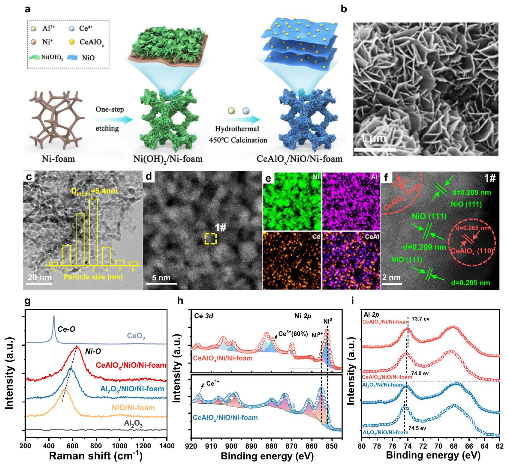
The morphology and microstructure of -foam are further observed using electron microscopic methods. The scanning electron microscopy (SEM) images of -foam preserves monolith geometry and rich 3 -dimensional cross-connected pore structure after the modification and thermal treatments (Supplementary Fig. 3). Th composite displays a honeycomb-like nanoflake appearance on the skeleton of Ni foam with an average thickness of (Fig. 1b and Supplementary Fig. 3). The adherence of on Ni foam is sufficiently strong to bare the vigorous ultrasonic treatment (Supplementary Fig. 5), which highlights the effectiveness of the NiO overlayer in anchoring the fine oxide species. Transmission electron microscopy (TEM) images of sample scraped from the structured catalysts suggest that NiO nanoparticles (distribution centered at ) are deposited on the exterior surface of Ni-foam (Fig. 1c and Supplementary Fig. 4). High angle dark field scanning transmission electron microscopy (HAADFSTEM) and energy-dispersive X-ray (EDS) element mapping images further confirm the uniform dispersion of Ce and Al over NiO particles in the nano-composite (Fig. 1d, e). Atomic-level image of region from Fig. 1d shows the lattice fringes of 0.265 nm (correspond to , Supplementary Fig. 6), demonstrating the formation of mixed oxide and loaded on the NiO support (Fig. 1f). After reduction, an inverse interface composed with oxide particles on Ni support will be formed. Raman spectroscopy is performed to investigate the metal-O vibration of different Ni-foam structured catalyst (Fig. 1g). The peak at is confirmed to the contribution of based on the comparison of passivated foam and reduced -foam catalyst, as the vibration peak disappears completely (Supplementary Fig. 7) due to the fully reduction of NiO to metallic . The redshift of vibration peaks in the -foam ( ) compares to that of -foam ( ), which is probably the effect of the formation of Al-O-Ni coordination. Then, a larger red shift of vibration appears when Ce is introduced to the -foam inverse catalyst, and no Ce O vibration is emerged, suggesting the formation of mixed oxide which affects the vibration .
The chemical state of the catalyst surface is further explored by in situ X-ray photoelectron spectroscopy (XPS, peak fitting results in Supplementary Fig. 8 and Supplementary Table 2). From Ni XPS spectra (Fig. 1h), it is confirmed that the surface of calcined -foam mainly corresponds to species ( ), which converts into metallic after reduction . The (Fig. 1h) spectra show that over surface Ce atoms become to species after reduction, which could introduce abundant oxygen vacancies in the inverse composite. Meanwhile, the 0.8 eV negative shift of the XPS peak of the -foam sample compared with Ni-foam sample demonstrates the formation of mixed metal oxides in the catalyst (Fig. 1i) . The ratio of -foam catalyst reaches (based on the region XPS spectra in Supplementary Fig. 6), which is in good agreement with the mixed metal oxides contains higher density of oxygen vacancies based on -pulse chemisorption results (Supplementary Fig. 9).
Catalytic performance of the structured catalysts
The catalytic performances of the structured catalysts for synthesis from hydrogenation are evaluated between using a gas feed of under atmospheric pressure and a gas hourly space velocity (GHSV) of . The activities of
Fig. 1 | Catalyst preparation strategy and structure characterization.
a Schematic diagram of the synthesis of -foam catalyst; SEM image of -foam catalyst; c TEM image of catalyst scraped from the Ni-foam substrate (inset is the particle size distribution histogram); d Aberration-corrected HAADF-STEM image of scraped catalyst; e EDS elemental maps of scraped catalyst, showing the distribution of
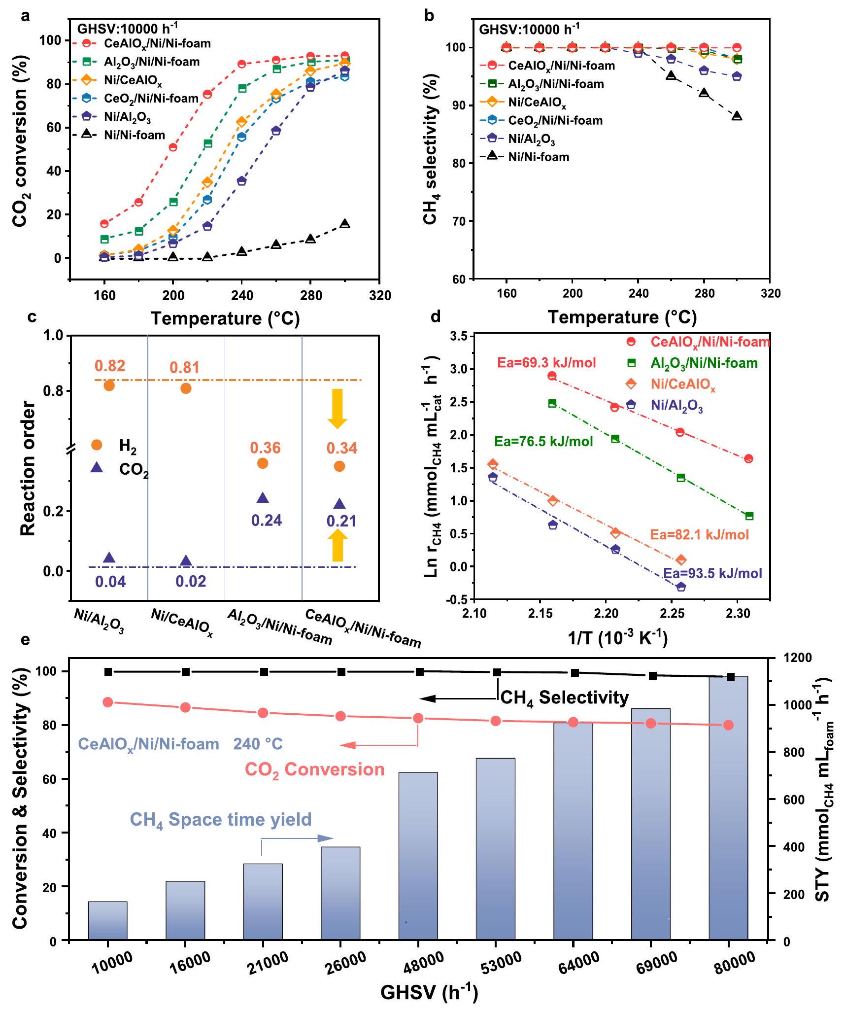
and Al; High-resolution HAADF-STEM image of the # area in d; Raman spectra of the NiO/Ni-foam, -foam, -foam, and catalysts; In situ XPS of and of -foam and foam catalysts; In situ XPS of of -foam, -foam, -foam and -foam catalysts. -foam ( , and Mg ) catalysts and the foam catalyst in methanation reaction are showed in Fig. 2a, b and Supplementary Fig. 10. Almost no conversion is observed over the -foam and Ni-foam substrates (below ). In comparison, conversion are obtained at on the -foam catalysts, suggesting the importance of oxide modification in promoting the methanation activity. Furthermore, it is found the formation of mixed oxide phase ( -foam catalyst) doubles the conversion at compared with foam (Fig. 2a, b and Supplementary Fig. 11) and is determined as the optimal composition. In the performance evaluation, -foam catalyst achieves conversion and selectivity of at , which far exceeds the conventional oxide-supported Ni catalysts. The space-time yields (STY) of of -Foam and corresponding catalyst in kinetic
region ( conversion , Supplementary Fig. 12 and Supplementary Table 4) show that the of -foam catalyst is , which is 15 times higher than that of catalyst.
For the comparison of and reaction order, diluting reaction gas was applied to ensure that is converted in the kinetic region and the effect of hotspots is eliminated. Kinetic analysis of the methanation catalysts shows the apparent and reaction orders of -foam are 0.34 and 0.21 , and those of -foam are 0.36 and 0.24 . In comparison, the reaction orders of conventional and are 0.81/0.02 and 0.82/0.04 (Fig. 2c and Supplementary Table 5). The change of the apparent kinetic orders of and suggests that the coverage decreases and surface coverage is intensified over the ensembles of -foam and -foam according
Fig. 2 | The catalytic performance of -foam catalyst. Temperaturedependent conversion and selectivity of the -foam, -foam, -foam, , and -foam catalysts (reaction conditions: GHSV ); c Reaction
orders with respect to and for methane formation; based apparent activation energy of -foam, -foam, and catalysts; e GHSV-dependent activities of -foam catalyst at .
to the Langmuir-Hinshelwood mechanism, which could significantly promote the surface reaction. By varying the GHSV for different catalysts, it is ensured that all the conversion used to calculate are below (Supplementary Fig. 13). The base of
Ni-foam is determined as , lower than -foam and much lower than that of conventional and , confirming the immense contribution of inverse structure on promotion of reaction
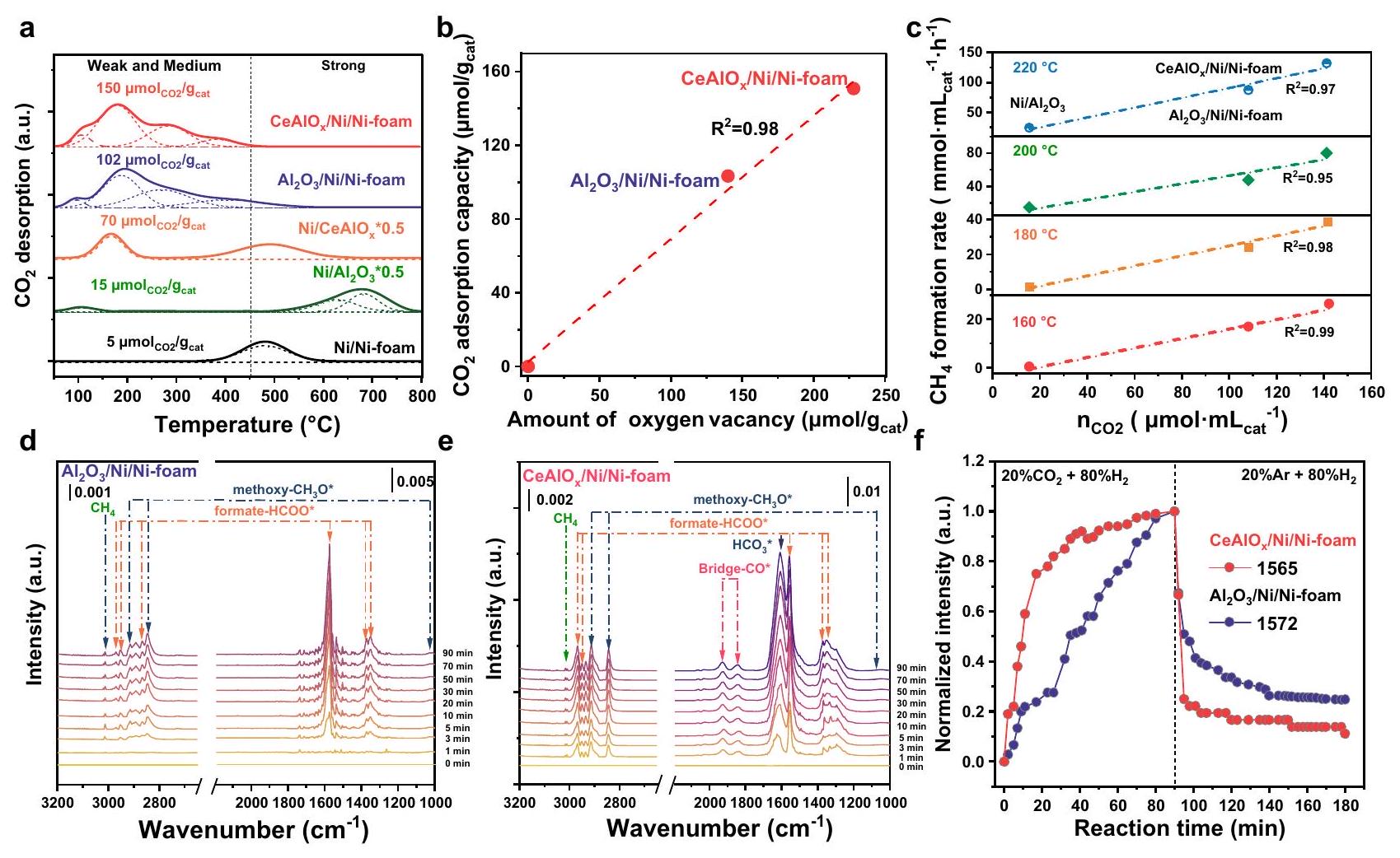
Fig. 3 | Investigation on the reaction mechanism of -foam catalyst. a The -TPD profiles of Ni-base catalysts; relationship between capture capacity and amount of oxygen vacancies on -foam and foam catalysts; the correlation of the STY methanol and the amount of adsorbed at ; d, e DRIFTs results of t the -foam catalyst and -foam catalyst in the stream of mixture under 0.1 MPa respectively at ; normalized intensities of the typical formate surface species as a function of reaction time ( for -foam; for -foam).
kinetics in methane synthesis from hydrogenation reaction (Fig. 2d).
The STY of as a function of GHSV at is further evaluated (Fig. 2e), and it is found that the conversion of foam remains above when the GHSV increases to . The corresponding STY of methane reaches ( with respect to the mass of ensemble), which is more competitive than the state-of-the-art supported Ru and Ni catalysts for the low-temperature methanation (Supplementary Table 6).
To understand the excellent catalytic performance of the -foam structured catalyst, a number of characterizations are performed to identify the active sites. temperature program desorption profiles (Fig. 3a) show the amount of adsorbed at weak and medium alkaline sites are 150 and (Supplementary Table 3). It can be seen that the capacity of weak- and mediumadsorbed display a near linear correlation with the density of oxygen vacancies ( ) (Fig. 3b). As the weak- and mediumadsorbed are determined to show a linear relationship with the intrinsic productivity of at , and (Fig. 3c), it can be confirmed that the oxygen vacancies at the inverse oxide-metal interface are probably the sites for activation at low temperature, which accounts for the activity of methanation.
In situ diffuse reflectance Fourier transform infrared spectroscopy (DRIFTs) studies further elucidate that the structure of the -foam composites affect the types and conversion rate of surface intermediates (Fig. 3d, e and Supplementary Fig. 14). Under the reaction atmosphere ( ), bridged and , formate (2970, 1563, ) and methoxy (2845, ) species are observed on -foam catalyst . In contrast, only
formate and methoxy species are observed on -foam catalyst (Fig. 3d). In addition, when is removed from the feed after steady state is reached, and formate species on the foam catalyst are rapidly consumed together with the formation of methane, and the consumption of formate species and formation of methane is also observed on the -foam (Fig. 3d and Supplementary Fig. 14), which indicates that both formate and are important intermediates on the -foam catalyst, while methanation on the catalyst mainly follows the formate pathway. Therefore, these two possible reaction pathways synergistically promote the lower temperature methanation on the Ni-foam catalyst.
Mechanism studies
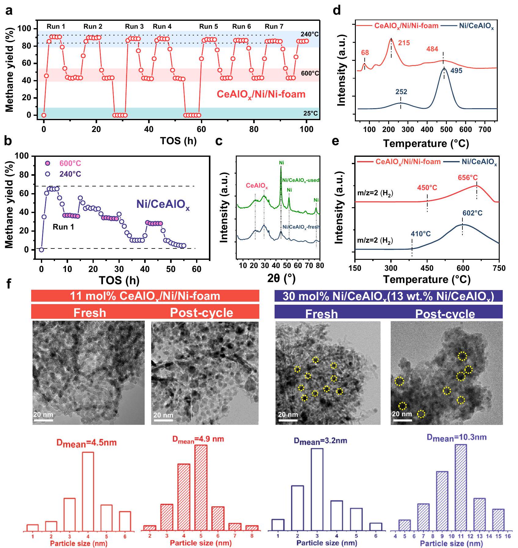
The reaction stability is probably one of the most important indicators for a practical catalyst, especially for the methanation catalyst, which faces significant challenges of sintering and carbon deposition . To investigate the thermal shock resistance of -foam structure catalyst, a seven-cycle reciprocating heating-cooling test between 25 and was performed (Fig. 4a). After each cycle, the conversion and selectivity of -foam at can be restored (Fig. 4a). In contrast, the conventional shows a rapid deactivation after only one heating-cooling cycle (Fig. 4b), which is probably due to the agglomeration of Ni NPs (see XRD patterns of the fresh and spent catalysts in Fig. 4c). This phenomenon implies that the interaction between the oxide and Ni substrate effectively inhibit the migration of Ni species and thereby prevent the undesirable sintering . Additionally, the temperature program oxidation (TPO) experiment of the spent Ni-foam and catalysts also confirms coke formed on
Fig. 4 | Thermal shock resistance of -foam catalyst. yield of a -foam and catalysts during heating-cooling treatment (reaction conditions: GHSV ); c XRD spectra of catalyst before and after cyclic reaction; d TPO results of
-foam after seven cycles is mainly amorphous carbon which can be oxidized around . While large amount of partial crystalized carbon is generated on after three cycles (mainly oxidized at ), demonstrating -foam structured catalyst is able to inhibit the formation of coke in methanation reaction (Fig. 4d). The coking resistance mechanism of the Ni -foam can be illustrated by the temperature program surface reaction experiment (Fig. 4e), which indicates the decomposition of to and carbon on the -foam is about higher than the conventional catalyst. Moreover, the size of the
scraped inverse species before and after cycling experiments maintains a fine dispersion without agglomeration ( 4.5 nm to 4.9 nm ) (Fig. 4f). On the contrary, the Ni NPs over Ni/CeAlO sinters from 3.2 nm to 10.3 nm after four heating-cooling cycle, which explains the reason for the deactivation of conventional Ni/oxide catalysts.
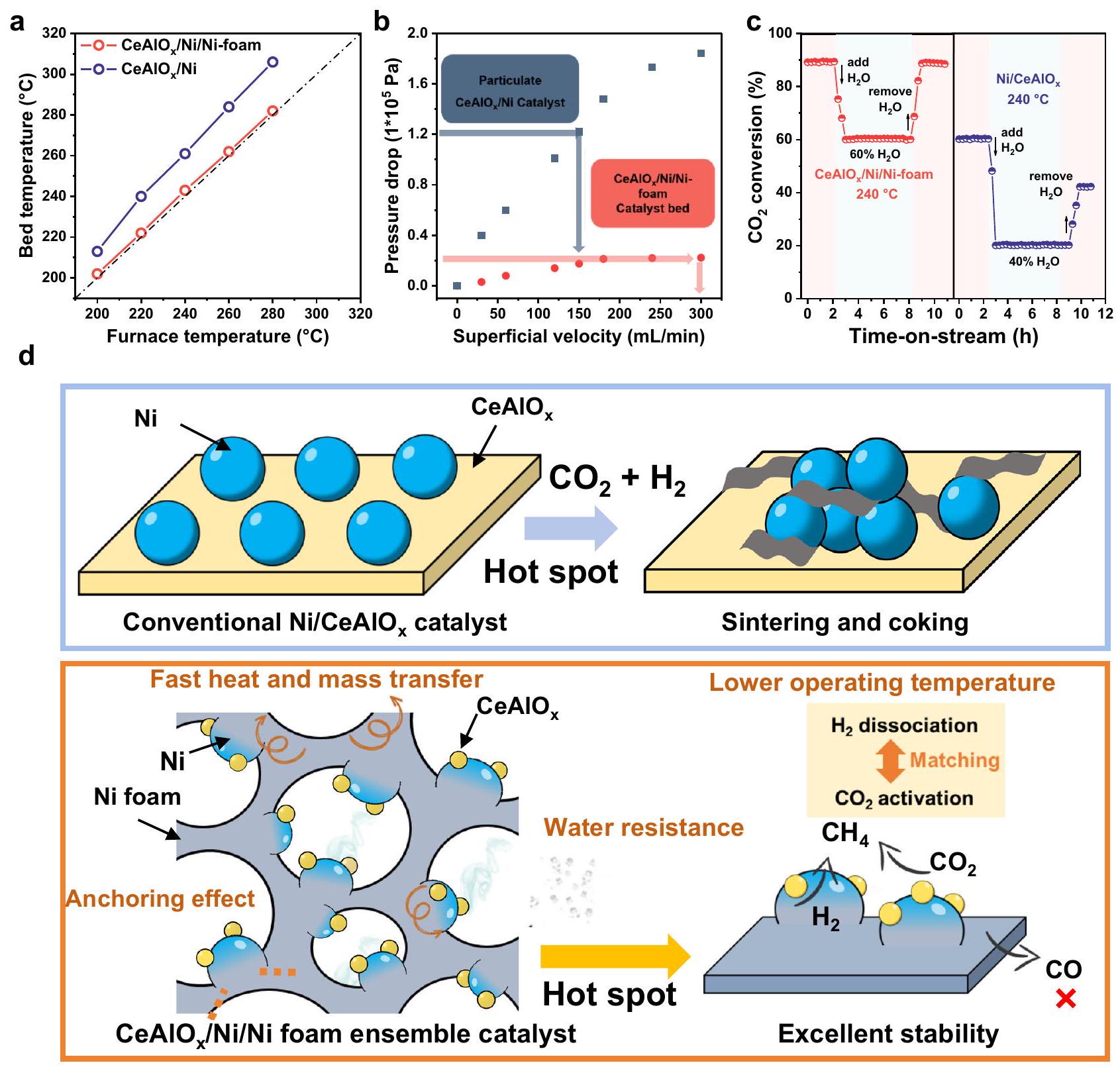
The excellent thermal stability of structural catalysts compared with the conventional supported catalyst is also probably due to the improved heat and mass transport efficiency. The temperature rise of the catalyst bed is limited below in a wide range of reaction temperature and conversion on the -foam,
Fig. 5 | Investigation of the thermal stability of structural catalyst. a The comparison of temperature-rising for the Ni -foam-structured catalyst and catalyst; pressure drop against gas superficial velocity, -foam ( 100 PPI ), ( meshes); water resistance test of -foam catalyst (reaction conditions: , ); schematic representation of a Ni-foam skeleton constrained stabilized inverse nickel catalyst and a reference sample.
in contrast, without the Ni foam support, the temperature rise of powder catalyst bed is above (Fig. 5a), indicating the diminish of the localized hotspots can be highly due to the construction of structured catalysts. The pressure drops comparison of the -foam structure catalyst and powder catalyst suggest that the pressure drop of the structured catalyst is only of the powder catalysts ( at the superficial velocity of min , Fig. 5b). This enhancaced mass transfer efficiency probably also contributes to the hotspot elimination of the nickel foam-based catalyst. Additionally, since steam is one of the main products during methanation reaction, an additional amount of steam is introduced ( ) at to investigate the water resistent property (Fig. 5c). Ni-structured catalyst loses of its under the reaction condition of , but the catalytic activity can be totally recovered after the removal of steam . In contrast, the activity of powder catalyst is lost more than , and only catalytic activity
can be recovered after removing steam. The much better water resistence of -foam structure catalyst can also be attributed to the porous structure that accelerates the diffusion of steam in the reaction.
Based on the performance and cylic stability tests for hydrogenation to methane, the structured catalyst with Ni foam skeleton and well-designed inverse species as active sites is demonstrated to display superior activity, stability and strong adaptability to unsteady operation condition and condensation compared with conventional oxide supported Ni-based catalysts (Fig. 5d). The high thermal conductivity of metal framework and the rich diffusion channels in the structured support successfully eliminate the local hotspots and prevent the accumulation of water surrounding the active sites, which benefits the thermal stability, coke elimination and water resistance. The inverse species which reduces the coverage and accelerates the reduction of and intermediates,
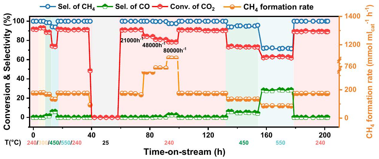
Fig. 6 | Resistance to fluctuating conditions of -foam catalysts. Long-term stability test on foam catalyst. Reaction conditions: , GHSV .
not only enhances the activity but also reduces the coke formation due to the successful suppress of decomposition side reactions. Meanwhile, the finely dispersed metal oxide species on inverse composites also enhances the anti-sintering ability of -foam catalyst and enhances the structure robustness of active species.
As methanation is a potential reaction to integrate with unstable and discontinuous hydrogen production from renewable energy, the catalyst developed for the process need to be adaptive to unsteady operation condition and potential steam condensation . Therefore, an unsteady operation condition with waving temperature and space velocity is set to simulate application scenarios and evaluate the stability of -foam structured catalyst (Fig. 6). No sign of deactivation of catalyst is observed after 200 h time on stream, suggesting the application perspective of -foam structured catalyst in hydrogen to gas processes.
Discussion
In summary, a highly active, selective and thermally stable structured catalyst with inverse ensemble active sites loaded on Ni foam is successfully prepared and applied for the hydrogenation to methane reaction. We demonstrate that the formation of mixed oxide on Ni enhances the oxygen vacancies for activation and simultaneously modulates the surface coverage of and hydrogen, which not only promotes the methanation activity by 14 times but also suppresses the decomposition of . Powered with the remarkable heat and mass transport efficiency of 3D Ni-foam and the excellent anchoring effect of overlayer prepared by the ureaetching method, the local hotspots are eliminated, and the structure of inverse ensemble is demonstrated to be intact after long-term unsteady operation or treated with steam-rich atmosphere, which overcomes the inherent stability challenges existed in the conventional supported-based catalysts. The development of the Ni-foam structured catalyst provides rational strategy to construct highly stable and affordable practical catalysts for methanation reaction.
Methods
Materials
Analytical grade chemicals including the sodium carbonate ( , purity), sodium hydroxide ( purity), nickelous nitrate hexahydrate purity), cerium nitrate hexahydrate purity) and aluminum nitrate nonahydrate purity) was purchased from Sinopharm Chemical Reagent Co., Ltd. The Ni-foam felt was purchased from Suzhou Taili Material Co. All chemicals were used as received without any further purification.
Catalyst synthesis
Preparation of -foam catalyst. The foam substrate is prepared first. In a typical synthesis procedure, circular Ni foam thin slices ( 1 g , diameter 6 mm , thickness 1.0 mm , porosity 110 PPI) are cut from Ni foam plates and sonicated in acetone for 20 min to remove surface residual organic impurities. These circular slices are then immersed in a 0.1 M HCl solution at room temperature for an additional 20 min of sonication to remove the surface nickel oxide from the Ni foam, followed by thorough rinsing with deionized water. The cleaned Ni foam thin slices ( 0.4 g ) are transferred to a stainlesssteel autoclave lined with a 50 mL polytetrafluoroethylene (PTFE) container, which contains a 35 mL solution of urea ( 6.3 mmol ). After hydrothermal treatment at for 8 h , the Ni foam coated with deep green crystals is rinsed with deionized water and dried under vacuum at for 12 h . A solution containing ( 0.875 mmol ), , and urea ( 6.5 mmol ) is prepared ( 35 mL ), and then the obtained solution is stirred for about 60 min . Subsequently, the resulting solution and foam thin slices ( 0.4 g ) are transferred to a Teflon-lined autoclave reactor ( 100 mL ), subjected to hydrothermal treatment at for 12 h . After cooling to room temperature, the sample is washed with ethanol and deionized water, dried under vacuum at for 12 h , and finally calcined at for 3 h to obtain the foam catalyst.
Preparation of catalyst. The catalyst is prepared by a coprecipitation method. Briefly, a solution containing and is prepared , and then the aqueous metal precursor solutions are added dropwise to a precipitating solution of and NaOH at vigorous stirring conditions. The resulting solution is stirred for 1 h , then maintain the pH to 10 by adding 3 M NaOH solution. After that, the precipitated mixture is aged at in the reactor for 18 h to promote the crystallization of metals. Finally, the solid precipitate is filtered out be washed with ultrapure water many times to reduce the pH of the mixture to neutral. The obtained solid is dried at overnight, and further calcinated at in .
Catalytic evaluation
The performance evaluation of hydrogenation to methane is performed in an atmospheric fixed-bed reactor. The prepared catalyst sheets ( 0.15 g , diameter 6 mm ) are loaded into a quartz tube (inner diameter and length ) and put into the reactor. The catalyst is preprocessed in at for 3 h , cooled to the reaction temperature , then the reaction gas ( ) is fed into the reactor. The actual temperature of the catalyst bed is measured using a thermocouple located at the
middle of the catalyst bed. Gas-phase products are analyzed using a gas chromatograph (GC-8860, Agilent) equipped with a thermal conductivity detector, Porapak Q and 5 A molecular sieve columns. The definitions of conversion, selectivity, carbon balance, and STY are given by the following equations:
where denotes the gas flow into the reactor, C denotes the concentration, denotes the gas chromatographic peak area, denotes the volume of catalyst and denotes the amount of substance.
The Arrhenius plots were created at a high GHSV of to ensure that the concentration of carbon dioxide produced remained below . This was achieved due to the insignificant influence of heat and mass transfer in this region. Additionally, differential mass-normalized reaction rates were calculated in the kinetic regime.
Catalyst characterization
Inductively coupled plasma-optical emission spectrometer. The ICP-OES results are performed on Varian ICP-OES 720. Sample preparation: A certain number of samples are weighed into a PTFE container, added with 5 mL concentrated nitric acid, and , sealed in a microwave digestion furnace, heated at 1200 W for 20 min to , kept for 5 min , heated for 20 min to , kept for 40 min , and cooled to room temperature. Test: The cooled solution is transferred to a 25 mL plastic volumetric bottle, and filled with deionized water. The dissolved solution is tested sequentially, and the diluted solution beyond the curve is tested again. Standard test solution: the standard solution is a national standard material, and the curve concentration points are , respectively.
X-ray diffraction. XRD is used to determine the phase composition and estimate the particle size of the catalyst. The testing is conducted using a excitation source with a scanning range of , a scanning speed of , and a step size of 0.0167 . The phase analysis is conducted by referring to the standard powder diffraction cards. The particle size of Ni is calculated using the Scherrer equation.
Surface area measurement. physical adsorption testing is conducted on the BSD-PS2 instrument. Prior to the testing, the sample is subjected to a vacuum degassing at for 4 h , followed by adsorption-desorption testing under liquid nitrogen cooling ( ) conditions. The determination of the specific surface area and distribution of pore sizes is accomplished through utilization of the Brunauer-Emmett-Teller (BET) method for calculation, in conjunction with analysis of the desorption curve using the Barrett-Joyner-Halenda (BJH) technique. temperature-programmed reduction ( -TPR). -TPR is conducted on the BELCAT-B instrument. A sample of 50 mg is weighed and pretreated in a flowing pure He gas ( ) for 1 h at . After the sample is cooled to room temperature., a flow of gas is introduced. The temperature is then ramped from to with a heating rate of for the temperatureprogrammed reduction process. The consumption of hydrogen is recorded by a thermal conductivity detector. temperature-programmed desorption ( -TPD). -TPD is conducted on the Microtrac BEL Cat II instrument. The catalyst ( 50 mg ) is pretreated at for 180 min in (heating rate of ), followed by cooling to and purge with He for 30 min . Then, the catalyst is treated in for 60 min , followed by a purge with He to remove unabsorbed and physically adsorbed . After the baseline has been stabilized, the temperature is gradually increased from room temperature to at a heating rate of in order to facilitate the desorption of .
Temperature-programmed oxidation (TPO) of spent catalysts. The catalysts, after stability test are exposed to at ambient temperature purge for 30 min , the fixed-bed reactor is heated to with a rate of and then held for 10 min . The CO and are quantified by mass spectrum analyzer (DECRA), but is the major product .
Scanning electronic microscopy. The samples were analyzed using a high-resolution field emission scanning electron microscope (FE-SEM, HITACHI Regulus 8100) operating at an acceleration voltage of 20 kV . Following that, the distribution of elements was determined utilizing EDX (Oxford Ultim Max 65).
Transmission electron microscope. TEM is conducted using a FEGTEM instrument (Tecnai G2 F30 S-Twin) operating at 300 kV . The samples are sparsely dispersed in ethanol and subsequently deposited onto copper grids coated with amorphous carbon films, followed by desiccation for TEM observations .
Scanning transmission electron microscope. The Thermo Scientific Spectra 300 Double-Corrected Transmission Electron Microscope, equipped with a Gatan Imaging Filter, was utilized to conduct the STEM and EDX experiments. The point of scanning for elemental mapping within STEM-EDX was determined at . The predetermined operating parameters necessitated the application of an acceleration voltage of 300 kV . To facilitate analysis and evaluation of the findings, the surface active phase from the reduced passivated nickel foam catalyst was extracted prior to TEM sample preparation for characterization.
X-ray photoelectron spectroscopy. X-ray Photoelectron Spectroscopy analysis is performed on a ThermoFischer ESCALAB 250 Xi equipped with an in situ reactor. The specific parameters are as follows: excitation source using Al Kalpha radiation ( ); analysis chamber vacuum level of ; working voltage of 12.5 kV ; filament current of 16 mA ; and signal accumulation for cycles. The Passing Energy is set to 30 eV with a step size of 0.1 eV . The specific operational procedure is as follows: the catalyst sample, in the form of a disc, is placed inside the reactor chamber. It is pretreated for 1 h at a set temperature in an atmosphere ( ) with a flow rate of . After cooling to room temperature, the sample is transferred to the measurement chamber without exposure to air. The measurement chamber is evacuated to a vacuum level below before conducting the analysis. Charging correction of the binding energy is performed using as a reference.
Raman spectroscopy analysis. Raman spectra are obtained using the Renishaw In Via Reflex spectrometer with a 532 nm laser excitation source. The scanning range is set from 200 to with an accuracy of . The scan test is considered complete when
consistent results are obtained from at least three positions on each sample.
Oxygen pulse titration ( -PT). For the pulse experiments of Ni-foam, -foam and -foam catalysts are pretreated at for 3 h under flow ( ), purged 10 min with He and heated to . Then the pulse experiments are repeated until the TCD peak intensity is equal.
where SF represents the stoichiometry factor, is the consumption of (deduct the -foam consumption), is the oxide mass fraction (%), and is the mass of the catalyst ( g ).
Temperature-programmed surface reaction-mass spectrum. The test procedure for dissociation: 100 mg of sample, pretreat it at for 3 h under Ar purge. Then cool down to room temperature (approximately ), and switch the to to record mass baseline. After the baseline is stable, the temperature is increased to with a heating rate of , while the mass spectrum is recorded at the same time .
In situ diffuse reflectance infrared flourier transform spectroscopy. In situ DRIFTs measurements are performed by using an FTIR spectrometer (Bruker Vertex 80) equipped with a Harrick cell and a liquid nitrogen-cooled MCT detector, along with an RGA detector for the outlet gas analysis. The -foam and -foam catalysts are reduced in gas flow at for 3 h , and then cooled down to and purged with Ar for 30 min . The temperature of in situ DRIFTs is chosen to be instead of , in order to better observe the intermediate species at low activity. 1 min is averaged for each spectrum, which is recorded at a resolution of . Prior to each experiment, background is collected at Ar and . Subsequently, the gas flow is changed to at the same temperature, and the spectra are collected simultaneously. The transmittance is obtained by dividing the collected sample reflectance spectrum by the background spectrum, then spectrum is converted to Kubelka-Monk. After 90 min reaction in an atmosphere, the inlet is switched to at the same temperature. At the same time, DRIFTs spectra are recorded to monitor the change of intensity of different surface species for another 90 min .
Data availability
The data that support the plots within this paper and another finding of this study are available from the corresponding author upon reasonable request. Source data are provided as a Source Data file. Source data are provided in this paper.
References
Yan, X. et al. Nickel@Siloxene catalytic nanosheets for highperformance methanation. Nat. Commun. 10, 2608 (2019).
Vogt, C. et al. The renaissance of the Sabatier reaction and its applications on earth and in space. Nat. Catal. 2, 188-197 (2019).
Hu, F. et al. Structure-activity relationship of Ni-based catalysts toward methanation: recent advances and future perspectives. Energy Fuels 36, 156-169 (2022).
Sterk, E. B. et al. Structure sensitivity of conversion over nickel metal nanoparticles explained by micro-kinetics simulations. JACS Au 2, 2714-2730 (2022).
Wulf, C. et al. Review of power-to-X demonstration projects in Europe. Front. Energy Res. 8, 27637-27655 (2020).
Hussain, I. et al. Recent advances in catalytic systems for conversion to substitute natural gas (SNG): perspective and challenges. J. Energy Chem. 62, 377-407 (2021).
Yang, C. et al. Intrinsic mechanism for carbon dioxide methanation over Ru-based nanocatalysts. ACS Catal. 17, 11556-11565 (2023).
Ganesh, I. Conversion of carbon dioxide into methanol – a potential liquid fuel: fundamental challenges and opportunities (a review). Renew. Sustain. Energy Rev. 31, 221-257 (2014).
Frey, M. et al. Optimization of structured cellular foam-based catalysts for low-temperature carbon dioxide methanation in a platelet milli-reactor. C. R. Chim. 18, 283-292 (2015).
Huynh, H. L. et al. Bed packing configuration and hot-spot utilization for low-temperature methanation on monolithic reactor. Chem. Eng. J. 428, 131106 (2022).
Wedel, S. et al. Steady-state multiplicity features of an adiabatic fixed-bed reactor with Langmuir-Hinshelwood kinetics; carbon monoxide or carbon dioxide methanation. Ind. Eng. Chem. Fundam. 23, 280-288 (1984).
Su, X. et al. Catalytic carbon dioxide hydrogenation to methane: a review of recent studies. J. Energy Chem. 25, 553-565 (2016).
Mustafa, A. et al. Current technology development for utilization into solar fuels and chemicals: a review. J. Energy Chem. 49, 96-123 (2020).
Nguyen, N.-P. et al. Fabrication of the coke-resistant and easily reducible catalyst for methanation. J. Energy Inst. 110, 101332 (2023).
Unwiset, P. et al. Catalytic activities of titania-supported nickel for carbon-dioxide methanation. Chem. Eng. Sci. 228, 115955 (2020).
Zhang, Q. et al. Low-temperature active, oscillation-free PdNi(al-loy)/Ni-foam catalyst with enhanced heat transfer for coalbed methane deoxygenation via catalytic combustion. Appl. Catal. B 187, 238-248 (2016).
Zhu, J. et al. Nanoporous evolutionarily structured onto a Ni foam for highly selective hydrogenation of dimethyl oxalate to methyl glycolate. ACS Appl. Mater. Interfaces 11, 37635-37643 (2019).
Zhu, J. et al. Superb Ni-foam-structured nano-intermetallic InNi catalyst for hydrogenation of dimethyl oxalate to ethylene glycol. Chem. Eng. J. 426, 130857 (2021).
Shen, M. et al. Ni-foam-structured ensemble as an efficient catalyst for gas-phase acetone hydrogenation to isopropanol. ACS Appl. Mater. Interfaces 13, 28334-28347 (2021).
Ricca, A. et al. Study of the role of chemical support and structured carrier on the methanation reaction. Chem. Eng. J. 377, 120461 (2019).
Dou, L. et al. Efficient sulfur resistance of and Ce doped hierarchically structured catalysts for low-temperature methanation integrated with electric internal heating. Fuel 283, 118984 (2021).
Ma, H. et al. Graphene intercalated Ni-SiO2/GO-Ni-foam catalyst with enhanced reactivity and heat-transfer for methanation. Chem. Eng. Sci. 194, 10-21 (2019).
Gao, Y. et al. Coupling bimetallic Ni-Fe catalysts and nanosecond pulsed plasma for synergistic low-temperature methanation. Chem. Eng. J. 420, 127693 (2021).
Lu, Z. et al. Molybdenum disulfide-alumina/nickel-foam catalyst with enhanced heat transfer for syngas sulfur-resistant methanation. ChemCatChem. 10, 720-724 (2018).
Li, Y. et al. Structured Ni-CeO2-Al2O3/Ni-foam catalyst with enhanced heat transfer for substitute natural gas production by syngas methanation. ChemCatChem. 7, 1427-1431 (2015).
Wu, C. et al. Inverse as a highly efficient methanol synthesis catalyst from hydrogenation. Nat. Commun. 11, 5767 (2020).
Tian, J. et al. methanation over Ni nanoparticles inversely loaded with and : Catalytic functions of metal oxide/Ni interfaces. Appl. Catal. B 339, 123121 (2023).
Zhu, Y. et al. Copper-zirconia interfaces in UiO-66 enable selective catalytic hydrogenation of to methanol. Nat. Commun. 11, 5849 (2020).
. et al. Insights into the interfacial structure of catalysts for methanol synthesis from hydrogenation: effects of Cu supported nano-ZrO2 inverse interface. Chem. Eng. J. 470, 144006 (2023).
Yan, H. et al. Construction of stabilized bulk-nano interfaces for highly promoted inverse catalyst. Nat. Commun. 10, 3470 (2019).
. et al. Interface-hydroxyl enabling methanol steam reforming toward CO-free hydrogen production over inverse catalyst. Appl. Catal. B 334, 122839 (2023).
. et al. Cu-supported nano- as a highly active inverse catalyst for low temperature methanol synthesis from hydrogenation. Appl. Catal. B: Environ. Energy 344, 123656 (2024).
Zhu, J. et al. Superior -foam catalyst for gas-phase hydrogenation of dimethyl oxalate to ethanol. Appl. Catal. B 270, 118873 (2020).
Xue, S. et al. NiC -foam discovered as a promising hightemperature WGSR catalyst. Fuel 353, 129270 (2023).
Zheng, Y. et al. Interface-enhanced oxygen vacancies of catalysts in situ grown on monolithic Cu foam for VOC catalytic oxidation. Environ. Sci. Technol. 56, 1905-1916 (2022).
Dou, L. et al. Enhancing methanation over a metal foam structured catalyst by electric internal heating. Chem. Commun. 56, 205-208 (2020).
Dou, L. et al. Novel core-shell-like nanocomposites MgAlO-rGO through an in situ self-reduction strategy for highly efficient reduction of 4-nitrophenol. Dalton Trans. 46, 15836-15847 (2017).
Hu, F. et al. Reduced graphene oxide supported Ni-Ce catalysts for methanation: the support and ceria promotion effects. J. CO2 Util. 34, 676-687 (2019).
. et al. Catalytically efficient interface for medium temperature water-gas shift reaction. Nat. Commun. 13, 2443 (2022).
Zhang, J. et al. Exceptional low-temperature activity of a perovskitetype solid solution-supported Ni-based nanocatalyst towards methanation. Catal. Sci. Technol. 11, 3894-3904 (2021).
Zhang, S. et al. Solid frustrated-Lewis-pair catalysts constructed by regulations on surface defects of porous nanorods of . Nat. Commun. 8, 15266 (2017).
Italiano, C . et al. CO and methanation over Ni catalysts supported on and oxides. Appl. Catal. B 264, 118494 (2020).
Liu, W. et al. Insights into flower-like spheres with rich unsaturated pentacoordinate sites stabilizing Ru-CeO for propane total oxidation. Appl. Catal. B 292, 120171 (2021).
Xie, Y. et al. Frustrated Lewis pairs boosting low-temperature methanation performance over nanocatalysts. ACS Catal. 12, 10587-10602 (2022).
Lin, L. et al. In situ characterization of nanocatalysts for hydrogenation: morphological effects of nanostructured ceria on the catalytic activity. J. Phys. Chem. C. 122, 12934-12943 (2018).
Chen, Y. et al. An active and stable nickel-based catalyst with embedment structure for methanation. Appl. Catal. B 269, 118801 (2020).
Lin, L. et al. Reversing sintering effect of Ni particles on via strong metal support interaction. Nat. Commun. 12, 6978 (2021).
Zhou, J. et al. Interfacial compatibility critically controls metal-support interaction modes in hydrogenation. Nat. Commun. 13, 327 (2022).
Yang, J. et al. A hydrothermally stable irreducible oxide-modified catalyst for methane combustion. Angew. Chem. Int. Ed. 59, 18522-18526 (2020).
Wang, X.-F. et al. boosted water tolerance of Pt nanoparticle on for propane oxidation. Appl. Catal. B 338, 123000 (2023).
Wang, C. et al. Nickel catalyst stabilization via graphene encapsulation for enhanced methanation reaction. J. Catal. 334, 42-51 (2016).
Rao, T. U. et al. Selective hydrogenation of furfural to tetrahydrofurfuryl alcohol in 2-butanol over an equimolar Ni-Cu-Al catalyst prepared by the co-precipitation method. Energy Convers. Manag. 265, 115736 (2022).
Liu, Y. et al. Embedding high loading and uniform Ni nanoparticles into silicalite-1 zeolite for dry reforming of methane. Appl. Catal., B 307, 121202 (2022).
Wang, K. et al. Kinetically controlled, scalable synthesis of nanosheet arrays on nickel foam toward efficient oxygen evolution: the key role of in-situ-generated -NiOOH. Adv. Mater. 33, 2005587 (2021).
Li, H. et al. Ultra-durable catalysts for dry reforming of methane enabled by dynamic balance between carbon deposition and elimination. Chem. Catal. 2, 1748-1763 (2022).
Acknowledgements
This work is financially supported by the Zhejiang Provincial Natural Science Foundation of China (LR22B030003, LR21B030001 and LQ24B030016), Natural Science Foundation of China (22278367 and 22178302), National Key R&D Program of China (2022YFB4003100), China Postdoctoral Science Foundation Grant (2022M712817), Beijing National Laboratory for Molecular Sciences (BNLMS202011) and Research Fund of Department of Education of Zhejiang Province (Y2O2249632). We acknowledge the Electron Microscopy Center of Zhejiang University of Technology for the AC-TEM test.
Author contributions
L.L., X.L., and S.Y. designed the study. X.T. performed most of the reactions. X.T. and Q.S. did the most data analysis. W.L., X.H., and H.-F.L. carried out the stability test. H.-B.L. carried out the DRIFTs analysis. Q.C. did STEM characterization. L.L., S.Y., Q.S., and X.T. wrote the paper. All authors performed certain experiments and discussed and revised the paper.
Competing interests
The authors declare no competing interests.
Additional information
Supplementary information The online version contains
supplementary material available at https://doi.org/10.1038/s41467-024-47403-4.
Correspondence and requests for materials should be addressed to Siyu Yao or Lili Lin.
Peer review information Nature Communications thanks Yong Lu and the other, anonymous, reviewers for their contribution to the peer review of this work. A peer review file is available.
Reprints and permissions information is available at
Institute of Industrial Catalysis, State Key Laboratory of Green Chemistry Synthesis Technology, College of Chemical Engineering, Zhejiang University of Technology, Hangzhou, Zhejiang 310014, China. Zhejiang Carbon Neutral Innovation Institute & Zhejiang International Cooperation Base for Science and Technology on Carbon Emission Reduction and Monitoring, Zhejiang University of Technology, Hangzhou 310014, China. Key Laboratory of Biomass Chemical Engineering of Ministry of Education, College of Chemical and Biological Engineering, Zhejiang University Hangzhou 310027, China. These authors contributed equally: Xin Tang, Chuqiao Song. e-mail: yaosiyu@zju.edu.cn; linll@zjut.edu.cn