رقائق ميكروية من Fe3C ذات أنيسوتروبية عالية تم إنشاؤها من خلال تحول الطور في الحالة الصلبة لامتصاص الميكروويف بكفاءة Highly anisotropic Fe3C microflakes constructed by solid-state phase transformation for efficient microwave absorption

المجلة: Nature Communications، المجلد: 15، العدد: 1
DOI: https://doi.org/10.1038/s41467-024-45815-w
PMID: https://pubmed.ncbi.nlm.nih.gov/38374257
تاريخ النشر: 2024-02-19

رقائق ميكروية من Fe3C ذات أنيسوتروبية عالية تم إنشاؤها من خلال تحول الطور في الحالة الصلبة لامتصاص الميكروويف بكفاءة

تاريخ الاستلام: 14 مارس 2023
تم القبول: 30 يناير 2024
نُشر على الإنترنت: 19 فبراير 2024

تحقق من التحديثات

رونغتشي تشاو © تونغ قاو يكسينغ لي (ب) تشو سون تشنغيو زانغ ليانزي جي، تشينغلونغ هو، شياوليان ليو، زينهوا تشانغ، شيوفينغ تشانغ © غاوو كين (1)

الملخص

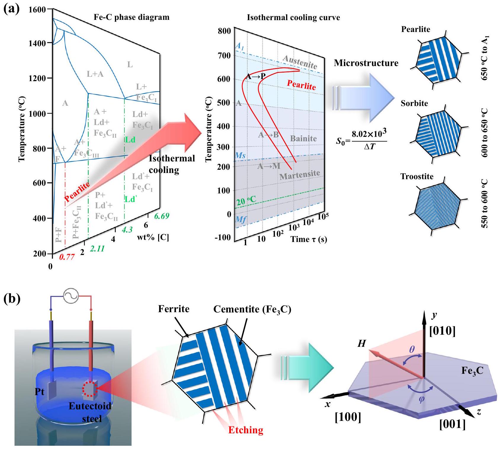
يمكن أن توفر المواد المغناطيسية اللينة ذات الهندسة الرقيقة أنيسوتروبية الشكل لكسر حد سنوك، مما يعد واعدًا لتحقيق رنينات فيرومغناطيسية عالية التردد وخصائص امتصاص الميكروويف. هنا، ثنائية الأبعاد (2D) تُحصل على الرقائق الدقيقة ذات التوجه البلوري من خلال تحويل الطور في الحالة الصلبة المدعوم بإزالة السبائك كهربائياً. يمكن تنظيم التباين في الشكل بشكل أكبر من خلال التحكم في سمك المادة ثنائية الأبعاد. الرقائق الدقيقة تحت درجات حرارة التبريد المتساوية. وبالتالي، يتم ضبط التردد الرنيني بشكل فعال من 9.47 و 11.56 جيجاهرتز تحت التبريد المتساوي من إلى يمكن أن تصل الجزء التخيلي من النفاذية المعقدة إلى 0.9 عند 11.56 جيجاهرتز، وأدنى خسارة في الانعكاس ( ) هو مع عرض نطاق امتصاص فعال ( 2.55 جيجاهرتز. توفر هذه الدراسة رؤى حول تحضير مواد فقدان مغناطيسي عالية التردد للحصول على ماصات ميكروويف عالية الأداء وتحقق تحضير مواد وظيفية من مواد هيكلية تقليدية.

لقد ظهرت التداخلات الكهرومغناطيسية (EM) كمشكلة حاسمة مع التطور السريع لتقنيات الاتصال عالية التردد والتصغير الميكروي لأجهزة المعلومات الإلكترونية، مما أثار التطور السريع لمواد امتصاص الموجات الكهرومغناطيسية. من بين جميع هذه الإنجازات، تحتل المواد المغناطيسية اللينة مكانة مهمة في تصميم المواد بسبب قدراتها الممتازة على فقدان المغناطيسية الناتجة عن التشبع المغناطيسي العالي. . ومع ذلك، يمكن أن تتعطل سلوكيات الرنين المغناطيسي الفيرومغناطيسي الخاصة بهم بسبب العلاقة المتناقضة بين قدرة الفقد والتردد، والمعروفة بحد سنوك . وبالتالي، تم إدخال مواد عازلة مثل الكربون وMXene والسيراميك لتحقيق امتصاص مرضٍ لموجات EM عند ترددات الجيجاهرتز . ومع ذلك، لا يزال هناك نقص في نهج لتجاوز حد سنوك من خلال التلاعب بالمواد الفيرومغناطيسية نفسها، مما يحد من تطوير المواد عالية…
مواد فقدان المغناطيسية الترددية وتحسين المواد المركبة.
تم التعرف على عدم التماثل في الشكل، الذي يتم إنشاؤه من خلال عمليات تحضير قابلة للتحكم، كمسار واعد لمعالجة هذه القصور. يمكن أن تؤدي هندسة الرقائق إلى تحفيز تباين فعال في المستوى في المواد المغناطيسية اللينة لكسر حد سنوك، مما قد يحسن من قدرة فقدان المغناطيسية عند ترددات الجيجاهرتز. تحت هذه الإرشادات، تشمل مواد مغناطيسية ناعمة متنوعة، مثل المواد الشبيهة بالرقائق أوراق نانوية بلورية مثل الرقائق رقائق دقيقة ورقائق الحديد الكربوني تمت دراستها، حيث تم تمديد ترددات الرنين المغناطيسي الفيرومغناطيسي لها إلى مناطق الجيجاهرتز. ومع ذلك، يجب ملاحظة أن قدرات فقدانها، التي تعكسها الجزء التخيلي من النفاذية المعقدة ( )، لا تزال تظهر ميلاً متناقصاً مع زيادة التردد إلى
منطقة التردد العالي. على سبيل المثال، قيم من ، ، و الفريت هي ، و 1.05 عند و 6.0 جيجاهرتز، على التوالي. قيم الباريوم الحديدي، و تم تقليل السيراميك إلى و 0.48 عند و لذلك، هناك حاجة ملحة لمادة مغناطيسية ناعمة ذات تردد رنين مغناطيسي حديدي عالي وقدرة على فقدان المغناطيسية لتلبية متطلبات التطبيقات عالية التردد.
سمنتيت يمكن أن يكون ( ) ذو المغنطة العالية المشبعة مرشحًا مثاليًا لتحقيق المتطلبات المذكورة أعلاه بسبب تشبعه العالي. ومع ذلك، لا يزال هناك نقص كبير في التركيب القابل للتحكم في الشكل من خلال طرق الكيمياء التقليدية بسبب هياكل من الصعب تقييدها بواسطة عوامل الطلاء. هنا، نقترح مسارًا عبر تحويل الطور في الحالة الصلبة للحصول على التحضير على نطاق واسع لـ رقائق دقيقة مع توجيه بلوري. يمكن تعديل الشكل عن طريق التحول الطوري في الحالة الصلبة، ويمكن الحصول على المادة عن طريق التحليل الكهربائي.
إزالة السبائك عند جهد ثابت (CV) قدره -0.4 فولت. تشير أداءات الاستجابة الكهرومغناطيسية والمحاكاة النظرية إلى أن تردد الرنين المغناطيسي الفيرومغناطيسي يعتمد على زيادة الفعالية في الاتجاه الأفقي الناتجة عن هندسة الرقائق، والتي يمكن تنظيمها عن طريق ضبط درجات حرارة التبريد الأيزوحرارية للفولاذات الأوكتويد. ونتيجة لذلك، فإن 2D رقائق دقيقة معالجة عند يمكن أن تحقق أعلى أنيسوتروبي، مما يمكن أن يحقق قدرة ممتازة على فقدان المغناطيسية ( 0.9 عند تردد 11.56 جيجاهرتز. وبالتالي، توضح نتائجنا العلاقة بين الأنيسوتروبي وقدرة فقدان المغناطيسية عند الترددات العالية، مقترحةً مسارًا جديدًا لتصميم مواد امتصاص الميكروويف عالية الأداء.

النتائج

وفقًا لمخطط الطور الثنائي للحديد والكربون ومنحنيات التبريد الأيزوحراري للفولاذ الإيتكتويدي ) (الشكل 1أ)، يمكن تغيير الميكروهياكل للبيرلايت من خلال عملية التبريد الإيزوحراري ضمن مناطق درجات الحرارة إلى درجة حرارة
الشكل 1 | عملية التخليق (مسار تصميم التحول الطوري في الحالة الصلبة) لـ ميكروفليكس. مخطط الطور الثنائي ومنحنى التبريد عند درجة حرارة ثابتة للفولاذ الإيوتيكتويدي ورسوم توضيحية تخطيطية للبيرلايت والسوربايت والتروستيت، والخطوط البيضاء والزرقاء تمثل الفيريت. ، على التوالي. (A: أوستينيت، B: باينيت، F: فيريت، L: سائل، Ld/Ld’: ليدبوريت، M: مارتينسيت، P: بيرليت،
تشطيب مارتنسيت، بداية المارتنسيت، : المسافة المتوسطة بين الطبقات) (ب) رسومات تخطيطية لعملية إزالة السبائك الكهروكيميائية وشكل رقائق دقيقة، و الميكروفليك (يمين) مشتق من شريط الأسمنت الأزرق (وسط) بعد عملية إزالة السبائك.
تحول النيوتيكتويد (المُشار إليه بـ متوسط المسافة بين الطبقات من هياكل الميكروستركتير المختلفة للبيرلايت، ما يُعرف بالبيرلايت ( إلى )، سوربيت ( ) ، وتروستيت ( يمكن تقييمه من خلال الصيغة التجريبية لـ يشير إلى الفرق بين درجة حرارة المعالجة الحرارية ودرجة حرارة التبريد المتساوي الحرارة) ، مما يشير إلى أنه يمكن تعديل سماكات السمنتيت من خلال تصميم درجات الحرارة الأيزوثرمية. في هذا السياق، تم قطع الفولاذ الأوكتويدي الأصلي أولاً إلى شكل مكعب بحجم وتمت معالجة الحرارة عند لمدة 3 ساعات لتحقيق الأوستنيت بالكامل. ثم، تم وضع سوائل الصلب الأوستنيتي في الملح المنصهر لتحقيق عملية التبريد الإيزوحراري، حيث تحول الأوستنيت إلى بيرلايت أو سوربايت أو تروستيت. أخيرًا، تم تعيين السوائل كقطب كهربائي وتم توصيلها بمحطة العمل الكهروكيميائية في وضع CV ( -0.4 فولت ). رقائق دقيقة، تُرمز بـ ( يمثل درجة حرارة التبريد)، تم تحضيرها عن طريق إزالة السبائك الكهروكيميائية لملمس الفريت داخل محلول من KCl و كما هو موضح في الشكل 1ب. يمكن التعرف على منحنيات التيار المقابلة لعملية إزالة السبائك الكهروكيميائية مع اتجاهات تناقص، كما هو موضح في الشكل التكميلي S1.
كما هو موضح في الشكل 2a، يمكن ملاحظة بنية بيرلايت نموذجية في جميع العينات باستخدام المجهر الإلكتروني الماسح (SEM)، حيث تمثل الخطوط الساطعة والداكنة نسيج السمنتيت والفريت، على التوالي. تم جمع وتلخيص السماكات المقابلة للسمنتيت في الشكل 2e والشكل التكميلي 2. انخفضت السماكات من 22.0 إلى 15.7 نانومتر مع انخفاض درجات حرارة التبريد من 700 إلى ، مما يوحي بأن يمكن التلاعب بالهياكل من خلال عملية التبريد الإيزوحراري. الميكروهياكل لسبائك الفولاذ الإيتكتويد بعد عملية إزالة السبيكة تمت دراسة الخصائص باستخدام المجهر الإلكتروني الماسح (SEM) كما هو موضح في الشكل التكميلي 3. يمكن ملاحظة أن الفريت قد تم حفره، وتم بناء السلف بواسطة الأسمنتيت ذو الهيكل الرقيق. بعد ذلك، تم دراسة الميكروهياكل لـ 2D تمت دراسة الميكروفليك بواسطة المجهر الإلكتروني الماسح (SEM) والمجهر الإلكتروني الناقل (TEM)، كما هو موضح في الشكل 2b وc. هنا، يمكن ملاحظة هيكل فليك غير منتظم في جميع العينات. يمكن ملاحظة أن سمك Fe 3 C هو على مقياس النانو، ولكن العرض والطول على مقياس الميكرون، مما يؤدي إلى نسبة أبعاد عالية لتعزيز عدم التماثل في الشكل لتحسين أداء الرنين الطبيعي. توزيعات العناصر والهياكل البلورية لـ تم الكشف عنها بواسطة الأشعة السينية المشتتة للطاقة
الشكل 2 | توصيفات الميكروهيكل. أ صور SEM للفولاذ الإيتكتويدي أثناء التبريد الإيزوثيرمي عند درجات حرارة مختلفة، شريط القياس: صور SEM عالية الدقة لـ ، و رقائق دقيقة، مقياس الرسم: صورة TEM عالية الدقة، خرائط EDS الذرية، وصورة SAED لـ -700 ميكروفلَيك، شريط القياس: رسم تخطيطي للبيرلايت
عملية إزالة السبائك الكهروكيميائية، واتجاهات التحليل. ملخص لسمك رقائق دقيقة (خط التركيب: ). الرقم يشير إلى درجة حرارة التبريد الأيزوحراري، وبيانات المصدر متاحة كملف بيانات المصدر.
التحليل الطيفي (EDS) وحيود الأشعة السينية (XRD)، على التوالي (الأشكال التكميلية S4 وS5). تم عرض المخطط التخطيطي للبيرلايت في الشكل 2d وتم عرض التعريف المقابل للسماكة. تم توزيع عنصرين مركبين، الكربون والحديد، بشكل موحد في الرقائق الدقيقة، وكانت هياكلها الطورية متطابقة بشكل كبير مع بطاقة الطور القياسية PDF#85-1317 ، مما يشير إلى أن الـ 2D تم الحصول على رقائق دقيقة بنجاح من خلال عملية إزالة السبائك الكهروكيميائية.
باستخدام مجهر الإلكترون النافذ المصحح للانحراف الكروي، قمنا بمزيد من التحقيق في البنى المجهرية لهذه المواد ثنائية الأبعاد. رقائق دقيقة، حيث صور TEM عالية الدقة (HR-TEM) لـ ، و تم الحصول عليها وعرضها في الشكل التكميلية 6. كما أظهر تخطيط EDS الذري، فإن ذرات الحديد والكربون موزعة بشكل موحد في الرقائق الدقيقة ثنائية الأبعاد. تكشف الصورة المكبرة لصور HR-TEM والصور المعكوسة لتحويل فورييه السريع (IFFT) (الشكل التكميلية S6B) المزيد عن هياكل الشبكة لـ حيث تمثل النقاط الحمراء ذرات الحديد والنقاط الزرقاء هي الكربون. يمكن العثور على محور المنطقة لجميع الـ هو [010]، الذي تم تحديده من خلال صور حيود الإلكترون في المنطقة المختارة (SAED) الموضحة في الأشكال التكميلية S6A و S7. يستنتج أن التركيب البلوري للثنائي الأبعاد الميكروفليك هو نظام بلوري متعامد مع مجموعة الفضاء Pnma. يمكن استنتاج الأنيسوتروبي المغناطيس البلوري، حيث يقع المحور السهل [001] في مستوى ثنائي الأبعاد. الرقائق الدقيقة والمحور السهل الثاني [010] يقع خارج المستوى وبالتالي، فإن التباين الداخلي في المستوى الذي تم تقديمه من خلال التحول الطوري في الحالة الصلبة المدعوم بإزالة السبائك الكهروكيميائية يمكن أن يحسن بشكل فعال قدرة فقدان المغناطيسية في منطقة التردد العالي.
تم تحليل الأداءات المغناطيسية لجميع العينات من خلال حلقات الهسترسيس، كما هو موضح في الأشكال التكميلية S8 و S9. كانت قيم التشبع المغناطيسي ( ) هي 97.7، 103.5، 114.6، ، و ، على التوالي، والقدرات القهرية هم ، و 69.6 أوي. الـ زاد مع زيادة السماكات لـ رقائق دقيقة، بينما أظهر ظاهرة عكسية. الـ الميكروفليكس قدمت أعلى بين جميع العينات. لأن القوة الطاردة تتناسب مع ثابت التباين. يمكن استنتاج أن زيادة القوة الطاردة هي نتيجة لزيادة الأنيسوتروبيات في الأبعاد الثنائية. الرقائق الدقيقة. وبالتالي، يمكن التحكم بكفاءة في التباين الشكلي عن طريق تعديل ظروف التبريد الإيزوحراري. .
أداء استجابة الميكروويف لجميع الـ تم قياس الرقائق الدقيقة بواسطة محلل الشبكة المتجهة (VNA) في نطاق التردد لـ كما هو موضح في الأشكال التكميلية S10 و S11. تم تكرار قياسات كل عينة أكثر من 5 مرات. بشكل عام، يجب ألا يتم ملاحظة قدرة فقدان العزل في مادة فقدان مغناطيسي واحدة. في جميع الرقائق الدقيقة، يمكن ملاحظة أن قيم السماحية المعقدة للأجزاء الحقيقية ( تقريبًا مركزة عند 20 والأجزاء التخييلية ) تتركز عند 0. ومع ذلك، يمكن ملاحظة بعض قمم الرنين في أنماط السماحية المعقدة، سواء في الأجزاء الحقيقية أو التخيلية. لتوضيح موقع هذه القمم الرنانة بوضوح، تم استخدام الشكل المتراكب للسماحية المعقدة والنفاذية المعقدة وعرضه في الشكل التوضيحي 12. يمكن ملاحظة أن القيم يمكن العثور عليها في منطقتين: نقطة التحول عالية التردد للجزء الحقيقي، وكلا طرفي قمة الرنين للجزء التخييلي. يرتبط هذا الظاهرة بشكل رئيسي بالتحول بين السماحية والنفاذية، والذي يتحقق من خلال الاتصال بين رقائق دقيقة بسبب هياكلها المجهرية عالية التباين وفقًا لدراسات مثل جزيئات النيكل النانوية المعبأة بإحكام، وأنابيب الكربون متعددة الجدران، والعناقيد دون النانوية في الأقفاص النانوية، فإن تجمع الوسط الموصل سيبني الشبكة الموصلية، مما يؤدي إلى سلوك استقطاب معزز لزيادة قدرة فقدان العزل. . لذلك، غير المنتظم
شكل ستشكل الرقائق الدقيقة شبكة موصلة في عينة اختبار EM، مما يمكن أن يحفز الاستقطاب حول الرنين الطبيعي وبالتالي يؤدي إلى اهتزاز النفاذية المعقدة.
من نتائج النفاذية المعقدة، يمكن العثور على رنات فيرومغناطيسية نموذجية في جميع العينات، وتكون تردداتها ضمن مناطق . تم ملاءمة النفاذية المعقدة لجميع العينات من خلال معادلة لاندو-ليفشيتز-غيلبرت (LLG) استنادًا إلى خمسة نتائج تجريبية مختلفة، وقد تم توضيح تفاصيل عملية الملاءمة في قسم الطريقة. هنا، تم زيادة ذروة الرنين ( يمكن ملاحظته مع انخفاض درجة الحرارة الأيزوثرمية (الشكل 3 أ، ب). يمكن ملاحظة أن من -700 ميكروفليك، الذي يحتوي على أقل أنيسوتروبي مغناطيسي من بين جميع العينات، يمكن أن يصل حتى 9.73 جيجاهرتز، وهو أعلى بكثير من تلك المواد المغناطيسية اللينة التي تم الإبلاغ عنها سابقًا مثل الأفلام الرقيقة ذات الاتجاه c-axis hcp-(Colr). و أفلام رقيقة بنمط مخطط مادي معدل (5.8 جيجاهرتز) ، و ومركباتها . تشير النتائج إلى أنه يمكن تحسين قدرات فقدان المغناطيس بشكل كبير في البعد الثاني. الرقائق الدقيقة من خلال ضبط درجة الحرارة الأيزوثرمية، المنسوبة إلى التلاعب في أنيسوتروبي الشكل. في الحالة المثلى الرقائق الدقيقة، التي تظهر أعلى نسبة لعدم التماثل، يمكن تحسينه إلى 11.56 جيجاهرتز (الشكل 3c). بالنسبة لقدرة فقدان المغناطيسية (الجزء التخيلي من النفاذية المعقدة، قيم جميع الـ وصلت الرقائق الدقيقة إلى 1.05، ، و0.90 عند ، 11.00 و 11.56 جيجاهرتز، على التوالي. قدرات فقدان المغناطيسية لـ يمكن تحسين الرقائق الدقيقة بشكل فعال في المناطق ذات التردد العالي مقارنة بـ الفريتات (0.31، ، و . علاوة على ذلك، لتوضيح قدرات فقدان المغناطيس المحسّنة بصريًا، نمط ضد من تمت مقارنة الميكروفليكس مع المواد الأخرى المبلغ عنها لفقدان المغناطيسية في الشكل 3d (المراجع التكميلية 1-26)، حيث يمكن أن تحتوي العينات ذات التباين المتزايد على أداء مرضٍ لفقدان المغناطيسية عند جيجاهرتز بين التقارير ذات الصلة. علاوة على ذلك، زوايا فقدان المغناطيسية تم حسابها بواسطة النفاذية المعقدة للإشارة إلى أداء الخسارة بشكل أكبر الرقائق الدقيقة (الشكل 3e). مشابهًا للاختراق المعقد، تم تحسين قدرات الفقد مع زيادة التباين.
خصائص امتصاص الميكروويف ثنائية الأبعاد تم تقييم الرقائق الدقيقة بواسطة نظرية خط النقل ، كما هو موضح في الشكل 3c والشكل التكميلي 13. الحد الأدنى من فقدان الانعكاس ( قيم لـ هم ، و -56.99 ديسيبل، على التوالي، حيث تشير -10 و -20 ديسيبل إلى أن و يمكن تقليل طاقة EM الواردة . لعرض نطاق الامتصاص الفعال ( )، قيم 3.75 و 2.69 جيجاهرتز مع سماكات ، ويمكن ملاحظة 1.35 مم. الـ 2D تظهر الرقائق الدقيقة أداءً ممتازًا في امتصاص الميكروويف فقط من خلال قدراتها على فقدان المغناطيسية. بالنسبة لأداء مطابقة المعاوقة لـ رقائق دقيقة، قيم تم جمعها وعرضها في الشكل التكميلية 14. عادةً، يجب اعتبار القيم في المناطق 0.8 و 1.2 كأداء ممتاز لمطابقة المقاومة. . هنا، الـ 2D يمكن أن تحقق الرقائق الدقيقة أداءً مرضيًا في المطابقة في جميع مناطق التردد )، مما يشير إلى أن التلاعب في أنيسوتروبي الشكل يمكن أن يحسن في الوقت نفسه توافق المعاوقة وأداء امتصاص الميكروويف في المناطق ذات التردد العالي.
لذلك، يُستنتج أنه يمكن تحقيق قدرة فقدان مغناطيسي عالي التردد في رقائق دقيقة ذات أنيسوتروبية شكل محسّنة. لتحديد تفاصيل هذه الأداءات بشكل أكبر، تم استخدام مجهر الإلكترون الناقل لورنتز (L-TEM)، والصور المقابلة في التركيز (الشكل 4a، b) وفوق التركيز (الشكل 4c، d) موضحة، حيث يمكن ملاحظة هياكل نطاق الشريط في الرقائق الدقيقة. يمكن أن ينتج عن نواة مجالات الشريط ظهور تباين داخلي خارج المستوى، وهو مشابه للتلاعب بالمجالات المغناطيسية في المواد التي تم ترسيبها (أو تبخيرها).
الشكل 3 | قدرات فقدان المغناطيسية. أ الجزء الحقيقي ( ) و الجزء التخيلي ) من النفاذية المعقدة في مناطق التردد ، حيث يتم تركيب الخطوط الملونة من الخطوط التجريبية (الخطوط الرمادية) من خلال معادلة لاندو-ليفشيتز-غيلبرت (LLG). ج ملخص لترددات الرنين الطبيعية (خط التركيب: الامتصاص الفعال
عرض النطاق، خسارة الانعكاس والسماكة المقابلة لـ . د مقارنة بـ ضد المواد المغناطيسية اللينة المبلغ عنها و . ا التان من رقائق دقيقة في منطقة التردد لـ تُقدم بيانات المصدر كملف بيانات مصدر.
أفلام رقيقة مغناطيسية عن طريق تعديل الأنيسوتروبي العمودي الهياكل النطاقية تحت تأثير مجال مغناطيسي ثابت يمكن إعادة بناء ( ) بواسطة محاكاة الميكرو مغناطيسية باستخدام مومكس من خلال اعتبار عدم التماثل في الشكل كعدم تماثل فعال في المستوى كما هو موضح في الشكل 4e. اللون يدل على المكون السيني للتغنطيسية. النتائج المحاكية متوافقة مع التوزيع المحسوب للتغنطيسية من صور L-TEM المتباينة بواسطة طريقة معادلة نقل الكثافة الكلاسيكية (TIE). (انظر الشكل 4f). وبالتالي، فإن سلوكيات الرنين المغناطيسي الفيرومغناطيسي لـ يمكن أيضًا الحصول على الرقائق الدقيقة تحت درجات حرارة مختلفة من المجالات المغناطيسية الساكنة عن طريق حل معادلة لاندو-ليفشيتز-غيلبرت عدديًا.
تظهر الشكل 5a طيف الرنين المغناطيسي الفيرومغناطيسي لـ الرقائق الدقيقة تحت درجات حرارة مختلفة بعد الحصول على الهياكل المغناطيسية الثابتة بقيم مختلفة من التي يتم تحفيزها بواسطة عدم تماثل الشكل لـ رقائق دقيقة بسماكات مختلفة. الترددات الرنانة للمحاكاة تزداد الميكروفليكس من 15.1 جيجاهرتز إلى 17.8 جيجاهرتز مع الزيادة في من إلى بفاصل من ، حيث القيم المختارة لـ يتم اعتبارها لتناسب التغيير في القوة الطاردة (الأشكال التكميلية S8 و S9) والتغيير في التردد يتماشى مع النتائج التجريبية. يمكن أن يكون الفرق بين قيم التردد في المحاكاة والتجربة ناتجًا عن العيب في نظام المواد الحقيقي، حيث يتم اعتبار نموذج المادة المثالي في المحاكاة الميكرو مغناطيسية. وبالتالي، يُستنتج أن الزيادة
يمكن أن تُنسب الترددات الرنانة إلى الزيادة في التباين الفعال في المستوى الناتج عن أشكال الرقائق، والتي يمكن التحكم فيها من خلال ضبط درجات حرارة التبريد الأيزوحراري. علاوة على ذلك، فإن توزيع السعة للرنين عند 15.1 جيجاهرتز لـ -700 ميكروفليك هو موضح في الشكل 5ب، ج، الذي يركز على موقع جدران المجال ويسمى أوضاع موجات الدوران المحلية. لذلك، فإن امتصاص EM لـ يمكن أن تنشأ الرقائق الدقيقة عند ترددات عالية من ظهور أعداد كبيرة من جدران المجال في مجالات الشريط. التوزيع الطوري المقابل لـ تظهر الرقائق الدقيقة أيضًا في الشكل 5d و e. الطور شبه موحد في جدار نطاق واحد، وهو مشابه لانتشار موجات الدوران عموديًا على طول جدار النطاق.

نقاش

باختصار، 2D غير متساوي تم تحضير رقائق دقيقة مع توجيهات بلورية من سوائل الصلب الإيوتيكتيد من خلال تحول الطور في الحالة الصلبة المدعوم بإزالة السبائك كهربائيًا. يمكن التعرف على أن سلوك الرنين الفيرومغناطيسي عالي التردد مرتبط بشكل صارم باللاتماثل الشكلي، والذي يمكن التحكم فيه عن طريق ضبط درجات حرارة التبريد الأيزوحراري. تم ملاحظة هياكل نطاق الشريط مباشرة دون وجود مجال مغناطيسي مائل باستخدام L-TEM في الموقع، والتي يمكن إعادة بنائها بواسطة محاكاة الميكرو مغناطيسية مع اللاتماثلات في المستوى وخارج المستوى. وبالتالي، فإن الترددات الرنانة الطبيعية لـ تم زيادة الرقائق الدقيقة إلى المناطق من بينما في الغالب
محاكاة ميكرو مغناطيسية، شريط القياس: . تم حساب توزيع المغنطة من صور L-TEM المتباينة بواسطة طريقة معادلة نقل الكثافة الكلاسيكية (TIE)، ويدل اللون على المكون x للمغنطة، شريط القياس: 500 نانومتر. تم توفير بيانات المصدر كملف بيانات مصدر.
الشكل 4 | خصائص L-TEM لـ -700 ميكروفلَيك. صور L-TEM واضحة و عرض مكبر للمربع الأحمر المتقطع، شريط القياس: 500 نانومتر. ج صور L-TEM مع التركيز الزائد (شريط القياس: ) و عرض مكبر للمربع الأحمر المتقطع (مقياس: 500 نانومتر). e توزيع المحاكاة للتغنيد بواسطة
محسن يمكن أن تصل الرقائق الدقيقة إلى 11.56 جيجاهرتز مع قيمة 0.9. علاوة على ذلك، الـ و من رقائق دقيقة قد تصل و على التوالي، تظهر خاصية امتصاص الميكروويف المحسّنة. توفر هذه الدراسة نظرة داخلية جوهرية حول دور التباين في قدرة فقدان المغناطيسية عند الترددات العالية وتقدم مسارًا جديدًا لتصميم مواد امتصاص الميكروويف عالية الأداء. علاوة على ذلك، يمكن أن تحفز هذه الطريقة الاهتمامات البحثية في الحصول على مواد وظيفية من مواد هيكلية تقليدية أخرى. نعتقد أن هذا العمل يوفر أيضًا بعض الأسس البحثية الأولية لتحقيق المواد المتكاملة الهيكلية والوظيفية.

طرق

إزالة السبائك الكهروكيميائية للتخليق رقائق دقيقة

الفولاذ الإيتكتويدي تم قطعها أولاً إلى كتل بحجم وتمت معالجة حرارياً عند لمدة 3 ساعات في الجو المحيط. ثم، تم وضع الكتل في الملح المنصهر لمدة 30 دقيقة لتتعرض لعملية التبريد المتساوي الحرارة. هنا، تم تحقيق درجة الحرارة المتساوية الحرارة بواسطة مجموعتين مختلفتين من الملح (نسبة الوزن %): (i) لـ و ، (ii) لـ إلى . بعد ذلك، تم تثبيت الكتل كإلكترود في محلول KCl و لإجراء عملية إزالة السبائك الكهروكيميائية لمدة 48 ساعة. تم الحصول على عملية إزالة السبائك الكهروكيميائية بواسطة محطة عمل كهروكيميائية تعمل في وضع الجهد الثابت (CV) بجهد قدره -0.4 فولت. المنتج المصنوع حديثًا تم غسل الرقائق الصغيرة بمزيج من والإيثانول ( ) وماء منزوع الأيونات عدة مرات ثم جفف في فرن التجفيف تحت الفراغ لمدة 12 ساعة .

الخصائص الهيكلية

تمت دراسة المجهر الإلكتروني الماسح (SEM) بواسطة جهاز JEOL JSM-IT500HR/LA بجهد تسريع قدره 20 كيلو فولت. وتمت دراسة البنية الدقيقة والشكل الخارجي للرقائق الدقيقة بواسطة المجهر الإلكتروني الناقل ذو الانبعاث الميداني (FE-TEM).
(ثيرمو ساينتيفيك تالوس F200S)، وتم الحصول على طيف الأشعة السينية المشتتة للطاقة (EDS) بواسطة بروكير سوبر لايت X2. تم الحصول على صور TEM عالية الدقة بواسطة مجهر إلكتروني ناقل مصحح للانحراف الكروي (JEOL ARM-200). تم حساب إحصائيات سمك الرقائق الدقيقة من خلال صور SEM باستخدام برنامج ImageJ المتاح للجمهور. الهيكل البلوري لـ تم حساب رقائق الميكرو بواسطة برنامج VESTA المتاح للجمهور. تم قياس الخصائص المغناطيسية عبر مقياس مغناطيسي عينة مهتزة (VSM، ADE EV9) مع حقل مطبق أقصى قدره 15 كيلو أوستيد. تم تحليل صور مجهر الإلكترون الناقل لورنتز (L-TEM) تحت حقل مغناطيسي ثابت بواسطة Thermo Scientific Talos F200S. تم إجراء تحليل حيود الأشعة السينية (XRD) باستخدام SmartLab9kW (Rigaku) مع خطوة مسح .

أداء الاستجابة الكهرومغناطيسية

تم الحصول على أداء الاستجابة الكهرومغناطيسية بواسطة محلل الشبكة المتجهة (VNA، N5222A، شركة كيزايت المحدودة) المزود بنوع-N خط هوائي متحد المحور ، Ceyear CETC). تم معايرة VNA بواسطة معيار المعايرة ذو المنفذين القصير-المفتوح-الحمل-المرور (SOLT) (85054B)، وتم خلط العينات بشكل موحد مع البارافين بنسبة وزن ثم تمت معالجته ليأخذ شكل حلقي بقطر خارجي 7.00 مم وقطر داخلي 3.04 مم. تم حساب خسارة الانعكاس (RL) وعرض نطاق الامتصاص الفعال (EAB) من خلال نظرية خط النقل باستخدام المعادلتين التاليتين (S3 و S4). .
في مع هو مقاومة الإدخال العادية، هي سرعة الضوء في الفراغ، هو التردد، و هو سمك الممتص.
الشكل 5 | سلوكيات الرنين المغناطيسي الفيرومغناطيسي المحاكية لـ رقائق دقيقة.
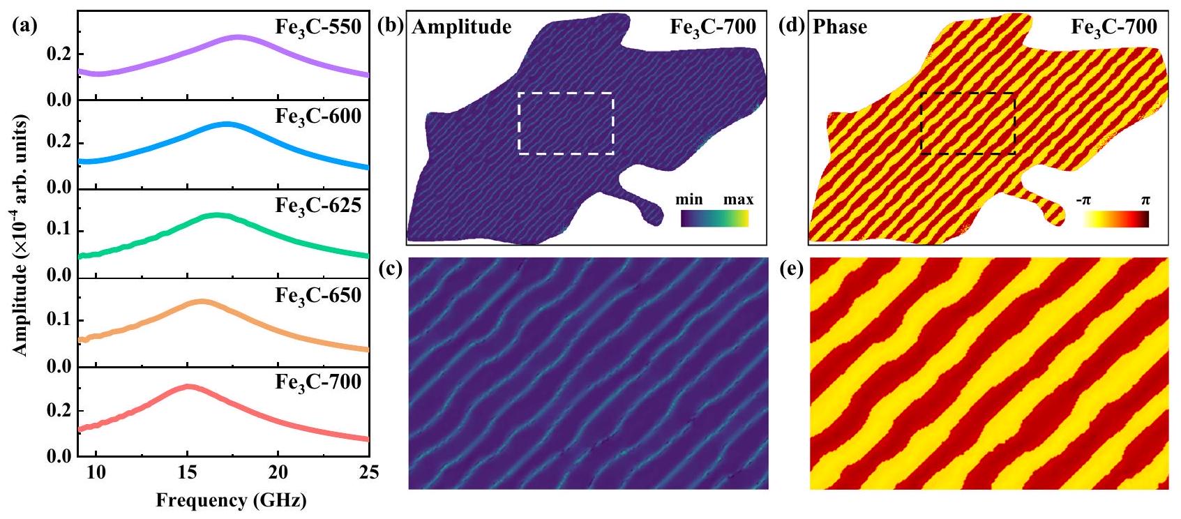
نتائج محاكاة الجزء التخيلي من النفاذية المعقدة لـ رقائق دقيقة تحت درجات حرارة مختلفة. توزيع السعة للرنين عند 15.1 جيجاهرتز لـ ميكروفليكس و عرض مكبر للمنطقة في الأبيض
مربع متقطع. توزيع الطور للرنين عند 15.1 جيجاهرتز لـ ميكروفليكس و عرض موسع للمنطقة في المربع الأسود المتقطع. يتم توفير بيانات المصدر كملف بيانات المصدر.

عملية ملاءمة النفاذية المعقدة

تمت معالجة ملاءمة النفاذية المعقدة لجميع العينات بواسطة OriginPro 2021 (9.8.0.200، شركة OriginLab). تم ملاءمة جميع خطوط الملاءمة بواسطة خمسة خطوط تجريبية مختلفة، وتم تعيين منطقة التردد عند يمكن ملاءمة النفاذية المعقدة استنادًا إلى معادلة لاندو-ليفسشيت الكلاسيكية كما يلي :
أين -1 هو القابلية الأولية، هو ثابت التخميد و هو تردد التشغيل. خلال عملية التركيب، ، و تم تعيينها كـ ، و ، والمتغيرات بما في ذلك ، و تم توظيفه لتناسب الثابت ، و . بالإضافة إلى ذلك، تردد الرنين الطبيعي يمكن الحصول عليه من خلال المعادلة كما يلي :
أين و تم الحصول عليها من عملية التناسب المذكورة أعلاه.

الحسابات النظرية

تم إجراء المحاكاة الميكرو مغناطيسية باستخدام المومكس المعلمات المادية هي كما يلي: الاستقطاب المغناطيسي هو ثابت التبادل . ثابت الأنيسوتروبي للخارج من المستوى ( ) وفي المستوى ( ) هي و ، على التوالي. تم تعيين السماكة على 20 نانومتر. ثابت التخميد هو ، الذي يتم الحصول عليه عن طريق حساب متوسط ثابت التخميد الملائم في الشكل 3ب، كما هو موضح في الجدول التكميلي 1. يجب ملاحظة أن في الـ
عادةً ما تؤثر المحاكاة على شدة السعة في موضع القمم الرنانة، مما لا يؤثر على موضع القمم الرنانة (انظر الشكل التكميلي 15) . وبالتالي، في المحاكاة الميكرو-mغناطيسية، يتم دراسة تأثير الأنيسوتروبي على الرنات المغناطيسية الفيرومغناطيسية من خلال تثبيت عند 0.1. حجم الشبكة هو تم الحصول على الهياكل المغناطيسية الثابتة من خلال تقليل الطاقة الكلية لنظام المغناطيس، بما في ذلك طاقة تبادل هايزنبرغ ( طاقة عدم التماثل طاقة إزالة المغناطيسية ( )، وطاقة زيمان تم الحصول على سلوكيات الديناميكا المغناطيسية في النظام المغناطيسي من خلال حل معادلة لاندو-ليفشيتز-غيلبرت (LLG):
أين هو الثابت الجيرومغناطيسي، يدل على متجه المغنطة، هو المجال الفعال ويمكن حسابه بواسطة حقل سينك عمودي تم تطبيقه لتحفيز ديناميات النظام المغناطيسي وتم إعطاؤه بالشكل التالي:
أين و سعة المجال ثابت عند 5 مللي تسلا. تحويل فورييه السريع (FFT) لـ تم استخدامه للحصول على طيف الرنين الفيرومغناطيسي. تم الحصول على توزيعات السعة والطور من خلال إجراء تحويل فورييه السريع (FFT) لكل شبكة في النظام المغناطيسي، حيث كانت الشدة عند 15.1 جيجاهرتز لـ تم رسم الميكروفليكس في طائرة.

توفر البيانات

البيانات التي تدعم نتائج هذه الدراسة متوفرة في النص الرئيسي والمعلومات التكميلية. البيانات الأصلية متاحة من المؤلف المراسل عند الطلب. البيانات المصدرية مرفقة مع هذه الورقة.

References

  1. Liang, L. et al. Multifunctional magnetic graphene aerogel with superior electromagnetic wave absorption performance. ACS Nano 15, 6622-6632 (2021).
  2. Man, Z. et al. Two birds with one stone: yolk-shell composite for high-performance sodium-ion energy storage and electromagnetic wave absorption. Nano Lett. 20, 3769-3777 (2020).
  3. Qin, M., Zhang, L., Zhao, X. & Wu, H. Lightweight Ni foam-based ultra-broadband electromagnetic wave absorber. Adv. Funct. Mater. 31, 2103436 (2021).
  4. Zhang, Y. et al. Broadband and tunable high-performance microwave absorption of an ultralight and highly compressible graphene foam. Adv. Mater. 27, 2049-2053 (2015).
  5. Gao, T. et al. Sub-nanometer Fe clusters confined in carbon nanocages for boosting dielectric polarization and broadband electromagnetic wave absorption. Adv. Funct. Mater. 32, 2204370 (2022).
  6. Li, Y. et al. Quinary high-entropy-alloy@graphite nanocapsules with tunable interfacial impedance matching for optimizing microwave absorption. Small 18, 2107265 (2022).
  7. Liu, D. et al. Rationally designed hierarchical N-doped carbon nanotubes wrapping waxberry-like Ni@C microspheres for efficient microwave absorption. J. Mater. Chem. A 9, 5086-5096 (2021).
  8. Di, J., Duan, Y., Pang, H., Jia, H. & Liu, X. Two-dimensional basalt/ni microflakes with uniform and compact nanolayers for optimized microwave absorption performance. ACS Appl. Mater. Interfaces 14, 51545-51554 (2022).
  9. Snoek, J. L. Gyromagnetic resonance in ferrites. Nature 160, 90-90 (1947).
  10. Iqbal, A. et al. Anomalous absorption of electromagnetic waves by 2D transition metal carbonitride (MXene). Science 369, 446-450 (2020).
  11. Cheng, M. et al. Transparent and flexible electromagnetic interference shielding materials by constructing sandwich AgNW@MXene/wood composites. ACS Nano 16, 16996-17007 (2022).
  12. Cheng, J. et al. Emerging materials and designs for low- and multiband electromagnetic wave absorbers: the search for dielectric and magnetic synergy? Adv. Funct. Mater. 32, 2200123 (2022).
  13. Wang, P. et al. Preparation and study of microflakes with easy-plane anisotropy and high working frequencies. Appl. Phys. Lett. 116, 112403 (2020).
  14. Zhang, S. et al. First-principles study of the easy-plane magnetocrystalline anisotropy in bulk HCP Co . J. Appl. Phys. 126, 083907 (2019).
  15. Kim, T. Y. & Park, C.-H. Magnetic anisotropy and magnetic ordering of transition-metal phosphorus trisulfides. Nano Lett. 21, 10114-10121 (2021).
  16. Chua, R. et al. Room temperature ferromagnetism of monolayer chromium telluride with perpendicular magnetic anisotropy. Adv. Mater. 33, 2103360 (2021).
  17. Zhang, C. et al. 3D printing of functional magnetic materials: from design to applications. Adv. Funct. Mater. 31, 2102777 (2021).
  18. Shi, C., Su, Y., Luo, Z., Zhang, J. & Zhang, H. Microwave absorption properties of spheres-assembled flake-like FeNi3 particles prepared by electrodeposition. J. Alloy Compd. 859, 157835 (2021).
  19. Li, X. et al. Morphology-controlled synthesis and excellent microwave absorption performance of ZnCo 2 O 4 nanostructures via a self-assembly process of flake units. Nanoscale 11, 2694-2702 (2019).
  20. Yang, W. et al. Tunable magnetic and microwave absorption properties of and their composites. Acta Mater. 145, 331-336 (2018).
  21. Ma, X., Duan, Y., Huang, L., Ma, B. & Lei, H. Multicomponent induced localized coupling in Penrose tiling for electromagnetic wave absorption and multiband compatibility. J. Mater. Sci. Technol. 130, 86-92 (2022).
  22. Zhang, Y. et al. Enhanced microwave absorption properties of barium ferrites by doping and oxygen-deficient sintering. J. Magn. Magn. Mater. 494, 165828 (2020).
  23. Xu, H. et al. Electromagnetic and microwave absorbing properties of the composites containing flaky FeSiAl powders mixed with in 1-18 GHz. J. Magn. Magn. Mater. 401, 567-571 (2016).
  24. Qing, Y. et al. Enhanced dielectric and electromagnetic interference shielding properties of ceramics by plasma spraying. J. Alloy Compd. 651, 259-265 (2015).
  25. Lei, C. & Du, Y. Tunable dielectric loss to enhance microwave absorption properties of flakey FeSiAl/ferrite composites. J. Alloy Compd. 822, 153674 (2020).
  26. Cai, Y., Wang, F., Zhang, Z. & Nestler, B. Phase-field investigation on the peritectic transition in Fe-C system. Acta Mater. 219, 117223 (2021).
  27. Liang, Y. et al. Kinetic behavior and microstructure of pearlite isothermal transformation under high undercooling. Met. Mater. Trans. A 49A, 4785-4797 (2018).
  28. Yasuda, H. et al. Dendrite fragmentation induced by massive-like transformation in Fe-C alloys. Nat. Commun. 10, 3183 (2019).
  29. Hao, X., Dong, J., Etim, I.-I. N., Wei, J. & Ke, W. Sustained effect of remaining cementite on the corrosion behavior of ferrite-pearlite steel under the simulated bottom plate environment of cargo oil tank. Corros. Sci. 110, 296-304 (2016).
  30. Tsybenko, H. et al. Deformation and phase transformation in polycrystalline cementite ( ) during single- and multi-pass sliding wear. Acta Mater. 227, 117694 (2022).
  31. Wu, Y. X., Sun, W. W., Styles, M. J., Arlazarov, A. & Hutchinson, C. R. Cementite coarsening during the tempering of Fe-C-Mn martensite. Acta Mater. 159, 209-224 (2018).
  32. Ping, D.-h, Chen, H. & Xiang, H. Formation of cementite via in Fe-C alloys. Cryst. Growth Des. 21, 1683-1688 (2021).
  33. Zhou, Y. T., Shao, X. H., Zheng, S. J. & Ma, X. L. Structure evolution of the interface mediated by cementite decomposition in cold-deformed pearlitic steel wires. J. Mater. Sci. Technol. 101, 28-36 (2022).
  34. Yamamoto, S. et al. Magnetocrystalline anisotropy of cementite pseudo single crystal fabricated under a rotating magnetic field. J. Magn. Magn. Mater. 451, 1-4 (2018).
  35. Li, Q. et al. Emerging magnetodielectric materials for 5 G communications: 18H hexaferrites. Acta Mater. 231, 117854 (2022).
  36. Ma, Z., Mohapatra, J., Wei, K., Liu, J. P. & Sun, S. Magnetic nanoparticles: synthesis, anisotropy, and applications. Chem. Rev. 123, 3904-3943 (2023).
  37. Zhang, X. F., Guan, P. F. & Dong, X. L. Transform between the permeability and permittivity in the close-packed Ni nanoparticles. Appl. Phys. Lett. 97, 033107 (2010).
  38. Deng, L. J. & Han, M. G. Microwave absorbing performances of multiwalled carbon nanotube composites with negative permeability. Appl. Phys. Lett. 97, 033107 (2010).
  39. Ma, T. Y. et al. Tuning the static and dynamic magnetic properties of c-axis oriented HCP-(Colr) thin films by the addition of Cr. Appl. Surf. Sci. 457, 598-603 (2018).
  40. Feng, H. et al. Static and dynamic magnetic properties of and material-modulated stripe-patterned thin films. J. Magn. Magn. Mater. 497, 166008 (2020).
  41. Liu, P. et al. Hollow engineering to Co@N-doped carbon nanocages via synergistic protecting-etching strategy for ultrahigh microwave absorption. Adv. Funct. Mater. 31, 2102812 (2021).
  42. Gao, Z. et al. Synergistic polarization loss of -based multiphase solid solution for electromagnetic wave absorption. Adv. Funct. Mater. 32, 2112294 (2022).
  43. Liu, J., Zhang, L. & Wu, H. Anion-doping-induced vacancy engineering of cobalt sulfoselenide for boosting electromagnetic wave absorption. Adv. Funct. Mater. 32, 2200544 (2022).
  44. Li, Y. et al. Improved microwave absorption properties by atomicscale substitutions. Carbon 139, 181-188 (2018).
  45. Li, Y. et al. Oxygen-sulfur co-substitutional Fe@C nanocapsules for improving microwave absorption properties. Sci. Bull. 65, 623-630 (2020).
  46. Fang, J. W. et al. Metal-organic framework-derived carbon/carbon nanotubes mediate impedance matching for strong microwave absorption at fairly low temperatures. ACS Appl. Mater. Interfaces 13, 33496-33504 (2021).
  47. Phuoc, N. N. & Ong, C. K. Thermal stability of high frequency properties of gradient-composition-sputtered FeCoHf films with and without stripe domains. J. Appl. Phys. 114, 023901 (2013).
  48. Ma, T. et al. Micrometer thick soft magnetic films with magnetic moments restricted strictly in plane by negative magnetocrystalline anisotropy. J. Magn. Magn. Mater. 444, 119-124 (2017).
  49. Vansteenkiste, A. et al. The design and verification of MuMax3. AIP Adv. 4, 107133 (2014).
  50. Volkov, V. V., Zhu, Y. & De Graef, M. A new symmetrized solution for phase retrieval using the transport of intensity equation. Micron 33, 411-416 (2002).
  51. Yu, Y. et al. Static and high frequency magnetic properties of FeGa thin films deposited on convex flexible substrates. Appl. Phys. Lett. 106, 162405 (2015).
  52. Wei, J. et al. An induction method to calculate the complex permeability of soft magnetic films without a reference sample. Rev. Sci. Instrum. 85, 054705 (2014).
  53. Hämäläinen, S. J., Madami, M., Qin, H., Gubbiotti, G. & Dijken, S. V. Control of spin-wave transmission by a programmable domain wall. Nat. Commun. 9, 4853 (2018).
  54. Bo, L., Hu, C., Zhao, R. & Zhang, X. Micromagnetic manipulation and spin excitation of skyrmionic structures. J. Phys. D Appl Phys. 55, 333001 (2022).

شكر وتقدير

يود المؤلفون أن يعبروا عن امتنانهم لصندوق العلوم الوطنية للباحثين الشباب المتميزين [رقم 52225312 (X.F.Z.)]، ومؤسسة العلوم الطبيعية الوطنية في الصين [الأرقام 52201202 (Y.X.L.) و U22A2O117 (Y.X.L.)]، ومؤسسة العلوم الطبيعية في مقاطعة تشجيانغ في الصين [الأرقام 2019C01121 (X.F.Z.) و 2021C01033 (X.F.Z.)].

مساهمات المؤلفين

Y.X.L. و X.F.Z. و G.W.Q. تصوروا الفكرة وصمموا العمل الحالي. R.Z.Z. و T.G. و Z.S. قاموا بالتحضير. Z.Y.Z. و R.Z.Z. و L.Z.J.
قام كل من C.L.H. و X.L.L. و Z.H.Z. بتنفيذ خصائص TEM. قام Z.Y.Z. و T.G. و Y.X.L. بإجراء قياسات امتصاص الميكروويف. قام R.Z.Z. و Y.X.L. بإجراء المحاكاة النظرية. ناقش جميع المؤلفين النتائج وساهموا في الورقة النهائية.

المصالح المتنافسة

يعلن المؤلفون عدم وجود مصالح متنافسة.

معلومات إضافية

معلومات إضافية النسخة الإلكترونية تحتوي على
المواد التكميلية متاحة على
https://doi.org/10.1038/s41467-024-45815-w.
يجب توجيه المراسلات والطلبات للحصول على المواد إلى يي شينغ لي أو شيوفينغ تشانغ.
معلومات مراجعة الأقران تشكر مجلة Nature Communications المراجعين المجهولين على مساهمتهم في مراجعة هذا العمل. يتوفر ملف مراجعة الأقران.
معلومات إعادة الطباعة والتصاريح متاحة علىhttp://www.nature.com/reprints
ملاحظة الناشر: تظل شركة سبرينغر ناتشر محايدة فيما يتعلق بالمطالبات القضائية في الخرائط المنشورة والانتماءات المؤسسية.
الوصول المفتوح هذه المقالة مرخصة بموجب رخصة المشاع الإبداعي النسب 4.0 الدولية، التي تسمح بالاستخدام والمشاركة والتكيف والتوزيع وإعادة الإنتاج بأي وسيلة أو صيغة، طالما أنك تعطي الائتمان المناسب للمؤلفين الأصليين والمصدر، وتوفر رابطًا لرخصة المشاع الإبداعي، وتوضح إذا ما تم إجراء تغييرات. الصور أو المواد الأخرى من طرف ثالث في هذه المقالة مشمولة في رخصة المشاع الإبداعي الخاصة بالمقالة، ما لم يُشار إلى خلاف ذلك في سطر الائتمان للمواد. إذا لم تكن المادة مشمولة في رخصة المشاع الإبداعي الخاصة بالمقالة وكان استخدامك المقصود غير مسموح به بموجب اللوائح القانونية أو يتجاوز الاستخدام المسموح به، فستحتاج إلى الحصول على إذن مباشرة من صاحب حقوق الطبع والنشر. لعرض نسخة من هذه الرخصة، قم بزيارةhttp://creativecommons.org/رخصة/بواسطة/4.0/.
(ج) المؤلف(ون) 2024

  1. معهد المواد المغناطيسية المتقدمة، كلية المواد والهندسة البيئية، جامعة هانغتشو ديانزي، هانغتشو 310012، الصين. المختبر الرئيسي للاتجاهية والنسيج للمواد (MOE)، كلية علوم وهندسة المواد، جامعة شمال شرق الصين، شنيانغ 110819، الصين.
    ساهم هؤلاء المؤلفون بالتساوي: رونغتشي تشاو، تونغ قاو. البريد الإلكتروني: liyx@mail.neu.edu.cn; zhang@hdu.edu.cn

Journal: Nature Communications, Volume: 15, Issue: 1
DOI: https://doi.org/10.1038/s41467-024-45815-w
PMID: https://pubmed.ncbi.nlm.nih.gov/38374257
Publication Date: 2024-02-19

Highly anisotropic microflakes constructed by solid-state phase transformation for efficient microwave absorption

Received: 14 March 2023
Accepted: 30 January 2024
Published online: 19 February 2024

Check for updates

Rongzhi Zhao © , Tong Gao , Yixing Li (B) , Zhuo Sun , Zhengyu Zhang , Lianze Ji’, Chenglong Hu’, Xiaolian Liu’, Zhenhua Zhang’, Xuefeng Zhang © Gaowu Qin (1)

Abstract

Soft magnetic materials with flake geometry can provide shape anisotropy for breaking the Snoek limit, which is promising for achieving high-frequency ferromagnetic resonances and microwave absorption properties. Here, twodimensional (2D) microflakes with crystal orientation are obtained by solid-state phase transformation assisted by electrochemical dealloying. The shape anisotropy can be further regulated by manipulating the thickness of 2D microflakes under different isothermally quenching temperatures. Thus, the resonant frequency is adjusted effectively from 9.47 and 11.56 GHz under isothermal quenching from to . The imaginary part of the complex permeability can reach 0.9 at 11.56 GHz , and the minimum reflection loss ( ) is with an effective absorption bandwidth ( ) of 2.55 GHz . This study provides insight into the preparation of high-frequency magnetic loss materials for obtaining highperformance microwave absorbers and achieves the preparation of functional materials from traditional structural materials.

Electromagnetic (EM) interference has emerged as a crucial problem with the rapid development of high-frequency communication techniques and micro-miniaturization of electronic information devices, which has aroused the rapid development of EM wave absorption materials . Among all these achievements, soft magnetic materials occupy an important position in designing materials because of their excellent magnetic loss abilities induced by high saturation magnetization . However, their ferromagnetic resonance behaviors could be impeded by the contradictory relationship between loss ability and frequency, known as the Snoek limit . Consequently, dielectric materials such as carbon, MXene, and ceramic have been introduced to obtain satisfactory EM wave absorption at gigahertz . However, an approach to cross the Snoek limit by manipulating the ferromagnetic materials themselves is still lacking, thus limiting the development of high-
frequency magnetic loss materials and the optimization of composited materials.
Shape anisotropy, which is constructed through controllable preparation processes, has been recognized as a promising pathway to address this shortcoming . The flake geometry could induce an effective in-plane anisotropy in soft magnetic materials to break the Snoek limit, which could optimize the magnetic loss ability at gigahertz . Under these guidelines, various soft magnetic materials, such as flake-like crystalline nanosheets , flakelike microflakes , and carbonyl iron microflakes , have been investigated, in which their ferromagnetic resonance frequencies have been extended to gigahertz regions. Nevertheless, it should be noted that their loss abilities, reflected by the imaginary part of the complex permeability ( ), still exhibit a decreasing tendency as the frequency increases to the
high-frequency region. For example, the values of , , and ferrite are , and 1.05 at , and 6.0 GHz , respectively. The values of , barium ferrite, and ceramics were reduced to and 0.48 at and . Therefore, a soft magnetic material with high ferromagnetic resonance frequency and magnetic loss capacity is urgently needed to meet the requirements of high-frequency applications.
Cementite ( ) with high saturation magnetization can be an ideal candidate to achieve the above requirements because of its high saturation. However, there remains a great lack of controllable synthesis of morphology through traditional chemistry methods because the structures of are difficult to restrict by coating agents. Here, we propose a pathway via solid-state phase transformation to obtain the large-scale preparation of microflakes with crystal orientation. The morphology can be adjusted by solid-state phase transformation, and the material can be obtained by electrochemical
dealloying at a constant voltage (CV) of -0.4 V . The electromagnetic response performances and theoretical simulations indicate that the ferromagnetic resonance frequency relies on the increased effective in-plane anisotropy induced by the flake geometry, which can be regulated by adjusting the isothermal quenching temperatures of eutectoid steels. As a result, the 2D microflakes treated at could achieve the highest anisotropy, which can achieve an excellent magnetic loss ability ( ) of 0.9 at a frequency of 11.56 GHz . Thus, our results clarify the relationship between anisotropy and high-frequency magnetic loss ability, proposing a new route for designing highperformance microwave absorption materials.

Results

According to the Fe-C binary phase diagram and the isothermal quenching curves of eutectoid steel ( ) (Fig. 1a), the microstructures of pearlite can be changed by the isothermal quenching process within the temperature regions of to the temperature of
Fig. 1 | Synthesis process (design route of solid-state phase transformation) of microflakes. a binary phase diagram and isothermal quenching curve of eutectoid steel and schematic illustrations of pearlite, sorbite, and troostite, and the white and blue stripes represent ferrite and , respectively. (A: austenite, B: bainite, F: ferrite, L: liquid, Ld/Ld’: ledeburite, M: martensite, P: pearlite,
: martensite finish, : martensite start, : average interlamellar distance) (b) Schematic illustrations of the electrochemical dealloying process and the morphology of microflakes, and the microflake (right) is derived from the blue cementite band (middle) after the dealloying process.
eutectoid transformation (marked by . The average interlamellar distance of different pearlite microstructures, so-called pearlite ( to ), sorbite ( ), and troostite ( ), can be evaluated by the empirical formula of refers to the difference between the heat treatment temperature and the isothermal quenching temperature) , which indicates that the thicknesses of cementite can be adjusted by designing the isothermal temperatures. In this context, the original eutectoid steels were first cut into a cuboid with a size of and annealed at for 3 h to completely austenitize. Then, the eutectoid steel precursors were placed into the molten salt to realize the isothermal quenching process, during which the austenite transformed into pearlite, sorbite, or troostite. Finally, the precursors were set as the electrode and connected to the electrochemical workstation in CV mode ( -0.4 V ). The microflakes, denoted as ( stands for quenching temperature), were prepared by electrochemical dealloying of the ferrite textures within a solution of KCl and , as illustrated in Fig. 1b. The corresponding current curves of the electrochemical dealloying process with decreasing tendencies can be recognized, as shown in Supplementary Fig. S1.
As shown in Fig. 2a, a typical pearlite structure can be observed in all the samples using scanning electron microscopy (SEM), in which the bright and dark stripes are the cementite and ferrite textures, respectively. The corresponding thicknesses of cementite were collected and summarized in Fig. 2e and Supplementary Fig. 2. The thicknesses decreased from 22.0 to 15.7 nm as the quenching temperatures decreased from 700 to , implying that the structures can be manipulated by the isothermal quenching process. The microstructures of the eutectoid steel precursors after the dealloying process ( ) were characterized by SEM and shown in Supplementary Fig. 3. It can be seen that the ferrite has been etched, and the precursor was constructed by the flake structural cementite. Subsequently, the microstructures of the 2D microflakes were characterized by SEM and transmission electron microscopy (TEM), as shown in Fig. 2b, c. Here, an irregular flake structure could be observed in all the samples. It can be noticed that the thickness of Fe 3 C is nanoscale, but the width and length are microscale, which results in a high aspect ratio for reinforcing the shape anisotropy to enhance natural resonance performance. The elemental distributions and crystalline structures of were detected by energy-dispersive X-ray
Fig. 2 | Microstructure characterizations. a SEM images of eutectoid steel isothermal quenching under different temperatures, scale bar: . b Highresolution SEM images of the , and micro-flakes, scale bar: . c High-resolution TEM image, atomic EDS maps, and SAED image of -700 microflakes, scale bar: . d Schematic diagram of pearlite,
electrochemical dealloying process, and analysis directions. e Summarization of the thickness of microflakes (Fitting line: ). The number refers to the isothermal quenching temperature, and source data are provided as a Source Data file.
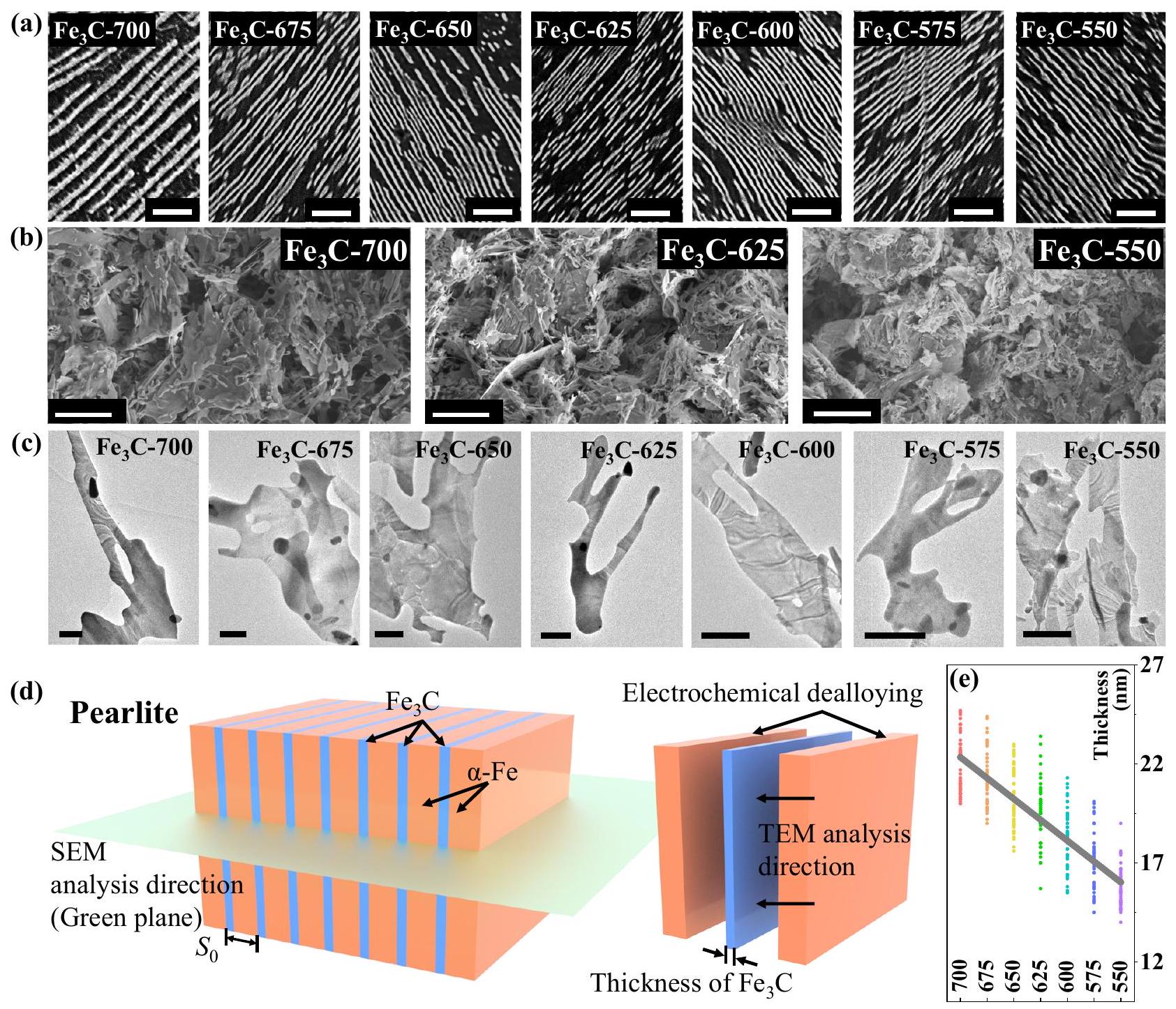
spectroscopy (EDS) and X-ray diffraction (XRD), respectively (Supplementary Figs. S4 and S5). The schematic diagram of pearlite has been exhibited in Fig. 2d and the corresponding definition of thickness has been displayed. Two composed elements, carbon, and iron, were uniformly distributed in the microflakes, and their phase structures were highly identical to the standard phase card PDF#85-1317 , indicating that the 2D microflakes were successfully obtained through the electrochemical dealloying process.
Using spherical aberration-corrected TEM, we further investigated the microstructures of these 2D microflakes, in which highresolution TEM (HR-TEM) images of , and were obtained and shown in Supplementary Fig. 6. As the atomic EDS mapping demonstrated, the iron and carbon atoms are uniformly posited in the 2D microflakes. The enlarged view of HR-TEM images and the corresponding inverse fast Fourier transform (IFFT) images (Supplementary Fig. S6B) further disclose the lattice structures of , in which the red spots represent iron atoms and the blue spots are carbon. It can be found that the zone axis of all the is [010], which has been identified by the selected area electron diffraction (SAED) images shown in Supplementary Figs. S6A and S7 . It is concluded that the crystal structure of 2D microflakes is orthorhombic with the space group of Pnma. The magnetocrystalline anisotropy can be inferred, where the easy axis of [001] is located in the plane of 2D microflakes and the second easy axis of [010] is located out-of-plane . Thus, the intrinsic in-plane anisotropy introduced by the solid-state phase transformation assisted by electrochemical dealloying can effectively improve the magnetic loss ability in the high-frequency region.
The magnetic performances of all the samples were analyzed through the hysteresis loops, as exhibited in Supplementary Figs. S8 and S9. The saturation magnetizations ( ) are 97.7, 103.5, 114.6, , and , respectively, and the coercivities are , and 69.6 Oe. The increased with the enhanced thicknesses of microflakes, while the exhibited an inverse phenomenon. The microflakes presented the highest among all the samples. Because the coercivity is proportional to the anisotropy constant , it can be inferred that the increase in coercivity is the consequence of the increased anisotropies of the 2D microflakes. Thus, the shape anisotropy can be efficiently manipulated by adjusting the isothermal quenching conditions .
The microwave response performances of all the microflakes were measured by a vector network analyzer (VNA) in the frequency region of , as demonstrated in Supplementary Figs. S10 and S11. The measurements of each sample were repeated more than 5 times. In general, the dielectric loss ability should not be observed in the single magnetic loss material. In all the microflakes, it can be seen that the complex permittivity values of the real parts ( ) are approximately centered at 20 and the imaginary parts ( ) are centered at 0 . However, some resonance peaks can be noticed in the complex permittivity patterns, both in real and imaginary parts. To clearly demonstrate the position of these resonance peaks, the superimposed figure of complex permittivity and complex permeability has been employed and shown in Supplementary Fig. 12. It can be noticed that the values can be found in two areas: the high-frequency turning point of the real part, and both ends of the resonance peak of the imaginary part. Such a phenomenon is mainly associated with the transformation between the permittivity and permeability, which is realized by the connection between the microflakes because of their high anisotropy microstructures . According to studies such as close-packed Ni nanoparticles, multiwalled carbon nanotubes, and sub-nanometer clusters in nanocages, the aggregation of conductive medium would construct the conductive network, resulting in a reinforced polarization behavior for increasing the dielectric loss ability . Therefore, the irregular
shape of microflakes would form a conductive network in the EM testing sample, which can induce polarization around the natural resonance and thus result in the vibration of complex permittivity.
From the results of the complex permeability, typical ferromagnetic resonances can be found in all the samples, and their frequencies are within the regions of . The complex permeability of all the samples was fitted through the Landau-Lifshitz-Gilbert (LLG) equation based on five different experimental results, and the details of the fitting process have been demonstrated in the method section. Here, an increased resonance peak ( ) can be observed along with the decreased isothermal temperature (Fig. 3a, b). It can be noticed that the of -700 microflakes, containing the lowest magnetic anisotropy of all the samples, can even reach 9.73 GHz , which is far higher than that of previously reported soft magnetic materials such as c-axis oriented hcp-(Colr) thin films and materialmodulated stripe-patterned thin films ( 5.8 GHz , and and their composites . The results indicate that the magnetic loss abilities can be significantly optimized in the 2D microflakes by adjusting the isothermal temperature, ascribed to the manipulation of shape anisotropies. In the optimized microflakes, which present the highest anisotropy, can be enhanced to 11.56 GHz (Fig. 3c). For the magnetic loss ability (imaginary part of the complex permeability, , the values of all the microflakes reached 1.05, , and 0.90 at , 11.00 , and 11.56 GHz , respectively. The magnetic loss abilities of microflakes can be effectively improved in high-frequency regions compared with the , ferrites ( 0.31 , , and . Furthermore, to visually illustrate the optimized magnetic loss abilities, the pattern of versus of microflakes was compared to the other reported magnetic loss materials in Fig. 3d (Supplementary Refs. 1-26), in which the samples with increased anisotropy could possess satisfactory magnetic loss performances at gigahertz among the related reports. Furthermore, the magnetic loss angles were calculated by the complex permeability to further imply the loss performances of microflakes (Fig. 3e). Similar to the complex permeability, the loss abilities were improved along with the increased anisotropy.
The microwave absorption properties of the 2D microflakes were evaluated by transmit-line theory , as shown in Fig. 3c and Supplementary Fig. 13. The minimum reflection loss ( ) values of are , and -56.99 dB , respectively, in which -10 and -20 dB indicate that and incident EM energy can be attenuated . For the effective absorption bandwidth ( ), the values of , 3.75 , and 2.69 GHz with thicknesses of , and 1.35 mm can be observed. The 2D microflakes exhibit excellent microwave absorption performance only through their magnetic loss abilities. For the impedance-matching performances of microflakes, the values of were collected and are shown in Supplementary Fig. 14. Commonly, the values in the regions of 0.8 and 1.2 should be considered as excellent impedance-matching performances . Here, the 2D microflakes could obtain satisfactory matching performances in the entire frequency region ( ), indicating that the manipulation of shape anisotropy could simultaneously improve the impedance matching and microwave absorption performances in high-frequency regions.
Therefore, it is concluded that a high-frequency magnetic loss ability can be achieved in microflakes with enhanced shape anisotropy. To further identify the details of such performances, Lorentz transmission electron microscopy (L-TEM) was employed, and the corresponding in-focus (Fig. 4a, b) and overfocus (Fig. 4c, d) images are shown, in which strip domain structures can be observed in the microflakes. The nucleation of strip domains can result from the appearance of intrinsic out-of-plane anisotropy, which is similar to the manipulation of magnetic domains in sputtered (or evaporated)
Fig. 3 | Magnetic loss abilities. a Real part ( ) and imaginary part ( ) of the complex permeability at the frequency regions of , in which the colored fitted lines are fitted from the experimental lines (gray lines) through the Landau-Lifshitz-Gilbert (LLG) equation. c Summarization of the natural resonance frequencies (Fitting line: ), effective absorption
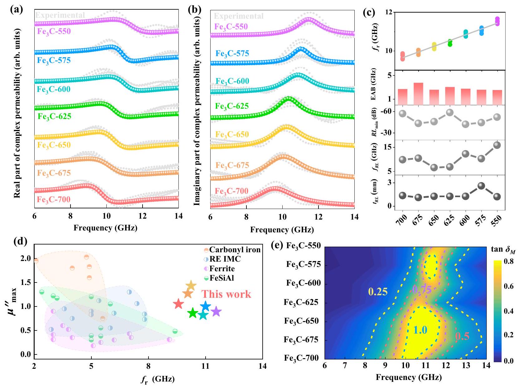
bandwidth, reflection loss and the corresponding thickness of . d Comparison of versus of reported soft magnetic materials and . e The tan of microflakes in the frequency region of . Source data are provided as a Source Data file.
magnetic thin films by adjusting the perpendicular anisotropy . The strip domain structures under a static magnetic field ( ) can be reconstructed by micromagnetic simulations with mumax by considering the shape anisotropy as an effective in-plane anisotropy , as shown in Fig. 4e. The color denotes the x-component of magnetization. The simulated results are consistent with the calculated distribution of magnetization from contrast L-TEM images by the classic transport of intensity equation (TIE) method (see Fig. 4f). Thus, the ferromagnetic resonance behaviors of microflakes under different temperatures can also be obtained from the static magnetic domains by solving the Landau-Lifhiz-Gilbert equation numerically.
Figure 5a shows the ferromagnetic resonance spectra of the microflakes under different temperatures after obtaining the static magnetic structures with different values of , which are induced by the shape anisotropy of microflakes with different thicknesses. The resonant frequencies of the simulated microflakes increase from 15.1 GHz to 17.8 GHz with the increase in from to with an interval of , in which the chosen values of are considered for fitting the change in coercivity (Supplementary Figs. S8 and S9) and the change in frequency is consistent with the experimental results. The difference between the simulation and experimental values of frequency could result from the defect in a real material system, where the ideal material model is considered in micromagnetic simulations. Thus, it is inferred that the increased
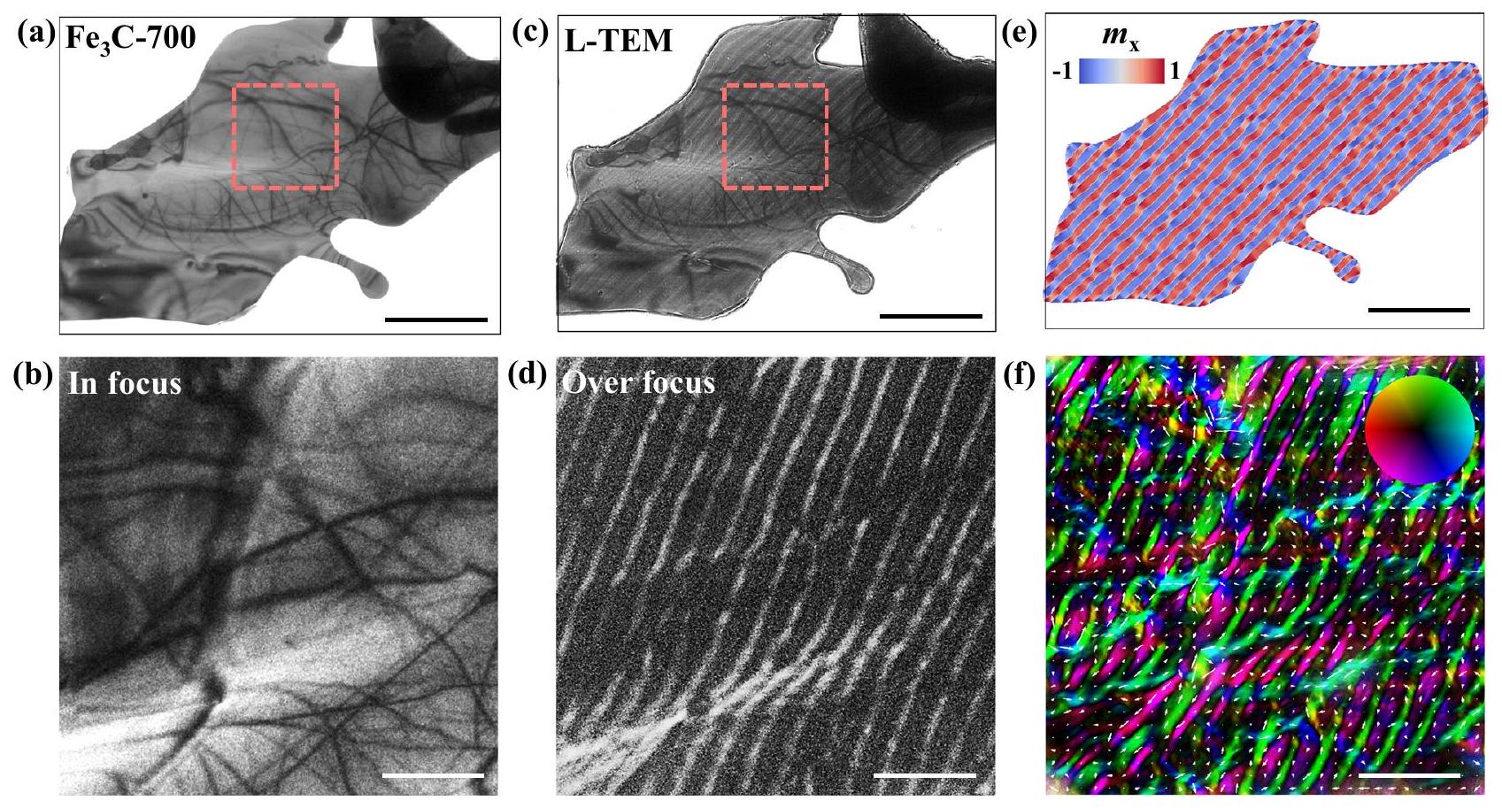
resonant frequencies can be ascribed to the increase in effective inplane anisotropy induced by flake geometries, which can be manipulated by adjusting the isothermal quenching temperatures. Furthermore, the amplitude distribution of resonance at 15.1 GHz for the -700 microflakes is shown in Fig. 5b, c, which is focused on the position of domain walls and named localized spin wave modes. Therefore, the absorption of EM for microflakes at high frequency could originate from the appearance of large numbers of domain walls in stripe domains. The corresponding phase distribution of the microflakes is also shown in Fig. 5d, e. The phase is almost uniform in a single domain wall, which is similar to the propagation of spin waves vertically along the domain wall.

Discussion

In summary, 2D anisotropic microflakes with crystal orientations were prepared from eutectoid steel precursors through solid-state phase transformation assisted by electrochemical dealloying. It can be recognized that the high-frequency ferromagnetic resonance behavior is strictly correlated to the shape anisotropy, which can be manipulated by adjusting the isothermal quenching temperatures. The stripe domain structures are observed directly without a biased magnetic field using in situ L-TEM, which can be reconstructed by micromagnetic simulations with in-plane and out-of-plane anisotropies. Consequently, the natural resonance frequencies of microflakes have been increased to the regions of , while the mostly
micromagnetic simulations, scale bar: . Calculated distribution of magnetization from contrast L-TEM images by the classic transport of intensity equation (TIE) method, and the color denotes the x-component of magnetization, scale bar: 500 nm . Source data are provided as a Source Data file.
Fig. 4 | L-TEM characterizations of -700 microflakes. a In-focus L-TEM images and enlarged view of the red dashed square, scale bar: 500 nm . c Overfocus L-TEM images (scale bar: ) and enlarged view of the red dashed square (scale bar: 500 nm ). e Simulated distribution of magnetization by
optimized microflakes can reach 11.56 GHz with a value of 0.9. Moreover, the and of microflakes could reach and , respectively, exhibiting an optimized microwave absorption property. The present study provides an intrinsic insight into the role of anisotropy in high-frequency magnetic loss ability and provides a new route to design high-performance microwave absorption materials. Furthermore, this method can stimulate research interests in obtaining functional materials from other traditional structural materials. We believe that this work also provides some preliminary research basis for the realization of structural-functional integrated materials.

Methods

Electrochemical dealloying for synthesizing micro-flakes

The eutectoid steel ( ) was firstly cut into the blocks with the size of and annealed at for 3 h in the ambient atmosphere. Then, the blocks were placed into the molten salt for 30 min to suffer the isothermal quenching process. Here, the isothermal temperature was achieved by two different salt groups (wt%): (i) for and , (ii) for to . After that, the blocks were fixed as an electrode in the solution of KCl and to engage the electrochemical dealloying process for 48 h . The electrochemical dealloying process was obtained by an electrochemical workstation working in constant voltage (CV) mode with a voltage of -0.4 V . The as-made micro-flakes were washed with the mixture of and ethanol ( ) and the deionized water for several times and then dried in the vacuum drying oven for 12 h .

Structural characterizations

The scanning electron microscope (SEM) was characterized by the JEOL JSM-IT500HR/LA with an accelerating voltage of 20 kV . The microstructure and morphology of the micro-flakes were characterized by the field-emission transmission electron microscope (FE-TEM)
(Thermo Scientific Talos F200S), and the energy-dispersive X-ray spectroscopy (EDS) was obtained by Bruker Super Lite X2. The highresolution TEM images were obtained by the spherical aberrationcorrected transmission electron microscope (JEOL ARM-200). The statistic of the micro-flake thickness is calculated via the SEM images using the open-access ImageJ software. The crystalline structure of micro-flakes was calculated by the open-access VESTA software. The magnetic properties were measured via the vibrating sample magnetometer (VSM, ADE EV9) with a maximum applied field of 15 kOe . The Lorentz transmission electron microscope (L-TEM) images under a static magnetic field were analyzed by Thermo Scientific Talos F200S. X-ray diffraction (XRD) was performed using a SmartLab9kW (Rigaku) with a scan step of .

Electromagnetic response performances

The electromagnetic response performance was obtained by the vector network analyzer (VNA, N5222A, Keysight Co., Ltd.) equipped with a Type-N coaxial airline ( , Ceyear CETC). The VNA was calibrated by the 2-port short-open-load-thru (SOLT) calibration standard (85054B), and the samples were uniformly mixed with the paraffin at a weight percentage of and then processed to a toroidal shape of 7.00 mm outer diameter and 3.04 mm inner diameter. The reflection loss (RL) and efficient absorption bandwidth (EAB) were calculated via the transmit-line theory using the following equations (S3 and S4) .
In with is normalized input impedance, is the light velocity in the free space, is the frequency, and is the thickness of the absorber.
Fig. 5 | Simulated ferromagnetic resonance behaviors of microflakes.
a Simulated results of the imaginary part of the complex permeability for microflakes under different temperatures. Amplitude distribution of resonance at 15.1 GHz for the microflakes and enlarged view of the region in the white
dashed square. d Phase distribution of resonance at 15.1 GHz for the microflakes and enlarged view of the region in the black dashed square. Source data are provided as a Source Data file.

Fitting process of complex permeability

The fitting of the complex permeability of all the samples has been processed by OriginPro 2021 (9.8.0.200, OriginLab Corporation). All the fitting line is fitted by five different experimental lines, and the frequency region was set at . The complex permeability can be fitted based on the classical LLG as follows :
Where -1is the initial susceptibility, is the damping constant and is the operating frequency. During the fitting process, the , and have been set as , and , and the variates including , and have been employed to fit the constant , and . In addition, the natural resonance frequency can be obtained through the equation as follows :
Where the and are obtained from the above fitting process.

Theoretical calculations

The micromagnetic simulations were conducted using the mumax . The material parameters are the following: The saturation magnetization is . The exchange constant . The anisotropy constant of out-of-plane ( ) and inplane ( ) are and , respectively. The thickness is set as 20 nm . The damping constant is , which is obtained by averaging the fitted damping constant in Fig. 3b, as shown in Supplementary Table 1. It should be noted that the in the
simulation usually affects the intensity of amplitude in the position of resonant peaks, which does not affect the position of resonant peaks (see Supplementary Fig. 15) . Thus, in micromagnetic simulations, the influence of anisotropy on ferromagnetic resonances is studied by fixing at 0.1 . The mesh size is . The static magnetic structures were obtained by minimizing the total energy of the magnetic system, including Heisenberg exchange energy ( ), anisotropy energy ( ), demagnetization energy ( ), and Zeeman energy . The magnetization dynamical behaviors in the magnetic system were obtained by solving the Landau-Lifshitz-Gilbert (LLG) equation:
where is the gyromagnetic constant, denotes the magnetization vector, is the effective field and can be calculated by . A perpendicular sinc field was applied to excite the dynamics of the magnetic system and was given by the following:
where and . The field amplitude is fixed at 5 mT . The fast Fourier transform (FFT) of was used to obtain the ferromagnetic resonance spectra. The amplitude and phase distributions were obtained by performing the FFT of every mesh in the magnetic system, where the intensity at 15.1 GHz for the microflakes was plotted in the plane.

Data availability

The data that support the findings of this study are provided in the main text and the Supplementary Information. The original data are available from the corresponding author upon request. Source data are provided with this paper.

References

  1. Liang, L. et al. Multifunctional magnetic graphene aerogel with superior electromagnetic wave absorption performance. ACS Nano 15, 6622-6632 (2021).
  2. Man, Z. et al. Two birds with one stone: yolk-shell composite for high-performance sodium-ion energy storage and electromagnetic wave absorption. Nano Lett. 20, 3769-3777 (2020).
  3. Qin, M., Zhang, L., Zhao, X. & Wu, H. Lightweight Ni foam-based ultra-broadband electromagnetic wave absorber. Adv. Funct. Mater. 31, 2103436 (2021).
  4. Zhang, Y. et al. Broadband and tunable high-performance microwave absorption of an ultralight and highly compressible graphene foam. Adv. Mater. 27, 2049-2053 (2015).
  5. Gao, T. et al. Sub-nanometer Fe clusters confined in carbon nanocages for boosting dielectric polarization and broadband electromagnetic wave absorption. Adv. Funct. Mater. 32, 2204370 (2022).
  6. Li, Y. et al. Quinary high-entropy-alloy@graphite nanocapsules with tunable interfacial impedance matching for optimizing microwave absorption. Small 18, 2107265 (2022).
  7. Liu, D. et al. Rationally designed hierarchical N-doped carbon nanotubes wrapping waxberry-like Ni@C microspheres for efficient microwave absorption. J. Mater. Chem. A 9, 5086-5096 (2021).
  8. Di, J., Duan, Y., Pang, H., Jia, H. & Liu, X. Two-dimensional basalt/ni microflakes with uniform and compact nanolayers for optimized microwave absorption performance. ACS Appl. Mater. Interfaces 14, 51545-51554 (2022).
  9. Snoek, J. L. Gyromagnetic resonance in ferrites. Nature 160, 90-90 (1947).
  10. Iqbal, A. et al. Anomalous absorption of electromagnetic waves by 2D transition metal carbonitride (MXene). Science 369, 446-450 (2020).
  11. Cheng, M. et al. Transparent and flexible electromagnetic interference shielding materials by constructing sandwich AgNW@MXene/wood composites. ACS Nano 16, 16996-17007 (2022).
  12. Cheng, J. et al. Emerging materials and designs for low- and multiband electromagnetic wave absorbers: the search for dielectric and magnetic synergy? Adv. Funct. Mater. 32, 2200123 (2022).
  13. Wang, P. et al. Preparation and study of microflakes with easy-plane anisotropy and high working frequencies. Appl. Phys. Lett. 116, 112403 (2020).
  14. Zhang, S. et al. First-principles study of the easy-plane magnetocrystalline anisotropy in bulk HCP Co . J. Appl. Phys. 126, 083907 (2019).
  15. Kim, T. Y. & Park, C.-H. Magnetic anisotropy and magnetic ordering of transition-metal phosphorus trisulfides. Nano Lett. 21, 10114-10121 (2021).
  16. Chua, R. et al. Room temperature ferromagnetism of monolayer chromium telluride with perpendicular magnetic anisotropy. Adv. Mater. 33, 2103360 (2021).
  17. Zhang, C. et al. 3D printing of functional magnetic materials: from design to applications. Adv. Funct. Mater. 31, 2102777 (2021).
  18. Shi, C., Su, Y., Luo, Z., Zhang, J. & Zhang, H. Microwave absorption properties of spheres-assembled flake-like FeNi3 particles prepared by electrodeposition. J. Alloy Compd. 859, 157835 (2021).
  19. Li, X. et al. Morphology-controlled synthesis and excellent microwave absorption performance of ZnCo 2 O 4 nanostructures via a self-assembly process of flake units. Nanoscale 11, 2694-2702 (2019).
  20. Yang, W. et al. Tunable magnetic and microwave absorption properties of and their composites. Acta Mater. 145, 331-336 (2018).
  21. Ma, X., Duan, Y., Huang, L., Ma, B. & Lei, H. Multicomponent induced localized coupling in Penrose tiling for electromagnetic wave absorption and multiband compatibility. J. Mater. Sci. Technol. 130, 86-92 (2022).
  22. Zhang, Y. et al. Enhanced microwave absorption properties of barium ferrites by doping and oxygen-deficient sintering. J. Magn. Magn. Mater. 494, 165828 (2020).
  23. Xu, H. et al. Electromagnetic and microwave absorbing properties of the composites containing flaky FeSiAl powders mixed with in 1-18 GHz. J. Magn. Magn. Mater. 401, 567-571 (2016).
  24. Qing, Y. et al. Enhanced dielectric and electromagnetic interference shielding properties of ceramics by plasma spraying. J. Alloy Compd. 651, 259-265 (2015).
  25. Lei, C. & Du, Y. Tunable dielectric loss to enhance microwave absorption properties of flakey FeSiAl/ferrite composites. J. Alloy Compd. 822, 153674 (2020).
  26. Cai, Y., Wang, F., Zhang, Z. & Nestler, B. Phase-field investigation on the peritectic transition in Fe-C system. Acta Mater. 219, 117223 (2021).
  27. Liang, Y. et al. Kinetic behavior and microstructure of pearlite isothermal transformation under high undercooling. Met. Mater. Trans. A 49A, 4785-4797 (2018).
  28. Yasuda, H. et al. Dendrite fragmentation induced by massive-like transformation in Fe-C alloys. Nat. Commun. 10, 3183 (2019).
  29. Hao, X., Dong, J., Etim, I.-I. N., Wei, J. & Ke, W. Sustained effect of remaining cementite on the corrosion behavior of ferrite-pearlite steel under the simulated bottom plate environment of cargo oil tank. Corros. Sci. 110, 296-304 (2016).
  30. Tsybenko, H. et al. Deformation and phase transformation in polycrystalline cementite ( ) during single- and multi-pass sliding wear. Acta Mater. 227, 117694 (2022).
  31. Wu, Y. X., Sun, W. W., Styles, M. J., Arlazarov, A. & Hutchinson, C. R. Cementite coarsening during the tempering of Fe-C-Mn martensite. Acta Mater. 159, 209-224 (2018).
  32. Ping, D.-h, Chen, H. & Xiang, H. Formation of cementite via in Fe-C alloys. Cryst. Growth Des. 21, 1683-1688 (2021).
  33. Zhou, Y. T., Shao, X. H., Zheng, S. J. & Ma, X. L. Structure evolution of the interface mediated by cementite decomposition in cold-deformed pearlitic steel wires. J. Mater. Sci. Technol. 101, 28-36 (2022).
  34. Yamamoto, S. et al. Magnetocrystalline anisotropy of cementite pseudo single crystal fabricated under a rotating magnetic field. J. Magn. Magn. Mater. 451, 1-4 (2018).
  35. Li, Q. et al. Emerging magnetodielectric materials for 5 G communications: 18H hexaferrites. Acta Mater. 231, 117854 (2022).
  36. Ma, Z., Mohapatra, J., Wei, K., Liu, J. P. & Sun, S. Magnetic nanoparticles: synthesis, anisotropy, and applications. Chem. Rev. 123, 3904-3943 (2023).
  37. Zhang, X. F., Guan, P. F. & Dong, X. L. Transform between the permeability and permittivity in the close-packed Ni nanoparticles. Appl. Phys. Lett. 97, 033107 (2010).
  38. Deng, L. J. & Han, M. G. Microwave absorbing performances of multiwalled carbon nanotube composites with negative permeability. Appl. Phys. Lett. 97, 033107 (2010).
  39. Ma, T. Y. et al. Tuning the static and dynamic magnetic properties of c-axis oriented HCP-(Colr) thin films by the addition of Cr. Appl. Surf. Sci. 457, 598-603 (2018).
  40. Feng, H. et al. Static and dynamic magnetic properties of and material-modulated stripe-patterned thin films. J. Magn. Magn. Mater. 497, 166008 (2020).
  41. Liu, P. et al. Hollow engineering to Co@N-doped carbon nanocages via synergistic protecting-etching strategy for ultrahigh microwave absorption. Adv. Funct. Mater. 31, 2102812 (2021).
  42. Gao, Z. et al. Synergistic polarization loss of -based multiphase solid solution for electromagnetic wave absorption. Adv. Funct. Mater. 32, 2112294 (2022).
  43. Liu, J., Zhang, L. & Wu, H. Anion-doping-induced vacancy engineering of cobalt sulfoselenide for boosting electromagnetic wave absorption. Adv. Funct. Mater. 32, 2200544 (2022).
  44. Li, Y. et al. Improved microwave absorption properties by atomicscale substitutions. Carbon 139, 181-188 (2018).
  45. Li, Y. et al. Oxygen-sulfur co-substitutional Fe@C nanocapsules for improving microwave absorption properties. Sci. Bull. 65, 623-630 (2020).
  46. Fang, J. W. et al. Metal-organic framework-derived carbon/carbon nanotubes mediate impedance matching for strong microwave absorption at fairly low temperatures. ACS Appl. Mater. Interfaces 13, 33496-33504 (2021).
  47. Phuoc, N. N. & Ong, C. K. Thermal stability of high frequency properties of gradient-composition-sputtered FeCoHf films with and without stripe domains. J. Appl. Phys. 114, 023901 (2013).
  48. Ma, T. et al. Micrometer thick soft magnetic films with magnetic moments restricted strictly in plane by negative magnetocrystalline anisotropy. J. Magn. Magn. Mater. 444, 119-124 (2017).
  49. Vansteenkiste, A. et al. The design and verification of MuMax3. AIP Adv. 4, 107133 (2014).
  50. Volkov, V. V., Zhu, Y. & De Graef, M. A new symmetrized solution for phase retrieval using the transport of intensity equation. Micron 33, 411-416 (2002).
  51. Yu, Y. et al. Static and high frequency magnetic properties of FeGa thin films deposited on convex flexible substrates. Appl. Phys. Lett. 106, 162405 (2015).
  52. Wei, J. et al. An induction method to calculate the complex permeability of soft magnetic films without a reference sample. Rev. Sci. Instrum. 85, 054705 (2014).
  53. Hämäläinen, S. J., Madami, M., Qin, H., Gubbiotti, G. & Dijken, S. V. Control of spin-wave transmission by a programmable domain wall. Nat. Commun. 9, 4853 (2018).
  54. Bo, L., Hu, C., Zhao, R. & Zhang, X. Micromagnetic manipulation and spin excitation of skyrmionic structures. J. Phys. D Appl Phys. 55, 333001 (2022).

Acknowledgements

The authors gratefully acknowledge the National Science Fund for Distinguished Young Scholars [No. 52225312 (X.F.Z.)], the National Natural Science Foundation of China [Nos. 52201202 (Y.X.L.) and U22A2O117 (Y.X.L.)] and the Natural Science Foundation of Zhejiang Province of China [Nos. 2019C01121 (X.F.Z.) 2021C01033 (X.F.Z.)].

Author contributions

Y.X.L., X.F.Z. and G.W.Q. conceived the idea and designed the present work. R.Z.Z., T.G. and Z.S. carried out the preparation. Z.Y.Z., R.Z.Z, L.Z.J.,
C.L.H., X.L.L. and Z.H.Z. carried out the TEM characteristics. Z.Y.Z., T.G. and Y.X.L. performed the microwave absorption measurements. R.Z.Z. and Y.X.L. performed the theoretical simulation. All authors discussed the results and contributed to the final paper.

Competing interests

The authors declare no competing interests.

Additional information

Supplementary information The online version contains
supplementary material available at
https://doi.org/10.1038/s41467-024-45815-w.
Correspondence and requests for materials should be addressed to Yixing Li or Xuefeng Zhang.
Peer review information Nature Communications thanks the anonymous reviewers for their contribution to the peer review of this work. A peer review file is available.
Reprints and permissions information is available at http://www.nature.com/reprints
Publisher’s note Springer Nature remains neutral with regard to jurisdictional claims in published maps and institutional affiliations.
Open Access This article is licensed under a Creative Commons Attribution 4.0 International License, which permits use, sharing, adaptation, distribution and reproduction in any medium or format, as long as you give appropriate credit to the original author(s) and the source, provide a link to the Creative Commons licence, and indicate if changes were made. The images or other third party material in this article are included in the article’s Creative Commons licence, unless indicated otherwise in a credit line to the material. If material is not included in the article’s Creative Commons licence and your intended use is not permitted by statutory regulation or exceeds the permitted use, you will need to obtain permission directly from the copyright holder. To view a copy of this licence, visit http://creativecommons.org/ licenses/by/4.0/.
(c) The Author(s) 2024

  1. Institute of Advanced Magnetic Materials, College of Materials and Environmental Engineering, Hangzhou Dianzi University, Hangzhou 310012, China. Key Laboratory for Anisotropy and Texture of Materials (MOE), School of Materials Science and Engineering, Northeastern University, Shenyang 110819, China.
    These authors contributed equally: Rongzhi Zhao, Tong Gao. e-mail: liyx@mail.neu.edu.cn; zhang@hdu.edu.cn