طبقة ثنائية ذاتية التجميع لخلايا الشمسية من البيروفسكايت مع تحسين التحمل ضد الضغوط الحرارية Self-assembled bilayer for perovskite solar cells with improved tolerance against thermal stresses
يتطلب اعتماد خلايا الشمسية من نوع بيروفسكايت (PSCs) تحسين المقاومة لدرجات الحرارة العالية وتغيرات الحرارة. لقد مكنت الطبقات الذاتية التجميع المختارة للثقوب (SAMs) من تحقيق تقدم في أداء خلايا PSCs المقلوبة، ومع ذلك قد تؤثر سلبًا على استقرار الحرارة بسبب الانفصال وضعف الاتصال بين الواجهات. هنا قمنا بتطوير طبقة ثنائية ذاتية التجميع من خلال الربط التساهمي لطبقة SAM من حمض الفوسفونيك مع طبقة علوية من ثلاثي الفينيل أمين. هذه الشبكة البوليمرية، التي تشكلت من خلال تفاعل فريدل-كرافتس، قاومت التحلل الحراري حتى لمدة 200 ساعة. في هذه الأثناء، أظهر الطبقة العلوية الموجهة نحو الوجه تلامسًا لاصقًا مع البيروفيسكايت، مما أدى إلى تحسين بمقدار 1.7 مرة في طاقة الالتصاق مقارنة بواجهة SAM-البيروفيسكايت. أبلغنا عن كفاءات تحويل الطاقة التي تتجاوز لـ PSCs المقلوبة. أظهرت الأجهزة الرائدة أقل من و فقدان الكفاءة بعد 2000 ساعة من التعرض للرطوبة العالية و الرطوبة النسبية) وأكثر من 1200 دورة حرارية بين و على التوالي، تفي بمعايير استقرار درجة الحرارة الموضحة في معايير اللجنة الكهروتقنية الدولية 61215:2021.
لقد جذبت خلايا الشمسية البيروفيسكايت (PSCs) اهتمام الباحثين بفضل كفاءتها العالية في تحويل الطاقة (PCE) وإنتاجها الفعال من حيث التكلفة.. ومع ذلك، فإن دخولهم السوق يعتمد على إثبات الاستقرار على المدى الطويل تحت مختلف الضغوط البيئية. تلعب درجة الحرارة دورًا حاسمًا في استقرار خلايا الطاقة الشمسية، مع إمكانية حدوث تدهور حراري نتيجة للمكونات العضوية المتطايرة، وهجرة الأيونات، والواجهات الحساسة عند درجات حرارة مرتفعة.علاوة على ذلك، يمكن أن تتسبب تقلبات درجات الحرارة في تراكم إجهاد غير مرن وفشل ميكانيكي بسبب عدم تطابق معاملات التمدد الحراري بين الطبقات في الأجهزة..
في صناعة الخلايا الشمسية السيليكونية، يتم تقييم التدهور الحراري والميكانيكي الحراري من خلال الحرارة الرطبةو
85% رطوبة نسبية (RH) ودورات حرارية (بين و اختبارات، وفقًا لمعايير اللجنة الكهروتقنية الدولية (IEC) 61215:2021“، على التوالي. حتى الآن، هناك تقارير محدودة عن كفاءة خلايا الطاقة الشمسية العضوية التي تتحمل كلا من اختبارات الشيخوخة المعجلة.
يمكن أن تُعزى التقدمات الأخيرة في أداء واستقرار خلايا الطاقة الشمسية الهجينة جزئيًا إلى استخدام الطبقات الأحادية المجمعة ذاتيًا (SAMs) كجهات اتصال مختارة للثقوب (HSCs) في بنية جهاز مقلوبة.تحدث تشكيلات SAM بشكل عفوي من خلال تفاعلات التكثيف غير المتجانسة بين الأحماض الفوسفونية والأسطح المعدنية المؤكسدة المائية.. هذا يعدل الهياكل الإلكترونية لأكاسيد المعادن، مما يقلل من عدم تطابق مستويات الطاقة عند الواجهة. بالمقارنة
مع طبقات نقل الثقوب التقليدية التي تحتوي على مواد مضافة متنقلة وامتصاصية للرطوبة، تعزز طريقة SAM استقرار خلايا الطاقة الشمسية..
ومع ذلك، فإن استقرار درجة الحرارة يمثل مصدر قلق للـ SAMs الانتقائية؛ حيث أن الأحماض الفوسفونية المحتوية على الكاربازول المستخدمة بشكل شائع عرضة للاضطراب الحراري والانفصال عند درجات حرارة تتجاوز (المراجع 6، 19، 25). بالإضافة إلى ذلك، يؤثر الاتصال بين البيروفسكايت وSAMs على قوة الالتصاق عند الواجهة، مما يؤثر على الاستقرار الميكانيكي لخلايا الطاقة الشمسية البيروفسكايتية ضد تقلبات درجة الحرارة.توجد عدة استراتيجيات لمعالجة القضايا المتعلقة بإجهاد الحرارة. على سبيل المثال، يمكن أن يؤدي ضبط ربط مجموعات الرأس بأسطح الركيزة إلى تحسين استقرار الأغشية الذاتية التنظيم عند درجات الحرارة العالية.استخدام المواد المساعدة على الامتصاص، والروابط ثنائية الوظيفة، والطبقات الفائقة الرطوبة يمكن أن يحقق تلامسًا لاصقًا بين البيروفيسكايت وSAMs، مما يمنع نمو الشقوق أثناء دورات الحرارة..
نظرًا لهذه التطورات الواعدة، فإن اتباع نهج شامل يعد ضروريًا لتعزيز القوة الحرارية والميكانيكية لواجهة SAM/البيروفسكايت في الوقت نفسه. ومع ذلك، قد يقيّد ذلك قابلية تطبيق العديد من SAMs الكلاسيكية التي تتمتع باستقرار حراري محدود.. في الوقت نفسه، يجب أن تأخذ تطوير مواد السطح الانتقائية الجديدة في الاعتبار تفاعلات مجموعة الرأس، وتوافق مجموعة النهاية مع البيروفسكايت، والتشكيل واللحظات ثنائية القطب، مما يزيد من التعقيد في تصميمها وتصنيعها..
هنا، استكشفنا الطبقات الثنائية ذات التجميع الذاتي (SABs) نظرًا لإمكاناتها في ضبط الوظائف بشكل أكثر تنوعًا. تمثل SABs شكلًا أساسيًا من الطبقات المتعددة ذات التجميع الذاتي، وتتكون من طبقات أحادية متميزة ذات مكونات متنوعة مترابطة عبر روابط تساهمية أو أيونية.تجمع هذه الطبقات طبقة تلو الأخرى لتثبيت الطبقة الأحادية غير المستقرة من خلال إدخال مكونات صلبة، مما يتيح التحكم في إنهاء الفيلم.. ومع ذلك، على الرغم من أنه تم الإبلاغ عن هياكل ثنائية الطبقات لخلايا الطاقة الشمسية، إلا أنها تعتمد على تفاعلات فان der Waals الثانوية.لقد استنتجنا أن تشكيل SAB المرتبط بروابط تساهمية يتطلب تنشيطًا كيميائيًا لأسطح الطبقة الأحادية السفلية لتجديد المواقع التفاعلية (على سبيل المثال، مجموعات الهيدروكسيل وحمض الفوسفونيك).ومع ذلك، فإن هذه العملية غير متوافقة مع الأغشية الذاتية الانتقائية للثقوب التي تحتوي على مجموعة طرفية مترافقة.
تكوين SAB عبر ألكلة فريدل-كرافتس
استخدمنا طبقة أساسية من SAM انتقائية للثقب، تتكون من حمض 2-(9H-كاربازول-9-يل)إيثيل) الفوسفونيك (2PACz)، لتطوير SABs. لتمكين الارتباط التساهمي لطبقة علوية تم إيداعها بشكل متسلسل، قمنا بالتحقيق فيتفاعلات تشكيل الروابط لمجموعة الكاربازول الطرفية. يُلاحظ أن طرق التخليق العضوي الشائعة، مثلتفعيل وتفاعل سوزوكي للكربازولات الهالوجينية، يعتمد على محفزات المعادن الانتقالية؛ ومع ذلك، يمكن أن تؤدي هذه إلى إدخال تلوث معدني في معالجة الخلايا الشمسية الرقيقة. لذلك، ركزنا على الألكلة باستخدام طريقة فريدل-كرافتس الخالية من المعادن.
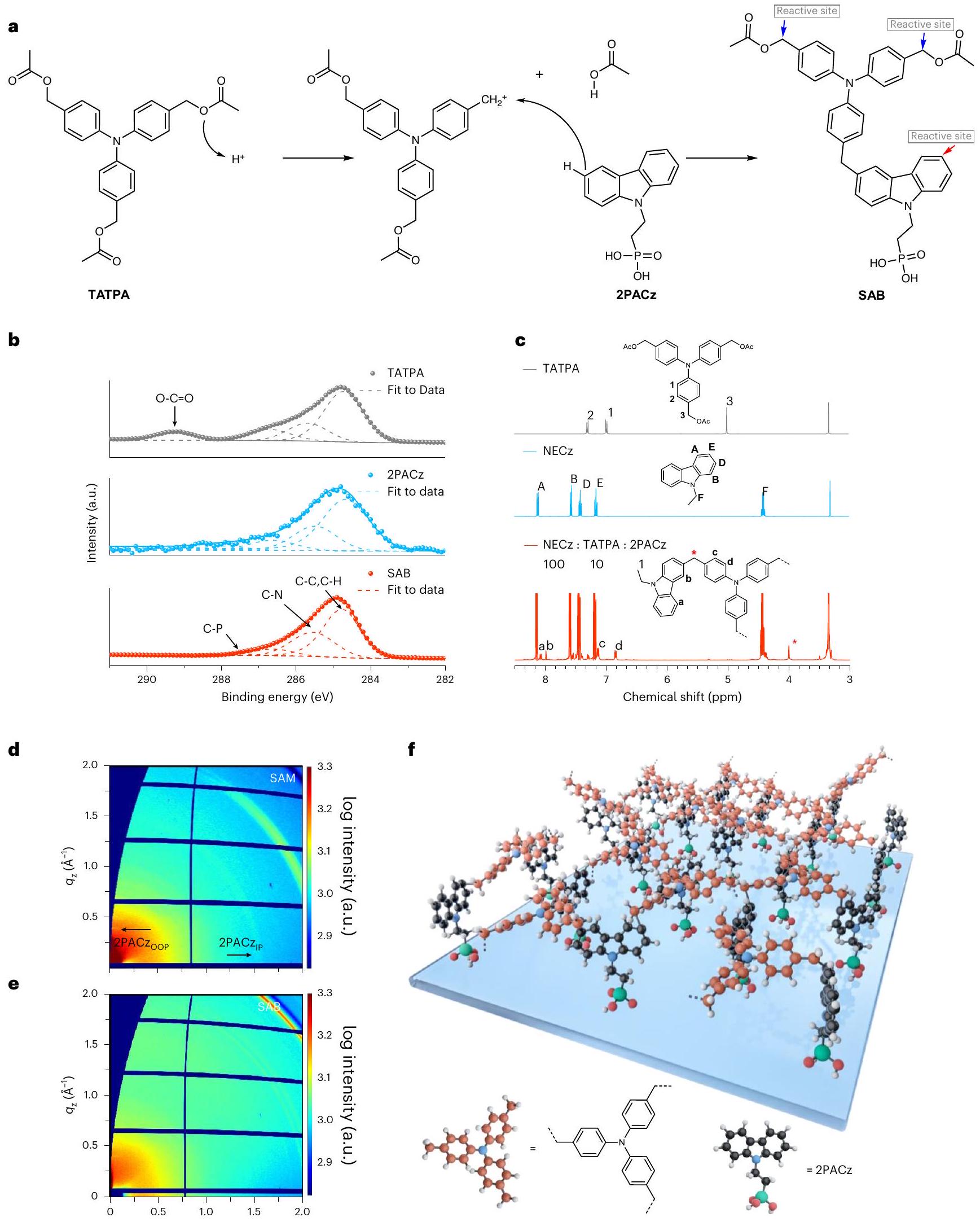
تم ترسيب عامل الألكلة، 4، 4’، 4′-تريس(أسيتوكسي ميثيلين)تري فينيل أمين (TATPA)، على ركائز أكسيد الإنديوم والقصدير (ITO) المعدلة بـ 2PACz باستخدام معالجة المحلول. تم استخدام TATPA في تفاعلات الربط الضوئي، حيث تقوم الأحماض الضوئية بتحفيز الانقسام غير المتجانس لـرابطة، مما ينتج كربوكاتيون تفاعلي يعمل كإلكتروفيل لاستبدال الكاربازول، تحديدًا في مواضع C3 أو C6 النوكليوفيلية (الشكل 1أ). تتوج هذه العملية بعملية ألكلة فريدل-كرافتس للثلاثي فينيل أمين (TPA) إلى الكاربازولات، مما يشكل شبكة بوليمرية (الشكل التكميلي 1). افترضنا أن هذه التفاعلات المتقاطعة قد تحدث بشكل تلقائي على أغشية 2PACz ذاتية التنظيم مع الأحماض الفوسفونية التي تعمل كمانح للبروتون..
قمنا بدراسة التحول الكيميائي لـ TATPA على كل من سطح ITO العاري وسطح ITO-2PACz باستخدام مطيافية الإلكترونيات الضوئية بالأشعة السينية (XPS) ومطيافية الأشعة تحت الحمراء بتحويل فورييه مع الانعكاس الكلي المخفف (ATR-FTIR). كشفت طيف XPS لـ C 1s عن قمة مميزة عند 289.2 eV على سطح ITO المغطى بـ TATPA، تعود إلى كربونات الكربونيل لـ TATPA، إلى جانب قمم مميزة لـ و روابط، تشير إلى تفاعل كيميائي محدود (الشكل 1ب و
الشكل التوضيحي الإضافي 2). على النقيض من ذلك، كانت قمة الكربونيل غائبة في طبقة 2PACz-TATPA الثنائية بعد المعالجة الحرارية عند“، مما يدل على تحلل مجموعات الإستر أثناء التفاعلات الصلبة على الركيزة (الشكل التكميلي 3أ). أكدت تقنية ATR-FTIR هذه النتائج، حيث أظهرت انخفاضًا في نطاق تمدد كربونيل الإستر لـ TATPA (عند ) عند تفاعله مع سطح ITO-2PACz (الشكل التكميلي 3b). اقترحنا أن تفكك TATPA تم بدءه بواسطة المتبقيالمجموعات داخل طبقة 2PACz، كما يتضح من وجود الاهتزازات (عند و ) في طيف ATR-FTIR المقابل (الشكل التوضيحي 4)تم الإشارة إلى تكوين وسائط الكربوكاتيون بشكل أكبر من خلال الميثوكسيليشن لمنتج TATPA المتحلل باستخدام الميثانول المؤشر، مما يسهل على الأرجح عملية ألكلة فريدل-كرافتس (الملاحظة التكميلية 1 والأشكال التكميلية 5 و6).
للكشف المباشر عن تفاعلات الربط المتقاطع، قمنا بإجراء قياسات طيف الكتلة للأيونات الثانوية بتقنية الوقت الطولي (TOF-SIMS) على الركائز (الشكل التوضيحي 7a). لم يكشف طيف الكتلة لركيزة ITO-2PACz عن أي شظايا جزيئية قابلة للاكتشاف مع نسبة الكتلة إلى الشحنة (نسب تتجاوز 700 (الشكل التوضيحي 7ب). بالمقابل، أظهر ثنائي الطبقة 2PACz-TATPA قممًا متعددة تتجاوز نطاقات الكتلة للمكونات الفردية. ومن الجدير بالذكر أن هناك قممًا مميزة تتركز عندوتم تحديد 804.3، والتي نعزوها إلى منتجات اقتران من نوع فريدل-كرافتس مرتبطة بجسور ميثيلين (الشكل التوضيحي الإضافي 7c).
تم إجراء الرنين المغناطيسي النووي (NMR) كطريقة غير مدمرة للتحقق من الهياكل الجزيئية. قمنا في البداية بتحضير عينة NMR عن طريق كشط فيلم مختلط من TATPA و 2PACz (بنسبة وزن 1:1) لجمع المسحوق. ومع ذلك، كانت هناك صعوبات في إذابة هذه المواد الصلبة في ثنائي ميثيل سلفوكسيد (DMSO) أو كلوروبنزين (CB) مما أعاق تحليل NMR في الحالة السائلة (الشكل التكميلي 8). للتخفيف من البلمرة الزائدة،-إيثيلكاربازول (NECz)، النظير غير الحمضي لـ 2PACz، تم استخدامه كالمتفاعل الرئيسي، مع الاحتفاظ بكمية صغيرة من 2PACz (نسبة وزن 1:100 إلى NECz) لتحفيز تحلل TATPA. البروتونكشف طيف الرنين المغناطيسي النووي لهذا المزيج المعدل عن قمة مفردة عند (أي، بروتونات)وغياب إشارة الميثيلين لـ TATPA (“; H-3)، مما يدل على استبدال الأروماتية الكهربية. وهذا مدعوم بالتحول في إشارات بروتون الأروماتية نحو المجال الأعلى، الانتقال من H-1 ( ) و H-2 ( ) من TATPA إلى و في المنتج المتقاطع، على التوالي (الشكل 1c). لوحظ اتجاه مشابه للبروتونات في مواضع C4 وC5 (أي، H-aromatic) من الكاربازولات (الشكل 1c والأشكال التكميلية 9-12).
بالإضافة إلى ذلك، استكشفنا نظيرًا أقل تفاعلية من TATPA، 4-(دي-“-توليل أمين) بنزيل أسيتات (DTBA)، الذي يحتوي على مجموعة استر واحدة (الشكل التكميلي 13). من المتوقع أن تفاعل سطحه مع 2PACz ينتج جزيئًا منفصلًا، (2-(3،6-ثنائي (4-(دي-حمض الفوسفونيك (DTBA-2PACz) (9H-carbazol-9-yl)ethyl) (benzyl)-9-(tolylamino)، مما يسهل تحديد المنتج (الشكل التكميلي 13). قمنا بصب فيلم مختلط من 2PACz وDTBA على ركائز زجاجية وقمنا بتسخينه.أكدت مطيافية الكتلة عالية الدقة تشكيل DTBA-2PACz، حيث تم الكشف عن الخصائص المميزةأيون فيفي وضع الأيونات الموجبة وأيون فيفي وضع الأيون السالب، كلاهما يتوافق مع أوزانهم الجزيئية المحسوبة (الشكل التكميلي 14).كشف تحليل NMR للفيلم المذاب في DMSO المؤشر عن بروتون الجسر الميثيلي عند (الشكل التكميلي 15). أكدت طيفية التماسك الكمي الأحادي غير النووي هذه التعيين الهيكلي، موضحة الارتباط عند و (الشكل التوضيحي الإضافي 16) spectroscopy correlation homonuclear حددت المزيد من الارتباطات بين بروتون الميثيلين ( ) والبروتونات المجاورة من وحدات الكاربازول وTPA عند و على التوالي (الشكل التوضيحي 17)، مما يدعم آلية ألكلة فريدل-كرافتس
الشكل 1| بناء وهيكل SAB. أ، الآلية المقترحة لتفاعل الاقتران بين TATPA و 2PACz. ب، طيف XPS لأفلام TATPA و 2PACz و SAB، حيث تمثل الخطوط الصلبة التوافق مع البيانات وتظهر الخطوط المتقطعة المكونات الفردية، كل منها متوافق مع توزيع غاوسي. ج،طيف NMR لـ TATPA و NECz ومزيج من NECz و TATPA و 2PACz. في الزاوية: كيميائي تظهر هياكل TATPA وNECz و2PACz مع تسميات تتوافق مع قمم NMR.د، هـ، أنماط GIWAXS ثنائية الأبعاد لـ 2PACz (د) و SAB (هـ). IP، في المستوى؛ OOP، خارج المستوى. إشارات الحيود معتُنسب إلى ركائز ITO.رسم تخطيطي يوضح هيكل SAB.
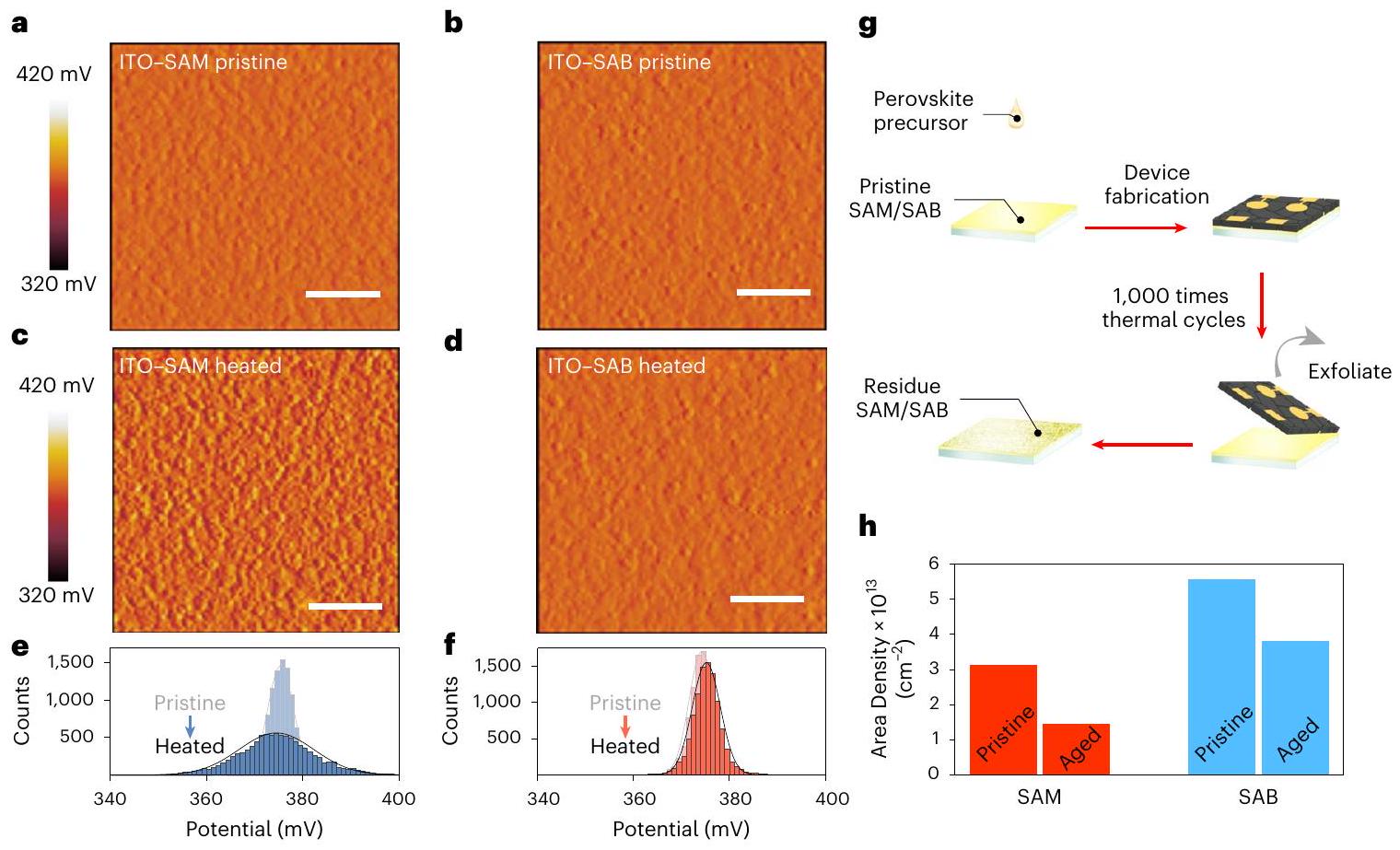
الشكل 2 | استقرار درجة الحرارة لـ SAB. أ-د، صور الجهد السطحي للاتصالات الجزيئية. أ،ب، ITO/SAM النقي (أ) و ITO/SAB (ب) قبل المعالجة الحرارية عندلـITO/SAM (ج) و ITO/SAB (د) بعد المعالجة الحرارية فيلمدة 200 ساعة. قضبان القياس، 500 نانومتر. e، f، التوزيعات الإحصائية المحتملة لأسطح ITO-2PACz (e) وITO-SAB (f). توزيعات غاوسية. مناسبة لمنحنيات البيانات. ج، توضيحات لإجراء إعداد العينة لقياس تغطية الاتصال الجزيئي، قبل وبعد تطبيق إجهاد الدورة الحرارية.كثافة المساحة لجهات الاتصال الجزيئية المختلفة، كما تم تحديدها باستخدام نهج كيميائي كهربائي. (ملاحظة إضافية 2). بالإضافة إلى ذلك، تم إظهار أن عامل الألكلة الآخر، (([1،1′-ثنائي الفينيل]-4،4′-دييلبيس(أزانيترييل))تتراكيس(بنزين-4،1-دييل)) تتراكيس(ميثيلين) تتراستات، bisTATPA)، الذي يتميز بنواة TPA مرتبطة، يتفاعل مع 2PACz (الشكل التكميلي 18). كما وُجد أن نهج SAB قابل للتطبيق بشكل عام على مختلف SAMs من حمض الفوسفونيك التي تسمح بالهجوم الكهربي بواسطة الكربوكاتيونات (ملاحظة إضافية 3 والأشكال التكملية 18-23)
تمت دراسة ترتيب الجزيئات والبنية البلورية للطبقات السطحية باستخدام تقنية تشتت الأشعة السينية بزاوية ضئيلة (GIWAXS). بالنسبة لطبقة 2PACz الأحادية، لاحظنا نمط قوس تشتت يمتد من الاتجاه الأفقي (عندإلى زاوية أفقية منمقترحًا محاذاة عمودية لجزيئات 2PACz، على الرغم من وجود توزيع في زوايا الميل (الشكل 1d، الشكل التوضيحي 24 والملاحظة التكميلية 4). من المحتمل أن يكون هذا الترتيب في المستوى مدفوعًا بـتكديس جزيئات 2PACz، كما يتضح من تراجع ميل الجزيئات في فيلم مرجعي كثيف التعبئة (الشكل التكميلي 25 والملاحظة التكملية 4). أدى ترسيب TATPA إلى تعطيل البلورية الجانبية لطبقة 2PACz، كما يتضح من اختفاء قمة الانكسار في المستوى (الشكل 1e). بالإضافة إلى ذلك، تم ملاحظة اتساع ميل الجزيئات في الفيلم المرجعي عالي الكثافة المعالج بـ TATPA (الشكل التكميلي 26).
هنا، تشمل التفاعلات السائدةتكوين الرابطة بين 2PACz وTATPA، مما أدى إلى ترتيب أفقي لوحدات TPA فوق 2PACz. تم تأكيد الاتجاه المواجه للوجه بواسطةتكديس القمة على-مقابل لـتكرارية وحدات TPA المتكررة – لوحظت عند تركيز أعلى من محلول TATPA (الشكل التكميلي 27 والملاحظة التكمالية 5). تم الإشارة إلى إعادة تنظيم السطح بشكل أكبر من خلال قياسات مجهر القوة باستخدام مسبار كيلفن (KPFM) (الشكل التكميلي 28)؛ حيث أظهر ثنائي الطبقة 2PACz/ TATPA المعالج حرارياً توزيعًا أضيق في فرق الجهد الكهربائي عند التلامس (CPD) مقارنةً بنظيره غير المعالج حرارياً (الشكل التكميلي 29)، مما يُعزى إلى تغطية جزيئية أكثر تجانسًا.من خلال دمج هذه النتائج، افترضنا أن علاج TATPA أدى إلى هيكل SAB مترابط تساهميًا، مع 2PACz غير المرتبطة كجزيء مرتبط بالسطح، مرتبط بطبقة TPA مستوية كإنهاء الفيلم (الشكل 1a، f).
استقرار درجة الحرارة للاتصالات الجزيئية
استخدمنا KPFM لتقييم الاستقرار الحراري للاتصالات الجزيئية على أسطح ITO. أظهرت الأسطح المعدلة بـ SAMs و SABs قيم CPDs متقاربة، بمتوسط 375 مللي فولت لكل من العينتين (الشكل 2a، b). وقد عزونا ذلك إلى التأثير الطفيف لطبقة TPA على تغييرات وظيفة العمل، ربما بسبب توجيهها في المستوى، وبالتالي، ثنائي القطب الصافي القليل في الاتجاه العمودي.. بعد التلدين الحراري في لوحظ تدهور حراري في أغشية 2PACz SAMs لمدة 200 ساعة، مما يدل على زيادة في تباينات CPD من 23 مللي فولت إلى 60 مللي فولت. بالمقابل، حافظت الأسطح المعدلة بـ SAB على توزيع محتمل موحد في خريطة CPD المعنية (مع قيمة تباين CPD تبلغ 30 مللي فولت)، مما يشير إلى تقليل التغيرات الهيكلية في الاتصالات الجزيئية (الشكل 2c-f).
تم تقييم استقرار التدوير الحراري للاتصالات الجزيئية من خلال قياسات الفولتمترية الدورية (CV). تم قياس كثافة السطح للطبقات الرقيقة الذاتية (SAMs) قبل وبعد الخضوع لـ 1,000 دورة حرارية منإلى، انخفض من إلىجزيئات، مما يشير إلى فقدان في التغطية (الشكل 2 ج، ح، الشكل التكميلية 30 والملاحظة التكميلية 6). بالإضافة إلى ذلك، كشفت مطيافية الأشعة السينية المشتتة للطاقة عن زيادة في محتوى الفوسفور منإلىعلى جانب البيروفيسكايت من الواجهة المدفونة بعد دورة حرارية (الشكل التكميلي 31). وعلى العكس، فإن الشبكة البوليمرية داخل SABs منحت مقاومة أفضل للتخلص تحت تقلبات الحرارة، مما أدى إلى فقدان أقل في التغطيةوانخفض ارتباط الأحماض الفوسفونية مع البيروفسكايت (الشكل التكميلي 31). كما لوحظ أن SABs أظهرت كثافة سطحية أولية أعلى منجزيئاتمقارنةً مع SAMs، التي نسبناها إلى تضمين وحدات TPA النشطة كيميائيًا.
توصيف واجهة البيروفسكايت-SAM أو البيروفسكايت-SAB
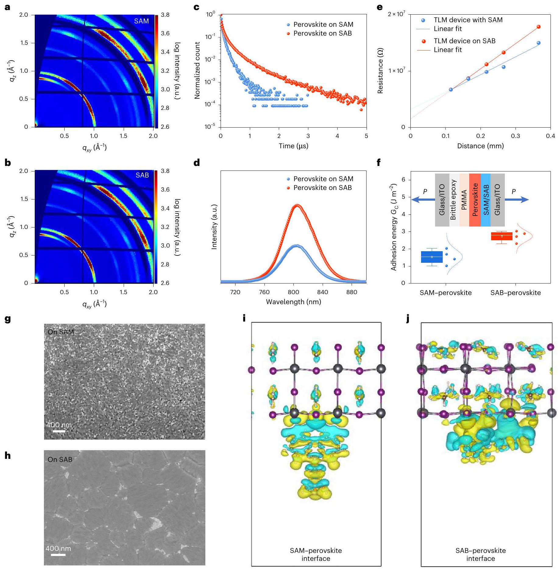
لقد زوّرناأفلام البيروفسكايت على ركائز ITO المعدلة بـ SAM أو SAB عبر عملية حل واحدة مدعومة بمذيب مضاد. كشفت صور المجهر الإلكتروني الماسح (SEM) من الأعلى عن أحجام حبوب متوسطة متشابهة (675 نانومتر لـ SAM مقابل 720 نانومتر لـ SAB) وسطح خالٍ من الثقوب لكل من الأفلام (الشكل التوضيحي 32). أظهر تحليل GIWAXS أنماط تشتت متطابقة تقريبًا، مع توجيه مفضل لمستويات (100) من البيروفسكايت الأسود. و زوايا الأفق، وذروة الشوائب عند (الشكل 3 أ، ب والشكل التكميلي 33). على الرغم من هذه التشابهات في شكل السطح والبنية الكتلية، أظهرت البيروفسكايت على الركائز المعدلة بـ SAB عمر انحلال ضوئي (PL) مطول في قياسات PL الزمنية المحسوبة (TRPL)، مع زيادة المتوسطات من 484 نانوثانية إلى عبر أربع نقاط مستقلة لكل عينة (عند تدفق تحفيزي من ) (الشكل 3c والشكل التكميلي 34)، مقارنةً بتلك الموجودة على الركائز المعدلة بـ SAM. وهذا يدل على تقليل إعادة التركيب غير الإشعاعي، وهو ما تم تأكيده بشكل أكبر من خلال نتائج عائد الكم للضوء المنبعث (الشكل 3d، الشكل التكميلي 35 والملاحظة التكملية 7). علاوة على ذلك، باستخدام نموذج خط النقل، أظهرت واجهات الـ SAB-بيروفسكايت مقاومة تماس أقل من مقارنة مع للنظائر المعتمدة على SAM (الشكل 3e والشكل التكميلي 36). استنتجنا أن الواجهة بين البيروفسكايت وSABs كانت أقل عيبًا وأظهرت خصائص كهربائية محسّنة مقارنةً بواجهة البيروفسكايت-SAM.
تم استخدام مطيافية الإلكترونات الضوئية فوق البنفسجية (UV) لتحديد الحد الأقصى لحزمة التكافؤ (VBM) وعملية العمل للبيروفسكايت وHSCs (الشكل التوضيحي 37). تم تقدير الحد الأدنى لحزمة التوصيل باستخدام فجوة الطاقة البصرية من مطيافية الأشعة فوق البنفسجية-المرئية. بالنسبة لركائز ITO-SAB، وُجد أن عملية العمل وVBM أقل بمقدار 60 ميلي إلكترون فولت و100 ميلي إلكترون فولت على التوالي، مقارنة بركائز ITO-SAM. وبالتالي، تم تقليل فرق VBM بين SAB والبيروفسكايت بمقدار 40 ميلي إلكترون فولت بالنسبة لـ SAM، مما يدل على تقليل خسائر الطاقة عند الواجهات المدفونة..
تم تقييم السلامة الميكانيكية لواجهة الاتصال بين البيروفسكايت والجزيئات باستخدام اختبارات ميكانيكا كسر الشعاع المزدوج (DCB). قمنا بإعداد عينة DCB عن طريق لصق شريط زجاجي على طبقة البيروفسكايت المحمية بواسطة بوليمر الميثيل ميثاكريلات باستخدام إيبوكسي هش (الشكل التوضيحي 38). طاقة الالتصاقتم الحصول عليه من قياسات القوة والإزاحة وفقًا لمنهجية تم الإبلاغ عنهاالمتوسط عند واجهة البيروفسكايت-SAB كانت عبر أربع جولات من الاختبارات،أعلى من ذلك عند واجهة البيروفسكايت-SAMلأربع جولات من الاختبارات)، مما يشير إلى تحسين الاستقرار الميكانيكي (الشكل 3f). تم ملاحظة نتائج مماثلة لركائز أكسيد القصدير المخدر بالفلور (FTO)، حيث أظهرت متوسطاًمنلـ بيروفسكايت-SAM إلىلواجهات بيروفسكايت-SAB، على التوالي (الشكل التكميلي 39). وبالتالي، قمنا بتعريض البيروفسكايت على ركائز مختلفة لـ 1,000 دورة حرارية، ثم قمنا بإزالة الأفلام لفحص أسطح الكسر. أظهر تحليل SEM تدهورًا شكليًا على الأسطح الملامسة لركائز SAM-ITO، يتميز بوجود فراغات وشوائب غير موصلة (تظهر كجزيئات ساطعة) متناثرة عبر صورة SEM (الشكل 3g).من المشجع أن أسطح الكسور من ركائز SAB-ITO لم تظهر أي تشكيل واضح للفراغات وأقل عدد من مراحل الشوائب المتواجدة عند حدود الحبيبات، مما يدل على الاتصال الوثيق بين SAB والبيروفسكيتات (الشكل 3h).
للحصول على رؤى حول آليات التفاعل عند واجهات مختلفة، قمنا بإجراء حسابات نظرية الكثافة الوظيفية (DFT). تم بناء تكوينات الامتزاز بحيث تكون الطائرة الجزيئية لـ 2PACz موجهة عمودياً إلى سطح البيروفسكايت ووحدة TPA متوازية. كشفت مخططات فرق كثافة الإلكترون عن تفاعلات موضعية عند واجهة 2PACz-البيروفسكايت، مع انتقال كثافة الإلكترون من ذرات الهيدروجين في مجموعة الكاربازول الطرفية إلى ذرات الرصاص على سطح البيروفسكايت، مصحوبة بـ الاستقطاب داخل الجزيئي لـ 2PACz (الشكل 3i). بالمقابل، أدت منطقة الاتصال المعززة عند واجهة TPA-البيروفسكايت إلى نقل شحنات بين الجزيئات بشكل واسع (الشكل 3j). وقد نتج عن ذلك طاقات تفاعل قدرهاو -0.72 إلكترون فولت لـمستوى TPA عند زوايا ثنائية السطوح من و ، على التوالي، أقوى من واجهة 2PACz-perovskite ( -0.34 eV ؛ الشكل التكميلي 40). تساهم الروابط المعززة بين الطبقات في تحسين الاستقرار الميكانيكي والخصائص الإلكترونية عند واجهة SAB/perovskite (الشكل 3i,j).
أداء الخلايا الشمسية واستقرارها
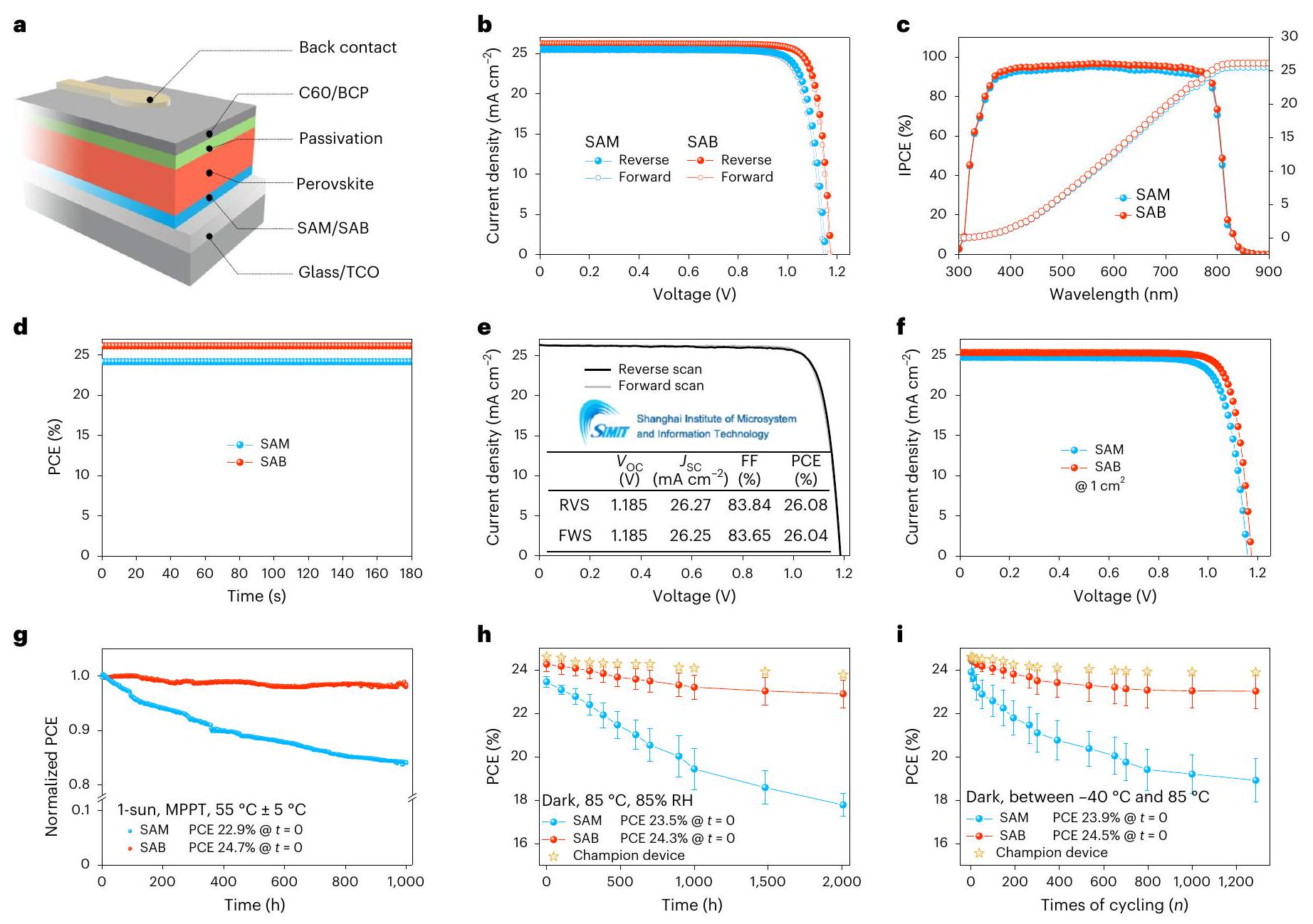
قمنا بتصنيع خلايا شمسية من نوع PSC باستخدام تكوين جهاز مقلوب: ITO-SAM أو SAB-بيروفسكايت-فوليرين )/بايثوكوبروين (BCP)/فضة (شكل 4أ). الشكل 4ب يوضح التيار-الجهد ( ) خصائص أجهزة SAM و SAB ذات الأداء الأعلى، المقاسة في كلا اتجاهي المسح الأمامي والعكسي. أظهرت جهاز SAB الرائد كفاءة تحويل الطاقة (PCE) قدرها مع جهد دائرة مفتوحة ( ) من 1.174 فولت، تيار قصر ( ) من وعامل ملء (FF) منمن المقدمةمسح، يظهر عدم وجود هيسترسيس في الأداء. هذا يمثل تحسينات على PCEs لـ (مسح عكسي) و (مسح أمامي) لجهاز البطل SAM (الشكل 4ب). لاحظنا أن قيم منتتناسب المباريات مع المتكاملالمستمدة من قياسات كفاءة الفوتون إلى التيار (IPCE): لجهاز SAM و لجهاز SAB (الشكل 4c)؛ علاوة على ذلك، تتوافق قيم كفاءة تحويل الطاقة (PCE) مع تلك الناتجة من قياسات خرج الطاقة الثابتة (SPO) (الشكل 4d). متوسط كفاءة تحويل الطاقة هو تم تسجيله ضمن مجموعة من 20 جهاز SAB، متجاوزًا متوسط كفاءة تحويل الطاقة البالغ 24.1% الذي تم الحصول عليه في 20 جهاز SAM، مع تحسينات في جميع معلمات الخلايا الشمسية (الشكل التكميلي 41 والجداول التكملية 1 و2).
أرسلنا جهاز SAB واحد إلى خدمة الاعتماد الوطنية الصينية، وهي مؤسسة معتمدة من طرف ثالث للتصديق المستقل، والتي قدمت PCE بنسبة 26.08%، مع 1.185 فولت،من و FF من ، مما يضعه بين أكثر خلايا الطاقة الشمسية كفاءة حتى الآن (الشكل 4e والشكل التكميلي 42). استراتيجية SAB فعالة للأجهزة ذات النطاق الأكبر؛ لقد حققنا كفاءة تحويل الطاقة تبلغلـ PSCs ذات مساحة نشطة من، مقارنةً بـاستنادًا إلى نهج SAM (الشكل 4f). عند تطبيقه على SAMs من حمض الفوسفونيك بخلاف 2PACz، فإنه أيضًا حسّن أداء PSC (الأشكال التكميلية 43، 44). علاوة على ذلك، قمنا بتصنيع PSCs ثلاثية الهاليد بفرقة نطاق واسعة تبلغ 1.68 eV على ركائز ITO-SAB، محققين كفاءة تحويل قصوى تصل إلى-مناسب لتطبيقات التوازي مع السيليكون (الشكل التوضيحي 45).
تم تقييم استقرار خلايا الطاقة الشمسية العضوية وفقًا لقمة الاستقرار في الخلايا الشمسية العضوية الدولية (ISOS) وبروتوكولات IEC 61215:2021 ذات الصلة بالصناعة. لم يُلاحظ أي تدهور في الأداء لأجهزة SAM وSAB (مع كفاءات تحويل أولية لـ و على التوالي) عند تخزينها تحت النيتروجين في ظروف مظلمة لمدة 140 يومًا (الشكل التوضيحي 46). لمنع تآكل القطب المعدني، تم استبدال BCP بأكسيدات القصدير المودعة بطبقات ذريةكطبقة حاجزة لظروف اختبار ISOS-L و IEC 61215:2021. أظهر جهاز SAB استقرارًا تشغيليًا أفضل تحت إضاءة مصابيح LED تعادل ضوء الشمس عند درجة حرارة الجهاز (ISOS-L-1I): خسارة نسبية دنيا في PCE قدرها تم تسجيله، على عكسفقدان لجهاز SAM، بعد 1000 ساعة من تتبع نقطة القدرة القصوى (MPPT؛ الشكل 4g).
تم إجراء تسريع الشيخوخة لخلايا الطاقة الشمسية (PSCs) عند درجات حرارة مرتفعة من و ، وفقًا لبروتوكولات ISOS-L-2I (الشكل التوضيحي التكميلي.. في ، أظهر جهاز SAM معدل تدهور كفاءة نسبي، وهو أكثر من ضعف المعدل لـ لجهاز SAB. في الوقت للاحتفاظالأداء الأولي خلال تتبع نقطة القدرة القصوى (أي، كان 192 ساعة لأجهزة SAM، بينما لأجهزة SAB، امتد بحوالي 1.7 مرة إلى 520 ساعة. طاقة التنشيط (تم تقدير ( ) لتدهور العمليات من خلال افتراض اعتماد درجة الحرارة على معدلات التدهور وفقًا لمعادلة أرهينيوس (الشكل التكميلي 47c، d). الواضح تم تحديد قيمة SAM و SAB المعتمدة على خلايا الطاقة الشمسية (PSCs) لتكون 0.46 إلكترون فولت و 0.69 إلكترون فولت، على التوالي.
الشكل 3 | خصائص واجهة الاتصال بين البيروفسكايت والجزيئات. أ، ب، أنماط GIWAXS لأفلام البيروفسكايت المودعة على SAM (أ) وSAB (ب). ج-و، طيف TRPL (ج)، طيف PL (د)، المقاومة المقاسة بواسطة TLM (هـ) والتوزيع الإحصائي لطاقة الالتصاق من أربع قياسات (و) للأجهزة التي تحتوي على واجهات بيروفسكايت-SAM أو بيروفسكايت-SAB. في هـ، تمثل الخطوط التناسبات الخطية؛ في مخطط الصندوق فيالوسائط (الخطوط المركزية)، المتوسطات (نقاط البيانات الفارغة)، الربعيات ونطاقات الربع المتداخل (الشعيرات) موضحة؛فييمثل قوة الحمل. g، h، صور SEM لأسطح البيروفسكايت المدفونة التي تم فصلها من الاتصالات الجزيئية بعد اختبارات الدورة الحرارية (على SAM (g) و On SAB (h)). i,j، مخططات فرق كثافة الإلكترون لواجهة البيروفسكايت/2PACz SAM في وضع الحافة (i) وواجهة البيروفسكايت/جزء TPA في وضع الوجه من SAB (j)، تم تصورها باستخدام برنامج VESTA للتحليل الإلكتروني والهيكلي. ترميز الألوان للذرات: Pb (رمادي)، I (بنفسجي)، C (بني)، N (فضي رمادي) وH (أبيض). Aالتكرارية مع معلمات الشبكة المحسّنة لـتم استخدامه فيطائرة.
وبالتالي، قمنا باستنتاجفيأن تكون تقريبًالـ SAM ولأجهزة SAB.
ثم أجرينا اختبارات الحرارة الرطبة والدورات الحرارية بناءً على بروتوكولات IEC 61215:2021. لتقليل دخول الرطوبة، تم تغليف خلايا الطاقة الشمسية باستخدام تعبئة زجاجية إلى زجاجية، مع مطاط بوتيل مخلوط. مع مادة التجفيف زيولايت كختم للحواف، مدعومًا بختم إيبوكسي معالج بالأشعة فوق البنفسجية (الشكل التكميلي 48). تم مراقبة أداء الجهاز بشكل دوري خلال عملية الشيخوخة المعجلة. بالنسبة لنهج SAB، تم الإشارة إلى الاستقرار الحراري من خلال احتفاظ سبعة أجهزة بمتوسط 94% من كفاءتها الأولية (بمتوسط 24.3%) بعد 2000 ساعة من
الشكل 4 | أداء الخلايا الشمسية الكهروضوئية واستقرارها. أ، رسم توضيحي تخطيطي للخلايا الشمسية المعكوسة. ب،المنحنيات الخاصة بخلايا الطاقة الشمسية المعكوسة البطل بناءً على واجهة SAM وSAB. ج، د، طيف IPCE (ج) وSPO (د) لخلايا الطاقة الشمسية المعتمدة على واجهات SAM وSAB. هـ، الاتجاه الأمامي والعكسينتائج الفحص التي تم اختبارها في معهد شنغهاي للأنظمة الدقيقة وتكنولوجيا المعلومات (SIMIT). منحنيات I-V عندمنطقة الجهاز النشطة لخلية الطاقة الشمسية القائمة على واجهات SAM وSAB.-i، تطور PCE للخلية الشمسية القائمة على واجهة SAM وSAB تحت 1-sun MPPT وفقًا لبروتوكول ISOS-L-1 (g)، تحت ظروف مظلمة ووفقًا لبروتوكول ISOS-D-3 (h)، وتحت الظلام، يتم التدوير الحراري بين و وفقًا لبروتوكول ISOS-T-3 (ط). البيانات في و تُعرض كقيم متوسطةس.د. PCEs في و تمثل القيمة المتوسطة من سبعة أجهزة لكل حالة. تم الإشارة إلى قيم الكفاءة الأولية في الإطار.، ومتوسطات PCE الأولية مذكورة في الإطارات المرفقة بـ و أشرطة الخطأ في و تعكس الانحراف المعياري بين سبعة أجهزة. اختبار الحرارة الرطبة في و RH (الشكل 4 ح). من الجدير بالذكر أن أفضل جهاز SAB أظهر فقدان نسبي في كفاءة تحويل الطاقة أقل من فوق ، وهو ما يتماشى مع معيار الصناعة لـخسارة تزيد عن 1000 ساعة للألواح الشمسية السيليكونية. بالمقابل، أظهرت خلايا الطاقة الشمسية ذات البنية الهيكلية (SAM PSCs) انخفاضًا في الأداء المتوسط (بين سبعة أجهزة) إلىخلال فترة اختبار الحرارة الرطبة.
اختبارات الدورة الحرارية اتبعت نفس الاتجاه: متوسط كفاءة تحويل الطاقة لسبعة أجهزة SAB انخفض إلىمن قيمته الأوليةبعد 1,288 دورة بين و جهاز البطل تحت اختبارات الدورة الحرارية حافظ علىكفاءتها الأولية، متجاوزةً متطلبات IEC 61215 لـانخفاض بعد 200 دورة (الشكل 4i). بالمقابل، حافظت سبعة أجهزة SAM على متوسطأداءهم الأولي خلال نفس فترات الدورات. أظهرت خصائص الإضاءة الكهروضوئية أن أجهزة SAB كانت لديها مقاومة أعلى لإعادة التركيب غير الإشعاعي بعد 200 دورة حرارية، مع كفاءة كمية خارجية لـعند تيار مطبق قدره، مقارنةً بـلأجهزة SAM خلال نفس الفترة (الشكل التوضيحي 49). تؤكد هذه النتائج الاستقرار الحراري والميكانيكي الحراري الممتاز لواجهات SAB وSAB -perovskite.
للمقارنة، قمنا بدراسة جزيء نموذج لتشكيل طبقات ثنائية، وهو حمض الفوسفونيك 2-(4-(ثنائي(4-ميثوكسي فينيل)أمين)فينيل)-1-سيانو فينيل) (MPA-CPA)، الذي يعتمد على التفاعلات غير التساهمية بين الطبقات. التفاعلاتتم اختبار عقود الخدمة العامة المعتمدة على MPA-CPA تحت MPPT في وإضاءة LED تعادل 1 شمس، والتي أظهرت لمدة 210 ساعة (أقصر بـ 2.5 مرة من تلك الخاصة بأجهزة SAB) (الشكل التكميلي 50a). عند تعرضها لدورات حرارية بين و ، أظهرت أجهزة MPA-CPA أكثر منتدهور في الأداء بعد 150 دورة فقط، مما أدى إلى أداء أقل بكثير مقارنة بأجهزة SAB (الشكل التكميلي 50b). لقد قمنا بتلخيص خلايا الطاقة الشمسية الموصوفة التي خضعت لاختبارات الحرارة الرطبة والدورات الحرارية (الشكل التكميلي 51).مظهراً استقراراً ممتازاً لأجهزتنا المغلفة من نوع SAB بين الفئتين، تم تحقيقه مع كفاءة تحويل الطاقة تزيد عن 24% (الجدولان التكميليان 3 و4).
الاستنتاجات
أظهر هذا العمل أن SAB المرتبط تساهميًا هو نوع جديد من جهات الاتصال الجزيئية الانتقائية للثقوب في خلايا الطاقة الشمسية. تتشكل الهياكل ثنائية الطبقات من خلال ألكلة فريدل-كرافتس على الركيزة، حيث تربط وحدات TPA مع SAM حمض الفوسفونيك عبر جسر ميثيلين. إن نهج كيمياء السطح متعدد الاستخدامات، ويتوافق مع مجموعة من الجزيئات التي تشكل SAM وعوامل الألكلة. الشبكة المتقاطعة الناتجة تحمي SABs من التسامي الحراري، مما يقاوم التدهور عندلمدة 200 ساعة. علاوة على ذلك، تظهر وحدات TPA اتصالات لاصقة مع أسطح البيروفسكايت، مما يقلل من التدهور الحراري الميكانيكي في الطبقات المدفونة. واجهة. حققنا PCE معتمد يزيد عنلـ PSCs المقلوبة، مع أقل منفقدان الكفاءة بعدتعرض للحرارة الرطبة ( و ) و فقدان الكفاءة بعد 1200 دورة حرارية بين و لأجهزة استقرار الأبطال المغلقة. تعزز الاتصالات الجزيئية متعددة الطبقات التي تستفيد من الروابط التساهمية بين الطبقات مقاومة خلايا الطاقة الشمسية للضغوط المتعلقة بدرجات الحرارة.
طرق
المواد
المذيبات اللامائية بما في ذلك CB،تم شراء ثنائي ميثيل الفورماميد، DMSO والإيزوبروبانول من سيغما-ألدريتش. تم شراء الإيثانول اللامائي من ألالدين. تم شراء يوديد الرصاص ( ), BCP ( تم شراء بروميد الجوانيدينيوم و 2PACz (>98%) من TCI. يوديد الفوراميدينيوم (تم شراء ( ) من شركة جريت سيل سولار. بروميد الميثيل أمونيوم (99.5%)، يوديد الميثيل أمونيوم (99.5%)، كلوريد الميثيل أمونيوم (99.5%)، يوديد السيزيوم (CsI، 99.999%) وتم شراءها من تكنولوجيا الضوء البوليمري في شيآن. تم شراء 1،2-ثنائي كلوروبنزين، رباعي بوتيل الأمونيوم هكسافلورو فوسفات وغيرها من المذيبات والمواد الكيميائية إذا لم يتم ذكرها أعلاه من أدماس الصين. الزجاجات الموصلية، FTO ( لكل متر مربع)، ITO ( لكل متر مربع) وورقة الطلاء المضاد للانعكاس تم شراؤها من شركة سوزو شانغ يانغ لتكنولوجيا الطاقة الشمسية.
تركيب TATPA
إلى محلول من-نيتريلوترينزيلدهيدفي أنهدريد الأسيتيك-دي إيزوبروبيل إيثيل أمينتم إضافته ببطء في حمام مائي مثلج تحتالحماية. ثم تمت إزالة حمام الماء المثلج، وتم تحريك خليط التفاعل فيلمدة ساعتين إضافيتين. عند الانتهاء من التفاعل، تم تبريد المزيج إلى درجة حرارة الغرفة قبل أن يتم صبه ببطء في مزيج من ماء الثلج والأسيتات الإيثيلي. تم تحريك المزيج لمدة 15 دقيقة قبل إضافة حمض الهيدروكلوريك ( ) وهيدروكسيد الصوديوم ( ) تمت إضافتها لاحقًا. تم استخراج الطبقة العضوية عدة مرات وتجفيفها بمادة كبريتات الصوديوم اللامائية. تم تنقية المنتج الخام بواسطة كروماتوغرافيا العمود على هلام السيليكا (أسيتات الإيثيل: إيثرثم تمت إزالة المذيب بواسطة التبخر الدوار للحصول على المنتج النهائي كصلب أبيض.الرنين المغناطيسي النووي، الرنين المغناطيسي النووي ، DMSO-d6 ، TMS و 21.22.
تصنيع الأجهزة
تم تحضير محلول سلفي بيروفسكايت باستخدام الإجراء التالي: 9.0 ملغ من بروميد الميثيل أمونيوم، 23.9 ملغ من سيزيم يوديد، 22.2 ملغ من يوديد الميثيل أمونيوم، 292.3 ملغ من يوديد الفورماميدينيوم،منوتم إذابة 10.8 ملغ من كلوريد الميثيل أمونيوم في 1.3 مل منمحلول مختلط من ثنائي ميثيل الفورماميد و DMSO (نسبة الحجم: 4:1) وتم التحريك لمدة ساعة. تستخدم خلايا الشمسية المعكوسة بنية جهاز من ITO-HSC-بيروفسكايت--BCP-Ag. تم تنظيف زجاج ITO أو FTO من تقنية ShangYang بشكل متسلسل باستخدام محلول مائي يحتوي على 2% من المنظفات، وماء منزوع الأيونات، والأسيتون، والإيثانول، مع استخدام الموجات فوق الصوتية لمدة 20 دقيقة لكل مذيب. بعد التجفيف باستخدام تدفق النيتروجين، تم تطبيق الأشعة فوق البنفسجية والأوزون لمزيد من التنظيف. تم إجراء الإجراءات التالية في صندوق قفازات مملوء بمحتوى أكسجين أقل من 1 جزء في المليون ومحتوى ماء أقل من 0.1 جزء في المليون. تم إذابة 2PACz SAM النقي في الإيثانول عندوتم طلاءه بالدوران مباشرة على سطح أكسيد الموصل الشفاف (TCO) الذي تم تنظيفه مسبقًا، ثم تم تسخينه عند لمدة 10 دقائق. تم تحضير SAB عن طريق ترسيب 2PACz و TATPA بشكل متتابع. تم ترسيب 2PACz أولاً على TCO، تلاه طلاء دوار لـ TATPA فوق 2PACz في في الإيثانول. تم تسخين الطبقة الثنائية عندلمدة 10 دقائق. تم تبريد خلايا الشمسية عالية الكفاءة إلى درجة حرارة الغرفة قبل ترسيب طبقة البيروفسكايت. ثم تم ترسيب محلول سلف البيروفسكايت على ركيزة ITO-HSC التي تم تحضيرها حديثًا باستخدام طريقة الطلاء الدوراني ذات الخطوتين: الخطوة الأولى تمت بسرعة 1000 دورة في الدقيقة مع معدل تسارع لمدة 10 ثوانٍ والخطوة الثانية عند 5000 دورة في الدقيقة مع معدل تسارع لمدة 30 ثانية. في الثانية الخامسة عشر، تم تطبيق CB. بعد الطلاء بالطرد المركزي، تم تسخين الركيزة. لمدة 50 دقيقة. وُجد أن محتوى الكلور قد انخفض خلال التلدين الحراري، مما خفض عنصر الكلور المتبقي إلى مستويات أقل من حدود الكشف لتحليل الأشعة السينية المشتتة بالطاقة وتحليل XPS (الأشكال التكميلية 52 و 53). طبقة رقيقة من التمرير باستخدام بروميد الجوانيدينيوم في الإيثانول ( ) تم تطبيقه على سطح طبقة البيروفسكايت. و BCP تم إيداعها بشكل متسلسل بمعدلات و “، على التوالي. أخيرًا، تم تبخير 100 نانومتر من الفضة حراريًا باستخدام قناع ظل.تُصنع خلايا شمسية مقلوبة باستخدام نهج مشابه، على الرغم من أن التصاميم في تخطيط الأقطاب والأقنعة الظلية مختلفة. نلاحظ أن استراتيجية SAB فعالة لكل من الركائز FTO وITO.
توصيف خلايا الشمسية
التم قياس خصائص خلايا الشمس باستخدام مقياس مصدر كيثلي 2400 تحت إضاءة محاكي الشمس (نيو بورت، فئة AAA) عند شدة ضوء، الذي يتم معايرته مع خلية شمسية مرجعية (نيو بورت). يتم تحديد المنطقة النشطة بواسطة قناع ظل ( أو تم تسجيل طيف الكفاءة الكمية الخارجية باستخدام نظام تجاري (Arkeo-Ariadne، Cicci Research) يعتمد على مصدر ضوء زينون بقوة 300 واط ومقياس تدرج هولوجرافي (Cornerstone، Newport). تم قياس خرج الطاقة المستقر بواسطة مقاييس مصدر Keithley 2400 تحت نفس محاكي الشمس.
قياسات استقرار خلايا الشمس
لقياسات الاستقرار التشغيلي على المدى الطويل، تم وضع الخلايا غير المغلفة في محطة تتبع الاستقرار محلية الصنع محمية تحتالجو. كان مصدر الإضاءة LED ضوء أبيض (تيانجين ماتو، درجة A) مع شدة تم معايرتها لتتناسب مع حالة الشمس الواحدة. تم الاحتفاظ بالأجهزة في و تم تسجيل نقطة القدرة القصوى كل ساعة، وتم الحفاظ على خلايا الشمس عند جهد نقطة القدرة القصوى خلال هذه الفترة. من أجل استقرار التخزين على المدى الطويل، يتم تخزين الخلايا غير المغلفة فيصندوق قفازات مملوء بالأكسجين ومحتويات الماء أقل من 1 جزء في المليون و0.1 جزء في المليون، على التوالي. نلاحظ أنه من المهم عدم تخزين الأجهزة في نفس صندوق القفازات لتصنيع الأجهزة، حيث إن بخار المذيب سيسبب تدهورًا شديدًا في أداء الجهاز. تم قياس استقرار الحرارة الرطبة واستقرار دورة الحرارة باستخدام صندوق تحكم في درجة الحرارة والرطوبة قابل للبرمجة من آلة جينغ يو. تم وضع الأجهزة بين زجاجتين، حيث تم استخدام الكوارتز في جانب الإضاءة. تم ملء واجهة الجهاز-الكوارتز وعلاجها باستخدام لاصق إبوكسي شفاف لتجنب الانعكاس الإضافي في الفجوة الهوائية. تم الاتصال بين الجهاز وزجاج الاتصال الخلفي بشريحة من معدن الإنديوم التي تم تقطيعها إلى حجم مشابه لحجم الوسادة. تم تغليف الجهاز بعناية مرتين بشكل أولي باستخدام لاصق بولي إيزوبوتيل ثم لاصق معالج بالأشعة فوق البنفسجية.تظهر صورة لجهاز نهائي مغلف في الشكل التوضيحي 48. نلاحظ أن بروتوكول IEC 61215:2021 مصمم لوحدات الطاقة الشمسية المصنوعة من السيليكون ويتضمن سلسلة من الاختبارات تتجاوز الحرارة الرطبة والدورات الحرارية، بما في ذلك اختبار الحمل الميكانيكي الثابت واختبارات البَرَد. من المتوقع أن يتم تطوير بروتوكولات اختبار محددة لخلايا البيروفيسكايت؛ ومع ذلك، لا يزال بروتوكول IEC 61215:2021 مستخدمًا على نطاق واسع من قبل مجتمع البيروفيسكايت لتقييم ومقارنة استقرار خلايا الطاقة الشمسية.
قياسات XPS
تم تسجيل طيف XPS باستخدام نظام Thermo Fisher Scientific ESCALAB Xi+ معمحلل نصف كروي ذو تركيز مزدوج. النظام مزود بكاشف مكون من 128 قناة و XPS أحادي اللون بنقطة صغيرة. تم استخدام مصدر AlKα للتحفيز وتم استخدام طاقة مرور تبلغ 50 eV للحصول على بيانات XPS. تم تحليل جميع البيانات باستخدام برنامج Thermo Avantage. بالنسبة لتحضير عينة XPS، يتبع ترسيب طبقة HSC وطبقة البيروفسكايت النشطة ضوئيًا نفس البروتوكول كما هو تصنيع PSC مقلوب، كما هو موضح في قسم تصنيع الجهاز. تم زيادة تركيز السلف.لكل من 2PACz و TATPA لتحسين نسبة الإشارة إلى الضوضاء.
قياسات الرنين المغناطيسي النووي للبروتون
تم إجراء التحليل الطيفي بالرنين المغناطيسي النووي باستخدام جهاز طيفي من نوع Bruker 400 MHz ASCEND ADVANCE III HD. لتحضير العينة، قمنا في البداية بتحضير محلول مختلط يحتوي على2PACz وتم تحضير TATPA وصب فيلم رقيق من هذا المزيج. تم زيادة التركيز عشرة أضعاف للحصول على عينة كافية لاختبار NMR. تم تسخين الفيلم عندلمدة 10 دقائق ثم تم كشطه من الركيزة، مما أسفر عن مادة صلبة ذات لون أخضر. كان اللون الأخضر ناتجًا بشكل أساسي عن المرحلة الوسيطة الكربوكاتيون غير المتفاعلة (الشكل التوضيحي التكميلي 8).. هذا الصلب غير قابل للذوبان في CB المؤشر و DMSO. وبالتالي، استخدمنا تفاعل نموذج يحتوي على مكونات مختلطة من NECz و TATPA و 2PACz، كما هو موضح في النص الرئيسي ومبين في الشكل 1c.
حسابات DFT
تم إجراء حسابات هيكل الإلكترونيات المعتمدة على الاستقطاب الدوراني باستخدام نهج مجموعة الأساس الموجي المسطح كما هو مطبق في حزمة المحاكاة من فيينا (VASP).تم استخدام طريقة الموجة المعززة بواسطة البروجيكتور لتمثيل تفاعلات الإلكترونات مع نواة الأيون.تم تمثيل الإلكترونات التكافؤية باستخدام مجموعة أساس الموجة المسطحة مع حد طاقة يبلغ 450 إلكترون فولت. تم وصف التبادل الإلكتروني والترابط باستخدام دالة بيردو-بورك-إرنزرهوف.تم استخدام طريقة DFT-D3 لتصحيح تفاعل فان der Waals.. أتم استخدام فراغ مفرغ لتجنب التفاعلات بين الألواح السطحية.شبكات النقاط لـ و تم استخدامها لأخذ عينات من منطقة بريلوانالسطح وجزيئات معزولة أخرىتم تحديد معايير التقارب للبنية الإلكترونية الذاتية الاتساق والهندسة إلى و ، على التوالي. طاقات الربط ( ) تم حسابها بواسطة
أين و تمثل الطاقات الكلية للنظام المرتبط،السطح والمواد الممتصة، على التوالي.
الاختبار الميكانيكي
اختبار طاقة الالتصاق يتبع نفس الإجراء كما تم الإبلاغ عنه سابقًاباختصار، اعتمدت عينات DCB هياكل من الزجاج-TCO-HSC-بيروفسكايت-بولي(mيثيل ميثاكريلات) (PMMA)-إيبوكسي-TCO-زجاج. بالنسبة لعينة التحكم، يتكون HSC من 2PACz، وللعينات المستهدفة، يتم استخدام SAB. تم إذابة PMMA (350 كيلودالتون) في CB، وتم طلاءها بالدوران على سطح طبقة البيروفسكايت وتمت معالجتها حرارياً عندلمدة 5 دقائق. ثم تم تطبيق راتنج إبوكسي هش على طبقة PMMA قبل أن يتم laminating بواسطة زجاج TCO آخر. تم إجراء DCB باستخدام الإجراء المبلغ عنه. تم ضبط معدل الإزاحة علىفي الوقت نفسه تسجيل قوة الحمل ( ) و الإزاحة ( ). طول الشق، المشار إليه بـ ، تم تقديره باستخدام
أين و تمثل عرض وموصلية يونغ للركيزة الزجاجية، على التوالي، و هو نصف سمك عينة DCB. طاقة الالتصاق، يتم إعطاؤه بواسطة
أينهو الحمل عند بداية عدم الخطية فيالمنحنى. نلاحظ أن التحميل تم تكراره خمس مرات، والمتوسطتم حساب القيم من آخر أربع تكرارات.
قياسات TLM
في تقنية TLM، المقاومة الكلية ( ) بين جهتين بطول ( ) وعرض ( ) يتم قياسه ورسمه كدالة لمسافة الاتصال . كـمع زيادة، تزداد تأثير مقاومة الورقة على قياس المقاومة الكلي. إن ملاءمة المنحنى الناتج لدالة خطية ينتج عنه خط مستقيم مع ميليمكن حساب مقاومة الورقة من هذا الميل باستخدام المعادلة التالية :
فيمقاومة الاتصاليمكن حسابه باستخدام
قياسات السيرة الذاتية
تم إجراء قياسات السعة باستخدام تكوين ثلاثي الأقطاب مع جهاز قياس الجهد (DH7000C، DONGHUA). تم تحضير الأقطاب العاملة، إما زجاجات TCO المغطاة بـ SAM أو SAB، وفقًا لنفس البروتوكول المستخدم في تصنيع الجهاز. تم استخدام سلك من البلاتين كقطب مضاد، وسلك فضي كقطب مرجعي. لفهم عملية إزالة SAM أو SAB عند واجهات TCO-البيروفسكايت خلال اختبارات الدورة الحرارية، تم تقشير طبقة البيروفسكايت باستخدام إجراء معتمد.تمت إزالة خلايا الشمسية المعكوسة أولاً من تغليفها. بعد ذلك، تم تقشير الاتصال المعدني بلطف باستخدام شريط سكوتش. ثم تم طلاء طبقة رقيقة من PMMA على سطح البيروفسكايت.-طبقة BCP. تم تطبيق قطرة من الغراء القابل للتصلب بالأشعة فوق البنفسجية (ThreeBond 3035B) على سطح PMMA، وتم لصق ورقة مرنة من بولي إيثيلين تيرفثالات على الغراء. تم معالجة الكومة تحت ضوء الأشعة فوق البنفسجية (256 نانومتر)، مما سهل تقشير كومة بولي إيثيلين تيرفثالات-بيروفسكايت وترك الركيزة تكشف عن HSC، إما 2PACz SAM أو SAB. تم قياس الكثافة السطحية لـ 2PACz و2PACz-TATPA في 1،2-ثنائي كلوروبنزين مع 0.1 م TBA.الإلكتروليت. تم الإشارة إلى جميع الجهود مقابل زوج الفيروسيوم الأحمر، الذي يعمل كمعيار داخلي. تم تحديد التغطية الفعالة لـ SAM أو SAB على سطح ITO من خلال ميل الاعتماد الخطي لشدة الذروة التأكسدية مقابل معدل المسح.
أين هو تيار الذروة الأكسدي (A)، هو معدل مسح الجهد هو عدد الإلكترونات المنقولة، ثابت فاراداي هو ثابت الغاز العالمي هو هو درجة الحرارة ( ك )، ثابت أفوجادرو هو ، هو مساحة القطب الكهربائي وجزيئاتهي كثافة السطح التي يمكن الحصول عليها من خلال حساب ميل ضد .
خصائص أخرى
تم إجراء قياس ATR-FTIR باستخدام جهاز Bruker VERTEX70، وتم مسح العينات في النطاق الطيفي لـتم قياس مطيافية الكتلة عالية الدقة على جهاز Thermo Scientific Q Exactive مع مصادر أيونية لتأين الكيمياء تحت الضغط الجوي. تم إجراء تحليلات كيميائية سطحية باستخدام جهاز PHI nano TOF 3+ (ULVAC-PHI)، المزود ببندقية أيونية من المعدن السائل البزموت كحزمة أولية وبندقية أيونية من الغاز الكتلي (GCIB)-Ar-Cs كمصدر للتبخير. تم الحصول على بيانات TOF-SIMS بواسطةتم تشغيل مصدر الأيونات النابضة في وضع الدقة العالية (وضع التجميع)، وتم قياس التيار المستمر لمصدر البزموت بمقدار 9.3 نانو أمبير. تم جمع طيف الأيونات الموجبة في 100 إطار.تمت معالجة البيانات باستخدام برنامج تقليل بيانات TOF-SIMS (TOF-DR). تم قياس KPFM باستخدام مجهر القوة الذرية Asylum Cypher S (أكسفورد إنسترومنتس) مع ASYELEC المطلية بطبقة من التيتانيوم والإيريديوم ومجهر القوة الذرية Nanosurf AG، Flex-Mount. كانت سعة الإثارة 4 فولت، وتم ضبط معدل المسح على 0.25 هرتز. تم إجراء GIWAXS في خطي الأشعة BL02U2 و BL17B1.
مرفق إشعاع السنكروترون في شنغهاي (SSRF) باستخدام طاقة الأشعة السينية 10 كيلو إلكترون فولت. تم الحصول على صور ثنائية الأبعاد بواسطة كاشف PLATUS 2M مثبت عموديًا على مسافةمن العينة بزاوية سقوط راعويوزمن التعرض 20 ثانية. تم الحصول على صور SEM عالية الدقة باستخدام GeminiSEM 500 بجهد تسريع قدره 1.5 كيلو فولت. تم قياس طيف TRPL باستخدام M-X355L (Orient KOJI) بتردد 10 كيلو هرتز ومدة 350 بيكوثانية لمصدر الضوء المستخدم في القياس. كانت كثافة القدرة المطبقة هي، وكانت شدة الإثارة هي و .
توفر البيانات
جميع البيانات التي تم توليدها أو تحليلها خلال هذه الدراسة مدرجة في المقالة ومعلوماتها التكميلية وبيانات المصدر. يتم توفير بيانات المصدر مع هذه الورقة.
References
Kojima, A., Teshima, K., Shirai, Y. & Miyasaka, T. Organometal halide perovskites as visible-light sensitizers for photovoltaic cells. J. Am. Chem. Soc. 131, 6050-6051 (2009).
Tan, S. et al. Stability-limiting heterointerfaces of perovskite photovoltaics. Nature 605, 268-273 (2022).
McMeekin, D. et al. Intermediate-phase engineering via dimethylammonium cation additive for stable perovskite solar cells. Nat. Mater. 22, 73-83 (2023).
You, S. et al. Radical polymeric p-doping and grain modulation for stable, efficient perovskite solar modules. Science 379, 288-294 (2023).
Domanski, K., Alharbi, E. A., Hagfeldt, A., Gratzel, M. & Tress, W. Systematic investigation of the impact of operation conditions on the degradation behaviour of perovskite solar cells. Nat. Energy 3, 61-67 (2018).
Li, Z. et al. Stabilized hole-selective layer for high-performance inverted p-i-n perovskite solar cells. Science 382, 284-289 (2023).
Azmi, R. et al. Damp heat-stable perovskite solar cells with tailored-dimensionality 2D/3D heterojunctions. Science 376, 73-77 (2022).
Jiang, Q. et al. Surface reaction for efficient and stable inverted perovskite solar cells. Nature 611, 278-283 (2022).
Li, G. et al. Highly efficient p-i-n perovskite solar cells that endure temperature variations. Science 379, 399-403 (2023).
Dai, Z. et al. Interfacial toughening with self-assembled monolayers enhances perovskite solar cell reliability. Science 372, 618-622 (2021).
IEC 61215-1:2021 Terrestrial Photovoltaic (PV) Modules-Design Qualification and Type Approval-Part 1: Test Requirements 2nd edn (International Electrotechnical Commission, 2021).
Jiang, Q. et al. Towards linking lab and field lifetimes of perovskite solar cells. Nature 623, 313-318 (2023).
Mei, A. et al. Stabilizing perovskite solar cells to IEC61215:2016 standards with over 9,000-h operational tracking. Joule 4, 2646-2660 (2020).
Khenkin, M. V. et al. Consensus statement for stability assessment and reporting for perovskite photovoltaics based on ISOS procedures. Nat. Energy 5, 35-49 (2020).
Al-Ashouri, A. et al. Conformal monolayer contacts with lossless interfaces for perovskite single junction and monolithic tandem solar cells. Energy Environ. Sci. 12, 3356-3369 (2019).
Peng, W. et al. Reducing nonradiative recombination in perovskite solar cells with a porous insulator contact. Science 379, 683-690 (2023).
Park, S. M. et al. Low-loss contacts on textured substrates for inverted perovskite solar cells. Nature 624, 289-294 (2023).
Tang, H. et al. Reinforcing self-assembly of hole transport molecules for stable inverted perovskite solar cells. Science 383, 1236-1240 (2024).
Yu, S. et al. Homogenized nanoparticles for improved hole transport in inverted perovskite solar cells. Science 382, 1399-1404 (2023).
Hotchkiss, P. J. et al. The modification ofindium tin oxide with phosphonic acids: mechanism of binding, tuning of surface properties, and potential for use in organic electronic applications. Acc. Chem. Res. 45, 337-346 (2012).
Zhang, S. et al. Minimizing buried interfacial defects for efficient inverted perovskite solar cells. Science 380, 404-409 (2023).
Zheng, X. et al. Co-deposition of hole-selective contact and absorber for improving the processability of perovskite solar cells. Nat. Energy 8, 462-472 (2023).
Turren Cruz, S., Hagfeldt, A. & Saliba, M. Methylammonium-free, high-performance, and stable perovskite solar cells on a planar architecture. Science 362, 449-453 (2018).
Chen, R. et al. Reduction of bulk and surface defects in inverted methylammonium- and bromide-free formamidinium perovskite solar cells. Nat. Energy 8, 839-849 (2023).
Zhao, Y. et al. Discovery of temperature-induced stability reversal in perovskites using high-throughput robotic learning. Nat. Commun. 12, 2191 (2021).
Li, X. et al. Constructing heterojunctions by surface sulfidation for efficient inverted perovskite solar cells. Science 375, 434-437 (2022).
He, R. et al. Improving interface quality for all-perovskite tandem solar cells. Nature 618, 80-86 (2023).
Li, Z. et al. Organometallic-functionalized interfaces for highly efficient inverted perovskite solar cells. Science 376, 416-420 (2022).
Li, T. et al. Inorganic wide-bandgap perovskite subcells with dipole bridge for all-perovskite tandems. Nat. Energy 8, 610-620 (2023).
Tan, Q. et al. Inverted perovskite solar cells using dimethylacridine-based dopants. Nature 620, 545-551(2023).
Woodruff, M. A. & Hutmacher, D. W. The return of a forgotten polymer-polycaprolactone in the 21st century. Prog. Polym. Sci. 35, 1217-1256 (2010).
Guzmán, E., Rubio, R. G. & Ortega, F. A closer physico-chemical look to the layer-by-layer electrostatic self-assembly of polyelectrolyte multilayers. Adv. Colloid Interface Sci. 282, 102197 (2020).
Zhang, X., Chen, H. & Zhang, H. Layer-by-layer assembly: from conventional to unconventional methods. Chem. Commun. 14, 1395-1405 (2007).
Pitaro, M. et al. Tuning the surface energy of hole transport layers based on carbazole self-assembled monolayers for highly efficient perovskite solar cells. Adv. Funct. Mater. 34, 2306571 (2023).
Yao, Y. et al. Organic hole-transport layers for efficient, stable, and scalable inverted perovskite solar cells. Adv. Mater. 34, 2203794 (2022).
Aukland, M. H., Šiaučiulis, M., West, A., Perry, G. & Procter, D. Metal-free photoredox-catalysed formal C-H/C-H coupling of arenes enabled by interrupted Pummerer activation. Nat. Catal. 3, 163-169 (2020).
Saber, A. F., Sharma, S., Lee, J., El-Mahdy, A. F. M. & Kuo, S. Carbazole-conjugated microporous polymers from SuzukiMiyaura coupling for supercapacitors. Polymer 254, 125070 (2022).
Wang, Y.-X. & Leung, M.-K. 4,4′,4′-Tris(acetoxymethylene) triphenylamine: an efficient photoacid promoted chemical cross-linker for polyvinylcarbozole and its applications for photolithographic hole-transport materials. Macromolecules 44, 8771-8779 (2011).
Topa, M. et al. One-component cationic photoinitiators based on coumarin scaffold iodonium salts as highly sensitive photoacid generators for 3D printing IPN photopolymers under visible LED sources. Polym. Chem. 11, 5261-5278(2020).
Memon, W. A. et al. Precise control of crystal orientation of conjugated molecule enables anisotropic charge transport properties. Adv. Funct. Mater. 32, 2110080 (2022).
Ogle, J., Powell, D., Amerling, E., Smilgies, D.-M. & Whittaker-Brooks, L. Quantifying multiple crystallite orientations and crystal heterogeneities in complex thin film materials. CrystEngComm 21, 5707-5720 (2019).
Fuchs, F., Caffy, F., Demadrille, R., Mélin, T. & Grévin, B. High-resolution Kelvin probe force microscopy imaging of interface dipoles and photogenerated charges in organic donoracceptor photovoltaic blends. ACS Nano 10, 739-746 (2016).
Peng, S. et al. Direct detection of local electric polarization in the interfacial region in ferroelectric polymer nanocomposites. Adv. Mater. 31, 1807722 (2019).
Liu, M. et al. Compact hole-selective self-assembled monolayers enabled by disassembling micelles in solution for efficient perovskite solar cells. Adv. Mater. 35, 2304415 (2023).
Mirle, C. R., Raja, M., Vasudevarao, P., Sankararaman, S. & Kothandaraman, R. Functionalised carbazole as a cathode for high voltage non-aqueous organic redox flow batteries. N. J. Chem. 44, 14401-14410 (2020).
Ciobanu, M. et al. High contrast hybrid electrochromic film based on cross-linked phosphonated triarylamine on mesoporous antimony doped tin oxide. Sol. Energ. Mat. Sol. C 203, 110186 (2019).
Chen, L. et al. Exploring the influence of the contact resistance on perovskite phototransistors. Appl. Phys. Lett. 124, 162202 (2024).
Liang, J. et al. Origins and influences of metallic lead in perovskite solar cells. Joule 6, 816-833 (2022).
Xu, J. et al. Triple-halide wide-band gap perovskites with suppressed phase segregation for efficient tandems. Science 367, 1097-1104 (2020).
Mariotti, S. et al. Interface engineering for high-performance, triple-halide perovskite-silicon tandem solar cells. Science 381, 63-69 (2023).
Zhao, X. et al. Accelerated aging of all-inorganic, interfacestabilized perovskite solar cells. Science 377, 307-310 (2022).
Hao, M. et al. Flattening grain-boundary grooves for perovskite solar cells with high optomechanical reliability. Adv. Mater. 35, 2211155 (2023).
Ahmad, T., Dasgupta, S., Almosni, S., Dudkowiak, A. & Wojciechowski, K. Encapsulation protocol for flexible perovskite solar cells enabling stability in accelerated aging tests. Energy Environ. Mater. 6, e12434 (2023).
Heo, J. H., Choi, Y. K., Koh, C. W., Woo, H. Y. & Im, S. H. Semitransparent perovskite solar cells stable under simultaneous damp heat ( ) and 1 sun light soaking. Adv. Mater. Technol. 4, 1800390 (2019).
Lin, X. et al. In situ growth of graphene on both sides of a Cu-Ni alloy electrode for perovskite solar cells with improved stability. Nat. Energy 7, 520-527(2022).
Li, H. et al. 2D/3D heterojunction engineering at the buried interface towards high-performance inverted methylammonium-free perovskite solar cells. Nat. Energy 8, 946-955 (2023).
Liang, Z. et al. Homogenizing out-of-plane cation composition in perovskite solar cells. Nature 624, 557-563 (2023).
Zhu, P. et al. Aqueous synthesis of perovskite precursors for highly efficient perovskite solar cells. Science 383, 524-531 (2024).
Gaulding, E. A. et al. Package development for reliability testing of perovskites. ACS Energy Lett. 7, 2641-2645 (2022).
Xia, C., Advincula, R. C., Baba, A. & Knoll, W. Electrochemical patterning of a polyfluorene precursor polymer from a microcontact printed ( ) monolayer. Chem. Mater. 16, 2852-2856 (2004).
Kresse, G. & Furthmüller, J. Efficiency of ab-initio total energy calculations for metals and semiconductors using a plane-wave basis set. Comput. Mater. Sci. 6, 15-50 (1996).
Kresse, G. & Joubert, D. From ultrasoft pseudopotentials to the projector augmented-wave method. Phys. Rev. B 59, 1758-1775 (1999).
Perdew, J. P., Burke, K. & Ernzerhof, M. Generalized gradient approximation made simple. Phys. Rev. Lett. 77, 3865-3868 (1996).
Grimme, S., Antony, J., Ehrlich, S. & Krieg, H. A consistent and accurate ab initio parametrization of density functional dispersion correction (DFT-D) for the 94 elements H-Pu. J. Chem. Phys. 132, 154104 (2010).
Monkhorst, H. J. & Pack, J. D. Special points for Brillouin-zone integrations. Phys. Rev. B 13, 5188-5192 (1976).
Guo, S., Gregory, G., Gabor, A. M., Schoenfeld, W. V. & Davis, K. O. Detailed investigation of TLM contact resistance measurements on crystalline silicon solar cells. Sol. Energy 151, 163-172 (2017).
Syed, A. M., Iqbal, A. K., Waheed, A. Y. & Khasan, S. K. in Conducting Polymers (ed. Faris, Y.) Ch. 5 (IntechOpen, 2016).
شكر وتقدير
تمت هذه البحث بفضل التمويل الابتدائي من جامعة شيان جياوتونغ في إطار ‘خطة دعم المواهب الشابة’ (71211223010709). وقد تم دعم العمل جزئيًا من قبل المؤسسة الوطنية للعلوم الطبيعية في الصين (GYKPO38، Y. Liu؛ 52403248، Y. Liu؛ 12175298، Y.Y؛ 22279039، X.L.). كما تم دعم هذا العمل بموجب منحة تشين تشوانغ يوان رقم QCYRCXM-2023-067. وقد تم دعم العمل من قبل البرنامج الوطني الرئيسي للبحث والتطوير في الصين (2022YFE0132400، W.M.، 2022YFB4200305، X.L.، 2024YFE0103700، X.L.). يشكر M.W. دعم أستاذية الشباب الرئاسية في جامعة سنغافورة الوطنية (A-0010046-00-00؛ A-0010046-01-00). يشكر A.H. الدعم من وكالة الطاقة السويدية (P2020-90215) ومجلس البحث السويدي (2019-05591، 2023-05244). يشكر M.G. و S.M.Z. الدعم من شركة خلايا الطاقة الشمسية غونيس بيروفيسكيت الواقعة في أضنة، تركيا. نشكر H. Qiu في شركة أورينت كوجي العلمية و D. He في مركز تحليل الأدوات في جامعة شيان جياوتونغ على المساعدة في قياس TRPL؛ و P. Zhou في مركز تحليل الأدوات في جامعة شيان جياوتونغ على تحليل NMR؛ و F. Tan على تحليل ATR-FTIR. استخدم هذا العمل خطوط الأشعة BLO1B1، BLO2U2، BL17B1، BLO6B، BL16U1 و BL19U2 في SSRF وتلقى الدعم من خلال نظام مساعدة تجارب المستخدمين في SSRF. نشكر G. Gao و N. Gao في كلية الكيمياء بجامعة شيان جياوتونغ على مساعدتهم في قياسات SEM؛ و eceshi على تحليلات XPS و UV photoelectron spectroscopy.
مساهمات المؤلفين
قام ي. ليو بتصور الفكرة وإشراف المشروع. قام ي. ليو، م. و، س. ي، إكس. ل و م. ج. بتصميم هذا المشروع. قام ب. د، س. ي، ي. لي و ي. ز. بتصنيع أجهزة الخلايا الشمسية وإجراء تحليل للأجهزة. قام ب. د بإجراء قياسات XPS و FTIR و TRPL وموصلية واستقرار وقياس CV. قامت ي. ي بإجراء قياسات وتحليل GIWAXS. قامت ي. ز بإجراء قياسات KPFM. قام ي. ليو و ي. ر. بتخليق TATPA. قامت م. ج بإجراء قياسات NMR. قام ز. س بإجراء قياسات SEM. ساعد ز. ب في تحليل GIWAXS. قام ز. د و ه. ج بإجراء قياسات TOF-SIMS. قام ي. ليو، م. و و س. ي بتحليل البيانات. كتب ي. ليو و م. و المسودة الأصلية. ساهم ي. ليو، م. و، س. ي، و. م، س. م. ز، أ. ح، ت. إ، إكس. ل و م. ج في تحرير المخطوطة. ناقش جميع المؤلفين النتائج وراجعوا المخطوطة.
المصالح المتنافسة
قد قدم Y. Liu طلب براءة اختراع استنادًا إلى المفهوم الذي تم تطويره في هذه المخطوطة. يعلن المؤلفون الآخرون عدم وجود مصالح متنافسة.
ملاحظة الناشر: تظل شركة سبرينغر ناتشر محايدة فيما يتعلق بالمطالبات القضائية في الخرائط المنشورة والانتماءات المؤسسية.
الوصول المفتوح. هذه المقالة مرخصة بموجب رخصة المشاع الإبداعي النسب-غير التجارية-بدون اشتقاقات 4.0 الدولية، التي تسمح بأي استخدام غير تجاري، ومشاركة، وتوزيع، وإعادة إنتاج في أي وسيلة أو صيغة، طالما أنك تعطي الائتمان المناسب للمؤلفين الأصليين والمصدر، وتوفر رابطًا لرخصة المشاع الإبداعي، وتوضح إذا قمت بتعديل المادة المرخصة. ليس لديك إذن بموجب هذه الرخصة لمشاركة المواد المعدلة المشتقة من هذه المقالة أو أجزاء منها. الصور أو المواد الأخرى من طرف ثالث في هذه المقالة مشمولة في رخصة المشاع الإبداعي الخاصة بالمقالة، ما لم يُشار إلى خلاف ذلك في سطر الائتمان للمادة. إذا لم تكن المادة مشمولة في رخصة المشاع الإبداعي الخاصة بالمقالة وكان استخدامك المقصود غير مسموح به بموجب اللوائح القانونية أو يتجاوز الاستخدام المسموح به، ستحتاج إلى الحصول على إذن مباشرة من صاحب حقوق الطبع والنشر. لعرض نسخة من هذه الرخصة، قم بزيارة http://creativecommons.org/licenses/by-nc-nd/4.0/.
(ج) المؤلفون 2024
المختبر الوطني الرئيسي لسلوك المواد الميكانيكي، كلية علوم وهندسة المواد، جامعة شيان جياوتونغ، شيان، الصين. قسم علوم وهندسة المواد، قسم فيزياء الحالة الصلبة، مختبر أنغستروم، جامعة أوبسالا، أوبسالا، السويد. قسم الكيمياء – مختبر أنغستروم، جامعة أوبسالا، أوبسالا، السويد. قسم علوم وهندسة المواد، الجامعة الوطنية في سنغافورة، سنغافورة، سنغافورة. مختبر الفوتونيات والواجهات، المدرسة الفيدرالية البوليتكنيكية في لوزان، لوزان، سويسرا. مركز مايكل غراتزل للخلايا الشمسية الميسوسكوبية، المختبر الوطني لووهان للإلكترونيات الضوئية، جامعة هوازهونغ للعلوم والتكنولوجيا، ووهان، الصين. كلية الميكروإلكترونيات، جامعة فودان، شنغهاي، الصين. مختبر PHI التحليلي، شركة ULVAC-PHI للأدوات المحدودة، نانجينغ، الصين. كلية الفيزياء والهندسة الضوئية، جامعة هاينان، هايكو، الصين. ZOOM SOLAR – معهد أبحاث XJTU للطاقة الشمسية الرقيقة، جامعة شيان جياوتونغ، شيان، الصين. ساهم هؤلاء المؤلفون بالتساوي: بيتاو دونغ، مينغ يانغ وي، يوهينغ لي، ينغ قوه يانغ.
البريد الإلكتروني: msewma@xjtu.edu.cn; youshuai2015@126.com; xiongli@hust.edu.cn; michael.graetzel@epfl.ch; yuhang.liu@xjtu.edu.cn
Self-assembled bilayer for perovskite solar cells with improved tolerance against thermal stresses
Received: 26 April 2024
Accepted: 21 November 2024
Published online: 6 January 2025
Check for updates
Bitao Dong , Mingyang Wei , Yuheng Li , Yingguo Yang , Wei Ma ⟵, Yueshuai Zhang¹, Yanbiao Ran¹, Meijie Cui¹, Ziru Su¹, Qunping Fan¹, Zhaozhao Bi (D¹, Tomas Edvinsson , Zhiqin Ding , Huanxin Ju , Shuai You , Shaik Mohammed Zakeeruddin , Xiong Li , Anders Hagfeldt , Michael Grätzel ↓ & Yuhang Liu
The adoption of perovskite solar cells (PSCs) requires improved resistance to high temperatures and temperature variations. Hole-selective self-assembled monolayers (SAMs) have enabled progress in the performance of inverted PSCs, yet they may compromise temperature stability owing to desorption and weak interfacial contact. Here we developed a self-assembled bilayer by covalently interconnecting a phosphonic acid SAM with a triphenylamine upper layer. This polymerized network, formed through Friedel-Crafts alkylation, resisted thermal degradation up to for 200 h . Meanwhile, the face-on-oriented upper layer exhibited adhesive contact with perovskites, leading to a 1.7 -fold improvement in adhesion energy compared with the SAM-perovskite interface. We reported power conversion efficiencies exceeding for inverted PSCs. The champion devices demonstrated less than and efficiency loss after 2,000 h damp heat exposure ( and relative humidity) and over 1,200 thermal cycles between and , respectively, meeting the temperature stability criteria outlined in the International Electrotechnical Commission 61215:2021 standards.
Perovskite solar cells (PSCs) have garnered interest among researchers owing to their outstanding power conversion efficiency (PCE) and low-cost energy-efficient production . However, their market entry hinges on proving long-term stability under various environmental stressors. Temperature plays a crucial role in PSC stability, with potential thermal degradation from volatile organic components, ion migration and delicate interfaces at elevated temperatures .Furthermore, temperature variations can cause inelastic stress accumulation and mechanical failure due to mismatched thermal expansion coefficients between the layers in devices .
In the silicon photovoltaic industry, thermal and thermomechanical degradation are evaluated through damp heat ( and
85% relative humidity (RH)) and thermal cycling (between and ) tests, according to the International Electrotechnical Commission (IEC) 61215:2021 standards , respectively. So far, there are limited reports of efficient PSCs enduring both accelerated ageing tests .
Recent advances in the performance and stability of PSCs can partly be attributed to the use of self-assembled monolayers (SAMs) as hole-selective contacts (HSCs) in an inverted device architecture . SAM formation occurs spontaneously through hetero-condensation reactions between phosphonic acids and hydroxylated metal oxide surfaces . This modulates the electronic structures of metal oxides, reducing the interfacial energy-level mismatch. Compared
with conventional hole-transport layers incorporating mobile and hygroscopic dopants, the SAM approach enhances the stability of PSCs .
Nevertheless, temperature stability presents a concern for holeselective SAMs; commonly used carbazole-containing phosphonic acids are susceptible to thermal disordering and desorption at temperatures over (refs. 6,19,25). In addition, the contact between perovskites and SAMs affects the adhesion toughness at the interface, thereby influencing the mechanical stability of PSCs against temperature variations . Several strategies exist to tackle issues related to temperature stress. For example, tuning the anchoring of head groups to substrate surfaces could improve the high-temperature stability of SAMs . Using co-adsorbents, bifunctional ligands and superwetting overlayers could establish adhesive contact between perovskites and SAMs, thereby inhibiting crack growth during thermal cycling .
Given these promising developments, a holistic approach is warranted to simultaneously enhance the thermal and mechanical robustness of the SAM/perovskite interface. However, it may restrict the applicability of many classic SAMs having limited thermal stability . Meanwhile, developing new hole-selective SAMs should account for head-group interactions, terminal-group compatibility with perovskites, and conformation and dipole moments, increasing the complexity in their design and synthesis .
Here, we explored self-assembled bilayers (SABs) owing to their potential for more diverse functional tuning. SABs represent a basic form of self-assembled multilayers, consisting of distinct monolayers with varying constituents-interconnected via covalent or ionic bonds . This layer-by-layer assembly stabilizes the labile monolayer by introducing rigid components and enables control over film termination . However, although bilayer structures have been reported for PSCs, they rely on secondary van der Waals interactions . We reasoned that typical covalent-bonded SAB formation requires the chemical activation of bottom monolayer surfaces to regenerate reactive sites (for example, hydroxyl and phosphonic acid groups) , yet this process is incompatible with hole-selective SAMs that feature a conjugated terminal group.
SAB formation via Friedel-Crafts alkylation
We used a benchmark hole-selective SAM, composed of 2-( 9 H -carbazol-9-yl)ethyl)phosphonic acid (2PACz), as the base layer for developing SABs. To enable the covalent attachment of a sequentially deposited upper layer, we investigated bond-forming reactions for the carbazole terminal group. It is noted that common organic synthesis methods, such as activation and Suzuki coupling of halogenated carbazoles, rely on transition metal catalysts ; however, these could introduce metal contamination into thin-film photovoltaic processing. Therefore, we focused on metal-free Friedel-Crafts alkylation.
An alkylating agent, 4, 4′, 4′-tris(acetoxymethylene)triphenylamine (TATPA), was deposited on 2PACz-modified indium tin oxide (ITO) substrates using solution processing. TATPA was utilized in photo-cross-linking reactions, where photoacids catalyse the heterolytic cleavage of the bond, yielding a reactive carbocation that acts as an electrophile for carbazole substitution, specifically at the nucleophilic C3 or C6 positions (Fig. 1a) . This process culminates in the Friedel-Crafts alkylation of triphenylamine (TPA) to carbazoles, forming a polymer network (Supplementary Fig. 1). We postulated that these cross-linking reactions might spontaneously proceed on 2PACz SAMs with phosphonic acids serving as the proton donor .
We investigated the chemical transformation of TATPA on both bare ITO and ITO-2PACz surfaces using X-ray photoelectron spectroscopy (XPS) and attenuated total-reflection Fourier transform infrared spectroscopy (ATR-FTIR). The C 1s XPS spectrum revealed a distinct peak at 289.2 eV on the TATPA-coated ITO surface, attributable to the carbonyl carbons of TATPA, alongside characteristic peaks for and bonds, signifying limited chemical reactivity (Fig.1b and
Supplementary Fig. 2). By contrast, the carbonyl peak was absent in the 2PACz-TATPA bilayer after thermal annealing at , indicative of the decomposition of ester groups during on-substrate, solid-state reactions (Supplementary Fig. 3a).ATR-FTIR corroborated these findings, showing a diminished ester carbonyl stretching band of TATPA (at ) upon its interaction with the ITO-2PACz surface (Supplementary Fig. 3b). We suggested that the dissociation of TATPA was initiated by the residual groups within the 2PACz layer, as indicated by the presence of vibrations (at and ) in the corresponding ATR-FTIR spectra (Supplementary Fig. 4) . The formation of carbocation intermediates was further indicated by the methoxylation of decomposed TATPA using deuterated methanol, probably facilitating Friedel-Crafts alkylation (Supplementary Note 1 and Supplementary Figs. 5 and 6).
To directly probe cross-linking reactions, we conducted time-offlight secondary ion mass spectrometry (TOF-SIMS) measurements on substrates (Supplementary Fig. 7a). The mass spectrum for the ITO-2PACz substrate revealed no detectable molecular fragments with mass-to-charge ( ) ratios exceeding 700 (Supplementary Fig. 7b). By contrast, the 2PACz-TATPA bilayer exhibited multiple peaks surpassing the mass ranges of the individual components. Notably, distinct peaks centred at and 804.3 were identified, which we attribute to Friedel-Crafts-type coupling products linked by methylene bridges (Supplementary Fig. 7c).
Nuclear magnetic resonance (NMR) was performed as a nondestructive method to validate the molecular structures. We initially prepared the NMR sample by scraping off a mixed film of TATPA and 2PACz (in a 1:1 weight ratio) to collect the powder. However, difficulties in dissolving these solids into dimethyl sulfoxide (DMSO) or chlorobenzene (CB) hindered the analysis of liquid-state NMR (Supplementary Fig. 8). To mitigate excess polymerization, -ethylcarbazole (NECz), the non-acidic analogue of 2PACz, was utilized as the main reactant, with a small quantity of 2PACz (1:100 weight ratio to NECz) retained to catalyse TATPA decomposition. The proton NMR spectrum of this adjusted mixture revealed a singlet at (that is, the protons) and the absence of the methylene signal of TATPA ( ; H-3), indicative of electrophilic aromatic substitution. This is supported by the up-field shift in aromatic proton signals, transitioning from H-1 ( ) and H-2 ( ) of TATPA to and in the cross-linked product, respectively (Fig. 1c). A similar trend was observed for the protons at the C4 and C5 positions (that is, H-aromatic) of carbazoles (Fig. 1c and Supplementary Figs. 9-12).
In addition, we explored a less reactive analogue of TATPA, 4-(di- -tolylamino)benzyl acetate (DTBA), which contains a single ester group (Supplementary Fig. 13). Its surface reaction with 2PACz is expected to yield a discrete molecule, (2-(3,6-bis(4-(di- -tolylamino)benzyl)-9H-carbazol-9-yl)ethyl)phosphonic acid (DTBA-2PACz), thereby simplifying product identification (Supplementary Fig. 13). We cast a mixed film of 2PACz and DTBA onto glass substrates and annealed it at . High-resolution mass spectrometry confirmed the formation of DTBA-2PACz, detecting the characteristic ion at in positive ion mode and the ion at in negative ion mode, both corresponding to their calculated molecular weights (Supplementary Fig. 14). NMR analysis of the dissolved film in deuterated DMSO revealed the methylene bridge proton at (Supplementary Fig. 15). Heteronuclear single quantum coherence spectroscopy validated this structural assignment, showing the correlation at and (Supplementary Fig. 16) homonuclear correlation spectroscopy further identified correlations between the methylene proton ( ) and neighbouring protons from the carbazole and TPA units at and , respectively (Supplementary Fig. 17), supporting the Friedel-Crafts alkylation mechanism
Fig. 1|Construction and structure of SAB. a, The proposed mechanism for the coupling reaction between TATPA and 2PACz. b, XPS spectra of TATPA, 2PACz and SAB films, where the solid lines represent the fits to the data and the dashed lines show the individual components, each fitted to a Gaussian distribution. c, NMR spectra of TATPA, NECz and a mixture of NECz, TATPA and 2PACz. Inset: chemical
structures of TATPA, NECz and 2PACz are shown with labels corresponding to NMR peaks .d,e, Two-dimensional GIWAXS patterns of 2PACz (d) and SAB (e). IP, in-plane;OOP, out-of-plane. Diffraction signals with are attributed to ITO substrates. , A schematic diagram illustrating the structure of SAB.
Fig. 2 | Temperature stability of SAB. a-d, Surface potential images of the molecular contacts. a,b, Pristine ITO/SAM (a) and ITO/SAB (b) before thermal annealing at for , ITO/SAM (c) and ITO/SAB (d) after thermal annealing at for 200 h . Scale bars, 500 nm . e,f, Statistical potential distributions of ITO-2PACz (e) and ITO-SAB (f) surfaces. Gaussian distributions
are fitted to the data curves.g, Illustrations of the sample preparation procedure for measuring molecular contact coverage, both before and after applying thermal cycling stress. , The areal density of various molecular contacts, as determined using an electrochemical approach.
(Supplementary Note 2). In addition, another alkylating agent, (([1,1′-biphenyl]-4,4′-diylbis(azanetriyl))tetrakis(benzene-4,1-diyl)) tetrakis(methylene) tetraacetate, bisTATPA), which features a linked TPA core, was shown to react with 2PACz (Supplementary Fig. 18). The SAB approach was also found to be generally applicable to various phosphonic acid SAMs that allow electrophilic attack by carbocations (Supplementary Note 3 and Supplementary Figs. 18-23)
The molecular arrangement and crystalline structure of the surface layers were characterized by grazing-incidence wide-angle X-ray scattering (GIWAXS). For the 2PACz monolayer, we observed a scattering arc pattern extending from the horizontal direction (at ) to an azimuthal angle of , suggesting a vertical alignment of 2PACz molecules, albeit with a distribution in tilt angles (Fig. 1d, Supplementary Fig. 24 and Supplementary Note 4) . This in-plane ordering is probably driven by stacking among 2PACz molecules, as indicated by the diminishing molecular tilt in a densely packed reference film (Supplementary Fig. 25 and Supplementary Note 4). The deposition of TATPA disrupted the lateral crystallinity of the 2PACzlayer, indicated by the disappearance of the in-plane diffraction peak (Fig. 1e). In addition, molecular tilt broadening was observed in the high-density reference film treated with TATPA (Supplementary Fig. 26).
Here, predominant interactions involve bond formation between 2PACz and TATPA, resulting in a horizontal arrangement of TPA units atop 2PACz. The face-on orientation was confirmed by a stacking peak along -corresponding to a periodicity of the repeating TPA units-observed at a higher TATPA solution concentration (Supplementary Fig. 27 and Supplementary Note 5). Surface reorganization was further indicated by Kelvin probe force microscopy (KPFM) measurements (Supplementary Fig. 28); the annealed 2PACz/ TATPA bilayer exhibited a narrower distribution in contact potential difference (CPD) compared with their unannealed counterpart (Supplementary Fig. 29), attributed to more uniform molecular coverage . Combining these results, we posited that the TATPA treatment led to a
covalently interconnected SAB structure, with non-correlated 2PACz as the surface-bound molecule, linked to a planar TPA layer as the film termination (Fig. 1a,f).
Temperature stability of molecular contacts
We utilized KPFM to evaluate the thermal stability of molecular contacts on ITO surfaces. Surfaces modified with SAMs and SABs exhibited comparable CPDs, averaging 375 mV for both samples (Fig. 2a,b). We ascribed this to the minor impact of the TPA layer on work-function changes, possibly due to its in-plane orientation and, thus, negligible net dipole in the out-of-plane direction . Following thermal annealing at for 200 h , thermal degradation was observed in 2PACz SAMs, indicated by an increase in the CPD variations from 23 mV to 60 mV . By contrast, SAB-modified surfaces maintained a uniform potential distribution in the respective CPD map (with a CPD variation value of 30 mV ), suggesting reduced structural changes in molecular contacts (Fig. 2c-f).
The thermal cycling stability of molecular contacts was then assessed through cyclic voltammetry (CV) measurements. The areal density of SAMs, measured before and after undergoing 1,000 temperature cycles from to , decreased from to molecules , indicating a loss in coverage (Fig. 2 g ,h, Supplementary Fig. 30 and Supplementary Note 6). In addition, energy-dispersive X-ray spectroscopy revealed an increase in phosphorus content from to on the perovskite side of the buried interface after thermal cycling (Supplementary Fig. 31). Conversely, the polymerized network within SABs conferred better resistance to desorption under temperature variations, resulting in a lesser coverage loss of and reduced attachment of phosphonic acids to perovskites (Supplementary Fig. 31) . It is also noted that SABs exhibited a higher initial areal density of molecules compared with SAMs, which we ascribed to the inclusion of electrochemically active TPA moieties .
Characterization of the perovskite-SAM or perovskite-SAB interface
We fabricated perovskite films on SAMor SAB-modified ITO substrates via an anti-solvent-assisted one-step solution process. Top-view scanning electron microscopy (SEM) images revealed similar average grain sizes ( 675 nm for SAM versus 720 nm for SAB ) and pinhole-free surfaces for both films (Supplementary Fig. 32). GIWAXS analysis displayed nearly identical scattering patterns, with the (100) planes of black-phase perovskites preferentially oriented along and azimuthal angles, and a distinct impurity peak at (Fig. 3a,b and Supplementary Fig. 33). Despite these similarities in surface morphology and bulk structure, perovskites on SAB-modified substrates demonstrated a prolonged photoluminescence (PL) decay lifetime in time-resolved PL (TRPL) measurements, with averages increasing from 484 ns to across four independent spots per sample (at an excitation flux of ) (Fig. 3c and Supplementary Fig. 34), compared with those on SAM-modified substrates. This is indicative of suppressed non-radiative recombination, a finding further corroborated by PL quantum yield results (Fig. 3d, Supplementary Fig. 35 and Supplementary Note 7). Moreover, using the transmission line model , the SAB-perovskite interfaces exhibited a lower contact resistance of compared with for the SAM-based counterparts (Fig. 3e and Supplementary Fig. 36). We concluded that the interface between perovskites and SABs was less defective and showed improved electrical properties relative to the perovskite-SAM interface.
Ultraviolet (UV) photoelectron spectroscopy was utilized to determine the valence band maximum (VBM) and work function of perovskites and HSCs (Supplementary Fig. 37). The conduction band minimum was estimated using the optical bandgap from UV-visible spectroscopy. For ITO-SAB substrates, the work function and VBM were found to be 60 meV and 100 meV lower, respectively, compared with ITO-SAM substrates. Consequently, the VBM offset between the SAB and perovskites was reduced by 40 meV relative to SAM, indicative of reduced energy losses at the buried interfaces .
The mechanical integrity of the perovskite-molecular contact interface was evaluated using double cantilever beam (DCB) fracture mechanics tests. We prepared the DCB specimen by bonding a glass strip onto a poly(methyl methacrylate)-protected perovskite layer using brittle epoxy (Supplementary Fig. 38). Adhesion energy was obtained from force-displacement measurements following a reported methodology . The average at the perovskite-SAB interface was across four rounds of tests, higher than that at the perovskite-SAM interface for four rounds of tests), suggesting enhanced mechanical stability (Fig. 3f). Similar results were observed for fluorine-doped tin oxide (FTO) substrates, showing an average of for perovskite-SAM to for perovskite-SAB interfaces, respectively (Supplementary Fig. 39). We thereby exposed perovskites on various substrates to1,000 thermal cycles, subsequently peeling off the films to examine the fracture surfaces. SEM analysis showed morphological degradation on surfaces in contact with SAM-ITO substrates, characterized by voids and non-conductive impurities (appearing as bright particles) scattered across the SEM image (Fig. 3g) . Encouragingly, fracture surfaces from SAB-ITO substrates displayed no evident void formation and fewer impurity phases localized at grain boundaries, indicative of intimate contact between SAB and perovskites (Fig. 3h).
To gain insights into the interaction mechanisms at different interfaces, we performed density functional theory (DFT) calculations. Adsorption configurations were constructed with the molecular plane of 2PACz oriented perpendicularly to the perovskite surface and the TPA unit aligned parallel. Electron density difference plots unveiled localized interactions at the 2PACz-perovskite interface, with electron density transfer from H atoms in the carbazole terminal group to Pb atoms on the perovskite surface, accompanied by
intramolecular polarization of 2PACz (Fig.3i). By contrast, a maximized contact area at the TPA-perovskite interface led to extensive intermolecular charge transfer (Fig. 3j). This resulted in interaction energies of and -0.72 eV for the plane of TPA at dihedral angles of and , respectively, stronger than at the 2PACz-perovskite interface ( -0.34 eV ; Supplementary Fig. 40). The enhanced interlayer bonding contributes to improved mechanical stability and electronic properties at the SAB/perovskite interface (Fig. 3i,j).
Solar cell performance and stability
We fabricated PSCs using an inverted device configuration: ITO-SAM or SAB-perovskite-fullerene ( )/bathocuproine (BCP)/Ag (Fig.4a). Figure 4b shows the current-voltage ( ) characteristics of the highest-performing SAM and SAB devices, measured in both forward and reverse scan directions. The champion SAB device exhibited a PCE of , with an open-circuit voltage ( ) of 1.174 V , a short-circuit current ( ) of and a fill factor (FF) of from the forward scan, showing no performance hysteresis. This represents improvements over the PCEs of (reverse scan) and (forward scan) for the champion SAM device (Fig. 4b). We noted that the values from the sweeps match the integrated derived from the incident photon-to-current efficiency (IPCE) measurements: for the SAM device and for the SAB device (Fig. 4c); furthermore, the PCE values agree with those from the steady-state power output (SPO) measurements (Fig.4d). An average PCE of was recorded among a batch of 20 SAB devices, surpassing the average PCE of 24.1% obtained in 20 SAM devices, with enhancements across all photovoltaic parameters (Supplementary Fig. 41 and Supplementary Tables 1 and 2).
We sent one SAB device to China National Accreditation Service, an accredited third-party institute for independent certification, which delivered a PCE of 26.08%, with a of 1.185 V , of and a FF of , positioning it among the most efficient PSCs so far (Fig. 4e and Supplementary Fig. 42). The SAB strategy is effective for larger-scale devices; we achieved a PCE of for PSCs with an active area of , compared with based on the SAM approach (Fig. 4f). When applied to phosphonic acid SAMs beyond 2PACz, it also improved PSC performance (Supplementary Figs. 43, 44). Furthermore, we fabricated triple-halide PSCs with a wide-bandgap of 1.68 eV on ITO-SAB substrates, achieving a champion PCE of up to -suitable for tandem applications with silicon (Supplementary Fig. 45) .
The stability of PSCs was evaluated according to the International Summit on Organic Photovoltaic Stability (ISOS) and industry-relevant IEC 61215:2021 protocols. No performance degradation was observed for SAM and SAB devices (with initial PCEs of and , respectively) when stored under nitrogen in dark conditions for 140 days (Supplementary Fig. 46). To prevent corrosion of the metal electrode, BCP was replaced with atomic layer-deposited tin oxides as the barrier layer for ISOS-L and IEC 61215:2021 test conditions. The SAB device exhibited better operating stability under 1-sun-equivalent light-emitting diode (LED) illumination at a device temperature of (ISOS-L-1I): a minimal relative PCE loss of was recorded, in contrast to a loss for the SAM device, following 1,000 h maximum power-point tracking (MPPT;Fig. 4g).
Accelerated ageing of PSCs was further conducted at elevated temperatures of and , following ISOS-L-2I protocols (Supplementary Fig. . At , the SAM device exhibited a relative efficiency decay rate of , which is over double the rate of for the SAB device. At , the time to retain of initial performance during MPPT (that is, ) was 192 h for SAM devices, whereas for SAB devices, it extended by approximately 1.7 -fold to 520 h . The activation energy ( ) of operational degradation was estimated by assuming an Arrhenius temperature dependence of the degradation rates (Supplementary Fig. 47c,d) . The apparent for SAM- and SAB-based PSCs was determined to be 0.46 eV and 0.69 eV , respectively.
Fig. 3 | Perovskite-molecular contact interface properties. a,b, GIWAXS patterns of perovskite films deposited on SAM (a) and SAB (b). c-f, TRPL spectra (c), PL spectra (d), TLM-measured resistance (e) and statistical distribution of adhesion energies from four measurements (f) for devices incorporating perovskite-SAM or perovskite-SAB interfaces. In e, the lines represent linear fits; In the boxplot in , the medians (central lines), averages (hollow data points), quartiles and interquartile ranges (whiskers) are shown; in represents load force. g,h, SEM images of buried perovskite surfaces delaminated from
molecular contacts after thermal cycling tests (On SAM (g) and On SAB (h)). i,j, Electron density difference plots for perovskite/edge-on 2PACz SAM (i) and perovskite/face-on TPA moiety of SAB (j) interfaces, visualized using Visualization for Electronic and Structural Analysis (VESTA) software. Colour coding for atoms: Pb (grey), I (purple), C (brown), N (sliver grey) and H (white). A periodicity with optimized lattice parameters of was used in the plane.
Consequently, we extrapolated the at to be approximately for SAM and for SAB devices.
We then conducted damp heat and thermal cycling tests based on the IEC 61215:2021 protocols. To minimize moisture ingress, PSCs were encapsulated using glass-to-glass packaging, with butyl rubber doped
with zeolite desiccant as the edge sealant, reinforced with a UV-cured epoxy seal (Supplementary Fig. 48). Device performance was periodically monitored during the accelerated ageing process. For the SAB approach, thermal stability was indicated by seven devices retaining an average 94% of their initial PCEs (averaging 24.3%) after 2,000 h of
Fig. 4 | Photovoltaic performance and stability. a, A schematic illustration of the inverted PSCs. b, curves for the champion inverted PSCs based on SAM and SAB interface. c,d, IPCE spectra (c) and SPO (d) for PSCs based on SAM and SAB interfaces. e, Forward and reverse scan results tested at the Shanghai Institute of Microsystem and Information Technology (SIMIT).f, I-V curves at device active area for PSCs based on SAM and SAB interfaces. -i, PCE evolution for the PSCs based on SAM and SAB interface under 1-sun MPPT
following the ISOS-L-1 protocol (g), under dark conditions and following the ISOS-D-3 protocol (h), and under dark, thermal cycling between and following the ISOS-T-3 protocol (i). Data in and are presented as mean values s.d. PCEs in and represent the average value from seven devices for each condition. The initial PCEs are noted in the inset of , and initial average PCEs are stated in the insets of and . The error bars in and reflect the s.d. among seven devices.
damp heat testing at and RH (Fig. 4 h ). Notably, the best SAB device demonstrated a relative PCE loss of less than over , which is in line with the industry benchmark of a loss over 1,000 h for silicon photovoltaics. By contrast, SAM PSCs displayed a reduction in average performance (among seven devices) to during the damp heat testing period.
Thermal cycling tests followed a similar trend: the average PCE of seven SAB devices decreased to of its initial value after 1,288 cycles between and . Champion device under thermal cycling tests maintained of its initial efficiency, exceeding the IEC 61215 requirement of a drop after 200 cycles (Fig. 4i). By contrast, seven SAM devices maintained an average of of their initial performance over the same times of cycles. Electroluminescence characterization showed that SAB devices had a higher resistance to non-radiative recombination after 200 thermal cycles, with an external quantum efficiency of at an applied current of , compared with for SAM devices over the same period (Supplementary Fig. 49). These results confirm the excellent thermal and thermo-mechanical stability of SAB and SAB -perovskite interfaces.
For comparison, we investigated a model bilayer-forming molecule, 2-(4-(bis(4-methoxyphenyl)amino)phenyl)-1-cyanovinyl) phosphonic acid (MPA-CPA), which relies on non-covalent interlayer
interactions . MPA-CPA-based PSCs were tested under MPPT at and 1-sun-equivalent LED illumination, which exhibited a of 210 h (2.5 times shorter than that for SAB devices) (Supplementary Fig. 50a). When subjected to thermal cycling between and , the MPA-CPA devices showed more than degradation in performance after just 150 cycles, significantly underperforming compared with the SAB devices (Supplementary Fig. 50b). We summarized the reported PSCs undergoing damp heat and thermal cycling tests (Supplementary Fig. 51) , showcasing excellent stability for our encapsulated SAB devices among both categories, achieved with PCEs >24% (Supplementary Tables 3 and 4) .
Conclusions
This work demonstrated covalently bonded SAB as a new type of hole-selective molecular contact for PSCs. Bilayer structures are formed through on-substrate Friedel-Crafts alkylation, connecting TPA units with a phosphonic acid SAM via a methylene bridge. The surface chemistry approach is versatile, compatible with a range of SAM-forming molecules and alkylating agents. The resulting cross-linked network shields SABs from thermal desorption, resisting degradation at for 200 h . Moreover, the TPA units exhibit adhesive contacts with perovskite surfaces, minimizing thermo-mechanical degradation at the buried
interface. We achieved a certified PCE of over for inverted PSCs, with less than efficiency loss after of damp heat exposure ( and ) and efficiency loss after 1,200 thermal cycles between and for the encapsulated champion-stability devices. Multilayer molecular contacts that harness covalent interlayer connections enhance the resistance of PSCs to temperature-related stressors.
Methods
Materials
Anhydrous solvents including CB, -dimethylformamide, DMSO and isopropanol were purchased from Sigma-Aldrich. Anhydrous ethanol was purchased from Aladdin. Lead iodide ( ), BCP ( ) guanidinium bromide and 2PACz (>98%) were purchased from TCI. Formamidinium iodide ( ) was purchased from Great Cell Solar. Methylammonium bromide (99.5%), methylammonium iodide (99.5%), methylammonium chloride (99.5%), caesium iodide (CsI, 99.999%) and were purchased from Xi’an Polymer Light Technology. 1,2-Dichlorobenzene, tetrabutylammonium hexafluorophosphate and other solvents and chemicals if not mentioned above were purchased from Adamas China. Conductive glasses, FTO ( per square), ITO ( per square) and the anti-reflective coating foil were purchased from Suzhou ShangYang Solar Technology.
Synthesis of TATPA
To a solution of -nitrilotribenzaldehyde in acetic anhydride -diisopropylethylamine was added slowly in an ice-water bath under protection. The ice-water bath was then removed, and the reaction mixture was stirred at for an additional 2 h . Upon completion of the reaction, the mixture was cooled to room temperature before being slowly poured into a mixture of ice water and ethyl acetate. The mixture was stirred for 15 min before hydrochloric acid ( ) and sodium hydroxide ( ) were subsequently added. The organic layer was extracted multiple times and dried with anhydrous sodium sulfate. The crude product was purified by column chromatography on silica gel (ethyl acetate:ether ), and the solvent was then removed by rotary evaporation to yield the final product as a whitish solid. NMR , NMR , DMSO-d6, TMS) and 21.22.
Device fabrication
Perovskite precursor solution was prepared using the following procedure: 9.0 mg of methylammonium bromide, 23.9 mg of CsI, 22.2 mg of methylammonium iodide, 292.3 mg of formamidinium iodide, of and 10.8 mg of methylammonium chloride were dissolved in 1.3 ml of a -dimethylformamide and DMSO mixed solution (volume ratio: 4:1) and stirred for 1 h . Inverted PSCs use a device architecture of ITO-HSC-perovskite- -BCP-Ag. ShangYang technology ITO or FTO glass was sequentially cleaned using a 2% detergent aqueous solution, deionized water, acetone and ethanol, with sonication for 20 min for each solvent. After drying with nitrogen flow, UV-ozone was applied for further cleaning. The following procedures were conducted in a -filled glovebox with an oxygen content of less than 1 ppm and water content less than 0.1 ppm . The pristine 2PACz SAM was dissolved in ethanol at and spin-coated directly onto the precleaned transparent conductive oxide (TCO) surface, then annealed at for 10 min . The SAB was prepared by sequentially depositing 2PACz and TATPA. 2PACz was first deposited on the TCO, followed by spin-coating TATPA on top of 2PACz at in ethanol. The bilayer was annealed at for 10 min . The HSCs were cooled to room temperature before deposition of the perovskite layer. The perovskite precursor solution was then deposited on the freshly prepared ITO-HSC substrate using a two-step spin-coating method: the first step was conducted at 1,000 rpm with an acceleration rate of for 10 s and the second step at 5,000 rpm with an acceleration rate of for 30 s . At the 15th second, of CB was applied. After spin-coating, the substrate was annealed at for 50 min . The chlorine content was found to be reduced during thermal annealing, lowering the residual chlorine element to levels below the detection limits of energy-dispersive X-ray spectroscopy and XPS analyses (Supplementary Figs. 52 and 53). A thin passivation layer using guanidinium bromide in ethanol ( ) was applied on top of the perovskite layer. and BCP were deposited sequentially at rates of and , respectively. Finally, 100 nm of Ag was thermally evaporated using a shadow mask. The inverted solar cells are fabricated using similar approach, although designs in the electrode layout and shadow masks are different. We note that the SAB strategy is effective for both FTO and ITO substrates.
Solar cell characterization
The characteristics of solar cells were measured using a Keithley 2400 source meter under the illumination of a solar simulator (Newport, Class AAA) at a light intensity of , which is calibrated with a reference solar cell (Newport). The active area is determined by a shadow mask ( or ). External quantum efficiency spectra were recorded with a commercial system (Arkeo-Ariadne, Cicci Research) based on a 300 W xenon light source and a holographic grating monochromator (Cornerstone, Newport). Stabilized power output measurement was done by Keithley 2400 source meters under the same solar simulator.
Stability measurements of solar cells
For long-term operational stability measurements, the unencapsulated cells were placed in a homemade stability tracking station protected under atmosphere. The illumination source was a white-light LED (Tianjin Mato, grade A ) with intensity calibrated to match the 1 -sun condition. The devices were kept at and . The maximum power point was recorded every hour, and the solar cells were kept at the maximum power point voltage during this interval. For long-term storage stability, the unencapsulated cells are stored in a -filled glovebox with oxygen and water contents less than 1 ppm and 0.1 ppm , respectively. We note that it is important not to store the devices into the same glovebox for device fabrication, since the solvent vapour will cause severe device performance decay. Damp heat stability and thermal cycle stability were measured with a programmable temperature and humidity control box from Jing Yu machine. The devices are sandwiched with two glasses, in which quartz was used at the illumination side. The device-quartz interface was filled and cured with a transparent epoxy glue to avoid additional reflection at the air gap. The device and back contact glass were contacted with a slice of indium metal that was chopped to a size similar to that of the pad. The device was carefully encapsulated twice preliminarily with polyisobutyl glue and then UV-cured glue . A photograph of a final encapsulated device is shown in Supplementary Fig. 48. We note that the IEC 61215:2021 protocol is designed for silicon solar modules and involves a series of tests beyond damp heat and thermal cycling, including static mechanical load and hail tests. It is anticipated that specific test protocols will be developed for PSCs; however, the IEC 61215:2021 protocol is still widely used by the perovskite community to evaluate and compare solar cell stability.
XPS measurements
XPS spectra were recorded with Thermo Fisher Scientific ESCALAB Xi+ system with double-focusing, hemispherical analyser. The system is equipped with a 128 -channel detector and monochromatic small-spot XPS. An AlKα source was used for excitation and a pass energy of 50 eV was used for XPS acquisition. All data were analysed with Thermo Avantage software. For XPS sample preparation, the deposition of the HSC and perovskite photoactive layer follows the same protocol as the
fabrication of an inverted PSC, as outlined in the device fabrication section. The precursor concentration was increased to for both 2PACz and TATPA to improve the signal-to-noise ratio.
H NMR measurements
NMR was performed using a Bruker 400 MHz ASCEND ADVANCE III HD spectrometer. For sample preparation, initially, we prepared a mixed solution containing 2PACz and TATPA and cast a thin film from this mixture. The concentration was increased tenfold to obtain sufficient sample for the NMR test. The film was heated at for 10 min and subsequently scraped from the substrate, yielding a greenish solid. The greenish colour originated primarily from the unreacted carbocation intermediate phase (Supplementary Fig. 8) . This solid is insoluble in deuterated CB and DMSO. Consequently, we utilized a model reaction containing mixed reactants of NECz, TATPA and 2PACz, as described in the main text and illustrated in Fig. 1c.
DFT calculations
Spin-polarized electronic structure calculations were performed using the plane-wave basis set approach as implemented in the Vienna ab initio simulation package (VASP) . The projector augmented wave method was used to represent the ion-core electron interactions . The valence electrons were represented with a plane-wave basis set with an energy cut-off of 450 eV . Electronic exchange and correlation were described with the Perdew-Burke-Ernzerhof functional . The DFT-D3 method was used to correct for the van der Waals interaction . A a vacuum space was used to avoid interactions between surface slabs. -point meshes of and were used for the Brillouin zone sampling of surface and other isolated molecules . The convergence criteria for the self-consistent electronic structure and geometry were set to and , respectively. Binding energies ( ) were calculated by
where and represent the total energies of the binding system, surface and adsorbate, respectively.
Mechanical testing
Adhesion energy testing follows the same procedure as previously reported . In brief, the DCB specimens adopted structures of glass-TCO-HSC-perovskite-poly(methyl methacrylate) (PMMA)-epoxy-TCO-glass. For the control samples, HSC consists of 2PACz, and for the target samples, SAB is used. PMMA ( 350 kDa ) was dissolved in CB , spin-coated on top of the perovskite layer and annealed at for 5 min . A brittle epoxy was then applied on top of the PMMA layer before being laminated by another TCO glass. The DCB was conducted using the reported procedure. The displacement rate was set at while simultaneously recording the load force ( ) and displacement ( ). The crack length, denoted as , was estimated using
where and represent the width and Young’s modulus of the glass substrate, respectively, and is the half-thickness of the DCB specimen. The adhesion energy, , is given by
where is the load at the onset of nonlinearity in the curve. We note that the loading was repeated five times, and the average values were calculated from the last four repetitions.
TLM measurements
In the TLM technique, the total resistance ( ) between two contacts with length ( ) and width ( ) is measured and plotted as a function of the contact spacing . As increases, the influence of the sheet resistance on the total resistance measurement also increases. Fitting the resulting curve to a linear function yields a straight line with slope . The sheet resistance can be calculated from this slope using the following equation :
At , the contact resistance can be calculated using
CV measurements
CV measurements were conducted using a three-electrode configuration with a potentiostat (DH7000C, DONGHUA). The working electrodes, either SAM or SAB covered TCO glasses, were prepared following the same protocol used for device fabrication. A platinum wire served as the counter electrode, and an Ag wire was used as the reference electrode. To understand the desorption of SAM or SAB at the TCO-perovskite interfaces during thermal cycling tests, the perovskite layer was exfoliated using an established procedure . The inverted PSCs were first removed from their encapsulation. Subsequently, the metal contact was gently exfoliated using Scotch tape. A thin layer of PMMA was then spin-coated on top of the perovskite- -BCP layer.A drop of UV-curable glue (ThreeBond 3035B) was applied to the PMMA surface, and a flexible polyet hylene terephthalate sheet was laminated onto the glue. The stack was cured under UV light ( 256 nm ), facilitating the exfoliation of the polyethylene terephthalate-perovskite stack and leaving behind the substrate exposing the HSC, either 2PACz SAM or SAB. The areal density of 2PACz and 2PACz-TATPA was measured in 1,2-dichlorobenzene with a 0.1 M TBA electrolyte. All potentials were referenced against the ferrocene redox couple, serving as an internal standard. The effective coverage of the SAM or SAB on the ITO surface was determined by the slope of the linear dependency of the oxidative peak intensity against the scan rate
where is the oxidative peak current (A), is the voltage scan rate is the number of electrons transferred, the Faraday constant is , the universal gas constant is is the temperature ( K ), the Avogadro constant is , is electrode area and molecules is the surface density that can be obtained by calculating the slope of versus .
Other characterizations
ATR-FTIR measurement was performed with Bruker VERTEX70, and samples were scanned in the spectral range of . High-resolution mass spectrometry was measured on a Thermo Scientific Q Exactive with atmospheric pressure chemical ionization ion sources. TOF-SIMS surface chemical analyses were performed using a PHI nano TOF 3+ instrument (ULVAC-PHI), equipped with a bismuth liquid metal ion gun as a primary beam and gas cluster ion beam (GCIB)-Ar-Cs ion gun as a sputtering source. The data of TOF-SIMS were acquired by pulsing ion source operated in the high mass resolution mode (Bunched mode), and the d.c. current of bismuth source was measured as 9.3 nA . Positive ion spectra were collected in 100 frames . Data processing was done with TOF-SIMS Data Reduction software (TOF-DR) software. KPFM was measured with Asylum Cypher S atomic force microscope (Oxford Instruments) with a Ti-Ir-coated ASYELEC and Nanosurf AG, Flex-Mount atomic force microscope. The excitation amplitude was 4 V , and the scan rate was set to 0.25 Hz . GIWAXS was performed at BL02U2 and BL17B1 beamline of
Shanghai Synchrotron Radiation Facility (SSRF) using the X-ray energy of 10 KeV . Two-dimensional images were acquired by a PLATUS 2M detector mounted vertically at a distance from the sample with a grazing-incidence angle of and an exposure time of 20 s . High-resolution SEM images were obtained using the GeminiSEM 500 with an accelerating voltage of 1.5 kV . TRPL spectra were measured using M-X355L (Orient KOJI) in 10 kHz and 350 ps duration light source for the measurement. The applied power density was , and excitation fluences were and .
Data availability
All data generated or analysed during this study are included in the Article and its Supplementary Information and Source data. Source data are provided with this paper.
References
Kojima, A., Teshima, K., Shirai, Y. & Miyasaka, T. Organometal halide perovskites as visible-light sensitizers for photovoltaic cells. J. Am. Chem. Soc. 131, 6050-6051 (2009).
Tan, S. et al. Stability-limiting heterointerfaces of perovskite photovoltaics. Nature 605, 268-273 (2022).
McMeekin, D. et al. Intermediate-phase engineering via dimethylammonium cation additive for stable perovskite solar cells. Nat. Mater. 22, 73-83 (2023).
You, S. et al. Radical polymeric p-doping and grain modulation for stable, efficient perovskite solar modules. Science 379, 288-294 (2023).
Domanski, K., Alharbi, E. A., Hagfeldt, A., Gratzel, M. & Tress, W. Systematic investigation of the impact of operation conditions on the degradation behaviour of perovskite solar cells. Nat. Energy 3, 61-67 (2018).
Li, Z. et al. Stabilized hole-selective layer for high-performance inverted p-i-n perovskite solar cells. Science 382, 284-289 (2023).
Azmi, R. et al. Damp heat-stable perovskite solar cells with tailored-dimensionality 2D/3D heterojunctions. Science 376, 73-77 (2022).
Jiang, Q. et al. Surface reaction for efficient and stable inverted perovskite solar cells. Nature 611, 278-283 (2022).
Li, G. et al. Highly efficient p-i-n perovskite solar cells that endure temperature variations. Science 379, 399-403 (2023).
Dai, Z. et al. Interfacial toughening with self-assembled monolayers enhances perovskite solar cell reliability. Science 372, 618-622 (2021).
IEC 61215-1:2021 Terrestrial Photovoltaic (PV) Modules-Design Qualification and Type Approval-Part 1: Test Requirements 2nd edn (International Electrotechnical Commission, 2021).
Jiang, Q. et al. Towards linking lab and field lifetimes of perovskite solar cells. Nature 623, 313-318 (2023).
Mei, A. et al. Stabilizing perovskite solar cells to IEC61215:2016 standards with over 9,000-h operational tracking. Joule 4, 2646-2660 (2020).
Khenkin, M. V. et al. Consensus statement for stability assessment and reporting for perovskite photovoltaics based on ISOS procedures. Nat. Energy 5, 35-49 (2020).
Al-Ashouri, A. et al. Conformal monolayer contacts with lossless interfaces for perovskite single junction and monolithic tandem solar cells. Energy Environ. Sci. 12, 3356-3369 (2019).
Peng, W. et al. Reducing nonradiative recombination in perovskite solar cells with a porous insulator contact. Science 379, 683-690 (2023).
Park, S. M. et al. Low-loss contacts on textured substrates for inverted perovskite solar cells. Nature 624, 289-294 (2023).
Tang, H. et al. Reinforcing self-assembly of hole transport molecules for stable inverted perovskite solar cells. Science 383, 1236-1240 (2024).
Yu, S. et al. Homogenized nanoparticles for improved hole transport in inverted perovskite solar cells. Science 382, 1399-1404 (2023).
Hotchkiss, P. J. et al. The modification ofindium tin oxide with phosphonic acids: mechanism of binding, tuning of surface properties, and potential for use in organic electronic applications. Acc. Chem. Res. 45, 337-346 (2012).
Zhang, S. et al. Minimizing buried interfacial defects for efficient inverted perovskite solar cells. Science 380, 404-409 (2023).
Zheng, X. et al. Co-deposition of hole-selective contact and absorber for improving the processability of perovskite solar cells. Nat. Energy 8, 462-472 (2023).
Turren Cruz, S., Hagfeldt, A. & Saliba, M. Methylammonium-free, high-performance, and stable perovskite solar cells on a planar architecture. Science 362, 449-453 (2018).
Chen, R. et al. Reduction of bulk and surface defects in inverted methylammonium- and bromide-free formamidinium perovskite solar cells. Nat. Energy 8, 839-849 (2023).
Zhao, Y. et al. Discovery of temperature-induced stability reversal in perovskites using high-throughput robotic learning. Nat. Commun. 12, 2191 (2021).
Li, X. et al. Constructing heterojunctions by surface sulfidation for efficient inverted perovskite solar cells. Science 375, 434-437 (2022).
He, R. et al. Improving interface quality for all-perovskite tandem solar cells. Nature 618, 80-86 (2023).
Li, Z. et al. Organometallic-functionalized interfaces for highly efficient inverted perovskite solar cells. Science 376, 416-420 (2022).
Li, T. et al. Inorganic wide-bandgap perovskite subcells with dipole bridge for all-perovskite tandems. Nat. Energy 8, 610-620 (2023).
Tan, Q. et al. Inverted perovskite solar cells using dimethylacridine-based dopants. Nature 620, 545-551(2023).
Woodruff, M. A. & Hutmacher, D. W. The return of a forgotten polymer-polycaprolactone in the 21st century. Prog. Polym. Sci. 35, 1217-1256 (2010).
Guzmán, E., Rubio, R. G. & Ortega, F. A closer physico-chemical look to the layer-by-layer electrostatic self-assembly of polyelectrolyte multilayers. Adv. Colloid Interface Sci. 282, 102197 (2020).
Zhang, X., Chen, H. & Zhang, H. Layer-by-layer assembly: from conventional to unconventional methods. Chem. Commun. 14, 1395-1405 (2007).
Pitaro, M. et al. Tuning the surface energy of hole transport layers based on carbazole self-assembled monolayers for highly efficient perovskite solar cells. Adv. Funct. Mater. 34, 2306571 (2023).
Yao, Y. et al. Organic hole-transport layers for efficient, stable, and scalable inverted perovskite solar cells. Adv. Mater. 34, 2203794 (2022).
Aukland, M. H., Šiaučiulis, M., West, A., Perry, G. & Procter, D. Metal-free photoredox-catalysed formal C-H/C-H coupling of arenes enabled by interrupted Pummerer activation. Nat. Catal. 3, 163-169 (2020).
Saber, A. F., Sharma, S., Lee, J., El-Mahdy, A. F. M. & Kuo, S. Carbazole-conjugated microporous polymers from SuzukiMiyaura coupling for supercapacitors. Polymer 254, 125070 (2022).
Wang, Y.-X. & Leung, M.-K. 4,4′,4′-Tris(acetoxymethylene) triphenylamine: an efficient photoacid promoted chemical cross-linker for polyvinylcarbozole and its applications for photolithographic hole-transport materials. Macromolecules 44, 8771-8779 (2011).
Topa, M. et al. One-component cationic photoinitiators based on coumarin scaffold iodonium salts as highly sensitive photoacid generators for 3D printing IPN photopolymers under visible LED sources. Polym. Chem. 11, 5261-5278(2020).
Memon, W. A. et al. Precise control of crystal orientation of conjugated molecule enables anisotropic charge transport properties. Adv. Funct. Mater. 32, 2110080 (2022).
Ogle, J., Powell, D., Amerling, E., Smilgies, D.-M. & Whittaker-Brooks, L. Quantifying multiple crystallite orientations and crystal heterogeneities in complex thin film materials. CrystEngComm 21, 5707-5720 (2019).
Fuchs, F., Caffy, F., Demadrille, R., Mélin, T. & Grévin, B. High-resolution Kelvin probe force microscopy imaging of interface dipoles and photogenerated charges in organic donoracceptor photovoltaic blends. ACS Nano 10, 739-746 (2016).
Peng, S. et al. Direct detection of local electric polarization in the interfacial region in ferroelectric polymer nanocomposites. Adv. Mater. 31, 1807722 (2019).
Liu, M. et al. Compact hole-selective self-assembled monolayers enabled by disassembling micelles in solution for efficient perovskite solar cells. Adv. Mater. 35, 2304415 (2023).
Mirle, C. R., Raja, M., Vasudevarao, P., Sankararaman, S. & Kothandaraman, R. Functionalised carbazole as a cathode for high voltage non-aqueous organic redox flow batteries. N. J. Chem. 44, 14401-14410 (2020).
Ciobanu, M. et al. High contrast hybrid electrochromic film based on cross-linked phosphonated triarylamine on mesoporous antimony doped tin oxide. Sol. Energ. Mat. Sol. C 203, 110186 (2019).
Chen, L. et al. Exploring the influence of the contact resistance on perovskite phototransistors. Appl. Phys. Lett. 124, 162202 (2024).
Liang, J. et al. Origins and influences of metallic lead in perovskite solar cells. Joule 6, 816-833 (2022).
Xu, J. et al. Triple-halide wide-band gap perovskites with suppressed phase segregation for efficient tandems. Science 367, 1097-1104 (2020).
Mariotti, S. et al. Interface engineering for high-performance, triple-halide perovskite-silicon tandem solar cells. Science 381, 63-69 (2023).
Zhao, X. et al. Accelerated aging of all-inorganic, interfacestabilized perovskite solar cells. Science 377, 307-310 (2022).
Hao, M. et al. Flattening grain-boundary grooves for perovskite solar cells with high optomechanical reliability. Adv. Mater. 35, 2211155 (2023).
Ahmad, T., Dasgupta, S., Almosni, S., Dudkowiak, A. & Wojciechowski, K. Encapsulation protocol for flexible perovskite solar cells enabling stability in accelerated aging tests. Energy Environ. Mater. 6, e12434 (2023).
Heo, J. H., Choi, Y. K., Koh, C. W., Woo, H. Y. & Im, S. H. Semitransparent perovskite solar cells stable under simultaneous damp heat ( ) and 1 sun light soaking. Adv. Mater. Technol. 4, 1800390 (2019).
Lin, X. et al. In situ growth of graphene on both sides of a Cu-Ni alloy electrode for perovskite solar cells with improved stability. Nat. Energy 7, 520-527(2022).
Li, H. et al. 2D/3D heterojunction engineering at the buried interface towards high-performance inverted methylammonium-free perovskite solar cells. Nat. Energy 8, 946-955 (2023).
Liang, Z. et al. Homogenizing out-of-plane cation composition in perovskite solar cells. Nature 624, 557-563 (2023).
Zhu, P. et al. Aqueous synthesis of perovskite precursors for highly efficient perovskite solar cells. Science 383, 524-531 (2024).
Gaulding, E. A. et al. Package development for reliability testing of perovskites. ACS Energy Lett. 7, 2641-2645 (2022).
Xia, C., Advincula, R. C., Baba, A. & Knoll, W. Electrochemical patterning of a polyfluorene precursor polymer from a microcontact printed ( ) monolayer. Chem. Mater. 16, 2852-2856 (2004).
Kresse, G. & Furthmüller, J. Efficiency of ab-initio total energy calculations for metals and semiconductors using a plane-wave basis set. Comput. Mater. Sci. 6, 15-50 (1996).
Kresse, G. & Joubert, D. From ultrasoft pseudopotentials to the projector augmented-wave method. Phys. Rev. B 59, 1758-1775 (1999).
Perdew, J. P., Burke, K. & Ernzerhof, M. Generalized gradient approximation made simple. Phys. Rev. Lett. 77, 3865-3868 (1996).
Grimme, S., Antony, J., Ehrlich, S. & Krieg, H. A consistent and accurate ab initio parametrization of density functional dispersion correction (DFT-D) for the 94 elements H-Pu. J. Chem. Phys. 132, 154104 (2010).
Monkhorst, H. J. & Pack, J. D. Special points for Brillouin-zone integrations. Phys. Rev. B 13, 5188-5192 (1976).
Guo, S., Gregory, G., Gabor, A. M., Schoenfeld, W. V. & Davis, K. O. Detailed investigation of TLM contact resistance measurements on crystalline silicon solar cells. Sol. Energy 151, 163-172 (2017).
Syed, A. M., Iqbal, A. K., Waheed, A. Y. & Khasan, S. K. in Conducting Polymers (ed. Faris, Y.) Ch. 5 (IntechOpen, 2016).
Acknowledgements
The research was made possible by the start-up funding from Xi’an Jiaotong University under the framework of the ‘Young Talent Support Plan’ (71211223010709). The work was supported in part by National Natural Science Foundation of China (GYKPO38, Y. Liu.; 52403248, Y. Liu; 12175298, Y.Y.; 22279039, X.L.). This work was also supported under Qin Chuang Yuan grant no. QCYRCXM-2023-067. The work was support by the National Key Research and Development Program of China (2022YFE0132400, W.M., 2022YFB4200305, X.L., 2024YFE0103700, X.L.). M.W. acknowledges the support of the National University of Singapore Presidential Young Professorship (A-0010046-00-00; A-0010046-01-00). A.H. acknowledges support by the Swedish Energy Agency (P2020-90215) and Swedish Research Council (2019-05591, 2023-05244). M.G. and S.M.Z. acknowledge support by Günes Perovskite Solar Cell corporation located in Adana, Turkey. We thank H. Qiu at Orient KOJI Scientific and D. He at the Instrument Analysis Center of Xi’an Jiaotong University for assistance with TRPL measurement; P. Zhou at the Instrument Analysis Center of Xi’an Jiaotong University for NMR analysis; and F. Tan for ATR-FTIR analysis. This work made use of beamlines BLO1B1, BLO2U2, BL17B1, BLO6B, BL16U1 and BL19U2 at SSRF and received support through User Experiment Assist System of SSRF. We thank G. Gao and N. Gao at School of Chemistry of Xi’an Jiaotong University for their assistance with the SEM measurements; and eceshi for the XPS and UV photoelectron spectroscopy analyses.
Author contributions
Y. Liu conceived the idea and supervised the project. Y. Liu, M.W., S.Y., X.L. and M.G. designed this project. B.D., S.Y., Y. Li and Y.Z. fabricated solar cell devices and conducted characterization of the devices. B.D. conducted XPS, FTIR, TRPL, conductance, stability and CV measurement. Y.Y. conducted GIWAXS measurements and analysis. Y.Z. conducted KPFM measurements. Y. Liu and Y.R. synthesized TATPA. M.C. conducted NMR measurements. Z.S. conducted SEM measurements. Z.B. assisted with GIWAXS analysis. Z.D. and H.J. conducted TOF-SIMS measurements. Y. Liu, M.W. and S.Y. analysed the data. Y. Liu and M.W. wrote the original draft. Y. Liu, M.W., S.Y., W.M., S.M.Z., A.H., T.E., X.L. and M.G. contributed to the editing of
the manuscript. All authors discussed the results and reviewed the manuscript.
Competing interests
Y. Liu has filed a patent based on the concept developed in this manuscript. The other authors declare no competing interests.
Publisher’s note Springer Nature remains neutral with regard to jurisdictional claims in published maps and institutional affiliations.
Open Access This article is licensed under a Creative Commons Attribution-NonCommercial-NoDerivatives 4.0 International License, which permits any non-commercial use, sharing, distribution and reproduction in any medium or format, as long as you give appropriate credit to the original author(s) and the source, provide a link to the Creative Commons licence, and indicate if you modified the licensed material. You do not have permission under this licence to share adapted material derived from this article or parts of it. The images or other third party material in this article are included in the article’s Creative Commons licence, unless indicated otherwise in a credit line to the material. If material is not included in the article’s Creative Commons licence and your intended use is not permitted by statutory regulation or exceeds the permitted use, you will need to obtain permission directly from the copyright holder. To view a copy of this licence, visit http://creativecommons.org/licenses/by-nc-nd/4.0/.
(c) The Author(s) 2024
State Key Laboratory for Mechanical Behavior of Materials, School of Materials Science and Engineering, Xi’an Jiaotong University, Xi’an, China. Department of Materials Sciences and Engineering, Division of Solid State Physics, Ångström Laboratory, Uppsala University, Uppsala, Sweden. Department of Chemistry-Ångström Laboratory, Uppsala University, Uppsala, Sweden. Department of Materials Science and Engineering, National University of Singapore, Singapore, Singapore. Laboratory of Photonics and Interfaces, École Polytechnique Fédérale de Lausanne, Lausanne, Switzerland. Michael Grätzel Center for Mesoscopic Solar Cells, Wuhan National Laboratory for Optoelectronics, Huazhong University of Science and Technology, Wuhan, China. School of Microelectronics, Fudan University, Shanghai, China. PHI Analytical Laboratory, ULVAC-PHI Instruments Co. Ltd, Nanjing, China. School of Physics and Optoelectronic Engineering, Hainan University, Haikou, China. ZOOM SOLAR – XJTU Research Institute for Thin Film Photovoltaics, Xi’an Jiaotong University, Xi’an, China. These authors contributed equally: Bitao Dong, Mingyang Wei, Yuheng Li, Yingguo Yang.
e-mail: msewma@xjtu.edu.cn; youshuai2015@126.com; xiongli@hust.edu.cn; michael.graetzel@epfl.ch; yuhang.liu@xjtu.edu.cn