علاج متعدد الوظائف قائم على السلفونيوم لألواح الطاقة الشمسية البيروفيسكايت مع فقدان كفاءة أقل من 1% خلال اختبارات استقرار تشغيلية لمدة 4500 ساعة Multifunctional sulfonium-based treatment for perovskite solar cells with less than 1% efficiency loss over 4,500-h operational stability tests

المجلة: Nature Energy، المجلد: 9، العدد: 2
DOI: https://doi.org/10.1038/s41560-023-01421-6
PMID: https://pubmed.ncbi.nlm.nih.gov/38419691
تاريخ النشر: 2024-01-04

علاج متعدد الوظائف قائم على السلفونيوم لألواح الطاقة الشمسية البيروفيسكايت مع فقدان كفاءة أقل من 1% خلال اختبارات استقرار تشغيلية لمدة 4500 ساعة

تم الاستلام: 28 ديسمبر 2022
تم القبول: 21 نوفمبر 2023
نُشر على الإنترنت: 4 يناير 2024
(ط) التحقق من التحديثات

جياجيا سو © ، بوين يانغ (1) ، إدواردو موسكوني (1) ، دميتري بوغاشوك ، تيارنن أ. س. دوهيرتي ، كايل فروهنا (ب) ، دومينيك ج. كوبتسكي © ، فان فو (1) ، يونجو كيم (1) ، أسامة الراجي (1) ، تيانكاي تشانغ ، لورنزو بالديني © ، لوكاس فاغنر © ، أيودهيا ن. تيواري ، فنغ جاو © ، أندرياس هينش ، صموئيل د. سترانكس (ب) ، فيليبو دي أنجيلس © وأندرس هاجفيلدت (ب)

الملخص

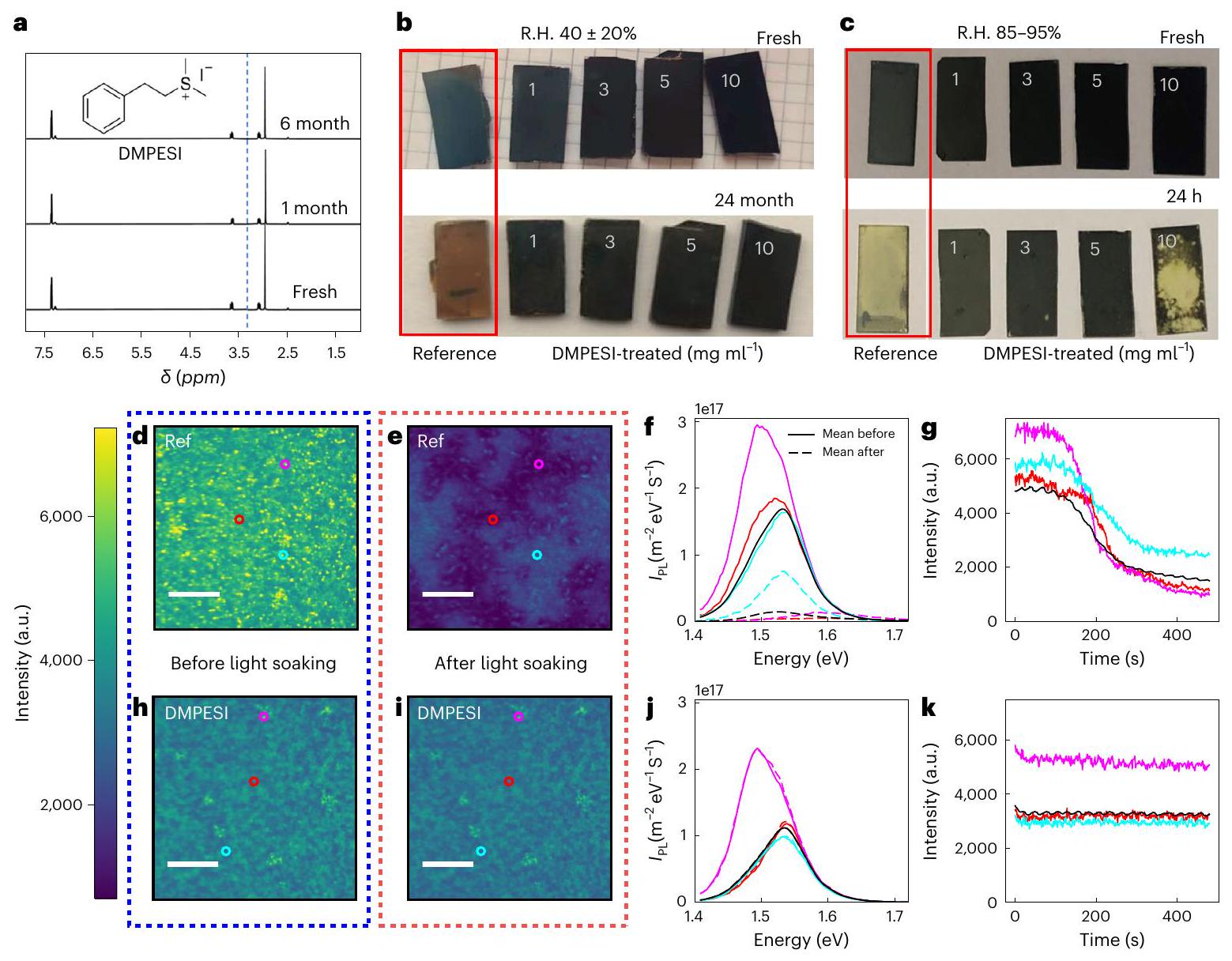
تثبيت حدود الحبوب والأسطح في طبقة البيروفسكيت أمر حاسم لتمديد متانة خلايا الشمس البيروفسكيتية. هنا قدمنا جزيء قائم على السلفونيوم، يوديد ديميثيلفينيثيلسلفونيوم (DMPESI)، للمعالجة بعد الترسيب لأفلام بيروفسكيت يوديد الرصاص الفورماميدينيوم. تظهر الأفلام المعالجة استقرارًا محسنًا عند التعرض للضوء وتظل باللون الأسود المرحلة بعد عامين من التعتيق تحت ظروف البيئة المحيطة بدون تغليف. تظهر خلايا الشمسية البيروفيسكايت المعالجة بـ DMPESI فقدان أداء أقل من 1% بعد أكثر من عند تتبع نقطة القدرة القصوى، مما ينتج عنه نظريًا لأكثر من تسع سنوات تحت إضاءة مستمرة بمقدار 1-شمس. كما تظهر الخلايا الشمسية أقل من انخفاض كفاءة تحويل الطاقة تحت ظروف الشيخوخة المختلفة، بما في ذلك 100 دورة حرارية بين و واختبار رطوبة حرارية لمدة 1,050 ساعة.

الكفاءة، الاستقرار، وقابلية التوسع هي العوامل الأكثر أهمية في الطريق نحو تسويق خلايا الشمس البيروفيسكايتية (PSCs). تم تحقيق كفاءات تحويل طاقة معتمدة ملحوظة بلغت 25.7% في خلايا بيروفيسكايت أحادية الوصلة و32.5% في خلايا شمسية تانديم بيروفيسكايت-سيليكون. . مؤخرًا، تم أيضًا إدارة القابلية للتوسع بشكل فعال من خلال تعديل طبقات نقل الشحنة والمعالجات البينية باستخدام تقنيات ترسيب قابلة للتوسع، مما مكن من تحقيق كفاءات تحويل طاقة معتمدة بلغت 23.1 و22.7 و في 1، 24 و الخلايا والوحدات المصغرة، على التوالي على الرغم من أن الاستقرار قد تحسن بشكل ملحوظ، إلا أنه لا يزال يمثل القيد الأكثر حرجًا لتسويق الخلايا الشمسية عالية الكفاءة القائمة على البيروفسكايت المتطورة، وهناك حاجة ماسة إلى مزيد من التحسين. .
يبدأ كل من فقدان الأداء وتدهور خلايا الطاقة الشمسية عند حدود الحبوب والواجهات، حيث تميل العيوب والأيونات المتحركة
للتراكم تحت الضغط الخارجي، مثل الإضاءة المستمرة، والبيئة الرطبة، وارتفاع درجة الحرارة لذلك، فإن كبح عيوب السطح إلى جانب تثبيط هجرة الأيونات المتحركة أمر حاسم لتحقيق استقرار طويل الأمد لخلايا PSCs. تم استكشاف أنواع جزيئية مختلفة لكبح تكوين العيوب وهجرة الأيونات سواء في كتلة البيروفسكايت أو عند الواجهات المجاورة، بهدف نهائي هو تحقيق خلايا PSCs مستقرة. تشمل هذه الأنواع أملاح الأمونيوم، الجزيئات العضوية الصغيرة، البوليمرات وعوامل التمرير الأخرى بما في ذلك الأملاح غير العضوية. فئة من الجزيئات القائمة على السلفونيوم غير البروتيني تظهر إمكانات كبيرة في تثبيت خلايا الطاقة الشمسية ذات المركبات الهجينة (PSCs)، ومع ذلك، لا تزال غير مستكشفة إلى حد كبير. . إن ابتكار استخدام مثل هذه المواد لتثبيت خلايا البيروفوفسكايت الشمسية مدفوع بالهندسيات الفريدة مع استقرار كيميائي ورطوبي معزز بشكل كبير توفره الكاتيونات القائمة على السلفونيوم. على سبيل المثال، بيروفوفسكايت أحادي البعد ( )
الشكل 1| استقرار جزيء DMPESI وأفلام البيروفسكايت المعالجة تحت ظروف الرطوبة والتعرض للضوء. أ، طيف الرنين المغناطيسي النووي لـ DMPESI في DMSO-d6 الخالي من الماء بعد ستة أشهر من التخزين في الهواء المحيط. الذروة في DMSO-d6 عند 3.3 جزء في المليون (الخط الأزرق المتقطع العمودي): الإشارة غائبة في العينات. تم عرض البنية الكيميائية لـ DMPESI. ب، صور لفيلم البيروفسكيت غير المغلف الطازج والمعتق لمدة 24 شهرًا (1.0 سم × 2.0 سم) بدون ومع معالجة DMPESI بتركيزات مختلفة (من اليسار إلى اليمين: المرجع، ) في الهواء المحيط مع الرطوبة النسبية . ج، صور فوتوغرافية لفيلم بيروفسكايت غير مغلف طازج وعمره 24 ساعة (1.0 سم × 2.0 سم) بدون ومع معالجة DMPESI بتركيزات مختلفة (من اليسار إلى اليمين: المرجع، ) في ظروف رطوبة نسبية عالية تتراوح بين 85~95%. (د، هـ، ح، ط) الفلورة الضوئية الطيفية الفائقة
المجهرية لـ الأفلام المرجعية والمعالجة بـ DMPESI، مقياس الرسم . د، هـ، خريطة الفوتولومينيسنس (PL) للمرجع الفيلم قبل (د) وبعد (هـ) 10 دقائق من التعرض للضوء في الهواء عند شدة إضاءة تعادل شمس واحدة باستخدام ليزر مستمر الموجة بطول موجي 405 نانومتر. و. أطياف الانبعاث الضوئي قبل (خطوط متصلة) وبعد (خطوط متقطعة) الضوء من النقاط الملونة المحددة في اللوحات و . يتم تمييز الطيف المتوسط للانبعاث الضوئي للمنطقة باللون الأسود. هي شدة الانبعاث الضوئي. ج، تغيرات شدة الانبعاث الضوئي مع تعرض المناطق المحددة للضوء في ومتوسط الصورة (أسود). h,i، خريطة شدة الفلورة الضوئية للفيلم المعالج بـ DMPESI قبل (h) وبعد (i) 10 دقائق من تعرضه للضوء (ما يعادل ضوء الشمس لمدة ثانية واحدة). j، أطياف الفلورة الضوئية قبل (خطوط متصلة) وبعد (خطوط متقطعة) تعرض المناطق المحددة للضوء في و i. k، تتغير شدة PL مع تعرض المناطق المحددة للضوء في ومتوسط الصورة (الأسود).
تم تحضير كاتيون التريميثيلسلفونيوم، الذي يظهر استقرارًا كيميائيًا مرتفعًا وبالمثل، تم إدخال يوديد بوتيل ديميثيل سلفونيوم مشبع بالكامل في البيروفسكيت، والذي أظهر تحسناً ملحوظاً في استقرار الجهاز تحت ظروف الرطوبة. . ومع ذلك، فإن الذوبانية المنخفضة لأملاح السلفونيوم الأليفاتية هذه في المذيبات القطبية المنخفضة (مثل الأيزوبروبانول والكلوروفورم) يحد من تطبيقها في معالجة الأسطح.
في هذا العمل، قمنا بتخليق وتقديم كاتيون ديميثيلفينيثيلسلفونيوم غير مستكشف وملحه اليوديدي، DMPESI (الشكل 1أ، الإدراج)، المزود بجزء عطري، واستخدمناه كعامل تمرير للسطح على -المستندة إلى PSCs. نحن نفترض أن الطبيعة العطرية للرباط تحفز تعبئة محكمة على سطح البيروفيسكايت مقارنة بالسلاسل الأليفاتية. تشير النتائج إلى أن معالجة سطح البيروفيسكايت خطوة واحدة باستخدام DMPESI تحقق بفعالية سلسلة من الفوائد: فهي تعالج عيوب السطح، مما يطيل عمر حاملات الشحنة ويكبح إعادة التركيب غير الإشعاعي، مما يؤدي إلى أداء متفوق لـ PSCs؛ كما تعزز الاستقرار الديناميكي الحراري للون الأسود ، مما يمنع الانتقال الطوري إلى المرحلة؛ حيث يحفز تكوين طبقة تغطية مدمجة فائقة الكراهية للماء على السطح
من سطح البيروفيسكايت، مما يعيق هجرة الأيونات ويعيق آليات التدهور الناجمة عن البيئة المحيطة. وبالتالي، فإن المعالجة بـ DMPESI يعرض الفيلم استقرارًا محسنًا بشكل كبير عند تعرضه للضوء ويظل في الطور الأسود بعد عامين من التعرض للظروف المحيطة. علاوة على ذلك، تظهر خلايا الطاقة الشمسية ذات الكفاءة العالية الناتجة (PCE > 23%) استقرارًا طويل الأمد، حيث تظهر انخفاضًا ضئيلًا في الكفاءة (أقل من 1%) بعد أكثر من 4500 ساعة من تتبع نقطة القدرة القصوى، وهو من بين أكثر خلايا الطاقة الشمسية استقرارًا تشغيليًا التي تم الإبلاغ عنها حتى الآن؛ حيث تحتفظ بأكثر من 96% من الأداء الأولي دون تغليف عند مع رطوبة نسبية (R.H.) أقل من 30% بعد 400 ساعة من التعرض للشيخوخة؛ تحتفظ الأجهزة المغلفة بأكثر من 98% من أدائها الأولي تحت دورات الحرارة، وفقًا لبروتوكول الاستقرار لقمة الاستقرار الدولية للخلايا الشمسية العضوية (ISOS)؛ تجتاز الأجهزة المغلفة بنجاح اختبار الرطوبة والحرارة ( في R.H.) لأكثر من 1000 ساعة مع فقدان أقل من 5% في كفاءة تحويل الطاقة (PCE). توفر هذه المتانة الممتازة لفيلم البيروفسكيت المعالج بـ DMPESI وأجهزة خلايا البيروفسكيت الشمسية (PSC) دليلاً قوياً على أن أفلام البيروفسكيت الرقيقة لديها القدرة على الوفاء بالبروتوكولات الصناعية والمنافسة مع الخلايا الشمسية القائمة على السيليكون للإنتاج على نطاق واسع وصناعي مستقبلي.

ثبات فيلم البيروفسكيت تحت الرطوبة والتعرض للضوء

بدأنا بتقييم استقرار ملح DMPESI عن طريق تخزينه في الهواء المحيط مع رطوبة نسبية تبلغ وتتبعه باستخدام الرنين المغناطيسي النووي ( قياس الرنين المغناطيسي النووي (NMR). كما هو واضح من الطيف في الشكل 1أ، لا يوجد تم الكشف عن ذروة بعد ستة أشهر من التخزين. من المتوقع أن تحسن خاصية امتصاص الماء المنخفضة لمركب DMPESI غير البروتوني من خاصية كراهية الماء لفيلم البيروفسكايت بعد معالجة السطح، وبالتالي استقرار الجهاز، خاصة في الظروف الرطبة. خاصية كراهية الماء لمركب DMPES ضد كاتيون فينيثيلأمونيا المرتبط القائم على الأمونيوم ( ) يتم تأكيد ذلك من خلال رسم خريطة الجهد الكهروستاتيكي لكلتا الأيونين الموجبَين، كما تم اشتقاقه بواسطة حسابات نظرية الكثافة الوظيفية (DFT) (ملاحظة تكميلية 1)، والتي تُظهر منطقة ذات قطبية عالية بالقرب من مجموعة الأمونيوم في ، الذي يفتقر إلى في وبالمثل، تظهر طاقات التحلل الحراري وطاقات تفاعل الماء المحسوبة لكل من الكاتيونات بوضوح انخفاض الميل لارتباط الماء في DMPES ضد PEA .
نودع طبقة من من DMPESI على سطح فيلم بيروفسكايت ثلاثي الأبعاد، حيث ثلاثي يوديد الرصاص الفورماميدينيوم ( ) يتم اختياره، نظرًا لفجوة النطاق الملائمة لأداء عالي في خلايا الطاقة الشمسية ذات الطبقة الرقيقة (PSCs) تم عرض مورفولوجيا أفلام البيروفسكيت في الشكل التكميلي 2. يصبح فيلم بيروفسكيت متعدد البلورات كثيف وخالٍ من الثقوب الدقيقة بحبيبات بحجم ميكرومتر أكثر تجانسًا عند معالجة السطح حتى مع كمية قليلة ( ) من DMPESI. مع زيادة تركيز DMPESI إلى و ، لا يزال يُلاحظ سطح موحد وناعم، ومع ذلك، تظهر أنواع جديدة أيضًا. ومن الجدير بالذكر، عندما تزداد تركيز DMPESI بشكل أكبر إلى ، لوحظت بعض التشققات على سطح البيروفيسكايت، والتي قد تكون ناتجة عن تجمع فائض DMPESI.
تم إجراء قياسات زاوية التماس لقطرات الماء على السطح لتقييم استقرار الرطوبة لفيلم البيروفسكايت (الشكل التكميلي 3). لوحظ زيادة ملحوظة في زاوية التماس من من البيروفسكايت المرجعي إلى حوالي من الأفلام المعالجة بـ DMPESI، بغض النظر عن التركيز، مما يشير إلى سطح أكثر كراهية للماء بعد المعالجة. ثم عرضنا أفلام البيروفسكايت للهواء المحيط. أصبح الفيلم المرجعي بنيًا بعد التعرض لمدة عشرة أيام. في المقابل، الأفلام البيروفسكايت المعالجة بـ و تظل DMPESI في الطور الأسود النقي تحت نفس الظروف حتى بعد 24 شهرًا (الشكل 1ب والشكل التكميلي 4)، كما يتضح من أنماط حيود الأشعة السينية (XRD) للعينات المعتقة في الشكل التكميلي 5. قمنا أيضًا بتعريض أفلام البيروفسكايت لرطوبة نسبية عالية تتراوح بين 85-95%. تُظهر الصور الفوتوغرافية للأفلام في الشكل 1ج والشكل التكميلي 6، وتمت مراقبة أنماط XRD المقابلة لها في الشكل التكميلي 7. بعد التعرض لمدة 24 ساعة، يمر فيلم البيروفسكايت المرجعي بتحول سريع من الطور الأسود إلى الطور الأصفر. . بالإضافة إلى ذلك، القمة عند لـ (110) يظهر انخفاضًا حادًا في الشدة، مما يشير إلى بلورية بيروفسكايت أدنى مع مناطق غير مرتبة أكبر بين الحبيبات. . ومع ذلك، على النقيض تمامًا، الأفلام المعالجة بكميات معتدلة ( و ) من DMPESI يحتفظ في الطور الأسود من المثير للاهتمام، أن فيلم البيروفسكيت المعالج بكمية زائدة من DMPESI ( ) يظهر عدم استقرار في الطور متفاقم. نعزو ذلك إلى التغطية السطحية الضعيفة الناتجة عن تجمع فائض DMPESI، كما يدعمه صورة المجهر الإلكتروني الماسح (SEM) الملاحظة في الشكل التكميلي 2، والتي قد تؤدي إلى مسارات تحلل تسمح للرطوبة من الغلاف الجوي الخارجي بالتسلل إلى كتلة البيروفسكايت، مما يؤدي إلى تسريع عملية التحلل.
لمزيد من التحقيق في استقرار التعرض للضوء للمرجع والمعالج بـ DMPESI ( ) الأفلام، قمنا بإجراء رسم خرائط طيفية ضوئية واسعة النطاق لكلتا العينتين في الظروف المحيطة. تعرض خرائط الطيف الضوئي الطيفي (الشكل 1د، 1ح) توزيعات ضوئية مكانية مماثلة مع شدة انبعاثات ومواقع قمم متقاربة وانبعاث ضوئي إضافي صغير منحرف نحو الأحمر. تُظهر العينة المعالجة بـ DMPESI انبعاثًا معززًا منخفض الطاقة حول حواف الحبوب مقارنةً بالعينة المرجعية (الشكل التوضيحي التكميلي 8). ثم تم تعريض العينات للضوء
تم نقعها لمدة 10 دقائق تحت شدة إضاءة تعادل شمس واحدة في ظروف محيطة. تُظهر الخرائط المقابلة لنفس مناطق العينات المرجعية والمعالجة في الشكل 1e و1i على التوالي. من الجدير بالذكر أن شدة العينة المرجعية تنخفض بشكل كبير أثناء الإضاءة وتظهر مناطق مميزة بحجم عشرات الميكرونات ذات انبعاث ضوئي أعلى أو أقل (الفيديو التكميلي 1). كما هو موضح في الشكل 1f والشكل التكميلي 9، فإن المناطق التي تفقد أكبر قدر من الشدة تظهر أيضًا تحولًا أزرقًا دراماتيكيًا في الانبعاث الضوئي. وظهور قمة ثانية عند طاقة أعلى بكثير تقترب من 2 إلكترون فولت. وهذا يشير إلى أن المرجع الطور غير مستقر للغاية وعلى مدار عشر دقائق من التعرض للضوء، تظهر مراحل/تراكيب جديدة متعددة، مما يؤثر سلبًا على جودة المادة البصرية الإلكترونية. المناطق التي تحتفظ بأعلى شدة انبعاث ضوئي (PL) تنخفض فقط في الشدة دون أي تغير في الذروة. يتم تسليط الضوء بشكل أكبر على عدم استقرار العينة المرجعية في الشكل 1g، الذي يرسم شدة الانبعاث الضوئي المتكاملة في نقاط مختلفة على العينة. بالمقابل، تظهر العينة المعالجة بـ DMPESI سلوكًا مختلفًا بشكل ملحوظ. حيث لا تظهر العينة المعالجة أي سلوك عابر فعليًا خلال نفس الفترة الزمنية، مع تغييرات ضئيلة جدًا في شدة الانبعاث الضوئي، التوزيع المكاني أو الطيف كما هو موضح في الشكل 1i-k والفيديو التكميلي 2. تظهر هذه النتائج مجتمعة أن معالجة DMPESI قد حولت مادة غير مستقرة بطبيعتها إلى مادة أكثر استقرارًا بكثير على المستويين الكلي والجزئي.

الآلية الذرية مع البيروفسكايت

لاستكشاف الأسباب الكامنة وراء استقرار طبقة البيروفيسكا المعالجة بـ DMPESI، أجرينا حسابات DFT لطبقات DMPESI الممتصة ويوديد فينيل إيثيل أمونيوم (PEAI) على – وأساطح البيروفسكيت المنتهية بيوديد الفورماميدينيوم (FAI) بتغطية سطحية مختلفة، كما هو موضح في الشكل 2أ، ب للأنظمة ذات التغطية الكاملة (النهج التفصيلي في المعلومات التكميلية). تفاعل وحدة واحدة من DMPESI أو PEAI على PbI -تُوفر السطح المنتهي لنا قوة سطح الملح/البيروفسكايت، خاليًا من تفاعلات التعبئة بين الجزيئات (الشكل التكميلي 10ج-هـ). يوضح الجدول التكميلي 2 أن الامتزاز التفككي لأملاح اليوديد، مع تكوين سطح الرابطة، مفضلة بشدة في DMPESI مقابل PEAI (2.09 مقابل 1.74 إلكترون فولت) وتتجاوز بفعالية رابطة FAI السطحية طاقة التفاعل القوي هي شرط أساسي لمنع ذوبان السطح بفعالية أثناء تشغيل الجهاز. عند نصف التغطية، لا يزال ارتباط DMPESI مفضلاً على PEAI (1.93 مقابل 1.71 إلكترون فولت لكل جزيء) على الرغم من أن PEAI يشكل طبقة أكثر تماسكًا قليلاً (الشكل التكميلي 10f-g والجدول التكميلي 2). من المدهش، عند التغطية الكاملة، يفضل DMPESI تكوين طبقة علوية (حوالي نصف الجزيئات المتفاعلة لا ترتبط بسطح البيروفسكايت) في حين يشكل PEAI طبقة أحادية مرتبة (الشكل التكميلي 10h,i)، مع طاقات تفاعل متقاربة تهيمن عليها التفاعلات بين الجزيئات. غياب الروابط الهيدروجينية الاتجاهية في DMPESI القائم على السلفونيوم لا يؤدي إلى ترتيب جزيئي منظم كما هو موجود في ملح PEAI المزود بـ R- المجموعات. على سطح بيروفسكايت مكتمل الإنهاء بـ FAI، يشكل DMPESI أيضًا طبقة واقية قوية مع طاقة تفاعل معززة (1.69 مقابل 1.28 إلكترون فولت) تهيمن عليها قوى التشتت (الشكل التكميلي 101، م). وبالتالي فإن DMPES يمكن أن يساعد بشكل فعال في تغليف الأنيونات اليودية المتنقلة عبر مجموعات السلفونيوم والحلقات الفينيلية في إطار DMPESI. يمكن لهذا التغليف أيضًا تقليل وجود عيوب اليود البينية عند -سطح منتهي، والذي ثبت أنه مركز لاحتجاز الثقوب . علاوة على ذلك، تظهر الخصائص الإلكترونية للطبقة الممرضة المغطاة بطبقة DMPESI تقليلًا في مصائد السطح مقارنةً بالطبقة العارية -سطح منتهي ، حتى إذا تم تمرير نصف ذرات الرصاص المعرضة فقط بواسطة اليوديد، كما هو موضح في الشكل التكميلي 11. في هذه الحالة، لا يُدخل الطبقة البينية تغييرات ملحوظة على البنية الإلكترونية مقارنةً بالسطح المنتهي بـ FAI العاري (الشكل التكميلي 11). كل من DMPESI و PEAI قادران أيضًا على تمرير فراغات سطح FAI بفعالية (الشكل التكميلي 10n,o).
بشكل عام، تشير تحليلاتنا إلى السمات البارزة لتفاعل DMPESI/ البيروفسكايت التي تجعل هذا الملح مختلفًا عن المعيار.
الشكل 2 | البنية المجهرية لأفلام البيروفيسكا والتفاعلات بين DMPESI و نماذج DFT لواجهة التغطية الكاملة للبروفيسكايت عند والأسطح المنتهية بـ FAI- (ب). يتم استخدام رمز الألوان التالي للتمثيلات الذرية: بنفسجي، I؛ سماوي، Pb؛ أزرق، N؛ أصفر، S؛ أخضر، C؛ أبيض، H. ج، صورة المجال الداكن الحلقية المعاد بناؤها من بيانات SED لفيلم البيروفيسكايت المعالج بـ DMPESI. د، أنماط حيود الإلكترون المستخرجة من المنطقة داخل الحبيبات معروضة. هـ، صورة المجال الداكن الحلقية المعاد بناؤها من بيانات SED للفيلم المرجعي. التفاعل على المستوى الذري بين و DMPESI من NMR الحالة الصلبة.
كمي، f طيف الرنين المغناطيسي النووي MAS لـ DMPESI (أزرق) و DMPESI المعالج تم تحضيرها كأفلام رقيقة مطلية بالدوران (باللون الأحمر). طيف انتشار الدوران لعينة معالجة بـ DMPESI تم تحضيرها كأفلام رقيقة مطلية بالدوران (50 كيلوهرتز MAS، 23 تسلا). يُظهر المقطع العرضي الأفقي عند 3.4 جزء في المليون (الخط المتقطع) باللون الأخضر. يُعرض طيف DMPESI باللون الأخضر في اللوحة f. طيف MAS بالاستقطاب المتقاطع لـ DMPESI و DMPESI المعالج تم تحضيره كطبقة رقيقة مصبوبة. FA هو الفورماميدينيوم، CP هو الاستقطاب المتقاطع، هي 4 أضعاف شدة الإشارة.
PEAI. بشكل أساسي، يمكن لـ DMPESI أن يرتبط بقوة بسطح البيروفسكايت مكونًا طبقة سطحية كارهة للماء. التفاعل السطحي القوي يثبت طبقة البيروفسكايت وربما يقفلها في الطور الأسود. ومع ذلك، عند تغطية عالية، يؤدي التنافس بين التفاعلات السطحية/الجزيئية والتفاعلات بين الجزيئات إلى تكوين طبقة علوية من DMPESI، والتي قد تحد من استخراج الشحنة وإلى حد ما تمنع التمرير الكامل للسطح.
تم إجراء قياسات حيود الإلكترون الماسح (SED) لفهم تأثير DMPESI على البنية الدقيقة لفيلم البيروفسكايت. . تكشف صورة المجال المظلم الحلقي (ADF) المعاد بناؤها من بيانات SED عن تباين في تباين الانعراج عبر فيلم البيروفسكايت مع ظهور مناطق أكثر سطوعًا بين الحبوب المميزة، كما هو موضح في الشكل 2ج. يكشف فحص نمط SED المستخرج من إحدى الحبوب عن حبة بيروفسكايت موجهة بالقرب من محور المنطقة. وجود انعكاسات البنية الفائقة، المحظورة من
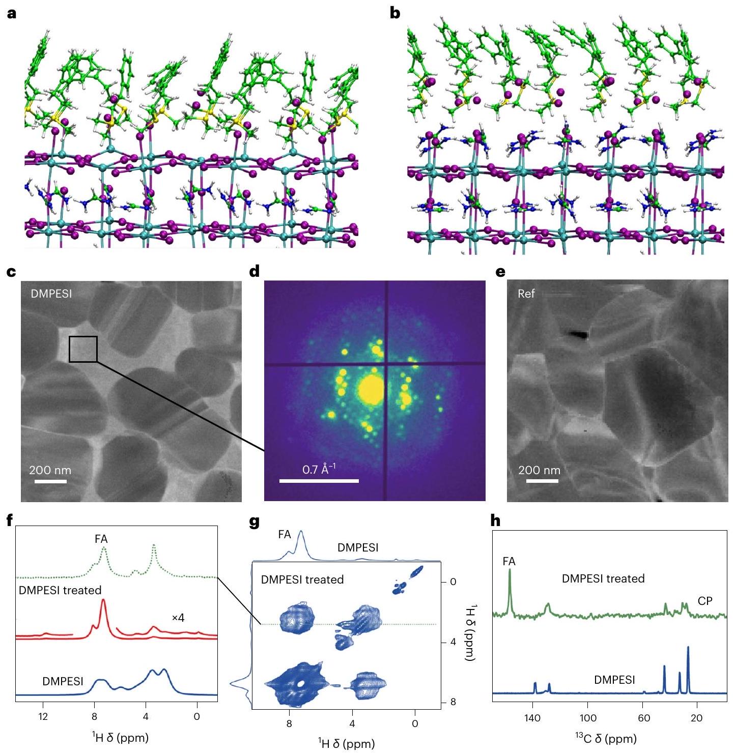
الظهور في طور البيروفيسكا المكعب (الأسهم البيضاء في الشكل التكميلي 12ب)، يشير إلى وجود إمالة ثمانية السطوح، والتي ثبت أنها تعيق الانتقال الطوري من البيروفيسكا الغنية بـ FA النشطة ضوئيًا إلى البيروفيسكا غير النشطة ضوئيًا مرحلة . فحص نمط SED المستخرج من منطقة داخل الحبيبات – الشكل 2د (بالمقارنة مع الفيلم المرجعي في الشكل 2هـ) – يشير إلى وجود طور بلوري إضافي، والذي يمكن ملاحظته أيضًا من خلال أشكال الانبعاث، الموضحة في الشكل التكميلي 8. وبالاقتران مع النتائج التي تم الحصول عليها من حيود الأشعة السينية (XRD) وانتشار الأشعة السينية بزوايا ميلان واسعة (GIWAXS)، الموضحة في الشكل التكميلي 13، نشتبه في أن متجهات الحيود القصيرة يمكن أن تُعزى على الأرجح إلى هياكل بيروفسكايت منخفضة الأبعاد تشكلت بين حبيبات 3DFAPBI الكتلة عند معالجة DMPESI. كما لوحظ ميل ثماني السطوح في فيلم البيروفسكيت المرجعي، كما هو موضح في الشكل التكميلي 12د، هـ. من المحتمل أن ينشأ هذا من سبك كمية أثرية من على الأي
الشكل 3 | الخصائص البصرية الكهربائية لأفلام البيروفسكايت وأداء أجهزة الخلايا الشمسية. أ، تحلل الفلورة العابرة للعينات المرجعية والمغطاة بـ DMPESI ) أفلام البيروفسكايت على الزجاج مع وبدون طبقة النقل الحاملة للشحنة (HTL). تم الحصول على التوافقات من دالة الانحلال متعددة الأسس، والتي استخدمت لحساب أوقات الحياة التفاضلية. الكرات الملونة المشبعة تمثل تحلل الانبعاث الضوئي (PL) للبيروفسكايت على الزجاج (الموضح في المربع الرمادي) مع (باللون الأحمر) وبدون (باللون الأسود) DMPESI. الدوائر الملونة غير المشبعة تمثل تحلل الانبعاث الضوئي للبيروفسكايت على الزجاج مع طبقة النقل الحاملة للشحنة على السطح (الموضحة في المربع البنفسجي). ب، ج، وقت الانحلال التفاضلي لأفلام البيروفسكايت المعالجة بطبقة النقل الحاملة للشحنة مرسوم كدالة للزمن بعد الإثارة (ب) وانقسام مستوى فيرمي شبه (ج). مع زيادة تركيز DMPESI، يزداد قمع إعادة التركيب السطحي.
أيضًا (حتى )، لكن كفاءة استخراج الشحنة تنخفض. د، منحنيات التحكم (بالأسود) و( ) الأجهزة المعالجة بـ DMPESI (باللون الأحمر)، المسح العكسي (RS) والمسح الأمامي (FS) موضحان بالرموز الصلبة والرموز المفتوحة على التوالي. الجدول المدرج يلخص معلمات الخلايا الكهروضوئية المقابلة. هـ، كفاءة تحويل الطاقة (PCE) للجهاز الذي يستخدم DMPESI ( ) جهاز المعالجة عند نقطة القدرة القصوى كدالة للزمن في درجة حرارة الغرفة (درجة حرارة الغرفة)، تحت الظروف المحيطة، بدون تغليف. مقابل لوغاريتم شدة الضوء للخلايا الشمسية مع وبدون معالجة DMPESI مع التناسبات الخطية المقابلة، والتي تم من خلالها تحديد المنحدرات بواسطة عوامل المثالية (1.38 لـ DMPESI و1.74 للمجموعة الضابطة). هو ثابت بولتزمان، T هي درجة الحرارة و هو الشحنة الأولية.
موقع مع ويمنح درجة من الاستقرار (أي أن الفيلم المرجعي لا يتحول بالكامل إلى المرحلة على الفور)، على الرغم من أنها ليست كافية لتثبيت فيلم البيروفيسكايت بشكل قوي. ومع ذلك، فإن التأثير التآزري لـ DMPESI عند حدود الحبوب والانحناء الهيكلي المثمن يحقق بنجاح فيلم بيروفيسكايت فائق الاستقرار عند المعالجة.
لتقييم التفاعل المجهري بين DMPESI و فيلم، أجرينا قياسات الرنين المغناطيسي النووي بالدوران عند زاوية السحر في الحالة الصلبة (MAS) الرنين المغناطيسي النووي و الرنين المغناطيسي النووي (NMR) عالي الدقة طيف الرنين المغناطيسي النووي للماس لأفلام رقيقة من المُمرَّضة بـ DMPESI موضحة في الشكل 2f-h. في حين أن الإشارات العطرية لـ DMPESI ( ) تتداخل مع تلك الخاصة بـ FA في الشكل 2f، الطيف ( ) يحتوي على إشارات تنشأ من الجزء الأليفاتي لـ DMPESI. هناك فرق نوعي في المنطقة الأليفاتية بين DMPESI و DMPESI المعالج فيلم، مما يشير إلى أنه في الحالة الأخيرة، يكون DMPESI في شكل كيميائي مختلف. علاوة على ذلك، أجرينا تجربة انتشار الدوران التي تستكشف التقاربات عبر التفاعلات الثنائية للغاطس المغناطيسي بين البروتونات (الشكل 2ج). على الرغم من التداخل الكبير في الإشارة المذكور أعلاه، من الواضح أن إشارة الأليفاتية لـ DMPESI عند 3.4 جزء في المليون لها ارتباط ثنائي قطبي بين الجزيئات مع FA بدلاً من
فقط ارتباط ثنائي القطب داخل الجزيء مع بروتونات العطرية لـ DMPESI. يتضح هذا بناءً على شكل ذروة التقاطع، التي تحتوي على مكونين يتطابق موقعهما ونسبة شدتهما تمامًا مع إشارة FA (الشكل 2ج، المسار الأخضر). لتعزيز التحقق من تفاعل DMPESI مع ، قمنا بعد ذلك بتنفيذ قياسات NMR بتقنية MAS على الأفلام الملقاة بالتنقيط (الشكل 2ه)، والتي تظهر تغييرات كبيرة في بنية DMPESI في المادة الصلبة. كما هو موضح من طيف الاستقطاب المتقاطع (CP)، الذي يكتشف البيئات المحلية الصلبة فقط، فإن قمم DMPESI العطرية والأليفاتية تتحرك وتتسع مقارنة بـ DMPESI، مما يكشف عن التفاعل و/أو التفاعل بين DMPESI و تُقدَّم مناقشات أكثر تفصيلاً لبيانات الرنين المغناطيسي النووي في الحالة الصلبة في الملاحظة التكميلية 3.
علاوة على ذلك، للتحقيق في تركيب الأنواع الجديدة التي تتكون عند معالجة DMPESI، قمنا بتخليق نسب مختلفة من البيروفسكايتات منخفضة الأبعاد المحتملة وقارنّا أنماط حيود الأشعة السينية الخاصة بها، كما هو موضح في الشكل التكميلي 14. ومن المثير للاهتمام، القمتان العريضتان ( و ) لوحظ في فيلم البيروفيسكايت المعالج بكمية تزيد عن المثلى من DMPESI ( ) لا يمكن تعيينها لأي نوع بيروفسكايت أحادي البعد منخفض ولكنها تظهر عند نفس زوايا الانعراج في مزيج من
الشكل 4 | متانة خلايا الطاقة الشمسية ذات الطبقة السميكة (PSCs). أ، استقرار الرف في الظلام لخلايا PSCs غير المغلفة كتحكم والمُعالجة بـ DMPESI، والصور المدرجة هي الأجهزة قبل وبعد التعرض للشيخوخة في الظروف المحيطة عند درجة حرارة الغرفة مع رطوبة نسبية حوالي ، خمسة أجهزة لكل حالة، كانت كفاءة الأجهزة الأولية PCEs هي (معالجة DMPESI) و (التحكم). ب، أنماط حيود الأشعة السينية للخلايا الشمسية الضوئية المعالجة بـ DMPESI والمتحكم بها بعد تخزينها على الرف. ج، دورات درجة الحرارة ( ) اختبار الأجهزة المغلّفة والمتحكم بها والمعالجة، خمسة أجهزة لكل حالة. د، اختبار الرطوبة والحرارة ، R.H.) للأجهزة المغلفة والمجهزة، خمسة أجهزة لكل حالة. كانت كفاءات تحويل الطاقة الأولية للأجهزة المختبرة بدورات الحرارة والرطوبة العالية هي (معالجة DMPESI) و (التحكم). البيانات
تُعرض كقيم متوسطة المسح الإلكتروني الماسح لـ a و c و d. e، الاستقرار التشغيلي طويل الأمد للأجهزة الضابطة وغير المغلفة والمعالجة تحت MPPT مع إضاءة مستمرة بسطوع شمس واحد التدفق عند درجة حرارة الغرفة. التوفيق الخطي لاستقرار نقطة القدرة القصوى للجهاز المعالج بـ DMPESI، كفاءة الجهاز الأولية هي 22.68% (معالج بـ DMPESI) و20.43% (التحكم). و، الاستقرار التشغيلي لأجهزة الخلايا الشمسية العضوية عالية الكفاءة المتقدمة (كفاءة > 22%) المستخرجة من الأدبيات. (تركيبة البيروفسكايت بناءً على) موسومة بنقاط خضراء؛ الكاتيون المختلط-الهاليد المختلط موسوم بنقاط زرقاء؛ عملنا موسوم بنجمة حمراء). ملفات عمق ToF-SIMS للأجهزة الجديدة والمعتقة (الضابطة والمعالجة) لـ و .
DMPESI و تشير هذه النتيجة إلى أنه على عكس أملاح الأمونيوم، التي عادةً ما تشكل بيروفسكايتات منخفضة الأبعاد نقية عند معالجة السطح، فإن DMEPSI تميل إلى التفاعل مع لتشكيل نوع خليط، والذي يمكن تأكيده بشكل أكبر من خلال التشابه الكبير في مورفولوجيا السطح (الشكل التوضيحي التكميلي 15)، مقارنة بـ فيلم البيروفيسكايت المعالج بـ DMPESI كما هو موضح في الشكل التكميلي 2. وهذا يتفق أيضًا مع حسابات DFT، التي تكشف عن ميل DMPESI لإقامة تفاعلات بين جزيئية عند تغطية عالية مقارنة بأملاح الأمونيوم الأخرى (أي PEAI) التي تميل إلى تكوين مراحل ثنائية الأبعاد على سطح البيروفيسكايت ثلاثي الأبعاد.

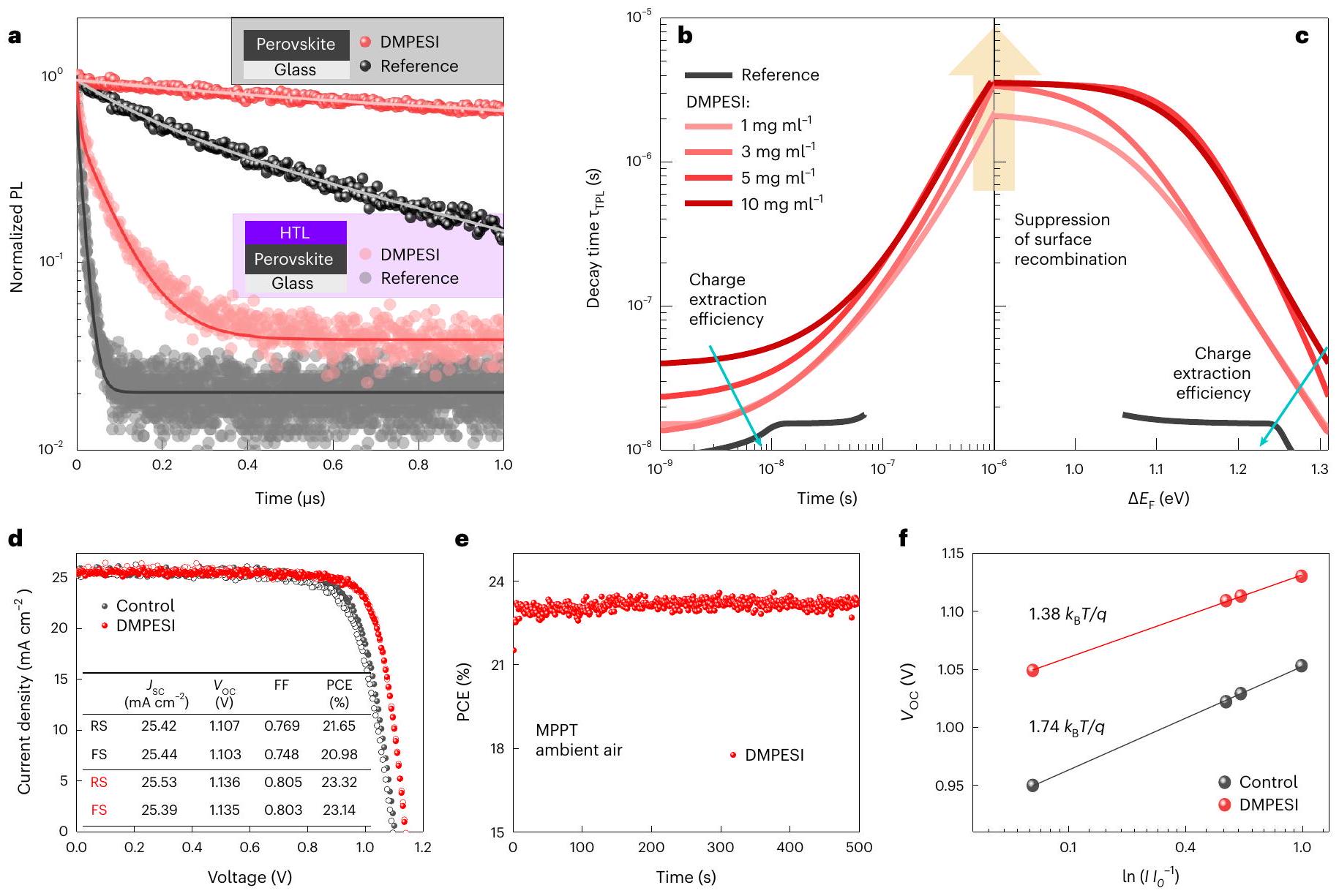
الخصائص البصرية الكهربائية لأفلام وأجهزة البيروفيسكايت

للتحقيق في الخصائص البصرية الإلكترونية لأفلام البيروفيسكايت المعالجة بـ DMPESI مع وبدون طبقة نقل الثقوب (HTL)، تم إجراء قياسات تحلل PL الزمني، كما هو موضح في الشكل 3أ والشكل التكميلي 16، على التوالي. من الواضح أن كميات معتدلة من DMPESI تؤدي إلى إطالة فعالة لعمر حاملات الشحنة تحت نظام الحقن العالي، مما يشير إلى جودة عالية لأفلام البيروفيسكايت مع تقليل ملحوظ في إعادة التركيب غير الإشعاعي. لفك التشابك بين العمليات المتنافسة المختلفة التي تؤدي إلى
نقص حاملات الشحنة الزائدة، استخدمنا عمرًا تفاضليًا ( ) النهج الذي ابتكره كيرشارتز وآخرون نظرًا لأن عمر التفاضلي يعتمد بشكل كبير على حقن حاملات الشحنة ومشتق الفلورة الضوئية مع مرور الوقت، فإنه يوفر معلومات إضافية حول ديناميكيات حاملات الشحنة على مقاييس زمنية مختلفة، مثل آليات الإشعاع من الدرجة الثانية وإعادة التركيب بمساعدة المصائد من الدرجة الأولى. يكشف التآزر بين تحليل عمر التفاضلي والمحاكاة العددية (يمكن العثور على وصف كلا الطريقتين في الملاحظة التكميلية 4) أن العينات المعالجة بـ DMPESI لديها معدل إعادة التركيب السطحي أقل بمقدار مرات. لأن إدخال طبقات انتقائية للشحنة لا ينبغي أن يسبب أي إعادة تركيب غير إشعاعية إضافية، وبالتالي لا يثبط شدة الانبعاث الضوئي على مدى أزمنة أطول تحت حالة الدائرة المفتوحة. . نعزو إطالة بواسطة علاج DMPESI الموضح في الشكل 3ب إلى كبحه الفعال لحالات السطح عند واجهة البيروفسكايت/طبقة النقل الثقيل. ومع ذلك، فإن طبقات DMPESI الأكثر سمكًا ( ) تعيق كفاءة استخراج الشحنة (مرئية في أطر زمنية )، بسبب تراكم الشحنات عند تلامس البيروفيسكايت/DMPESI (الشكل التوضيحي التكميلي 18) دون تقليل إضافي في إعادة التركيب عند الواجهة، كما يظهر من تقارب أوقات الحياة التفاضلية للعينات ذات تركيزات DMPESI المختلفة عند (الشكل 3ج). لذلك، الطبقة التي تم إنتاجها بواسطة يعمل محلول DMPESI على قمع إعادة التركيب غير الإشعاعية بقوة عند واجهة البيروفسكيت/طبقة النقل الحُفرية (HTL)، وفي الوقت نفسه، يسمح باستخلاص فعال للثقب بواسطة طبقة النقل الحُفرية.
تم تصنيع أجهزة PSC بمعالجة DMPESI (تحت ظروف مختلفة) باستخدام الـ هندسة أكسيد القصدير المخدر بالفلور (FTO)/cp- بيروفسكايت/DMPESI/spiro-OMeTAD/ الذهب، بالمقارنة مع الخلايا المرجعية وتلك المعالجة بـ PEAI. تُعرض مخططات الصندوق الإحصائية للمعلمات الكهروضوئية والقيم البطل المقابلة في الشكل التكميلي 19 والجداول التكميلية 6 و7، على التوالي. بالمقارنة مع الأجهزة الضابطة، فإن الأجهزة المعالجة لاحقًا بكمية ضئيلة ( ) من DMPESI تظهر تحسينات طفيفة في جهد الدائرة المفتوحة ( ) وعامل التعبئة (FF)، ومع ذلك، كمية كبيرة ( ) من نتائج DMPESI تؤدي إلى قيم أقل في جميع معلمات PV، والتي نعزوها إلى انسداد انتقال الشحنة عند التكتل وتكوين طبقة وسطية سميكة بين البيروفيسكايت وطبقة النقل الثقيل (HTL)، كما لوحظ في صور SEM للمقطع العرضي في الشكل التكميلي 20. هذه النتيجة تتفق أيضًا مع قياس PL الزمني الذي نوقش أعلاه. كلاهما و FF تزداد بشكل كبير بإدخال كميات معتدلة، خاصةً من DMPESI، مما أدى إلى أفضل كفاءة تحويل طاقة عكسية بنسبة 23.32٪ وكفاءة تحويل طاقة أمامية بنسبة ، كما هو ملخص في الجدول في الشكل 3د. تم تثبيت كفاءة تحويل الطاقة عند تحت نقطة القدرة القصوى، كما هو موضح في الشكل 3e. تم قياس كفاءة تحويل الفوتون الساقط إلى تيار وتم عرضها في الشكل التكميلي 21، والذي يوضح جمع الضوء بكفاءة عبر طيف الامتصاص وله قيمة متكاملة تتفق مع القيمة المقاسة من ال القياس. ومن الجدير بالملاحظة أن التباطؤ في الأجهزة المعالجة يصبح ضئيلاً مقارنة بالأجهزة الضابطة. بالإضافة إلى ذلك، تُظهر الشكل 3f علاقة خطية بين ولوغاريتم شدة الضوء لكل من خلايا PSC الضابطة والمعالجة. من هذا القياس، عامل مثالية الصمام الثنائي ( ) وجد أن قيمة خلية التحكم كانت 1.74، في حين أن الخلية المعالجة لديها ) من 1.38. مثل هذا الانخفاض في يشير إلى كبح فعال لإعادة التركيب بمساعدة الفخ، التي تؤثر بشكل رئيسي على وخسائر FF . على أساس الزائف المعاد بناؤه المنحنيات، كما هو موضح في الشكل التكميلي 22، تبقى خسائر عامل التعبئة المرتبطة بنقل الشحنة شبه ثابتة في وجود DMPESI، في حين يتم تقليل خسائر عامل التعبئة الناتجة عن إعادة التركيب غير الإشعاعي بمقدار النصف. نعزو كبح إعادة التركيب غير الإشعاعي إلى تقليل قوي في كثافة الفخاخ، وهو ما تم تأكيده من خلال قياسات التيار المحدود بالشحنة الفضائية (الشكل التكميلي 23) وحسابات DFT (الشكل التكميلي 11)، متوافقًا جيدًا مع تقليل حالات ذيل الطاقة وطاقة أورباخ (الشكل التكميلي 24). وبالاقتران مع التحليل الموضح سابقًا، نفترض أن إدخال DMPESI على أسطح البيروفسكايت بشكل فعال
يقوم بتمرير الحالات غير المنظمة عند الواجهات وبالتالي يقلل بشكل كبير من إعادة التركيب غير الإشعاعية لتحسين الجهاز و FF.

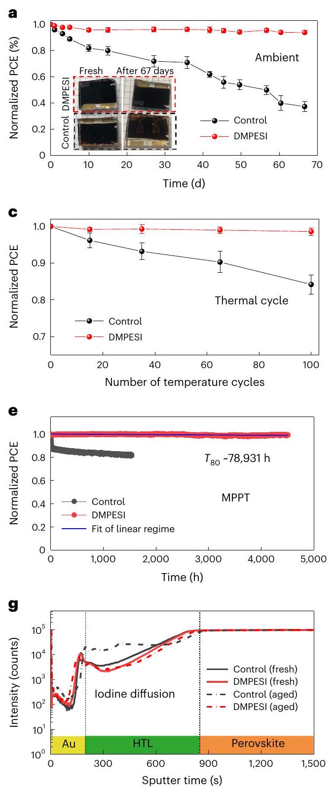
متانة خلايا الطاقة الشمسية ذات التوصيل المباشر

للتحقيق في استقرار خلايا الطاقة الشمسية ذات الحافة البيروفيسكايتية (PSCs)، قمنا أولاً بتتبع استقرار عمرها الافتراضي من خلال تخزين الأجهزة غير المغلفة في الهواء المحيط مع رطوبة نسبية تبلغ لأكثر من شهرين. يوضح الشكل 4 أ أن كفاءة تحويل الطاقة لجهاز التحكم بدون أي معالجة لاحقة انخفضت بنسبة بعد التقدم في العمر لمدة 67 يومًا، في حين أن الجهاز المعالج بـ يحافظ علاج DMPESI على 94% من قيمة PCE الأولية له. يُظهر الفحص البصري للأجهزة قبل وبعد الشيخوخة أن الجهاز الضابط تحول إلى اللون البني الفاتح، مما يشير إلى تحول في الطور أدى إلى انخفاض امتصاص الضوء في الجزء المرئي من الطيف. ظل الجهاز المعالج بـ DMPESI أسود تمامًا، وهو ما تم تأكيده بواسطة تحليل حيود الأشعة السينية (الشكل 4ب). كما تم إجراء اختبار الاستقرار الحراري بتسخين خلايا PSCs غير المغلفة عند مع رطوبة نسبية أقل من من النتائج في الشكل التكميلي 25أ، احتفظت الخلية المعالجة بأكثر من 96% من كفاءة تحويل الطاقة الأولية، في حين احتفظت الخلية الضابطة بأقل من 85% بعد 400 ساعة من التعرض للشيخوخة. علاوة على ذلك، استبدلنا مادة نقل الثقوب (spiro-OMeTAD) بالمادة الأكثر استقرارًا حراريًا وهي بولي(بيس(4-فينيل)(2,4,6-تريميثيلفينيل)أمين) (PTAA) لاختبارات الاستقرار الحراري القاسية. كما هو موضح في الشكل 4ج، لاحظنا تحسنًا كبيرًا في الاستقرار في الأجهزة المعالجة بـ DMPESI (المغلّفة) تحت دورات حرارية (بين إلى ، الإجراء الموضح في الشكل التكميلي 25ب)، وفقًا لبروتوكول استقرار ISOS-T-1 . علاوة على ذلك، نجح الجهاز المعالج والمغلف أيضًا في اجتياز اختبار الرطوبة والحرارة ( في حالة R.H.) لأكثر من مع خسارة أقل من 5% في كفاءة تحويل الطاقة، كما هو موضح في الشكل 4د.
لمزيد من الفحص للعلاج -الخلايا الشمسية ذات التنسيق المعتمد تحت تعرض مكثف للضوء واكتساب رؤى حول آليات التدهور الجوهرية، قمنا بتعريض الخلايا لتتبع نقطة القدرة القصوى (MPPT) تحت إضاءة مستمرة بمقدار شمس واحدة في جو خامل مع التدفق عند درجة حرارة الغرفة. كما هو موضح في الشكل 4e ومنحنى التيار-الجهد المقابل ( ) المعلمات في الشكل التوضيحي التكميلي 26، يُلاحظ بوضوح وجود مرحلة احتراق أولية سريعة خلال أول 30 ساعة في الخلية الضابطة، مما يؤدي إلى فقدان كفاءة تحويل الطاقة (PCE) بنسبة من قيمته الأولية، وهو مشابه لتقارير أخرى عن في الأدب . يُعزى هذا عادةً إلى إعادة توزيع العيوب المشحونة “. بعد ذلك، يظهر تدهور أبطأ في الخلية الضابطة، بسبب التفاعلات الكيميائية غير القابلة للعكس من خلال الهجرة، والتي تسبب تدريجياً تدهورًا لا رجعة فيه للجهاز، مما يؤدي إلى فقدان بنسبة 20% بعد تعتيق تشغيلي لمدة 1500 ساعة. على النقيض تمامًا، يظهر الجهاز المعالج استقرارًا تشغيليًا طويل الأمد استثنائيًا تحت نفس ظروف التعتيق، مع انخفاض ضئيل في كفاءة تحويل الطاقة (أقل من 1%) بعد تعتيق MPPT لنصف عام لأكثر من 4500 ساعة. تجعل هذه النتيجة جهازنا من بين أكثر خلايا PSC استقرارًا وعالية الكفاءة التي تم الإبلاغ عنها حتى الآن، كما هو موضح في الشكل 4f (تم تلخيص المزيد من التفاصيل في الجدول التكميلي 8). تم الحصول على نتيجة مماثلة أيضًا بقياس خلايا أخرى ضمن نفس الدفعة ودفعات مختلفة، كما هو موضح في الشكل التكميلي 27. إجراء استقراء خطي لهذه البيانات يؤدي إلى “نظرية لأكثر من تسع سنوات (الشكل 4هـ) تحت إضاءة مستمرة بمقدار شمس واحدة، وهو ما يتوافق مع تدفق فوتونات لتركيب طاقة شمسية خارجية في السويد أو ألمانيا ( في السنة) لأكثر من 78 عامًا.
استنادًا إلى مزيج النتائج من تحليل الطيف الضوئي الممتد (SED)، والتحليل الضوئي العابر (PL)، وتحليل تحلل الانبعاث الضوئي (PL-decay)، نعزو تأثير الحرق الأولي الموجود في العينات المرجعية إلى حاجز طاقة أقل لـ الهجرة وتراكمهم من شوائب اليوديد بين الذرية ( و ) على الأسطح. كما تم إثباته مؤخرًا، فإن الشوائب الطورية، التي غالبًا ما توجد عند حدود الحبوب، تؤدي إلى التدهور تحت الإضاءة عن طريق حجز حاملات الشحنة المثارة ضوئيًا وتشكيل (المراجع 39-41). يعوق علاج DMPESI بعد المعالجة هذا الآلية بفعالية من خلال تمرير حالات السطح واحتجاز الجسيمات المتحركة. الأيونات عند حدود الحبوب، مما يمنع تراكم اليوديد البيني عند الشوائب الطورية وبالتالي يتجنب التحلل وبالتالي، يؤدي هذا إلى تقليل معدل عمليات إعادة التركيب غير الإشعاعية في
البيروفيسكايت، التي تظل ثابتة أيضًا حتى بعد فترة زمنية طويلة (الشكل 1ك)، مما يؤدي إلى أداء مستقر لخلايا PSC بدون تأثير الاحتراق الأولي (الشكل 4هـ).
علاوة على ذلك، تم التحقيق في الهجرة غير المرغوب فيها، وخاصة أيونات اليوديد من كتلة البيروفسكيت والذهب من جهة التلامس المعدني، كعامل رئيسي يسبب تأثيرات ضارة على استقرار بيروفسكيتات هاليد المعدن. لذلك، تم إجراء ملفات العمق العنصري باستخدام مطيافية الكتلة لأيونات الثانوية بزمن الطيران (ToF-SIMS) لكلا الجهازين (التحكم والمعالج) قبل وبعد عملية الشيخوخة التشغيلية المستمرة، وتُعرض الأطياف الكاملة في الشكل التكميلي 28. لوحظ أن كل من الخلايا الضابطة والمعالجة كما أُعدت تظهر إشارات متشابهة لـ و Au. ومع ذلك، بالنسبة لخلية التحكم بعد الشيخوخة، فإن إشارات و Au كما هو متوقع، زادت بشكل كبير في طبقة HTL وطبقة البيروفسكايت (الشكل 4g,h)، على التوالي، مما يوفر دليلاً مباشراً على هجرة الأيونات داخل طبقات الجهاز. هذا الانتشار الشديد للأيونات لا يخلق فقط حالات فخ عميقة بل يسبب أيضًا دوائر قصيرة عبر الخلية، مما يؤدي إلى انخفاض كبير في كفاءة تحويل الطاقة (PCE)، خاصة في و FF، كما هو متوافق أيضًا مع معلمات الخلايا الكهروضوئية المقاسة طوال اختبار تقادم MPPT. ومع ذلك، على النقيض تمامًا، فإن التيار I ضئيل وقد تم الكشف عن إشارات انتشار الذهب للأنواع المنتشرة في الخلايا المعالجة بعد الشيخوخة. تشير هذه الأدلة بوضوح إلى أن إدخال DMPESI يمكن أن يثبط بشكل فعال أيونات اليود وهجرة الذهب ويحسن استقرار الجهاز. علاوة على ذلك، يظهر المعالجة السطحية بـ DMPESI أيضًا تأثيرات إيجابية على أداء الجهاز واستقراره في تركيبات البيروفسكايت الأخرى، كما هو موضح في الشكل التكميلي 29.

الاستنتاجات

في الختام، لقد أظهرنا أن خطوة معالجة سطحية واحدة باستخدام ملح السلفونيوم تؤدي إلى استقرار الطور الأسود لـ لقد أوضحنا أن آلية عمله مرتبطة بتفاعله مع سطح البيروفيسكايت. حيث يعمل على كتلة البيروفيسكايت من خلال تكوين نوع إضافي داخل الحبيبات عند حدود الحبوب وتشكيل طبقة بينية قوية بين البيروفيسكايت وطبقة النقل الحاملة للثقوب، مما يمنع بشكل فعال هجرة الأيونات المتحركة ويحمي فيلم البيروفيسكايت من الجو الخارجي. ونتيجة لذلك، يتيح استقرارًا طويل الأمد لخلايا الطاقة الشمسية البيروفيسكايتية عالية الكفاءة، خاصة تحت ظروف الرطوبة والتعرض للضوء، مما يوفر أيضًا دلالة قوية على أن أفلام البيروفيسكايت تمتلك القدرة على الوفاء بالبروتوكولات الصناعية والمنافسة مع الخلايا الشمسية القائمة على السيليكون للإنتاج واسع النطاق والصناعي المستقبلي. علاوة على ذلك، فإن الفهم العميق لمثل هذه الجزيئات القائمة على السلفونيوم غير المستكشفة يفتح المزيد من الإمكانيات في علوم وهندسة المواد، وهو أمر مهم ومشجع في هذا المجال، نحو مزيد من استقرار الأجهزة البصرية الإلكترونية المستقبلية القائمة على البيروفيسكايت.

الطرق

تخليق DMPESI

2-ميركابتوفينيل إيثان ) , ، 25.0 مليمول، ألفا) يوديد التترا بيوتيل أمونيوم ( ، Sigma-Aldrich) أُضيفت إلى المحلول المختلط من التولوين (10 مل، Sigma-Aldrich) و . يودوميثان ( ، أُضيف (Acros) قطرةً قطرةً إلى الخليط. بعد التحريك لمدة 12 ساعة في درجة حرارة الغرفة، أُضيف محلول ملحي (50 مل) إلى المحلول وتم استخلاص الخليط بواسطة ، أكروس . بعد تجفيف الطور العضوي المختلط فوق ، تم إزالة المذيب تحت ضغط منخفض للحصول على المنتج ( العائد) بدون تنقية إضافية. سائل عديم اللون؛ § (م، 2ه)، 7.17-7.11 (م، 3ه)، 2.87-2.78 (م، 2ه)، 2.68 (ط، ج = 7.9 هرتز، 2ه)، 2.05 (س، 3ه). ميثيل(فينيثيل)سلفان ( ) تم حله في ، أكروس عند درجة حرارة الغرفة، تم إضافة يودوميثان (1.76 جرام، 12.0 مليمول، Acros) قطرة قطرة إلى المحلول. بعد تحريك الخليط لمدة ، أُضيف (Acros) إلى المحلول. تم ترشيح المادة الصلبة وغسلها بثلاث مرات من إيثير الإيثيلين للحصول على المنتج النهائي. مادة صلبة بيضاء؛ ، DMSO)
(م، 2ه)، 3.10 (مزدوج مزدوج، ) , الرنين المغناطيسي النووي (101 ميجاهرتز، DMSO) § 137.98، 129.22، 129.15، 127.58، 43.43، 29.47، 24.73.

توليف مسحوق

أسيتات الفورماميدينيوم ، Sigma-Aldrich) ذُوِب في الإيثانول (30 مل، Acros) عند حل ( في الماء، 40 مل، سيغما-ألدرتش) أُضيفت قطرة قطرة إلى المحلول. بعد 30 دقيقة، نُقل المحلول إلى درجة حرارة الغرفة وحُرك لمدة ساعة أخرى. تم إزالة المذيب باستخدام جهاز التبخير الدوراني عند تم إعادة تبلور المادة الصلبة بواسطة محلول مزيج من الإيثانول وإيثر ثنائي الإيثيل (سيغما-ألدريتش) ثلاث مرات. ثم تم تجفيف يوديد الفورماميدينيوم تحت الفراغ لمدة ساعتين. FAI ( ) و ( ) تم إذابتها في 2-ميثوكسي إيثانول الخالي من الماء (20 مل، سيغما-ألدرش)، ثم تم تحريك المحلول عند لمدة ساعتين، تم إضافة التولوين اللامائي (40 مل، سيغما-ألدرتش) قطرة قطرة. الأسود تم ترشيح المسحوق وتجفيفه تحت الفراغ لمدة ساعتين، وتم تخزين المسحوق الأسود في صندوق قفازات الأرجون.

رَكيزة

تمت معالجة ركائز أكسيد القصدير المخدرة بالفلور (FTO) (NSG-10) كيميائيًا بواسطة مسحوق الزنك ومحلول HCl بتركيز 4 م، وتمت معالجتها بالموجات فوق الصوتية في محلول ماء يحتوي على 2% Hellmanex لمدة 30 دقيقة، ثم في الأسيتون لمدة 15 دقيقة، وفي الإيثانول لمدة 15 دقيقة على التوالي. بعد ذلك، تم تنظيف جميع الركائز بشكل إضافي بواسطة الأوزون فوق البنفسجي لمدة 15 دقيقة. ثم تم تطبيق طبقة مدمجة… تم ترسيب طبقة على ركيزات FTO النظيفة عبر ترسيب بالرش الحراري من محلول بادئ يحتوي على ثنائي إيزوبروبوكسيد التيتانيوم بيس(أسيتيل أسيتونات) (سيغما-ألدرتش) في إيثانول خالي من الماء (أكرس)، مع استخدام الأكسجين كغاز ناقل. تم تسخين الركائز عند وتم الحفاظ على هذه الدرجة الحرارة لمدة 15 دقيقة قبل و30 دقيقة بعد رش محلول المادة الأولية، ثم تُركت لتبرد إلى درجة حرارة الغرفة. مسامية تم طلاء الطبقة بالدوران عند . لمدة 30 ثانية، بمعدل تسارع ، باستخدام معجون (Dyesol 30 NR-D) مخفف في الإيثانول بنسبة حجم 1:6. بعد الطلاء بالدوران، تم تجفيف الركائز عند لمدة 10 دقائق ثم تم التلبيد عند لمدة 30 دقيقة تحت تدفق هواء جاف.

طبقة البيروفسكايت

تم تحضير محلول المادة الأولية للبروفيسكايت عن طريق إذابة مسحوق (1.8 م) و MACl (0.63 م، Dyenamo) في مذيب مختلط من DMF و DMSO (DMF:DMSO ، Acros). تم طلاء محلول البيروفسكيت بالدوران بسرعة 6000 دورة في الدقيقة لمدة 50 ثانية مع صب إيثير الإيثيل (1 مل، Acros) كمضاد للمذيب عند 15 ثانية من عملية الطلاء بالدوران. ثم تم ترسيخ الركائز عند لمدة 10 دقائق في هواء جاف. تم إذابة DMPESI في الكلوروفورم (Acros) بتركيزات مختلفة وتم طلاء المحلول بالدوران بسرعة 4000 دورة في الدقيقة لمدة 20 ثانية على أفلام البيروفسكايت المحضرة حديثًا وتجفيفها على صفيحة ساخنة عند لمدة 10 دقائق.

طبقة نقل الفجوات والاتصال العلوي من الذهب

تم تبريد الركائز إلى درجة حرارة الغرفة بعد معالجة البيروفيسكا بالتمليس الحراري. تم ترسيب محلول نقل الثقوب بواسطة الطلاء بالدوران عند . لمدة 20 ثانية كمادة ناقلة للثقوب. سبيرو-مي أو تي إيه دي: تم إذابة 90 ملغ من سبيرو-مي أو تي إيه دي (تكنولوجيا بوليمر شيآن لايت) في 1 مل من كلوروبنزين، وتم تطعيمه بواسطة محلول ملح الليثيوم لبيس(تريفلورو ميثيل سلفونيل)إيميد LiTFSI في الأسيتونيتريل، سيغما-ألدرتش) 4-تيرت-بيوتيلبيريدين (tBP، سيغما-ألدرتش). PTAA: تم إذابة 10 ملغ من PTAA (تكنولوجيا الضوء البوليمري شيآن) في 1 مل، وتم تطعيمه بواسطة محلول ملح الليثيوم لبيس(تريفلورو ميثيل سلفونيل) إيميد LiTFSI في الأسيتونيتريل، سيغما-ألدرتش) و 4-تيرت-بيوتيلبيريدين. أخيرًا، تم ترسيب 80 نانومتر من قطب الذهب العلوي من خلال التبخير الحراري تحت فراغ عالي مع مساحة فعالة تبلغ .

توصيف PSC

تم قياس أجهزة الخلايا الشمسية باستخدام مصدر ضوء زينون بقوة 300 واط (أورييل). تم معايرة التفاوت الطيفي بين AM 1.5 G ومحاكي الشمس بواسطة فلتر شوت K113 تمباكس (غاز برازوسوبمس).
وشركة Optik GmbH). تم معايرة شدة الضوء باستخدام فوتوديود سيليكون مع فلتر قطع الأشعة تحت الحمراء (KG2، Schott). تم تطبيق خصائص التيار-الجهد بواسطة جهد خارجي مع قياس التيار المقابل باستخدام Keithley 2400 تحت ظروف الهواء المحيط. كانت سرعة مسح الجهد . تم تغطية الأجهزة بقناع معدني أسود مع منطقة نشطة تبلغ تم قياس كفاءة تحويل الفوتون إلى تيار بواسطة جهاز تجاري (Aekeo-Ariadne، Cicci Research s.r.l.). تم توصيف المورفولوجيا من الأعلى والمقطع العرضي للعينات باستخدام مجهر إلكتروني ماسح عالي الدقة (Zeiss Merlin) مزود بكاشف إلكترونات ثانوية داخل العدسة.

قياس حيود الأشعة السينية (XRD) وقياس حيود الأشعة السينية بزاوية دخول منخفضة (GIWAXS)

تم تسجيل أنماط حيود الأشعة السينية باستخدام نظام PANalytical Empyrean مع كاشف PIXcel-1D، وبصريات شعاع براغ-برنتانو وبصريات شعاع متوازية. مصدر الضوء هو من نحاس K. شعاع مفلتر بالنيكل مرشح. تم تمييز أطياف الحيود بين من و بمعدل مسح لكل دقيقة مع عرض الخطوة تم قياس GIWAXS باستخدام جهاز Bruker D8 Discover Plus المزود بأنود دوار وكاشف Dectris Eiger2 500 K. تم تحجيم مسار الشعاع الأساسي بواسطة ميكروماسك بحجم 1.0 مم (بعد مرآة Göbel المركزة)، تلاه ميكروماسك بحجم 0.5 مم، ثم موجه مزدوج الثقب بحجم 0.3 مم. تم وضع الكاشف على بعد 178 مم من العينة وتم الحصول على صور ثنائية الأبعاد لمدة 300 ثانية عند زاوية السقوط (ثيتا). تم دمج الصور ثنائية الأبعاد باستخدام برنامج EVA. تم إجراء قياسات مطيافية الإلكترون الضوئي في نظام تفريغ عالي جدًا مخصص. كانت طاقة المرور 10 إلكترون فولت، وتم تأريض العينات أثناء القياس.

قياس SED

تم الحصول على بيانات حيود الإلكترون الماسح (SED) باستخدام جهاز JEOL ARM300CF E02 في ePSIC، مصدر ضوء دايموند، مع كاشف STEM المصفوفة Merlin/Medipix. تم استخدام المعلمات التجريبية التالية: جهد التسريع محاذاة الشعاع النانوي ( زاوية تقارب mrad) ؛ مسبار الإلكترون) ; تيار المجس ; زمن توقف المسح 1 مللي ثانية؛ طول الكاميرا 15 سم، حققنا جرعة إلكترون لكل مسح مقدارها عند 150,000 التكبير عند تقريب شكل الشعاع كدائرة بقطر يبلغ . هذه الجرعة المتراكمة أقل بحوالي ترتيب واحد من الحجم من أدنى عتبة تم الإبلاغ عنها والتي عندها يتغير التركيب البلوري لـ يبدأ في التغير ( ). تم معايرة بيانات SED وتصحيحها من التشوهات البيضاوية باستخدام بيانات مرجعية تم الحصول عليها على شبكة تقاطع من الذهب. في SED، تحت ظروفنا التجريبية، 1 بكسل على كاشف STEM المرقم Merlin/Medipix هو آتم تحليل بيانات حيود SED باستخدام pyXem. في المخطوطة، نشير إلى صور المجال المظلم الحلقي (ADF) في إشارة إلى بيانات SED المعروضة في الشكل 2. يتم إعادة بناء صور ADF من بيانات SED عن طريق رسم شدة الحيود المتكاملة كدالة لموضع المجس، مع استبعاد الشعاع المنقول مباشرة. تم تحضير العينات على نوافذ SiN من Norcada (رقم الجزء: NT025X) باستخدام محلول بادئ بيروفسكايت بتركيز 0.65 م؛ عملية الطلاء بالدوران هي نفسها المستخدمة في تصنيع فيلم البيروفسكايت أعلاه. يدمج SED عبر سمك الفيلم وبالتالي لا يوفر أي دقة عمقية في قياساته.

خريطة الفوتولومينيسنس الطيفية الفائقة

تم إجراء التصوير المجهري للفلورة الضوئية الطيفية واسعة المجال باستخدام نظام Photon etc. IMA. تم إثارة العينة بواسطة ليزر مستمر بطول موجي 405 نانومتر، مُشكل ليكون له ملف علوي أكبر من مجال رؤية الكاميرا بحيث يتم إضاءة منطقة الاهتمام بشكل موحد. تم تركيز الإثارة على العينة باستخدام جهاز أوليمبوس. هدف هوائي (MPLFLN100×) لإنتاج شدة إضاءة مقدارها ، ما يعادل تقريبًا إضاءة 1-صن لمادة ذات فجوة نطاق تم استخدام شبكة براج الحجم لتقسيم الضوء طيفيًا عند كل نقطة على العينة. أولاً
تم إجراء مسح طيفي فائق لعينة، ثم تم إضاءة العينة بشكل مستمر لفترة من الوقت وتم التقاط صور توهج عريض النطاق بشكل متقطع كل 1.5 ثانية. بمجرد انتهاء فترة التعرض للضوء هذه، تم إجراء مسح طيفي فائق نهائي مرة أخرى.

مطيافية الرنين المغناطيسي النووي في الحالة الصلبة

طيف الرنين المغناطيسي النووي للدوران بزوايا سحرية في الحالة الصلبة (MAS) تم تسجيلها على مطياف Bruker Avance Neo بقوة 23.5 تسلا مزود بمسبار MAS بحجم 1.3 مم باستخدام شدة مجال RF بقوة 100 كيلو هرتز. لـ قياس انتشار الدوران، تأخير إعادة تدوير لمدة 2 ثانية، تأخير الخلط تم استخدام شرائح و16 مسحًا لكل شريحة. تم معالجة مجموعة البيانات ثنائية الأبعاد بتنعيم لورنتزيان بتردد 100 هرتز في البعد المكتشف مباشرة. تمت الإشارة إلى التحولات الكيميائية بالنسبة إلى التحول الكيميائي للأدامانتان الصلب (38.48 جزء في المليون لـ الإشارة) باستخدام نسبة نسب الجيروسكوب المغناطيسي وفقًا لتوصية الاتحاد الدولي للكيمياء البحتة والتطبيقية (IUPAC). صدى و تم تسجيل أطياف CPMAS على مطياف Bruker Avance Neo بقوة 14.1 تسلا (150.7 ميجاهرتز) مزود بمسبار CP MAS بحجم 4 مم وتمت الإشارة إلى الأدامانتان الصلب. سبعة وسبعون تم استخدام فصل الإشارات. تم ذكر فترات إعادة التدوير وأعداد المسوحات في الجدول التكميلي 2. تم تدوير الدوارات باستخدام نيتروجين جاف. تم استخدام نوعين من العينات لـ NMR: (1) أفلام رقيقة مغطاة وممرضة تم تحضيرها وفقًا لنفس الإجراء المستخدم في تصنيع الأجهزة ( القياسات) و (2) أفلام مصبوبة بالقطرة ( القياسات، للحصول على كمية أكبر من المادة).

اختبار الاستقرار

تم قياس الاستقرار التشغيلي للأجهزة تحت مصباح صمام ثنائي باعث للضوء الأبيض باستخدام جهاز بوتينتيوستات بيولوجي MPG2 تحت تدفق الغاز عند نقطة تتبع أقصى قدرة (MPPT). يتم تغليف أجهزة الخلايا الشمسية البيروفيسكايتية باستخدام EVA كمادة تغليف واستخدام الزجاج كغطاء. لاختبار دورة درجة الحرارة، يتم استخدام صفيحة ساخنة للتحكم في درجة الحرارة (درجة حرارة الغرفة). ).

قياسات أخرى

تم قياس عمر الفوتولومينسانس عبر عد الفوتونات المفردة المرتبط بالزمن باستخدام مقياس الطيف الفلوري LifeSpec II (Edinburgh Instruments) مع ليزر ديود نابض ببيكوثانية (EPL510، Edinburgh Instruments) عند طول موجي 510 نانومتر. الرنين المغناطيسي النووي و تم إجراء قياسات الرنين المغناطيسي النووي (NMR) باستخدام مطياف رنين مغناطيسي نووي من نوع Bruker AvancellI- 400 ميجاهرتز. تم إجراء قياسات المجهر القوة الذرية (AFM) باستخدام مجهر قوة ذرية (Bruker Dimension Icon) في الهواء مع تحكم في الرطوبة عند حوالي ر.هـ.

ملخص التقرير

مزيد من المعلومات حول تصميم البحث متاحة في ملخص تقرير مجموعة نيتشر المرتبط بهذا المقال.

توفر البيانات

جميع البيانات التي تم توليدها أو تحليلها خلال هذه الدراسة مدرجة في المقالة المنشورة وملفات المعلومات التكميلية الخاصة بها. يتم توفير بيانات المصدر مع هذه الورقة.

References

  1. Best Research-Cell Efficiency Chart (NREL, 2022); www.nrel.gov/ pv/cell-efficiency.html
  2. Su, H. et al. Stable perovskite solar cells with efficiency and area over by an all-in-one strategy. Sci. China Chem. 65, 1321-1329 (2022).
  3. Ding, Y. et al. Single-crystalline nanoparticles for stable and efficient perovskite modules. Nat. Nanotechnol. 17, 598-605 (2022).
  4. Kim, M. et al. Conformal quantum dot- layers as electron transporters for efficient perovskite solar cells. Science 375, 302-306 (2022).
  5. Walker, E. and Thoubboron, K. Solar Panel Warranties: What to Know (Energysage, 2022); https://news.energysage.com/ shopping-solar-panels-pay-attention-to-solar-panels-warranty/
  6. Peters, I. M. et al. The value of stability in photovoltaics. Joule 5, 3137-3153 (2021).
  7. Khenkin, M. V. et al. Consensus statement for stability assessment and reporting for perovskite photovoltaics based on ISOS procedures. Nat. Energy 5, 35-49 (2020).
  8. Chen, S. et al. Stabilizing perovskite-substrate interfaces for high-performance perovskite modules. Science 373, 902-907 (2021).
  9. Meggiolaro, D., Mosconi, E. & De Angelis, F. Formation of surface defects dominates ion migration in lead-halide perovskites. ACS Energy Lett. 4, 779-785 (2019).
  10. Tan, S. et al. Stability-limiting heterointerfaces of perovskite photovoltaics. Nature 605, 268-273 (2022).
  11. Yang, S. et al. Stabilizing halide perovskite surfaces for solar cell operation with wide-bandgap lead oxysalts. Science 365, 473-478 (2019).
  12. Dunfield, S. P. et al. From defects to degradation: a mechanistic understanding of degradation in perovskite solar cell devices and modules. Adv. Energy Mater. 10, 1904054 (2020).
  13. Yusoff, A. R. M. et al. Passivation and process engineering approaches of halide perovskite films for high efficiency and stability perovskite solar cells. Energy Environ. Sci. 14, 2906-2953 (2021).
  14. Jiang, Q. et al. Surface passivation of perovskite film for efficient solar cells. Nat. Photonics 13, 460-466 (2019).
  15. Suo, J. et al. Interfacial engineering from material to solvent: a mechanistic understanding on stabilizing -formamidinium lead triiodide perovskite photovoltaics. Nano Energy 94, 106924 (2022).
  16. Bi, D. et al. Polymer-templated nucleation and crystal growth of perovskite films for solar cells with effciency greater than . Nat. Energy 1, 16142 (2016).
  17. Kim, B. & Soek, S. I. Molecular aspects of organic cations affecting the humidity stability of perovskites. Energy Environ. Sci. 13, 805-820 (2022).
  18. Kaltzoglou, A. et al. Trimethylsulfonium lead triiodide: an airstable hybrid halide perovskite. Inorg. Chem. 56, 6302-6309 (2017).
  19. Kim, B. et al. Enhanced moisture stability by butyldimethylsulfonium cation in perovskite solar cells. Adv. Sci. 7, 1901840 (2020).
  20. Cai, Y. et al. Organic sulfonium-stabilized high efficiency cesiumor methylammonium lead bromide perovskite nanocrystals. Angew. Chem. Int. Ed. 61, e202209 (2022).
  21. Zuo, X. et al. Passivating buried interface via self-assembled novel sulfonium salt toward stable and efficient perovskite solar cells. Chem. Eng. J. 431, 133209 (2022).
  22. Kim, M. et al. Methylammonium chloride induces intermediate phase stabilization for efficient perovskite solar cells. Joule 3, 2179-2192 (2019).
  23. Min, H. et al. Efficient, stable solar cells by using inherent bandgap of -phase formamidinium lead iodide. Science 366, 749-753 (2019).
  24. Wozny, S. et al. Controlled humidity study on the formation of higher efficiency formamidinium lead triiodide-based solar cells. Chem. Mater. 27, 4814-4820 (2015).
  25. Yang, B. et al. Outstanding passivation effect by a mixed-salt interlayer with internal interactions in perovskite solar cells. ACS Energy Lett. 5, 3159-3167 (2020).
  26. Suo, J. et al. Surface reconstruction engineering with synergistic effect of mixed-salt passivation treatment toward efficient and stable perovskite solar cells. Adv. Funct. Mater. 31, 2102902 (2021).
  27. Ambrosio, F. et al. Charge localization and trapping at surfaces in lead-iodide perovskites: the role of polarons and defects. J. Mater. Chem. A 8, 6882-6892 (2020).
  28. Meggiolaro, D. et al. Energy level tuning at the perovskite/ contact interface using chemical treatment. ACS Energy Lett. 4, 2181-2184 (2019).
  29. Orri, J. F. et al. Unveiling the interaction mechanisms of electron and X-ray radiation with halide perovskite semiconductors using scanning nanoprobe diffraction. Adv. Mater. 34, 2200383 (2022).
  30. Doherty, T. S. et al. Stabilized tilted-octahedra halide perovskites inhibit local formation of performance-limiting phases. Scinece 374, 1598-1605 (2021).
  31. Kubicki, D. J. et al. NMR spectroscopy probes microstructure, dynamics and doping of metal halide perovskites. Nat. Rev. Chem. 5, 624-645 (2021).
  32. Krückemeier, L. et al. Understanding transient photoluminescence in halide perovskite layer stacks and solar cells. Adv. Energy Mater. 11, 2003489 (2021).
  33. Krogmeier, B. et al. Quantitative analysis of the transient photoluminescence of heterojunctions by numerical simulations. Sustain. Energy Fuels 2, 1027-1034 (2018).
  34. Al-Ashouri, A. et al. Monolithic perovskite/silicon tandem solar cell with >29% efficiency by enhanced hole extraction. Science 370, 1300-1309 (2020).
  35. Yang, B. et al. Interfacial passivation engineering of perovskite solar cells with fill factor over 82% and outstanding operational stability on n-i-p architecture. ACS Energy Lett. 6, 3916-3923 (2021).
  36. Tress, W. et al. Interpretation and evolution of open-circuit voltage, recombination, ideality factor and subgap defect states during reversible light-soaking and irreversible degradation of perovskite solar cells. Energy Environ. Sci. 11, 151-165 (2018).
  37. Park, B. et al. Stabilization of formamidinium lead triiodide a-phase with isopropylammonium chloride for perovskite solar cells. Nat. Energy 6, 419-428 (2021).
  38. Domanski, K. et al. Systematic investigation of the impact of operation conditions on the degradation behaviour of perovskite solar cells. Nat. Energy 3, 61-67 (2018).
  39. Ni, Z. et al. Evolution of defects during the degradation of metal halide perovskite solar cells under reverse bias and illumination. Nat. Energy 7, 65-73 (2022).
  40. Motti, S. G. et al. Controlling competing photochemical reactions stabilizes perovskite solar cells. Nat. Photonics 15, 532-539 (2019).
  41. Tan, S. et al. Shallow iodine defects accelerate the degradation of a-phase formamidinium perovskite. Joule 4, 2426-2442 (2020).
  42. Meggiolaro, D. et al. Formation of surface defects dominates ion migration in lead-halide perovskites. ACS Energy Lett. 4, 779-785 (2019).
  43. Wang, Y. et al. Stabilizing heterostructures of soft perovskite semiconductors. Science 365, 687-691 (2019).
  44. Zai, H. et al. Sandwiched electrode buffer for efficient and stable perovskite solar cells with dual back surface fields. Joule 5, 2148-2163 (2021).
  45. Hui, W. et al. Stabilizing black-phase formamidinium perovskite formation at room temperature and high humidity. Science 371, 1359-1364 (2021).
  46. Kim, G. et al. Impact of strain relaxation on performance of a-formamidinium lead iodide perovskite solar cells. Science 370, 108-112 (2020).
  47. Jeong, J. et al. Pseudo-halide anion engineering for perovskite solar cells. Nature 592, 381-385 (2021).
  48. Lu, H. et al. Vapor-assisted deposition of highly efficient, stable black-phase perovskite solar cells. Science 370, eabb8985 (2020).
  49. Yoo, J. J. et al. Efficient perovskite solar cells via improved carrier management. Nature 590, 587-593 (2021).
  50. Guo, P. et al. Interfacial embedding of laser-manufactured fluorinated gold clusters enabling stable perovskite solar cells with efficiency over 24%. Adv. Mater. 33, 2101590 (2021).
  51. Min, H. et al. Perovskite solar cells with atomically coherent interlayers on electrodes. Nature 598, 444-450 (2021).
  52. Yun, H.-S. et al. Ethanol-based green-solution processing of a-formamidinium lead triiodide perovskite layers. Nat. Energy 7, 828-834 (2022).
  53. Yoo, J. J. et al. An interface stabilized perovskite solar cell with high stabilized efficiency and low voltage loss. Energy Environ. Sci. 12, 2192-2199 (2019).
  54. Zhu, H. et al. Tailored amphiphilic molecular mitigators for stable perovskite solar cells with 23.5% efficiency. Adv. Mater. 32, 1907757 (2020).
  55. Jang, Y.-W. et al. Intact 2D/3D halide junction perovskite solar cells via solid-phase in-plane growth. Nat. Energy 6, 63-71 (2021).
  56. Zhang, H. et al. Multimodal host-guest complexation for efficient and stable perovskite photovoltaics. Nat. Commun. 12, 3383 (2021).
  57. Pei, F. et al. Thermal management enables more efficient and stable perovskite solar cells. ACS Energy Lett. 6, 3029-3036 (2021).
  58. Xue, J. et al. Reconfiguring the band-edge states of photovoltaic perovskites by conjugated organic cations. Science 371, 636-640 (2021).
  59. Li, N. et al. Liquid medium annealing for fabricating durable perovskite solar cells with improved reproducibility. Science 373, 561-567 (2021).
  60. Jung, E. H. et al. Efficient, stable and scalable perovskite solar cells using poly(3-hexylthiophene). Nature 567, 511-515 (2019).
  61. Yang, Y. et al. Modulation of perovskite crystallization processes towards highly efficient and stable perovskite solar cells with MXene quantum dot-modified . Energy Environ. Sci. 14, 3447-3454 (2021).
  62. Zhu, H. et al. Synergistic effect of fluorinated passivator and hole transport dopant enables stable perovskite solar cells with an efficiency near . J. Am. Chem. Soc. 143, 3231-3237 (2021).
  63. Su, T.-S. et al. Crown ether modulation enables over efficient formamidinium-based perovskite solar cells. J. Am. Chem. Soc. 142, 19980-19991 (2020).
  64. Wang, R. et al. Constructive molecular configurations for surface-defect passivation of perovskite photovoltaics. Science 366, 1509-1513 (2019).
  65. Wang, H. et al. Water stable haloplumbate modulation for efficient and stable hybrid perovskite photovoltaics. Adv. Energy Mater. 11, 2101082 (2021).
  66. Wang, P. et al. Cobalt chloride hexahydrate assisted in reducing energy loss in perovskite solar cells with record open-circuit voltage of 1.20 V. ACS Energy Lett. 6, 2121-2128 (2021).
  67. Wang, P. et al. Gradient energy alignment engineering for planar perovskite solar cells with efficiency over 23%. Adv. Mater. 32, 1905766 (2020).
  68. Krishna, A. et al. Nanoscale interfacial engineering enables highly stable and efficient perovskite photovoltaics. Energy Environ. Sci. 14, 5552-5562 (2021).
  69. Zhang, F. et al. Metastable Dion-Jacobson 2D structure enables efficient and stable perovskite solar cells. Science 375, 71-76 (2022).
  70. Peng, J. et al. Centimetre-scale perovskite solar cells with fill factors of more than 86 per cent. Nature 601, 573-578 (2022).
  71. Zhao, L. et al. Enabling full-scale grain boundary mitigation in polycrystalline perovskite solids. Sci. Adv. 8, eabo3733 (2022).
  72. Wang, T. et al. Transporting holes stably under iodide invasion in efficient perovskite solar cells. Science 377, 1227 (2022).
  73. Sidhik, S. et al. Deterministic fabrication of 3D/2D perovskite bilayer stacks for durable and efficient solar cells. Science 377, 1425-1430 (2022).
  74. Liu, C. et al. Tuning structural isomers of phenylenediammonium to afford efficient and stable perovskite solar cells and modules. Nat. Commun. 12, 6394 (2021).
  75. Cao, Q. et al. Star-polymer multidentate-cross-linking strategy for superior operational stability of inverted perovskite solar cells at high efficiency. Energy Environ. Sci. 14, 5406-5415 (2021).
  76. Li, X. et al. Constructing heterojunctions by surface sulfidation for efficient inverted perovskite solar cells. Science 375, 434-437 (2022).
  77. Li, Z. et al. Organometallic-functionalized interfaces for highly efficient inverted perovskite solar cells. Science 376, 416-420 (2022).
  78. Jiang, Q. et al. Surface reaction for efficient and stable inverted perovskite solar cells. Nature 611, 278-283 (2022).

الشكر والتقدير

نحن نشكر و. بي (المدرسة الفدرالية العليا التقنية في لوزان، EPFL) على المساعدة في قياسات حيود الأشعة السينية (XRD) و ب. أ. شوفوينك (EPFL) على قياسات GIWAXS. يشكر ج. س. و أ. هاجفيلدت المؤسسة السويسرية الوطنية للعلوم على الدعم المالي بمشروع رقم 200020_185041. يشكر ب. ي. و أ. هاجفيلدت التمويل من برنامج أفق 2020 للبحث والابتكار التابع للاتحاد الأوروبي بموجب اتفاقية المنحة رقم 764047 ومن برنامج أفق أوروبا للبحث والابتكار بموجب اتفاقية المنحة رقم 101084124-DIAMOND. يود إ. م. شكر مشروع Ricerca@CNR PHOTOCAT (CUP B93C21000060006). تم دعم ف. د. أ. من قبل وزارة البيئة والأمن الطاقي الإيطالية في إطار مشروع GoPV (CSEAA_00011) للبحث في النظام الكهربائي. يشكر إ. م. و ف. د. أ. التمويل من برنامج أفق أوروبا للبحث والابتكار التابع للاتحاد الأوروبي بموجب اتفاقية المنحة رقم 101082176-VALHALLA. يشكر د. ب. الدعم الدراسي من المؤسسة الألمانية الاتحادية للبيئة (DBU). يشكر ف. ف. التمويل من المؤسسة السويسرية الوطنية للعلوم (رقم 200021_213073). يشكر ك. ف. زمالة جائزة الدكتوراه من مجلس أبحاث الهندسة والعلوم الفيزيائية (EPSRC) ومنحة طلابية من صندوق وينتون للاستدامة. يشكر ت. أ. س. د. دعم زمالة أوبنهايمر البحثية، وزمالة شميت للعلوم، وزمالة بحث في كلية موراي إدواردز. يشكر س. د. س. التمويل من الجمعية الملكية ومجموعة تاتا (UF150033) و EPSRC (EP/R023980/1). تلقى العمل تمويلاً من مجلس الأبحاث الأوروبي ضمن برنامج أفق 2020 للبحث والابتكار التابع للاتحاد الأوروبي (HYPERION-رقم اتفاقية المنحة 756962). تم تمويل مرفق الرنين المغناطيسي النووي الصلب عالي المجال في المملكة المتحدة المستخدم في هذا البحث من EPSRC ومجلس أبحاث التكنولوجيا الحيوية والعلوم البيولوجية (BBSRC) (EP/T015063/1) وللجهاز بتردد 1 جيجاهرتز، EP/RO29946/1. نشكر المساعدة التعاونية من فريق مديري المرفق (د. إيوغا و ت. فرانكس، جامعة ووريك). يشكر د. ج. ك. دعم جامعة ووريك. تم تنفيذ هذا العمل بدعم من Diamond Light Source، الجهاز EO2 في مركز أبحاث الفيزياء الإلكترونية (ePSIC) (الاقتراح MG30750).

مساهمات المؤلفين

قام J.S. و B.Y. بابتكار الفكرة، وتحضير الأفلام، وتصنيع جميع الأجهزة والخصائص. قام E.M. و L.B. و F.D.A. بأداء حسابات DFT. قام D.B. و L.W. بمحاكاة تحلل PL، بينما قام D.B. و O.E.-R. و A. Hinsch بتحليل زمن التحلل المعتمد على الحامل. كما أجرى D.B. محاكاة الانجراف والانتشار لـ
واجهة البيروفسكايت/طبقة النقل الثقيل. قام ت.أ.س.د. بإجراء قياسات SED وتحليل البيانات. قام ك.ف. وس.د.س. بإجراء قياسات خرائط PL الطيفية الفائقة وتحليل البيانات. قام د.ج.ك. بإجراء قياسات NMR في الحالة الصلبة وتحليل البيانات. قام ف.ف. بإجراء قياسات ToF-SIMS. قام ي.ك. بقياس زاوية التماس وساعد في استقرار فيلم البيروفسكايت تحت الرطوبة العالية. قام ت.ز. وف.ج. بإجراء قياسات AFM. شارك ج.س.، ب.ي.، إ.م.، د.ب.، ل.و. وأ. هاجفيلدت في تحرير المخطوطة. أ. هاجفيلدت أدار البحث بشكل عام. قرأ جميع المؤلفين المخطوطة وعلقوا عليها.

التمويل

تم توفير تمويل الوصول المفتوح من قبل جامعة أوبسالا.

المصالح المتنافسة

S.D.S. هو أحد المؤسسين المشاركين لشركة Swift Solar Inc. المؤلفون الآخرون يعلنون عدم وجود مصالح متنافسة.

معلومات إضافية

معلومات تكميلية النسخة الإلكترونية تحتوي على مواد تكميلية متاحة علىhttps://doi.org/10.1038/s41560-023-01421-6.
يجب توجيه المراسلات وطلبات المواد إلى بوين يانغ، إدواردو موسكوني أو أندرس هاجفيلدت.
معلومات مراجعة الأقران تشكر مجلة نيتشر إنرجي باومين شو والمراجع(ين) الآخر(ين) المجهول(ين) على مساهمتهم في مراجعة هذا العمل من قبل الأقران.
معلومات إعادة الطبع والأذونات متاحة علىwww.nature.com/reprints.
ملاحظة الناشر: تظل Springer Nature محايدة فيما يتعلق بالمطالبات القضائية في الخرائط المنشورة والانتماءات المؤسسية.
الوصول المفتوح هذه المقالة مرخصة بموجب رخصة المشاع الإبداعي النسبة 4.0 الدولية، التي تسمح بالاستخدام والمشاركة والتكييف والتوزيع وإعادة الإنتاج بأي وسيط أو صيغة، طالما أنك تعطي الائتمان المناسب للمؤلف(ين) الأصليين والمصدر، وتوفر رابطًا لرخصة المشاع الإبداعي، وتشير إلى ما إذا تم إجراء تغييرات. الصور أو المواد الأخرى التابعة لأطراف ثالثة في هذه المقالة مشمولة برخصة المشاع الإبداعي للمقالة، ما لم يُذكر خلاف ذلك في سطر الائتمان الخاص بالمادة. إذا لم تكن المادة مشمولة برخصة المشاع الإبداعي للمقالة وكان استخدامك المقصود غير مسموح به بموجب اللوائح القانونية أو يتجاوز الاستخدام المسموح به، فستحتاج إلى الحصول على إذن مباشرة من صاحب حقوق النشر. لعرض نسخة من هذه الرخصة، قم بزيارةhttp://creativecommons. org/licenses/by/4.0/.
© المؤلف(ون) 2024
¹قسم الكيمياء – مختبر أنغستروم، جامعة أوبسالا، أوبسالا، السويد. مختبر علوم الفوتومولكول، معهد العلوم والهندسة الكيميائية، كلية العلوم الأساسية، المدرسة الفدرالية التقنية في لوزان، لوزان، سويسرا. المختبر الحاسوبي للخلايا الشمسية الهجينة/العضوية (CLHYO)، معهد CNR لعلوم وتقنيات الكيمياء “جوليو ناتا” (CNR-SCITEC)، بيروجيا، إيطاليا. معهد فراونهوفر لأنظمة الطاقة الشمسية ISE، فرايبورغ، ألمانيا. قسم هندسة الأنظمة المستدامة (INATECH)، جامعة ألبرت-لودفيغ فرايبورغ، فرايبورغ، ألمانيا. سولارلاب آيكو أوروبا ذ.م.م، فرايبورغ، ألمانيا. قسم الهندسة الكيميائية والتكنولوجيا الحيوية، جامعة كامبريدج، كامبريدج، المملكة المتحدة. قسم علوم المواد والمعادن، جامعة كامبريدج، كامبريدج، المملكة المتحدة. مختبر كافنديش، قسم الفيزياء، جامعة كامبريدج، كامبريدج، المملكة المتحدة. قسم الفيزياء، جامعة ووريك، كوفنتري، المملكة المتحدة. مختبر الأغشية الرقيقة والطاقة الضوئية، إمبا – المختبرات الفدرالية السويسرية لعلوم المواد والتكنولوجيا، دوبندورف، سويسرا. مختبر الهندسة الجزيئية للمواد النانوية البصرية الإلكترونية، معهد العلوم والهندسة الكيميائية، كلية العلوم الأساسية، المدرسة الفدرالية التقنية في لوزان، لوزان، سويسرا. قسم الفيزياء والكيمياء وعلم الأحياء (IFM)، جامعة لينشوبينغ، لينشوبينغ، السويد. قسم الكيمياء وعلم الأحياء والتكنولوجيا الحيوية، جامعة بيروجيا، بيروجيا، إيطاليا. مجموعة فيزياء تحويل الطاقة الشمسية، قسم الفيزياء، جامعة فيليبس ماربورغ، ماربورغ، ألمانيا. قسم العلوم الطبيعية والرياضيات، كلية العلوم والدراسات الإنسانية، جامعة الأمير محمد بن فهد، الظهران، المملكة العربية السعودية. معهد علوم وتقنية الطاقة بجامعة سونغكيونكوان (SIEST)، سونغكيونكوان، سوون، كوريا. العنوان الحالي: كلية الكيمياء، جامعة برمنغهام، إدجباستون، المملكة المتحدة. ساهم هؤلاء المؤلفون بالتساوي: جياجيا سوو، بوين يانغ.

بحوث الطبيعة

المؤلف المراسل: بوين يانغ

ملخص تقارير الخلايا الشمسية

تتمنى Nature Research تحسين قابلية تكرار الأعمال التي ننشرها. هذا النموذج مخصص للنشر مع جميع الأوراق المقبولة التي تبلغ عن توصيف الأجهزة الكهروضوئية ويوفر هيكلًا للاتساق والشفافية في التقرير. قد لا تنطبق بعض بنود القائمة على مخطوطة فردية، ولكن يجب إكمال جميع الحقول من أجل الوضوح.
لمزيد من المعلومات حول سياسات Nature Research، بما في ذلك سياسة توفر البيانات لدينا، راجع المؤلفون والمحكمون.

التصميم التجريبي

يرجى التحقق: هل تم الإبلاغ عن التفاصيل التالية في المخطوطة؟

1. الأبعاد

مساحة الخلايا الشمسية المختبرة نعم
لا
الطريقة المستخدمة لتحديد مساحة الجهاز
نعم
قسم الطرق
قسم الطرق
2. توصيف التيار-الجهد
مخططات كثافة التيار-الجهد (J-V) في كلا الاتجاهين الأمامي نعم
والاتجاه العكسي لا
شروط فحص الجهد نعم
على سبيل المثال: اتجاه المسح، السرعة، أوقات التوقف لا
بيئة الاختبار نعم
على سبيل المثال: درجة حرارة التوصيف، في الهواء أو في صندوق القفازات لا
بروتوكول تهيئة الجهاز قبل تشغيله نعم
رقم التوصيف
استقرار خاصية التيار-الجهد نعم
تم التحقق من خلال تطور الزمن لنقطة القدرة القصوى أو بدون
التيار الضوئي عند نقطة القدرة القصوى؛ انظر المرجع 7 للتفاصيل.
S
الشكل 3هـ، الشكل 4أ، 4ج-4هـ
3. التباطؤ أو أي سلوك غير عادي آخر
وصف السلوك غير المعتاد الذي لوحظ أثناء نعم
الرقم التعريفي
البيانات التجريبية ذات الصلة
نعم
لا
4. الكفاءة
الكفاءة الكمومية الخارجية (EQE) أو الحادث نعم
كفاءة تحويل الفوتونات إلى تيار (IPCE) لا
مقارنة بين الاستجابة المتكاملة تحت نعم
طيف المرجع القياسي والاستجابة لا يوجد قياس تحت المحاكي
لخلايا الشمسية المتتالية، الإضاءة الانحيازية والانحياز نعم
الجهد المستخدم لكل خلية فرعية رقم
5. المعايرة
مصدر الضوء والخلية المرجعية أو المستشعر المستخدم لـ نعم
رقم التوصيف
تأكيد أن خلية المرجع قد تم معايرتها نعم وتم اعتمادها
لم يُلاحظ أي سلوك غير عادي
الشكل التوضيحي التكميلي 21
قسم التوصيف
لم يتم الإبلاغ عن خلايا شمسية متتالية في مخطوطتنا
قسم الطرق
قسم الطرق لا
حساب عدم التطابق الطيفي بين الخلية المرجعية والأجهزة قيد الاختبار
6. القناع/الفتحة
حجم القناع/الفتحة المستخدمة أثناء الاختبار
تغير كثافة التيار القصير المقاسة مع مساحة القناع/الفتحة
7. شهادة الأداء
هوية مختبر الاعتماد المستقل الذي أكد أداء الخلايا الكهروضوئية
نسخة من أي شهادة/شهادات
توفير في المعلومات التكميلية
8. الإحصائيات
عدد الخلايا الشمسية المختبرة
التحليل الإحصائي لأداء الجهاز
9. تحليل الاستقرار طويل الأمد
نوع التحليل، شروط الانحياز والظروف البيئية
على سبيل المثال: نوع الإضاءة، درجة الحرارة، رطوبة الجو، طريقة التغليف، درجة حرارة التهيئة المسبقة
نعم لا
نعم
لا
نعم
لا
نعم
لا
نعم
لا
نعم
لا
نعم
لا
نعم
لا
طيف الضوء المستخدم للقياسات يتطابق جيدًا مع خلية المرجع وAM1.5.
قسم الطرق
قمنا بقياس جميع الأجهزة بنفس القناع.
لا يُدعى تحقيق كفاءة قياسية جديدة. تركيز مخطوطتنا هو على الاستقرار طويل الأمد للأجهزة.
الشكل التوضيحي التكميلي 19، الشكل 4أ، 4ج و4د، الجدول التكميلي 7، التكميلي 25أ، الشكل التوضيحي التكميلي 29
النص الرئيسي، الشكل التوضيحي التكميلي 19، الشكل 4أ، 4ج و4د
النص الرئيسي، قسم الطرق

  1. تظهر قائمة كاملة بالانتماءات في نهاية الورقة. البريد الإلكتروني:bowen.yang@kemi.uu.se; edoardo@thch.unipg.it; anders.hagfeldt@uu.se

Journal: Nature Energy, Volume: 9, Issue: 2
DOI: https://doi.org/10.1038/s41560-023-01421-6
PMID: https://pubmed.ncbi.nlm.nih.gov/38419691
Publication Date: 2024-01-04

Multifunctional sulfonium-based treatment for perovskite solar cells with less than 1% efficiency loss over 4,500-h operational stability tests

Received: 28 December 2022
Accepted: 21 November 2023
Published online: 4 January 2024
(i) Check for updates

Jiajia Suo © , Bowen Yang (1) , Edoardo Mosconi (1) , Dmitry Bogachuk , Tiarnan A. S. Doherty , Kyle Frohna (B) , Dominik J. Kubicki © , Fan Fu (1) , YeonJu Kim (1) , Oussama Er-Raji (1) , Tiankai Zhang , Lorenzo Baldinelli © , Lukas Wagner © , Ayodhya N. Tiwari , Feng Gao © , Andreas Hinsch , Samuel D. Stranks (B) , Filippo De Angelis © & Anders Hagfeldt (B)

Abstract

The stabilization of grain boundaries and surfaces of the perovskite layer is critical to extend the durability of perovskite solar cells. Here we introduced a sulfonium-based molecule, dimethylphenethylsulfonium iodide (DMPESI), for the post-deposition treatment of formamidinium lead iodide perovskite films. The treated films show improved stability upon light soaking and remains in the black phase after two years ageing under ambient condition without encapsulation. The DMPESI-treated perovskite solar cells show less than 1% performance loss after more than at maximum power point tracking, yielding a theoretical of over nine years under continuous 1-sun illumination. The solar cells also display less than power conversion efficiency drops under various ageing conditions, including 100 thermal cycles between and and an 1,050 -h damp heat test.

Efficiency, stability and scalability are the most important factors on the route towards commercialization of perovskite solar cells (PSCs). Remarkable certified power conversion efficiencies (PCEs) have achieved 25.7% on single-junction PSCs and 32.5% on perovskite-silicon tandem solar cells . Recently, scalability has also been effectively managed by modifying the charge transport layers and interfacial treatments with up-scalable deposition techniques, which enabled certified PCEs of 23.1, 22.7 and on 1, 24 and cells and mini-modules, respectively . Although stability has been notably improved, it still remains the most critical limitation for commercializing state-of-the-art highly efficient perovskite-based photovoltaics and further improvement is critically required .
Both performance loss and degradation of PSCs are initiated at grain boundaries and interfaces, where defects and mobile ions tend
to accumulate under external stress, such as continuous illumination, humid environment and elevated temperature . Therefore, suppressing surface defects along with inhibiting mobile ion migration is critical to achieve PSCs long-term stability. Different molecular species have been explored to suppress defect formation and ion migration either in the perovskite bulk or at the adjacent interfaces, with the ultimate goal of achieving stable PSCs. These species include ammonium-based salts, small organic molecules, polymers and other passivation agents including inorganic salts . A category of aprotic sulfonium-based molecules shows great potential in stabilizing PSCs, however, it remains largely unexplored . The innovation of utilizing such material to stabilize PSCs are driven by the unique geometries with largely strengthened chemical and humidity stability provided by the sulfonium-based cations. For example, a 1D perovskite ( )
Fig. 1| Stability of DMPESI molecule and treated perovskite films under moisture and light-soaking conditions. a, NMR spectra of DMPESI in anhydrous DMSO-d6 after six months of storage in ambient air. The peak in DMSO-d6 is at 3.3 ppm (vertical dashed blue line): the signal is absent in the samples. The chemical structure of DMPESI is shown. b, Photographs of fresh and 24-month aged unencapsulated perovskite film ( 1.0 cm by 2.0 cm ) without and with DMPESI treatment of different concentrations (from left to right: reference, ) in ambient air with R.H. . c, Photographs of fresh and 24 h aged unencapsulated perovskite film ( 1.0 cm by 2.0 cm ) without and with DMPESI treatment of different concentrations (from left to right: reference, ) in high humid condition of R.H. 85~95%. (d,e,h,i) Hyperspectral photoluminescence
microscopy of reference and DMPESI-treated films, scale bar . d,e, Photoluminescence (PL) map of reference film before (d) and after (e) 10 minutes of light soaking in air at 1-sun illumination intensity with a 405 nm continuous wave laser.f. PL spectra before (solid lines) and after (dashed lines) light from the coloured points marked in panels and . The mean PL spectrum of the region is marked in black. is PL intensity. g, Photoluminescence intensity changes with light soaking of the marked regions in and the average of the image (black). h,i, Photoluminescence intensity map of DMPESI-treated film before (h) and after (i) 10 minutes of light soaking (1-sun equivalent).j ,PL spectra before (solid lines) and after (dashed lines) light soaking of the marked regions in and i. k, PL intensity changes with light soaking of the marked regions in and the average of the image (black).
based on the trimethylsulfonium cation has been synthesized, which exhibits elevated chemical stability . Similarly, a fully alkylated butyldimethylsulfonium iodide was introduced into perovskite, which exhibited a pronounced enhancement in device stability under humid conditions . However, the poor solubility of these aliphatic sulfonium salts in low polar solvents (such as isopropanol and chloroform) limits their application for surface treatment.
In this work, we synthesized and introduced an unexplored dimethylphenethylsulfonium cation and its iodide salt, DMPESI (Fig. 1a, inset), endowed with an aromatic moiety, and used it as a surface passivation agent on -based PSCs. We pose the aromatic nature of the ligand induces a close packing on the perovskite surface compared with aliphatic chains. The results indicate that one-step perovskite surface treatment with DMPESI effectively achieves a series of benefits: it passivates surface defects, prolonging charge-carrier lifetime and suppressing non-radiative recombination, resulting in superior PSCs performance; it enhances thermodynamic stability of black , preventing phase transition to phase; it induces formation of a compact and ultra-hydrophobic capping layer on top
of the perovskite surface, which inhibits ion migration and impedes ambient-induced degradation mechanisms. Consequently, the DMPESI-treated film exhibits much improved stability upon light soaking and remains in the black phase after two years ageing under ambient condition. Moreover, the resulting high-efficiency (PCE > 23%) PSCs exhibit long-term stability, showing: a negligible PCE drop (less than 1%) after more than 4,500 h maximum power point tracking, which is among the most operationally stable PSCs reported so far; they retain more than 96% of initial performance without encapsulation at with relative humidity (R.H.) < 30% after 400 h ageing; the encapsulated devices retain over 98% of their initial performance under thermal cycling, following the International Summit on Organic Photovoltaic Stability (ISOS) stability protocol; the encapsulated devices successfully pass the damp heat test ( at R.H.) for over 1,000 h with less than 5% loss in PCE. Such excellent durability of our DMPESI-treated perovskite film and the PSC devices provides a strong indication that perovskite thin films have the potential to fulfil industrial protocols and compete with Si -based solar cells for further large-scale and industrial productions.

Perovskite film stability under moisture and light soaking

We started by evaluating the stability of the DMPESI salt by storing it in ambient air with R.H. of and tracking it using nuclear magnetic resonance ( NMR) measurement. As evident from the spectra in Fig. 1a, no peak is detected after six months of storage. Such low water uptake property of aprotic DMPESI is expected to improve the hydrophobicity of the perovskite film after surface treatment, and thus the device stability, especially under humid conditions. The hydrophobicity of DMPES against a related ammonium-based phenethylammonium cation ( ) is confirmed by mapping the electrostatic potential of both cations, as derived by density function theory (DFT) calculations (Supplementary Note 1), showing a high polarity region close to the ammonium group in , which is lacking in . Similarly, solvation free energies and water interaction energies calculated for both cations clearly show a reduced tendency to bind water for DMPES against PEA .
We deposit a layer of of DMPESI on top of a 3D perovskite film, where formamidinium lead triiodide ( ) is selected, owing to its favourable bandgap suitable for high-performance PSCs . The morphologies of the perovskite films are presented in Supplementary Fig. 2. A dense and pinhole-free polycrystalline perovskite film with micrometre-sized grains becomes more uniform upon surface treatment even with low amount ( ) of DMPESI. As the concentration of DMPESI increases to and , a uniform and smooth surface is still observed, however, new species also appear. Notably, when the concentration of DMPESI further increases to , some cracks are observed on the perovskite surface, which might be due to the aggregation of the excess DMPESI.
Contact angle measurements of water droplets on the surface were carried out to evaluate the moisture stability of the perovskite film (Supplementary Fig. 3). A pronounced increase in contact angle is observed from of the reference perovskite to around of the DMPESI-treated films, regardless of concentration, suggesting a more hydrophobic surface upon treatment. Then we exposed the perovskite films to ambient air. The reference film becomes brownish after exposure for ten days. In contrast, the perovskite films treated with and DMPESI remain in pure black phase under the same condition even after 24 months (Fig. 1b and Supplementary Fig.4), as evidenced by the X-ray diffraction (XRD) patterns of the aged samples in Supplementary Fig. 5. We further expose the perovskite films to a high R.H. of 85-95%. Photographs of the films are shown in Fig. 1c and Supplementary Fig. 6 and their corresponding XRD patterns are monitored in Supplementary Fig. 7. After exposure for 24 h , the reference perovskite film experiences a rapid transformation from black phase to yellow phase . In addition, the peak at for (110) exhibits dramatic decrease in intensity, suggesting an inferior perovskite crystallinity with larger disordered regions between grains . However, in sharp contrast, films treated with moderate quantities ( and ) of DMPESI retain in the black phase . Interestingly, the perovskite film treated with excessive DMPESI ( ) displays aggravated phase instability. We attribute this to the poor surface coverage caused by the aggregation of the excess DMPESI, supported by the observed scanning electron microscope (SEM) image in Supplementary Fig. 2, which could induce degradation pathways for moisture from external atmosphere to penetrate into the perovskite bulk, leading to an accelerated degradation process.
To further probe the light-soaking stability of the reference and DMPESI-treated ( ) films, we performed wide-field, hyperspectral PL mapping of both samples in ambient conditions. Hyperspectral PL maps (Fig. 1d,h) display similar spatial PL distributions with comparable emissions intensities and peak positions and an additional small red-shifted PL. The DMPESI-treated sample shows enhanced low energy emission around the edges of the grains in comparison with the reference sample (Supplementary Fig. 8). The samples were then light
soaked for 10 minutes with 1-sun illumination intensity under ambient conditions. The corresponding maps of the same areas of the reference and treated samples are shown in Fig. 1e, i, respectively. Notably, the intensity of the reference sample drops dramatically during illumination and distinct regions tens of microns in size with higher or lower PL emerge (Supplementary Video 1). As shown in Fig. 1 f and Supplementary Fig. 9, the regions that lose the most intensity also display a dramatic PL blue shift of and the emergence of a second peak at much higher energy close to 2 eV . This suggests that the reference phase is highly unstable and over the course of ten minutes of light soaking, multiple new phases/compositions emerge, negatively affecting the optoelectronic quality of the material. The regions that retain the most PL intensity simply drop in intensity without any peak shift. The instability of the reference sample is further highlighted in Fig. 1g, which plots the integrated PL intensity at different points on the sample. By contrast, the DMPESI-treated sample displays remarkably different behaviour. The treated sample exhibits effectively no transient behaviour over the same time period, with negligible changes to the PL intensity, spatial distribution or spectra as shown in Fig. 1i-k and Supplementary Video 2. These results collectively show that the DMPESI treatment has turned an intrinsically unstable material into a much more stable one both macroscopically and microscopically.

Atomistic mechanism with perovskite

To explore the reasons underlying stability of the DMPESI-treated perovskite film, we carried out DFT calculations of absorbed DMPESI and phenylethylammonium iodide (PEAI) layers on – and formamidinium iodide (FAI)-terminated perovskite surfaces at various surface coverage, as shown in Fig. 2a,b for the full-coverage systems (detailed approach in the Supplementary Information). The interaction of a single DMPESI or PEAI unit on the PbI -terminated surface provides us with the strength of the salt/perovskite surface, devoid of intermolecular packing interactions (Supplementary Fig.10c-e). Supplementary Table 2 shows that the dissociative adsorption of the iodide salts, with formation of surface bond, is strongly favoured in DMPESI vs PEAI ( 2.09 vs 1.74 eV ) and effectively supersedes surface FAI bonding . The strong interaction energy is a prerequisite to effectively prevent surface dissolution during device operation. At half coverage, DMPESI binding is still favoured over PEAI ( 1.93 vs 1.71 eV per molecule) though PEAI forms a slightly more compact layer (Supplementary Fig. 10f-g and Supplementary Table 2). Surprisingly, at full coverage, DMPESI preferentially forms an overlayer (about half of interacting molecules do not bind the perovskite surface) whereas PEAI forms an ordered monolayer (Supplementary Fig. 10h,i), with comparable interaction energies dominated by intermolecular interactions. The absence of directional hydrogen bond in the sulfonium-based DMPESI does not induce an ordered molecular orientation as it is found in the PEAI salt endowed with R- groups. On a fully FAI-terminated perovskite surface, DMPESI also forms a strong protective layer with enhanced interaction energy ( 1.69 vs 1.28 eV ) dominated by dispersion forces (Supplementary Fig. 101,m). Thus DMPES can effectively assist the encapsulation of mobile iodide anions via the sulfonium groups and the phenyl rings in the DMPESI framework. This encapsulation could also reduce the presence of interstitial iodine defects at the -terminated surface, which are demonstrated to be a hole-trapping centre . Moreover, the electronic properties of the passivated slab with a DMPESI layer show a reduction of the surface traps with respect to the bare -terminated surface , even if only half of the exposed surface Pb atoms are passivated by iodide, as shown in Supplementary Fig.11. The interlayer in this case does not introduce notable changes on the electronic structure with respect to the bare FAI-terminated surface (Supplementary Fig. 11). Both DMPESI and PEAI are also able to effectively passivate surface FAI vacancies (Supplementary Fig.10n,o).
Overall, our analysis indicates the salient features of DMPESI/ perovskite interaction that make this salt different from standard
Fig. 2 | Microstructure of the perovskite films and interactions between DMPESI and perovskite full-coverage interface DFT models at and FAI-terminated (b) surfaces. The following colour code is used for the atomic representations: purple, I; cyan, Pb; blue, N; yellow, S; green, C; white, H.c, Annular dark-field image reconstructed from SED data of DMPESItreated perovskite film. d, The ED patterns extracted from intragranular region are shown. e, Annular dark-field image reconstructed from SED data of reference film. Atomic-level interaction between and DMPESI from solid-state NMR.
f, Quantitative MAS NMR spectra of DMPESI (blue) and DMPESI-treated prepared as spin-coated thin films (red). spin-diffusion spectrum of DMPESI-treated prepared as spin-coated thin films ( 50 kHz MAS, 23 T ). The horizontal cross section at 3.4 ppm (dashed line) is shown in green. The spectrum of DMPESI is shown in green in panelf. cross polarization MAS spectra of DMPESI and DMPESI-treated prepared as a drop-cast film. FA is formamidinium, CP is cross polarization, is 4 times intensity of the signal.
PEAI. Basically, DMPESI is able to strongly bind the perovskite surface forming a surface hydrophobic layer. The strong surface interaction stabilizes the perovskite layer probably locking it into the black phase. At high coverage, however, the competition between surface/molecule and intermolecular interactions induces the formation of a DMPESI overlayer, which may limit charge extraction and to some extent prevent full surface passivation.
Scanning electron diffraction (SED) measurements have been carried out to understand the impact of DMPESI on the microstructure of the perovskite film . An annular dark-field (ADF) image reconstructed from SED data reveals variation in the diffraction contrast across the perovskite film with brighter regions appearing between distinct grains, as shown in Fig. 2c. Examining the SED pattern extracted from one of the grains reveals a perovskite grain oriented near the zone axis. The presence of superstructure reflections, forbidden from
appearing in the cubic perovskite phase (white arrows in Supplementary Fig. 12b), indicates the presence of octahedral tilting, which has been shown to frustrate the phase transition from photoactive FA-rich perovskites to the photoinactive phase . Examining the SED pattern extracted from the intragranular region-Fig. 2d (in comparison with reference film in Fig. 2e)-indicates the presence of an additional crystalline phase, which can also be observed by the emission morphologies, shown in Supplementary Fig. 8. Combining with the results obtained from XRD and grazing-incidence wide angle X-ray scattering (GIWAXS), shown in Supplementary Fig. 13, we suspect the short diffraction vectors can most likely be attributed to low-dimensional perovskite structures formed between the grains of the 3DFAPBI bulk upon DMPESI treatment. Octahedral tilting is also observed in the reference perovskite film, as indicated in Supplementary Fig. 12d,e. This probably arises from the alloying trace amount of on the A
Fig. 3 | Optoelectronic properties of perovskite films and photovoltaic devices performance. a, Transient PL decays of reference and DMPESIpassivated ( ) perovskite films on glass with and without HTL. The fits are obtained from the multi-exponential decay function, which were used to calculate the differential lifetimes. The saturated coloured balls correspond to PL decays of perovskite on glass (shown in grey box) with (red) and without (black) DMPESI. The non-saturated coloured circles correspond to PL decays of perovskite on glass with an HTL on top (shown in lilac box). b,c, Differential decay time of passivated perovskite films with HTL plotted as a function of time after excitation (b) and quasi-Fermi level splitting (c). As the concentration of the DMPESI increases, the suppression of the surface recombination increases
as well (up to ), but the charge extraction efficiency decreases. d, curves of the control (black) and ( ) DMPESI-treated (red) devices, reverse scan (RS) and forward scan (FS) are indicated as solid symbols and open symbols, respectively. Inserted table summarized the corresponding photovoltaic parameters. e, PCE of the device employing DMPESI ( ) treatment device at maximum power point as a function of time at room temperature (r.t.), under ambient condition, without encapsulation. versus logarithm of light intensity of the solar cells with and without DMPESI treatment with corresponding linear fits, from which the slopes determined by the ideality factors ( 1.38 for DMPESI and 1.74 for control) were found. is the Boltzmann constant, T is the temperature and is the elementary charge.
site with and imbues a degree of stability (that is, the reference film does not turn entirely to phase immediately), although is not sufficient to firmly stabilize the perovskite film. The synergistic effect of the DMPESI at the grain boundaries and the structural octahedral tilting, however, successfully realizes an ultra-stable perovskite film upon treatment.
To further assess the microscopic interaction between DMPESI and the film, we conducted solid-state magic angle spinning (MAS) NMR measurements ( NMR and NMR) . High-resolution MAS NMR spectra of thin films of passivated with DMPESI are shown in Fig. 2f-h. Whereas the aromatic signals of DMPESI ( ) overlap with those of FA in Fig. 2f, the spectrum ( ) contains signals originating from the aliphatic part of DMPESI. There is a qualitative difference in the aliphatic region between DMPESI and DMPESI-treated film, indicating that in the latter case, DMPESI is in a different chemical form. Moreover, we conducted a spin-diffusion experiment that probes proximities via magnetic dipole-dipole interactions between protons (Fig. 2g). Despite the substantial signal overlap mentioned above, it is clear that the aliphatic signal of DMPESI at 3.4 ppm has an intermolecular dipolar coupling to FA rather than
only an intramolecular dipolar coupling to the aromatic protons of DMPESI. This is evident based on the shape of the cross-peak, which has two components whose position and intensity ratio matches exactly those of the FA signal (Fig. 2g, green trace). To further corroborate the interaction of DMPESI with , we next carried out MAS NMR measurements on drop-cast films (Fig. 2h), which shows substantial changes to the structure of DMPESI in the solid material. As shown from the cross polarization (CP) spectrum, which detects exclusively rigid local environments, the aromatic and aliphatic DMPESI peaks are shifted and broadened relative to DMPESI, revealing the interaction and/or reaction between DMPESI and . More detailed discussions of the solid-state NMR data are provided in Supplementary Note 3.
Furthermore, to investigate the composition of the new species formed upon DMPESI treatment, we synthesized various stoichiometries of the possible low-dimensional perovskites and compared their XRD patterns, as indicated in Supplementary Fig. 14. Interestingly, the two broad peaks ( and ) observed in the perovskite film treated with a more than optimal amount of DMPESI ( ) cannot be assigned to any single low-dimensional perovskite species but appear at the same diffraction angles in a mixture of
Fig. 4 | Durability of the PSCs. a, Dark shelf stability of unencapsulated control and DMPESI-treated PSCs and inserted photos are the devices before and after ageing in ambient condition at r.t. with R.H. around , five devices for each condition, the initial device PCEs are (DMPESI treated) and (control). b, XRD patterns of shelf-aged control and DMPESItreated PSCs. c, Temperature cycling ( ) test of encapsulated control and treated devices, five devices for each condition. d, Damp heat test , R.H.) of the encapsulated control and treated devices, five devices for each condition. The initial PCEs of temperature cycling and damp heat tested devices are (DMPESI treated) and (control). Data
are presented as mean values SEM for a, c and d. e, Long-term operational stability of the unencapsulated control and treated devices under MPPT with continuous1-sun illumination under flow at room temperature. The linear fitting of DMPESI-treated device maximum power point stability, the initial device PCE is 22.68% (DMPESI treated) and 20.43% (control). f, Operational stability of state-of-the-art highly efficient (PCE > 22%) PSCs extracted from literature (perovskite composition based on marked in green dots; mixed cation-mixed halide marked in blue dots; our work marked in red star).ToF-SIMS depth profiles of the fresh and aged (control and treated) devices of and .
DMPESI and . This result indicates that unlike ammonium salts, which commonly form pure low-dimensional perovskites upon surface treatment, DMEPSI is prone to reacting with to form a mixture species, which can be further evidenced by the very similar surface morphology (Supplementary Fig. 15), compared with the DMPESI-treated perovskite film as indicated in Supplementary Fig. 2. This is also in agreement with DFT calculations, which reveals the propensity of DMPESI to establish intermolecular interactions at high coverage in comparison with other ammonium salts (that is, PEAI) that tend to form two-dimensional phases at the surface of the 3D perovskite.

Optoelectronic properties of perovskite films and devices

To investigate the optoelectronic properties of the DMPESI-treated perovskite films with and without hole-transporting layer (HTL), time-resolved PL-decay measurements have been carried out, as shown in Fig. 3a and Supplementary Fig. 16, respectively. Evidently, moderate quantities of DMPESI result in effective prolongation of charge-carrier lifetime under high-injection regime, indicating high quality of the perovskite films with notably reduced non-radiative recombination. To disentangle between different competing processes leading to
excess charge-carrier depopulation, we utilized a differential lifetime ( ) approach pioneered by Kirchartz et al . Because differential lifetime highly depends on the charge-carrier injection and PL derivative over time, it provides additional information about the charge-carrier dynamics on different timescales, such as second-order radiative and first-order trap-assisted recombination mechanisms. The synergy of differential lifetime analysis with a numerical simulation (description of both methods can be found in Supplementary Note 4) reveals that DMPESI-treated samples have times less surface recombination. Because the introduction of charge-selective layers should not cause any additional non-radiative recombination and, hence, quench the PL intensity at longer timescales under open-circuit condition . We attribute the prolongation of by DMPESI treatment shown in Fig. 3b to its effective suppression of surface states at the perovskite/HTL interface. However, thicker DMPESI layers ( ) hinder the charge extraction efficiency (visible at timescales ), due to charge accumulation at perovskite/DMPESI contact (Supplementary Fig.18) without further reduction in interfacial recombination, as seen by the convergence of differential lifetimes of samples with various DMPESI concentrations at (Fig. 3c). Therefore, the layer produced by DMPESI solution strongly suppresses the non-radiative recombination at perovskite/HTL interface and, simultaneously, allows an efficient hole extraction by an HTL.
PSC devices were fabricated with DMPESI treatment (under various conditions) by employing the architecture of fluorine doped tin oxide (FTO)/cp- perovskite/DMPESI/spiro-OMeTAD/ Au, in comparison with the reference cells and the PEAI treated ones. Statistical box charts of the photovoltaic parameters and the corresponding champion values are shown in Supplementary Fig. 19 and Supplementary Tables 6 and 7, respectively. Compared with the control devices, the devices post treated with trace amount ( ) of DMPESI present slight improvements in open-circuit voltage ( ) and fill factor (FF), however, a large amount ( ) of DMPESI results in inferior values in all PV parameters, which we attribute to the blocked charge transfer upon aggregation and formation of a thick interlayer between perovskite and HTL, as observed in cross-section SEM in Supplementary Fig. 20. This result is also in agreement with the time-resolved PL measurement discussed above. Both and FF are substantially increased by introducing moderate quantities, especially of DMPESI, leading to the best reverse PCE of 23.32% and forward PCE of , as summarized in the table in Fig. 3d. The PCE is stabilized at under maximum power point, as shown in Fig. 3e. Incident photon-to-current conversion efficiency was measured and shown in Supplementary Fig. 21, which demonstrates efficient light harvesting across the absorption spectrum and has an integrated value agreeing with the measured from the measurement. It is worth noticing that the hysteresis of the treated devices becomes negligible in comparison with the control devices. In addition, Fig. 3f shows a linear relationship between and the logarithm of light intensity for both the control and treated PSCs. From this measurement, the diode ideality factor ( ) of the control cell was found to be 1.74 , whereas the treated cell has a of 1.38 . Such reduction in suggests an effective suppression of the trap-assisted recombination, which affects mainly and FF losses . On the basis of the reconstructed pseudo- curves, as shown in Supplementary Fig. 22, the FF losses associated with charge transport remain nearly unchanged in the presence of DMPESI, whereas the non-radiative recombination FF losses are reduced by a factor of two. We attribute the suppression of non-radiative recombination to a strong reduction in trap density, which has been confirmed by the space-charge-limited current measurements (Supplementary Fig. 23) and DFT calculations (Supplementary Fig. 11), agreeing well with the reduction in energy tail states and Urbach energy (Supplementary Fig. 24). Combining with the analysis shown earlier, we postulate that the introduction of DMPESI on the perovskite surfaces effectively
passivates the disordered states at the interfaces and thus strongly reduces non-radiative recombination to improve device and FF.

Durability of the PSCs

To investigate the stability of the PSCs, we first tracked their shelf-life stability by storing the unencapsulated devices in ambient air with R.H. of for more than two months. Figure 4 a shows that the PCE of a control device without any post treatment decreased by after ageing for 67 days, whereas the treated device with DMPESI treatment retains 94% of its initial PCE value. Visual inspection of the devices before and after ageing shows that the control device turned light brown, indicating a phase transformation resulting in lower light absorption in the visible part of the spectrum. The DMPESI-treated device remained completely black, which was confirmed by XRD (Fig. 4b). A thermal-stability test was also performed by heating the unencapsulated PSCs at with R.H. of less than . From the results in Supplementary Fig. 25a, the treated cell retained more than 96% of its initial PCE, whereas the control cell retained less than 85% after 400 h of ageing. Moreover, we replaced the hole-transporting material (spiro-OMeTAD) with the more thermally stable material of poly(bis(4-phenyl)(2,4,6-trimethylphenyl)amine) (PTAA) for harsh thermal-stability tests. As shown in Fig. 4c, we observed a dramatic stability improvement in the DMPESI-treated devices (encapsulated) under thermal cycling (between to , procedure shown in Supplementary Fig. 25b), following the ISOS-T-1 stability protocol . Furthermore, the encapsulated treated device also successfully passed the damp heat test ( at R.H. condition) for over with less than 5% loss in PCE, as shown in Fig. 4d.
To further examine the treated -based PSCs under intensive light soaking and gain insights into the intrinsic degradation mechanisms, we exposed the cells to maximum power point tracking (MPPT) under continuous1-sun illumination in an inert atmosphere with flow at room temperature. As presented in Fig. 4e and the corresponding current-voltage ( ) parameters in Supplementary Fig. 26, an initial rapid burn-in regime within the first 30 h is clearly observed in the control cell, leading to a PCE loss of of its initial value, which is similar to other reports on in literature . This is typically attributed to the redistribution of charged defects . Subsequently, a slower decay is present in the control cell, owing to irreversible chemical reactions through migration, which gradually cause irreversible degradation of the device, leading to a 20% loss after operational ageing for 1,500 h. In stark contrast, the treated device shows an extraordinary long-term operational stability under the same ageing condition, with negligible PCE drop (less than 1%) after half-year MPPT ageing for over 4,500 h. This result makes our device among the most stable, high-efficiency PSC reported to date, as illustrated in Fig. 4f (more details summarized in Supplementary Table 8). A similar result is also obtained by measuring other cells within the same batch and different batches, as shown in Supplementary Fig. 27. Making a linear extrapolation of these data yields a theoretical of over nine years (Fig. 4e) under continuous 1-sun illumination, which would correspond to a photon flux of an outdoor PV installation in Sweden or Germany ( per year) of over 78 years.
On the basis of the combination of results from SED, transient PL and PL-decay analysis, we attribute the initial burn-in effect present in the reference samples to lower energy barrier for migration and their accumulation of iodide interstitials ( and ) at the surfaces. As recently demonstrated, the phase impurities, often found at the grain boundaries, seed the degradation under illumination by trapping the photoexcited charge carriers and forming (refs.39-41). DMPESI post treatment effectively inhibits this mechanism by passivating the surface states and sequestrating mobile ions at the grain boundaries, preventing an accumulation of interstitial iodide at the phase impurities and thus circumventing degradation . Consequently, this leads to reduced rate of non-radiative recombination processes in
perovskite, which also remain constant even after long time duration (Fig. 1k), resulting in a stable PSC performance without the burn-in effect (Fig. 4e).
Furthermore, undesirable migration, especially of iodide ions from the perovskite bulk and of gold from the metal contact, has been investigated as a principal factor that causes deleterious effects on the stability of metal halide perovskites . Therefore, time-of-flight secondary ion mass spectroscopy (ToF-SIMS) elemental depth profiles have been carried out for both devices (control and treated) before and after the continuous operational ageing process, and the full spectra are shown in Supplementary Fig. 28. It is observed that both the as-prepared control and treated cells have similar signals occurrence for and Au . However, for the control cell after ageing, the signals of and Au are, as expected, substantially increased in the HTL layer and perovskite layer (Fig. 4g,h), respectively, which provides direct evidence for ion migration within the layers of the device. Such severe ion diffusion creates not only deep trap states but also shunts across the cell, leading to a dramatic PCE drop, especially in and FF, as also in accordance with the photovoltaic parameters measured throughout the MPPT ageing test. However, in sharp contrast, negligible I and Au diffusion signals of diffusing species have been detected for the treated cells after ageing. This evidence clearly indicates that the introduction of DMPESI can effectively suppress the iodide ions and gold migration and improve the device stability. Moreover, surface treatment with DMPESI also shows positive effects on device performance and stability on other perovskite compositions, as shown in Supplementary Fig. 29.

Conclusions

In conclusion, we have shown that a single surface treatment step with a sulfonium salt leads to stabilization of the black phase of . We elucidated that its mechanism of action is related to its interaction with the perovskite surface. Both the perovskite bulk through formation of an additional intragranular species at the grain boundaries and forming a robust interlayer between perovskite and HTL efficiently blocks mobile ion migration and protects the perovskite film from external atmosphere. As a result, it enables long-term stabilization of highly efficient PSCs, especially under moisture and light-soaking conditions, which also provides a strong indication that perovskite films exhibit the potential to fulfil industrial protocols and compete with Si-based solar cells for further large-scale and industrial production. Moreover, the in-depth understanding of such unexplored sulfonium-based molecules opens up more possibilities in material science and engineering, which is important and encouraging in the field, towards further stabilization of future perovskite-based optoelectronic devices.

Methods

Synthesis of DMPESI

2-Mercaptophenylenthane ( ), , 25.0 mmol , Alfa) tetrabutylammonium iodide ( , Sigma-Aldrich) were added into the mixed solution of toluene ( 10 ml , Sigma-Aldrich) and . Iodomethane ( , Acros) was added dropwise into the mixture. After stirring for 12 h at room temperature, brine ( 50 ml ) was added into the solution and the mixture was extracted by , Acros . After the combined organic phase was dried over , the solvent was removed under reduced pressure to give the product ( yield) without further purification. Colourless liquid; § (m, 2H), 7.17-7.11 (m, 3H), 2.87-2.78 (m, 2H), 2.68 (t, J = 7.9 Hz, 2H), 2.05 (s, 3H). Methyl(phenethyl)sulfane ( ) was dissolved in , Acros at room temperature, iodomethane ( 1.76 g , 12.0 mmol , Acros) was added dropwise into the solution. After the mixture was stirred for , Acros) was added into the solution. The solid was filtered and washed by diethyl ether three times to afford the final product. White solid; , DMSO)
(m, 2H), 3.10 (dd, ), NMR ( 101 MHz , DMSO) § 137.98, 129.22, 129.15, 127.58, 43.43, 29.47, 24.73.

Synthesis of powder

Formamidinium acetate ( , Sigma-Aldrich) was dissolved in ethanol ( 30 ml, Acros) at solution ( in water, 40 ml , Sigma-Aldrich) was added dropwise into the solution. After 30 min , the solution was removed to room temperature and stirred for another 1 h . The solvent was removed by using a rotary evaporator at ; the solid was recrystallized by mixture solution of ethanol and diethyl ether (Sigma-Aldrich) three times. Then the formamidinium iodide was dried under vacuum for 2 h . FAI ( ) and ( ) were dissolved in the anhydrous 2-methoxylethanol ( 20 ml , Sigma-Aldrich), then the solution was stirred at for 2 h , anhydrous toluene ( 40 ml , Sigma-Aldrich) was added dropwise. The black powder was filtered and dried under vacuum for 2 h , the black powder was stored in argon glovebox.

Substrate

Fluorine doped tin oxide (FTO) substrates (NSG-10) were chemically etched by zinc powder and 4 M HCl solution and sonicated in 2% Hellmanex water solution for 30 min , acetone for 15 min and ethanol for 15 min , respectively. Then, all substrates were further cleaned by UVozone for 15 min . Then a compact layer was deposited on cleaned FTO substrates via spray pyrolysis deposition from a precursor solution of titanium diisopropoxide bis(acetylacetonate) (Sigma-Aldrich) in anhydrous ethanol (Acros), with oxygen as carrier gas. Substrates were heated at and kept at this temperature for 15 min before and 30 min after the spray of the precursor solution then left to cool down to room temperature. Mesoporous layer was spin coated at . for 30 s , with the acceleration rate of , using a paste (Dyesol 30 NR-D) diluted in ethanol with 1:6 volume ratio. After the spin coating, the substrates were dried at for 10 min and then sintered at for 30 min under dry air flow.

Perovskite layer

The perovskite precursor solution was prepared by dissolving powder ( 1.8 M ) and MACl ( 0.63 M , Dyenamo) into mixed solvent of DMF and DMSO (DMF:DMSO , Acros). The perovskite solution was spin coated at 6,000 r.p.m. for 50 s with pouring diethyl ether ( 1 ml , Acros) as an anti-solvent at 15 s of spin-coat process. Then the substrates were annealed at for 10 min in dry air. The DMPESI was dissolved in chloroform (Acros) with different concentration and the solution was spin coated at 4,000 r.p.m. for 20 s on the as-prepared perovskite films and dried on a hot plate at for 10 min .

Hole-transporting layer and Au top contact

The substrates were cooled down to room temperature after annealing the perovskite. The hole-transporting solution was deposited by spin coating at . for 20 s as hole-transporting material. Spiro-MeOTAD: 90 mg spiro-MeOTAD (Xi’an Polymer Light Technology) was dissolved in 1 ml chlorobenzene, doped by bis(trifluoromethylsulfonyl)imide lithium salt solution ( LiTFSI in acetonitrile, Sigma-Aldrich) and 4-tert-butylpyridine (tBP, Sigma-Aldrich). PTAA: 10 mg PTAA (Xi’an Polymer Light Technology) was dissolved in1 ml, doped by bis(trifluoromethylsulfonyl) imide lithium salt solution ( LiTFSI in acetonitrile, Sigma-Aldrich) and l 4-tert-butylpyridine. Finally, 80 nm of Au top electrode was deposited through thermal evaporator under high vacuum with an active area of .

PSC characterization

The solar cell devices were measured using a 300 W Xenon light source (Oriel). The spectral mismatch between AM 1.5 G and the solar simulator was calibrated by a Schott K113 Tempax filter (Prazosopms Gas
and Optik GmbH). The light intensity was calibrated with a silicon photodiode with an infrared-cut-off filter (KG2, Schott). Currentvoltage characteristics were applied by an external voltage bias while measuring the corresponding current with Keithley 2400 under ambient air condition. The voltage scan rate was . The devices were covered with a black metal mask with an active area of . Incident photon-to-current efficiency was carried by a commercial apparatus (Aekeo-Ariadne, Cicci Research s.r.l.). The top-view and cross-section morphologies of the samples were characterized using a high-resolution scanning electron microscope (Zeiss Merlin) with an in-lens secondary electron detector.

XRD and GIWAXS measurement

The X-ray diffraction patterns were recorded with PANalytical Empyrean system with a PIXcel-1D detector, Bragg-Brentano beam optics and parallel beam optics. Light source is from copper K beam filtered with nickel filter. Diffraction spectra were characterized between of and at a scan rate of per minute with the step width of . GIWAXS were measured on a Bruker D8 Discover Plus instrument equipped with a rotating anode and a Dectris Eiger2 500 K detector. The primary beam path was collimated by a 1.0 mm micromask (after a focussing Göbel mirror), followed by a 0.5 mm micromask, followed by a 0.3 mm double-pinhole collimator. The detector was placed at 178 mm from the sample and 2D images were acquired for 300 seconds at theta (incidence angle). Two-dimensional images were integrated using EVA software. Photoelectron spectroscopy measurements were performed in a custom-built ultra-high vacuum system. The pass energy was 10 eV , and the samples were grounded during the measurement.

SED measurement

Scanning electron diffraction (SED) data were acquired on the JEOL ARM300CF E02 instrument at ePSIC, Diamond Light Source with a Merlin/Medipix pixelated STEM detector. Utilizing the following experimental parameters: accelerating voltage ; nanobeam alignment ( mrad convergence angle); electron probe ; probe current ; scan dwell time 1 ms ; camera length 15 cm , we achieved an electron dose per scan of at 150,000 magnification when approximating the beam shape as a circle with a diameter of . This accumulated dose is almost an order of magnitude lower than the lowest reported threshold at which the crystal structure of begins to change ( ). SED data were calibrated and corrected for elliptical distortions using reference data acquired on an Au cross grating. In SED, under our experimental conditions, 1 pixel on the Merlin/Medipix pixelated STEM detector is . SED diffraction data were analysed in pyXem. In the manuscript, we refer to annular dark-field (ADF) images in reference to SED data presented in Fig. 2. ADFs are reconstructed from SED data by plotting the integrated diffracted intensity as a function of probe position, excluding the directly transmitted beam. The samples were prepared on SiN windows from Norcada (part number:NT025X) with 0.65 M perovskite precursor; the spin-coating process is same with perovskite film fabrication above. SED integrates through the thickness of the film and thus does not provide any depth resolution in its measurements.

Hyperspectral photoluminescence map

Wide-field, hyperspectral photoluminescence microscopy was performed using a Photon etc. IMA system. The sample was excited with a 405 nm continuous wave laser shaped to have a top hat profile larger than the field of view of the camera so the area of interest was uniformly illuminated. The excitation was focused onto the sample using an Olympus air objective (MPLFLN100×) to produce an illumination intensity of , equivalent to approximately 1-sun illumination for a material with the bandgap of . A volume Bragg grating was used to spectrally split the light at each point on the sample. First
a hyperspectral scan of a sample was performed, then the sample was continuously illuminated for a period of time and broadband luminescence images were intermittently captured every 1.5 seconds. Once this light-soaking period was complete, a final hyperspectral scan was once again performed.

Solid-state NMR

Solid-state magic angle spinning (MAS) NMR spectra of were recorded on a Bruker Avance Neo 23.5 T spectrometer equipped with a 1.3 mm MAS probe using 100 kHzRF field amplitude. For the spin-diffusion measurement, a recycle delay of 2 s , mixing delay of slices and 16 scans per slice were used. The 2D dataset was processed with 100 Hz of Lorentzian apodization in the directly detected dimension. chemical shifts were referenced to the chemical shift of solid adamantane ( 38.48 ppm for the signal) using the ratio of the gyromagnetic ratios in accordance with the International Union of Pure and Applied Chemistry (IUPAC) recommendation. echo and CPMAS spectra were recorded on a Bruker Avance Neo 14.1 T ( 150.7 MHz ) spectrometer equipped with a 4 mm CP MAS probe and referenced to solid adamantane. Seventy-four decoupling was used. The recycle delays and numbers of scans are given in Supplementary Table 2. The rotors were spun using dry nitrogen. Two types of sample were used for NMR: (1) spin-coated passivated thin films prepared according to the same procedure as in device fabrication ( measurements) and (2) drop-cast films ( measurements, to obtain a larger amount of material).

Stability test

The operational stability of the devices was measured under a white light-emitting diode lamp with biologic MPG2 potentiostat under gas flow at maximum power point tracking (MPPT). The encapsulation of PSCs devices is using EVA as the encapsulant and using glass as the cover. For the temperature cycling test, a hot plate is using to control the temperature (R.T. ).

Other measurements

The photoluminescence lifetime was measured via time-correlated single photon counting using a LifeSpec II (Edinburgh Instruments) fluorescence spectrometer with a picosecond pulsed diode laser (EPL510, Edinburgh Instruments) at 510 nm wavelength. NMR and NMR measurements were performed on Bruker AvancellI- 400 MHz NMR spectrometer. Atomic force microscopy (AFM) measurements were carried out using an AFM (Bruker Dimension Icon) in air with controlled humidity at around R.H.

Reporting summary

Further information on research design is available in the Nature Portfolio Reporting Summary linked to this article.

Data availability

All data generated or analysed during this study are included in the published article and its Supplementary Information files. Source data are provided with this paper.

References

  1. Best Research-Cell Efficiency Chart (NREL, 2022); www.nrel.gov/ pv/cell-efficiency.html
  2. Su, H. et al. Stable perovskite solar cells with efficiency and area over by an all-in-one strategy. Sci. China Chem. 65, 1321-1329 (2022).
  3. Ding, Y. et al. Single-crystalline nanoparticles for stable and efficient perovskite modules. Nat. Nanotechnol. 17, 598-605 (2022).
  4. Kim, M. et al. Conformal quantum dot- layers as electron transporters for efficient perovskite solar cells. Science 375, 302-306 (2022).
  5. Walker, E. and Thoubboron, K. Solar Panel Warranties: What to Know (Energysage, 2022); https://news.energysage.com/ shopping-solar-panels-pay-attention-to-solar-panels-warranty/
  6. Peters, I. M. et al. The value of stability in photovoltaics. Joule 5, 3137-3153 (2021).
  7. Khenkin, M. V. et al. Consensus statement for stability assessment and reporting for perovskite photovoltaics based on ISOS procedures. Nat. Energy 5, 35-49 (2020).
  8. Chen, S. et al. Stabilizing perovskite-substrate interfaces for high-performance perovskite modules. Science 373, 902-907 (2021).
  9. Meggiolaro, D., Mosconi, E. & De Angelis, F. Formation of surface defects dominates ion migration in lead-halide perovskites. ACS Energy Lett. 4, 779-785 (2019).
  10. Tan, S. et al. Stability-limiting heterointerfaces of perovskite photovoltaics. Nature 605, 268-273 (2022).
  11. Yang, S. et al. Stabilizing halide perovskite surfaces for solar cell operation with wide-bandgap lead oxysalts. Science 365, 473-478 (2019).
  12. Dunfield, S. P. et al. From defects to degradation: a mechanistic understanding of degradation in perovskite solar cell devices and modules. Adv. Energy Mater. 10, 1904054 (2020).
  13. Yusoff, A. R. M. et al. Passivation and process engineering approaches of halide perovskite films for high efficiency and stability perovskite solar cells. Energy Environ. Sci. 14, 2906-2953 (2021).
  14. Jiang, Q. et al. Surface passivation of perovskite film for efficient solar cells. Nat. Photonics 13, 460-466 (2019).
  15. Suo, J. et al. Interfacial engineering from material to solvent: a mechanistic understanding on stabilizing -formamidinium lead triiodide perovskite photovoltaics. Nano Energy 94, 106924 (2022).
  16. Bi, D. et al. Polymer-templated nucleation and crystal growth of perovskite films for solar cells with effciency greater than . Nat. Energy 1, 16142 (2016).
  17. Kim, B. & Soek, S. I. Molecular aspects of organic cations affecting the humidity stability of perovskites. Energy Environ. Sci. 13, 805-820 (2022).
  18. Kaltzoglou, A. et al. Trimethylsulfonium lead triiodide: an airstable hybrid halide perovskite. Inorg. Chem. 56, 6302-6309 (2017).
  19. Kim, B. et al. Enhanced moisture stability by butyldimethylsulfonium cation in perovskite solar cells. Adv. Sci. 7, 1901840 (2020).
  20. Cai, Y. et al. Organic sulfonium-stabilized high efficiency cesiumor methylammonium lead bromide perovskite nanocrystals. Angew. Chem. Int. Ed. 61, e202209 (2022).
  21. Zuo, X. et al. Passivating buried interface via self-assembled novel sulfonium salt toward stable and efficient perovskite solar cells. Chem. Eng. J. 431, 133209 (2022).
  22. Kim, M. et al. Methylammonium chloride induces intermediate phase stabilization for efficient perovskite solar cells. Joule 3, 2179-2192 (2019).
  23. Min, H. et al. Efficient, stable solar cells by using inherent bandgap of -phase formamidinium lead iodide. Science 366, 749-753 (2019).
  24. Wozny, S. et al. Controlled humidity study on the formation of higher efficiency formamidinium lead triiodide-based solar cells. Chem. Mater. 27, 4814-4820 (2015).
  25. Yang, B. et al. Outstanding passivation effect by a mixed-salt interlayer with internal interactions in perovskite solar cells. ACS Energy Lett. 5, 3159-3167 (2020).
  26. Suo, J. et al. Surface reconstruction engineering with synergistic effect of mixed-salt passivation treatment toward efficient and stable perovskite solar cells. Adv. Funct. Mater. 31, 2102902 (2021).
  27. Ambrosio, F. et al. Charge localization and trapping at surfaces in lead-iodide perovskites: the role of polarons and defects. J. Mater. Chem. A 8, 6882-6892 (2020).
  28. Meggiolaro, D. et al. Energy level tuning at the perovskite/ contact interface using chemical treatment. ACS Energy Lett. 4, 2181-2184 (2019).
  29. Orri, J. F. et al. Unveiling the interaction mechanisms of electron and X-ray radiation with halide perovskite semiconductors using scanning nanoprobe diffraction. Adv. Mater. 34, 2200383 (2022).
  30. Doherty, T. S. et al. Stabilized tilted-octahedra halide perovskites inhibit local formation of performance-limiting phases. Scinece 374, 1598-1605 (2021).
  31. Kubicki, D. J. et al. NMR spectroscopy probes microstructure, dynamics and doping of metal halide perovskites. Nat. Rev. Chem. 5, 624-645 (2021).
  32. Krückemeier, L. et al. Understanding transient photoluminescence in halide perovskite layer stacks and solar cells. Adv. Energy Mater. 11, 2003489 (2021).
  33. Krogmeier, B. et al. Quantitative analysis of the transient photoluminescence of heterojunctions by numerical simulations. Sustain. Energy Fuels 2, 1027-1034 (2018).
  34. Al-Ashouri, A. et al. Monolithic perovskite/silicon tandem solar cell with >29% efficiency by enhanced hole extraction. Science 370, 1300-1309 (2020).
  35. Yang, B. et al. Interfacial passivation engineering of perovskite solar cells with fill factor over 82% and outstanding operational stability on n-i-p architecture. ACS Energy Lett. 6, 3916-3923 (2021).
  36. Tress, W. et al. Interpretation and evolution of open-circuit voltage, recombination, ideality factor and subgap defect states during reversible light-soaking and irreversible degradation of perovskite solar cells. Energy Environ. Sci. 11, 151-165 (2018).
  37. Park, B. et al. Stabilization of formamidinium lead triiodide a-phase with isopropylammonium chloride for perovskite solar cells. Nat. Energy 6, 419-428 (2021).
  38. Domanski, K. et al. Systematic investigation of the impact of operation conditions on the degradation behaviour of perovskite solar cells. Nat. Energy 3, 61-67 (2018).
  39. Ni, Z. et al. Evolution of defects during the degradation of metal halide perovskite solar cells under reverse bias and illumination. Nat. Energy 7, 65-73 (2022).
  40. Motti, S. G. et al. Controlling competing photochemical reactions stabilizes perovskite solar cells. Nat. Photonics 15, 532-539 (2019).
  41. Tan, S. et al. Shallow iodine defects accelerate the degradation of a-phase formamidinium perovskite. Joule 4, 2426-2442 (2020).
  42. Meggiolaro, D. et al. Formation of surface defects dominates ion migration in lead-halide perovskites. ACS Energy Lett. 4, 779-785 (2019).
  43. Wang, Y. et al. Stabilizing heterostructures of soft perovskite semiconductors. Science 365, 687-691 (2019).
  44. Zai, H. et al. Sandwiched electrode buffer for efficient and stable perovskite solar cells with dual back surface fields. Joule 5, 2148-2163 (2021).
  45. Hui, W. et al. Stabilizing black-phase formamidinium perovskite formation at room temperature and high humidity. Science 371, 1359-1364 (2021).
  46. Kim, G. et al. Impact of strain relaxation on performance of a-formamidinium lead iodide perovskite solar cells. Science 370, 108-112 (2020).
  47. Jeong, J. et al. Pseudo-halide anion engineering for perovskite solar cells. Nature 592, 381-385 (2021).
  48. Lu, H. et al. Vapor-assisted deposition of highly efficient, stable black-phase perovskite solar cells. Science 370, eabb8985 (2020).
  49. Yoo, J. J. et al. Efficient perovskite solar cells via improved carrier management. Nature 590, 587-593 (2021).
  50. Guo, P. et al. Interfacial embedding of laser-manufactured fluorinated gold clusters enabling stable perovskite solar cells with efficiency over 24%. Adv. Mater. 33, 2101590 (2021).
  51. Min, H. et al. Perovskite solar cells with atomically coherent interlayers on electrodes. Nature 598, 444-450 (2021).
  52. Yun, H.-S. et al. Ethanol-based green-solution processing of a-formamidinium lead triiodide perovskite layers. Nat. Energy 7, 828-834 (2022).
  53. Yoo, J. J. et al. An interface stabilized perovskite solar cell with high stabilized efficiency and low voltage loss. Energy Environ. Sci. 12, 2192-2199 (2019).
  54. Zhu, H. et al. Tailored amphiphilic molecular mitigators for stable perovskite solar cells with 23.5% efficiency. Adv. Mater. 32, 1907757 (2020).
  55. Jang, Y.-W. et al. Intact 2D/3D halide junction perovskite solar cells via solid-phase in-plane growth. Nat. Energy 6, 63-71 (2021).
  56. Zhang, H. et al. Multimodal host-guest complexation for efficient and stable perovskite photovoltaics. Nat. Commun. 12, 3383 (2021).
  57. Pei, F. et al. Thermal management enables more efficient and stable perovskite solar cells. ACS Energy Lett. 6, 3029-3036 (2021).
  58. Xue, J. et al. Reconfiguring the band-edge states of photovoltaic perovskites by conjugated organic cations. Science 371, 636-640 (2021).
  59. Li, N. et al. Liquid medium annealing for fabricating durable perovskite solar cells with improved reproducibility. Science 373, 561-567 (2021).
  60. Jung, E. H. et al. Efficient, stable and scalable perovskite solar cells using poly(3-hexylthiophene). Nature 567, 511-515 (2019).
  61. Yang, Y. et al. Modulation of perovskite crystallization processes towards highly efficient and stable perovskite solar cells with MXene quantum dot-modified . Energy Environ. Sci. 14, 3447-3454 (2021).
  62. Zhu, H. et al. Synergistic effect of fluorinated passivator and hole transport dopant enables stable perovskite solar cells with an efficiency near . J. Am. Chem. Soc. 143, 3231-3237 (2021).
  63. Su, T.-S. et al. Crown ether modulation enables over efficient formamidinium-based perovskite solar cells. J. Am. Chem. Soc. 142, 19980-19991 (2020).
  64. Wang, R. et al. Constructive molecular configurations for surface-defect passivation of perovskite photovoltaics. Science 366, 1509-1513 (2019).
  65. Wang, H. et al. Water stable haloplumbate modulation for efficient and stable hybrid perovskite photovoltaics. Adv. Energy Mater. 11, 2101082 (2021).
  66. Wang, P. et al. Cobalt chloride hexahydrate assisted in reducing energy loss in perovskite solar cells with record open-circuit voltage of 1.20 V. ACS Energy Lett. 6, 2121-2128 (2021).
  67. Wang, P. et al. Gradient energy alignment engineering for planar perovskite solar cells with efficiency over 23%. Adv. Mater. 32, 1905766 (2020).
  68. Krishna, A. et al. Nanoscale interfacial engineering enables highly stable and efficient perovskite photovoltaics. Energy Environ. Sci. 14, 5552-5562 (2021).
  69. Zhang, F. et al. Metastable Dion-Jacobson 2D structure enables efficient and stable perovskite solar cells. Science 375, 71-76 (2022).
  70. Peng, J. et al. Centimetre-scale perovskite solar cells with fill factors of more than 86 per cent. Nature 601, 573-578 (2022).
  71. Zhao, L. et al. Enabling full-scale grain boundary mitigation in polycrystalline perovskite solids. Sci. Adv. 8, eabo3733 (2022).
  72. Wang, T. et al. Transporting holes stably under iodide invasion in efficient perovskite solar cells. Science 377, 1227 (2022).
  73. Sidhik, S. et al. Deterministic fabrication of 3D/2D perovskite bilayer stacks for durable and efficient solar cells. Science 377, 1425-1430 (2022).
  74. Liu, C. et al. Tuning structural isomers of phenylenediammonium to afford efficient and stable perovskite solar cells and modules. Nat. Commun. 12, 6394 (2021).
  75. Cao, Q. et al. Star-polymer multidentate-cross-linking strategy for superior operational stability of inverted perovskite solar cells at high efficiency. Energy Environ. Sci. 14, 5406-5415 (2021).
  76. Li, X. et al. Constructing heterojunctions by surface sulfidation for efficient inverted perovskite solar cells. Science 375, 434-437 (2022).
  77. Li, Z. et al. Organometallic-functionalized interfaces for highly efficient inverted perovskite solar cells. Science 376, 416-420 (2022).
  78. Jiang, Q. et al. Surface reaction for efficient and stable inverted perovskite solar cells. Nature 611, 278-283 (2022).

Acknowledgements

We acknowledge W. Bi (École polytechnique fédérale de Lausanne, EPFL) for help of XRD measurements and P. A. Schouwink (EPFL) for GIWAXS measurements. J.S. and A. Hagfeldt acknowledge Swiss National Science Foundation for financial support with project number 200020_185041. B.Y. and A. Hagfeldt acknowledge funding from the European Union’s Horizon 2020 research and innovation programme under grant agreement number 764047 and from the Horizon Europe framework programme for research and innovation under grant agreement number 101084124-DIAMOND. E.M. wishes to thank the project Ricerca@CNR PHOTOCAT (CUP B93C21000060006). F.D.A was supported by the Italian Ministry of Environment and Energy Security in the framework of the Project GoPV (CSEAA_00011) for Research on the Electric System. E.M. and F.D.A acknowledge funding from the European Union’s Horizon Europe research and innovation programme under grant agreement number 101082176-VALHALLA. D.B. acknowledges the scholarship support of the German Federal Environmental Foundation (DBU). F.F. acknowledges the funding from the Swiss National Science Foundation (number 200021_213073). K.F. acknowledges an Engineering and Physical Sciences Research Council (EPSRC) Doctoral Prize Fellowship and a Winton Sustainability Fund Studentship. T.A.S.D. acknowledges the support of an Oppenheimer Research Fellowship, a Schmidt Science Fellowship and a Research Fellowship at Murray Edwards College. S.D.S. acknowledges the Royal Society and Tata Group (UF150033) and the EPSRC (EP/R023980/1) for funding. The work has received funding from the European Research Council under the European Union’s Horizon 2020 research and innovation programme (HYPERION-grant agreement number 756962). The UK High-Field Solid-State NMR Facility used in this research was funded by EPSRC and Biotechnology and Biological Sciences Research Council (BBSRC) (EP/T015063/1) and for the 1 GHz instrument, EP/RO29946/1. Collaborative assistance from the Facility Manager Team (D. Iuga and T. Franks, University of Warwick) is acknowledged. D.J.K. acknowledges the support of the University of Warwick. This work was carried out with the support for Diamond Light Source, instrument EO2 at the electron physical science research centre (ePSIC) (proposal MG30750).

Author contributions

J.S. and B.Y. conceived the idea, prepared films and fabricated all devices and characterizations. E.M., L.B. and F.D.A. performed the DFT calculations. D.B. and L.W. performed PL-decay simulations, whereas D.B., O.E.-R. and A. Hinsch analysed the carrier-dependent decay time. D.B. also conducted the drift-diffusion simulation of
perovskite/HTL interface. T.A.S.D. performed SED measurements and analysed the data. K.F. and S.D.S. performed the hyperspectral PL maps measurement and analysed the data. D.J.K carried out the solid-state NMR measurements and analysed the data. F.F. performed the ToF-SIMS measurements. Y.K. performed the contact angle measurement and assisted perovskite film stability under high humidity. T.Z. and F.G. performed the AFM measurement. J.S., B.Y., E.M., D.B., L.W. and A. Hagfeldt participated in editing the manuscript. A. Hagfeldt directed the overall research. All authors read and commented on the manuscript.

Funding

Open access funding provided by Uppsala University.

Competing interests

S.D.S. is a co-founder of Swift Solar Inc. The remaining authors declare no competing interests.

Additional information

Supplementary information The online version contains supplementary material available at https://doi.org/10.1038/s41560-023-01421-6.
Correspondence and requests for materials should be addressed to Bowen Yang, Edoardo Mosconi or Anders Hagfeldt.
Peer review information Nature Energy thanks Baomin Xu and the other, anonymous, reviewer(s) for their contribution to the peer review of this work.
Reprints and permissions information is available at www.nature.com/reprints.
Publisher’s note Springer Nature remains neutral with regard to jurisdictional claims in published maps and institutional affiliations.
Open Access This article is licensed under a Creative Commons Attribution 4.0 International License, which permits use, sharing, adaptation, distribution and reproduction in any medium or format, as long as you give appropriate credit to the original author(s) and the source, provide a link to the Creative Commons license, and indicate if changes were made. The images or other third party material in this article are included in the article’s Creative Commons license, unless indicated otherwise in a credit line to the material. If material is not included in the article’s Creative Commons license and your intended use is not permitted by statutory regulation or exceeds the permitted use, you will need to obtain permission directly from the copyright holder. To view a copy of this license, visit http://creativecommons. org/licenses/by/4.0/.
© The Author(s) 2024
¹Department of Chemistry-Ångström Laboratory, Uppsala University, Uppsala, Sweden. Laboratory of Photomolecular Science, Institute of Chemical Sciences and Engineering, School of Basic Sciences, Ecole Polytechnique Fédérale de Lausanne, Lausanne, Switzerland. Computational Laboratory for Hybrid/Organic Photovoltaics (CLHYO), Istituto CNR di Scienze e Tecnologie Chimiche ‘Giulio Natta’ (CNR-SCITEC), Perugia, Italy. Fraunhofer Institute for Solar Energy Systems ISE, Freiburg, Germany. Department of Sustainable Systems Engineering (INATECH), Albert-Ludwigs-Universität Freiburg, Freiburg, Germany. Solarlab Aiko Europe GmbH, Freiburg, Germany. Department of Chemical Engineering and Biotechnology, University of Cambridge, Cambridge, UK. Department of Materials Science and Metallurgy, University of Cambridge, Cambridge, UK. Cavendish Laboratory, Department of Physics, University of Cambridge, Cambridge, UK. Department of Physics, University of Warwick, Coventry, UK. Laboratory for Thin Films and Photovoltaics, Empa-Swiss Federal Laboratories for Materials Science and Technology, Duebendorf, Switzerland. Laboratory for Molecular Engineering of Optoelectronic Nanomaterials, Institute of Chemical Sciences and Engineering, School of Basic Sciences, Ecole Polytechnique Fédérale de Lausanne, Lausanne, Switzerland. Department of Physics, Chemistry and Biology (IFM), Linköping University, Linköping, Sweden. Department of Chemistry, Biology and Biotechnology, University of Perugia, Perugia, Italy. Physics of Solar Energy Conversion Group, Department of Physics, Philipps-University Marburg, Marburg, Germany. Department of Natural Sciences and Mathematics, College of Sciences and Human Studies, Prince Mohammad Bin Fahd University, Dhahran, Saudi Arabia. SKKU Institute of Energy Science and Technology (SIEST), Sungkyunkwan University, Suwon, Korea. Present address: School of Chemistry, University of Birmingham, Edgbaston, UK. These authors contributed equally: Jiajia Suo, Bowen Yang.

natureresearch

Corresponding author(s): Bowen Yang

Solar Cells Reporting Summary

Nature Research wishes to improve the reproducibility of the work that we publish. This form is intended for publication with all accepted papers reporting the characterization of photovoltaic devices and provides structure for consistency and transparency in reporting. Some list items might not apply to an individual manuscript, but all fields must be completed for clarity.
For further information on Nature Research policies, including our data availability policy, see Authors & Referees.

Experimental design

Please check: are the following details reported in the manuscript?

1. Dimensions

Area of the tested solar cells Yes
No
Method used to determine the device area
Yes
Methods section
Methods section
2. Current-voltage characterization
Current density-voltage (J-V) plots in both forward Yes
and backward direction No
Voltage scan conditions Yes
For instance: scan direction, speed, dwell times No
Test environment Yes
For instance: characterization temperature, in air or in glove box No
Protocol for preconditioning of the device before its Yes
characterization No
Stability of the J-V characteristic Yes
Verified with time evolution of the maximum power point or with No
the photocurrent at maximum power point; see ref. 7 for details.
S
Figure 3e, Figure 4a, 4c-4e
3. Hysteresis or any other unusual behaviour
Description of the unusual behaviour observed during Yes
the characterization No
Related experimental data
Yes
No
4. Efficiency
External quantum efficiency (EQE) or incident Yes
photons to current efficiency (IPCE) No
A comparison between the integrated response under Yes
the standard reference spectrum and the response No measure under the simulator
For tandem solar cells, the bias illumination and bias Yes
voltage used for each subcell No
5. Calibration
Light source and reference cell or sensor used for the Yes
characterization No
Confirmation that the reference cell was calibrated Yes and certified
No unusual behavior was observed
Supplementary Figure 21
Characterization section
No tandem solar cells were reported in our manuscript
Methods section
Methods section No
Calculation of spectral mismatch between the reference cell and the devices under test
6. Mask/aperture
Size of the mask/aperture used during testing
Variation of the measured short-circuit current density with the mask/aperture area
7. Performance certification
Identity of the independent certification laboratory that confirmed the photovoltaic performance
A copy of any certificate(s)
Provide in Supplementary Information
8. Statistics
Number of solar cells tested
Statistical analysis of the device performance
9. Long-term stability analysis
Type of analysis, bias conditions and environmental conditions
For instance: illumination type, temperature, atmosphere humidity, encapsulation method, preconditioning temperature
Yes No
Yes
No
Yes
No
Yes
No
Yes
No
Yes
No
Yes
No
Yes
No
The light spectrum used for measurements matches well with the reference cell and AM1.5.
Methods section
We measured all devices with identical mask
No new record efficiency is claimed. The focus of our manuscript is on the long-term stability of the devices.
Supplementary Figure 19, Figure 4a, 4c and 4d, Supplementary Table 7, Supplementary 25a, Supplementary Figure 29
Main text, Supplementary Figure 19, Figure 4a, 4c and 4d
Main text, Methods section

  1. A full list of affiliations appears at the end of the paper. e-mail: bowen.yang@kemi.uu.se; edoardo@thch.unipg.it; anders.hagfeldt@uu.se