فاصل بيوميميتيك وقابل للتحلل الحيوي بصلابة عالية وموصلية أيونية كبيرة يمكّن بطاريات أيونات الزنك خالية من الشوائب Biomimetic and biodegradable separator with high modulus and large ionic conductivity enables dendrite-free zinc-ion batteries
تقييد تقدم البطاريات القائمة على الزنك المائي بشكل كبير بواسطة دندريتات الزنك. واحدة من الحلول المحتملة لهذه التحديات تكمن في استخدام فواصل عالية المرونة. ومع ذلك، فإن تحقيق كل من المرونة العالية والتوصيل الأيوني الكبير في فاصل واحد لا يزال مهمة صعبة. مستلهمًا من هندسة الخشب، تكسر هذه الدراسة هذا التبادل من خلال تصميم فاصل غير متجانس وقابل للتحلل البيولوجي. هذا التصميم يحسن بشكل كبير المرونة في الاتجاه الموجه بينما يسهل في الوقت نفسه سرعةنقل الأيونات من خلال قنوات رأسية متراصة. بالإضافة إلى ذلك، تحل هذه التكوينات التناقض بين سمك الفاصل المنخفض وقدرة جيدة على تثبيط الدندريت. تدعم هذه الفوائد محاكاة العناصر المحدودة والتحقق التجريبي الشامل، الذي يبرز أيضًا الدور الحاسم لتعزيز معامل المرونة للفواصل. من خلال استخدام الفاصل غير المتجانس، يتم تحقيق عمر أطول لـخلايا الزنك، مع تحسين القدرة على الدورة في البطاريات الكاملة. يقدم هذا العمل استراتيجية لتعديل الفاصل نحو بطاريات معدنية خالية من الشوائب.
في ضوء الطلب المتزايد على حلول الطاقة الصديقة للبيئة وضرورة تعزيز التنمية المستدامة، لا يمكن المبالغة في الدور الحاسم لتكنولوجيا تخزين الطاقة على نطاق واسع في التخفيف من التقطع المتأصل في مصادر الطاقة المتجددة.تظهر بطاريات أيونات الزنك المائية (AZIBs) كخيار واعد في مجال أنظمة تخزين الطاقة على نطاق واسع والإلكترونيات القابلة للارتداء، وذلك بفضل ميزاتها البارزة التي تشمل التكلفة الفعالة، والسلامة العالية، وكثافة الطاقة الكبيرة، وكثافة الطاقة المتوسطة.ومع ذلك، لا تزال التحديات قائمة، لا سيما فيما يتعلق بتكوين دندريت الزنك، والتآكل، وتفاعل تطور الهيدروجين على سطح قطب الزنك.تم معالجة هذه التحديات من خلال منهجيات متنوعة، بما في ذلك طلاءات سطح أقطاب الزنك.زنك تصميم هيكل الإلكترودتعديلات إضافات الإلكتروليتواستخدام إلكتروليت الهيدروجيلفي الواقع، تستهدف هذه المنهجيات بشكل أساسي واجهة إلكترود الزنك/المحلول الكهربائي، وغالبًا ما تكون قريبة من الفاصل.. هذا يعكس الدور الحاسم للفاصل في معالجة المشكلات على سطح القطب الزنك. بالإضافة إلى هذا الدور، يجب أن تؤدي الفواصل في بطاريات AZIB وظيفتين أساسيتين: (1) منع الاتصال المباشر بين الأقطاب الموجبة والسالبة لتفادي حدوث قصر في الدائرة داخل البطارية، و(2) توفير قنوات لتخزين الإلكتروليت ونقل الأيونات.. الفواصل المصنوعة من ألياف الزجاج (GF) المستخدمة على نطاق واسع في الوقت الحاضر مكلفة، ولها سمك زائد (عادةً ما يكون )، ولا يمكنها مقاومة بلورات الزنك بشكل فعال . وبالتالي، هناك حاجة ملحة لتحسين فواصل AZIB. على الرغم من وجود استراتيجيات مختلفة مقترحة لـ
لمعالجة هذه القضايا، غالبًا ما لا يمكن تحقيق تقليل سمك الفاصل وتحسين تأثير قمع الدندريت في نفس الوقت.من الجدير بالذكر أن زيادة سمك الفاصل بشكل مفرط ستؤدي بشكل كبير إلى تقليل كثافات الطاقة في بطاريات أيونات الزنك.
زيادة معامل الفاصل قد تكون وسيلة فعالة لحل التناقض بين سمك الفاصل المنخفض وقدرة التحمل الجيدة للنتوءات. في مجال بطاريات الليثيوم المعدنية (LMBs)، تم التأكيد على أن تعزيز معامل الإلكتروليتات البوليمرية والفواصل يمكن أن يقمع بشكل فعال نمو نتوءات الليثيوم.. على سبيل المثال، أبلغ دينغ وآخرون عن فاصل هلامي بوليميني بمتوسط معامل 141 ميغاباسكال وسمك لـ. يمكن أن يقلل هذا الفاصل بشكل فعال من المخاطر المرتبطة بتكوين الدندريتات كبيرة الحجم، مما يمكّن خلية ليثيوم||ليثيوم المتماثلة من العمل بشكل مستقر لأكثر من 450 ساعة عند و ، متجاوزًا بشكل كبير ذلك الذي يستخدم الفاصل التقليدي المصنوع من البولي بروبيلين (فقط 218 ساعة). نظرًا لأن معامل الزنك المعدني أعلى بعشرات المرات من ذلك الخاص بالليثيوم المعدني، يجب أن يتم رفع معامل الفواصل المستخدمة في بطاريات الزنك-أيون إلى مستوى أعلى بكثير. ومع ذلك، لم تحظَ معامل الفواصل لبطاريات الزنك-أيون بالاهتمام الكافي حتى الآن. مؤخرًا، تم إثبات أن الفاصل الهيدروفيل عالي المعامل المصنوع من بولي فينيليدين فلوريد (المسمى VVLP) يمكن أن يثبط نمو الشوائب الزنكية ويطيل عمر البطارية.خلية إلى 2400 ساعة تحت و ومع ذلك، فإن معامل يونغ لفاصل VVLP (137.4 ميغاباسكال) غير كافٍ.
لزيادة معامل الفاصل على طول اتجاه نمو الشجرة، يقترح هذا العمل اعتماد بنية غير متجانسة مستوحاة من الخشب. وقد أكدت التقارير السابقة أن مثل هذه البنية يمكن أن تمنح خصائص ميكانيكية محسّنة على طول اتجاه التوجه.على سبيل المثال، تم إنشاء هيدروجيل من بولي (الفينيل الكحول) (PVA) غير متساوي الاتجاه مع مسام تشبه خلية النحل بشكل موجه بنجاح من خلال استراتيجيات التجميد الاتجاهي وإخراج الملح، مما أدى إلى زيادة واضحة في قوة الشد (23.5 ميغاباسكال) والصلابة. ) على طول الاتجاه المفضل بالإضافة إلى ذلك، يمكن للفاصل غير المتساوي أن يوفر انحناءً منخفضاً.التي يمكن تمثيلها بالمعادلة (1) حيثيمثل المسافة المستقيمة بين نقطتين، بينمايشير إلى الطول الفعلي للمسار المطلوب لأيونات الإلكتروليت للعبور بين نفس النقطتين.
عادةً،يعرض علاقة عكسية مع الموصلية الأيونيةنتيجة لذلك، من المتوقع أن يعزز الفاصل غير المتساوي بشكل كبير الموصلية الأيونية على طول الاتجاه الموجه. على سبيل المثال، تم تحقيق موصلية أيونية أعلى بنحو 1.5 مرة على طول الاتجاه الموجه للفاصل القائم على PVA غير المتساوي، مقارنةً بنظيره المتساوي.ومع ذلك، فإن الدراسات المحدودة حول الفواصل غير المتجانسة للبطاريات لم تركز على تأثير معامل المرونة في اتجاه التوجه.. في هذه الدراسة، نقدم فاصلًا حيويًا غير متساوي في مجال بطاريات أيونات الزنك، وندرس بشكل منهجي كيف تؤثر مكونات الفاصل على خصائصه وأداء البطارية الناتج. يمكن للفاصل غير المتساوي المحسن (المختصر V-NFC-CS)، الذي يتكون من السليلوز النانوي (NFC) والكيتوزان، التغلب على تحدي تحقيق سمك أقل ( ) وكبح فعّال للزغابات، مع حل التوازن بين معامل المرونة العالي ( 7.3 غيغا باسكال ) وموصلية أيونية كبيرة ( تظهر هذه الدراسة أيضًا أهمية وتأثير تعزيز معامل المرونة لفواصل البطاريات. بالإضافة إلى ذلك، يمكن تصنيع فاصل V-NFC-CS، الذي يتميز بقنوات رأسية متراصة، بسهولة باستخدام طريقة تجميد اتجاهية بسيطة، ويظهر قابلية جيدة للتحلل الحيوي والمحبة للماء. تؤكد النتائج التجريبية والحسابات النظرية أن فاصل V-NFC-CS يمكنه توحيد مجال كثافة التيار. توزيع، تسهيلهجرة الأيونات، وتعزيز الحركية الكهروكيميائية، وكبح تشكيل دندريت الزنك والتفاعلات الطفيلية الضارة بشكل فعال. وبالتالي، يتم تحقيق تحسين كبير في قابلية عكس عملية إزالة/تغطية الزنك، مما يسهم في تحسين كبير في أداء البطاريات الكاملة.
النتائج
بناء وتأكيد الهيكل غير المتجانس
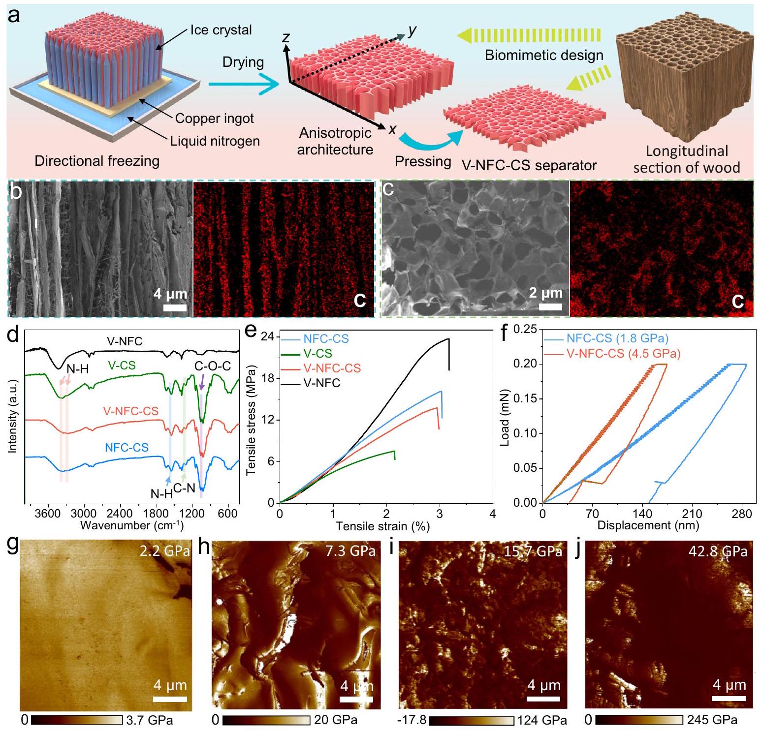
كما هو موضح في الشكل 1a، تتضمن عملية تصنيع فاصل V-NFC-CS تقنية التجميد الاتجاهي، حيث تم صب مزيج من التعليق المائي الذي يتكون من NFC والكيتوزان على السطح العلوي لقطعة نحاسية. تم غمر الجزء السفلي من القطعة في حمام من النيتروجين السائل. يمكن أن يسهل هذا الترتيب النمو العمودي لبلورات الثلج على طول-محور بسبب تعرض قضيب النحاس للنيتروجين السائل. وبالتالي، ستتعرض الأجزاء غير المتجمدة، التي تشمل مكونات الكيتوزان وNFC، للضغط. ستؤدي عملية تبخر بلورات الثلج عبر التجفيف بالتجميد إلى إنتاج قنوات مصفوفة عمودياً، مما ينتج عنه تكوين معماري غير متساوي.. من المثير للاهتمام أن هذه العمارة تشبه بشكل لافت المقطع الطولي للخشب، حيث أن معامل المرونة على طول -المحور يتجاوز ذلك الخاص بالمحاور الأخرى. علاوة على ذلك، وبالمثل للظواهر السريعة للنقل التي لوحظت داخل قنوات الخشب للماء، والأملاح غير العضوية، والمواد المغذية العضوية، يمكن أن يظهر الفاصل غير المتجانس هنا خصائص مماثلة. بالإضافة إلى ذلك، فإن الضغط المطبق البالغ 50 بار على طول الـ-المحور يمكن أن يعزز بشكل أكبر معامل المرونة في ذلك الاتجاه. التعيينات للمنتجات التي تم الحصول عليها، المشار إليها باسم V-NFC-CS ( ), V-NFC-CS ( )، و V-NFC-CS ( )، تتوافق مع نسب الكتلة المت varying من الكيتوزان إلى NFC بنسبة 1:10 و 2:10 و 3:10، على التوالي. يُلاحظ أنه ما لم يُذكر خلاف ذلك، فإن V-NFCCS تشير إلى نسبة كتلة للكيتوزان.
تم تلخيص التقنيات المبلغ عنها المستخدمة في تصنيع الفواصل لبطاريات AZIBs في الجدول التكميلي 1. قامت بعض الدراسات السابقة بتعديل الفواصل التجارية مثل فواصل GF، في حين أن العيوب الجوهرية لفواصل GF (أي، السعر المرتفع حوالي 500 دولار أمريكي)وسماكة مفرطة لا تقل عنتظل مشكلة. بالإضافة إلى ذلك، فإن طرق التصنيع الشائعة مثل الترشيح تحت الفراغ والتقنية الكهربائية ليست مناسبة بشكل جيد للإنتاج السريع للفواصل. في هذه الدراسة، تم استخدام تقنية التجميد الاتجاهي القابلة للتوسع والتي يمكنها الإنتاج السريع لتصنيع فاصل V-NFCCS. كما هو موضح في الشكل التوضيحي 1، يمكن بسهولة توسيع حجم فاصل V-NFCCS إلى. استنادًا إلى تكاليف المواد الخام على نطاق الكيلوغرام (الكيتوزان: دولار أمريكيمساحيق خشب البلسا: دولار أمريكي، مقدر منعلي بابا.كوم) ويفترض أن تكاليف التصنيع تمثل من إجمالي التكلفة، التكلفة المقدرة لفاصل V-NFC-CS هي دولار أمريكيمن المتوقع أن تنخفض هذه التكلفة بشكل كبير عند زيادة مقاييس الإنتاج. ومع ذلك، عند الانتقال إلى الإنتاج الصناعي، ستتطلب طريقة التجميد الاتجاهي المستخدمة في هذا العمل إعادة تصميم وتخطيط المعدات وخطوط الإنتاج، حيث لا يمكن استخدام الإعدادات الحالية مباشرة. ومع ذلك، يجب ألا يشكل هذا تحديًا كبيرًا للفنيين في هذا المجال.
فاصل أرق مفيد لتحسين كثافة طاقة البطارية. كما هو موضح في الشكل التوضيحي 2، فإن فاصل V-NFC-CS يتمتع بسماكة منخفضة من، وهو ما يقل بشكل كبير عن معظم الفواصل المصممة لـ AZIBs، مثل تلك المدرجة في الجدول التكميلي 1. ومع ذلك، من المتوقع أن يتم تقليل سمك فاصل V-NFC-CS في جهود البحث المستقبلية، بهدف تحقيق سمك مثالي منخصائص البنية المجهرية لمختلف الفواصل في و تمت دراسة الطائرات (انظر الشكل 1أ لتعريف المحاور) باستخدام المجهر الإلكتروني الماسح (SEM). ضمنفي المستوى، يظهر فاصل V-NFCCS ترتيبًا ملحوظًا من القنوات المتجانسة والمتوازية (الشكل 1ب والأشكال التكميلية 3أ، ب، و4أ)، بالتزامن مع وجود وفير من المسام (نهايات القنوات) فيطائرة (الشكل 1 ج والشكل التكميلي 3 ج، د). كما لوحظ أنه يوجد
الشكل 1 | إعداد وتوصيف فاصل V-NFC-CS. أ رسم تخطيطي لإجراء إعداد فاصل V-NFC-CS. صور SEM وصور رسم خرائط EDX المقابلة لفاصل V-NFC-CS:في الـطائرةفيطائرة. طيف FTIR ومنحنيات الإجهاد والانفعال الشدّي لفواصل V-NFC و V-CS و V-NFC-CS و NFC-CS. منحنيات القوة والإزاحة لـ NFC-CS و V-NFC-
فواصل CS. توزيعات معامل DMT لـفاصل NFC-CS وفاصل V-NFC-CS. توزيعات معامل DMT لأقطاب الزنك بعد عملية طلاء الزنكباستخدام تكوين خلية العملة وفاصل V-NFC-CS و j باستخدام تكوين خلية إلكتروليتية بدون أي فاصل. بعض الألياف داخل قنوات فاصل V-NFC-CS (الشكل التكميلي 4b). تُنسب هذه الألياف إلى NFC، التي تتواجد في القنوات بسبب قدرتها الجيدة على الترطيب. بشكل محدد، تفشل عملية تجميد الماء في طرد NFC بالكامل من بلورات الجليد بسبب التفاعل القوي بين الماء وNFC، مما يترك جزءًا من NFC في القنوات. لتسليط الضوء على فوائد الهيكل غير المتجانس، تم استخدام طريقة تجميد تقليدية (أي التجميد في الثلاجة) لصنع فاصل مركب غير متجانس من NFC/كيتوزان يُشار إليه باسم NFC-CS. يكشف فحص هذا الفاصل عن عدم وجود فرق واضح بين و الطائرات (الشكل التوضيحي 5a، b)، مؤكدة غياب الخصائص غير المتجانسة لفاصل NFC-CS. من أجل مقارنة أفضل، تم استخدام عملية التحضير تقريبًا بنفس طريقة فاصل V-NFC-CS لتحضير فاصل V-CS وV-NFC، والتي تتكون فقط من الكيتوزان وNFC، على التوالي. من الواضح أن فاصل V-CS يمتلك أيضًا بنية غير متجانسة (الشكل التوضيحي 5c، d)، بينما يفتقر فاصل V-NFC إلى هذه السمة الهيكلية بسبب التأثير المحب للماء المذكور أعلاه (الشكل التوضيحي 5e، f). لتوضيح الدور الحاسم بشكل أكبر في عملية التجميد الاتجاهي لتشكيل الهياكل غير المتجانسة، تم استخدام طريقة تجميد تقليدية لتحضير فواصل CS و NFC. كما هو موضح في صور SEM في الشكل التكميلية 6، تفشل هذه الطريقة التقليدية في إنتاج الهيكل غير المتجانس، مما يبرز ضرورة التجميد الاتجاهي لتحقيق المحاذاة المطلوبة.
تمت دراسة خصائص التبلور لأربعة فواصل مختلفة من خلال تحليل حيود الأشعة السينية (XRD) (الشكل التكميلي 7). كان واضحًا في أنماط XRD وجود قمة عريضة عنديتوافق مع السليلوز وقمة مميزة عنددليل على الكيتوزان. تم استخدام مطيافية الأشعة تحت الحمراء بتحويل فورييه (FTIR) للكشف عن المجموعات الوظيفية داخل هذه الفواصل (الشكل 1d). كانت الحزم المميزة عند 3284 وتنشأ من مجموعة الأمين، والأشرطة عند 1540، 1312، ويأتي مناهتزاز التمدد،رابطة، والرابطة، على التواليلقد أكدت الدراسات السابقة أن هذه الروابط الكيميائية تقيدالنشاط، تسهيل عملية إزالة الذوبان، وتجانستدفق الأيونات، وبالتالي تعزيز ترسيب الزنك بشكل موحد.
تدعم هذه الملاحظات أيضًا دمج الكيتوزان وNFC في فاصل V-NFC-CS. قوة الشد العرضية لفواصل مختلفة على طول-محور أو تم تقييم اتجاه المحور – (الشكل 1e). في هذا الصدد، يظهر فاصل V-NFC أكبر قوة تبلغ 23.8 ميغاباسكال، مستفيدًا من الخصائص الميكانيكية الجيدة لـيُعزز تأثير التعزيز لـ NFC بشكل كبير من قوة فاصل V-NFC-CS (13.8 ميجا باسكال) مقارنة بفاصل V-CS.كما وُجد أن قوة فاصل V-NFC-CS هيأقل من تلك الخاصة بفاصل NFC-CS، مما يشير إلى تضحيات في القوة على طول الاتجاه غير الموجه بسبب الهيكل غير المتجانس، وإن كان ذلك ليس إلى حد كبير.
تقييم المودولوس والتوصيلية الأيونية
كما تم مناقشته سابقًا، فإن الخصائص الميكانيكية على طولاتجاه المحور – له أهمية أكبر. تم إجراء قياسات النانو-indent لتStudying هذه الخصائص (الشكل 1f). يظهر فاصل V-NFC-CS معامل يونغ والصلابة بقيمة 4.5 و 0.44 جيجا باسكال، على التوالي، وكلاهما متفوق بشكل ملحوظ على فاصل NFC-CS (1.8 و 0.16 جيجا باسكال، على التوالي). ومن الجدير بالذكر أن معامل فاصل V-NFC-CS أكبر بكثير من ذلك الخاص بفاصل VVLP المبلغ عنه سابقًا (45.8 ميجا باسكال) لبطاريات AZIBs وتلك الفواصل التي تتميز بمعامل عالٍ لبطاريات LMBs.تم استخدام تقنية المجهر الذري القوي (AFM) لتوضيح الفجوة في معامل المرونة، كما هو موضح في الشكل 1g، h والشكل التكميلي 8a، b. متوسط معامل ديرجاكين-مولر-توبوروف (DMT) لفاصل V-NFC-CS هو 3.3 مرة من فصل NFC-CS (2.2 جيجا باسكال). لتسليط الضوء بشكل أفضل على أهمية معامل الفصل، تم تقييم معامل أقطاب الزنك أيضًا (الشكل 1i، j والشكل التكميلي 8c، d). بعد عملية طلاء الزنك لـلمدة ساعة واحدة، يصل متوسط معامل الزنك في الأقطاب ضمن خلايا العملة إلى قيمة كبيرة تبلغ 15.7 جيجا باسكال مع استخدام فاصل V-NFC-CS. عندما يتم استخدام تكوين خلية إلكتروليتية في غياب أي فاصل، يكون متوسط المعامل أكبر حتى يصل إلى 42.8 جيجا باسكال. تكشف هذه النتائج عن الآثار الضرورية والمفيدة لتعزيز معامل الفاصل لبطاريات AZIBs.
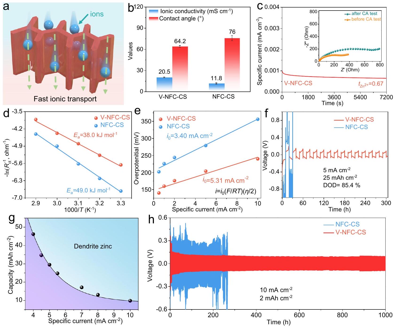
يمكن أن تُدخل البنية غير المتجانسة لفاصل V-NFC-CS قنوات موجهة مصفوفة على طول-محور. يتضح ذلك من اختبارات إضاءة الصمام الثنائي الباعث للضوء (LED) المعروضة في الشكل التوضيحي 9. عندما يتم وضع مصباح LED تحت طائرة مع الضوء موجه بشكل رئيسي على طول-المحور، يمكن لمعظم الضوء أن يخترق بشكل فعال فاصل V-NFC-CS، في حين أن انتقال الضوء من خلال فاصل NFC-CS يتناقص بشكل كبير. يمكن أن تسهل القنوات الموجهة عمودياً داخل فاصل V-NFC-CS انخفاض التعقيد في نقل الأيونات.كما هو موضح في الشكل 2أ. على النقيض الحاد، فإن الهيكل المسامي غير المنظم لفاصل NFC-CS يؤدي إلى مسارات معقدة لنقل الأيونات (الشكل التكميلي 10). للتحقق من ذلك، تم قياس الموصلية الأيونية لأربعة فواصل مختلفة على طولتم تقييم اتجاه المحور – من خلال قياسات طيف الامتياز الكهربائي (EIS) (الشكل التكميلي 11a)بفضل الهيكل غير المتجانس في فاصل V-NFC-CS، فإن موصلية الأيونات الخاصة بهيتجاوز بشكل كبير أداء فاصل NFC-CS ) وفاصل V-NFC ( )، كما هو موضح في الشكل 2b والشكل التكميلي 11b. بالإضافة إلى ذلك، فإن الموصلية الأيونية لفاصل V-NFC-CS أقل من تلك الخاصة بفاصل V-CS ( )، يُعزى ذلك إلى وجود NFC داخل قنوات السابقة. على الرغم من ذلك، فإن الفرق في الموصلية الأيونية بين هذين الفاصلين صغير جداً. تم أيضاً فحص فواصل NFC وCS التي تم إعدادها بطريقة التجميد التقليدية، كما هو موضح في الشكل التكميلي 12. وبدون قنوات موجهة، تظهر موصلية أيونية منخفضة تبلغ 10.5 وعلى التوالي، مما يعزز بشكل أكبر الدور الهام للبنية غير المتجانسة في تعزيز النقل الأيوني على طول-اتجاه المحور.
تم رسم قيم الموصلية الأيونية المعتمدة على درجة الحرارة لفواصل V-NFCCS و NFC-CS، استنادًا إلى قياسات EIS عند درجات حرارة مختلفة (الشكل التكميلي 13a، b) في
الشكل التكميلي 13c. وفقًا لنتائج التناسب من خلال معادلة أرهينيوس، فإن طاقة تنشيط التوصيل الأيوني داخل فاصل V-NFC-CS تبلغ فقط 0.061 إلكترون فولت، والتي هيأقل من ذلك داخل فاصل NFC-CS. هذا يؤكد أن النقل الأيوني أكثر كفاءة بشكل ملحوظ على طول-المحور في وجود قنوات موجهة. لتقييم خصائص التبلل لمختلف الفواصل بالنسبة إلىتم إجراء اختبارات زاوية الاتصال (الشكل التكميلي 14) باستخدام الإلكتروليت المائي. نظرًا لتحسن خاصية المحبة للماء بشكل ملحوظ في NFC مقارنة بالكيتوزان، فإن الفاصل V-NFC يظهر أدنى زاوية اتصال.عندما تم إسقاط الإلكتروليت للتو، بينما يظهر فاصل V-CS أعلى زاوية تماس.بعد مدة قدرها 30 ثانية، تنخفض زوايا الاتصال لفواصل V-NFC-CS و V-NFC إلى، بسبب القنوات الرأسية داخل المادة السابقة التي يمكن أن تسمح للماء بالتغلغل بسرعة ووجود خاصية محبة للماء جيدة في NFC. وعلى العكس، بسبب انخفاض خاصية المحبة للماء نسبيًا في الكيتوزان، يبقى زاوية الاتصال لفاصل V-CS قيمة كبيرة من بعد 30 ثانية. أما بالنسبة لفاصل NFC-CS، الذي يتميز بغياب القنوات الرأسية ووجود الكيتوزان، فإن زاوية الاتصال تبقى تقريبًا دون تغيير بعد 30 ثانية. إن زيادة قابلية البلل لـ V-NFC-CS تسهم في وصول الإلكتروليت المائي.
تحقيق حولخلايا
بعد 7 أيام من التخزين فيقبل أي اختبار كيميائي كهربائي، تم إخراج الأقطاب الزنك لإجراء قياسات XRD (الشكل التكميلي 15). لا يمكن الكشف عن أي إشارات تقريبًا بخلاف تلك الخاصة بالزنك المعدني عند استخدام فاصل V-NFC-CS. ومع ذلك، هناك قمة حيود واضحة عند حوالييظهر عند استخدام فاصل NFC-CS أو GF. هذه القمة تتوافق مع مستوى (001) من، الذي يتكون نتيجة تآكل معدن الزنك. تشير هذه النتائج إلى أن فاصل V-NFC-CS يمكنه بفعالية كبح مشكلة تآكل قطب الزنك. وفقًا لمنحنيات الكرونوأمبرو متري (CA) والرسوم البيانية لنيوكويست المقابلة لـ Znخلايا بفواصل مختلفة،رقم نقل الأيونيمكن تحديدهكما هو موضح في الشكل 2c والشكل التكميلي 16.مع فاصل V-NFC-CS (0.67) يتجاوز بشكل كبير ما تم الحصول عليه مع فاصل NFC-CS (0.51). تنشأ هذه الفجوة من عاملين رئيسيين. من ناحية، الحجم الكبير نسبيًا لأيون الزنك المائيفي القطر) يجعل نقله عرضة للاعتراض من قبل إطار الفاصل. وبالتالي، فإن الاعتراض الذي يتم مواجهته في فاصل NFC-CS، الذي يحتوي على مسارات نقل أيونية أطول، أكبر من ذلك في فاصل V-NFC-CS، الذي يتميز بقنوات موجهة. من ناحية أخرى، تظهر تشتتات NFC والكيتوزان قيم جهد زتا تبلغ -31.4 و26.7 مللي فولت، على التوالي. الشحنة السلبية لـ NFC تسهلنقل الأيونات، بينما الشحنة الموجبة للكيتوزان تعيق ذلك. من خلال دمج النتائج من الأشكال التكميلية 12 و 17، يتضح أنموصلية الأيونات عبر فاصل NFC هيأعلى من ذلك من خلال فاصل CS. في سياق استخدام فاصل V-NFC-CS،يحدث نقل الأيونات بشكل أساسي من خلال القنوات الرأسية، حيث يتواجد NFC ويكون الكيتوزان غائبًا، مما يسهم في تحسيننقل الأيونات. تم إجراء اختبارات EIS أيضًا علىالخلايا عند درجات حرارة مختلفة تتراوح من 30 إلى (الشكل التوضيحي 18). استنادًا إلى هذه النتائج، فإن طاقة تنشيط إزالة الحلول (يمكن تقديره (الشكل 2د). من الواضح أن المرتبطة باستخدام فاصل V-NFC-CS (أقل من ذلك باستخدام فاصل NFCCS )، مما يشير إلى أن الأول يمكن أن يعزز بشكل فعال عملية إزالة الترطيب للـالأيونات، مما يعزز من حركية الطلاء بالزنك ويمنع التفاعلات الجانبية الناتجة عن الماء.
تم استكشاف تأثير الفاصل على سلوك الطلاء/إزالة الطلاء بالزنك من خلال قياسات الشحن/التفريغ الجلفاني.. كما هو موضح في الشكل التكميلي 19، الـتظهر الخلية مع فاصل V-NFC-CS انخفاضًا في تذبذب الجهد يتراوح من 100 إلى 240 مللي فولت مع زيادة التيار المحدد من 0.5 إلى
الشكل 2 | خصائص فاصل V-NFC-CS والأداء الكهروكيميائي لـالخلايا. أ رسم توضيحي لمسار النقل الأيوني السريع داخل فاصل V-NFC-CS. ب زاوية الاتصال والموصلية الأيونية لفواصل V-NFC-CS و NFC-CS (تمثل أشرطة الخطأ الانحراف المعياري المحسوب من خمسة اختبارات متوازية). ج منحنى CA لخلية Zn||Zn مع فاصل V-NFC-CS ومخططات نايكويست المقابلة لتحديدمنحنيات أرهينيوس المحسوبةالقيم باستخدام فصلين مختلفين. قيم الجهد الزائد بالنسبة للتيار المحدد والقيم وملفات GCD في و منالخلايا عند استخدام فاصلين مختلفين.سعة الرمل المعتمدة على التيار باستخدام فاصل V-NFC-CS. ملفات GCD لخلايا Zn ||Zn مع فاصلين مختلفين في و . “، بالمقارنة مع استخدام فاصل NFC-CS (من 180 إلى 364 مللي فولت). وفقًا لهذه القيم الزائدة في الجهد، فإن كثافة التيار المتبادل (يمكن حسابه (الشكل 2e)يمكن رؤية ذلك بوضوح أن يتحسن مع استخدام فاصل V-NFC-CS، مما يدل على تحسين الديناميات الكهروكيميائية. إن استقرار الدورة على المدى الطويل لـ تم تقييم الخلايا ذات الفواصل المختلفة عند تيار محدد قدرهوسعة سطحية قدرها (الشكل التوضيحي التكميلي 20). مقارنةً بـ V-NFC-CS ( ) و V-NFC-CS ( فواصل )، V-NFC-CS (يظهر الفاصل ) أداءً أفضل، مع عمر افتراضي يتجاوز 2000 ساعة. وعلى النقيض الحاد، فإن الزنكيمكن تشغيل الخلايا التي تحتوي على فواصل NFC-CS و V-NFC بشكل مستقر لمدة تقارب 500 و 360 ساعة، على التوالي. أما بالنسبة لاستخدام فاصل V-CS، فإن الجهد الزائد كبير إلى حد ما ويتقلب جهد الخلية بشكل كبير، مما يشير إلى فشل الخلية..
لفحص جدوى استخدام فاصل V-NFC-CS تحت ظروف قاسية، تم تجميعتم تشغيل الخلية عندوسعة هائلة في المساحة، مما يتوافق مع عمق تفريغ هائل (DOD) من (الشكل 2f). تحت هذه الظروف، تفشل الخلية التي تحتوي على فاصل NFC-CS خلال الدورة الأولية. في الضرب في المقابل، الخلية التي تحتوي على فاصل V-NFC-CS مستقرة لمدة لا تقل عن 300 ساعة. علاوة على ذلك، تم تقييم سعة الرمل، المحددة كنقطة بدء تكوين الدندريتات الشديدة، تحت تيارات محددة مختلفة (الشكل التكميلي 21، الشكل 2g مع المنطقة الزرقاء الفاتحة التي تشير إلى الدندريتات الشديدة).ليس من المستغرب أن تنخفض سعة الرمل مع زيادة التيار المحدد. ومع ذلك، لا تزال سعة الرمل تصل إلىعند تيار محدد كبيرتحت شرط و ، الـيمكن أن توفر الخلية التي تحتوي على فاصل V-NFC-CS تشغيلًا مستقرًا لأكثر من 1000 ساعة (الشكل 2h). بالمقابل، تعاني الخلية التي تحتوي على فاصل NFC-CS من زيادة كبيرة في الجهد وتقلبات دراماتيكية في الجهد. تؤكد هذه الفجوة التأثير الإيجابي للهندسة غير المتجانسة للفاصل على استقرار واجهة الزنك/الإلكتروليت. بالإضافة إلى ذلك، فإن الاستقرار الكهروكيميائي عند استخدام فاصل V-NFC-CS يتفوق بشكل كبير على ذلك باستخدام فاصل GF التقليدي (الشكل التكميلية 22). كما هو موضح في الشكل التكميلية 23 والجدول التكميلية 1، فإن عمر الخدمة والسعة التراكمية المقابلة لترسيب الزنك لـ Znالخلايا التي تحتوي على فاصل V-NFC-CS في هذا العمل تتفوق على تلك التي تستخدم فواصل أخرى، مثل
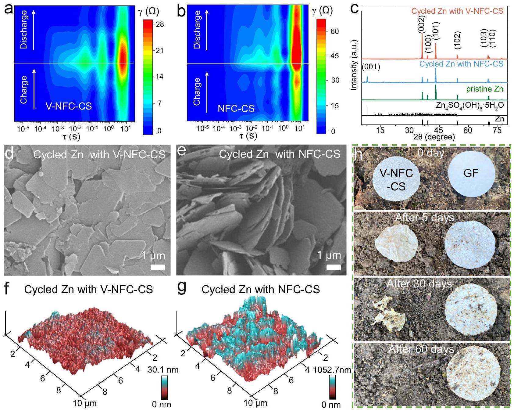
الشكل 3 | تقييم قابلية عكس إزالة/تغطية الزنك وقابلية تحلل الفاصل الحيوي. ملفات تعريف DRT لـالخلايا خلال عملية GCD في الدورة الرابعة: أ مع فاصل V-NFC-CS ومع فاصل NFC-CS.أنماط XRD لقطب الزنك النقي وأقطاب الزنك بعد القياسات في الشكل 2h. د، هـ SEM صور وصور AFM لأقطاب الزنك بعد القياسات في الشكل 2h:مع فاصل V-NFC-CS ومع فاصل NFC-CS. صور لفواصل V-NFC-CS و GF بعد أن تم دفنها في التربة لفترات زمنية مختلفة. فاصل زيوتي مصفوف من البوليمر (SZ)فاصل السليلوز السلفوني (CF-SO3)وغشاء غربال جزيئي.
قابلية عكس إزالة/تغطية الزنك
تم استخدام اختبارات EIS في الموقع لتقييم تغيرات المقاومةالخلايا خلال الدورة الرابعة (الشكل التكميلي 24). تم تحويل مخططات نايكويست المكتسبة بعد ذلك إلى توزيعات زمن الاسترخاء (DRT)، كما هو موضح في الشكل 3a، b. الإشارات الملاحظة على مقياس الزمن لـ تتعلق بمقاومة نقل الشحنة ( )، بينما يمكن أن تُعزى تلك التي تتجاوز 1 ثانية إلى مقاومة الانتشار لـ الأيونات داخل قطب ترسيب الزنكباستخدام فاصل V-NFC-CS، يمكن تقليل قيم المقاومة، كما يمكن تعزيز قابلية إزالة/طلاء الزنك بشكل كبير، مقارنةً بتلك التي تستخدم فاصل NFC-CS. للحصول على رؤى أعمق حول قابلية إزالة/طلاء الزنك، تم إجراء قياسات XRD على أقطاب الزنك بعد عدد متنوع من الدورات فيالخلايا التي تعمل عند و (الشكل 3c والشكل التكميلية 25). من الواضح أن قمة (001) لمنتج ZSH الثانوي عند القطب الزنك بعد الدورة مع فاصل V-NFC-CS أضعف بكثير من تلك مع فاصل NFC-CS. يرتبط تكوين ZSH ارتباطًا وثيقًا بتفاعل تطور الهيدروجين، الذي يزيد من التركيز المحلي لـقرب سطح القطب الزنك. إلى تقييم تطور الهيدروجين، سمكتمت مقارنة الخلايا قبل وبعد القياسات في الشكل 2h (الشكل التكميلي 26). يمكن ملاحظة أن معدل توسع السماكة باستخدام فاصل V-NFCCS هو مجردأقل بكثير من الـ و تمت ملاحظته مع فواصل NFC-CS و GF، على التوالي. لتقييم تطور الهيدروجين بشكل أفضل، تم قياس تغيرات السماكة لنوع الحقيبةالخلايا (أبعاد الأقطاب الكهربائية: ) تم قياسها بعد ركوب الدراجة في و لمدة 60 ساعة، كما هو موضح في الشكل التوضيحي 27. عند استخدام فاصل GF، يظهر سمك الخلية زيادة كبيرة قدرها 3.89 مم، مما يتوافق مع توسع في الحجم تُعزى هذه التغيرات في الحجم بشكل أساسي إلى تطور الهيدروجين. في حالة استخدام فاصل NFC-CS، ينخفض مقدار تطور الهيدروجين، على الرغم من أنه لا يزال كبيرًا نسبيًا. بالمقابل، مع استخدام فاصل V-NFC-CS، يتم تقليل زيادة سمك الخلية بشكل كبير. تُظهر هذه النتائج أن فاصل V-NFC-CS يمكن أن يثبط بشكل فعال تطور الهيدروجين.
بالإضافة إلى ذلك، مع زيادة عدد الدورات، تزداد نسبة شدة الحيود لقمة Zn (002) إلى قمة Zn (101) تدريجياً عند استخدام فاصل V-NFC-CS، في حين أن هذه النسبة تنخفض مع استخدام فاصل NFC-CS. حيث أن اتجاهات ترسيب الزنك على المستويات (002) و (101) تت correspond إلى سلوكيات النمو الأفقية والعمودية، على التوالي.يمكن استنتاج أن V-NFC-CS يمتلك الفاصل تأثيرًا مفيدًا في تعزيز ترسيب الزنك الأفقي. لتأكيد الملاحظات المذكورة أعلاه، تم استخدام SEM لفحص مورفولوجيا سطح أقطاب الزنك بعد القياسات في الشكل 2h، كما هو موضح في الشكل 3d وe والشكل التكميلي 28. يؤدي استخدام فاصل V-NFC-CS إلى سطح أقطاب زنك مستوٍ خالٍ من تشكيل الدندريت بعد الدورة، بينما تُلاحظ بروزات واضحة على سطح قطب الزنك مع فاصل NFC-CS. تشكل هذه البروزات خطرًا على ثقب الفاصل، مما يؤدي بسهولة إلى سلسلة من المشكلات مثل الدائرة القصيرة. تم استخدام تقنية AFM أيضًا لمراقبة الخصائص السطحية لأقطاب الزنك المدورة، مما يكشف أن خشونة سطح قطب الزنك مع فاصل V-NFC-CS أقل بكثير من تلك مع فاصل NFC-CS (الشكل 3f وg). تنبع هذه الفروق بشكل أساسي من تأثير التثبيط لفاصل V-NFC-CS عالي الصلابة ضد الترسيب العمودي لمعدن الزنك وتكوين منتج ZSH الثانوي المحتمل.
تم إجراء الاختبارات الكهروكيميائية السابقة فيلزيادة التحقق من فعالية فاصل V-NFC-CS، تم تقييم أداء الدورة لـتم تقييم الخلايا عند درجات حرارة مرتفعة. كما هو موضح في الشكل التوضيحي 29a، عند، يتم تقصير عمر خلايا التي تستخدم فواصل مختلفة بشكل ملحوظ إلىفي و . على الرغم من ذلك، فإن استخدام فاصل V-NFC-CS لا يزال يوفر أفضل استقرار. بعد 16 ساعة من الاختبار، تعاني جميع خلايا العملة التي تستخدم فواصل مختلفة من انتفاخ شديد مصحوب بتصدع الخلايا (الشكل التكميلي 29ب)، وتظهر أقطاب الزنك المعدنية المدورة سطحًا خشنًا وقمم حيود شديدة تُنسب إلى ZSH (الشكل التكميلي 29ج، د)، مما يدل على تطور هيدروجين ملحوظ في عندما تكون درجة حرارة الاختبار (الشكل التوضيحي التكميلي 29e)، فإن استقرار الدورة للخلايا أفضل بكثير من ذلك في بين ثلاثة أنواع من الخلايا، يحقق استخدام فاصل V-NFC-CS أطول عمر افتراضي يبلغ 1000 ساعة فيبالإضافة إلى ذلك، تم تضمين فاصل V-NFC-CS وفاصل GF في التربة لتقييم القابلية للتحلل البيولوجي. يحتفظ فاصل GF بشكله السليم بعد 60 يومًا (الشكل 3h). على النقيض من ذلك، يختفي فاصل V-NFC-CS بسبب التحلل الكامل، مما يكشف أن هذا الفاصل يمتلك خصائص قابلة للتحلل البيولوجي وصديقة للبيئة.يجب ملاحظة أن التحلل السريع لفاصل V-NFC-CS يحدث في التربة، وليس في الإلكتروليت، حيث توفر التربة ظروفًا أكثر مثالية (مثل وجود مجتمع ميكروبي غني) لتحلل المواد الحيوية. يمكن تأكيد ذلك من خلال حقيقة أنه لا يوجد تغيير واضح لفاصل V-NFC-CS بعد 60 يومًا من الغمر فيالالكتروليت المائي (الشكل التكميلي 30). بالإضافة إلى ذلك، يمكن الحفاظ على الهيكل غير المتجانس لفاصل V-NFC-CS بعد القياس الكهروكيميائي (الشكل التكميلي 31). كما هو موضح في الشكل التكميلي 32، لا تزال الروابط الكيميائية داخل فاصل V-NFC-CS موجودة بعد القياس في الشكل 2h.
محاكاة العناصر المحدودة
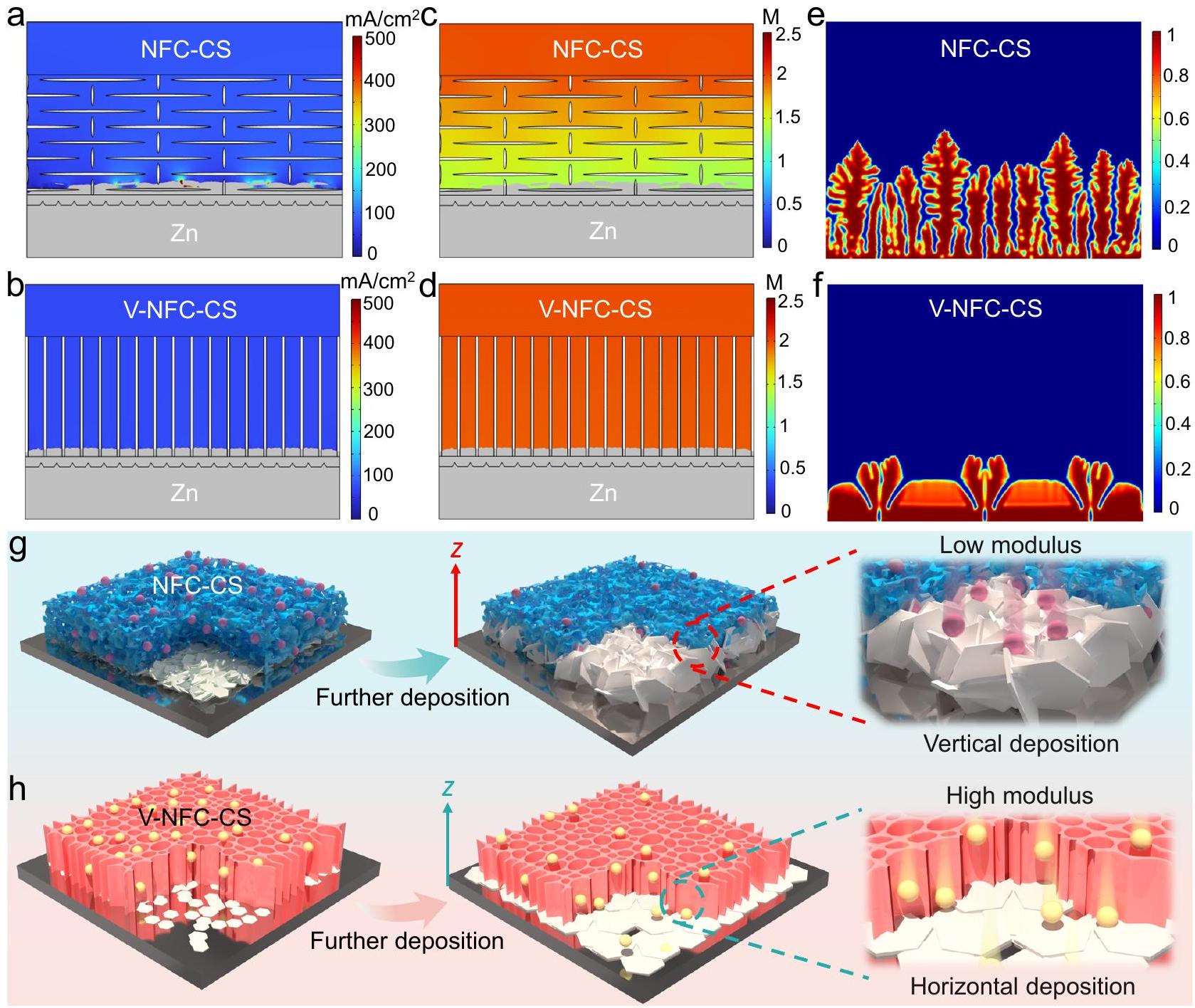
تم إجراء محاكاة العناصر المحدودة باستخدام برنامج COMSOL لفهم دور الفاصل غير المتجانس بشكل أفضل. تكشف النتائج، الموضحة في الشكل 4a و4b، الشكل التكميلي 33، والفيلم التكميلي 1، أن مجال كثافة التيار مع تنفيذ فاصل V-NFC-CS أكثر تجانسًا في المواقع المحلية القريبة من سطح الزنك المعدني المودع مقارنةً باستخدام فاصل NFC-CS.تمت محاكاة توزيعات تركيز الأيونات أيضًا، كما هو موضح في الشكل 4c و4d، الشكل التكميلي 34، والفيلم التكميلي 2. من الواضح أن استخدام فاصل V-NFC-CS يساهم في تركيز أعلى بشكل ملحوظ منأيونات على سطح معدن الزنك المودع، جنبًا إلى جنب مع مزيد من التوزيع المتجانستوزيع الأيونات على طولاتجاه المحور -، مقارنة باستخدام فاصل NFC-CS. هذه الفوائد مستمدة بشكل أساسي من الهندسة المعمارية الفريدة لفاصل V-NFC-CS، الذي يعزز بشكل فعال نقلأيونات على طول-اتجاه المحور. في الوقت نفسه، يظهر الزنك المعدني المودع باستخدام فاصل V-NFC-CS مورفولوجيا أكثر انتظامًا بكثير مقارنةً بتلك التي تستخدم فاصل NFC-CS. إلى لفهم تأثير الخصائص الميكانيكية للفاصل على شكل معدن الزنك المترسب، تم إنشاء نموذج ميكانيكي كهربائي لمحاكاة أشكال طلاء الزنك باستخدام فاصلين مختلفين، كما هو موضح في الشكل 4e و f، الشكل التكميلي 35، والفيلم التكميلي 3. من الواضح أن معدن الزنك يفضل أن يتم ترسيبه عموديًا عند استخدام فاصل NFC-CS. لحسن الحظ، يمكن تقليل هذه الميل نحو ترسيب الزنك العمودي بشكل كبير عند استخدام فاصل V-NFC-CS.
استنادًا إلى النتائج في الأقسام السابقة، يتم توضيح أشكال ترسيب الزنك في الشكل 4g و h. مصحوبةً بحقل كثافة التيار غير المتساوي وتوزيع تركيز الأيونات على سطح قطب معدن الزنك باستخدام فاصل NFC-CSتميل الأيونات إلى الهجرة نحو البروزات النقية ومواقع النواة الموجودة، مما يؤدي إلى ترسيب الزنك عمودياً. بسبب معامل المرونة المنخفض لفاصل NFC-CS، سيتطور الزنك المعدني المترسب عمودياً إلى نمو شجيري شديد، مما سيزيد من ردود الفعل الطفيلية مثل تكوين ZSH. على العكس من ذلك، يمكن تجنب هذه الآثار غير المرغوب فيها من خلال استخدام فاصل V-NFC-CS. من ناحية، فإن معامل المرونة العالي لفاصل V-NFC-CS على طوليمكن أن تقاوم اتجاه محور – بشكل فعال الاتجاه العمودي لنمو معدن الزنك ومنتج ZSH الثانوي. من ناحية أخرى، سريعيمكن أن يخفف نقل الأيونات على طول القنوات الرأسية الموجهة لفاصل V-NFC-CSتثبيط تركز أيونات القطبية عند سطح إلكترود معدن الزنك، مما يقلل من تفاعل تطور الهيدروجين. تنشأ هذه الفوائد لفاصل V-NFC-CS في كلا الجانبين من الهيكل غير المتجانس، والذي من المتوقع أن يكون مفيدًا في أنظمة البطاريات الأخرى أيضًا.
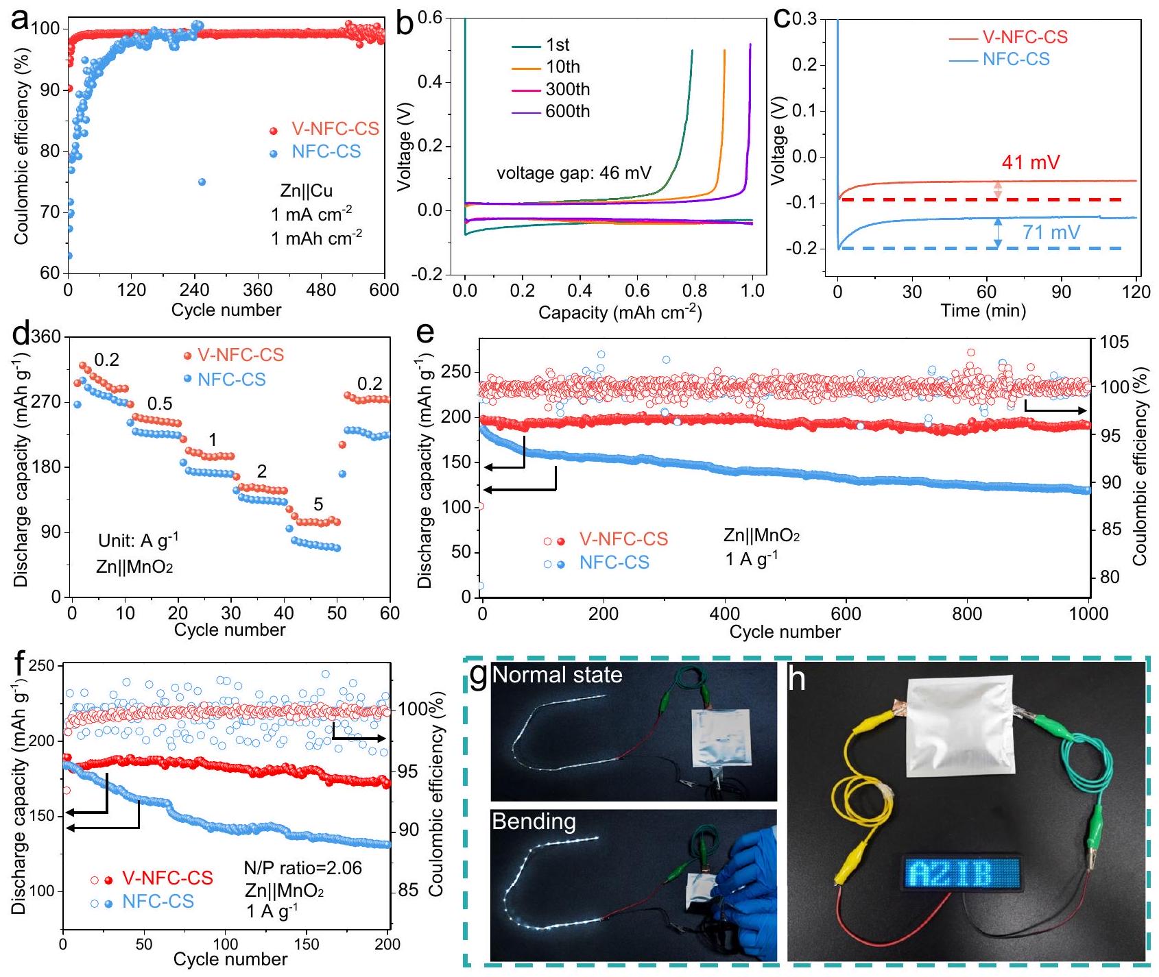
العامل الحاسم لتحقيق بطاريات AZIBs عالية المتانة يكمن في القابلية العالية للعكس لعملية إزالة الطلاء/الطلاء بالزنك. لتقييم هذا الجانب،تم إخضاع خلايا النحاس التي تحتوي على V-NFC-CS أو فاصل NFC-CS لاختبار كفاءة كولوم (CE)، بهدف تمييز تأثيرها على قابلية عكس الأقطاب السلبية من الزنك.كما هو موضح في الشكل 5a، فإن CE الأولي مع فاصل V-NFC-CS يبلغ، ثم يستقر CE عندمن الدورة العشرين إلى الدورة السادسة مئة. بالمقابل، فإن استخدام فاصل NFC-CS يؤدي إلى انخفاض كبير في الكفاءة الأولية لـ، مع ظهور مشكلة الدائرة القصيرة قبل 255 دورة. ومن الجدير بالذكر أن عمر خلية مع فاصل V-NFC-CS (1200 ساعة) أطول من ذلكالخلايا ذات الفواصل المختلفة في التقارير السابقة، كما هو موضح في الجدول التكميلي 2. في الوقت نفسه،تظهر الخلية التي تستخدم فاصل V-NFC-CS فجوة جهد مخفضة (46 مللي فولت، بين هضاب الشحن والتفريغ، الشكل 5b)، مقارنة بتلك التي تستخدم فاصل NFC-CS (148 مللي فولت، الشكل التكميلية 36)، مما يشير إلى أن الديناميات الكهروكيميائية يمكن تحسينها بشكل كبير بواسطة فاصل V-NFC-CS.من خلال تحليل منحنيات الجهد-السعة الأولية لـيمكن تقدير قيم جهد النواة في الخلايا (الشكل 5c). هذه القيمة تساوي 41 مللي فولت لفاصل V-NFC-CS، وهو أقل بكثير من ذلك لفاصل NFC-CS (71 مللي فولت). يشير جهد النواة المنخفض إلى تقليل حاجز النواة لفلز الزنك، مما يقلل من حجم حبيبات الزنك ويعزز ترسيب الزنك المتجانس..
الأداء الكهروكيميائي للبطاريات الكاملة
الشكل 5d والشكل التوضيحي 37 يوضحان أداء المعدل لـالبطاريات مع فواصل V-NFC-CS أو NFC-CS. البطارية التي تحتوي على فاصل V-NFC-CS تقدم سعة تفريغ محددة منفي الدورة العاشرة منالزيادات اللاحقة في التيار المحدد إلى، و ت yield سعات تفريغ محددة من، و ، على التوالي، في الدورة العاشرة لكل تيار محدد. هذه القيم السعوية أكبر بوضوح من تلك التي تستخدم فاصل NFC-CS أو فاصل GF التقليدي (الشكل التكميلي 38). من المحتمل أن يُعزى هذا التحسين إلى تسريع حركيات التفاعل الكهروكيميائي الذي يسهلها فاصل V-NFC-CS، مما يعزز بشكل كبير نقل الأيونات ويقلل من (الشكل التوضيحي 39) القدرة على الدورات هي معلمة حاسمة للبطاريات.بطارية مع V-NFC-CS
الشكل 4 | نتائج محاكاة العناصر المحدودة ورسم توضيحي لعملية ترسيب الزنك. أ، ب توزيع مجالات كثافة التيار على سطح قطب الزنك،توزيعات تركيز الأيونات على سطح قطب الزنك، و محاكاة أشكال طلاء الزنك بعد 24 ثانية: أ، ج، هـ مع فاصل NFC-CS ومع فاصل V-NFC-CS. توضيح رسومي لسلوكيات الطلاء بالزنك:مع فاصل NFC-CS ومع فاصل V-NFC-CS. يمكن للفاصل أن يوفر سعة محددة كبيرة منبعد 1000 دورة عند (الشكل 5e)، مما يتوافق مع احتفاظ كبير بالسعة لـتعتبر هذه القدرة على الاحتفاظ أفضل من العديد من التقارير السابقة.البطاريات باستخدام فواصل مختلفة، مثل تلك المدرجة في الجدول التكميلي 3. على النقيض من ذلك، فإن استخدام فاصل NFCCS يمكن أن يوفر فقطبعد 1000 دورة مع احتفاظ أقل بكثير بالسعةبينماالبطارية التي تحتوي على فاصل GF تعاني من تدهور السعة بشكل أسرع بكثير (الشكل التكميلي 40).تم استخدام (HAVO) أيضًا كمادة للقطب الموجب، كما هو موضح في الشكل التكميلي 40. يساهم استخدام فاصل V-NFC-CS في تحسين القدرة على معدل الشحن والاستقرار الدوري بشكل كبير، مقارنةً باستخدام فواصل أخرى. كما أن قابلية الدورة لبطارية Zn||HAVO مع فاصل V-NFC-CS تتجاوز أيضًا تلك الخاصة بالعديد من بطاريات AZIB المبلغ عنها سابقًا باستخدام فواصل مختلفة ومواد قطب موجب قائمة على الفاناديوم، كما هو موضح في الجدول التكميلي 4. لكشف مزايا فاصل V-NFC-CS بشكل أفضل، تم تجميع مكثف فائق هجين لأيون الزنك (ZHS) مع الكربون المنشط (AC) كمادة للقطب الموجب. يحقق هذا ZHS احتفاظًا كبيرًا بالسعة بنسبة 99.2% بعد 5000 دورة عند (الشكل التوضيحي 42). بدلاً من ذلك، يؤدي استخدام فاصل NFC-CS إلى انخفاض كبير في السعة بعد 2600 دورة، مصحوبًا بتقلب أكبر بكثير في الكفاءة.
إن تحقيق نسبة سعة قطب سالب/موجب منخفضة يعد جانبًا محوريًا في تقييم إمكانيات التطبيق العملي.في هذا، تحميل الكتلة من أنبوب الكربون النانوي (CNT) /تم تعزيز مادة القطب الموجب إلىبينما تم ترسيب فوم النحاستم استخدام معدن الزنك كالكاثود السالب. عند استخدام فاصل V-NFC-CS، يتم تجميعبطارية، تتميز بنسبة N/P منخفضة تبلغ 2.06، لا تزال قادرة على الحفاظ علىبعد 200 دورة في، وفقًا للاحتفاظ بسعة كبيرة تبلغ 90.9% (الشكل 5f). على العكس من ذلك، يؤدي استخدام فاصل NFC-CS إلى انخفاض مستمر في السعة، مع مجردالمحتفظ به بعد نفس عدد الدورات. يمكن أن يعكس تحسين قابلية الدورة مع استخدام فاصل V-NFC-CS أيضًا استقرارًا أكبر في الكفاءة الكهربائية مقارنةً باستخدام فاصل NFC-CS. بالإضافة إلى ذلك، فإن أداء المعدل لـالبطارية التي تحتوي على فاصل V-NFC-CS تتفوق بوضوح على تلك التي تحتوي على فاصل NFC-CS تحت نسبة N/P منخفضة (الشكل التكميلي 43). عند النظر في الكتلة الإجمالية لمادة القطب الموجب النشطة، وزنك المعدني، والفاصل، يُقدّر كثافة الطاقة لبطارية نوع العملة مع فاصل V-NFC-CS بـفي الدورة الأخيرة منلتعزيز قابلية تطبيق فاصل V-NFC-CS، نوع الكيس المرنتم تصنيع البطاريات بأبعاد أقطاب كهربائية من
الشكل 5 | السلوكيات الكهروكيميائية لـالخلايا والبطاريات. عدد الدورات مقابل CEخلايا بفاصلين مختلفين في و . منحنيات الجهد-السعةخلية مع فاصل V-NFC-CS عند دورات مختلفة. ج منحنيات الجهد-الزمن الأوليةخلايا بفاصلين مختلفين في. معدل الأداء (نسبة N/P: 11.0) وأداء ركوب الدراجات (نسبة N/P: 16.4) عندمنبطاريات مع نوعين مختلفين فواصل. أداء ركوب الدراجاتبطاريات مع فاصلين مختلفين تحت ضغط منخفضنسبة 2.06 عند : زنك معدني: ). صور لـ تشغيل شريط إضاءة LED وتشغيل لوحة LED بواسطة نوع الحقيبةخلية مع فاصل V-NFC-CS. النسب المذكورة أعلاه N/P مستمدة من الدورة الأولية عند استخدام فاصل V-NFC-CS. سم وكتلة كبيرة من مادة الفاعل النشطة للإلكترود الموجب، باستخدام فيلم التعبئة والتغليف البلاستيكي المصنوع من الألمنيوم (الشكل التوضيحي 44a). في هذا التكوين، يمكن لبطارية النوع الكيسية مع فاصل V-NFC-CS أن تقدمبعد 300 دورة مع احتفاظ كبير بالسعة بنسبة 77.8%، وهو ما يزيد بشكل ملحوظ عن ذلك مع فاصل NFC-CS، الشكل التوضيحي التكميلي 44ب). علاوة على ذلك، عندما يكون هناك اثنانالبطاريات المتصلة على التوالي محاطة في خلية واحدة من نوع الكيس، والخلية قادرة على تشغيل شريط ضوء LED سواء في الحالة العادية أو تحت الانحناء، كما هو موضح في الشكل 5g. بالإضافة إلى ذلك، فإن نوع الكيسيمكن للخلية أن تزود لوحة LED بنجاح بجهد مقدر يبلغ 3 فولت وقوة مقدرة تبلغ 2 واط (الشكل 5h). تكشف هذه النتائج عن كثافة طاقة عالية لـبطارية مع فاصل V-NFC-CS وقدرتها الجيدة على تحمل الضغط الخارجي. علاوة على ذلك، نوع كيسبطارية بتحميل كتلة كبير منلـتم بناء مادة نشطة للقطب الموجب باستخدام فاصل V-NFC-CS. كما هو موضح في الشكل التكميلية 45، لا يزال بإمكان هذه البطارية تقديممن سعتها الأولية بعد 1500 دورة.
نقاش
باختصار، فاصل رقيق غير متساوي مستوحى من الخشب (V-NFC-CS،السماكة)، المكونة من النانوسليلوز والكيتوزان، تم تطويرها من خلال التجميد الاتجاهي وتعزيز الضغط، بهدف معالجة مشاكل الشجرة الشديدة في بطاريات أيونات الزنك. وبفضل التصميم البيوميميتيكي، يمكن تحسين الخصائص الميكانيكية بشكل كبير على طول الاتجاه الموجه ويمكن تسهيل نقل الأيونات بشكل كبير داخل القنوات المرتبة عمودياً. لذلك، يظهر فاصل V-NFCCS في الوقت نفسه معامل كبير يبلغ 7.3 جيجا باسكال وموصلية أيونية كبيرة تصل إلىعلى طول-اتجاه المحور. بالإضافة إلى ذلك، يتمتع هذا الفاصل بقدرة جيدة على التحلل البيولوجي وخصائص محبة للماء. تؤكد كل من الحسابات النظرية والنتائج التجريبية أن فاصل V-NFC-CS يمكنه بشكل فعال كبح ترسيب الزنك المعدني العمودي، مما يساهم في خصائص خالية من الشجرة ويقلل بشكل كبير من التفاعلات الطفيلية. في الوقت نفسه، يمنح فاصل V-NFC-CS ديناميات سريعة في إزالة الطلاء/الطلاء وعكسية جيدة لأقطاب الزنك. وبالتالي، فإنخلية مع فاصل V-NFC-CS توفر جهد زائد مخفض وعمر افتراضي مطول لـ
1000 ساعة عند و ويحافظ على تشغيل موثوق حتى تحت سعة سطحية عالية نسبيًا ووزارة الدفاع الكبيرة . علاوة على ذلك، في سياق تستخدم البطاريات فاصل V-NFCCS لتحقيق احتفاظ كبير بالسعة بنسبة 96.2% بعد 1000 دورة وقدرة كبيرة على المعدل. يمكن أيضًا ملاحظة التأثيرات المفيدة لفاصل V-NFC-CS تحت ظروف نسبة N/P منخفضة وفي تكوينات بطارية من نوع الكيس، وبطارية Zn|HAVO، وجهاز ZHS. لا تقترح هذه الدراسة فقط مفهومًا بيوميميتيكًا لبطاريات AZIB عالية الأداء، بل تبرز أيضًا أهمية تعزيز معامل الفاصل.
طرق
المواد
حمض الأسيتيك (AR)،محلول (AR)، محلول HCL (AR)، وتم شراؤها من شركة سينوفارم للمواد الكيميائية المحدودة. الكيتوزان ( ) ، ، و -ميثيل-2-بيروليدون (NMP، ) تم الحصول عليها من علاء الدين. تم الحصول عليه من ماكلين.تم الحصول على المادة من سيغما-ألدريتش. تم شراء الكربون الأسود (CB) من ألفا أيسر.تم طلب (AR) من نانجينغ ريجنت.تم الحصول على ذلك من شركة طوكيو للصناعات الكيميائية. تم تزويد فيلم التعبئة والتغليف من البولي فينيليدين فلوريد (PVDF) والألمنيوم من شركة كانرد. تم توفير CNT و AC من شركة نانجينغ XFNANO لتكنولوجيا المواد المحدودة. تم شراء رقائق الزنك والتيتانيوم من شركة تشينغهي هاوكسوان لمواد المعادن المحدودة.
تحضير NFC
تم غمر جرامين من مسحوق خشب البلسا في 60 مل من محلول مائي يحتوي على 0.15 مول من NaOH و، تليها معالجة حرارية بحمام زيت عندلمدة 4 ساعات. ثم، تم غسل المنتج بالماء المنزوع الأيونات (DI)، وغمره فيمحلول مائي، ثم تم معالجته فيلمدة 3 ساعات باستخدام حمام زيت. بعد الغسل والتجفيف، تم الحصول على السليلوز ثم تم توزيعه في الماء المقطر بنسبة وزن 1:5. تم تطبيق الموجات فوق الصوتية على التشتت الناتج بقوة 450 واط لمدة 3 ساعات، مما أدى إلى تكوين NFC.
تحضير فاصل V-NFC-CS
تم توزيع جرامين من NFC في 20 مل من الماء المقطر للحصول على التشتت A، بينما تم استخدام 1 جرام من الكيتوزان وتم إذابة حمض الأسيتيك في 40 مل من الماء المقطر للحصول على المحلول B. تم إضافة كمية معينة من المحلول B إلى التشتت A، ثم تم تحريكه لتشكيل تشتت متجانس. تم صب أربعة ملليلترات من التشتت المختلط أعلاه على قمة قضيب نحاسي، كان حوالي نصفه مغمورًا في النيتروجين السائل. بعد 5 دقائق، تم إنتاج غشاء رقيق، والذي تم تجفيفه بالتجميد وضغطه عند 50 بار لمدة 5 دقائق. عندما، وتم استخدام 24 مل من المحلول B، وتم اختصار الفواصل الناتجة باسم VNFC، V-NFC-CS ( ), V-NFC-CS ( )، و V-NFC-CS ( ” ) على التوالي. للمقارنة، تم تحضير فاصل V-CS عن طريق إضافة 16 مل من المحلول B إلى 20 مل من الماء المقطر، بينما ظلت الظروف الأخرى دون تغيير. بالإضافة إلى ذلك، تم تحضير فاصل NFC-CS متساوي الاتجاه بنفس الإجراء كما في V-NFC-CS (باستثناء أن المزيج المختلط تم صبه في قالب، والذي تم تجميده في الثلاجة.
تركيب مواد الأقطاب الموجبة
التم تحضير مادة القطب الموجب من خلال طريقة هيدروحرارية سهلة. عادةً، وتم إضافة 30 ملغ من CNT إلى 40 مل من الماء المقطر وتم التحريك لمدة 30 دقيقة. ثم، تم إضافة 1 مل من محلول HClتمت إضافة إلى التشتت أعلاه تحت التحريك. بعد ساعة من التحريك، تم نقل التشتت إلى وعاء أوتوكلاف من الفولاذ المقاوم للصدأ مبطن بتفلون، والذي تم الحفاظ عليه عندلمدة 16 ساعة. بعد الغسل والتجفيف، المنتج الأسود (أي، تم الحصول على 60 مل من التعليق المائي الذي يحتوي على، و تم ختمه في جهاز أوتوكلاف من الفولاذ المقاوم للصدأ مبطن بتفلون، والذي تم الحفاظ عليه عندلمدة 16 ساعة. بعد الغسل والتجفيف، تم إنتاج HAVO. من أجل تحضير ACإيجابي مادة القطب، التيار المتردد وتم خلط المساحيق ثم تم إغلاقها في أوتوكلاف من الفولاذ المقاوم للصدأ مبطن بتفلون، والذي تم الحفاظ عليه عندلمدة 6 ساعات.
توصيف المواد
تم إجراء قياسات XRD وSEM وFTIR على جهاز Rigaku Ultima IV باستخدام إشعاع Cu Kα، وجهاز Hitachi Regulus 8100، وجهاز Thermo Electron Nicolet-360، على التوالي. تم تقييم خصائص الشد وقابلية رطوبة الإلكتروليت لفواصل مختلفة بواسطة آلة الاختبار العالمية SANS UTM2502 ومقياس زاوية الاتصال Dataphysics OCA15EC، على التوالي. تم توصيف معامل الصلابة والصلابة للفواصل بواسطة جهاز iMicro nanoindenter. تم تقييم معامل السطح والخشونة للفواصل وأقطاب الزنك بواسطة جهاز Bruker Dimension ICON AFM. تم جمع قيم جهد زتا بواسطة جهاز Malvern Zetasizer Nano ZS.
القياسات الكهروكيميائية
إجمالاً،، و تم توزيع PVDF (20 ملغ) بشكل متجانس في 2 مل من NMP من خلال التحريك المغناطيسي في جو من الهواء المحيط عندثم تم لصقها على ورقة تيتانيوم. بعد التجفيف في فرن وقطعها إلى الأشكال المرغوبة،تم الحصول على أقطاب إيجابية. وبالمثل، تم تحضير أقطاب إيجابية من HAVO وAC. كما تم تحضير أقطاب AC/I2 الإيجابية باستخدام عملية مشابهة، مع استثناء أن AC/I2 يمثلما لم يُحدد خلاف ذلك، تم استخدام تكوين خلية العملة CR2016 وتم إضافة إلكتروليت سائل إلى كل خلية عملة.تم تجميع البطاريات باستخدام CNT/القطب الموجب، ورقة الزنك كقطب سالب، و2 مإلكتروليت مائي.تم تجميع بطاريات HAVO باستخدام القطب الموجب HAVO، وقطعة الزنك السلبية.إلكتروليت مائي.تم تجميع خلايا AC ZHSs باستخدام القطب الموجب AC، وقطعة من رقائق الزنك كقطب سالب، وإلكتروليت مائي. نوع الكيس Znتم بناء البطاريات باستخدامالقطب الموجب، ورقة الزنك كقطب سالب، والالكتروليت المائي. التيار المحدد والسعة المحددة لـتم حساب البطاريات بناءً على الكتلة من. متماثل وتم بناء خلايا غير متماثلة باستخدامإلكتروليت مائي وقطب سالب من رقائق الزنك. رقائق الزنك بسمك خمسين ميكرومترًا وتم استخدام رقائق الزنك بسماكة – لقياسات الشكل 2f و g، على التوالي. في حالات أخرى،تم استخدام رقائق الزنك بسماكة – سم. تم إجراء قياسات CA و EIS على جهاز العمل الكهربائي متعدد القنوات Bio-Logic VSP-300. خلال قياسات EIS، تم استخدام وضع الجهد الثابت مع ترددات تتراوح من 1 ميجاهرتز إلى 100 مللي هرتز وسعة جيبية تبلغ 10 مللي فولت، وكانت طريقة جمع البيانات تتضمن التقاط 8 نقاط لكل عقدة من التردد بتباعد لوغاريتمي. ما لم يُذكر خلاف ذلك، تم إجراء جميع قياسات EIS عند جهد الدائرة المفتوحة قبل بدء العملية الكهروكيميائية. تم إجراء اختبارات GCD على أنظمة اختبار البطاريات LAND CT2001A. ما لم يُذكر خلاف ذلك، تم إجراء جميع القياسات الكهروكيميائية عنددون استخدام غرف المناخ. بالنسبة للقياسات الخارجية، تم جمع الأقطاب الكهربائية عن طريق تفكيك خلايا العملة، وبعد ذلك تم إزالة الأقطاب الكهربائية وغسلها بماء منزوع الأيونات، تلا ذلك تجفيف طبيعي في جو الهواء المحيط.
قياسات الموصلية الأيونية
التوصيلية الأيونيةقيم الفواصل (المخترقة بـ 2 متم تقدير (الإلكتروليت) من خلال اختبارات EIS باستخدام خلايا متماثلة SS|SS.يمكن حسابه من خلال المعادلة التالية:
أينهو سمك الفاصل، هو مساحة قطب SS، و يمثل المقاومة الكلية المكتسبة من تقاطع مخططات نايكويست مع المحور الحقيقي.
قياسات
التم تحديده من خلال اختبارات CA و EIS على خلايا Zn||Zn المتماثلة وتم حسابه بواسطة المعادلة التالية:
أين و هما التيار الابتدائي والتيار الثابت، على التوالي؛ هو الجهد الثابت المطبق ( 10 مللي فولت )؛ و و هي مقاومات الواجهة الأولية والثابتة للخلايا المقدرة بواسطة اختبارات EIS، على التوالي.
محاكاة العناصر المحدودة
تم إجراء محاكاة العناصر المحدودة باستخدام برنامج COMSOL Multiphysics 6.2 مع وحدات “توزيع التيار الثانوي” و”حقل الطور”. تم تنفيذ محاكاة عابرة للعملية في منطقة مملوءة بالإلكتروليت.تمت محاكاة نقل الأيونات بواسطة قانون فيك. تم وصف العلاقة بين معامل الانتشار والحركة الكهربائية، والجهد المتوازن لسطح الإلكترود، وتفاعل الإلكترود لسطح الإلكترود بواسطة علاقة نيرنست-أينشتاين، ومعادلة نيرنست، وتعبير كينتيك بتلر-فولمر، على التوالي. لمحاكاة سلوك ترسيب الزنك الديناميكي، تم إنشاء نموذج ميكانيكي كهربائي ثنائي الأبعاد. وتم تمييز الطورين وثلاثة مكونات في هذا النظام بواسطة معامل ترتيب غير محفوظ. (إلكتروليت، القطب السالب من معدن الزنك،ومجموعة تركيز، و ، على التوالي). تم الإشارة إلى الجهد الكهروستاتيكي المحلي باسم و e ، تمثل قطب الزنك المعدني والإلكتروليت، على التوالي) وتم تمثيل مجال الإزاحة بـ تم إعطاء الطاقة الحرة الكلية لهذا النظام بالمعادلة التالية:
أين، و تمثل كثافة الطاقة المحلية من التدرج، والمساهمات الكيميائية، والإلكتروستاتيكية، والمرنة، على التوالي. المعادلات الأخرى المستخدمة في المحاكاة في هذا العمل تشير إلى تلك المقترحة في تقارير سابقة..
ملخص التقرير
معلومات إضافية حول تصميم البحث متاحة في ملخص تقارير مجموعة ناتشر المرتبط بهذه المقالة.
توفر البيانات
جميع البيانات التي تدعم نتائج هذه الدراسة موجودة في المخطوطة والمعلومات التكميلية، أو متاحة من المؤلف المراسل عند الطلب. يتم توفير بيانات المصدر مع هذه الورقة.
References
Li, C., Jin, S., Archer, L. A. & Nazar, L. F. Toward practical aqueous zinc-ion batteries for electrochemical energy storage. Joule 6, 1733-1738 (2022).
Han, D. et al. A non-flammable hydrous organic electrolyte for sustainable zinc batteries. Nat. Sustain. 5, 205-213 (2021).
Shang, Y. & Kundu, D. A path forward for the translational development of aqueous zinc-ion batteries. Joule 7, 244-250 (2023).
Ma, L. et al. Realizing high zinc reversibility in rechargeable batteries. Nat. Energy 5, 743-749 (2020).
Yu, H., Chen, Y., Wei, W., Ji, X. & Chen, L. A functional organic zincchelate formation with nanoscaled granular structure enabling long-term and dendrite-free Zn anodes. ACS Nano 16, 9736-9747 (2022).
Zheng, X. et al. Constructing robust heterostructured interface for anode-free zinc batteries with ultrahigh capacities. Nat. Commun. 14, 76 (2023).
Qin, R. et al. Progress in interface structure and modification of zinc anode for aqueous batteries. Nano Energy 98, 107333 (2022).
Liu, H. et al. Navigating fast and uniform zinc deposition via a versatile metal-organic complex interphase. Energy Environ. Sci. 15, 1872-1881 (2022).
Zhang, Y. et al. In situ electrochemically-bonded self-adapting polymeric interface for durable aqueous zinc ion batteries. Adv. Funct. Mater. 34, 2310995 (2024).
Li, C. et al. Integrated ‘all-in-one’ strategy to stabilize zinc anodes for high-performance zinc-ion batteries. Natl. Sci. Rev. 9, nwab177 (2022).
Cao, Q. et al. Gradient design of imprinted anode for stable Zn-ion batteries. Nat. Commun. 14, 641 (2023).
An, Y. et al. Two-dimensional MXenes for flexible energy storage devices. Energy Environ. Sci. 16, 4191-4250 (2023).
Shang, Y. et al. Highly potent and low-volume concentration additives for durable aqueous zinc batteries: Machine learningenabled performance rationalization. Adv. Mater. 36, 2309212 (2023).
Wang, D. et al. Insight on organic molecules in aqueous Zn-ion batteries with an emphasis on the Zn anode regulation. Adv. Energy Mater. 12, 2102707 (2022).
Shin, K. H. et al. Structural composite hydrogel electrolytes for flexible and durable Zn metal batteries. Adv. Funct. Mater. 34, 2309048 (2023).
Mo, F. et al. Zwitterionic sulfobetaine hydrogel electrolyte building separated positive/negative ion migration channels for aqueous Zn batteries with superior rate capabilities. Adv. Energy Mater. 10, 2000035 (2020).
Li, Y. et al. Functional ultrathin separators proactively stabilizing zinc anodes for zinc-based energy storage. Adv. Mater. 35, e2300019 (2023).
Yang, L. et al. Separators in aqueous zinc-ion batteries: interfacial chemistry and optimization strategies. Energy Storage Mater. 67, 103271 (2024).
Zong, Y. et al. Functionalized separator strategies toward advanced aqueous zinc-ion batteries. Adv. Energy Mater. 13, 2300403 (2023).
Su, Y. et al. Printing-scalable MXene-decorated Janus separator with expedited flux toward stabilized Zn anodes. Adv. Funct. Mater. 32, 2204306 (2022).
Lei, Y. et al. Low-cost separator with dust-free fabric composite cellulose acetate toward stable dendrite-free aqueous zinc-ion batteries. Chem. Eng. J. 479, 147846 (2024).
Zhu, J. et al. A molecular-sieve electrolyte membrane enables separator-free zinc batteries with ultralong cycle life. Adv. Mater. 34, 2207209 (2022).
Zhang, D. et al. Inorganic oxide-based “hydrophobic-hydrophilic-hydrophobic” separators systems for long-life zinc-ion batteries. Small 20, 2307357 (2023).
Yang, Q. et al. Stabilizing interface pH by N-modified graphdiyne for dendrite-free and high-rate aqueous Zn-ion batteries. Angew. Chem. Int. Ed. 61, e202112304 (2022).
Monroe, C. & Newman, J. The impact of elastic deformation on deposition kinetics at lithium/polymer interfaces. J. Electrochem. Soc. 152, A396 (2005).
Stone, G. M. et al. Resolution of the modulus versus adhesion dilemma in solid polymer electrolytes for rechargeable lithium metal batteries. J. Electrochem. Soc. 159, A222 (2012).
Ding, L. et al. A polyimine aerogel separator with electron cloud design to boost Li-ion transport for stable Li metal batteries. Proc. Natl. Acad. Sci. USA 120, e2314264120 (2023).
Yang, H. et al. Sustainable high-energy aqueous zinc-manganese dioxide batteries enabled by stress-governed metal electrodeposition and fast zinc diffusivity. Energy Environ. Sci. 16, 2133-2141 (2023).
Hua, M. et al. Strong tough hydrogels via the synergy of freezecasting and salting out. Nature 590, 594-599 (2021).
Wu, L. et al. Natural-wood-inspired ultrastrong anisotropic hybrid hydrogels targeting artificial tendons or ligaments. ACS Nano 17, 13522-13532 (2023).
Alsaid, Y. et al. Tunable sponge-like hierarchically porous hydrogels with simultaneously enhanced diffusivity and mechanical properties. Adv. Mater. 33, 2008235 (2021).
Chen, H. et al. Tortuosity effects in lithium-metal host anodes. Joule 4, 938-952 (2020).
. et al. Polymeric one-side conductive Janus separator with preferably oriented pores for enhancing lithium metal battery safety. J. Mater. Chem. A 9, 3409-3417 (2021).
Eun Park, S. et al. Track-etched polyimide separator decorated with polyvinylpyrrolidone for self-assembling a robust protective layer on lithium-metal anode. Chem. Eng. J. 445, 136801(2022).
Chen, J. et al. Wood-inspired anisotropic hydrogel electrolyte with large modulus and low tortuosity realizing durable dendrite-free zinc-ion batteries. Proc. Natl. Acad. Sci. USA 121, e2322944121 (2024).
Cao, J. et al. Manipulating crystallographic orientation of zinc deposition for dendrite-free zinc ion batteries. Adv. Energy Mater. 11, 2101299 (2021).
Lu, H. et al. A recyclable biomass electrolyte towards green zinc-ion batteries. Nat. Commun. 14, 4435 (2023).
Liu, T. et al. Aqueous electrolyte with weak hydrogen bonds for four-electron zinc-iodine battery operates in a wide temperature range. Adv. Mater. 36, 2405473 (2024).
Liu, X. et al. Endogenous organic-inorganic hybrid interface for reversible Zn electrochemistry. Adv. Energy Mater. 14, 2400090 (2024).
You, C. et al. An inexpensive electrolyte with double-site hydrogen bonding and a regulated solvation structure for aqueous Zn -ion batteries capable of high-rate and ultra-long low-temperature operation. Energy Environ. Sci. 16, 5096-5107 (2023).
Zhou, X. et al. Ten micrometer thick polyethylene separator modified by nanosheets for simultaneous suppression of Li dendrite growth and polysulfide shuttling in Li-S batteries. Mater. Today Energy 26, 100990 (2022).
Jung, B. et al. Thermally stable non-aqueous ceramic-coated separators with enhanced nail penetration performance. J. Power Sources 427, 271-282 (2019).
Tang, M. et al. Ultrafast rechargeable aqueous zinc-ion batteries based on stable radical chemistry. Adv. Funct. Mater. 31, 2102011 (2021).
Wei, T., Liu, Y., Yang, G. & Wang, C. Aluminum vanadate hollow spheres as zero-strain cathode material for highly reversible and durable aqueous zinc-ion batteries. Energy Storage Mater. 30, 130-137 (2020).
Yang, Y. et al. Reconstruction of electric double layer for long-life aqueous zinc metal batteries. Adv. Funct. Mater. 33, 2212446 (2023).
Zeng, X. et al. Bio-inspired design of an in situ multifunctional polymeric solid-electrolyte interphase for Zn metal anode cycling at and . Energy Environ. Sci. 14, 5947-5957 (2021).
Li, C. et al. Tuning the solvation structure in aqueous zinc batteries to maximize Zn-ion intercalation and optimize dendrite-free zinc plating. ACS Energy Lett. 7, 533-540 (2022).
Li, B. et al. Multicomponent copper-zinc alloy layer enabling ultrastable zinc metal anode of aqueous Zn-ion battery. Angew. Chem. Int. Ed. 61, e202212587 (2022).
Dai, Y. et al. Reversible Zn metal anodes enabled by trace amounts of underpotential deposition initiators. Angew. Chem. Int. Ed. 62, e202301192 (2023).
Liu, Z. et al. Construct robust epitaxial growth of (101) textured zinc metal anode for long life and high capacity in mild aqueous zinc-ion batteries. Adv. Mater. 36, 2305988 (2024).
Bai, P., Li, J., Brushett, F. R. & Bazant, M. Z. Transition of lithium growth mechanisms in liquid electrolytes. Energy Environ. Sci. 9, 3221-3229 (2016).
Qin, Y. & Wang, X. Preventing dissolution of cathode active materials by ion-anchoring zeolite-based separators for durable aqueous zinc batteries. Angew. Chem. Int. Ed. 63, e202315464 (2023).
Zhou, W. et al. lon-sieving effect enabled by sulfonation of cellulose separator realizing dendrite-free Zn deposition. Adv. Funct. Mater. 34, 2315444 (2024).
Yan, M., Xu, C., Sun, Y., Pan, H. & Li, H. Manipulating Zn anode reactions through salt anion involving hydrogen bonding network in aqueous electrolytes with PEO additive. Nano Energy 82, 105739 (2021).
Yuan, D. et al. Anion texturing towards dendrite-free Zn anode for aqueous rechargeable batteries. Angew. Chem. Int. Ed. 133, 7289-7295 (2021).
Yuan, W. et al. Orientational electrodeposition of highly (002)-textured zinc metal anodes enabled by iodide ions for stable aqueous zinc batteries. ACS Nano 17, 23861-23871 (2023).
Xie, C. et al. High-index zinc facet exposure induced by preferentially orientated substrate for dendrite-free zinc anode. Adv. Energy Mater. 13, 2203203 (2023).
Wu, M. et al. A sustainable chitosan-zinc electrolyte for high-rate zinc-metal batteries. Matter 5, 3402-3416 (2022).
Liu, Z. et al. Low-cost multi-function electrolyte additive enabling highly stable interfacial chemical environment for highly reversible aqueous zinc ion batteries. Adv. Funct. Mater. 33, 2308463 (2023).
Dong, H. et al. Bio-inspired polyanionic electrolytes for highly stable zinc-ion batteries. Angew. Chem. Int. Ed. 62, e202311268 (2023).
Luo, Z. et al. Regulating the interface chemistry of separator to normalize zinc deposition for long lifespan Zn batteries. Chem. Eng. J. 481, 148448 (2024).
Song, Y. et al. Metal-organic frameworks functionalized separators for robust aqueous zinc-ion batteries. Nano-Micro Lett. 14, 218 (2022).
Yang, L. et al. A five micron thick aramid nanofiber separator enables highly reversible Zn anode for energy-dense aqueous zincion batteries. Adv. Energy Mater. 14, 2401858 (2024).
Shi, X. et al. A weakly solvating electrolyte towards practical rechargeable aqueous zinc-ion batteries. Nat. Commun. 15, 302 (2024).
Shen, X., Zhang, R., Shi, P., Chen, X. & Zhang, Q. How does external pressure shape Li dendrites in Li metal batteries? Adv. Energy Mater. 11, 2003416 (2021).
Hong, Z., Ahmad, Z. & Viswanathan, V. Design principles for dendrite suppression with porous polymer/aqueous solution hybrid electrolyte for Zn metal anodes. ACS Energy Lett. 5, 2466-2474 (2020).
شكر وتقدير
نحن نُقر بالدعم المالي من مؤسسة العلوم الطبيعية في مقاطعة جيانغسو (BK2O231292، J.C.)، وصندوق الابتكار في العلوم والتكنولوجيا الزراعية في جيانغسو (CX(24)3091، J.C.)، ومؤسسة العلوم الطبيعية الوطنية في الصين (رقم 51902165، J.C.)، وبرنامج البحث والممارسة للابتكار للدرجات العليا في مقاطعة جيانغسو (KYCX24_1299، H.M.).
مساهمات المؤلفين
قام J.C. و P.Z. بتصور المشروع وتصميم المواد والتجارب. قام H.M. و M.C. و A.L. و X.H. و D.M. بإعداد المواد وتوصيفها، وتجميع البطاريات، والقياسات الكهروكيميائية، وتحليل البيانات. قام H.C. بإجراء محاكاة العناصر المحدودة. كتب H.M. و J.C. المخطوطة بالكامل.
يجب توجيه المراسلات والطلبات للحصول على المواد إلى جيزهانغ تشين.
معلومات مراجعة الأقران تشكر مجلة Nature Communications زهي غونغ والمراجعين الآخرين المجهولين على مساهمتهم في مراجعة هذا العمل. يتوفر ملف مراجعة الأقران.
ملاحظة الناشر: تظل شركة سبرينغر ناتشر محايدة فيما يتعلق بالمطالبات القضائية في الخرائط المنشورة والانتماءات المؤسسية.
الوصول المفتوح هذه المقالة مرخصة بموجب رخصة المشاع الإبداعي النسب-غير التجارية-عدم الاشتقاق 4.0 الدولية، التي تسمح بأي استخدام غير تجاري، ومشاركة، وتوزيع، واستنساخ في أي وسيلة أو صيغة، طالما أنك تعطي الائتمان المناسب للمؤلفين الأصليين والمصدر، وتوفر رابطًا لرخصة المشاع الإبداعي، وتوضح إذا قمت بتعديل المادة المرخصة. ليس لديك إذن بموجب هذه الرخصة لمشاركة المواد المعدلة المشتقة من هذه المقالة أو أجزاء منها. الصور أو المواد الأخرى من طرف ثالث في هذه المقالة مشمولة في رخصة المشاع الإبداعي الخاصة بالمقالة، ما لم يُشار إلى خلاف ذلك في سطر الائتمان للمادة. إذا لم تكن المادة مشمولة في رخصة المشاع الإبداعي الخاصة بالمقالة وكان استخدامك المقصود غير مسموح به بموجب اللوائح القانونية أو يتجاوز الاستخدام المسموح به، فستحتاج إلى الحصول على إذن مباشرة من صاحب حقوق الطبع والنشر. لعرض نسخة من هذه الرخصة، قم بزيارة http:// creativecommons.org/licenses/by-nc-nd/4.0/. (ج) المؤلف(ون) 2025
¹مركز الابتكار المشترك للمعالجة الفعالة واستخدام موارد الغابات، كلية علوم المواد والهندسة، جامعة نانجينغ للغابات، نانجينغ، الصين.المختبر الوطني الرئيسي للهندسة الكيميائية، جامعة شرق الصين للعلوم والتكنولوجيا، شنغهاي، الصين.كلية الكيمياء والهندسة البيئية، جامعة شنتشن، شنتشن، الصين. البريد الإلكتروني:chenjizhang@njfu.edu.cn
The advancement of aqueous zinc-based batteries is greatly restricted by zinc dendrites. One potential solution to this challenge lies in the employment of high-modulus separators. However, achieving both high modulus and large ionic conductivity in a single separator remains a formidable task. Inspired by the wood architecture, this study breaks this trade-off by designing an anisotropic and biodegradable separator. This design significantly improves the modulus along the oriented direction while simultaneously facilitating fast ion transport through aligned vertical channels. Additionally, this configuration resolves the contradiction between low separator thickness and good dendrite-inhibition capability. These benefits are supported by finite element simulations and comprehensive experimental validation, which also underscore the critical role of modulus enhancement for separators. By employing the anisotropic separator, a prolonged life span is realized for Zn cells, along with improved cyclability in full batteries. This work presents a strategy for separator modification towards dendrite-free metal batteries.
In light of the burgeoning demand for environmentally benign energy solutions and the imperative of fostering sustainable development, the pivotal role of large-scale energy storage technology in mitigating the intermittency inherent in renewable energy sources cannot be overstated . Aqueous zinc-ion batteries (AZIBs) emerge as a promising avenue within the realm of large-scale energy storage systems and wearable electronics, owing to their prominent attributes encompassing cost-effectiveness, high safety, large power density, and moderate energy density . Notwithstanding, challenges persist, notably pertaining to zinc dendrite formation, corrosion, and hydrogen evolution reaction at the zinc electrode surface . Addressing these challenges has been pursued through various methodologies, including zinc electrode surface coatings , zinc
electrode structure design , electrolyte additive modifications , and hydrogel electrolyte utilization . In fact, these methodologies predominantly target zinc electrode/electrolyte interface, often proximate to the separator . This reflects the critical role of the separator in tackling problems at the zinc electrode surface. In addition to this role, separators in AZIBs should serve two essential functions: (1) preventing the direct contact between positive and negative electrodes to forestall short circuit within the battery, and (2) furnishing channels for electrolyte storage and ionic transport . The glass fiber (GF) separators widely used at present are expensive, have excessive thickness (typically ), and cannot effectively resist zinc dendrites . Consequently, there is a pressing need to optimize AZIB separators. Despite various strategies proposed to
address these issues, the reduction of separator thickness and the improvement of dendrite suppression effect often cannot be achieved simultaneously . It is worth noting that excessive separator thickness would dramatically sacrifice energy densities of AZIBs.
Increasing the modulus of separator may be an effective way to resolve the contradiction between low separator thickness and good dendrite-tolerance ability. In the field of lithium metal batteries (LMBs), it has been confirmed that the modulus enhancement of polymer electrolytes and separators can effectively suppress the growth of lithium dendrites . For instance, Ding et al. reported a polyimine aerogel separator with an average modulus of 141 MPa and a thickness of for . This separator can effectively mitigate the risks associated with the formation of large-size dendrites, enabling Li||Li symmetric cell to operate stably for over 450 h at and , significantly surpassing that utilizing traditional polypropylene separator (only 218 h ). Given that the modulus of zinc metal is tens of times higher than that of lithium metal, the modulus of separators used in AZIBs should be elevated to a considerably higher level. Yet, the modulus of separators for AZIBs has received inadequate attention to date. Recently, high-modulus hydrophilic polyvinylidene difluoride separator (named as VVLP) was demonstrated to suppress zinc dendrite growth and extend the life span of cell to 2400 h under and . Nevertheless, Young’s modulus of VVLP separator ( 137.4 MPa ) is insufficient.
To maximize the separator modulus along the dendrite growth direction, this work proposes the adoption of wood-inspired biomimetic anisotropic architecture. Previous reports have confirmed that such architecture can impart improved mechanical properties along the orientation direction . For instance, an anisotropic poly(vinyl alcohol) (PVA) hydrogel with oriented honeycomb-like pores was successfully established through directional freezing and salting-out strategies, achieving an obvious augment in tensile strength ( 23.5 MPa ) and toughness ( ) along the preferential direction . Besides, the anisotropic separator can provide a low tortuosity , which can be represented by Eq. (1), in which represents the straight-line distance between two points, while denotes the actual path length required for electrolyte ions to traverse between the same two points .
Typically, the exhibits an inverse relationship with ionic conductivity . Consequently, the anisotropic separator is expected to significantly enhance ionic conductivity along the oriented direction. For example, nearly 1.5 times higher ionic conductivity along the oriented direction was achieved for anisotropic PVA-based separator, compared to its isotropic counterpart . Nevertheless, the limited studies on anisotropic separators for batteries have not focused on the effect of modulus in the orientation direction . In this study, we introduce a biomimetic anisotropic separator in the field of AZIBs, and systematically examine how the separator’s components influence its properties and the resulting battery performance. The optimized anisotropic separator (abbreviated as V-NFC-CS), consisting of nanofibrillated cellulose (NFC) and chitosan, can overcome the challenge of achieving both a reduced thickness ( ) and effective dendrite suppression, while resolving the trade-off between high modulus ( 7.3 GPa ) and large ionic conductivity ( ). This study also unveils the importance and effect of modulus enhancement for battery separators. Besides, the V-NFC-CS separator, featuring aligned vertical channels, can be readily fabricated using a straightforward directional freezing method, and exhibits good biodegradability and hydrophilicity. The experimental results and theoretical calculations confirm that the V-NFC-CS separator can homogenize current density field
distribution, facilitate ion migration, enhance electrochemical kinetics, and effectively suppress zinc dendrite formation and adverse parasitic reactions. Consequently, a significant improvement in the zinc stripping/plating reversibility is realized, contributing to significant performance improvement of full batteries.
Results
Construction and confirmation of anisotropic architecture
As illustrated in Fig. 1a, the fabrication of V-NFC-CS separator involves a directional freezing technique, wherein a mixed aqueous dispersion comprising NFC and chitosan was poured onto the upper surface of a copper ingot. The lower segment of the ingot was submerged in a bath of liquid nitrogen. This arrangement can facilitate the vertical growth of ice crystals along the -axis owing to the exposure of copper ingot to liquid nitrogen. Consequently, the unfrozen portions, encompassing chitosan and NFC constituents, would be squeezed. Subsequent volatilization of ice crystals via freeze drying would yield vertically aligned channels, thereby producing an anisotropic architectural configuration . Interestingly, this architecture bears a striking resemblance to the longitudinal section of wood, where the modulus along the -axis surpasses that of other axes. Furthermore, analogous to the rapid transport phenomena observed within the channels of wood for water, inorganic salts, and organic nutrients, the anisotropic separator herein can exhibit comparable characteristics. Additionally, an applied pressure of 50 bar along the -axis can further enhance the modulus in that direction. The designations of the obtained products, denoted as V-NFC-CS ( ), V-NFC-CS ( ), and V-NFC-CS ( ), correspond to varying mass ratios of chitosan to NFC of 1:10, 2:10, and 3:10, respectively. It is noted that unless expressly specified, the V-NFCCS stands for a mass ratio of for chitosan.
The reported techniques used for fabricating separators of AZIBs are summarized in Supplementary Table 1. Some earlier studies modified commercial separators such as GF separators, whereas the inherent drawbacks of GF separators (i.e., high price of ~USD $500 and excessive thickness of at least ) remain problematic . Besides, common fabrication methods like vacuum filtration and electrospinning are not well-suited for the rapid production of separators. In this study, the directional freezing technique that is scalable and capable of rapid production is utilized to fabricate V-NFCCS separator. As presented in Supplementary Fig. 1, the size of V-NFCCS separator can be easily scaled up to . Based on kilogram-scale raw material costs (chitosan: USD , balsa wood powders: USD , approximated from alibaba.com) and assuming manufacturing costs account for of the total cost, the estimated cost for V-NFC-CS separator is USD . This cost is expected to considerably decrease at larger production scales. However, when scaling up to industrial production, the directional freezing method used in this work will require the redesign and planning of equipment and production lines, as existing setups cannot be used directly. Nevertheless, this should not pose a significant challenge for technicians in the field.
A thinner separator is beneficial to the improvement in battery energy density. As depicted in Supplementary Fig. 2, the V-NFC-CS separator possesses a low thickness of , which is considerably lower than that of the majority of separators designed for AZIBs, such as the ones listed in Supplementary Table 1. Nevertheless, the thickness of V-NFC-CS separator is expected to be further reduced in future research efforts, with the goal of achieving an ideal thickness of . The microstructure attributes of different separators in the and planes (refer to Fig. 1a for axis definition) were characterized by scanning electron microscope (SEM). Within the plane, the V-NFCCS separator manifests a discernible arrangement of uniform and parallel channels (Fig. 1b and Supplementary Figs. 3a, b, and 4a), concomitant with abundant pores (ends of channels) in the plane (Fig. 1c and Supplementary Fig. 3c, d). It is also observed that there are
Fig. 1 | Preparation and characterization of V-NFC-CS separator. a Schematic illustration of the preparation procedure of V-NFC-CS separator. SEM images and corresponding EDX mapping images of V-NFC-CS separator: in the plane and in the plane. d FTIR spectra and tensile stress-strain curves of V-NFC, V-CS, V-NFC-CS, and NFC-CS separators. f Force-displacement curves of NFC-CS and V-NFC-
CS separators. DMT modulus distributions of NFC-CS separator and V-NFC-CS separator. DMT modulus distributions of zinc electrodes after a zinc plating process of using coin-cell configuration and V-NFC-CS separator and j using electrolytic cell configuration without any separator.
some fibers within the channels of V-NFC-CS separator (Supplementary Fig. 4b). These fibers are ascribed to NFC, which resides in the channels because of their good hydrophilicity. Specifically, the freezing process of water fails to entirely expel NFC from the ice crystals due to the robust interaction between water and NFC, thereby leaving a portion of NFC in the channels. To highlight the benefits of anisotropic architecture, a traditional freezing method (i.e., freezing in a refrigerator) was employed to fabricate an isotropic NFC/chitosan composite separator denoted as NFC-CS. Examination of this separator reveals no obvious difference between the and planes (Supplementary Fig. 5a, b), verifying the absence of anisotropic characteristic for NFC-CS separator. For better comparison, the preparation process almost same as that of V-NFC-CS separator was employed to prepare V-CS and V-NFC separators, comprising solely chitosan and NFC, respectively. Evidently, the V-CS separator also owns anisotropic architecture (Supplementary Fig. 5c, d), while the V-NFC separator lacks such structural attribute due to the aforementioned hydrophilic effect (Supplementary Fig. 5e, f). To further elucidate the critical role
of directional freezing in the formation of anisotropic structures, a conventional freezing method was employed to prepare CS and NFC separators. As shown in the SEM images in Supplementary Fig. 6, this conventional method fails to produce the anisotropic structure, highlighting the necessity of directional freezing for achieving the desired alignment.
The crystallization characteristics of four different separators were investigated through X-ray diffraction (XRD) analysis (Supplementary Fig. 7). Evident in the XRD patterns were a broad peak at corresponding to cellulose and a distinctive peak at indicative of chitosan. Fourier transform infrared (FTIR) spectroscopy was utilized to detect the functional groups within these separators (Fig. 1d). The characteristic bands at 3284 and originate from amino group, and the bands at 1540,1312 , and come from stretching vibration, bond, and bond, respectively . These chemical bonds have been confirmed by previous studies to restrict activity, facilitate the desolvation process, and homogenize ion flux, hence promoting uniform zinc deposition .
These observations also substantiate the combination of chitosan and NFC in the V-NFC-CS separator. The transverse tensile strength of different separators along the -axis or -axis direction was assessed (Fig. 1e). In this regard, the V-NFC separator exhibits the largest strength of 23.8 MPa , benefiting from good mechanical properties of . The reinforcing effect of NFC considerably augments the strength V-NFC-CS separator ( 13.8 MPa ) compared to V-CS separator . It is also found that the strength of V-NFC-CS separator is lower than that of NFC-CS separator, suggesting a sacrifice in strength along the non-oriented direction due to the anisotropic architecture, albeit not to a considerable extent.
Modulus and ionic conductivity evaluation
As discussed earlier, the mechanical properties along the -axis direction are of greater significance. Nanoindentation measurements were conducted to study these properties (Fig. 1f). The V-NFC-CS separator displays Young’s modulus and hardness of 4.5 and 0.44 GPa , respectively, both markedly superior to those of NFC-CS separator ( 1.8 and 0.16 GPa , respectively). Notably, the modulus of V-NFC-CS separator is much larger than that of previously reported VVLP separator ( 45.8 MPa ) for AZIBs and those separators featuring high modulus for LMBs . Atomic force microscope (AFM) technique was utilized to further elucidate the modulus disparity, as presented in Fig. 1g, h and Supplementary Fig. 8a, b. The average Derjaguin-Muller-Toporov (DMT) modulus of V-NFC-CS separator is 3.3 times that of NFC-CS separator ( 2.2 GPa ). To better underscore the importance of separator modulus, the modulus of zinc electrodes was also evaluated (Fig. 1i, j and Supplementary Fig. 8c, d). Following a zinc plating process of for 1 h , the average modulus of zinc electrode within coin cells reaches a substantial value of 15.7 GPa with the use of V-NFC-CS separator. When a configuration of electrolytic cell is used in the absence of any separator, the average modulus is even larger at 42.8 GPa . These findings disclose the imperative and advantageous effects of enhancing separator modulus for AZIBs.
The anisotropic structure of V-NFC-CS separator can introduce oriented channels aligned along the -axis direction. This is evident from the light emitting diode (LED) illumination tests displayed in Supplementary Fig. 9. When the LED lamp is positioned beneath the plane with the light mainly directed along the -axis, most of the light can effectively penetrate V-NFC-CS separator, whereas light transmission through NFC-CS separator is considerably diminished. The vertically aligned channels within V-NFC-CS separator can facilitate low tortuosity for ionic transport , as illustrated in Fig. 2a. In sharp contrast, the disordered pore structure of NFC-CS separator results in tortuous pathways for ionic transport (Supplementary Fig. 10). To validate this, the ionic conductivity of four different separators along the -axis direction was assessed through electrochemical impedance spectroscopy (EIS) measurements (Supplementary Fig. 11a) . Thanks to the anisotropic architecture in the V-NFC-CS separator, its ionic conductivity ( ) dramatically surpasses that of NFC-CS separator ( ) and V-NFC separator ( ), as shown in Fig. 2b and Supplementary Fig. 11b. Besides, the ionic conductivity of V-NFC-CS separator is lower than that of V-CS separator ( ), attributable to the presence of NFC inside the channels of the former. Despite that, the difference in ionic conductivity between these two separators is very small. NFC and CS separators prepared by conventional freezing method were also examined, as shown in Supplementary Fig. 12. Lacking oriented channels, they exhibit low ionic conductivities of 10.5 and , respectively, further substantiating the significant role of the anisotropic structure in promoting ionic transport along the -axis direction.
The temperature-dependent ionic conductivity values of V-NFCCS and NFC-CS separators, based on EIS measurements at varying temperatures (Supplementary Fig. 13a, b), are plotted in
Supplementary Fig. 13c. According to the fitting results through Arrhenius equation, the ionic conduction activation energy within V-NFC-CS separator is merely 0.061 eV , which is lower than that within NFC-CS separator. This confirms that ionic transport is significantly more efficient along the -axis in the presence of oriented channels. To evaluate the wetting properties of different separators with respect to aqueous electrolyte, contact-angle tests were carried out (Supplementary Fig. 14). Owing to the markedly better hydrophilicity of NFC than chitosan, the V-NFC separator shows the lowest contact angle of when the electrolyte was just dropped, while the V-CS separator manifests the highest contact angle of . After a duration of 30 s , the contact angles for V-NFC-CS and V-NFC separators decline to , due to the vertical channels within the former that can allow water to rapidly penetrate and good hydrophilicity of NFC. Conversely, owing to the relatively inferior hydrophilicity of chitosan, the contact angle for the V-CS separator remains a large value of after 30 s . As for the NFC-CS separator, characterized by the absence of vertical channels and the presence of chitosan, the contact angle remains nearly unchanged after 30 s . The heightened wettability of V-NFC-CS is conducive to the access of aqueous electrolyte.
Investigation on cells
After 7 days of storage in a cell (prior to any electrochemical testing), the zinc electrodes were taken out for XRD measurements (Supplementary Fig. 15). Almost no signals apart from those of metallic zinc can be detected when using V-NFC-CS separator. However, an obvious diffraction peak at around is visible when using NFC-CS or GF separator. This peak corresponds to the (001) plane of , which is formed due to the corrosion of zinc metal. These results indicate that the V-NFC-CS separator can effectively suppress the corrosion issue of zinc electrode. According to the chronoamperometry (CA) curves and corresponding Nyquist plots of Zn cells with different separators, the ion transference number ( ) can be determined , as presented in Fig. 2c and Supplementary Fig. 16. The with V-NFC-CS separator (0.67) considerably exceeds that obtained with NFC-CS separator (0.51). This discrepancy arises from two primary factors. On one hand, the relatively large size of hydrated zinc ion in diameter) makes its transport susceptible to obstruction by the separator’s framework. Thus, the obstruction encountered in NFC-CS separator, which has longer ionic transport paths, is greater than that in V-NFC-CS separator, which features oriented channels. On the other hand, NFC and chitosan dispersions exhibit zeta potential values of -31.4 and 26.7 mV , respectively. The negative charge of NFC facilitates ion transport, while the positive charge of chitosan inhibits it. By combining the results from Supplementary Figs. 12 and 17, it is evident that ion conductivity through NFC separator is higher than that through CS separator. In the context of using V-NFC-CS separator, ion transport primarily occurs through the vertical channels, where NFC is present and chitosan is absent, therefore contributing to improved ion transfer. EIS tests were also performed on cells at various temperatures ranging from 30 to (Supplementary Fig. 18). Based on these results, the desolvation activation energy ( ) can be estimated (Fig. 2d) . Obviously, the associated with the use of V-NFC-CS separator ( ) is lower than that using NFCCS separator ( ), indicating that the former can effectively promote the desolvation process of hydrated ions, hence enhancing zinc plating kinetics and inhibiting water-induced side reactions .
The impact of separator on zinc plating/stripping behavior was explored through galvanostatic charge/discharge (GCD) measurements . As shown in Supplementary Fig. 19, the cell with V-NFC-CS separator exhibits a reduced voltage hysteresis spanning from 100 to 240 mV as the specific current escalates from 0.5 to
Fig. 2 | Properties of V-NFC-CS separator and electrochemical performance of cells. a Illustration of fast ionic transport path within V-NFC-CS separator. b Contact angle and ionic conductivity of V-NFC-CS and NFC-CS separators (the error bars represent the standard deviation calculated from five in-parallel tests). c CA curve of the Zn||Zn cell with V-NFC-CS separator and corresponding Nyquist plots to determine . d Arrhenius curves and calculated values with the use of
two different separators. e Overpotential values with respect to specific current and corresponding values and GCD profiles at and of cells when using two different separators. Current-dependent Sand’s capacity with the use of V-NFC-CS separator. h GCD profiles of Zn ||Zn cells with two different separators at and . , in comparison with that employing NFC-CS separator (from 180 to 364 mV ). According to these overpotential values, the exchange current density ( ) can be calculated (Fig. 2e) . It can be clearly seen that the is improved with the use of V-NFC-CS separator, indicative of enhanced electrochemical kinetics. The long-term cycling stability of cells with different separators was evaluated at a specific current of and an areal capacity of (Supplementary Fig. 20). Compared to V-NFC-CS ( ) and V-NFC-CS ( ) separators, the V-NFC-CS ( ) separator demonstrates better performance, with a prolonged life span exceeding 2000 h . In sharp contrast, the Zn cells with NFC-CS and V-NFC separators can only be stably operated for approximately 500 and 360 h , respectively. As for the use of V-CS separator, the overpotential is rather large and the cell voltage fluctuates heavily, implying cell failure .
To examine the viability of employing V-NFC-CS separator under harsh conditions, the assembled cell was run at and a huge areal capacity of , corresponding to an enormous depth of discharge (DOD) of (Fig. 2f). Under these conditions, the cell with NFC-CS separator fails during the initial cycle . In striking
contrast, the cell with V-NFC-CS separator is stable for at least 300 h . Furthermore, the Sand’s capacity, defined as the point at which severe dendrite formation has commenced, was evaluated under various specific currents (Supplementary Fig. 21, Fig. 2g with the light blue zone indicating severe dendrites) . It is not surprising that the Sand’s capacity declines with the increase of specific current. Nonetheless, the Sand’s capacity still reaches at a large specific current of . Under the condition of and , the cell incorporating V-NFC-CS separator can still offer stable operation for over 1000 h (Fig. 2h). In contrast, the cell with NFC-CS separator suffers from rather large overpotential and dramatic voltage fluctuations. This disparity further confirms positive impact of the anisotropic architecture of separator on the zinc electrode/electrolyte interfacial stability. Besides, the electrochemical stability with the use of V-NFC-CS separator is drastically superior to that using conventional GF separator (Supplementary Fig. 22). As compared in Supplementary Fig. 23 and Supplementary Table 1, the life span and corresponding cumulative zinc plating capacity of Zn cell with V-NFC-CS separator in this work outperform those employing other separators, such as
Fig. 3 | Zinc stripping/plating reversibility and separator biodegradability evaluation. DRT profiles of cells during the GCD process at the 4th cycle: a with V-NFC-CS separator and with NFC-CS separator. XRD patterns of the pristine Zn electrode and Zn electrodes after the measurements in Fig. 2h. d, e SEM
images and AFM images of the Zn electrodes after the measurements in Fig. 2h: with V-NFC-CS separator and with NFC-CS separator. h Photos of V-NFC-CS and GF separators after being embedded into soil for different time.
polymer-matrixed zeolite separator (SZ) , sulfonated cellulose separator (CF-SO3) , and molecular-sieve membrane .
Zinc stripping/plating reversibility
In-situ EIS tests were employed to assess the impedance variations of cells during the 4th cycle (Supplementary Fig. 24). The acquired Nyquist plots were then translated into distributions of relaxation time (DRT), as depicted in Fig. 3a, b. The signals observed at the time scale of are related to the charge transfer impedance ( ), while those beyond 1 s can be attributed to the diffusion impedance of ions within the zinc deposition electrode . With the use of V-NFC-CS separator, not only can the impedance values be decreased, but also can the zinc stripping/plating reversibility be significantly enhanced, in comparison with those using NFC-CS separator. To gain deeper insights into zinc stripping/plating reversibility, XRD measurements were conducted on the Zn electrodes after varying numbers of cycles in cells operated at and (Fig. 3c and Supplementary Fig. 25). Obviously, the (001) peak of ZSH byproduct at the zinc electrode following cycling with V-NFC-CS separator is markedly weaker than that with NFC-CS separator. The formation of ZSH is closely related to hydrogen evolution reaction, which increases the local concentration of near the zinc electrode surface. To
assess hydrogen evolution, the thickness of cells before and after the measurements in Fig. 2h was compared (Supplementary Fig. 26). It can be seen that the thickness expansion rate using V-NFCCS separator is merely , substantially lower than the and observed with NFC-CS and GF separators, respectively. To better evaluate hydrogen evolution, the thickness variations of pouch-type cells (electrode dimensions: ) were measured after cycling at and for 60 h , as illustrated in Supplementary Fig. 27. When utilizing the GF separator, the cell thickness exhibits a substantial increase of 3.89 mm , corresponding to a volume expansion of . This volume change is primarily attributed to hydrogen evolution. In the case of using NFC-CS separator, the amount of hydrogen evolution declines, though it remains relatively large. In contrast, with the use of V-NFC-CS separator, the increase in cell thickness is significantly diminished. These findings demonstrate the V-NFC-CS separator can effectively inhibit hydrogen evolution.
Additionally, with an increasing number of cycles, the ratio of the diffraction intensity of Zn (002) peak to that of Zn (101) peak gradually increases when using V-NFC-CS separator, whereas this ratio decreases with the use of NFC-CS separator. As zinc deposition orientations along the (002) and (101) planes correspond to horizontal and vertical growth behaviors, respectively , it can be inferred that the V-NFC-CS
separator possesses beneficial effect on promoting horizontal zinc deposition. To corroborate the above observations, SEM was employed to examine the surface morphology of zinc electrodes after the measurements in Fig. 2h, as presented in Fig. 3d, e and Supplementary Fig. 28. The utilization of V-NFC-CS separator results in a flat zinc electrode surface devoid of dendrite formation after cycling, while evident protrusions are discerned at the zinc electrode surface with NFC-CS separator. These protrusions pose a risk of piercing the separator, easily leading to a series of issues such as short circuit. AFM technique was further used to intuitively observe the surface characteristics of cycled Zn electrodes, revealing that the surface roughness of Zn electrode with V-NFC-CS separator is markedly lower than that with NFC-CS separator (Fig. 3f, g). This distinction primarily stems from the inhibition effect of high-modulus V-NFC-CS separator against vertical deposition of zinc metal and possible formation of ZSH byproduct.
The preceding electrochemical tests were conducted at . To further validate the effectiveness of V-NFC-CS separator, the cycling performance of cells was evaluated at elevated temperatures. As illustrated in Supplementary Fig. 29a, at , the life span of the cells employing different separators is significantly shortened to at and . Despite this, the use of V-NFC-CS separator still offers the best stability. After 16 h of testing, all the coin cells using different separators suffer from severe swelling accompanied by cell cracking (Supplementary Fig. 29b), and the cycled zinc metal electrodes exhibit rough surface and intense diffraction peaks ascribed to ZSH (Supplementary Fig. 29c, d), indicative of pronounced hydrogen evolution at . When the test temperature is (Supplementary Fig. 29e), the cycling stability of the cells is significantly better than that at . Among three types of cells, the use of V-NFC-CS separator achieves the longest life span of 1000 h at . Besides, V-NFC-CS and GF separators were embedded into soil to evaluate biodegradability. The GF separator retains intact after 60 days (Fig. 3h). In sharp contrast, the V-NFC-CS separator disappears due to complete decomposition, unveiling that this separator owns biodegradable and environmentally friendly attributes . It should be noted the fast degradation of V-NFC-CS separator occurs in soil, not in the electrolyte, as the soil provides more ideal conditions (e.g., rich microbial community) for the decomposition of biomass materials. This can be confirmed by the fact that there is no obvious change for the V-NFC-CS separator after 60 days of immersion in aqueous electrolyte (Supplementary Fig. 30). In addition, the anisotropic architecture of V-NFC-CS separator can be maintained after electrochemical measurement (Supplementary Fig. 31). As shown in Supplementary Fig. 32, the chemical bonds within V-NFC-CS separator still exist after the measurement in Fig. 2h.
Finite element simulations
Finite element simulations were carried out using COMSOL software to better understand the role of anisotropic separator. The outcomes, depicted in Fig. 4a, b, Supplementary Fig. 33, and Supplementary Movie 1, reveal that the current density field with the implementation of V-NFC-CS separator is more homogeneous at the local sites near the surface of deposited zinc metal compared to that using NFC-CS separator. The ion concentration distributions were also simulated, as displayed in Fig. 4c, d, Supplementary Fig. 34, and Supplementary Movie 2. Evidently, the employment of V-NFC-CS separator contributes to a significantly higher concentration of ions at the surface of deposited zinc metal, along with a more uniform ion distribution along the -axis direction, compared to the use NFC-CS separator. These benefits are mainly derived from the unique architecture of V-NFC-CS separator, which effectively promotes the transport of ions along the -axis direction. Concurrently, the deposited zinc metal with the use of V-NFC-CS separator exhibits a much more uniform morphology than that with NFC-CS separator. To
further comprehend the effect of the mechanical properties of separator on the morphology of deposited zinc metal, a mechanoelectrochemical model was established to simulate zinc plating morphologies with two different separators, as presented in Fig. 4e, f, Supplementary Fig. 35, and Supplementary Movie 3. Evidently, zinc metal prefers to be vertically deposited with the use of NFC-CS separator. Fortunately, this tendency toward vertical zinc deposition can be considerably suppressed by using V-NFC-CS separator.
Based on the results in previous sections, the zinc deposition morphologies are demonstrated in Fig. 4g, h. Accompanied by the uneven current density field and ion concentration distribution at the surface of zinc metal electrode with the use of NFC-CS separator, ions tend to migrate toward pristine protuberances and existing nucleation sites, leading to vertical zinc deposition. Due to the low modulus of NFC-CS separator, the vertically deposited zinc metal would evolve into severe dendritic growth, which would exacerbate parasitic reactions such as ZSH formation. On the contrary, these unfavorable effects can be circumvented by employing V-NFC-CS separator. In one respect, the high modulus of V-NFC-CS separator along the -axis direction can effectively resist the vertical growth trend of zinc metal and ZSH byproduct. In another respect, fast ion transport along the aligned vertical channels of V-NFC-CS separator can alleviate ion concentration polarization at the zinc metal electrode surface, thereby suppressing hydrogen evolution reaction. These benefits of V-NFC-CS separator in both respects arise from the anisotropic architecture, which is anticipated to be advantageous in other battery systems as well.
The crucial factor for attaining highly durable AZIBs lies in the high reversibility of zinc stripping/plating. To evaluate this aspect, Cu cells incorporating V-NFC-CS or NFC-CS separator were subjected to Coulomb efficiency (CE) testing, aiming to discern their impact on the reversibility of zinc-negative electrodes . As depicted in Fig. 5a, the initial CE with V-NFC-CS separator stands at , and then the CE stabilizes at from 20th to 600th cycles. In contrast, the use of NFC-CS separator results in a considerably lower initial CE of , with short circuit issue arising before 255 cycles. Notably, the life span of the cell with V-NFC-CS separator ( 1200 h ) is longer than that of cells with different separators in previous reports, as compared in Supplementary Table 2. Meanwhile, the cell with V-NFC-CS separator manifests a diminished voltage gap ( 46 mV , between charge and discharge plateaus, Fig. 5b), compared to that using NFC-CS separator ( 148 mV , Supplementary Fig. 36), indicating that the electrochemical kinetics can be significantly enhanced by the V-NFC-CS separator . By analyzing the initial voltage-capacity curves of cells, the nucleation overpotential values can be estimated (Fig. 5c). This value equals 41 mV for the V-NFC-CS separator, considerably lower than that for the NFC-CS separator ( 71 mV ). A lower nucleation overpotential implies mitigated nucleation barrier of zinc metal, hence reducing the size of Zn grains and promoting homogeneous zinc deposition .
Electrochemical performance of full batteries
Figure 5d and Supplementary Fig. 37 illustrate the rate performance of batteries with V-NFC-CS or NFC-CS separators. The battery incorporating V-NFC-CS separator delivers specific discharge capacity of at the 10th cycle of . Subsequent increments in specific current to , and yield specific discharge capacities of , and , respectively, at the 10th cycle of each specific current. These capacity values are obviously larger than those employing NFC-CS separator or conventional GF separator (Supplementary Fig. 38). This enhancement is likely attributed to the accelerated electrochemical reaction kinetics facilitated by V-NFC-CS separator, which significantly enhances ionic transports and reduces (Supplementary Fig. 39) . The cyclability is a critical parameter for batteries. The battery with V-NFC-CS
Fig. 4 | Finite element simulation results and illustration of zinc deposition process. a, b Current density field distributions at the surface of Zn electrode, ion concentration distributions at the surface of Zn electrode, and
e, f simulated zinc plating morphologies after 24 s : a, c, e with NFC-CS separator and with V-NFC-CS separator. Graphic illustration of zinc plating behaviors: with NFC-CS separator and with V-NFC-CS separator.
separator can still give a large specific capacity of after 1000 cycles at (Fig. 5e), corresponding to a large capacity retention of . Such capacity retention is superior to many previously reported batteries using different separators, such as the ones listed in Supplementary Table 3. In contrast, the use of NFCCS separator can only provide after 1000 cycles with a much lower capacity retention of , while the battery with GF separator experiences much faster capacity fading (Supplementary Fig. 40). (HAVO) was also employed as the positive electrode material, as displayed in Supplementary Fig. 40. The utilization of V-NFC-CS separator contributes to significantly enhanced rate capability and cycling stability, compared to the use of other separators. The cyclability of the Zn||HAVO battery with V-NFC-CS separator also exceeds that of many previously reported AZIBs using various separators and V-based positive electrode materials, as presented in Supplementary Table 4. To better reveal the advantages of V-NFC-CS separator, a zinc ion hybrid supercapacitor (ZHS) was assembled with activated carbon (AC) as the positive electrode material. This ZHS achieves a large capacity retention of 99.2% after 5000 cycles at (Supplementary Fig. 42). Instead, the use of NFC-CS separator results in drastic capacity attenuation after 2600 cycles, accompanied by a much greater fluctuation in CE.
The realization of a low negative/positive electrode capacity (N/ P) ratio constitutes a pivotal aspect in evaluating practical application potential . Herein, the mass loading of carbon nanotube (CNT)/ positive electrode material was augmented to , while a Cu foam electrodeposited with zinc metal was utilized as the negative electrode. When the V-NFC-CS separator is used, the assembled battery, featuring a low N/P ratio of 2.06, can still maintain after 200 cycles at , in accordance with a large capacity retention of 90.9% (Fig. 5f). Conversely, the utilization of NFC-CS separator leads to a continuous decline in capacity, with merely retained after the same number of cycles. The improved cyclability with the use of V-NFC-CS separator can also be reflected by more stable CE compared to the use of NFC-CS separator. Besides, the rate performance of the battery with V-NFC-CS separator is obviously superior to that with NFC-CS separator under a low N/P ratio (Supplementary Fig. 43). When considering the total mass of positive electrode active material, zinc metal, and separator, the energy density of the coin-celltype battery with V-NFC-CS separator is estimated to be at the last cycle of . To further substantiate the applicability of V-NFC-CS separator, flexible pouch-type batteries were constructed with electrode dimensions of
Fig. 5 | Electrochemical behaviors of cells and batteries. a CE vs. cycle number of cells with two different separators at and . Voltage-capacity curves of cell with V-NFC-CS separator at different cycles. c Initial voltage-time curves of cells with two different separators at . d Rate performance (N/P ratio: 11.0) and cycling performance (N/P ratio: 16.4) at of batteries with two different
separators . Cycling performance of batteries with two different separators under a low ratio of 2.06 at : , zinc metal: ). Photos of powering a LED light strip and h powering a LED panel by a pouch-type cell with V-NFC-CS separator. The aforementioned N/P ratios are derived from the initial cycle when using V-NFCCS separator.
cm and a large positive electrode active material mass loading of , using aluminum plastic packaging film (Supplementary Fig. 44a). In this configuration, the pouch-type battery with V-NFC-CS separator can still offer after 300 cycles with a large capacity retention of 77.8%, which is considerably higher than that with NFC-CS separator , Supplementary Fig. 44b). Moreover, when two batteries connected in series are encapsulated into a single pouch-type cell, the cell is able to power an LED light strip both in a normal state and under bending, as shown in Fig. 5g. In addition, the pouch-type cell can successfully power a LED panel with a rated voltage of 3 V and a rate power of 2 W (Fig. 5h). These results disclose high energy density of battery with V-NFC-CS separator and its good capability to withstand external strain. Furthermore, a pouch-type battery with a large mass loading of for the positive electrode active material was constructed using V-NFC-CS separator. As displayed in Supplementary Fig. 45, this battery can still offer of its initial capacity after 1500 cycles.
Discussion
In summary, a wood-inspired thin anisotropic separator (V-NFC-CS, thickness), consisting of nanocellulose and chitosan, is developed via directional freezing and compression reinforcement, aiming to address severe dendrite issues in AZIBs. Benefiting from the biomimetic design, the mechanical properties along the oriented direction can be considerably improved and ion transport can be significantly facilitated within the vertically arranged channels. Therefore, the V-NFCCS separator simultaneously manifests substantial modulus of 7.3 GPa and large ionic conductivity reaching along the -axis direction. Besides, this separator owns good biodegradability and hydrophilicity. Both theoretical calculations and experimental results confirm that the V-NFC-CS separator can effectively suppress the vertical deposition of zinc metal, contributing to dendrite-free characteristic and dramatically inhibited parasitic reactions. Concomitantly, the V-NFC-CS separator imparts fast stripping/plating kinetics and good reversibility to zinc electrodes. Consequently, the cell with V-NFC-CS separator delivers reduced overpotential and prolonged life span of
1000 h at and , and sustains reliable operation even under rather high areal capacity of and large DOD of . Moreover, in the context of batteries, the use of V-NFCCS separator realizes large capacity retention of 96.2% after 1000 cycles and great rate capability. The beneficial effects of the V-NFC-CS separator can also be observed under low N/P ratio condition and in the configurations of pouch-type battery, Zn|HAVO battery, and ZHS device. This study not only proposes a biomimetic concept for highperformance AZIBs but also highlights the importance of modulus enhancement for separators.
Methods
Materials
Acetic acid (AR), solution (AR), HCL solution (AR), and were purchased from Sinopharm Chemical Reagent Co., Ltd. Chitosan ( ), , and -methy1-2-pyrrolidone (NMP, ) were acquired from Aladdin. was obtained from Macklin. was sourced from Sigma-Aldrich. Carbon black (CB) was bought from Alfa Aesar. (AR) was ordered from Nanjing Reagent. was attained from Tokyo Chemical Industry. Polyvinylidene fluoride (PVDF) and aluminum plastic packaging film were supplied by Canrd. CNT and AC were provided by Nanjing XFNANO Materials Tech Co., Ltd. Zn and Ti foils were procured from Qinghe Haoxuan Metal Materials Co., Ltd.
Preparation of NFC
Two grams of balsa wood powders was immersed into 60 mL aqueous solution containing 0.15 mol NaOH and , followed by thermal treatment with oil bath at for 4 h . Then, the product was washed with deionized (DI) water, immersed in aqueous solution, and then treated at for 3 h utilizing oil bath. After washing and drying, cellulose was obtained and then dispersed in DI water at a weight ratio of 1:5. The obtained dispersion was sonicated at 450 W for 3 h , resulting in the formation of NFC.
Preparation of V-NFC-CS separator
Two grams NFC was dispersed in 20 mL DI water to obtain dispersion A, while 1 g chitosan and acetic acid were dissolved in 40 mL DI water to obtain solution B. A certain amount of solution B was added into dispersion A , and then stirred to form a homogeneous dispersion. Four milliliters of the above mixed dispersion was poured onto the top of a copper ingot, approximately half of which was immersed in liquid nitrogen. After 5 min, a thin membrane was produced, which was then freeze dried and pressed at 50 bar for 5 min . When , and 24 mL solution B was used, the obtained separators were abbreviated as VNFC, V-NFC-CS ( ), V-NFC-CS ( ), and V-NFC-CS ( ), respectively. For comparison, V-CS separator was prepared by adding 16 mL solution B to 20 mL DI water, while other conditions remained unchanged. In addition, isotropic NFC-CS separator was prepared by a same procedure as V-NFC-CS ( ) except for that the mixed dispersion was poured into a mold, which was frozen in a refrigerator.
Synthesis of positive electrode materials
The positive electrode material was prepared via a facile hydrothermal method. Typically, and 30 mg CNT were added to 40 mL DI water and stirred for 30 min . Then, 1 mL HCl solution was added into the above dispersion under stirring. After 1 h stirring, the dispersion was transferred into a Teflon-lined stainlesssteel (SS) autoclave, which was maintained at for 16 h . After washing and drying, black product (i.e., ) was obtained. A 60 mL aqueous dispersion containing , and was sealed in a Teflon-lined SS autoclave, which was maintained at for 16 h . After washing and drying, HAVO was produced. For the preparation of AC positive
electrode material, AC and powders were mixed and then sealed in a Teflon-lined SS autoclave, which was maintained at for 6 h .
Materials characterization
XRD, SEM, and FTIR measurements were carried out on Rigaku Ultima IV using Cu Kα radiation, Hitachi Regulus 8100, and Thermo Electron Nicolet-360, respectively. The tensile properties and electrolyte wettability of different separators were evaluated by SANS UTM2502 universal testing machine and Dataphysics OCA15EC contact angle meter, respectively. The modulus and hardness of separators were characterized by iMicro nanoindenter. The modulus and surface roughness of separators and zinc electrodes were evaluated by Bruker Dimension ICON AFM. The zeta potential values were collected by Malvern Zetasizer Nano ZS instrument.
Electrochemical measurements
In total, , and PVDF ( 20 mg ) were homogeneously dispersed in 2 mL NMP through magnetic stirring in an ambient air atmosphere at and then pasted onto a Ti foil. After drying in an oven and cutting into desired shapes, positive electrodes were obtained. Similarly, HAVO and AC positive electrodes were prepared. The AC/I2 positive electrodes were also prepared using a similar process, with the exception that the AC/I2 accounts for . Unless specified, CR2016 coin-cell configuration was utilized and liquid electrolyte was added to each coin cell. batteries were assembled by using CNT/ positive electrode, zinc foil negative electrode, and 2 M aqueous electrolyte. HAVO batteries were assembled by using HAVO positive electrode, zinc foil negative electrode, and aqueous electrolyte. AC ZHSs were assembled by using AC positive electrode, zinc foil negative electrode, and aqueous electrolyte. Pouch-type Zn batteries were constructed by using positive electrode, zinc foil negative electrode, and aqueous electrolyte. The specific current and specific capacity of batteries were calculated based on the mass of . symmetric and asymmetric cells were constructed by using aqueous electrolyte and zinc foil negative electrode. Fifty micrometers-thick zinc foils and -thick zinc foils were used for the measurements in Fig. 2f, g, respectively. In other cases, -thick zinc foils were employed. CA and EIS measurements were conducted on Bio-Logic VSP-300 multichannel electrochemical workstation. During the EIS measurements, the potentiostatic mode was employed with frequencies ranging from 1 MHz to 100 mHz and a sinus amplitude of 10 mV , and the data collection method involved capturing 8 points per decade of frequency in logarithm spacing. Unless otherwise specified, all EIS measurements were conducted at open circuit potential prior to initiating the electrochemical process. GCD tests were performed on LAND CT2001A battery testing systems. Unless otherwise specified, all electrochemical measurements were carried out at without the use of climatic chambers. For the exsitu measurements, the electrodes were collected by disassembling the coin cells, after which the electrodes were removed and washed with DI water, followed by natural drying in an ambient air atmosphere.
Ionic conductivity measurements
The ionic conductivity values of the separators (infiltrated with 2 M electrolyte) were estimated by EIS tests using SS|SS symmetric cells. The could be calculated through the following equation:
where is the thickness of separator, is the area of SS electrode, and represents the bulk resistance acquired from the intercept of Nyquist plots with the real axis.
Measurements of
The was determined through CA and EIS tests on Zn||Zn symmetric cells and calculated by the following equation:
where and are the initial and steady-state current, respectively; is the applied constant potential ( 10 mV ); and and are the initial and steady-state interfacial impedances of the cells estimated by EIS tests, respectively.
Finite element simulations
Finite element simulations were performed using COMSOL Multiphysics 6.2 software with the “Tertiary Current Distribution” and “Phase Field” modules. A transient simulation of the process was carried out in a zone filled with electrolyte. The ion transfers were simulated by Fick’s law. The relationship between the diffusion coefficient and the electric mobility, the equilibrium potential of the electrode surface, and the electrode reaction for the electrode surface were described by the Nernst-Einstein relation, the Nernst equation, and the Butler-Volmer kinetics expression, respectively. To simulate dynamic zinc deposition behaviors, a two-dimensional mechanoelectrochemical model was established. The two phases and three components in this system were distinguished by a non-conserved order parameter (electrolyte, ; zinc metal negative electrode, and a concentration set , and , respectively). The local electrostatic potential was denoted as and e , representing zinc metal electrode and electrolyte, respectively) and the displacement field was represented by . The total free energy of this system was given by the following equation:
where , and represent the local energy density from the gradient, chemical, electrostatic, and elastic contributions, respectively. The other equations used for the simulations in this work referred to those proposed in previous reports .
Reporting summary
Further information on research design is available in the Nature Portfolio Reporting Summary linked to this article.
Data availability
All data that support the findings of this study are presented in the Manuscript and Supplementary Information, or are available from the corresponding author upon request. Source data are provided with this paper.
References
Li, C., Jin, S., Archer, L. A. & Nazar, L. F. Toward practical aqueous zinc-ion batteries for electrochemical energy storage. Joule 6, 1733-1738 (2022).
Han, D. et al. A non-flammable hydrous organic electrolyte for sustainable zinc batteries. Nat. Sustain. 5, 205-213 (2021).
Shang, Y. & Kundu, D. A path forward for the translational development of aqueous zinc-ion batteries. Joule 7, 244-250 (2023).
Ma, L. et al. Realizing high zinc reversibility in rechargeable batteries. Nat. Energy 5, 743-749 (2020).
Yu, H., Chen, Y., Wei, W., Ji, X. & Chen, L. A functional organic zincchelate formation with nanoscaled granular structure enabling long-term and dendrite-free Zn anodes. ACS Nano 16, 9736-9747 (2022).
Zheng, X. et al. Constructing robust heterostructured interface for anode-free zinc batteries with ultrahigh capacities. Nat. Commun. 14, 76 (2023).
Qin, R. et al. Progress in interface structure and modification of zinc anode for aqueous batteries. Nano Energy 98, 107333 (2022).
Liu, H. et al. Navigating fast and uniform zinc deposition via a versatile metal-organic complex interphase. Energy Environ. Sci. 15, 1872-1881 (2022).
Zhang, Y. et al. In situ electrochemically-bonded self-adapting polymeric interface for durable aqueous zinc ion batteries. Adv. Funct. Mater. 34, 2310995 (2024).
Li, C. et al. Integrated ‘all-in-one’ strategy to stabilize zinc anodes for high-performance zinc-ion batteries. Natl. Sci. Rev. 9, nwab177 (2022).
Cao, Q. et al. Gradient design of imprinted anode for stable Zn-ion batteries. Nat. Commun. 14, 641 (2023).
An, Y. et al. Two-dimensional MXenes for flexible energy storage devices. Energy Environ. Sci. 16, 4191-4250 (2023).
Shang, Y. et al. Highly potent and low-volume concentration additives for durable aqueous zinc batteries: Machine learningenabled performance rationalization. Adv. Mater. 36, 2309212 (2023).
Wang, D. et al. Insight on organic molecules in aqueous Zn-ion batteries with an emphasis on the Zn anode regulation. Adv. Energy Mater. 12, 2102707 (2022).
Shin, K. H. et al. Structural composite hydrogel electrolytes for flexible and durable Zn metal batteries. Adv. Funct. Mater. 34, 2309048 (2023).
Mo, F. et al. Zwitterionic sulfobetaine hydrogel electrolyte building separated positive/negative ion migration channels for aqueous Zn batteries with superior rate capabilities. Adv. Energy Mater. 10, 2000035 (2020).
Li, Y. et al. Functional ultrathin separators proactively stabilizing zinc anodes for zinc-based energy storage. Adv. Mater. 35, e2300019 (2023).
Yang, L. et al. Separators in aqueous zinc-ion batteries: interfacial chemistry and optimization strategies. Energy Storage Mater. 67, 103271 (2024).
Zong, Y. et al. Functionalized separator strategies toward advanced aqueous zinc-ion batteries. Adv. Energy Mater. 13, 2300403 (2023).
Su, Y. et al. Printing-scalable MXene-decorated Janus separator with expedited flux toward stabilized Zn anodes. Adv. Funct. Mater. 32, 2204306 (2022).
Lei, Y. et al. Low-cost separator with dust-free fabric composite cellulose acetate toward stable dendrite-free aqueous zinc-ion batteries. Chem. Eng. J. 479, 147846 (2024).
Zhu, J. et al. A molecular-sieve electrolyte membrane enables separator-free zinc batteries with ultralong cycle life. Adv. Mater. 34, 2207209 (2022).
Zhang, D. et al. Inorganic oxide-based “hydrophobic-hydrophilic-hydrophobic” separators systems for long-life zinc-ion batteries. Small 20, 2307357 (2023).
Yang, Q. et al. Stabilizing interface pH by N-modified graphdiyne for dendrite-free and high-rate aqueous Zn-ion batteries. Angew. Chem. Int. Ed. 61, e202112304 (2022).
Monroe, C. & Newman, J. The impact of elastic deformation on deposition kinetics at lithium/polymer interfaces. J. Electrochem. Soc. 152, A396 (2005).
Stone, G. M. et al. Resolution of the modulus versus adhesion dilemma in solid polymer electrolytes for rechargeable lithium metal batteries. J. Electrochem. Soc. 159, A222 (2012).
Ding, L. et al. A polyimine aerogel separator with electron cloud design to boost Li-ion transport for stable Li metal batteries. Proc. Natl. Acad. Sci. USA 120, e2314264120 (2023).
Yang, H. et al. Sustainable high-energy aqueous zinc-manganese dioxide batteries enabled by stress-governed metal electrodeposition and fast zinc diffusivity. Energy Environ. Sci. 16, 2133-2141 (2023).
Hua, M. et al. Strong tough hydrogels via the synergy of freezecasting and salting out. Nature 590, 594-599 (2021).
Wu, L. et al. Natural-wood-inspired ultrastrong anisotropic hybrid hydrogels targeting artificial tendons or ligaments. ACS Nano 17, 13522-13532 (2023).
Alsaid, Y. et al. Tunable sponge-like hierarchically porous hydrogels with simultaneously enhanced diffusivity and mechanical properties. Adv. Mater. 33, 2008235 (2021).
Chen, H. et al. Tortuosity effects in lithium-metal host anodes. Joule 4, 938-952 (2020).
. et al. Polymeric one-side conductive Janus separator with preferably oriented pores for enhancing lithium metal battery safety. J. Mater. Chem. A 9, 3409-3417 (2021).
Eun Park, S. et al. Track-etched polyimide separator decorated with polyvinylpyrrolidone for self-assembling a robust protective layer on lithium-metal anode. Chem. Eng. J. 445, 136801(2022).
Chen, J. et al. Wood-inspired anisotropic hydrogel electrolyte with large modulus and low tortuosity realizing durable dendrite-free zinc-ion batteries. Proc. Natl. Acad. Sci. USA 121, e2322944121 (2024).
Cao, J. et al. Manipulating crystallographic orientation of zinc deposition for dendrite-free zinc ion batteries. Adv. Energy Mater. 11, 2101299 (2021).
Lu, H. et al. A recyclable biomass electrolyte towards green zinc-ion batteries. Nat. Commun. 14, 4435 (2023).
Liu, T. et al. Aqueous electrolyte with weak hydrogen bonds for four-electron zinc-iodine battery operates in a wide temperature range. Adv. Mater. 36, 2405473 (2024).
Liu, X. et al. Endogenous organic-inorganic hybrid interface for reversible Zn electrochemistry. Adv. Energy Mater. 14, 2400090 (2024).
You, C. et al. An inexpensive electrolyte with double-site hydrogen bonding and a regulated solvation structure for aqueous Zn -ion batteries capable of high-rate and ultra-long low-temperature operation. Energy Environ. Sci. 16, 5096-5107 (2023).
Zhou, X. et al. Ten micrometer thick polyethylene separator modified by nanosheets for simultaneous suppression of Li dendrite growth and polysulfide shuttling in Li-S batteries. Mater. Today Energy 26, 100990 (2022).
Jung, B. et al. Thermally stable non-aqueous ceramic-coated separators with enhanced nail penetration performance. J. Power Sources 427, 271-282 (2019).
Tang, M. et al. Ultrafast rechargeable aqueous zinc-ion batteries based on stable radical chemistry. Adv. Funct. Mater. 31, 2102011 (2021).
Wei, T., Liu, Y., Yang, G. & Wang, C. Aluminum vanadate hollow spheres as zero-strain cathode material for highly reversible and durable aqueous zinc-ion batteries. Energy Storage Mater. 30, 130-137 (2020).
Yang, Y. et al. Reconstruction of electric double layer for long-life aqueous zinc metal batteries. Adv. Funct. Mater. 33, 2212446 (2023).
Zeng, X. et al. Bio-inspired design of an in situ multifunctional polymeric solid-electrolyte interphase for Zn metal anode cycling at and . Energy Environ. Sci. 14, 5947-5957 (2021).
Li, C. et al. Tuning the solvation structure in aqueous zinc batteries to maximize Zn-ion intercalation and optimize dendrite-free zinc plating. ACS Energy Lett. 7, 533-540 (2022).
Li, B. et al. Multicomponent copper-zinc alloy layer enabling ultrastable zinc metal anode of aqueous Zn-ion battery. Angew. Chem. Int. Ed. 61, e202212587 (2022).
Dai, Y. et al. Reversible Zn metal anodes enabled by trace amounts of underpotential deposition initiators. Angew. Chem. Int. Ed. 62, e202301192 (2023).
Liu, Z. et al. Construct robust epitaxial growth of (101) textured zinc metal anode for long life and high capacity in mild aqueous zinc-ion batteries. Adv. Mater. 36, 2305988 (2024).
Bai, P., Li, J., Brushett, F. R. & Bazant, M. Z. Transition of lithium growth mechanisms in liquid electrolytes. Energy Environ. Sci. 9, 3221-3229 (2016).
Qin, Y. & Wang, X. Preventing dissolution of cathode active materials by ion-anchoring zeolite-based separators for durable aqueous zinc batteries. Angew. Chem. Int. Ed. 63, e202315464 (2023).
Zhou, W. et al. lon-sieving effect enabled by sulfonation of cellulose separator realizing dendrite-free Zn deposition. Adv. Funct. Mater. 34, 2315444 (2024).
Yan, M., Xu, C., Sun, Y., Pan, H. & Li, H. Manipulating Zn anode reactions through salt anion involving hydrogen bonding network in aqueous electrolytes with PEO additive. Nano Energy 82, 105739 (2021).
Yuan, D. et al. Anion texturing towards dendrite-free Zn anode for aqueous rechargeable batteries. Angew. Chem. Int. Ed. 133, 7289-7295 (2021).
Yuan, W. et al. Orientational electrodeposition of highly (002)-textured zinc metal anodes enabled by iodide ions for stable aqueous zinc batteries. ACS Nano 17, 23861-23871 (2023).
Xie, C. et al. High-index zinc facet exposure induced by preferentially orientated substrate for dendrite-free zinc anode. Adv. Energy Mater. 13, 2203203 (2023).
Wu, M. et al. A sustainable chitosan-zinc electrolyte for high-rate zinc-metal batteries. Matter 5, 3402-3416 (2022).
Liu, Z. et al. Low-cost multi-function electrolyte additive enabling highly stable interfacial chemical environment for highly reversible aqueous zinc ion batteries. Adv. Funct. Mater. 33, 2308463 (2023).
Dong, H. et al. Bio-inspired polyanionic electrolytes for highly stable zinc-ion batteries. Angew. Chem. Int. Ed. 62, e202311268 (2023).
Luo, Z. et al. Regulating the interface chemistry of separator to normalize zinc deposition for long lifespan Zn batteries. Chem. Eng. J. 481, 148448 (2024).
Song, Y. et al. Metal-organic frameworks functionalized separators for robust aqueous zinc-ion batteries. Nano-Micro Lett. 14, 218 (2022).
Yang, L. et al. A five micron thick aramid nanofiber separator enables highly reversible Zn anode for energy-dense aqueous zincion batteries. Adv. Energy Mater. 14, 2401858 (2024).
Shi, X. et al. A weakly solvating electrolyte towards practical rechargeable aqueous zinc-ion batteries. Nat. Commun. 15, 302 (2024).
Shen, X., Zhang, R., Shi, P., Chen, X. & Zhang, Q. How does external pressure shape Li dendrites in Li metal batteries? Adv. Energy Mater. 11, 2003416 (2021).
Hong, Z., Ahmad, Z. & Viswanathan, V. Design principles for dendrite suppression with porous polymer/aqueous solution hybrid electrolyte for Zn metal anodes. ACS Energy Lett. 5, 2466-2474 (2020).
Acknowledgements
We acknowledge the financial support from the Natural Science Foundation of Jiangsu Province (BK2O231292, J.C.), the Jiangsu Agricultural Science and Technology Innovation Fund (CX(24)3091, J.C.), the National Natural Science Foundation of China (No. 51902165, J.C.), and Postgraduate Research & Practice Innovation Program of Jiangsu Province (KYCX24_1299, H.M.).
Author contributions
J.C. and P.Z. conceived the project and designed materials and experiments. H.M., M.C., A.L., X.H., and D.M. conducted materials preparation and characterization, battery assembly, electrochemical measurements, and data analysis. H.C. performed finite element simulations. H.M. and J.C. wrote the whole manuscript.
Correspondence and requests for materials should be addressed to Jizhang Chen.
Peer review information Nature Communications thanks Zhe Gong and the other, anonymous, reviewer(s) for their contribution to the peer review of this work. A peer review file is available.
Publisher’s note Springer Nature remains neutral with regard to jurisdictional claims in published maps and institutional affiliations.
Open Access This article is licensed under a Creative Commons Attribution-NonCommercial-NoDerivatives 4.0 International License, which permits any non-commercial use, sharing, distribution and reproduction in any medium or format, as long as you give appropriate credit to the original author(s) and the source, provide a link to the Creative Commons licence, and indicate if you modified the licensed material. You do not have permission under this licence to share adapted material derived from this article or parts of it. The images or other third party material in this article are included in the article’s Creative Commons licence, unless indicated otherwise in a credit line to the material. If material is not included in the article’s Creative Commons licence and your intended use is not permitted by statutory regulation or exceeds the permitted use, you will need to obtain permission directly from the copyright holder. To view a copy of this licence, visit http:// creativecommons.org/licenses/by-nc-nd/4.0/.
(c) The Author(s) 2025
¹Co-Innovation Center of Efficient Processing and Utilization of Forest Resources, College of Materials Science and Engineering, Nanjing Forestry University, Nanjing, China. State Key Laboratory of Chemical Engineering, East China University of Science and Technology, Shanghai, China. College of Chemistry and Environmental Engineering, Shenzhen University, Shenzhen, China. e-mail: chenjizhang@njfu.edu.cn