كرات كربونية مسامية متوسطة مع داخل قابل للبرمجة كنانواتفاعلات فعالة لتخليق H2O2 الكهربائي Mesoporous carbon spheres with programmable interiors as efficient nanoreactors for H2O2 electrosynthesis

المجلة: Nature Communications، المجلد: 15، العدد: 1
DOI: https://doi.org/10.1038/s41467-024-45243-w
PMID: https://pubmed.ncbi.nlm.nih.gov/38302469
تاريخ النشر: 2024-02-01

كرات كربونية مسامية متوسطة مع داخل قابل للبرمجة كنانواتفاعلات فعالة لتخليق H2O2 الكهربائي

تاريخ الاستلام: 23 أغسطس 2023
تم القبول: 16 يناير 2024
نُشر على الإنترنت: 01 فبراير 2024
(أ) التحقق من التحديثات

كيانغ تيان © لينغيان جينغ (1) هونغنان دو يونتشاو يين شياولاي تشينغ جياشين شيو جونيو تشين تشوكسين ليو جيايو وان جيان ليو وجينلونغ يانغ

الملخص

يحتفظ النانو رياكتور بوعود كبيرة حيث يحاكي العمليات الطبيعية للكائنات الحية لتسهيل التفاعلات الكيميائية، مما يوفر إمكانيات هائلة في تحويل الطاقة الحفازة بفضل وظيفته الهيكلية الفريدة. هنا، نقترح استخدام كرات الكربون المصممة بدقة ككتل بناء، مع دمج الميكانيكا الدقيقة والتخليق القابل للتحكم لاستكشاف وظائفها الحفازة في تفاعلات اختزال الأكسجين ذات الإلكترونين. بعد إجراء تجارب ومحاكاة دقيقة، نقدم أدلة مقنعة على تأثيرات نقل الكتلة المعززة وتعديل الميكروبيئة التي تقدمها هذه الكرات الكربونية المجوفة المسامية، خاصة عند امتلاكها لهندسة مجوفة بحجم مناسب. ومن المثير للإعجاب، أن الإنجاز المحوري يكمن في النجاح في فحص محفز قوي، انتقائي، ودائم لتفاعل اختزال الأكسجين ذو الإلكترونين من أجل التخليق المباشر لمطهر بيروكسيد الهيدروجين من الدرجة الطبية. كعرض نموذجي لهندسة النانو رياكتور في فحص المحفزات، يبرز هذا العمل الإمكانيات الهائلة لمجموعة متنوعة من النانو رياكتورات الكربون المصممة بشكل جيد في تطبيقات واسعة.

توفر المفاعلات الطبيعية، مثل الخلايا والعضيات، مساحة مجوفة على مقياس الميكرومتر وبيئة داخلية مناسبة للعمليات الكيميائية الحيوية. تتيح تصميماتها الداخلية المنظمة جيدًا توجيه المتفاعلات وتحفيزها بطريقة منظمة لأداء وظائف محددة. استُلهمت هذه الهياكل الخلوية، وتم تصميم وتخليق مجموعة متنوعة من النانو رياكتورات الاصطناعية، مما جعلها مادة تحفيزية شائعة للعديد من التطبيقات. من بينها، تعتبر النانو رياكتورات المجوفة ذات المسام المتوسطة (MHNs) نوعًا جديدًا من المواد الحفازة. يمكن أن تستوعب مساحتها الداخلية المجوفة الفريدة وبنيتها المسامية المتوسطة عمليات التحفيز المعقدة. . على وجه الخصوص، توفر المساحة المجوفة في MHNs بيئة ميكروية داخلية محصورة، مما يسمح بتعديل
سلوك التحفيز الجزيئي بالإضافة إلى ذلك، يمكن أن توفر القنوات المسامية المتوسطة الفرصة للتحكم في انتشار الجزيئات، والامتزاز، والتفاعلات السطحية لمسار التفاعل التحفيزي القابل للتعديل. .
تطوير الشبكات النانوية المعدنية يطرح تحديات في فهم عمليات التفاعل عند واجهة الميكرو/نانومتر. . ومع ذلك، تمتلك MHNs القدرة على تعديل عملية التفاعل، ويمكن تخصيص معاييرها الهيكلية على النانو لتنظيم نقل الكتلة والبيئة الدقيقة، مما يتيح تخصيص مسار التفاعل الحفزي. . ومع ذلك، فإن تأثير المعلمات الهيكلية على الحركيات الحفزية العامة ليس مفهوماً تماماً بسبب القيود في تخليق المواد النموذجية، مما يمثل تحدياً كبيراً
تحدي لتحسين النشاط التحفيزي، الانتقائية، وتصميم محفزات جديدة، بالإضافة إلى توضيح آليات التفاعل .
تُفضل كريات الكربون الغروية لبناء المفاعلات النانوية القابلة لضبط المعلمات بسبب مزاياها الفريدة، مثل الهياكل المسامية القابلة للتعديل، وحجم الجسيمات القابل للتحكم، ومساحة السطح الكبيرة، وكيمياء السطح القابلة للتعديل. بشكل محدد، تميل المنهجيات الاصطناعية المبتكرة إلى توفير هياكل كربونية مع مجموعة واسعة من القابلية للتعديل لمواقع النشاط، مثل المجموعات الوظيفية المحتوية على الأكسجين. عيوب ومواقع الحافة تقدم الخصائص التي تظهرها كرات الكربون فرصًا جديدة لفحص تفاعلات البروبي المناسبة، مثل تفاعل اختزال الأكسجين الكهربائي ثنائي الإلكترون (2e ORR) لبيروكسيد الهيدروجين. ) الإنتاج، واستكشاف الآليات التشغيلية للنانوركتورات .
فهم الآليات التشغيلية للنانوركتور قد يدفع إلى التخليق الكهربائي العملي في الموقع محاليل كعامل مؤكسد، ومعقم، ووقود طاقة ناشئ (الشكل 1أ) . بالإضافة إلى ذلك، الاستدامة الإنتاج الكهربائي يقضي على الخطوات المتعددة، ومدخلات الطاقة العالية، والآثار البيئية المرتبطة بصناعة الأنثراكوينون التقليدية. التحليل الكهربائي الفعال لـ يعتمد على المحفزات الكهربائية التي تسهل النشاط العالي مسار من بين المحفزات الكهربائية المبلغ عنها، ظهرت المواد القائمة على الكربون كبديل واعد بسبب وفرتها، وانخفاض تكلفتها، وخصائصها التحفيزية القابلة للتعديل. لتحقيق أداء مرتفع في تفاعل اختزال الأكسجين (ORR) ، يجب أن يكون سطح مادة الكربون قادرًا على التفعيل بشكل فعال. والحفاظ على طاقة ربط مناسبة لـ المتوسطات . بالإضافة إلى ذلك، يجب أن يمتلك الهيكل الكربوني هندسة ملائمة للتشتت لتمكين الفصل السريع للمنتج الناتج من طبقة المحفز، مما يمنع مزيد من الاختزال الكهربائي لها . تشكل هذه التحديات عقبات كبيرة أمام التطبيق العملي للمواد الكربونية في تفاعل الاختزال الكهربائي للأكسجين (2e ORR). ومع ذلك، من خلال استخدام تقنيات الهندسة النانوية لـ
تلاعب في هيكل مواد كرات الكربون واستغلال الوظائف التحفيزية، بما في ذلك الانتشار وتعديل البيئة الدقيقة داخل النانو رياكتورات، هناك فرصة واعدة لتجاوز هذه التحديات وتطوير استراتيجيات عملية لـ التحليل الكهربائي
في هذا العمل، اقترحنا استخدام كرات الكربون التي تم التحكم فيها بدقة كمادة بناء أساسية واستخدمنا تفاعل الاختبار المتعلق بالانتشار 2e ORR كوسيلة للتحقق من الوظائف التحفيزية والأداء المتفوق لـ MHNs. بدأت الدراسة بمحاكاة العناصر المحدودة (FES) لنمذجة سلوك السوائل داخل المسام المتوسطة والمساحات المجوفة لـ MHNs. من خلال ضبط دقيق للهياكل الداخلية لكرات الكربون، تم بناء سلسلة من MHNs القائمة على الكربون كدليل على المفهوم. أكدت الخصائص الكهروكيميائية ونتائج المحاكاة على تأثيرات الانتشار المعززة وتعديل الميكروبيئة لـ MHNs، خاصة عند تصميمها بحجم مجوف مناسب. من خلال الاستفادة من هذه الوظائف التحفيزية للنانوراكتر، تم تحسين أظهرت المحفزات نشاطًا مثيرًا للإعجاب في عند pH 7) والانتقائية ( في عند pH 7 التحليل الكهربائي الذي يتم بواسطة طريقة القطب الدائري الدوار. علاوة على ذلك، الإنتاج الناجح لدرجة طبية المطهر في جهاز خلية التدفق أبرز الإمكانيات العملية الكبيرة لهندسة النانو رياكتور. لذلك، يمكن أن تعمل أعمالنا كنموذج لتقدم تصميم وفهم بناء النانو رياكتور وتطبيقه في الإنتاج الكهروكيميائي العملي لـ حلول.

النتائج

لقد سعينا لاستخدام كرات الكربون المصنعة لبناء MHNs بهدف تحقيق الكفاءة. التحليل الكهربائي
الشكل 1 | تحسين المعلمات الهندسية المتعلقة بالانتشار في MHNs. أ-ج مخطط تصميم النانو رياكتور القائم على كرات الكربون للتفاعل الكهروكيميائي 2e ORR لإنتاج التوزيع المكاني لخطوط الضغط لنموذج كرة الكربون المسامية ). ثلاثي الأبعاد
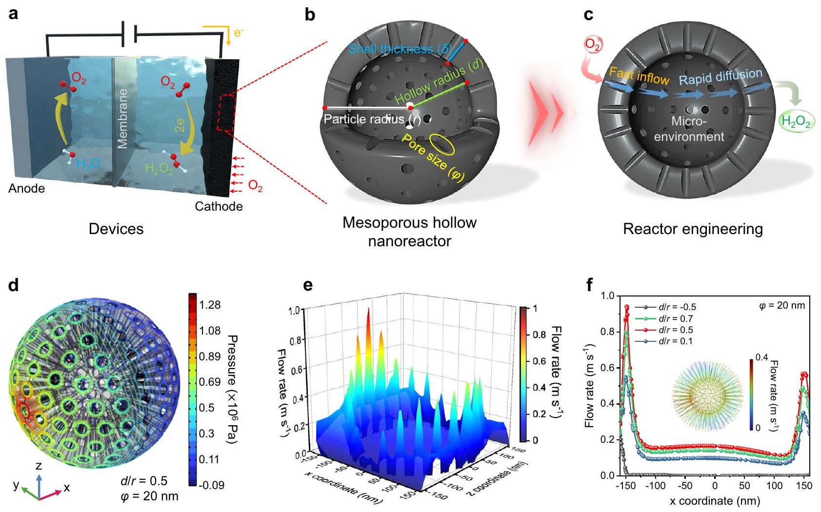
توزيع سرعة التدفق المكاني على المقطع العرضي. توزيع سرعة السائل عبر نماذج كرات الكربون المجوفة المسامية ) مع نسبة تجويف متغيرة ( ، و 0.7 ). إدراج في يظهر توزيع التدفق الخطي داخل نموذج الكرة المسامية المجوفة.
تتكون مثل هذه الشبكات النانوية المعدنية عادةً من طبقة قشرة مسامية داخلية وجوف داخلي، يمكن ضبطها بعدة معلمات هندسية حاسمة بما في ذلك نصف قطر الجسيمات ( حجم المسام ( سمك القشرة ( )، ونصف القطر المجوف( قد تؤثر هذه المعلمات الهيكلية على ديناميات السوائل داخل MHNs، مما ينظم الانتشار المحلي والبيئة الدقيقة، وبالتالي يؤثر على عملية التفاعل.
لتحقيق العلاقة بين بنية النانو رياكتور وسلوك السائل داخله، تم إجراء FES لضمان البناء المنهجي لشبكات الجزيئات النانوية والحفاظ على الموارد الحاسوبية للتحقيق في انتظام سائل الإلكتروليت، قمنا بتوحيد حجم الجسيمات إلى 300 نانومتر مع الحفاظ على مبدأ التباين الفريد لمختلف أو كما هو موضح في الشكل التكميلي 1a و 1b، نموذج كرة مجوفة مسامية ، تم بناؤه في فضاء مربع ثلاثي الأبعاد (3D) لتمثيل تدفق السوائل في نظام مضطرب، تم تعيين مدخل ومخرج حقل السائل كالجوانب اليسرى واليمنى، على التوالي (الشكل التكميلي 1c، d). يولد هذا الإعداد تدرج ضغط متناقص من اليسار إلى اليمين يدفع الماء للتدفق بشكل تلقائي عبر الهندسة المُنشأة (الشكل التكميلي 2). . من المثير للاهتمام، أن هناك انخفاضًا ملحوظًا في الضغط داخل المسام المتوسطة ( ) بالنسبة لسطح الكرة غير المسامية (الأشكال التكميلية 3 و 4). الفرق في الضغط عبر المسام المتوسطة يدفع تدفق الماء عبر القنوات إلى داخل الكرة، مما يزيد بشكل كبير من السطح التحفيزي المتاح من خلال زيادة الاتصال بين الإلكتروليت وسطح الكربون (الشكل 1d والشكل التكميلية 5). والأكثر إثارة للاهتمام، أنه مدفوعًا بهذا الفرق في الضغط، يظهر تسارع كبير في السوائل في القنوات المسامية المتوسطة ( )، مما يوحي بانتشار متزايد في MHNs (الأشكال التكميلية 6 و 7). رسم الخرائط ثلاثي الأبعاد لسرعة السائل في المقطع العرضي المركزي ( ) يؤكد على تعزيز الانتشار المحلي داخل القنوات المسامية المتوسطة ويشير إلى الإمكانية للتوصيل السريع لـ وإرهاق الناتج (الشكل 1e) .
لتقييم تأثير الانتشار وتحديد الحل الأمثل، مجموعة من معلمات حجم المسام ( ، و تمت محاكاة، جنبًا إلى جنب مع حساب توزيع سرعة السائل في مواقع محددة ( ) لتسهيل المقارنة والتحليل (الشكل التوضيحي التكميلي 6ب). تم ملاحظة أعلى معدلات التدفق في كل من قنوات المسام الدقيقة الداخلة والخارجة بحجم مسام يبلغ 20 نانومتر، على الرغم من معدل التدفق الأبطأ في الفراغ المجوف المرتبط بالمسام الدقيقة (الشكل التوضيحي التكميلي 8-10). بناءً على ما سبق، نستمر في الحفاظ على معلمات الجسيمات المماثلة ولكننا نغير نسب الفراغات المجوفة لتوقع نقل الكتلة السائلة. لذا، النماذج ذات نسب شغل الفراغات المجوفة المختلفة ( ، و 0.7) تم محاكاتها أيضًا (الأشكال التكميلية 9 و 11). تشير النتائج إلى أن حجمًا معينًا من الفراغ المجوف أمر حاسم، حيث يحدث الحد الأقصى لسرعة التدفق في القنوات المسامية المتوسطة عند (الشكل 1f). بالنظر إلى أن المواقع النشطة لتفاعل الاختزال الكهربائي للأكسجين (ORR) موزعة على السطح الكربوني للأصداف المسامية، فإن تعزيز الانتشار المحلي يمكّن من تدفق سريع لـ والنقل السريع لما تم توليده في المحلول الكثيف، مما يمنع تراكمه على سطح المحفز والتقليل الكهربائي اللاحق . تشير هذه النتائج إلى أن كثافة المسام المتوسطة قد تؤثر على سلوك السوائل داخل الشبكات النانوية المعدنية. بالنسبة لشبكة نانوية معدنية واحدة، فإن القليل من تشير النسبة إلى وجود قناة مسامية طويلة وكثافة مسامية عالية، مما يؤدي إلى مقاومة لزجة مستمرة تؤثر على معدل التدفق. . على العكس، فإن حجم كبير يشير إلى قناة مسامية قصيرة وهياكل مجوفة أكبر بكثافة مسامية أقل، مما يمكّن من دخول السوائل بسرعة إلى منطقة تخزين معدل التدفق المجوف، على الرغم من أنه يحد من تسارع السوائل. بالإضافة إلى ذلك، يُظهر نموذج MHN المعدل، الذي تم بناؤه بكثافة مسامية منخفضة، قدرة الإلكتروليت على الحفاظ على معدل تدفق مرتفع على مسافة طويلة (الشكل التكميلي 12). ومع ذلك، فإن انخفاض القنوات المسامية سيؤدي إلى تدفق معظم الإلكتروليت من سطح MHN بدلاً من المرور عبر المسام، مما قد يقلل من استخدام الفعالية الداخلية.
المواقع. قد تؤسس تأثيرات التخفيف السائل في المنطقة المجوفة بيئة ميكروية داخلية مستقرة محتملة. لتلخيص ذلك، تم استخدام محاكاة الديناميات الميكانيكية الدقيقة لتحديد المعلمات الهيكلية المواتية للاختلاط. ) وتوجيه تصميم الشبكات الصحية المتنقلة.

تنقيح وتوصيف الشبكات النانوية الكربونية

استنادًا إلى نتائج المحاكاة المذكورة أعلاه، تم تطوير نهج تجميع مشترك تسلسلي للعضويات واللاعضويات لتصنيع نانو رياكتورات قائمة على كرات الكربون المجوفة المسامية. كما هو موضح في الشكل التكميلي 13، يبدأ هذا النهج بتجميع وحدات زمنية للراتنج الفينولي العضوي والسيليكا غير العضوية. بالتفصيل، يتم بلمرة الريسورسينول والفورمالديهايد تحت تأثير محفز الأمونيا لتشكيل راتنجات الفينول، بينما يتم إضافة التترا بروبوكسي سيلاين (TPOS) في نفس الوقت ويخضع للهيدروlysis لتشكيل . ثم، تتجمع هذان العنصران بشكل تلقائي لتكوين الراتنج الهجين كرات (الشكل التوضيحي 14 أ، ب). بعد مزيد من التحلل الحراري لكرات الراتنج/السيليكا في جو خامل، يتم تحويل منطقة الراتنج إلى مكونات كربونية، مما يؤدي إلى تشكيل الكرات (الشكل التوضيحي التكميلي 14c، d). المادة الكربونية في تم القضاء على الكرات بشكل انتقائي عن طريق التحميص في جو هوائي، مما أدى إلى إنتاج كرات سيليكا مسامية. ) مع نواة صلبة، مما يوفر أدلة مقنعة على أن TPOS تم تحليله مائيًا في البداية لتشكيل النواة، التي تم إحاطتها لاحقًا بعملية هجين من الراتنج و (الشكل التكميلي 15). وبالتالي، فإن الإزالة الانتقائية لـ مكون من المادة السابقة الكروية أدت إلى تشكيل كرات كربونية مجوفة مسامية. عن طريق توليد المسام المتوسطة والفجوات في المناطق التي كانت مشغولة سابقًا بـ مرحلة علم الشكل تم تحليلها بواسطة SEM و TEM، مما كشف عن متوسط نصف قطر الجسيمات 210 نانومتر ونصف قطر مجوف 105 نانومتر، مما أدى إلى تسمية (الشكل 2أ-هـ). علاوة على ذلك، أظهرت المجهرية الإلكترونية الناقلة عالية الدقة (HRTEM) القنوات المسامية القابلة للاختراق على القشرة الخارجية (الشكل 2و). بالإضافة إلى ذلك، تم ملاحظة بعض القنوات المسامية التي تمر عبر طبقة القشرة بوضوح في كل من صور SEM للعينة المكسورة. وصور TEM المكبرة محليًا لـ ، مما يوفر مسارًا لتمرير سائل الإلكتروليت عبر الفراغ الداخلي المجوف (الشكل التكميلي 16). بالإضافة إلى ذلك، تؤكد صورة المجهر الإلكتروني الناقل بتقنية الحقل المظلم الزاوي العالي (HAADF-STEM) البنية المجوفة المسامية. ، بالإضافة إلى التوزيع المتساوي لعناصر الكربون والأكسجين (الشكل 2g، h). لتأكيد تدفق الإلكتروليت من خلال الفراغ الداخلي المجوف لـ قمنا بإجراء تقييم أولي لمدة ساعة باستخدام في محلول إلكتروليتي 0.5 م من كلوريد البوتاسيوم. بعد التفاعل، تم تجفيف العينات دون غسل للملاحظة المباشرة باستخدام المجهر الإلكتروني النافذ، مما يكشف عن وجود مكونات KCl المتبقية التي تملأ داخل (الشكل التوضيحي الإضافي 17). تم التحقق من هذه النتائج بشكل إضافي من خلال المسح الخطي العنصري المقابل، مما يؤكد وجود قنوات مسامية متوسطة تمر عبر طبقات القشرة لـ وتدفق سوائل الإلكتروليت من خلال هذه القنوات، مما يتيح حركة الإلكتروليت عبر الجزء الداخلي المجوف (الشكل التكميلي 18).
في استراتيجية التجميع المشترك الهجين العضوي غير العضوي المتسلسل، توقيت الراتنج و يمكن تعديل التجميع بشكل مرن لتعديل حجم الهيكل المجوف لـ MHCS بشكل كبير. حاولنا تعديل نقاط الزمن أثناء تشكيل الراتنج و لتحضير كرات مسامية متوسطة بحجوم فراغية متفاوتة. لتحقيق ذلك، أضفنا مونومرات الراتنج (ريسورسينول وفورمالديهايد) أولاً، تلاها إضافة TPOS بعد فترة زمنية محددة. ). من أجل تخليق قيمة تم التحكم فيه ليكون 0، مما يعني أن المونومرات الراتنج وTPOS المطلوبة للتحلل المائي لتشكيل تمت الإضافة في نفس الوقت. إذا تم إضافة TPOS قبل 20 دقيقة ( عملية التحلل المائي لـ TPOS
الشكل 2 | صور المجهر الإلكتروني للـ MHNs القائمة على الكربون التي تم تصنيعها. أ نموذج هيكلي، ب، ج صور SEM، د، هـ صور TEM، و صورة HRTEM، ز صورة HAADF-STEM، والصورة المقابلة صور رسم الخرائط العنصرية
نموذج هيكلي صورة SEM، و صور TEM لـ نموذج هيكلي صورة SEM، و صور TEM لـ نموذج هيكلي صورة SEM، و صور TEM لـ MCS
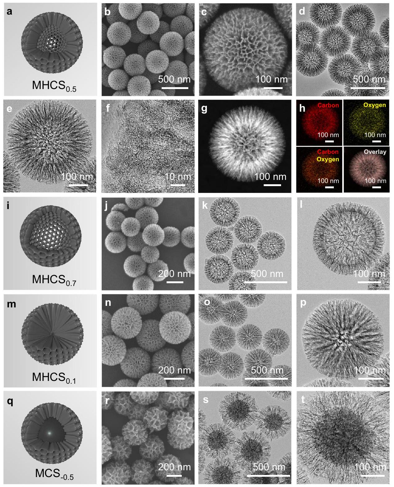
متقدم، مما يؤدي إلى تشكيل أكبر نواة صلبة قبل أن يتم دمجها مع الراتنج. بعد الكربنة و إزالة بحجم تجويف أكبر من تم تخليقه (الشكل 2i-l). من خلال تأخير إضافة السيلان بواسطة التجميع المشترك للهجين مع الراتنج يمكن أن تتقدم بشكل متناسب، مما يؤدي إلى تشكيل مع تجويف صغير جداً (الشكل. ) . علاوة على ذلك، من خلال إضافة مونومر الراتنج لمدة 80 دقيقة ثم تحليل TPOS ، يتم أولاً بلمرة نواة صلبة من الراتنج ثم يتم إحاطتها بتهجين من وراتنج، مما يؤدي إلى تشكيل كرات الكربون المسامية المتوسطة (المعروفة باسم MCS) ) مع نوى كربونية صلبة وأصداف كربونية مسامية ( الشكل 2q-t ). أظهرت المعلمات الهندسية لسلسلة MHCS المُصنَّعة ارتباطًا إيجابيًا واضحًا بين نسبة حجم الفراغ إلى حجم الجسيمات ( ) و الـ القيمة، مما يوفر دليلاً على التخليق المنضبط للنانوروافع المجوفة المسامية تحت manipulations زمنية (الجدول التكميلي 1 والشكل التكميلي 19).
تم إجراء بعض التجارب المقارنة أيضًا لتأكيد الدور لـ مشتق من التحلل المائي لـ TPOS، في تشكيل كرات الكربون المسامية المجوفة. بدون إضافة TPOS، سيحدث فقط بلمرة الراتنج الفينولي، مما يؤدي إلى تشكيل كرات راتنج غير مسامية (الشكل التكميلي 20). ثم ستنتج عملية التحلل الحراري لهذه الكرات الراتنجية كرات كربون ميكروية (CS، الشكل التكميلي 21). بالإضافة إلى ذلك، من خلال حرق مكونات الراتنج من راتنج/ كرات تم تجميعها في فترات زمنية مختلفة و 80) في الغلاف الجوي، كريات مسامية مختلفة الهياكل ذات الطوبولوجيات المعاكسة لتلك الخاصة بـ MHCS المقابل و تم الحصول على (الشكل التكميلي 22-24). تدعم هذه النتائج التلاعب المنضبط في التجميع الهرمي غير المتجانس لـ والراتنج بترتيب زمني محدد.
قمنا بتحليل الهيكل المسامي والخصائص الفيزيائية والكيميائية لخمس عينات: و
الشكل 3 | توصيف MHNs التي تم الحصول عليها. أ – منحنيات امتصاص وإزالة النيتروجين. منحنيات توزيع حجم المسام أنماط XRD، طيف رامان، طيف مسح XPS، و محتوى الأنواع عينات.
CS. كشفت إيزوثيرم امتصاص وإطلاق النيتروجين عن مساحات سطح محددة عالية (SSA) وفقًا لطريقة بروناوير-إيميت-تيلر (BET) تبلغ 830 و 1020 و 1169 و لـ ، و على التوالي (الشكل 3أ). كشفت طريقة بارّيت-جويتر-هاليندا عن توزيع حجم المسام المتوسطة لـ MHCS عينات لتكون في نطاق (الشكل 3ب). مقارنة بـ لديه مساحة سطح محددة أقل تبلغ فقط وقليل جداً من توزيع المسام المتوسطة (الشكل التوضيحي 25). أنماط حيود الأشعة السينية لـ وأظهرت CS قممًا عريضة عند و ، والتي تتوافق مع المستويات (002) و(100) من الهيكل الكربوني غير المنظم، على التوالي (الشكل 3c والشكل التكميلي 26a) أظهرت طيف رامان نسب كثافة مشابهة لشرائط D و G وعرض خط G لـ لجميع العينات الخمس، مما يدل على الخصائص النموذجية للكربون غير المتبلور مع عيوب قابلة للمقارنة (الشكل 3d والشكل التكميلية 26b) أظهر تحليل XPS محتوى أكسجين يبلغ حوالي لـ (الشكل 3e). الـ الطيف يظهر ثلاثة قمم عند 284.6 و 286.0 و 288.7 إلكترون فولت، والتي تت correspond إلى ، و ، على التوالي، بينما الطيف يظهر ذروتين مخصصتين لـ و (الشكل التوضيحي 27 والشكل التوضيحي 28) الشكل 3f والجدول التكميلي 2 يظهران أن توزيع المجموعات الوظيفية المحتوية على الأكسجين، التي تعتبر مواقع نشطة للتفاعل الكهروكيميائي 2e يشبه بين المختلفين عينات. بالإضافة إلى ذلك، كان لدى CS تركيبة كيميائية مشابهة لـ (الشكل التوضيحي 29). بالإضافة إلى ذلك، تم اقتراح الكربون المعيب أو بعض حواف الكربون كمواقع نشطة محتملة لتفاعل اختزال الأكسجين (2 e ORR) في بعض الدراسات السابقة. لفحص الكربون المعيب، استخدمنا الرنين المغناطيسي الإلكتروني (EPR) ولاحظنا شدة إشارات متطابقة تقريبًا على ، مما يشير إلى أن تظهر مستوى ثابت من العيوب في عملية الاختزال الكهربائي للأكسجين 2e (الشكل التكميلي 30). هذه الخصائص المماثلة التي لوحظت في يمكن أن يُعزى ذلك إلى أصلها المشترك ككربون مشتق من راتنج ريسورسينول-فورمالديهايد ومرورها بنفس عملية الكربنة. لذلك، فإن هذه الكرات الكربونية التي تم الحصول عليها لها خصائص كيميائية ومواقع نشطة مشابهة، مع اختلافات تتركز بشكل رئيسي في حجم الفراغ وسمكها.
الأصداف المسامية المتوسطة، مما يجعلها نماذج مثالية لاستكشاف فعالية MHNs في التفاعلات الحفزية.

أداء التحفيز الكهربائي

كإثبات للمفهوم، تم استخدام تفاعل الاختزال الكهربائي 2e ORR كاختبار لتقييم تكثيف العملية الحفازة بسبب نقل السوائل في هذه السلسلة من MHNs القائمة على كرات الكربون. تم تقييم الأداء الكهربائي باستخدام تقنية القطب الدوار ثلاثي الأقطاب (RRDE) بسرعة 1600 دورة في الدقيقة في محلول إلكتروليتي مشبع، مع تعيين قطب حلقة البلاتين عند 1.2 فولت مقابل القطب الهيدروجيني القابل للعكس (RHE) للكشف عن الناتج على القرص. من المRemarkably، الـ يحقق كثافة تيار قرص محدد الانتشار كبيرة عند 0.20 فولت مقابل RHE ، تقترب من الحد النظري لـ ORR (الشكل 4أ) . بالإضافة إلى ذلك، الـ يوفر إمكانات بدء عالية تبلغ 0.85 فولت مقابل RHE، أكبر من التوازن الديناميكي الحراري إمكانات ORR قد ينبع ارتفاع جهد بدء تفاعل الأكسدة الاختزالية من هيكله المسامي المناسب وإطار العمل الهندسي، مما يعزز الاتصال مع سوائل الإلكتروليت لتحسين استخدام مواقع السطح النشطة للكربون في بيئة الإلكتروليت. . وبالمثل، وُجد أن النشاط الكهروكيميائي لـ CS غير المسامي كان ضعيفًا، كما يتضح من كثافات التيار المنخفضة جدًا عند ظروف تحديد الانتشار، مما يشير إلى عدم كفاية تعرض المواقع النشطة في المسام الدقيقة (الشكل التكميلي 31). يوضح الشكل 4b و c الحسابات التي تم إجراؤها الانتقائية وعدد نقل الإلكترونات المقابل ) لـ عينات. ال المحفز يقدم العالي الانتقائية ) و قيمة حوالي 2.05 عبر نافذة محتملة واسعة ( ، من 0.3 فولت إلى 0.8 فولت مقابل RHE)، والتي تتفوق على تلك الخاصة بمعظم المحفزات المبلغ عنها سابقًا (الجدول التكميلي 3). انخفاضات في تمت ملاحظة الانتقائية بالترتيب ، و ، مما يظهر علاقة إيجابية مع معدل التدفق المحاكى في قنوات المسام المتوسطة لنماذج MHNs المقابلة.
لفهم الفروق في الخصائص الكهروكيميائية لـ من الضروري الكشف عن المواقع النشطة الجوهرية المعنية
الشكل 4 | الأداء الكهروكيميائي لـ MHNs. أ منحنيات LSV لقياسات RRDE عند 1600 دورة في الدقيقة في المقابل الانتقائية، وعدد نقل الإلكترونات c عند مختلف الجهود المطبقة. د مخططات تافل المستمدة من منحنيات LSV في 0.1 M KOH. هـ النشاط الكهروكيميائي المُعدل و التيار الجزئي قيد التشغيل (عند 0.6 فولت مقابل RHE)، جنبًا إلى جنب مع الانتقائية وسرعة تدفق الإلكتروليت. رسم تخطيطي يوضح تدفق السائل/
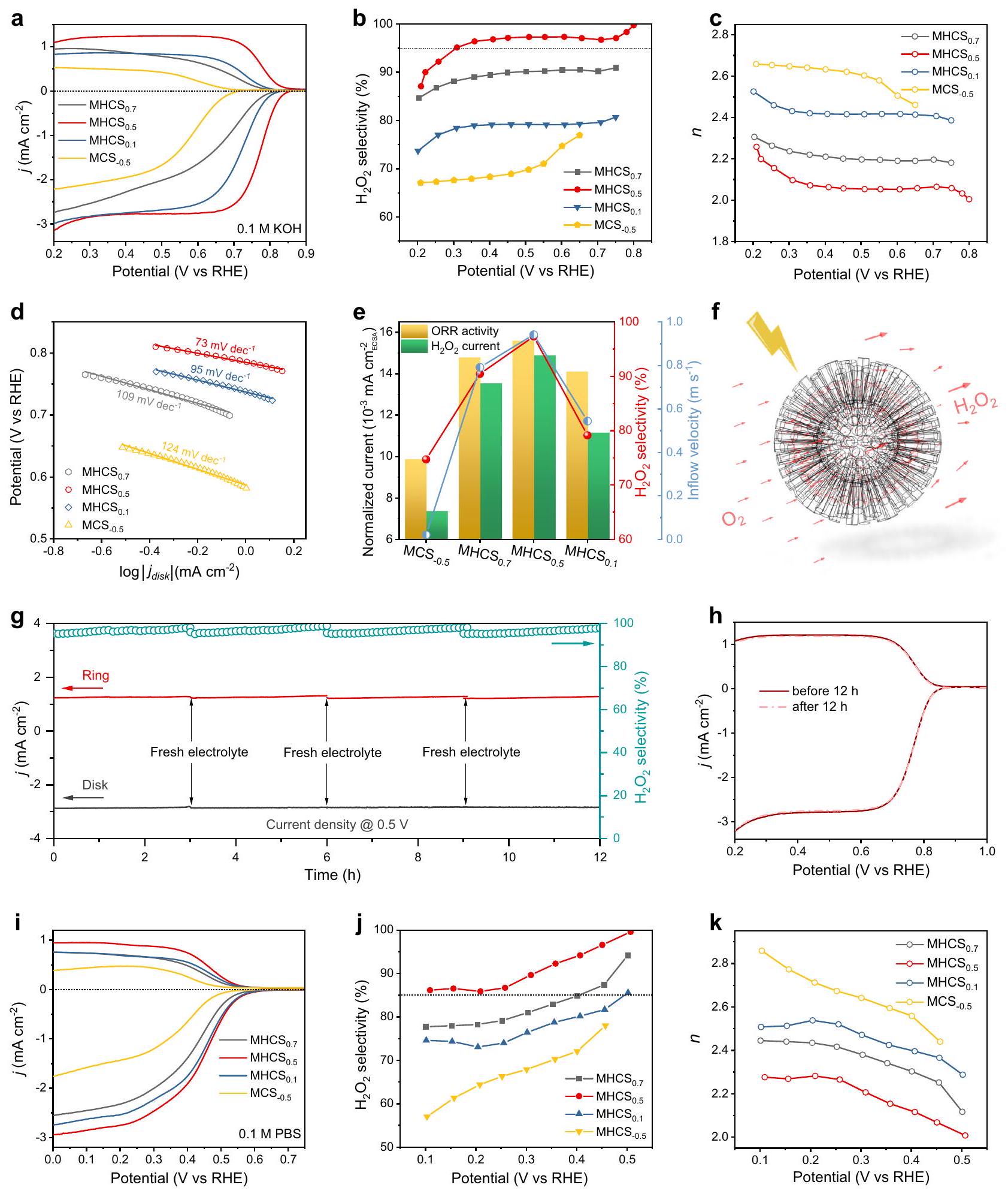
الأكسجين وعملية اختزال الأكسجين على نموذج. قياسات الاستقرار لـ عند جهد قرص ثابت قدره 0.5 فولت مقابل RHE في 0.1 م KOH. منحنيات LSV لـ MHCS قبل وبعد اختبار الاستقرار لمدة 12 ساعة. منحنيات LSV لقياسات RRDE عند 1600 دورة في الدقيقة في محلول PBS بتركيز 0.1 م. المقابل الانتقائية، و عدد نقل الإلكترون عند مختلف الجهود المطبقة.
في عملية الاختزال الكهروكيميائي لتفاعل الأكسدة الاختزالية للأكسجين. لقد قمنا بتقليل عينة مختلطة جو لإزالة مكون الأكسجين، مما يؤدي إلى R-MHCS بمحتوى أكسجين منخفض يصل إلى (الشكل التوضيحي 32a). وبالتالي، فإن نشاط ORR و انتقائية
R-MHCS تم تقليلها بشكل كبير (الشكل التوضيحي 32b)، مما يشير إلى أن الأنواع الأكسجينية على مصفوفة الكربون تعمل كمصدر نشط لـ ORR، بما يتماشى مع بعض التقارير السابقة . بالنظر إلى الأنواع المقارنة من الأكسجين على الاختلاف الملحوظ في
يُنسب الانتقائية إلى سلوك السوائل للإلكتروليتات ضمن هياكل مختلفة من MHNs. الشكل 4d يعرض انحدارات تافل لـ MHCS. ، مع MHCS يظهر قيمة منخفضة تبلغ 73 مللي فولت لكل عقد “، مما يدل على حركيات تفاعل سريعة. تعكس مخططات تافل خطوات تحديد المعدل المختلفة (RDS)، وقد يشير الانخفاض التدريجي في انحدارات تافل إلى تحول في RDS من خطوة نقل الإلكترون الأولى ( ، ) إلى الأخير خطوة إزالة الامتصاص ، . تم دراسة مسار ORR من منظور تفاعل اختزال ) النشاط في -مشبع 0.1 م كOH يحتوي على بين تظهر خمولًا واضحًا تجاه مع تيارات ضئيلة، مما يؤكد مسار 2e الانتقائي للغاية (الشكل التكميلي 33). على النقيض من ذلك، لاحظنا اتجاهًا متزايدًا في التيار من ، إلى MCS-0.5، مما يشير إلى تحسين القدرة. بالنظر إلى سرعة السائل المحاكية على نستنتج أن معدلات التدفق المنخفضة ستعزز المسار غير المباشر 4e لتقليل الـ الانتقائية .
تم تقييم هذه المحفزات الكهربية القائمة على كرات الكربون بشكل إضافي من حيث مساحة السطح النشطة المتاحة (ECSA) باستخدام سعة الطبقة المزدوجة ( ) الطريقة. على وجه التحديد، قيم لـ ، ، و تم حسابها لتكون 8.04 و 7.20 و 4.36 و 3.17، على التوالي (الشكل التكميلي 34، 35). من المثير للاهتمام أن قيم MHCS لا تتماشى مع إجمالي مساحة سطح BET الخاصة بهم، بل تظهر بدلاً من ذلك ارتباطًا إيجابيًا مع مساحة السطح الخارجية باستثناء المنطقة الميكرو مسامية (الشكل التكميلية 35b) بالنظر إلى شكل الجسيمات يمكن افتراض أن تعرض السطح الداخلي، الذي تسهله القنوات المسامية، يعزز التفاعل بين الإلكتروليت والمواقع النشطة، مما يعزز النشاط الكهروكيميائي المتزايد. بشكل بارز، الارتفاع قيمة على يشير إلى انتشارها الهيكلي المواتي، مما يوحي بتوفير سريع لأيونات الإلكتروليت واستخدام فعال للمواقع النشطة. بالإضافة إلى ذلك، فإن CS غير المسامي يظهر انخفاضاً في من ، مما يوضح بشكل أكبر الوصول المحدود للميكرو مسام بواسطة الإلكتروليتات (الشكل التوضيحي التكميلي 36 . علاوة على ذلك، استخدمنا ECSA لتوحيد النشاط الكهروكيميائي و تيارات جزئية من عند إمكانيات مرتبطة بالانتشار (0.6 فولت مقابل RHE)، كما هو موضح في الشكل 4e. من المثير للاهتمام أن التيارات المنضبطة المرتبطة وانتقائية 2e تظهر ارتباطًا إيجابيًا مع سرعة تدفق الإلكتروليت المحاكية، مما يوفر دليلًا إضافيًا على العلاقة بين تأثير الانتشار والأداء الكهروكيميائي على هذه MHNs. هذه الخصائص توضح تأثير معلمات الهيكل الفارغ على الانتشار وانعكاسها على الأداء الكهروتحفيزي (الشكل 4f).
لتقييم الاستقرار الحفزي، أجرينا اختبارات كرونوأمبريومترية لـ باستخدام تقنية RRDE عند جهد قرص ثابت قدره 0.5 فولت مقابل RHE. خلال الاختبار المستمر، تم تجميع قد يؤدي ذلك إلى زيادة طفيفة في التيار الحلقي ومن ثم في الانتقائية. للحفاظ على تيار حلقي ثابت، قمنا بتغيير الإلكتروليت كل 3 ساعات وأجرينا تنظيفًا كيميائيًا كهربائيًا لحلقة البلاتين لإزالة أي آثار للتراكم. خلال التشغيل المستمر. أظهرت النتائج أن نظام MHCS حافظ المحفز على تيارات قرص/حلقة مستقرة وحقق أكثر من 95% من الانتقائية طوال اختبار مستمر لمدة 12 ساعة (الشكل 4 ج). علاوة على ذلك، أجرينا اختبار متانة معجل (ADT) على عن طريق مسح الجهد بين 0.2 و 1.0 فولت مقابل RHE لمدة 12 ساعة. تؤكد منحنيات الفولتمترية الخطية المماثلة التي تم الحصول عليها قبل وبعد اختبار التحمل طويل الأمد على استقراره العالي (الشكل 4h). بعد التحليل الكهربائي على المدى الطويل، لا يزال يحتفظ بهيكله المسامي المجوف، وتظل تركيبته الكيميائية متسقة مع حالته قبل التفاعل، مما يضمن استقراره وقابليته لإعادة الاستخدام (الأشكال التكميلية 37 و38). ومن المثير للاهتمام بشكل خاص، يظهر أداءً استثنائيًا في تفاعل اختزال الأكسجين (ORR) في ظروف الكتروليت محايدة (pH 7)، مع تيار قرص محدود بالانتشار قدره عند 0.2 فولت مقابل RHE، جهد بدء قدره 0.6 فولت مقابل RHE، و انتقائية تتجاوز ، يتجاوز الشاسع
الغالبية العظمى من المحفزات المعتمدة على الكربون المبلغ عنها في الأدبيات (الشكل 4i-k والجدول التكميلي 4). الاتجاهات الملحوظة في نشاط ORR وانتقائيته لـ تحت الظروف المحايدة كانت متوافقة مع تلك التي لوحظت تحت الظروف القلوية. ومن المثير للاهتمام أن منحنيات الاستقطاب تظهر مجموعتين متميزتين من الانحدارات عند إمكانيات مختلفة، مما يشير إلى تباينات في آلية اختزال الأكسجين. بشكل متسق، اختبار تم إجراؤه على كشف عن انخفاض كثافة التيار، مما يدل على عدم نشاطه العام تجاه في إلكتروليت محايد، مع زيادة طفيفة لوحظت عند إمكانيات أكثر سلبية (الشكل التكميلي 39). هذه الاتجاه في الـ يتماشى التيار الحالي مع ذلك الخاص بـ ORR، مما يبرز تأثير عملية 4e غير المباشرة عند الفولتية العالية نسبيًا على انتقائية 2e. .

فعلي خصائص التخليق الكهربائي

التطبيق العملي لـ تم تقييم المحفزات باستخدام إعداد خلية من النوع H في 0.1 م KOH مع استمرارية تكون الفقاعات (الشكل التوضيحي 40أ). المنتج تم قياسه بواسطة طريقة المعايرة باستخدام تقنية الطيف الضوئي فوق البنفسجي-المرئي (UV-vis). خلال اختبار الاستقرار على المدى الطويل عند جهد ثابت قدره 0.5 فولت مقابل RHE، يبقى التيار مستقرًا عند حوالي وتركيز المتراكم يزداد باستمرار، مما يؤدي إلى خلال 12 ساعة (الشكل التوضيحي 40ب). خلال الاختبار المستمر على المدى الطويل، كانت تقلبات التيار وكفاءة فاراداي (FE) (> 97%) ضئيلة، مما يشير إلى العملية الموثوقة للكتلة. محفز كهربائي
لمعالجة قيود توليد البيروكسيد في تكوين خلية H ثابتة، التي تتميز بنقل الكتلة غير الفعال بسبب انخفاض كفاءة الانتشار و معدل الإزالة، مما يؤدي إلى إنتاجية ظاهرة دون المستوى الأمثل، قمنا بتقييم الفعلي بشكل أكبر إنتاج من باستخدام إعداد خلية تدفق (الشكل 5 أ والشكل التكميلي 41). في القياسات، تم استخدام إلكترود ورق الكربون المحمّل (CP)، بما في ذلك طبقة انتشار الغاز (GDL)، ككاثود، و عمل كأنود في خلية التدفق. كما هو موضح في الشكل 5ب، أظهر زيادة حادة في كثافة التيار مع ارتفاع الجهد، ليصل إلى في 0.1 م كوه في محلول فوسفات مخفف بتركيز 0.1 م عند جهد غير معوض قدره 0.1 فولت مقابل RHE. علاوة على ذلك، فإن التيار لـ أظهر ملفًا ثابتًا ومستقرًا خلال التحليل الكهربائي المستمر عند جهد مطبق قدره 0.1 فولت مقابل RHE (الشكل التكميلية 42). ومن الجدير بالذكر أن عائد الإنتاج لـ أظهر زيادة مستمرة مع مرور الوقت، مع عائد تراكمي لمدة 16 ساعة من وصلت إلى 68.7 مليمول في 0.1 م كوه و 50.6 مليمول في 0.1 م PBS، مما يتوافق مع معدلات الإنتاج 17.18 و (الشكل 5ج، د) وتتفوق على معظم المحفزات الكهربائية المبلغ عنها مؤخرًا (الجدول التكميلي 5). بالإضافة إلى ذلك، فإن كفاءة فاراداي لـ التحليل الكهربائي على ظل ثابتًا حول خلال اختبار طويل الأمد. بعد 16 ساعة من التخليق الكهربائي في خلية التدفق، كانت التركيز التراكمي لـ وصلت في بيئة قلوية و في وسط محايد، يلبي متطلبات التركيز لمطهرات الدرجة الطبية من الجدير بالذكر، الإنتاج الكهربائي لـ تعتبر الحلول في الإلكتروليتات المحايدة جذابة بشكل خاص بسبب صداقة البيئة، وقلة التآكل، وإمكانية تقليل تكاليف خلايا التحليل الكهربائي. . بالإضافة إلى ذلك، محايد توفر الحلول خيارًا مستدامًا ومتعدد الاستخدامات للتطبيقات العملية، بما في ذلك الاستخدام المباشر للمواد المصنعة في الأنظمة البيوكيميائية الأداء القوي والانتقائية الممتازة لتقليل 2e التي تم إثباتها بواسطة في إعداد خلية التدفق، تحقق من إمكانياتها للتطبيقات العملية في الكيمياء الكهربائية الإنتاج، وخاصة للإنتاج الكهربائي للحيادي حلول . على النقيض، أظهرت نشاطًا كيميائيًا كهربائيًا محدودًا، مع تيارات تبلغ 51 مللي أمبير عند 0.1 م KOH و25 مللي أمبير عند 0.1 م PBS عند جهد مطبق قدره 0.1 فولت مقابل RHE (الشكل التكميلي 43a). بالإضافة إلى ذلك، فإن FE لـ لـ الإنتاج الكهربائي حوالي ، أقل بكثير من ذلك لـ القطب الكهربائي (الشكل التوضيحي التكميلي 43ب، ج). هذا الملحوظ
الشكل 5 | الفعلي الإنتاج الكهربائي القائم على MHNs. مخطط تخطيطي لخلايا التدفق لـ التحليل الكهربائي منحنيات الاستقطاب لـ قطب كهربائي محمّل في خلية تدفق. ج الزمن المعتمد على التحليل الكهربائي إنتاج وكفاءة فارادايك تحت المستمر التطهير في 0.1 م كوه. التحليل الكهربائي
اعتمادًا على الوقت إنتاج وكفاءة فارادايك تحت الاستمرار التطهير في 0.1 م PBS. تم تصور إنتاج كهرباء خضراء مدفوعة بالكهرباء على نطاق واسع من خلال العمليات الكهروكيميائية مطهر
تؤكد التمييز في الأداء الكهروكيميائي بشكل أكبر على فعالية الهياكل النانوية القائمة على كرات الكربون المصممة.
استنادًا إلى النشاط الملحوظ، العالي الانتقائية، والاستقرار الموثوق به لـ ، جنبًا إلى جنب مع الهدف العالمي لتحقيق الحياد الكربوني، نتخيل مستقبلًا حيث الإنتاج على نطاق واسع من يتم تحقيق المطهرات باستخدام مصادر الطاقة المستدامة كما هو موضح في الشكل 5e، يتم استخدام الكهرباء الخضراء الزائدة الناتجة عن مصادر الطاقة الشمسية والمائية والرياح كمصدر للطاقة للأنظمة اللامركزية. الإنتاج في مجموعة خلايا كهربائية. بشكل ملحوظ، الدرجة الطبية يمكن تخزين المحلول المنتج تحت ظروف محايدة بشكل أنيق أو استخدامه مباشرة لأغراض التعقيم والتطهير. هذه الكهرباء الخضراء المدفوعة يمثل إنتاج المطهرات نهجًا مستدامًا يتيح الإنتاج والاستخدام في الموقع لـ لتجاوز التلوث، واستهلاك الطاقة العالي، ومخاطر الانفجار المرتبطة بصناعة جودة الهواء التقليدية. في سعي لتحقيق هذا الهدف، ستعمل كرات الكربون المهندسة في النانو رياكتور كعوامل حفازة محورية لتحقيق هذه الرؤية.

تأثير تعديل الميكروبيئة للنانوركترات

للحصول على فهم أعمق لأداء 2e ORR الاستثنائي لـ ، وخاصة في الظروف المحايدة، قمنا بإجراء محاكاة واسعة لتوضيح الآلية التحفيزية للنانوراكتر المجوف المسامي. لتوفير تمثيل بصري للداخل داخل النانوراكتر، تم إنشاء نموذج ثنائي الأبعاد (2D) لكرية مجوفة مسامية ( تم بناؤه كما هو موضح في الشكل التكميلي 44، يتم نمذجة الكرة المجوفة المسامية على أنها تحتوي على جميع الأسطح كمواقع نشطة تحفيزياً وتوضع داخل مجال محاكاة مربع. )، مع تحديد حدود تدفق المدخلات والمخرجات للإلكتروليت عند الجانبين الأيسر والأيمن. بما يتماشى مع نتائج المحاكاة ثلاثية الأبعاد السابقة، السائل الإلكتروني المحتوي على الإلكتروليت يتم دفعه بواسطة تدرج الضغط للتدفق عبر المسام المجوفة للمجال الكروي ويخرج في النهاية من نطاق المحاكاة (الشكل التكميلي 45). حصلنا على توزيع السرعة عند ورصدت
تسارع كبير في تدفق السائل في منطقة المسام المتوسطة، بينما كانت سرعة التدفق داخل المنطقة المجوفة منخفضة نسبيًا (الشكل التوضيحي 46). يمكن أن تزيد معدلات التدفق العالية من انخراط لكل وحدة زمنية، كما يتضح من توزيع التركيز المكاني لـ كونه تقريبًا متناسبًا مع توزيع معدل التدفق، مما يؤدي إلى إثراء في قنوات المسام (الشكل 6 أ، ب). من منظور حركية التفاعل، فإن التركيز المحلي لـ في القنوات المسامية المتوسطة يمكن أن تعزز تفعيل وتحفز تشكيل بالإضافة إلى استهلاك البروتونات لتوليد تراكم الذي يتم توليده، والذي يعمل كعازل للتدفق، يسبب ارتفاعًا محليًا في درجة الحموضة داخل MHNs، كما تؤكد نتائج محاكاة العناصر المحدودة (الشكل 6c، d). بعد التحليل الكهربائي في وسط محايد ( )، تم إسقاط مؤشر الفينولفثالين بسرعة على القطب الكهربائي وتم إدخاله في زجاجة تحتوي على إلكتروليت محايد. لوحظ ظهور لون أحمر بنفسجي طفيف على السطح الكهربائي، مما يوفر دليلاً على وجود بيئة ميكروية زائفة قلوية موضعية (الشكل التكميلية 47). بشكل أكثر مباشرة، لوحظ تغيير كبير في اللون في الموقع على سطح القطب أثناء تفاعل اختزال الأكسجين (ORR) ثنائي الإلكترون في إلكتروليت محايد ) يحتوي على الفينولفثالين (الشكل التوضيحي التكميلي 48). حدث هذا التغير في اللون وعملية التحفيز الكهربائي تقريبًا في نفس الوقت، مما يوفر دليلًا على زيادة محلية في درجة الحموضة بالقرب من طبقة المحفز (فيلم تكميلي 1). بعد ذلك، أجرينا التجارب التالية للتحقق من قدرة MHNs على تراكم OH. في البداية، كما هو موضح في الشكل 6e، تم تنفيذ عملية ORR لمدة 10 دقائق في إلكتروليت محايد باستخدام محفز كروي من الكربون عند 0.4 فولت مقابل RHE، مع تسجيل كثافة التيار المقابلة في الشكل التوضيحي التكميلي 49a. بعد ذلك، تم استخراج جميع الأقطاب من الخلية، وتم شطف القطب العامل عن طريق الغمر في 5 مل من محلول مائي. تم تكرار هذه العملية 10 مرات، وتم قياس درجة حموضة المحلول المائي. يوضح الشكل 6f أن أسطح الأقطاب الكهربائية أظهرت مستويات أعلى التركيزات مقارنةً بالعناصر الأخرى. هذه الملاحظة مرتبطة بكثافة التيار العالية الناتجة عن الأقطاب الكهربائية، مما يؤدي إلى زيادة
الشكل 6 | تعديل البيئة الدقيقة في MHNs. أ التوزيع المكاني لـ تركيز في نموذج كرة الكربون المسامية ، )، و المقابل منحنى توزيع التركيز لنموذج كرات الكربون المسامية التوزيع المكاني لـ تركيز نموذج كرة الكربون المسامية ، )، و المقابل منحنى توزيع التركيز لـ
نموذج كرة الكربون المسامية المتوسطة على مخطط تخطيطي لعملية اختبار تركيز على سطح القطب. مقارنة بين تركيزات على السطح من طيف رامان في الموقع لـ القطب عند جهد الدائرة المفتوحة والجهد المطبق (0.1 فولت مقابل RHE) في 0.1 م محلول فوسفات البوتاسيوم.
مقارنة لطيف رامان في الموقع على القطب عند الجهد المطبق (0.1 فولت مقابل RHE).
إنتاج المنتجات الثانوية. بالإضافة إلى ذلك، لوحظ أنه لا توجد علاقة خطية بين كثافات التيار والقياسات التي تم أخذها. تركيزات لكل قطب كهربائي من كرات الكربون (الشكل التكميلي 49ب، ج). بل، أظهر القطب الكهربائي الذي يحتوي على كرة كربون ذات هيكل مجوف ارتفاعًا ملحوظًا في التركيز. لذلك، ننسب التركيز المحلي تراكم على القطب الكهربائي إلى التأثيرات المجمعة لنشاطه الكهروكيميائي العالي وتكوينه الهندسي المجوف المفضل. توفر هذه النتائج دليلًا تجريبيًا يدعم نتائج المحاكاة التي تم مناقشتها أعلاه.
لتحقيق تأثير التحسين وارتفاع الرقم الهيدروجيني المحلي في تفاعل اختزال الأكسجين ثنائي الإلكترون داخل كرات الكربون القائمة على MHNs، استخدمنا مطيافية رامان في الموقع لاستكشاف تفاعلات المحفز مع الممتزات. ). في جو من الأكسجين، طيف رامان لـ تم عرض القطب عند جهد الدائرة المفتوحة (OCV) وإمكان مطبق قدره 0.1 فولت مقابل RHE في الشكل 6g. تم ملاءمة حزمة D بواسطة الأوضاع المميزة لـ D1 و D2 و D3 و D4 عند ~1130 و 1200 و 1340 و على التوالي . بالمقارنة مع OCV، اتسع ذروة D وظهرت ذروة D1، مما يعكس الامتزاز لـ ، و
تشير قمة D4 الأكثر حدة المقابلة إلى تكوين أكبر لمتوسط *OOH . يمكن استنتاج هذه الظاهرة على النحو التالي: إثراء وزيادة مستوى الحموضة المحلي في MHNs تسارع معدل التفاعل، مما يسهل تفعيل تثبيت المتوسطات، ومنع عملية بروتنة *OOH المتوسطات المرتبطة بـ مسار، مما يعزز جيل كما هو موضح في الشكل 6h، أظهرت مقارنة طيف رامان في الموقع لجميع العينات أوضح اهتزازات تمدد O-O. و إشارات على ، مما يشير إلى تسارع معدل التفاعل داخل التكوين السائد الذي يتميز ببيئات تفاعل ملائمة.
نقدم ملخصًا عن الخصائص الوظيفية لنانوريكتور كرات الكربون المجوفة المسامية في عملية الاختزال الكهربائي للأكسجين 2e. تسهل القنوات المسامية تسريع السوائل لنقل الناتج. في المحلول الكثيف، مما يقلل من احتمال حدوث اختزال كهربائي إضافي له على سطح المحفز . بالإضافة إلى ذلك، فإن تدفق الإلكتروليت المتسارع يضخ الركائز بسرعة لتغنيتها . بالإضافة إلى ذلك، فإن معدل التفاعل المتسارع والملائم
تُعزز التكوينات المجوفة ارتفاع درجة الحموضة المحلية، مما يوفر بيئة ميكروية مناسبة لتفاعل اختزال الأكسجين ثنائي الإلكترون (2e ORR). تؤكد نتائج التجارب، وقياسات رامان في الموقع، هذه الوظائف للنانوهياكل المجوفة المستندة إلى كرات الكربون المهندسة، والتي يمكن مقارنتها ببعض الوظائف الهيكلية للخلايا: حيث إن الغلاف المسامي للنانوهياكل المجوفة يشبه غشاء الخلية ويسيطر بشكل فعال على دخول وخروج الركائز والمنتجات؛ بينما يوفر الجزء الداخلي المجوف للنانوهياكل، الذي يشبه السيتوبلازم داخل الخلايا، بيئة داخلية ملائمة للتفاعل. على الرغم من أن مثالنا قد يفتقر إلى الوحدات الوظيفية المعقدة والمتطورة الموجودة في البيولوجيا، إلا أنه لا يزال مصدر إلهام لبناء النانو رياكتورات من خلال تقليد الطبيعة.

نقاش

باختصار، استكشفت هذه الدراسة الوظائف التحفيزية للهياكل النانوية القائمة على الكربون. بالتفصيل، قمنا بتصميم داخل الكرات الكربونية المسامية، مستلهمين من FES لتدفق السوائل، مما أدى إلى بناء سلسلة من النانو-مفاعلات النموذجية. من خلال استخدام تفاعل الاختبار 2e ORR، نقدم أدلة على تحسين الانتشار، وتكثيف المتفاعلات، وتعديل البيئة الدقيقة التي تسهلها الهياكل المجوفة المسامية. ترتبط هذه الوظائف التحفيزية ارتباطًا وثيقًا بالمعايير الهيكلية للهياكل النانوية، مما يبرز أهمية التحكم في الميكروهيكل للنانو-مفاعل من أجل التفاعلات المستهدفة. مع الوظائف التحفيزية للنانو-مفاعل، تم تحسين تظهر المحفزات نشاطًا واختيارًا مثيرين للإعجاب في التحليل الكهربائي تحت ظروف قلوية ومحايدة. علاوة على ذلك، فإن إنتاج درجة طبية يؤكد المطهر في جهاز خلية التدفق الإمكانات العملية الكبيرة لهندسة هذا النانو رياكتور. بشكل عام، تُظهر هذه الدراسة التنفيذ الناجح لهندسة النانو رياكتور في فحص المحفزات ذات التوجه الوظيفي، مما يمهد الطريق لمجموعة واسعة من تطبيقات النانو رياكتور.

طرق

تركيب كرات الكربون المسامية النانوية ذات الهياكل الداخلية المختلفة
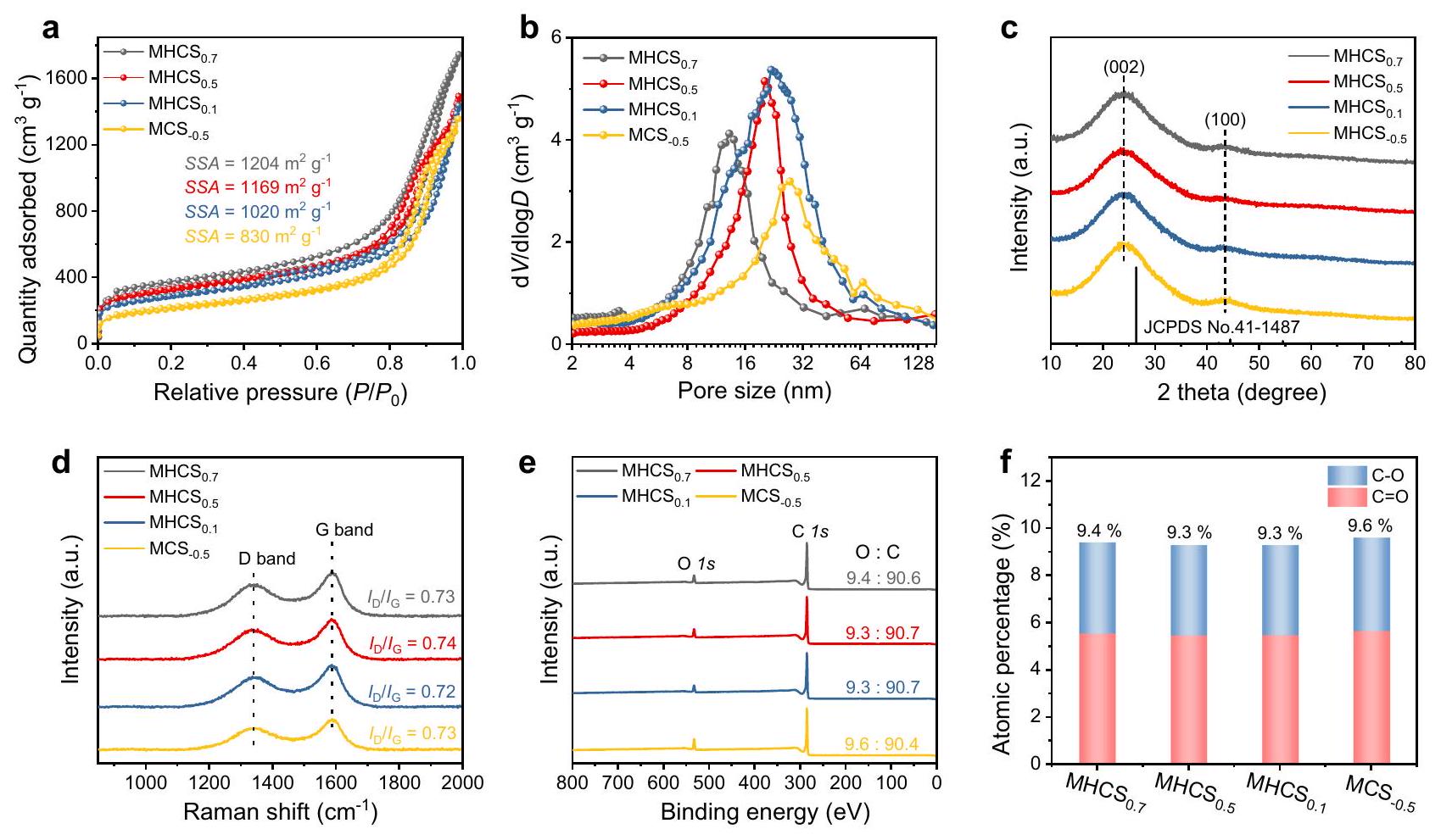
في تخليق نموذجي، يتم تحضير محلول مكون من 65 مل من الإيثانول و15 مل من تم خلطه مع 2.5 مل من و 0.8 مل من الفورمالديهايد في درجة حرارة الغرفة. بعد ذلك، تم إضافة 0.6 جرام من الريسورسينول و 6 مل من TPOS إلى المحلول المختلط تحت التحريك. تم تحريك التفاعل لمدة 24 ساعة في درجة حرارة الغرفة، وتم الحصول على المنتجات عن طريق الطرد المركزي، تلاها غسل بالماء والإيثانول، وتجفيف في فرن. تم إخضاع المنتجات الناتجة لعملية التحلل الحراري عند درجة حرارة لمدة ساعتين في معدل تسخين قدره ، تليها إزالة القالب السيليكا من خلال النقش بـ تحدد البنية الداخلية للكرات الكربونية بواسطة الترتيب الزمني لإضافة الريسورسينول وTPOS. ، و تمت تخليقها عن طريق إضافة الريسورسينول وTPOS على فترات من ، و80 دقيقة، على التوالي. تم إعداد CS دون إضافة TPOS. تقليل تم إجراء ذلك في فرن أنبوبي في لمدة ساعتين تحت مزيج الجو، مما يؤدي إلى المنتج المشار إليه بـ .

خصائص المواد

تم الحصول على صور المجهر الإلكتروني الماسح (SEM) باستخدام مجهر ماسح (SU8230، اليابان). تم إجراء المجهر الإلكتروني الناقل (TEM) باستخدام Tecnai G2 F30 (أمريكا) وJEM2100 (اليابان). تم الحصول على بيانات حيود الأشعة السينية البودرة باستخدام جهاز حيود Rigaku D/Max2500PC مع إشعاع Å عبر نطاق من بسرعة مسح تبلغ عند درجة حرارة الغرفة. تم إجراء قياسات رامان باستخدام مطياف (NanoWizard Ultra Speed & inVia Raman) مع ليزر له طول موجي تحفيزي يبلغ 532 نانومتر. امتصاص النيتروجين
تم تسجيل خطوط العزل عند 77 كلفن (Tristar 3020، الولايات المتحدة الأمريكية). تم جمع بيانات طيف الإلكترون الضوئي (XPS) باستخدام مصدر أحادي اللون من الألمنيوم (KRATOS، Axis Ultra). تم إجراء قياسات الرنين المغناطيسي الإلكتروني (EPR) باستخدام مطياف EPR من نوع Bruker ECSEMX في درجة حرارة الغرفة.

القياسات الكهروكيميائية

تم إجراء جميع القياسات الكهروكيميائية باستخدام محطة عمل كهروكيميائية (PARSTAT 3000A-DX) مع خلية ثلاثية الأقطاب في درجة حرارة الغرفة. تم استخدام قطب مرجعي من Ag/AgCl مزود بجسر ملحي للقضاء على إمكانيات الحدود السائلة ومنع التلوث المتبادل بين محلول نظام الدراسة ونظام القطب المرجعي. بالإضافة إلى ذلك، تم استخدام شريحة من البلاتين كقطب مضاد، وعمل قطب دوار ذو حلقة قرص محمّل بالمواد الحفازة (RRDE) كقطب عمل. تضمنت مجموعة RRDE قطب دوار من الكربون الزجاجي (مساحة القرص: “) وخاتم من البلاتين (مساحة الخاتم: ) مع كفاءة جمع ( ) من 0.37.
في تحضير حبر المحفز، تم توزيع 5.0 ملغ من المحفز الكهربائي في من الإيثانول و من محلول نافيون. بعد المعالجة بالموجات فوق الصوتية لـ تم إسقاط حبر المحفز على القطب الكهربائي القرصي.
تمت القياسات الكهروكيميائية في درجة حرارة الغرفة في محلول مائي مشبع 0.1 م من هيدروكسيد البوتاسيوم (pH 13) و . تم تدوير القطب العامل بسرعة ثابتة تبلغ 1600 دورة في الدقيقة خلال الاختبارات. تم تحويل جميع الجهود للإشارة إلى القطب الهيدروجيني القابل للعكس (RHE) باستخدام المعادلة التالية:
تم إجراء قياس الفولطية بالمسح الخطي المستقر (LSV) بمعدل مسح في الإلكتروليتات المشبعة بـ و لضمان الأكسدة الكاملة لـ تم الحفاظ على جهد القطب الحلقي عند 1.2 فولت مقابل RHE. انتقائية وعدد نقل الإلكترون ( تم حسابها بناءً على تيار القرص ) والتيار الدائري ( ) كالتالي المعادلات:

قياس المساحة السطحية النشطة كيميائيًا

تم تحديد المساحة السطحية النشطة كهربائياً (ECSA) باستخدام طريقة السعة الثنائية الطبقة. تم إجراء مسح الفولتمترية الدورانية عند جهد ثابت في منطقة الطبقة الثنائية، تتراوح من -0.06 إلى 0.04 فولت مقابل ، بمعدلات مسح تبلغ 20 و40 و60 و80 و رسم سرعة المسح كالمتغير السيني و( ) كالمتغير العمودي، تم حساب قيمة الميل لتمثيل سعة الطبقة المزدوجة ( )، والذي يرتبط خطيًا بـ ECSA. تم تحديد ECSA من خلال حساب باستخدام المعادلات التالية:
حيث السعة النوعية ( ) لسطح القطب، وعادة ما يقع ضمن النطاق من 20 إلى . على وجه التحديد، اعتمدنا قيمة تشير إلى مساحة سطح القطب.

التحليل الكهربائي بالجملة

التحضير الكهربائي بالجملة لـ تم إجراء ذلك في 0.1 م KOH باستخدام جهاز تحليل كهربائي من نوع H-cell مخصص لمزيد من التحقيق في الجوانب العملية
أداء التحليل الكهربائي. كانت الإلكترود العامل المستخدم هو إلكترود ورق الكربون مغطاة بـ أما بالنسبة للقطب المرجعي وقطب العداد، فإن القطب المصنوع من البلاتين و تم استخدام أقطاب (KCl المشبع) على التوالي. كانت الغرف مفصولة بغشاء نافيوني. كان المحلول الكهربائي يتكون من محلول مائي من هيدروكسيد البوتاسيوم 0.1 م مشبع.

الكشف المباشر عن التغيرات المحلية في درجة الحموضة على القطب

للمراقبة غير المباشرة للتغيرات في الرقم الهيدروجيني المحلي، تم استخدام المحفز لتسهيل عملية اختزال الأكسجين ثنائية الإلكترون لمدة 10 دقائق في الخلية الكهروكيميائية (0.1 م PBS، ثم تم إيقاف تشغيل الجهد المطبق، وتم نقل القطب العامل إلى 5 مل من المحلول المائي وشطفه. بعد تكرار هذين الخطوتين 10 مرات، تم قياس قيمة الرقم الهيدروجيني في زجاجة الكواشف باستخدام مقياس الرقم الهيدروجيني. لضمان دقة التجربة، تم إجراء هذه التجربة الموازية 5 مرات.
لرصد مباشر لارتفاع درجة الحموضة على سطح الإلكترود، قمنا بمراقبة تغير اللون على سطح القطب الكهربائي خلال تفاعل الأكسدة والاختزال عند 0.1 فولت مقابل RHE. تم إجراء التفاعل في خلية إلكتروليتية من نوع H باستخدام يحتوي على 1 ملغ من الفينولفثالين كإلكتروليت للتصور.

العائد في خلية التدفق

التركيب الكهروكيميائي لـ تم إجراء ORR عبر إعداد خلية تدفق ذات حجرة مزدوجة مفصولة بغشاء نافيوني. تم إنشاء تجميع الكاثود في طبقة انتشار الغاز من خلال تطبيق حبر المحفز على ورق الكربون، مع مساحة عمل فعلية قدرها وحمولة المحفز من . تم استخدامه كإلكترود مرجعي، و عمل كأنود. في اختبار خلية التدفق، إلكتروليت PBS تم تداولها عبر كل حجرة بمعدل تدفق قدره بينما كانت الكاثود تتلقى إمدادًا مستمرًا من بمعدل .

قياس التركيز

مقدار تم تحديده باستخدام طريقة المعايرة التقليدية لسلفات السيريوم، وفقًا للمعادلة:
في هذه الطريقة، الأصفر يتم تقليله بواسطة إلى عديم اللون . أ تم إعداد المحلول عادة عن طريق إذابة في 100 مل من محلول حمضي. تم إنشاء منحنى المعايرة من خلال التناسب الخطي لقيم الامتصاص عند طول موجي 320 نانومتر لتركيزات معروفة تبلغ 0.01، 0.02، ، و باستخدام منحنى المعايرة هذا، فإن تركيز المركب المخفض في الحل النموذجي تم تحديده عن طريق قياس شدة امتصاص الأشعة فوق البنفسجية والمرئية (الشكل التكميلي 50). أخيرًا، الـ تم حساب العائد بناءً على التركيز المعروف للمخفض الكفاءة الفارادية (FE) لـ يتم حساب الجيل بالمعادلة التالية:

محاكاة العناصر المحدودة

تم إجراء محاكاة باستخدام برنامج COMSOL Multiphysics للتحقيق في العلاقة بين تدفق الإلكتروليت ونقل الكتلة في نموذج النانو رياكتور المجوف المسامي (MHN)، مع الأخذ في الاعتبار التأثيرات الحملية والانتشارية. ، و OH. تم استخدام كل من النماذج ثلاثية الأبعاد وثنائية الأبعاد لمحاكاة معدل التدفق وتوزيع المواد في MHNs، على التوالي.
لنمذجة MHCS المُركب تم بناء MHNs بشكل موحد مع نصف قطر جزيئي يبلغ 150 نانومتر وقناة مسامية تبلغ حوالي 20 نانومتر، مع اعتبار نسبة المكون المجوف كمتغير وحيد. توضح هذه الطريقة بشكل فعال تأثيرات مختلفة نسب نقل السوائل عند حجم جزيئات موحد، مع تحسين الكفاءة الحاسوبية دون المساس بالدقة. بالإضافة إلى ذلك، تم محاكاة ومقارنة نماذج بأحجام مسام مختلفة. لتبسيط الأمر، تم تجاهل التشوه، واعتُبر أن النموذج في وضع ثابت. تم إنشاء فراغين بحجم 10 نانومتر على الجانبين الأيسر والأيمن من القناة المسامية لمحاكاة تدفق المواد الداخلة والخارجة في الهيكل غير المسامي. استخدم نموذج المحاكاة هندسة محورية لحساب سرعة السوائل والضغط في المناطق المسامية والفارغة، بالإضافة إلى توزيع تركيز المواد المتفاعلة. في هذا النموذج، تم تحديد الجانبين الأيسر والأيمن كمدخل ومخرج للإلكتروليت، على التوالي، مع نقل الكتلة المدفوع بتدفق السوائل وانتشار التركيز. المعادلات الحاكمة هي كما يلي:
حيث المتغيرات التابعة هي السرعة ( )، الضغط ( ) والتركيز ( ). هي كثافة السائل، هي لزوجة السائل، هو معامل الانتشار للمادة i ، و هو معدل التفاعل. بالنسبة لنموذج MHNs ثلاثي الأبعاد/ثنائي الأبعاد، يحدث دخول الإلكتروليت من اليسار، ويعبر منطقة النموذج، ويخرج من اليمين. لمحاكاة التدفق الناتج عن دوران المحلول، تم تعيين سرعة المدخل إلى ، مع شرط حدود ضغط صفري عند المخرج. نظرًا لنظام عدد رينولدز المنخفض ( ) الناتج عن الحجم الصغير لـ تم اختيار وحدة “التدفق الطبقي” لمحاكاة مجال التدفق. عند حدود مدخل النموذج، تم تشبع الحل بـ تم تحديده، بتركيز قدره عند حدود التدفق العلوي. تم تكوين حدود التدفق الخارجي مع تعيين تدفق الانتشار إلى 0. تم تحديد سطح النموذج كمكان حدوث التفاعل، و يتم استهلاكه للتحويل. خلال المحاكاة، قمنا بدراسة تأثيرات الأبعاد الهندسية، مثل قطر المسام المتوسطة والمسافة بينها، على و تركيزات. تم اشتقاق المعلمات الهندسية المطلوبة للمحاكاة من البيانات التجريبية، بما في ذلك صور المجهر الإلكتروني.

توفر البيانات

البيانات الرئيسية التي تدعم نتائج هذه الدراسة متاحة ضمن النص الرئيسي وملف المعلومات التكميلية. تم إيداع البيانات الرئيسية التي تم توليدها في هذه الدراسة في قاعدة بيانات figshare تحت رمز الوصولhttps://doi.org/10.6084/m9.figshare. 24935178.

References

  1. Vriezema, D. M. et al. Self-assembled nanoreactors. Chem. Rev. 105, 1445-1490 (2005).
  2. Yu, Z. et al. Kinetics driven by hollow nanoreactors: an opportunity for controllable catalysis. Angew. Chem. Int. Ed. 62, e202213612 (2023).
  3. Petrosko, S. H., Johnson, R., White, H. & Mirkin, C. A. Nanoreactors: small spaces, big implications in chemistry. J. Am. Chem. Soc. 138, 7443-7445 (2016).
  4. Marguet, M., Bonduelle, C. & Lecommandoux, S. Multicompartmentalized polymeric systems: towards biomimetic cellular structure and function. Chem. Soc. Rev. 42, 512-529 (2013).
  5. Weiss, M. et al. Sequential bottom-up assembly of mechanically stabilized synthetic cells by microfluidics. Nat. Mater. 17, 89-96 (2018).
  6. Wang, G.-H. et al. Platinum-cobalt bimetallic nanoparticles in hollow carbon nanospheres for hydrogenolysis of 5-hydroxymethylfurfural. Nat. Mater. 13, 293-300 (2014).
  7. Zhu, W. et al. Functionalization of hollow nanomaterials for catalytic applications: nanoreactor construction. Adv. Mater. 31, 1800426 (2019).
  8. Ding, S. et al. Formation of hollow nanospheres inside mesoporous silica nanoreactors. J. Am. Chem. Soc. 133, 21-23 (2011).
  9. Tian, H. et al. Construction of hollow mesoporous silica nanoreactors for enhanced photo-oxidations over Au-Pt catalysts. Nat. Sci. Rev. 7, 1647-1655 (2020).
  10. Yu, Z. et al. Ruthenium-nanoparticle-loaded hollow carbon spheres as nanoreactors for hydrogenation of levulinic acid: explicitly recognizing the void-confinement effect. Angew. Chem. Int. Ed. 60, 20786-20794 (2021).
  11. Dong, C. et al. Hollow carbon sphere nanoreactors loaded with PdCu nanoparticles: void-confinement effects in liquid-phase hydrogenations. Angew. Chem. Int. Ed. 59, 18374-18379 (2020).
  12. Yu, Q. et al. Space-confined carbon-doped Pd nanoparticles as a highly efficient catalyst for selective phenol hydrogenation. ACS Catal. 13, 3925-3933 (2023).
  13. Tian, Q. et al. Exceptional photocatalytic hydrogen peroxide production from sandwich-structured graphene interlayered phenolic resins nanosheets with mesoporous channels. Adv. Funct. Mater. 33, 2213173 (2023).
  14. Tang, . et al. Carbon nanocage with maximum utilization of atomically dispersed iron as efficient oxygen electroreduction nanoreactor. Adv. Mater. 35, 2208942 (2023).
  15. Hung, C.-T. et al. Gradient hierarchically porous structure for rapid capillary-assisted catalysis. J. Am. Chem. Soc. 144, 6091-6099 (2022).
  16. Yu, Z. et al. Metal-loaded hollow carbon nanostructures as nanoreactors: microenvironment effects and prospects for biomass hydrogenation applications. ACS Sustain. Chem. Engin. 9, 2990-3010 (2021).
  17. Xie, G., Zhang, J. & Ma, X. Compartmentalization of multiple catalysts into outer and inner shells of hollow mesoporous nanospheres for heterogeneous multi-catalyzed/multi-component asymmetric organocascade. ACS Catal. 9, 9081-9086 (2019).
  18. Li, X. et al. Amorphous NiFe oxide-based nanoreactors for efficient electrocatalytic water oxidation. Angew. Chem. Int. Ed. 62, e202300478 (2023).
  19. Wang, X. et al. Balancing mass transfer and active sites to improve electrocatalytic oxygen reduction by B, N Codoped C nanoreactors. Nano Lett. 23, 4699-4707 (2023).
  20. Boyjoo, Y. et al. Engineering nanoreactors for metal-chalcogen batteries. Energy Environ. Sci. 14, 540-575 (2021).
  21. Swisher, J. H., Jibril, L., Petrosko, S. H. & Mirkin, C. A. Nanoreactors for particle synthesis. Nat. Rev. Mater. 7, 428-448 (2022).
  22. Tian, H., Liang, J. & Liu, J. Nanoengineering carbon spheres as nanoreactors for sustainable energy applications. Adv. Mater. 31, 1903886 (2019).
  23. Liu, J., Wickramaratne, N. P., Qiao, S. Z. & Jaroniec, M. Molecularbased design and emerging applications of nanoporous carbon spheres. Nat. Mater. 14, 763-774 (2015).
  24. Wang, T., Okejiri, F., Qiao, Z. A. & Dai, S. Tailoring polymer colloids derived porous carbon spheres based on specific chemical reactions. Adv. Mater. 32, 2002475 (2020).
  25. Chen, S. et al. Chemical identification of catalytically active sites on oxygen-doped carbon nanosheet to decipher the high activity for electro-synthesis hydrogen peroxide. Angew. Chem. Int. Ed. 133, 16743-16750 (2021).
  26. Lim, J. S. et al. Designing highly active nanoporous carbon production electrocatalysts through active site identification. Chemistry 7, 3114-3130 (2021).
  27. Wang, Z. et al. Hydrogen peroxide generation with faradaic efficiency on metal-free carbon black. ACS Catal. 11, 2454-2459 (2021).
  28. Wang, W., Zheng, Y., Hu, Y., Liu, Y. & Chen, S. Intrinsic carbon defects for the electrosynthesis of . J. Phys. Chem. Lett. 13, 8914-8920 (2022).
  29. San Roman, D. et al. Engineering three-dimensional (3D) out-ofplane graphene edge sites for highly selective two-electron oxygen reduction electrocatalysis. ACS Catal. 10, 1993-2008 (2020).
  30. Sa, Y. J., Kim, J. H. & Joo, S. H. Active edge-site-rich carbon nanocatalysts with enhanced electron transfer for efficient electrochemical hydrogen peroxide production. Angew. Chem. Int. Ed. 58, 1100-1105 (2019).
  31. Ding, Y. & Qiao, Z. A. Carbon surface chemistry: new insight into the old story. Adv. Mater. 34, 2206025 (2022).
  32. Li, Z., Li, B., Yu, C., Wang, H. & Li, Q. Recent progress of hollow carbon nanocages: general design fundamentals and diversified electrochemical applications. Adv. Sci. 10, 2206605 (2023).
  33. Xia, C., Xia, Y., Zhu, P., Fan, L. & Wang, H. T. Direct electrosynthesis of pure aqueous solutions up to by weight using a solid electrolyte. Science 366, 226-231 (2019).
  34. Jiang, Y. et al. Selective electrochemical production through two-electron oxygen electrochemistry. Adv. Energy Mater. 8, 1801909 (2018).
  35. Zhou, Y., Chen, G. & Zhang, J. A review of advanced metal-free carbon catalysts for oxygen reduction reactions towards the selective generation of hydrogen peroxide. J. Mater. Chem. A 8, 20849-20869 (2020).
  36. Sun, Y., Han, L. & Strasser, P. A comparative perspective of electrochemical and photochemical approaches for catalytic production. Chem. Soc. Rev. 49, 6605-6631 (2020).
  37. Tian, Z. et al. Constructing interfacial boron-nitrogen moieties in turbostratic carbon for electrochemical hydrogen peroxide production. Angew. Chem. Int. Ed. 134, e202206915 (2022).
  38. Hu, C., Paul, R., Dai, Q. & Dai, L. Carbon-based metal-free electrocatalysts: from oxygen reduction to multifunctional electrocatalysis. Chem. Soc. Rev. 50, 11785-11843 (2021).
  39. Bu, Y. et al. Carbon-based electrocatalysts for efficient hydrogen peroxide production. Adv. Mater. 33, 2103266 (2021).
  40. Jiang, K., Zhao, J. & Wang, H. Catalyst design for electrochemical oxygen reduction toward hydrogen peroxide. Adv. Funct. Mater. 30, 2003321 (2020).
  41. Li, L. et al. Tailoring selectivity of electrochemical hydrogen peroxide generation by tunable pyrrolic-nitrogen-carbon. Adv. Energy Mater. 10, 2000789 (2020).
  42. Perry, S. C. et al. Electrochemical synthesis of hydrogen peroxide from water and oxygen. Nat. Rev. Chem. 3, 442-458 (2019).
  43. Jing, L. et al. Mesoscale diffusion enhancement of carbon-bowl-shaped nanoreactor toward high-performance electrochemical production. ACS Appl. Mater. Inter. 13, 39763-39771 (2021).
  44. Deng, Z., Gong, M., Gong, Z. & Wang, X. Mesoscale mass transport enhancement on well-defined porous carbon platform for electrochemical synthesis. Nano Lett. 22, 9551-9558 (2022).
  45. Park, J., Nabae, Y., Hayakawa, T. & Kakimoto, M. A. Highly selective two-electron oxygen reduction catalyzed by mesoporous nitrogendoped carbon. ACS Catal. 4, 3749-3754 (2014).
  46. Grunberg, L. & Nissan, A. H. Mixture law for viscosity. Nature 164, 799-800 (1949).
  47. Zhang, H. et al. Surfactant-free assembly of mesoporous carbon hollow spheres with large tunable pore sizes. ACS Nano 10, 4579-4586 (2016).
  48. Mei, S. C. et al. Sequential assembly tailored interior of porous carbon spheres for boosted water decontamination through peroxymonosulfate activation. Adv. Funct. Mater. 32, 2111184 (2022).
  49. Xie, L. et al. Kinetics-controlled super-assembly of asymmetric porous and hollow carbon nanoparticles as light-sensitive smart nanovehicles. J. Am. Chem. Soc. 144, 1634-1646 (2022).
  50. Tian, Q. et al. Micelle-templating interfacial self-assembly of twodimensional mesoporous nanosheets for sustainable electrosynthesis. Sustain. Mater. Technol. 32, e00398 (2022).
  51. Schwan, J., Ulrich, S., Batori, V., Ehrhardt, H. & Silva, S. Raman spectroscopy on amorphous carbon films. J. Appl. Phys. 80, 440-447 (1996).
  52. Kim, H. W. et al. Efficient hydrogen peroxide generation using reduced graphene oxide-based oxygen reduction electrocatalysts. Nat. Catal. 1, 282-290 (2018).
  53. Wu, K.-H. et al. Highly selective hydrogen peroxide electrosynthesis on carbon: in situ interface engineering with surfactants. Chemistry 6, 1443-1458 (2020).
  54. Chen, S. et al. Defective carbon-based materials for the electrochemical synthesis of hydrogen peroxide. ACS Sustain. Chem. Engin. 6, 311-317 (2018).
  55. Tang, C. et al. Coordination tunes selectivity: two-electron oxygen reduction on high-loading molybdenum single-atom catalysts. Angew. Chem. Int. Ed. 132, 9256-9261 (2020).
  56. Han, G.-F. et al. Building and identifying highly active oxygenated groups in carbon materials for oxygen reduction to . Nat. Commun. 11, 2209 (2020).
  57. Chang, Q. et al. Promoting production via 2-electron oxygen reduction by coordinating partially oxidized Pd with defect carbon. Nat. Commun. 11, 2178 (2020).
  58. Peng, L. et al. Versatile nanoemulsion assembly approach to synthesize functional mesoporous carbon nanospheres with tunable pore sizes and architectures. J. Am. Chem. Soc. 141, 7073-7080 (2019).
  59. Lu, Z. Y. et al. High-efficiency oxygen reduction to hydrogen peroxide catalysed by oxidized carbon materials. Nat. Catal. 1, 156-162 (2018).
  60. Zhao, K. M. et al. Insight into the mechanism of axial ligands regulating the catalytic activity of Fe-N4 sites for oxygen reduction reaction. Adv. Energy Mater. 12, 2103588 (2022).
  61. Tang, C. et al. Tailoring acidic oxygen reduction selectivity on single-atom catalysts via modification of first and second coordination spheres. J. Am. Chem. Soc. 143, 7819-7827 (2021).
  62. Bonakdarpour, A., Dahn, T. R., Atanasoski, R., Debe, M. K. & Dahn, J. release during oxygen reduction reaction on Pt nanoparticles. Electrochem. Solid-State Lett. 11, B2O8 (2008).
  63. Yao, W. et al. Hierarchically ordered macro-mesoporous electrocatalyst with hydrophilic surface for efficient oxygen reduction reaction. Adv. Mater. 35, 2301894 (2023).
  64. Ding, J. et al. Tunable periodically ordered mesoporosity in palladium membranes enables exceptional enhancement of intrinsic electrocatalytic activity for formic acid oxidation. Angew. Chem. Int. Ed. 132, 5130-5139 (2020).
  65. Wu, Z.-Y. et al. A general synthesis of single atom catalysts with controllable atomic and mesoporous structures. Nature Synth. 1, 658-667 (2022).
  66. Jung, E., Shin, H., Hooch Antink, W., Sung, Y.-E. & Hyeon, T. Recent advances in electrochemical oxygen reduction to : catalyst and cell design. ACS Energy Lett. 5, 1881-1892 (2020).
  67. Wen, Y. et al. Electrochemical reactors for continuous decentralized production. Angew. Chem. Int. Ed. 134, e202205972 (2022).
  68. Li, Y. et al. Single-atom iron catalyst with biomimetic active center to accelerate proton spillover for medical-level electrosynthesis of disinfectant. Angew. Chem. Int. Ed. 62, e202306491 (2023).
  69. Wei, X. et al. Synergistically enhanced single-atomic site Fe by for boosted oxygen reduction in neutral electrolyte. Nano Energy 84, 105840 (2021).
  70. Jiang, K. et al. Highly selective oxygen reduction to hydrogen peroxide on transition metal single atom coordination. Nat. Commun. 10, 3997 (2019).
  71. Zhang, L., Han, L., Liu, H., Liu, X. & Luo, J. Potential-cycling synthesis of single platinum atoms for efficient hydrogen evolution in neutral media. Angew. Chem. Int. Ed. 129, 13882-13886 (2017).
  72. Chu, S. & Majumdar, A. Opportunities and challenges for a sustainable energy future. Nature 488, 294-303 (2012).
  73. Gong, F. et al. Modulation of Mo-Fe-C sites over mesoscale dif-fusion-enhanced hollow sub-micro reactors toward boosted electrochemical water oxidation. Adv. Funct. Mater. 32, 2202141 (2022).
  74. Yang, C. et al. Interfacial accumulation affects microenvironment in carbon-based electrocatalysts for production. ACS Energy Lett. 7, 4398-4407 (2022).
  75. Melchionna, M., Fornasiero, P. & Prato, M. The rise of hydrogen peroxide as the main product by metal-free catalysis in oxygen reductions. Adv. Mater. 31, 1802920 (2019).
  76. Dong, K. et al. Honeycomb carbon nanofibers: a superhydrophilic -entrapping electrocatalyst enables ultrahigh mass activity for the two-electron oxygen reduction reaction. Angew. Chem. Int. Ed. 60, 10583-10587 (2021).
  77. Wei, J. et al. Probing the oxygen reduction reaction intermediates and dynamic active site structures of molecular and pyrolyzed Fe-N-C electrocatalysts by in situ Raman spectroscopy. ACS Catal. 12, 7811-7820 (2022).
  78. Tse, E. C. et al. Proton transfer dynamics control the mechanism of reduction by a non-precious metal electrocatalyst. Nat. Mater. 15, 754-759 (2016).

شكر وتقدير

تم دعم هذا العمل ماليًا من قبل المؤسسة الوطنية للعلوم الطبيعية في الصين (رقم 52172217، لج.ي.)، مؤسسة العلوم ما بعد الدكتوراه في الصين (رقم 2023M742391، ل.ج.)، مؤسسة العلوم الطبيعية في مقاطعة قوانغدونغ (رقم 2021A1515010144، لج.ي.)، برنامج العلوم والتكنولوجيا في شنتشن (رقم JCYJ202101324120400002 و ZDSYS20220527171401003، لج.ي.).

مساهمات المؤلفين

كيانغ تيان: المنهجية، التحقيق، تنظيم البيانات، التصور، كتابة المسودة الأصلية، كتابة المراجعة والتحرير. لينغيان جينغ: الحصول على التمويل، التحقيق، تنظيم البيانات، الاقتراحات والتعليقات، كتابة المراجعة والتحرير. هونغنان دو، يونتشاو يين، شياولاي تشينغ، جياكسين شيو، وجونيو تشين: استكشاف جزئي. زهوكسين ليو: الاقتراحات والتعليقات، كتابة المراجعة والتحرير. جياسو وان: كتابة المراجعة والتحرير. جيان ليو: الاقتراحات والتعليقات، كتابة المراجعة والتحرير. جينلونغ يانغ: الحصول على التمويل، الإشراف، الاقتراحات والتعليقات، كتابة المراجعة والتحرير.

المصالح المتنافسة

يعلن المؤلفون عدم وجود مصالح متنافسة.

معلومات إضافية

معلومات إضافية النسخة الإلكترونية تحتوي على
المواد التكميلية متاحة على
https://doi.org/10.1038/s41467-024-45243-w.
يجب توجيه المراسلات والطلبات للحصول على المواد إلى لينغيان جينغ أو جينلونغ يانغ.
معلومات مراجعة الأقران تشكر مجلة Nature Communications تشوانغانغ هو، يونغ جين سا، والمراجعين المجهولين الآخرين على مساهمتهم في مراجعة هذا العمل. يتوفر ملف مراجعة الأقران.
معلومات إعادة الطباعة والتصاريح متاحة على
http://www.nature.com/reprints
ملاحظة الناشر: تظل شركة سبرينغر ناتشر محايدة فيما يتعلق بالمطالبات القضائية في الخرائط المنشورة والانتماءات المؤسسية.
الوصول المفتوح هذه المقالة مرخصة بموجب رخصة المشاع الإبداعي النسب 4.0 الدولية، التي تسمح بالاستخدام والمشاركة والتكيف والتوزيع وإعادة الإنتاج بأي وسيلة أو صيغة، طالما أنك تعطي الائتمان المناسب للمؤلفين الأصليين والمصدر، وتوفر رابطًا لرخصة المشاع الإبداعي، وتوضح ما إذا تم إجراء تغييرات. الصور أو المواد الأخرى من طرف ثالث في هذه المقالة مشمولة في رخصة المشاع الإبداعي الخاصة بالمقالة، ما لم يُشار إلى خلاف ذلك في سطر الائتمان للمواد. إذا لم تكن المادة مشمولة في رخصة المشاع الإبداعي الخاصة بالمقالة وكان استخدامك المقصود غير مسموح به بموجب اللوائح القانونية أو يتجاوز الاستخدام المسموح به، فستحتاج إلى الحصول على إذن مباشرة من صاحب حقوق الطبع والنشر. لعرض نسخة من هذه الرخصة، قم بزيارةhttp://creativecommons.org/رخصة/بواسطة/4.0/.
© المؤلف(ون) 2024

  1. مختبر شنتشن الرئيسي لمواد التحفيز الكهربائي للطاقة، مركز غوانغدونغ للبحث في الهندسة السطحية للمواد الوظيفية، كلية علوم وهندسة المواد، جامعة شنتشن، شنتشن، الصين. كلية الفيزياء والهندسة البصرية والإلكترونية، جامعة شنتشن، شنتشن، الصين. كلية الكيمياء والهندسة البيئية، جامعة شنتشن، شنتشن، الصين. المختبر الوطني الرئيسي للتفاعل الكيميائي، معهد داليان للفيزياء الكيميائية، الأكاديمية الصينية للعلوم، داليان، الصين. المعهد العالمي لتكنولوجيا المستقبل، جامعة جياوتونغ بشنغهاي، شنغهاي، الصين. البريد الإلكتروني: lingyan.jing@foxmail.com; yangjl18@szu.edu.cn

Journal: Nature Communications, Volume: 15, Issue: 1
DOI: https://doi.org/10.1038/s41467-024-45243-w
PMID: https://pubmed.ncbi.nlm.nih.gov/38302469
Publication Date: 2024-02-01

Mesoporous carbon spheres with programmable interiors as efficient nanoreactors for electrosynthesis

Received: 23 August 2023
Accepted: 16 January 2024
Published online: 01 February 2024
(A) Check for updates

Qiang Tian © , Lingyan Jing (1) , Hongnan Du , Yunchao Yin , Xiaolei Cheng , Jiaxin Xu , Junyu Chen , Zhuoxin Liu , Jiayu Wan , Jian Liu & Jinlong Yang

Abstract

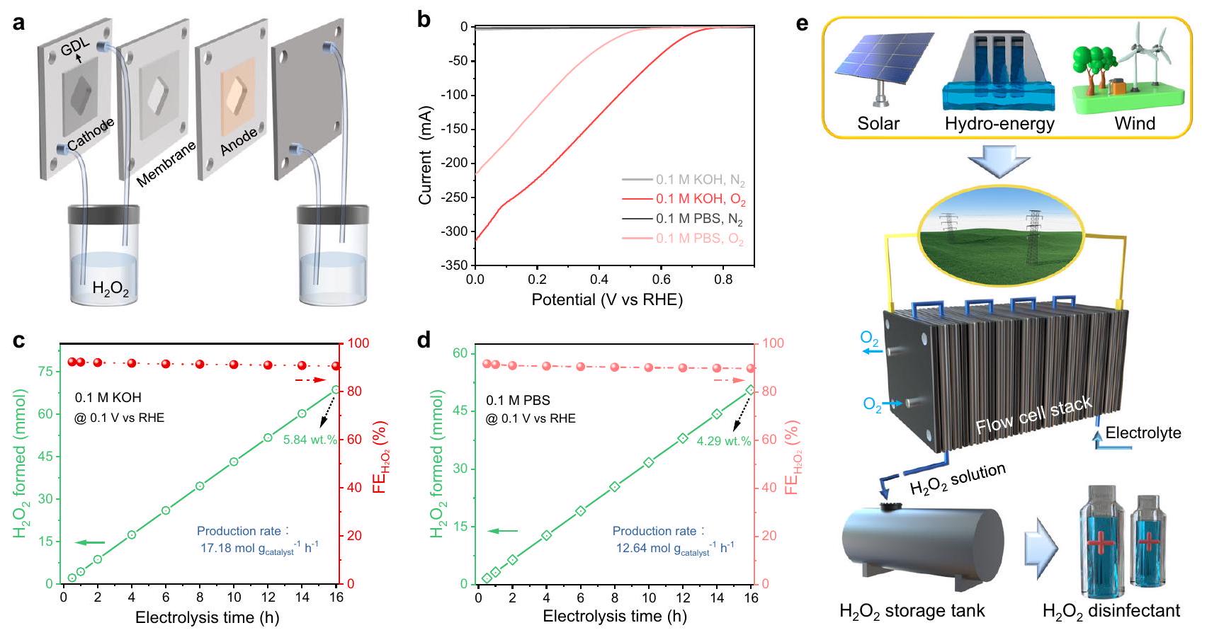
The nanoreactor holds great promise as it emulates the natural processes of living organisms to facilitate chemical reactions, offering immense potential in catalytic energy conversion owing to its unique structural functionality. Here, we propose the utilization of precisely engineered carbon spheres as building blocks, integrating micromechanics and controllable synthesis to explore their catalytic functionalities in two-electron oxygen reduction reactions. After conducting rigorous experiments and simulations, we present compelling evidence for the enhanced mass transfer and microenvironment modulation effects offered by these mesoporous hollow carbon spheres, particularly when possessing a suitably sized hollow architecture. Impressively, the pivotal achievement lies in the successful screening of a potent, selective, and durable two-electron oxygen reduction reaction catalyst for the direct synthesis of medical-grade hydrogen peroxide disinfectant. Serving as an exemplary demonstration of nanoreactor engineering in catalyst screening, this work highlights the immense potential of various well-designed carbon-based nanoreactors in extensive applications.

Natural reactors, such as cells and organelles, provide a micrometerscale hollow space and a suitable internal microenvironment for biochemical processes . Their well-organized interiors enable reactants to be oriented and induced in a regulated way to perform specific functions . Inspired by these cellular structures, various artificial nanoreactors have been designed and synthesized, making them a popular catalytic material for extensive applications . Among them, mesoporous hollow nanoreactors (MHNs) are a novel type of catalytic material. Their unique internal hollow space and mesoporous structure can accommodate complex catalytic processes . In particular, the hollow space in MHNs provides a confined internal microenvironment, allowing for modulation of
molecular catalytic behavior . Additionally, the mesoporous channels could provide the opportunity to control molecular diffusion, adsorption, and surface reactions for tunable catalytic reaction pathway .
The development of MHNs presents challenges in understanding reaction processes at micro/nano interface . Nevertheless, MHNs possess the potential to modulate the reaction process, and its nanoscale structural parameters can be tailored to regulate mass transfer and microenvironment, thereby enabling the tailoring of catalytic reaction pathway . Yet, the effect of structural parameters on overall catalytic kinetics is not fully understood due to the limitations in model material synthesis, which presents a significant
challenge for improving catalytic activity, selectivity, and designing novel catalysts, as well as elucidating reaction mechanisms .
Colloidal carbon spheres are preferred for constructing parametertunable nanoreactors due to their unique advantages, such as adjustable porous structures, controllable particle size, large surface area, and adjustable surface chemistry . Specifically, innovative synthetic methodology tends to provide carbonaceous structures with a wide range of tunability for active sites, such as oxygen-containing functional groups , defects , and edge sites . The properties exhibited by carbon spheres present novel opportunities for screening appropriate probe reactions, such as the electrochemical two-electron oxygen reduction reaction (2e ORR) for hydrogen peroxide ( ) production, and for exploring the operational mechanisms of nanoreactors .
Understanding the operational mechanisms of nanoreactors may drive the on-site electrosynthesis of practical solutions as an oxidant, disinfectant, and emerging energy fuel (Fig. 1a) . In addition, sustainable electro-production eliminates the multi-step, high-energy input, and environmental impacts associated with the traditional anthraquinone (AQ) industry . Efficient electrosynthesis of relies on electrocatalysts that facilitate the highly active pathway . Among the reported electrocatalysts, carbon-based materials have emerged as a promising alternative due to their abundance, low cost, and tunable catalytic properties . To achieve high 2e ORR performance, the surface of carbon material must effectively activate and maintain a suitable binding energy to intermediates . Additionally, the carbon structure should possess a diffusion-friendly geometry to enable rapid separation of the generated from the catalyst layer, preventing its further electroreduction . These challenges pose significant obstacles to the practical implementation of carbon materials for electrochemical 2e ORR. Nevertheless, by employing nano-engineering techniques to
manipulate the structure of carbon sphere materials and harnessing the catalytic functions, including diffusion and microenvironmental modulation within nanoreactors, there is a promising opportunity to overcome these challenges and advance practical strategies for electrosynthesis.
In this work, we proposed the utilization of meticulously controlled carbon spheres as the fundamental building material and employed electrochemical 2e ORR as a diffusion-related probe reaction to validate the catalytic functionality and superior performance of MHNs. The investigation began with finite element simulations (FES) to model the fluid behavior within the mesopores and hollow spaces of MHNs. Through precise tailoring of the internal structures of carbon spheres, a series of carbon-based MHNs was constructed as a proof of concept. The electrochemical properties and simulation results confirmed the enhanced diffusion and microenvironment-modulating effects of MHNs, particularly when designed with an appropriate hollow size. Leveraging these catalytic functionalities of the nanoreactor, the optimized catalysts exhibited impressive activity ( at at pH 7 ) and selectivity ( at at pH 7 ) in electrosynthesis conducted by rotating ring-disk electrode method. Moreover, the successful production of medical-grade disinfectant in a flow cell device highlighted the significant practical potential of nanoreactor engineering. Therefore, our work can serve as a paradigm for advancing the design and understanding of nanoreactor construction and its application in the practical electrochemical production of solutions.

Results

We endeavored to employ engineered carbon spheres to construct MHNs for the purpose of achieving efficient electrosynthesis.
Fig. 1 | Optimization of diffusion-related geometric parameters in MHNs. a-c Schematic diagram of nanoreactor design based on carbon spheres for electrochemical 2e ORR to produce . d Spatial distribution of pressure contours for the mesoporous carbon sphere model ( ). e 3D
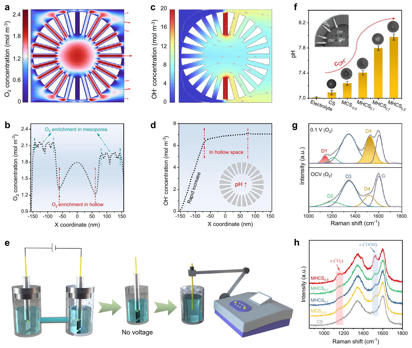
color mapping of the spatial flow velocity distribution on the cross-section. Fluid velocity distribution across mesoporous hollow carbon sphere models ( ) with varying hollow percentage ( , and 0.7 ). Inset in shows flow linear distribution within the hollow mesoporous sphere model.
Such MHNs typically consist of a mesoporous shell layer and an internal hollow, which can be calibrated with several crucial geometric parameters including particle radius ( ), pore size ( ), shell thickness ( ), and hollow radius( ) (Fig. 1b). These structural parameters may alter the fluid dynamics within MHNs, thereby regulating local diffusion and microenvironment, and consequently influencing the reaction process (Fig. 1c).
To investigate the correlation between the nanoreactor architecture and the fluid behavior inside, FES was conducted . To ensure systematic construction of the MHNs and conserve computational resources for investigating the regularity of the electrolyte fluid, we standardized the particle size to 300 nm while maintaining the principle of unique variability for different or . As shown in Supplementary Fig. 1a, b, a mesoporous hollow sphere model ( , ) was constructed in three-dimensional (3D) square space ( ). To simulate fluid flow in an agitated system, the inlet and outlet of the fluid field were set as the left and right sides, respectively (Supplementary Fig. 1c, d). Such a setup generates a decreasing pressure gradient from left to right that drives water to flow spontaneously through the constructed geometry (Supplementary Fig. 2) . Interestingly, there is a noticeable pressure drop inside the mesopores ( ) relative to the surface of the non-porous sphere (Supplementary Figs. 3 and 4). The pressure difference across the mesopores drives water flow through the channels and into the sphere interior, greatly expanding the available catalytic surface by increasing the contact between the electrolyte and carbon surface (Fig. 1d and Supplementary Fig. 5). More interestingly, driven by this pressure difference, a significant fluid acceleration appears in the mesoporous channels ( ), implying an intensified diffusion in MHNs (Supplementary Figs. 6 and 7). The 3D mapping of fluid velocity in the central cross-section ( ) confirms the local diffusion intensification within mesoporous channels and indicates the potential for rapid delivery of and exhaustion of generated (Fig. 1e) .
To evaluate the diffusion effect and identify the optimal solution, a range of pore size parameters ( , and were simulated, along with calculating the fluid velocity distribution at specific locations ( ) to facilitate comparison and analysis (Supplementary Fig. 6b). The highest flow rates were observed in both the inflow and outflow mesopore channels at a pore size of 20 nm , despite the slower flow rate in the mesoporelinked hollow space (Supplementary Fig. 8-10). Based on the above, we continue to maintain similar particle parameters but vary the hollow ratios for predicting fluid mass transfer. So, models with different hollow occupancy ratios ( , and 0.7 ) are also simulated (Supplementary Figs. 9 and 11). The results indicate that a certain size of hollow space is crucial, with the maximum flow velocity in the mesoporous channels occurring at (Fig. 1f). Considering that the active sites for the electrochemical ORR are dispersed on the carbonaceous surface of the mesoporous shells, the localized diffusion enhancement enables the swift inflow of and the rapid transfer of the generated into the bulk solution, thereby averting its accumulation on the catalyst surface and subsequent electro-reduction . These findings indicate that the density of mesopores may influence the fluid behavior within the MHNs. For a single MHN, a small ratio suggests a long mesoporous channel and high mesoporous density, resulting in continuous viscous resistance that affects the flow rate . Conversely, a large implies a short mesoporous channel and a larger hollow structure with lower mesoporous density, enabling rapid fluid entry into the hollow’s flow rate buffer zone, though limiting fluid acceleration. Additionally, the modified MHN model, constructed with reduced mesopore density, demonstrates the electrolyte’s ability to maintain a high flow rate over a long distance (Supplementary Fig. 12). However, the decrease in mesoporous channels would cause most of the electrolyte to flow from the MHN’s surface rather than through the mesopores, potentially reducing the utilization of the internal active
sites. The fluid buffering effects in the hollow region may establish a potentially stable internal microenvironment. To summarize, micromechanical dynamics simulations were employed to identify diffusionfavorable structural parameters ( ) and guide the design of MHNs.

Refinement and characterization of carbon-based MHNs

Inspired by the simulation results above, a sequential organicinorganic hybridization co-assembly approach was developed to fabricate mesoporous hollow carbon sphere-based nanoreactors. As shown in Supplementary Fig. 13, this approach begins with the chronological modular assembly of organic phenolic resin and inorganic silica . In detail, resorcinol and formaldehyde are polymerized under the catalyst of ammonia to form phenolic resins, while tetrapropoxysilane (TPOS) added simultaneously underwent hydrolysis to form . And then, these two components spontaneously co-assemble into the hybrid resin spheres (Supplementary Fig. 14a, b). After further pyrolysis of resin/silica spheres in an inert atmosphere, the resin zone is converted into carbon components, resulting in the formation of spheres (Supplementary Fig. 14c, d). The carbonaceous material in the spheres was selectively eliminated by calcination under an air atmosphere, yielding mesoporous silica spheres ( ) with a solid core, providing compelling evidence that TPOS was initially hydrolyzed to form a core, which was subsequently surrounded by the hybridization of resin and (Supplementary Fig. 15). Thus, the selective removal of component from the spherical precursor led to the formation of mesoporous hollow carbon spheres by generating mesopores and hollow in the areas previously occupied by the phase . The morphology of the was analyzed by SEM and TEM, revealing an average particle radius of 210 nm and a hollow radius of 105 nm , resulting in the designation of (Fig. 2a-e). Further, high-resolution transmission electron microscopy (HRTEM) indicated the permeable mesoporous channels on the external shell (Fig. 2f). Besides, some mesoporous channels running through the shell layer were clearly observed in both the SEM images of the crushed and the locally enlarged TEM images of , providing a path for the electrolyte fluid to pass through the internal hollow space (Supplementary Fig. 16). Additionally, the high-angle annular darkfield scanning transmission electron microscopy (HAADF-STEM) image confirms the hollow mesoporous architecture of , as well as the even distribution of carbon and oxygen elements (Fig. 2g, h). To confirm the flow of electrolyte through the internal hollow space of , we conducted an initial one-hour ORR using in 0.5 M KCl electrolyte. Following the reaction, the samples were dried without washing for direct TEM observation, revealing the presence of residual KCl components filling the interiors of (Supplementary Fig. 17). These findings are further validated by the corresponding elemental linear scans, confirming the presence of mesoporous channels running through the shell layers of and the flow of electrolyte fluids through these channels, enabling movement of electrolyte through the hollow interior (Supplementary Fig. 18).
In the sequential organic-inorganic hybridization co-assembly strategy, the timing of resin and assembly can be flexibly manipulated to significantly adjust the size of the hollow structure of MHCS. We attempted to manipulate the time nodes on formation of resin and to synthesize mesoporous spheres with varying hollow sizes. To achieve this, we added resin monomers (resorcinol and formaldehyde) first, followed by the addition of TPOS after a specific time interval ( ). For the synthesis of , the value of was controlled to be 0 , implying that the resin monomers and the TPOS required for hydrolysis to form were added simultaneously. If TPOS is added 20 min earlier ( ), the hydrolysis process of TPOS
Fig. 2 |Electron microscopy images of synthesized carbon-based MHNs. a Structural model,b,c SEM images,d,e TEM images,f HRTEM image,g HAADF- STEM image,and the corresponding elemental mapping images of
Structural model, ,SEM image,and TEM images of Structural model, SEM image,and TEM images of Structural model, SEM image,and TEM images of MCS
is advanced,leading to the formation of larger solid core before it is hybridized with the resin.After carbonization and removal, with larger hollow size than was synthesized (Fig.2i-l).By delaying the addition of silane by ,the hybridization co-assembly of with resin can be advanced corre- spondingly,resulting in the formation with an ultra-small hollow(Fig. ).Further,by adding the resin monomer for 80 min and then hydrolyzing TPOS( ),a resin solid core is first poly- merized and then surrounded by a hybridization of and resin, resulting in the formation of mesoporous carbon spheres(named MCS )with solid carbon cores and mesoporous carbon shells (Fig.2q-t).The geometrical parameters of the synthesized series of MHCS demonstrated a clear positive correlation between the ratio of hollow size to particle size( )and the value,providing evidence for the controlled synthesis of hollow mesoporous nanoreactors under time order manipulations(Supplementary Table. 1 and Supplemen- tary Fig.19).
Some comparative experiments were also conducted to confirm the role of ,derived from the hydrolysis of TPOS,in the forma- tion of hollow mesoporous carbon spheres.Without the addition of TPOS,only the polymerization of phenolic resin would occur, resulting in the formation of non-mesoporous resin spheres(Sup- plementary Fig.20).Pyrolysis of these resin spheres would then produce microporous carbon spheres(CS,Supplementary Fig.21). Additionally,by burning off the resin components of resin/ spheres assembled at various time intervals( and 80)in the air atmosphere,various mesoporous spherical structures with the topologies opposite to that of the corresponding MHCS and )were obtained(Supplementary Fig.22-24).These findings substantiate the controlled manipulation of hierarchical heterogeneous assembly of and resin in a specific temporal order.
We analyzed the porous structure and physicochemical char- acteristics of five samples: ,and
Fig. 3 | Characterization of as-obtained MHNs. a Nitrogen adsorption-desorption isotherms, pore size distribution curves, XRD patterns, d Raman spectra, e XPS survey spectra, and the corresponding species content of samples.
CS. The nitrogen adsorption and desorption isotherms revealed high Brunauer-Emmett-Teller (BET) specific surface areas (SSA) of 830, 1020 , 1169, and for , and , respectively (Fig. 3a). The Barrett-Joyner-Halenda method revealed the mesopore size distribution of MHCS samples to be in the range of (Fig. 3b). Compared to has a lower specific surface area of only and almost no mesopore distribution (Supplementary Fig. 25). XRD patterns of and CS showed broad peaks at and , corresponding to the (002) and (100) planes of the disordered carbonaceous structure, respectively (Fig. 3c and Supplementary Fig. 26a) . The Raman spectra showed similar intensity ratios of D and G bands and a G linewidth of for all five samples, indicating typical characteristics of amorphous carbon with comparable defects (Fig. 3d and Supplementary Fig. 26b) . XPS analysis revealed an oxygen content of around for (Fig. 3e). The spectrum shows three peaks at 284.6 , 286.0 , and 288.7 eV , corresponding to , and , respectively, while the spectrum exhibits two peaks assigned to and (Supplementary Fig. 27 and Supplementary Fig. 28) . Fig. 3f and Supplementary Table. 2 shows that the distribution of oxygen-containing functional groups, which are considered as active sites for electrochemical 2e , is similar among the different samples. Besides, CS had a similar chemical composition to (Supplementary Fig. 29). In addition, defective carbon or some carbon edges, have been proposed as potential active sites for 2 e ORR in some previous studies . To examine the defective carbon, we utilized electron paramagnetic resonance (EPR) and observed nearly identical signal intensities on , suggesting that exhibits a consistent level of defectivity for electrochemical 2e ORR (Supplementary Fig. 30). These similar properties observed in may be attributed to their shared origin as resorcinol-formaldehyde resin-derived carbon and undergoing the same carbonization process. Therefore, these as-obtain carbon spheres have similar chemical properties and active sites, with differences mainly in hollow size and thickness of
mesoporous shells, making them ideal models for exploring the efficacy of MHNs for catalytic reactions.

Electrocatalytic performance

As a proof of concept, the electrochemical 2e ORR was used as a probe reaction to evaluate catalytic process intensification due to fluid transport in this series of carbon-sphere based MHNs. The electrochemical performance was evaluated using a three-electrode rotating ring-disk electrode (RRDE) technique at 1600 rpm in an -saturated electrolyte, with the Pt ring electrode set at 1.2 V vs reversible hydrogen electrode (RHE) to detect the produced on the disk. Remarkably, the achieves a large diffusion-limiting disk current density ( at 0.20 V vs RHE) in , approaching the theoretical limit for ORR (Fig. 4a) . Besides, the delivers a high onset potential of 0.85 V vs RHE, larger than the thermodynamic equilibrium ORR potential . The high ORR onset potential may stem from its appropriate porous structure and geometric framework, which enhance contact with electrolyte fluids to improve the utilization of carbon surface active sites in the electrolyte environment . Correspondingly, the electrochemical activity of non-mesoporous CS was found to be poor, as indicated by a very low disk current densities at diffusion-limiting conditions, suggesting the insufficient the exposure of active sites in the micropores (Supplementary Fig. 31). Figure 4b, c shows the calculated selectivity and the corresponding electron transfer number ( ) for samples. The catalyst delivers the high selectivity ( ) and a value around 2.05 across a wide potential window ( , from 0.3 V to 0.8 V vs RHE), which are superior to those of most of the previously reported catalysts (Supplementary Table. 3). Decreases in selectivity were observed in the order of , and , showing a positive relationship with the simulated flow rate in the mesopore channels of the corresponding MHNs models.
To comprehend the distinctions in the electrochemical properties of , it is imperative to uncover the intrinsic active sites involved
Fig. 4 | Electrochemical performance of MHNs. a LSV curves of RRDE measurements at 1600 rpm in the corresponding selectivity, and c electron transfer number at various applied potentials. d Tafel plots derived from LSV curves in 0.1 M KOH . e Normalized electrochemical activity and partial current on (@ 0.6 V vs RHE), along with the corresponding selectivity and electrolyte inflow velocity. f Schematic diagram depicting the flow of fluid/
oxygen and the oxygen reduction process on the model. Stability measurements of at a fixed disk potential of 0.5 V vs RHE in 0.1 M KOH . h LSV curves of MHCS before and after 12 h stability test. i LSV curves of RRDE measurements at 1600 rpm in 0.1 M PBS, the corresponding selectivity, and electron transfer number at various applied potentials.
in electrocatalytic ORR. We reduced the sample in a mixed atmosphere to eliminate the oxygen component, resulting in R-MHCS with an oxygen content as low as (Supplementary Fig. 32a). Consequently, the ORR activity and selectivity of
R-MHCS were significantly reduced (Supplementary Fig. 32b), indicating that the oxygen species on the carbon matrix serve as the active source of ORR, consistent with some previous reports . Given the comparable oxygen species on , the notable discrepancy in
selectivity is attributed to the fluid behavior of electrolytes within different architectures of MHNs. Fig. 4d displays the Tafel slopes of MHCS , with MHCS exhibiting a low value of 73 mV dec , indicating its fast reaction kinetics. Tafel plots reflect various rate-determining steps (RDS), and a progressive decrease in Tafel slopes could indicate a shift in the RDS from the first electron-transfer step ( , ) to the last desorption step ( , . The ORR pathway was studied from the perspective of the reduction reaction ( ) activity in -saturated 0.1 M KOH containing . Among exhibits apparent inertness to , with negligible currents, confirming its highly selective 2e pathway (Supplementary Fig. 33). In contrast, we observed an increasing trend in current from , to MCS-0.5, suggesting an improved capability. Considering the simulated fluid velocity on , we deduce that the low flow rates would advance the indirect 4 e pathway to reduce the selectivity .
These carbon sphere-based electrocatalyst were further evaluated for their accessible active surface area (ECSA) using a double-layer capacitance ( ) method. Specifically, the values for , , and were calculated to be 8.04, 7.20, 4.36, and 3.17, respectively (Supplementary Fig. 34, 35). Interestingly, the values of MHCS do not align with their total BET surface area, but instead, exhibit a positive correlation with the external surface area excluding the microporous region (Supplementary Fig. 35b) . Considering the particle morphology of , it can be hypothesized that the internal surface exposure, facilitated by the mesoporous channels, enhances the interaction between the electrolyte and active sites, thereby promoting heightened electrocatalytic activity . Prominently, the high value on signifies its structurally favorable diffusion, suggesting a swift supply of electrolyte ions and effective utilization of active sites. Besides, the non-mesoporous CS exhibits a low of , further illustrating the restricted accessibility of micropores by electrolytes (Supplementary Fig. 36 . Furthermore, we utilized ECSA to standardize the electrochemical activity and the partial currents of at diffusion-related potentials ( 0.6 V vs RHE), as illustrated in Fig. 4e. Interestingly, the associated normalized currents and 2 e selectivity exhibit a positive correlation with the simulated electrolyte inflow velocity, providing additional evidence for the connection between the diffusion effect and the electrochemical performance on these MHNs. These characteristics demonstrate the influence of the hollow’s structural parameters on diffusion and their reflection on electrocatalytic performance (Fig. 4f).
To assess the catalytic stability, we conducted chronoamperometric tests for using the RRDE technique at a constant disk potential of 0.5 V vs RHE. During the continuous testing, the accumulated might lead to a slight rise in the ring current and subsequently in selectivity. To maintain a consistent ring current, we replaced the electrolyte every 3 h and performed electrochemical cleaning of the Pt ring to remove any effects of the accumulated during continuous operation. The results showed that the MHCS catalyst maintained stable disk/ring currents and achieved over 95% selectivity throughout the 12 -hour continuous test (Fig. 4 g ). Further, we conducted an accelerated durability test (ADT) on by sweeping the potential between 0.2 and 1.0 V vs RHE for 12 h . The similar linear sweep voltammetry curves obtained before and after ADT confirm its high stability (Fig. 4h). After long-term electrolysis, still maintains its hollow mesoporous structure, and its chemical composition remains consistent with its pre-reaction state, ensuring its stability and reusability (Supplementary Figs. 37 and 38). Of particular interest, demonstrates exceptional 2e- ORR performance in neutral electrolyte conditions ( pH 7 ), with a diffusionlimited disk current of at 0.2 V vs RHE, an onset potential of 0.6 V vs RHE, and an selectivity exceeding , surpassing vast
majority of carbon-based catalysts reported in the literature (Fig. 4i-k and Supplementary Table. 4). The trends observed in the ORR activity and selectivity of under neutral conditions were consistent with those observed under alkaline conditions. Interestingly, the polarization curves exhibit two distinct sets of slopes at different potentials, suggesting variations in the ORR mechanism. Consistently, the test conducted on revealed a low current density, indicating its overall inertness to in a neutral electrolyte, with a slight increase observed at more negative potentials (Supplementary Fig. 39). This trend in the current aligns with that of the ORR, highlighting the influence of the indirect 4 e process at relatively high voltages on the 2e selectivity .

Actual electrosynthesis properties

The practical application of catalysts was evaluated using a H-type cell setup in 0.1 M KOH with continuous bubbling (Supplementary Fig. 40a). The produced was quantified by the titration method with the ultraviolet-visible (UV-vis) spectrophotometric technique. During a long-term stability test at a fixed voltage of 0.5 V vs RHE, the current remains stable at about and the concentration of accumulated increases continuously, resulting in within 12 h (Supplementary Fig. 40b). During the long-term continuous test, the fluctuations of current and Faraday efficiency (FE) (> 97%) are slim, indicating the reliable practicality of the bulk electrocatalyst.
To address the limitations of peroxide generation in a static H -cell configuration, characterized by inefficient mass transport due to low diffusion efficiency and desorption rate, leading to suboptimal apparent productivity, we further evaluated the actual production from using a flow cell setup (Fig. 5a and Supplementary Fig. 41). In the measurements, a loaded carbon paper (CP) electrode, including a gas diffusion layer (GDL), was used as the cathode, and a commercial served as the anode in the flow cell. As depicted in Fig. 5b, exhibited a sharp increase in current density with rising voltage, reaching in 0.1 M KOH and in 0.1 M phosphate buffered solution (PBS) at an uncompensated voltage of 0.1 V vs RHE. Moreover, the current of showed a consistent and steady profile during continuous electrolysis at an applied voltage of 0.1 V vs RHE (Supplementary Fig. 42). Notably, the production yield of exhibited a steady increase over time, with a 16-hour cumulative yield of reaching 68.7 mmol in 0.1 M KOH and 50.6 mmol in 0.1 M PBS, corresponding to production rates of 17.18 and (Fig. 5c, d) and outperforming most recently reported electrocatalysts (Supplementary Table. 5). Additionally, the Faraday efficiency of electrosynthesis on remained consistently around throughout a long-term test. After 16 h of electrosynthesis in the flow cell, the cumulative concentration of reached in an alkaline environment and in a neutral medium, satisfying the concentration requirements for the medical-grade disinfectant ( . Notably, the electroproduction of solutions in neutral electrolytes is particularly appealing due to its environmental friendliness, minimal corrosiveness, and potential for reduced electrolytic cell costs . Additionally, neutral solutions provide a sustainable and versatile option for practical applications, including the direct use of synthesized in biochemical systems . The robust performance and excellent selectivity for 2e reduction demonstrated by in the flow cell setup validate its potential for practical applications in electrochemical production, particularly for the electro-production of neutral solutions . In contrast, exhibited restricted electrochemical activity, with currents of 51 mA at 0.1 M KOH and 25 mA at 0.1 M PBS at an applied potential of 0.1 V vs RHE (Supplementary Fig. 43a). Additionally, the FE of for electroproduction is approximately , significantly lower than that of the electrode (Supplementary Fig. 43b, c). This noticeable
Fig. 5 | Actual electro-production based on MHNs. a Schematic diagram of the flow cell for electrosynthesis. Polarization curves of loaded CP electrode in flow cell. c Electrolysis time-dependent production and faradaic efficiency of under continuous purging in 0.1 M KOH . d Electrolysis
time-dependent production and faradaic efficiency of under continuous purging in 0.1 M PBS. e Envisioned green electricity-driven large-scale electrochemical production of disinfectant.
distinction in electrochemical performance further underscores the effectiveness of the engineered carbon sphere-based MHNs.
Based on the remarkable activity, high selectivity, and reliable stability of , coupled with the global goal of carbon neutrality, we envision a future where large-scale production of disinfectants is achieved using sustainable energy sources . As depicted in Fig. 5e, surplus green electricity generated from solar, hydro, and wind energy sources is utilized as the energy supply for decentralized production in an electrolytic cell stack. Significantly, the medical-grade solution produced under neutral conditions can be elegantly stored or directly employed for disinfection and sterilization purposes. This green electricity-driven disinfectant production represents a sustainable approach that enables on-site production and utilization of , circumventing the pollution, high energy consumption, and explosion hazards associated with the traditional AQ industry. In the pursuit of this goal, the nanoreactor engineered carbon spheres will serve as pivotal catalysts in realizing this vision.

Microenvironmental modulation effect of nanoreactors

To gain a deeper understanding of the exceptional 2e ORR performance of , particularly in neutral conditions, we conducted extensive simulations to elucidate the catalytic mechanism of the hollow mesoporous nanoreactor. To provide a visual representation of the interior within the nanoreactor, a two-dimensional (2D) model of a hollow mesoporous sphere ( ) was constructed . As shown in Supplementary Fig. 44, the mesoporous hollow sphere is modeled as having all surfaces as catalytically active sites and placed within a square simulation domain ( ), with the inflow and outflow boundaries for the electrolyte set at the left and right sides. Consistent with the results of the previous 3D simulations, the -containing electrolyte fluid is driven by the pressure gradient to flow through the mesopore-hollow-mesopore of the sphere and ultimately exits the simulation domain (Supplementary Fig. 45). We obtained the velocity distribution at and observed a
significant acceleration of the fluid flow in the mesopore region, while the flow velocity within the hollow region was relatively low (Supplementary Fig. 46). High flow rates can increase the entrainment of per unit time, as evidenced by the spatial concentration distribution of being almost proportional to the flow rate distribution, leading to the enrichment of in pore channels (Fig. 6a, b). From a reaction kinetics perspective, the local enrichment of in the mesoporous channels can promote the activation of and stimulate the formation of as well as the consumption of protons to generate . The accumulation of generated, which serves as a flow buffer, causes a local pH elevation within the MHNs, as confirmed by the finite element simulation results (Fig. 6c, d). After the electrolysis in neutral media ( ), phenolphthalein indicator was quickly dropped onto the electrode and inserted into a bottle containing neutral electrolyte. The appearance of a slight purplish red color on the electrolytic surface was observed, providing evidence for the presence of a localized pseudo-alkaline microenvironment (Supplementary Fig. 47). More directly, a significant in-situ color change was observed on electrode surface during a 2e ORR in neutral electrolyte ( ) containing phenolphthalein (Supplementary Fig. 48). This color change and the electrocatalytic process proceeded almost simultaneously, providing evidence of a local pH increase near the catalyst layer (Supplementary Movie 1). Next, we conducted the following experiments to verify the MHNs ‘ ability to accumulate OH . Initially, as shown in Fig. 6e, the ORR process was performed for 10 min in a neutral electrolyte using a carbon sphere catalyst at 0.4 V vs. RHE, with the corresponding current density recorded in Supplementary Fig. 49a. Subsequently, all electrodes were extracted from the cell, and the working electrode was rinsed by immersion in 5 mL of an aqueous solution. This process was repeated 10 times, and the pH of the aqueous solution was measured. Fig. 6 f illustrates that the electrode surfaces exhibited higher concentrations compared to the other samples. This observation is associated with the high current density generated by the electrodes, leading to increased
Fig. 6 | Microenvironmental modulation in MHNs. a Spatial distribution of concentration in the mesoporous carbon sphere model ( , ), and the corresponding concentration distribution curve of mesoporous carbon sphere model on . c Spatial distribution of concentration of the mesoporous carbon sphere model ( , ), and the corresponding concentration distribution curve of
mesoporous carbon sphere model on . e Schematic diagram of the process for testing the concentration on the electrode surface. Comparison of concentrations on the surface of In-situ Raman spectra of electrode at open circuit voltage and applied potential ( 0.1 V vs RHE) in 0.1 M PBS.
h Comparison of in-situ Raman spectra on electrode at applied potential ( 0.1 V vs RHE).
production of by-products. Additionally, it was observed that there is no linear relationship between the current densities and measured concentrations for each carbon sphere electrode (Supplementary Fig. 49b, c). Rather, the electrode with the hollowstructured carbon sphere exhibited a significantly higher concentration. Therefore, we attribute the localized accumulation on the electrode to the combined effects of its high electrochemical activity and favorable hollow geometric configuration. These results provide experimental evidence that supports the simulation results discussed above.
To investigate the effect of enrichment and local pH elevation on the 2 e ORR within the carbon sphere-based MHNs, we utilized insitu Raman spectroscopy to probe the catalyst-adsorbate interactions ( ). In an oxygen atmosphere, the Raman spectra of a electrode at the open-circuit voltage (OCV) and an applied potential of 0.1 V vs RHE are shown in Fig. 6g. The D band was fitted by the characteristic modes of D1, D2, D3, and D4 at ~1130, 1200, 1340, and , respectively . Compared with the OCV, the D peak widened and a D1 peak emerged, which reflects the adsorption of , and a
corresponding sharper D4 peak indicates a greater formation of *OOH intermediate . This phenomenon can be inferred as follows: the enrichment of and localized pH elevation in the MHNs accelerate the reaction rate, facilitating the activation of , stabilizing intermediates, and inhibiting the protonation process of *OOH intermediates ( ) associated with the pathway, thereby promoting generation . As illustrated in Fig. 6h, the comparison of the in-situ Raman spectra of all the samples revealed the most pronounced O-O stretching vibrations ( and ) signals on the , indicating the accelerated reaction rate within the dominant conformation featuring favorable reaction microenvironments.
We present a summary on the functional attributes of the mesoporous hollow carbon sphere nanoreactor in the electrochemical 2e ORR. The mesoporous channels facilitate fluid acceleration to transport the generated into the bulk solution, decreasing the likelihood of its further electro-reduction on the catalyst surface . Besides, the accelerated electrolyte flow rapidly pumps substrates to enrich . Additionally, the accelerated reaction rate and favorable
hollow configuration promote localized pH elevation, providing a suitable microenvironment for the 2e ORR. FES, experimental results, and in-situ Raman spectroscopy verify these functions of the MHNs based on engineered carbon spheres, which can be compared to certain structural functions of cells: the mesoporous shell of the MHNs is analogous to the cell membrane and effectively controls the entry and exit of substrates and products; while the hollow interior of the MHNs, akin to the cytoplasm within cells, furnishes a conducive internal microenvironment for the reaction. Whilst our example may lack the intricate and sophisticated functional units found in biology, it nonetheless serves as a source of inspiration for the construction of nanoreactors through biomimicry.

Discussion

In summary, this work explored the catalytic functionalities of carbon-based MHNs. In detail, we engineered the interiors of mesoporous carbon spheres, drawing inspiration from FES for fluid diffusion, thereby constructing a series of model nanoreactors. By utilizing electrochemical 2e ORR as a probe reaction, we provide evidence of the enhanced diffusion, reactant enrichment, and microenvironmental modulation facilitated by the mesoporous hollow architectures. These catalytic functionalities are closely linked to the structural parameters of MHNs, emphasizing the importance of controlling the nanoreactor’s microstructure for targeted reactions. With the catalytic functionalities of the nanoreactor, the optimized catalysts demonstrate impressive activity and selectivity in electrosynthesis under both alkaline and neutral conditions. Moreover, the generation of medical-grade disinfectant in a flow cell device substantiates the significant practical potential of this nanoreactor engineering. Overall, this study showcases the successful implementation of nanoreactor engineering in screening catalysts with functional orientation, paving the way for a wide range of nanoreactor applications.

Methods

Synthesis of mesoporous carbon sphere nanoreactors with different internal structures

In a typical synthesis, a solution of 65 mL of ethanol and 15 mL of was mixed with 2.5 mL of and 0.8 mL of formaldehyde at room temperature. Subsequently, 0.6 g of resorcinol and 6 mL of TPOS were added to the mixed solution under stirring. The reaction was stirred for 24 h at room temperature, and the products were obtained by centrifugation, followed by washing with water and ethanol, and drying in an oven. The as-obtained products were subjected to pyrolysis at a temperature of for 2 h in with a heating rate of , followed by removal of the silica template through etching with . The internal structure of the carbon spheres is determined by the temporal order of addition of resorcinol and TPOS. , and were synthesized by adding resorcinol and TPOS at intervals of , and 80 min , respectively. CS were prepared without the addition of TPOS. The reduction of was conducted in a tube furnace at for 2 h under a mixed atmosphere, resulting in the product denoted as .

Material characterizations

Scanning electron microscopy (SEM) images were acquired using a scanning microscope (SU8230, Japan). Transmission electron microscopy (TEM) was performed with Tecnai G2 F30 (America) and JEM2100 (Japan). Powder X-ray diffraction data were obtained using a Rigaku D/Max2500PC diffractometer with radiation ( ) across the range of , with a scan speed of at room temperature. Raman measurements were conducted using a spectrometer (NanoWizard Ultra Speed & inVia Raman) with a laser having an excitation wavelength of 532 nm . Nitrogen sorption
isotherms were recorded at 77 K (Tristar 3020, USA). X-ray photoelectron spectroscopy (XPS) data were collected with a monochromatic Al source (KRATOS, Axis Ultra). Electron paramagnetic resonance (EPR) measurements were carried out using a Bruker ECSEMX X-band EPR spectrometer at room temperature.

Electrochemical measurements

All electrochemical measurements were conducted using an electrochemical workstation (PARSTAT 3000A-DX) with a three-electrode cell at room temperature. An Ag/AgCl electrode was used as reference electrode and equipped with a salt bridge to eliminate liquid boundary potentials and prevent cross-contamination between the solution of the study system and the reference electrode system. Additionally, a Pt sheet was employed as the counter electrode, and a catalyst-loaded rotating ring-disk electrode (RRDE) functioned as the working electrode. The RRDE assembly included a glassy carbon rotation disk electrode (disk area: ) and a Pt ring (ring area: ) with a collection efficiency ( ) of 0.37.
In the preparation of the catalyst ink, 5.0 mg of the electrocatalyst was dispersed in of ethanol and of a Nafion solution. After ultrasonic treatment for of the catalyst ink was drop-cast onto the disk electrode.
The electrochemical measurements were conducted at room temperature in -saturated 0.1 M KOH aqueous solution ( pH 13 ) and . The working electrode rotated at a constant speed of 1600 rpm during the tests. All potentials were converted to reference the reversible hydrogen electrode (RHE) using the following equation:
Stable linear sweep voltammetry (LSV) was performed at a scan rate of in electrolytes saturated with and . To ensure the complete oxidation of , the ring electrode was maintained at a constant potential of 1.2 V vs RHE. The selectivity of and the electron transfer number ( ) were calculated were calculated based on the disk current ( ) and ring current ( ) as following equations:

Measurement of electrochemically active surface area

The electrochemically active surface area (ECSA) was determined using the double-layer capacitance method. Constant potential cyclic voltammetry (CV) scans were performed in the double-layer region, ranging from -0.06 to 0.04 V vs , with scan rates of 20,40 , 60,80 , and . Plotting the sweep speed as the abscissa and ( ) as the ordinate, the slope value was calculated to represent the double-layer capacitance ( ), which is linearly related to ECSA. ECSA was determined by calculating using the following equations:
Where the specific capacitance ( ) for the electrode surface, typically falling within the range of 20 to . Specifically, we adopted a value of denotes the electrode surface area.

Bulk electrolysis

The bulk electrosynthesis of in 0.1 M KOH was conducted using a customized H -cell electrolyzer to further investigate the practical
performance of electrosynthesis. The working electrode employed was a carbon-paper electrode ( ) coated with . As for the counter and reference electrodes, a Pt electrode and an (saturated KCl ) electrode were utilized, respectively. Chambers were separated by a Nafion membrane. The electrolyte consisted of -saturated 0.1 M KOH aqueous solution.

Direct detection of the local pH changes on electrode

For the indirect observation of changes in local pH , the catalyst was employed to facilitate the 2 e ORR process for 10 min in the electrolytic cell ( 0.1 M PBS, vs RHE). Subsequently, the applied voltage was switched off, and the working electrode was transferred to 5 mL of aqueous solution and rinsed. After repeating these two steps 10 times, the pH value was measured in the reagent bottle using a pH meter. To ensure experimental accuracy, this parallel experiment was conducted 5 times.
For a direct observation of pH elevation on the electrode surface, we monitored the color change on the electrode surface during the ORR at 0.1 V vs RHE. The reaction was conducted in a H-type electrolytic cell using containing 1 mg of phenolphthalein as the electrolyte for visualization.

yield in the flow cell

The electrochemical synthesis of via ORR was carried out using a two-compartment flow cell setup separated by a Nafion membrane. The cathode assembly in the gas diffusion layer was created by applying the catalyst ink onto the carbon paper, with an actual working area of and a catalyst loading of . was employed as the reference electrode, and served as the anode. In the flow cell test, a PBS electrolyte was circulated through each compartment at a flow rate of , while the cathode received a continuous supply of at a rate of .

concentration measurement

The amount of was determined using a conventional cerium sulfate titration method, following the equation:
In this method, yellow is reduced by to colorless . A solution was typically prepared by dissolving in 100 mL of acid solution. The calibration curve was established by linear fitting of absorbance values at a wavelength of 320 nm for known concentrations of 0.01, 0.02, , and . Using this calibration curve, the concentration of reduced in the sample solution was determined by measuring UV-vis absorption intensity (Supplementary Fig. 50). Finally, the yield was calculated based on the known concentration of reduced . The faradaic efficiency (FE) for generation is calculated as the following equation:

Finite element simulation

A simulation was conducted using COMSOL Multiphysics software to investigate the relationship between electrolyte flow and mass transport in the mesoporous hollow nanoreactor (MHN) model, accounting for the convective and diffusive effects of , and OH . Both 3D and 2D models were employed to simulate the flow rate and material distribution in the MHNs, respectively.
To model the synthesized MHCS , MHNs were constructed uniformly with a particle radius of 150 nm and a mesopore channel of approximately 20 nm , with the proportion of the hollow component as the sole variable. This approach effectively illustrates the impact of various ratios on fluid transport at a standardized particle size, optimizing computational efficiency without compromising accuracy. Additionally, models with different pore sizes were simulated and compared. For simplicity, deformation was disregarded, and the model was assumed to be in a fixed position. Two 10 nm spaces were established on the left and right sides of the mesoporous channel to simulate the inflow and outflow of substances in the nonporous structure. The simulation model employed axisymmetric geometry to calculate fluid velocity and pressure in the mesoporous and hollow regions, as well as the concentration distribution of reactant substances. In this model, the left and right sides were designated as the inlet and outlet of the electrolyte, respectively, with mass transfer driven by fluid flow and concentration diffusion. The governing equations are as follows:
where the dependent variables are velocity ( ), pressure ( ), and concentration ( ). is the fluid density, is the fluid viscosity, is the diffusion coefficient of substance i , and is the reaction rate. For the 3D/2D model of MHNs, electrolyte ingress occurs from the left, traverses the model region, and egresses from the right. To emulate the flow induced by solution rotation, the inlet velocity was set to , with a zero-pressure boundary condition at the outlet. Given the low Reynolds number regime ( ) resulting from the small size of , the “Laminar Flow” module was chosen to simulate the flow field. At the model’s inlet boundary, a solution saturated with was set, having a concentration of at the top inflow boundary. The outflow boundary was configured with a diffusion flux set to 0 . The model’s surface was designated as the location where the reaction occurs, and is consumed for conversion. Throughout the simulation, we examined the impacts of geometric dimensions, such as mesopore diameter and spacing, on and concentrations. The geometric parameters required for the simulation were derived from experimental data, including electron microscope images.

Data availability

The main data supporting the findings of this study are available within the main text and the Supplementary Information file. The main data generated in this study have been deposited in the figshare database under the accession code https://doi.org/10.6084/m9.figshare. 24935178.

References

  1. Vriezema, D. M. et al. Self-assembled nanoreactors. Chem. Rev. 105, 1445-1490 (2005).
  2. Yu, Z. et al. Kinetics driven by hollow nanoreactors: an opportunity for controllable catalysis. Angew. Chem. Int. Ed. 62, e202213612 (2023).
  3. Petrosko, S. H., Johnson, R., White, H. & Mirkin, C. A. Nanoreactors: small spaces, big implications in chemistry. J. Am. Chem. Soc. 138, 7443-7445 (2016).
  4. Marguet, M., Bonduelle, C. & Lecommandoux, S. Multicompartmentalized polymeric systems: towards biomimetic cellular structure and function. Chem. Soc. Rev. 42, 512-529 (2013).
  5. Weiss, M. et al. Sequential bottom-up assembly of mechanically stabilized synthetic cells by microfluidics. Nat. Mater. 17, 89-96 (2018).
  6. Wang, G.-H. et al. Platinum-cobalt bimetallic nanoparticles in hollow carbon nanospheres for hydrogenolysis of 5-hydroxymethylfurfural. Nat. Mater. 13, 293-300 (2014).
  7. Zhu, W. et al. Functionalization of hollow nanomaterials for catalytic applications: nanoreactor construction. Adv. Mater. 31, 1800426 (2019).
  8. Ding, S. et al. Formation of hollow nanospheres inside mesoporous silica nanoreactors. J. Am. Chem. Soc. 133, 21-23 (2011).
  9. Tian, H. et al. Construction of hollow mesoporous silica nanoreactors for enhanced photo-oxidations over Au-Pt catalysts. Nat. Sci. Rev. 7, 1647-1655 (2020).
  10. Yu, Z. et al. Ruthenium-nanoparticle-loaded hollow carbon spheres as nanoreactors for hydrogenation of levulinic acid: explicitly recognizing the void-confinement effect. Angew. Chem. Int. Ed. 60, 20786-20794 (2021).
  11. Dong, C. et al. Hollow carbon sphere nanoreactors loaded with PdCu nanoparticles: void-confinement effects in liquid-phase hydrogenations. Angew. Chem. Int. Ed. 59, 18374-18379 (2020).
  12. Yu, Q. et al. Space-confined carbon-doped Pd nanoparticles as a highly efficient catalyst for selective phenol hydrogenation. ACS Catal. 13, 3925-3933 (2023).
  13. Tian, Q. et al. Exceptional photocatalytic hydrogen peroxide production from sandwich-structured graphene interlayered phenolic resins nanosheets with mesoporous channels. Adv. Funct. Mater. 33, 2213173 (2023).
  14. Tang, . et al. Carbon nanocage with maximum utilization of atomically dispersed iron as efficient oxygen electroreduction nanoreactor. Adv. Mater. 35, 2208942 (2023).
  15. Hung, C.-T. et al. Gradient hierarchically porous structure for rapid capillary-assisted catalysis. J. Am. Chem. Soc. 144, 6091-6099 (2022).
  16. Yu, Z. et al. Metal-loaded hollow carbon nanostructures as nanoreactors: microenvironment effects and prospects for biomass hydrogenation applications. ACS Sustain. Chem. Engin. 9, 2990-3010 (2021).
  17. Xie, G., Zhang, J. & Ma, X. Compartmentalization of multiple catalysts into outer and inner shells of hollow mesoporous nanospheres for heterogeneous multi-catalyzed/multi-component asymmetric organocascade. ACS Catal. 9, 9081-9086 (2019).
  18. Li, X. et al. Amorphous NiFe oxide-based nanoreactors for efficient electrocatalytic water oxidation. Angew. Chem. Int. Ed. 62, e202300478 (2023).
  19. Wang, X. et al. Balancing mass transfer and active sites to improve electrocatalytic oxygen reduction by B, N Codoped C nanoreactors. Nano Lett. 23, 4699-4707 (2023).
  20. Boyjoo, Y. et al. Engineering nanoreactors for metal-chalcogen batteries. Energy Environ. Sci. 14, 540-575 (2021).
  21. Swisher, J. H., Jibril, L., Petrosko, S. H. & Mirkin, C. A. Nanoreactors for particle synthesis. Nat. Rev. Mater. 7, 428-448 (2022).
  22. Tian, H., Liang, J. & Liu, J. Nanoengineering carbon spheres as nanoreactors for sustainable energy applications. Adv. Mater. 31, 1903886 (2019).
  23. Liu, J., Wickramaratne, N. P., Qiao, S. Z. & Jaroniec, M. Molecularbased design and emerging applications of nanoporous carbon spheres. Nat. Mater. 14, 763-774 (2015).
  24. Wang, T., Okejiri, F., Qiao, Z. A. & Dai, S. Tailoring polymer colloids derived porous carbon spheres based on specific chemical reactions. Adv. Mater. 32, 2002475 (2020).
  25. Chen, S. et al. Chemical identification of catalytically active sites on oxygen-doped carbon nanosheet to decipher the high activity for electro-synthesis hydrogen peroxide. Angew. Chem. Int. Ed. 133, 16743-16750 (2021).
  26. Lim, J. S. et al. Designing highly active nanoporous carbon production electrocatalysts through active site identification. Chemistry 7, 3114-3130 (2021).
  27. Wang, Z. et al. Hydrogen peroxide generation with faradaic efficiency on metal-free carbon black. ACS Catal. 11, 2454-2459 (2021).
  28. Wang, W., Zheng, Y., Hu, Y., Liu, Y. & Chen, S. Intrinsic carbon defects for the electrosynthesis of . J. Phys. Chem. Lett. 13, 8914-8920 (2022).
  29. San Roman, D. et al. Engineering three-dimensional (3D) out-ofplane graphene edge sites for highly selective two-electron oxygen reduction electrocatalysis. ACS Catal. 10, 1993-2008 (2020).
  30. Sa, Y. J., Kim, J. H. & Joo, S. H. Active edge-site-rich carbon nanocatalysts with enhanced electron transfer for efficient electrochemical hydrogen peroxide production. Angew. Chem. Int. Ed. 58, 1100-1105 (2019).
  31. Ding, Y. & Qiao, Z. A. Carbon surface chemistry: new insight into the old story. Adv. Mater. 34, 2206025 (2022).
  32. Li, Z., Li, B., Yu, C., Wang, H. & Li, Q. Recent progress of hollow carbon nanocages: general design fundamentals and diversified electrochemical applications. Adv. Sci. 10, 2206605 (2023).
  33. Xia, C., Xia, Y., Zhu, P., Fan, L. & Wang, H. T. Direct electrosynthesis of pure aqueous solutions up to by weight using a solid electrolyte. Science 366, 226-231 (2019).
  34. Jiang, Y. et al. Selective electrochemical production through two-electron oxygen electrochemistry. Adv. Energy Mater. 8, 1801909 (2018).
  35. Zhou, Y., Chen, G. & Zhang, J. A review of advanced metal-free carbon catalysts for oxygen reduction reactions towards the selective generation of hydrogen peroxide. J. Mater. Chem. A 8, 20849-20869 (2020).
  36. Sun, Y., Han, L. & Strasser, P. A comparative perspective of electrochemical and photochemical approaches for catalytic production. Chem. Soc. Rev. 49, 6605-6631 (2020).
  37. Tian, Z. et al. Constructing interfacial boron-nitrogen moieties in turbostratic carbon for electrochemical hydrogen peroxide production. Angew. Chem. Int. Ed. 134, e202206915 (2022).
  38. Hu, C., Paul, R., Dai, Q. & Dai, L. Carbon-based metal-free electrocatalysts: from oxygen reduction to multifunctional electrocatalysis. Chem. Soc. Rev. 50, 11785-11843 (2021).
  39. Bu, Y. et al. Carbon-based electrocatalysts for efficient hydrogen peroxide production. Adv. Mater. 33, 2103266 (2021).
  40. Jiang, K., Zhao, J. & Wang, H. Catalyst design for electrochemical oxygen reduction toward hydrogen peroxide. Adv. Funct. Mater. 30, 2003321 (2020).
  41. Li, L. et al. Tailoring selectivity of electrochemical hydrogen peroxide generation by tunable pyrrolic-nitrogen-carbon. Adv. Energy Mater. 10, 2000789 (2020).
  42. Perry, S. C. et al. Electrochemical synthesis of hydrogen peroxide from water and oxygen. Nat. Rev. Chem. 3, 442-458 (2019).
  43. Jing, L. et al. Mesoscale diffusion enhancement of carbon-bowl-shaped nanoreactor toward high-performance electrochemical production. ACS Appl. Mater. Inter. 13, 39763-39771 (2021).
  44. Deng, Z., Gong, M., Gong, Z. & Wang, X. Mesoscale mass transport enhancement on well-defined porous carbon platform for electrochemical synthesis. Nano Lett. 22, 9551-9558 (2022).
  45. Park, J., Nabae, Y., Hayakawa, T. & Kakimoto, M. A. Highly selective two-electron oxygen reduction catalyzed by mesoporous nitrogendoped carbon. ACS Catal. 4, 3749-3754 (2014).
  46. Grunberg, L. & Nissan, A. H. Mixture law for viscosity. Nature 164, 799-800 (1949).
  47. Zhang, H. et al. Surfactant-free assembly of mesoporous carbon hollow spheres with large tunable pore sizes. ACS Nano 10, 4579-4586 (2016).
  48. Mei, S. C. et al. Sequential assembly tailored interior of porous carbon spheres for boosted water decontamination through peroxymonosulfate activation. Adv. Funct. Mater. 32, 2111184 (2022).
  49. Xie, L. et al. Kinetics-controlled super-assembly of asymmetric porous and hollow carbon nanoparticles as light-sensitive smart nanovehicles. J. Am. Chem. Soc. 144, 1634-1646 (2022).
  50. Tian, Q. et al. Micelle-templating interfacial self-assembly of twodimensional mesoporous nanosheets for sustainable electrosynthesis. Sustain. Mater. Technol. 32, e00398 (2022).
  51. Schwan, J., Ulrich, S., Batori, V., Ehrhardt, H. & Silva, S. Raman spectroscopy on amorphous carbon films. J. Appl. Phys. 80, 440-447 (1996).
  52. Kim, H. W. et al. Efficient hydrogen peroxide generation using reduced graphene oxide-based oxygen reduction electrocatalysts. Nat. Catal. 1, 282-290 (2018).
  53. Wu, K.-H. et al. Highly selective hydrogen peroxide electrosynthesis on carbon: in situ interface engineering with surfactants. Chemistry 6, 1443-1458 (2020).
  54. Chen, S. et al. Defective carbon-based materials for the electrochemical synthesis of hydrogen peroxide. ACS Sustain. Chem. Engin. 6, 311-317 (2018).
  55. Tang, C. et al. Coordination tunes selectivity: two-electron oxygen reduction on high-loading molybdenum single-atom catalysts. Angew. Chem. Int. Ed. 132, 9256-9261 (2020).
  56. Han, G.-F. et al. Building and identifying highly active oxygenated groups in carbon materials for oxygen reduction to . Nat. Commun. 11, 2209 (2020).
  57. Chang, Q. et al. Promoting production via 2-electron oxygen reduction by coordinating partially oxidized Pd with defect carbon. Nat. Commun. 11, 2178 (2020).
  58. Peng, L. et al. Versatile nanoemulsion assembly approach to synthesize functional mesoporous carbon nanospheres with tunable pore sizes and architectures. J. Am. Chem. Soc. 141, 7073-7080 (2019).
  59. Lu, Z. Y. et al. High-efficiency oxygen reduction to hydrogen peroxide catalysed by oxidized carbon materials. Nat. Catal. 1, 156-162 (2018).
  60. Zhao, K. M. et al. Insight into the mechanism of axial ligands regulating the catalytic activity of Fe-N4 sites for oxygen reduction reaction. Adv. Energy Mater. 12, 2103588 (2022).
  61. Tang, C. et al. Tailoring acidic oxygen reduction selectivity on single-atom catalysts via modification of first and second coordination spheres. J. Am. Chem. Soc. 143, 7819-7827 (2021).
  62. Bonakdarpour, A., Dahn, T. R., Atanasoski, R., Debe, M. K. & Dahn, J. release during oxygen reduction reaction on Pt nanoparticles. Electrochem. Solid-State Lett. 11, B2O8 (2008).
  63. Yao, W. et al. Hierarchically ordered macro-mesoporous electrocatalyst with hydrophilic surface for efficient oxygen reduction reaction. Adv. Mater. 35, 2301894 (2023).
  64. Ding, J. et al. Tunable periodically ordered mesoporosity in palladium membranes enables exceptional enhancement of intrinsic electrocatalytic activity for formic acid oxidation. Angew. Chem. Int. Ed. 132, 5130-5139 (2020).
  65. Wu, Z.-Y. et al. A general synthesis of single atom catalysts with controllable atomic and mesoporous structures. Nature Synth. 1, 658-667 (2022).
  66. Jung, E., Shin, H., Hooch Antink, W., Sung, Y.-E. & Hyeon, T. Recent advances in electrochemical oxygen reduction to : catalyst and cell design. ACS Energy Lett. 5, 1881-1892 (2020).
  67. Wen, Y. et al. Electrochemical reactors for continuous decentralized production. Angew. Chem. Int. Ed. 134, e202205972 (2022).
  68. Li, Y. et al. Single-atom iron catalyst with biomimetic active center to accelerate proton spillover for medical-level electrosynthesis of disinfectant. Angew. Chem. Int. Ed. 62, e202306491 (2023).
  69. Wei, X. et al. Synergistically enhanced single-atomic site Fe by for boosted oxygen reduction in neutral electrolyte. Nano Energy 84, 105840 (2021).
  70. Jiang, K. et al. Highly selective oxygen reduction to hydrogen peroxide on transition metal single atom coordination. Nat. Commun. 10, 3997 (2019).
  71. Zhang, L., Han, L., Liu, H., Liu, X. & Luo, J. Potential-cycling synthesis of single platinum atoms for efficient hydrogen evolution in neutral media. Angew. Chem. Int. Ed. 129, 13882-13886 (2017).
  72. Chu, S. & Majumdar, A. Opportunities and challenges for a sustainable energy future. Nature 488, 294-303 (2012).
  73. Gong, F. et al. Modulation of Mo-Fe-C sites over mesoscale dif-fusion-enhanced hollow sub-micro reactors toward boosted electrochemical water oxidation. Adv. Funct. Mater. 32, 2202141 (2022).
  74. Yang, C. et al. Interfacial accumulation affects microenvironment in carbon-based electrocatalysts for production. ACS Energy Lett. 7, 4398-4407 (2022).
  75. Melchionna, M., Fornasiero, P. & Prato, M. The rise of hydrogen peroxide as the main product by metal-free catalysis in oxygen reductions. Adv. Mater. 31, 1802920 (2019).
  76. Dong, K. et al. Honeycomb carbon nanofibers: a superhydrophilic -entrapping electrocatalyst enables ultrahigh mass activity for the two-electron oxygen reduction reaction. Angew. Chem. Int. Ed. 60, 10583-10587 (2021).
  77. Wei, J. et al. Probing the oxygen reduction reaction intermediates and dynamic active site structures of molecular and pyrolyzed Fe-N-C electrocatalysts by in situ Raman spectroscopy. ACS Catal. 12, 7811-7820 (2022).
  78. Tse, E. C. et al. Proton transfer dynamics control the mechanism of reduction by a non-precious metal electrocatalyst. Nat. Mater. 15, 754-759 (2016).

Acknowledgements

This work was financially supported by the National Natural Science Foundation of China (No. 52172217, to J.Y.), China Postdoctoral Science Foundation (No. 2023M742391, to L.J.), Natural Science Foundation of Guangdong Province (No. 2021A1515010144, to J.Y.), Shenzhen Science and Technology Program (No. JCYJ2O21O324120400002 and ZDSYS2O220527171401003, to J.Y.).

Author contributions

Qiang Tian: Methodology, Investigation, Data Curation, Visualization, Writing-Original Draft, Writing-Review & Editing. Lingyan Jing: Funding Acquisition, Investigation, Data Curation, Suggestions and Comments, Writing-Reviewing & Editing. Hongnan Du, Yunchao Yin, Xiaolei Cheng, Jiaxin Xu, and Junyu Chen: Partial Exploration. Zhuoxin Liu: Suggestions and Comments, Writing-Reviewing & Editing. Jiayu Wan: WritingReviewing & Editing. Jian Liu: Suggestions and Comments, WritingReviewing & Editing. Jinlong Yang: Funding Acquisition, Supervision, Suggestions and Comments, Writing-Reviewing & Editing.

Competing interests

The authors declare no competing interests.

Additional information

Supplementary information The online version contains
supplementary material available at
https://doi.org/10.1038/s41467-024-45243-w.
Correspondence and requests for materials should be addressed to Lingyan Jing or Jinlong Yang.
Peer review information Nature Communications thanks Chuangang Hu, Young Jin Sa, and the other anonymous reviewers for their contribution to the peer review of this work. A peer review file is available.
Reprints and permissions information is available at
http://www.nature.com/reprints
Publisher’s note Springer Nature remains neutral with regard to jurisdictional claims in published maps and institutional affiliations.
Open Access This article is licensed under a Creative Commons Attribution 4.0 International License, which permits use, sharing, adaptation, distribution and reproduction in any medium or format, as long as you give appropriate credit to the original author(s) and the source, provide a link to the Creative Commons licence, and indicate if changes were made. The images or other third party material in this article are included in the article’s Creative Commons licence, unless indicated otherwise in a credit line to the material. If material is not included in the article’s Creative Commons licence and your intended use is not permitted by statutory regulation or exceeds the permitted use, you will need to obtain permission directly from the copyright holder. To view a copy of this licence, visit http://creativecommons.org/ licenses/by/4.0/.
© The Author(s) 2024

  1. Shenzhen Key Laboratory of Energy Electrocatalytic Materials, Guangdong Research Center for Interfacial Engineering of Functional Materials, College of Materials Science and Engineering, Shenzhen University, Shenzhen, China. College of Physics and Optoelectronic Engineering, Shenzhen University, Shenzhen, China. College of Chemistry and Environmental Engineering, Shenzhen University, Shenzhen, China. State Key Laboratory of Catalysis, Dalian Institute of Chemical Physics, Chinese Academy of Sciences, Dalian, China. Global Institute of Future Technology, Shanghai Jiaotong University, Shanghai, China. e-mail: lingyan.jing@foxmail.com; yangjl18@szu.edu.cn