محفزات ثنائية المعدن عالية التحميل من الحديد والكوبالت لإطلاق الهيدروجين من الأمونيا Highly loaded bimetallic iron-cobalt catalysts for hydrogen release from ammonia
الأمونيا هي جزيء تخزين للهيدروجين، والذي يمكن إطلاقه من خلال التحلل الحفزي. تعاني المحفزات الحديدية الرخيصة من نشاط منخفض بسبب قوة ارتباط الحديد بالنيتروجين القوية جداً مقارنة بالمعادن الأكثر نشاطاً مثل الروثينيوم. هنا، نوضح أن هذه القيود يمكن التغلب عليها من خلال دمج الحديد مع الكوبالت مما يؤدي إلى محفز ثنائي المعدن Fe-Co. تؤكد الحسابات النظرية وجود طاقة ارتباط معدنية-نيتروجينية أقل للمحفز الثنائي المعدن مما يؤدي إلى نشاط أعلى. تكشف الطيفية أثناء التشغيل أن دور الكوبالت في المحفز الثنائي المعدن هو قمع نيتريد الحديد الكتلي واستقرار هذه الحالة النشطة. يتم الحصول على مثل هذه المحفزات منمحفزات مسبقة من السبينل بنسب متغيرة من الحديد إلى الكوبالت من خلال الترسيب المشترك السهل، والتكلس، والاختزال. الناتجمحفزات، تتميز بتحميل معدني مرتفع للغاية يصل إلىيجمع بين مزايا هيكل إلكتروني مشابه للروثينيوم مع بنية ميكروية تشبه المحفزات الضخمة النموذجية لمحفزات المعادن الأساسية.
أدى إنتاج الأمونيا من خلال عملية هابر-بوش إلى تحويل العالم حيث مكن من إنتاج الأسمدة على نطاق صناعي.تم إنتاج ملايين الأطنان من الأمونيا في عام 2021، مما جعلها أكبر مادة كيميائية يتم إنتاجها من حيث الحجم. قد يتم تعزيز هذا الإنتاج في المستقبل القريب، حيث يمكن أن تساعد الأمونيا في التخفيف من أزمة المناخ كوسيلة نقل ومواد تخزين للهيدروجين المنتج من مصادر متجددة، وذلك بفضل محتواها العالي من الهيدروجين وكثافتها الطاقية، بالإضافة إلى البنية التحتية الملائمة للنقل والتخزين.في هذا السيناريو، يمكن إطلاق الهيدروجين عمدًا من الأمونيا من خلال تحللها.
على عكس تخليق الأمونيا، فإن تفاعلها العكسي، تحلل الأمونيا، لا يمتلك صناعة كبيرة مماثلة. التطبيق، ولكن تم استخدامه في الغالب أكاديميًا لدراسة آلية تفاعل تخليق الأمونيا عند الضغط الجوي لأكثر من نصف قرن على المحفزات المصممة لتفاعل تخليق الأمونيا.أكثر المحفزات نشاطًا في تخليق الأمونيا هي المحفزات القائمة على الروبيديوم، ولكن يتم استخدام المحفزات الحديدية تجاريًا بسبب أسعارها المنخفضة.وبالمثل، فإن أفضل المحفزات أداءً لتفكك الأمونيا هي أيضًا قائمة على الروديوم.على الرغم من أن الحديد له نشاط أقليجعل الجانب التجاري الأمر جذابًا للغاية، ومن ثم، تم دراسة المحفزات القائمة على الحديد بشكل موسع لتفكيك الأمونيا.، مع التركيز بشكل أساسي على نيتريدات أنواع الحديدآثار الدعمالتأثيرات الترويجية للسبائك الثنائية المعدن، وتأثيرات المحفزات الأخرىأظهرت الدراسات الحديثة أن إزالة النيتروجين تعتبر
خطوة تحديد المعدل في العديد من المحفزات المعدنية الانتقاليةوشرح تفوق الروثينيوم من خلال طاقة ارتباط النيتروجين المتوسطة لهفي هذا العمل، نقدم مسار تخليق لمحفزات قائمة على الحديد مستوحاة من المحفز عالي التحميل هابر-بوش، ونحدد النيتريدation كسبب لنشاطه المعتدل، ونظهر كيف يمكن قمع النيتريدation والوصول إلى طاقة ربط النيتروجين مشابهة لتلك الموجودة في الروثينيوم من خلال السبائك مع الكوبالت.
محفز قائم على الحديد يستخدم في عملية هابر-بوشيتكون في الغالب من الحديد (حوالي 95%) وفقط بضع في المئة من المحفزات الهيكلية غير القابلة للاختزال مثل الألومينا التي تساعد في الحفاظ على بنية ميكروية مسامية لما يسمى “الحديد الأموني” مما يتيح مساحة سطح حديدية نسبياً عالية على الرغم من تشتته المنخفض.في دراسات حديثة، اقترحنا نهج مسبق للكاتاليسا باستخدام سبينل لتخليق محفزات حديدية عالية التحميل من خلال التحلل الحراري للسوائل المترسبة المشتركة كبديل للتخليق الصناعي للمحفزات المنصهرة.. هنا، نستغل هذه الوصفة بشكل أكبر ونعدّ محفز الحديد بناءً على محفز مسبق من السبينل. يؤدي اختزال السبينل إلىمحفز بتحميل عالي من الحديدحيث يلعب MgO دور الوسيط بين محفز هيكلي مثل الأكسيدات غير القابلة للاختزال في محفز هابر-بوش ودعم تقليدي (الشكل 1أ). تتيح هذه الطريقة في التخليق هياكل ميكروية للمحفزات تكون متوسطة بين المحفزات المدعومة النموذجية ذات التحميل المنخفض والمحفات التقليدية مثل “حديد الأمونيا” في محفزات هابر-بوش (التوضيح في الشكل 1أ). علاوة على ذلك، من المعروف أن الدعامات الأساسية مثل MgO تعزز تحلل الأمونيا..
النتائج
محفز الحديد عالي التحميل: نهج السبينل
التم تحضير مسبق المحفز السبينل وفقًا لطريقة ترسيب مشترك محسّنة استنادًا إلى عمل فريدل وآخرين.الذي يتضمن الترسيب المشترك لمادة هيدروكسيد مزدوج طبقي (LDH) من النوعتليها تحللها الحراري الذي ينتجسبينل (الشكل 1ب). تم وصف وصفات تخليق المحفزات المسبقة من سبينل وخصائصها الأساسية بالتفصيل في قسم الطرق والمعلومات التكميلية (الأشكال التكميلية 1-5 والجدول التكميلية 1). تم دراسة اختزال المحفز المسبق من سبينل بواسطة-TPR (الشكل التوضيحي 6) والاختزال عند درجة حرارة ثابتة فيتم اختيار 5 ساعات كإجراء تنشيط (انظر XRD لـفي الشكل التكميلية 7). تم تحليل أنماط حيود الأشعة السينية في الموقع لعملية التنشيط بواسطة تحسين ريتفيلد (الأشكال التكميلية 8-9 والجدول التكميلية 2). يوضح الشكل 1c أن الطور نقي تمامًاتحولت في الغالب إلى الحديد-المغنيسيوم-وستيت بتركيب (وفقًا لمعلمة الشبكة التي تم الحصول عليها من تحسين ريتفيلد، انظر الشكل التكميلية 8) عند وفقًا للخفض النموذجي المكون من خطوتين لأكاسيد الحديد. بعد الوصول إلى ، اختفى طور السبينيل تمامًا، بينمابدأت مرحلة -Fe في التكون وبلغت، تاركًا بقية مرحلة المغنيسيووستيت ( ) (الشكل 1د). بعد 5 ساعات عند مقدارزاد منإلى. في هذه الأثناء، وصلت مرحلة المغنيسيووستيت إلى تركيبة مستقرة من كما تحدده عملية تحسين ريتفيلد. تحليل الأشعة السينية في الموقع وTPR
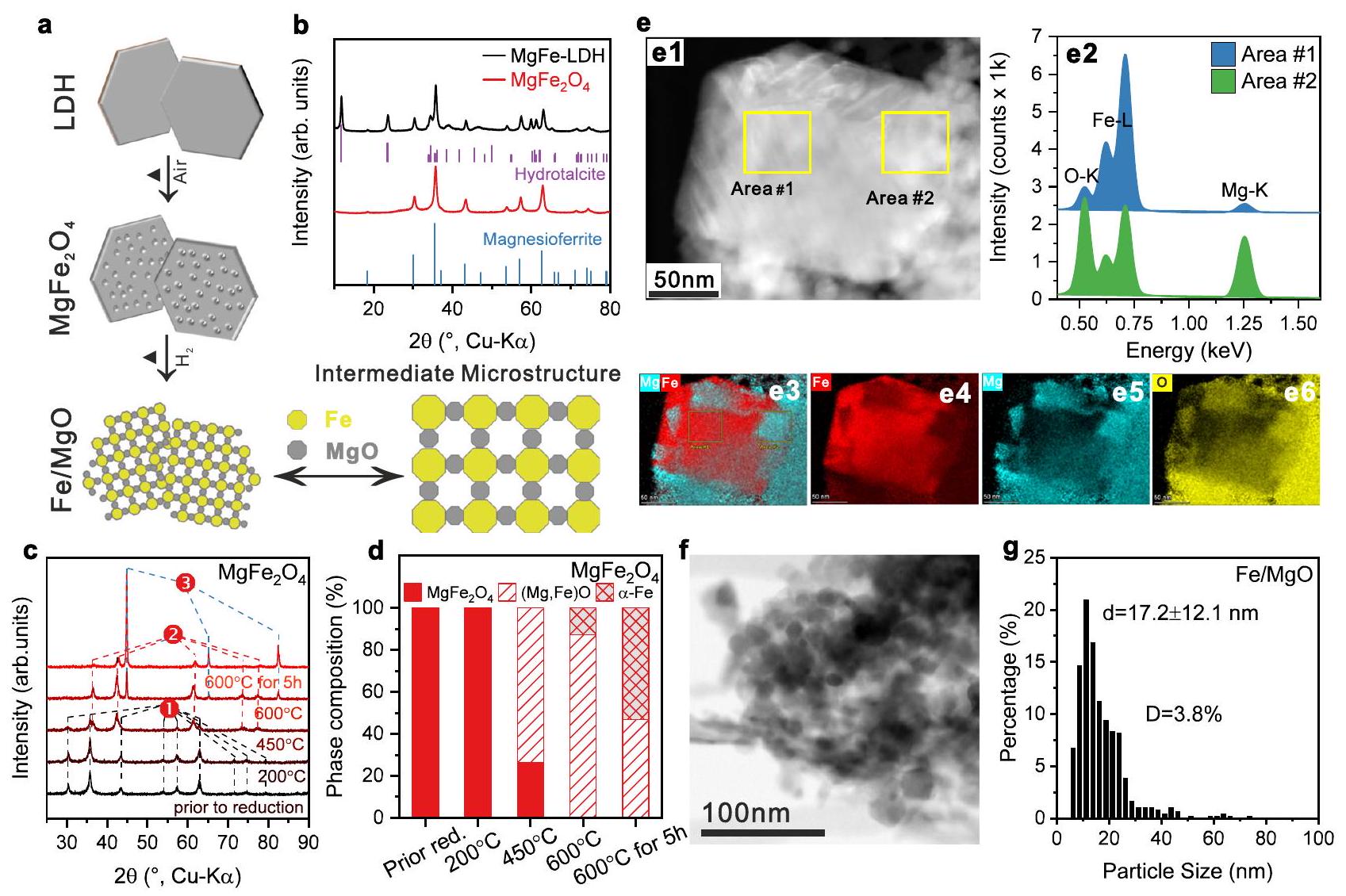
الشكل 1 | محفز الحديد عالي التحميل بواسطة نهج السبينل. أ مخطط نهج التخليق نحو بنية ميكروية وسيطة بين المحفز المدعوم والمحسن الكتلي. ب أنماط XRD لمادة LDH السابقة ومحفز مسبق من سبينل. المراجع: مغنيسيوفيريت (ICSD: 41290)، هيدروتالسايت (ICSD: 182294) (ج، د) تحليل الأشعة السينية في الموقع لعملية الاختزال والتحولات التركيبية الطورية المقابلة أثناء الاختزال بناءً على تحسين ريتفيلد لـ، في (ج) (1) هوالمرحلة، (2) هي مرحلة المغنيسيووستيت، (3) هيمرحلة. صورة HAADF-STEM التمثيلية لمحفز Fe/MgO، طيف EDS المقابل تم جمعها في المنطقة رقم 1 و 2 (e2)، ونتائج الخرائط مع المعاد بناءهاصورة التركيب (e3)تتعلق خرائط EDS بكثافات خط K منو المغنيسيوم.صورة تمثيلية لـ BF-STEM من المحفز و(ز) توزيع حجم المعدن المقابل، الذي تم تحديده من خلال تقييم ما لا يقل عن 400 جزيء. تمثل شريط الخطأ الانحراف المعياري من خلال تحليل إحصائي لحجم الجزيئات. يتم توفير بيانات المصدر كملف بيانات مصدر.
الشكل 2 | النشاط التحفيزي والخصائص الهيكلية لـمحفز نشاط تحفيزي لـلتفاعل تحليل الأمونيا:تحويل (يسار) ومعدل التكوين مع الوقت على البث (TOS) عند (يمين). أنماط XRD للعينات التي تم تقليلها حديثًاوالمُنفقالعامل المساعد بعد ظروف التفاعل دون التعرض للهواء. المراجع: (ICSD: 52258)، وُستيت المغنيسيوم (ICSD: 181215)، (ICSD: 79981). قياس XAS أثناء التشغيل لمحفز Fe/MgO: (ج) طيف XANES عند حافة Fe K، (د) تحويل فورييه-طيف EXAFS الموزون في فضاء R عند حافة الحديد K. تم رسم أطياف EXAFS في فضاء R بدون تصحيح الطور. المعادل-فضاء
تم رسم طيف EXAFS في الشكل التكميلي 13. e طيف XANES لحدود K للحديد المرجعي لحديد المعدن، و ، التي تم استرجاعها من قاعدة بيانات عينات المعايير XAFS في SPring-8 BL14B2. المعنية تم رسم طيف EXAFS في فضاء -space و R-space في الشكل التكميلية 14.المخطط الطوري المحسوب لنيترة الحديد. النقطة الزرقاء تمثل الحالة القريبة منالتوازن لتفككفيأقل من 1 بار بينما النقطة الحمراء تمثل الحالة التي تقترب منالتوازن لتفاعل و فيأقل من 200 بار. يتم توفير بيانات المصدر كملف بيانات المصدر. تشير النتائج بذلك إلى أن جزءًا كبيرًا من على الأقلمن إجمالي محتوى الحديد من الصعب تقليله ويظل فيحالة المحلول الصلب. ومع ذلك، من أجل الاختصار، سنشير إلى مرحلة الدعم باسم MgO والمحفات المخفضة باسم.
محفز الحديد عالي التحميل: الأداء التحفيزي والتوصيف
تمت دراسة التركيب الطوري للمحفز على النانو مقياس بواسطة STEM-EDS. كما هو موضح في الشكل 1 e1، جزيء كبير معزول ( ) كانت محاطة بعدد من الجسيمات الأصغر. استنادًا إلى نتائج EDS (الشكل 1 e2-e6)، تم تعيين الجسيم الكبير إلى معدن الحديد والجسيمات المحيطة الأصغر إلى مرحلة الأكسيد ( تمت دراسة البنية المجهرية لهذه المحفزات المركبة بشكل أعمق باستخدام TEM و تظهر البنية الدقيقة المتوسطة بين المحفز الضخم والمحفز المدعوم من الشكل 1f والشكل التكميلي 23a1، حيث تعرض تجمعات نموذجية من الحديد المعدني الأكبر وحبيبات الدعم الأكسيدية الأصغر. كشفت تحليل حجم جزيئات الحديد عن توزيع حجم أحادي النمط، ولكنه واسع، مع متوسط حجم جزيئات حوالي (الشكل 1g والشكل التكميلي 23a2). كما تم الإشارة سابقًا، على عكس المحفزات المدعومة التقليدية، لا تشكل جزيئات الأكسيد مادة مسامية مستمرة نموذجية، بل تتوزع بشكل فردي بين جزيئات المعدن الأكبر التي تعمل كفواصل بينها، وبالتالي تعمل بشكل يشبه المروج الهيكلي النموذجي في المحفزات الكتلية. مثل هذه “البنية الدقيقة المتوسطة” للمحفزات المعدنية الأساسية ذات التحميل العالي معروفة، على سبيل المثال، من الصناعة.محفز لتخليق الميثانول نتيجة لطريقة ترسيب مشترك مماثلة.
الشكل 3 | الخصائص الهيكلية لـ / المحفز. (أ) تحليل حي بالأشعة السينية (XRD) لعملية الاختزال و(ب) التحولات المقابلة في تركيب الطور أثناء الاختزال استنادًا إلى تحسين ريتفيلد.، في (أ) هو المرحلة، 2 هيمرحلة شبيهة بالوستيت، 3 هيمرحلة. صورة تمثيلية BF-STEM لـحجم توزيع جزيئات سبائك الحديد والكوبالت (FeCo) المحفز، والذي تم تحديده من خلال تقييم ما لا يقل عن 400 جزيء (في الإطار في (ج)). تمثل شريط الخطأ الانحراف المعياري من خلال تحليل إحصائي لحجم الجزيئات.صورة STEM و (f) الأطياف EDS المقابلة التي تم جمعها في المنطقة #1 و #2 (e) بالإضافة إلى خرائط EDX، والتي تتعلق بـ
الأداء التحفيزي لـالمحفز في الأمونيا المخففة أظهر نشاطًا مستقرًا في نطاق درجات حرارة من 400 إلى (الشكل 2أ). الكتلة الثابتة للمحفز المعدلة حسب الكتلة معدل الإنتاج فيوصلت (الشكل 2أ)، الذي تبين أنه في النطاق المعتدل إلى العالي من الأداء المبلغ عنه سابقًا لمحفزات قائمة على الحديد (الجدول التكميلي 5). تم العثور على سبب هذه النشاط النسبي المنخفض في التحليل الهيكلي للمحفز المستهلك باستخدام XRD وXES خارج الموقع وXAS أثناء التشغيل. نمط XRD للمحفز المستهلك المحفز بدون تعرضه للهواء أظهر انعكاسات واضحة لـوالمغنيسيوم الحديدي-الويستيت، مع المقارنة مع المادة المخفضة حديثًا (الشكل 2ب). علاوة على ذلك، طيف انبعاث الأشعة السينية من القشرة إلى التكافؤ (VtC XES) لعنصر الحديد المستهلك يتماشى أيضًا مع النيتريد ويؤيد تحول الحديد إلى نيتريد الحديد بعد التحفيز (الشكل التكميلي 10).
لتحقيق السبب والتحقق من التحولات الطورية القابلة للعكس المحتملة، تم استخدام مطيافية امتصاص الأشعة السينية أثناء التشغيل (XAS) تم استخدامه لدراسة الهيكل الإلكتروني والهندسي لأنواع الحديد والكوبالت في المحفزات أثناء التفاعل. الشكل 2c و d يظهر طيف امتصاص الأشعة السينية بالقرب من الحافة (XANES) وتحويلات فورييه (FTs) لطيف الامتصاص الدقيق الممتد للأشعة السينية (FT-EXAFS) الذي تم جمعه لـالمحفز تحت ظروف التفاعل عند حافة الحديد K. الـ XANES لـأظهر ميزة حادة قبل الحافة عند 7114.3 إلكترون فولت ناتجة عن انتقالات 1s إلى 3d، وموقع حافة صاعدة عند 7123.3 إلكترون فولت (تم تحديده من خلال موقع الطاقة عند نصف امتصاص الحافة في XANES المعيارية)، والذي تم نقله بمقدار -3.8 إلكترون فولت مقارنةً بورق الحديد. شكل الحافة وموقعها من المحفزات السابقة متطابقة تقريبًا مع تلك الخاصة بالسبينيل التجاريالمرجع (الشكل 2e)، الذي يحتوي على مزيج من الشكل الرباعيوثماني السطوحمنسقالمواقع في الشبكة. بعد التخفيض فيفيموضع حافة XANES المخفضةتم نقل المحفز إلى وضع قريب جدًا من وضع الحديد المعدني ويمكن ملاءمة طيف EXAFS بواسطة اثنينالمسارات المشتقة منهيكل (في و على التوالي) دون مساهمة منالتنسيق (الشكل التكميلي 16e، f والجدول التكميلي 3)، مما يشير إلى أن الحديد المعدني هو المكون الرئيسي في الكتلة. وهذا يظهر أن الاختزال يصل إلى الاكتمال بشكل أسرع في مفاعل الكوارتز الشعري المستخدم لقياس XAS مقارنة بمفاعل السرير الثابت، على الأرجح بسبب الكمية الصغيرة جداً من العينة. الانتقال إلىجو فيأدى إلى تغييرات واضحة في منطقة XANES مقارنةً بالحالة المختزلةالعامل المساعد، بما في ذلك انخفاض شدة ميزة ما قبل الحافة بين 7112 و 7118 إلكترون فولت، واختفاء قمة الكتف عند حوالي 7125 إلكترون فولت وظهور ميزة الخط الأبيض عند حوالي 7129 إلكترون فولت (الشكل 2c). في طيف EXAFS المقابل، وُجد تنسيق أقصر بكثير من ذرة تشتت خفيفة، جنبًا إلى جنب مع تحول في قشرة الحديد-حديد إلى مسافة أطول (الشكل 2d). استنادًا إلى نتائج تركيب EXAFS، فإن القشرة التنسيقية الأولى المنسوبة إلى مسار تشتت الحديد-نيتروجين/أكسجين مع عدد تنسيق (CN) منفي (الشكل التكميلي 16g و h والجدول التكميلي 3)، والذي هو أقصر من المعتاد رابطة في كلاهما و الأكاسيد، ولكن أيضًا أطول منالمسافات في فئات نيتريد الحديد المعروفة (الجدول التكميلي 4). يتم ضبط القشرة الثانية كمتناثر Fe-Fe مع عدد التنسيق (CN) منومتوسط مسافة، وهو مشابه جدًا لمسافة الحديد-حديدفي (الشكل التكميلي 16g، h، الجدول التكميلي 3-4). تشير الاختلافات الملحوظة في EXAFS إلى تغييرات هيكلية كبيرة تبدو للوهلة الأولى وكأنها تشكيل أكسيد من المرحلة المعدنية. ومع ذلك، يتم استبعاد ذلك من خلال موضع حافة XANES لـ MgO تحت شرط التحلل، الذي لا يتوافق مع التحول إلى مرحلة أكسيد، ويؤدي إلى الاستنتاج الأكثر احتمالاً بأن التغيرات في الهيكل الإلكتروني (من XANES) وفي بيئة التنسيق (من EXAFS) كانت ناتجة عن نيتريدات المرحلة المعدنية للحديد. يمكن أيضًا دعم هذه الظاهرة من خلال مقارنة أطياف XANES وEXAFS لـومراجع رقائق الحديد (الشكل 2e). في الحالة الأخيرة عندماتم تبريد المحفز من 550 إلىفي، انتقل حد الامتصاص بواسطةإلى طاقة أعلى، مع الحفاظ على معظم ميزات الحافة وقمة الكتف قبل الحافة البارزة نسبيًا (الشكل 2c). على الرغم من الفروق الكبيرة بين عوامل ديباي-والر ( ) عند 550 و ، أرقام التعريف لكل من و تم زيادة الروابط بشكل طفيف فقط (الشكل التوضيحي 16g-j، الجدول التوضيحي 3). ومع ذلك، كان هناك انخفاض ملحوظ في القشرة الأولىالمسافة إلىتم ملاحظته من نتائج تركيب EXAFS، بينما تظل مسافة الحديد-حديد في القشرة الثانية ثابتة عندالذي لا يزال مشابهًا لمسافة الحديد-حديدفي (الشكل التوضيحي الإضافي، الجدول التكميلي 3). تشير مثل هذه التحولات الهيكلية إلى تحول النيتريد المتكون فيإلى مرحلة أكثر استقرارًا في درجة حرارة الغرفة.
كانت تقنيات XAS أثناء التشغيل، وXRD خارج الموقع، وXES جميعها متوافقة مع الفرضية التي تفيد بأن حالة العمل لمحفزات الحديد الأحادية المعدن في تحلل الأمونيا، توجد مرحلة نيتريد الحديد، حتى في الأمونيا المخففة. في الواقع، توفر حسابات نظرية الكثافة (DFT) دعمًا إضافيًا لنيترة الحديد تحت ظروف تحلل الأمونيا النموذجية. الاقتراب من التوازن عند ، 1 بار) كما هو موضح في الشكل 2f والشكل التوضيحي 25. من المهم أن نلاحظ أن هذا يختلف عن تخليق الأمونيا التقليدي (على سبيل المثال 200 بار،الشكل التوضيحي التكميلي 25)، حيث تم الإبلاغ عن أن “حديد الأمونيا” غير النيتريد مستقر. وهذا يشير إلى أن كيمياء السطح، بما في ذلك المعامل الرئيسي مثل طاقة ارتباط النيتروجين، قد تكون مختلفة بالنسبة لمحفزات الحديد المستخدمة في تحليل الأمونيا مقارنة بتخليق الأمونيا. قمنا بحساب طاقة ارتباط النيتروجين لـأن تكون -0.37 إلكترون فولت بالنسبة لطور الغازوهو أقل من كل من قيمة الحديد المعدني (الذي يعتبر قويًا جدًا) والروثينيوم المعدني (الذي يعتبر مثاليًا)وبالتالي، فإن التحدي في تحلل الأمونيا القائم على الحديد هو إما زيادة طاقة ارتباط النيتروجين من نيتريد الحديد أو تقليل نيتريدته مع خفض قوة ارتباط النيتروجين من الحديد غير النيتريد في نفس الوقت.
محفز ثنائي المعدن: سبك الحديد مع الكوبالت
لقد اخترنا النهج الأخير ودرسنا سبائك الحديد مع معدن أساسي ثانٍ يظهر طاقة ربط نيتروجين أقل من الحديد والروثينيوم، وفي نفس الوقت لا يشكل النيتريدات بسهولة. لذلك، اخترنا الكوبالت واستخدمنا طريقة التخليق الموضحة أعلاه للتخليق.المحفزات المسبقة من السبينل (وصفة التركيب: الشكل التوضيحي 1، حيود الأشعة السينية: الشكل التوضيحي 2) بنسب مختلفة من الحديد إلى الكوبالت مما ينتج عنه محفزات ثنائية المعدن. و بالإضافة إلى ما تم تقديمه بالفعلتظهر خصائص XRD أن المحفزات المحتوية على الكوبالت المخفضة تتكون من مرحلة معدنية واحدة، والتي تعتمد على هو نسخة مخفيةسبائك، أو Co بتنسيق FCC، مع أكسيد يشبه الويستيتالطور، الذي لا يزال يحتوي على بعض كاتيونات المعادن الانتقالية مشابهة لـالمحفز (الشكل التوضيحي الإضافي 7).
بيانات التوصيف المقارن لـمحفزيظهر المحفز المسبق في الشكل 3. كان سلوك التنشيط في تحليل حي بالأشعة السينية (XRD) مشابهًا (الشكل 3أ، تحسينات ريتفيلد في الشكل التكميلي 9ب والجدول التكميلي 2)، ومع ذلك، وُجد أن المحفز المسبق ليس نقيًا تمامًا من حيث الطور، ولكنه احتوى على مادة شبيهة بالوستيت.قبل التخفيض بالفعل، الذي زاد محتوى الطور فيه مع التنشيط (الشكل 3ب). أظهرت تقنية المجهر الإلكتروني النافذ أنيتميز المحفز بوجود “بنية دقيقة وسيطة” مشابهة لـالعينة تتكون من جزيئات معدنية أكبر وجزيئات أكسيد أصغر (الشكل 3c). تظهر أحجام الجزيئات المعدنية توزيعًا واسعًا ووجد أنها أصغر قليلاً مما كانت عليه فيمحفز بحجم (الشكل 3c المدخل). من المهم أن قياسات STEM-EDS المحلية (الشكل 3d) وخرائط EDS (الشكل 3e، f) تُظهر أن الجسيمات المعدنية الكبيرة (المنطقة #1) تحتوي على كل من المعادن الحديد (Fe) والكوبالت (Co)، والتي تتوزع بشكل متجانس في جسيم واحد. هذا يدعم تشكيل جسيمات سبيكة ثنائية المعدن. في الوقت نفسه، تحتوي الجسيمات المحيطة (المنطقة #2) في الغالب على المغنيسيوم (Mg) والأكسجين (O) مع نسبة صغيرة من الحديد و/أو الكوبالت، مما يدعم تشكيل مادة تشبه الويستيت.خرائط EDS و XRD في الموقع لعملية التنشيطأثبتت البنية الدقيقة المتوسطة المماثلة كماالعامل المساعد (انظر المزيد من المعلومات في الشكل التوضيحي التكميلي 9a، الشكل التوضيحي التكميلي 11، والجدول التكميلي 2).
نمط حيود الأشعة السينية للمواد المستهلكةأظهر المحفز بعد تفاعل تحلل الأمونيا انعكاسات مشابهة لتلك التي تم تقليلها حديثًا، مما يشير إلى أن سبيكة الحديد والكوبالت المعدنية ظلت خلال التفاعل دون نيتريد (الشكل 3g). دراسات XAS أثناء التشغيل لـتم إجراء التفاعلات أيضًا باستخدام المحفزات تحت نفس ظروف التفاعل.ما قبل المحفز المقاس عندعرضت طيفيات XANES و EXAFS مشابهة لـالمحفز المسبق. عند التعرض لـتم تقليل المحفز تقريبًا إلى الحديد الكوبالت المعدني، حيث كانت حافة الامتصاص تقريبًا متداخلة مع تلك الخاصة بورق الحديد. تم ملاحظة تحول مشابه من نتائج XANES وEXAFS الخاصة بحافة كوبر Co K.
الشكل 4 | الأداء التحفيزي لمختلفالعوامل المساعدة وعلاقتها بالتحلل المحسوب المقابلطاقة الامتزاز. معدل التفاعل في الحالة المستقرة لـالإنتاج (أ) و TOF (ب) للمواد الحفازة الأربعة لتفكك الأمونيا عند. تم حساب زمن الطيران (TOF) لتحلل الأمونيا عند باركوظيفة للتفككطاقة الامتزاز كما هو مذكور في الأدبيات. د التجارب TOFs الأربعةالعوامل المساعدة كدالة للانفصال المقابلطاقة الامتزاز كما تم الحصول عليها من حسابات DFT. لاحظ أن نقطة الحديد النقية هي
افتراضي، كما تشير قياساتنا إلى أن هو المادة الفعالة لهذه المحفز، والمنحنى الأرجواني المتقطع موجود لتوجيه النظر. تمثل أشرطة الخطأ لمعدلات التفاعل / TOFs الانحراف المعياري من خلال قياسين متكررين، بينما تمثل أشرطة الخطأ للديسوسيات المحسوبة تمثل طاقة الامتزاز الانحراف المعياري المحسوب للاختلاف الموزون بشكل مناسب من المجموعات المقدمة في دالة BEEF-vdW.تُقدم بيانات المصدر كملف بيانات مصدر.
(الشكل التوضيحي 12). على عكس محفز Fe/MgO، لم تحدث تغييرات ملحوظة فييمكن ملاحظته إما في طيف XANES أو في طيف EXAFS خلالتفاعل التحلل عند كل من حافة الحديد K وحافة الكوبالت K مع المقارنة بالشرط تحتخفض في (الشكل 3h و i والشكل التكميلي 12)، مما يوفر دليلًا تجريبيًا على أن إدخال الكوبالت إلى المحفز يعزز بشكل كبير من استقرار المرحلة المعدنية من الحديد ضد النيتريدات الضخمة. لتعيين التثبيط الملحوظ للنيتريدات إلى تكوين السبيكة، تم إعداد خليط مادي من و تم اختباره أيضًا في تحليل الأمونيا. كانت نشاط هذه الخلطة بين نشاط النقي و (الشكل التوضيحي 22a). بعد تحلل الأمونيا، أظهر تحليل حيود الأشعة السينية (XRD) لمزيج المحفز المستهلك اختفاء الـتأملات أثناء تشكيل نيتريدات الحديد البلورية، بما في ذلك و لذلك، يمكن أن يُعزى كبح نيتريد الحديد إلى تكوين السبيكة وليس إلى وجود الكوبالت غير السبيكي بمفرده.
المحفز ثنائي المعدن: العلاقة بين النشاط وطاقة ارتباط النيتروجين
مقارنة الأداء التحفيزي لجميع الأربعةالعوامل المساعدة،أظهر المحفز أدنى تحويل للأمونيا للأسباب الموضحة أعلاه. استبدالمع Co فيأسفر عن تحسين ملحوظ في النشاط (الأشكال التكميلية 17-18). ومع ذلك، فإنأظهر المحفز مع الاستبدال الكامل للحديد تحويل أمونيا مشابهًا للمحفزات الثنائية المعدن. من أجل أخذ التوزيعات المعدنية المختلفة للمحفزين الأربعة في الاعتبار، تم قياس معدلات التفاعل لـتشكيل فيتم تقييمها ومقارنتها بعناية بين هذه المحفزات الأربعة، أولاً على أساس كتلة المحفز (الشكل 4 أ والشكل التكميلي 18). تم تطبيع كتلة المحفز في حالة الاستقرارإنتاج معدل الـتم زيادة المحفز بوضوح إلى و للعينتين المبدلتين بـ Co، و “، على التوالي. بالنسبة لـ “النقيالمحفز، انخفض المعدل قليلاً مرة أخرى إلى مما أدى إلى تطور يشبه البركان في المعدلات مع زيادة محتوى الكوبالت (الشكل 4أ). علاوة على ذلك، الحفاز حافظ على معدل تفاعل مستقر عندأكثر من 1000 دقيقة في اختبار المتانة (الشكل التوضيحي التكميلي 19). لتقييم المعدلات الجوهرية، يجب أخذ الفروقات في توزيع المعادن التي تم تقييمها بواسطة STEM في الاعتبار (الشكل التوضيحي التكميلي 23). تم حساب قيم TOF بناءً على توزيعات أحجام جزيئات المعدن مع افتراض أن أسطح الجزيئات مكشوفة بالكامل وأن جميع ذرات السطح لها نشاط متساوٍ. قد لا تكون هذه الشروط الحدودية واقعية تمامًا، ولكن يمكن اعتبار الأخطاء المنهجية متشابهة لجميع المحفزات مما يتيح مقارنة مع الحسابات النظرية بشأن الاتجاهات بين المحفزين الأربعة. تم إجراء امتصاص كيميائي إضافي مع TPD لتحديد السطح المعدني المكشوف بناءً علىسعة الامتصاص الكيميائي. بافتراض نفس النسبة المولية للمواد الممتصة لجميع المحفزات، تتبع التشتت المعدني الناتج الاتجاه، وهو مشابه للاتجاه الذي تم الحصول عليه من توزيع حجم الجسيمات بواسطة TEM: (الأشكال التكميلية 23 و 24). ومع ذلك، فإن التشتت المستمد من الكيمياء السطحية أقل بحوالي ست مرات من تلك المستمدة من توزيع حجم الجسيمات. قد تكون الأسباب هي تغطية الأكسيد التي لم تؤخذ في الاعتبار في تقييم TEM، أو الإزالة المبكرة للهيدروجين الممتص أثناء التطهير قبل TPD، و/أو عدم اليقين في نسبة المواد الممتصة. لذلك، بينما يمكن تأكيد الاتجاه النسبي العام بين المحفزات من خلال الكيمياء السطحية، سنعتمد في المناقشة التالية القيم المطلقة على التشتتات المستمدة من TEM تعتبر حدًا أدنى للقيم المقابلة لـ TOF، والتي ستكون أعلى إذا تم اشتقاقها من بيانات الامتصاص الكيميائي.
من المهم أن نلاحظ أن معدلات الدوران لهذه المحفزات الأربعة عندتظهر نفس التباين على شكل بركان مع زيادة محتوى الكوبالت مثل بيانات معدل الكتلة العادية كما هو موضح في الشكل 4ب، لكن تفوق المحفزات الثنائية المعدن أوضح بكثير. ومن المثير للاهتمام أن كلا المحفزين الثنائي المعدن و تظهر تقريبًا نفس النشاط الجوهري (TOF ) لتحلل الأمونيا. ومع ذلك، أظهر وقت طيران أصغر بكثير من، وهو ما يعادل. من هذا، نستنتج أن كميات صغيرة من الكوبالت تعزز المحفزات الحديدية الأحادية المعدن بكفاءة عالية من خلال قمع تكوين النيتريد. إن زيادة محتوى الكوبالت نحو المحفزات الأحادية المعدن من الكوبالت لا تؤدي إلى تحسين إضافي في النشاط الجوهري. إن طاقة التنشيط الظاهرة ( ) تم حسابه من مخططات أرهينيوس لهذه المحفزات الأربعة (الشكل التكميلي 20) ووجد أنه أقل قليلاً لـ و مقارنةً بالكاتاليزتين ثنائي المعدن FeCo وفقًا للاتجاه على شكل بركان. حيث أن الفرق لم يكن كبيرًا ( ومن غير المحتمل أن تكون ذات دلالة كبيرة، يمكن الافتراض أن تحلل الأمونيا يعمل عبر آلية تفاعل مشابهة لمحفزات الحديد والكوبالت أحادية أو ثنائية المعدن، بما يتماشى مع الأدبيات التي تشير إلى أن الخطوة المحددة لمعدل التفاعل هي خطوة انبعاث النيتروجين على المحفزات القائمة على الحديد والكوبالت.ومع ذلك، يمكن ربط الاتجاه الناشئ لشكل البركان في طاقة التنشيط بالفرق في طاقة ارتباط النيتروجين.كما سنظهر من خلال استخدام حسابات DFT. فيما يتعلق بالعوامل الحفازة المتشابهة جدًا و ، كما قمنا بقياس طاقة التنشيط في تيار غازي بتركيز أعلى من، مما أدى إلى حوالي أخفضمنتتفق مع طاقة ربط النيتروجين المنخفضة لـ Co (الشكل التوضيحي 21).
تمت دراسة آلية تفاعل تخليق الأمونيا باستخدام حسابات DFT.من المهم، من خلال استخدام علاقات القياس لطاقة الامتزاز للوسائطوحالات الانتقاليمكن إنشاء براكين نشطة حيث يتم رسم تردد الدوران النظري كدالة لطاقة ارتباط النيتروجين إلى خطوات أسطح المعادن الانتقالية.قام بويزن وآخرون بإنشاء بركان نشاط لتفكك الأمونيا كدالة لطاقة التفاعل للتفكك.الامتصاص وأظهر أن هذا يختلف عن ذلك الذي يتم الحصول عليه عادةً لتخليق الأمونيا حيث أن الظروف من حيث درجة الحرارة والضغوط مختلفة (الشكل 4c يظهر عملهم الأصلي فيبار، و. في عملهم، طوروا مفهوم دمج العناصر ذات الروابط القوية والضعيفة مع النيتروجين، الذي نتبعه في هذا العمل. اقترحوا استخدام CoMo كتركيبة ثنائية معدنية جذابة لتفكيك الأمونيا، وهم وآخرونوجد تجريبيًا أنتم تشكيل النيتريد في الكتلة وهو الطور النشط، وهو ما لا ينطبق على محفزات FeCo في هذا العمل، التي تظل غير نيتريدية.
استخدمنا نظرية الوظائف الكثيفة (DFT) لحساب طاقات ارتباط النيتروجين على أسطح المحفزات الأربعة المستخدمة هنا وفسرناها في ضوء البركان الذي أنشأه بويزن وآخرون. باستخدام منهجيتنا، حصلنا على طاقات ارتباط النيتروجين التي تختلف قليلاً فقط عن تلك المبلغ عنها في العمل الأصلي (لـحسبنا -0.16 إلكترون فولت مقارنة بـيظهر بركان النشاط باستخدام أوقات التحويل التي تم الحصول عليها تجريبيًا (المعدلة حسب مساحة سطح المعدن) كدالة لطاقة ارتباط النيتروجين المحسوبة لأسطح مختلفة من الحديد والحديد-الكوبالت في الشكل 4د، باستخدام نفس المحور السيني كما في 4ج. كما يتضح من الشكل 4د، تشير بياناتنا إلى سلوك من نوع البركان مشابه لما توقعه بويزن وآخرون. لاحظ أن البيانات لـ (الرابطة القوية في الجانب الأيسر من البركان) هي فقط فرضية تحت ظروف تحلل الأمونيا، تم نيتريد المحفزات لتشكيل الكتلة المستقرةكما اقترحته تقنيات XAS أثناء التشغيل، وXRD خارج الموقع، وXES (الشكل 2b-d والشكل التكميلي 10). هذا ينقل طاقة ارتباط النيتروجين إلى جانب الارتباط الضعيف ويشرح النشاط المنخفض الذي لوحظ لحديدنا. العامل المساعد. إذا كان بالإمكان تجنب النيتريدation،يجب أن تظهر نشاطًا أعلى كما يتضح من الشكل 4c، d.لديه أيضًا طاقة ربط نيتروجين ضعيفة إلى حد ما، وبالتالي فهو محفز ضعيف لكل من تخليق الأمونيا وتحللها. ومع ذلك، فإن سبك الحديد مع الكوبالت يؤدي إلى أسطح تتمتع بطاقات ربط نيتروجين قريبة من قمة بركان تحلل الأمونيا النظري. هذه هي أيضًا نتيجة جهودنا التجريبية التي تظهر أن سبائك FeCo لديها نشاط أعلى من كلاهما،وشركة. تأثير سبك الحديد مع الكوبالت هو بالتالي مزدوج، (1) كبح النيتريدات و (2) إضعاف طاقة ارتباط النيتروجين.
باختصار، وجدنا أن المحفزات الثنائية المعدن من سبائك الحديد والكوبالت ذات التحميل العالي مع “البنية الدقيقة المتوسطة” بين المحفزات المدعومة والمحفزات الكتلية التي تم تصنيعها بواسطة نهجنا في السبينل من خلال الترسيب المشترك يمكن أن تطلق بكفاءةمنالتحلل. كشفت التوصيفات المتعمقة والمكملة عن نيتريد الحديد من السطح إلى الكتلة تحت تحلل الأمونيا، وهو ما يختلف عن تخليق الأمونيا. قدمت حسابات DFT أدلة إضافية على نيتريد الحديد وكشفت أنتظهر الأسطح طاقات ارتباط ضعيفة جدًا وبالتالي تكون أقل نشاطًا. من خلال سبك الحديد مع الكوبالت، يمكن تقليل هذه النيتريدية ويتأثر طاقة ارتباط النيتروجين بشكل إضافي بحيث تقترب طاقات الارتباط من قمة بركان النشاط، مما يؤدي إلى أداء تحفيزي نشط ومستقر للغاية. تشير هذه الدراسة أيضًا إلى أن سبك الحديد مع معادن أخرى ذات طاقة امتصاص نيتروجين ضعيفة يوفر نهجًا بسيطًا وعامًا لتصنيع محفز عالي النشاط وغير نيتريدي لتفاعل تحلل الأمونيا.
طرق
المواد
لتحضير سلف الكاتاليسا، تم استخدام المواد الكيميائية المتاحة تجارياً دون مزيد من التنقية: نترات الكوبالت (II) سداسية الماءكبريتات الحديد (II) هيدرات سباعيةنترات الحديد (III) غير المائي ( نترات المغنيسيوم سداسي الهيدرات (، ACS، ألفا أيسر GmbH)، كربونات الصوديوم (p.a.، أبلي كيم GmbH) وهيدروكسيد الصوديوم (VWR International BVBA.
تحضير المحفز
تم تحضير المحفزات من السبينل عن طريق الترسيب المشترك للـ LDHs/الهيدروكسيد في نظام مفاعل مختبري آلي (محطة تخليق Optimax، ميتلر توليدو). خلال عملية الترسيب المشترك، احتوى محلول المعدن على ثلاثة تركيزات متساوية من ( ) من حيث نسبةيحدد النسبةفيالمائي و تعمل المحلول كعامل ترسيب. يكون الرقم الهيدروجيني أثناء الترسيب المشترك 10.0 لـ بالإضافة إلى وهو 10.5 لـمع وقت شيخوخة يبلغ 24 ساعة عند. لحل لـ و حل لـنسبة هو تعمل المحلول كعامل ترسيب. يكون الرقم الهيدروجيني أثناء الترسيب المشترك 11.0 مع وقت شيخوخة قدره 1 ساعة عند.
بعد الغسل بالماء حتى أصبحت موصلية السائل العلوي أقل من، ثم بعد التجفيف، تم تسخين المواد السابقة عندلمدة 3 ساعات ثم تم تقليلها حرارياً فيقبل التفاعل.
توصيف المحفز
تم تحديد محتويات الحديد والكوبالت والمغنيسيوم في عينات السبينل بواسطة مطيافية الامتصاص الذري (AAS) (شركة ثيرمو إلكترون، سلسلة M). تم تحديد محتويات الصوديوم في العينات بواسطة مطيافية الانبعاث الضوئي البلازمي المقترن بالحث (ICP-OES) (أفيو 200 من بيركين إلمر). تم إجراء قياسات الوزن الحراري (TG) في محلل حراري NETZSCH STA 449F3. في وعاء من الكورندوم، تم استخدام حوالي 50 ملغ من LDH / هيدروكسيد. تم تسخين المواد السابقة في هواء صناعي (في العربيةإلىمع معدل تسخين خطي قدرهتم إجراء تجارب الامتزاز وإزالة الامتزاز لمواد LDH والسبينيل باستخدام جهاز NOVA3000e (أدوات كوانتاكروم) فيبعد إزالة الغازات من العينات فيلمدة ساعتين في الفراغ. تم حساب مساحات السطح باستخدام طريقة BET (بروناور إيميت تيلر) من البيانات بين 0.05 و 0.3. تم تحديد أحجام المسام وتوزيع أحجام المسام من خلال تطبيق طريقة BJH (بارت-جويتر-هاليندا). تم تسجيل أنماط حيود الأشعة السينية البودرة (XRD) لمراحل LDH وسبينل على جهاز حيود Bruker D8 Advance في هندسة Bragg-Brentano باستخدام كاشف حساس للموقع LYNXEYE (مفلتر نيكل CuK الإشعاع). أ يتراوح بينإلىزمن العد 2.96 ثانية وعرض خطوةتم تطبيقه. تم توزيع العينات باستخدام الإيثانول على قرص زجاجي تم إدخاله في حامل دائري من PMMA، والذي تم تعريضه لدوران لطيف أثناء المسح. تم تسجيل أنماط حيود الأشعة السينية للمواد المحفزة المخفضة على جهاز حيود الأشعة السينية STOE STADI P في هندسة ديباي-شيرر عند درجة حرارة الغرفة باستخدام كاشف حساس للموقع ذو لوحة صورة منحنية.مو كمرشح أحادي البلورة الإشعاع). أ نطاق منوعرض خطوةتم تطبيقه. تم نقل العينات من المفاعل إلى صندوق قفاز تحت الأرجون، ثم تم دقها وملؤها في حامل عينات شعري (0.2 مم Ø). بعد ختم الشعري بشحم فراغ، تم إخراج حامل العينات من صندوق القفاز وتم ختم الفتحة المسدودة للشعري عن طريق الذوبان لمنع تلوث العينة بالهواء. تم إجراء دراسات مجهر المسح الإلكتروني البيئي (SEM) على المحفزات المسبقة من سبينل باستخدام مجهر Quanta ESEM 400 FEG، المجهز بكاشف FEI ومجهر Apreo S LoVac (Thermo Fisher Scientific) الذي يحتوي على كاشفين للإلكترونات المرتدة. تم طلاء جميع العينات بالسطح بـقبل القياسات. الحديد K غير الرنينيتم جمع بيانات طيف انبعاث الأشعة السينية (XES) في خط الشعاع ID26 من منشأة الإشعاع السنكروتروني الأوروبية (ESRF)، التي تعمل عند 6 جيجا فولت مع تيار حلقي قدره 200 مللي أمبير. تم استخدام مقياس الطيف الثنائي البلورات Si(111) في الأعلى لاختيار الطاقة وتم معايرته على نقطة الانعطاف الأولى لرقاقة الحديد المحددة عند 7111.2 إلكترون فولت. تم ضبط طاقة الشعاع الساقط على 7800.0 إلكترون فولت (فوق حافة K للحديد عند 7112 إلكترون فولت) لتحفيز العينة بشكل غير رنيني. كان حجم الشعاع عند العينة هووكان تدفق الفوتونات (دون تخفيض). تم جمع طيف XES غير الرنيني باستخدام مطياف يوهان بقطر 1 متر مزود بخمسة محللات بلورية Ge(620) وكاشف ثنائي ضوئي متزايد (APD) مصفوف على دوائر رولاند المتقاطعة. تم معايرة المطياف داخليًا باستخدام خط انبعاث لـعند 7060.6 إلكترون فولت. تم تخفيف جميع العينات في نيتريد البورون (BN) وتم قياسها في جهاز تبريد الهيليوم السائل الذي يعمل عند 20 كلفن. تم جمع جميع طيفيات XES بين 7020.0 إلكترون فولت و 7130.0 إلكترون فولت مع حجم خطوة موحد قدره 0.25 إلكترون فولت وتم تطبيعها إلى مساحة وحدة قدرها 1 علىالخطوط الرئيسية في المنطقة بين 7020.0 إلكترون فولت إلى 7080.0 إلكترون فولت.-الاختزال المبرمج بالحرارة (تم إجراء تجارب (TPR) في محلل المحفزات BELCAT-B (BEL Japan, Inc.) بمعدل تسخين خطي منبين درجة حرارة الغرفة و. تم الاحتفاظ بهذه الدرجة الحرارة لمدة 15 دقيقة قبل التبريد. تم تجفيف جميع العينات عند لمدة 60 دقيقة فيقبل التجارب. لإزالةمن تيار الغاز، تم استخدام منخل جزيئي متصل قبل الوصول إلى كاشف الموصلية الحرارية المدمج. معدل التدفق هو و فيتم استخدام (Air Liquide) لعملية التخفيض. لجميع التجارب مع محلل هذا المحفز،من العينة مع كسر منخلتم إعداد تحليل كمي لـتم تحقيق الاستهلاك من خلال دمج إشارة TCD التي تم الحصول عليها من تقليل ثلاثة كميات مختلفة من CuO التجاري للمعايرة. تم استخدامه لأن CuO يخضع لعملية اختزال كاملة إلى. -إزالة مبرمجة بالحرارة (تجارب (TPD) للحصول على معلومات عن تشتت المعادن كانت تمت في جهاز BELCAT-II (شركة BEL Japan، Inc.) بمعدل تسخين خطيبين و تم تقليل جميع العينات (حوالي 20 ملغ لكل عينة) بطريقة متساوية الحرارة في لمدة 5 ساعات في ( ، إير ليكيد) قبل التجارب، وتم تطهيره بالآرغون أثناء التبريد إلى. تم تحويل الأجواء مرة أخرى من Ar إلى فيثم تم تبريد العينة إلىوتم الاحتفاظ بهللاحتجاز عندلمدة ساعة واحدة. بعد ذلك، تم تطهير العينة بواسطة الأرجون عندلمدة ساعتين لإزالةفي الطور الغازي وممتص فيزيائيًا. ثم، تم تسخين العينات في إلى وتركيز تمت مراقبة العادم بواسطة مطياف الكتلة (QMG 220، Pfeiffer Vacuum GmbH). تم استخدام بيانات الكيمياء السطحية لحساب قيم تشتت المعدن مع افتراض نسبة ستوكيومترية منالحديد و / أو الكوبالت من 2.
قياسات XRD في الموقع
تم جمع البيانات على جهاز قياس حيود الأشعة السينية STOE theta/theta (نحاسالإشعاع، مقياس الطيف الجرافيتي الثانوي، عداد الوميض) مزود بغرفة تفاعل في الموقع Anton Paar XRK 900. تم خلط تغذية الغاز بواسطة وحدات التحكم في تدفق الكتلة من برونكهورست، باستخدامفي الهيليوم بمعدل تدفق إجمالي قدره. نظرًا لانخفاض دقة الوقت (حوالي 10 ساعات لكل مسح)، تم إجراء جميع قياسات XRD عند لتجنب الانخفاض المستمر في العينة أثناء جمع البيانات (“شبه في الموقع”). تم تقليل العينات في غرفة في الموقع بمعدل انحدارحتى تم الوصول إلى درجة الحرارة المستهدفة المعنية، تلاها تبريد سريع ( ) وقياس XRD عند . بعد ذلك، تم تسخين العينة مرة أخرى عند حتى درجة الحرارة المستهدفة السابقة، حيث تم تغيير معدل الزيادة إلىمرة أخرى حتى تم الوصول إلى درجة الحرارة المستهدفة التالية، تليها مرة أخرى عملية التبريد السريع وقياس حيود الأشعة السينية.
قياسات STEM-EDS-map
تم إنتاج صور المجهر الإلكتروني الماسح STEM-EDS لمحفزات السبينل والمحفات المخفضة حديثًا، باستخدام جهاز Thermo Scientific Talos F200X. كان المجهر الإلكتروني الناقل مزودًا بمسدس انبعاث ميداني عالي السطوع (X-FEG) و4 كواشف EDX SDD، مما يوفر معًا منطقة كشف تبلغ 0.9 sr. كانت طاقة شعاع الإلكترون 200 keV والتيار الشعاعي 50 pA. كانت دقة النقطة للمجهر هيÅ. من أجل تقليل العيوب الناتجة عن شعاع الإلكترون على العينة، تم تطبيق نهج الإطارات المتعددة. وهذا يعني أنه تم مسح شعاع الإلكترون عبر منطقة الاهتمام عدة مرات، مع أوقات اكتساب قصيرة تتراوح من 20 إلىلكل بكسل، وتم دمج الإشارة لاحقًا. لتعويض انحراف العينة أثناء اكتساب EDS، تم تطبيق تصحيح انحراف Velox بواسطة الارتباط المتقاطع بعد كل إطار. تم تحديد توزيع حجم الجسيمات أحادية المعدن / ثنائية المعدن من خلال تقييم ما لا يقل عن 400 جسيم.
تشتت جزيئات النانو أحادية / ثنائية المعدن: حساب من نتائج STEM
مع القطر المعروف ( ) من جزيئات المعادن النانوية الفردية ( )، كما تم قياسه بواسطة STEM، متوسط قطر الحجم-المساحة ( ) تم حسابها وفقًا للمعادلة (1). من هذه العلاقة، يمكن للمرء بسهولة حساب تشتت المعدن ( )، والذي يتم تعريفه بنسبة ذرات السطح إلى العدد الإجمالي للذرات في الجسيم المعدني نصف الكروي ( حجم ذرة المعدنمساحة السطح لذرة المعدن) كما هو موضح في المعادلة (2).
القياسات الحركية
قبل قياسات الحالة الثابتة الحفزية، 20 ملغ من المحفزات السبينيلية (تم تقليلها عند درجة حرارة ثابتة لمدة 5 ساعات فياير ليكيد، ). بعد ذلك، تم تبريد العينات التي تم تقليلها حديثًا إلى وتم نيتريدته لمدة 5 ساعات في خليط منفي هواير ليكيد. تم إضافة خطوة النيتريدation في البداية لـمحفز للحصول على نشاط تحفيزي مستقر وأخيرًا تم استخدامه للجميعالعوامل المساعدة للحفاظ على القابلية للمقارنة. ثم تم إجراء قياسات تفكك الأمونيا الحفازة في حالة الاستقرار بين 400 و. أولاً، تم تبريد العينات إلىبمعدل تدفق غاز قدرهالذي تم توجيهه عبر سرير الحفاز. بعد القياس عند, تم تسخين العينات تدريجياً إلى 425،450،والاحتفاظ بها عند كل درجة حرارة لمدة 3 ساعات. تم معايرة مطياف الكتلة (QMG220، Pfeiffer Vacuum GmbH) لـ,,ومع اعتبار الهيليوم كمعيار داخلي لإجراء تحليل كمي أثناء التحفيز. تم معايرة Micro GC Fusion من Inficon لـولإجراء التحليل. تم تجاهل التغيرات في عدد المولات والحجم المقابل لمزيج الغاز بسبب التفاعل وتأثيره على بيانات التحويل حيث أنه محدود فقط بـفي تغذية الغاز وتظل نسبة الهيليوم المخفف. التحويلاتلكل العوامل الحفازة عند(89-95%) تقترب، لكنها تبقى دون تحويل التوازن(). تم حساب معدلات إنتاجالمعدلة بالكتلة والطاقة التنشيطية الظاهرة () عند تحويل منخفض
تقترب من ظروف التفاعل التفاضلي. تؤكد حسابات معيار ويز-براتر ومعيار ميارس غياب قيود نقل الكتلة لهذا النظام الحفاز كما هو موضح في المعلومات التكميلية.
تم إجراء قياسات XASتمت القياسات في الجزء CAT من خط شعاع CAT-ACT في مصدر الضوء KIT في كارلسروه، ألمانيا. عادةً ما تم تخفيف العينات باستخدام نيتريد البورون، وضغطها إلى كريات، وسحقها وتمريرها عبر منخل بين 100 و. للقياسات، تم تحميل العينات في شعيرة كوارتز (1.5 مم قطر خارجي، 0.02 مم سمك الجدار،طول السرير) وتم تركيبها فوق مروحة هواء ساخن. كان معدل تدفق الغاز عبر الشعيرة هو، وتم مراقبة تركيبة الغاز الخارجة بواسطة مطياف الكتلة Pfeiffer Vacuum OmniStar GSD 320 (مثال على التحليل عبر الإنترنت في الشكل التكميلية 15). تم جمع طيف امتصاص الأشعة السينية بالقرب من حافة الهيكل (XANES) وطيف الامتصاص الممتد للأشعة السينية (EXAFS) عند حافة Fe K (7112 eV) (لكل منوالتحفيزات السابقة) وحافة Co K(فقط للتحفيز السابق لـ)، في وضع النقل مع غرف أيونية ككاشفات. تم إجراء التجارب التالية على هذه العينة بعد التحميل الأولي: الاختزال بواسطةفي الهيليوم من(مع معدل تسارع) والإقامة لمدة 8 ساعات، ثم التبريد إلىوالتعرض لـ، ثم التسارع إلىتحتوالإقامة لمدة ساعتين، ثم التبريد إلىتحت بيئة. تم جمع طيف XANES ونطاق طاقة موسع لطيف EXAFS في نهاية تلك المرحلة. تم تطبيع البيانات المجمعة باستخدام كود أثينا ضمن حزمة ديمتر (الإصدار 0.9.26). تم الحصول على جزء EXAFS من الطيف عن طريق تحويل البيانات المعيارية من فضاء الطاقة إلى فضاءووزنها بواسطةو
، ثم تم تحويلها فورييه في نطاق k المحدد (اعتمادًا على جودة البيانات) باستخدام نافذة هانينغ. ثم تم إجراء ملاءمة البيانات في فضاء R باستخدام برنامج Artemis من نفس الحزمة مع نماذج هيكلية مختارة لجميع مجموعات البيانات الموزونة k.
حسابات DFTتم إجراء حسابات DFT في هذا العمل باستخدام حزمة محاكاة فيينا Ab Initio (VASP)بالارتباط مع بيئة المحاكاة الذرية (ASE) . تم استخدام مجموعة أساس الموجة المسطحة مع قطع
طاقة قدرها 450 eV، وطريقة الموجة المعززة بالمشاريع (PAW)ووظيفة تقدير الخطأ بايزي مع ارتباطات فان دير فالس (BEEF-vdW)تم استخدام وظيفة الارتباط. تم تحسين ثوابت الشبكة باستخدام قطع طاقة قدره 450 eV و(لـوFeCo)،(لـ
) أخذ عينات نقاط k من Monkhorst Pack. تم إعطاء ثوابت الشبكة المحسنة في الجدول التكميلية 6.كان قطع الطاقة الحركية لجميع حسابات الشرائح 450 eV. تم نمذجة أنظمةوبشرائح لانهائية تتكون من أربع طبقات سميكةخلايا كبيرةوحدة، مع إزالة صف واحد من ذرات Co في اتجاه y من الطبقة العليا لإنشاء حواف A وB. تم نمذجة نيتريد الحديد باستخدام سطح سميك من أربع طبقات مع 6 ذرات Fe و2 ذرات N في كل طبقة. تم فصل جميع نماذج الشرائح بمقدارÅ. في جميع الحسابات، تم تثبيت الطبقتين السفليتين في مواضع الكتلة بينما تم السماح للطبقتين العلويتين بالاسترخاء أثناء تحسين الهندسة. كانت معايير التقارب لتحسين الهندسة هي قوة قصوى قدرهاÅ(لـ,,,) و(لـ) لأغراض. تم اعتبار استقطاب الدوران في الحسابات. تم حساب طاقات الامتصاص للنيتروجين بالنسبة لغاز المرحلة. تم حساب تصحيحات الطاقة الصفرية من التحليلات الاهتزازية التي أجريت في التقريب التوافقي باستخدام فرق محدود بمقدارللإزاحات. تم إعطاء إحداثيات جميع الهياكل في المعلومات التكميلية.
توفر البيانات
البيانات التي تم إنشاؤها في هذه الدراسة متاحة في ملف المعلومات التكميلية/بيانات المصدر. يتم توفير بيانات المصدر مع هذه الورقة.
References
Erisman, J. W., Sutton, M. A., Galloway, J., Klimont, Z. & Winiwarter, W. How a century of ammonia synthesis changed the world. Nat. Geo. 1, 636-639 (2008).
Schüth, F., Palkovits, R., Schlögl, R. & Su, D. S. Ammonia as a possible element in an energy infrastructure: catalysts for ammonia decomposition. Energy Environ. Sci. 5, 6278-6289 (2012).
Tamaru, K. A “new” general mechanism of ammonia synthesis and decomposition on transition metals. Acc. Chem. Res. 21, 88-94 (1988).
Schlogl, R. Ammonia synthesis. in Handbook of Heterogeneous Catalysis 2nd edn, Vol. 3 (eds Ertl, G., Knotzinger, H., Schuth, F. & Weitkamp, J.) Ch. 2501-2575 (Wiley-VCH Weinheim, 2008).
Yin, S. F., Xu, B. Q., Wang, S. J., Ng, C. F. & Au, C. T. Magnesia-carbon nanotubes (MgO-CNTs) nanocomposite: Novel support of Ru catalyst for the generation of -free hydrogen from ammonia. Catal. Lett. 96, 113-116 (2004).
Chang, F., Gao, W., Guo, J. & Chen, P. Emerging materials and methods toward ammonia-based energy storage and conversion. Adv. Mater. 55, 2005721 (2021).
Chen, C. et al. Ru-based catalysts for ammonia decomposition: a mini-review. Energy Fuels 35, 11693-11706 (2021).
Yin, S.-F. et al. Investigation on the catalysis of -free hydrogen generation from ammonia. J. Catal. 224, 384-396 (2004).
Bell, T. E. & Torrente-Murciano, L. production via ammonia decomposition using non-noble metal catalysts: a review. Top. Catal. 59, 1438-1457 (2016).
Kiełbasa, K., Pelka, R. & Arabczyk, W. Studies of the kinetics of ammonia decomposition on promoted nanocrystalline iron using gas phases of different nitriding degree. J. Phys. Chem. A 114, 4531-4534 (2010).
Tseng, J.-C. et al. Tracking the active catalyst for iron-based ammonia decomposition by in situ synchrotron diffraction studies. Chem. Cat. Chem. 10, 4465-4472 (2018).
Lu, A.-H. et al. Spatially and size selective synthesis of Fe-based nanoparticles on ordered mesoporous supports as highly active and stable catalysts for ammonia decomposition. J. Am. Chem. Soc. 132, 14152-14162 (2010).
Ji, J. et al. Towards an efficient catalyst using metal amine metallate as an active phase precursor: Enhanced hydrogen production by ammonia decomposition. Int. J. Hydrog. Energy 39, 12490-12498 (2014).
Zaman, S. F. et al. Ammonia decomposition over citric acid chelated and catalysts. Int. J. Hydrog. Energy 43, 17252-17258 (2018).
Kirste, K. G. et al. Cox-free hydrogen production from ammonia mimicking the activity of Ru catalysts with unsupported Co -Re alloys. Appl. Catal. B Environ. 280, 119405 (2021).
Ortega, K. F. et al. Ammonia decomposition and synthesis over multinary magnesioferrites: promotional effect of Ga on Fe catalysts for the decomposition reaction. Chem. Cat. Chem. 9, 659-671 (2017).
Rein, D., Friedel Ortega, K., Weidenthaler, C., Bill, E. & Behrens, M. The roles of Co-precipitation ph, phase-purity and alloy formation for the ammonia decomposition activity of Ga-promoted catalysts. Appl Catal. A Gen. 548, 52-61 (2017).
Lorenzut, B., Montini, T., Bevilacqua, M. & Fornasiero, P. FeMobased catalysts for production by decomposition. Appl. Catal. B Environ. 125, 409-417 (2012).
Zhang, J. et al. Individual alloy nanoparticles on carbon nanotubes: structural and catalytic properties. Nano Lett. 8, 2738-2743 (2008).
Simonsen, S. B., Chakraborty, D., Chorkendorff, I. & Dahl, S. Alloyed Ni-Fe nanoparticles as catalysts for decomposition. Appl. Catal. A Gen. 447-448, 22-31 (2012).
Kowalczyk, Z., Sentek, J., Jodzis, S., Muhler, M. & Hinrichsen, O. Effect of potassium on the kinetics of ammonia synthesis and decomposition over fused iron catalyst at atmospheric pressure. J. Catal. 169, 407-414 (1997).
Jedynak, A., Kowalczyk, Z., Szmigiel, D., Raróg, W. & Zieliński, J. Ammonia decomposition over the carbon-based iron catalyst promoted with potassium. Appl. Catal. A Gen. 237, 223-226 (2002).
Ganley, J. C., Thomas, F. S., Seebauer, E. G. & Masel, R. I. A priori catalytic activity correlations: the difficult case of hydrogen production from ammonia. Catal. Lett. 96, 117-122 (2004).
Dahl, S., Logadottir, A., Jacobsen, C. J. H. & Nørskov, J. K. Electronic factors in catalysis: the volcano curve and the effect of promotion in catalytic ammonia synthesis. Appl. Catal. A Gen. 222, 19-29 (2001).
Boisen, A., Dahl, S., Nørskov, J. K. & Christensen, C. H. Why the optimal ammonia synthesis catalyst is not the optimal ammonia decomposition catalyst. J. Catal. 230, 309-312 (2005).
Schlögl, R. Catalytic synthesis of ammonia-a “never-ending story”? Angew. Chem. Int. Ed. 42, 2004-2008 (2003).
Kandemir, T., Schuster, M. E., Senyshyn, A., Behrens, M. & Schlögl, R. The haber-bosch process revisited: on the real structure and stability of “ammonia iron” under working conditions. Angew. Chem. Int. Ed. 52, 12723-12726 (2013).
Su, Q. et al. Layered double hydroxides derived nix(mgyalzon) catalysts: enhanced ammonia decomposition by hydrogen spillover effect. Appl. Catal. B Environ. 201, 451-460 (2017).
Ge, X., Li, M. & Shen, J. The reduction of and complex oxides studied by temperature-programmed reduction combined with in situ mössbauer spectroscopy. J. Solid State Chem. 161, 38-44 (2001).
Behrens, M. Meso- and nano-structuring of industrial catalysts. J. Catal. 267, 24-29 (2009).
Behrens, M. et al. The active site of methanol synthesis over industrial catalysts. Science 336, 893-897 (2012).
Lancaster, K. M. et al. X-ray emission spectroscopy evidences a central carbon in the nitrogenase iron-molybdenum cofactor. Science 334, 974-977 (2011).
Pollock, C. J. & DeBeer, S. Insights into the geometric and electronic structure of transition metal centers from valence-to-core x-ray emission spectroscopy. Acc. Chem. Res. 48, 2967-2975 (2015).
Westre, T. E. et al. A multiplet analysis of fe k-edge 1s pre-edge features of iron complexes. J. Am. Chem. Soc. 119, 6297-6314 (1997).
Vojvodic, A. et al. Exploring the limits: a low-pressure, lowtemperature haber-bosch process. Chem. Phys. Lett. 598, 108-112 (2014).
Abild-Pedersen, F. et al. Scaling properties of adsorption energies for hydrogen-containing molecules on transition-metal surfaces. Phys. Rev. Lett. 99, 016105 (2007).
Logadottir, A. et al. The bronsted-evans-polanyi relation and the volcano plot for ammonia synthesis over transition metal catalysts. J. Catal. 197, 229-231 (2001).
Medford, A. J. et al. Assessing the reliability of calculated catalytic ammonia synthesis rates. Science 345, 197-200 (2014).
Duan, X. et al. Understanding co-mo catalyzed ammonia decomposition: Influence of calcination atmosphere and identification of active phase. Chem. Cat. Chem. 8, 938-945 (2016).
Zimina, A. et al. Cat-act-a new highly versatile X-ray spectroscopy beamline for catalysis and radionuclide science at the kit synchrotron light facility anka. Rev. Sci. Instru. 88, 113113 (2017).
Grunwaldt, J.-D., Vegten, N. V. & Baiker, A. Insight into the structure of supported palladium catalysts during the total oxidation of methane. Chem. Commun. 28, 4635-4637 (2007).
Ravel, B. & Newville, M. Athena, Artemis, Hephaestus: data analysis for x-ray absorption spectroscopy using IFEFFIT. J. Synchrotr. Radiat. 12, 537-541 (2005).
Kresse, G. & Furthmüller, J. Efficient iterative schemes for ab initio total-energy calculations using a plane-wave basis set. Phys. Rev. B 54, 11169-11186 (1996).
Kresse, G. & Furthmüller, J. Efficiency of ab-initio total energy calculations for metals and semiconductors using a plane-wave basis set. Comput. Mater. Sci. 6, 15-50 (1996).
Bahn, S. R. & Jacobsen, K. W. An object-oriented scripting interface to a legacy electronic structure code. Comput. Sci. Eng. 4, 56-66 (2002).
Blöchl, P. E. Projector augmented-wave method. Phys. Rev. B 50, 17953-17979 (1994).
Kresse, G. & Joubert, D. From ultrasoft pseudopotentials to the projector augmented-wave method. Phys. Rev. B 59, 1758-1775 (1999).
Wellendorff, J. et al. Density functionals for surface science: exchange-correlation model development with bayesian error estimation. Phys. Rev. B 85, 235149 (2012).
Monkhorst, H. J. & Pack, J. D. Special points for Brillouin-zone integrations. Phys. Rev. B 13, 5188-5192 (1976).
Mortensen, J. J. et al. Bayesian error estimation in density-functional theory. Phys. Rev. Lett. 95, 216401 (2005).
الشكر
يود S.C. وM.B. وL.K. وS.D. أن يشكروا وزارة التعليم والبحث الفيدرالية في ألمانيا (Bundesministerium für Bildung und Forschung، BMBF، مشروع علم الهيدروجين: TransHyDE Forschungsverbund AmmoRef، FKZ 03HY203E وFKZ 03HY203A) على التمويل. يشكر L.K. وA.W. وS.D. جمعية ماكس بلانك على التمويل. يقر L.K. بمؤسسة ألكسندر فون هومبولت للحصول على زمالة ما بعد الدكتوراه ودعم التمويل. نشكر معهد فيزياء الشعاع والتكنولوجيا (IBPT) على تشغيل حلقة التخزين، ومسرع أبحاث كارلسروه (KARA) ونشكر مصدر الضوء KIT على توفير الأدوات في خط شعاع CAT-ACT من
معهد أبحاث وتكنولوجيا التحفيز (IKFT). نشكر الدكتورة آنا زيمينا والدكتور تيم برومان على مساعدتهما خلال قياسات XAS التشغيلية. تم إجراء تجارب XES على خط الشعاع ID26 في منشأة الإشعاع السنكروتروني الأوروبية (ESRF)، غرونوبل، فرنسا. نحن ممتنون للدكتور بيتر غلاتزل في ESRF لتقديم المساعدة في استخدام خط الشعاع ID26.
مساهمات المؤلفين
أجرى S.C. وD.R. تخليق المواد، والتوصيفات الأساسية، واختبارات الأداء التحفيزي وتحليل البيانات. قام J.J. وF.S. بإجراء حسابات DFT وتفسيرها. قام F.-P.S. بإجراء قياسات STEM-EDS-map. قام S.C. بإجراء تقييم تشتت المعدن وتجربة امتصاص H2. قام F.G. بإجراء قياسات XRD في الموقع وتحليل البيانات. قام S.N. وD.R. وK.F.O. بإجراء تجارب XAS بمساعدة D.E.D. قام L.K. وS.D. بإجراء تحليل بيانات XAS. ساهم S.C. وS.N. وD.E.D. وJ.-D.G. وM.B. في المناقشة وتفسير بيانات XAS. قام L.K. وA.W. وS.D. بإجراء تجارب XES وتحليل البيانات. قام A.R. بتخليق وتوصيفالحفاز. قام J.W. بإجراء قياسات XRD إضافية للمراجعة. ساهم T.L. وR.S. في المناقشة وتفسير البيانات. أشرف M.B. على المشروع. تمت كتابة المسودة الأولى ومراجعتها بواسطة S.C. وM.B. ساهم جميع المؤلفين في المناقشة وكتابة المخطوطة ومراجعة المخطوطة.
التمويل
تم تمكين وتنظيم تمويل الوصول المفتوح بواسطة مشروع DEAL.
المصالح المتنافسة
يعلن المؤلفون عدم وجود مصالح متنافسة.
معلومات إضافية
المعلومات التكميلية تحتوي النسخة عبر الإنترنت على المادة التكميلية المتاحة على https://doi.org/10.1038/s41467-023-44661-6.
يجب توجيه المراسلات وطلبات المواد إلى مالتي بيهرنز.
معلومات إعادة الطبع والتصاريح متاحة على http://www.nature.com/reprints
ملاحظة الناشر تظل Springer Nature محايدة فيما يتعلق بالمطالبات القضائية في الخرائط المنشورة والانتماءات المؤسسية.
معهد الكيمياء غير العضوية، جامعة كيل، ماكس-إيث-شتراسه 2، 24118 كيل، ألمانيا. معهد أبحاث وتكنولوجيا التحفيز، معهد كارلسروه للتكنولوجيا (KIT)، هيرمان-فون-هيلمهولتز-بلاتس 1، 76344 إجنشتاين-ليوبولدشافن، ألمانيا. معهد ماكس بلانك لتحويل الطاقة الكيميائية، شتيفتشتراسه 34-36، 45470 مولهيم على الرور، ألمانيا. كلية الكيمياء، جامعة دويسبورغ-إيسن، جامعة شتراسه 7، 45141 إيسن، ألمانيا. معهد فريتز هابر لجمعية ماكس بلانك، قسم الكيمياء غير العضوية، فاراداي ويغ 4-6، 14195 برلين، ألمانيا. معهد التكنولوجيا الكيميائية وكيمياء البوليمرات، معهد كارلسروه للتكنولوجيا (KIT)، إنغيسرشتراسه 20، 76131 كارلسروه، ألمانيا. كيل نانو، علوم السطح والواجهة KiNSIS، جامعة كيل، كريستيان-ألبريختس-بلاتس 4، 24118 كيل، ألمانيا. البريد الإلكتروني: mbehrens@ac.uni-kiel.de
Ammonia is a storage molecule for hydrogen, which can be released by catalytic decomposition. Inexpensive iron catalysts suffer from a low activity due to a too strong iron-nitrogen binding energy compared to more active metals such as ruthenium. Here, we show that this limitation can be overcome by combining iron with cobalt resulting in a Fe-Co bimetallic catalyst. Theoretical calculations confirm a lower metal-nitrogen binding energy for the bimetallic catalyst resulting in higher activity. Operando spectroscopy reveals that the role of cobalt in the bimetallic catalyst is to suppress the bulk-nitridation of iron and to stabilize this active state. Such catalysts are obtained from spinel pre-catalysts with variable Fe:Co ratios by facile co-precipitation, calcination and reduction. The resulting catalysts, characterized by an extraordinary high metal loading reaching , combine the advantages of a ruthenium-like electronic structure with a bulk catalyst-like microstructure typical for base metal catalysts.
The production of ammonia via the Haber-Bosch process transformed the world as it enabled fertilizers to be produced on an industrial scale Mtons of ammonia were manufactured in 2021, making it the largest volume production chemical. This production might be further boosted in the near future, as ammonia could help mitigate the climate crisis as a carrier and storage material for renewably produced hydrogen, owing to its high hydrogen content and energy density, as well as convenient infrastructure for transportation and storage . In this scenario, hydrogen could be intentionally released from ammonia through its decomposition.
In contrast to ammonia synthesis, its reverse reaction, ammonia decomposition, does not have a comparable large-scale industrial
application, but has been employed mostly academically to study the reaction mechanism of ammonia synthesis at ambient pressure for over half a century on catalysts designed for the ammonia synthesis reaction . The most active catalysts for ammonia synthesis are Rubased ones, but iron catalysts are employed commercially due to their lower prices . Similarly, the best performing catalysts for ammonia decomposition are also Ru-based . Although iron has a lower activity , the commercial aspect makes it highly attractive, hence, Febased catalysts for ammonia decomposition have been extensively studied , mainly focusing on nitridation of iron species , support effects , promotional effects of bimetallic alloys , and other promoter effects . Recent studies revealed nitrogen desorption as being
the rate-determining step on many transition metal catalysts , and explain the superiority of Ru by its moderate nitrogen binding energy . In this work, we present a synthesis route for Fe-based catalysts inspired by the highly-loaded Haber-Bosch catalyst, identify nitridation as the reason for its moderate activity and demonstrate how nitridation can be suppressed and a nitrogen binding energy similar to Ru can be reached by alloying with Co.
Fe-based catalyst used in the Haber-Bosch process consists mostly of iron (ca 95%) and only a few percent of irreducible structural promotors such as alumina that help maintain a porous microstructure of the so-called “ammonia-iron” enabling a relatively high Fe surface area despite its low dispersion . In recent studies, we proposed a spinel pre-catalyst approach to synthesize highly-loaded iron catalysts by thermal decomposition of co-precipitated precursors as an alternative to the industrial synthesis of fused catalysts . Here, we exploit this recipe further and prepared an Fe catalyst based on a spinel pre-catalyst. Reduction of the spinel leads to a catalyst with high iron loading of , in which MgO fulfills the role of an intermediate between a structural promoter such as the irreducible oxides in the Haber-Bosch catalyst and a classical support (Fig. 1a). This synthesis approach enables catalyst microstructures that are intermediate between typical supported catalysts with low loading and typical bulk catalysts such as the “ammonia iron” in the Haber-Bosch catalysts (illustration in Fig. 1a). Furthermore, basic supports such as MgO are known to promote ammonia decomposition .
Results
Highly-loaded iron catalyst:spinel approach
The spinel pre-catalyst was prepared according to an optimized co-precipitation route based on the work of Friedel et al. , which comprises the co-precipitation of a layered double hydroxide (LDH) precursor of the type followed by its thermal decomposition yielding spinel (Fig. 1b). The synthesis recipes of the spinel pre-catalysts and their basic characterizations are described in detail in the methods section and the Supplementary Information (Supplementary Figs. 1-5 and Supplementary Table 1). The reduction of the spinel pre-catalyst was studied by -TPR (Supplementary Fig. 6) and isothermal reduction at for 5 h was chosen as activation procedure (see XRD of in Supplementary Fig. 7). In situ XRD patterns of the activation process were analyzed by Rietveld refinement (Supplementary Figs. 8-9 and Supplementary Table 2). Figure 1c shows that the phase-pure was mostly transformed into iron-magnesium-wüstite of the composition (according to the lattice parameter obtained by Rietveld refinement, see Supplementary Fig. 8) at in accordance with the typical two-step reduction of iron oxides . After reaching , the spinel phase completely vanished, while the -Fe phase started to form and reached , leaving the rest of magnesiowüstite phase ( ) (Fig. 1d). After 5 h at , the amount of increased from to . Meanwhile, the magnesiowüstite phase reached a stable composition of , as determined by the Rietveld refinement. The in situ XRD and TPR
Fig. 1 | Highly-loaded iron catalyst by spinel approach. a Scheme of synthesis approach towards an intermediate microstructure between supported and bulk catalyst. b XRD patterns of LDH precursor and spinel pre-catalyst. The references: Magnesioferrite (ICSD: 41290), Hydrotalcite (ICSD: 182294) (c, d) In situ XRD of the reduction process and the corresponding phase composition transformations during reduction based on Rietveld refinement of the , in (c) (1) is phase, (2) is magnesiowüstite phase, (3) is phase. el Representative HAADF-STEM image of the Fe/MgO catalyst, the corresponding EDS spectra
collected at Area #1 and #2 (e2), and mapping results with the reconstructed composition image (e3) . The EDS maps are related to K -line intensities from and Mg . Representative BF-STEM image of the catalyst and (g) the corresponding metal size distribution, which was determined by the evaluation of at least 400 particles. The error bar represents the standard deviation through particle size statistical analysis. Source data are provided as a Source Data file.
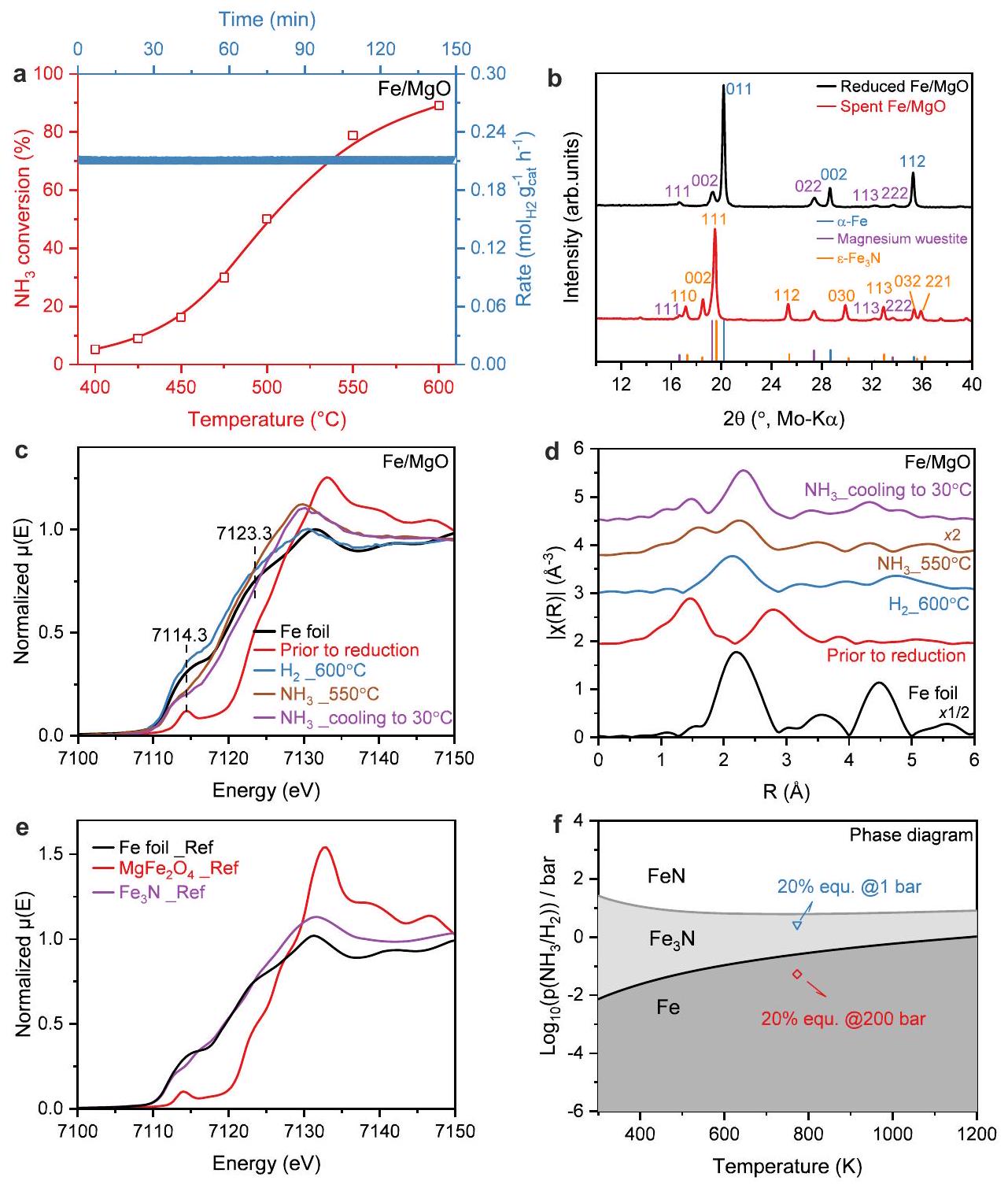
Fig. 2 | Catalytic activity and structural properties of catalyst.
a Catalytic activity of for ammonia decomposition reaction: conversion (left) and formation rate with time-on-stream (TOS) at (right). b XRD patterns of the freshly reduced and the spent catalyst after reaction condition without exposure to the air. References: (ICSD: 52258), Magnesium wüstite (ICSD: 181215), (ICSD: 79981). Operando XAS measurement of the Fe/MgO catalyst: (c) XANES spectra at the Fe K-edge, (d) Fourier transformed -weighted EXAFS spectra in R-space at the Fe K-edge. The R-space EXAFS spectra are plotted without phase correction. The corresponding -space
EXAFS spectra were plotted in Supplementary Fig. 13. e Reference Fe K-edge XANES spectra of Fe metal, and , which were retrieved from the SPring-8 BL14B2 XAFS Standard Sample Database. The corresponding -space and R-space EXAFS spectra were plotted in Supplementary Fig. 14. Calculated phase diagram of nitridation of iron. The blue dot represents the condition approaching to of equilibrium for decomposition of at under 1 bar while the red dot represents the condition approaching to of equilibrium for reaction of and at under 200 bar. Source data are provided as a Source Data file.
results thus indicate that a considerable fraction of at least of the total iron content is difficult to reduce and remains in the solid solution state. Nevertheless, for the sake of brevity, we will denote the support phase as MgO and reduced catalysts as .
Highly-loaded iron catalyst: catalytic performance and characterization
The phase composition of the catalyst on the nano-scale has been studied by STEM-EDS. As shown in Fig. 1 e1, a large isolated particle ( ) was surrounded by a number of smaller particles. Based on the EDS results (Fig. 1 e2-e6), the large particle was assigned to iron metal and the smaller surrounding particles to the oxide phase ( ) O . The microstructure of these composite catalysts was further investigated with TEM and the aforementioned
intermediate microstructure between a bulk and a supported catalyst becomes apparent from Fig. 1f and Supplementary Fig. 23a1 showing typical aggregates of larger metallic iron and smaller oxidic support particles. The iron particle size analysis revealed a monomodal, but broad size distribution with an average particle size around (Fig. 1g and Supplementary Fig. 23a2). As noted before, opposed to conventional supported catalysts, the oxide particles do not form a typical continuous porous material, but are individually dispersed between the larger metal particles acting as spacers between them, thus rather functioning like a typical structural promoter in bulk catalysts. Such an “intermediate microstructure” of highly loaded base metal catalysts is known for example from the industrial catalyst for methanol synthesis as a result of a similar co-precipitation method .
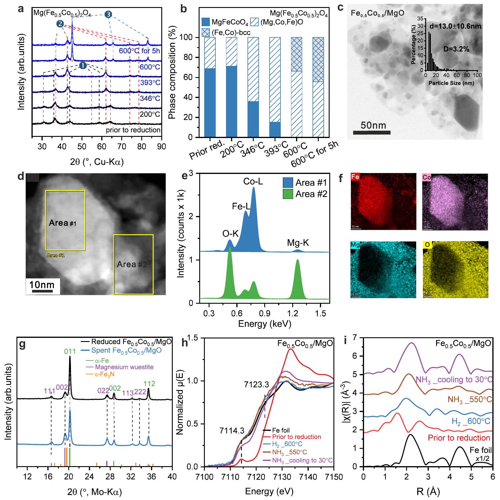
Fig. 3 | Structural properties of the / catalyst. a In situ XRD of the reduction process and (b) the corresponding phase composition transformations during reduction based on Rietveld refinement of the , in (a) is phase, 2 is wüstite-like phase, 3 is phase. c Representative BF-STEM image of the catalyst and the FeCo alloy particle size distribution, which was determined by the evaluation of at least 400 particles (inset in (c)). The error bar represents the standard deviation through particle size statistical analysis. The STEM image and (f) the corresponding EDS spectra collected at Area #1 and #2 (e) as well as EDX maps, which are related to
The catalytic performance of the catalyst in diluted ammonia showed stable activity in a temperature window from 400 to (Fig. 2a). The steady-state catalyst mass-normalized production rate at reached (Fig. 2a), which turned out to be in the moderate to upper range of performance reported previously for Fe-based catalysts (Supplementary Table 5). A reason for this relatively low activity was found in the structural analysis of the spent catalyst with using ex situ XRD and XES and operando XAS. The XRD pattern of spent catalyst without exposure to the air showed clear reflections of and iron-magnesium-wüstite, with comparison to the freshly reduced (Fig. 2b). Furthermore the valence-to-core X-ray emission spectrum (VtC XES) of the spent Fe catalyst is also consistent with the nitridation and supports the transformation of iron to iron nitride after catalysis (Supplementary Fig. 10) .
To investigate the reason and check for possible reversible phase transformations, operando X-ray absorption spectroscopy (XAS) was
employed to study the electronic and geometric structure of Fe and Co species in the catalysts during the reaction. Figure 2c, d shows X-ray absorption near-edge structure (XANES) spectra and Fourier transforms (FTs) of the extended X-ray absorption fine-structure (FT-EXAFS) spectra collected for the catalyst under reaction conditions at the Fe K-edge. The XANES of showed a sharp pre-edge feature at 7114.3 eV resulting from the 1 s to 3 d transitions , and a rising edge position at 7123.3 eV (determined by energy position at half absorption of the edge in normalized XANES), which is shifted by -3.8 eV compared to Fe foil. The edge shape and position of the pre-catalyst are nearly identical to those of the commercial spinel reference (Fig. 2e), which has a mixture of tetrahedrally and octahedrally coordinated sites in the lattice. After reduction in at , the XANES edge position of the reduced catalyst shifted back to a position very close to that of metallic Fe and the EXAFS spectra can be fitted by two paths derived from the structure (at and , respectively) without contribution from coordination (Supplementary Fig. 16e, f and Supplementary Table 3), suggesting that metallic Fe is the predominant component in the bulk. This shows that the reduction reaches completeness faster in the quartz capillary reactor used for XAS measurement compared to the fixed bed reactor likely due to the much smaller amount of sample. Switching to atmosphere at led to clear changes in the XANES region as compared to the reduced catalyst, including the decreased intensity of pre-edge feature between 7112 and 7118 eV , disappearance of the shoulder peak at around 7125 eV and a rising white line feature at about 7129 eV (Fig. 2c). In the corresponding EXAFS spectra, a much shorter coordination from a light scattering atom was found, along with a shift in the Fe-Fe shell to a longer distance (Fig. 2d). Based on the EXAFS fitting results, the first coordination shell attributed to a Fe-N/O scattering path with a coordination number (CN) of at (Supplementary Fig. 16g, h and Supplementary Table 3), which is shorter than the typical bond in both and oxides, but also longer than the distances in the known Fe nitride categories (Supplementary Table 4). The second shell is fit as an Fe-Fe scatterer with a CN of and an average distance of , which is very similar to the Fe-Fe distance of in (Supplementary Fig. 16g, h, Supplementary Table 3-4). The noticeable differences in EXAFS indicate significant structural changes that on a first sight resemble formation of an oxide from the metallic phase. However, this is excluded by the XANES edge position of MgO under decomposition condition, which is not consistent with conversion to an oxide phase and lead to the most conceivable conclusion that the changes in electronic structure (from the XANES) and in coordination environment (from the EXAFS) were caused by nitridation of the metallic Fe phase. Such phenomenon could also be supported by comparing the XANES and EXAFS spectra of and Fe foil references (Fig. 2e). In the last condition when catalyst was cooled down from 550 to in , the absorption edge shifted by to higher energy, while still maintaining most of the edge features and a relatively more prominent pre-edge shoulder peak (Fig. 2c). Despite large differences between the Debye-Waller factors ( ) at 550 and , the CNs for both and bond were just slightly increased (Supplementary Fig. 16g-j, Supplementary Table 3). However, a discernible reduction in the first shell distance to was observed from the EXAFS fitting results, while the second shell Fe-Fe distance remains constant at , which is still similar to the Fe-Fe distance of in (Supplementary Fig. , Supplementary Table 3). Such structural transformations hint to a transformation of the nitride formed at to a more stable phase at room temperature.
Operando XAS, ex situ XRD, and XES thus were all consistent with the hypothesis that the working state of the monometallic Fe catalysts
in ammonia decomposition is an Fe nitride phase, even in diluted ammonia. Indeed, DFT calculations provide further support for the nitridation of Fe under typical ammonia decomposition conditions ( approaching to equilibrium at , 1 bar) as shown in Fig. 2f and Supplementary Fig. 25. Importantly, this is different from typical ammonia synthesis (e.g. 200 bar, , Supplementary Fig. 25), where the bulk-unnitrided “ammonia iron” was reported to be stable . This indicates that also the surface chemistry, including key parameter like the nitrogen binding energy, might be different for iron catalysts used in ammonia decomposition compared to ammonia synthesis. We calculated the nitrogen binding energy of to be -0.37 eV relative to gas-phase , which is lower than both the value for metallic Fe (considered too strong) and metallic Ru (considered optimal) . Thus, the challenge in Fe-based ammonia decomposition is either to increase the nitrogen binding energy of Fe nitride or to suppress its nitridation while lowering the nitrogen binding strength of unnitrided Fe at the same time.
Bimetallic catalyst: alloying iron with cobalt
We have chosen the latter approach and studied the alloying of Fe with a second base metal that shows a lower nitrogen binding energy than Fe and Ru, and at the same time is not forming nitrides easily. Hence, we chose cobalt and employed the above-described synthesis method to synthesize spinel pre-catalysts (synthesis recipe: Supplementary Fig. 1, XRD: Supplementary Fig. 2) with different Fe:Co ratios yielding bi-metallic catalysts and in addition to the already presented . XRD characterization shows that the reduced cobalt-containing catalysts are comprised of a single metallic phase, which depending on is , bcc alloy, or fcc Co , together with an oxidic wüstite-like phase, which still contains some transition metal cations similar to the pure catalyst (Supplementary Fig. 7).
The comparative characterization data for the catalyst ( pre-catalyst) is shown in Fig. 3. In situ XRD of the activation behavior was similar (Fig. 3a, Rietveld refinements in Supplementary Fig. 9b and Supplementary Table 2), however, the precatalyst was found to be not entirely phase-pure, but it contained wüstite-like already before reduction, whose phase content increased with the activation (Fig. 3b). TEM showed that the catalyst features a similar “intermediate microstructure” like the sample being comprised of larger metal and smaller oxide particles (Fig. 3c). The metal particle sizes show a broad distribution and were found to be slightly smaller than in catalyst with a size of (Fig. 3c inlet). Importantly, the local STEM-EDS measurements (Fig. 3d) and EDS maps (Fig. 3e, f) demonstrate that the big metal particles (area #1) contain both metals Fe and Co , which are homogeneously distributed in one particle. This supports the formation of bimetallic alloy particles. Meanwhile the surrounding particles (area #2) mostly contain Mg and O with a small fraction of Fe and/or Co supporting the formation of wüstite like . The EDS maps and the in situ XRD for activation process of proved the similar “intermediate microstructure” as the catalyst (see more information in Supplementary Fig. 9a, Supplementary Fig. 11, and Supplementary Table 2).
The XRD pattern of spent catalyst after ammonia decomposition reaction showed similar reflections to the freshly reduced , suggesting metallic FeCo alloy remained during reaction without nitridation (Fig. 3g). Operando XAS studies of catalysts were also carried out under the same reaction conditions. The pre-catalyst measured at exhibited similar XANES and EXAFS spectra to the precatalyst. Upon exposing to catalyst was almost fully reduced to metallic FeCo , featuring the absorption edge nearly overlapping with that of Fe foil. A similar transformation was observed from the corresponding Co K-edge XANES and EXAFS results
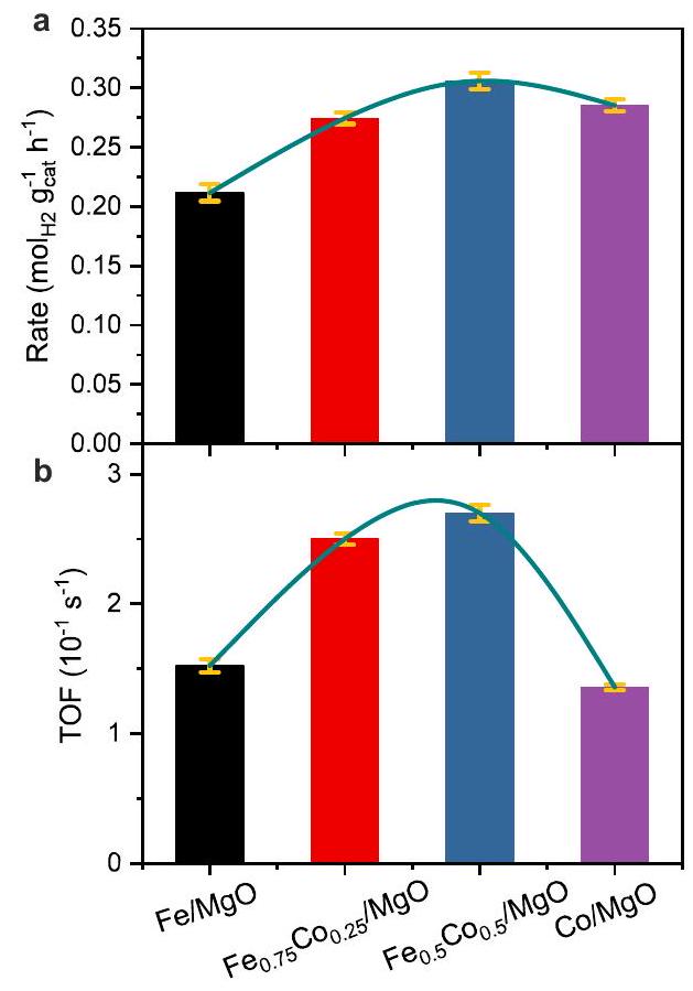
Fig. 4 | Catalytic performance of various catalysts and their relationship with the corresponding calculated dissociative adsorption energy. Steady-state reaction rate of production (a) and TOF (b) of the four catalysts for ammonia decomposition at . c Calculated TOF of ammonia decomposition at bar, as a function of the dissociative adsorption energy as reported in the literature . d Experimental TOFs of the four catalysts as a function of the corresponding dissociative adsorption energy as obtained from DFT calculations. Note that the Fe pure point is
hypothetical, as our measurements indicate that is the active material for this catalyst, purple dashed curve is there to guide eyes. The error bars of reaction rates / TOFs represents standard deviation through two repeated measurements, while the error bars of calculated dissociative adsorption energy represents the calculated standard deviation of the appropriately weighted difference of ensembles provided in the BEEF-vdW functional . Source data are provided as a Source Data file.
(Supplementary Fig. 12). Unlike the Fe/MgO catalyst, no noticeable changes of could be observed in either in the XANES or in the EXAFS spectra during decomposition reaction at both Fe K -edge and Co K -edge with the comparison to the condition under reduction at (Fig. 3h, i and Supplementary Fig. 12), providing experimental evidence that introducing Co to the catalyst significantly enhances the stability of the metallic Fe phase against bulk nitridation. To assign the observed suppression of nitridation to the formation of the alloy, a physical mixture of and was also tested in ammonia decomposition. The activity of this mixture was between the activity of pure and (Supplementary Fig. 22a). After ammonia decomposition, the XRD of the spent catalyst mixture showed the disappearance of the reflections while crystalline Fe nitrides formed, including and (Supplementary Fig. 22b). Therefore, the suppression of iron nitridation can be assigned to the formation of the alloy and not to the presence of unalloyed cobalt alone.
Bimetallic catalyst: relationship between activity and N-binding energy
Comparing the catalytic performance of all four catalysts, the catalyst showed the lowest ammonia conversion for the reasons outlined above. The substitution of with Co in resulted in a remarkable improvement in the activity (Supplementary Figs. 17-18). However, the catalyst with the full substitution of Fe exhibited similar ammonia conversion as the bimetallic catalysts. In order to take the different metal dispersions of the four catalysts into account, the reaction rates of formation at were carefully evaluated and compared among these four catalysts, first on a catalyst-mass basis (Fig. 4a and Supplementary Fig. 18). The steady-state catalyst mass-normalized production
rate of the catalyst was clearly increased to and for the two Co substituted samples, and , respectively. For the pure catalyst, the rate decreased slightly again to giving rise to a volcano-like evolution of the rates with increasing Co content (Fig. 4a). Furthermore, the catalyst kept a stable reaction rate at over 1000 min in a durability test (Supplementary Fig. 19). To evaluate the intrinsic rates, the differences in metal dispersion evaluated by STEM have to be taken into account (Supplementary Fig. 23). TOF values have been calculated based on the metal particle size distributions assuming fully exposed particle surfaces and equal activity of all surface atoms. These might not be fully realistic boundary conditions, but the systematic errors can be considered to be similar for all catalysts enabling a comparison with theoretical calculations regarding the trends among the four catalysts. Additional chemisorption combined with TPD were performed to determine the exposed metal surface based on the chemisorption capacity. Assuming the same adsorbate stoichiometry for all catalysts, the obtained metal dispersions follow the trend , which is similar to the trend obtained from the TEM particle size distribution: (Supplementary Figs. 23 and 24). However, the chemisorption-derived dispersion are approximately six times lower than the ones obtained from the particle size distribution. The reasons could be oxide coverage not accounted for in the TEM evaluation, pre-mature removal of adsorbed hydrogen during the purging before TPD, and/or uncertainties in adsorbate stoichiometry. Therefore, while the general relative trend among the catalysts can be confirmed by chemisorption, we will base the following discussion
of the absolute values on the TEM-derived dispersions regarding them as a lower limit for the corresponding TOF values, which would be even higher if derived from the chemisorption data.
Importantly, the TOFs of these four catalysts at show the same volcano-shaped variation with increasing Co content like the mass-normalized rate data as illustrated in Fig. 4b, but the superiority of the bimetallic catalysts is much clearer. Interestingly, both bimetallic catalysts and show almost the same intrinsic activity (TOF ) for ammonia decomposition. However, showed a much smaller TOF of , which is comparable to . From this, we conclude that already small amounts of Co promote the monometallic Fe catalysts very efficiently by suppressing nitride formation. Increasing the Co content towards monometallic Co catalysts does not lead to a further improvement in the intrinsic activity. The apparent activation energy ( ) was calculated from Arrhenius plots of these four catalysts (Supplementary Fig. 20) and was found to be slightly lower for and compared to the two bimetallic FeCo catalysts in accordance with the volcano-shaped trend. As the difference was not large ( ) and hardly significant, it can be assumed that ammonia decomposition operates via a similar reaction mechanism for iron- and cobalt-monometallic or bimetallic catalysts in line with the literature reporting that the rate-determining step is the nitrogen desorption step on Fe – and Co -based catalysts . However, the emerging volcanoshape trend in activation energy can be related to the difference in nitrogen binding energy , as we will show through the use of DFT calculations. Regarding the very similar catalysts and , we also measured the activation energy of in a gas stream with a higher concentration of , which resulted in a by around lower of in agreement with a low nitrogen binding energy for Co (Supplementary Fig. 21).
The reaction mechanism of ammonia synthesis has been investigated using DFT calculations . Importantly, through the use of scaling relations for the adsorption energies of intermediates and transition states , activity volcanoes could be established where the theoretical turnover frequency is plotted as a function of the nitrogen binding energy to the steps of transition metal surfaces . Boisen et al. established an activity volcano for ammonia decomposition as a function of the reaction energy of dissociative adsorption and showed that this differs from that usually obtained for ammonia synthesis as the conditions in terms of temperature and pressures are different (Fig. 4c shows their original work at bar, and . In their work, they developed the concept of combining strong and weak binding elements to nitrogen, that we follow in this work. They suggested CoMo as an attractive bimetallic combination for ammonia decomposition and they and others found experimentally that nitride was formed in the bulk and is the active phase, which is not the case in the FeCo catalysts of this work, which remain unnitrided.
We employed DFT to calculate the nitrogen binding energies on the surfaces of the four catalysts used herein and interpreted them in the light of the volcano established by Boisen et al. Using our methodology we obtained nitrogen binding energies that differ only slightly from those reported in the original work (for we calculated -0.16 eV compared to . An activity volcano using the experimentally obtained TOFs (normalized to the metal surface area) as a function of the calculated nitrogen binding energies for various Fe and FeCo surfaces is shown in Fig. 4d, using the same x-axis as in 4c. As can be seen from Fig. 4d, our data suggests a volcano type behavior analogous to that predicted by Boisen et al. Note, that the data for (strong binding left side of the volcano) is only hypotheticalnce under ammonia decomposition conditions, the monometallic catalysts were nitridated to form the stable bulk , as suggested by operando XAS, ex situ XRD, and XES (Fig. 2b-d and Supplementary Fig. 10). This moves the nitrogen binding energy to the weak binding side and explains the low activity observed for our iron
catalyst. If nitridation could be avoided, should exhibit a higher activity as evident from Fig. 4c, d. has also a rather weak nitrogen binding energy and is hence a poor catalyst for both, ammonia synthesis and decomposition. Alloying iron with cobalt, however, leads to surfaces with nitrogen binding energies that are close to the top of the theoretical ammonia decomposition volcano. This is also the outcome of our experimental efforts that show that FeCo alloys have a higher activity than both, and Co . The effect of alloying iron with cobalt is thus twofold, (1) suppression of nitridation and (2) weakening of the nitrogen binding energy.
In summary, we have found that the high-loading alloyed FeCo bimetallic catalysts with “intermediate microstructure” between supported and bulk catalysts synthesized by our spinel approach through co-precipitation could efficiently release from decomposition. In-depth and complementary characterization uncovered the nitridation of Fe from surface to bulk under ammonia decomposition, which is different from ammonia synthesis. DFT calculations provided further evidence for the nitridation of Fe and revealed that surfaces exhibit too weak binding energies and are thus less active. By alloying Fe with Co , this nitridation could be suppressed and the nitrogen binding energy is additionally influenced such that the binding energies move closer to the top of the activity volcano, leading to a highly active and stable catalytic performance. This work also indicates that alloying Fe by other metals with weak nitrogen adsorption energy provides a simple and general approach to fabricating a highly active and unnitrided catalyst for ammonia decomposition reaction.
Methods
Materials
For the synthesis of the catalyst precursors the following commercially available chemicals were used without further purification: Cobalt (II) nitrate hexahydrate ( p.a., ACS, Carl Roth GmbH & Co. KG), iron (II) sulfate heptahydrate ( p.a., ACS, Carl Roth GmbH & Co. KG), iron (III) nitrate nonahydrate ( p.a., ACS, Alfa Aesar GmbH), magnesium nitrate hexahydrate ( , ACS, Alfa Aesar GmbH), sodium carbonate (p.a., AppliChem GmbH) and sodium hydroxide ( , VWR International BVBA).
Catalyst synthesis
spinel catalysts were prepared by co-precipitation of LDHs/hydroxide in an automated laboratory reactor system (Optimax synthesis workstation, Mettler Toledo). During co-precipitation, the metal solution contained three equal concentrations of ( ) of , where the ratio of determines the ratio in . The aqueous and solution serve as a precipitation agent. The pH during co-precipitation is 10.0 for as well as and is 10.5 for with an aging time of 24 h at . For solution of and solution of , the ratio of is solution serve as a precipitation agen. The pH during co-precipitation is 11.0 with an aging time of 1 h at .
After washing with water until the conductivity of the supernatant was below , then after drying, the precursors were calcined at for 3 h and further isothermally reduced in prior to the reaction.
Catalyst characterization
Iron, cobalt and magnesium contents in the spinel samples were determined by atomic absorption spectroscopy (AAS) (Thermo Electron Corporation, M-Series). The sodium contents in the samples were determined by Inductively Coupled Plasma Optical Emission spectroscopy (ICP-OES) (Avio 200 von PerkinElmer). Thermogravimetric measurements (TG) were performed in a NETZSCH STA 449F3 thermal analyzer. In a corundum crucible ca. 50 mg of the LDH / hydroxide
precursors were heated in synthetic air ( in Ar ) from to with a linear heating rate of adsorptiondesorption experiments of the LDH and spinel precursors were conducted with a NOVA3000e setup (Quantachrome Instruments) at after degassing the samples at for 2 h in vacuum. BET (Brunauer Emmet Teller) surface areas were calculated from data between 0.05 and 0.3. Pore volumes and pore size distribution were determined by applying the BJH (Barrett-Joyner-Halenda) method. Powder X-ray diffraction (XRD) patterns of the LDH and spinel phases were recorded on a Bruker D8 Advance diffractometer in BraggBrentano geometry using a position-sensitive LYNXEYE detector (Ni-filtered CuK radiation). A range from to , a counting time of 2.96 s and a step width of was applied. The samples were dispersed with ethanol on a glass disc inserted in a round PMMA holder, which was subjected to a gentle rotation during scanning. Powder XRD patterns of the reduced catalysts were recorded on a STOE transmission diffractometer STADI P in Debye-Scherrer geometry at room temperature using a curved image-plate position sensitive detector ( , crystal monochromator filtered MoK radiation). A range of and a step width of was applied. The samples were transferred from the reactor into a glove box under argon, then pestled and filled into a capillary sample holder ( 0.2 mm Ø). After sealing the capillary with vacuum grease, the sample holder was discharged from the glove box and the plugged opening of the capillary was sealed by melting to prevent sample contamination with air. Environmental scanning electron microscope (SEM) studies of spinel pre-catalysts were carried out with a Quanta ESEM 400 FEG microscope, equipped with a FEI detector and an Apreo S LoVac microscope (Thermo Fisher Scientific) which is equipped with two backscattering electron detectors. All samples were surface coated with prior to the measurements. The nonresonant Fe K X-ray Emission Spectroscopy (XES) data were collected at beamline ID26 of the European Synchrotron Radiation Facility (ESRF), which operates at 6 GeV with 200 mA ring current. A Si(111) double-crystal monochromator was used upstream for energy selection and calibrated to the first inflection point of an Fe foil set to 7111.2 eV . The incident beam energy was set to 7800.0 eV (above the Fe K -edge at 7112 eV ) to excite the sample non-resonantly. The beam size at the sample was and the photon flux was (without attenuation). The non-resonant XES spectra were collected with a 1 meter radius Johann spectrometer equipped with five Ge(620) crystal analyzers and an avalanche photodiode (APD) detector aligned on intersecting Rowland circles. The spectrometer was internally calibrated using the emission line of at 7060.6 eV . All samples were diluted in boron nitride (BN) and measured in a liquid helium cryostat operated at 20 K . All XES spectra were collected between 7020.0 eV and 7130.0 eV with a uniform step size of 0.25 eV and were normalized to a unit area of 1 over the mainlines region between 7020.0 eV to 7080.0 eV . -Temperature programmed reduction ( -TPR) experiments were performed in a BELCAT-B (BEL Japan, Inc.) catalyst analyzer at a linear heating rate of between room temperature and . This temperature was held for 15 min before cooling down. All samples were dried at for 60 min in prior to the experiments. To remove the from the gas stream an in-line molecular sieve was used before reaching a built-in thermal conductivity detector. A flow rate of and in , Air Liquide) was applied for the reduction process. For all experiments with this catalyst analyzer, of the sample with a sieve fraction of was prepared. A quantitative analysis of the consumption was achieved by integrating the TCD signal obtained by the reduction of three different amounts of commercial CuO for calibration. It was used since CuO undergoes a complete reduction to . -Temperature programmed desorption ( -TPD) experiments for obtaining information of metal dispersion were
performed in a BELCAT-II (BEL Japan, Inc.) at a linear heating rate between and . All samples (around 20 mg for each sample) were isothermally reduced at for 5 h in ( , Air Liquide) prior to the experiments, and purged with argon during cooling to . The atmosphere was switched back from Ar to at , then the sample was cooled to and kept in for adsorption at for 1 h . Afterwards, the sample was purged by Ar at for 2 h to remove in gas phase and physiosorbed . Then, the samples were heated in to and the concentration of in the exhaust was monitored by a mass spectrometry (QMG 220, Pfeiffer Vacuum GmbH). The chemisorption data were used for calculating the values of metal dispersion assuming a stoichiometric ratio of to iron and / or cobalt of 2.
In situ XRD measurements
The data were collected on a STOE theta/theta X-ray diffractometer (Cu radiation, secondary graphite monochromator, scintillation counter) equipped with an Anton Paar XRK 900 in situ reactor chamber. The gas feed was mixed by means of Bronkhorst mass flow controllers, using in helium at a total flow rate of . Due to the low time resolution (ca. 10 h per scan), all XRD measurements were performed at to avoid continuous reduction of the sample during the data collection (“quasi in situ”). The samples were reduced in an in situ chamber with a ramp rate of until the respective target temperature was reached, followed by fast cooling ( ) and XRD measurement at . Subsequently, the sample was heated again at up to the previous target temperature, where the ramp rate was changed to again until the next target temperature was reached, followed again by rapid cooling and XRD measurement.
STEM-EDS-map measurements
STEM-EDS micrographs of the spinel catalysts and freshly reduced catalysts were generated, using a Thermo Scientific Talos F200X. The transmission electron microscope was equipped with a high brightness field emission gun (X-FEG) and 4 SDD EDX detectors, giving together a detection area of 0.9 sr . The electron beam energy was 200 keV and the beam current 50 pA . The point resolution of the microscope was Å. In order to reduce artifacts induced by electron beam on the sample, the multiple frame approach was applied. This means that the electron beam was scanned across the region of interest several times, with short acquisition times ranging from 20 to per pixel, and the signal was integrated later. To compensate for sample drift during EDS acquisition, Velox drift correction was applied by cross-correlation after each frame. The mono-metal / bi-metal particle size distribution was determined by the evaluation of at least 400 particles.
Dispersion of mono- / bi-metal nanoparticles: calculation from STEM results
With the known diameter ( ) of the individual metal nanoparticles ( ), as measured by STEM, the volume-area mean diameter ( ) was calculated according to Eq. (1). From this relation, one can easily calculate the metal dispersion ( ), which is defined by the ratio of surface atoms to the total number of atoms in the hemispherical metal particle ( volume metal atom, surface area metal atom) as shown in Eq. (2).
Kinetic measurements
Prior to the catalytic steady-state measurements, 20 mg of the spinel catalysts ( ) were isothermally reduced for 5 h at , Air Liquide, , ). Afterward, the freshly reduced samples were cooled down to and nitridated for 5 h in a mixture of in He , Air Liquide, . The nitridation step was initially added for catalyst to obtain stable catalytic activity and finally employed to all catalysts to maintain comparability. Then steady-state catalytic ammonia decomposition measurements were conducted between 400 and . Firstly, the samples were cooled down to at a gas flow of which was directed through the catalyst bed. After measuring at , the samples were heated up stepwise to 425,450 , and held at each temperature for 3 h . A mass spectrometer (QMG220, Pfeiffer Vacuum GmbH) was calibrated for , and taking helium as the internal standard to perform a quantitative analysis during catalysis. A Micro GC Fusion from Inficon was calibrated for and to perform analysis. The mole and corresponding volume changes of the gas mixture due to reaction and its effect on the conversion data was neglected as it is limited to the only in the gas feed and the of diluent He fraction remain. The conversions of all catalysts at (89-95%) are approaching, but remain below the equilibrium conversion ( ). The metal-massnormalized production rates and the apparent activation energy ( ) were calculated at low conversion approaching differential reaction conditions. Calculations of the Weisz-Prater criterion and Mears’ criterion confirm the absence of mass transfer limitations for this catalytic system as described in the Supplementary Information.
Operando XAS measurements
Measurements were performed at the CAT part of the CAT-ACT beamline at the KIT light source in Karlsruhe, Germany . The samples were typically diluted with boron nitride, pressed into pellets, crushed and mesh-sieved between 100 and . For the measurements, the samples were loaded into a quartz capillary ( 1.5 mm o.d., 0.02 mm wall thickness, bed length) and mounted on top of a hot air blower . The gas flow rate through the capillary was , and the outlet gas composition was monitored by a Pfeiffer Vacuum OmniStar GSD 320 mass spectrometer (example for on-line analysis in Supplementary Fig. 15). The X-ray absorption near edge structure (XANES) and the extended X-ray absorption fine structure (EXAFS) spectra were collected at the Fe K-edge ( 7112 eV ) (for both and pre-catalysts) and Co K -edge (only for pre-catalyst), in transmission mode with ion chambers as detectors. The following experiments were done on this sample after the initial loading: Reduction by in He from (with ramp rate) and dwelling of 8 h , cooling down to and exposure to , ramping to under and dwelling of 2 h , cool down to under environment. XANES spectra and an extended energy range for the EXAFS spectra were collected and at the end of that stage. The collected data were normalized using the Athena code within the Demeter package (version 0.9.26) . The EXAFS part of the spectra was obtained by converting the normalized data from energy space to space and weighted by , and , then Fourier transformed in the selected k range (depending on data quality) with a Hanning window. The fitting of the data was then performed in R-space with Artemis software of the same package with selected structural models for all k -weighted datasets.
DFT calculations
DFT calculations in this work were carried out using the Vienna Ab Initio Simulation Package (VASP) in connection with the Atomic Simulation Environment (ASE) . A plane-wave basis set with a cutoff
energy of 450 eV , the projector augmented wave method (PAW) and the Bayesian Error Estimation Functional with van der Waals correlations (BEEF-vdW) exchange correlation functional were used. The lattice constants were optimized using an energy cutoff of 450 eV and a (for and FeCo ), (for ) Monkhorst Pack k -point sampling. The optimize lattice constants are given in Supplementary Table 6.
The kinetic energy cutoff for all slab calculations was 450 eV . The and systems were modeled by infinite slabs consisting of four layers thick super-cells. Cobalt surfaces were modeled using four layer thick large unit cell, with one row of Co atoms in the y -direction removed from the top layer creating A and B edges. Iron nitride was modeled using a four layer thick surface with 6 Fe and 2 N atoms in each layer. All slab models were separated by in the direction. In all calculations the bottom two layers were kept fixed at the bulk positions while the top two layers were allowed to relax during geometry optimizations. The convergence criterion for geometry optimizations was a maximum force of . The Brillouin zones were sampled using a (for , , ) and (for ) Monkhorst-Pack k-point grid for . Spin polarization was considered in calculations. Adsorption energies of nitrogen were calculated relative to gas-phase . Zero-point-energy corrections were calculated from vibrational analyses carried out in the harmonic approximation using a finite difference with a magnitude of for the displacements. The coordinates of all structures are given in the Supplementary Information.
Data availability
The data generated in this study are provided in the Supplementary Information/Source Data file. Source data are provided with this paper.
References
Erisman, J. W., Sutton, M. A., Galloway, J., Klimont, Z. & Winiwarter, W. How a century of ammonia synthesis changed the world. Nat. Geo. 1, 636-639 (2008).
Schüth, F., Palkovits, R., Schlögl, R. & Su, D. S. Ammonia as a possible element in an energy infrastructure: catalysts for ammonia decomposition. Energy Environ. Sci. 5, 6278-6289 (2012).
Tamaru, K. A “new” general mechanism of ammonia synthesis and decomposition on transition metals. Acc. Chem. Res. 21, 88-94 (1988).
Schlogl, R. Ammonia synthesis. in Handbook of Heterogeneous Catalysis 2nd edn, Vol. 3 (eds Ertl, G., Knotzinger, H., Schuth, F. & Weitkamp, J.) Ch. 2501-2575 (Wiley-VCH Weinheim, 2008).
Yin, S. F., Xu, B. Q., Wang, S. J., Ng, C. F. & Au, C. T. Magnesia-carbon nanotubes (MgO-CNTs) nanocomposite: Novel support of Ru catalyst for the generation of -free hydrogen from ammonia. Catal. Lett. 96, 113-116 (2004).
Chang, F., Gao, W., Guo, J. & Chen, P. Emerging materials and methods toward ammonia-based energy storage and conversion. Adv. Mater. 55, 2005721 (2021).
Chen, C. et al. Ru-based catalysts for ammonia decomposition: a mini-review. Energy Fuels 35, 11693-11706 (2021).
Yin, S.-F. et al. Investigation on the catalysis of -free hydrogen generation from ammonia. J. Catal. 224, 384-396 (2004).
Bell, T. E. & Torrente-Murciano, L. production via ammonia decomposition using non-noble metal catalysts: a review. Top. Catal. 59, 1438-1457 (2016).
Kiełbasa, K., Pelka, R. & Arabczyk, W. Studies of the kinetics of ammonia decomposition on promoted nanocrystalline iron using gas phases of different nitriding degree. J. Phys. Chem. A 114, 4531-4534 (2010).
Tseng, J.-C. et al. Tracking the active catalyst for iron-based ammonia decomposition by in situ synchrotron diffraction studies. Chem. Cat. Chem. 10, 4465-4472 (2018).
Lu, A.-H. et al. Spatially and size selective synthesis of Fe-based nanoparticles on ordered mesoporous supports as highly active and stable catalysts for ammonia decomposition. J. Am. Chem. Soc. 132, 14152-14162 (2010).
Ji, J. et al. Towards an efficient catalyst using metal amine metallate as an active phase precursor: Enhanced hydrogen production by ammonia decomposition. Int. J. Hydrog. Energy 39, 12490-12498 (2014).
Zaman, S. F. et al. Ammonia decomposition over citric acid chelated and catalysts. Int. J. Hydrog. Energy 43, 17252-17258 (2018).
Kirste, K. G. et al. Cox-free hydrogen production from ammonia mimicking the activity of Ru catalysts with unsupported Co -Re alloys. Appl. Catal. B Environ. 280, 119405 (2021).
Ortega, K. F. et al. Ammonia decomposition and synthesis over multinary magnesioferrites: promotional effect of Ga on Fe catalysts for the decomposition reaction. Chem. Cat. Chem. 9, 659-671 (2017).
Rein, D., Friedel Ortega, K., Weidenthaler, C., Bill, E. & Behrens, M. The roles of Co-precipitation ph, phase-purity and alloy formation for the ammonia decomposition activity of Ga-promoted catalysts. Appl Catal. A Gen. 548, 52-61 (2017).
Lorenzut, B., Montini, T., Bevilacqua, M. & Fornasiero, P. FeMobased catalysts for production by decomposition. Appl. Catal. B Environ. 125, 409-417 (2012).
Zhang, J. et al. Individual alloy nanoparticles on carbon nanotubes: structural and catalytic properties. Nano Lett. 8, 2738-2743 (2008).
Simonsen, S. B., Chakraborty, D., Chorkendorff, I. & Dahl, S. Alloyed Ni-Fe nanoparticles as catalysts for decomposition. Appl. Catal. A Gen. 447-448, 22-31 (2012).
Kowalczyk, Z., Sentek, J., Jodzis, S., Muhler, M. & Hinrichsen, O. Effect of potassium on the kinetics of ammonia synthesis and decomposition over fused iron catalyst at atmospheric pressure. J. Catal. 169, 407-414 (1997).
Jedynak, A., Kowalczyk, Z., Szmigiel, D., Raróg, W. & Zieliński, J. Ammonia decomposition over the carbon-based iron catalyst promoted with potassium. Appl. Catal. A Gen. 237, 223-226 (2002).
Ganley, J. C., Thomas, F. S., Seebauer, E. G. & Masel, R. I. A priori catalytic activity correlations: the difficult case of hydrogen production from ammonia. Catal. Lett. 96, 117-122 (2004).
Dahl, S., Logadottir, A., Jacobsen, C. J. H. & Nørskov, J. K. Electronic factors in catalysis: the volcano curve and the effect of promotion in catalytic ammonia synthesis. Appl. Catal. A Gen. 222, 19-29 (2001).
Boisen, A., Dahl, S., Nørskov, J. K. & Christensen, C. H. Why the optimal ammonia synthesis catalyst is not the optimal ammonia decomposition catalyst. J. Catal. 230, 309-312 (2005).
Schlögl, R. Catalytic synthesis of ammonia-a “never-ending story”? Angew. Chem. Int. Ed. 42, 2004-2008 (2003).
Kandemir, T., Schuster, M. E., Senyshyn, A., Behrens, M. & Schlögl, R. The haber-bosch process revisited: on the real structure and stability of “ammonia iron” under working conditions. Angew. Chem. Int. Ed. 52, 12723-12726 (2013).
Su, Q. et al. Layered double hydroxides derived nix(mgyalzon) catalysts: enhanced ammonia decomposition by hydrogen spillover effect. Appl. Catal. B Environ. 201, 451-460 (2017).
Ge, X., Li, M. & Shen, J. The reduction of and complex oxides studied by temperature-programmed reduction combined with in situ mössbauer spectroscopy. J. Solid State Chem. 161, 38-44 (2001).
Behrens, M. Meso- and nano-structuring of industrial catalysts. J. Catal. 267, 24-29 (2009).
Behrens, M. et al. The active site of methanol synthesis over industrial catalysts. Science 336, 893-897 (2012).
Lancaster, K. M. et al. X-ray emission spectroscopy evidences a central carbon in the nitrogenase iron-molybdenum cofactor. Science 334, 974-977 (2011).
Pollock, C. J. & DeBeer, S. Insights into the geometric and electronic structure of transition metal centers from valence-to-core x-ray emission spectroscopy. Acc. Chem. Res. 48, 2967-2975 (2015).
Westre, T. E. et al. A multiplet analysis of fe k-edge 1s pre-edge features of iron complexes. J. Am. Chem. Soc. 119, 6297-6314 (1997).
Vojvodic, A. et al. Exploring the limits: a low-pressure, lowtemperature haber-bosch process. Chem. Phys. Lett. 598, 108-112 (2014).
Abild-Pedersen, F. et al. Scaling properties of adsorption energies for hydrogen-containing molecules on transition-metal surfaces. Phys. Rev. Lett. 99, 016105 (2007).
Logadottir, A. et al. The bronsted-evans-polanyi relation and the volcano plot for ammonia synthesis over transition metal catalysts. J. Catal. 197, 229-231 (2001).
Medford, A. J. et al. Assessing the reliability of calculated catalytic ammonia synthesis rates. Science 345, 197-200 (2014).
Duan, X. et al. Understanding co-mo catalyzed ammonia decomposition: Influence of calcination atmosphere and identification of active phase. Chem. Cat. Chem. 8, 938-945 (2016).
Zimina, A. et al. Cat-act-a new highly versatile X-ray spectroscopy beamline for catalysis and radionuclide science at the kit synchrotron light facility anka. Rev. Sci. Instru. 88, 113113 (2017).
Grunwaldt, J.-D., Vegten, N. V. & Baiker, A. Insight into the structure of supported palladium catalysts during the total oxidation of methane. Chem. Commun. 28, 4635-4637 (2007).
Ravel, B. & Newville, M. Athena, Artemis, Hephaestus: data analysis for x-ray absorption spectroscopy using IFEFFIT. J. Synchrotr. Radiat. 12, 537-541 (2005).
Kresse, G. & Furthmüller, J. Efficient iterative schemes for ab initio total-energy calculations using a plane-wave basis set. Phys. Rev. B 54, 11169-11186 (1996).
Kresse, G. & Furthmüller, J. Efficiency of ab-initio total energy calculations for metals and semiconductors using a plane-wave basis set. Comput. Mater. Sci. 6, 15-50 (1996).
Bahn, S. R. & Jacobsen, K. W. An object-oriented scripting interface to a legacy electronic structure code. Comput. Sci. Eng. 4, 56-66 (2002).
Blöchl, P. E. Projector augmented-wave method. Phys. Rev. B 50, 17953-17979 (1994).
Kresse, G. & Joubert, D. From ultrasoft pseudopotentials to the projector augmented-wave method. Phys. Rev. B 59, 1758-1775 (1999).
Wellendorff, J. et al. Density functionals for surface science: exchange-correlation model development with bayesian error estimation. Phys. Rev. B 85, 235149 (2012).
Monkhorst, H. J. & Pack, J. D. Special points for Brillouin-zone integrations. Phys. Rev. B 13, 5188-5192 (1976).
Mortensen, J. J. et al. Bayesian error estimation in density-functional theory. Phys. Rev. Lett. 95, 216401 (2005).
Acknowledgements
S.C., M.B., L.K. and S.D. would like to thank the Federal Ministry of Education and Research, Germany (Bundesministerium für Bildung und Forschung, BMBF, Hydrogen flagship project: TransHyDE Forschungsverbund AmmoRef, FKZ 03HY203E and FKZ 03HY203A) for funding. L.K., A.W. and S.D. thank the Max Planck Society for funding. L.K. acknowledges Alexander von Humboldt Foundation for a postdoctoral fellowship and funding support. We thank the Institute for Beam Physics and Technology (IBPT) for the operation of the storage ring, the Karlsruhe Research Accelerator (KARA) and thank the KIT light source for provision of instruments at the CAT-ACT beamline of the
Institute of Catalysis Research and Technology (IKFT). We acknowledge Dr. Anna Zimina and Dr. Tim Prüßmann for their help during Operando XAS measurements. The XES experiments were performed on beamline ID26 at the European Synchrotron Radiation Facility (ESRF), Grenoble, France. We are grateful to Dr. Pieter Glatzel at the ESRF for providing assistance in using beamline ID26.
Author contributions
S.C. and D.R. conducted material synthesis, basic charaterizations, catalytic performance tests and data analysis. J.J. and F.S. performed the DFT calculations and interpretation. F.-P.S. performed STEM-EDS-map measurements. S.C. conducted the metal dispersion evaluation and H2 chemisorption experiment. F.G. performed in situ XRD measurements and data analysis. S.N., D.R. and K.F.O. performed the XAS experiments with the assistance of D.E.D. L.K. and S.D. conducted the XAS data analysis. S.C., S.N., D.E.D., J.-D.G. and M.B. contributed to the discussion and data interpretation of XAS data. L.K., A.W. and S.D. performed the XES experiments and data analysis. A.R. synthesized and characterized the catalyst. J.W. performed additional XRD measurements for the revision. T.L. and R.S. contributed to the discussion and data interpretation. M.B. supervised the project. The first draft was written and revised by S.C. and M.B. All authors contributed to the discussion, manuscript writing and revision of the manuscript.
Funding
Open Access funding enabled and organized by Projekt DEAL.
Competing interests
The authors declare no competing interests.
Additional information
Supplementary information The online version contains
supplementary material available at https://doi.org/10.1038/s41467-023-44661-6.
Correspondence and requests for materials should be addressed to Malte Behrens.
Reprints and permissions information is available at http://www.nature.com/reprints
Publisher’s note Springer Nature remains neutral with regard to jurisdictional claims in published maps and institutional affiliations.
Institute of Inorganic Chemistry, Kiel University, Max-Eyth-Str. 2, 24118 Kiel, Germany. Institute of Catalysis Research and Technology, Karlsruhe Institute of Technology (KIT), Hermann-von-Helmholtz-Platz 1, 76344 Eggenstein-Leopoldshafen, Germany. Max Planck Institute for Chemical Energy Conversion, Stiftstrasse 34-36, 45470 Mülheim an der Ruhr, Germany. Faculty of Chemistry, University of Duisburg-Essen, Universtätsstr. 7, 45141 Essen, Germany. Fritz-Haber-Institut der Max-Planck-Gesellschaft, Department of Inorganic Chemistry, Faradayweg 4-6, 14195 Berlin, Germany. Institute for Chemical Technology and Polymer Chemistry, Karlsruhe Institute of Technology (KIT), Engesserstr. 20, 76131 Karlsruhe, Germany. Kiel Nano, Surface and Interface Science KiNSIS, Kiel University, Christian-Albrechts-Platz 4, 24118 Kiel, Germany. e-mail: mbehrens@ac.uni-kiel.de