تخفيض ثاني أكسيد الكربون إلى الإيثيلين باستخدام الماء النقي كوسيلة تغذية، مع استقرار يتجاوز 1000 ساعة عند 10 أمبير Pure-water-fed, electrocatalytic CO2 reduction to ethylene beyond 1,000 h stability at 10 A
الكهربائية التحفيزيةيتطلب الاختزال عند درجات حرارة قريبة من درجة حرارة الغرفة إدارة مجموعة معقدة من البروتونات والهيدروكسيدات وأيونات الكربونات وأيونات المعادن القلوية عند الكاثود والأنود، مما يستلزم استخدام أغشية انتقائية للأيونات لتنظيم درجة الحموضة. توفر أغشية تبادل الأنيونات بيئة قلوية، مما يسمحتقليل عند فولتية خلايا منخفضة وكبح تطور الهيدروجين مع الحفاظ على كفاءات تحويل عالية. ومع ذلك، فإن الظروف القلوية المحلية ووجود الكاتيونات القلوية يؤديان إلى تكوين كربونات إشكالية وحتى ترسيب. هنا نبلغ عن نظام تجميع غشاء-إلكترود مغذى بالماء النقي (خالي من الكاتيونات القلوية) لـالتحويل إلى الإيثيلين من خلال دمج غشاء تبادل الأنيونات وغشاء تبادل البروتونات على جانب الكاثود والأنود، على التوالي، تحت جهد أمامي. هذا النظام يثبط بشكل فعال تكوين الكربونات ويمنع ترسب الملح. حقق نظام التحليل الكهربائي المقياس نتائج تفوقاستقرار بدونوخسائر الإلكتروليت مع كفاءة فاراداي بنسبة 50% تجاه الإيثيلين عند تيار إجمالي قدره 10 أمبير.
إنتاج مواد كيميائية ومواد أولية عالية القيمة من التحفيز الكهربائيتقليل (المزودة بالطاقة المستدامة يمكن أن تغلق حلقة الكربون وتخفف من انبعاثات الغازات الدفيئةلقد ركزت الكثير من جهود البحث في هذا الصدد على تحسين انتقائية المنتج، أي الكفاءة فاراداي (FE)، للمحفزات لـزيادة إنتاجيتهم (كثافة التيار) وتقليل الجهود الزائدة لتفاعلات الاختزال. ومع ذلك، فإن تحسين وحدة التحفيز فقط في النظام غالبًا لا يترجم إلى أداء أفضل للنظام بشكل عام في المفاعلات الكبيرة، حيث تعتبر استقرار النظام مصدر قلق رئيسي. العمر القصير لـيعود جزئيًا إلى ترسيب الكربونات والتداخل المصاحب بفقدان الإلكتروليت، مما يؤدي إلى استهلاك طاقة إضافية وخسارة.
حالياً، معظمتشمل الأنظمة الإلكتروليتات من المعادن القلوية (على سبيل المثال، ) (الشكل التوضيحي 1) لأن كاتيونات المعادن القلوية تسرعديناميكا التفاعل، التي تتبع اتجاه النشاط التسلسلي(المرجع 9). ومع ذلك، يمكن أن تؤدي حالة القطب السالب القلوية المحلية إلى تكوين كربونات، بينما يمكن أن يؤدي إدخال كاتيونات المعادن القلوية إلى ترسيب الملح، مما يعقد نظام التحليل الكهربائي ويتسبب في أداء غير مستقر للنظام بشكل عام. على سبيل المثال، في خلية تجميع الغشاء والقطب الكهربائي (MEA)، تتسبب حالة القطب السالب القلوية المحلية في حدوث جزء كبير من
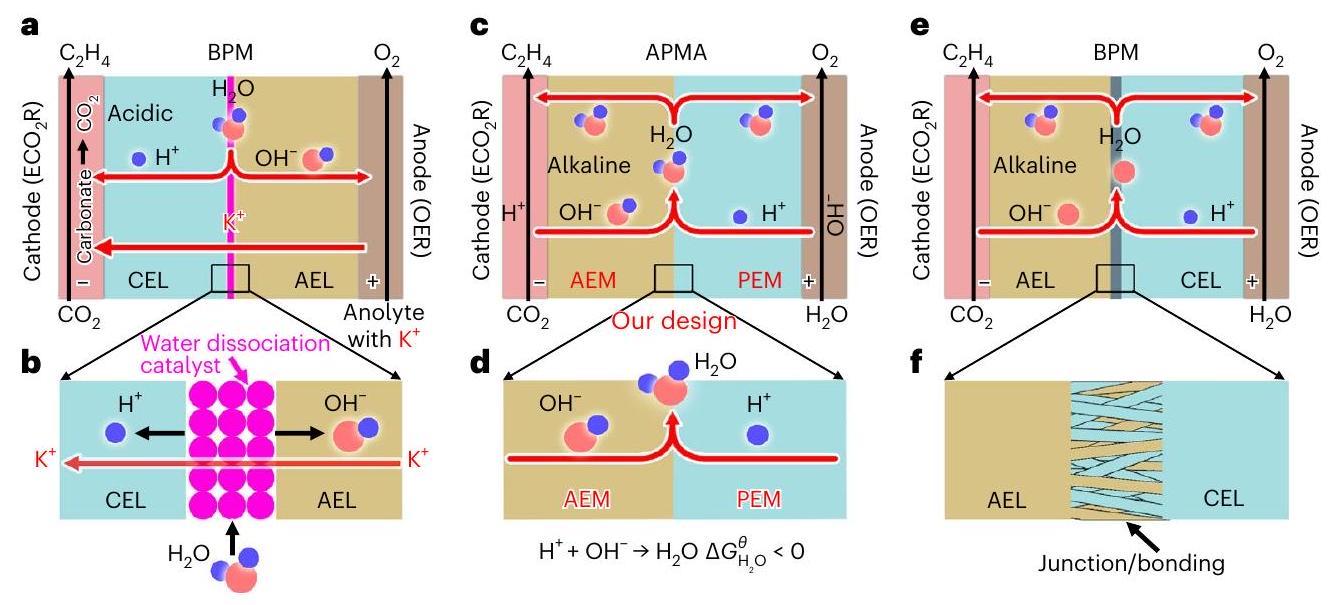
الشكل 1 | مقارنة بين أنظمة التحليل الكهربائي المختلفة لـ. أ، ب، نظام BPM (أ) والتفاعل (ب) في بيئة كاثودية حمضية في وضع الانحياز العكسي. ج، د، نظام APMA (ج) والتفاعل (د) في بيئة كاثودية قلوية
البيئة في وضع الانحياز الأمامي. النظام التجاري BPM (e) والتفاعل (f) مع وصلة ثنائية القطب/الربط عند واجهة AEL/CEL في وضع الانحياز الأمامي. إدخالللتفاعل مع الناتج الكهربائيلإنتاج كربونات (الملاحظة التكميلية 1 والشكل التكميلية 1). يمكن أن تنتشر الكاتيونات القلوية عبر غشاء تبادل الأنيونات (AEM) إلى مستوى هيلمهولتز الخارجي للقطب السالب، والأنيونات (على سبيل المثال، ، و) يمكن نقله إلى الأنود لإطلاق ويتم إعادة أكسدته إلى (المراجع. والشكل التوضيحي التكميلي 1). هذه العملية لا تؤدي فقط إلى وخسائر المنتجات ولكن أيضًا تزيد تدريجيًا من جهد الخلية وقد تستهلك حتىمدخلات الطاقة لـإلى (مرجع 15، 16). وبالتالي، حتى الآن، استقرار النظام لـإلىفي خلايا التدفق وMEA كانت عمومًا أقل من 200 ساعة (الشكل التوضيحي 2 والجدول التوضيحي 1).
في هذه المقالة، نصف تصميم نظام MEA لتجميع AEM + غشاء تبادل البروتون (PEM) (APMA) مع نقاءكمحلول أنوليتي لتقليل/منع تكوين/ترسيب الكربونات. تتفاعل AEM مع الكاثود في نظام APMA لتوفير بيئة قلوية للكاثود من أجل. يمكن أن تمنع غشاء تبادل البروتونات المقدم عند تلامسه مع الأنود بشكل فعال عبور جميع الأنيونات. والأهم من ذلك، فإن تكوين الغشاء والأنوليت يثبط التفاعلمع الناتج الكهربائيلتشكيل ترسيب الكربونات والملح. استخدمنا غشاء تبادل الأنيونات (AEM) وغشاء تبادل البروتونات (PEM) المتاح تجارياً لبناء النقي--fed (خالي من الكاتيونات القلوية) بنية APMA-MEA، التي تم تجميعها مع غنية بالخطوات السطحية عالية الأداءلـإلىأظهرت طيف رامان في الموقع وتجارب وسم النظائر أن تكوين الكربونات يمكن أن يتم قمعه بشكل فعال في النقاء-نظام APMA المعتمد بدلاً من إعادة التوليدمن كربونات. نتيجة لقمع تكوين/ترسيب الكربونات وتداخل الأنيونات،إلىيمكن أن تعمل بشكل مستمر لأكثر منبدونأو فقدان الإلكتروليتات في حالة نقية--تغذية ستة خلايا APMA-MEA بينما تحقق-خاص FE منفي الساعة 10 صباحًا.
تصميم نظام APMA
حاليًا، يمكن لاستخدام أنظمة غشاء تبادل البروتون (PEM) والغشاء الثنائي القطب (BPM) في بيئة كاثودية حمضية القضاء على تكوين الكربونات من خلال التجديدمن الكربونات إلى حد ما (الشكل التوضيحي 1)، لكن انتشار الكاتيونات من المعادن القلوية من المحلول الأنودي تحت تأثير المجال الكهربائي يتسبب في فقدان الإلكتروليت، كما أن البيئة الحمضية للقطب السالب تؤدي أيضًا إلى انخفاض في كفاءة المنتج بسبب تفاعل تطور الهيدروجين (HER) الأكثر ملاءمة من الناحية الديناميكية الحرارية.علاوة على ذلك، يحتاج نظام BPM MEA إلى أن تكون طبقة تبادل الكاتيونات (CEL) وطبقة تبادل الأنيونات (AEL) في اتصال مع القطب السالب والقطب الموجب، على التوالي. (الشكل 1أ). تحت الجهد العكسي (الملاحظة التكميلية 1)، يحدث تفكك الماء عند واجهة CEL/AEL، معمدفوع من خلال CEL/AEL للمشاركة فيتفاعل تطور الأكسجين (OER). عادةً ما يكون محفز تفكك الماء (على سبيل المثال، أو يجب تجميعه عند واجهة CEL/AEL لتقليل جهد التفكك المائي. (الشكل 1ب). ومع ذلك، في هذا التكوين، يمكن أن يتفكك الـ BPM بسهولة، مما قد يؤدي إلى تدهور كارثي في استقرار الخلية.
على الرغم من فوائد البيئة القلوية والكاتيونات القلوية لـديناميكية الاختزال في أنظمة AEM وPEM وBPM، حيث تظهر أداءً نظاميًا أقل (انظر الملاحظة التكميلية 1 للحصول على التفاصيل). لذلك، من المرغوب بشدة القيام بـفي وسائط خالية من الكاتيونات القلوية مع الحفاظ على بيئة كاثود قلوية. وبالتالي، قمنا بتصميم نظام APMA-MEA مع نقاءكمحلول أنوليتي لتقليل/منع تكوين/ترسيب الكربونات (الشكل 1c). من المهم أن تتفاعل غشاء تبادل الأنيونات مع الكاثود في نظام APMA لتوفير بيئة قلوية للكاثود حيث يحتوي غشاء تبادل الأنيونات على وفرة من(المراجع 23، 27). على عكس نظام BPM السابق (الشكل 1أ)، لا يتضمن APMA محفز لتفكك الماء، حيث يحدث تفكك الماء عند الكاثود والأنود، ويتم إنتاج ويمكن أن يتشكل الماء بشكل عفوي عند الواجهة (تغير الطاقة الحرة القياسية لجيبس،; الشكل 1د)، ويمكن أن تمر عبر AEM/PEM إلى الكاثود/الأنود. يمكن أن يمنع PEM المدخل بشكل فعال عبور جميع الأنيونات، وAPMA و النقييمكن أن يثبط الأنوليت التفاعلمع الناتج الكهربائيلتشكيل الملح/الرواسب تحت تأثير المجال الكهروستاتيكي (انظر أدناه). من حيث المبدأ، يمكن أن تلبي BPM التجارية أيضًا متطلبات نظام APMA الخاص بنا (الشكل 1e). ومع ذلك، فإن تقنية BPM الحالية غير ناضجة، مما يجعل أدائها يتفاوت بشكل كبير. عادةً ما تحتوي BPM على طبقة الوصل/الربط عند واجهة AML/CEL (الشكل 1f). قد تؤدي تكوين الماء عند الواجهة إلى فصل الطبقات وتؤدي إلى عدم استقرار BPM بسبب صعوبة التحكم في القوة الميكانيكية للوصل/الربط. في ضوء ما سبق، تم استخدام AEM وPEM المتاحة تجاريًا لبناء نظام APMA الخاص بنا.
تركيب وخصائص محفز SS-Cu
جزيئات نانوية من SS-Cu (بمتوسط قطر) ) مع عيوب تكديس وفواصل حبيبية وفيرة تم تحضيرها بواسطة طريقة محلول سهلة (الشكل 2 أ والأشكال التكميلية 3 و 4). تعزز عيوب التكديس والفواصل الحبيبية ارتفاع نشاطكشفت صور المجهر الإلكتروني الناقل عالي الدقة (HRTEM) وصور المجهر الإلكتروني الماسح (STEM) المصححة للانحرافات في مجال الظلام الزاوي العالي (HAADF) عن وجود عيوب تكديس وفيرة تتقاطع مع بعضها البعض (الشكل 2ب والشكل التكميلي 3) وحدود حبيبية متشابكة عديدة (الشكل 2ج) في SS-Cu. علاوة على ذلك، حدود الحبوب تحتوي علىحدود الشبكة المتزامنة (حدود التوأم) وتشكل بعض الهياكل التوأمية النموذجية ذات الخمسة أضعاف (الشكل 2c، الإطار الداخلي والشكل التوضيحي 5). يمكن أن تتسبب هذه العيوب الكثيرة في التراص وحدود الحبيبات في تحفيز إجهاد شد كبير على الطبقة السطحية.. في الواقع، إجهاد شد محلي كبير يصل إلى تمت ملاحظة ذلك حول مخارج السطح لكل من الحدود المزدوجة وعيوب التراص في SS-Cu من خلال تحليل الطور الهندسي (GPA) (الشكل 2d وe والشكل التكميلي 6)، مقارنةً بذلك في شبكة Cu خالية من العيوب (الشكل التكميلي 7). علاوة على ذلك، تم تحفيز أسطح متدرجة أيضًا عند مخارج السطح للحدود المزدوجة وعيوب التراص (الشكل 2d والشكل التكميلي 6)، مما أدى إلى ظهور ذرات النحاس السطحية ذات عدد تنسيق منخفض (انظر الملاحظة التكميلية 2 لمزيد من المعلومات حول SS-Cu، بالإضافة إلى مقاطع الفيديو التكميلية 1 و2، والأشكال التكميلية 8-19 والجدول التكميلي 2).
الأداء في خلية التدفق التقليدية
بعد الحصول بنجاح على محفز SS-Cu، قمنا أولاً بتقييمهالأداء في خلية التدفق تحت الظروف القلوية التقليدية (1 م KOH). قدم SS-Cu ذروة FE قدرهانحوعند حوالي -0.58 فولت (مذكور مقابل قطب هيدروجين قابل للعكس (RHE) في جميع النصوص، ما لم يُذكر خلاف ذلك)، حيثوصلت وكفاءة الطاقة في نصف الخلية ) من كان يصل إلى (الشكل 3أ، ج والشكل التكميلي 20). مقارنةً بأفضل ما هو متاح حالياً -إلى-الأداء فيمن و منحوالي، تم تسليم SS-Cu أعلى بمرات و أوقات أقل من الإمكانية. من المثير للاهتمام، وجدنا أن كثافة التيار الجزئي ( أو أظهرت علاقة خطية قوية مع دالة إجهاد الشد وعدد التنسيق (انظر الملاحظات التكميلية 3 والأشكال التكميلية 21-35 لمزيد من التفاصيل).
لإزالة تكوين الكربونات، الترسيب والتداخل في خلية AEM خلال، قمنا أيضًا بأداء فوق SS-Cu في حمض قوي (لإعادة توليدمن الكربونات المتكونةتحت الكاثوليت الحمضي القوي مع وفرة، قدم النظام أداءً مرضيًا بالكاد-إلى-أداء (من و منمعمن عند -1.1 فولت ) في خلية تدفق تم تجميعها باستخدام PEM (الشكل 3ب، د؛ انظر الملاحظة التكميلية 4 والأشكال التكميلية 36-38 للحصول على التفاصيل). بالنظر إلى الجدوى العملية، سعينا لتشغيل في خلية PEM-MEA مع بيئة كاثودية حمضية (تمامًا كما في الشكل التوضيحي 1). المحلول الأنودي معلم يُستخدم فقط كمصدر للبروتونات ولكن أيضًا لتزويدإلى الكاثود. على الرغم من أننا لاحظنا في البداية تشكيلالمنتجات (مثل CO و ) ، أُغلِقَت بعد بضع دقائق، وأصبحت هي السائدة. الاستمرار فيمرت عبر غشاء تبادل البروتون من الأنود إلى الكاثود، مصحوبة بتسرب ملح الكربونات في قناة تدفق الخلية، مما أدى إلى انسدادنقل الكتلة (الملاحظة التكميلية 4 والشكل التكميلية 39).
الأداء في النقي--نظام APMA المدعوم
استنادًا إلى النتائج الموصوفة أعلاه، اقترحنا نموذجًا نقيًا--fed (خالي من الكاتيونات القلوية) بنية التحليل الكهربائي لـ MEA، التي تم تصميمها مع توقع أنها يمكن أن تمنع تكوين/ترسيب الكربونات
الشكل 3 | الـأداء SS-Cu في خلية التدفق معحمض قوي كالإلكتروليت.، الـ FEs تجاهالمنتجات تحت مجموعة من الجهود المطبقة تحت و تحتوي على 3 MKI كالكاثوليت و كأنوليت (ب)، على التوالي. ج، د، التيار الجزئي كثافاتتحت مجموعة من الجهود المطبقة تحت و يحتوي على 3 مولي من KI كالكاثوليت و كمحلول أنولي (د)، على التوالي. القيم هي المتوسطات، وتوضح أشرطة الخطأ الانحراف المعياري.نسخ). وعبور الأنيونات. المفهوم المركزي للـ-نظام MEA المدعوم بـيحافظ على بيئة الكاثود القلوية اللازمة للفعاليةإلى منتجات متعددة الكربون. وبالتالي، قمنا بإنشاء APMA، الذي تم تضمينه في بنية MEA تحت الضغط لمنع الفصل وضمان الاتصال المتساوي بين أقطاب انتشار الغاز (GDEs) والأغشية (الشكل 4a). يمكن أن تخلق AEM المتصلة بالكاثود بيئة قلوية للكاثود، بينما يمكن أن تتجنب PEM المواجهة للأنود عبور جميع الأنيونات، بما في ذلك منتجات الأنيونات (مثل و ).
تحت الانحياز الأمامي،يحدث الانفصال عند القطب السالب والقطب الموجب، مما يشارك في وموارد التعليم المفتوحة (الشكل 1c). المتبقي عند الكاثود ويمكن نقلها عند الأنود عبر AEM و PEM، على التوالي، لتشكيل عند واجهتهم (المعادلات (1)-(3))، التي يمكن أن تمر عبر AEM/PEM إلى الكاثود/الأنود لتعيد المشاركة في أو تصريف من قناة التدفق.
الأهم من ذلك، في هيكل نظام APMA-MEA هذا، فإن احتمال أن يكون المتفاعلسيتفاعل مع الناتج الكهربائيلتشكيل ترسبات الملح (مثل ) يتم تقليله بشكل كبير (الشكل التكميلي 40). التفسير الديناميكي الحراري هو أن النقي يمكن للنظام أن يقمع بشكل فعال تكوين أملاح (بيكربونات) بينما يحدث ترسيب الأملاح (مثل أو يمكن الوقاية منه تمامًا بسبب غياب الكاتيونات تحت تأثير المجال الكهروستاتيكي. علاوة على ذلك، على الرغم من وجود كمية صغيرة منيمكن أن يذوب فيلتشكيل (المعادلة (4))، الكاثود القلوي البيئة والنقاءيمكن أن يثبط الأنوليتالتكوين. النقي-نظام APMA-MEA المعتمد على التغذية يمنع/يقلل من تكوين/ترسيب الكربونات وتداخل الأنيونات.
ومع ذلك، النقينظام التحليل الكهربائي لا يمكنه تجنب جهد التشغيل العالي. من أجل هذا النقي-نظام APMA-MEA المدعوم، يمكن تفكيك جهد الخلية بشكل مفاهيمي إلى ما يلي (المعادلة (5)) (لتبسيط الحساب، نأخذ إلىكمثال دون النظر إلى المنتجات الأخرى؛ انظر الملاحظة التكميلية 5 للحصول على التفاصيل): الإمكانات الديناميكية الحرارية لـإلىفي البيئة القلوية و OER في; الـ -إلى- وفرق الجهد في تفاعلات الأكسدة والاختزال عند كثافة تيار معينة ( و ); الجهد الديناميكي الحر لـ تشكيل (في الظروف القياسية بسبب البيئات الحمضية والقلوية عند واجهة APMA)؛ الجهد الزائد لـتشكيل ); فقدان الجهد من المقاومة الأومية ( ); فقدان الجهد من جهد نيرنست ( في درجة حرارة الغرفة). هنا، و تعرف بأنها إيجابية. حيث أن أول أكسيد الكربون هو وسيط حاسم لـالتكوين والجهد الحراري الديناميكي لـ إلى CO أكثر سلبية من ذلك لـ إلى (المراجع 7، 33-35)، تم حسابه أيضًا (الملاحظة التكميلية 5).
أين و هي ثابت الغاز المثالي، ودرجة الحرارة، وشحنة الأيون، على التوالي. عند درجة حرارة الغرفة ( المقاومة الأومية للمواد النقية-كان مستوى خلايا APMA-MEA المعتمدة على التغذية منخفضًا جدًا ( ) (الشكل 4ب). ومع ذلك، عندما تكون كثافة التيار عالية، لا يمكن تجاهله (على سبيل المثال، في ). بالإضافة إلى
الشكل 4 | تنفيذ نموذج أولي للـ-نظام APMA المدعوم بـ على SS-Cu. أ، مخطط لنظام APMA-MEA المعماري لـ مقاومة النظام عند درجات حرارة تفاعل مختلفة. ج، الطاقة الحرة للمنتجات الغازية والفولتية المقابلة للنظام عند كثافة تيار إجمالية منلدرجات حرارة تفاعل مختلفة. د، تحليل منتج الغاز الأنودي النقي--نظام APMA المدعوم بـ بكثافة تيار إجمالية قدرها . تم رش ألياف تي فيبرتم استخدامه كقطب أنودي، ومعدل التدفق لـكان المدخل 30 سم³/دقيقة. طيف رامان في الموقع لـعلى SS-Cu في 0.1 م كOH، نقيوالإلكترود العاري بعد. طيف الكتلة لـيستخدمكأنوليت في نظام APMA. ج، الجهد الزائد الكلي لجميع التفاعلات عند درجات حرارة تفاعل مختلفة. القيم هي المتوسطات، وأشرطة الخطأ تشير إلى الانحراف المعياري.تكرارات)، باستثناءحيث القيم هي المتوسطات وأشرطة الخطأ تشير إلى تأثير الرقم الهيدروجيني للغشاء الأيوني القابل للتبادل على الجهد الزائد (مع ضبط الرقم الهيدروجيني للغشاء في نطاق 8-14). النقي-يمكن تبسيط معادلة نيرنست إلى المعادلة (6) عند درجة حرارة الغرفة. (الملاحظة التكميلية 5). درجة حموضة الأنوليت هي بسبب استخدام النقي. نفترض أن الـكانت التركيزات على سطح AEM 1 م (أي، pH 14)، حيث كان انخفاض الجهد ( ) من النقي-كان جهد خلية APMA-MEA المعتمدة على التغذية حوالي 0.41 فولت. لذلك، دون النظر في الفائض الكهربائي ( و ) أو الجهد الخلوي النظري لدينا النقي--نظام APMA-MEA المدعوم بـإلىيجب أن يكون أكثر سلبية من -1.56 فولت في الظروف القياسية. بالإضافة إلى ذلك، عند النظر في الوسيط الرئيسي (CO) لـتشكيلالجهد الخلوي النظري سيكون حتى -1.74 فولت.
تشير النتائج المذكورة أعلاه إلى أن جهد التشغيل للـيجب خفض نظام APMA-MEA المدعوم لتحقيق تحويل فعال للطاقة. بعبارة أخرى، فإن الفائض الكهربائي لجميع التفاعلات، بما في ذلكيجب تقليل تكوين OER والماء. في الواقع، عندما زادت درجة حرارة التفاعلعلى SS-Cu في النقي--نظام APMA-MEA المدعوم من درجة حرارة الغرفة ( ) إلى (الشكل 4ج)، انخفض جهد الخلية من إلى 4.20 فولت عند. في الوقت نفسه، تم تقليل مقاومة الخلية بواسطة في (الشكل 4ب)، مما يعني انخفاض في الجهد .
ومع ذلك، فإن انخفاض جهد الخليةكان أكثر بكثير من، مما يشير إلى أن زيادة درجة حرارة التفاعل تقلل بشكل رئيسي من الفائض الكهربائي. إن الكفاءات المثلى لـتحققت في، حيث أن العوامل الاقتصادية للمنتجات الغازية الكربونية وكانوالـلـ و لـ ) و (الشكل 4ج)، على التوالي. ومع ذلك، عندما تم زيادة درجة حرارة التفاعل إلى ، الـ FE منكان حتى انتهىمما يشير إلى أن درجات الحرارة المرتفعة ستقمعواجعلها هي المسيطرة. وبالتالي، فإن ما يليتم إجراء اختبارات في.
علاوة على ذلك، فإن حركيات التفاعل للمواد النقية--نظام APMA-MEA المدعوم بـتم قياسه. الجهد الزائد الكلي ( ) عند كثافة تيار معينة، بما في ذلك تم تقييم OER وتكوين الماء عند درجات حرارة مختلفة باستخدام معادلات جيبس-هيلمهولتز ونيرست.محدد في الملاحظة التكميلية 5). نظرًا لعدم توفر بيانات pH للغشاء الأيوني التجاري، نفترض أن pH للغشاء الأيوني يكون في نطاق 8-14. أخذًا في الاعتبار ECOكمثال دون النظر إلى منتجات أخرى،انخفض مع زيادة درجة حرارة التفاعل (الشكل 4 ج). و إجمالي الجهد الزائد ( ) من النظام كان . بالنظر إلى الوسيط الرئيسي (CO)، كان فقط
الشكل 5| الإجماليأداء النظام لـ SS – Cu في النقاء--مغذى خلية APMA-MEA / مجموعة الخلايا. أ، العناصر الكهربائية نحوالمنتجات تحت مجموعة من كثافات التيار المطبقة، والجهود الخلوية المقابلة دونتعويض. ب، الـ FEs تجاهالمنتجات تحت مجموعة من جهود الخلايا المطبقة دون التعويض، وكثافة التيار الكلي المقابلة. ج، د، مقارنات بين كفاءات التحويل (ج) وكثافات التيار الجزئي (د) تجاه في النقاء--تم تغذية أنظمة APMA-MEA و AEM-MEA بـ 1 م KOH كأنوليت. e، مخطط لخلية APMA-MEA المكونة من ست خلايا APMA-MEA لـ
الرد فعل.أداء استقرار النظامعلى SS-Cu في حالة نقية--خلايا APMA-MEA المكدسة التي تغذيها APMA-MEA تحتوي على ستة خلايا APMA-MEA عند تيار ثابت قدره 10 أمبير. كانت مساحة كل قطب كاثود، وكانت درجة حرارة التفاعل تم استخدامه كقطب أنودي، ومعدل التدفق لـكان تدفق المدخل 30 SCCM للخلايا الفردية أو مجموعة الخلايا. تم استخدام أغشية AEM وPEM كأغشية مولدة للكهرباء.وأغشية تبادل الأيونات، على التوالي. القيم هي المتوسطات، وتوضح أشرطة الخطأ الانحراف المعياري.نسخ). عند (الشكل 4 ج). على الرغم من استخدام النقيكأنوليت، لا يزال نظام APMA-MEA يظهر القدرة على الفعاليةإلى.
النقي-تم تقييم نظام APMA-MEA المعتمد على التغذية بشكل أكبر من حيث موثوقيته في منع تكوين/ترسيب الكربونات وتداخل الأنيونات. أظهرت مطيافية الكتلة المتصلة بالتحفيز بالحث أنه لم يكن هناك تقريبًا أي كاتيونات موجودة في النقاء.الأنوليت (الشكل التكميلي 41)، باستثناءعلى مستوى جزء في المليار، originating من مصدر المياه. ثم، قمنا باختبار تركيبات المنتجات الأنودية. كما هو متوقع، فقطمن OER كان موجودًا في منتج الأنود بدونفقدان (الشكل 4d والشكل التكميلي 42). لم يحتوي المحلول الأنودي على الأنواع المحايدة الأخرى (مثل HCOOH و ) من الكاثود (الشكل التوضيحي التكميلي 42). بالإضافة إلى ذلك، أظهرت قياسات رامان في الموقع مباشرة أن تكوين الكربونات تم قمعه بشكل فعال (الذروة عند ) على سطح SS-Cu GDE في نقائنا – نظام APMA المدعوم، مقارنةً بالنظام القلوي الكهربائي (الشكل 4e والأشكال التكميلية 43-45).
علاوة على ذلك، للتحقق من أن نظام APMA يمكنه قمع تكوين الكربونات، بدلاً من تجديدهابواسطةمن تفاعل الأنوليت مع الكربونات، قمنا أيضًا بإجراء تجربة وسم النظائر (باستخدامكأنوليت). إذايمكن أن يتفاعل مع الناتج الكهربائيإلى كربونات، سيكون أحد الأكسجينات في الكربونات (المعادلة (7)). وبالتالي، تم تجديد يمكن تصنيف هذه الكربونات بـ. ومع ذلك، فإن شدة تغيرت بالكاد طوال العملية بأكملها عندما كان نظام APMA يعمل وبعد الإيقاف (الشكل 4f)، مما يشير إلى أنلم يتفاعل مع الناتج الكهربائيإلى كربونات. بدلاً من ذلك، كميات ضئيلة منيأتي من المتفاعل الأوليلأنلم تتغير الشدة خلال أو بعد. تشير هذه النتائج إلى أنه، تحت الانحياز الأمامي، النقي-يمكن لتكوين نظام APMA-MEA المدعوم أن يمنع بشكل فعال تكوين/ترسيب الكربونات وتداخل الأنيونات.
قمنا بفحصتوزيع المنتج لـ SS – Cu في النقي--نظام APMA-MEA المدعوم بـ، تحت وضع الجلفانستاتي (الشكل 5أ). عندذروة FE لـوصلت المنتجاتبما في ذلك FE نحو لـلـ، لـ و لـ ). كانت جهد الخلية بدون ( الحالي؛، تعويض المقاومة. دون احتساب الطاقة المستهلكة من درجة حرارة التفاعل، النقي-نظام APMA-MEA المدعوم بالكامل قدم كفاءة طاقة خلوية كاملة ( ) من لـ. ذروة FEs وكثافات التيار الجزئي للمنتجات في الحالة النقية – كان نظام APMA-MEA الذي يعمل بالوقود قابلاً للمقارنة مع تلك الموجودة في خلية AEM-MEA مع 1 م كوه كأنوليت (الشكل 5 أ-د والشكل التوضيحي 46). علاوة على ذلك، كانت ميزانية الكربون في النظام عندتم تقييمه أيضًا باستخدام طريقة سابقة. كل الـتم استرداد المنتجات إلى (الشكل التوضيحي 47). مجموع الـمعدل التدفق ( ) بما في ذلك استعيدت كمنتجات وغير متفاعلةقريب من البدايةمعدل التدفق (30 SCCM). يمكن أن يُعزى الاختلاف الطفيف إلى كمية صغيرة من بقايا المنتج أو التسرب. تشير تقييمات توازن الكربون إلى أن نظام APMA-MEA لدينا لا يحتوي تقريبًا علىخسارة.
عملية النقاء--خلايا APMA-MEA المدعومة بـ
مدفوعًا بالتفوقالأداء الذي أظهره SS-Cuin في النقاء-نظام APMA-MEA المدعوم، قمنا بتصميم وتخصيص مجموعة خلايا تحتوي على ست خلايا MEA لتقييم المتانة والعملية للـ-هيكل APMA-MEA المدعوم (الشكل 5e والشكل التكميلي 48). يمكن أن تمهد هذه العملية لتكبير الحجم وقياسات الاستقرار لخلية APMA-MEA الطريق لـإلىنحو تشغيل على نطاق صناعي. عند تيار إجمالي قدره 10 أمبير، تعطي ستة أقطاب كهربائية من SS-Cu FE قدرهنحو (الشكل 5f). ظل النظام مستقرًا لأكثر من مع جهد كامل للخلية بين 25 و 27 فولت دونتعويض (جهد خلية قدرهلكل مجموعة من خلايا MEA؛ الشكل التوضيحي التكميلي 49). على النقيض الشديد، فإن استقرار النظام لـعلى SS-Cu في خلية AEM-MEA مع 1 م KOH كأنوليت كانت أقل من 4 ساعات، مع وجود إلكتروليت شديد والخسائر (الشكل التوضيحي التكميلي 50). قمع/منع تكوين/ترسيب الكربونات باستخدام النقي-نظام APMA المدعوم بالتغذية بالتأكيد عزز من متانة النظام، لكن القوة الميكانيكية العالية لـ APMA نفسها والاختراق الممتاز للماء للغشاء الكهربائي التجاري AEM و PEM (Sustainion X37-50 و Nafion 117) لـ APMA كانت أيضًا مواتية لتحسين استقرار النظام عند كثافة تيار غير متطرفة.-إلى- كانت نسبة التحويل في مجموعة خلايا 6-APMA-MEA الخالية من الكاتيونات القلوية تصل إلى . بعد لم يتم ملاحظة أي فيضان لـ GDE خلال فترة التشغيل، وهو ما يمكن أن يُعزى إلى ارتفاع درجة حرارة التفاعل.يسمحتراكمت في GDEs ليتم تفريغها بسرعة مع البخار.
في هذا النقي-نظام كومة APMA-MEA المدعوم بالطاقة، قمنا أيضًا بتطوير دائرة متكاملة تعتمد على لوحة تطوير Arduino لمراقبةالعملية (الشكل التكميلي 49، الإطار). وبناءً عليه، أظهرت كل خلية جهدًا متطابقًا طوال القياس، باستثناء بعض التقلبات خلال الساعات المئة الأولى (الشكل التكميلي 49)، مما يوضح إمكانيات مجموعة APMA-MEA لتحقيق استقرار عالٍ إلى، كما هو مطلوب للتشغيل الصناعي. الأداء العام للنظام إلىعلى SS-Cu في نقائنا-نظام APMA-MEA المعتمد على التغذية هو تنافسي للغاية مع التقارير السابقة (الشكل التكميلي 2 والجدول التكميلي 1). تحسينات الأداء العامة للنظامإلىفي النقاء-يمكن أن يُعزى أداء نظام APMA-MEA المعتمد على التغذية إلى مزيج من بنية التحليل الكهربائي لـ APMA والنشاط التحفيزي المتفوق لـ SS-Cu.
تظهر قياسات حيود الأشعة السينية في الموقع (XRD) أن التركيب البلوري لـ SS-Cu مستقر خلال عند فولتية خلايا مختلفة (الأشكال التكميلية 51-53). علاوة على ذلك، تظهر صور STEM في مجال الضوء الساطع الحلقي (ABF-STEM) وTEM وHRTEM أن محفز SS-Cu احتفظ بسلامته الهيكلية طوال الفترة الطويلة العملية (الشكل التوضيحي التكميلي 54). يمكن الحكم على ذلك من وجود عيوب التراص المحللة ذريًا وحدود الحبيبات (حدود التوأم) في صور HAADF-STEM قبل وبعد فترة طويلة من (الشكل التوضيحي 54).
تحقيق فيتشكيل
المتوسطات الرئيسية لـتركيب لـتكوين علىتمت دراستها بواسطة مطيافية رامان في الموقع، وتجارب اختزال CO الكهروكيميائية، وحسابات نظرية الكثافة الوظيفية (DFT) (انظر الملاحظات التكميلية 6 والأشكال التكميلية 55-59 للحصول على التفاصيل). كشفت قياسات رامان في الموقع عن وجود الوسط *CO ورابطة C-H، بينما استبعدت تجارب ECOR تفاعل ثنائي *CO لـالتكوين. من خلال مقارنة طاقة التفاعل للوسطاء التفاعليين المحتملين (مثلثنائي ) ، المواتية اقتران بـقد يكون التكوين على SS-Cu هو أن *CO و *CHO يتزاوجان لتكوين *COCHO بسبب انخفاض طاقة التفاعل. الآلية مشابهة للتيار الرئيسي.إلىالآلية المبلغ عنها سابقًامما يعني أن الأداء الفعال للغاية لا يمكن أن يُعزى إلى مسار تفاعل جديد تم اكتشافه، بل إلى التنظيم الناجح لانتشار الأيونات والكتلة وكبح التفاعلات الجانبية في نظام APMA-MEA.
الاستنتاجات
نحن نثبت أن النقي-نظام APMA-MEA الخالي من الكاتيونات القلوية يمكن أن يثبط/يمنع بشكل فعال تكوين/ترسيب الكربونات وتداخل الأنيونات أثناءبينما يتجنب الأعباء الثقيلة لـ HER وكذلكوخسائر الإلكتروليت. إن بساطة تصميم النظام تحسن الأداء العام للنظام من أجلمن خلال الحفاظ على بيئة كاثود قلوية دون تزويد أيونات القلوي. تكشف التجارب الواسعة أن النقي-نظام APMA المعتمد على التغذية يمكن أن يثبط/يمنع بشكل فعال تكوين/ترسيب الكربونات بدلاً من تجديدها.من كربونات. عند مستوى صناعي حالي، فإن الاستقرار العام للنظام الذي تم توسيعهإلىعلى SS-Cu يتم تعزيزها بشكل كبير في النقي--خلايا AMPA-MEA المكدسة التي تعمل بالطاقة. ومع ذلك، على الرغم من أن نظامنا أظهر أداءً تنافسياً للنظام من أجلإلىلا يزال من الضروري تحسين انتقائية المنتج بشكل أكبر وتقليل جهد التشغيل من أجل تحقيق تحويل طاقة فعال.
طرق
المواد الكيميائية
أكسيد الديوتيريوم (99.9 at.% د؛ 151882)، 3-(تريميثيل سيليل) بروبيونيك-2,2,3,3-ملح الصوديوم الحمضي (TSP، (NMR)؛ 269913)، محلول نافيون (5 وزني.٪؛ 274704)، تحضير بولي تترافلوروإيثيلين (حل في; 665800)، أوليامين (كلوريد النحاس (I) ) ، -الهكسان (; HX0293)، أوكتاديسيل أمين (“; 305391)، ثلاثي أوكتيل الفوسفين (; 117854)، سكوالان (; 234311)، هيدروكسيد البوتاسيوم (KOH، 99.99٪؛ 306568)، حمض الفوسفوريك ( ) ، نترات البوتاسيوم ( ; 221295)، نترات الرصاص (II) (; 228621)، يوديد البوتاسيوم (KI، 99٪؛ 221945)، ماء- وكلوريد البوتاسيوم ( ; تم شراء P3911) من سيغما ألدريتش. هيدروكسيد البوتاسيوم ( )، رغوة النيكل (سمك 2 مم، 99.9%) وألياف التيتانيوم (سمك 0.25 مم، 99.9%) تم شراؤها من شركة سينوفارم للمواد الكيميائية المحدودة (الصين). حمض النيتريك ( ; 200 ) و أيزوبروبانول ( IPA,; 3776) تم شراؤها من فيشر ساينتيفيك. تم شراء AEM (Fumasep FAA-3-PK-75) وطبقة انتشار الغاز (ورق الكربون، GDE؛ Sigracet 39 BB) وغشاء Nafion 117 (591239) من FuelCellStore. تم شراء محلول الأيونومر القلوي (5% في الإيثانول، Sustainion XA-9) وAEM (Sustainion X37-50) من Dioxide Materials.
تحضير المواد والأقطاب
في تخليق نموذجي، تم إذابة 0.05 جرام من CuCl و 0.1 جرام من أوكتاديسيل أمين في 1 مل من سكوالين عندتحت جو الأرجون وتم الاحتفاظ به عند هذه الدرجة الحرارة لمدة 0.5 ساعة لتكوين محلول أساسي قائم على النحاس.
بعد ذلك، تم إضافة 10 مل من أوليامين و0.5 مل من ثلاثي أوكتيل الفوسفين إلى دورق وتسخينها إلىتحت جو الأرجون مع اهتزاز مغناطيسي شديد. ثم، تم حقن محلول المخزون القائم على النحاس بسرعة في حواليمحلول أوليلامين وتم الاحتفاظ به عند هذه الدرجة الحرارة لمدة 5 ساعات. بعد التبريد الطبيعي، تم جمع العينة الناتجة عن طريق الطرد المركزي وغسلها عدة مرات بـ-الهكسان. أخيرًا، تم تجفيف العينة بالهواء باستخدام غاز الأرجون في درجة حرارة الغرفة. وتمت الإشارة إلى العينة باسم SS-Cu.
تمت معالجة عينات SS-Cu عند درجات حرارة مختلفة (250، 350 و; و ) في فرن أنبوبي لمدة ساعتين تحت غاز مختلط ( ) لمنع الأكسدة. بالإضافة إلى ذلك، تم تحضير النحاس المستخرج من الأكسيد عن طريق التكلس المباشر لـ SS-Cu عند في الهواء لمدة ساعتين.
تم إجراء قياسات خلية التدفق وخلية MEA تحت الظروف القلوية على النحو التالي: تم تحضير GDEs الكاثودية على ورق الكربون التقليدي. تم توزيع المحفز في محلول مختلط يحتوي على وكحول الأيزوبروبيل (IPA) ( )، وبعض محلول الأيونومر القلوي (5 وزن.% مقابل المحفز، Sustainion XA-9) عن طريق الصوتنة لمدة ساعة لتشكيل حبر المحفز. تم تصنيع GDEs عن طريق رش الحبر على ورق الكربون مع طبقة نفاذية غازية كربونية ميكرو مسامية بتحميل قدره، تليها التجفيف في في الفراغ لمدة ساعة واحدة قبل الاستخدام (SS-Cu GDE). كانت القطب الأنودي مزيجًا من و ورق كربون مدعوم.
تم إجراء قياسات خلية التدفق وخلية MEA تحت الظروف الحمضية على النحو التالي: تم استبدال الأيونومر القلوي بمحلول نافيون. تم رش محلول بوليميثيل ميثاكريلات الذي يحتوي على محلول بولي تترافلورو إيثيلين على GDE SS-Cu كـ GDE الكاثود (SS-Cu/بوليميثيل ميثاكريلات). تم خلط ألياف التيتانيوم المدعومة بالبلاتين. ) تم استخدامه كقطب أنود. تم ترسيب البلاتين على ألياف التيتانيوم باستخدام هدف بلاتيني نقي في بيئة الأرجون ( توري) في نظام ترسيب المغناطيس.
لقياسات MEA تحت النقاءتم استخدام SS-Cu GDE و Pt/Ti GDE مباشرة كأقطاب كاثود وأنود، على التوالي.
الكهربائية التحفيزيةتقليل
تم إجراء اختبارات كيميائية كهربائية في خلايا التدفق وMEA باستخدام محطة عمل كيميائية كهربائية (CHI 660E) متصلة بمعزز تيار (CHI 680C)، باستثناء مجموعة خلايا MEA. تم استخدام جهاز تحكم تدفق الكتلة (Alicat Scientific MC) للتحكم فيمعدل التدفق. كان معدل تدفق تيار الإلكتروليت، يتم التحكم فيه بواسطة مضخة بيرستالتية ما لم يُذكر خلاف ذلك. كانت منطقة الكاثود في خلية التدفق وMEA هيما لم يُذكر خلاف ذلك. جميعتمت القياسات في درجة حرارة الغرفة ما لم يُذكر خلاف ذلك. بالنسبة لجميع قياسات خلية التدفق،تم استخدام (إلكترود الكالوميل المشبع، KCl المشبع) كإلكترود مرجعي، وجميع إمكانيات الكاثود (مقابلتم تحويلها إلى مقياس RHE باستخدام المعادلة
أينهو المقاومة بين الكاثود وأقطاب المرجع التي تم قياسها بواسطة طيف الامتياز الكهروكيميائي في نطاق التردد منإلى 0.01 هرتز عند جهد الدائرة المفتوحة. بالنسبة لجميع قياسات MEA، يتم تقديم جهد الخلية الكامل مباشرة دونتعويض
تحت الظروف القلوية، تم استخدام 1 م كOH كإلكتروليت لقياسات خلية التدفق، وتم استخدام AEM (Fumasep FAA-3-PK-75) لفصل حجرة الكاثوليت وحجرة الأنوليت.تم تزويد الكاثود بمعدل تدفق قدره 30 سم مكعب في الدقيقة.في خلية MEA تحت ظروف قلوية، تم استخدام 1 م كOH كأنوليت، وكانت أقطاب الكاثود والأنود GDEs مفصولة بواسطة AEM (Sustainion X37-50).
تحت الظروف الحمضية، لقياسات خلية التدفق، 1 ممعتم استخدامه ككاثوليت، وكان استخدم كأنوليت. كانت غرف الكاثود والأنود مفصولة بنفايون 117. لقياسات MEA،معتم استخدامه كأنوليت.تم تزويد الكاثود بمعدل تدفق قدره 30 سم³/دقيقة.
لقياسات مكدس APMA-MEA على نطاق واسع، تم استخدام دائرة متكاملة تعتمد على لوحة تطوير Arduino (UNO R3، A000066) كنظام مراقبة مساعد متصل بأداة تطبيق الطرفية التسلسلية CoolTerm. جميع ECOتم إجراء قياسات R في مجموعة APMA-MEA باستخدام مصدر طاقة مستمر متنوع مخصص.معدلات تدفق الأنوليت وكانواو 30 سم مكعب في الدقيقة، على التوالي. كانت درجة حرارة التفاعل. بالنسبة لنظام APMA، قبل التجميع، تم تنظيف AEM باستخدام نقاءلإزالة أيونات أخرى حيث تم غمر AEM في 1 م كوه مسبقًا. تم نقع PEM التجاري فيبيروكسيد الهيدروجين لمدة ساعة واحدة عندماء منزوع الأيونات لمدة ساعة واحدة عند و لمدة ساعة أخرى عند. تم تنظيف الـ PEM الناتج باستخدام النقيومحفوظ في ماء منزوع الأيونات عند درجة حرارة الغرفة.
تحليل المنتج
للتفاعل الكهروكيميائيوتقليل CO، تم قياس المنتجات الغازية والسائلة بواسطة كروماتوغرافيا الغاز (GC، GC-2030؛ شيمادزو) وطيف الرنين المغناطيسي النووي (NMR، ECZ500R، 500 ميغاهرتز؛ جيول). كانت جهاز GC مزودًا بكاشفين للموصلية الحرارية لـ و إشارات وكاشف تأين اللهب لـ و الإشارات. تم إجراء الكروماتوغرافيا الغازية باستخدام أعمدة محشوة من نوعين من Porapak-N، ومصفاة جزيئية-13X، ومصفاة جزيئية-5A، وPorapak-Q وعمود HP-PLOT AL/S، باستخدام و كغازات حاملة. لمعايرةمعدل التدفق عند مخرج الخلية ( )، تم تغذية المادة المستخدمة كمعيار داخلي بمعدل 10 SCCM وخلطها مع تيار الغاز الخارج من الخلية قبل الحقن من أجل تم حساب FEs لمنتجات الغاز باستخدام المعادلة
أين هو عدد الإلكترونات المنقولة للمنتج هو الثابت فاراداي، هو الكسر المولي للمنتجمحدد بواسطةهو معدل تدفق المول و هو كثافة التيار الكلي.
تم تحليل المنتجات السائلة بواسطةطيف الرنين المغناطيسي النووي (ECZ500R؛ JEOL) مع تقليل الماء. TSP وتم استخدامهما كمعيار مرجعي ومذيب قفل، على التوالي. تم حساب كفاءات المنتجات السائلة باستخدام المعادلة
أينهو عدد الإلكترونات المنقولة للمنتج السائل، هو الثابت فاراداي، هو تركيز المنتج السائلمحدد بواسطة هو حجم الإلكتروليت و هو الشحن الكلي.
كفاءة الطاقة للخلايا نصفية والخلايا كاملة و ) تم حسابها باستخدام المعادلات التالية (معتبرين OER كمثال لتفاعل الأنود ويفترض أنه يحدث مع جهد زائد من مقابل RHE):
أين و هي الإمكانيات الديناميكية الحرارية (مقابل RHE) لتفاعل الأكسدة الكهربائية للأكسجين (OER) و إلى منتجعلى التوالي،هو FE للمنتج هو الجهد المطبق عند الكاثود و هو جهد الخلية لنظام MEA.
التم حساب التحويل باستخدام المعادلات
أينهو معدل التكوين المولي للمنتجهو وقت تفاعل التحليل الكهربائي وهو المساحة الهندسية للقطب الكهربائي.
قياسات رامان الكهروكيميائية في الموقع
تم إجراء قياسات رامان في الموقع باستخدام خلية تدفق كهربائية طيفية مخصصة مصنوعة من نافذة ياقوتية.أمام الكاثود GDE. تم استخدام النيكل ككهرباء مضادة. تم تشغيل النظام الكلي في إعداد ذو قطبين. تم ضخ الإلكتروليت (0.1 M KOH) في نافذة من الياقوت بمعدل تدفق ثابت منباستخدام مضخة بيرستالتية فوق الكاثود GDE، وكان سمك مستوى الإلكتروليت على سطح الكاثودتم تزويدها إلى الجزء الخلفي من GDE الكاثودي من خلال قناة تدفق متعرجة لتوجيهبمعدل تدفق قدره 30 SCCM، يتم التحكم فيه بواسطة جهاز التحكم في تدفق الكتلة (Alicat Scientific MC). تم جمع طيف رامان باستخدام وقت تجميع قدره 4 ثوانٍ وعدد تجميع عشرة مرات باستخدام ميكروسكوب رامان التداخلي WITEC معتم تطبيق جهد الخلية في وضع الجهد الثابت وتم تسجيله دونتعويض
قياسات الأشعة السينية الكهروكيميائية في الموقع
تم استخدام خلية التدفق الطيفي الكهروكيميائية المخصصة لإجراء قياسات XRD في الموقع في إعداد ذو قطبين. تم استخدام شعيرة النيكل كقطب مضاد، وتم استخدام 0.1 م من هيدروكسيد البوتاسيوم كإلكتروليت وتم تزويد الجزء الخلفي من GDE الكاثودي. تم جمع أنماط XRD في الموقع على جهاز حيود الأشعة السينية (Rigaku SmartLab 9 kW ، Advance) باستخدام Cu Kإشعاع Å) عند 45 كيلو فولت و 200 مللي أمبير. كانت مدة الاختبار الفردي حواليفينطاق منتم تطبيق جهد الخلية في وضع التحكم الجهد وتم تسجيله بدونتعويض
قياسات TEM للتسخين في الموقع
تم إجراء قياسات TEM للتسخين في الموقع على جهاز JEOL JEM-2100F عند 200 كيلوفولت باستخدام حامل Fusion Select (Protochips) ورقاقة ميكرو-إلكتروميكانيكية مغطاة بالكربون المثقوب (E-FHBC-10، Protochips).
قياسات ترسيب تحت الجهد للرصاص
تم استكشاف النسب السكانية للواجهات المكشوفة للنحاس باستخدام قياسات ترسيب الرصاص تحت الجهد في خلية ذات ثلاثة أقطاب ومقصورة واحدة. قضيب كربون جرافيتي وتم استخدامهما كالكاثود المرجعي والمرجع، على التوالي. تم استخدام إلكترود كربوني زجاجي من نوع L محمّل بالعينة بقطر 3 مم كإلكترود عمل.-مُطهَّرمعتمت الإضافة معلتعديل الرقم الهيدروجيني إلى 1، يستخدم كالإلكتروليت. الفولتمترية الدورية بمعدل سحبتم استخدامه للقياسات.
قياسات إزالة الحرارة المبرمجة
قياسات إزالة الحرارة المبرمجةتم إجراء التجارب على العينات باستخدام نظام الامتزاز/الامتزاز. في تجربة نموذجية، GDE مع حمل المحفز من تم طحنه إلى مسحوق ثم وُضع في ميكرو رياكتور كوارتز على شكل حرف U. بعد ذلك، تم توصيل مخرج ميكرو رياكتور الكوارتز على شكل حرف U بجهاز الكروماتوغرافيا الغازية (GC-2014، شيمادزو) مع كاشف الموصلية الحرارية. بعد ذلك،تم حقنها في المفاعل الميكروي المصنوع من الكوارتز على شكل حرف U واستمرت في التدفق لمدة 60 دقيقة، تلاها غسل العينة باستخدام تيار الهيليوم (40 SCCM) حتى الحصول على خط أساسي مستقر في جهاز الكروماتوغرافيا الغازية. ثم تم إجراء قياسات إزالة الحرارة المبرمجة من درجة حرارة الغرفة إلىبمعدل انحدار، باستخدام الكروماتوغرافيا الغازية للكشف عن تم إزالتها من سطح العينة.
حسابات DFT
تم إجراء جميع حسابات DFT باستخدام برنامج فيينا لمحاكاة الحالة الأولية. تم استخدام تقريب التدرج العام مع طريقة بيرد-دو-بورك-إرنزرهوف.تم اعتماد دالة التبادل والتداخل لوصف تفاعلات التبادل والتداخل الإلكترونية مع طاقة قطع تبلغ 500 إلكترون فولت. تم تعيين معايير تقارب الطاقة إلىلإجراء حسابات متسقة ذاتيًا، وتم تحسين معلمات الشبكة حتى كانت درجة تقارب القوة على كل ذرة أقل من 0.05 إلكترون فولت.مونكهورست-باكتم استخدام شبكة ذات نقاط لدمج منطقة بريلوان.
لـ Cu المثالي، تم تحسين بنية بلورة النحاس مع ثابت شبكة قدره. بالنسبة لـ Cu -SF، تم توسيع وحدة الخلية بعامل 1.1 ثم تم استرخاءها بالكامل حتى الوصول إلى التقارب. تم تحديد ثابت الشبكة ليكون 4.000 Å. ست طبقات p( خلايا عظمى منتم استخدام وجه، مع تثبيت الطبقات الثلاث السفلية. بالنسبة لجميع نماذج الألواح، كانت سماكة الفراغ في اتجاه عمودي على مستوى المحفز لا تقل عنلتجنب الجاذبية من الصور المرآوية الدورية المجاورة. في جميع الحالات الوسيطة، يتم إضافة جزيئين من الماء بالقرب من سطح اللوح للنظر في تأثير الإذابة.
طاقة غيبس الحرة ( ) من الوسائط التفاعلية تم تعريفه على أنه
أين هو الفرق الكلي في الطاقة، هو الفرق بين طاقة النقطة الصفرية و هو فرق الإنتروبيا. لاحظ أن هو نصف الـ طاقة تحت 1.013 بار فيهو طاقةتحت 0.035 بار عند 298.15 كتم تصحيح طاقة النقطة الصفرية والإنتروبيا من خلال حساب الترددات الاهتزازية باستخدام نظرية الاضطراب الوظيفي الكثافي عند 298.15 ك.
توصيف
تم جمع صور TEM على جهاز JEOL JEM-2100F عند 200 كيلو فولت. تم جمع صور HAADF-STEM المصححة للانحرافات على جهاز TFS Spectra 300 عند 300 كيلو فولت. تم إجراء تحليل GPA على الصور ذات الدقة الذرية باستخدام برنامج Digital Micrograph لاشتقاق إجهاد الشبكة. تم قياس الإجهاد العمودي فقط على عيوب التراص وحدود التوأمة، باستخدام الشبكة البعيدة عن هذه العيوب كمرجع (إجهاد صفر). تم التقاط صور المجهر الإلكتروني الماسح على جهاز Tescan MAIA3 ذو الانبعاث الميداني. تم تسجيل أنماط XRD على جهاز Rigaku SmartLab 9 kW Advance diffractometer باستخدام النحاس.إشعاعتم جمع طيف XPS على جهاز طيف الكترون الضوئي من ثيرمو فيشر نيكسا باستخدام ألومنيوم Kالإشعاع معكمصدر مرجعي. تم جمع طيف ICP-MS على جهاز Agilent 7900. تم إجراء قياسات طيف الامتصاص بالأشعة السينية الصلبة في خط الشعاع BL01C من مركز أبحاث الإشعاع المتزامن في هسينتشو، تايوان.
توفر البيانات
يعلن المؤلفون أن جميع البيانات التي تدعم نتائج هذه الدراسة متاحة ضمن الورقة وملفات المعلومات التكميلية. يتم توفير بيانات المصدر مع هذه الورقة.
References
De Luna, P. et al. What would it take for renewably powered electrosynthesis to displace petrochemical processes? Science 364, eaav3506 (2019).
Wakerley, D. et al. Gas diffusion electrodes, reactor designs and key metrics of low-temperature electrolysers. Nat. Energy 7, 130-143 (2022).
Mariano, R. G., McKelvey, K., White, H. S. & Kanan, M. W. Selective increase in electroreduction activity at grain-boundary surface terminations. Science 358, 1187-1192 (2017).
Xia, C. et al. Continuous production of pure liquid fuel solutions via electrocatalytic reduction using solid-electrolyte devices. Nat. Energy 4, 776-785 (2019).
Zhong, M. et al. Accelerated discovery of electrocatalysts using active machine learning. Nature 581, 178-183 (2020).
García de Arquer, F. P. et al. electrolysis to multicarbon products at activities greater than . Science 367, 661-666 (2020).
Morales-Guio, C. G. et al. Improved reduction activity towards alcohols on a tandem gold on copper electrocatalyst. Nat. Catal. 1, 764-771 (2018).
She, X. J., Wang, Y. F., Xu, H., Tsang, S. C. E. & Lau, S. P. Challenges and opportunities of electrocatalytic reduction to chemicals and fuels. Angew. Chem. Int. Ed. 134, e202211396 (2022).
Monteiro, M. C. O. et al. Absence of electroreduction on copper, gold and silver electrodes without metal cations in solution. Nat. Catal. 4, 654-662 (2021).
Zhang, F. & Co, A. C. Direct evidence of local pH change and the role of alkali cation during electroreduction in aqueous media. Angew. Chem. Int. Ed. 58, 1674-1681 (2019).
Huang, J. E. et al. electrolysis to multicarbon products in strong acid. Science 372, 1074-1078 (2021).
Yang, K. L. et al. Cation-driven increases of utilization in a bipolar membrane electrode assembly for electrolysis. ACS Energy Lett. 6, 4291-4298 (2021).
Endrődi, B. et al. Operando cathode activation with alkali metal cations for high current density operation of water-fed zero-gap carbon dioxide electrolysers. Nat. Energy 6, 439-448 (2021).
Liu, Z. C., Yang, H. Z., Kutz, R. & Masel, R. I. electrolysis to CO and at high selectivity, stability and efficiency using sustainion membranes. J. Electrochem. Soc. 165, J3371 (2018).
Rabinowitz, J. A. & Kanan, M. W. The future of low-temperature carbon dioxide electrolysis depends on solving one basic problem. Nat. Commun. 11, 5231 (2020).
Ozden, A. et al. Cascade electroreduction enables efficient carbonate-free production of ethylene. Joule 5, 706-719 (2021).
Siritanaratkul, B. et al. Zero-gap bipolar membrane electrolyzer for carbon dioxide reduction using acid-tolerant molecular electrocatalysts. J. Am. Chem. Soc. 144, 7551-7556 (2022).
Gu, J. et al. Modulating electric field distribution by alkali cations for electroreduction in strongly acidic medium. Nat. Catal. 5, 268-276 (2022).
O’Brien, C. P. et al. Single pass conversion exceeding in the electrosynthesis of multicarbon products via local regeneration. ACS Energy Lett. 6, 2952-2959 (2021).
Ovalle, V. J., Hsu, Y. S., Agrawal, N., Janik, M. J. & Waegele, M. M. Correlating hydration free energy and specific adsorption of alkali metal cations during electroreduction on Au. Nat. Catal. 5, 624-632 (2022).
Pribyl-Kranewitter, B., Beard, A., Schuler, T., Diklić, N. & Schmidt, T. J. Investigation and optimisation of operating conditions for low-temperature reduction to CO in a forward-bias bipolar-membrane electrolyser. J. Electrochem. Soc. 168, 043506 (2021).
Pătru, A., Binninger, T., Pribyl, B. & Schmidt, T. J. Design principles of bipolar electrochemical co-electrolysis cells for efficient reduction of carbon dioxide from gas phase at low temperature. J. Electrochem. Soc. 166, F34-F43 (2019).
Pärnamäe, R. et al. Bipolar membranes: a review on principles, latest developments, and applications. J. Membr. Sci. 617, 118538 (2021).
Oener, S. Z., Foster, M. J. & Boettcher, S. W. Accelerating water dissociation in bipolar membranes and for electrocatalysis. Science 369, 1099-1103 (2020).
Chen, L. H. K., Xu, Q. C., Oener, S. Z., Fabrizio, K. & Boettcher, S. W. Design principles for water dissociation catalysts in highperformance bipolar membranes. Nat. Commun. 13, 3846 (2022).
Xie, K. et al. Bipolar membrane electrolyzers enable high single-pass electroreduction to multicarbon products. Nat. Commun. 13, 3609 (2022).
Li, W. Z. et al. Bifunctional ionomers for efficient co-electrolysis of and pure water towards ethylene production at industrial-scale current densities. Nat. Energy 7, 835-843 (2022).
Feng, X. F., Jiang, K. L., Fan, S. S. & Kanan, M. W. Grain-boundarydependent electroreduction activity. J. Am. Chem. Soc. 137, 4606-4609 (2015).
Mariano, R. G. et al. Microstructural origin of locally enhanced electroreduction activity on gold. Nat. Mater. 20, 1000-1006 (2021).
Feng, X. F., Jiang, K. L., Fan, S. S. & Kanan, M. W. A direct grain-boundary-activity correlation for CO electroreduction on Cu nanoparticles. ACS Cent. Sci. 2, 169-174 (2016).
Huang, W. X. et al. Steam-created grain boundaries for methane C-H activation in palladium catalysts. Science 373, 1518-1523 (2021).
Yin, Z. L. et al. An alkaline polymer electrolyte electrolyzer operated with pure water. Energy Environ. Sci. 12, 2455-2462 (2019).
Nitopi, S. et al. Progress and perspectives of electrochemical reduction on copper in aqueous electrolyte. Chem. Rev. 119, 7610-7672 (2019).
She, X. J. et al. Tandem electrodes for carbon dioxide reduction into products at simultaneously high production efficiency and rate. Cell Rep. Phys. Sci. 1, 100051 (2020).
Chen, C. B. et al. Cu-Ag tandem catalysts for high-rate electrolysis toward multicarbons. Joule 4, 1688-1699 (2020).
Ramdin, M. et al. High pressure electrochemical reduction of to formic acid/formate: a comparison between bipolar membranes and cation exchange membranes. Ind. Eng. Chem. Res. 58, 1834-1847 (2019).
Kim, J. Y. T. et al. Recovering carbon losses in electrolysis using a solid electrolyte reactor. Nat. Catal. 5, 288-299 (2022).
Ma, M. et al. Insights into the carbon balance for electroreduction on Cu using gas diffusion electrode reactor designs. Energy Environ. Sci. 13, 977-985 (2020).
شكر وتقدير
نشكر مركز الإشعاع السنكروتروني الوطني، هسينتشو، تايوان، على استخدام خط الشعاع BLO1C. نشكر أردوينو على الأجهزة والبرمجيات مفتوحة المصدر. تم دعم هذا العمل ماليًا من قبل مجلس منح الأبحاث في هونغ كونغ (C5029-18E) وجامعة بوليتكنيك هونغ كونغ (1-CD7U، 1-YXAO وQ-CDAK) ومؤسسة العلوم الطبيعية الوطنية في الصين (22108109 و22178152).
مساهمات المؤلفين
أشرف S.P.L. على المشروع. قام X.S. و S.P.L. بتصور الفكرة وتصميم جميع خلايا التحليل الكهربائي وأجروا تخليق المحفزات، وتوصيفها، واختبارات التحفيز، وتحليل البيانات. قام X.S. و L.Z. بتنفيذ جميع التجارب الكهروكيميائية. قام L.Z. بإجراء محاكاة DFT. ساهم Y.W. في تحليل البيانات. قام P.X. و T.-S.W. و M.M.-J.L. بتنفيذ بيانات عدد التنسيق والضغط. قام M.C.W. و X.S. بتصميم الدائرة بناءً على Arduino وكتابة البرنامج. قام Y.Z. و Z.X. و X.G. بإجراء قياسات المجهر الإلكتروني الناقل عالي الدقة. ساعد H.L. و H.X. في تخليق المحفز. كتب X.S. الورقة. قام S.P.L. و Y.W. و S.C.E.T. بمراجعة الورقة. ناقش جميع المؤلفين النتائج وساهموا في إعداد الورقة.
المصالح المتنافسة
قدمت S.P.L. و X.S. طلب براءة اختراع أمريكي (رقم الطلب 17/806102) يتعلق بالتحفيز وهندسة MEA. يعلن المؤلفون الآخرون عدم وجود مصالح متنافسة.
قسم الفيزياء التطبيقية، معهد الأبحاث للطاقة الذكية، جامعة بوليتكنك هونغ كونغ، هونغ كونغ، جمهورية الصين الشعبية.مركز وولفسون للتحفيز، قسم الكيمياء، جامعة أكسفورد، أكسفورد، المملكة المتحدة.مركز أبحاث الإشعاع السنكروتروني الوطني، هسينتشو، تايوان.معهد أبحاث الطاقة، كلية البيئة وهندسة السلامة، جامعة جيانغسو، تشنجيانغ، جمهورية الصين الشعبية.ساهم هؤلاء المؤلفون بالتساوي: شياوجي شي، لينغ لينغ زهاي، ييفي وانغ.البريد الإلكتروني: xh@ujs.edu.cn; yezhu@polyu.edu.hk; edman.tsang@chem.ox.ac.uk; apsplau@polyu.edu.hk
Electrocatalytic reduction at near-ambient temperatures requires a complex inventory of protons, hydroxyls, carbonate ions and alkali-metal ions at the cathode and anode to be managed, necessitating the use of ion-selective membranes to regulate pH. Anion-exchange membranes provide an alkaline environment, allowing reduction at low cell voltages and suppression of hydrogen evolution while maintaining high conversion efficiencies. However, the local alkaline conditions and the presence of alkali cations lead to problematic carbonate formation and even precipitation. Here we report a pure-water-fed (alkali-cation-free) membrane-electrode-assembly system for reduction to ethylene by integrating an anion-exchange membrane and a proton-exchange membrane at the cathode and anode side, respectively, under forward bias. This system effectively suppresses carbonate formation and prevents salt precipitation. A scaled-up electrolyser stack achieved over stability without and electrolyte losses and with 50% Faradaic efficiency towards ethylene at a total current of 10 A .
Producing high-value chemicals and feedstocks from electrocatalytic reduction ( ) powered by sustainable energy could close the carbon loop and mitigate greenhouse gas emissions . Much of the research effort in this regard has focused on optimizing the product selectivity, that is, the Faradaic efficiency (FE), of the catalysts for , increasing their productivity (current density) and lowering the overpotentials of the reduction reactions . However, optimizing only the catalytic module in the system often does not translate into better overall system performance in large-scale reactors, where system stability is a major concern. The short lifespan of is partially caused by carbonate precipitation and crossover accompanied
by electrolyte loss, resulting in additional energy consumption and loss .
Currently, most systems include alkali-metal electrolytes (for example, ) (Supplementary Fig.1) because alkali-metal cations accelerate reaction kinetics, whose activity trend follows the sequence (ref. 9). However, the local alkaline cathode condition can lead to carbonate formation, while introducing alkali-metal cations can even result in salt precipitation, complicating the electrolysis system and causing unstable overall system performance. For example, in the membrane-electrode-assembly (MEA) cell, the local alkaline cathode condition causes a major fraction of the
Fig. 1 | A comparison of different electrolysis systems for . a,b, The BPM system (a) and reaction (b) with an acidic cathode environment in reverse bias mode. c,d, The APMA system (c) and reaction (d) with an alkaline cathode
environment in forward bias mode.e,f, The commercial BPM system (e) and reaction (f) with a bipolar junction/bonding at the AEL/CEL interface in forward bias mode.
input to react with the electrogenerated to produce carbonate (Supplementary Note 1 and Supplementary Fig. 1). Alkali cations can diffuse across the anion-exchange membrane (AEM) to the outer Helmholtz plane of the cathode, and anions (for example, , and ) can be transported to the anode to release and be re-oxidized to (refs. and Supplementary Fig. 1). This process not only results in and product losses but also gradually increases the cell voltage and even could consume up to of the energy input for to (ref. 15,16). Thus, so far, the system stability of to in the flow and MEA cells has generally been less than 200 h (Supplementary Fig. 2 and Supplementary Table 1).
In this Article, we describe the design of an AEM + proton-exchange membrane (PEM) assembly (APMA) MEA system with pure as the anolyte to suppress/prevent carbonate formation/precipitation. The AEM interfaces with the cathode in the APMA system to provide an alkaline cathode environment for . The introduced PEM in contact with the anode can effectively prevent the crossover of all anions. More importantly, the membrane configuration and pure anolyte suppress the reaction of with the electrogenerated to form carbonate and salt precipitation. We employed a commercially available AEM and PEM to construct the pure- -fed (alkali-cation-free) APMA-MEA architecture, which was assembled with high-performance surface-step-rich for to . In situ Raman spectra and isotope labelling experiments revealed that carbonate formation can be effectively suppressed in the pure- -fed APMA system rather than regenerating from carbonate. As a result of suppressing carbonate formation/precipitation and anion crossover, to could operate continuously for over without or electrolyte losses in a pure- -fed six-APMA-MEA cell stack while achieving a -specific FE of at 10 A .
Design of the APMA system
Currently, the use of PEM and bipolar membrane (BPM) systems with an acidic cathode environment can eliminate carbonate formation by regenerating from carbonate to some extent (Supplementary Fig. 1), but the diffusion of alkali-metal cations from the anolyte under the electric field causes electrolyte loss and the acidic cathode environment also results in a lower product FE owing to the more thermodynamically favourable hydrogen evolution reaction (HER) . Furthermore, the BPM MEA system needs to have the cation-exchange layer (CEL) and anion-exchange layer (AEL) in contact with the cathode and the anode, respectively (Fig. 1a). Under reverse bias (Supplementary Note1), water dissociation occurs at the CEL/AEL interface ,
with driven through CEL/AEL to take part in the oxygen evolution reaction (OER). Usually, the water dissociation catalyst (for example, or ) must be assembled at the CEL/AEL interface to lower the water dissociation overpotential (Fig. 1b). However, in this configuration, the BPM is easily delaminated, which can result in a catastrophic degradation of the cell stability.
Despite the benefits of the alkali environment and the alkali cations for the reduction kinetics in AEM, PEM and BPM systems, they show inferior system performance (see Supplementary Note 1 for details). Thus, it is highly desirable to perform in alkali-cation-free media while maintaining an alkali cathode environment. Consequently, we designed an APMA-MEA system with pure as the anolyte to suppress/prevent carbonate formation/precipitation (Fig. 1c). Importantly, the AEM interfaces with the cathode in the APMA system to provide an alkaline cathode environment since the AEM contains abundant (refs. 23,27). In contrast to the previous BPM system (Fig. 1a), the APMA does not include a water dissociation catalyst, as water dissociation occurs at the cathode and anode, and the produced and can spontaneously form water at the interface (standard Gibbs free energy change, ; Fig. 1d), and the formed can pass through the AEM/PEM to the cathode/anode. The introduced PEM can effectively prevent the crossover of all anions, and the APMA and pure anolyte can suppress the reaction of with the electrogenerated to form salt/precipitation under the influence of the electrostatic field (see below). In principle, the commercial BPM can also meet our APMA system requirements (Fig. 1e). However, the current BPM technology is immature, making its performance vary greatly. The BPM usually has the junction/bonding layer at the AML/CEL interface (Fig. 1f). The water formation at the interface may result in delamination and lead to instability of the BPM due to the difficulty in controlling the mechanical strength of the junction/bonding. In light of the above, the commercially available AEM and PEM were used to construct our APMA system.
Synthesis and characterizations of the SS-Cu catalyst
SS-Cu nanoparticles (with an average diameter of ) with abundant stacking faults and grain boundaries were prepared by a facile solution method (Fig. 2 a and Supplementary Figs. 3 and 4). The stacking faults and grain boundaries favour higher activity . High-resolution transmission electron microscopy (HRTEM) and aberration-corrected high-angle annular dark-field (HAADF) scanning TEM (STEM) images revealed abundant stacking faults that intersect with each other (Fig. 2b and Supplementary Fig. 3) and multitudinous, interlaced grain boundaries (Fig. 2c) in SS-Cu. Furthermore,
grain boundaries contain coincident site lattice boundaries (twin boundaries) and form some typical five-fold twinning structures (Fig. 2c, inset and Supplementary Fig. 5). These abundant stacking faults and grain boundaries can induce sizeable tensile strain on the surface layer . Indeed, a significant local tensile strain as large as was observed around the surface exits of both twin boundaries and stacking faults in SS-Cu by geometric-phase analysis (GPA) (Fig.2d,e and Supplementary Fig. 6), compared with that of a defect-free Culattice (Supplementary Fig. 7). Furthermore, stepped surfaces were also induced at the surface exits of twin boundaries and stacking faults (Fig. 2d and Supplementary Fig. 6), giving rise to surface Cu atoms with low coordination number (see Supplementary Note 2 for more information about SS-Cu, as well as Supplementary Videos 1 and 2, Supplementary Figs. 8-19 and Supplementary Table 2).
performance in the conventional flow cell
Upon successfully obtaining the SS-Cu catalyst, we first evaluated its performance in a flow cell with the conventional alkaline condition ( 1 M KOH ). SS-Cu delivered a peak FE of towards at about -0.58 V (stated versus a reversible hydrogen electrode (RHE) throughout the text, unless otherwise noted), at which reached and the half-cell energy efficiency ( ) of was up to (Fig. 3a,c and Supplementary Fig. 20). Compared with the current best -to- performance in of and of , at about , SS-Cu delivered a times higher and a times lower potential. Interestingly,
we found that the partial current density ( or ) showed a strong linear correlation with the function of the tensile strain and coordination number (see Supplementary Note 3 and Supplementary Figs. 21-35 for details).
To eliminate carbonate formation, precipitation and crossover in the AEM cell during , we also performed over SS-Cu in strong acid ( ) to regenerate from the formed carbonate . Under the strongly acidic catholyte with abundant , the system delivered barely satisfactory -to- performance ( of and of with of at -1.1 V ) in a PEM assembled flow cell (Fig. 3b,d; see Supplementary Note 4 and Supplementary Figs. 36-38 for details). Considering practical viability, we sought to operate in the PEM-MEA cell with an acidic cathode environment (just as in Supplementary Fig.1). The anolyte with was used not only as the proton resource but also to supply to the cathode. Although we initially observed formation of products (such as CO and ), shut down after a few minutes, and HER became dominant. The continuous passed through the PEM from the anode to the cathode, accompanied by carbonate salt precipitation in the cell’s flow channel, which blocked mass transfer (Supplementary Note 4 and Supplementary Fig. 39).
performance in the pure- -fed APMA system
On the basis of the results described above, we proposed a pure- -fed (alkali-cation-free) MEA electrolysis architecture, which is designed with the expectation that it can prevent carbonate formation/precipitation
Fig. 3 | The performance of SS-Cu in the flow cell with strong acid as the electrolyte. , The FEs towards products under a range of applied potentials under and containing 3 MKI as the catholyte and as the anolyte (b), respectively. c,d, The partial current
densities of under a range of applied potentials under and containing 3 M KI as the catholyte and as the anolyte (d), respectively. Values are means, and error bars indicate the s.d. ( replicates).
and anion crossover. The central concept of the pure- -fed MEA system for is maintaining the alkaline cathode environment necessary for effective to multicarbon products . Thus, we constructed an APMA, which was encompassed in the MEA architecture held under pressure to prevent delamination and to ensure uniform contact between the gas diffusion electrodes (GDEs) and membranes (Fig. 4a). The AEM in contact with the cathode can create an alkaline cathode environment, while the PEM facing the anode can circumvent the crossover of all anions, including anion products (such as and ).
Under forward bias, dissociation occurs at the cathode and anode, participating in and the OER (Fig. 1c). The remaining at the cathode and at the anode can be transported through the AEM and PEM, respectively, forming at their interface (equations (1)-(3)), which can pass through the AEM/PEM to the cathode/anode to re-participate in or drain from the flow channel.
More importantly, in this APMA-MEA system architecture, the probability that the reactant will react with the electrogenerated to form salt precipitation (such as ) is drastically reduced (Supplementary Fig. 40). The thermodynamic explanation is that the pure system can effectively suppress (bi)carbonate salt formation while the precipitation of salts (such as or ) can be thoroughly prevented owing to the absence of cations under the influence of the electrostatic field. Furthermore, although a small amount of can dissolve in to form (equation (4)), the alkaline cathode
environment and pure anolyte can suppress formation. The pure- -fed APMA-MEA system suppresses/prevents carbonate formation/precipitation and anion crossover.
However, the pure electrolysis system cannot avoid high operation voltage. For this pure- -fed APMA-MEA system, the cell voltage can be conceptually decomposed into the following (equation (5)) (to simplify the calculation, we take to as an example without considering the other products; see Supplementary Note 5 for details): the thermodynamic potential of to in the alkaline environment and OER in ; the -to- and OER overpotentials at a given current density ( and ); the thermodynamic potential of formation ( at standard conditions due to the acidic and alkaline environments at the APMA interface); the overpotential of formation ( ); the voltage loss from the ohmic resistance ( ); the voltage loss from the Nernst potential ( at room temperature). Here, and are defined to be positive. Since CO is a crucial intermediate for formation and the thermodynamic potential of to CO is more negative than that of to (refs. 7,33-35), was also calculated (Supplementary Note 5).
where and are the ideal gas constant, temperature and ion valency, respectively. At room temperature ( ), the ohmic resistance of the pure- -fed APMA-MEA cell was very low ( ) (Fig. 4b). However, when the current density is high, cannot be ignored (for example, at ). In addition, under
Fig. 4 | Implementing the prototype of the pure- -fed APMA system for on SS-Cu. a, A schematic of the APMA-MEA system architecture for , The resistance of the system at different reaction temperatures. c, The FEs of gas products and corresponding cell voltages of the system at a total current density of for different reaction temperatures. d, The anodic gas product analysis of the pure- -fed APMA system at with a total current density of . Ti fibre felt sputtered with was used as the anode electrode, and the flow rate of the inlet was 30 sccm .
e, In situ Raman spectra of on SS-Cu in 0.1 M KOH , pure and bare electrode after . , The mass spectra of using as the anolyte in the APMA system. g, The total overpotential of all the reactions at different reaction temperatures. Values are means, and error bars indicate the s.d. ( replicates), except for , where the values are means and the error bars indicate the effect of the AEM’s pH on the overpotential (setting the pH of the AEM in the range of 8-14).
the pure- anolyte, the Nernst equation can be simplified to equation (6) at room temperature (Supplementary Note 5). The anolyte pH is owing to the use of pure . We assume that the concentration on the AEM surface was 1 M (that is, pH 14 ), at which the potential drop ( ) of the pure- -fed APMA-MEA cell was about 0.41 V . Therefore, without considering overpotentials ( and ) or , the theoretical cell voltage of our pure- -fed APMA-MEA system used for to needs to be more negative than -1.56 V at standard conditions. Additionally, when considering the key intermediate (CO) of formation ( ), the theoretical cell voltage would be up to -1.74 V .
The above findings suggest that the operating voltage of the pure- -fed APMA-MEA system needs to be lowered for effective energy conversion. In other words, the overpotentials of all the reactions, including , the OER and water formation, must be minimized. Indeed, when we increased the reaction temperature of on SS-Cu in the pure- -fed APMA-MEA system from room temperature ( ) to (Fig. 4c), the cell voltage decreased from to 4.20 V at . Meanwhile, the cell resistance was reduced by at (Fig. 4b), meaning a voltage drop of .
However, the cell voltage drop of was much more than , indicating that increasing the reaction temperature mainly lowers the overpotentials. The optimal FEs for were achieved at , where the FEs for carbon gas products and were for for and for ) and (Fig. 4c), respectively. However, when the reaction temperature was increased to , the FE of was even over , indicating that excessive temperature would suppress and make the HER dominant. Thus, the following tests were carried out at .
Furthermore, the reaction kinetics of the pure- -fed APMA-MEA system for was quantified. The total overpotential ( ) at a given current density, including , the OER and water formation, was assessed at different temperatures by using the Gibbs-Helmholtz and Nernst equations ( is defined in Supplementary Note 5). Owing to the lack of pH data for the commercial AEM, we assume the pH of AEM to be in the range of 8-14. Taking ECO as an example without considering other products, decreased with increase of the reaction temperature (Fig. 4 g ). At and , the total overpotential ( ) of the system was . Considering the key intermediate (CO), was only
Fig. 5| The Overall system performance of SS – Cu in the pure- -fed
APMA-MEA cell/cell stack. a, The FEs towards products under a range of applied current densities, and the corresponding cell voltages without compensation. b, The FEs towards products under a range of applied cell voltages without compensation, and the corresponding total current density. c,d, Comparisons of the FEs (c) and partial current densities (d) towards in the pure- -fed APMA-MEA and AEM-MEA systems with 1 M KOH as the anolyte. e, A schematic of the APMA-MEA cell stack containing six APMA-MEA cells for
the reaction. , The system stability performance of on SS-Cu in a pure- -fed APMA-MEA cell stack containing six APMA-MEA cells at a constant current of 10 A . Each cathode electrode area was , and the reaction temperature was was used as the anode electrode, and the flow rate of the inlet was 30 sccm for the single cell or cell stack. AEM and PEM membranes were used as the electrogenerated and ion exchange membranes, respectively. Values are means, and error bars indicate the s.d. ( replicates).
at (Fig. 4 g ). Despite using pure as the anolyte, the APMA-MEA system still showed the potential for effective to .
The pure- -fed APMA-MEA system was further evaluated for its reliability in preventing carbonate formation/precipitation and anion crossover. Inductively coupled plasma mass spectroscopy showed that almost no cations were present in the pure anolyte (Supplementary Fig. 41), except for at part per billion level, originating from the water source. Then, we tested the anodic product compositions. As expected, only from the OER was present in the anode product without loss (Fig. 4d and Supplementary Fig. 42). The anolyte did not contain the other neutral species (such as HCOOH and ) from the cathode (Supplementary Fig. 42). Additionally, in situ Raman measurements directly showed that carbonate formation was effectively suppressed (the peak at ) on the SS-Cu GDE surface in our pure- -fed APMA system, compared with that in the alkaline-electrolyte system (Fig. 4e and Supplementary Figs. 43-45).
Furthermore, to verify that the APMA system can suppress carbonate formation, rather than regenerating by from the anolyte reacting with carbonate, we also performed an isotope labelling experiment (using as the anolyte). If can react with the electrogenerated into carbonate, one of the oxygens in the carbonate will be (equation (7)). Thus, the regenerated from these carbonates can be labelled by . However, the intensity of barely changed during the entire process when the APMA system was running and after shutdown (Fig. 4f), indicating that did not react with the electrogenerated into carbonate. Instead, trace amounts of come from the initial reactant because the intensity did not change during or after . These results suggest that, under forward bias, the pure- -fed APMA-MEA system configuration can effectively prevent carbonate formation/precipitation and anion crossover.
We examined the product distribution of SS – Cu in the pure- -fed APMA-MEA system at , under the galvanostatic mode (Fig. 5a). At , the peak FE of products reached , including a FE towards for for , for and for ). The cell voltage was without ( , current; , resistance) compensation. Without counting the energy consumed by the reaction temperature, the pure- -fed APMA-MEA system delivered a full-cell energy efficiency ( ) of for . The peak FEs and partial current densities of products in the pure- -fed APMA-MEA system were comparable to those in an AEM-MEA cell with 1 M KOH as the anolyte (Fig. 5a-d and Supplementary Fig. 46). Furthermore, the system carbon balance at was also evaluated by using a previous method . All the products were recovered to the (Supplementary Fig. 47). The sum of the flow rate ( ) including recovered as products and unreacted is close to the initial flow rate ( 30 sccm ). The slight discrepancy can be attributed to a small amount of product residue or leakage. The carbon balance evaluation suggests that our APMA-MEA system has virtually no loss.
The practicality of the pure- -fed APMA-MEA cell for
Motivated by the superior performance exhibited by SS-Cuin the pure- -fed APMA-MEA system, we designed and customized a cell stack containing six MEA cells to evaluate the durability and practicality of the pure- -fed APMA-MEA architecture (Fig. 5e and Supplementary Fig. 48). This scale-up operation and stability measurements of the APMA-MEA cell stack could pave the way for to towards industrial-scale operation. At a total current of 10 A , six SS-Cu GDEs give an FE of towards (Fig. 5f). The system remained stable for more than with a full-cell-stack voltage between 25 and 27 V without compensation (a cell voltage of for each set of MEA cells; Supplementary Fig. 49). In stark contrast, the system stability of on SS-Cu in an AEM-MEA cell with 1 M KOH as the anolyte was less than 4 h , with severe electrolyte and losses (Supplementary Fig. 50). Suppressing/preventing carbonate formation/precipitation using the pure- -fed APMA system certainly boosted the system’s durability, but the strong mechanical strength of APMA itself and the excellent water permeability of the commercial AEM and PEM (Sustainion X37-50 and Nafion 117) of the APMA were also conducive to improving the system stability at a non-extreme current density. The -to- conversion in this alkali-cation-free six-APMA-MEA-cell stack was up to . After of operation, no GDE flooding was observed, which could be attributed to the increased reaction temperature ( ) allowing accumulated in the GDEs to be discharged quickly along with the steam.
In this pure- -fed APMA-MEA stack system, we also developed an integrated circuit based on an Arduino development board to monitor the process (Supplementary Fig. 49, inset). Accordingly, each cell showed identical voltage throughout the measurement, except for some fluctuations during the first 100 h (Supplementary Fig. 49), demonstrating the potential of the APMA-MEA stack for highly stable to , as demanded for industrial operation. The overall system performance of to on SS-Cu in our pure- -fed APMA-MEA system is highly competitive with previous reports (Supplementary Fig. 2 and Supplementary Table 1). The overall system performance improvements of to in the pure- -fed APMA-MEA system can be attributed to the combination of the APMA electrolysis architecture and the superior catalytic activity of SS-Cu.
In situ X-ray diffraction (XRD) measurements show that the crystal structure of SS-Cu is stable during at different cell voltages (Supplementary Figs. 51-53). Furthermore, annular bright-field STEM (ABF-STEM), TEM and HRTEM images show that the SS-Cu catalyst retained its structural integrity throughout the long operation (Supplementary Fig. 54). This can be judged from the presence
of atomically resolved stacking faults and grain boundaries (twin boundaries) in the HAADF-STEM images before and after prolonged (Supplementary Fig. 54).
Investigation of formation
The key intermediates of coupling for formation on were studied by in situ Raman spectroscopy, electrocatalytic CO reduction experiments and density functional theory (DFT) calculations (see Supplementary Note 6 and Supplementary Figs. 55-59 for details). In situ Raman measurements revealed the presence of the intermediate *CO and C-H bond, while the ECOR experiments excluded *CO dimerization for formation. By comparing the reaction energy of possible reaction intermediates (such as dimerization, ), the favourable coupling of formation on SS-Cu might be that * CO and *CHO couple to *COCHO owing to a lower reaction energy. The mechanism is similar to the mainstream to mechanism reported previously , which means that the highly efficient performance cannot be attributed to a newly found reaction pathway, but rather to the successful regulation of ion and mass diffusion and the suppression of side reactions in the APMA-MEA system.
Conclusions
We demonstrate that the pure- -fed (alkali-cation-free) APMA-MEA system can effectively suppress/prevent carbonate formation/precipitation and anion crossover during while circumventing the burdensome HER as well as and electrolyte losses. The simplicity of the system design improves the overall system performance for by maintaining an alkaline cathode environment without supplying alkali cations. The extensive experiments reveal that the pure- -fed APMA system can effectively suppress/prevent carbonate formation/precipitation rather than regenerate from carbonate. At an industrial-level current, the overall system stability of scaled-up to on SS-Cu is significantly enhanced in the pure- -fed AMPA-MEA cell stack. However, although our system showed competitive system performance for to , further improving the product selectivity and lowering the operation voltage are still required for efficient energy conversion.
Methods
Chemicals
Deuterium oxide ( , 99.9 at.% D; 151882), 3-(trimethylsilyl) propionic-2,2,3,3- acid sodium salt (TSP, (NMR); 269913), Nafion solution (5 wt.%;274704), polytetrafluoroethylene preparation ( solution in ; 665800), oleylamine ( ; O7805), copper(I) chloride ( ), -hexane ( ; HX0293), octadecylamine ( ; 305391), trioctylphosphine ( ; 117854), squalane ( ; 234311), potassium hydroxide (KOH, 99.99%; 306568), phosphoric acid ( ), potassium nitrate ( ; 221295), lead(II) nitrate ( ; 228621), potassium iodide (KI, 99%; 221945), water- and potassium chloride ( ; P3911) were purchased from Sigma Aldrich. Potassium hydroxide ( ), nickel foam ( 2 mm thickness, 99.9%) and titanium fibre felt ( 0.25 mm thickness, 99.9%) were purchased from Sinopharm Chemical Reagent Co., Ltd. (China). Nitric acid ( ; A 200 ) and isopropanol ( , IPA,; 3776) were purchased from Fisher Scientific. The AEM (Fumasep FAA-3-PK-75), gas diffusion layer (carbon paper, GDE; Sigracet 39 BB) and Nafion 117 membrane (591239) were purchased from FuelCellStore. The alkaline ionomer solution (5% in ethanol, Sustainion XA-9) and AEM (Sustainion X37-50) were purchased from Dioxide Materials.
Material and electrode preparation
In a typical synthesis, 0.05 g of CuCl and 0.1 g of octadecylamine were dissolved in 1 ml of squalane at under Ar atmosphere and kept at this temperature for 0.5 h to form Cu-based stock solution.
Next, 10 ml of oleylamine and 0.5 ml of trioctylphosphine were added to a flask and heated to under Ar atmosphere with intense magnetic agitation. Then, the Cu-based stock solution was quickly injected into the about oleylamine solution and kept at this temperature for 5 h . After natural cooling, the resulting sample was collected by centrifugation and washed several times with -hexane. Finally, the sample was blow-dried with Ar gas at room temperature. The sample was denoted as SS-Cu.
The SS-Cu samples were annealed at various temperatures (250, 350 and ; and ) in a tube furnace for 2 h under a mixed gas ( ) to prevent oxidization. In addition, the oxide-derived Cu was prepared by directly calcining SS-Cu at in air for 2 h .
The flow cell and MEA cell measurements under the alkaline condition were carried out as follows: Cathode GDEs were prepared on conventional carbon paper. The catalyst was dispersed in a mixed solution containing and isopropyl alcohol (IPA) ( ), and some alkaline ionomer solution (5 wt.% versus catalyst, Sustainion XA-9) by sonication for 1 h to form a catalyst ink. GDEs were fabricated by spraying the ink onto the carbon paper with a microporous carbon gas diffusion layer with a loading of , followed by drying at in vacuum for 1 h before use (SS-Cu GDE). The anode electrode was a mixture of and -supported carbon paper.
The flow cell and MEA cell measurements under the acidic condition were carried out as follows: The alkaline ionomer was replaced with Nafion solution. Polymethylmethacrylate containing polytetrafluoroethylene solution was sprayed on the SS-Cu GDE as the cathode GDE(SS-Cu/polymethylmethacrylate). The mixture of Pt-supported Ti fibre felt ( ) was used as the anode electrode. Pt was sputtered on the Ti fibre felt using a pure Pt target in Ar environment ( Torr) in a magnetron sputtering system.
For MEA measurements under pure , the SS- Cu GDE and Pt/Ti GDE were directly used as the cathode and anode electrodes, respectively.
Electrocatalytic reduction
Electrochemical tests in the flow and MEA cells were performed using an electrochemical workstation (CHI 660E) connected to a current booster (CHI 680C), except for the MEA cell stack. A mass flow controller (Alicat Scientific MC) was used to control the flow rate. The flow rate of the electrolyte stream was , controlled by a peristaltic pump unless otherwise noted. The cathode area in the flow cell and MEA was unless otherwise noted. All measurements were carried out at room temperature unless otherwise noted. For all flow cell measurements, (saturated calomel electrode, saturated KCl ) was used as the reference electrode, and all cathode potentials (versus ) were converted to the RHE scale using the equation
where is the resistance between the cathode and reference electrodes measured by electrochemical impedance spectroscopy in the frequency range from to 0.01 Hz at open circuit potential. For all the MEA measurements, the full-cell voltages are directly presented without compensation.
Under the alkaline condition, for the flow cell measurements, 1 M KOH was used as the electrolyte, and the AEM (Fumasep FAA-3-PK-75) was used to separate the catholyte and anolyte compartments. was supplied to the cathode at a flow rate of 30 sccm . For in an MEA cell with the alkaline condition, 1 M KOH was used as the anolyte, and the cathode and anode GDEs were separated by an AEM (Sustainion X37-50).
Under the acidic condition, for the flow cell measurements, 1 M with was used as the catholyte, and was
used as the anolyte. The cathode and anode chambers were separated by Nafion 117. For MEA measurements, with was used as the anolyte. was supplied to the cathode at a flow rate of 30 sccm .
For scale-up APMA-MEA stack measurements, an integrated circuit based on an Arduino development board (UNO R3, A000066) was used as an aided monitoring system connected with the CoolTerm serial port terminal application tool. All ECO R measurements in the APMA-MEA stack were carried out by using a customized Varied d.c. power supply . The flow rates of the anolyte and were and 30 sccm , respectively. The reaction temperature was . For the APMA system, before assembly, the AEM was cleaned with pure to eliminate other ions since AEM was immersed in 1 M KOH beforehand. The commercial PEM was soaked in hydrogen peroxide for 1 h at , deionized water for 1 h at and for another 1 h at . The resulting PEM was cleaned with pure and preserved in deionized water at room temperature.
Product analysis
For the electrocatalytic and CO reduction, the gas and liquid products were quantified by gas chromatography (GC,GC-2030;Shimadzu) and nuclear magnetic resonance (NMR, ECZ500R, 500 MHz ; JEOL) spectroscopy. The GC device was equipped with two thermal conductivity detectors for and signals and a flame ionization detector for and signals. The GC was carried out using packed columns of two Porapak-N, a Molecular sieve-13X, a Molecular sieve-5A, a Porapak-Q and an HP-PLOT AL/S column, employing and as the carrier gases. To calibrate the flow rate at the outlet of the cell ( ), He used as the internal standard was fed at 10 sccm and mixed with the outlet gas stream of the cell before injecting for . The FEs of gas products were calculated by using the equation
where is the number of electrons transferred for product is the Faradaic constant, is the molar fraction of product determined by is the molar flow rate of the and is the total current density.
The liquid products were analysed by NMR spectroscopy (ECZ500R; JEOL) with water suppression. TSP and were used as the reference standard and lock solvent, respectively. The FEs of liquid products were calculated by using the equation
where is the number of electrons transferred for liquid product , is the Faradaic constant, is the concentration of liquid product determined by is the volume of the electrolyte and is the total charge.
The half-cell and full-cell energy efficiencies ( and ) were calculated using the following equations (taking the OER as an example of the anode reaction and assuming it occurs with an overpotential of versus RHE):
where and are the thermodynamic potentials (versus RHE) for OER and the to product , respectively, is the FE of product is the potential applied at the cathode and is the cell voltage of the MEA system.
The conversion was calculated using the equations
where is the molar rate of formation of product is the electrolysis reaction time and is the geometric area of the electrode.
In situ electrochemical Raman measurements
In situ Raman measurements were carried out by using a customized spectro-electrochemical flow cell fabricated with a sapphire window in front of the cathode GDE. Ni felt was used as a counterelectrode. The overall system was operated in a two-electrode set-up. The electrolyte ( 0.1 M KOH ) was pumped into a sapphire window at a constant flow rate of by using a peristaltic pump over the cathode GDE, and the thickness of the electrolyte level on the cathode surface was was supplied to the back of the cathode GDE through a serpentine flow channel to guide the at a flow rate of 30 sccm , controlled by a mass flow controller (Alicat Scientific MC). Raman spectra were collected using an accumulation time of 4 s and an accumulation number of ten times using a WITEC confocal Raman microscope with a objective and a 633 nm laser. The cell voltage was applied in potentiostatic mode and recorded without compensation.
In situ electrochemical XRD measurements
The customized spectro-electrochemical flow cell was employed to perform in situ XRD measurements in a two-electrode set-up. Ni felt was used as a counterelectrode, 0.1 M KOH was used as the electrolyte and was supplied to the back of the cathode GDE. The in situ XRD patterns were collected on an X-ray diffractometer (Rigaku SmartLab 9 kW , Advance) using Cu K radiation ( Å) at 45 kV and 200 mA . The single test time was about in the range of . The cell voltage was applied in potentiostatic mode and recorded without compensation.
In situ heating TEM measurements
In situ heating TEM measurements were performed on a JEOL JEM-2100F at 200 kV with a Fusion Select holder (Protochips) and a holey carbon-coated micro-electromechanical system E-chip (E-FHBC-10, Protochips).
Pb underpotential deposition measurements
The relative populations of the exposed facets of Cu were probed using Pb underpotential deposition measurements conducted in a three-electrode single-compartment cell. A graphite carbon rod and were used as the counterelectrode and reference electrode, respectively. An L-type glassy-carbon electrode loaded with the sample with a diameter of 3 mm was employed as the working electrode. -purged with was added with to adjust the pH to 1, used as the electrolyte. Cyclic voltammetry at a sweep rate of was used for measurements.
Temperature-programmed desorption measurements
Temperature-programmed desorption measurements of on samples were conducted by using an adsorption/desorption system. In a typical experiment, GDE with a catalyst load of
was ground into powder that was then placed in a U-shaped quartz microreactor. Next, the outlet of the U-shaped quartz microreactor was connected to the GC device (GC-2014, Shimadzu) with a thermal conductivity detector. Afterwards, was injected into the U-shaped quartz microreactor and kept flowing for 60 min , followed by flushing the sample using a He stream ( 40 sccm) until obtaining a stable baseline in GC. Temperature-programmed desorption measurements were then conducted from room temperature to at a ramp rate of , using GC to detect the desorbed from the sample surface.
DFT calculations
All DFT calculations were performed using the Vienna Ab initio Simulation Program. The generalized gradient approximation with the Per-dew-Burke-Ernzerhof exchange-correlation functional was adopted to describe the electronic exchange and correlation interactions with a cut-off energy of 500 eV . The energy convergence criteria were set to for self-consistent calculations, and the lattice parameters were optimized until the convergence tolerance of the force on each atom was smaller than 0.05 eV . A Monkhorst-Pack -point mesh was used for the Brillouin zone integration.
For perfect Cu , the copper crystal structure was optimized with a lattice constant of . For Cu -SF, the unit cell was expanded by a factor of 1.1 and then fully relaxed until convergence. The lattice constant was determined to be 4.000 Å. Six-layer p( ) supercells of facet were used, with the lower three layers fixed. For all slab models, the vacuum thickness in a direction perpendicular to the plane of the catalyst was at least to avoid attractions from adjacent periodic mirror images. At all intermediate states, two water molecules are added near the slab surface to consider the effect of solvation.
The Gibbs free energy ( ) of the reaction intermediates was defined as
where is the total energy difference, is the difference of the zero-point energy and is the difference of entropy. Note that is half of the energy under 1.013 bar at is the energy of under 0.035 bar at 298.15 K and . The zero-point energy and entropy were corrected by calculating the vibrational frequencies through density functional perturbation theory at 298.15 K .
Characterization
TEM images were collected on a JEOL JEM-2100F at 200 kV . Aberration-corrected HAADF-STEM images were collected on a TFS Spectra 300 at 300 kV. GPA analysis on atomic-resolution images was performed using Digital Micrograph software to derive the lattice strain. Only strain perpendicular to the stacking faults and twin boundaries was measured, using the lattice far from these defects as a reference (zero strain). Scanning electron microscopy images were taken on a field-emission Tescan MAIA3. The XRD patterns were recorded on a Rigaku SmartLab 9 kW Advance diffractometer with Cu radiation ( Å). XPS spectra were collected on a Thermo Scientific Nexsa X-ray photoelectron spectroscopy using Al K radiation with as a reference. ICP-MS spectra were collected on an Agilent 7900. The hard X-ray absorption spectroscopy measurements were conducted at beamline BL01C of the Synchrotron Radiation Research Center in Hsinchu, Taiwan.
Data availability
The authors declare that all data supporting the findings of this study are available within the paper and Supplementary Information files. Source data are provided with this paper.
References
De Luna, P. et al. What would it take for renewably powered electrosynthesis to displace petrochemical processes? Science 364, eaav3506 (2019).
Wakerley, D. et al. Gas diffusion electrodes, reactor designs and key metrics of low-temperature electrolysers. Nat. Energy 7, 130-143 (2022).
Mariano, R. G., McKelvey, K., White, H. S. & Kanan, M. W. Selective increase in electroreduction activity at grain-boundary surface terminations. Science 358, 1187-1192 (2017).
Xia, C. et al. Continuous production of pure liquid fuel solutions via electrocatalytic reduction using solid-electrolyte devices. Nat. Energy 4, 776-785 (2019).
Zhong, M. et al. Accelerated discovery of electrocatalysts using active machine learning. Nature 581, 178-183 (2020).
García de Arquer, F. P. et al. electrolysis to multicarbon products at activities greater than . Science 367, 661-666 (2020).
Morales-Guio, C. G. et al. Improved reduction activity towards alcohols on a tandem gold on copper electrocatalyst. Nat. Catal. 1, 764-771 (2018).
She, X. J., Wang, Y. F., Xu, H., Tsang, S. C. E. & Lau, S. P. Challenges and opportunities of electrocatalytic reduction to chemicals and fuels. Angew. Chem. Int. Ed. 134, e202211396 (2022).
Monteiro, M. C. O. et al. Absence of electroreduction on copper, gold and silver electrodes without metal cations in solution. Nat. Catal. 4, 654-662 (2021).
Zhang, F. & Co, A. C. Direct evidence of local pH change and the role of alkali cation during electroreduction in aqueous media. Angew. Chem. Int. Ed. 58, 1674-1681 (2019).
Huang, J. E. et al. electrolysis to multicarbon products in strong acid. Science 372, 1074-1078 (2021).
Yang, K. L. et al. Cation-driven increases of utilization in a bipolar membrane electrode assembly for electrolysis. ACS Energy Lett. 6, 4291-4298 (2021).
Endrődi, B. et al. Operando cathode activation with alkali metal cations for high current density operation of water-fed zero-gap carbon dioxide electrolysers. Nat. Energy 6, 439-448 (2021).
Liu, Z. C., Yang, H. Z., Kutz, R. & Masel, R. I. electrolysis to CO and at high selectivity, stability and efficiency using sustainion membranes. J. Electrochem. Soc. 165, J3371 (2018).
Rabinowitz, J. A. & Kanan, M. W. The future of low-temperature carbon dioxide electrolysis depends on solving one basic problem. Nat. Commun. 11, 5231 (2020).
Ozden, A. et al. Cascade electroreduction enables efficient carbonate-free production of ethylene. Joule 5, 706-719 (2021).
Siritanaratkul, B. et al. Zero-gap bipolar membrane electrolyzer for carbon dioxide reduction using acid-tolerant molecular electrocatalysts. J. Am. Chem. Soc. 144, 7551-7556 (2022).
Gu, J. et al. Modulating electric field distribution by alkali cations for electroreduction in strongly acidic medium. Nat. Catal. 5, 268-276 (2022).
O’Brien, C. P. et al. Single pass conversion exceeding in the electrosynthesis of multicarbon products via local regeneration. ACS Energy Lett. 6, 2952-2959 (2021).
Ovalle, V. J., Hsu, Y. S., Agrawal, N., Janik, M. J. & Waegele, M. M. Correlating hydration free energy and specific adsorption of alkali metal cations during electroreduction on Au. Nat. Catal. 5, 624-632 (2022).
Pribyl-Kranewitter, B., Beard, A., Schuler, T., Diklić, N. & Schmidt, T. J. Investigation and optimisation of operating conditions for low-temperature reduction to CO in a forward-bias bipolar-membrane electrolyser. J. Electrochem. Soc. 168, 043506 (2021).
Pătru, A., Binninger, T., Pribyl, B. & Schmidt, T. J. Design principles of bipolar electrochemical co-electrolysis cells for efficient reduction of carbon dioxide from gas phase at low temperature. J. Electrochem. Soc. 166, F34-F43 (2019).
Pärnamäe, R. et al. Bipolar membranes: a review on principles, latest developments, and applications. J. Membr. Sci. 617, 118538 (2021).
Oener, S. Z., Foster, M. J. & Boettcher, S. W. Accelerating water dissociation in bipolar membranes and for electrocatalysis. Science 369, 1099-1103 (2020).
Chen, L. H. K., Xu, Q. C., Oener, S. Z., Fabrizio, K. & Boettcher, S. W. Design principles for water dissociation catalysts in highperformance bipolar membranes. Nat. Commun. 13, 3846 (2022).
Xie, K. et al. Bipolar membrane electrolyzers enable high single-pass electroreduction to multicarbon products. Nat. Commun. 13, 3609 (2022).
Li, W. Z. et al. Bifunctional ionomers for efficient co-electrolysis of and pure water towards ethylene production at industrial-scale current densities. Nat. Energy 7, 835-843 (2022).
Feng, X. F., Jiang, K. L., Fan, S. S. & Kanan, M. W. Grain-boundarydependent electroreduction activity. J. Am. Chem. Soc. 137, 4606-4609 (2015).
Mariano, R. G. et al. Microstructural origin of locally enhanced electroreduction activity on gold. Nat. Mater. 20, 1000-1006 (2021).
Feng, X. F., Jiang, K. L., Fan, S. S. & Kanan, M. W. A direct grain-boundary-activity correlation for CO electroreduction on Cu nanoparticles. ACS Cent. Sci. 2, 169-174 (2016).
Huang, W. X. et al. Steam-created grain boundaries for methane C-H activation in palladium catalysts. Science 373, 1518-1523 (2021).
Yin, Z. L. et al. An alkaline polymer electrolyte electrolyzer operated with pure water. Energy Environ. Sci. 12, 2455-2462 (2019).
Nitopi, S. et al. Progress and perspectives of electrochemical reduction on copper in aqueous electrolyte. Chem. Rev. 119, 7610-7672 (2019).
She, X. J. et al. Tandem electrodes for carbon dioxide reduction into products at simultaneously high production efficiency and rate. Cell Rep. Phys. Sci. 1, 100051 (2020).
Chen, C. B. et al. Cu-Ag tandem catalysts for high-rate electrolysis toward multicarbons. Joule 4, 1688-1699 (2020).
Ramdin, M. et al. High pressure electrochemical reduction of to formic acid/formate: a comparison between bipolar membranes and cation exchange membranes. Ind. Eng. Chem. Res. 58, 1834-1847 (2019).
Kim, J. Y. T. et al. Recovering carbon losses in electrolysis using a solid electrolyte reactor. Nat. Catal. 5, 288-299 (2022).
Ma, M. et al. Insights into the carbon balance for electroreduction on Cu using gas diffusion electrode reactor designs. Energy Environ. Sci. 13, 977-985 (2020).
Acknowledgements
We thank the National Synchrotron Radiation Center, Hsinchu, Taiwan, for the use of beamline BLO1C. We thank Arduino for open-source hardware and software. This work was financially supported by the Research Grants Council of Hong Kong (C5029-18E) and Hong Kong Polytechnic University (1-CD7U, 1-YXAO and Q-CDAK) and the National Natural Science Foundation of China (22108109 and 22178152).
Author contributions
S.P.L. supervised the project. X.S. and S.P.L. conceived the idea, designed all the electrolysis cells and performed catalyst synthesis, characterization, catalytic tests and data analysis. X.S. and L.Z. carried out all the electrochemical experiments. L.Z. carried out the DFT simulations. Y.W. contributed to the data analysis. P.X., T.-S.W. and M.M.-J.L. performed the coordination number and strain data
analyses. M.C.W. and X.S. designed the circuit based on Arduino and wrote the program. Y.Z., Z.X. and X.G. performed the high-resolution scanning transmission electron microscopy measurements. H.L. and H.X. assisted with catalyst synthesis. X.S. wrote the paper. S.P.L., Y.W. and S.C.E.T. revised the paper. All authors discussed the results and assisted with the paper preparation.
Competing interests
S.P.L. and X.S. have filed a US patent (application no. 17/806102) regarding the catalyst and the MEA architecture. The other authors declare no competing interests.
Department of Applied Physics, Research Institute for Smart Energy, The Hong Kong Polytechnic University, Hong Kong, P. R. China. Wolfson Catalysis Centre, Department of Chemistry, University of Oxford, Oxford, UK. National Synchrotron Radiation Research Centre, Hsinchu, Taiwan. Institute for Energy Research, School of the Environment and Safety Engineering, Jiangsu University, Zhenjiang, P. R. China. These authors contributed equally: Xiaojie She, Lingling Zhai, Yifei Wang. e-mail: xh@ujs.edu.cn; yezhu@polyu.edu.hk; edman.tsang@chem.ox.ac.uk; apsplau@polyu.edu.hk