مواقع نشطة محفزة بواسطة ذرات الأكسوفيلك سي الفردية تعكس لتطور الهيدروجين القلوي المتفوق Oxophilic Ce single atoms-triggered active sites reverse for superior alkaline hydrogen evolution
لقد أثار المحفز المتطور لتطور الهيدروجين القلوي المكون من ذرات روديوم مفردة ونانوبارتicles روديوم صغيرة اهتمامًا بحثيًا كبيرًا. ومع ذلك، لا يزال هناك مشكلة خطيرة تتمثل في أن تطور الهيدروجين يحدث بشكل أساسي على ذرات الروديوم المفردة الأقل نشاطًا بدلاً من نانوبارتicles الروديوم الصغيرة الأكثر كفاءة في المحفز، مما يؤدي إلى عدم تحقيق إمكاناته الكاملة للنشاط. هنا، نبلغ أنه من خلال دمج ذرات السيريم المفردة عالية الأكسفيلية وكتل نانوية روديوم مكشوفة بالكامل على دعم كربوني مفعّل بالنيتروجين، يمكن عكس مراكز تطور الهيدروجين القلوي بسهولة إلى كتل روديوم النانوية الأكثر نشاطًا مدفوعة بقوة الأكسفيلية للسيريم، مما يحسن بشكل كبير من نشاط تطور الهيدروجين للمحفز مع نشاطه الكتلي يصل إلىعند -0.05 فولت. من المتوقع أن تسلط هذه النتيجة الضوء على تطوير محفزات أكثر كفاءة لتطور الهيدروجين القلوي من خلال التنظيم العقلاني للمراكز النشطة لتطور الهيدروجين.
يُعتبر إنتاج الهيدروجين من خلال التحليل الكهربائي للماء واحدًا من أكثر الطرق الواعدة للتعامل مع تغير المناخ وأزمة الطاقة العالمية.في التطبيقات العملية، كل من التحليل الكهربائي للماء القلوي والتحليل الكهربائي للماء القائم على غشاء تبادل البروتون (PEM) في الإلكتروليت الحمضي لهما مزاياهما في إنتاج الهيدروجين.في نظام PEM النموذجي، تم استخدام PEM كإلكتروليت صلب من خلاله يمكن نقل البروتون بسهولة إلى الكاثود.، مما يمكّن من حركية سريعة لتطور الهيدروجين. ومع ذلك، على عكس نمط إمداد البروتون المباشر في تفاعل تطور الهيدروجين الحمضي (HER)، تم توفير البروتون من خلال تفكك الماء أثناء تفاعل تطور الهيدروجين القلوي (خطوة فولمر، المعادلة 1) الحاجز الطاقي الكبير لقصالرابطة والإمداد البطيء للبروتون أعاقا بلا شك معدل التفاعل القلوي. ونتيجة لذلك، تم التعرف بشكل شائع على انخفاض بحوالي درجتين من حيث الحجم في نشاط تطور الهيدروجين عند استخدامه كعامل تحفيز كهربائي تجاري Pt/C في الظروف القلوية.. لذلك، تعزيز إن قدرة المحفز الكهربائي على تفكك الماء تعتبر ذات أهمية قصوى لتعزيز حركية تطور الهيدروجين القلوي.
في العقود الماضية، أظهر الروثينيوم (Ru) إمكانيات كبيرة ليحل محل البلاتين (Pt) في تفاعل الهيدروجين القلوي (HER) بفضل عاملين: (i) سعر المعدن للروثينيوم (حواليسبتمبر 2023) كان أقل من نصف ذلك من البلاتين (حواليسبتمبر 2023)؛ و (ii) كانت حاجز الطاقة لتفكك الماء فوق الروثينيوم أقل بكثير من ذلك فوقلزيادة كفاءة معدن الروثينيوم، تم استخدام محفزات ذرات الروثينيوم الفردية أولاً
المستخدمة للقلوية. ومع ذلك، أظهرت ذرات الروديوم الفردية تفاعلية منخفضة جداً لتفكك الماء، مما أعاق بشكل كبير أنشطتها في تفاعل الهيدروجين القلوي.
في الآونة الأخيرة، كان العامل الموحد لذرات الروديوم الفردية وجزيئات الروديوم الصغيرةلقد حظي ( ) باهتمام بحثي هائل بسبب نشاطه الجذاب في تفاعل الهيدروجين القلوي.. تشير الحسابات النظرية في الشكل S1 إلى أن تفكك الماء على محفز Ru1-Run كان مفضلاً من الناحيتين الديناميكية الحرارية والحركية للمتابعة عبر مسار” مع OH من الماء الممتص على جانب و H من الماء الممتص علىجانب المحفز. بسبب ذلك، حدث تطور الهيدروجين النهائي بشكل أساسي علىجانب منالمحفز. ومع ذلك، كان لهذا النوع من وضع تطور الهيدروجين عيب رئيسي وهو أن كانت المواقع أقل نشاطًا في تطور الهيدروجين من المواقع كما اقترحتها الحسابات النظرية في الشكل S2، مما يعني أن نشاط تفاعل الهيدروجين القلوي لـالمحفز لم يصل إلى إمكانيته الكاملة من النشاط. لذلك، من المرغوب بشدة عكس مراكز تطور الهيدروجين من جانب ذرة الروديوم الفردية الأقل تفاعلاً إلى الجانب الأكثر تفاعلاً.جانب النانوكلستر فيمحفز لتسريع كفاءة تفاعل الهيدروجين القلوي، والذي يُنتظر استكشافه بشكل عاجل.
هنا، نبلغ أنه من خلال توحيد ذرات السيريوم (Ce) المحبة للأكسجين وتم عكس مراكز تطور الهيدروجين القلوية بسهولة إلى الشكل الأكثر كفاءة على نانوكلوسترز على دعم كربوني مُفعل بالنيتروجين.النانوكلاستر. كانت القوة الدافعة لعودة الموقع النشط هي الأكسوفيلية القوية للسيزيوم، والتي من خلالها تم ربط الهيدروكسيل الناتج عن تفكك الماء بشكل انتقائي مع ذرات السيزيوم الفردية بينما تم امتصاص الهيدروجين بشكل معتدل على السطح المكشوف بالكامل.النانوكلاسترز (الشكل 1)، مما يعزز أداء تطور الهيدروجين المتفوق. علاوة على ذلك، تم تعزيز تفكك الماء بشكل كبير على مدىالعامل المساعد، مستفيدًا من التآزر القوي بين ذرات السيريوم الفردية ذات الأكسجين العالي والتعرض الكاملالنانوكلاسترز. وبالتالي، فإن نشاط تفاعل الهيدروجين القلويتم تحسين المحفز بشكل كبير مقارنةً بـمحفز
النتائج والمناقشة
تركيب وتوصيف الـمحفز
في التحضير، تم إجراء إجراء تعديل N أولاً لتفعيل كربون XC-72 (المشار إليه بدعم NC، يرجى مراجعة قسم الطرق للحصول على التفاصيل). ثم تم إدخال سوائل Ce إلى دعم NC عن طريق النقع وسمح بمزيد من الاختزال بالهيدروجين فيبعد معالجة النقش الحمضي، تم الحصول على ذرات السيريوم المفردة المدعومة بـ NC. ). لتخليق المحفز الموحد من ذرات السيريوم الفردية وصغيرةالنانوكلاسترز على دعم NC )، تم نقع سوائل الروديوم على وانخفضت بواسطة الهيدروجين عند. كتحكم، الـتم تحضير النانوكلاسترز على دعم NC (المشار إليه بـ ) باستخدام طريقة مشابهة. كانت عملية التركيب المفصلة أيضًا
الشكل 1 | مخططات التفاعل لتفاعل الهيدروجين القلوي و رسم توضيحي تخطيطي لأساليب تطور الهيدروجين القلوي المميزة علىالعامل المساعد وعلىالمحفز، على التوالي.
المعروض في الشكل S3 وفي جزء الطرق، على التوالي. بالإضافة إلى ذلك، قدمنا أيضًا النماذج التخطيطية لـ، و المحفزات في الشكل 2أ، الشكل 2هـ، والشكل 2و، على التوالي.
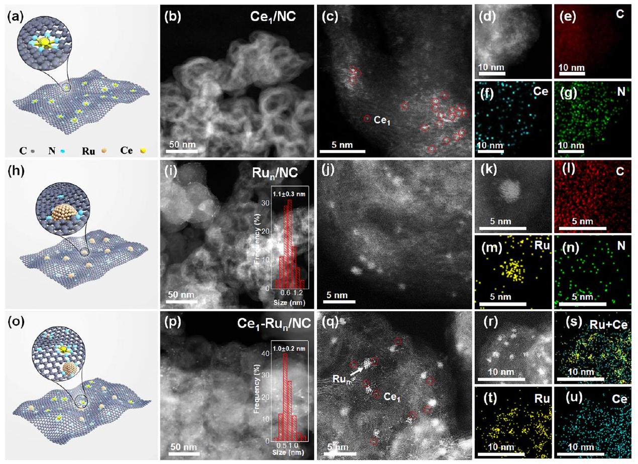
كمية التحميل من Ce في الـتم قياس المحفز ليكون بواسطة مطياف الانبعاث الضوئي للبلازما المقترنة بالحث (ICP-OES) كما هو موضح في الجدول S1. نظرًا لانخفاض تحميلات Ce، فإن القمم الواسعة لتشتت الأشعة السينية (XRD) لدعم الكربون فقط تمت ملاحظتها لـالمحفز كما هو موضح في الشكل S4. القياس المجهري من خلال تقنية مجهر الإلكترون الناقل ذو الحقل المظلم ذو الزاوية العالية (HAADF-STEM) لـالمحفز في الشكل S5-7 استبعد الجسيمات النانوية فيه. كما تم الكشف عنه بشكل أكبر من خلال قياس HAADF-STEM المصحح للانحراف (AC HAADF-STEM)، كانت أنواع Ce موزعة ذريًا فيالمحفز (الشكل 2ب-د). صور الخرائط العنصرية لتقنية التحليل الطيفي بالأشعة السينية المشتتة للطاقة (EDS) المقابلة لـالمحفز في الشكل 2e-g أكد أيضًا التوزيع المتجانس لأنواع Ce فيه.
وبالمثل، لقد وصفنا الـ و الـ المحفزات من خلال التقنيات المجهرية. كما هو موضح في صور HAADF-STEM لـالمحفز في الشكل 2i-k، مكشوف بالكاملنانوكلاسترز بحجم جزيئات متوسط كانت موزعة بالتساوي على دعمها NC. كانت صور الخرائط الأولية لـ EDS لمجموعة نانوية صغيرة في الكواشف (الشكل 21-n) كشفت عن طبيعة عنصر الروثينيوم (Ru). صور AC HAADF-STEM لـالمحفز في الشكل 2p-r أظهر أن متوسط حجم الجسيمات من الكتل النانوية Ru المعرضة بالكامل فيه كانصور الخرائط الأولية المقابلة لتقنية EDS لـأشار المحفز في الشكل 2s-u إلى أن إشارة عنصر الروثينيوم كانت مركزة على النانو كتل الصغيرة بينما كانت إشارة عنصر السيريوم متداخلة بشكل كبير مع توزيع الذرات الفردية، مما يشير إلى الوجود المشترك لنانو كتل الروثينيوم وذرات السيريوم الفردية فيها. لم يتم تحديد أي قمم حيود للروثينيوم في كلا الحالتين.العامل المساعد والمحفز كما هو موضح في الشكل S8 بسبب النانو كتل Ru الصغيرة جداً الموجودة فيها. كميات تحميل Ru منالعامل المساعد والعوامل المساعدة كانت تتعلق بـ (الجدول S1) بينما كان تحميل وزن Ce في كانكما تحدده قياسات ICP-OES.
بيئة التنسيق للروثينيوم والسيريم في، و تمت دراسة المحفزات بشكل إضافي من خلال قياسات هيكل الامتصاص الدقيق للأشعة السينية (XAFS). الشكل 3a يظهر طيف XAFS عند حافة Ru K-محفزحفاز وورقة روديوم مرجعيةتم عرض ذلك من خلال طيف XANES عند حافة Ru K المكبرة في الجزء السفلي من الشكل 3a، حيث كانت طاقات امتصاص الحافة لـمحفزالعوامل المساعدة كانت بين رقائق الروثينيوم والتي أظهرت أن حالات أكسدة الروديوم كانت بين 0 و +4.
من ناحية أخرى، كما اقترحته أفضل تحويلات فورييه الملائمة لطيف XAFS الممتد لحافة Ru K في الجدول S2 (تم عرض منحنيات الملاءمة المقابلة في الشكل S9، 10)، فإن متوسط عدد تنسيق RuRu لـكان المحفز حوالي 2، وهو ما كان أقل بكثير من ذلك الخاص بالنقينانوكلوستر ) كما هو موضح في الشكل S11. تشير هذه النتيجة إلى الوجود المشترك لذرات روديوم المفردة والنانوكلاسترز فيالعامل المساعد لأن ذرات الروديوم الفردية كانت مرتبطة فقط مع النيتروجين وبالتالي قللت من متوسط أعداد تنسيق الروديوم-الروديوم.المحفز. ملاحظة دقيقة مصححة للانحراف بتقنية HAADF-STEM لـالمحفز في الشكل S12 كشف أيضًا عن وجود ذرات مفردة من الروثينيوم فيالعامل المساعد. ذرات الروديوم الفردية المشحونة جزئيًا بشكل إيجابي فيالمحفز زاد بشكل حتمي من متوسط حالة الأكسدة للروثينيوم، مما أدى إلى زيادة طاقة الامتصاص عند الحافة لـأظهر المحفز زيادة ملحوظة مقارنةً بورق الروديوم المعدني كما ذُكر أعلاه. وقد وُجد أيضًا في الشكل 3a أن طاقة الحافة لـأظهر المحفز تحولًا سلبيًا بالنسبة لـمحفز وبالتالي تعزيز الكثافة المتوسطة لإلكترونات الروديوممحفزالذي ربما تم اشتقاقه من تبرع الإلكترون Ce كالفارق الوحيد بين Ru
الشكل 2 | القياسات المجهرية لـ، و ، على التوالي. النماذج الهيكلية لـ، و تم عرضها في (أ)، (ح)، و(ع) على التوالي. الصور AC HAADF-STEM في (ب-د)، (هـ-ز) صور رسم خرائط العناصر EDS لـ. صور HAADF-STEM، (ل-ن) EDS
صور الخرائط الأساسية لـ. ( صور AC HAADF-STEM، (صور الخرائط الأساسية EDS لـ. إدراجات و (p) هي المدرجات التكرارية لتوزيع حجم الجسيمات لعنقود روديوم النانوي في و ، على التوالي.
الشكل 3 | توصيفات حالات التنسيق والأكسدة لـ، و ، على التوالي. طيف XANES لحافة Ru K، (ب) تحويلات فورييه لاهتزازات EXAFS لحافة Ru K في فضاء R من ، ومرجع رقائق الروثينيوم و. و (د) منحنيات تركيب EXAFS من و الـ تحويل المويجات لإشارات EXAFSورق رو-طيف XANES عند حافة، (g) تحويلات فورييه لـ Ce-تذبذبات EXAFS عند حافة في فضاء R لـوالمرجع. ح ر طيف XPS لـ و الـ .
محفز NC وكان العامل المساعد هو وجود ذرات السيريوم الفردية فيالمحفز. للتحقق من هذه الفرضية، تم إجراء تحليل شحنة بادير بشكل إضافي. كما هو مقترح في الشكل S13، يمكن نقل إلكترونات Ce بسهولة إلى Ru مع عدد صافي من نقل الإلكترونات يبلغ 0.05 وبالتالي زاد من متوسط كثافة الإلكترونات في Ru فيالعامل المساعد بالنسبة لذلك منمحفز
تحويلات فورييه لتذبذبات EXAFS عند حافة Ru K في فضاء Rالعامل المساعد والمحفز في الشكل 3ب قدم ذروة تنسيق رئيسية أدنىمطابقة لتنسيق Ru-N. في هذه الأثناء، ذروة تنسيق Ru-Ru عند حوالي تم التعرف عليه أيضًا لكل منالعامل المساعد والعامل المساعد. ومع ذلك، تم تقليل شدة تنسيق الروثينيوم-روثينيوم بشكل كبير مقارنةً بـالتنسيق في كلا المحفزين، كاشفًا عن الفرق الملحوظ بين أعداد تنسيق Ru-Ru و Ru-N فيهماأظهرت منحنيات ملاءمة بيانات EXAFS للكاتاليستين في الشكل 3c و d والبيانات الملائمة المقابلة في الجدول S2 أن نسبة تنسيق Ru-N قد زادت بشكل كبير مقارنةً بتنسيق Ru-Ru في كلا الكاتاليستين. بالإضافة إلى ذلك، فإن التعزيزنسب التنسيق في و تم دعم المحفزات أيضًا بنتائج تحويل الموجات EXAFS كما هو موضح في الشكل 3e، حيث كانت شدة تنسيق Ru-N أقوى بشكل واضح من تنسيق Ru-Ru. كان هذا النتيجة مفهومة لأن تقليل حجم جزيئات Ru في المحفزين سيؤدي بشكل كبير إلى فصل رابطة Ru-Ru وتعزيز تنسيق Ru-N فيهما كما تم الإبلاغ عنه سابقًا..
في جانب آخر، الـ-edge XANES وطيف EXAFS الملائم لـالعامل المساعد والمرجعفي الشكل 3f و g والشكل S14 و 15، أظهرت مرة أخرى الطبيعة الذرية المفردة لأنواع Ce في الـالمحفز، الذي كان متسقًا مع ملاحظة AC HAADF-STEM المذكورة أعلاه. بخلاف ذلك، قمنا أيضًا بفحصالتنسيق فيالعامل المساعد والمرجعلمزيد من دراسة شكل وجود أنواع Ce فيالعامل المساعد. كما هو موضح من تحويلات فورييه لـتم تحديد قمة تنسيق عند 3.8 Å في طيف EXAFS عند حافة الشكل 3g للإشارة المرجعيةالذي تم تعيينه لـالتنسيق من خلال ملاءمة البيانات. في نفس الوقت،قدم المحفز ذروة تنسيق عندكان ذلك أقصر بشكل ملحوظ من تنسيق Ce-Ce. أشارت عملية ملاءمة البيانات بعناية إلى أن قمة التنسيق هذه لـتم اشتقاق المحفز منالمساهمة في الغلاف التنسيقي الثاني. لتأكيد ذلك بشكل أكبر، قمنا بإجراء تحليلات تحويل الموجات عالية الدقة EXAFS. كما هو موضح في الشكل S16، المرجععرضت أقصى شدة عند (مشتق من المساهمة) بينماأظهر المحفز أقصى شدة عند (نشأت من المساهمة). هذه النتيجة كشفت مرة أخرى عن غيابرابطة فيمحفز
علاوة على ذلك، فإن نقل الإلكترون بين ذرات السيريوم الفردية وعناقيد الروديوم النانوية فيتم إثبات العامل المساعد بشكل أكبر من خلال الروثينيومطيف XPS في الشكل 3h، حيث أن Ruذروة طاقة الربط لـتم إزاحة المحفز بشكل طفيف نحو السلبية مقارنة بـالعامل المساعد بسبب تبرع الإلكترونات من السيريوم إلى الروثينيوم. الطيف الكامل لـ XPS لـتم توفير المحفز أيضًا في الشكل S17 و N و ج تم التعرف بوضوح على قمم XPS للمواد الحفازة. ومع ذلك، بسبب انخفاض تحميل الكتلة لـ Ce في الـالمحفز، لم يتم العثور على قمة XPS لـ Ce في طيف XPS الاستكشافي. بفضل حد الكشف المنخفض لقياس XAFS المذكور، تم اكتشاف وجود Ce فيتم التحقق من المحفز بشكل جيد كما هو موضح في الشكل 2f.
تقييمات الكهروكيميائية لتفاعل الهيدروجين القلوي
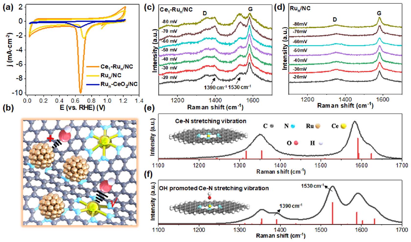
وفقًا للنتائج المبلغ عنهاكان تفكك الماء على المحفز يعتمد بشكل كبير على قوة امتصاص OH المقابلة. كانت الروابط الأقوى لـ OH مفيدة لاستقطاب جزيئات الماء وإطالتها وعادة ما تعزز تفكك الماء. لذلك، قمنا أولاً بإجراء قياسات الفولتمترية الدورية (CV) في محلول 1.0 م من هيدروكسيد البوتاسيوم لاستكشاف قوة امتصاص أيونات الهيدروكسيد علىمحفز NCالمحفز، على التوالي. عرض الشكل 4a أن شدة ذروة إزالة OH كانت حواليمنكان المحفز أقوى بكثير من ذلك لـالمحفز، مما يدل على زيادة امتصاص OH علىالعامل المساعد علىالمحفز. بالإضافة إلى ذلك، فإن قمة إزالة OH منكما أظهر المحفز تحولًا سلبيًا بالنسبة لذلك منالمحفز، الذي أكد بشكل أكبر على امتصاص OH الأقوى علىمحفز أكثر من ذلك علىمحفز. كعنصر تحكم، قمنا أيضًا بإعدادمُدمَج الجسيمات النانويةالعامل المساعد على دعم NCتم تقديم توصيفات مفصلة للحفاز في الشكل S18-22) مع تجمعات نانوية من الروثينيوم بحجم مشابه لتلك الخاصة بـ و المحفزات بينما مواقع Ce فيتم ربط المحفزات مع الأكسجين. وُجد أن شدة ذروة إزالة OH كانتتم تقليل المحفز بشكل ملحوظ بالنسبة لذلك منالعامل المساعد بسبب حجب الأكسجين لمواقع السيريوم. تشير هذه النتائج إلى أن OH كان أكثر ميلاً للارتباط بذرات السيريوم الفردية.المحفز كما هو موضح بوضوح في الشكل 4ب.
لتأكيد ذلك بشكل أكبر، قمنا بإجراء قياسات رامان في الموقع في محلول إلكتروليتي 1.0 M KOH تحت ظروف تفاعل الهيدروجين القلوي الحقيقية (تم توضيح نموذج الجهاز بشكل تخطيطي في الشكل S23). كما هو موضح في الشكل 4c، فإن قمم الاهتزاز في رامان عند و منتم تعزيز المحفزات تدريجياً مع انخفاض إمكانيات التفاعل خلال عملية الهيدروجين القلوي. بالمقابل،أظهر المحفز فقط قمم الاهتزاز لشريط D وشريط G لدعم الكربون (الشكل 4d) تحت نفس ظروف الاختبار.نظرًا لعدم وجود سجل لذروتي اهتزاز رامان الاثنين منمحفز في و ، قمنا أيضًا بإجراء المحاكاة النظرية لتحديد القمتين. من خلال التوفيق النظري لطيف رامان لـالمحفز قبل اختبار HER القلوي (الشكل 4e)، وجدنا أن قمم الاهتزاز رامان عند و تم تعيينهم إلىاهتزاز التمدد فيه، لكن القمتين كانتا ضعيفتين جداً قبل اختبار HER القلوي. وبالتالي، كان من المعقول افتراض أن تعزيز قمم اهتزاز رامان عند و كان مرتبطًا بـ OH أو H الناتج خلال عملية HER القلوية. لهذا الغرض، قمنا بدراسة تأثيرات كل من OH و H على اهتزاز تمدد Ce-N. ومن المثير للاهتمام، أنه عند إدخال OH إلى الـمواقع الـالمحفز، شدة قمم رامان المقابلة في و تم تعزيزها بشكل ملحوظ كما هو موضح في الشكل 4f، مما يتوافق جيدًا مع طيف رامان في الموقع في الشكل 4c. بالمقارنة، تم توضيح في الشكل S24 أن H كان له تأثير ضئيل على تعزيزاهتزاز التمدد عند و . من الواضح أن OH كان أكثر ميلاً للارتباط بذرات Ce المفردة من العامل المساعد خلال تفاعل الهيدروجين القلوي، مما جعل الكتل النانوية من الروثينيوم المعرضة بالكامل تعمل كمراكز لتطور الهيدروجين، وبالتالي تحقيق عكس الموقع النشط لتطور الهيدروجين بالنسبة إلىمحفز
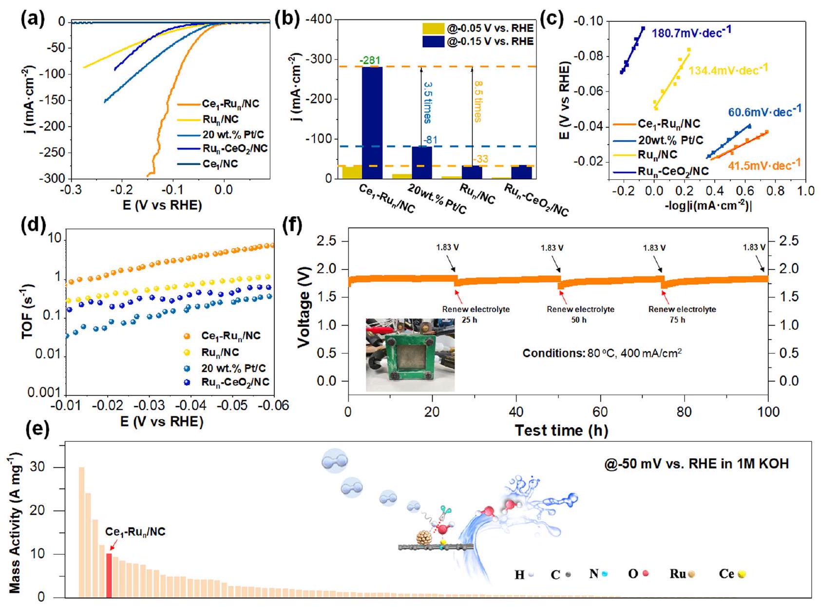
الثم تم استخدام محفزات تحكم أخرى لتقييم تفاعلات الهيدروجين القلوي الكهروكيميائية. كما هو متوقع،أظهر المحفز نشاطًا تحفيزيًا معززًا بشكل كبير مقارنةً بالمحفزات الضابطة الأخرى كما هو موضح في منحنيات الفولتمترية المسحية الخطية (LSV) في الشكل 5a. لتوضيح ذلك، فإن كثافة التيار لـالمحفز عند -0.05 فولت كان يصل إلى، والتي كانت 2.3 مرة و 4.6 مرة من و الـ المحفز كما هو موضح في الشكل 5ب. عندما وصلت جهد التفاعل إلى -0.15 فولت، كانت كثافة التيار لـتم تحسين المحفز إلىوأصبح 3.5 مرات منو 8.5 مرات منمحفز NC. علاوة على ذلك، فإن النشاط الكتلي لـكان المحفز أكبر بكثير منكما هو موضح في الشكل S25 (تم تقديم تفاصيل الحسابات في قسم الطرق وتم عرض تحميلات المعادن النشطة في الجدول S3). لقد قمنا أيضًا بقياس انحدارات تافل لهذه المحفزات تحت ظروف الحالة المستقرة باستخدام قياسات CA كما تم الاقتراح سابقًا.تم توضيحه في الشكل 5c أن
الشكل 4 | استكشاف التفاعلات بين و الـ محفز. منحنيات السيرة الذاتية لـ، و المحفزات المقاسة في محلول 1.0 م كوه.رسم تخطيطي يوضح اتجاه الترابط بين OH و Ce. طيف رامان في الموقع لـ (c)العامل المساعد و (د)
المحفز تحت ظروف الهيدروجين القلوية الحقيقية. منحنى رامان الملائم لـاهتزاز التمدد في الفراغمحفزمنحنى رامان الملائم لـاهتزاز التمدد لـفي وجود OH. الميل الناتج عن تافل لـمحفزكان أقل بكثير من ذلك لـمحفز، الـمحفز (134.4 مللي فولت لكل عقد) )، و الـ محفز )، مما يشير إلى حركيات تفاعل سريعة لتطور الهيدروجين على المحفز. بالإضافة إلى ذلك، فإن أصغر مقاومة لنقل الشحنة ( ) من الـ بين هذه المحفزات كما هو موضح في الشكل S26 قدمت دليلاً إضافياً على حركيات تفاعل الهيدروجين السريع. لفحص النشاط الجوهري لهذه المحفزات، قمنا بإجراء قياسات تردد الدوران (TOF) لهذه المحفزات في نطاق الجهد من -0.01 فولت إلى -0.06 فولت. وقد وُجد أن قيم TOF لـالعامل المساعد وكان المحفز أعلى بشكل واضح منكما هو موضح في الشكل 5 د. علاوة على ذلك، مع مساعدة ذرات السيريوم الفردية، فإن قيمة TOF لـكان المحفز أكبر بكثير من ذلك لـالعامل المساعد. ومع ذلك، فإنأظهر المحفز قيمة TOF مخفضة بوضوح مقارنةً بتلك الخاصة بـالمحفز، الذي ربما اشتق من ضعيف قوة امتصاصه لـ OH كما يتضح من نتائج CV المذكورة أعلاه في الشكل 4a.
لمقارنة نشاط تفاعل الهيدروجين القلويمحفز بتقنية متطورةالعامل المساعد، لقد أعددنا أيضًاالعامل المساعد عن طريق تقليلدعم NC الم impregnated فيمع الهيدروجين (يرجى مراجعة قسم الطرق لمزيد من التفاصيل). صور HAADF-STEM وصور HAADF-STEM المصححة للانحراف لـالعامل المساعد في الشكل S27 كشف عن الوجود المشترك لذرات الروديوم الفردية الموزعة بشكل موحد والنانوكلاسترزفيالمحفز. وُجد أن نشاط تفاعل الهيدروجين القلويكان المحفز أقل بكثير من ذلك لـالمحفز كما هو مقترح من خلال منحنيات LSV الخاصة بهم وقيم TOF للمحفزين كما هو موضح في الشكل S28. علاوة على ذلك، على الرغم من التحميلات المماثلة من Ru بينالعامل المساعد والمحفز، النشاط الكتلي المعاير لكل ملليغرام من الروثينيومكان المحفز أعلى بشكل ملحوظ من المحفز كما هو موضح في الشكل S29، الذي كشف عن كفاءة أعلى لذرات الروثينيوم في تطور الهيدروجين القلوي علىمحفز NC أكثر من ذلكمحفز
لإجراء مقارنة دقيقة لنشاط الكتلة بينالمحفزات والمحفزات القلوية المعتمدة على الروثينيوم التي تم الإبلاغ عنها سابقًا، قمنا بالإشارة إلى أكثر من 100 ورقة بحثية نُشرت في السنوات الأخيرة كما هو ملخص في الجدول S4-5 والشكل 5e. يمكن تحديد أن الأنشطة الكتلية لـتم قياس المحفز عند -0.1 فولت و -0.05 فولت وكان أفضل من معظم النتائج المبلغ عنها. لفحص الإمكانية التطبيقية العملية لـالمحفز، لقد قمنا بقياس متانة الـمحفز على جهاز التحليل الكهربائي للماء باستخدام غشاء تبادل الأنيونات القلوي (AEMWE) باستخدامكعامل حفاز كاثودي ورغوة النيكل كعامل حفاز أنودي. منحنى الكرونوپوتنشيومتر الذي تم الحصول عليه من خلال ضبط درجة حرارة التفاعل عندوكثافة التيار الناتجة عندفي الشكل 5f اقترح أنأظهر المحفز استقرارًا جيدًا جدًا خلال اختبار لمدة 100 ساعة. لقد قمنا أيضًا بتوصيف الـالمحفز بعد اختبار الاستقرار باستخدام مجموعة متنوعة من التقنيات. للبدء، كما هو موضح في صور HAADF-STEM للمحفز المستهلكالمحفز في الشكل S30a، b، موزع بشكل متساوٍنانوكلاسترز بحجم جزيئات متوسطتم تحديده، متوافقًا جيدًا مع حجم الجسيمات الأولي لهعلاوة على ذلك، فإن صور HAADF-STEM المصححة للانحراف بعد التفاعلالعامل المساعد في الشكل S30c و d كشف عن التعايش بين ذرات السيريوم المفردة الموزعة بشكل متجانس والنانوكلاسترات على دعم NC، والذي تم التحقق منه أيضًا من خلال صور رسم الخرائط العنصرية EDS المقابلة في الشكل S30e-g. أظهرت نتائج هذه التوصيفات الاستقرار القوي لـالمحفز. بالإضافة إلى ذلك، قمنا أيضًا بإجراء قياس الفولتموغرام الدوري المستمر لفحص استقرار الـالمحفز. كما هو موضح في الشكل S31، بعد 6000 دورة من دورات الفولتموجرافيا الدورانية، منحنى LSV لـظل المحفز متداخلاً تقريبًا
الشكل 5 | تقييمات تفاعل الهيدروجين الكهربائي القلويوعوامل تحكم أخرى. منحنيات LSV للعوامل المحفزة المختبرة.مقارنة كثافات التيار عند -0.05 فولت و -0.15 فولت للمواد المحفزة المختبرة. رسومات تافل لـوالتجاريالمحفزات. منحنيات قيمة TOF لـ و الـ العوامل المساعدة في النطاق المحتمل يتراوح من -0.01 فولت إلى -0.06 فولت. مقارنة النشاط الكتلي لتفاعل الهيدروجين القلويالمحفز مع المحفزات المعتمدة على الروثينيوم التي تم الإبلاغ عنها سابقًا عند -0.05 فولت مقابل RHE.منحنى الكرونوپوتنشيومترمحفز تحت ظروف AEMWE عند درجة حرارة التفاعلوكثافة تياركانت الصورة المصغرة (f) لآلة AEMWE. مع أول واحدة لها، التي كشفت مرة أخرى عن المتانة الممتازة لـمحفز
التحقيقات النظرية لـنشاط المحفز القلوي المتفوق في تفاعل الهيدروجين
تم إجراء حسابات نظرية الكثافة من أول مبدأ (DFT) مع ت polarisation الدوران لاستكشاف أصل النشاط الممتاز لتفاعل الهيدروجين القلوي.العامل المساعد. النماذج الهيكلية لـ و تم بناء المحفزات استنادًا إلى بيانات تركيب EXAFS، حيث تم تنسيق ذرة السيريوم المفردة مع ست ذرات نيتروجين، وتم تثبيت ذرة الروثينيوم المفردة بواسطة أربع ذرات نيتروجين من دعم NC. نظرًا لوجود ذرات الروثينيوم المفردة معًا والنانوكلاسترز فيمحفز، لقد أنشأنا نظامًا مزدوجًانموذج لمحاكاة الـالعامل المساعد من خلال أخذ حجم الجسيمات في الاعتبارالنانوكلوستر (1 نانومتر، الشكل S11) وذرات الروثينيوم الفردية المجاورة لهكما تم استخدامه بشكل شائع في التقارير السابقة لمحاكاة المحفز الموحد مع وجود ذرات روديوم مفردة وكتل نانوية/جزيئات نانوية من روديوم.. تم تقديم جميع تفاصيل الهيكل للنماذج المُنشأة في المعلومات الداعمة (الأشكال S32-35). للبدء، يجب ملاحظة أن ذرات الروديوم الفردية النقية على دعم NC لم تكن كافية لتفكيك جزيء الماء، والذي اعتُبر الخطوة المحددة لمعدل تفاعل الهيدروجين القلوي. كما هو موضح في الشكل S36، كانت حاجز الطاقة الحرة لجزيء الماء عند التفكيك فوق ذرة الروديوم الفردية كبيرة تصل إلى 1.03 إلكترون فولت، مما يدل على خصائصها الضعيفة في تفكيك الماء وبالتالي انخفاض القلوية.
نشاط HER. لدراسة نشاط HER القلوي لذرات الروديوم الفردية بشكل أعمق، قمنا بتخليقالمحفز (تم توضيح التفاصيل الاصطناعية في جزء الطرق). تشكيل ذرات الروديوم الفردية فيتم تأكيد المحفز من خلال صور HAADF-STEM المصححة للانحراف له في الشكل S37. كما تم الكشف عن ذلك بشكل أكبر من خلال نتائج تقييم HER القلوي (منحنى LSV) في الشكل S38، حيث أن النشاط التحفيزي لـكان المحفز أقل بكثير من ذلك لـالعامل المساعد. في هذه الأثناء، الثنائيالمواقع قدمت حاجز طاقة غيبس الحرة منخفض جداً لتفكيك جزيئات الماء مقارنةً بتلك الخاصة بذرات الروديوم الفردية النقية (الشكل S1 والشكل S36)، مما يجعل الثنائيحدد نموذج هيكلي معقول لمحاكاةمحفز NC. بقدر ما يتعلق الأمر بـكان المحفز مقلقًا، حيث أن ذرات الروديوم الفردية وذرات السيريوم الفردية فيه لم تكن كافية لتفكيك الماء من حيث الحواجز الكبيرة للطاقة الحرة غيبس لتفكيك الماء كما هو موضح في الشكل S36 والشكل S39، على التوالي. مع الأخذ في الاعتبار أن نتائج الاختبار التجريبية في الشكل 5 أظهرت أن نشاط تفاعل الهيدروجين القلوي لـكان المحفز أعلى بكثير منالعامل المساعد، لذا كان من المعقول استخدام الثنائينموذج لمحاكاةالعامل المساعد لأنه كان الاختلاف الهيكلي الوحيد بينالعامل المساعد ومحفز
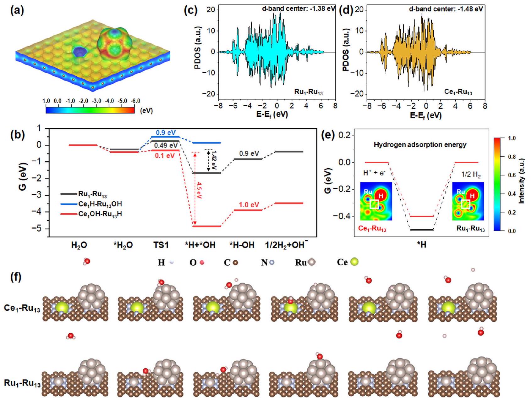
تظهر الشكل 6أ أنكان الحفاز يمتلك مجالًا ميكروكهربائيًا بسبب الفرق الملحوظ في توزيع الجهد الكهروستاتيكي بين ذرات السيريوم الفردية والكتل النانوية المعرضة بالكامل من الروثينيوم. وبالتالي، كانت جزيئات الماء قادرة على تم إطالة عند الاتصال بـالعامل المساعد. وُجد أنرابطة الماء تم إطالتها بشكل ملحوظ منإلىعند الامتصاص علىالعامل المساعد، وبالتالي يفضل بشكل فعال تنشيط الماء. نظريًا، كان للماء نمطان محتملان للتنشيط علىالمحفز: (ط) مجموعات OH مرتبطة بذرات السيريوم الفردية بينما ترتبط ذرات الهيدروجين مع الكتل النانوية للروثينيومالمسار)؛ و (ii) ذرات الهيدروجين المرتبطة بذرات السيريوم الفردية بينما المجموعات الهيدروكسيلية مرتبطة بعناقيد الروديوم النانوية (الطريق). لذلك، قمنا بإجراء حسابات DFT لكلا الطريقين. كما هو موضح في الشكل 6b،كانت المسار ماصًا للحرارة بمقدار 0.6 إلكترون فولت بينماكانت المسار exothermic بشكل خاص بمقدار 4.5 eV. الديناميكا الحرارية المختلفة بشكل حاد لـالطريق ومن المحتمل أن تكون المسار مشتقة من الأكسوفيلية المميزة للروثينيوم والسيريميوم. بالمقارنة مع الروثينيوم من الكتلة d، كان السيريميوم من الكتلة f أكثر أكسوفيلية بكثير.الذي من خلاله كان Ce أكثر ميلاً للارتباط مع OH بدلاً من H، مما يجعلمسار أكثر تفضيلاً من الناحية الديناميكية الحرارية.
أظهرت حسابات DFT أيضًا أن الطاقة الطاردة للحرارة للثنائيالموقع (4.5 إلكترون فولت) كان 3.2 مرة من الثنائيالموقع (1.42 إلكترون فولت) في عملية تنشيط الماء، التي كشفت أن الثنائي كانت المواقع أكثر ملاءمة من الناحية الديناميكية الحرارية لتفكيك جزيئات الماء من الثنائي المواقع. بالإضافة إلى ذلك، حاجز طاقة تفكك الماء عبر الثنائيموقعكان أيضًا أقل بشكل ملحوظ من ذلك على الثنائيموقع. لذلك، الثنائي كانت المواقع مفيدة من الناحيتين الديناميكية الحرارية والحركية لتفكيك جزيئات الماء بالنسبة للثنائي المواقع. بعد تفكك الماء، تم ربط OH مع ذرات السيريوم الفردية المحبة للأكسجين بينما تم امتصاص H على الكتل النانوية من الروثينيوم المكشوفة بالكامل.
للحصول على فهم نظري لتكوين الهيدروجين وإزالة OH على السطح المزدوجالمواقع والمواقع، قمنا أيضًا بإجراء حسابات لقوة ارتباط الهيدروجين ( ) وحواجز طاقة إزالة OH لكلا النموذجين. بسبب غنى الإلكترونات في Ru في المحفز كما تم الكشف عنه من خلال نتائج XANES و XPS المذكورة أعلاه، مركز حزام d المحسوب لـالنانوكلاسترات فيالمحفز ( -1.48 eV ) أظهر انخفاضًا واضحًا مقارنةً بما هو عليهمحفزكما هو موضح في الشكل 6c، d. وفقًا للتقارير السابقةعادةً ما يُعزى انخفاض تفاعل معدن الروثينيوم تجاه تفاعل تقليل الهيدروجين إلى قوة امتصاصه للهيدروجين التي تعيق نقل الهيدروجين وتشكيل. انخفاض مركز نطاق d لـالنانوكلاسترات فيالعامل المساعد سيضعف بسهولة قوة ارتباط الهيدروجينلتمكين نقل الهيدروجين بشكل أكثر جدوى. كما هو موضح في الشكل 6e،من الثنائيكان الموقع واضحًا أنه أقرب إلى القيمة المثلىمن الثنائية الموقع، الذي جعلمحفز أكثر كفاءة لتطور الهيدروجين منالمحفز. من ناحية أخرى، تم حساب طاقات امتصاص الهيدروجين للثنائيالموقع والثنائيالموقع عبر طريقة “نموذج القطب الهيدروجيني الحاسوبي”كانت أكبر بوضوح من تلك التي تم قياسها تجريبيًا لجهود البداية لها. كانت هذه النتيجة ناتجة عن حقيقة أن نظام التفاعل كان مجموعة كانونية كبيرة، والتي تأثرت بشكل كبير بتأثير الاستقطاب. ونتيجة لذلك، على الرغم من أن الطاقة التفاعلية المحسوبة اقترحت اتجاه تفاعل معقول، إلا أن قيمة الطاقة التفاعلية المحسوبة عرضت عادة انحرافًا ملحوظًا عن النتيجة المكتسبة تجريبيًا. لذلك، قمنا بإجراء المزيد من حسابات طاقة امتصاص الهيدروجين للثنائيالموقع والثنائيالموقع، على التوالي، باستخدام طريقة “نموذج الحلول الضمنية CANDEL”. كما هو موضح في الشكل S40، تم حساب طاقات امتصاص الهيدروجين على الثنائيالموقع وعلى الثنائي كانت قيم الموقع باستخدام هذه الطريقة -0.096 eV و -0.142 eV على التوالي، والتي كانت أقرب إلى الجهود الابتدائية المقاسة تجريبيًا منه إلى تلك المحسوبة من خلال “نموذج القطب الهيدروجيني الحاسوبي”. من ناحية أخرى، كشف تحليل وظيفة توطين الإلكترون (ELF) (في الجزء السفلي من الشكل 6e) عن درجة أضعف من توطين الإلكترون في تم تحديد منطقة الترابط للثنائيموقع أكثر من الثنائيالموقع، الذي من شأنه أن يضعف بشكل كبير قوة الروابط الهيدروجينية على الثنائيموقع لتكوين الهيدروجين بشكل أكثر ملاءمة.
في الختام، نبلغ أن توحيد ذرات السيريوم الفردية ذات الأكسفيلية العالية والعناقيد النانوية للروثينيوم المكشوفة بالكامل على دعم كربوني مُوظف بالنيتروجين يمكن أن يعكس بكفاءة مراكز تطور الهيدروجين القلوية إلى الشكل الأكثر نشاطًا.جانب النانوكلستر، الذي عزز بشكل كبير نشاط تفاعل الهيدروجين القلوي للمحفز. تم تأكيد موقع النشاط السهل العكسي لتطور الهيدروجين بشكل جيد من خلال قياسات CV وقياسات رامان في الموقع والحسابات النظرية. ومن الجدير بالذكر أن النشاط الكتلي لـمحفزكان (عند -0.05 فولت) متفوقًا على معظم المحفزات القلوية المعتمدة على الروثينيوم المبلغ عنها حتى الآن. في الوقت نفسه، كشفت قياسات الكرونو بوتنشيومتر التي أجريت على جهاز AEMWE عن متانته الممتازة، مما أظهر إمكانيات كبيرة للتطبيقات العملية. قد توفر هذه النتيجة رؤى جديدة في تصميم محفزات قلوية فعالة للغاية من خلال تنظيم مراكز تطور الهيدروجين بشكل عقلاني.
طرق
المواد
كانت جميع المواد الكيميائية من الدرجة التحليلية واستخدمت كما هي دون مزيد من التنقية. تم شراء كلوريد الروديوم واليوريا من شركة ماكلين للمواد الكيميائية الحيوية المحدودة. تم الحصول على اليوريا والدعم الكربوني (XC-72) من شركة العيدين للتكنولوجيا الحيوية المحدودة. تم شراء نترات السيريوم سداسية الماء من شركة سينوفارم للمواد الكيميائية. تم شراء المحفزات التجارية Pt/C بنسبة 20% من شركة سيغما-ألدريتش. تم الحصول على بوليمر نافيون PFSA بمحتوى بوليمر 5% من شركة دوبونت. تم الحصول على الإيثانول من شركة تونغوانغ للمواد الكيميائية الدقيقة في بكين. تم شراء ورق الكربون المحب للماء من شركة كيلود للتكنولوجيا والمعدات التجريبية المحدودة.
تحضيردعم الكربون الوظيفي (NC)
تم تحضير الدعامات الكربونية المفعلة بالنيتروجين وفقًا لتقاريرنا السابقة.. عادةً ما يتم طحن 2 جرام من كربون XC-72 بشكل متجانس مع 3 جرام من اليوريا. بعد ذلك، تم تسخين الخليط عند لمدة ساعتين و لمدة 4 ساعات أخرى في بوتقة محكمة الإغلاق. ثم تم غسل المنتج بشكل كافٍ بالماء وتجفيفه فيبين عشية وضحاها.
تركيب الـ
إعدادتم تحضيره عن طريق طريقة النقع. لتوضيح الأمر، 6 ملغ منتم إضافتها أولاً إلى
20 مل من الماء المنزوع الأيونات وتم تحريكه لذوبان سلفيد السيريوم. بعد ذلك، تمت إضافة 0.1 جرام من دعم NC إلى المحلول السابق. بعد التحريك الإضافي لمدة 12 ساعة، تم طرد الخليط في جهاز الطرد المركزي وغسله جيدًا، وتم تجفيف المنتجات الصلبة الناتجة عندبين عشية وضحاها. أخيرًا، تم تقليل المساحيق المستخرجة بالهيدروجين فيلمدة ساعتين.
تحضير الـ
المُعَدّثم تم السماح بمعالجة الحمض ( ) بين عشية وضحاها. بعد الغسل الكافي والطرد المركزي، تم تجفيف المنتجات الصلبة الناتجة في بين عشية وضحاها لجعل الـمحفز
تفاصيل التحضير لـ
أولاً، 2.5 ملغ منتم إذابتها في 10 مل من الماء المنزوع الأيونات. بعد ذلك، 0.05 جرام منتمت إضافته إلىمحلول تحت تحريك خفيف. بعد التحريك لمدة 12 ساعة أخرى، تم غسل الخليط بشكل كافٍ، وتم جمع المنتجات الصلبة الناتجة وتجفيفها فيبين عشية وضحاها. أخيرًا، تم تقليل المساحيق المستخرجة عندلمدة ساعتين تحت جو من الهيدروجين.
الطريقة الاصطناعية لـ
للبدء، 2.5 ملغ منتم إضافة إلى 10 مل من الماء المنزوع الأيونات وتم التحريك حتى تذوب مسبقات الروثينيوم تمامًا. بعد ذلك، تم إضافة 0.05 جرام من دعم NC إلىمحلول تحت تحريك خفيف. بعد التحريك الإضافي لمدة 12 ساعة، تم طرد الخليط بشكل كافٍ وغسله. تم جمع المساحيق الصلبة الناتجة وتجفيفها عندبين عشية وضحاها. أخيرًا، تم تقليل المساحيق المستخرجة بالهيدروجين فيلمدة ساعتين.
تحضير الـ
تحضير الـكان المحفز مشابهًا لذلك الخاص بتخليقالعامل المساعد. الاختلاف الوحيد كان أنه خلال تقليل الـالمحفز، تم ضبط درجة حرارة الاختزال على.
تحضير الـ
تركيبكان المحفز يعتمد على طريقة النقع. للبدء، تم استخدام كمية صغيرة منتم إذابتها في 10 مل من الماء المنزوع الأيونات. بعد ذلك، تمت إضافة 0.05 جرام من دعم NC إلى المحلول وتم التحريك لمدة 12 ساعة. بعد الطرد المركزي الإضافي، تم جمع المساحيق الصلبة المكتسبة وتجفيفها فيبين عشية وضحاها. أخيرًا، تم تقليل المساحيق المستخرجة باستخدام الهيدروجين فيلمدة ساعتين.
تحضير الـ
تحضير الـكان كما يلي: 2.5 ملغ منتمت إضافتها أولاً إلى 10 مل من الماء المنزوع الأيونات تحت تحريك خفيف. بعد ذلك، 0.05 جرام منتمت إضافته إلىمحلول تحت التحريك. بعد التحريك لمدة 12 ساعة أخرى، تم طرد الخليط مركزيًا وغسله جيدًا. ثم تم جمع المنتجات الصلبة المكتسبة وتجفيفها فيبين عشية وضحاها. بعد ذلك، تم تقليل المساحيق المستخرجة باستخدام الهيدروجين فيلمدة ساعتين.
تفاصيل الحسابات النظرية
نماذج الهيكلية للوح و الـ تم بناءها مع الأخذ في الاعتبار بيانات ملاءمة EXAFS في الجدول S1 لبناء تنسيق Ce-N و Ru-N. تم إدخال فراغ بسمك 20 Å في-توجيه لتجنب التفاعل الاصطناعي بين الصور الدورية. تم إجراء حسابات DFT الموجهة بالدوران باستخدام حزمة المحاكاة الأولية فيينا (VASP 5.4.4) مع دالة التبادل والتفاعل Perdew-Burke-Ernzerhof (PBE)تم إثبات الإلكترونات الأساسية من خلال طريقة الموجة المعززة المتوقعة.حيث إن الإلكترونات التكافؤية (سي: 5s5p4f5d6s، رو: 4p5s4d، أ: ، ن: , ج: , ح: تم توسيع ( ) على مجموعات أساس الموجات المسطحة بحد طاقة يبلغ 520 إلكترون فولت. تم استخدام عينة نقطة غاما بناءً على طريقة مونكهورست-باك لحساب هياكل الشرائح. استخدمت الحسابات الذاتية الاتساق عتبة طاقة تقارب قدرهاوعتبة القوة من. من ناحية أخرى، تصحيحات فان der Waals باستخدام طريقة DFT-D3 بدون تخفيفتم أخذ بيانات Grimme في جميع الهياكل. تم إجراء تحليل شحنة Bader بعناية بعد كل استرخاء. تم تنفيذ طريقة حافة الصورة المتسلقة المرنة (CI-NEB) لإظهار حواجز الطاقة لحالات الانتقال خلالالانفصال. تم الحصول على تغييرات الطاقة الحرة لجيبس من خلال المعادلة، حيث و كانت التغيرات في طاقة النقطة الصفرية والإنتروبيا، كما تم تحديدها من خلال أخذ الأنواع الممتصة وجزيئات الماء في وضع الاهتزاز التوافقي بعين الاعتبار.طريقة حافة الصورة المتسلقة باستخدام شريط مطاطيتم استخدامه لاستكشاف حالة الانتقال وتحديد حواجز التفاعل المقابلة. تم حساب طاقة امتصاص الهيدروجين باستخدام طريقة نموذج القطب الهيدروجيني الحسابي وطريقة نموذج الذوبان الضمني CANDEL. خلال الحسابات، تم استرخاء الهياكل أثناء التفاعل بالكامل حتى كانت القوة النهائية على كل ذرة أقل منطاقة امتصاص الهيدروجين على نماذج الهيكل المزدوجالموقع والثنائيتم الحصول على الموقع من خلال إضافة المساهمة الاهتزازية لـ للطاقة الإلكترونية لأنظمة التفاعل المقابلة. تم حساب طيف رامان من خلال حسابات DFT المنفذة بواسطة برنامج Gaussian 16 (A.03). تم بناء نموذج العنقود الذي يتركز حول ذرة السيريم استنادًا إلى النموذج الدوري مع تثبيت ذرات الكربون الحافة وإشباعها بذرات الهيدروجين. تم إجراء تحسين الهندسة وتحليل التردد عند مستوى PBEO/ مستوى النظرية. تم رسم طيف رامان بواسطة حزمة Multiwfnمع عامل توسيع التردد 0.988 وعرض النصف الأقصى للقمم.
تفاصيل التوصيفات
تم تحليل الهياكل البلورية للمواد بواسطة حيود الأشعة السينية بالمسحوق (XRD، Rigaku SmartLab، Cu Kإشعاعتمت دراسة حالات الأكسدة للروثينيوم باستخدام مطيافية الأشعة السينية للألكترونات (XPS، ثيرمو إيسكالاب 250XI أل ك) ( تم إجراء تحليل المجهر الإلكتروني الناقل (TEM) على جهاز FEI Talos F200X. تم تشغيل المجهر الإلكتروني الناقل بتقنية الحقل المظلم الحلقي بزاوية عالية عند 200 كف. تم إجراء ملاحظات STEM بدقة ذرية على جهاز ThemisZ (Titancubed•ThemisZ:300).تم تحديد كميات العناصر في العينات بواسطة جهاز ICP-OES من شركة أليجنت ICPOES730. كل من حافة روثينيوم K وتم جمع طيف امتصاص الأشعة السينية عند حافة X-ray في محطة XAS (BL14W1) في منشأة الإشعاع المتزامن في شنغهاي. تم تشغيل حلقة تخزين الإلكترون عند 3.5 جيجا فولت مع تيار أقصى قدره 250 مللي أمبير. تم جمع البيانات باستخدام مقياس الطيف مزدوج البلورة Si (311) في وضع الفلورة لكلاهما.حد Ce وحد K من Ru. تم تسجيل جميع بيانات الطيف في درجة حرارة الغرفة. من خلال استخدام غرفة تأين ثالثة، تم استخدام معيار ورقة Ru،، و تم قياسها في نفس الوقت مع العينة لأغراض معايرة الطاقة. تمثل ملفات هيكل الامتصاص الدقيق للأشعة السينية الممتدة (EXAFS) لحافة روثينيوم K و سيريومتمت معالجة الحواف بناءً على الإجراءات القياسية لوحدة ATHENA المطبقة في حزم برامج IFEFFIT.تم الحصول على طيف EXAFS الموزون عن طريق طرح الخلفية بعد الحافة من الامتصاص الكلي ومن ثم تطبيعها بالنسبة لخطوة قفزة الحافة.-مرجحتم تحويل ملفات التعريف إلى الفضاء الحقيقي (R) باستخدام نوافذ هانينغ ) لفصل مساهمات EXAFS من قذائف التنسيق المختلفة. للحصول على معلمات هيكلية كمية حول الذرات المركزية، تم إجراء ملاءمة معلمات منحنى بطريقة المربعات الصغرى باستخدام وحدة ARTEMIS من حزم برامج IFEFFIT.
تم إجراء قياسات كيميائية كهربائية لتفاعل الهيدروجين القلوي (HER) من خلال محطة كيميائية كهربائية أوتولاب (ميتروهيم، سويسرا) في محلول 1 م KOH عند درجة حرارة الغرفة. تم إدارة وحدات الاختبارات الكيميائية الكهربائية بواسطة برنامج الكمبيوتر نوفا 2. تم استخدام نظام ثلاثي الأقطاب لدراسة الأداء الكيميائي الكهربائي، حيث كان القطب المضاد والقطب المرجعي عبارة عن قضيب جرافيت وقطب زئبقي/أكسيد الزئبق، على التوالي. تم معايرة جميع قيم الجهد المستخدمة في هذا العمل إلى القطب الهيدروجيني القابل للعكس (RHE)، باستخدام المعادلة التالية:
لإعداد حبر المحفز، تم توزيع المحفز بشكل متجانس فيحل مكون منالإيثانول ونافيوين تحت الصوتنة.تم تحميل الحبر المذكور أعلاه على قطب الكربون الزجاجي بقطر 3 مم لاختبارات تفاعل الهيدروجين القلوي. بدلاً من ذلك،تم تحميل حبر المحفز علىورق الكربون المحب للماء لاختبارات الاستقرار. خلال جميع تقييمات HER القلوية، تم استخدام خلية H لإزالة تأثيرات الأنود. تم الحصول على منحنيات الاستقطاب عن طريق مسح الجهد من 0.1 إلى -0.325 فولت مقابل RHE عند درجة حرارة الغرفة بمعدل مسحاستخدام تعويض iR. استقرار الـتمت فيعبر تقنية الكرونو بوتنشيومترية.
: التيارات الهيدروجينية المقاسة، أ ؛ N : عدد نقل الإلكترون (2 لـ ); ثابت فاراداي؛ كتلة المحفز على القطب، جرام؛ تحميل المعدن من المحفز وفقًا لنتائج ICP-OES؛ الكتلة الذرية للروثينيوم؛ الكتلة الذرية للبلاتين؛ ح: متوسط حجم الجسيمات. تفاصيل الحساب لنشاط الكتلة مدرجة أدناه:
أنا: التيارات المقاسة، أ; كتلة المحفز على القطب، جرام؛ تحميل المعدن من المحفز استنادًا إلى قياسات ICP-OES؛
تفاصيل قياسات رامان في الموقع
تم إجراء طيف رامان على جهاز inVia Reflex المدمج مع ميكروسكوب كونفوكالي. تم الحصول على جميع الأطياف تحت درجة حرارة الغرفة مع تحفيز بطول موجي 532 نانومتر. تم إجراء المعايرة باستخدام ذروة (معيار شريحة السيليكون). لتجنب تلف العينات، تم تقليل قوة الليزر بمقدار 10 مرات. تم إجراء قياسات رامان في الموقع على خلية تفاعل كيميائي كهربائي مصنوعة محليًا باستخدام نظام ثلاثي الأقطاب قياسي في محلول إلكتروليتي 1.0 م KOH. حيث، تم استخدام القطب الكهربائي كقطب مرجعي، وكان سلك البلاتين يعمل كقطب مضاد. لتحضير القطب العامل، تم أولاً تفريق المحفز بالموجات فوق الصوتية في 550 مل من المذيب (ماءالإيثانول ومحلول نافيون). بعد ذلك،تم تحميل الحبر المتجانس على ورقة كربون بمساحةتم الحصول على بيانات رامان في الموقع من قياسات الكرونوأمبيرومترية التي أجريت في نطاق الجهد من 0 مللي فولت إلى -80 مللي فولت مقابل
RHE. تم تسجيل الأطياف في ظروف الحالة المستقرة من خلال الثبات عند الجهد المطلوب لمدة لا تقل عن 120 ثانية.
توفر البيانات
جميع بيانات الدراسة مدرجة في النص الرئيسي والمعلومات الداعمة. يتم توفير بيانات المصدر كملف بيانات مصدر.
References
Chu, S. & Majumdar, A. Opportunities and challenges for a sustainable energy future. Nature 488, 294-303 (2012).
Turner, J. A. Sustainable hydrogen production. Science 305, 972-974 (2004).
Ursua, A., Gandia, L. M. & Sanchis, P. Hydrogen production from water electrolysis: current status and future trends. Proc. IEEE 100, 410-426 (2012).
Carmo, M., Fritz, D. L., Mergel, J. & Stolten, D. A comprehensive review on PEM water electrolysis. Int. J. Hydrog. Energy 38, 4901-4934 (2013).
Vincent, I. & Bessarabov, D. Low cost hydrogen production by anion exchange membrane electrolysis: a review. Renew. Sustain. Energy Rev. 81, 1690-1704 (2018).
Mahmood, N. et al. Electrocatalysts for hydrogen evolution in alkaline electrolytes: mechanisms, challenges, and prospective solutions. Adv. Sci. 5, 1700464 (2018).
Chen, Z., Duan, X., Wei, W., Wang, S. & Ni, B.-J. Recent advances in transition metal-based electrocatalysts for alkaline hydrogen evolution. J. Mater. Chem. A. 7, 14971-15005 (2019).
Subbaraman, R. et al. Trends in activity for the water electrolyser reactions on 3d M(Ni,Co,Fe,Mn) hydr(oxy)oxide catalysts. Nat. Mater. 11, 550-557 (2012).
Wang, X. et al. Strategies for design of electrocatalysts for hydrogen evolution under alkaline conditions. Mater. Today 36, 125-138 (2020).
Kim, J. et al. Tailoring binding abilities by incorporating oxophilic transition metals on 3D nanostructured Ni arrays for accelerated alkaline hydrogen evolution reaction. J. Am. Chem. Soc. 143, 1399-1408 (2021).
Zhou, K. L. et al. Platinum single-atom catalyst coupled with transition metal/metal oxide heterostructure for accelerating alkaline hydrogen evolution reaction. Nat. Commun. 12, 3783 (2021).
Zheng, Y. et al. High electrocatalytic hydrogen evolution activity of an anomalous ruthenium catalyst. J. Am. Chem. Soc. 138, 16174-16181 (2016).
Hu, Q. et al. Subnanometric Ru clusters with upshifted D band center improve performance for alkaline hydrogen evolution reaction. Nat. Commun. 13, 3958 (2022).
Mao, J. et al. Accelerating water dissociation kinetics by isolating cobalt atoms into ruthenium lattice. Nat. Commun. 9, 4958 (2018).
Yang, J. et al. Efficient and Robust hydrogen evolution: phosphorus nitride imide nanotubes as supports for anchoring single ruthenium sites. Angew. Chem., Int. Ed. 57, 9495-9500 (2018).
He, Q. et al. Achieving efficient alkaline hydrogen evolution reaction over a Ni5P4 Catalyst incorporating single-atomic Ru sites. Adv. Mater. 32, 1906972 (2020).
. et al. A small change in the local atomic environment for a big improvement in single-atom catalysis. J. Mater. Chem. A. 9, 4184-4192 (2021).
He, Q. et al. Synergic reaction kinetics over adjacent ruthenium sites for superb hydrogen generation in alkaline media. Adv. Mater. 34, 2110604 (2022).
Lu, B. et al. Ruthenium atomically dispersed in carbon outperforms platinum toward hydrogen evolution in alkaline media. Nat. Commun. 10, 631 (2019).
Feng, Y. et al. Spherical vs. planar: steering the electronic communication between Ru nanoparticle and single atom to boost the
electrocatalytic hydrogen evolution activity both in acid and alkaline. Appl. Catal., B. 307, 121193 (2022).
Li, Y. et al. Ru single atoms and nanoclusters on highly porous N -doped carbon as a hydrogen evolution catalyst in alkaline solutions with ultrahigh mass activity and turnover frequency. J. Mater. Chem. A. 9, 12196-12202 (2021).
Tiwari, J. N. et al. High-performance hydrogen evolution by Ru single atoms and nitrided-Ru nanoparticles implanted on N -doped graphitic sheet. Adv. Energy Mater. 9, 1900931 (2019).
Cao, D., Wang, J., Xu, H. & Cheng, D. Construction of dual-site atomically dispersed electrocatalysts with Ru-C5 single atoms and Ru-O4 nanoclusters for accelerated alkali hydrogen evolution. Small 17, 2101163 (2021).
Zhang, L. et al. Exploring the dominant role of atomic- and nanoruthenium as active sites for hydrogen evolution reaction in both acidic and alkaline media. Adv. Sci. 8, 2004516 (2021).
Chen, Y. et al. Isolated single iron atoms anchored on N-doped porous carbon as an efficient electrocatalyst for the oxygen reduction reaction. Angew. Chem. Int. Ed. 56, 6937-6941 (2017).
Pang, B. et al. Laser-assisted high-performance PtRu alloy for pHuniversal hydrogen evolution. Energy Environ. Sci. 15, 102-108 (2022).
Liang, Q. et al. Superassembly of surface-enriched Ru nanoclusters from trapping-bonding strategy for efficient hydrogen evolution. ACS Nano. 16, 7993-8004 (2022).
Yu, J. et al. Tailoring the ruthenium reactive sites on N-doped molybdenum carbide nanosheets via the anti-Ostwald ripening as efficient electrocatalyst for hydrogen evolution reaction in alkaline media. Appl. Catal., B. 277, 119236 (2020).
Beale, A. M. & Weckhuysen, B. M. EXAFS as a tool to interrogate the size and shape of mono and bimetallic catalyst nanoparticles. Phys. Chem. Chem. Phys. 12, 5562-5574 (2010).
Zheng, Y., Jiao, Y., Vasileff, A. & Qiao, S.-Z. The hydrogen evolution reaction in alkaline solution: from theory, single crystal models, to practical electrocatalysts. Angew. Chem. Int. Ed. 57, 7568-7579 (2018).
Zhang, J. et al. Competitive adsorption: reducing the poisoning effect of adsorbed hydroxyl on Ru single-atom site with SnO 2 for efficient hydrogen. Evol. Angew. Chem. Int. Ed. 61, e202209486 (2022).
Wang, Y., Alsmeyer, D. C. & McCreery, R. L. Raman spectroscopy of carbon materials: structural basis of observed spectra. Chem. Mater. 2, 557-563 (1990).
Anantharaj, S., Noda, S., Driess, M. & Menezes, P. W. The Pitfalls of Using Potentiodynamic Polarization Curves for Tafel Analysis in Electrocatalytic Water Splitting. ACS Energy Lett. 6, 1607-1611 (2021).
Anantharaj, S. & Noda, S. How properly are we interpreting the Tafel lines in energy conversion electrocatalysis? Mater. Today Energy 29, 101123 (2022).
Luo, T. et al. Fullerene lattice-confined Ru nanoparticles and single atoms synergistically boost electrocatalytic hydrogen evolution reaction. Adv. Funct. Mater. 33, 2213058 (2023).
Yao, H. et al. Strong electronic coupling between ruthenium single atoms and ultrafine nanoclusters enables economical and effective hydrogen production. Appl. Catal., B. 312, 121378 (2022).
Kepp, K. P. A quantitative scale of oxophilicity and thiophilicity. Inorg. Chem. 55, 9461-9470 (2016).
Nørskov, J. K., Abild-Pedersen, F., Studt, F. & Bligaard, T. Density functional theory in surface chemistry and catalysis. Proc. Natl Acad. Sci. 108, 937-943 (2011).
Nørskov, J. K. et al. Trends in the exchange current for hydrogen evolution. J. Electrochem. Soc. 152, J23 (2005).
Hu, M. et al. Surface-Confined Synthesis of Ultrafine Pt-Rare Earth Nanoalloys on N-Functionalized Supports. Adv. Funct. Mater. 32, 2202675 (2022).
Hu, M. et al. Direct growth of uniform bimetallic core-shell or intermetallic nanoparticles on carbon via a surface-confinement strategy for electrochemical hydrogen evolution reaction. Adv. Funct. Mater. 33, 2212097 (2023).
Perdew, J. P., Burke, K. & Ernzerhof, M. Generalized gradient approximation made simple. Phys. Rev. Lett. 77, 3865-3868 (1996).
Blöchl, P. E. Projector augmented-wave method. Phys. Rev. B. 50, 17953-17979 (1994).
Grimme, S., Antony, J., Ehrlich, S. & Krieg, H. A consistent and accurate ab initio parametrization of density functional dispersion correction (DFT-D) for the 94 elements H-Pu. J. Chem. Phys. 132, 154104 (2010).
Grimme, S. Supramolecular binding thermodynamics by dispersion-corrected density functional theory. Chemistry 18, 9955-9964 (2012).
Henkelman, G. & Jónsson, H. Improved tangent estimate in the nudged elastic band method for finding minimum energy paths and saddle points. J. Chem. Phys. 113, 9978-9985 (2000).
Perdew, J. P., Ernzerhof, M. & Burke, K. Rationale for mixing exact exchange with density functional approximations. J. Chem. Phys. 105, 9982-9985 (1996).
Lu, T. & Chen, F. Multiwfn: a multifunctional wavefunction analyzer. J. Comput. Chem. 33, 580-592 (2012).
شكر وتقدير
تم دعم هذا العمل من قبل المؤسسة الوطنية للعلوم الطبيعية في الصينالأكاديمية الصينية للعلوم وصناديق البحث الأساسية للجامعات المركزية (E1E4O31O)، البرنامج الوطني الرئيسي للبحث والتطوير في الصين (2022YFB3504200).
مساهمات المؤلفين
قام ك.ز. و م.هـ. بتصميم المشروع. أعد ف.س. و ز.و. و هـ.ر. و إكس.ل. و ز.ج. و س.ي. المحفزات وأجروا التوصيفات. قام ف.س. و ز.و. و هـ.ر. و ج.س. و ي.ج. بإجراء القياسات الحفزية. قام ز.ز. بإجراء حسابات DFT وساعد ز.هـ. في تحليل التجارب. ناقش جميع المؤلفين النتائج وشاركوا في كتابة الورقة.
يجب توجيه المراسلات والطلبات للحصول على المواد إلى مينغتشن هو، زينغبينغ هاو أو كي بين زو.
معلومات مراجعة الأقران تشكر مجلة Nature Communications براشانث مينيزيس، ديو وانغ، والمراجعين المجهولين الآخرين على مساهمتهم في مراجعة هذا العمل. يتوفر ملف مراجعة الأقران.
مدرسة العلوم الكيميائية، أكاديمية الصين للعلوم، بكين 100049، جمهورية الصين الشعبية.المختبر الوطني لمواد وتقنيات التحكم في تلوث المركبات العضوية المتطايرة، مركز أبحاث المواد البيئية وتقنيات التحكم في التلوث، جامعة الأكاديمية الصينية للعلوم، بكين 100049، جمهورية الصين الشعبية.ساهم هؤلاء المؤلفون بالتساوي: فنغ يي شين، زهي هاو تشانغ، زهي وانغ. البريد الإلكتروني:humingzhen12@ucas.ac.cn; zphao@ucas.ac.cn; kbzhou@ucas.ac.cn
The state-of-the-art alkaline hydrogen evolution catalyst of united ruthenium single atoms and small ruthenium nanoparticles has sparked considerable research interest. However, it remains a serious problem that hydrogen evolution primarily proceeds on the less active ruthenium single atoms instead of the more efficient small ruthenium nanoparticles in the catalyst, hence largely falling short of its full activity potential. Here, we report that by combining highly oxophilic cerium single atoms and fully-exposed ruthenium nanoclusters on a nitrogen functionalized carbon support, the alkaline hydrogen evolution centers are facilely reversed to the more active ruthenium nanoclusters driven by the strong oxophilicity of cerium, which significantly improves the hydrogen evolution activity of the catalyst with its mass activity up to at -0.05 V . This finding is expected to shed new light on developing more efficient alkaline hydrogen evolution catalyst by rational regulation of the active centers for hydrogen evolution.
Producing hydrogen via water electrolysis has been regarded as one of the most promising approaches to mediate the climate change and the global energy crisis . In practical applications, alkaline water electrolysis and proton exchange membrane (PEM)-based water electrolysis in acid electrolyte both have their advantages for hydrogen production . In a typical PEM system, a PEM was used as solid electrolyte by means of which proton could be facilely transferred to the cathode , enabling fast hydrogen evolution kinetics. However, unlike direct proton supply pattern in acid hydrogen evolution reaction (HER), the proton was provided by water dissociation during the alkaline HER (Volmer step, Eq. 1) . The substantial energy barrier for scissoring the bond and sluggish supply of proton inevitably impeded the reaction rate of alkaline . As a result, even for the benchmark commercial Pt/C electrocatalyst, about two orders of magnitude reduction in hydrogen evolution activity was commonly identified when used for alkaline . Therefore, promoting the
water dissociation capability of electrocatalyst is of paramount importance to boost the alkaline hydrogen evolution kinetics.
In the past decades, ruthenium (Ru) has shown great potential to substitute the platinum (Pt) for alkaline HER by virtue of two-fold: (i) the metal price of Ru (ca. , Sept 2023) was less than half that of the Pt (ca. , Sept 2023); and (ii) the energy barrier for water dissociation over Ru was much lower than that over . To maximize Ru metal efficiency, Ru single atom catalysts were firstly
employed for the alkaline . Nevertheless, the Ru single atoms exhibited very low reactivity for water dissociation, which significantly impeded their alkaline HER activities.
Most recently, the united catalyst of Ru single atoms and small Ru nanoparticles ( ) has garnered tremendous research interest because of its attractive alkaline HER activity . Theoretical calculations in Fig. S1 suggested that water dissociation over the Ru1-Run catalyst was both thermodynamically and kinetically favorable to proceed via a ” route” with the OH of water adsorbed on the side and the H of water adsorbed on the side of the catalyst. Because of this, the ultimate hydrogen evolution primarily occurred on the side of the catalyst. However, this kind of hydrogen evolution mode had a major disadvantage that the sites were less active for hydrogen evolution than the sites as suggested by the theoretical calculations in Fig. S2, which meant that the alkaline HER activity of the catalyst largely fell short of its full activity potential. As such, it is highly desired to reverse the hydrogen evolution centers from the less reactive Ru single atom side to the more reactive nanocluster side in the catalyst to expedite the alkaline HER efficiency, which is urgently awaited to be explored.
Herein, we report that by uniting oxophilic cerium (Ce) single atoms and fully-exposed nanoclusters on a N functionalized carbon support, the alkaline hydrogen evolution centers were facilely reversed to the more efficient nanoclusters. The driving force for the active site reverse was the strong oxophilicity of Ce by means of which the OH produced by water dissociation was selectively bonded with the Ce single atoms while the H was moderately adsorbed on the fully-exposed nanoclusters (Fig. 1), thereby favoring superior hydrogen evolution performance. Furthermore, water dissociation was also significantly promoted over the catalyst, benefiting from the strong synergies between the highly oxophilic Ce single atoms and the fully-exposed nanoclusters. Consequently, the alkaline HER activity of the catalyst was largely improved relative to that of the catalyst.
Results and discussion
Synthesis and characterization of the catalyst
In preparation, a N modification procedure was firstly conducted to functionalize the XC-72 carbon (denoted as NC support, please see methods part for details). Ce precursors were then introduced to the NC support by impregnation and allowed for further hydrogen reduction at . After the treatment of acid etching, the NC supported Ce single atoms were acquired ( ). To synthesize the united catalyst of Ce single atoms and small nanoclusters on the NC support ( ), Ru precursors were then impregnated onto the and reduced by hydrogen at . As a control, the nanoclusters were prepared on the NC support (denoted as ) using a similar method. The detailed synthetic process was also
Fig. 1 | Reaction schemes for alkaline HER over the and . Schematic illustration of the distinct alkaline hydrogen evolution modes over the catalyst and over the catalyst, respectively.
displayed in Fig. S3 and in the methods part, respectively. In addition, we have further provided the schematic models of the , and catalysts in Fig. 2a, Fig. 2h, and Fig. 2o, respectively.
The loading amount of Ce in the catalyst was measured to be by an inductively coupled plasma optical emission spectrometer (ICP-OES) as displayed in Table S1. Due to the low Ce loadings, only the broad X-ray diffraction (XRD) peaks of carbon support were observed for the catalyst as displayed in Fig. S4. Microscopic measurement via the high angle annular dark field scanning transmission electron microscopy (HAADF-STEM) technique of the catalyst in Fig. S5-7 ruled out the nanoparticles in it. As was further revealed by the aberration-corrected HAADF-STEM (AC HAADF-STEM) measurement, Ce species were atomically dispersed in the catalyst (Fig. 2b-d). Corresponding energy-dispersive X-ray spectrometry (EDS) elementary mapping images of the catalyst in Fig. 2e-g also confirmed the uniform dispersion of Ce species in it.
Likewise, we have characterized the and the catalysts via the microscopic techniques. As presented by the HAADFSTEM images of the catalyst in Fig. 2i-k, fully-exposed nanoclusters with an average particle size of were evenly dispersed on its NC support. The EDS elementary mapping images of a small nanocluster in the catalyst (Fig. 21-n) revealed its Ru element nature. The AC HAADF-STEM images of the catalyst in Fig. 2p-r showed that the mean particle size of the fullyexposed Ru nanoclusters in it was . Corresponding EDS elementary mapping images of the catalyst in Fig. 2s-u further indicated that the Ru element signal was concentrated on the small nanoclusters while the Ce element signal was highly overlapped with the distribution of single atoms, which suggestd the copresence of Ru nanoclusters and Ce single atoms in it. No diffraction peaks of Ru were identified for both of the catalyst and the catalyst as shown in Fig. S8 because of the ultrasmall Ru nanoclusters in them. The Ru loading amounts of the catalyst and the catalyst were both about (Table S1) while the Ce weight loading in the was as determined by the ICP-OES measurements.
The coordination environment of Ru and Ce in the , and catalysts were further examined by the X-ray absorption fine structure (XAFS) measurements. Fig. 3a shows the near-edge XAFS spectra (XANES) at Ru K-edge of the catalyst, catalyst and reference Ru foil and . It was displayed by the enlarged Ru K-edge XANES spectra in the inset of Fig. 3a that the edge absorption energies of the catalyst and catalyst were between Ru foil and , which demonstrated their Ru oxidation states were between 0 and +4 .
On the other hand, as suggested by the best fitted Fourier transforms of the Ru K-edge extended XAFS (EXAFS) spectrum in Table S2 (corresponding fitting curves were shown in Fig. S9, 10), the mean RuRu coordination number of the catalyst was about 2 , which was markedly lower than that of a pure nanocluster ( ) as displayed in Fig. S11. This result implied the copresence of Ru single atoms and nanoclusters in the catalyst because the Ru single atoms were solely coordinated with N and thus decreased the mean Ru-Ru coordination numbers of the catalyst. Careful aberration-corrected HAADF-STEM observation of the catalyst in Fig. S12 also revealed the presence of Ru single atoms in the catalyst. The partially positively charged Ru single atoms in the catalyst inevitably increased the average oxidation state of Ru, because of which the edge absorption energy of the catalyst showed a marked increase relative to that of the metallic Ru foil as mentioned above. It was further found in Fig. 3a that the edge energy of the catalyst showed a negative shift relative to the catalyst and thus an enhancement of the mean Ru electron density of the catalyst , which was possibly derived from the Ce electron donation as the only difference of Ru between the
Fig. 2 | Microscopic measurements of the , and , respectively. Structural models of the , and were shown in (a), (h), and (o), respectively. b-d AC HAADF-STEM images, (e-g) EDS elementary mapping images of the . i-k HAADF-STEM images, (l-n) EDS
elementary mapping images of the . ( ) AC HAADF-STEM images, ( ) EDS elementary mapping images of the . The insets of and (p) are the histograms of particle size distribution for Ru nanocluster in the and , respectively.
Fig. 3 | Characterizations of the coordination and oxidation states of the , and , respectively. a Ru K-edge XANES spectra, (b) Fourier transforms of the Ru K-edge EXAFS oscillations in the R space of the , and reference Ru foil and . and (d) EXAFS fitting curves
of the and the . e Wavelet Transformation for the EXAFS signals of the and Ru foil. -edge XANES spectra, (g) Fourier transforms of the Ce -edge EXAFS oscillations in the R space of the and the reference . h Ru XPS spectra of the and the .
NC catalyst and the catalyst was the presence of Ce single atoms in the catalyst. To check this assumption, the Bader charge analysis was further conducted. As suggested in Fig. S13, the Ce electrons could be facilely transferred to Ru with a net electron transfer number of 0.05 and thus enhanced the mean electron density of Ru in the catalyst relative to that of the catalyst.
The Fourier transforms of the Ru K-edge EXAFS oscillations in the R space of the catalyst and the catalyst in Fig. 3b presented a main coordination peak below , matching to the Ru-N coordination . In the meanwhile, the Ru-Ru coordination peak at about was also identified both for the catalyst and the catalyst. However, the peak intensity of Ru-Ru coordination was largely reduced relative to coordination in both of the two catalysts, revealing the marked difference between Ru-Ru and Ru-N coordination numbers in them . The EXAFS data fitting curves of the two catalysts in Fig. 3c, d and corresponding fitting data in Table S2 further unveiled that the Ru-N coordination ratio was largely increased compared with the Ru-Ru coordination in both of the two catalysts. In addition, the enhanced coordination ratios in the and catalysts were also supported by the EXAFS wavelet transform results as displayed in Fig. 3e, wherein the Ru-N coordination intensity was obviously stronger than the Ru-Ru coordination. This result was understandable because the particle downsizing of Ru in the two catalysts would significantly decouple the Ru-Ru bond and strengthen the Ru-N coordination in them as was also reported previously .
In another respect, the -edge XANES and fitted EXAFS spectra of the catalyst and the reference in Fig. 3f, g and Fig. S14, 15 again indicated the single atom nature of Ce species in the catalyst, which was consistent with the above AC HAADF-STEM observation. Other than that, we have also examined the coordination in the catalyst and the reference to further examine the existence form of Ce species in the catalyst. As indicated by the Fourier transforms of the -edge EXAFS spectra in Fig. 3g, a coordination peak at 3.8 Å was identified for the reference , which was assigned to the coordination by data fitting. At the same time, the catalyst presented a coordination peak at that was markedly shorter than that of the Ce-Ce coordination. Careful data fitting suggested that this coordination peak of the catalyst was derived from the contribution in the second coordination shell. To further confirm this, we have conducted the high-resolution EXAFS wavelet transform characterizations. As demonstrated in Fig. S16, the reference displayed an intensity maximum at (derived from the contribution) while the catalyst showed an intensity maximum at (originated from the contribution). This result again uncovered the absence of bond in the catalyst.
Furthermore, the electron transfer between Ce single atoms and Ru nanoclusters in the catalyst was further evidenced by the Ru XPS spectra in Fig. 3h, wherein the Ru binding energy peak of the catalyst was slightly negatively shifted compared with the catalyst because of the electron back-donation from Ce to Ru. The full XPS spectrum of the catalyst was also provided in Fig. S17 and the N and C XPS peaks of the catalyst were evidently identified. However, due to the low mass loadings of Ce in the catalyst, no Ce XPS peak was found in the survey XPS spectrum. Thanks to the low detection limit of the aforementioned XAFS measurement, the presence of Ce in the catalyst was well verified as demonstrated in Fig. 2f.
Electrocatalytic evaluations for alkaline HER
According to reported findings , water dissociation on catalyst was largely dependent on corresponding OH adsorption strength. Stronger OH binding was beneficial to water molecules’ polarization and elongation and commonly promoted water dissociation. Therefore, we have firstly conducted the cyclic voltammetry (CV) measurements in
1.0 M KOH solution to explore the OH adsorption strength on the NC catalyst and catalyst, respectively. Fig. 4a displayed that the OH -desorption peak intensity around of the catalyst was much stronger than that of the catalyst, indicating intensified OH adsorption on the catalyst over the catalyst. In addition, the OH desorption peak of the catalyst also displayed a negative shift relative to that of the catalyst, which further verified the stronger OH adsorption on the catalyst than that on the catalyst. As a control, we have also prepared a nanoparticle integrated catalyst on the NC support ( , detailed characterizations for the catalyst were provided in Fig. S18-22) with similar-sized Ru nanoclusters to those of the and catalysts while the Ce sites in the catalyst were bonded with O . It was found that the OH-desorption peak intensity of the catalyst was significantly decreased relative to that of the catalyst due to the O blocking of Ce sites. These results indicated that OH was more prone to bond with Ce single atoms of the catalyst as vividly depicted in Fig. 4b.
To further confirm this, we have performed the in situ Raman measurements in 1.0 M KOH electrolyte under real alkaline HER conditions (the instrument model was schematically illustrated in Fig. S23). As presented in Fig. 4c, the Raman vibration peaks at and of the catalyst were gradually intensified with the decrease of reaction potentials during the alkaline HER process. By contrast, the catalyst merely showed the vibration peaks for the D band and G band of carbon support (Fig. 4d) under the same testing conditions . Since there was no record of the two Raman vibration peaks of the catalyst at and , we have further conducted the theoretical simulations for assigning the two peaks. Through theoretical fitting of the Raman spectrum of the catalyst before alkaline HER test (Fig. 4e), we found that the Raman vibration peaks at and were assigned to the stretching vibration in it but the two peaks were very weak before the alkaline HER test. Thus, it was reasonable to assume that the strengthening of the Raman vibration peaks at and was related to OH or H produced during the alkaline HER process. To this end, we have examined both OH and H effects on the Ce-N stretching vibration. Strikingly, upon introducing OH to the sites of the catalyst, corresponding Raman peak intensities at and were significantly strengthened as shown in Fig. 4f, agreeing well with the in situ Raman spectra in Fig. 4c. By comparison, it was manifested in Fig. S24 that H had a negligible impact on intensifying the stretching vibration at and . Evidently, OH was more prone to bond with the Ce single atoms of the catalyst during the alkaline HER and in turn made the fully-exposed Ru nanoclusters therein serve as hydrogen evolution centers, hence realizing the active site reverse for hydrogen evolution relative to the catalyst.
The and other control catalysts were then employed for electrochemical alkaline HER evaluations. As expected, the catalyst exhibited much enhanced catalytic activity than other control catalysts as indicated by their linear sweep voltammetry (LSV) curves in Fig. 5a. To make it clear, the current density of the catalyst at -0.05 V was up to , which was 2.3 times and 4.6 times that of the and the catalyst as demonstrated in Fig. 5b. When the reaction potential reached -0.15 V , the current density of the catalyst was improved to and became 3.5 times that of the and 8.5 times that of the NC catalyst. Moreover, the mass activity of the catalyst was much larger than the as shown in Fig. S25 (the calculation details were provided in methods part and the active metal loadings were shown in Table S3). We have also measured the Tafel slopes of these catalysts under steady-state conditions using the CA measurements as suggested previously . It was demonstrated in Fig. 5c that
Fig. 4 | Exploration of the interactions between and the catalyst. a CV curves of the , and catalysts measured in 1.0 M KOH solution. Schematic illustration of the bonding trend between OH and Ce . In situ Raman spectra of the (c) catalyst and the (d)
catalyst under real alkaline HER conditions. e Fitted Raman curve of the stretching vibration in the blank catalyst. Fitted Raman curve of the stretching vibration of the in the presence of OH .
the obtained Tafel slope of the catalyst ( ) was markedly lower than that of the catalyst , the catalyst ( 134.4 mV dec ), and the catalyst ( ), indicating fast reaction kinetics for hydrogen evolution over the catalyst. Additionally, the smallest charge transfer resistance ( ) of the among these catalysts as shown in Fig. S26 provided further evidence for its rapid HER kinetics. To examine the intrinsic activity of these catalysts, we have further conducted the turnover frequency (TOF) measurements for these catalysts in the potential range from -0.01 V to -0.06 V . It was found that the TOF values of the catalyst and the catalyst were obviously higher than the as shown in Fig. 5 d . Moreover, with the assistance of Ce single atoms, the TOF value of the catalyst was significantly larger than that of the catalyst. However, the catalyst showed obviously reduced TOF value relative to that of the catalyst, which possibly derived from its weak OH adsorption strength as demonstrated by the aforementioned CV results in Fig. 4a.
To compare the alkaline HER activity of the catalyst with the state-of-the-art catalyst, we have also prepared a catalyst by reducing the impregnated NC support at with hydrogen (please see methods part for more details). The HAADF-STEM images and aberration-corrected HAADF-STEM images of the catalyst in Fig. S27 unveiled the copresence of the uniformly dispersed Ru single atoms and nanoclusters in the catalyst. It was found that the alkaline HER activity of the catalyst was markedly lower than that of the catalyst as suggested both by their LSV curves and the TOF values of the two catalysts as displayed in Fig. S28. Moreover, in spite of the similar Ru loadings between the catalyst and the catalyst, the mass activity normalized to per milligram Ru of the catalyst was markedly higher than that of the catalyst as displayed in Fig. S29, which unveiled the higher Ru atom efficiency for alkaline hydrogen evolution over the NC catalyst than that over the catalyst.
To make an exact comparison of mass activity between the catalyst and previously reported Ru-based alkaline HER catalysts, we have cited more than 100 papers published in recent years as summarized in Table S4-5 and Fig. 5e. It could be identified that the mass activities of the catalyst measured at -0.1 V and -0.05 V were superior to most of the reported results. To examine the practical application potential of the catalyst, we have further measured the durability of the catalyst on an alkaline anion-exchange-membrane water electrolysis (AEMWE) device using the as the cathodic catalyst and the nickel foam as the anodic catalyst. The chronopotentiometry curve acquired by setting the reaction temperature at and the current density output at in Fig. 5f suggested that the catalyst displayed quite good stability for 100 h testing. We have also characterized the catalyst after the stability test using a variety of techniques. To begin with, as displayed by the HAADF-STEM images of the spent catalyst in Fig. S30a, b, uniformly dispersed nanoclusters with an average particle size of was identified, agreeing well with its initial particle size . Moreover, the aberration-corrected HAADF-STEM images of the post-reaction catalyst in Fig. S30c, d unveiled the coexistence of the homogeneously distributed Ce single atoms and the nanoclusters on the NC support, which was also verified by corresponding EDS elementary mapping images in Fig. S30e-g. These characterization results demonstrated the robust stability of the catalyst. In addition, we have also performed the continuous cyclic voltammogram measurement to examine the stability of the catalyst. As shown in Fig. S31, after 6000 cyclic voltammogram cycles, the LSV curve of the catalyst remained to be nearly overlapped
Fig. 5 | Electrocatalytic alkaline HER evaluations of the and other control catalysts. a LSV curves of the tested catalysts. The comparison of current densities at -0.05 V and -0.15 V for the tested catalysts. c Tafel plots of the and the commercial catalysts. d TOF value curves of the and the catalysts in
the potential range from -0.01 V to -0.06 V . e Comparison of the alkaline HER mass activity of the catalyst with previously reported Ru-based catalysts at -0.05 V vs. RHE. The chronopotentiometry curve of the catalyst under AEMWE conditions at a reaction temperature of and a current density of . The inset of (f) was the photograph of the AEMWE device.
with its initial one, which again disclosed the excellent durability of the catalyst.
Theoretical investigations of the catalyst’s superior alkaline HER activity
The first-principle density functional theory (DFT) calculations with spin-polarization were further carried out to explore the origin of the excellent alkaline HER activity of the catalyst. The structural models of the and catalysts were built based on the EXAFS fitting data, wherein Ce single atom was coordinated with six N atoms and Ru single atom was stabilized by four N atoms of the NC support. In view of the copresence of Ru single atoms and nanoclusters in the catalyst, we have built a dual model for simulating the catalyst by considering both the particle size of the nanocluster ( 1 nm , Fig. S11) and its neighboring Ru single atoms ( ) as was also commonly employed by previous reports for simulating the united catalyst with coexisted Ru single atoms and Ru nanoclusters/nanoparticle . All the structure details of the constructed models were provided in supporting information (Figs. S32-35). To begin with, it should be noted that pure Ru single atoms on the NC support were insufficient for dissociating water molecule, which was regarded as the rate-determining step of alkaline HER. As demonstrated in Fig. S36, the Gibbs free energy barrier for water dissociation over the Ru single atom was as huge as 1.03 eV , indicating its poor water dissociation property and thus low alkaline
HER activity. To further examine the alkaline HER activity of the Ru single atoms, we have synthesized a catalyst (the synthetic details were demonstrated in methods part). The formation of Ru single atoms in the catalyst was confirmed by the aberrationcorrected HAADF-STEM images of it in Fig. S37. As further revealed by the alkaline HER evaluation results (LSV curve) in Fig. S38, the catalytic activity of the catalyst was much lower than that of the catalyst. In the meanwhile, the dual sites presented a quite low Gibbs free energy barrier for dissociating water molecules compared with that of the pure Ru single atoms (Fig. S1 and Fig. S36), making the dual site a reasonable structural model for simulating the NC catalyst. As far as the catalyst was concerned, both the Ru single atoms and Ce single atoms in it were insufficient for dissociating water in terms of their huge Gibbs free energy barriers for water dissociation as demonstrated in Fig. S36 and Fig. S39, respectively. Keeping in mind that the experimental test results in Fig. 5 demonstrated that the alkaline HER activity of the catalyst was much higher than the catalyst, it was thus reasonable to use the dual model to simulate the catalyst because it was the sole structural difference between the catalyst and the catalyst.
Figure 6a shows that the catalyst possessed a microelectric field due to the notable difference in the electrostatic potential distribution between the Ce single atoms and the fully-exposed Ru nanoclusters. Consequently, the water molecules could be easily
elongated upon contacting the catalyst. It was found that the bond of water was significantly elongated from to when adsorbed on the catalyst, hence efficiently favoring water activation. In theory, water had two possible activation patterns on the catalyst: (i) the OH groups bonded with Ce single atoms while the H atoms bonded with Ru nanoclusters ( route); and (ii) the H atoms bonded with Ce single atoms while the OH groups bonded with Ru nanoclusters ( route). Therefore, we have performed the DFT calculations for both routes. As displayed in Fig. 6b, the route was endothermic by 0.6 eV while the route was particularly exothermic by 4.5 eV . The sharply different thermodynamics of the route and the route was most likely derived from the distinct oxophilicity of Ru and Ce. Compared with the d-block Ru, the f-block Ce was much more oxophilic by means of which Ce was more prone to bond with OH instead of H , hence making the route more thermodynamically favored.
The DFT calculations further suggested that the exothermic energy of the dual site ( 4.5 eV ) was 3.2 times that of the dual site ( 1.42 eV ) in water activation process, which unveiled that the dual sites were much more thermodynamically favorable to dissociate water molecules than the dual sites. In addition,
the water dissociation energy barrier over the dual site was also markedly lower than that over the dual site . Therefore, the dual sites were both thermodynamically and kinetically beneficial to dissociate water molecules relative to the dual sites. After water dissociation, OH was bonded with the oxophilic Ce single atoms while H was adsorbed on the fully exposed Ru nanoclusters.
To gain theoretical insight into hydrogen formation and OH desorption over the dual sites and sites, we have further carried out calculations for H binding strength ( ) and OH desorption energy barriers for both of the two models. Because of the electron enriching of Ru in the catalyst as revealed by the aforementioned XANES and XPS results, the calculated d-band center of the nanoclusters in the catalyst ( -1.48 eV ) displayed an obvious downshift compared with that of the catalyst as shown in Fig. 6c, d. According to previous reports , the low reactivity of Ru metal toward HER was usually ascribed to its too strong H adsorption that hindered H transfer and formation. The d-band center downshift of the nanoclusters in the catalyst would facilely weaken H binding strength to enable more feasible H transfer. As shown in Fig. 6e, the of the dual site was obviously closer to the optimum value than the dual site, which made the catalyst more efficient for hydrogen evolution than the catalyst. In another respect, the calculated H adsorption energies of the dual site and the dual site via the “computational hydrogen electrode model” method were obviously larger than that of the experimentally measured onset potentials of them. This result was due to the fact that the reaction system was a grand canonical ensemble, which was significantly affected by the polarization effect. As a consequence, though the calculated reaction energy suggested the reasonable reaction trend, the value of the calculated reaction energy commonly displayed a marked deviation from the experimentally acquired result. Therefore, we have further performed the H adsorption energy calculations for the dual site and the dual site, respectively, taking the “CANDEL implicit solvation model” method. As indicated in Fig. S40, the calculated H adsorption energies on the dual site and on the dual site using this method were -0.096 eV and -0.142 eV , respectively, which were both closer to the experimentally measured onset potentials of them than that calculated through the “computational hydrogen electrode model” method. On the other hand, the electron localization function (ELF) analysis (inset of Fig. 6e) disclosed that a weaker degree of electron localization in the bonding region was identified for the dual site than the dual site, which would largely weaken the hydrogen binding strength on the dual site for more favorable hydrogen formation.
In conclusion, we report that uniting highly oxophilic Ce single atoms and fully-exposed Ru nanoclusters on a N functionalized carbon support can efficiently reverse the alkaline hydrogen evolution centers to the more active nanocluster side, which largely boosted the alkaline HER activity of the catalyst. The facile active site reverse for hydrogen evolution was well confirmed both by the CV, in situ Raman measurements and the theoretical calculations. Notably, the mass activity of the catalyst ( at -0.05 V ) was superior to most of the reported Ru-based alkaline HER catalysts to date. In the meanwhile, the chronopotentiometry measurement performed on an AEMWE device further unveiled its excellent durability, which displayed great potential for practical applications. This finding possibly provides new insights into designing highly effective alkaline HER catalysts by rationally regulating the hydrogen evolution centers.
Methods
Materials
All chemicals were of analytical grade and used as received without further purification. Ruthenium chloride and urea were purchased from Macklin Biochemical Co., Ltd. Urea and carbon support (XC-72) were obtained from the Aladdin Biochemical Technology Co., Ltd. Cerium nitrate hexahydrate were purchased from the Sinopharm Chemical Reagent Co., Ltd. The 20% commercial Pt/C catalysts were purchased from the Sigma-Aldrich. The Nafion PFSA Polymer with 5% polymer content was acquired from the DuPont company. Ethanol was obtained from the Tongguang Fine Chemical Company Beijing. Hydrophilic carbon paper was purchased from the Kelude Experimental Equipment Technology Co., Ltd.
Preparation of functionalized carbon support (NC)
The N functionalized carbon supports were prepared according to our previous reports . Typically, 2 g of XC-72 carbon was homogeneously grinded with 3 g of urea. After which, the mixture was calcined at for 2 h and for another 4 h in a fully sealed crucible. The product was then washed sufficiently with water and dried at overnight.
Synthesis of the
The preparation of was prepared via the impregnation method. To make it clear, 6 mg of were firstly added to
20 mL of deionized water and stirred to dissolve the Ce precursor. Subsequently, 0.1 g of NC support were added to the above solution. After further stirring for 12 h , the mixture was centrifugated and washed thoroughly, and the obtained solid products were dried at overnight. At last, the obtained powders were reduced with hydrogen at for 2 h .
Preparation of the
The prepared was then allowed for acid treatment ( ) overnight. After sufficient washing and centrifugation, the obtained solid products were dried at overnight to make the catalyst.
Preparation details of the
Firstly, 2.5 mg of were dissolved in 10 mL of deionized water. After which, 0.05 g of was added to the solution under mild stirring. After stirring for another 12 h , the mixture was sufficiently washed, and the obtained solid products were collected and dried at overnight. Finally, the obtained powders were reduced at for 2 h under hydrogen atmosphere.
Synthetic method of the
To begin with, 2.5 mg of were added to 10 mL of deionized water and stirred to totally dissolve the Ru precursors. After which, 0.05 g of NC support were added to the solution under mild stirring. After further stirring for 12 h , the mixture was sufficiently centrifugated and washed. The obtained solid powders were collected and dried at overnight. At last, the obtained powders were reduced with hydrogen at for 2 h .
Preparation of the
The preparation of the catalyst was similar to that of the synthesis of the catalyst. The only difference was that during the reduction of the catalyst, the reduction temperature was set at .
Preparation of the
The synthesis of catalyst was based on an impregnation method. To begin with, a small amount of were dissolved in 10 mL of deionized water. Subsequently, 0.05 g of NC support were added to the solution and stirred for 12 h . After further centrifugation, the acquired solid powders were collected and dried at overnight. Finally, the obtained powders were reduced with hydrogen at for 2 h .
Preparation of the
The preparation of the was as follows: 2.5 mg of were firstly added to 10 mL of deionized water under mild stirring. Subsequently, 0.05 g of was added to the solution under stirring. After stirring for another 12 h , the mixture was thoroughly centrifugated and washed. The acquired solid products were then collected and dried at overnight. After which, the obtained powders were reduced with hydrogen at for 2 h .
Details of theoretical calculations
The slab structural models of the and the were constructed by taking consideration of the EXAFS fitting data in Table S1 to build the Ce-N and Ru-N coordination. A 20 Å-thick vacuum was introduced in the -direction to avoid artificial interaction between periodic images. Periodic spin-polarized DFT calculations were conducted by virtue of the Vienna Ab-initio simulation package (VASP 5.4.4) with the Perdew-Burke-Ernzerhof (PBE) exchange-correlation function . The core electrons were demonstrated through the projected augmented wave method . Wherein, the valence electrons
(Ce: 5s5p4f5d6s, Ru: 4p5s4d, O: , N: , C: , H: ) were expanded on plane-wave basis sets with a cutoff energy of 520 eV . A gamma point sampling based on the Monkhorst-Pack method was employed to calculate the slab structures. The self-consistent calculations applied a convergence energy threshold of and a force threshold of . In another respect, the Van der Waals corrections with zero damping DFT-D3 method of Grimme were taken in all structures. The Bader charge analysis was carefully carried out after each relaxation. The climbing image nudge elastic band (CI-NEB) method was conducted to demonstrate the energy barriers of the transition states during the dissociation. The Gibbs free energy changes were acquired by the equation , where and were the changes in zero-point energy and entropy, as determined by taking into account of the adsorbed species and water molecules in the harmonic vibrational mode . The climbing image nudged elastic band method was employed to explore the TS and determine corresponding reaction barriers. The H adsorption energy was both calculated by the computational hydrogen electrode model method and the CANDEL implicit solvation model method. During calculations, the structures during the reaction were fully relaxed until the final force on each atom was less than . The H adsorption energies on the structure models of the dual site and the dual site were obtained by adding the vibrational contribution of to the electronic energy of corresponding reaction systems. The Raman spectra were calculated through DFT calculations implemented by Gaussian 16 (A.03) program. The cluster model centered on a cerium atom was built based on the periodic model with the edge carbon atoms fixed and saturated by hydrogen atoms. Geometry optimization and frequency analysis were performed at the PBEO/ level of theory. Raman spectra were plotted by the Multiwfn package with the frequency scaling factor of 0.988 and the full width at half maximum of peaks of .
Details of characterizations
The crystallographic structures of materials were analyzed by the powder X-ray diffraction (XRD, Rigaku SmartLab, Cu K radiation, . The oxidation states of Ru were studied by the X-ray photoelectron spectroscopy (XPS, Thermo escalab 250XI Al K ( )). Transmission electron microscopy (TEM) analysis was performed on the FEI Talos F200X. The high angle annular dark field scanning TEM was operated at 200 kV . Atomic resolved STEM observation was carried out on ThemisZ (Titancubed•ThemisZ:300 Thermo-Fisherscientific). The element amounts of samples were determined by the ICP-OES of Aligent ICPOES730. Both the Ru K-edge and -edge X-ray absorption spectra were collected at the XAS station (BL14W1) of the Shanghai Synchrotron Radiation Facility. The electron storage ring was carried out at 3.5 GeV with a maximum current of 250 mA . By a Si (311) double-crystal monochromator, the data was collected in fluoresce mode for both edge of Ce and K -edge of Ru. All the spectra data were recorded in room temperature. By utilization of a third ionization chamber, the standard of Ru foil, , and were measured simultaneously with the sample for energy calibration purposes. The extended X-ray absorption fine structure (EXAFS) profiles for Ru K-edge and Ce edge were processed based on the standard procedures of the ATHENA module implemented in the IFEFFIT software packages. The -weighted EXAFS spectra were acquired by subtracting the postedge background from the overall absorption and subsequently normalizing with respect to the edge-jump step. The -weighted profiles of were Fourier transformed to real (R) space using a hanning windows ( ) to separate the EXAFS contributions from different coordination shells. To acquire quantitative structural parameters around central atoms, least-squares curve parameter fitting was carried out using the ARTEMIS module of IFEFFIT software packages.
Details of electrochemical measurements for alkaline HER
Electrochemical measurements for alkaline HER were carried out through an Autolab electrochemical station (Metrohm, Switzerland) in 1 M KOH solution at room temperature. The modules of electrochemical tests were managed by the computer software Nova 2. A typical three electrode system was used to study the electrochemical performance, in which the counter electrode and reference electrode were graphite rod and mercury/mercuric oxide electrode, respectively. All the potential value used in this work were calibrated to the reversible hydrogen electrode (RHE), using the following equation:
To prepare the catalyst ink, catalyst was homogeneously dispersed in solution composed of ethanol and Nafion under sonication. of the above-mentioned ink was then loaded on the glass carbon electrode with a diameter of 3 mm for alkaline HER tests. Alternatively, of the catalyst ink was loaded onto hydrophilic carbon paper for stability testing. During all the alkaline HER evaluations, H-cell was used to eliminate the impacts of anode. The polarization curves were obtained by sweeping the potential from 0.1 to -0.325 V versus RHE at room temperature with a sweep rate of using the iR compensation. The stability of the was performed at via a chronopotentiometric technique.
The calculation of the turnover frequency (TOF, ) for alkaline HER of the catalysts is shown below:
: Measured hydrogen currents, A ;
N : Number of electron transfer (2 for );
F: Faradaic constant, ; : Mass of catalyst on electrode, g ; : Metal loading of the catalyst according to the ICP-OES results; : Atomic mass of Ru, ; : Atomic mass of Pt, ;
d: Mean particle size.
The calculation details for mass activity are also listed below:
I: Measured currents, A; : Mass of catalyst on electrode, g ; : Metal loading of the catalyst based on the ICP-OES measurements;
Details of in situ Raman measurements
Raman spectra were performed on an inVia Reflex instrument integrated with a confocal microscope. All spectra were acquired under room temperature with a 532 nm excitation. Calibration was performed with peak (silicon wafer standard). To avoid damaging samples, the power of laser was decreased by a factor of 10 . In situ Raman measurements were carried out on a home-made electrochemical reaction cell using a standard three electrode system in 1.0 M KOH electrolyte. Wherein, the electrode was used as the reference electrode, and the platinum wire served as the counter electrode. To prepare the working electrode, catalyst was firstly ultrasonically dispersed in 550 ml solvent ( water, ethanol and Nafion solution). After which, of the homogeneous ink was loaded onto a carbon paper with an area of . The in situ Raman data were acquired from the chronoamperometry measurements performed in the potential range from 0 mV to -80 mV versus
RHE. The spectra were recorded at steady-state conditions by holding at the desired potential for at least 120 s .
Data availability
All study data are included in the main text and the supporting information. Source data are provided as a Source Data file.
References
Chu, S. & Majumdar, A. Opportunities and challenges for a sustainable energy future. Nature 488, 294-303 (2012).
Turner, J. A. Sustainable hydrogen production. Science 305, 972-974 (2004).
Ursua, A., Gandia, L. M. & Sanchis, P. Hydrogen production from water electrolysis: current status and future trends. Proc. IEEE 100, 410-426 (2012).
Carmo, M., Fritz, D. L., Mergel, J. & Stolten, D. A comprehensive review on PEM water electrolysis. Int. J. Hydrog. Energy 38, 4901-4934 (2013).
Vincent, I. & Bessarabov, D. Low cost hydrogen production by anion exchange membrane electrolysis: a review. Renew. Sustain. Energy Rev. 81, 1690-1704 (2018).
Mahmood, N. et al. Electrocatalysts for hydrogen evolution in alkaline electrolytes: mechanisms, challenges, and prospective solutions. Adv. Sci. 5, 1700464 (2018).
Chen, Z., Duan, X., Wei, W., Wang, S. & Ni, B.-J. Recent advances in transition metal-based electrocatalysts for alkaline hydrogen evolution. J. Mater. Chem. A. 7, 14971-15005 (2019).
Subbaraman, R. et al. Trends in activity for the water electrolyser reactions on 3d M(Ni,Co,Fe,Mn) hydr(oxy)oxide catalysts. Nat. Mater. 11, 550-557 (2012).
Wang, X. et al. Strategies for design of electrocatalysts for hydrogen evolution under alkaline conditions. Mater. Today 36, 125-138 (2020).
Kim, J. et al. Tailoring binding abilities by incorporating oxophilic transition metals on 3D nanostructured Ni arrays for accelerated alkaline hydrogen evolution reaction. J. Am. Chem. Soc. 143, 1399-1408 (2021).
Zhou, K. L. et al. Platinum single-atom catalyst coupled with transition metal/metal oxide heterostructure for accelerating alkaline hydrogen evolution reaction. Nat. Commun. 12, 3783 (2021).
Zheng, Y. et al. High electrocatalytic hydrogen evolution activity of an anomalous ruthenium catalyst. J. Am. Chem. Soc. 138, 16174-16181 (2016).
Hu, Q. et al. Subnanometric Ru clusters with upshifted D band center improve performance for alkaline hydrogen evolution reaction. Nat. Commun. 13, 3958 (2022).
Mao, J. et al. Accelerating water dissociation kinetics by isolating cobalt atoms into ruthenium lattice. Nat. Commun. 9, 4958 (2018).
Yang, J. et al. Efficient and Robust hydrogen evolution: phosphorus nitride imide nanotubes as supports for anchoring single ruthenium sites. Angew. Chem., Int. Ed. 57, 9495-9500 (2018).
He, Q. et al. Achieving efficient alkaline hydrogen evolution reaction over a Ni5P4 Catalyst incorporating single-atomic Ru sites. Adv. Mater. 32, 1906972 (2020).
. et al. A small change in the local atomic environment for a big improvement in single-atom catalysis. J. Mater. Chem. A. 9, 4184-4192 (2021).
He, Q. et al. Synergic reaction kinetics over adjacent ruthenium sites for superb hydrogen generation in alkaline media. Adv. Mater. 34, 2110604 (2022).
Lu, B. et al. Ruthenium atomically dispersed in carbon outperforms platinum toward hydrogen evolution in alkaline media. Nat. Commun. 10, 631 (2019).
Feng, Y. et al. Spherical vs. planar: steering the electronic communication between Ru nanoparticle and single atom to boost the
electrocatalytic hydrogen evolution activity both in acid and alkaline. Appl. Catal., B. 307, 121193 (2022).
Li, Y. et al. Ru single atoms and nanoclusters on highly porous N -doped carbon as a hydrogen evolution catalyst in alkaline solutions with ultrahigh mass activity and turnover frequency. J. Mater. Chem. A. 9, 12196-12202 (2021).
Tiwari, J. N. et al. High-performance hydrogen evolution by Ru single atoms and nitrided-Ru nanoparticles implanted on N -doped graphitic sheet. Adv. Energy Mater. 9, 1900931 (2019).
Cao, D., Wang, J., Xu, H. & Cheng, D. Construction of dual-site atomically dispersed electrocatalysts with Ru-C5 single atoms and Ru-O4 nanoclusters for accelerated alkali hydrogen evolution. Small 17, 2101163 (2021).
Zhang, L. et al. Exploring the dominant role of atomic- and nanoruthenium as active sites for hydrogen evolution reaction in both acidic and alkaline media. Adv. Sci. 8, 2004516 (2021).
Chen, Y. et al. Isolated single iron atoms anchored on N-doped porous carbon as an efficient electrocatalyst for the oxygen reduction reaction. Angew. Chem. Int. Ed. 56, 6937-6941 (2017).
Pang, B. et al. Laser-assisted high-performance PtRu alloy for pHuniversal hydrogen evolution. Energy Environ. Sci. 15, 102-108 (2022).
Liang, Q. et al. Superassembly of surface-enriched Ru nanoclusters from trapping-bonding strategy for efficient hydrogen evolution. ACS Nano. 16, 7993-8004 (2022).
Yu, J. et al. Tailoring the ruthenium reactive sites on N-doped molybdenum carbide nanosheets via the anti-Ostwald ripening as efficient electrocatalyst for hydrogen evolution reaction in alkaline media. Appl. Catal., B. 277, 119236 (2020).
Beale, A. M. & Weckhuysen, B. M. EXAFS as a tool to interrogate the size and shape of mono and bimetallic catalyst nanoparticles. Phys. Chem. Chem. Phys. 12, 5562-5574 (2010).
Zheng, Y., Jiao, Y., Vasileff, A. & Qiao, S.-Z. The hydrogen evolution reaction in alkaline solution: from theory, single crystal models, to practical electrocatalysts. Angew. Chem. Int. Ed. 57, 7568-7579 (2018).
Zhang, J. et al. Competitive adsorption: reducing the poisoning effect of adsorbed hydroxyl on Ru single-atom site with SnO 2 for efficient hydrogen. Evol. Angew. Chem. Int. Ed. 61, e202209486 (2022).
Wang, Y., Alsmeyer, D. C. & McCreery, R. L. Raman spectroscopy of carbon materials: structural basis of observed spectra. Chem. Mater. 2, 557-563 (1990).
Anantharaj, S., Noda, S., Driess, M. & Menezes, P. W. The Pitfalls of Using Potentiodynamic Polarization Curves for Tafel Analysis in Electrocatalytic Water Splitting. ACS Energy Lett. 6, 1607-1611 (2021).
Anantharaj, S. & Noda, S. How properly are we interpreting the Tafel lines in energy conversion electrocatalysis? Mater. Today Energy 29, 101123 (2022).
Luo, T. et al. Fullerene lattice-confined Ru nanoparticles and single atoms synergistically boost electrocatalytic hydrogen evolution reaction. Adv. Funct. Mater. 33, 2213058 (2023).
Yao, H. et al. Strong electronic coupling between ruthenium single atoms and ultrafine nanoclusters enables economical and effective hydrogen production. Appl. Catal., B. 312, 121378 (2022).
Kepp, K. P. A quantitative scale of oxophilicity and thiophilicity. Inorg. Chem. 55, 9461-9470 (2016).
Nørskov, J. K., Abild-Pedersen, F., Studt, F. & Bligaard, T. Density functional theory in surface chemistry and catalysis. Proc. Natl Acad. Sci. 108, 937-943 (2011).
Nørskov, J. K. et al. Trends in the exchange current for hydrogen evolution. J. Electrochem. Soc. 152, J23 (2005).
Hu, M. et al. Surface-Confined Synthesis of Ultrafine Pt-Rare Earth Nanoalloys on N-Functionalized Supports. Adv. Funct. Mater. 32, 2202675 (2022).
Hu, M. et al. Direct growth of uniform bimetallic core-shell or intermetallic nanoparticles on carbon via a surface-confinement strategy for electrochemical hydrogen evolution reaction. Adv. Funct. Mater. 33, 2212097 (2023).
Perdew, J. P., Burke, K. & Ernzerhof, M. Generalized gradient approximation made simple. Phys. Rev. Lett. 77, 3865-3868 (1996).
Blöchl, P. E. Projector augmented-wave method. Phys. Rev. B. 50, 17953-17979 (1994).
Grimme, S., Antony, J., Ehrlich, S. & Krieg, H. A consistent and accurate ab initio parametrization of density functional dispersion correction (DFT-D) for the 94 elements H-Pu. J. Chem. Phys. 132, 154104 (2010).
Grimme, S. Supramolecular binding thermodynamics by dispersion-corrected density functional theory. Chemistry 18, 9955-9964 (2012).
Henkelman, G. & Jónsson, H. Improved tangent estimate in the nudged elastic band method for finding minimum energy paths and saddle points. J. Chem. Phys. 113, 9978-9985 (2000).
Perdew, J. P., Ernzerhof, M. & Burke, K. Rationale for mixing exact exchange with density functional approximations. J. Chem. Phys. 105, 9982-9985 (1996).
Lu, T. & Chen, F. Multiwfn: a multifunctional wavefunction analyzer. J. Comput. Chem. 33, 580-592 (2012).
Acknowledgements
This work was supported by the National Natural Science Foundation of China , the Chinese Academy of Sciences and the Fundamental Research Funds for the Central Universities (E1E4O31O), National Key Research and Development Program of China (2022YFB3504200).
Author contributions
K.Z. and M.H. conceived the project. F.S., Z.W., H.R., X.L., Z.C., and S.Y. prepared the catalysts and performed the characterizations. F.S., Z.W., H.R., G.S., and Y.C. conducted the catalytic measurements. Z.Z. carried out the DFT calculations and Z.H. helped with the experiment analysis. All authors discussed the results and co-wrote the paper.
Correspondence and requests for materials should be addressed to Mingzhen Hu, Zhengping Hao or Kebin Zhou.
Peer review information Nature Communications thanks Prashanth Menezes, Duo Wang, and the other anonymous reviewer(s) for their contribution to the peer review of this work. A peer review file is available.
School of Chemical Sciences, University of Chinese Academy of Sciences, Beijing 100049, PR China. National Engineering Laboratory for VOCs Pollution Control Material & Technology, Research Center for Environmental Material and Pollution Control Technology, University of Chinese Academy of Sciences, Beijing 100049, PR China. These authors contributed equally: Fengyi Shen, Zhihao Zhang, Zhe Wang. e-mail: humingzhen12@ucas.ac.cn; zphao@ucas.ac.cn; kbzhou@ucas.ac.cn