مولدات الطاقة المرنة بواسطة أفلام رقيقة من Ag2Se بأداء حراري كهربائي قياسي مرتفع Flexible power generators by Ag2Se thin films with record-high thermoelectric performance

المجلة: Nature Communications، المجلد: 15، العدد: 1
DOI: https://doi.org/10.1038/s41467-024-45092-7
PMID: https://pubmed.ncbi.nlm.nih.gov/38296942
تاريخ النشر: 2024-01-31

مولدات الطاقة المرنة بواسطة أفلام رقيقة من Ag2Se بأداء حراري كهربائي قياسي مرتفع

تاريخ الاستلام: 2 نوفمبر 2023
تم القبول: 15 يناير 2024
نُشر على الإنترنت: 31 يناير 2024
(أ) التحقق من التحديثات

دونغ يانغ شياو-لي شي منغ محمد نصير عادل منصور شوو تشين يوشينغ تشين © فو لي (1) هونغلي ما غوانغ شينغ ليانغ شيانغhua تشانغ ²، وييدي ليو (ب بينغ فان (ب Zhuanghao Zheng (B تشي-غانغ تشين (1)

الملخص

استكشاف مواد الكهروحرارية الجديدة القريبة من درجة حرارة الغرفة أمر مهم لاستبدال المواد الحالية ذات التكلفة العالية . هذه الدراسة تسلط الضوء على إمكانيات للإلكترونيات الحرارية القابلة للارتداء، مع معالجة التوازن بين الأداء والمرونة. سجل مرتفع من 1.27 عند 363 كلفن يتم تحقيقه في أفلام رقيقة قائمة على تمت عملية تشويب Te على مواقع Se، من خلال مفهوم جديد لهندسة التوجه الناتجة عن التشويب. نكشف أن تشويب Te يعزز من تجانس الفيلم و( )-التوجه وبالتالي حركة الحامل عن طريق تقليل طاقة تشكيل ( 00 l) ، مما تم تأكيده من خلال أدلة حسابية وتجريبية قوية. كما أن التخصيب يوسع فجوة الطاقة في نفس الوقت، مما يؤدي إلى تحسين معاملات سيبيك وعوامل الطاقة العالية، ويقدم عيوب نقطية لتقليل الموصلية الحرارية للشبكة بشكل فعال. طبقة مركبة عضوية قائمة على البوليمر تعزز مرونة الفيلم، وجهاز حراري كهربائي مرن مصمم بشكل منطقي يحقق كثافة طاقة ناتجة من لتوليد الطاقة القابلة للارتداء تحت فرق حرارة قدره 20 ك.

مع تزايد شعبية الأجهزة الإلكترونية القابلة للارتداء الذكية مثل سماعات الرأس اللاسلكية، والنظارات الذكية، والساعات الذكية، أصبحت مصادر الطاقة التقليدية غير كافية لتلبية الطلب على الاستخدام طويل الأمد. هناك حاجة ملحة في السوق لتطوير تكنولوجيا إمداد الطاقة المستدامة. من بين الطرق المختلفة الناشئة لتوليد الطاقة، حصلت الأجهزة الحرارية الكهربائية المرنة (F-TEDs) التي يمكنها تحويل الفروق في درجات الحرارة بين جسم الإنسان والبيئة الخارجية مباشرة إلى كهرباء، على اهتمام كبير. تعتبر F-TEDs سهلة الدمج في الأجهزة القابلة للارتداء، ولا تحتوي على اهتزازات ميكانيكية، ويمكن أن توفر طاقة مستدامة دون الحاجة إلى صيانة، مما يجعلها مثالية كطاقة ذاتية…
تكنولوجيا مدعومة تتكون F-TEDs من أزواج من المواد الحرارية الكهربائية من النوع p والنوع n متصلة كهربائيًا على التوالي وحراريًا على التوازي. لتحسين كفاءة تحويل الطاقة في F-TEDs، تتطلب المواد من النوعين p و n أداءً حراريًا كهربائيًا عاليًا. يمكن تحديد أداء هذا العنصر الكهروحراري من خلال معامل الجدوى في الذي هو عامل القدرة للمادة، الذي يتم تحديده بواسطة معامل سيبك. والموصلية الكهربائية يمثل الموصلية الحرارية الكلية للمادة، التي تحددها الموصلية الحرارية الإلكترونية و الموصلية الحرارية للشبكة ، و يمثل درجة الحرارة المطلقة . بشكل عام، ، و ترتبط ارتباطًا وثيقًا بتركيز الحامل من
المادة، لذا تحسين يمكن تحقيقه من خلال التعديل من خلال طرق التعديل العقلاني أو السبائك على العكس، مرتبط بشكل ضعيف مع ولكن يمكن تقليلها أكثر من خلال إدخال عيوب إضافية في البلورة والشبكة لتشتيت الفونونات الحاملة للحرارة ذات الأطوال الموجية المختلفة. ومع ذلك، قد تؤدي هذه العيوب في الوقت نفسه إلى تشتيت حاملي الشحنة، مما يقلل من حركة الحاملين. المادة وبدورها، لذلك، كان تحسين أداء المواد الكهروحرارية دائمًا مهمة بحثية صعبة.
كعناصر رئيسية في F-TEDs، يجب أن تمتلك المواد الكهروحرارية أداءً عاليًا ومرونة معينة في الوقت نفسه. بالمقارنة مع المواد غير العضوية، تظهر البوليمرات الموصلية العضوية والمركبات العضوية/غير العضوية أداءً منخفضًا نسبيًا. القيم على الرغم من أنها عادة ما تتمتع بمرونة أعلى بسبب طبيعة السلاسل الجزيئية كشبكة لذلك، تركز الأبحاث الحالية بشكل أساسي على جعل المواد غير العضوية عالية الأداء مرنة. على سبيل المثال، تهدف تصاميم الأفلام الرقيقة غير العضوية المرنة إلى تعزيز مرونتها مع الحفاظ على أدائها العالي. . نظرًا لأن F-TEDs تُستخدم عادةً في السيناريوهات القابلة للارتداء، فإن المواد داخل الأجهزة تحتاج إلى أن تكون ذات ZTs عالية بالقرب من درجات حرارة الغرفة. وبالتالي، فإن المواد التي تلبي هذا المعيار تكون عمومًا تقليدية. أفلام رقيقة حرارية قائمة على ، معروفة بأدائها الحراري الكهربائي العالي بالقرب من درجات حرارة الغرفة، مثل تلك المضافة إليها الفضة. أفلام رقيقة موجهة بشكل عالٍ تم الإبلاغ عنها بأنها بقدر ما . ومع ذلك، يمتلك مرونة ضعيفة نسبيًا بسبب هيكله البلوري، كما أن الندرة الطبيعية المنخفضة للتيلوريوم (Te) تجعله مكلفًا نسبيًا، مما يؤدي إلى عدم كفاءة التكلفة. لذلك، فإن تطوير أفلام رقيقة غير عضوية بديلة للحرارة الكهربائية يعد أمرًا في غاية الأهمية.
سيلينيد الفضة من النوع N ) تظهر خصائص “بلورة إلكترونية وسوائل فونونية”، مع ارتفاع جوهري في ومنخفض عند درجات حرارة قريبة من درجة حرارة الغرفة . بالإضافة إلى ذلك، فإنه وفير في قشرة الأرض، وصديق للبيئة، ويمثل بديلاً مثالياً لـ يمتلك هيكلًا مستقرًا من النوع المعيني عند درجات الحرارة المنخفضة، ويعتبر شبه موصل ضيق النطاق بشكل نموذجي، حيث تتراوح عرض فجوة النطاق من 0.02 إلكترون فولت إلى . يتحول من المرحلة المعينية إلى المرحلة المكعبة فوق ، وتركز معظم الأبحاث على المرحلة القريبة من درجة حرارة الغرفة لـ بالإضافة إلى ذلك، يظهر ليونة معينة بسبب هيكله البلوري لزيادة فائدتها العملية، هناك حاجة إلى تحسينات في كل من الأداء الكهروحراري والمرونة. الأفلام الرقيقة القائمة على. حتى الآن، تم بذل العديد من الجهود لتحقيق هذه الأهداف، مثل ضبط نسبة الفضة و التعاطي مع العناصر ، و السبائك مع عناصر أخرى (مثل، و ) والمركبات (على سبيل المثال، )، والتزاوج مع الكربونات (مثل أنابيب الكربون النانوية ذات الجدار الواحد (SWCNTs) ) والبوليمرات الموصلة (مثل بولي فينيل بيروليدون (PVP) بوليبيرول (PPy) بوليمر (3,4-إيثيلين ديوكسي ثيوفين) (PEDOT) وبولي فينيليدين فلوريد (PVDF) ). الاستفادة من هذه الاستراتيجيات الجديدة، زTs عالية من تم تحقيقها. لتعزيز مرونة الفيلم الرقيق، عادة ما تكون هناك حاجة إلى ركائز أو داعمات مرنة، مثل البوليimid (PI). نايلون سقالة زجاج مرن البولي إيثيلين تيريفثاليت (PET) ، وورقة . ومع ذلك، فإن تعزيز أدائها الكهروحراري ومرونتها لا يزال هدفًا مستمرًا.
بالإضافة إلى تحسينات التركيب القائمة على التنقيط التقليدي والسبائك، فإن تصميم الأفلام الرقيقة متعددة البلورات عالية التوجه هو أحد الطرق الفعالة لتحسين أدائها الكهروحراري العام. . أظهرت النتائج النظرية والتجريبية أن ( يمكن أن يؤدي الفيلم ذو القوام إلى ارتفاع من تلك التي تحمل نسيج (013) فيلم قائم على، مما يساهم في تحسين ، والذي يمكن تحقيقه من خلال ضبط نسبة الفضة و . ومع ذلك، تجادل بعض الدراسات الأخرى بأن الأفلام التي تحتوي على ( تظهر المواد ذات الاتجاه المفضل (001) أداءً أقل بكثير في النقل الكهربائي مقارنةً بتلك ذات الاتجاه المفضل (013). . ويرجع ذلك أساسًا إلى حقيقة أن في ( لا تصل الاتجاهية إلى نفس المستويات العالية كما في الاتجاهية (013) . لذلك، لا يزال هناك بعض الجدل بشأن تعديل اتجاه الفيلم إلى
تعزيز الأداء الكهروحراري. ومع ذلك، لا يمكن إنكار أن تحسين وتحسين سواء كان ذلك لتعزيز أو زيادة الـ تظل نقاط التركيز. أما بالنسبة للأساليب لتحقيق هذا التوجه، فلا يوجد حاليًا توافق نهائي. واحدة من النظريات التي يمكن اعتبارها تستند إلى قانون نمو البلورات غيبس-ولف. مما يشير إلى أن إدخال الإجهاد الميكروي بسبب التخصيب واستبدال مواقع السيلينيوم قد يؤدي إلى انخفاض الطاقة الحرة على مستوى (00 l)، مما يؤدي إلى معدلات نمو أسرع. وبالتالي، يمكن أن يؤدي التركيز المتحكم فيه من التخصيب بالعناصر إلى تغييرات في الاتجاه العام.
استنادًا إلى هذه النظرية، نقوم في هذا العمل بإجراء حسابات نظرية لتأكيد أن إضافة التيلوريوم يمكن أن تقلل من طاقة التكوين لـ ( طائرة، مما أدى إلى قوة ) التوجه عبر الفيلم لتعزيز تجانسه. الشكل 1أ، ب يظهر خلايا الوحدة من قبل وبعد ت doping يُنظر إليه على طول – و -المحاور، على التوالي. استنادًا إلى النتائج الحسابية من نظرية الكثافة الوظيفية المعتمدة على التدوير (DFT)، فإن طاقات السطح (001) للمواد النقية والمخدرة بالتيليوريوم يتم حسابها لتكون 0.004 و Å، على التوالي، مما يشير إلى أن إدخال Te في مواقع Se مفيد لتكوين سطح (001) من . تُظهر طريقة حسابية أخرى تعتمد على حزمة البرمجيات التجارية Material Studio نفس النتائج (انظر الشكل التوضيحي 1). بشكل عام، فإن الهيكل الرقيق الموحد عادة ما يؤدي إلى ارتفاع للتحقق من النتائج المحسوبة، نقوم بتصنيع الأفلام الرقيقة بدون وبتشويب Te بواسطة طريقة التبخر الحراري تحت الفراغ، كما هو موضح في الشكل 1c و d، على التوالي. هنا يتم استخدام PI كركائز مرنة لدعم الأفلام الرقيقة المودعة حديثًا. تشير صورة المجهر الإلكتروني الناقل (TEM) في الشكل 1c إلى ميزة بولي بلورية نموذجية للمواد الأصلية. فيلم رقيق بحبوب غير متساوية، بينما تظهر صورة TEM في الشكل 1d بنية عالية ( خاصية موجهة نحو Te المضاف فيلم رقيق. الشكل 1e يقارن و القيم بين مادة Te المضافة لدينا الفيلم الرقيق والأعمال المبلغ عنها “، مما يشير إلى أن أدائنا الحراري الكهربائي المحقق يحتل مرتبة القيم العليا. يتم اشتقاق هذه الأداء العالي من قمع التحفيز الناتج عن إضافة التيلوريوم. ، مما يحسن بشكل كبير . أيضًا، يؤدي تزويد التستوستيرون إلى نتيجة قوية ( التوجه داخل الفيلم لتعزيز ، مما يساعد في الحفاظ على مستوى عالٍ وبدوره مرتفع . بالإضافة إلى ذلك، فإن التحفيز بواسطة Te- تشتت العيوب النقطية الفونونات بشكل فعال، مما يقلل بشكل فعال لتحسين مرونة الفيلم الرقيق المُصنّع، قمنا بتصميم طلاء قائم على البوليمر الهجين يتكون من 90% بولي (فينيل لوريت). -ميثيل بيروليدون على سطح الفيلم الرقيق. الشكل 1f يقارن المقاومة المقاسة المتزايدة المعدلة. المشوب بـ Te الأفلام الرقيقة مع وبدون طلاء كدالة لنصف قطر الانحناء. تُظهر الصور التوضيحية عملية الطلاء الدوراني (يسار) وصورة لاختبار مرونة الفيلم الرقيق المُصنّع (يمين). بعد طلاء طبقة الحماية المعتمدة على البوليمر الهجين المصممة، تتحسن المرونة بشكل ملحوظ. أخيرًا، نقوم بتجميع F-TED باستخدام زوج من النوع p. ونوع n أفلام، محققة جهد دائرة مفتوحة قدره 6 مللي فولت، وقوة خرج قدرها 65 نانو وات، وكثافة طاقة قدرها تحت فرق في درجة الحرارة من 20 ك. تُظهر الأفلام الرقيقة والأجهزة المصممة كما هو عالي الإمكانات للتطبيق في توليد الطاقة القابلة للارتداء.

النتائج والمناقشة

لتحديد تركيز الشوائب المثالي من Te لتحقيق أفضل أداء حراري كهربائي في الأفلام الرقيقة، اخترنا نسبًا مختلفة من المساحيق العنصرية كمواد خام، محددين سلسلة من التركيبات الاسمية ، و 0.12)، خلال عملية تحضير الفيلم الرقيق. الجدول 1 يقارن بين التركيب الاسمي والتركيب الفعلي للـ Te المضاف كما هو مُصنع الأفلام الرقيقة، حيث تم الحصول على التركيب الفعلي للأفلام الرقيقة من نتائج التحليل الطيفي بالانتشار الطاقي (EDS). من الواضح أن محتوى التيلوريوم الفعلي في الأفلام لا يتطابق تمامًا مع التركيب الاسمي. تنشأ هذه الفجوة لأن جزءًا من التيلوريوم يمكن أن يتم إخلاؤه أثناء عملية الترسيب، وكذلك السيلينيوم.
الشكل 1 | مقدمة عن أفلام رقيقة ذات أداء حراري كهربائي عالي ومرونة من خلال هندسة النطاق والتوجه الناتجة عن تشويب التيلوريوم. خلايا الوحدة من قبل وبعد إضافة الـ Te -doping المعروضة على طول (أ) – و (ب) -محور. رسومات توضيحية للتصنيع الأفلام الرقيقة (ج) بدون و (د) مع تشويب Te بواسطة طريقة التبخر الحراري في الفراغ. صورة المجهر الإلكتروني الناقل (TEM) في تشير إلى الخاصية متعددة البلورات للخام الفيلم الرقيق، وصورة TEM في (د) تشير إلى درجة عالية من ( خاصية موجهة نحو Te-doped فيلم رقيق. مقارنة معامل القدرة ورقم جدارة بلا أبعاد القيم بين هذا العمل والأعمال المبلغ عنها بما في ذلك الأفلام الرقيقة المعتمدة على Ag-Se المطبوعة فيلم على غشاء نايلون بوليمر (3,4-إيثيلين ديوكسي ثيوفين) (PEDOT)/ فيلم مركب مطبوع
فيلم مركب فيلم على غشاء نايلون مسامي فيلم فيلم مركب فيلم مركب -غني فيلم فيلم مركب من بوليبيرول (PPy) فيلم تم إعداده بواسطة ترسيب المغناطيسية التفاعلية الهجينة النبضية (PHRMS) ومصممة ميكروهيكليًا فيلم رقيق (من اليسار إلى اليمين). تم قياس زيادة المقاومة العادية المشوب بالتيتانيوم الأفلام الرقيقة مع وبدون طلاء كدالة لنصف قطر الانحناء. يتكون الطلاء من بولي (فينيل لورات) و -ميثيل بيروليدون. تُظهر الصور الجانبية توضيح عملية الطلاء بالدوار (يسار) وصورة لاختبار مرونة الفيلم الرقيق المُصنّع حديثًا (يمين).
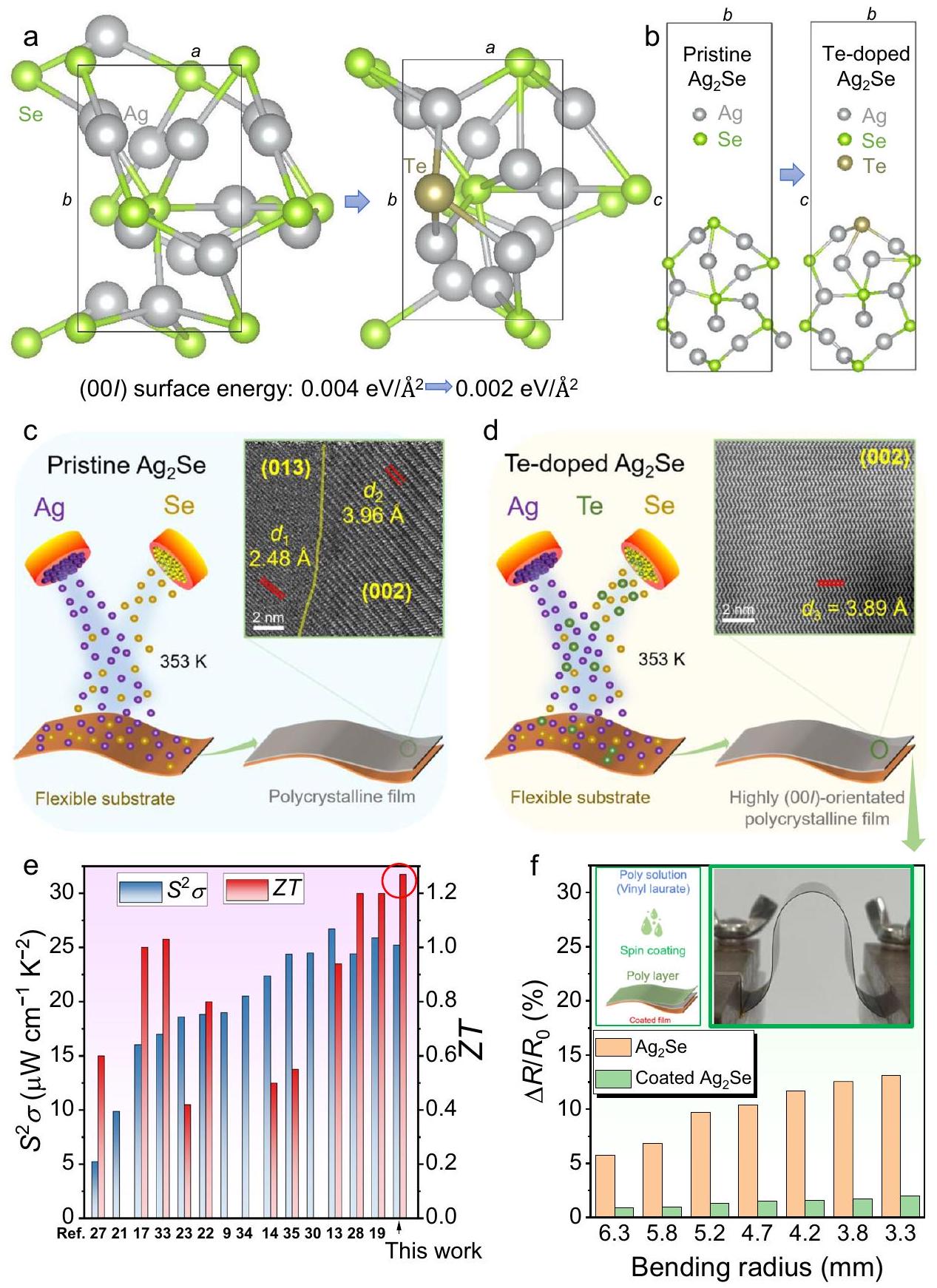
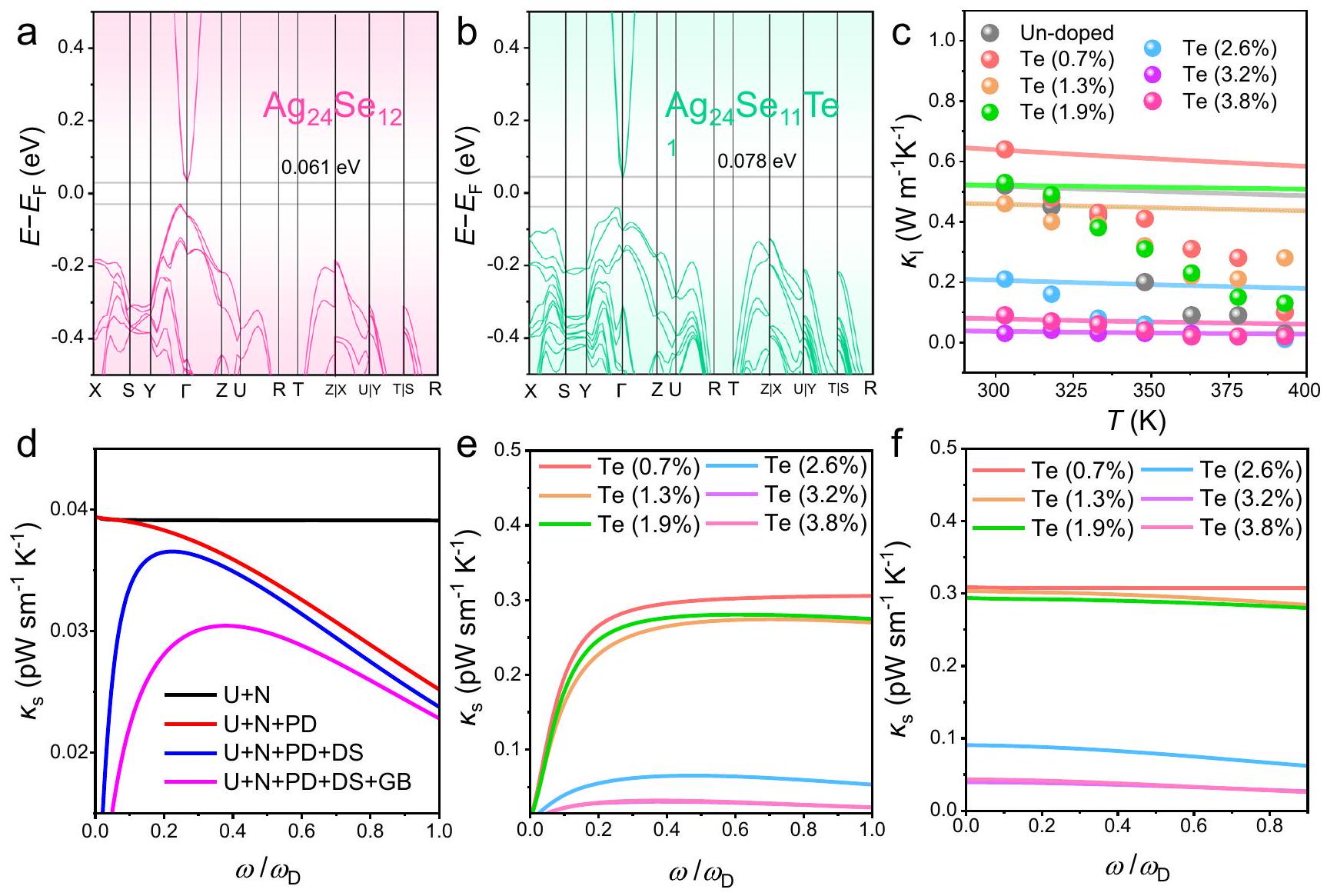
ويمكن أن يتبخر التيلوريوم من السطح خلال عملية المعالجة الحرارية. وبالتالي، تختلف التركيب الفعلي النهائي قليلاً عن التركيب الاسمي. لحسن الحظ، زادت محتويات التيلوريوم الفعلية في الأفلام أيضًا مع زيادة التركيب الاسمي لمحتويات التيلوريوم. وهذا يشير إلى أن التلويث بالتيلوريوم يمكن أن يكون ناجحًا.
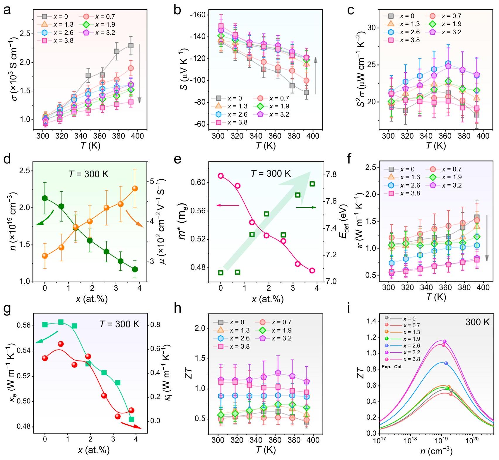
تم تحقيق ذلك، ولم يتم ملاحظة أي حد للتعاطي حتى الآن. وهذا يشير إلى أنه تحت ظروف تعاطي Te بتركيز منخفض، فإن تعاطي Te له معدل نجاح مرتفع. لتحليل تأثير تعاطي Te على الأداء الحراري الكهربائي للأفلام بشكل أفضل، استخدمنا التركيز الذري الفعلي لـ Te كمتغير، يُشار إليه بـ (بالنسبة المئوية) لتقييم
الجدول 1 | مقارنة بين التركيب الاسمي والتركيب الفعلي للمواد المصنعة المدعمة بالتيليوم الأفلام الرقيقة
التكوين الاسمي فضة (نسبة مئوية بالوزن) Se (نسبة مئوية بالوزن) Te (نسبة مئوية بالوزن)
66.8 ٣٣.٢ 0
66.4 ٣٢.٩ 0.7
66.0 ٣٢.٧ 1.3
65.6 ٣٢.٥ 1.9
65.2 ٣٢.٢ 2.6
٦٤.٧ ٣٢.١ 3.2
٦٤.٣ 31.9 3.8
تأثير تركيزات مختلفة من تشبع Te على الخصائص الكهروحرارية.
لفهم معلومات الطور للمواد المدعمة بالتيتانيوم المضاف إليها تمت دراسة حيود الأشعة السينية (XRD) للأفلام الرقيقة. الشكل 2أ يقارن أنماط XRD لـ أفلام رقيقة بتركيزات مختلفة من Te ، و مع يتراوح بين إلى . تتطابق جميع قمم الانكسار تمامًا مع الطور في درجة حرارة الغرفة لـ ، ولا توجد أي وجود لمرحلة الشوائب ضمن دقة فحص حيود الأشعة السينية. من الملحوظ أن العينة النقية الفيلم الرقيق بدون إضافة التيلوريوم يظهر ميزة بلورية متعددة نموذجية مع حبيبات غير متساوية، حيث تم ملاحظة العديد من قمم الانكسار المختلفة. على العكس، فإن فيلم رقيق مع Te –
الشكل 2 | معلومات عن الطور والبنية والتركيب للمواد المصنعة المدعمة بالتنجستن أفلام رقيقة. نماذج حيود الأشعة السينية (XRD) لـ أفلام رقيقة بتركيزات مختلفة من Te ، و مع يتراوح بين إلى . ب عوامل التوجه المحددة من الأفلام. ملفات القطب لـ أفلام رقيقة مع على طول الاتجاهات (c) (002) و(d) (013).
صور المجهر الإلكتروني الماسح (SEM) والتشتت الإلكتروني المرتد المقابل (EBSD) لـ أفلام رقيقة مع من العرض العلوي. تم توفير معلومات التوجيه للرجوع إليها. خرائط التحليل الطيفي للطاقة المشتتة (EDS) لـ أفلام رقيقة مع للتداخل والفردية وعناصر Te.
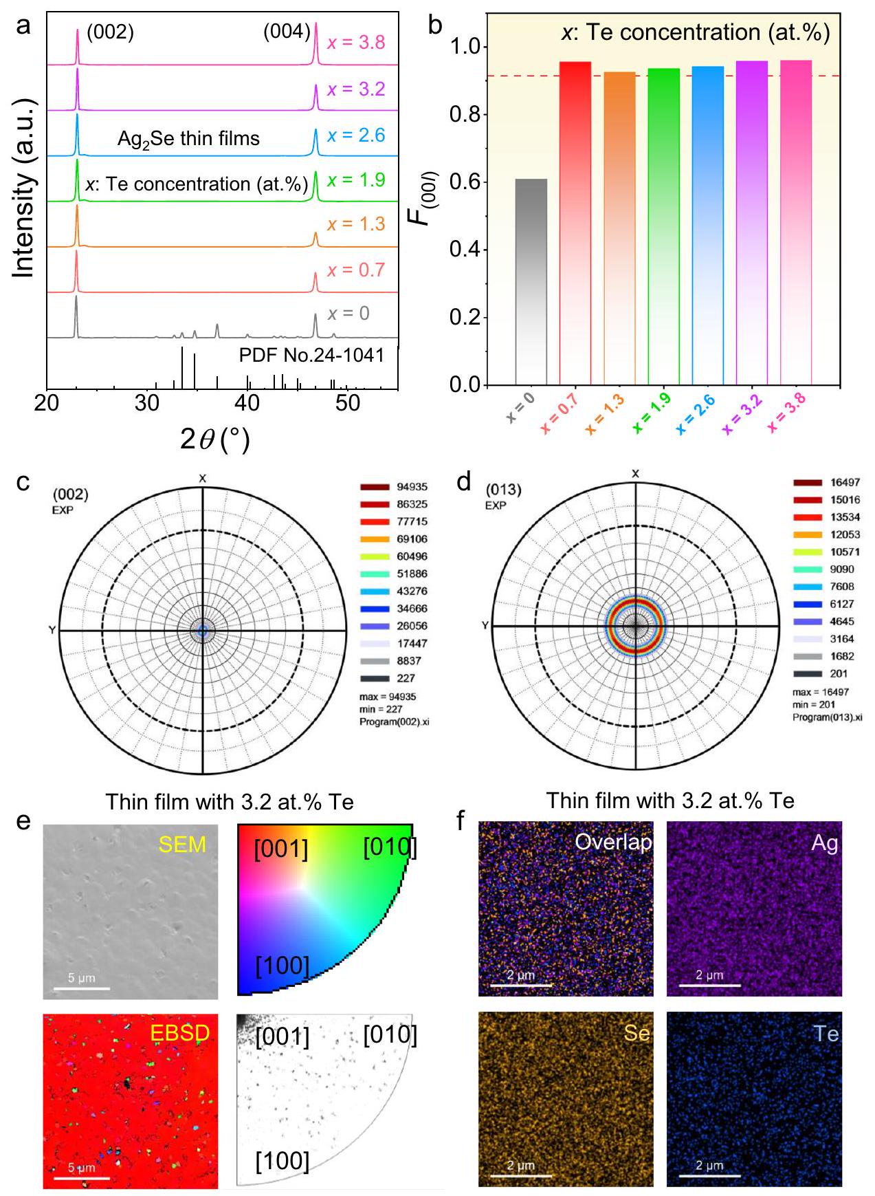
يظهر التلاعب ميزة موجهة بشكل نموذجي مع حبيبات متساوية الاتجاه حيث تم ملاحظة قمم (00l) فقط (قمم (002) و(004)). الشكل 2ب يقارن عوامل التوجه المحددة. أفلام. طرق حساب يمكن الإشارة إلى التفاصيل التجريبية. بعد إضافة التيلوريوم، تم تعزيز القيم بشكل ملحوظ إلى ، مما يشير إلى تحسينات في التوجه العام للأفلام الرقيقة. الشكل 2c و 2d يقارن بين ملفات القطب لـ أفلام رقيقة مع على طول الاتجاهين (002) و(013) على التوالي. الكثافات التي تنتمي إلى ( ) تصبح أكثر أهمية، مؤكدة بشكل مزدوج ( الميزة الموجهة نحو ( ) للفيلم الرقيق.
لفهم المعلومات الهيكلية والتركيبية للـ Te المضاف كما هو مصنّع تمت دراسة الأفلام الرقيقة، المجهر الإلكتروني الماسح (SEM)، حيود الإلكترونات المرتدة (EBSD)، وتحليل EDS. الشكل 2e يعرض صور SEM وEBSD لـ أفلام رقيقة تحتوي على 3.2% وزناً من Te من المنظور العلوي. تم توفير معلومات التوجه كمرجع. كما يتضح، فإن الفيلم الرقيق المُصنّع حديثًا مع تشويب Te يتمتع بسطح ناعم وكثيف نسبيًا دون وجود مسام كبيرة، مما يدل على جودة عالية للفيلم الرقيق. تشير نتائج EBSD إلى أن الفيلم الرقيق المُصنّع حديثًا يمتلك توجهاً ملحوظاً [001]، مما يؤكد خاصية التوجه العالي. تعرض الشكل 2f خرائط EDS لـ أفلام رقيقة تحتوي على 3.2٪ وزناً من التيلوريوم للتداخل والفردية ، وعناصر Te. جميع العناصر موزعة بشكل موحد دون تباين واضح في التركيب، مما يشير إلى أن التعديل متجانس على المستوى المجهري. نتائج TEM للعينة النقية تم توفير الفيلم الرقيق في الشكل التكميلية 2، الذي يظهر ميزة بولي كريستالية نموذجية مع حبوب غير متساوية، ونتائج SEM وEDS المقابلة لـ أفلام رقيقة مشوبة بتركيزات مختلفة من Te (باستثناء يمكن الرجوع إلى الأشكال التكميلية 3-7 للرجوع إليها.
لفهم المعلومات الميكرو/نانو هيكلية والتركيبية للمواد المصنعة حديثًا المدعمة بالتيلوريوم تمت دراسة خصائص الأفلام الرقيقة باستخدام مجهر المسح الإلكتروني الناقل المصحح للانحراف (Cs-STEM). تُظهر الصورة 3a صورة مجال مظلم دائري عالي الزاوية (HAADF) باستخدام المجهر الإلكتروني. فيلم رقيق يحتوي على 3.2٪ من التيلوريوم من منظور مقطع عرضي. تم إعداد العينة باستخدام تقنية شعاع الأيونات المركزة (FIB). التيلوريوم المخلوط تظهر الفيلم الرقيق جودة جيدة دون وجود مسام ظاهرة أو مرحلة شوائب ملحوظة من المقياس المجهري. سمك الفيلم الرقيق المُصنّع حديثًا متجانس نسبيًا. بالمقارنة مع العينة غير المُشوبة (الشكل التكميلي 2)، فإن اتجاه حبيباتها أكثر تجانسًا. يوضح الشكل 3b خرائط EDS للتداخل والفردية. ، وعناصر Te، على التوالي، مأخوذة من الشكل 3أ. جميع العناصر موزعة بشكل موحد، ولا يوجد تمييز ملحوظ بين العناصر. الشكل 3ج يظهر مسح خطي باستخدام EDS مأخوذ من الشكل 3أ. على طول اتجاه سمك الفيلم، لا يوجد تباين في توزيع العناصر، مما يؤكد أن التخصيب موحد بشكل استثنائي. الشكل 3د يظهر صورة Cs-STEM HAADF مأخوذة من الشكل 3أ. حتى في المنطقة القريبة من الركيزة المرنة (PI)، يحتفظ الفيلم المُعد حديثًا ببلورية ممتازة وتوجه دون وجود عيوب ملحوظة في هذه المنطقة. علاوة على ذلك، لا يوجد شق واضح بين الفيلم والركيزة، مما يدل على وجود التصاق قوي بينهما. الشكل 3هـ يظهر صورة Cs-STEM HAADF مكبرة مأخوذة من الشكل 3د. الإطار الداخلي يظهر نمط تحويل فورييه السريع (FFT) المقابل مع معلومات مفهرسة، مما يشير إلى أن الاتجاه المرئي هو يمكن أيضًا الإشارة إلى نمط FFT عالي الدقة المفهرس في الشكل التوضيحي الإضافي 8. كما يتضح، فإن الميكرومنطقة من الفيلم تظهر توجيهًا ممتازًا وبلورية. يوضح الشكل 3f خرائط الإجهاد المقابلة على طول اتجاهات مختلفة. ومن المثير للاهتمام أن خرائط الإجهاد تكشف عن إجهاد أكثر وضوحًا على طول الـ -الاتجاه، مما يشير إلى أن الضغوط تؤثر بشكل أساسي على -الاتجاه. من المحتمل أن يُعزى ذلك إلى تشويب التيلوريوم. تُظهر الصورة عالية الدقة Cs-STEM HAADF المأخوذة من الشكل 3e. تُظهر الصورة المرفقة بنية البلورة المخصبة بالتيلوريوم. للمرجع. الشكل 3h يظهر صورة HAADF مصفاة بتقنية Cs-STEM،
يظهر الفرق في التباين. السهم يشير إلى نقطة عيب محتملة من لأنه يظهر فرق تباين أعلى. الشكل 3i يظهر أيضًا ملف خط مأخوذ من الشكل 3g، مما يؤكد وجود عيب نقطي محتمل. تؤكد خرائط EDS المأخوذة من تكبير عالٍ أيضًا على العيب النقطي المحتمل لـ وتشير إلى أن هذه العيوب النقطية قد لا تكون موزعة بشكل موحد على النانو (الشكل التكميلي 9) لأن طريقة التبخر الحراري في الفراغ قد لا تقوم بدوبان Te بدقة على مواقع Se على المستوى الذري، وهو أمر مفهوم.
من حيث تأثير إضافة التيلوريوم على الأداء الحراري الكهربائي لـ الأفلام الرقيقة، قمنا بتقييم الخصائص الكهروحرارية لـ أفلام رقيقة بتركيزات مختلفة من Te ، ، و 3.8 أ. ). الشكل 4 أ-ج يظهر اعتماد درجة الحرارة وحدد . بشكل عام، مع زيادة الـ قيمة، تم تقليله و تم تحسينه، مما يؤدي إلى تحسين من عند 363 ك تم إدخال التيلوريوم في الفيلم الرقيق. لفهم التغيرات في ، و الشكل 4د يقارن القياسات -معتمد و في درجة حرارة الغرفة. من خلال زيادة الـ القيمة، يخ suppresses ولكن يعزز. التحسين في يستفيد من الهياكل الأكثر تجانسًا للأفلام الرقيقة مع عالية ( التوجهات، التي تساعد في الحفاظ على مستوى عالٍ القيم على الرغم من تم تقليله. لشرح الانخفاض نقوم بإجراء حسابات DFT من المبادئ الأولى. الشكل 5أ، ب يقارن بين الهياكل النطاقية المحسوبة لـ ( ) و المضاف إليه Te على التوالي، مما يشير إلى أن هو شبه موصل ضيق الفجوة بشكل نموذجي، سواء تم تشويهه بالتيتانيوم أو لا. ومن المثير للاهتمام أنه بعد تشويه التيتانيوم في مواقع السيلينيوم، زادت فجوة الطاقة قليلاً من 0.061 إلكترون فولت إلى 0.078 إلكترون فولت، مما يفسر التحسن. وانخفضت الشكل 4 e يقارن بين القيم المحسوبة الكتلة الفعالة المعتمدة على- وإمكان التشوه في درجة حرارة الغرفة بواسطة نموذج الشريط البارابوليكي الفردي (SPB). مع زيادة القيمة، تسقط ولكن يعزز. الانخفاض في يأتي من قمع نظرًا لعدم وجود مرحلة ثانوية واضحة لتوفير حدود مرحلة يمكن أن تحفز تأثير تصفية الطاقة . هذا يؤكد أيضًا أن الزيادة لا يأتي من تصفية الطاقة عند الواجهات. من حيث تحسينه يشير إلى أن قدرة التشوه للشبكة تصبح أكثر صعوبة بسبب إضافة التيلوريوم. نقوم أيضًا بمقارنة النتائج المحسوبة والتجريبية. كنتيجة لـ (الشكل التوضيحي 10). البيانات المحسوبة هي من نموذج SPB. كما لوحظ، القيم أعلى من تلك المبلغ عنها لـ بلورات مفردة ويمكن تحسينها تدريجياً من خلال زيادة تركيز تشويب Te لتحقيق الذروة في الفيلم الرقيق. الشكل 4 (و) يظهر قياس درجة الحرارة المعتمد على لـ أفلام رقيقة بتركيزات مختلفة من Te ، و . مع زيادة الـ القيمة، قد انخفض، مما يشير إلى أن إضافة التيلوريوم يمكن أن تساعد في تقليل النقل الحراري العام للفيلم الرقيق. الشكل 4 ج يقارن الاعتمادية على الموصلية الحرارية الإلكترونية والبلورية و ) في درجة حرارة الغرفة. الـ البيانات مأخوذة من المعادلة ، حيث هو رقم لورينز (الشكل التكميلي 11)، و . بشكل عام، مع زيادة الـ القيمة، كلا من و الـ انخفاض. الانخفاض في يأتي من قمع بينما تم إسقاط مشتق من زيادة شدة عيوب النقاط التي تشتت الفونونات بشكل فعال. يجب ملاحظة أنه عندما يكون المحتوى الذري من Te هو ، الـ الحصول عليه منخفض للغاية. ويرجع ذلك جزئيًا إلى أن قياسات الموصلية الحرارية للأفلام الرقيقة عادة ما تحتوي على هامش خطأ كبير. على الرغم من أن هناك طرقًا لقياس الموصلية في المستوى تم الإبلاغ عن أفلام رقيقة من البوليمر التكنولوجيا الحالية لاختبار في المستوى للفيلم الرقيق غير العضوي لم يصل بعد إلى النضج الكامل بالإضافة إلى ذلك، تظهر الحسابات باستخدام نموذج SPB أيضًا بعض الانحراف، ويختلف هذا الانحراف اعتمادًا على نظام المادة. تظهر الشكل 4 ح درجة الحرارة المعتمدة المحددة متميز قيمة 1.27 عند 363 كلفن، بالإضافة إلى ارتفاع من 1.15 في درجة حرارة الغرفة، كلاهما يحتل أعلى القيم بين القيم المبلغ عنها حتى الآن (الجدول التكميلي 1). الشكل 4i يقارن أيضًا بين القيم المحسوبة والتجريبية كنتيجة لـ . البيانات المحسوبة من نموذج SPB. كما يتضح، يمكن أن تكون القيمة
الشكل 3 | التوصيفات الميكرو/النانوية للـ فيلم رقيق مع عينة من عرض مقطع عرضي. تم إعداد العينة باستخدام تقنية شعاع الأيونات المركزة (FIB). خرائط EDS للتداخل والفردي ، وعناصر Te المأخوذة من (أ). ج مسح خط EDS مأخوذ من (أ). د صورة HAADF من TEM الماسح المصحح للانحراف الكروي (Cs-STEM) مأخوذة من (أ). هـ صورة HAADF من Cs-STEM مكبرة مأخوذة من (د). يظهر الإطار الداخلي تحويل فورييه السريع المقابل
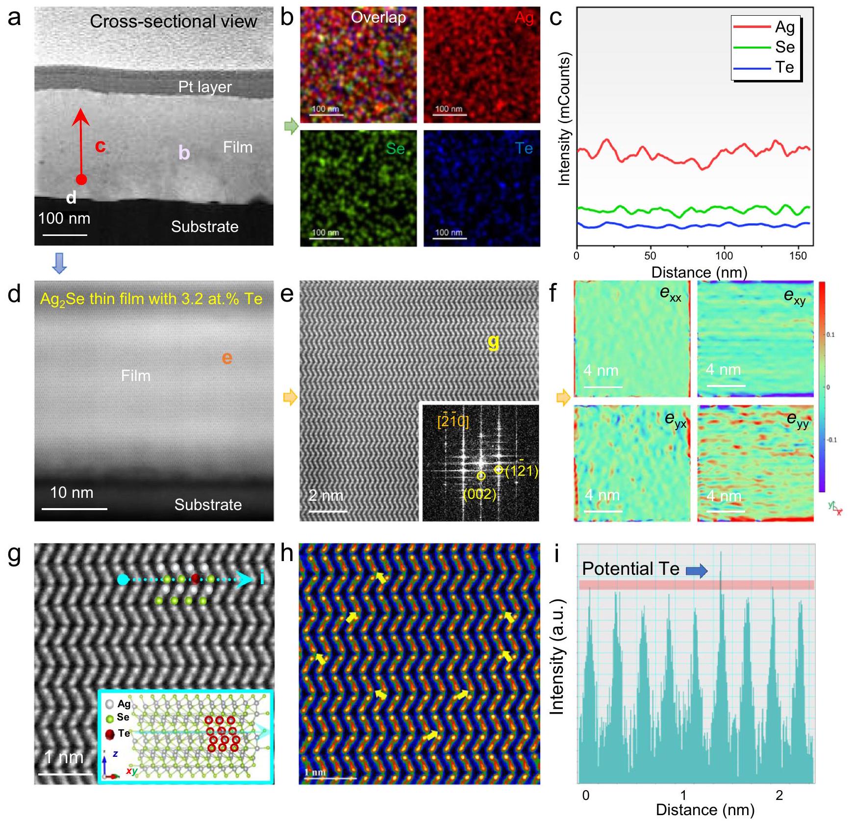
نمط تحويل فورييه السريع (FFT) مع معلومات مفهرسة. خرائط الإجهاد المقابلة على طول اتجاهات مختلفة. صورة Cs-STEM HAADF عالية الدقة مأخوذة من (e). يظهر الإطار الصغير بنية البلورة للمواد المدعمة بالتيليوريوم. للمرجع. صورة HAADF المفلترة لـ CsSTEM لإظهار فرق التباين. السهم يشير إلى نقطة عيب محتملة. . ملف الخط المأخوذ من (g) لإظهار نقطة العيب المحتملة .
تم تحسينه تدريجياً من خلال زيادة تركيز الشوائب من عنصر التيلوريوم لتحقيق الذروة في الفيلم الرقيق.
لتفسير تأثير تشتت الفونونات على تقليل، يتم اعتماد نموذج كالاواي. انخفاض هو المسؤول بشكل رئيسي عن الانخفاض في اعتمادًا على ظواهر تشتت الفونونات المختلفة. يتم دراسة نموذج ديباي كالاوي لتوضيح مصدر الانخفاض في :
هنا ، و تمثل سرعة الصوت، درجة حرارة ديباي، تردد الفونون المخفض ( )، ووقت الاسترخاء الكلي للفونونات. من المRemarkably، فإن التشتت القوي للفونونات ينشأ عن عناصر السبائك/العيوب الداخلية والحبيبات التي تتحمل المسؤولية الرئيسية عن الانخفاض في للعينات المضافة إليها التيتانيوم. هنا، تم الحصول على تظهر منحنيات البيانات (الخطوط الصلبة) عدم توافق مع النتائج التجريبية لتركيزات تشويب التيلوريوم أقل من (الشكل 5ج) عند درجات حرارة مرتفعة، متماشياً مع اتجاه (حيث هو الموصلية الحرارية ثنائية القطب) كدالة لـ (الشكل التكميلي 15أ). من المحتمل أن تكون هذه التناقضات ناتجة عن تأثير الانتشار الثنائي القطب على الموصلية الحرارية عند درجات الحرارة العالية (الشكل التكميلي 15ب).
الشكل 4 | الخصائص الكهروحرارية لـ أفلام رقيقة بتركيزات مختلفة من Te ، و التوصيل الكهربائي المعتمد على درجة الحرارة (أ) معامل سيبيك ، و (ج) محدد . تم قياسه تركيز الحامل المعتمد على “-dependent” والتنقل في درجة حرارة الغرفة. تم حسابه الكتلة الفعالة المعتمدة على وإمكان التشوه
عند درجة حرارة الغرفة بواسطة نموذج الشريط البارابوليكي الفردي (SPB). الموصلية الحرارية المعتمدة على درجة الحرارة (f) التوصيلات الحرارية الإلكترونية والبلورية المعتمدة على و ) في درجة حرارة الغرفة. معتمد على درجة الحرارة . مقارنة بين القيم المحسوبة والتجريبية كنتيجة لـ البيانات المحسوبة هي من نموذج SPB.
كما هو موضح في الشكل 5d، قد يؤدي تشتت الفونونات من حدود الحبيبات، والعيوب النقطية، و/أو العيوب البلورية إلى تقليل نقل الفونونات بشكل كبير. في الوقت نفسه، تحدد المنحنيات/القيم المحسوبة المساهمة الرئيسية لتشتت الفونونات من العيوب النقطية/الشوائب وحدود الحبيبات (الشكل 5e، f). تتوفر تفاصيل حول الحسابات والمعلمات المستخدمة في نموذج ديباي-كالواي لجميع العينات المدروسة المضافة في المعلومات التكميلية.
بعد تناول المنشطات، على الرغم من أن هيكل الـ تم تحسين الفيلم في التوحيد (الاتجاه العام يميل إلى تفضيل ( )), هذا لا يعني بالضرورة أن مرونته قد تحسنت بشكل كبير. في الواقع، بعد إضافة Te، تحسنت المرونة بشكل طفيف فقط (الشكل التوضيحي 12). بالإضافة إلى ذلك، فإن الزيادة في الذي تسببه مادة الدوبينغ قد يؤدي إلى تقليل تباين الشبكة، مما قد ينتج عنه زيادة في صلابة الفيلم. لذلك، لتعزيز القيمة العملية للـ
تم الحصول على فيلم رقيق عالي الأداء، ولكن هناك حاجة إلى تحسينات كبيرة في مرونته. في هذا العمل، قمنا بتصميم طبقة واقية مصنوعة من مركبات البوليمر العضوي بولي (فينيل لورات) و -ميثيل بيروليدون)، الذي يتم تطبيقه على سطح الفيلم باستخدام عملية الطلاء بالدوران. الشكل 6أ، ب يقارن القياسات من أفلام رقيقة تحتوي على 3.2% وزناً من التيلوريوم بدون وبتغطيات قائمة على الفينيل لورات عند أشعة انحناء ودورات انحناء مختلفة. تُظهر الصورة في الزاوية في الشكل 6ب صورة للفيلم الرقيق المرن. من أجل مقارنة أفضل، تم تعديل نطاقات المحور العمودي في كلا الرسمين لتكون متسقة. من الواضح أنه بعد تغطية المركبات البوليمرية العضوية، تم تحسين المرونة العامة للفيلم الرقيق بشكل كبير. بعد 1000 دورة انحناء مع نصف قطر انحناء يبلغ 6.3 مم، فإن فقدان الأداء هو فقط تعتبر هذه المرونة المتميزة تنافسية للغاية مقارنةً بالأعمال المبلغ عنها التي تعتمد على الأفلام الرقيقة غير العضوية للحرارة الكهربائية (الجدول 2). الشكل التكميلي 13 يوفر أيضًا
الشكل 5 | نتائج الحسابات لـ مُشَبَّع بـ الأفلام الرقيقة. الهياكل النطاقية المحسوبة لـ (أ) و (ب) المضاف إليه Te . (ج) مقاس مقارنةً مع المحسوب كنتيجة لدرجة الحرارة. الطيف المستمد نظريًا لـ أفلام رقيقة بتركيزات مختلفة من Te ، ، و )، مع تشتتات فونون مختلفة. هنا التشتت
يأتي من عملية أومكلاب والفونون-فونون العادية العيوب النقطية (PD)، حدود الحبوب (GB)، والانزلاقات (DS). تأثير تشتت العيوب النقطية و(ف) اعتماد حجم الحبوب على التقليل كنتيجة لمحتوى Te.
مقاس المغطاة أفلام رقيقة تحتوي على 3.2٪ وزناً من التيلوريوم عند انحناءات مختلفة وحرارة عند من خلال فترات مختلفة لثني 1000 مرة، مما يؤكد المرونة العالية عند درجات حرارة أعلى.
استنادًا إلى هذا الفيلم الرقيق المغلف الجديد، قمنا بتصميم F-TED سهل لتأكيد عمليته. لتعزيز أداء F-TED بشكل أكبر، تم تقليل مقاومة الاتصال. بين الفيلم الرقيق والأقطاب الكهربائية أمر حاسم. لذلك، نحتاج إلى اختيار مواد أقطاب مناسبة لتتناسب مع مادة الفيلم الرقيق، وهو ما نادراً ما تم الإبلاغ عنه في تصاميم F-TEDs المرنة في الماضي. الشكل 6 ج يظهر القياسات بين فيلم رقيق مع ومواد أقطاب كهربائية مختلفة بما في ذلك ، وCu. مبدأ القياس موضح في الشكل التوضيحي 14 للرجوع إليه. اخترنا Cu كمادة محتملة للإلكترود تمتلك أقل . بناءً على ذلك، قمنا بتجميع F-TED وقمنا بتقييم أدائه. الخصائص الرئيسية للحرارة الكهربائية عند درجة حرارة الغرفة لكل من و مقدمة في الجدول 3. الشكل 6d يقارن بين الفولتية المفتوحة المقاسة وقوى الخرج للجهاز كدالة لتيار التحميل عند مستويات مختلفة س، ويقارن الشكل 6e كثافات القدرة الناتجة المحددة عند مختلف . يظهر الشكل الداخلي صورة لجهاز مرن يتكون من زوج واحد من فيلم رقيق مع كقدم من النوع n و فيلم رقيق كقدم من النوع p. من المRemarkably، جهد مفتوح الدائرة مرتفع يبلغ 6 مللي فولت، وقوة خرج كبيرة تبلغ 65 نانو وات، وكثافة طاقة تنافسية من يمكن تحقيقه في الوقت نفسه في من . المقارنة
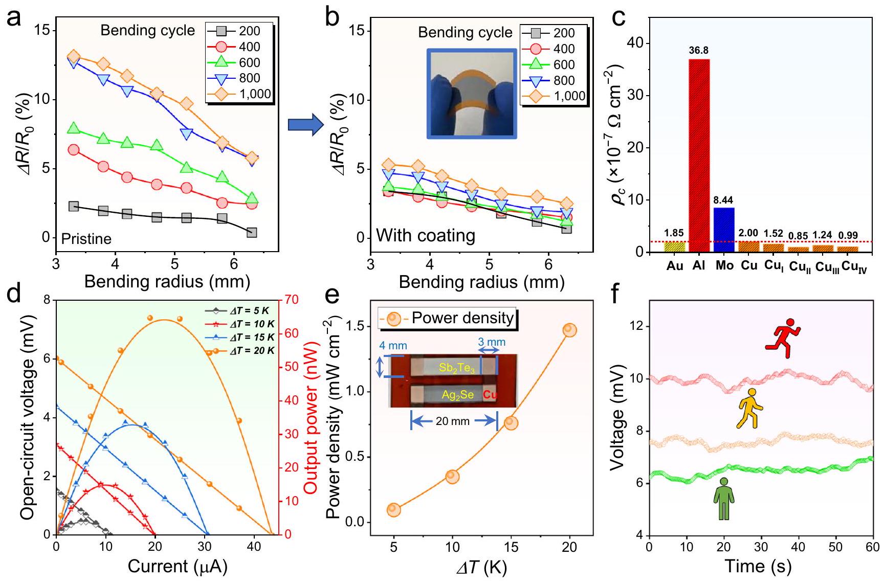
تُقدم النتائج في الجدول التكميلي 3. الشكل 6f يقارن الجهد المقاس عند ارتداء F-TED مع خمسة أرجل p-n أثناء الجلوس والمشي والجري كدالة للوقت. تم الحصول على أقصى جهد عند ارتداء الجهاز أثناء الجري. وذلك لأن أثناء الجري، يكون هناك تبديد أفضل للحرارة على جانب الجهاز المعرض للهواء، مما يساعد على الحفاظ على تدرج حرارة أكبر وبالتالي يسمح للجهاز بالعمل بشكل أفضل.
باختصار، يُبلغ هذا العمل عن رقم قياسي مرتفع من 1.27 عند 363 كلفن في الحالة متعددة البلورات فيلم رقيق قائم على ت. تشير الحسابات النظرية إلى أن إضافة التيلوريوم يمكن أن تقلل من طاقة التكوين لـ ( ) السطح، مما يؤدي إلى قوة ( ) التوجه عبر الفيلم لتعزيز تجانسه وبالتالي حركة الحاملين. علاوة على ذلك، فإن إضافة التيلوريوم توسع فجوة الطاقة قليلاً وتؤدي إلى زيادة معامل سيبيك وعامل قدرة مرتفع عن طريق تحسين تركيز الحاملات. إن إضافة التيلوريوم في مواقع السيلينيوم أيضًا يقدم عيوب نقطية تشتت الفونونات بشكل فعال، مما يقلل من الموصلية الحرارية إلى . بعد 1000 دورة انحناء مع نصف قطر انحناء يبلغ 6.3 مم، يظهر الفيلم فقط فقدان الأداء بسبب تغليف طبقة واقية مصنوعة من مركبات قائمة على البوليمر العضوي على سطح الفيلم، مما يشير إلى تحسين كبير في المرونة العامة. أخيرًا، تم تجميع الجهاز الحراري المرن باستخدام زوج من النوع p ونوع n تصل الأفلام إلى جهد دائرة مفتوحة قدره 6 مللي فولت، وقوة خرج قدرها 65 نانو وات، وكثافة طاقة قدرها تحت فرق درجة حرارة قدره 20 كلفن. تشير هذه الدراسة إلى أن إضافة التيلوريوم يمكن أن تؤثر بشكل كبير
الشكل 6 | مرونة المواد المدعمة بالتيتانيوم الأفلام الرقيقة وأداء أجهزتها. تم قياس من أفلام رقيقة مع بدون و (ب) مع طلاء قائم على الفينيل لورات عند أشعة انحناء مختلفة ودورات انحناء. الصورة المصغرة في (ب) تظهر صورة للفيلم الرقيق المرن. المقاومة النوعية المقاسة للاتصال بين المغلف فيلم رقيق يحتوي على 3.2٪ وزناً من التيلوريوم ومواد أقطاب مختلفة. د تم قياس الفولتية المفتوحة والقدرات الناتجة للجهاز كدالة لـ
تحميل الحالية عند اختلافات درجات حرارة مختلفة ( ). تم تحديد كثافات القدرة الناتجة عند مستويات مختلفة . يظهر الشكل الداخلي صورة لجهاز مرن يتكون من زوج واحد من المغلفين فيلم رقيق مع كقدم من النوع n ومغطاة فيلم رقيق كطرف من النوع p. جهد ارتداء الجهاز المصنوع كما هو للجلوس والمشي والجري كدالة للوقت.
تحسين الإمكانيات الكهروحرارية لـ أفلام في تطبيق توليد الطاقة القابلة للارتداء.

طرق

تصنيع الأفلام الرقيقة والأجهزة

المرن تم تصنيع الأفلام الرقيقة على ركائز PI بواسطة طريقة التبخر الحراري الفراغي عند درجات حرارة مختلفة.
الجدول 2 | مقارنة المرونة بين فيلم رقيق مع والأعمال المبلغ عنها
المواد دورة الانحناء مرجع
1000 ٥ حوالي 20% 42
٢٠٠٠ ٧ حوالي 30% 43
10 ٤ و ٦٠ حوالي 21% ٤٤
أنابيب الكربون الأحادية الجدار ٦٠٠ ٤ حوالي 4% ٤٥
1000 ٥ حوالي 20% ٤٦
100 10 حوالي 6% ٤٧
1000 10 حوالي 2.5% ٤٨
المخلوط بالفضة ٢٠٠٠ <6 <4% ٦
مُشبع بالتيتانيوم 1000 ~6.3 حوالي 2.5% هذا العمل
تشمل البيانات دورات الانحناء ونصف قطر الانحناء وزيادة المقاومة العادية لأفلام غير عضوية مرنة متنوعة. في هذا السياق، تشير CF إلى ألياف السليلوز.
بعد ذلك، واحد تم تصنيع جهاز حراري كهربائي مع قطب نحاسي على ركيزة من البولي إيميد. ثم تم استخدام مادة طلاء عضوية، بولي فينيل لوريت، لتعزيز مرونة الجهاز المصنع. الأفلام الرقيقة. يمكن العثور على التفاصيل التجريبية في المعلومات التكميلية.

توصيفات وتقييم أداء المواد الكهروحرارية

يمكن العثور على التفاصيل في المعلومات التكميلية.

الحساب النظري

تم إجراء حسابات المبادئ الأساسية ونموذج بارابوليك الفردي (SPB) لفهم أداء نقل الحاملات. تم التحقيق في نموذج ديباي-كالواي لتوضيح مصدر تقليل الموصلية الحرارية. يمكن العثور على مزيد من التفاصيل في المعلومات التكميلية.
الجدول 3 | الخصائص الحرارية الكهربائية لـ فيلم رقيق مع كقدم من النوع n و فيلم رقيق كطرف نوع p في الجهاز الحراري المرن
المواد نوع
سمك
فيلم رقيق مع
3.2٪ تيلوريوم
-146.0 990.0 21.1
فيلم رقيق 143.2 ٥١٣.٦ 10.5

توفر البيانات

البيانات التي تم توليدها في هذه الدراسة متاحة في ملف المعلومات التكميلية/بيانات المصدر. يتم توفير بيانات المصدر مع هذه الورقة.

References

  1. Liu, R., Wang, Z. L., Fukuda, K. & Someya, T. Flexible self-charging power sources. Nat. Rev. Mater. 7, 870-886 (2022).
  2. Zhang, L., Shi, X.-L., Yang, Y.-L. & Chen, Z.-G. Flexible thermoelectric materials and devices: From materials to applications. Mater. Today 46, 62-108 (2021).
  3. Yang, Q. et al. Flexible thermoelectrics based on ductile semiconductors. Science 377, 854-858 (2022).
  4. Xiao, Y. & Zhao, L.-D. Seeking new, highly effective thermoelectrics. Science 367, 1196 (2020).
  5. Jiang, B. et al. High-entropy-stabilized chalcogenides with high thermoelectric performance. Science 371, 830-834 (2021).
  6. Zheng, Z.-H. et al. Harvesting waste heat with flexible thermoelectric thin film. Nat. Sustain. 6, 180-191 (2023).
  7. Wei, T.-R. et al. Ag2Q-Based (Q = S, Se, Te) silver chalcogenide thermoelectric materials.Adv. Mater 35, 2110236 (2023).
  8. Zhu, M., Shi, X.-L., Wu, H., Liu, Q. & Chen, Z.-G. Advances in -based thermoelectrics for wearable electronics: Progress and perspective. Chem. Eng. J. 475, 146194 (2023).
  9. Hou, S. et al. High performance wearable thermoelectric generators using films with large carrier mobility. Nano Energy 87, 106223 (2021).
  10. Hou, S. et al. High-performance, thin-film thermoelectric generator with self-healing ability for body-heat harvesting. Cell Rep. Phys. Sci. 3, 101146 (2022).
  11. Xin, C. et al. Solution-processed flexible n-Type S-doped thermoelectric generators for near-ambient-temperature energy harvest. Mater. Today Energy 33, 101266 (2023).
  12. Lu, Y., Liu, Y., Li, Y. & Cai, K. The influence of Ga doping on preparation and thermoelectric properties of flexible films. Compos. Commun. 27, 100895 (2021).
  13. Li, Y. et al. Exceptionally high power factor Polypyrrole composite films for flexible thermoelectric generators. Adv. Funct. Mater. 32, 2106902 (2022).
  14. Lu, Y. et al. Ultrahigh power factor and flexible silver selenide-based composite film for thermoelectric devices. Energy Environ. Sci. 13, 1240-1249 (2020).
  15. Hu, Q.-X. et al. SWCNTs/ film with superior bending resistance and enhanced thermoelectric performance via in situ compositing. Chem. Eng. J. 457, 141024 (2023).
  16. Jiang, C. et al. Ultrahigh performance polyvinylpyrrolidone/ composite thermoelectric film for flexible energy harvesting. Nano Energy 80, 105488 (2021).
  17. Lu, Y. et al. Ultrahigh performance PEDOT/ composite film for wearable thermoelectric power generators. Mater. Today Phys. 14, 100223 (2020).
  18. Park, D., Ju, H. & Kim, J. Enhanced thermoelectric properties of flexible N-type nanowire/polyvinylidene fluoride composite films synthesized via solution mixing. J. Ind. Eng. Chem. 93, 333-338 (2021).
  19. Lei, Y. et al. Microstructurally tailored thin films towards commercial flexible thermoelectrics. Adv. Mater. 34, 2104786 (2021).
  20. Zheng, Z.-H. et al. Significantly (OOl)-textured thin films with excellent thermoelectric performance for flexible power applications. J. Mater. Chem. A 10, 21603-21610 (2022).
  21. Ding, Y. et al. High performance n-Type film on nylon membrane for flexible thermoelectric power generator. Nat. Commun. 10, 841 (2019).
  22. Jiang, C. et al. Ultrahigh performance of -Type films for flexible thermoelectric power generators. ACS Appl. Mater. Interfaces 12, 9646-9655 (2020).
  23. Gao, Q. et al. High power factor composite films for flexible thermoelectric generators. ACS Appl. Mater. Interfaces 13, 14327-14333 (2021).
  24. Wang, Z. et al. High performance composite films for wearable thermoelectric power generators. Mater. Today Phys. 21, 100553 (2021).
  25. Geng, J. et al. High power factor n-Type hybrid film for flexible thermoelectric generator. J. Phys. D. Appl. Phys. 54, 434004 (2021).
  26. Mallick, M. M., Franke, L., Rösch, A. G. & Lemmer, U. Shape-versatile 3D thermoelectric generators by additive manufacturing. ACS Energy Lett. 6, 85-91 (2021).
  27. Mallick, M. M. et al. High-performance Ag-Se-Based n-Type printed thermoelectric materials for high power density folded generators. ACS Appl. Mater. Interfaces 12, 19655-19663 (2020).
  28. Perez-Taborda, J. A., Caballero-Calero, O., Vera-Londono, L., Briones, F. & Martin-Gonzalez, M. High thermoelectric zT in n-Type silver selenide films at room temperature. Adv. Energy Mater. 8, 1702024 (2018).
  29. Jindal, S., Singh, S., Saini, G. S. S. & Tripathi, S. K. Optimization of thermoelectric power factor of (013)-oriented films via thermal annealing. Mater. Res. Bull. 145, 111525 (2022).
  30. Gao, J. et al. Thermoelectric flexible silver selenide films: compositional and length optimization. iScience 23, 100753 (2020).
  31. Lu, Y. et al. Staggered-layer-boosted flexible films with high thermoelectric performance. Nat. Nano 18, 1281-1288 (2023).
  32. Karato, S.-I. An introduction to the rheology of Solid Earth. Vol. 463. 2008: Cambridge University Press Cambridge, UK.
  33. Mallick, M. M. et al. New frontier in printed thermoelectrics: formation of Se through thermally stimulated dissociative adsorption leads to high ZT. J. Mater. Chem. A 8, 16366-16375 (2020).
  34. Zheng, Z.-H. et al. Achieving ultrahigh power factor in n -type thin films by carrier engineering. Mater. Today Energy 24, 100933 (2022).
  35. Li, X. et al. Exceptional power factor of flexible Ag/Ag2Se thermoelectric composite films. Chem. Eng. J. 434, 134739 (2022).
  36. Almufarij, S. R. et al. Enhanced the thermoelectric power factor of n-type thin film via energy filtering effect. Inorg. Chem. Commun. 157, 111439 (2023).
  37. Lin, S. et al. Revealing the promising near-room-temperature thermoelectric performance in single crystals. J. Materiomics 9, 754-761 (2023).
  38. Weathers, A. et al. Significant electronic thermal transport in the conducting polymer Poly(3,4-ethylenedioxythiophene). Adv. Mater. 27, 2101-2106 (2015).
  39. Li, D. et al. Ce-filled skutterudite thin films with record-high figure of merit and device performance. Adv. Energy Mater. 13, 2301525 (2023).
  40. Zhu, J. et al. Restructured single parabolic band model for quick analysis in thermoelectricity. NPJ Comput. Mater. 7, 116 (2021).
  41. Jabar, B. et al. Enhanced power factor and thermoelectric performance for n-type based composites incorporated with 3D topological insulator nanoinclusions. Nano Energy 80, 105512 (2021).
  42. Shang, H. et al. High-performance Ag-Modified films for the flexible thermoelectric generator. ACS Appl. Mater. Interfaces 12, 7358-7365 (2020).
  43. Kong, D., Zhu, W., Guo, Z. & Deng, Y. High-performance flexible films based wearable thermoelectric generator for energy harvesting. Energy 175, 292-299 (2019).
  44. Cao, Z., Tudor, M. J., Torah, R. N. & Beeby, S. P. Screen printable flexible BiTe-SbTe-based composite thermoelectric materials on textiles for wearable applications. IEEE T. Electron Dev. 63, 4024-4030 (2016).
  45. Li, Y. et al. A flexible and infrared-transparent -carbon nanotube thermoelectric hybrid for both active and passive cooling. ACS Appl. Electron. Mater. 2, 3008-3016 (2020).
  46. Shang, H. et al. -based films for flexible thermoelectric devices. J. Mater. Chem. A 8, 4552-4561 (2020).
  47. Jin, Q. et al. Cellulose fiber-based hierarchical porous bismuth telluride for high-performance flexible and tailorable thermoelectrics. ACS Appl. Mater. Interfaces 10, 1743-1751 (2018).
  48. Varghese, T. et al. Flexible thermoelectric devices of ultrahigh power factor by scalable printing and interface engineering. Adv. Funct. Mater. 30, 1905796 (2020).
  49. Cao, T., Shi, X.-L. & Chen, Z.-G. Advances in the design and assembly of flexible thermoelectric device. Prog. Mater. Sci. 131, 101003 (2023).

شكر وتقدير

تم دعم هذا العمل من قبل المؤسسة الوطنية للعلوم الطبيعية في الصين (رقم 62274112)، ومؤسسة غوانغدونغ للبحث الأساسي والبحث التطبيقي (2022A1515010929)، ومشروع خطة العلوم والتكنولوجيا في شنتشن (JCYJ2O220531103601003). تشكر ZGC على الدعم المالي من مجلس أبحاث أستراليا، وبرنامج بناء القدرات في جامعة كوينزلاند للتكنولوجيا، وتقر بالبنية التحتية الوطنية للحوسبة، المدعومة من الحكومة الأسترالية، لتوفير الموارد والخدمات الحاسوبية. المؤلفون ممتنون للمساعدة في ملاحظة STEM-HAADF التي تم تلقيها من مركز المجهر الإلكتروني في جامعة شنتشن. تم تمكين هذا العمل من خلال استخدام المرافق البحثية التحليلية المركزية التي تستضيفها معهد البيئات المستقبلية في جامعة كوينزلاند للتكنولوجيا.

مساهمات المؤلفين

دي. واي. وإكس.-إل. إس. ساهموا بالتساوي في هذا العمل. زي.-جي. سي. وزي. إتش. زي. أشرفوا على المشروع وابتكروا الفكرة. دي. واي. وإكس.-إل. إس. صمموا التجارب وكتبوا المخطوطة. دي. واي. نفذ عملية تخليق المواد. إم. إل. وإكس.-إل. إس. وو. إل. وإتش. إم. وإكس. زي. قاموا بالعمل النظري. إم. إن. وأي. إم. وإس. سي. وي. سي. ول. إف. وجي.-إكس. إل. وبي. إف. قاموا بتقييم الأداء الحراري الكهربائي. جميع المؤلفين ناقشوا النتائج.
وقاموا بالتعليق على المخطوطة. جميع المؤلفين قد وافقوا على النسخة النهائية من المخطوطة.

المصالح المتنافسة

يعلن المؤلفون عدم وجود مصالح متنافسة.

معلومات إضافية

معلومات إضافية النسخة الإلكترونية تحتوي على
المواد التكميلية متاحة على
https://doi.org/10.1038/s41467-024-45092-7.
يجب توجيه المراسلات والطلبات للحصول على المواد إلى زوانغهاو تشنغ أو زهي-غانغ تشين.
معلومات مراجعة الأقران تشكر مجلة Nature Communications سوبرى بينيتسونتون، والمراجعين المجهولين الآخرين على مساهمتهم في مراجعة هذا العمل. يتوفر ملف مراجعة الأقران.
معلومات إعادة الطباعة والتصاريح متاحة على
http://www.nature.com/reprints
ملاحظة الناشر: تظل شركة سبرينجر ناتشر محايدة فيما يتعلق بالمطالبات القضائية في الخرائط المنشورة والانتماءات المؤسسية.
الوصول المفتوح هذه المقالة مرخصة بموجب رخصة المشاع الإبداعي النسب 4.0 الدولية، التي تسمح بالاستخدام والمشاركة والتكيف والتوزيع وإعادة الإنتاج بأي وسيلة أو صيغة، طالما أنك تعطي الائتمان المناسب للمؤلفين الأصليين والمصدر، وتوفر رابطًا لرخصة المشاع الإبداعي، وتوضح إذا ما تم إجراء تغييرات. الصور أو المواد الأخرى من طرف ثالث في هذه المقالة مشمولة في رخصة المشاع الإبداعي الخاصة بالمقالة، ما لم يُشار إلى خلاف ذلك في سطر الائتمان للمواد. إذا لم تكن المادة مشمولة في رخصة المشاع الإبداعي الخاصة بالمقالة وكان استخدامك المقصود غير مسموح به بموجب اللوائح القانونية أو يتجاوز الاستخدام المسموح به، فستحتاج إلى الحصول على إذن مباشرة من صاحب حقوق الطبع والنشر. لعرض نسخة من هذه الرخصة، قم بزيارةhttp://creativecommons.org/رخصة/بواسطة/4.0/.
© المؤلف(ون) 2024

  1. مختبر شنتشن الرئيسي للأفلام الرقيقة المتقدمة وتطبيقاتها، المختبر الرئيسي للأجهزة البصرية الإلكترونية والأنظمة التابعة لوزارة التعليم ومقاطعة قوانغدونغ، كلية الفيزياء والهندسة البصرية الإلكترونية، جامعة شنتشن، شنتشن، قوانغدونغ 518060، الصين. جامعة رين، CNRS، ISCR (معهد العلوم الكيميائية في رين) UMR 6226، رين F-35000، فرنسا. مدرسة الكيمياء والفيزياء، مركز أبحاث ARC في توليد الطاقة بدون انبعاثات لتحقيق الحياد الكربوني، ومركز علوم المواد، جامعة كوينزلاند للتكنولوجيا، بريسبان، كوينزلاند 4001، أستراليا. معهد أستراليا للهندسة الحيوية والتكنولوجيا النانوية، جامعة كوينزلاند، بريسبان، كوينزلاند 4072، أستراليا. ساهم هؤلاء المؤلفون بالتساوي: دونغ يانغ، شياو-لي شي. البريد الإلكتروني:zhengzh@szu.edu.cn; zhigang.chen@qut.edu.au

Journal: Nature Communications, Volume: 15, Issue: 1
DOI: https://doi.org/10.1038/s41467-024-45092-7
PMID: https://pubmed.ncbi.nlm.nih.gov/38296942
Publication Date: 2024-01-31

Flexible power generators by thin films with record-high thermoelectric performance

Received: 2 November 2023
Accepted: 15 January 2024
Published online: 31 January 2024
(A) Check for updates

Dong Yang , Xiao-Lei Shi , Meng , Mohammad Nisar , Adil Mansoor , Shuo Chen , Yuexing Chen © , Fu Li (1) , Hongli Ma , Guang Xing Liang , Xianghua Zhang ², Weidi Liu (B , Ping Fan (B , Zhuanghao Zheng (B Zhi-Gang Chen (1)

Abstract

Exploring new near-room-temperature thermoelectric materials is significant for replacing current high-cost . This study highlights the potential of for wearable thermoelectric electronics, addressing the trade-off between performance and flexibility. A record-high of 1.27 at 363 K is achieved in -based thin films with Te doping on Se sites, realized by a new concept of doping-induced orientation engineering. We reveal that Te-doping enhances film uniformity and ( )-orientation and in turn carrier mobility by reducing the ( 00 l) formation energy, confirmed by solid computational and experimental evidence. The doping simultaneously widens the bandgap, resulting in improved Seebeck coefficients and high power factors, and introduces point defects to effectively reduce the lattice thermal conductivity. A protective organic-polymer-based composite layer enhances film flexibility, and a rationally designed flexible thermoelectric device achieves an output power density of for wearable power generation under a 20 K temperature difference.

With the increasing popularity of smart wearable electronic devices such as wireless headphones, smart glasses, and smartwatches, traditional battery power sources have become inadequate to meet the demand for long-term use . There is an urgent need in the market to develop sustainable power supply technology. Among the various emerging power generation methods, flexible thermoelectric devices (F-TEDs) that can directly convert temperature differences between the human body and the external environment into electricity, have gained significant attention . F-TEDs are easy to integrate into wearables, have no mechanical vibrations, and can provide sustainable power without the need for maintenance, making them an ideal self-
powered technology . F-TEDs are composed of pairs of p- and n-type thermoelectric materials connected in electrical series and thermal parallel . To improve the energy conversion efficiency of F-TEDs, both p – and n-type materials require high thermoelectric performance . This thermoelectric performance can be determined by the figure-of-merit , in which is the power factor of the material, determined by the Seebeck coefficient and electrical conductivity represents the total thermal conductivity of the material, determined by electronic thermal conductivity and lattice thermal conductivity , and represents the absolute temperature . Generally, , and are strongly correlated with the carrier concentration of
the material, so optimizing can be achieved by adjusting through rational doping or alloying methods . Oppositely, is weakly correlated with but can be further reduced by introducing additional crystal and lattice defects to scatter heat-carrying phonons with different wavelengths. However, these defects may simultaneously scatter charge carriers, reducing the carrier mobility of the material and in turn, . Therefore, optimizing the performance of thermoelectric materials has always been a challenging research task.
As key components in F-TEDs, thermoelectric materials must simultaneously possess high performance and certain flexibility. Compared with inorganic materials, organic conducting polymers and organic/inorganic composites show relatively low values although they usually have higher flexibility due to the nature of molecular chains as matrix . Therefore, current research mostly focuses on making high-performance inorganic materials flexible . For example, the designs of flexible inorganic thin films, aim to enhance their flexibility while maintaining their high performance . Since F-TEDs are typically used in wearable scenarios, the materials inside the devices need to have high ZTs near room temperatures. Thus, materials meeting this criterion are generally traditional -based thermoelectric thin films, known for their high thermoelectric performance near room temperatures, such as Ag -doped highly oriented thin films reported to have a as high as . However, has relatively poor flexibility due to its crystal structure, and the low natural abundance of tellurium (Te) makes it relatively expensive, leading to cost inefficiency. Therefore, the development of alternative inorganic thermoelectric thin films is of paramount importance.
N -type silver selenide ( ) exhibits characteristics of an “electronic crystal and phonon liquid,” with intrinsic high and low at near-room temperatures . Additionally, it is abundant in Earth’s crust, environmentally friendly, and represents an ideal alternative to possesses a stable orthorhombic structure at lower temperatures, and is considered a typical narrow-bandgap semiconductor with bandgap widths ranging from 0.02 eV to . transforms from orthorhombic phase to cubic phase above , and most research focuses on the near-room-temperature phase of . Besides, exhibits a certain ductility due to its crystal structure . To enhance its practical utility, improvements in both thermoelectric performance and flexibility are required for -based thin films. To date, many efforts have been made to achieve these goals, such as tuning the ratio of Ag and , doping with elements , and , alloying with other elements (e.g., and ) and compounds (e.g., ), and hybridizing with carbons (e.g., single-walled carbon nanotubes (SWCNTs) ) and conducting polymers (e.g., polyvinylpyrrolidone (PVP) , polypyrrole (PPy) , poly(3,4-ethylenedioxythiophene) (PEDOT) and polyvinylidene fluoride (PVDF) ). Benefiting from these novel strategies, high ZTs of have been achieved. To enhance the flexibility of the thin film, flexible substrates or supporters are usually needed, such as polyimide (PI) , Nylon , scaffold , flexible glass , polyethylene terephthalate (PET) , and paper . However, further enhancing its thermoelectric performance and flexibility remains an ongoing goal.
In addition to conventional doping- and alloying-based compositional optimizations, designing highly orientated polycrystalline thin films is one of the effective methods to improve their overall thermoelectric performance . Both theoretical and experimental results showed that ( )-textured film can lead to a higher than that of the (013)-textured -based film, contributing to an improved , which can be achieved by tuning the ratio of Ag and . However, some other studies argue that films with the ( )-preferred orientation exhibit considerably lower electrical transport performance compared to that with the (013)-preferred orientation . This is mainly due to the fact that the in the ( ) orientation does not reach the same high levels as in the (013) orientation . Therefore, there is still some controversy regarding the adjustment of film orientation to
enhance thermoelectric performance. Nevertheless, it is undeniable that optimizing and improving , whether it be to enhance or increase the , remain focal points. As for the methods to achieve this orientation, there is currently no definitive consensus. One of the theories that can be considered is based on the Gibbs-Wulff crystal growth law , suggesting that the introduction of micro-strain due to doping and the substitution of Se positions may result in lower free energy on the ( 00 l) plane, leading to faster growth rates. Consequently, the controlled concentration of element doping can lead to changes in overall orientation.
Based on this theory, in this work, we undertake theoretical calculations to confirm that Te-doping can reduce the formation energy of the ( ) plane, resulting in a strong ( ) orientation across the film to enhance its uniformity. Figure 1a, b show unit cells of before and after Te-doping viewed along the – and -axis, respectively. Based on the computational results by spin-polarized density functional theory (DFT), the (001) surface energies of pristine and Te-doped are calculated to be 0.004 and , respectively, indicating that the introduction of Te on Se sites is beneficial for the formation of the (001) surface of . Other computational method based on the commercial software package Material Studio shows the same results (see Supplementary Fig. 1). Generally, the uniform thinfilm structure usually results in high . To verify the as-calculated results, we fabricate thin films without and with Te doping by a vacuum thermal co-evaporation method, as illustrated by Fig. 1c, d, respectively. Here PI are used as flexible substrates to support the asdeposited thin films. The transmission electron microscopy (TEM) image in Fig. 1c indicates a typical polycrystalline feature of pristine thin film with anisotropic grains, while the TEM image in Fig. 1d exhibits a highly ( )-orientated feature of Te -doped thin film. Figure 1e compares the and values between our Te-doped thin film and reported works , indicating that our as-achieved thermoelectric performance ranks as top values. Such high performance is derived from the Te-doping-induced suppression of , which significantly improves the . Also, Te-doping results in a strong ( ) orientation within the film to enhance its , which helps keep a high and in turn a high . Additionally, Te-doping-induced point defects effectively scatter phonons, effectively reducing . To further improve the flexibility of the as-fabricated thin film, we designed a polymer-hybrid-based coating composed of 90% poly(vinyl laurate) and -methylpyrrolidone on the thin film surface. Figure 1f compares measured increased normalized resistance of Te -doped thin films with and without coating as a function of bending radius. The insets show the illustration of the spin coating process (left) and the photo of testing the flexibility of the asfabricated thin film (right). After coating the as-designed polymer-hybrid-based protect layer, the flexibility is significantly improved. Finally, we assemble an F-TED using a pair of p-type and n-type films, realizing an open-circuit voltage of 6 mV , an output power of 65 nW , and a power density of under a temperature difference of 20 K . The as-designed thin film and device demonstrate high potential for application in wearable power generation.

Results and discussion

To determine the optimal Te doping concentration for achieving the best thermoelectric performance in thin films, we chose various ratios of elemental powders as raw materials, defining a series of nominal compositions , and 0.12), during the thin-film preparation process. Table 1 compares nominal and actual compositions of as-fabricated Te -doped thin films, in which the actual compositions of the thin films were obtained from the energy dispersive spectroscopy (EDS) results. It is evident that the actual Te contents in the films do not perfectly match the nominal compositions. This discrepancy arises because during the deposition process, a portion of the Te can be evacuated, and both Se
Fig. 1 | Introduction of thin films with both high thermoelectric performance and flexibility by Te-doping-induced band and orientation engineering. Unit cells of before and after Te -doping viewed along the (a) – and (b) -axis. Illustrations of fabricating thin films (c) without and (d) with Te doping by a vacuum thermal co-evaporation method. The transmission electron microscopy (TEM) image in indicates the polycrystalline feature of pristine thin film, and the TEM image in (d) indicates the highly ( )-orientated feature of Te-doped thin film. e Comparison of power factor and dimensionless figure-of-merit values between this work and reported works including printed Ag -Se-based thin film film on nylon membrane , poly(3,4-ethylenedioxythiophene) (PEDOT)/ composite film , printed
composite film film on porous nylon membrane film composite film composite film -rich film polypyrrole (PPy) composite film film prepared by pulsed hybrid reactive magnetron sputtering (PHRMS) , and microstructurally tailored thin film (from left to right). f Measured increased normalized resistance of Te-doped thin films with and without coating as a function of bending radius. The coating is composed of poly(vinyl laurate) and -methylpyrrolidone. The insets show the illustration of the spin coating process (left) and the photo of testing the flexibility of the as-fabricated thin film (right).
and Te can volatilize from the surface during the heat treatment process. Consequently, the final actual compositions differ somewhat from the nominal compositions. Fortunately, the actual Te contents in the films were also increased with increasing the nominal compositions of Te contents. This suggests that Te-doping can be successfully
achieved, and no doping limit has been observed thus far. This indicates that under low-concentration Te-doping conditions, Te-doping has a high success rate. To better analyze the impact of Te doping on the thermoelectric performance of the films, we used the actual atomic concentration of Te as a variable, denoted as (at.%) to assess the
Table 1 | Comparison of nominal and actual compositions of as-fabricated Te-doped thin films
Nominal composition Ag (at%) Se (at%) Te (at%)
66.8 33.2 0
66.4 32.9 0.7
66.0 32.7 1.3
65.6 32.5 1.9
65.2 32.2 2.6
64.7 32.1 3.2
64.3 31.9 3.8
influence of different Te doping concentrations on thermoelectric properties.
To understand the phase information of as-fabricated Te-doped thin films, X-ray diffraction (XRD) was investigated. Figure 2a compares XRD patterns of thin films with different Te concentrations , and with ranges from to . All diffraction peaks perfectly match the roomtemperature phase of , and there is no presence of impurity phases within the precision of the XRD examination. Noticeably, the pristine thin film without Te-doping exhibits a typical polycrystalline feature with anisotropic grains since many different diffraction peaks were observed. Oppositely, the thin film with Te –
Fig. 2 | Phase, structural, and compositional information of as-fabricated Tedoped thin films. a X-ray diffraction (XRD) patterns of thin films with different Te concentrations , and with ranges from to . b Determined orientation factors of the films. Pole files of thin films with along the (c) (002) and (d) (013) directions.
e Scanning electron microscopy (SEM) and corresponding electron back-scattered diffraction (EBSD) images of thin films with from the top view. The orientation information is provided for reference. f Energy dispersive spectroscopy (EDS) maps of thin films with for overlap and individual , and Te elements.
doping exhibits a typical highly orientated feature with isotropic grains since only ( 00 l) peaks (( 002 ) and ( 004 ) peaks) were observed. Figure 2b compares determined orientation factors of the films. The calculation methods of can be referred to the experimental details. After Te-doping, the values were significantly enhanced to , indicating improvements in the overall orientation of the thin films. Figure 2c, d compare the pole files of thin films with along the (002) and (013) directions, respectively. The intensities belonging to the ( ) become more significant, doubleconfirming the highly ( )-oriented feature of the thin film.
To understand the structural and compositional information of as-fabricated Te -doped thin films, scanning electron microscopy (SEM), electron back-scattered diffraction (EBSD), and EDS analysis were investigated. Figure 2e exhibits SEM and EBSD images of thin films with 3.2 at.% Te from the top view. The orientation information is provided for reference. As can be seen, the asfabricated thin film with Te-doping is relatively smooth and dense without significant pores, indicating a high thin-film quality. The EBSD results indicate that the as-fabricated thin film possesses significant [001] orientation, confirming the highly oriented feature. Figure 2f exhibits EDS maps of thin films with 3.2 at.% Te for overlap and individual , and Te elements. All elements are uniformly distributed without obvious composition segregation, indicating that the doping is uniform at a microscale. The TEM results of pristine thin film are provided in Supplementary Fig. 2, which shows a typical polycrystalline feature with anisotropic grains, and the SEM and corresponding EDS results of thin films doped with different concentrations of Te (excluding ) can be referred to Supplementary Figs. 3-7 for reference.
To understand the micro/nanostructural and compositional information of as-fabricated Te-doped thin films, aberration-corrected scanning TEM (Cs-STEM) characterizations were investigated. Figure 3a shows a TEM high-angle annular dark field (HAADF) image of the thin film with 3.2 at.% Te from a cross-sectional view. The sample was prepared by a focused ion beam (FIB) technique. The Te-doped thin film exhibits a good quality with no apparent pore or noticeable impurity phase from a microscale. The thickness of the as-fabricated thin film is relatively uniform. In comparison to the undoped sample (Supplementary Fig. 2), their grain orientation is more uniform. Figure 3b shows EDS maps for overlap and individual , and Te elements, respectively, taken from Fig. 3a. All elements are uniformly distributed, and there is no noticeable element segregation. Figure 3c shows an EDS line scan taken from Fig. 3a. Along the thickness direction of the film, there is no variation in element distribution, further confirming that doping is exceptionally uniform. Figure 3d shows a Cs-STEM HAADF image taken from Fig. 3a. Even in the area close to the flexible substrate (PI), the asprepared film maintains excellent crystallinity and orientation with no noticeable defects in this region. Furthermore, there is no apparent crack between the film and the substrate, indicating a strong adhesion between them. Figure 3e shows a magnified Cs-STEM HAADF image taken from Fig. 3d. The inset shows the corresponding fast Fourier transform (FFT) pattern with indexed information, indicating that the viewed direction is . The indexed high-resolution FFT pattern can also be referred to Supplementary Fig. 8. As can be seen, the microregion of the film exhibits excellent orientation and crystallinity. Figure 3f shows corresponding strain maps along different directions. Interestingly, the strain maps reveal a more pronounced strain along the -direction, indicating that strains primarily affect the -direction. This is likely attributed to Te substitutional doping. Figure 3g shows a high-resolution Cs-STEM HAADF image taken from Fig. 3e. The inset shows the crystal structure of Te-doped for reference. Figure 3h shows a filtered Cs-STEM HAADF image,
showing the contrast difference. The arrow indicates a potential point defect of since it exhibits a higher contrast difference. Figure 3i also shows a line profile taken from Fig. 3g, confirming the potential point defect of . The EDS maps taken from such a high magnification also confirm the potential point defect of and indicate that these point defects may be not uniformly distributed at a nanoscale (Supplementary Fig. 9) because the vacuum thermal co-evaporation method may not concisely dope Te on Se sites at an atomic level, which is understandable.
In terms of the effect of Te-doping on the thermoelectric performance of thin films, we evaluated the thermoelectric properties of thin films with different Te concentrations , , and 3.8 at. ). Figure 4 a-c show temperature-dependent , and determined . Generally, with increasing the value, is decreased and is improved, leading to an optimized of at 363 K when Te was doped into the thin film. To understand the variations of , and , Fig. 4d compares measured -dependent and at room temperature. By increasing the value, the suppresses but the enhances. The improvement in benefits from the more uniform structures of the thin films with highly ( )-orientations, which help maintain high values even though is decreased. To explain the decreased , we perform first-principles DFT calculations. Figure 5a, b compare calculated band structures of ( ) and Te-doped , respectively, indicating that is a typical narrow-gap semiconductor, despite doping with Te or not. Interestingly, after doping Te on Se sites, the bandgap was slightly increased from 0.061 eV to 0.078 eV , explaining the improved and reduced . Figure 4 e compares calculated -dependent effective mass and deformation potential at room temperature by a single parabolic band (SPB) model. With increasing the value, the drops but the enhances. The decrease in comes from the suppression of since there is no obvious secondary phase to provide a phase boundary that can trigger the energy filtering effect . This also confirms that the increased does not come from the energy filtering at interfaces. In terms of the , its improvement indicates that the deformation capability of the lattice becomes more difficult due to the Te doping. We also compare calculated and experimental as a function of (Supplementary Fig. 10). The calculated data are from the SPB model. As observed, the values are higher than those reported for single crystals , and they can be progressively optimized by increasing the Te doping concentration to achieve peak in the thin film. Figure 4 f shows measured temperature-dependent for thin films with different Te concentrations , and . With increasing the value, is decreased, indicating that Te-doping can help suppress the overall thermal transport of the thin film. Figure 4 g compares -dependent electronic and lattice thermal conductivities ( and ) at room temperature. The data are from the formula , where is the Lorenz number (Supplementary Fig. 11), and . Generally, with increasing the value, both the and the decrease. The decrease in comes from the suppression of , while the dropped is derived from the increased intensity of point defects that effectively scatter phonons. It should be noted that when the atomic content of Te is , the obtained is quite low. This is partly due to the fact that thermal-conductivity measurements of thin films typically have a significant margin of error. Although methods for measuring the in-plane of polymer thin films have been reported , the current technology for testing the in-plane of inorganic thin film is not yet fully mature . Additionally, calculations using the SPB model also exhibit some deviation, and this deviation varies depending on the material system . Figure 4 h shows determined temperature-dependent . An outstanding value of 1.27 at 363 K , as well as a high of 1.15 at room temperature, both rank top values among reported ones to date (Supplementary Table 1). Figure 4i also compares calculated and experimental as a function of . The calculated data are from the SPB model. As can be seen, the value can be
Fig. 3 | Micro/nanostructural characterizations of the thin film with sample from a cross-sectional view. The sample was prepared by a focused ion beam (FIB) technique. EDS maps for overlap and individual , and Te elements taken from (a). c EDS line scan taken from (a). d Spherical aberrationcorrected scanning TEM (Cs-STEM) HAADF image taken from (a). e Magnified CsSTEM HAADF image taken from (d). The inset shows the corresponding fast Fourier
transform (FFT) pattern with indexed information. Corresponding strain maps along different directions. High-resolution Cs-STEM HAADF image taken from (e). The inset shows the crystal structure of Te-doped for reference. Filtered CsSTEM HAADF image to show the contrast difference. The arrow indicates a potential point defect of . Line profile taken from (g) to show the potential point defect of .
gradually optimized by increasing the Te doping concentration to achieve peak in the thin film.
To interpret the effect of phonon scattering on reduction, the Callaway model is adopted. A decrease is mainly responsible for the reduction in depending on different phonon scattering phenomena. Debye Callaway model is investigated to clarify the source of reduction in :
here , and stand for sound velocity, Debye temperature, reduced phonon frequency ( ), and total phonon relaxation time. Remarkably, strong scattering of phonon is originated by alloy element/intrinsic defects and grains that are primarily responsible for the reduction in for Te-doped samples. Herein, the obtained data curves (solid lines) exhibit inconsistency with the experimental results for Te doping concentrations lower than (Fig. 5c) at high temperatures, aligning with the trend of (where is bipolar thermal conductivity) as a function of (Supplementary Fig. 15a). This inconsistency is likely due to the influence of bipolar diffusion on thermal conductivity at high temperatures (Supplementary Fig. 15b).
Fig. 4 | Thermoelectric properties of thin films with different Te concentrations , and . Temperature-dependent (a) electrical conductivity , (b) Seebeck coefficient , and (c) determined . d Measured -dependent carrier concentration and mobility at room temperature. e Calculated -dependent effective mass and deformation potential
at room temperature by a single parabolic band (SPB) model. Temperaturedependent (f) thermal conductivity -dependent electronic and lattice thermal conductivities ( and ) at room temperature. Temperature-dependent . i Comparison of calculated and experimental as a function of . The calculated data are from the SPB model.
As illustrated in Fig. 5d, phonon scattering from grain boundaries, point defects, and/or crystal defects may significantly reduce phonon transport. Simultaneously, the calculated curves/values determine the primary contribution of phonon scattering from impurity/point defects and grain boundaries (Fig. 5e, f). Details regarding the calculations and parameters used in the Debye-Callaway model for all investigated doped specimens are provided in the Supplementary Information.
After Te doping, although the structure of the film has been optimized in uniformity (overall orientation tends to favor ( )), this does not necessarily mean that its flexibility has significantly improved. In fact, after doping with Te, the flexibility is only slightly improved (Supplementary Fig. 12). Additionally, the increase in caused by Te doping may lead to a decrease in lattice variability, potentially resulting in increased film hardness. Therefore, to further enhance the practical value of the as-
obtained high-performance thin film, significant improvements in its flexibility are required. In this work, we designed a protective layer made of organic polymer composites ( poly (vinyl laurate) and -methylpyrrolidone), which is applied to the film surface using a spin-coating process. Figure 6a, b compare the measured of the thin films with 3.2 at.% Te without and with vinyl-laurate-based coatings at different bending radii and bending cycles. The inset in Fig. 6b shows a photo of the flexible thin film. For a better comparison, the vertical axis ranges of both graphs have been adjusted to be consistent. Obviously, after coating the organic polymer composites, the overall flexibility of the thin film was significantly improved. After 1000 bending cycles with a bending radius of 6.3 mm , the performance loss is only . Such outstanding flexibility is highly competitive compared with reported works based on inorganic thermoelectric thin films (Table 2) . Supplementary Fig. 13 also provides
Fig. 5 | Calculation results of -doped thin films. Calculated band structures of (a) and (b) Te-doped . (c) Measured compared with calculated as a function of temperature. Theoretically derived spectral for thin films with different Te concentrations , , and ), with various phonon scatterings. Here scattering
is from phonon-phonon Umklapp- and normal-process ( ), vacancies/alloy elements (point defects, PD), grain boundaries (GB), and dislocations (DS). e Effect of point-defect scattering and (f) dependence of grain size on reducing as a function of Te content.
measured of the coated thin films with 3.2 at.% Te at different bending radii and heating at by different periods for 1000 times bending, confirming the high flexibility at higher temperatures.
Based on this novel coated thin film, we designed a facile F-TED to confirm its practicality. To further enhance the output performance of the F-TED, suppressing the contact resistance between the thin film and the electrodes is crucial. Therefore, we need to choose appropriate electrode materials to match the thin-film material, which has been rarely reported in the designs of flexible F-TEDs in the past . Figure 6 c shows measured between thin film with and different electrode materials including , and Cu . The measurement principle is provided in Supplementary Fig. 14 for reference. We selected Cu as the potential electrode material that possesses the lowest . Based on this, we assembled the F-TED and evaluated its output performance. The main room-temperature thermoelectric properties of both and are provided in Table 3. Figure 6d compares measured open-circuit voltages and output powers of the device as a function of loading current at different s, and Fig. 6e compares determined output power densities at different . The inset shows the photo of a flexible device composed of one pair of thin film with as an n-type leg and thin film as a p-type leg. Remarkably, a high open-circuit voltage of 6 mV , a substantial output power of 65 nW , and a competitive power density of can be simultaneously achieved at a of . The comparison
results are provided in Supplementary Table 3. Figure 6f compares the measured voltage of wearing the F-TED with five p-n legs for sitting, walking, and running as a function of time. The maximum voltage was obtained when wearing the device while running. This is because during running, there is better heat dissipation at the side of the device that is exposed to the air, which helps maintain a larger temperature gradient and thus allows the device to perform better.
In summary, this work reports a record-high of 1.27 at 363 K in polycrystalline -based thin film with Te. Theoretical calculations indicate that Te-doping can reduce the formation energy of the ( ) surface, resulting in a strong ( ) orientation across the film to enhance its uniformity and in turn carrier mobility. Moreover, Te-doping slightly broadens the bandgap and results in an enhanced Seebeck coefficient and a high power factor of by optimizing the carrier concentration. Te-doping at Se sites also introduces point defects that effectively scatter phonons, reducing thermal conductivity to . After 1000 bending cycles with a bending radius of 6.3 mm , the film shows only performance loss by coating a protective layer made of organic-polymer-based composites on the film surface, indicating significantly enhanced overall flexibility. Finally, the assembled flexible thermoelectric device using a pair of p-type and n-type films achieves an open-circuit voltage of 6 mV , an output power of 65 nW , and a power density of under a temperature difference of 20 K . This work indicates Te doping can significantly
Fig. 6 | Flexibility of Te-doped thin films and their device performance. Measured of the thin films with without and (b) with a vinyl-laurate-based coating at different bending radii and bending cycles. The inset in (b) shows a photo of the flexible thin film. Measured contact resistivity between coated thin film with 3.2 at.% Te and different electrode materials. d Measured open-circuit voltages and output powers of the device as a function of
loading current at different temperature differences ( ). e Determined output power densities at different . The inset shows the photo of a flexible device composed of one pair of coated thin film with as an n-type leg and coated thin film as a p-type leg. Voltage of wearing the as-fabricated device for sitting, walking, and running as a function of time.
improve the thermoelectric potential of films in the application of wearable power generation.

Methods

Thin film and device fabrication

The flexible thin films were fabricated on PI substrates by the vacuum thermal co-evaporation method at various temperatures.
Table 2 | Comparison of flexibility between thin film with and reported works
Materials Bending cycle Ref.
1000 5 ~20% 42
2000 7 ~30% 43
10 4 and 60 ~21% 44
SWCNT 600 4 ~4% 45
1000 5 ~20% 46
100 10 ~6% 47
1000 10 ~2.5% 48
Ag -doped 2000 <6 <4% 6
Te-doped 1000 ~6.3 ~2.5% This Work
The data comprise bending cycles, bending radius , and the increase in normalized resistivity for various inorganic flexible films. In this context, CF stands for cellulose fiber.
After that, a single thermoelectric device was fabricated with a Cu electrode on a PI substrate. Then, an organic coating material, polyvinyl laurate, was employed to enhance the flexibility of the asfabricated thin films. The experimental details can be found in the Supplementary Information.

Characterizations and thermoelectric performance evaluation

The details can be found in the Supplementary Information.

Theoretical calculation

The First-principles calculations and single parabolic (SPB) model was performed to understand the carrier transport performance. The Debye-Callaway model was investigated to clarify the source of reduction of thermal conductivity. More details can be found in the Supplementary Information.
Table 3 | Thermoelectric properties of thin film with as an n-type leg and thin film as an p-type leg in the flexible thermoelectric device
Materials Type
Thickness
thin film with
3.2 at.% Te
-146.0 990.0 21.1
thin film 143.2 513.6 10.5

Data availability

The data generated in this study are provided in the Supplementary Information/Source Data file. Source data are provided with this paper.

References

  1. Liu, R., Wang, Z. L., Fukuda, K. & Someya, T. Flexible self-charging power sources. Nat. Rev. Mater. 7, 870-886 (2022).
  2. Zhang, L., Shi, X.-L., Yang, Y.-L. & Chen, Z.-G. Flexible thermoelectric materials and devices: From materials to applications. Mater. Today 46, 62-108 (2021).
  3. Yang, Q. et al. Flexible thermoelectrics based on ductile semiconductors. Science 377, 854-858 (2022).
  4. Xiao, Y. & Zhao, L.-D. Seeking new, highly effective thermoelectrics. Science 367, 1196 (2020).
  5. Jiang, B. et al. High-entropy-stabilized chalcogenides with high thermoelectric performance. Science 371, 830-834 (2021).
  6. Zheng, Z.-H. et al. Harvesting waste heat with flexible thermoelectric thin film. Nat. Sustain. 6, 180-191 (2023).
  7. Wei, T.-R. et al. Ag2Q-Based (Q = S, Se, Te) silver chalcogenide thermoelectric materials.Adv. Mater 35, 2110236 (2023).
  8. Zhu, M., Shi, X.-L., Wu, H., Liu, Q. & Chen, Z.-G. Advances in -based thermoelectrics for wearable electronics: Progress and perspective. Chem. Eng. J. 475, 146194 (2023).
  9. Hou, S. et al. High performance wearable thermoelectric generators using films with large carrier mobility. Nano Energy 87, 106223 (2021).
  10. Hou, S. et al. High-performance, thin-film thermoelectric generator with self-healing ability for body-heat harvesting. Cell Rep. Phys. Sci. 3, 101146 (2022).
  11. Xin, C. et al. Solution-processed flexible n-Type S-doped thermoelectric generators for near-ambient-temperature energy harvest. Mater. Today Energy 33, 101266 (2023).
  12. Lu, Y., Liu, Y., Li, Y. & Cai, K. The influence of Ga doping on preparation and thermoelectric properties of flexible films. Compos. Commun. 27, 100895 (2021).
  13. Li, Y. et al. Exceptionally high power factor Polypyrrole composite films for flexible thermoelectric generators. Adv. Funct. Mater. 32, 2106902 (2022).
  14. Lu, Y. et al. Ultrahigh power factor and flexible silver selenide-based composite film for thermoelectric devices. Energy Environ. Sci. 13, 1240-1249 (2020).
  15. Hu, Q.-X. et al. SWCNTs/ film with superior bending resistance and enhanced thermoelectric performance via in situ compositing. Chem. Eng. J. 457, 141024 (2023).
  16. Jiang, C. et al. Ultrahigh performance polyvinylpyrrolidone/ composite thermoelectric film for flexible energy harvesting. Nano Energy 80, 105488 (2021).
  17. Lu, Y. et al. Ultrahigh performance PEDOT/ composite film for wearable thermoelectric power generators. Mater. Today Phys. 14, 100223 (2020).
  18. Park, D., Ju, H. & Kim, J. Enhanced thermoelectric properties of flexible N-type nanowire/polyvinylidene fluoride composite films synthesized via solution mixing. J. Ind. Eng. Chem. 93, 333-338 (2021).
  19. Lei, Y. et al. Microstructurally tailored thin films towards commercial flexible thermoelectrics. Adv. Mater. 34, 2104786 (2021).
  20. Zheng, Z.-H. et al. Significantly (OOl)-textured thin films with excellent thermoelectric performance for flexible power applications. J. Mater. Chem. A 10, 21603-21610 (2022).
  21. Ding, Y. et al. High performance n-Type film on nylon membrane for flexible thermoelectric power generator. Nat. Commun. 10, 841 (2019).
  22. Jiang, C. et al. Ultrahigh performance of -Type films for flexible thermoelectric power generators. ACS Appl. Mater. Interfaces 12, 9646-9655 (2020).
  23. Gao, Q. et al. High power factor composite films for flexible thermoelectric generators. ACS Appl. Mater. Interfaces 13, 14327-14333 (2021).
  24. Wang, Z. et al. High performance composite films for wearable thermoelectric power generators. Mater. Today Phys. 21, 100553 (2021).
  25. Geng, J. et al. High power factor n-Type hybrid film for flexible thermoelectric generator. J. Phys. D. Appl. Phys. 54, 434004 (2021).
  26. Mallick, M. M., Franke, L., Rösch, A. G. & Lemmer, U. Shape-versatile 3D thermoelectric generators by additive manufacturing. ACS Energy Lett. 6, 85-91 (2021).
  27. Mallick, M. M. et al. High-performance Ag-Se-Based n-Type printed thermoelectric materials for high power density folded generators. ACS Appl. Mater. Interfaces 12, 19655-19663 (2020).
  28. Perez-Taborda, J. A., Caballero-Calero, O., Vera-Londono, L., Briones, F. & Martin-Gonzalez, M. High thermoelectric zT in n-Type silver selenide films at room temperature. Adv. Energy Mater. 8, 1702024 (2018).
  29. Jindal, S., Singh, S., Saini, G. S. S. & Tripathi, S. K. Optimization of thermoelectric power factor of (013)-oriented films via thermal annealing. Mater. Res. Bull. 145, 111525 (2022).
  30. Gao, J. et al. Thermoelectric flexible silver selenide films: compositional and length optimization. iScience 23, 100753 (2020).
  31. Lu, Y. et al. Staggered-layer-boosted flexible films with high thermoelectric performance. Nat. Nano 18, 1281-1288 (2023).
  32. Karato, S.-I. An introduction to the rheology of Solid Earth. Vol. 463. 2008: Cambridge University Press Cambridge, UK.
  33. Mallick, M. M. et al. New frontier in printed thermoelectrics: formation of Se through thermally stimulated dissociative adsorption leads to high ZT. J. Mater. Chem. A 8, 16366-16375 (2020).
  34. Zheng, Z.-H. et al. Achieving ultrahigh power factor in n -type thin films by carrier engineering. Mater. Today Energy 24, 100933 (2022).
  35. Li, X. et al. Exceptional power factor of flexible Ag/Ag2Se thermoelectric composite films. Chem. Eng. J. 434, 134739 (2022).
  36. Almufarij, S. R. et al. Enhanced the thermoelectric power factor of n-type thin film via energy filtering effect. Inorg. Chem. Commun. 157, 111439 (2023).
  37. Lin, S. et al. Revealing the promising near-room-temperature thermoelectric performance in single crystals. J. Materiomics 9, 754-761 (2023).
  38. Weathers, A. et al. Significant electronic thermal transport in the conducting polymer Poly(3,4-ethylenedioxythiophene). Adv. Mater. 27, 2101-2106 (2015).
  39. Li, D. et al. Ce-filled skutterudite thin films with record-high figure of merit and device performance. Adv. Energy Mater. 13, 2301525 (2023).
  40. Zhu, J. et al. Restructured single parabolic band model for quick analysis in thermoelectricity. NPJ Comput. Mater. 7, 116 (2021).
  41. Jabar, B. et al. Enhanced power factor and thermoelectric performance for n-type based composites incorporated with 3D topological insulator nanoinclusions. Nano Energy 80, 105512 (2021).
  42. Shang, H. et al. High-performance Ag-Modified films for the flexible thermoelectric generator. ACS Appl. Mater. Interfaces 12, 7358-7365 (2020).
  43. Kong, D., Zhu, W., Guo, Z. & Deng, Y. High-performance flexible films based wearable thermoelectric generator for energy harvesting. Energy 175, 292-299 (2019).
  44. Cao, Z., Tudor, M. J., Torah, R. N. & Beeby, S. P. Screen printable flexible BiTe-SbTe-based composite thermoelectric materials on textiles for wearable applications. IEEE T. Electron Dev. 63, 4024-4030 (2016).
  45. Li, Y. et al. A flexible and infrared-transparent -carbon nanotube thermoelectric hybrid for both active and passive cooling. ACS Appl. Electron. Mater. 2, 3008-3016 (2020).
  46. Shang, H. et al. -based films for flexible thermoelectric devices. J. Mater. Chem. A 8, 4552-4561 (2020).
  47. Jin, Q. et al. Cellulose fiber-based hierarchical porous bismuth telluride for high-performance flexible and tailorable thermoelectrics. ACS Appl. Mater. Interfaces 10, 1743-1751 (2018).
  48. Varghese, T. et al. Flexible thermoelectric devices of ultrahigh power factor by scalable printing and interface engineering. Adv. Funct. Mater. 30, 1905796 (2020).
  49. Cao, T., Shi, X.-L. & Chen, Z.-G. Advances in the design and assembly of flexible thermoelectric device. Prog. Mater. Sci. 131, 101003 (2023).

Acknowledgements

This work was supported by the National Natural Science Foundation of China (No. 62274112), Guangdong Basic and Applied Basic Research Foundation (2022A1515010929), and Science and Technology plan project of Shenzhen (JCYJ2O220531103601003). ZGC thanks the financial support from the Australian Research Council, and QUT Capacity Building Professor Program, and acknowledges the National Computational Infrastructure, supported by the Australian government, for providing computational resources and service. The authors are thankful for the assistance on STEM-HAADF observation received from the Electron Microscope Center of Shenzhen University. This work was enabled by the use of the Central Analytical Research Facility hosted by the Institute for Future Environments at QUT.

Author contributions

D.Y. and X.-L.S. contributed equally to this work. Z.-G.C. and Z.H.Z. supervised the project and conceived the idea. D.Y. and X.-L.S. designed the experiments and wrote the manuscript. D.Y. carried out the synthesis of materials. M.L., X.-L.S., W.L., H.M. and X.Z. undertook the theoretical work. M.N., A.M., S.C., Y.C., L.F., G.-X.L., P.F. undertook the thermoelectric performance evaluation. All the authors discussed the results
and commented on the manuscript. All authors have given approval to the final version of the manuscript.

Competing interests

The authors declare no competing interests.

Additional information

Supplementary information The online version contains
supplementary material available at
https://doi.org/10.1038/s41467-024-45092-7.
Correspondence and requests for materials should be addressed to Zhuanghao Zheng or Zhi-Gang Chen.
Peer review information Nature Communications thanks Supree Pinitsoontorn, and the other anonymous reviewer(s) for their contribution to the peer review of this work. A peer review file is available.
Reprints and permissions information is available at
http://www.nature.com/reprints
Publisher’s note Springer Nature remains neutral with regard to jurisdictional claims in published maps and institutional affiliations.
Open Access This article is licensed under a Creative Commons Attribution 4.0 International License, which permits use, sharing, adaptation, distribution and reproduction in any medium or format, as long as you give appropriate credit to the original author(s) and the source, provide a link to the Creative Commons licence, and indicate if changes were made. The images or other third party material in this article are included in the article’s Creative Commons licence, unless indicated otherwise in a credit line to the material. If material is not included in the article’s Creative Commons licence and your intended use is not permitted by statutory regulation or exceeds the permitted use, you will need to obtain permission directly from the copyright holder. To view a copy of this licence, visit http://creativecommons.org/ licenses/by/4.0/.
© The Author(s) 2024

  1. Shenzhen Key Laboratory of Advanced Thin Films and Applications, Key Laboratory of Optoelectronic Devices and Systems of Ministry of Education and Guangdong Province, College of Physics and Optoelectronic Engineering, Shenzhen University, Shenzhen, Guangdong 518060, China. Univ Rennes, CNRS, ISCR (Istitut des Sciences Chimiques de Rennes) UMR 6226, Rennes F-35000, France. School of Chemistry and Physics, ARC Research Hub in Zero-emission Power Generation for Carbon Neutrality, and Centre for Materials Science, Queensland University of Technology, Brisbane, QLD 4001, Australia. Australian Institute for Bioengineering and Nanotechnology, The University of Queensland, Brisbane, QLD 4072, Australia. These authors contributed equally: Dong Yang, Xiao-Lei Shi. e-mail: zhengzh@szu.edu.cn; zhigang.chen@qut.edu.au