نظام ضوئي محفز مدفوع بالطاقة الشمسية قابل للتوسع لإنتاج الهيدروجين والأكسجين المنفصلين من الماء A scalable solar-driven photocatalytic system for separated H2 and O2 production from water
يقدم التحليل الضوئي المدفوع بالطاقة الشمسية مسارًا مستدامًا لإنتاج الهيدروجين الأخضر، ومع ذلك، تواجه تطبيقاته العملية عدة تحديات بما في ذلك المحفزات الضوئية غير الفعالة، وأكسدة الماء البطيئة، والتفاعلات العكسية الشديدة، وضرورة فصل غازي الهيدروجين والأكسجين المنتجين. هنا، نقوم بتصميم وتطوير نظام تحفيزي ضوئي يتكون من جزئين منفصلين للتفاعل: خلية تطور الهيدروجين تحتوي على محفزات ضوئية من هاليد البيروفسكايت.-محمل ) وخلايا تطور الأكسجين التي تحتوي على هيدروكسيد النيكل والحديد المزدوج الطبقات المعدل المحفزات الضوئية. هذه المكونات مرتبطة بواسطةزوج الأكسدة والاختزال لتسهيل نقل الإلكترونات، مما يحقق تفكيك الماء بشكل فعال مع كفاءة تحويل من الطاقة الشمسية إلى الهيدروجين تبلغ. بالإضافة إلى ذلك، إعداد خارجي موسع لـيحقق كفاءة تحويل متوسطة من الطاقة الشمسية إلى الهيدروجين قدرهاخلال اختبار استمر أسبوعًا تحت ضوء الشمس الطبيعي. من خلال معالجة القيود الرئيسية الموجودة في أنظمة التحفيز الضوئي التقليدية، مثل حدوث الهيدروجين والأكسجين في خلية واحدة والتفاعلات العكسية الشديدة الناتجة عن إعادة تركيب الهيدروجين والأكسجين، يقدم هذا العمل مفهومًا بديلًا لتصميم أنظمة التحفيز الضوئي، مما يعزز كلاً من الكفاءة والعملية.
تعتبر الطاقة الشمسية بديلاً نظيفًا ومستدامًا وغير محدود للوقود الأحفوري، وقد جذبت تخزينها واستخدامها اهتمامًا واسعًا على مدى العقود القليلة الماضية.تقنية التحليل الكهربائي للماء المدفوعة بالطاقة الشمسية هي واحدة من هذه التقنيات التي تحول وتخزن الطاقة الشمسية في شكل هيدروجين.وهو مصدر مثالي للطاقة خالية من الكربون يتميز بكثافة طاقة عالية واحتراق خالٍ من التلوثيعتبر التحليل الضوئي الشامل للماء (OWS) نهجًا واعدًا لتلبية متطلبات السوق المستقبلية لإنتاج الهيدروجين على نطاق واسع وبشكل اقتصادي.. ومع ذلك، فإن التحفيز الضوئي باستخدام محفز ضوئي واحد قد عانى لفترة طويلة من انخفاض كفاءة تحويل الطاقة الشمسية إلى تحويل (شيء) الكفاءة بسبب الحاجز الطاقي العالي من الناحية الديناميكية الحراريةعملية الأكسدة البطيئة حركيًا. بالإضافة إلى ذلك، تواجه المحفزات الضوئية مشاكل في امتصاص الضوء المحدود وكفاءة فصل الحاملات المنخفضة. على الرغم من الجهود الكبيرة لتحسين امتصاص الضوء وكفاءة استخدام الشحنة، فإن تحقيق كفاءة STH مرضية لا يزال يمثل تحديًا كبيرًا بسبب صعوبة تحسين كلا الجانبين في الوقت نفسه..
لمعالجة هذه التحديات، تم تطوير أنظمة تقسيم المياه الضوئية بنمط Z، والتي تجمع بين محفزين ضوئيين ذوي فجوات نطاق ضيقة، كل منهما يسهل إماأو الأكسجين
إنتاج. زوج أكسدة-اختزال (على سبيل المثال، ) يُستخدم عادةً لنقل الإلكترونات بين الجسيمات . يتيح هذا التصميم الاستخدام الفعال للضوء المرئي مع تقليل الطاقة المطلوبة لكل تفاعل. ومع ذلك، فإن كفاءات STH لأنظمة التحليل الضوئي للماء من نوع Z التي تستخدم أزواج الأكسدة والاختزال قد تم تحديدها بأقل من . تنشأ هذه القيود من تفاعلات جانبية شديدة تسببها أزواج الأكسدة والاختزال، التي تتنافس مع تفاعل تفكيك الماء. بالإضافة إلى ذلك، هناك قضية حاسمة أخرى تتعلق بحدوث تفاعل عكسي ينطوي على إعادة دمج و ، حيث يتم إنتاج هذه الغازات عادة داخل خلية واحدة. لذلك، من المرغوب تطوير أنظمة تحفيز ضوئي تعمل بالضوء المرئي لتفكيك الماء بكفاءة وقابلية للتوسع مع إنتاج الهيدروجين والأكسجين بشكل منفصل.
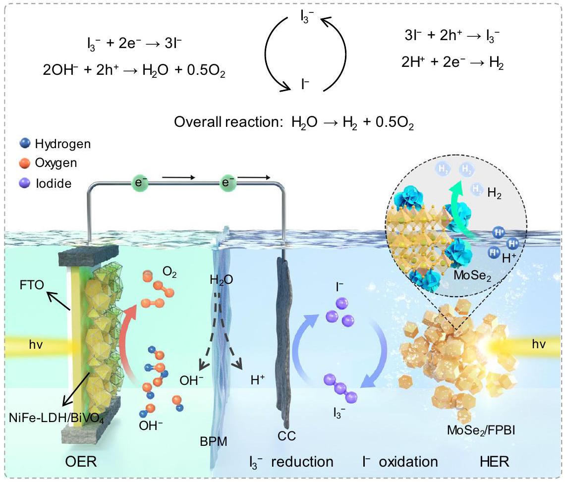
تطور هذه الدراسة نظامًا متكاملًا يعمل بالطاقة الشمسية يتضمن عملية التحفيز الضوئيخلية تفاعل تطور الهيدروجين (HER) مفصولة عنتفاعل تطور الأكسجين (OER) الخلية ووسيط بواسطةشuttle الأكسدة والاختزال (الشكل 1)، الذي يحقق الطاقة الشمسيةالإنتاج من الماء مع STH منالبيروفسكايت الهاليدي المختلط (FPBI، محملة بسيلينيد الموليبدينومتم تطويره كعامل حفاز ضوئي لـالإنتاج أثناء تقسيم HI والأكسدةإلىهيدروكسيد مزدوج طبقي من نيكل وحديد معدل ( يتم استخدام فيلم مزروع على زجاج أكسيد القصدير المخلوط بالفلور (FTO) لعملية الأكسدة المائية (OER)، مع القماش الكربوني المرتبط (CC) لـتقليل. هذا التصميم يسمح بالإنتاج المنفصل لـ و ، مع تجنب رد الفعل العكسي تمامًا (إعادة تركيب و ). بالإضافة إلى ذلك، التفاعلات الجانبية الناتجة عن زوج الأكسدة والاختزال (أكسدة من خلال الثقوب فييمكن قمعها تمامًا لأن خلية OER لا تحتوي على وسطاء الأكسدة والاختزال. بالإضافة إلى ذلك، تم تثبيت البيروفسكايت الجزيئي بنجاح على ركيزة من لوح أكريليك كصفحة محفز ضوئي بمساحة. يتم دمجه بعد ذلك مع NiFe-LDH/BiVO سي سي ( ) التكوين وتم تجميعه في مفاعلات اللوحة المصممة. هذا النظام اللوحي مناسب للتوسع، و تم إنشاء محطة عرض تحتوي على 5 وحدات للتوضيح في الهواء الطلق. ستوكيومترية و يتم إنتاجها وجمعها بشكل منفصل في حاويات مختلفة، مما يحقق كفاءة STH متوسطة قدرهالتحليل الانقسام الكلي للمياه المدفوع بالطاقة الشمسية خلال اختبار استمر أسبوعًا تحت ظروف ضوء الشمس الطبيعي.
النتائج والمناقشة
محفز ضوئي من البيروفسكايت الهاليدي
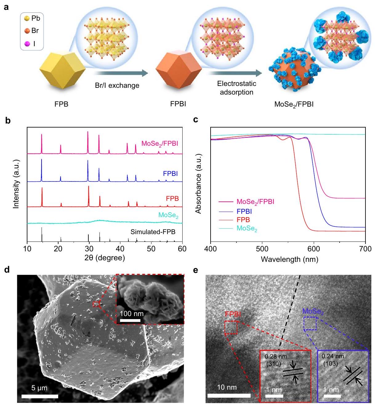
عملية تخليق الـالمركب موضح في الشكل 2أ. على وجه التحديد،تمت أول عملية تخليق لـ (FPB) بواسطة طريقة ترسيب مشترك من محلول مشبع كما أبلغنا سابقًا، وتم الحصول على FPBI لاحقًا من خلال تبادل أيونات الهاليد في الموقع المعزز بالصور في مادة البيروفيسكايت المشبعةحل. بعد ذلك،تم تحميل الزهور النانوية على FPBI كعامل مساعد لتفاعل الهيدروجين.من خلال عملية الامتزاز في محلول الهاليد المائي المشبع بالبيروفسكايت. إمكانيات السطح لـو FPBI هما 78.9 مللي فولت و -26.3 مللي فولت (إمكان الزيتا موضح في الشكل التكميلية 1)، على التوالي، مما يسمح بالترابط الوثيق بينهما. نمط حيود الأشعة السينية (XRD) (الشكل 2b) يؤكد أن FPB له تكوين مكعب مع بلورة جيدة.. عند عملية تبادل أيونات الهاليد، تتحرك قمم الانكسار للعينة قليلاً نحو زاوية أقل، وهو ما ينتج عن الاستبدال الجزئي لأنيونات اليود الأكبر بحجمها بأنيونات البروم الأصغر. بالإضافة إلى الحفاظ على الهيكل المكعب، لا توجد قمم مميزة تتوافق معتظهر، مما يعني تشكيل محلول صلب من البيروفسكايت المختلط الهاليد FPBI بدلاً من FAPbBr 3 المنفصلالمراحل. بسبب ضعف البلورية وانخفاض كمية التحميل منلا توجد قمم مميزة في حيود الأشعة السينية (XRD) لـالمقدمة في نمط حيود الأشعة السينية (XRD).
كل من FPB و FPBI يظهران شكلًا يشبه الدوديكاهدرا بحجمكما هو موضح في صور المجهر الإلكتروني الماسح (SEM) (الشكل التوضيحي 2 أ، ب)، وموحد MoSe الذي تم تصنيعهيقدم شكل زهرة نانوية بحجم 200-300 نانومتر (مكمل
الشكل 1 | توضيح تخطيطي لنظام تقسيم الماء بالطاقة الشمسية وفق مخطط Z مع فصل و الإنتاج. التفاعل الصافي هو انقسام الماء لإنتاج و توسطهشuttle الأكسدة والاختزال. HER تمثل تفاعل تطور الهيدروجين. OER تمثل تفاعل تطور الأكسجين. NiFe-LDH/BiVO يمثل هيدروكسيد النيكل والحديد المزدوج الطبقي المعدل. FPBI/MoSe يمثل (FPBI، محملة بسيلينيد الموليبدينوم. تشير CC إلى قماش الكربون و FTO تشير إلى الزجاج المغطى بأكسيد القصدير المدعوم بالفلور.
الشكل 2 | تخليق MoSe /FPBI المركبات. توضيح تخطيطي لعملية التخليق لـ و المركبات. تمثل الأشكال الاثني عشرية جزيئات البيروفسكايت، وتظهر الرسوم التوضيحية الهيكلية المقابلة في الفقاعات. لاحظ أن أيونات FA غير موضحة لتبسيط الأمر.أنماط XRD لـ FPB، FPBI،المركبات المركبة FPBI و FPB المحاكية للمقارنة. طيف، FPB ، FPBI و /FPBI. “a.u.” في (ب، ج) تعني “وحدات عشوائية”. د صور المجهر الإلكتروني الماسح (SEM) لـ FPBI. تُظهر الإضافة صورة SEM لـصور TEM عالية الدقة (HRTEM) لـ. الصور التي تم إدراجها في الإطارات الحمراء والزرقاء تظهر FPBI وعلى التوالي.
الشكل 2ج).توزع النانوزهور بشكل متساوٍ على سطح بلورات FPBI الدقيقة في /FPBI المركب (الشكل 2d والشكل التوضيحي 2d). حواف شبكية مختلفة تمامًا تتوافق مع FPBI (0.28 نانومتر، مستوى (310)) و (0.24 نانومتر، مستوى (103)) تم ملاحظته في صورة المجهر الإلكتروني عالي الدقة (HR-TEM) (الشكل 2e)، مما يكشف المزيد عن تشكيل المركب. تؤكد خريطة العناصر باستخدام مطيافية الأشعة السينية المشتتة للطاقة (EDS) (الشكل التكميلي 3) أن جميع عناصر الرصاص (Pb) والبروم (Br) واليود (I) والموليبدينوم (Mo) والسيلينيوم (Se) تتوزع بشكل متجانس في FPBI. تظهر نتائج محتوى العناصر في FPBI الموضحة في الجدول التكميلي 1 نسبة المولات حوالي 6:1. تشير قياسات مطيافية الكتلة بالتحليل الطيفي المقترن بالحث (ICP-MS) إلى أن نسبة الكتلة لتحميل الموليبدينوم والسيلينيوم على الـعينة FPBI هي و على التوالي (الجدول التكميلي 2).
يقع حد الامتصاص لـ FPB النقي عند حوالي 580 نانومتر، كما هو موضح في طيف الانعكاس المنتشر (DRS) (الشكل 2c). عند عملية تبادل الأيونات، يتم إزاحة حد الامتصاص لـ FPBI إلى حوالي 620 نانومتر، ويحدث ارتفاع كامل لذيل الامتصاص في منطقة الطول الموجي الأطول. ) ربما يكون بسبب أو الأنواع الممتصة على سطح البيروفسكايت. المركب يظهر حافة امتصاص ضوئي متحولة نحو الأحمر وزيادة ملحوظة في ذيل الامتصاص بسبب النجاحالتحميل، الذي يُلاحظ بشكل مشابه في أشباه الموصلات الأخرى المحفزات الضوئية المعدلة بـ. نتائج XPS عالية الدقة لـ Mo 3d و Se 3d في MoSe (الشكل التوضيحي 4a، b) يوضح وجود كل من الطور المعدني 1 T وطور أشباه الموصلات 2 H في العينة المحضرة.زهرة نانويةالتغيرات الإيجابية الملحوظة في العناصرمنمؤشر FPBI المركب مقارنةً بمؤشر FPBI، والتحولات المعاكسة الملحوظة مقارنةً بـ (Mo 3d، Se 3d) تشير إلى تفاعل قوي للإلكترونات بين FPBI و (الشكل التوضيحي 4) . هذا التفاعل يوجه سحابة الإلكترون نحو، وهو مفيد لفصل الشحنات ونقلها في عمليات التحفيز الضوئي اللاحقة.
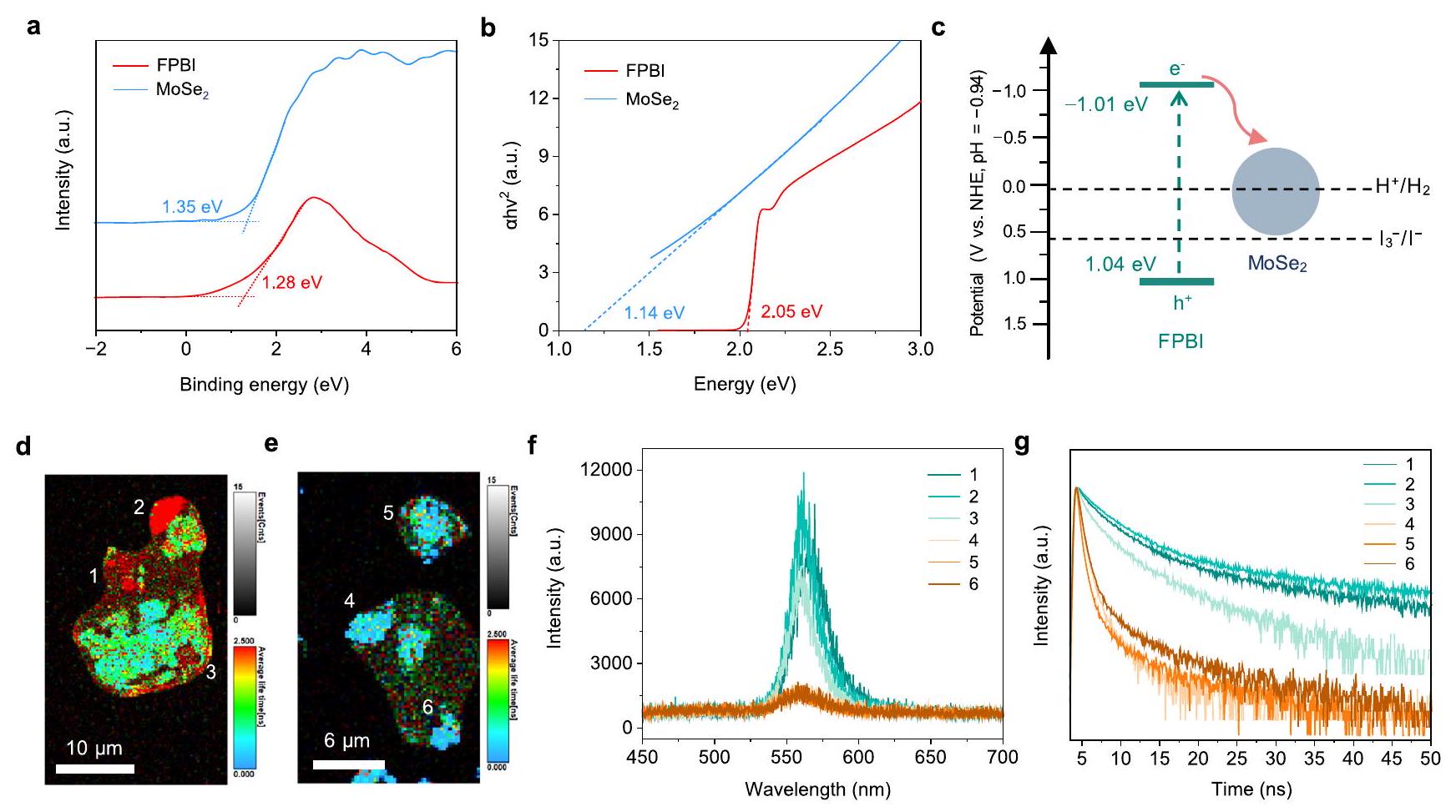
محاذاة النطاقات لـ FPBI و يتم تحديده بواسطة مخطط نطاق التكافؤ XPS (VB-XPS) ومخطط تاوك. الحد الأقصى لنطاق التكافؤ ( ) من FPBI و تم تحديدها لتكون عند 1.04 و 1.11 إلكترون فولت (مقابل NHE)، على التوالي (الشكل 3أ). بالنظر إلى فجوات الطاقة (Eg) لـ FPBI والتي تستنتج من مخططات تاوك (الشكل 3ب) كـ 2.05 و 1.14 إلكترون فولت، على التوالي، (مقابل NHE) من FPBI ويتم حسابها عند -1.01 و -0.03 إلكترون فولت. تعزز هذه المحاذاة نقل الإلكترونات الناتجة عن الضوء في FPBI إلى، يتم الفصل مع وجود الثقوب المحجوبة في FPBI (الشكل 3c). هذا الفصل للشحنات مفيد للاستخدام الفعال للحاملات الناتجة عن الضوء في العمليات الضوئية التحفيزية. يجب ملاحظة أنه، على الرغم من يتميز بوجود فجوة طاقة قدرها 1.14 إلكترون فولت، وهو شديد
الشكل 3 | محاذاة النطاق والتحقيق في ديناميات الحامل. أ مخططات طيف الأشعة السينية للأشعة السطحية (VB-XPS) لـ (FPBI) و الحد الأقصى لفرقة التكافؤ مقابل القطب الهيدروجيني العادييمكن حساب ( ) وفقًا للصيغة:، حيث هو دالة العمل للجهاز (4.20 إلكترون فولت). وبالتالي،من FPBI، ويتم حسابها لتكون 1.04 و 1.11 إلكترون فولت، على التوالي.مخططات تاوك لـ FPBI و. فجوات الطاقة (Eg) لـ FPBI وتم تحديدها عند 2.05 و 1.14 إلكترون فولت، على التوالي. الحد الأدنى لفرقة التوصيل الخاصة بهم ( ) يتم استنتاجه باستخدام المعادلة ، كـ -1.01 و -0.03 إلكترون فولت لـ FPBI و، على التوالي. ج رسم تخطيطي لهياكل النطاقات لـ FPBI والجهود لتفاعلات الأكسدة والاختزال. صور PL لجزيء واحد لـ FPBI (د) و (هـ). طيف الفوتولومينسنس (و) وطيف الفوتولومينسنس المعتمد على الزمن (TRPL) (ز) لـ FPBI و MoSe /FPBI. منحنيات تتوافق مع النقاط المحددة في الجسيمات الموضحة في (د) و(هـ). “و.ح.” في ( ) تعني “وحدات عشوائية”.
الشكل 4 | تقييم أداء التحلل الضوئي لـ HI. أ التحلل الضوئيأنشطة تطور FPB و FPBI و MoSe /FPBI مع تغير MoSe أحجام التحميل من، و تم إجراء التجارب باستخدام 100 ملغ من عينات المسحوق الموزعة فيمحلول مشبع بـ FPBI تحت إشعاع ضوء الشمس المحاكي (1 شمس، AM1.5G،منطقة الإشعاع” ). تشير أشرطة الخطأ إلى الانحراف المعياري (القياسات المستقلة). يتم توفير بيانات المصدر كملف بيانات المصدر. ب تعتمد الكمية الظاهرة على الطول الموجي كفاءة (AQE) منفي التحفيز الضوئيتفاعل التطور. تم حساب قيم AQE باستخدام المعادلة الموضحة في قسم “الطرق”، ونتائج الحساب موضحة في الجدول التكميلي 5. “a.u.” تعني “وحدات عشوائية”. ج. التحفيز الضوئي الدورياختبار الإنتاج باستخدامعينة FPBIمع نشاط ضوئي تمثيلي. تم الحصول على البيانات تحت إشعاع شمس واحد (AMكل دورة تستغرق 3 ساعات. إن النطاق الضيق للطاقة ووجود الطور المعدني 1T يجعله يظهر خصائص شبه موصلة، وبالتالي لا يظهر أي نشاط لتحفيز الهيدروجين الضوئي تحت ظروف الاختبار الحالية (انظر “الطرق”) المستخدمة في هذا العمل. لذلك،يعتبر كعامل مساعد لتفاعل تقليل الهيدروجين (الشكل 3c)، كما هو مذكور في العديد من أنظمة المحفزات الضوئية الأخرى..
آثار المحملةتمت دراسة ديناميات الحاملات في FPBI المرتبطة بالأداء الضوئي التحفيزي باستخدام مجهر متقدم لتألق الجسيمات الفردية (PL). تم تحديد ثلاث نقاط اختبار لكل FPBI وتم اختيار عينة /FPBI على مقياس الجسيمات الفردية لت quantifying شدة PL والانحلال (الشكل 3d، e). المظهر الضعيف لـ PL في صور PL للجسيمات الفردية
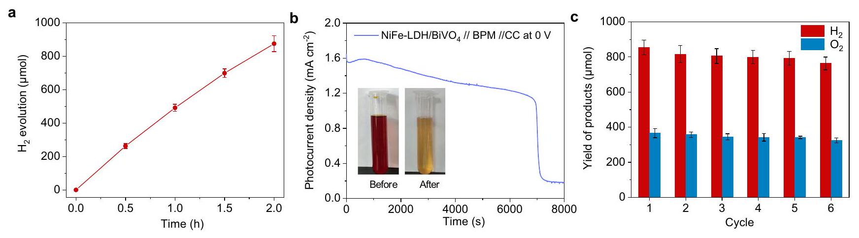
الشكل 5 | تقييم أداء التحلل الضوئي الشامل للماء. أ التحلل الضوئيتطورتم تقييم التجربة باستخدام 100 ملغ منموزعة فيحل مشبع بـ FPBI (بدون ) تحت إشعاع ضوء الشمس المحاكى (1 شمس، AM1.5G، منطقة الإشعاع ). مراقب الكرونوأمبيرومترية لـغشاء ثنائي القطب // تكوين قماش الكربون عند 0 فولت. NiFe-LDH/ وتم غمر قماش الكربون في محلول بورات البوتاسيوم 0.5 م (KBi) ومحلول حمضي غني (المحلول بعد ساعتين من التحفيز الضوئي التطور)، على التوالي. المناطق المغمورة من وكان كل من قماش الكربون تم إجراء الاختبار تحت ضغط 101 كيلو باسكال ومحاكاة إشعاع شمس واحد. ). تُظهر الصور المضافة محاليل البيروفسكايت الحمضية قبل وبعد تفاعل الاختزال. ج اختبار التحليل الضوئي الدوري لتفكيك الماء باستخدام و NiFe-LDH/BiVO كعامل حفاز لتطور الهيدروجين وتطور الأكسجين، على التوالي. التطور و كما هو موضح في و ، كانت ناتجة عن دورة واحدة من تحليل الماء. بعد مرحلة الاختزال في (ب)، تم نقل المحلول الحمضي لبدء جولة جديدة من تطور الهيدروجين الضوئي التحفيزي. تشير أشرطة الخطأ إلى الانحراف المعياري. (تجارب مستقلة). يتم توفير بيانات المصدر كملف بيانات المصدر. (الشكل 3د، هـ)، انخفاض شدة PL منإلىأ.و. (الشكل 3f)، وأوقات حياة PL المختصرة من قيمة متوسطة من 5.1 نانوثانية إلى 1.8 نانوثانية (الشكل 3g والجدول التكميلي 3) منالجسيم بالنسبة إلى FPBI العاري، يعني ت quenching PL والقيود الفعالة على إعادة التركيب الإشعاعي لحاملات الشحنة عن طريق التحميلعلى FPBI. تظهر نتائج التوصيف الكهروكيميائي لزيادة التيار الضوئي في استجابة التيار الضوئي العابر (الشكل التكميلي 5) ونصف الدائرة الأصغر في طيف الامتياز الكهروكيميائي (EIS، الشكل التكميلي 6) الدور الحيوي لـفي تسهيل فصل الشحنات والقدرة على تحسين الأداء الضوئي المحفز في الهيكل المركب.
التحفيز الضوئيتمت دراسة نشاط تطور الهيدروجين للمواد المحفزة من نوع البيروفسكايت الهاليدي المستحصلة (100 ملغ) في محلول هيدروهاليكي مائي مشبع بمادة FPBI تحت إشعاع ضوء الشمس المحاكي (1 شمس، AM1.5G،منطقة الإشعاع ). كما هو موضح في الشكل 4a، من خلال تحسين كمية التحميل لـ (1.0-2.5 وزن%)، تحفيز ضوئي معززنشاط التطور بمعدليتم الحصول عليه باستخدام المركب FPBI، الذي هو تقريبًا 69 مرة و 15 مرة أعلى من تلك الخاصة بـ FPB و FPBI، على التوالي. الفيلم التوضيحي الإضافي 1 يظهر التحفيز الضوئي تطور أكثر من 100 ملغ من مسحوق المحفز الضوئي الموزع في مفاعل كوارتز على نطاق المختبر (1 شمس، AM1.5G،منطقة الإشعاع، ضغط الخلفية 1 كيلو باسكال). يتم حساب كفاءة STH المقابلة لتفكيك HI كـ (المستمدة من 3 اختبارات مستقلة) بناءً على ظروف القياس المذكورة أعلاه، والتي تتفوق على المحفزات الضوئية من هاليد البيروفسكايت المبلغ عنها سابقًا (الجدول التكميلي 4). الكفاءة الكمية الظاهرة (AQE) لـتحت أطوال موجية مختلفة من إشعاع الضوء في، و940 نانومتر تم قياسها لتكون و 0، على التوالي، كما هو موضح في الشكل 4ب والجدول التكميلي 5. يجب ملاحظة أن الأنشطة الضعيفة لتفاعل تطور الهيدروجين تظهر في الأطوال الموجية الأطول ( نتيجة للمرحلة الغنية باليود التي تتكون من خلال فصل الطور الناتج عن الإشعاع الضوئي. يتم تأكيد ذلك من خلال طيف DRS وأنشطة HER الضوئية لـ FPBI العاري تحت إشعاع الضوء عند أطوال موجية من (الشكل التوضيحي 7). تتماشى قيم AQE مع طيف امتصاص الضوء للمواد المحفزة الضوئية، مما يشير إلى أن التفاعلات الضوئية تمت عبر انتقالات فجوة الطاقة. تظهر قياسات الاستقرار على المدى الطويل (الشكل 4c) عدم وجود تدهور واضح في الـنشاط التطور بعد 20 دورة اختبار (3 ساعات لكل دورة)، مما يُظهر استقرار ملحوظ لـمحفز FPBI. تظهر تحليلات XRD و SEM و XPS (الأشكال التكميلية 8-10) عدم وجود تدهور أو تدهور ملحوظ في الهيكل والشكل. /FPBI بعد 20 دورة اختبار من التحفيز الضوئي. بالإضافة إلى ذلك، تؤكد نتائج ICP-MS (الجدول التكميلي 2) أنه لا توجد تغييرات كبيرة في نسب الكتلة لمعدني الموليبدينوم والسيلينيوم في الـالمركب بعد التفاعل، مما يشير إلى أنيبقى مستقراً إلى حد كبير طوال عملية التفاعل.
لأخضر قابل للتوسع وعملي الإنتاج، يُعتبر الماء مصدرًا أكثر مثالية نظرًا لوفرتة وفعاليته من حيث التكلفة. علاوة على ذلك، فإن إعادة التركيب لـمعيمكن أن يمكّن من تجديد المياه من خلال الاحتراق أو في خلايا الوقود، وبالتالي إغلاق الدورة بطريقة خالية من الكربون. لتحقيق انقسام المياه بشكل كامل دون الحاجة إلى مواد تفاعلية تضحية، فإنالذي تم توليده من أكسدة HI بواسطة الثقوب الناتجة عن الضوء فييجب أن تخضع للتقليص مرة أخرى إلىبينما تتطور في الوقت نفسه. لتحقيق هذه الغاية، نستفيد من تكوين Z-scheme ونصمم نظامًا مفصولًا و نظام التطور، حيث يتم فصل غرفة HER عن جانب أكسدة الماء بواسطة غشاء ثنائي القطب. عينة المسحوق من بيروفسكايت الهاليد FPBI محملة بـيتم تطبيقه من أجل التحفيز الضوئي الفعالالإنتاج عن طريق تقسيم HI في خلية HER. تم تعديل NiFe-LDHفيلم مزروع على زجاج FTO في غرفة مختلفة يُستخدم لأكسدة الماء لإنتاج، و الـ الفيلم مرتبط بقماش كربوني تجاري مغمور في محلول حمضي في خلية HER، يقبل الإلكترونات الناتجة عن الضوء منلتقليل المحتوى، وهو الناتج الثانوي لعملية HER (الشكل 1). الغشاء ثنائي القطب المستخدم لفصل غرف HER و OER يتكون من طبقة تبادل كاتيون وطبقة تبادل أنيون، مما يسمح بــوتفكك من الماء عند واجهة طبقات التبادل للهجرة إلى جانبي تفاعل الهيدروجين (HER) وتفاعل الأكسجين (OER) على التوالي.. من خلال هذه الطريقة، يتم ربط عملية التحليل الضوئي للهيدروجين عبر انقسام اليود مع عملية أكسدة الماء من خلال الأكسدة.شuttle الأكسدة والاختزال، مكونًا نظام تقسيم الماء بشكل Z.
نحن نتحقق من جدوى التصميم المذكور أعلاه من خلال طريقة تفاعل من خطوتين: يتم إجراء تفاعل التحفيز الضوئي لإنتاج الهيدروجين أولاً في محلول حمض الهيدروهاليد دونيستخدمكعامل محفز ضوئي؛ بعد ذلك،يتم استخدام المحلول الغني بعد عملية HER كحل يحتوي على مستقبلات الإلكترونات للتفاعل مع OER باستخدام NiFe-LDH/BiVO4//CC لأكسدة الماء و
الشكل 6 | نظام الألواح لتفكيك الماء على نطاق واسع في الهواء الطلق. أ رسم تخطيطي لوحدة متسلسلة لتفكيك الماء.عرض مكبر لوحدة تكسير الماء المزدوجة التي تشمل خلية HER وخلية OER. الورقة الحمراء العلوية هي MoSe / فيلم ( )، والورقة الصفراء السفلية هي NiFe-LDH/BiVO فيلمصورة لنموذج تجريبي كبير في الهواء الطلق لنظام تقسيم المياه الكلي المدفوع بالطاقة الشمسية (5 وحدات). التخطيط الهيكلي لمفاعل HER الفرعي (د) ومفاعل OER الفرعي (هـ).عائد المنتجات وSTH المقابل لنظام وحدة واحدة. كل دورة هي. تم جمع هذه البيانات في المختبر الوطني الرئيسي لمواد البلورات، جامعة شاندونغ، الواقع في جينان، الصين. امتدت فترة جمع البيانات من 27 أكتوبر إلى 2 نوفمبر 2023. تت correspond أشرطة الخطأ لكفاءة STH إلى الانحراف المعياري، استنادًا إلى 7 عينات تم أخذها في أوقات مختلفة بين الساعة 11:00 و 14:00 في نفس اليوم. تم توفير بيانات المصدر كملف بيانات مصدر.تم تسجيل مخططات معدل التطور، STH، واعتماد شدة الضوء في اليوم الذي شهد أعلى مستوى لـ STH، 29 أكتوبر 2023. خفض في حجرتين متجاورتين متصلتين بغشاء ثنائي القطب (الشكل التكميلي 11). يجب أن نلاحظ أنه في أنظمة تقسيم HI الضوئية المبلغ عنها في الوقت الحاضرإضافةلا غنى عنه من أجل تقليل انتقائيإلى، لأن المنتج يمكن أن تتداخل مع امتصاص الضوء للمواد المحفزة الضوئية، وقد ثبت أن الثقوب الناتجة عن الضوء بواسطة البيروفسكايت تستهلك فقط بواسطةبدون مباشرةأكسدة“. في هذا العمل، نقوم بحل هذه المشكلة الصعبة التي طال أمدها ونزيلمن التحفيز الضوئيحل التطور من خلال بناء نظام تدفق متكامل. كما هو موضح في الشكل 5أ،منيتطور خلال الـ 30 دقيقة الأولى علىتحت إضاءة الشمس المحاكية (1 شمس،حتى في غياب، مما يتوافق مع STH من (تم الحصول عليها من 3 قياسات مستقلة). ومع ذلك، فإن معدل تطور الهيدروجين الضوئي التحفيزي ينخفض قليلاً مع تقدم التفاعل بسبب زيادة تركيز المؤكسد.، الذي يتداخل مع امتصاص الضوء من المحفز الضوئي. الناتجيتم بعد ذلك استخدام محلول الحمض الغني للتفاعل مع عملية الأكسدة الضوئية، خلال ذلكيتم تقليله واستعادته إلى.
لتسهيل الموارد التعليمية المفتوحة، BiVOيتم أولاً زراعة الفيلم على ركيزة زجاجية FTO، ثم يتم تحميل NiFe-LDH عليهاالفيلم كعامل مساعد لـتطور لتحسين فصل الشحنات وتوفير مواقع نشطة لتحويل الماء إلىتحويلأنماط حيود الأشعة السينية و NiFe-LDH/BiVO (الشكل التوضيحي 12) يوضح هيكل الـلا يوجد تغيير واضح بعد التحميل بـ NiFe-LDH. NiFeLDH يلف بشكل متساوٍ الشكل الدودي.كما هو موضح في صور SEM (الشكل التكميلي 13). علاوة على ذلك، فإن عناصر البزموت والفاناديوم والأكسجين والنيكل والحديد موزعة بشكل متساوٍ كما تم الحصول عليه من خريطة SEM (الشكل التكميلي 14). تكشف نتائج EDS لمحتويات العناصر، كما هو موضح في الجدول التكميلي 6، أن نسب الكتلة للنيكل والحديد فيتُقدَّر بـ و ، على التوالي. في كتلة OER، الإلكترونات المتولدة من الضوء فينقل إلى القماش الكربوني المرتبط، الموجود في الغرفة المجاورة المملوءة بمحلول الحمض لـتقليل، مما يترك الثقوب الناتجة عن الضوء تهاجر إلى مواقع NiFe-LDH لـالتطور. يمكن أن يصمم مثل هذا التصميم لقمع رد الفعل الخلفي تمامًا (إعادة تركيب المتطورين و من الماء) وتفاعل جانبي (أكسدةعلى ). يتم مراقبة أداء التحفيز الضوئي لتقليل اليود بواسطة محطة عمل كهربائية ولكن دون إضافة انحياز خارجي (الشكل التكميلي 15). بعد تفاعل ضوئي لمدة 1.9 ساعة، 88.6 منالذي تم إنتاجه خلال ساعتين من تفاعل الهيدروجين على MoSeتم تقليل FPBI (الشكل التوضيحي التكميلي 16). التيار الضوئي بين النيكل والحديدوقماش الكربون ينخفض إلى قيمة دنيا تبلغ حوالي. (الشكل 5ب)، وأخيرًا يتحول المحلول البني الداكن إلى أصفر باهت، كما هو موضح في الصور المرفقة في الشكل 5ب. الغاز المنبعث خلال هذه التجربة هو. نتيجة لذلك، من خلال التفاعل الكامل الذي يتضمن حيزين لـ HER و OER مرتبطين بـشuttle الأكسدة والاختزال، ستوكيومترية و يتم إنتاجها وجمعها بشكل منفصل من خلال التحليل الكهربائي للماء المدفوع بالطاقة الشمسية. يتم حساب STH على أنه (المستمدة من 3 قياسات مستقلة)، والتي تعتبر من أعلى النطاقات في أنظمة التحلل الضوئي الكلي للمياه المبلغ عنها (الجدول التكميلي 7) . سبب الانخفاض التدريجي الطفيف لـالإنتاج مع استمرار دورات الاختبار (الشكل 5c) هو أن تجربة تقسيم الماء هذه تتم بطريقة من خطوتين، في كل دورة بعد ساعتين من تفاعل التحفيز الضوئي لإنتاج الهيدروجين، يتم إعادة تدوير مسحوق المحفز الضوئي منمحلول حمضي غني بواسطة الطرد المركزي، ثم أعيد استخدامه. خلال هذه العمليات، هناك خسائر لا مفر منها من المحفز الضوئي. بالإضافة إلى ذلك، خلال عملية OER وعملية التخفيض، فقط حواليمنيتم تقليله. وهذا يؤدي إلى نسبة أعلى قليلاً منأكثر من 2. لتحسين الـمن خلال توليد HER، نمدد مدة تجربة تقليل اليود. كما هو موضح في الشكل التوضيحي 17، فإن زيادة وقت الفوتوخفض من ساعتين إلى أربع ساعات تعزز من تقليلمنإلى. ومع ذلك، على الرغم من هذه الزيادة، فإن STH لهذه التجربة ينخفض من إلىبسبب التعرض المطول لإشعاع الضوء. وبالتالي، من الضروري تحسين أوقات التفاعل بشكل عقلاني لكل من وموارد التعليم المفتوح لتعظيم STH. علاوة على ذلك، يتم تحديد AQE لموارد التعليم المفتوح لـ NiFe-LDH/BiVO4 كـ عند 420 نانومتر (الشكل التوضيحي 18)، وهو أقل بكثير من ذلك الخاص بتفاعل تقليل الهيدروجين ( عند 420 نانومتر، الشكل 4ب). يمكن تحسين كفاءة النظام الضوئي الحفاز الحالي بشكل أكبر من خلال استخدام محفز ضوئي لتفاعل الأكسدة الأكثر كفاءة من NiFe-LDH/BiVO4.
نظام الألواح لتفكيك المياه في الهواء الطلق على نطاق واسع
أظهرت الأنظمة الضوئية الحفازة في شكل لوحات إمكانيات كبيرة للتطبيق العملي على نطاق واسعالإنتاج من خلال تحليل الماءفي عملنا الحالي، نستكشف توسيع نظام Z-scheme المذكور أعلاه لتفكيك الماء المدفوع بالطاقة الشمسية، من خلال تطوير مفاعلات لوحية بمكونات معيارية سهلة التوسع.تم إعداده في شكل فيلم، مما يجعله قابلاً للإدماج في مفاعل لوحي، النقطة الرئيسية هي تطوير أوراق البيروفسكايت. لهذا الغرض، يتم تثبيت البيروفسكايت الهاليدي على لوحة بلاستيكية أكريليكية بواسطة طريقة بسيطة لمعالجة المحلول باستخدام رباعي إيثيل أورثوسيليكات كعامل ربط (الشكل التكميلي 19). تُظهر خصائص الميكروستركتشر (الشكل التكميلي 20) أن ورقة المحفز الضوئي تحتوي على جزيئات بيروفسكايت بحجم عدة ميكرومترات، مع تشكيل جزيئات الربط رباعي إيثيل أورثوسيليكات/سيليكا هياكل مسامية متاحة لنقل الكتلة. مثل هذه الورقة المحفزة الضوئية من البيروفسكايت ) ينتج عن طريق HI الانقسام مع STH منفي محلول هيدروهالي يحتوي علىتحت ضوء الشمس المحاكى الإضاءة (1 شمس، AM1.5G،، الشكل التوضيحي التكميلي 21). علاوة على ذلك، يظهر نشاط التحفيز الضوئي لتفاعل تقليل الهيدروجين زيادة مع كمية تحميل البيروفسكايت من 10 إلى 70 ملغ علىلوحة قاعدة من الأكريليك، مع نشاطComparable لنظام تعليق المسحوق الذي يحتوي على نفس كمية المحفز الضوئي (الشكل التكميلي 22). ومع ذلك، بعد 70 ملغ، لم يعد نشاط HER لأوراق البيروفسكايت يظهر زيادة ملحوظة مع إضافة المزيد من المحفز الضوئي، حيث يصل إلى مستوى مستقر. ومن المحتمل أن يكون ذلك بسبب أن تعرض المواقع النشطة يميل إلى التشبع على ركيزة معينة ذات مساحة محدودة (مع الحد الأقصى للكمية الفعالة من المحفز الضوئي حوالي. ). على النقيض من ذلك، يمكن أن يمكّن نظام التعليق الذي يحتوي على محلول سائل أكثر تحت التحريك من وجود المزيد من المحفزات الضوئية، ولهذا السبب يتم الحصول على نشاط ضوئي محفز أعلى في نظام التعليق الذي يحتوي على كميات أكبر من المحفزات الضوئية ( ومع ذلك، فإن أوراق المحفز الضوئي تقلل بشكل كبير من كمية محلول المتفاعل المطلوب وتلغي الحاجة إلى نظام تحريك إضافي، وهو أمر لا غنى عنه في أنظمة التعليق. هذه المزايا مفيدة لتطوير وتعزيز التطبيقات الموسعة لأنظمة التحفيز الضوئي.
المفاعل المصمم للاختبارات على نطاق واسع يتكون من خلايا HER و OER متتالية (تحت المفاعلات)، والتي تتصل وتدور بواسطة مضخة بيرستالتية، مما يسمح بمنتج الأكسدة منفي خلية HER الحمضية للتدفق إلى خلية OER، بالإضافة إلى تدفق I- المخفض مرة أخرى إلى خلية HER، كما هو موضح بشكل تخطيطي في الشكل 6a. أما بالنسبة للفرع الفرعي HER، فإن الحجرة تتكون منلوحة القاع وغطاء زجاجي من الأكريليك بنفس الحجم، مع عمق طبقة محلول الحمض (أي ارتفاع المساحة للريكتور) يبلغ 3 مم (الشكل 6d). يمكن توسيع ورقة البيروفسكايت بسهولة إلى منطقة أكبر من خلال طريقة صب المحلول. على سبيل المثال،تم تحضير فيلم المحفز الضوئي بشكل متاح على اللوحة السفلية من الزجاج الأكريليكي لمفاعل اللوحة (الشكل التكميلي 23). ثم تم تقييم أداء مفاعل HER المدمج مع ورقة البيروفسكايت في ظروف خارجية (من 13:00 إلى 15:00، جامعة شاندونغ، تحت ضوء الشمس، و تطورت في ساعتين في المحلول الحمضي دون عند الضغط الجوي (الشكل التوضيحي 24). من ناحية أخرى، الفيلم مرتبط بـقماش الكربون لتجميع خلية OER مغطاة بنافذة من الأكريليك (الشكل 6e). يتم تقسيم هذا الحجرة OER إلى حجرتين بواسطة غشاء ثنائي القطب من أجلتقليل والتطور الذي حققته الأقمشة الكربونية و، على التوالي.
تم إجراء اختبار خارجي لمدة 7 أيام (من 11:00 إلى 14:00 كل يوم) في المختبر الوطني الرئيسي لمواد البلورات، جامعة شاندونغ. ) تحت إضاءة الضوء الطبيعي. خمس وحدات نموذجية ( FPBI، الشكل 6ب يُظهر العرض المُكبر لوحدة واحدة) تم دمجها لتوضيح عملية التوسع (من حيث المبدأ، يمكن دمج عدد مُرغوب فيه من الوحدات، بشرط أن تكون المضخة الدوارة قادرة على توفير القوة الدافعة الكافية لـإنتاج الغاز من النظام هو و لـ HER و OER، على التوالي (الشكل التوضيحي 26)، مما يدل على تفاعل صافي لعملية تحليل الماء بشكل كامل دون إضافة مادة تضحوية. يحقق نظام اللوحة متوسط STH قدره (الشكل 6f، الشكل التوضيحي 27). أعلى قيمة STH لـتم الحصول عليه فيأكتوبر 2023، الساعة 11:30 صباحًا عندما كانت شدة ضوء الشمس (الشكل 6g والفيلم التكميلي 2). هذه القيمة هي نصف تلك الموجودة في نظام تعليق المسحوق لأن الحد الأقصى لتحميل المحفز الضوئي الفعال على ركيزة اللوحة ( ) تحد من نشاطها الضوئي الحفاز (الشكل التكميلي 22). علاوة على ذلك، فإن تجانس وجودة فيلم البيروفسكايت ذو المساحة الأكبر ( ربما ليس جيدًا كما هو في ورقة أصغركما هو موضح في الشكل التوضيحي 23. مشكلة أخرى مرتبطة في هذا النظام الموسع هي أنه، عند حدوث التفاعل الضوئي التحفيزي، فإن فيلم البيروفسكايت يتقشر إلى حد ما من الركيزة (الشكل التوضيحي 28)، مما يتسبب في تدهور هيكل اللوحة. لتعزيز الأداء، فإن التعديلات ضرورية في اختيار عامل الربط المناسب، والركيزة، وطريقة الطلاء. ستزيد هذه التعديلات من كمية التحميل الفعالة للبيروفسكايت على الركيزة وتضمن اتصالًا أكثر حميمية، مما يعزز النشاط والاستقرار. بالإضافة إلى ذلك، هناك حاجة إلى عمل مفصل لتحسين الأنظمة المستقبلية. على سبيل المثال، تركيزوسيط الأكسدة والاختزال، الذي يعد عاملاً يؤثر على كفاءة نظام STH الخارجي، يحتاج إلى إدارة دقيقة. يمكن التحكم في هذه التركيزات عن طريق ضبط تدفق السائل في مضخة بيرستالتية.
بغض النظر عن التصميم المختار لأجهزة الوقود الشمسي، يجب مراعاة عدة قيود رئيسية للتطبيقات العملية، بما في ذلك المتطلبات الأساسية للكفاءة، والاستقرار، والتكلفة، وقابلية التوسع. على الرغم من أن كفاءة STH لجهازنا حالياً أقل من تلك الخاصة بالتحليل الكهربائي المدفوع بالطاقة الشمسية لتفكيك الماء بشكل عام على نطاق المختبر، إلا أن جهازنا يظهر مزايا في البساطة، والجدوى الاقتصادية، وقابلية التوسع (الجدول التكميلي 8). والأهم من ذلك، أن التصميم الفريد لنظام Z-scheme الضوئي الخاص بنا لا ينتج فقط و في خلايا منفصلة ولكنها أيضًا تقمع بشكل فعال التفاعلات الجانبية والخلفية، مما يؤدي إلى تحسين ملحوظ في STH لأنظمة Z -scheme. تقدم هذه الطريقة رؤى قيمة لمعالجة التحديات الحالية في أنظمة Z-scheme وستسرع من التقدم نحو كفاءات أعلى.
باختصار، يُظهر هذا العمل نظامًا متكاملًا وفعالًا لتفكيك الماء مدفوعًا بالطاقة الشمسية بتصميم Z، يتضمن خليتين لتفاعل الهيدروجين (HER) وتفاعل الأكسجين (OER) على التوالي، متصلتين بواسطةوسيط الأكسدة والاختزال. يحقق هذا التصميم فصل و التطور من الماء، مع قمع التفاعلات العكسية والتفاعلات الجانبية التي تحدث عادة في أنظمة التحفيز الضوئي التقليدية من نوع Z، وتجنب عمليات تخزين الغاز المعقدة وعمليات الفصل اللاحقة المرتبطة بمشاكل السلامة. لذلك، فإن الحاليةأرشيف STH منتحت محاكاة شمس واحدة (AM1.5G،بالإضافة إلى ذلك، فإن النظام المصمم ووحدات مفاعل اللوحة متاحة بسهولة للتوسع المتزامن. تُظهر هذه الدراسة أن التصميم الفريد لنظام التفاعل يفتح فرصًا قيمة لتعزيز كفاءة أنظمة تحليل الماء الكلي المدفوعة بالطاقة الشمسية.
طرق
تحضير بروميد الفوراميدينيوم (FABr)
تم تخليق FABr من خلال تفاعل استبدال مزدوج كما أبلغنا سابقًا.. بالتحديد، 5 جرام من أسيتات الفوراميدين (علاء الدين. ) تم إضافته ببطء إلى 7.5 مل من حمض الهيدروبروميك (HBr، ألالدين، في الماء) مع التحريك لتكوين محلول صافٍ وتسخينه عندحتى تم إزالة المذيب تمامًا. تم غسل المسحوق الأبيض الناتج بـ 15 مل من الإيثر (شركة سينوفارم للمواد الكيميائية، المحدودة، AR، ) وجفف في درجة حرارة الغرفة للحصول على FABr .
تحضير المحفزات الضوئية من البيروفسكايت والمحالييل للتفاعلات الضوئية
التم تحضير المساحيق بواسطة طريقة الترسيب المشترك من محلول مشبع. عادةً، 10 جرام من بروميد الرصاص (تم إذابة 99% من مادة علاء الدين في 50 مل من المحاليل المختلطة من حمض الهيدروبروميك وحمض الفوسفور.شركة شانغهاي ماكلين للكيماويات الحيوية المحدودة، AR،في الماء) )، ثم تم إضافة 3.41 جرام من FABr ببطء إلى المحلول مع التحريك بقوة تحت . تم فصل المحلول والمساحيق بواسطة الطرد المركزي، مما أدى إلى الحصول على مساحيق FPB ومحلول حمضي مشبع بـ FPB. ثم تم خلط المحلول الحمضي الناتج مع 3 مل من حمض الهيدريوديك (HI، Aladdin، 55-58%)، تلاه إضافة 0.5 جرام من مساحيق FPB مع التحريك القوي. تم تعريض الخليط لإشعاع ضوء الشمس المحاكي لمدة ساعتين لتسريع تفاعل تبادل الهالوجين والحصول على بيروفسكايت مختلط الهاليد.عينة المسحوق تم فصل FPBI عن محلوله بواسطة الطرد المركزي وتجفيفه فيفي فرن. تم الاحتفاظ بمحلول الحمض الناتج المشبع بـ FPBI كمحلول تفاعل في الاختبارات الضوئية اللاحقة. في التجارب المصممة للتحقيق في النشاط الضوئي المحفز لمادة البيروفسكايت في المحاليل بدونتم تحضير محلول الحمض المشبع بالبيروفسكايت المقابل باتباع إجراءات مشابهة لتلك الموصوفة سابقًا، مع استثناء أنلم يتم إضافته إلى محلول الحمض.
تحضيرزهور نانوية
تم تخليق النانو زهور من خلال عملية حل حراري.. أولاً، 0.484 جرام من ثنائي هيدرات موليبدات الصوديومعلاء الدين.بوروهيدريد الصوديومتم إضافة 0.316 جرام من مسحوق السيلينيوم (Se، ألالدين، 99.9%) إلى دورق يحتوي على 40 مل من محلول الإيثانول، وتم تسخين المحلول إلىبعد التحريك الشديد لمدة ساعتين، تم نقل المحلول إلى وعاء أوتوكلاف مبطن بتفلون سعة 100 مل وتم الاحتفاظ به عندلمدة 24 ساعة. بعد التبريد إلى درجة حرارة الغرفة، تم تجفيف المساحيق السوداء التي تم الحصول عليها من خلال الترشيح بالشفط في فرن مفرغ من الهواء عندللحصول على المنتج النهائي.
تحضير
تم تحضير /FPBI بواسطة طريقة التجميع الذاتي الكهروستاتيكي. على وجه التحديد، مسحوق FPBI الذي تم تصنيعه حديثًا و زهور نانوية ) تم إضافتها إلى دورق سعة 50 مل يحتوي على 30 مل من محلول FPBI المشبع. بعد التحريك لمدة تم الحصول على راسب FPBI من خلال الامتزاز الكهروستاتيكي لـعلى أسطح FPBI.
تحضير فيلم المحفز الضوئي
التم تحضير فيلم المحفز الضوئي على لوحة القاعدة من الأكريليك باستخدام طريقة صب القطرات المعالجة بالحلول بسهولة، باستخدام رباعي إيثيل أورثوسيليكات (شركة إيكوباور للمواد الجديدة، كروسيل-سي 28) كعامل ربط. أولاً، التم تنظيف الزجاج الأكريليكي باستخدام الإيثانول وماء DI. ثم تم إذابة 70 ملغ من FPBI المحضر في 1 مل من N,N-Dيميثيل فورماميد (DMF، شركة شانغهاي ماكلين للكيماويات الحيوية، AR، ). بعد ذلك، وتم إضافة 10 ميكرولتر من رابط رباعي إيثيل أورثوسيليكات وتم تفريقه بواسطة الموجات فوق الصوتية لمدة 10 دقائق. تم إسقاط المحلول على اللوح السفلي من الأكريليك بشكل متساوٍ، ثم تم نقل اللوح إلى فرن عندلمدة 24 ساعة.
تحضيرفيلم
التم تصنيع الفيلم باستخدام طريقة تم الإبلاغ عنها في الأدبيات السابقة“. في البداية، 6.640 جرام من يوديد البوتاسيوم (KI، شركة فوجي فيلم واكو للمواد الكيميائية النقية، ) و 1.940 جرام من نترات البزموت خماسية الماء شركة فوجي فيلم واكو للمواد الكيميائية النقية ) تم إذابتها في 100 مل من الماء المنزوع الأيونات. لضبط حمض النيتريك (شركة كانتو كيميكل، إنك. ) تم إضافته وتم تحريك الخليط لمدة 40 دقيقة. بالتوازي، تم تحريك 40 مل من الإيثانول الذي يحتوي على 0.994 جرام من p-benzoquinone (شركة كانتو كيميكل، 98%) لمدة 30 دقيقة. ثم أضيفت محلول الإيثانول إلى محلول الماء وتم تحريكه لمدة 30 دقيقة إضافية، مما شكل محلول مختلط. تم تخليق فيلم BiOI من خلال الترسيب الكهربائي في إعداد قياسي ثلاثي الأقطاب باستخدام محطة العمل الكهروكيميائية CHI 660E. تم استخدام ركيزة زجاجية FTO نظيفة (FTO، ، مع منطقة مغمورة من ) تم استخدامه كالكاثود العامل. محلول مشبع عملت القطب الكهربائي كقطب مرجعي، بينما تم استخدام ورقة من البلاتين كقطب مضاد. تم إجراء ترسيب أنودي عند جهد ثابت قدره -0.1 فولت لمدة 10 دقائق لإنتاج BiOI. بعد ذلك، تم إضافة 0.45 مل من محلول ثنائي ميثيل سلفوكسيد (DMSO، KANTO CHEMICAL CO., INC.، 99%) يحتوي على 0.2 م من أسيتيل أسيتونات الفاناديوم.، سيغما-ألدريتش، 98%) تم تطبيقه على رقائق BiOI النانوية. ثم تم وضعها في فرن مفلط وحرقتها عند لمدة ساعتين. أخيرًا، الـتم الحصول على الفيلم عن طريق غمر المنتج المستحصل عليه في 1 م هيدروكسيد الصوديوم (NaOH، سيغما-ألدريتش، ) لمدة 30 دقيقة .
تحضير NiFe-LDH/فيلم
تم تعديل NiFe-LDH علىفيلم وفقًا لطريقة هيدروحرارية تم الإبلاغ عنها سابقًا مع بعض التعديلات10 ملغ من نترات الحديد غير المائيةعلاء الدين، المملكة العربية السعوديةو 45 ملغ من نترات النيكل سداسية الماءشركة سينوفارم للمواد الكيميائية المحدودة، AR، ) عادة ما يتم إذابتها في 24 مل من الماء المقطر و 6 مل من DMF (شركة شانغهاي ماكلين للكيماويات الحيوية، AR، ). بعد ذلك، الـتم غمر الفيلم في هذا المحلول مع التحريك لمدة 30 دقيقة. تم وضع العينة المحضرة في أوعية أوتوكلاف مبطنة بتفلون للتفاعل الحلولي الحراري. لمدة 6 ساعات.تم الحصول على الفيلم بعد التنظيف بالماء المنزوع الأيونات والإيثانول.
توصيف
تم تحليل الهياكل البلورية بواسطة حيود الأشعة السينية (XRD) باستخدام جهاز Rigaku MiniFlex 600. تم فحص أشكال السطح عبر المجهر الإلكتروني الماسح (SEM) (Hitachi S-4800)، بينما تم دراسة الهياكل النانوية بالتفصيل باستخدام المجهر الإلكتروني الناقل (TEM) والمجهر الإلكتروني الناقل عالي الدقة (HR-TEM) (JEOL JEM2100F). تم تسجيل أطياف التحليل الطيفي للأشعة السينية (XPS) على جهاز طيفي Thermo Scientific ESCALAB Xi+. تم التحقيق في خصائص الامتصاص البصري باستخدام طيف الانعكاس المنتشر للأشعة فوق البنفسجية-المرئية (UV-vis DRS) مع جهاز قياس الطيف Shimadzu UV-2600. تم التقاط صور وأطياف PL لجزيئات مفردة باستخدام نظام مجهر مسح ضوئي متداخل (PicoQuant, MicroTime 200) مقترنًا بمجهري الفلورسنت المقلوب Olympus IX71. تم إجراء التحفيز باستخدام ليزر بقدرة 405 نانومتر مع قدرة تحفيز نموذجية منتم إجراء قياسات الفوتوإلكتروكيميائية في نظام كيميائي كهربائي قياسي مكون من ثلاثة أقطاب باستخدام محطة عمل كهربائية CHI 660E في ثنائي كلور الميثان المحتوي على 0.05 م من هيكسافلورو فوسفات التترا بوتيل أمونيوم (TBAPF).تم إجراء استجابات التيار الضوئي المتقطع وEIS عند 0.5 فولت مقابلباستخدام مصباح زينون بقوة 300 واط مع فلتر AM 1.5G كمصدر للضوء، أيضًا على جهاز العمل الكهربائي CHI 660E.
تحفيز ضوئيقياسات التطور
التحفيز الضوئيتم إجراء تجارب التطور في وسط مائيمحاليل حمضية مشبعة بمادة البيروفكسايت المذابة، داخل وعاء إشعاعي علوي (قطر المفاعل: 2 سم، منطقة الإشعاع: ما لم يُذكر خلاف ذلك)، والذي كان متصلًا بنظام دوران الغاز المغلق بالزجاج. كانت مصباح زينون بقوة 300 واط (CELHXF300) مع فلتر AM 1.5 G هو مصدر الضوء، وتم معايرة شدته إلىباستخدام مقياس القدرة الضوئية (PL-MW2000). تم خلط 100 ملغ من المحفز الضوئي مع 10 مل من محلول حمضي مشبع بمادة البيروفسكايت أثناء التحريك المستمر. لاختبار التحفيز الضوئي لـتم وضع فيلم البيروفسكايت، ورقة المحفز الضوئي المودعة على لوحة بلاستيكية أكريليكية، في قاع مفاعل زجاجي أسطواني (قطر: 7.2 سم) يحتوي على 50 مل من محلول حمضي. المقارنة بين الأصغر ( ) وأكبر ( تم إجراء تفاعلات صفائح البيروفيسكايت في مفاعل لوحي تحت ظروف طبيعية في الهواء الطلق مع إشعاع ضوء الشمس. تم تنفيذ التفاعلات عند ضغط خلفي قدره 1 كيلو باسكال وتم تبريدها باستخدام مياه متداولة عندما لم يُذكر خلاف ذلك.
تم تحليل كميات الغاز المنبعث باستخدام جهاز كروماتوغرافيا الغاز (ShiweipxGC-7806) مع الأرجون كغاز حامل. لتقييم استقرار المحفز الضوئي، تم إجراء اختبار تحفيز ضوئي دوري كل 3 ساعات لمدة 20 دورة، مع إعادة التقييم بعد كل دورة. تم قياس الكفاءة الكمية الممتصة (AQE) باستخدام نفس مصباح زينون بقوة 300 واط مزود بفلتر تمرير نطاق، وتم تحديد تدفق الفوتونات للضوء الساقط باستخدام مقياس الطيف الضوئي PL-MW2000.
تم حساب AQE لتفكيك HI الضوئي باستخدام المعادلة التالية:
كفاءة STH في تقسيم HI الضوئي: الجهد القياسي لتقليل الهيدروجين وإمكانات الأكسدة إلىهي O و 0.53 فولت (مقابل NHE)، على التوالي. باستخدام معادلة نيرنست وتركيز الأيون المطلوب من ( الشكل التوضيحي التكميلي 29)، إمكانيات الخلايا للتفاعلات و تم حسابها لتكون 0.056 فولت و 0.437 فولت مقابل NHE، على التوالي، مما يعطي جهدًا لتفكيك HI قدره 0.381 فولت. تم تقدير كفاءات STH باستخدام المعادلة التالية:
تقييم مختبري على التحلل الضوئي الشامل للمياه تم إجراء التحلل الشامل للمياه على نطاق مختبري بطريقة تفاعلية من خطوتين. أولاً، تم إجراء تفاعل التحلل الضوئي للهيدروجين.محلول حمضي بدونتم إضافته إلى 10 مل منمحلول مشبع بمذاب FPBI لمدة ساعتين من اختزال البروتونتجارب الأكسدة (AM 1.5 G، ). بعد ذلك، الـتم فصل المحلول الغني الناتج عن عملية HER عن المحفز الضوئي من نوع البيروفسكايت بواسطة الطرد المركزي، ونُقل لاستخدامه كمحلول يحتوي على مستقبلات الإلكترون ليتفاعل مع OER في خلية من نوع H متصلة بواسطة غشاء ثنائي القطب (Fumasep).فبم،مع منطقة العمل ). تحديدًا، NiFeفيلمتم استخدامه كعامل حفاز ضوئي OER في محلول بورايت البوتاسيوم بتركيز 0.5 م.مع قماش كربوني موصول بسلك (CC،غارق في-محلول حمضي غني في الغرفة المجاورة الأخرى. ضوء الشمس المحاكى (AM 1.5 G، ) تم استخدامه كمصدر للضوء بواسطة مصباح زينون بقوة 300 واط مزود بفلتر AM1.5. تحت الإضاءة، يتم توليد الإلكترونات الضوئية في تم تحويله إلى مركز الاتصال المرتبط بـالخفض، مما يترك الثقوب الناتجة عن الضوء تهاجر إلى مواقع NiFe-LDH السطحية لـالتطور. بعد تقليصإلىلون المشبع بالبيروفسكايتتحولت المحلول إلى أصفر شفاف ضحل، وتم استخدام هذا المحلول لإجراء جولة جديدة من التحفيز الضوئي.اختبارات الإنتاج. قبل التجربة،تم تمرير الغاز عبر المتفاعلات لمدة نصف ساعة لإزالة المذاب. كانت التفاعلات تعمل عند ضغط خلفي قدره 1 كيلو باسكال وتم تبريدها باستخدام مياه متداولة عند ما لم يُذكر خلاف ذلك. تم تحليل كميات الغاز المنبعث بواسطة جهاز كروماتوغرافيا الغاز (ShiweipxGC-7806) مع الأرجون كغاز حامل.
تم حساب STH لتفكيك الماء الكهروضوئي الكلي من الجهد القياسي للأكسدة والاختزال لـالأكسدة وإمكانات الاختزال، باستخدام المعادلة التالية:
يرجى ملاحظة أن مدخلات الطاقة، سواء كانت يدوية أو متعلقة بالمعدات، مثل الطرد المركزي، لفصل ونقل محلول الحمض بين خلايا HER و OER، تم تجاهلها هنا.
اختبارات ضوئية كيميائيةتقليل وتم إجراء القياسات الضوئية الكهروكيميائية على جهاز العمل الكهروكيميائي CHI 660E وفي نظام تقليدي ذو قطبين مع غشاء ثنائي القطب (BPM، فوماسيب)فبم، مع منطقة عمل تبلغ ) لفصل خلية OER مع -خلية الاختزال. تم اختيار الغشاء الثنائي القطب لأنه سمح بـوتم فصلها عن الماء عند واجهة طبقة التبادل للهجرة إلى الجانبين الحمضي لتفاعل الهيدروجين (HER) والقلوي لتفاعل الأكسجين (OER) على التوالي، مما يجعلها أكثر ملاءمة لتفكيك الماء في النظام الحالي مقارنة بغشاء تبادل البروتون.
مصباح زينون بقوة 300 واط مزود بفلتر AM1.5Gتم استخدامه كمصدر للضوء. كانت الأنود الضوئي هو NiFe-LDH/BiVO، وكان المحلول الكهربائي 0.5 م كيب. كانت القطب في حجرة الفوتوكاثود هي وكان الإلكتروليت مشبعًا بالبيروفسكايتحل (يحتوي على غني، ) بعد التحفيز الضوئي تفاعل الإنتاج. التحليل الضوئي الكهروكيميائي على المدى الطويلتقليل وتم تنفيذ تجربة الإنتاج عند 0 فولت.
وحدات نظام التحفيز الضوئي الكبيرة في الهواء الطلق
تضمن مفاعل اللوحة الخارجية خلايا HER وOER المتتالية (تحت المفاعلات)، والتي كانت متصلة وتدور بواسطة مضخة بيرستالتية. أما بالنسبة لتحت المفاعل HER، فقد كانت الحجرة مكونة منلوحة القاع وغطاء زجاجي بلاستيكي بنفس الحجم، مع عمق طبقة محلول الحمض (أي ارتفاع مساحة التفاعل) يبلغ 3 مم.تم تحضير الفيلم الضوئي المحفز بالطريقة نفسها التي تم بهاعينة. تم طلاء اللوحة السفلية بطبقة فوتوكاتاليتيكية، وتم تثبيت الجزء وغطاء النافذة من الأكريليك بواسطة لاصق قوي. تم تقسيم المفاعل الفرعي OER إلى حجرتين بواسطة غشاء ثنائي القطب يحتوي علىنيفيفيلم و، على التوالي، والتي كانت متصلة بأسلاك لنقل الإلكترونات الناتجة عن الضوء. كانت أحجام NiFe-LDH/BiVO غرفة و غرفة CC كانت و على التوالي، وكان مادة المفاعل هي نفسها كما في المفاعل الفرعي HER. غشاء ثنائي القطبمع منطقة عمل تبلغ ) تم استخدامه لفصل هذين الحجرتين. تم ختم الأكريليك وأجزاء التثبيت باستخدام لاصق قوي، وتم تأمين الحجرتين بواسطة براغي.
تم تجهيز كل غرفة بحلقة مطاطية بينها وبين الغشاء الثنائي القطبية لضمان إحكام غلق المفاعل. يشكل مفاعل فرعي لتفاعل الهيدروجين ومفاعل فرعي لتفاعل الأكسدة المتصلة بواسطة مضخة دائرية وحدة معيارية. تم دمج خمس وحدات معيارية كعرض (من حيث المبدأ، يمكن دمج أي عدد مرغوب من الوحدات إذا كانت المضخة الدائرية توفر القوة الدافعة الكافية لتدوير السوائل). و تم جمع المنتجات الناتجة عن التفاعل بشكل منفصل بواسطة طريقة الصرف. كانت أنابيب دخول/خروج الغاز/السائل مصنوعة من خرطوم مطاطي مقاوم للأحماض (القطر الخارجي 3 مم، القطر الداخلي 2 مم). تم إجراء اختبار خارجي لمدة 7 أيام في المختبر الوطني الرئيسي لمواد البلورات (جامعة شاندونغ، جينان، الصين).27 أكتوبر – 2 نوفمبر 2023) تحت إضاءة الضوء الطبيعي. كانت أشعة الشمس خلال أيام الاختبار في الهواء الطلق ليست قوية، بمتوسط شدة ضوء يبلغ حواليحتى في منتصف النهار. في الأوقات السابقة واللاحقة، كانت شدة الضوء أقل، مما أدى إلى تقليل ملحوظ في الإنتاج الضوئي التحفيزي. في بعض الحالات، كانت الغازات المجمعة ضئيلة. لذلك، في المقال، نقدم البيانات فقط من الساعة 11:00 إلى 14:00. كانت حسابات STH للاختبار الضوئي التحفيزي الخارجي هي نفسها تقسيم الماء الضوئي التحفيزي الكلي، استنادًا إلى كميات الغاز المتحرر. و في الهواء الطلق وكثافة ضوء الشمس المكتشفة، مع كون منطقة الإشعاع هي مجموعفيلم ( ) و النيكل-حديدفيلم )، كـ . تم حساب كميات الغاز المولية بناءً على قانون الغاز المثالي تحت الحالة القياسية.
توفر البيانات
جميع البيانات متاحة في النص الرئيسي والمعلومات التكميلية، ومقدمة في ملف البيانات المصدر. يتم توفير بيانات المصدر مع هذه الورقة.
References
Schultz, D. M. & Yoon, T. P. Solar synthesis: prospects in visible light photocatalysis. Science 343, 1239176 (2014).
Lewis, N. S. Research opportunities to advance solar energy utilization. Science 351, aad1920 (2016).
Kim, J. H., Hansora, D., Sharma, P., Jang, J.-W. & Lee, J. S. Toward practical solar hydrogen production-an artificial photosynthetic leaf-to-farm challenge. Chem. Soc. Rev. 48, 1908-1971 (2019).
Zhou, P. et al. Solar-to-hydrogen efficiency of more than in photocatalytic water splitting. Nature 613, 66-70 (2023).
Wang, Q. & Domen, K. Particulate photocatalysts for light-driven water splitting: mechanisms, challenges, and design strategies. Chem. Rev. 120, 919-985 (2020).
Teitsworth, T. S. et al. Water splitting with silicon p-i-n superlattices suspended in solution. Nature 614, 270-274 (2023).
Tao, X., Zhao, Y., Wang, S., Li, C. & Li, R. Recent advances and perspectives for solar-driven water splitting using particulate photocatalysts. Chem. Soc. Rev. 51, 3561-3608 (2022).
Wang, Z., Li, C. & Domen, K. Recent developments in heterogeneous photocatalysts for solar-driven overall water splitting. Chem. Soc. Rev. 48, 2109-2125 (2019).
Bie, C., Wang, L. & Yu, J. Challenges for photocatalytic overall water splitting. Chem 8, 1567-1574 (2022).
Suzuki, H., Nitta, S., Tomita, O., Higashi, M. & Abe, R. Highly dispersed hydrates prepared via simple adsorption as efficient cocatalysts for visible-light-driven Z-scheme water splitting with an redox mediator. ACS Catal. 7, 4336-4343 (2017).
Maeda, K., Higashi, M., Lu, D., Abe, R. & Domen, K. Efficient nonsacrificial water splitting through two-step photoexcitation by visible light using a modified oxynitride as a hydrogen evolution photocatalyst. J. Am. Chem. Soc. 132, 5858-5868 (2010).
Abdul Nasir, J. et al. Photocatalytic Z-scheme overall water splitting: recent advances in theory and experiments. Adv. Mater. 33, 2105195 (2021).
Wang, Y. et al. Mimicking natural photosynthesis: solar to renewable fuel synthesis by Z-scheme water splitting systems. Chem. Rev. 118, 5201-5241 (2018).
Wang, Q. et al. Scalable water splitting on particulate photocatalyst sheets with a solar-to-hydrogen energy conversion efficiency exceeding 1. Nat. Mater. 15, 611-615 (2016).
Hisatomi, T. & Domen, K. Reaction systems for solar hydrogen production via water splitting with particulate semiconductor photocatalysts. Nat. Catal. 2, 387-399 (2019).
Chen, S., Li, C., Domen, K. & Zhang, F. Particulate metal chalcogenides for photocatalytic Z-scheme overall water splitting. Joule 7, 2445-2467 (2023).
Qi, Y. et al. Redox-based visible-light-driven Z-scheme overall water splitting with apparent quantum efficiency exceeding 10. Joule 2, 2393-2402 (2018).
Wu, Y. et al. An organometal halide perovskite supported Pt singleatom photocatalyst for evolution. Energy Environ. Sci. 15, 1271-1281 (2022).
Liu, Y. et al. Theoretical calculations and controllable synthesis of -CdSe with highly active sites for photocatalytic hydrogen evolution. Chem. Eng. J. 383, 123133 (2020).
Zeng, D. et al. Construction of network-like and flower-like 2H nanostructures coupled with porous for noble-metal-free photocatalytic evolution under visible light. Appl. Catal. B 233, 26-34 (2018).
Liu, X. et al. Integrating mixed halide perovskite photocatalytic HI splitting and electrocatalysis into a loop for efficient and robust pure water splitting. Adv. Mater. 35, 2208915 (2023).
Zhumekenov, A. A. et al. Formamidinium lead halide perovskite crystals with unprecedented long carrier dynamics and diffusion length. ACS Energy Lett. 1, 32-37 (2016).
Yi, J. et al. Phase and interlayer effect of transition metal dichalcogenide cocatalyst toward photocatalytic hydrogen evolution: the case of MoSe . Appl. Catal. B 243, 330-336 (2019).
Dong, M. et al. nanosheet as noble-metal-free cocatalyst over : optimizing interfacial charge transfer for enhanced photocatalytic hydrogen evolution. Int. J. Hydrog. Energy 48, 26768-26780 (2023).
Wang, Y., Xiao, X., Chen, J., Lu, M. & Zeng, X. 1T phase boosted with Z-scheme heterojunction for enhanced photocatalytic degradation of contaminants. Appl. Surf. Sci. 510, 145341 (2020).
Hadland, E. C. et al. Synthesis and properties of (BiSe) : a heterostructure containing both and . Chem. Mater. 31, 5824-5831 (2019).
Cheng, C. et al. Facile preparation of nanosized MoP as cocatalyst coupled with by surface bonding state for enhanced photocatalytic hydrogen production. Appl. Catal. B 265, 118620 (2020).
Zhang, Y., Liu, J., Zhang, Y. & Bi, Y. Relationship between interatomic electron transfer and photocatalytic activity of . Nano Energy 51, 504-512 (2018).
Li, N. et al. Stable multiphasic nanosheets integrated with 1D sulfide semiconductor for drastically enhanced visible-light photocatalytic hydrogen evolution. Appl. Catal. B 238, 27-37 (2018).
Yang, X. et al. Mechanistic insights into charge carrier dynamics in heterojunctions for boosted photocatalytic hydrogen evolution. Mater. Today. Phys. 15, 100261 (2020).
David, P. et al. A mixed-cation lead mixed-halide perovskite absorber for tandem solar cells. Science 351, 151-155 (2016).
Michael, C. B., Sergiu, D., Prashant, V. K. & Masaru, K. Light-induced anion phase segregation in mixed halide perovskites. ACS Energy Lett. 3, 204-213 (2018).
Luo, J. et al. Bipolar membrane-assisted solar water splitting in optimal pH. Adv. Energy Mater. 6, 1600100 (2016).
Vargas-Barbosa, N. M., Geise, G. M., Hickner, M. A. & Mallouk, T. E. Assessing the utility of bipolar membranes for use in photoelectrochemical water-splitting cells. ChemSusChem 7, 3017-3020 (2014).
Vermaas, D. A., Sassenburg, M. & Smith, W. A. Photo-assisted water splitting with bipolar membrane induced pH gradients for practical solar fuel devices. J. Mater. Chem. A. 3, 19556-19562 (2015).
Zhao, Z. et al. -decorated as visible-light photocatalyst for evolution from HI splitting. ACS Catal. 9, 8144-8152 (2019).
Wang, X. et al. Dynamic interaction between methylammonium lead iodide and nanocrystals leads to enhanced photocatalytic evolution from HI splitting. ACS Energy Lett. 3, 1159-1164 (2018).
Guan, W. et al. Fabricating composites for improved photocatalytic performance. Nano Lett. 21, 597-604 (2021).
Park, S. et al. Photocatalytic hydrogen generation from hydriodic acid using methylammonium lead iodide in dynamic equilibrium with aqueous solution. Nat. Energy 2, 16185 (2016).
Wu, Y. et al. Composite of with reduced graphene oxide as a highly efficient and stable visible-light photocatalyst for hydrogen evolution in aqueous HI solution. Adv. Mater. 30, 1704342 (2018).
Boppella, R., Choi, C. H., Moon, J. & Ha Kim, D. Spatial charge separation on strongly coupled 2D-hybrid of rGO/La2 LDH heterostructures for highly efficient noble metal free photocatalytic hydrogen generation. Appl. Catal. B 239, 178-186 (2018).
Liu, Y. et al. Enhancing the photoelectrochemical water oxidation activity of thin film photoanode by employing rGO as electron transfer mediator and NiFe-LDH as cocatalyst. ChemCatChem 13, 4729-4737 (2021).
Yan, J., Zhang, X., Zheng, W. & Lee, L. Y. S. Interface engineering of a 2D- -LDH heterostructure for highly efficient
photocatalytic hydrogen evolution. ACS Appl. Mater. Inter. 13, 24723-24733 (2021).
Guo, F. et al. Deprotonation of with Na ions for efficient nonsacrificial water splitting under visible light. J. Mater. Chem. A. 4, 10806-10809 (2016).
Wang, Q. et al. Particulate photocatalyst sheets based on carbon conductor layer for efficient Z-scheme pure-water splitting at ambient pressure. J. Am. Chem. Soc. 139, 1675-1683 (2017).
Sun, S. et al. Efficient redox-mediator-free Z-scheme water splitting employing oxysulfide photocatalysts under visible light. ACS Catal. 8, 1690-1696 (2018).
Chen, X . et al. Three-dimensional porous for highly efficient photocatalytic overall water splitting. Nano Energy 59, 644-650 (2019).
Song, X. et al. Overall photocatalytic water splitting by an organolead iodide crystalline material. Nat. Catal. 3, 1027-1033 (2020).
Takata, T. et al. Photocatalytic water splitting with a quantum efficiency of almost unity. Nature 581, 411-414 (2020).
Zhao, D. et al. Boron-doped nitrogen-deficient carbon nitride-based Z-scheme heterostructures for photocatalytic overall water splitting. Nat. Energy 6, 388-397 (2021).
Nishioka, S. et al. Surface-modified, dye-sensitized niobate nanosheets enabling an efficient solar-driven Z-scheme for overall water splitting. Sci. Adv. 8, eadc9115 (2022).
Yang, Y. et al. Engineering beta-ketoamine covalent organic frameworks for photocatalytic overall water splitting. Nat. Commun. 14, 593 (2023).
Zhang, Y. et al. Internal quantum efficiency higher than achieved by combining doping and quantum effects for photocatalytic overall water splitting. Nat. Energy 8, 504-514 (2023).
Xin, X. et al. Large electronegativity differences between adjacent atomic sites activate and stabilize for efficient photocatalytic overall water splitting. Nat. Commun. 15, 337 (2024).
Goto, Y. et al. A particulate photocatalyst water-splitting panel for large-scale solar hydrogen generation. Joule 2, 509-520 (2018).
Nishiyama, H. et al. Photocatalytic solar hydrogen production from water on a 100-m² scale. Nature 598, 304-307 (2021).
Zhang, Q. et al. Composite of formamidinium lead bromide perovskite with reduced graphene oxide (rGO) for efficient evolution from HBr splitting. J. Colloid Interf. Sci. 664, 809-815 (2024).
Li, H., Hao, X., Gong, H., Jin, Z. & Zhao, T. Efficient hydrogen production at a rationally designed p-n heterojunction. J. Colloid Interf. Sci. 586, 84-94 (2021).
Kim, T. W. & Choi, K. S. Nanoporous photoanodes with duallayer oxygen evolution catalysts for solar water splitting. Science 343, 990-994 (2014).
Shi, Y., Yu, Y., Liang, Y., Du, Y. & Zhang, B. In situ electrochemical conversion of an ultrathin tannin nickel iron complex film as an efficient oxygen evolution reaction electrocatalyst. Angew. Chem. Int. Ed. 58, 3769-3773 (2019).
Li, C., Juarez-Perez, E. J. & Mayoral, A. Atomic-level understanding of a formamidinium hybrid halide perovskite, . Chem. Commun. 58, 12164-12167 (2022).
الشكر والتقدير
تم دعم هذا العمل ماليًا من قبل مؤسسة العلوم الطبيعية في مقاطعة شاندونغ (ZR2O22ZD25 (إلى P.W.)، ZR2O2OQB058 (إلى Y.W.))، مؤسسة العلوم الطبيعية الوطنية في الصين (22302111 (إلى Y.W.)، 22072071 (إلى P.W.))، البرنامج الوطني الرئيسي للبحث والتطوير في الصين (2020YFA0710301 (إلى B.H.))، مشروع التركيب الضوئي الاصطناعي من منظمة تطوير التكنولوجيا الصناعية والطاقة الجديدة (NEDO) (إلى Q.W. وK.D. وY.W.) وبرنامج البحث الموجه نحو الاندماج للعلوم والتكنولوجيا المدمرة (GAN JPMJFR213D (إلى Q.W.)).
مساهمات المؤلفين
P.W. ابتكر الفكرة. صمم P.W. وQ.W. وK.D. المشروع وأشرفوا على العمل. أجرى H.F. وY.W. وY.G. وT.S. تجارب التركيب. أجرى H.F. وY.W. وY.G. الجزء الأكبر من التوصيفات والتفاعلات الضوئية. قام Z.Z. بإجراء توصيف PL لجزيء واحد. شارك Q.Z. وY.L. وZ.Z. وH.C. وZ.W. وB.H. في مناقشة وتحليل النتائج التجريبية. كتب H.F. وY.W. المخطوطة بمساهمات من Q.W. وK.D. وP.W.
ملاحظة الناشر تظل Springer Nature محايدة فيما يتعلق بالمطالبات القضائية في الخرائط المنشورة والانتماءات المؤسسية.
الوصول المفتوح هذه المقالة مرخصة بموجب رخصة المشاع الإبداعي للاستخدام غير التجاري، والتي تسمح بأي استخدام غير تجاري، ومشاركة، وتوزيع، وإعادة إنتاج في أي وسيلة أو صيغة، طالما أنك تعطي الائتمان المناسب للمؤلفين الأصليين والمصدر، وتوفر رابطًا لرخصة المشاع الإبداعي، وتوضح إذا قمت بتعديل المادة المرخصة. ليس لديك إذن بموجب هذه الرخصة لمشاركة المواد المعدلة المشتقة من هذه المقالة أو أجزاء منها. الصور أو المواد الأخرى من طرف ثالث في هذه المقالة مشمولة في رخصة المشاع الإبداعي للمقالة، ما لم يُذكر خلاف ذلك في سطر الائتمان للمادة. إذا لم تكن المادة مشمولة في رخصة المشاع الإبداعي للمقالة واستخدامك المقصود غير مسموح به بموجب اللوائح القانونية أو يتجاوز الاستخدام المسموح به، ستحتاج إلى الحصول على إذن مباشرة من صاحب حقوق الطبع والنشر. لعرض نسخة من هذه الرخصة، قم بزيارة http:// creativecommons.org/licenses/by-nc-nd/4.0/.
(ج) المؤلفون 2025
المختبر الوطني الرئيسي لمواد البلورات، معهد مواد البلورات، جامعة شاندونغ، جينان، الصين.كلية الدراسات العليا للهندسة، جامعة ناغويا، ناغويا، اليابان.معهد الأبحاث المتقدمة، جامعة ناغويا، ناغويا، اليابان.معهد تجديد المياه، جامعة شينشو، ناغانو، اليابان.مكتب أساتذة الجامعات، جامعة طوكيو، بونكيو-كو، طوكيو، اليابان.ساهم هؤلاء المؤلفون بالتساوي: هوي فو، ياقيانغ وو. -البريد الإلكتروني: wang.qian@material.nagoya-u.ac.jp; domen@chemsys.t.u-tokyo.ac.jp; pengwangicm@sdu.edu.cn
A scalable solar-driven photocatalytic system for separated and production from water
Received: 5 August 2024
Accepted: 15 January 2025
Published online: 24 January 2025
Check for updates
Hui Fu , Yaqiang Wu , Yuhao Guo , Takuya Sakurai , Qianqian Zhang , Yuanyuan Liu , Zhaoke Zheng , Hefeng Cheng , Zeyan Wang , Baibiao Huang , Qian Wang , Kazunari Domen Peng Wang
Solar-driven photocatalytic water splitting offers a sustainable pathway to produce green hydrogen, yet its practical application encounters several challenges including inefficient photocatalysts, sluggish water oxidation, severe reverse reactions and the necessity of separating produced hydrogen and oxygen gases. Herein, we design and develop a photocatalytic system composed of two separate reaction parts: a hydrogen evolution cell containing halide perovskite photocatalysts ( -loaded ) and an oxygen evolution cell containing NiFe-layered double hydroxide modified photocatalysts. These components are bridged by a redox couple to facilitate electron transfer, realizing efficient overall water splitting with a solar-to-hydrogen conversion efficiency of . Additionally, an outdoor scaled-up setup of achieves an average solar-to-hydrogen conversion efficiency of during a week-long test under natural sunlight. By addressing major limitations inherent in conventional photocatalytic systems, such as the cooccurrence of hydrogen and oxygen in a single cell and the resultant severe reverse reactions from hydrogen and oxygen recombination, this work introduces an alternative concept for photocatalytic system design, which enhances both efficiency and practicality.
Solar energy is a clean, sustainable, and inexhaustible alternative to fossil fuels, and its storage and utilization have attracted extensive attention over the past several decades . Solar-driven water splitting is one such technology that converts and stores solar energy into hydrogen , which is an ideal carbon-free energy source featuring high energy density and pollution-free combustion . Photocatalytic overall water splitting (OWS) is considered a promising approach to meet the future market requirements for large-scale and cost-effective hydrogen production . However, photocatalytic OWS using a single photocatalyst has long suffered from low solar-to- conversion (STH)
efficiency due to the thermodynamically high energy barrier ( ) and kinetically sluggish oxidation process . Additionally, the photocatalysts face the problems of the limited light absorption and low carrier separation efficiency. Despite significant efforts to improve light absorption and charge utilization efficiency, achieving a satisfactory STH efficiency remains a major challenge owing to the difficulty of optimizing both aspects simultaneously .
To address these challenges, Z-scheme photocatalytic water splitting systems have been developed, which combine two photocatalysts with narrow bandgaps, each facilitating either or oxygen
production. A redox couple (e.g., ) is normally used for interparticle electron transfer . This design allows for efficient utilization of visible light while reducing the energy required for each reaction . However, the STH efficiencies of such Z-scheme photocatalytic water-splitting systems that utilize redox couples have been limited to less than . This limitation arises from severe side reactions caused by the redox couples, which compete with the watersplitting reaction. Additionally, another critical issue is the occurrence of backward reaction involving the recombination of and , since these gases are typically produced within a single cell. Therefore, it is desired to develop visible-light-driven photocatalytic systems for efficient and scalable water splitting with separate hydrogen and oxygen production.
This work develops an integrated solar-driven OWS system incorporating a photocatalytic evolution reaction (HER) cell separated from an evolution reaction (OER) cell and mediated by the redox shuttle (Fig. 1), which achieves solar production from water with an STH of . The mixed halide perovskite (FPBI, ) loaded with molybdenum selenide is developed as the photocatalyst for production while splitting HI and oxidizing to . A NiFe-layered double hydroxide modified ( ) film grown on a fluorine-doped tin oxide (FTO) glass is employed for OER via water oxidation, with the linked carbon cloth (CC) for reduction. This design allows for the separate production of and , completely avoiding backward reaction (recombination of and ). Additionally, side reactions caused by the redox couple (the oxidation of by the holes in ) can be completely suppressed because the OER cell does not contain the redox mediators. Additionally, the particulate perovskite is successfully immobilized on an acrylic plate substrate as a photocatalyst sheet with an area of . It is subsequently integrated with the NiFe-LDH/BiVO CC ( ) configuration and assembled into designed panel reactors. This panel system is convenient for scaling up, and a
demonstration plant has been set up with 5 modules for outdoor exemplification. Stoichiometric and are produced and collected separately in different compartments, achieving an average STH efficiency of for solar-driven overall water splitting during a weeklong test under natural sunlight conditions.
Results and discussion
Halide perovskite photocatalyst
The synthesis process of the composite is shown in Fig. 2a. Specifically, the (FPB) was first synthesized by a saturated solution co-precipitation method as we reported previously , and the FPBI was subsequently obtained by a photo-accelerated in-situ halide ion exchange in perovskite-saturated solution. Afterward, nanoflowers were loaded on the FPBI as an HER cocatalyst through an adsorption process in the perovskite-saturated hydrohalic solution. The surface potentials of and FPBI are 78.9 mV and -26.3 mV (Zeta potential is shown in Supplementary Fig. 1), respectively, allowing the close combination between them. The X-ray powder diffraction (XRD) pattern (Fig. 2b) confirms that the FPB has a cubic configuration with good crystallization . Upon the halide ion exchange process, the diffraction peaks of the sample shift slightly to a lower angle, which results from the partial substitution of larger iodide anions for smaller bromide anions. In addition to the maintained cubic structure, no characteristic peaks corresponding to appear, implying the formation of the mixed-halide perovskite solid-solution of FPBI rather than segregated FAPbBr 3 and phases. Due to the weak crystallinity and the low loading amount of , there are no distinct XRD peaks of presenting in the XRD pattern of .
Both FPB and FPBI show a dodecahedron-like shape with a size of , as seen in the scanning electron microscopy (SEM) images (Supplementary Fig. 2a, b), and the synthesized MoSe presents a nanoflower morphology with a size of 200-300 nm (Supplementary
Fig. 1 | Schematic illustration of the Z-scheme solar water splitting system with separated and production. The net reaction is water splitting to produce and mediated by the redox shuttle. HER represents hydrogen evolution reaction. OER represents oxygen evolution reaction. NiFe-LDH/BiVO
represents NiFe layered double hydroxide modified . FPBI/MoSe represents (FPBI, ) loaded with molybdenum selenide. CC indicates carbon cloth and FTO indicates fluorine-doped tin oxide coated glass.
Fig. 2 | Synthesis of MoSe /FPBI composites. a Schematic illustration of the synthetic process of and composites. The dodecahedrons represent perovskite particles, and corresponding structural illustrations are shown in the bubbles. Note that the FA ions are not shown for simplicity. XRD patterns of FPB, FPBI, FPBI composites and simulated FPB
for comparison . spectra of , FPB , FPBI and /FPBI. The “a.u.” in (b, c) stands for “arbitrary units”. d Scanning electron microscopy (SEM) images of FPBI. The insert shows an SEM image of . e High-resolution TEM (HRTEM) images of . The images that were inserted in red and blue frames show FPBI and , respectively.
Fig. 2c). nanoflowers are uniformly distributed on the surface of FPBI microcrystals in the /FPBI composite (Fig. 2d and Supplementary Fig. 2d). Distinctly two different lattice fringes corresponding to FPBI ( 0.28 nm , (310) plane) and ( 0.24 nm , (103) plane) are observed in high-resolution TEM (HR-TEM) image (Fig. 2e), further revealing the formation of composite. The energy dispersive X-ray spectrometry (EDS) element mapping (Supplementary Fig. 3) confirms that all the Pb, Br, I, Mo and Se elements distribute homogeneously in FPBI. The results of element content of FPBI shown in Supplementary Table 1 exhibit the molar ratio of ca. 6:1. Inductively coupled plasma mass spectrometry (ICP-MS) measurements suggest that the mass ratio of Mo and Se loading on the FPBI sample are and , respectively (Supplementary Table 2).
The absorption edge of pristine FPB is located at about 580 nm , as shown in the diffuse reflection spectrum (DRS) (Fig. 2c). Upon the ion exchange process, the absorption edge of FPBI is red-shifted to around 620 nm , and the entire elevation of absorption tail in the longer wavelength region ( ) is probably due to the or species adsorbed on the surface of perovskite. The composite exhibits a further red-shift light absorption edge and an obviously elevated absorption tail due to the successful loading, which is similarly observed in other semiconductor
photocatalysts modified with . The high-resolution XPS results for Mo 3d and Se 3d in MoSe (Supplementary Fig. 4a, b) demonstrate the coexistence of 1 T -metallic phase and 2 H semiconductor phase in the as-prepared nanoflower . The positive shifts observed in the elements of the FPBI composite compared to FPBI, and the opposite shifts observed compared to (Mo 3d, Se 3d) indicate a strong electron interaction between FPBI and (Supplementary Fig. 4) . This interaction biases the electron cloud toward , which is beneficial for charge separation and transfer in subsequent photocatalysis processes .
The band alignment of FPBI and is determined by the XPS valence band plot (VB-XPS) and Tauc plot. The valence band maximum ( ) of FPBI and are determined to be located at 1.04 and 1.11 eV (vs. NHE), respectively (Fig. 3a). Considering the bandgaps (Eg) of FPBI and that conclude from the Tauc plots (Fig. 3b) as 2.05 and 1.14 eV , respectively, the (vs NHE) of FPBI and are calculated at -1.01 and -0.03 eV . These alignments promote the photogenerated electrons in FPBI to transfer to , getting separated with the holes blocked in the FPBI (Fig. 3c). This charge separation is beneficial for the efficient utilization of photogenerated carriers in photocatalytic processes. It should be noted that, despite the being characterized to possess a bandgap of 1.14 eV , its extremely
Fig. 3 | Band alignment and carrier dynamic investigation. a XPS valence band (VB-XPS) plots of (FPBI) and . The valence band maximum vs. normal hydrogen electrode ( ) can be calculated according to the formula: , where is the work function of the instrument ( 4.20 eV ). Thus, the of FPBI, and are calculated to be 1.04 and 1.11 eV , respectively. Tauc plots of FPBI and . The bandgaps (Eg) of FPBI and are determined 2.05 and 1.14 eV , respectively. Their conduction band minimum
( ) is deduced using the equation , as -1.01 and -0.03 eV for FPBI and , respectively. c Schematic diagram of band structures of FPBI and potentials for redox reactions. The single-particle PL images for FPBI (d) and (e). Photoluminescence spectra (f) and time-resolved photoluminescence (TRPL) spectra (g) for FPBI and MoSe /FPBI. Curves correspond to the points marked in the particles shown in d and e. The “a.u.” in ( ) stands for “arbitrary units”.
Fig. 4 | Performance evaluation of photocatalytic HI splitting. a Photocatalytic evolution activities of FPB, FPBI, and MoSe /FPBI with varying MoSe loading amounts of , and . The experiments were performed using 100 mg of powder samples dispersed in solution saturated with FPBI under simulated sunlight irradiation ( 1 sun, AM1.5G, , irradiation area of ). Error bars correspond to s.d. ( independent measurements). Source data are provided as a Source Data file. b The wavelength-dependent apparent quantum
efficiency (AQE) of in the photocatalytic evolution reaction. AQE values were calculated using the equation detailed in the “Methods” section, and the calculation results are provided in Supplementary Table 5. The “a.u.” stands for “arbitrary units”. c Cyclic photocatalytic production test using a FPBI sample with representative photocatalytic activity. The data were obtained under 1 sun irradiation (AM ). Each cycle is 3 h .
narrow bandgap and the presence of metallic 1T-phase render it to exhibit semiconductor attributes, thereby showing no photocatalytic HER activity under the current testing conditions (see “Methods”) employed in this work. Therefore, is considered as a cocatalyst for HER (Fig. 3c), as is reported in many other photocatalyst systems .
The effects of loaded on carrier dynamics of FPBI associated with photocatalytic performance are studied using an advanced single-particle photoluminescence (PL) microscope. Three testing points for each FPBI and /FPBI sample on the single-particle scale are selected to quantify the PL intensity and decay (Fig. 3d, e). The weakened PL appearance in the single-particle PL images
Fig. 5 | Performance evaluation of photocatalytic overall water splitting. a Photocatalytic evolution of . The experiment was evaluated using 100 mg of dispersed in solution saturated with FPBI (without ) under simulated sunlight irradiation (1 sun, AM1.5G, , irradiation area of ). Chronoamperometry monitor of the bipolar membrane//carbon cloth configuration at 0 V . NiFe-LDH/ and carbon cloth were immersed in 0.5 M potassium borate solution (KBi) and -rich acid solution (the solution after 2 h of photocatalytic evolution), respectively. The immersed areas of and carbon cloth were both . The test was conducted under 101 kPa pressure and simulated 1 sun irradiation ( ). The inserted photos show the acidic perovskite solutions before and after the reduction reaction. c Cyclic photocatalytic water splitting test using and NiFe-LDH/BiVO as the hydrogen evolution and oxygen evolution photocatalyst, respectively. The evolved and , as shown in and , were the products of one cycle of water splitting. After the reduction phase in (b), the acidic solution was transferred to initiate a new round of photocatalytic hydrogen evolution. Error bars correspond to s.d. ( independent experiments). Source data are provided as a Source Data file.
(Fig. 3d, e), the decreased PL intensities from to a.u. (Fig. 3f), and shortened PL lifetimes from an average value from 5.1 ns to 1.8 ns (Fig. 3g and Supplementary Table3) of the particle with respect to bare FPBI, imply the PL quenching and effective restraining for the radiative recombination of charge carriers by loading on FPBI. The electrochemical characterization results of enhanced photocurrent in transient photocurrent response (Supplementary Fig. 5) and a smaller semicircle in the electrochemical impedance spectroscopy (EIS, Supplementary Fig. 6) demonstrate the vital role of in facilitating the charge separation and the capacity for improving the photocatalytic performance in the composite structure.
The photocatalytic evolution activity of the obtained halide perovskite photocatalysts ( 100 mg ) is investigated in the aqueous hydrohalic solution saturated with FPBI solute under simulated sunlight irradiation ( 1 sun, AM1.5G, , irradiation area of ). As shown in Fig. 4a, by optimizing the loading amount of (1.0-2.5 wt%), an enhanced photocatalytic evolution activity with the rate of is obtained using the FPBI composite, which is nearly 69 -fold and 15 -fold higher than those of FPB and FPBI, respectively. Supplementary Movie 1 demonstrates the photocatalytic evolution over 100 mg powder photocatalyst dispersed in a quartz reactor at laboratory scale ( 1 sun, AM1.5G, , irradiation area of , background pressure of 1 kPa ). The corresponding STH efficiency for HI splitting is calculated as (obtained from 3 independent tests) based on the above measurement conditions, which is superior to the previously reported halide perovskite HER photocatalysts (Supplementary Table 4). The apparent quantum efficiency (AQE) of under different wavelengths of light irradiation at , and 940 nm are measured to be and 0, respectively, as shown in Fig. 4b and Supplementary Table 5. It should be noted that, the weak HER activities exhibited in longer wavelengths ( ) result from the I-rich phase formed through the phase segregation caused by the light irradiation . This is confirmed by the DRS spectrum and photocatalytic HER activities of bare FPBI under light irradiation at wavelengths of (Supplementary Fig. 7). The AQE values trend in accordance with the light absorption spectrum of the photocatalyst, indicating that the photoreactions proceeded via bandgap transitions. The long-term stability measurement (Fig. 4c) shows no obvious decay in the evolution activity after 20 test cycles ( 3 h for each cycle), which demonstrates
notable stability of the FPBI photocatalyst. XRD, SEM, and XPS characterizations (Supplementary Figs. 8-10) show no noticeable deterioration or degradation in the structure and morphology of /FPBI after 20 test cycles of photocatalysis. Additionally, ICP-MS results (Supplementary Table 2) confirm that there are no significant changes in the mass ratios of Mo and Se in the composite after the reaction, indicating that remains largely stable throughout the reaction process.
Integrated solar-driven overall water-splitting
For scalable and practical green production, water is considered a more ideal source due to its abundance and cost-effectiveness. Furthermore, the recombination of with could enable the regeneration of water through combustion or in fuel cells, thereby closing the cycle in a carbon-free manner. To achieve overall water splitting without the need for sacrificial reagents, the generated from the oxidation of HI by the photogenerated holes in must undergo reduction back to while simultaneously evolving . To this end, we take advantage of the Z-scheme configuration and design a separated and evolution system, in which the HER chamber is separated from the water oxidation side by a dipolar membrane. The powder sample of halide perovskite FPBI loaded with is applied for efficient photocatalytic production by splitting HI in the HER cell. The NiFe-LDH modified film grown on an FTO glass in a different chamber is used for water oxidation to produce , and the film is connected with a commercial carbon cloth immersed into the acid solution in HER cell, accepting photogenerated electrons from to reduce the containing , which is the byproduct of HER process (Fig. 1). The dipolar membrane used to separate the HER and OER chambers is composed of a cation exchange layer and an anion exchange layer, allowing the and dissociated from water at the interface of exchange layers to migrate to HER and OER sides, respectively . Through this way, the photocatalytic HER via HI splitting is conjugated with the OER via water oxidation by the redox shuttle, forming a Z-scheme overall water splitting system.
We verify the feasibility of the above design through a two-step reaction way: the photocatalytic HER is first conducted in the hydrohalic acid solution without using as a photocatalyst; afterward, the -rich solution after the HER process is used as the electron acceptor-containing solution to combine with the OER employing the NiFe-LDH/BiVO4//CC for water oxidation and
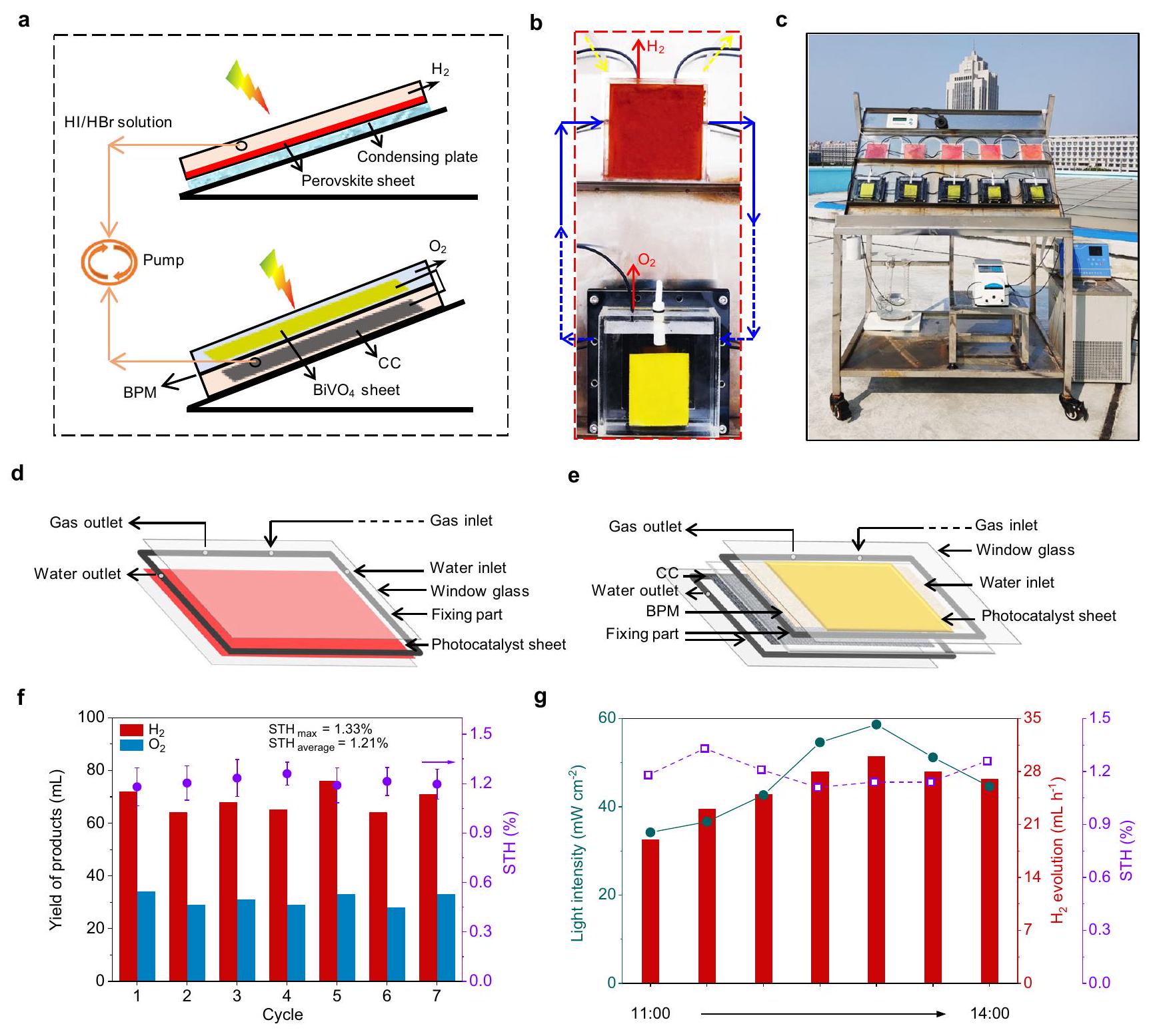
Fig. 6 | Panel system for large-scale outdoor water splitting. a Schematic diagram of a tandem unit for water splitting. Enlarged view of a water-splitting tandem unit including a HER cell and an OER cell. The upper red sheet is a MoSe / film ( ), and the lower yellow sheet is a NiFe-LDH/BiVO film ( ). c Image of the outdoor large-scale experimental module of tandem solar-driven overall water splitting system (5 units). Structural layout of HER subreactor (d) and OER sub-reactor (e). The yield of products and the corresponding STH of one unit system. Each cycle is . These data were collected at
the State Key Laboratory of Crystal Materials, Shandong University, located in Jinan, China . The period of data collection spanned from 27th October to 2nd November 2023. Error bars for STH efficiency correspond to s.d., based on 7 samples taken at different time points between 11:00 and 14:00 on the same day. Source data are provided as a Source Data file. evolution rate, STH, and light intensity dependence plots were recorded on the day with the highest STH, 29th October 2023.
reduction in two adjacent chambers interconnected by a bipolar membrane (Supplementary Fig. 11). It should be note that, in nowadays reported photocatalytic HI splitting systems , the addition of is indispensable in order to selectively reduce to , because the produced could interfere with the light absorption of the photocatalyst, and it was proved that the photogenerated holes by perovskite are only consumed by without direct oxidation . In this work, we resolve this long-standing challenging problem and remove from the photocatalytic evolution solution by building an integrated flow system. As shown in Fig. 5a, of is evolved within the initial 30 min over under simulated sunlight illumination ( 1 sun, ) even in the absence of , corresponding to an STH of
(obtained from 3 independent measurements). However, the photocatalytic hydrogen evolution rate decreases slightly as the reaction progresses due to the increasing concentration of oxidant , which interferes with the light absorption of the photocatalyst. The obtained -rich acid solution is afterward employed to conjugate with the photocatalytic OER, during which the is reduced and recovered to .
To facilitate OER, a BiVO film is first grown on an FTO glass substrate, and then NiFe-LDH is loaded on the film as the cocatalyst for evolution to improve the charge separation and provide active sites for water-to- conversion . XRD patterns of and NiFe-LDH/BiVO (Supplementary Fig. 12) show the structure of the has no obvious change after loading with NiFe-LDH. NiFeLDH evenly wraps the worm-like , as seen in SEM images
(Supplementary Fig. 13). Furthermore, the elements of Bi, V, O, Ni and Fe are uniformly distributed as obtained from the SEM-mapping (Supplementary Fig. 14). The EDS results of element contents, as shown in Supplementary Table 6, reveal that the mass ratios of Ni and Fe in are estimated at and , respectively. In the OER block, photogenerated electrons in transfer to the linked carbon cloth, which is located in the adjacent chamber filled with the acid solution for reduction, leaving the photogenerated holes migrating to the NiFe-LDH sites for evolution. Such a design can completely suppress the back reaction (the recombination of evolved and from water) and side reaction (the oxidation of on ). The photocatalytic performance for iodine reduction is monitored by an electrochemical workstation but without adding an external bias (Supplementary Fig. 15). After a 1.9-h photo-reaction, 88.6 of the that was produced during the 2-h HER over MoSe FPBI is reduced (Supplementary Fig. 16). The photocurrent between the NiFe and carbon cloth decrease to a bottoming value of ca. (Fig. 5b), and the dark brown-red solution finally turns faint yellow, as shown in the inserted photos in Fig. 5b. The evolved during this expriment is . As a result, via the whole reaction involving two compartments for HER and OER bridged by the redox shuttle, stoichiometric and are separately produced and collected via solar-driven overall water splitting. The STH is calculated as (obtained from 3 independent measurements), which is among the top ranges in reported photocatalytic overall water splitting systems (Supplementary Table 7) . The reason for the slightly gradual decrease of production as the test cycles go on (Fig. 5c) is that this water-splitting experiment is performed in a twostep way, in each cycle after 2 h ‘s photocatalytic HER, the powder photocatalyst is recycled from the -rich acid solution by centrifugation, and then reused. During these operations, there are unavoidable losses of the photocatalyst. Additionally, during the OER and reduction process, only about of the is reduced. This results in a slightly higher ratio of than 2 . To optimize the generation by the HER, we extend the duration of the iodine reduction experiment. As shown in Supplementary Fig. 17, increasing the photoreduction time from 2 h to 4 h enhances the reduction of from to . However, despite this increase, the STH for this experiment decreases from to due to the prolonged exposure to light irradiation. Consequently, it is crucial to rationally optimize the reaction times for both the and OERs to maximize the STH. Furthermore, the AQE of OER for NiFe-LDH/BiVO4 is determined as at 420 nm (Supplementary Fig. 18), which is much lower than that of HER for ( at 420 nm , Fig. 4b). The STH of the current photocatalytic system could be further improved by employing a more efficient OER photocatalyst than NiFe-LDH/BiVO4.
Panel system for large-scale outdoor water splitting
Photocatalytic systems in panel form have demonstrated great potential for large-scale practical production via water splitting . In our current work, we explore scaling up the aforementioned Z-scheme system for solar-driven water splitting, developing panel reactors with modular components easy to expand. has been prepared in the form of a film, which is feasible for being incorporated in a panel reactor, the key point is the development of perovskite sheets. For this purpose, the halide perovskite is immobilized on an acrylic plastic plate sheet by a facile solution-processed drop-casting method using tetraethyl orthosilicate as the binder agent (Supplementary Fig. 19). The microstructure characterization (Supplementary Fig. 20) shows that the photocatalyst sheet contains perovskite particles of several micrometers in size, with the binder tetraethyl orthosilicate/silica particles forming porous structures available for mass transfer. Such a perovskite photocatalyst sheet ) produces by HI splitting with an STH of in a hydrohalic solution containing under simulated sunlight
illumination (1 sun, AM1.5G, , Supplementary Fig. 21). Furthermore, the photocatalytic HER activity demonstrates an increase with the loading amount of perovskite from 10 to 70 mg on the plexiglass substrate plate, with comparable activity to that of the powder suspension system containing the same amount of photocatalyst (Supplementary Fig. 22). However, beyond 70 mg , the HER activity of the perovskite sheets no longer exhibits a significant increase with further addition of the photocatalyst, reaching a stable level. This is probably because the exposure of active sites tends to be saturated on a specific substrate with a limited area (with the maximum effective loading amount of photocatalyst of ca. ). In contrast, the suspension system with more liquid solution under stirring could enable more photocatalysts, and that is why a higher photocatalytic activity is obtained in the suspension system with larger amounts of photocatalysts ( ) (Fig. 4a, Supplementary Fig. 22). However, the photocatalyst sheets greatly reduces the amount of required reactant solution and eliminates the demand for an additional stirring system, which is indispensable in suspension systems. These advantages are beneficial for the development and promotion of scaled-up applications of photocatalytic systems.
The designed reactor for large-scale tests consists of tandem HER and OER cells (sub-reactors), which are connected and circulated by a peristaltic pump, allowing the oxidation product of in the acidic HER cell to flow into the OER cell, as well as the reduced I- to flow back to the HER cell, as is schematically shown in Fig. 6a. As for the HER subreactor, the compartment is composed of a bottom plate and a same-size plexiglass cover window, with the acid solution layer depth (i.e., the space height of the reactor) of 3 mm (Fig. 6d). The perovskite sheet is readily extendable to a larger area through the solution-processing drop-casting method. For example, a photocatalyst film is availably prepared on the plexiglass bottom plate of the panel reactor (Supplementary Fig. 23). Then, the performance of the HER reactor incorporated with the perovskite sheet was evaluated at outdoor conditions (from 13:00 to 15:00, Shandong University, ) under sunlight, and was evolved in 2 h in the acid solution without at atmospheric pressure (Supplementary Fig. 24). On the other hand, a film is connected with a carbon cloth to assemble an OER cell covered with a plexiglass window (Fig. 6e). This OER compartment is divided into two chambers by a bipolar membrane for reduction and evolution accomplished by carbon cloth and , respectively.
A 7-day outdoor test (from 11:00 to 14:00 each day) was conducted at the State Key Laboratory of Crystal Materials, Shandong University ( ) under natural light illumination. Five module units ( FPBI, Fig. 6b shows the enlarged view of one unit) were integrated for a scale-up exemplification (in principle, an arbitrary desired number of units could be integrated, provided that the peristaltic pump can supply sufficient driving force for the circulation), as shown in Fig. 6c and Supplementary Fig. 25. The gas production output from the system are and for HER and OER, respectively (Supplementary Fig. 26), demonstrating a net reaction of overall water splitting without the addition of sacrificial reagent. The panel system achieves an average STH of (Fig. 6f, Supplementary Fig. 27). The highest STH value of was obtained on October 2023, at 11:30 am when the intensity of sunlight was (Fig. 6g and Supplementary Movie 2). This value is half of that in the powder suspension system because the maximum effective photocatalyst loading on the plate substrate ( ) limits its photocatalytic activity (Supplementary Fig. 22). Furthermore, the uniformity and quality of the perovskite film with a larger area ( ) maybe not as so good as that in a smaller sheet , as shown in Supplementary Fig. 23. Another associated problem in this scale-up system is that, upon the photocatalytic reaction going on, the perovskite film
peels off to some degree from the substrate (Supplementary Fig. 28), causing the degradation of the panel structure. To enhance performance, modifications are essential in the selection of a suitable binder agent, substrate and coating method. These adjustments would increase the effective loading amount of perovskite on the substrate and ensure a more intimate contact, thereby enhancing activity and stability. Additionally, detailed work is needed for future system optimizations. For example, the concentration of the redox mediator, which is a factor affecting the STH efficiency of the outdoor system, needs careful management. This concentration can be controlled by adjusting the liquid flow in a peristaltic pump.
Regardless of the design chosen for solar fuel devices, several key constraints must be considered for practical applications, including fundamental requirements for efficiency, stability, cost, and scalability. Although the STH efficiency of our device is currently lower than that of photovoltaic-driven electrolysis for overall water splitting at the lab scale, our device demonstrates advantages in simplicity, costeffectiveness and scalability (Supplementary Table 8). Most importantly, the unique design of our photocatalytic Z-scheme system not only produces and in separate cells but also effectively suppresses side and back reactions, resulting in notably improved STH for Z -scheme systems. This approach offers valuable insights to address current challenges in Z-scheme systems and would accelerate advancements toward higher efficiencies.
In summary, this work demonstrates an integrated efficient solardriven Z-scheme overall water-splitting system incorporating two cells for HER and OER, respectively, connected by the redox mediator. This design achieves separated and evolution from water, suppressing the reverse reactions and side reactions commonly happening in conventional Z-scheme photocatalytic systems and avoiding the complicated gas storage and post-separation processes associated with the safety problems. Therefore, the current archives an STH of under 1 sun simulation (AM1.5G, ). Additionally, the designed system and panel reactor modules are readily available for tandemly scaling up. This work demonstrates that the unique design of the reaction system opens valuable opportunities for enhancing the efficiency of solar-driven overall water-splitting systems.
Methods
Preparation of formamidinium bromide (FABr)
FABr was synthesized through a double replacement reaction as we reported previously . Specifically, 5 g of formamidine acetate ( , Aladdin., ) was slowly added to 7.5 mL of hydrobromic acid ( HBr , Aladdin., in water) with stirring to form a cleared solution and heated at until the solvent was completely removed. The obtained white powder was washed with 15 mL ether (Sinopharm Chemical Reagent Co., Ltd., AR, ) and dried at room temperature to obtain FABr .
Preparation of perovskite photocatalysts and solutions for photocatalytic reactions
The powders were synthesized by a saturated solution coprecipitation method. Typically, 10 g lead bromide ( , Aladdin., 99%) was dissolved in 50 mL mixed solutions of HBr acid and hypophosphorous acid ( , Shanghai Macklin Biochemical Co., Ltd., AR, in water) ( ), then 3.41 g FABr was slowly added into the solution with vigorous stirring under . The solution and powders were separated by centrifugation, obtaining the FPB powders and FPB-saturated acid solution. Then, the obtained acid solution was mixed with 3 mL hydriodic acid (HI, Aladdin., 55-58%), followed by the addition of 0.5 g FPB powders with vigorous stirring. The mixture was exposed to simulated sunlight irradiation for 2 h to accelerate the halogen exchange reaction and obtain the mixed-halide perovskite of . The powder sample
of FPBI was separated from its solution by centrifugation and dried at in an oven. The obtained acid solution saturated with FPBI was preserved as the reaction solution in subsequent photocatalytic tests. In the experiments designed to investigate the photocatalytic activity of the perovskite photocatalyst in solutions without , the corresponding perovskite-saturated acid solution was prepared following similar procedures to those previously described, with the exception that was not added to the acid solution.
Preparation of nanoflowers
nanoflowers were synthesized via a solvothermal process . First, 0.484 g sodium molybdate dihydrate , Aladdin., sodium borohydride , Sinopharm Chemical Reagent Co., Ltd., AR) and 0.316 g selenium powder (Se, Aladdin., 99.9%) were added to a beaker containing 40 mL ethanol solution, and the solution was heated to . After vigorous stirring for 2 h , the solution was transferred to a 100 mL Teflon-lined autoclave and maintained at for 24 h . After cooling to room temperature, the black powders obtained through suction filtration were dried in a vacuum oven at to get the final product.
Preparation of
/FPBI was prepared by an electrostatic self-assembly approach. Specifically, the as-synthesized FPBI powder and nanoflowers ( ) were added into a 50 mL beaker containing 30 mL FPBI saturated solution. After stirring for FPBI precipitate was obtained by electrostatic adsorption of on the surfaces of FPBI.
Preparation of photocatalyst film
The photocatalyst film was prepared on the plexiglass bottom plate via a facile solution-processed drop-casting method using tetraethyl orthosilicate (Ecopower New Materials Co., Ltd., Crosile-Si 28) as the binder agent. Firstly, the plexiglass was cleaned with ethanol and DI water. 70 mg of the prepared FPBI was then dissolved in 1 mLN ,N-Dimethylformamide (DMF, Shanghai Macklin Biochemical Co., Ltd., AR, ). Subsequently, and 10 uL tetraethyl orthosilicate binder were added and dispersed by sonication for 10 min . Dropped the solution to the plexiglass bottom plate uniformly, then transferred the plate to an oven at for 24 h .
Preparation of film
The film was fabricated using a method reported in previous literature . Initially, 6.640 g of potassium iodide (KI, FUJIFILM Wako Pure Chemical Corporation, ) and 1.940 g of bismuth nitrate pentahydrate , FUJIFILM Wako Pure Chemical Corporation, ) were dissolved in 100 mL deionized water. To adjust the of nitric acid ( , KANTO CHEMICAL CO., INC., ) was added and the mixture was stirred for 40 min . In parallel, 40 mL of ethanol containing 0.994 g of p-benzoquinone (KANTO CHEMICAL CO., INC., 98%) was stirred for 30 min . The ethanol solution was then added to the water solution and stirred for an additional 30 min , forming a mixed solution. The BiOI film was synthesized through electrodeposition in a standard three-electrode setup using a CHI 660E electrochemical workstation. A cleaned FTO glass substrate (FTO, , with an immersed area of ) was employed as the working electrode. A saturated electrode served as the reference electrode, while a Pt sheet was employed as the counter electrode. An anodic deposition was performed at a constant voltage of -0.1 V for 10 min to produce BiOI. Subsequently, 0.45 mL of a dimethyl sulfoxide (DMSO, KANTO CHEMICAL CO., INC., 99%) solution containing 0.2 M vanadyl acetylacetonate ( , Sigma-Aldrich, 98%) was applied to the BiOI nanosheets. These were then put in a muffle furnace and heated at for 2 h . Finally, the film was obtained by immersing the
obtained product in 1 M sodium hydroxide ( NaOH , Sigma-Aldrich, ) for 30 min .
Preparation of NiFe-LDH/ film
NiFe-LDH was modified onto film according to a hydrothermal method reported previously with some adjustments . Specifically, 10 mg iron nitrate nonahydrate , Aladdin., AR and 45 mg nickel nitrate hexahydrate , Sinopharm Chemical Reagent Co., Ltd., AR, ) were typically dissolved in 24 mL DI water and 6 mL DMF (Shanghai Macklin Biochemical Co., Ltd., AR, ). Subsequently, the film was immersed in this solution with stirring for 30 min . The as-prepared sample was put into Teflonlined autoclaves for the solvothermal reaction to for 6 h . The film was obtained after cleaning with deionized water and ethanol.
Characterization
The crystal structures were analyzed by X-ray diffraction (XRD) using a Rigaku MiniFlex 600 instrument. Surface morphologies were examined via scanning electron microscope (SEM) (Hitachi S-4800), while detailed nanostructures were studied using a transmission electron microscope (TEM) and high-resolution TEM (HR-TEM) (JEOL JEM2100F). X-ray photoelectron spectroscopy (XPS) spectra were recorded on a Thermo Scientific ESCALAB Xi+ spectrometer. Optical absorption properties were investigated using ultraviolet-visible diffuse reflectance spectroscopy (UV-vis DRS) with a Shimadzu UV-2600 spectrophotometer. Single particle PL images and spectra were captured using an objective scanning confocal microscope system (PicoQuant, MicroTime 200) paired with an Olympus IX71 inverted fluorescence microscope. The excitation was performed using a 405 nm laser with a typical excitation power of . Photoelectrochemical measurements were carried out in a standard threeelectrode electrochemical system using a CHI 660E electrochemical workstation in dichloromethane containing 0.05 M tetrabutylammonium hexafluorophosphate (TBAPF ). On-off photocurrent responses and EIS were conducted at 0.5 V versus using a 300 W Xe lamp with an AM 1.5G filter as the light source, also on a CHI 660E electrochemical workstation.
Photocatalytic evolution measurements
The photocatalytic evolution experiments were performed in aqueous acid solutions saturated with the perovskite solute, inside a top-irradiation vessel (reactor diameter: 2 cm , irradiation area: , unless otherwise stated), which was connected to a glass-enclosed gas circulation system. A 300 W Xe-lamp (CELHXF300) with an AM 1.5 G filter served as the light source, and its intensity was calibrated to using an optical power meter (PL-MW2000). For the powder suspension system, 100 mg of photocatalyst was mixed with 10 mL of acid solution saturated with the perovskite solute while stirring continuously. For the photocatalytic testing of a perovskite film, the photocatalyst sheet deposited on an acrylic plastic plate was placed at the bottom of a glass cylindrical reactor (diameter: 7.2 cm ) containing 50 mL of acid solution. The comparison between the smaller ( ) and larger ( ) perovskite sheets was conducted in a panel reactor under natural outdoor conditions with sunlight irradiation. The reactions were performed at a background pressure of 1 kPa and cooled using circulating water at , unless otherwise stated.
The amounts of evolved gas were analyzed using a gas chromatograph (ShiweipxGC-7806) with argon as the carrier gas. To assess the stability of the photocatalyst, a cycling photocatalytic test was carried out every 3 h for 20 cycles, with re-evaluation after each cycle. The AQE was measured using the same 300 W Xe-lamp equipped with a band-pass filter and the photon flux of the incident light was determined using a PL-MW2000 spectroradiometer. The
AQE for photocatalytic HI splitting was calculated using the following equation:
STH efficiency of photocatalytic HI splitting: The standard hydrogen reduction potential and the oxidation potential to are O and 0.53 V (versus NHE), respectively. Using the Nernst equation and the required ion concentration of ( , Supplementary Fig. 29), the cell potentials of the reactions and were calculated to be 0.056 V and 0.437 V versus NHE, respectively, yielding a potential for HI splitting of 0.381 V . The STH efficiencies were estimated using the following equation:
Laboratory evaluation on photocatalytic overall water splitting Overall water splitting conducted on a laboratory scale was realized in a two-step reaction way. First, the photocatalytic HER was conducted in the acid solution without was added to 10 mL of solution saturated with FPBI solute for 2 h of proton reduction and oxidation experiments (AM 1.5 G , ). Subsequently, the -rich solution obtained by the HER process was separated from the perovskite photocatalyst by centrifugation, and transferred to be used as the electron acceptorcontaining solution to combine with the OER in an H-type cell interconnected by a bipolar membrane (Fumasep FBM, with the working area of ). Specifically, a NiFe film was used as the OER photocatalyst in a 0.5 M potassium borate solution , with a wireconnected carbon cloth (CC, ) immersed in the -rich acid solution in the other adjacent chamber. Simulated sunlight (AM 1.5 G, ) provided by a 300 W Xe lamp equipped with an AM1.5 filter was used as the light source. Under illumination, photogenerated electrons in transferred to the linked CC for reduction, leaving the photogenerated holes migrating to the surficial NiFe-LDH sites for evolution. After the reduction of to , the color of the perovskite-saturated solution turned to transparent shallow yellow, and this solution was used to conduct a new round of photocatalytic production tests. Before the experiment, was bubbled through the reactants for half an hour to remove the dissolved . The reactions operated at a background pressure of 1 kPa and were cooled using circulating water at unless otherwise stated. The amounts of evolved gas were analyzed by a gas chromatograph (ShiweipxGC-7806) with Ar as the carrier gas.
The STH of photocatalytic overall water splitting was calculated from the standard redox potential of oxidation and the reduction potential, using the following equation:
Note that, the energy input, either manual or equipment-related, such as the centrifuge, for the separation and transfer of the acid solution between the HER and OER cells, is neglected here.
Photoelectrochemical tests for reduction and production The photoelectrochemical measurements were performed on the CHI 660E electrochemical workstation and in a conventional two-electrode system with a bipolar membrane (BPM, Fumasep FBM, with a working area of ) to separate the OER cell with the -reduction cell. The bipolar membrane was selected because it allowed the and dissociated from water at the interface of the exchange layer to migrate to the acidic HER and alkaline OER sides, respectively, making it more suitable for water splitting in the current system than a proton exchange membrane.
A 300 W Xe lamp coupled with an AM1.5G filter was used as the light source. The photoanode was the NiFe-LDH/BiVO , and the electrolyte was 0.5 M KBi . The electrode in photocathode compartment was the , and the electrolyte was the perovskite-saturated solution (containing rich , ) after the photocatalytic production reaction. The long-term photoelectrochemical reduction and production experiment was implemented at 0 V .
Outdoor large-scale photocatalytic system modules
The outdoor panel reactor included tandem HER and OER cells (subreactors), which were connected and circulated by a peristaltic pump. As for the HER sub-reactor, the compartment was composed of a bottom plate and a same-size plexiglass cover window, with the acid solution layer depth (i.e., the space height of the reactor) of 3 mm . The photocatalytic film was prepared by the same method as that of the sample. The bottom plate was coated with the photocatalytic film, fixing part and plexiglass cover window were sealed via a strong adhesive. The OER sub-reactor was divided into two chambers by a bipolar membrane containing a NiFe film and a , respectively, which were connected by wires to transmit photogenerated electrons. The volumes of the NiFe-LDH/BiVO chamber and CC chamber were and , respectively, and the reactor material was the same as the HER sub-reactor. A bipolar membrane with a working area of ) was used to separate these two chambers. The plexiglasses and fixing parts were sealed using a strong adhesive, and the two chambers were secured with screws.
Each chamber was fitted with a rubber ring between it and the bipolar membrane to ensure the sealing of the reactor. A HER subreactor and an OER sub-reactor connected by a peristaltic pump form a modular unit. Five modular units were integrated as a demonstration (in principle, the arbitrary desired number of units can be integrated if only the peristaltic pump provides enough driving force for the circulation of liquids). and produced by the reaction were collected separately by the drainage method. Gas/ liquid inlet/outlet pipes were made of acid-resistant rubber hose (outer diameter 3 mm , inner diameter 2 mm ). A 7 -day outdoor test was conducted at the State Key Laboratory of Crystal Materials (Shandong University, Jinan, China, . 27th October-2nd November 2023) under natural light illumination. The sunlight during the outdoor test days was not strong, with an average light intensity of only about even at midday. At earlier and later times, the light intensity was even lower, resulting in remarkably reduced photocatalytic production. In some instances, the collected gases were negligible. Therefore, in the article, we present the data only from 11:00 to 14:00. The calculation of STH for the outdoor photocatalytic test was the same as the photocatalytic overall water splitting, based on the amounts of evolved and out-door and detected intensity of sunlight, with the irradiation area being the sum of the film ( ) and the NiFe film ( ), as . The molar amounts of gases were calculated based on the ideal gas law under standard state.
Data availability
All data are available in the main text and the supplementary information, and are provided in the Source Data file. Source data are provided with this paper.
References
Schultz, D. M. & Yoon, T. P. Solar synthesis: prospects in visible light photocatalysis. Science 343, 1239176 (2014).
Lewis, N. S. Research opportunities to advance solar energy utilization. Science 351, aad1920 (2016).
Kim, J. H., Hansora, D., Sharma, P., Jang, J.-W. & Lee, J. S. Toward practical solar hydrogen production-an artificial photosynthetic leaf-to-farm challenge. Chem. Soc. Rev. 48, 1908-1971 (2019).
Zhou, P. et al. Solar-to-hydrogen efficiency of more than in photocatalytic water splitting. Nature 613, 66-70 (2023).
Wang, Q. & Domen, K. Particulate photocatalysts for light-driven water splitting: mechanisms, challenges, and design strategies. Chem. Rev. 120, 919-985 (2020).
Teitsworth, T. S. et al. Water splitting with silicon p-i-n superlattices suspended in solution. Nature 614, 270-274 (2023).
Tao, X., Zhao, Y., Wang, S., Li, C. & Li, R. Recent advances and perspectives for solar-driven water splitting using particulate photocatalysts. Chem. Soc. Rev. 51, 3561-3608 (2022).
Wang, Z., Li, C. & Domen, K. Recent developments in heterogeneous photocatalysts for solar-driven overall water splitting. Chem. Soc. Rev. 48, 2109-2125 (2019).
Bie, C., Wang, L. & Yu, J. Challenges for photocatalytic overall water splitting. Chem 8, 1567-1574 (2022).
Suzuki, H., Nitta, S., Tomita, O., Higashi, M. & Abe, R. Highly dispersed hydrates prepared via simple adsorption as efficient cocatalysts for visible-light-driven Z-scheme water splitting with an redox mediator. ACS Catal. 7, 4336-4343 (2017).
Maeda, K., Higashi, M., Lu, D., Abe, R. & Domen, K. Efficient nonsacrificial water splitting through two-step photoexcitation by visible light using a modified oxynitride as a hydrogen evolution photocatalyst. J. Am. Chem. Soc. 132, 5858-5868 (2010).
Abdul Nasir, J. et al. Photocatalytic Z-scheme overall water splitting: recent advances in theory and experiments. Adv. Mater. 33, 2105195 (2021).
Wang, Y. et al. Mimicking natural photosynthesis: solar to renewable fuel synthesis by Z-scheme water splitting systems. Chem. Rev. 118, 5201-5241 (2018).
Wang, Q. et al. Scalable water splitting on particulate photocatalyst sheets with a solar-to-hydrogen energy conversion efficiency exceeding 1. Nat. Mater. 15, 611-615 (2016).
Hisatomi, T. & Domen, K. Reaction systems for solar hydrogen production via water splitting with particulate semiconductor photocatalysts. Nat. Catal. 2, 387-399 (2019).
Chen, S., Li, C., Domen, K. & Zhang, F. Particulate metal chalcogenides for photocatalytic Z-scheme overall water splitting. Joule 7, 2445-2467 (2023).
Qi, Y. et al. Redox-based visible-light-driven Z-scheme overall water splitting with apparent quantum efficiency exceeding 10. Joule 2, 2393-2402 (2018).
Wu, Y. et al. An organometal halide perovskite supported Pt singleatom photocatalyst for evolution. Energy Environ. Sci. 15, 1271-1281 (2022).
Liu, Y. et al. Theoretical calculations and controllable synthesis of -CdSe with highly active sites for photocatalytic hydrogen evolution. Chem. Eng. J. 383, 123133 (2020).
Zeng, D. et al. Construction of network-like and flower-like 2H nanostructures coupled with porous for noble-metal-free photocatalytic evolution under visible light. Appl. Catal. B 233, 26-34 (2018).
Liu, X. et al. Integrating mixed halide perovskite photocatalytic HI splitting and electrocatalysis into a loop for efficient and robust pure water splitting. Adv. Mater. 35, 2208915 (2023).
Zhumekenov, A. A. et al. Formamidinium lead halide perovskite crystals with unprecedented long carrier dynamics and diffusion length. ACS Energy Lett. 1, 32-37 (2016).
Yi, J. et al. Phase and interlayer effect of transition metal dichalcogenide cocatalyst toward photocatalytic hydrogen evolution: the case of MoSe . Appl. Catal. B 243, 330-336 (2019).
Dong, M. et al. nanosheet as noble-metal-free cocatalyst over : optimizing interfacial charge transfer for enhanced photocatalytic hydrogen evolution. Int. J. Hydrog. Energy 48, 26768-26780 (2023).
Wang, Y., Xiao, X., Chen, J., Lu, M. & Zeng, X. 1T phase boosted with Z-scheme heterojunction for enhanced photocatalytic degradation of contaminants. Appl. Surf. Sci. 510, 145341 (2020).
Hadland, E. C. et al. Synthesis and properties of (BiSe) : a heterostructure containing both and . Chem. Mater. 31, 5824-5831 (2019).
Cheng, C. et al. Facile preparation of nanosized MoP as cocatalyst coupled with by surface bonding state for enhanced photocatalytic hydrogen production. Appl. Catal. B 265, 118620 (2020).
Zhang, Y., Liu, J., Zhang, Y. & Bi, Y. Relationship between interatomic electron transfer and photocatalytic activity of . Nano Energy 51, 504-512 (2018).
Li, N. et al. Stable multiphasic nanosheets integrated with 1D sulfide semiconductor for drastically enhanced visible-light photocatalytic hydrogen evolution. Appl. Catal. B 238, 27-37 (2018).
Yang, X. et al. Mechanistic insights into charge carrier dynamics in heterojunctions for boosted photocatalytic hydrogen evolution. Mater. Today. Phys. 15, 100261 (2020).
David, P. et al. A mixed-cation lead mixed-halide perovskite absorber for tandem solar cells. Science 351, 151-155 (2016).
Michael, C. B., Sergiu, D., Prashant, V. K. & Masaru, K. Light-induced anion phase segregation in mixed halide perovskites. ACS Energy Lett. 3, 204-213 (2018).
Luo, J. et al. Bipolar membrane-assisted solar water splitting in optimal pH. Adv. Energy Mater. 6, 1600100 (2016).
Vargas-Barbosa, N. M., Geise, G. M., Hickner, M. A. & Mallouk, T. E. Assessing the utility of bipolar membranes for use in photoelectrochemical water-splitting cells. ChemSusChem 7, 3017-3020 (2014).
Vermaas, D. A., Sassenburg, M. & Smith, W. A. Photo-assisted water splitting with bipolar membrane induced pH gradients for practical solar fuel devices. J. Mater. Chem. A. 3, 19556-19562 (2015).
Zhao, Z. et al. -decorated as visible-light photocatalyst for evolution from HI splitting. ACS Catal. 9, 8144-8152 (2019).
Wang, X. et al. Dynamic interaction between methylammonium lead iodide and nanocrystals leads to enhanced photocatalytic evolution from HI splitting. ACS Energy Lett. 3, 1159-1164 (2018).
Guan, W. et al. Fabricating composites for improved photocatalytic performance. Nano Lett. 21, 597-604 (2021).
Park, S. et al. Photocatalytic hydrogen generation from hydriodic acid using methylammonium lead iodide in dynamic equilibrium with aqueous solution. Nat. Energy 2, 16185 (2016).
Wu, Y. et al. Composite of with reduced graphene oxide as a highly efficient and stable visible-light photocatalyst for hydrogen evolution in aqueous HI solution. Adv. Mater. 30, 1704342 (2018).
Boppella, R., Choi, C. H., Moon, J. & Ha Kim, D. Spatial charge separation on strongly coupled 2D-hybrid of rGO/La2 LDH heterostructures for highly efficient noble metal free photocatalytic hydrogen generation. Appl. Catal. B 239, 178-186 (2018).
Liu, Y. et al. Enhancing the photoelectrochemical water oxidation activity of thin film photoanode by employing rGO as electron transfer mediator and NiFe-LDH as cocatalyst. ChemCatChem 13, 4729-4737 (2021).
Yan, J., Zhang, X., Zheng, W. & Lee, L. Y. S. Interface engineering of a 2D- -LDH heterostructure for highly efficient
photocatalytic hydrogen evolution. ACS Appl. Mater. Inter. 13, 24723-24733 (2021).
Guo, F. et al. Deprotonation of with Na ions for efficient nonsacrificial water splitting under visible light. J. Mater. Chem. A. 4, 10806-10809 (2016).
Wang, Q. et al. Particulate photocatalyst sheets based on carbon conductor layer for efficient Z-scheme pure-water splitting at ambient pressure. J. Am. Chem. Soc. 139, 1675-1683 (2017).
Sun, S. et al. Efficient redox-mediator-free Z-scheme water splitting employing oxysulfide photocatalysts under visible light. ACS Catal. 8, 1690-1696 (2018).
Chen, X . et al. Three-dimensional porous for highly efficient photocatalytic overall water splitting. Nano Energy 59, 644-650 (2019).
Song, X. et al. Overall photocatalytic water splitting by an organolead iodide crystalline material. Nat. Catal. 3, 1027-1033 (2020).
Takata, T. et al. Photocatalytic water splitting with a quantum efficiency of almost unity. Nature 581, 411-414 (2020).
Zhao, D. et al. Boron-doped nitrogen-deficient carbon nitride-based Z-scheme heterostructures for photocatalytic overall water splitting. Nat. Energy 6, 388-397 (2021).
Nishioka, S. et al. Surface-modified, dye-sensitized niobate nanosheets enabling an efficient solar-driven Z-scheme for overall water splitting. Sci. Adv. 8, eadc9115 (2022).
Yang, Y. et al. Engineering beta-ketoamine covalent organic frameworks for photocatalytic overall water splitting. Nat. Commun. 14, 593 (2023).
Zhang, Y. et al. Internal quantum efficiency higher than achieved by combining doping and quantum effects for photocatalytic overall water splitting. Nat. Energy 8, 504-514 (2023).
Xin, X. et al. Large electronegativity differences between adjacent atomic sites activate and stabilize for efficient photocatalytic overall water splitting. Nat. Commun. 15, 337 (2024).
Goto, Y. et al. A particulate photocatalyst water-splitting panel for large-scale solar hydrogen generation. Joule 2, 509-520 (2018).
Nishiyama, H. et al. Photocatalytic solar hydrogen production from water on a 100-m² scale. Nature 598, 304-307 (2021).
Zhang, Q. et al. Composite of formamidinium lead bromide perovskite with reduced graphene oxide (rGO) for efficient evolution from HBr splitting. J. Colloid Interf. Sci. 664, 809-815 (2024).
Li, H., Hao, X., Gong, H., Jin, Z. & Zhao, T. Efficient hydrogen production at a rationally designed p-n heterojunction. J. Colloid Interf. Sci. 586, 84-94 (2021).
Kim, T. W. & Choi, K. S. Nanoporous photoanodes with duallayer oxygen evolution catalysts for solar water splitting. Science 343, 990-994 (2014).
Shi, Y., Yu, Y., Liang, Y., Du, Y. & Zhang, B. In situ electrochemical conversion of an ultrathin tannin nickel iron complex film as an efficient oxygen evolution reaction electrocatalyst. Angew. Chem. Int. Ed. 58, 3769-3773 (2019).
Li, C., Juarez-Perez, E. J. & Mayoral, A. Atomic-level understanding of a formamidinium hybrid halide perovskite, . Chem. Commun. 58, 12164-12167 (2022).
Acknowledgements
This work was financially supported by the Natural Science Foundation of Shandong Province (ZR2O22ZD25 (to P.W.), ZR2O2OQB058 (to Y.W.)), the National Natural Science Foundation of China (22302111 (to Y.W.), 22072071 (to P.W.)), the National Key Research and Development Program of China (2020YFA0710301 (to B.H.)), Artificial Photosynthesis Project of the New Energy and Industrial Technology Development Organization (NEDO) (to Q.W., K.D. and Y.W.) and the JST Fusion Oriented Research for disruptive Science and Technology Program (GAN JPMJFR213D (to Q.W.)).
Author contributions
P.W. conceived the idea. P.W., Q.W., and K.D. designed the project and supervised the work. H.F., Y.W., Y.G., and T.S. conducted synthesis experiments. H.F., Y.W., and Y.G. conducted the majority of the characterizations and photocatalytic reactions. Z.Z. performed the single particle PL characterization. Q.Z., Y.L., Z.Z., H.C., Z.W., and B.H. participated in the discussion and analysis of experimental results. H.F. and Y.W. wrote the manuscript with inputs from Q.W., K.D., and P.W.
Correspondence and requests for materials should be addressed to Qian Wang, Kazunari Domen or Peng Wang.
Peer review information Nature Communications thanks the anonymous reviewer(s) for their contribution to the peer review of this work. A peer review file is available.
Publisher’s note Springer Nature remains neutral with regard to jurisdictional claims in published maps and institutional affiliations.
Open Access This article is licensed under a Creative Commons Attribution-NonCommercial-NoDerivatives 4.0 International License, which permits any non-commercial use, sharing, distribution and reproduction in any medium or format, as long as you give appropriate credit to the original author(s) and the source, provide a link to the Creative Commons licence, and indicate if you modified the licensed material. You do not have permission under this licence to share adapted material derived from this article or parts of it. The images or other third party material in this article are included in the article’s Creative Commons licence, unless indicated otherwise in a credit line to the material. If material is not included in the article’s Creative Commons licence and your intended use is not permitted by statutory regulation or exceeds the permitted use, you will need to obtain permission directly from the copyright holder. To view a copy of this licence, visit http:// creativecommons.org/licenses/by-nc-nd/4.0/.
(c) The Author(s) 2025
State Key Laboratory of Crystal Materials, Institute of Crystal Materials, Shandong University, Jinan, China. Graduate School of Engineering, Nagoya University, Nagoya, Japan. Institute for Advanced Research, Nagoya University, Nagoya, Japan. Institute for Aqua Regeneration, Shinshu University, Nagano, Japan. Office of University Professors, The University of Tokyo, Bunkyo-ku, Tokyo, Japan. These authors contributed equally: Hui Fu, Yaqiang Wu. -e-mail: wang.qian@material.nagoya-u.ac.jp; domen@chemsys.t.u-tokyo.ac.jp; pengwangicm@sdu.edu.cn