واجهة تنسيق-اختزال تآزرية لاستخراج اليورانيوم الكهربائي الاختزالي من مياه البحر مع شوائب منخفضة A synergistic coordination-reduction interface for electrochemical reductive extraction of uranium with low impurities from seawater
الاستخراج الكهروكيميائي لليورانيوم من مياه البحر هو استراتيجية واعدة لتوفير الوقود النووي بشكل مستدام، بينما يعاني التقدم الحالي من ترسيب الشوائب. هنا، نقوم بإنشاء واجهة تنسيق-اختزال تآزرية في CMOS@NSF، مما يحقق الاستخراج الكهروكيميائي للون الأسود.منتج من مياه البحر. الكبريت الداخلي في CoMoOS يخصص توزيع الإلكترونات، مما يؤدي إلى تراكم الإلكترونات في مواقع الأكسجين الطرفية لارتباط قوي مع اليورانيوم. في الوقت نفسه، الاتصال السطحي بين CoMoOS ويسرع نقل الإلكترون ويعزز الخصائص الاختزالية. يضمن هذا التفاعل التآزري بين التنسيق والاختزال تشكيل وحفظ اليورانيوم الرباعي التكافؤ، مما يمنع الترسيب المشترك للقلويات في التحول البلوري. من مياه البحر الطبيعية، يظهر CMOS@NSF قدرة استخراج كهروكيميائية قدرهامع الأسودمنتجات صلبة كمنتجات نهائية. يوفر هذا العمل استراتيجية فعالة لاستخراج اليورانيوم الكهربائي من مياه البحر مع شوائب منخفضة.
لقد استهلكت تطوير واستخدام الطاقة النووية موارد اليورانيوم بشكل كبير، ومن المتوقع أن تنفد في الخامات الأرضية خلال أقل من قرن.إجمالي كمية موارد اليورانيوم في مياه البحر هو 4.5 مليار طن، وهو ما يعادل تقريبًا ألف مرة من موارد اليورانيوم الموجودة على اليابسة.لذلك، فإن استخراج اليورانيوم من مياه البحر هو الطريق الأكثر وعدًا لتلبية الطلب المتزايد على موارد اليورانيوم.الاستخراج الكهروكيميائي لليورانيوم، الذي يستخدم الكهرباء للتقليللقد حظي باهتمام متزايد باستمرار بسبب القدرة المعززة على الاستخراج الناتجة عن تبلور المنتجات النهائية من اليورانيوم، والحركية المعززة المدفوعة بواسطة المجال الكهربائي، والمقاومة المرتفعة لأيونات التداخل غير الاختزالية.. في الاستخراج الكهروكيميائي لليورانيوم، تعتمد كفاءة الاستخراج بشكل أساسي على مواد الأقطاب، مما يحفز الباحثين على التركيز على تصميم مواد الأقطاب.
مؤخراً، تركزت معظم التقارير على بناء مواقع التنسيق لأيونات اليورانيوم. على سبيل المثال، زو وآخرون.مزيفمصفوفات النانو التي تتميز بوجود روابط M-O-H وفيرة، والتي عملت كمواقع تنسيق قوية لأيونات اليورانيوم، مما عزز بشكل كبير القدرة على استخراج اليورانيوم كهربائيًا. تحت ظروف تركيز اليورانيوم العالي، تم إثبات أن ناتج الاستخراج الكهربائي هو. لين وآخرونمُنشَأمواقع أزواج الأيونات داخل، الذي ارتبط بشكل انتقائي معمن خلال متكاملوربما روابط O-U-O متعددة. خلال
عملية استخراج اليورانيوم، تخضع أنواع اليورانيوم لتحول بلوري منإلىيانغ وآخروناستخدمت مجموعات الأميدوكسيالمواقع النشطة على الحديد-النيتروجين-الكربون (Fe-لإيداع بكفاءةعلى شكلمن خلال عملية كيميائية كهربائية. ومع ذلك، حتى الآن، في تقارير البحث المماثلة، كانت منتجات اليورانيوم المستخرجة كهربائياً باستخدام هذه المواد الكهربية إما تتكون من معادن قلوية أو تم ترسيبها في حالات مختلطة غير مستقرة.استخدام الطريقة الكهروكيميائية للتقليلفي مياه البحر إلى، لا سيما في شكل لم يتم الإبلاغ عنها في الأدبيات، مما ألهم الجهد البحثي الحالي. تركز الدراسات المبلغ عنها على بناء مواقع التنسيق لأيونات اليورانيوم على مواد الأقطاب، مع اعتبار أقل لنقل وربط الإلكترونات والمواقع على القطب، مما أدى إلى ضعف تأثيرات اختزال اليورانيوم لمواد الأقطاب وإعادة أكسدة المنتجات الناتجة عن الاختزال.. خلال الاختزال الكهربائي والترسيب لليورانيوم، عندما يتم اختزال يتعرض لإعادة الأكسدة،قد تشكل أنيونات تحتوي على الأكسجين وتتكاثف بشكل إضافي مع كاتيونات المعادن القلوية، مما يؤدي إلى ظاهرة تحول البلورات. لذلك، فإن دراسة التفاعل التآزري بين مواقع التنسيق ومواقع الاختزال لليورانيوم لتحقيق توليد واستقرار منتجات U(IV) أمر مرغوب بشدة، من أجل تحسين نقاء منتجات الاختزال من خلال الاستخراج الكهربائي لليورانيوم من مياه البحر.
هنا، أبلغنا عن مواقع التنسيق-الاختزال ذات الاتصال العالي على الواجهة فيألياف مع بوليوكسوميتالات-طبقة CoMoOS غير المتبلورة المشتقة (CMOS@NSF) للاستخراج الاختزالي الكهربائي لليورانيوم مع شوائب منخفضة من مياه البحر. أظهر تحليل بنية الامتصاص بالأشعة السينية المتزامنة (XAFS) أن CoMoOS أظهر هيكلًا محليًا مشابهًا لـ، باستثناء أن ذرات الأكسجين الداخلية تم استبدالها بالكبريت، بينما ظلت ذرات الأكسجين الطرفية مكشوفة. أظهرت دراسة الآلية أن جيوب الأكسجين الطرفية في CoMoOS سهلت تنسيق الأكسجين الاستوائي، مما لعب دورًا في “التقاط” اليورانيوم من خلال التنسيق. في الوقت نفسه، كانت ذرات النيكل فيمرتبط كيميائيًا بالأكسجين المحوري فيوعملت كقناة لنقل الإلكترونات لتعزيز اختزال اليورانيوم. حقق واجهة التنسيق-الاختزال التآزري قدرة استخراج قدرهافي 25 لتر من مياه البحر الحقيقية على مدى 24 ساعة. بعد استخراج اليورانيوم الكهربائي،تم تقليصه إلى الأسودمنتجات صلبة ب impurities منخفضة.
النتائج
بناء واجهة تنسيق تقليل تآزري
تم تصنيع واجهة CMOS@NSF للتنسيق-الاختزال التآزري في الموقع عبر طريقة هيدروحرارية من خطوة واحدة (الشكل 1أ). تم تصنيع مواد CMOS@NSF بنسب S:Mo مختلفة عن طريق تغيير كمية مصدر الكبريت (الشكل التوضيحي 1). ومن الجدير بالذكر، كما هو موضح في الشكل التوضيحي 2، أن شكل CMOS@NSF بنسبة S:Mo تبلغ 2:1 يتكون من زهور ميكروية تشبه القنفذ بقطر يبلغ حواليتنمو بكثافة على سطح رغوة النيكل (NF). كشفت رؤية مكبرة لزهرة ميكروية تشبه القنفذ (الشكل 1ب) أن المادة تتكون من هياكل تشبه الإبر ذات سطح خشن وقطر يبلغ حوالي 100 نانومتر، مما يشكل الهيكل العام للقنفذ. نظرًا لأن شكل الزهرة الميكروية الشبيهة بالقنفذ يتميز عادة بوجود مواقع امتصاص أو نشاط تحفيزي وفيرة، تم تحديد هيكل الطور والبنية الإلكترونية لـ CMOS@NSF بنسبة S:Mo تبلغ 2:1 (الشكل التكميلي 3). بعد ذلك، يُشار إلى CMOS@NSF بالمادة التي تحتوي على نسبة S:Mo تبلغ 2:1.
تم تسجيل الأشكال والمكونات البلورية لـ CMOS@NSF باستخدام مجهر الإلكترون الناقل عالي الدقة (HRTEM؛ الشكل 1c والشكل التكميلي 4). كانت الحواف الشبكية مع المسافات بين المستويات 0.179 و 0.284 نانومتر تتوافق مع الوجوه (211) و (110) لـ. بالإضافة إلى التعريف الواضح لـجوهر تمت ملاحظة هيكل قشرة غير متبلور. تم تأكيد الهيكل غير المتبلور للسطح بشكل أكبر في صور HRTEM المكبرة وأنماط حيّز الإلكترون المختار (SAED) (الشكل 1d). كما تم تحديد العناصر Co و Mo و Ni و O و S التي تم توزيعها بشكل موحد على سطح مادة CMOS@NSF باستخدام مجهر الإلكترون الناقل الماسح مع مطياف الأشعة السينية المشتتة بالطاقة (STEM-EDS) (الشكل 1e). وُجد أن الكسر الذري لـ Co و Mo كان 1.21 و 7.15 على التوالي، وكانت نسبة Co:Mo هي 1:5.9 (الجدول التكميلي 1). تم التحقيق في تركيب الطور لـ CMOS@NSF باستخدام حيود الأشعة السينية (XRD) (الشكل 1f والشكل التكميلي 5). يشبه نمط الحيود لـ CMOS@NSF بشكل وثيق ذلك لـتم تحديد مجموعتين من القمم المميزة كمعيار للنيكل المعدني (PDF #04-0850)وسداسي (PDF #44. في الوقت نفسه، أظهر CMOS@NSF انخفاضًا في شدة القمم عند المواقع المميزة للتشتت مقارنة بـبسبب وجود طبقة سطحية غير متبلورة حجبت إشارات الحيود.
تم تحليل الحالة الكيميائية السطحية لـ CMOS@NSF باستخدام مطيافية الأشعة السينية للالكترونات (XPS) ومطيافية الرنين المغناطيسي الإلكتروني (EPR). كانت طيف XPS لكل عنصر في عينات CMOS@NSF ذات نسب S:Mo مختلفة متشابهة، حيث اختلفت فقط في نسب مساحة القمة (الشكل التكميلي 1). أكد طيف المسح XPS لـ CMOS@NSF وجود Co و Mo و Ni و S و O (الشكل التكميلي 6a). في Coطيف، القمم عند طاقات الربط 781.46 و797.14 إلكترون فولت تت corresponded إلى و من. في الموطيف، تم تخصيص القمم عند 232.31 و 235.46 إلكترون فولت لـ (الشكل التوضيحي الإضافي 6c) . القمم عند طاقات الربط 231.50 و 234.62 إلكترون فولت، والتي كانت أعلى من تلك الخاصة بـ ، مما يشير إلى وجود الموليبدينوم في حالة أكسدة متوسطة، . بالإضافة إلى ذلك، تم نسب ذروة عند طاقة ربط تبلغ 226.12 إلكترون فولت إلى. في طيف، تم نسب القمم عند طاقات الربط 856.95 و 874.94 إلكترون فولت إلىتتوافق القمم عند طاقات الربط 855.74 و 873.31 إلكترون فولت مع ميزات الدوران المداري لـ. بالإضافة إلى ذلك، تم تخصيص القمم عند 852.77 و 869.76 إلكترون فولت لـ، تمثل النيكل المعدني في NF (الشكل التوضيحي التكميلي 6d). الـ الطيف كشف عن وجود كل من و (الشكل التوضيحي الإضافي 6e) القمم في و 532.09 إلكترون فولت في الطيف يتوافق مع روابط المعدن-الأكسجين الأكسجين منخفض التنسيق ) ومجموعات الهيدروكسيل من الماء الممتص، على التوالي (الشكل التوضيحي 6f)وجودنُسب إلى تأثير المنشطات للكبريت. أشار طيف EPR (الشكل 1g) إلى أن إشارة مجال المغناطيسية الرنانة لـ CMOS@NSF كانت أقوى بكثير من تلك الخاصة بـالذي تم نسبه إلى وجود عدد كبير من الإلكترونات الزوجية الوحيدة على ذرات الأكسجين ذات التنسيق المنخفض.
تم إجراء مزيد من التحقيق في الروابط والهياكل الإلكترونية للسطح غير المتبلور. تم دراسة اهتزازات الشد لـعند 945 وتمت ملاحظتها في طيف الأشعة تحت الحمراء بتقنية تحويل فورييه (FT-IR) لكل من CMOS@NSF و (الشكل 2أ). قمم الأشعة تحت الحمراء عند 649 ونُسِبَت إلى اهتزازات الشد غير المتناظرة لـ و على التوالي. من الجدير بالذكر أن هناك قمم إضافية مرتبطة بـتمت ملاحظة السندات عند 469,501 وفي الطيف تحت الأحمر لـ CMOS@NSF، مما يؤكد دمج ذرات الكبريتبالإضافة إلى ذلك، فإن اهتزازات الشد غير المتناظرة لـ و عند 649 وعلى التوالي، لم تُلاحظ في طيف CMOS@NSF، والذي تم نسبه إلى تعطيل هيكل الربط الأكسجيني بين ذرات الكوبالت وذرات الموليبدينوم والذرات المحيطة من الموليبدينوم بسبب دمج ذرات الكبريت. في أطياف رامان (الشكل 2ب)، تم ملاحظة قمة جديدة عندفي CMOS@NSF تم نسبه إلى وضع Mo-S، مما يؤكد بشكل أكبر إدخال ذرات الكبريت.. تظهر طيف امتصاص الأشعة السينية بالقرب من حافة O K -edge (XANES) في الشكل 2c قممًا عند 532.1 و 534.5 إلكترون فولت لـ، الذي يتوافق مع و أشرطة التهجين، على التوالي. في CMOS@NSF،
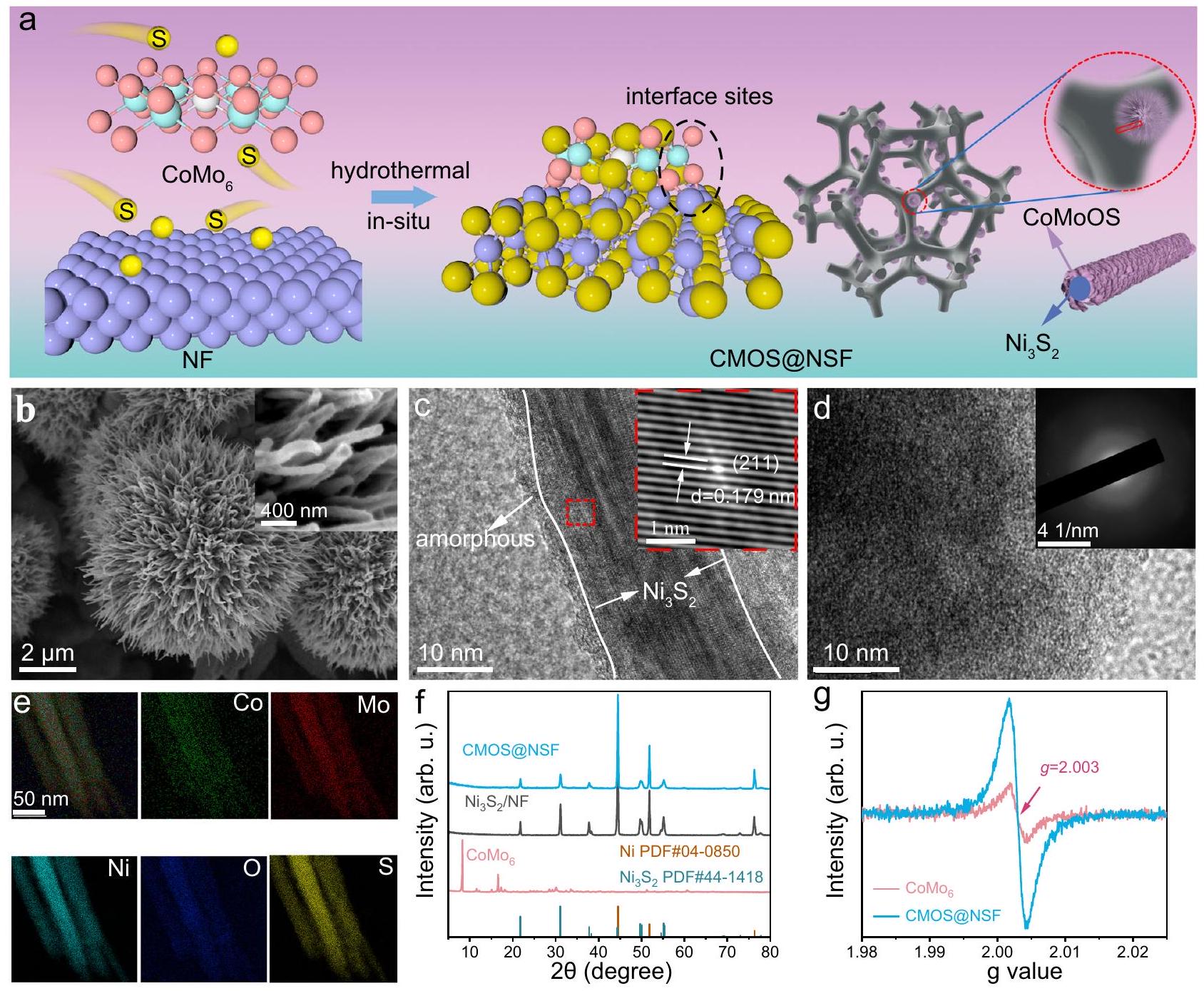
الشكل 1 | بناء مواقع الواجهة. أ مخطط لتخليق المواد بطريقة الهيدروحرارية في خطوة واحدة. ب صور مجهر إلكتروني مسحي لـ CMOS@NSF (الإطار يظهر عرضًا مكبرًا للطرف). ج صور HRTEM لـ CMOS@NSF (الإطار يظهر عرضًا مكبرًا والحواف الشبكية المقابلة). د صور HRTEM للمنطقة غير المتبلورة على سطح CMOS@NSF (الإطار هو المقابل لذلك).
أنماط SAED). خرائط العناصر STEM-EDS لـ Co و Mo و Ni و O وأنماط XRD لـ CMOS@NSF وطيف EPR لـ والمركز الوطني للعلوم. تمثل المناطق المميزة باللون الوردي والبنفسجي والأزرق في الشكل 2a قمة Mo-O، ذروة Ni وذروة Ni-S، على التوالي. يتم توفير بيانات المصدر كملف بيانات المصدر. تم نقل نطاق التهجين إيجابيًا إلى 535.4 إلكترون فولت بسبب إدخال ذرات الكبريت ذات الكهربية السالبة الأقل، مما أدى إلى تعطيل التناظر لـالبنية الإلكترونية، مما يعزز الأكسجين-موالهجين. كما هو موضح في مو-طيف XANES عند حافة، الموليبدينومتم تحديد طاقة الحافة لـ CMOS@NSF بين تلك الخاصة بـ و ، مما يشير إلى أن حالة الأكسدة لموليبيدينوم كانت بين +4 و +6 (أقرب إلى +6متسق مع مذكرة التفاهمطيف XPS (الشكل 2d). تم استخدام التناسب الكمي لهيكل الامتصاص الدقيق للأشعة السينية الممتد (EXAFS) لتحليل بيئة التنسيق. كما هو موضح في الشكل 2e والجدول التكميلي 2، المسافة الذرية لـاقترح تنسيق Mo-O برقم تنسيق 1.8. المسافات الذرية 2.23 وتوافق مع تنسيق Mo-S بأرقام تنسيق 2.6 و 1.2 على التوالي. القمة عند المسافة الذرية لـنُسب إلى تنسيق Mo-Co مع عدد تنسيق يبلغ 1. بالإضافة إلى ذلك،تظهر بيانات ملاءمة الفضاء ت attenuation ملحوظ في الموجات، والذي تم نسبه إلى الطبيعة غير المتبلورة للهيكل (الشكل 2f)..
استنادًا إلى التحليل أعلاه، تم اقتراح آلية تطور الهيكل لـ CMOS@NSF (الشكل 2g). خلال عملية الكبريت. تم كبريتة ذرات الأكسجين المنسقة المحيطة بمركز الكوبالت وذرات الأكسجين الجسرية بين ذرات الموليبدينوم. علاوة على ذلك، بسبب دمج ذرات الكبريت ذات الكهربية السالبة الأقل، أصبحت ذرات الأكسجين الخارجية المحفوظة المرتبطة بذرات الموليبدينوم غير مشبعة، مما أدى إلى تكوين ذرات أكسجين طرفية على الحافة. كما أن هذه النتيجة تفسر التغيرات الملحوظة في وطيف EPR (الشكل التكميلي 6f والشكل 1g). مع زيادة درجة الكبريت، تحول الهيكل السطحي من الشكل المتبلور إلى مرحلة غير متبلورة. التكوين النهائي شكل هيكل واجهة متصل بشكل كبير مع.
استخراج اليورانيوم الكهربائي الكيميائي
وجود هيكل واجهة متصل بشكل كبير حفزنا لاستكشاف القدرة على الاختزال الكهروكيميائي للمادة المحضرة لليورانيوم من مياه البحر (تم تقديم تفاصيل الاختبار المحددة في قسم الطرق). أولاً، قمنا بقياس منحنيات الفولتامترية ذات المسح الخطي (LSV) فيفي غياب ووجود. في لم تظهر أي قمم في منحنى LSV (الشكل التوضيحي 7a). بينما في المحلول مع إضافة اليورانيوم، كانت منحنيات LSV لـ CMOS@NSF، و
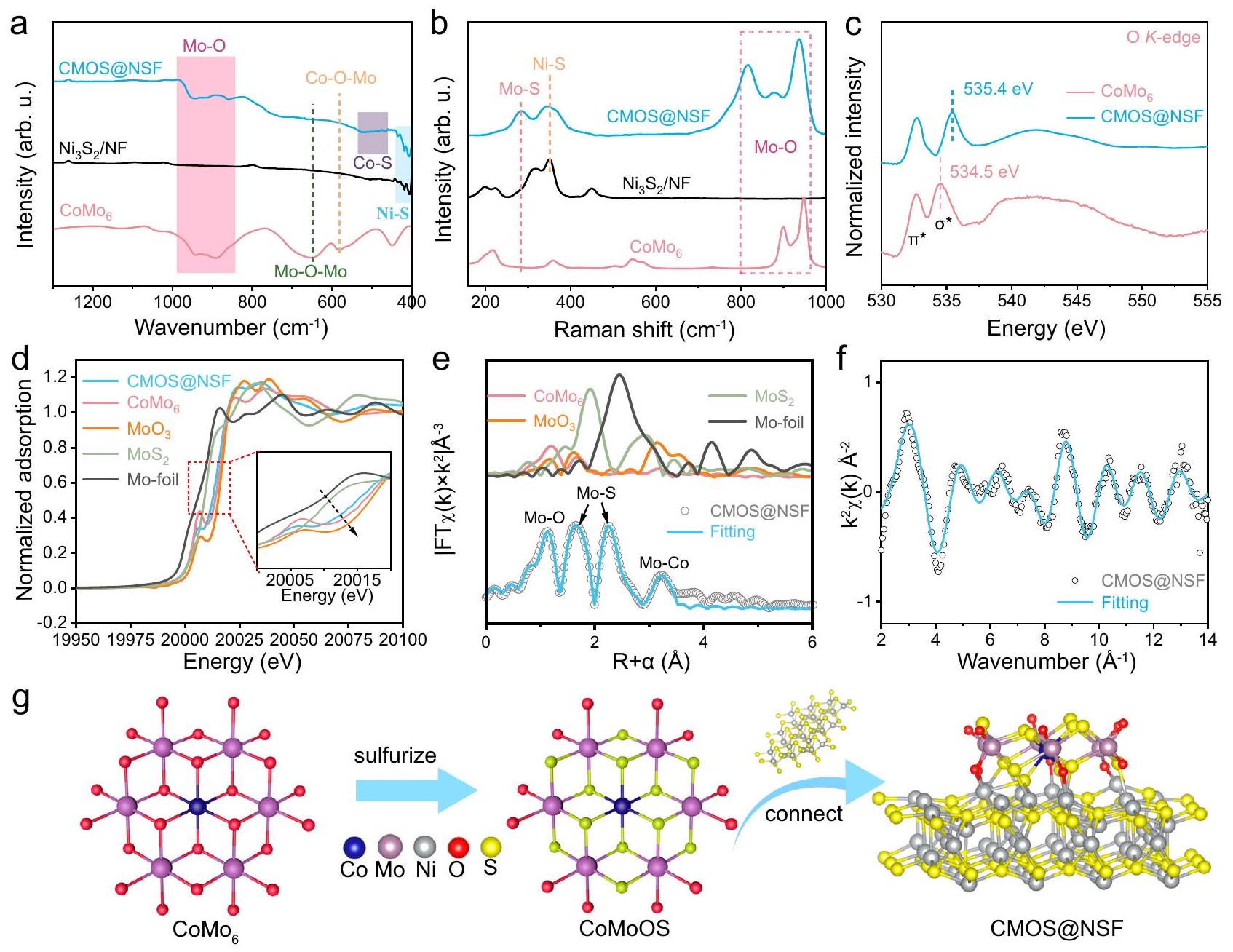
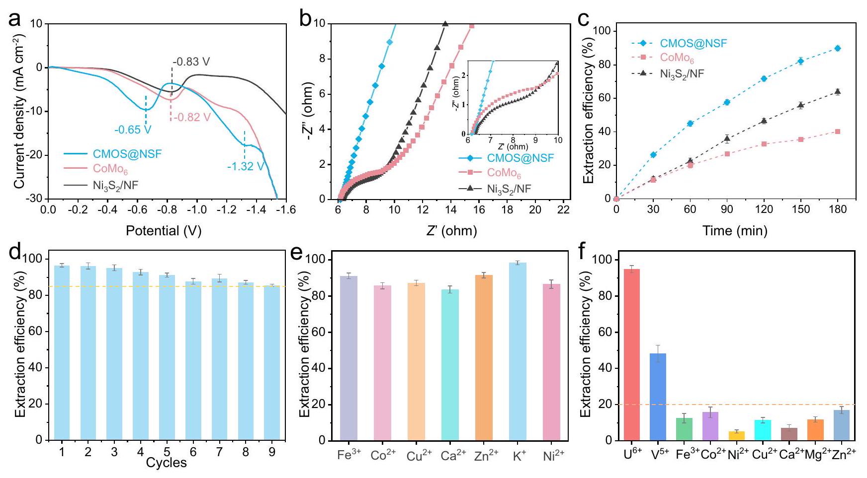
الشكل 2 | الترابط والبنية الإلكترونية لمواقع الواجهة. أ طيف FT-IR و ب طيف رامان لـ و . ج -طيف XANES عند الحافة و CMOS@NSF. د مو المعاير -طيف XANES. التوضيح هو عرض مكبر للمنطقة المحددة. هـ مقارنة بـ-بيانات الفضاء وخطوط الملاءمة الأفضل. ف المقابل-توافق الفضاء للمنحنيات لـ CMOS@NSF. آلية تشكيل COMS@NSF. تم توفير بيانات المصدر كملف بيانات المصدر. أظهرت قمم انخفاض ملحوظة، مما يدل على تقليل اليورانيوم (الشكل 3أ). بالإضافة إلى ذلك، أظهر CMOS@NSF إمكانات قمة انخفاض أكثر إيجابية.من و لـالاختزال. علاوة على ذلك، أظهر منحنى LSV لـ CMOS@NSF قمة اختزال جديدة عند -1.32 فولت، تتوافق مع اختزالإلىمما يدل على القدرة القوية للاختزال الكهروكيميائي لـ CMOS@NSF تجاه U(VI).
بعد ذلك، تم استخدام مطيافية impedancia الكهروكيميائية (EIS) للتحقيق في حركيات نقل الشحنة للمواد، حيث تعرض الشكل 3b مخططات نايكويست لجميع العينات. كان قطر نصف الدائرة في منطقة التردد العالي لـ CMOS@NSF أصغر من تلك الخاصة بـ و . في الوقت نفسه، كانت الميل في منطقة الترددات المنخفضة لـ CMOS@NSF تقريبًا مساوية لتلك لـوأعلى من ذلك لـمما يدل على انخفاض مقاومة النقل الإلكتروني وزيادة كفاءة انتشار الأيونات في CMOS@NSFالشكل التوضيحي الإضافي 7ب يظهر منحنيات الفولتمترية الدورية (CV) لـ CMOS@NSF، و بمعدل مسحفيحل في وجودالمنحنى لـ CMOS@NSF لديه أكبر مساحة محاطة، مما يدل على أعلى سعة نوعية.. بالإضافة إلى ذلك، مقارنةً بمنحنى CV في الحالة الخالية من اليورانيومالحل، الذي لم يظهر أي انخفاض كبير في القمم، أظهر منحنى CV بعد إضافة اليورانيوم قمة انخفاض ملحوظة عند -0.55 فولت، مما يوفر دليلاً إضافياً أظهر عملية تقليل اليورانيوم على CMOS@NSF. (الشكل التوضيحي 7c والشكل التوضيحي 7d).
من منظور الطاقة والاقتصاد، اختبرنا كفاءة استخراج اليورانيوم من المواد الثلاثة عند إمكانيات مختلفة في مياه البحر الملوثة بـاليورانيوم لاختيار إمكانيات استخراج اليورانيوم المناسبة. كما هو موضح في الشكل التكميلي 8a، زادت كفاءة استخراج اليورانيوم عمومًا مع زيادة الجهد. علاوة على ذلك، عند تطبيق جهد أعلى من -0.5 فولت، كانت كفاءة استخراج اليورانيوم لـ CMOS@NSF أعلى من تلك الخاصة بالمادتين الأخريين، وازداد هذا الفرق تدريجيًا مع زيادة الجهد. عندما تجاوز الجهد المطبق -1.4 فولت، لم يكن هناك زيادة ملحوظة في كفاءة الاستخراج. نظرًا للتركيز المنخفض للغاية لليورانيوم في مياه البحر والجهد الزائد الأنودي لأكسدة الماء، استخدمنا جهدًا صغيرًا قدره -1.4 فولت لاختبار أداء المادة خلال عملية الاستخراج الكهروكيميائي لليورانيوم. الشكل 3c يظهر التغيرات في معدلات استخراج اليورانيوم لـ CMOS@NSF. و مع مرور الوقت في مياه البحر المملوءة بـاليورانيوم. بعد 180 دقيقة من استخراج اليورانيوم الكهربائي، حقق CMOS@NSF كفاءة استخراج U(VI) من (دون ملاحظة تشبع)، والتي كانت أعلى بشكل ملحوظ من تلك الخاصة بـ و . علاوة على ذلك، قمنا بتقييم أداء استخراج اليورانيوم من المادة في مياه البحر الملوثة بـ 50 ويورانيوم
الشكل 3 | استخراج اليورانيوم الكهروكيميائي من مواقع الواجهة. أ منحنيات LSV لـ CMOS@NSF، و أقطاب كهربائية فيمعاليورانيوم، بمعدل مسحفي النطاق المحتمل من 0 إلىكلوريد الفضة (AgCl).منحنيات نايكويست للعينات فيحل في نطاق تردد من 0.1 هرتز إلى 100 كيلوهرتز. التوضيح هو عرض مكبر للمنطقة المحددة. ج العلاقة بين وقت استخراج اليورانيوم الكهروكيميائي وكفاءة الاستخراج (مياه البحر الملوثة بـاليورانيوم). د قابلية إعادة استخدام CMOS@NSF في مياه البحر الملوثة بـاليورانيوم. استخراج اليورانيوم في وجود أيونات متداخلة مختلفة (تركيز الأيونات المتنافسة: اختبار اختيار الأيون المتعايش (كانت تركيزات كل أيون) ). تمثل أشرطة الخطأ الانحراف المعياري لثلاث قياسات. في (د) تمثل الخط المنقط الخط الأفقي لـ كفاءة استخراج اليورانيوم. في (f) يمثل الخط المنقط الخط الأفقي لكفاءة استخراج تبلغ 20% لكل أيون. تم توفير بيانات المصدر كملف بيانات مصدر. (الشكل التوضيحي التكميلي 8b و 8c). أظهرت النتائج أن CMOS@NSF أظهر أداءً متفوقًا حتى عند تركيزات يورانيوم أعلى. علاوة على ذلك، قمنا باختبار كفاءة الاستخراج وحساب السعة القصوى للاستخراج لـ CMOS@NSF إلى U(VI) ضمن نطاق التركيز الابتدائي من 8 إلى. على الرغم من التركيز العالي لـ، ظلت كفاءة استخراج اليورانيوم بواسطة CMOS@NSF فوق، وأظهرت السعة القصوى للاستخراج اتجاهًا تصاعديًا خطيًا مع سعة استخراج غير مشبعة من (الشكل التوضيحي التكميلي 8d). نظرًا لأن عملية الامتزاز هي خطوة حاسمة في الاستخراج الكهربائي لليورانيوم، قمنا باختبار منحنيات الامتزاز لليورانيوم بواسطة المواد الثلاثة دون جهد. كما هو موضح في الشكل التوضيحي التكميلي 8e، لديه قدرة أقوى على امتصاص اليورانيوم، تليه CMOS@NSF، و. وقد تم نسب ذلك إلى المواقع الغنية بتنسيق الأكسجين علىو CMOS@NSF.
تمت دراسة إمكانية إعادة استخدام CMOS@NSF في مياه البحر الملوثة بـاليورانيوم (الشكل 3د). بعد 9 دورات من الإزالة وإعادة استخدام نفس القطب،كفاءة استخراج CMOS@NSF ظلت فوقأعلى من ذلك من و “، مما يشير إلى استقرار أفضل في دورة CMOS@NSF (الشكل التكميلي 8f). بالنظر إلى تداخل الكاتيونات في مياه البحر، قد تتنافس الكاتيونات التي تتراكم عند الكاثود خلال الاستخراج الكهروكيميائي لليورانيوم معلمواقع التنسيق. وبالتالي، فإن انتقائية المادة تجاهتمت دراسته لأول مرة باستخدام محلول نترات اليورانيوم ( ) مع إضافة كاتيونات تداخل فردية ( كما هو موضح في الشكل 3e، ظلت كفاءة استخراج CMOS@NSF لـ U(VI) فوقفي وجود كاتيونات متداخلة مفردة. بالإضافة إلى ذلك، اختبرنا كفاءة استخراج اليورانيوم من CMOS@NSF في وجود عدة أنيونات بحرية شائعة. أظهرت النتائج أن CMOS@NSF أظهر قدرة عالية على مقاومة التداخل مع الأنيونات (الشكل التوضيحي التكميلي 9a).
بعد ذلك، قمنا بتحضير محلول يحتوي على عدة أيونات ( ) واختبرت كفاءة استخراج كل أيون بعد الاستخراج الكهروكيميائي لليورانيوم. كما هو موضح في الشكل 3f، باستثناء الذي أظهر أعلى تأثير تنافسي علىكفاءة الاستخراج من )، كانت كفاءات الاستخراج لجميع الأيونات أقل من وكفاءة الاستخراج لـظل حول. علاوة على ذلك، قمنا باختبار تأثير الرقم الهيدروجيني على كفاءة استخراج اليورانيوم من CMOS@NSF في محلول اليورانيوم في نطاق pH من 4 إلى 10. أظهرت CMOS@NSF كفاءات استخراج اليورانيوم تتجاوزعبر نطاق pH الواسع بالكامل (الشكل التوضيحي 9b). أظهرت هذه النتائج أن CMOS@NSF تمتلك انتقائية جيدة لـالأيونات والاستقرار ضد الاضطرابات البيئية.
تحليل منتجات استخراج اليورانيوم الكهروتحفيزي
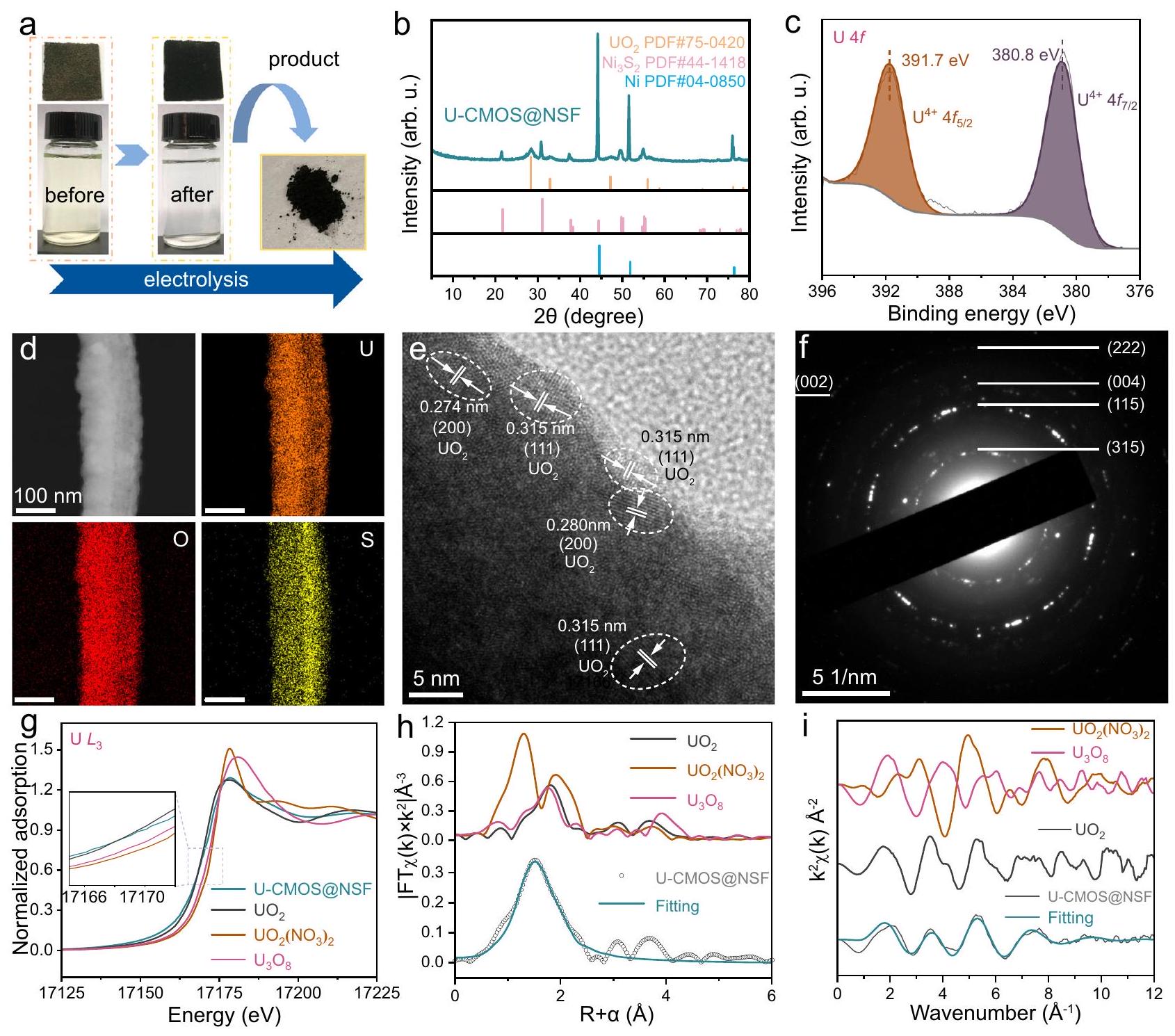
لتحليل منتجات الاستخراج الكهروكيميائي لليورانيوم، تم إجراء تجارب في مياه البحر الملوثة بـاليورانيوم. الشكل 4أ يظهر صور قطب CMOS@NSF والإلكتروليت قبل وبعد التفاعل. بعد 6 ساعات من المعالجة الكهروكيميائية، أصبح الإلكتروليت واضحًا بشكل ملحوظ وتم ترسيب كمية كبيرة من المادة السوداء على الأقطاب. تم جمع الرواسب السوداء على الأقطاب باستخدام الاستخراج بالموجات فوق الصوتية. الشكل 4ب والشكل التكميلي 10 يظهران أنماط XRD لمادة القطب والمنتج الأسود من اليورانيوم الذي تم جمعه بعد التفاعل، على التوالي. تم نسب قمم جديدة إلى (PDF#75-0420) لوحظت في المادة بعد التفاعل. بالإضافة إلى ذلك، القمم المعينة لـ ولم يتغير النيكل في مادة ما قبل التفاعل بشكل ملحوظ، مما يشير إلى أن المادة نفسها لم تتعرض لتغيير كبير أثناء إزالة اليورانيوم. وقد تم تأكيد هذه الملاحظة بشكل أكبر من خلال نتائج XPS لمادة ما بعد التفاعل، كما هو موضح في الشكل التكميلي 11a-e، دون تغييرات ملحوظة.
الشكل 4 | تحليل تمييز اليورانيوم. أ صور للأقطاب الكهربائية والمحاليل قبل وبعد التفاعل، بالإضافة إلى المنتجات المجمعة. قطب CMOS@NSF هو، وتم أخذ محلول 20 مل من الزجاجة من 100 مل من الإلكتروليت قبل وبعد التفاعل. ب نمط XRD، ج Uطيف، خرائط EDS، صورة HRTEM ونمط SAED لـ CMOS@NSF بعد استخراج اليورانيوم الكهربائي الكيميائي. الـ -طيف XANES عند الحافة للمنتج الأسود. الإطار: منطقة XANES قبل الحافة مكبرة. ح مقارنة-بيانات الفضاء وخطوط الملاءمة للمنتجات. i المقابل-تعديل منحنيات الفضاء للمنتجات. تم توفير بيانات المصدر كملف بيانات المصدر. تمت ملاحظته في الأطياف. كما كشف طيف المسح XPS عن قمم جديدة تتعلق باليورانيوم في نطاق طاقة الربط من (الشكل التوضيحي 11f). تم تحليل حالة التكافؤ لليورانيوم باستخدام الطيف. كما هو موضح في الشكل 4c، فإن فك التداخل لـقمة الطيف أعطت قمم مزدوجة عند و الذي يتوافق مع حالة U(IV). أظهرت نتائج EDS (الشكل 4d والشكل التكميلي 12) أن اليورانيوم كان موزعًا بشكل موحد وكثيف على القضبان النانوية، وأكد التوزيع المتجانس للعناصر الأخرى استقرار المادة. بالإضافة إلى ذلك، زادت نسبة عناصر الأكسجين إلى الكبريت في CMOS@NSF بعد التفاعل الكهروكيميائي بشكل ملحوظ مقارنة بما كانت عليه قبل عملية استخراج اليورانيوم الكهروكيميائية، مما يشير إلى أن اليورانيوم والأكسجين تم ترسيبهما معًا على سطح CMOS@NSF (الجدول التكميلي 3). علاوة على ذلك، كشفت صورة HRTEM في الشكل 4e عن حواف شبكية مميزة تت correspond إلى الطائرات (111) و(200). وبالمثل، فإن الطائرات (002) و(222) و(004) و(115) و(315) للتشتت منتمت ملاحظتها في نمط SAED للمادة (الشكل 4f).
لتأكيد أن المنتج الأسود هوقمنا بتحليله باستخدام مطيافية امتصاص إشعاع السنكروترون.طيف XANES عند حافة الامتصاص (الشكل 4 ج) أظهر أن حافة امتصاص منتج UCMOS@NSF تختلف بشكل كبير عن تلك الخاصة بـ و وكان قريبًا جدًا من حافة الامتصاص لـ. هذا يشير إلى أن حالة الأكسدة لليورانيوم كانت الشكل 4 هـ و و يوضح التحويل فورييه-طيف EXAFS الموزون والطيف الملائم للمنتج، على التوالي. تتطابق منحنى الملاءمة للمنتج الذي تم تصنيعه كهربائياً U-CMOS@NSF بشكل جيد مع-فضاء و-منحنيات بيانات الفضاء القياسية. في الـالتنسيق، مسافة U-Oنُسب ذلك إلى التنسيق بين ذرات الأكسجين الطرفية واليورانيوم. كان عدد التنسيق 2.7، الذي كان قريبًا من 3، يوفر دليلًا على مشاركة ثلاث ذرات أكسجين طرفية في التنسيق مع اليورانيوم، مما يؤكد دورها الهام في عملية تنسيق اليورانيوم (الجدول التكميلي 2). بالإضافة إلى ذلك، كانت مسافة U-O تزامن مع المسافة القياسية U-O في UO. هذه النتائج أكدت أن تم التنسيق على التآزر
الشكل 5 | تجربة مياه البحر الطبيعية لمواقع الواجهة. أ جهاز ذاتي التجميع لاستخراج اليورانيوم الكهربائي من مياه البحر. ب التركيب العنصري للمحلول الناتج من صفائح الأقطاب بعد استخراج اليورانيوم الكهربائي من مياه البحر الطبيعية. ج أداء استخراج اليورانيوم لـ CMOS@NSF والمواد المبلغ عنها سابقًا (انظر الجدول التكميلي 6). المحور الأيسر يتوافق مع تمثل كفاءة الاستخراج التي تظهرها مخطط الأعمدة، نسبة قدرة الاستخراج إلى الوقت. المحور الأيمن يتوافق مع كفاءة الاستخراج التي تمثلها مخطط الخط المنقط، والذي يظهر معدل الاستخراج مع مرور الوقت. يتم استخدام رمز الثماني الأضلاع لتسليط الضوء على “هذا العمل”. تم توفير بيانات المصدر كملف بيانات المصدر. واجهة تقليل التنسيق وتم تقليلها إلى. بالمقارنة مع المنتجات المبلغ عنها في السنوات الأخيرة، الـتم تقدير المنتج في هذا العمل بشكل خاص بسبب غياب المعادن القلوية والنسبة المئوية النظرية العالية لوزن اليورانيوم (الجدول التكميلي 4).
تجربة مياه البحر الطبيعية
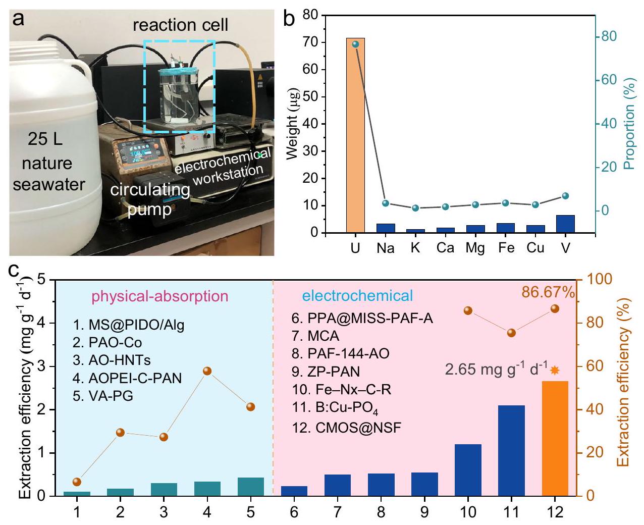
للتحقق من الأداء العملي لـ CMOS@NSF في مياه البحر الطبيعية، قمنا بتجميع جهاز بسيط لاستخراج اليورانيوم كهربائياً من مياه البحر تحت ظروف المختبر الحالية. كما هو موضح في الشكل 5a، استخدم الجهاز مضخة دوران لنقل مياه البحر الطبيعية من حاوية سعة 25 لتر إلى خلية التفاعل الكهربائي. بعد استخراج اليورانيوم كهربائياً في خلية التفاعل، تم إرجاع مياه البحر إلى الحاوية. تتدفق مياه البحر عبر خلية التفاعل بمعدل ثابت، مما يحافظ على عملية استخراج كهربائية ديناميكية. في الوقت نفسه، لتعزيز تأثير استخراج اليورانيوم، قمنا بتكبير المادة إلى حجم، مع مبلغ تحميل قدره . بعد 24 ساعة من الاستخراج الكهروكيميائي لليورانيوم باستخدام هذا الإعداد البسيط، قمنا بغسل مادة القطب بحل HCl وحددنا محتويات اليورانيوم وعناصر أخرى في المحلول الناتج. من بين العناصر المستخرجة من الأقطاب، كان اليورانيوم يشكلبالكتلة، بينما كان محتوى العناصر الأخرى منخفضًا نسبيًا (الشكل 5ب والجدول التكميلي 5). كانت الكمية الإجمالية من اليورانيوم المستخرج من مادة القطب الكهربائي هي، مع كفاءة استخراج تبلغكانت القدرة المحسوبة على الاستخراج، التي تتجاوز تلك الخاصة بمعظم المواد الماصة لاستخراج اليورانيوم من مياه البحر والمواد الكهروتحفيزية المبلغ عنها (الشكل 5c).
آلية التفاعل
القدرة على تقليل وإيداع بشكل فعالأيونات كشوائب منخفضةعلى CMOS@NSF يحفزنا لاستكشاف آلية التفاعل الأساسية. بالنظر إلى أن الامتزاز لـالأيونات على سطح المادة هي واحدة من العمليات الرئيسية في استخراج اليورانيوم، قمنا أولاً بإنشاء نموذج هيكلي مطابق ومحاكاة امتصاصالأيونات على واجهة التنسيق-الاختزال التآزري لـ CMOS@NSF. في الوقت نفسه، قمنا بإنشاء نماذج الامتزاز لـالأيونات على الكبريت بالكاملعلى (110) (CMS@NSF)، CoMoOS و (110) على التوالي. كما هو موضح في الشكل 6a، فإن طاقة الامتزاز لـعلى CMOS@NSF ( -4.07 eV ) كان أعلى قليلاً من ذلك على، ولكن أقل بكثير من ذلك على و CMS@NSF ( -2.03 eV ). أظهرت هذه النتائج أن الأكسجين الطرفي يلعب دورًا مهمًا في “التقاط” . علاوة على ذلك، بعد امتصاص في النماذج الأربعة أعلاه، زاوية الرابطة لـاتبعت الأمر: (CoMoOS) (الجدول التكميلي 7). كشفت هذه النتيجة أن سهلت تقليل المنسقمن خلال تحليل الفروق في توزيع الشحنة بعد الامتزاز لـعلى هياكل مختلفة، نستكشف بشكل أعمق آليات الاختزال والترسيب لـعلى المواد. كما هو موضح في الشكل 6ب، حدث تراكم كبير للإلكترونات على ذرات الأكسجين الطرفية في CoMoOS وذرات النيكل في، مصحوبًا بفقدان الإلكترونات على السطح الممتصالأيونات. بالمقارنة مع هيكل CMS@NSF وهيكل CoMoOS، أظهر هيكل CMOS@NSF قدرة نقل شحنة أكثر وضوحًا. علاوة على ذلك، كشفت تحليل الكثافة الجزئية للحالات (PDOS)، كما هو موضح في الشكل 6c، عن وجود المزيد من حالات النيكل (5d) غير المشغولة فوق مستوى فيرمي، بينما المزيد من
الشكل 6 | آلية التفاعل لمواقع الواجهة. أ تكوينات الامتزاز المحسّنة لـعلى CMOS@NSF، CMS@NSF، CoMoOS و (110). ب مخططات فرق كثافة الشحنة على CMS@NSF وCMOS@NSF. تمثل الألوان الصفراء والسماوية مناطق إثراء الشحنة ونقصها، على التوالي. ج PDOS للنيكل بعد امتصاص الهيدروجين. مستوى فيرمي ينتقل إلى الصفر.آلية تخطيطية لاستخراج اليورانيوم الكهربائي من مياه البحر باستخدام CMOS@NSF مع واجهة تنسيق-اختزال تآزرية. تمثل المناطق المحاطة بالخطوط البيضاوية في (أ، د) تُقدم بيانات المصدر كملف بيانات مصدر. محتلتمت ملاحظة حالات تحت مستوى فيرمي. كانت هذه النتيجة متوافقة مع نقل الشحنة التفاضلي المحسوب من ذرات النيكل إلى ذرات الأكسجين من.
استنادًا إلى التحليل أعلاه، قامت CMOS@NSF بتقليل بشكل فعال ومستقرفي مياه البحر ذات الشوائب المنخفضة، المنسوبة إلى واجهة التنسيق-الاختزال التآزري. الشكل 6d يظهر مخططات موقع واجهة التنسيق-الاختزال التآزري والموقع التقليدي للتنسيق في استخراج اليورانيوم الكهروكيميائي. بالمقارنة مع الموقع التقليدي للتنسيق، من ناحية، كانت جيوب الأكسجين الطرفية لـ CMOS@NSF تعمل كمواقع تنسيق قوية لـالربط. من ناحية أخرى، فإن ذرات النيكل في واجهة التنسيق-الاختزال التآزري مرتبطة كيميائيًا بالأكسجين المحوري فيوعملت كقناة نقل إلكترونات مباشرة لتعزيز اختزال اليورانيوم. وبالتالي،تم تقليلها بكفاءة إلى U(IV) عند واجهة تقليل التنسيق التآزري، مما تجنب أكسدة U(IV) والترسيب المشترك للمعادن القلوية.
نقاش
باختصار، أبلغنا عن واجهة تنسيق-اختزال تآزرية نجحت في استخراج الشوائب المنخفضة.المواد الصلبة من مياه البحر. تم إنشاء واجهة التنسيق-الاختزال المتصلة بشكل كبير من خلال النمو في الموقع للبوليوكسوميتالات الكبريتية-علىلقد أظهرت التوصيف الشامل وحسابات DFT أن جيوب الأكسجين الطرفية في هيكل CoMoOS ضمن هذه الواجهة تتمتع بقدرات قوية على الالتقاط لـ. بالإضافة إلى ذلك، الاتصال الوجهي لـ CMOS مع، حيث ارتبط النيكل كيميائيًا بالأكسجين المحوري فيسرّعت نقل الإلكترون وعزّزت الاختزال لـإلى الأسودمنتجات صلبة ذات شوائب منخفضة من مياه البحر. في تجربة مياه البحر الطبيعية، CMOS@NSF حقق كفاءة استخراج ملحوظة منفي 24 ساعة، مع قدرة استخراج تبلغفي جهاز تم تجميعه ذاتيًا لاستخراج اليورانيوم الكهربائي من مياه البحر. لا يقدم هذا العمل مادة لاستخراج اليورانيوم الكهربائي فحسب، بل يوفر أيضًا استراتيجية فعالة لاستخراج اليورانيوم الكهربائي من مياه البحر مع شوائب منخفضة.
طرق
المواد الكيميائية والمواد
نترات اليورانيومنترات الأمونيوم رباعي الهيدراتوسلفات الكوبالت (II) هيدرات سباعيةتم شراؤها من شركة علاء الدين الصناعية المحدودة. بيروكسيد الهيدروجين (تم شراء (ثيو يوريا) من شركة تشنغدو كولون للمواد الكيميائية المحدودة.وسلفات الصوديوم اللامائيةتم شراؤها من شركة شنغهاي ماكلين للصناعات الكيميائية الحيوية المحدودة. محلول غشاء نافيون (NR50،تم الاستحواذ عليه من شركة شانغهاي ماكلين للكيماويات الحيوية المحدودة.
تركيب المواد
تركيبأولاً، تم إذابة رباعي هيدرات أمونيوم الموليبداتفي الماء المغلي. ثم، صب محلولاً يحتوي على كبريتات الكوبالت (II) هيدرات سباعية ، 15 ملليمول) إلى المحلول المغلي. بعد ذلك، أضيفتمع التحريك، وغليت لمدة 30 دقيقة. بعد ذلك، تم تبريد الخليط في الثلاجة للسماح بالتبلور. تم إعادة تبلور البلورات الناتجة مرتين في الماء للحصول على نقاء نسبي..
تركيب CMOS@NSF. تركيب CMOS@NSF باستخدام طريقة هيدروحرارية بسيطة من خطوة واحدة. باختصار، أضيفت0.05 مللي مول) الناتج من العملية السابقة في الماء منزوع الأيونات. ثم أضيفت الثيويورياوتم التحريك لمدة
15 دقيقة. بعد ذلك، تم وضع NF ( )، الذي تم معالجته بحمض الهيدروكلوريك، مع المحلول أعلاه في أوتوكلاف من الفولاذ المقاوم للصدأ سعة 50 مل مبطن بالبوليترافلورإيثيلين (PTFE). تم إجراء تفاعل هيدروحراري عند لمدة 8 ساعات. أخيرًا، تم شطف المادة الناتجة بالماء المنزوع الأيونات والإيثانول، ثم تم تجفيفها. لتخليق مواد بنسب مختلفة من S:Mo، تم تعديل كمية الثيويوريا المضافة.
تركيب. باستخدام نفس الطريقة الموضحة لتخليق CMOS@NSF، ولكن دون إضافة.
توصيفات
تم تسجيل أنماط حيود الأشعة السينية (XRD) للعينات بواسطة جهاز حيود الأشعة السينية PANalytical Empyrean عند 40 كيلوفولت و40 مللي أمبير معإشعاعتم إجراء صور SEM بواسطة مجهر إلكتروني مسح ميداني من نوع ZEISS Sigma 300. تم جمع صور TEM و HRTEM باستخدام مجهر إلكتروني نافذ من نوع FEI Teccnai G2 F20 مع مطياف طيفي للطاقة المشتتة من نوع FEI 2 SDD. تم تسجيل طيف XPS باستخدام مطياف إلكتروني من نوع Thermo Scientific ESCALAB Xi+ مع مصدر ضوء أحادي اللون.-مصدر أشعة. تم تسجيل طيف EPR باستخدام جهاز Bruker A300-10/12 من ألمانيا. تم إجراء قياسات FT-IR على جهاز مطياف الأشعة تحت الحمراء بتحويل فورييه PerkinElmer Spectrum One في قرص مضغوط من KBr. تم استخدام تقنية XAFS لتوصيف حالات الأكسدة للعينات من خلال وضع النقل للأكسجين.-الحافة، مو-الحافة و U-حافة الامتصاص في مختبر الإشعاع السنكروتروني الوطني (NSNR). تم معايرة مواقع حواف الامتصاص خلال قياسات XAFS. تم جمع بيانات EXAFS من وحدة ATHENA، المدمجة ضمن مجموعة برامج IFEFIT. تم تسجيل طيف رامان باستخدام جهاز Renishaw InVia. تم استخدام مطياف انبعاث البلازما المقترنة بالحث (ICP، Agilent، الولايات المتحدة) لتسجيل تركيزات الأيونات.
الحسابات النظرية
تمت إجراء الحسابات ضمن إطار نظرية الكثافة الوظيفية (DFT) المدمجة في حزمة المحاكاة الأولية فيينا (VASP6.3.2)تم وصف التفاعل بين الأيونات والإلكترونات في طريقة الموجة المعززة بالمش projector Augmented Wave (PAW).تم وصف طاقة تبادل الإلكترونات والتداخل باستخدام دالة بيردو-بورك-إيرزينهورف (PBE) المعتمدة على التقريب العام للتدرج.تم إجراء تصحيحات التشتت شبه التجريبية في لندن من قبل غريمي وزملائه (DFT-D3) لحساب التفاعلات بين الممتصات والألواح.تم تطبيق تصحيح هوبارد-يو لوصف أفضل للإلكترونات d المحلية لليورانيوم. كانت قيم الـمعلمات U و Co و Ni و Mo تم تعيينها إلى، و 2.3 على التوالينماذج الهيكل السطحي لـتم بناؤه. فقط الطبقات الثلاث العليا من الذرات تم استرخاؤها في الحساب. منطقة فراغ كبيرة بما فيه الكفاية منتم استخدامه لجميع النماذج لضمان فصل الصور الدورية بشكل جيد. تم إجراء تكاملات منطقة بريل باستخدام شبكات نقاط خاصة من MonkhorstPack. تمركزت النقاط حول غاما (تم استخدام شبكة نقاط k للنماذج. للحصول على الهيكل الدقيق، تم ضبط طاقة قطع الموجة المسطحة على 500 إلكترون فولت. تم ضبط تقارب القوة ليكون، وتم تحديد تقارب الطاقة الكلي ليكون.
الاختبار الكهروكيميائي
تم إجراء جميع الاختبارات الكهروكيميائية باستخدام محطة العمل الكهروكيميائية CHI660E. الإجراءات كما يلي. CMOS@NSF أو تم استخدام القطعة مباشرة كإلكترود عمل.تم وزن المسحوق، وتفريقه في 2 مل من الإيثانول معمحلول نافيون، وتم معالجته بالموجات فوق الصوتية لمدة 0.5 ساعة للحصول على محلول حبر تحفيزي. ثم تم فرش محلول الحبر علىألياف الكربون (CF) كقطب العمل. تم استخدام نظام ثلاثي الأقطاب للاختبار، مع المواد المحضرة كقطب العمل، والقطب الكهربائي كـ إلكترود مرجعي، وإلكترود سلك بلاتيني كإلكترود مضاد. تم إجراء اختبارات LSV فيحل في وجود أو غياببمعدل مسحفي النطاق المحتمل من 0 إلى -1.6 فولت (مقابلتم إجراء اختبارات السيرة الذاتية فيحل في وجود أو غياب، بمعدلات مسح مختلفة (، و ) في النطاق المحتمل من 0.2 إلى -1.2 فولت (مقابل تم إجراء اختبار EIS فيحل في نطاق تردد من 0.1 هرتز إلى 100 كيلوهرتز.
استخراج اليورانيوم الكهربائي من تجارب مياه البحر الملوثة باليورانيوم
تم إجراء تجارب استخراج اليورانيوم من مياه البحر الملوثة باليورانيوم باستخدام نظام ثلاثي الأقطاب. تم تحضير مواد أقطاب مختلفة باستخدام المواد المذكورة أعلاه للقطب العامل. سلك من البلاتين (Pt) وتم استخدام الأقطاب الكهربائية كقطب مضاد وقطب مرجعي، على التوالي. تم إجراء استخراج اليورانيوم تحت جهد ثابت قدره -1.4 فولت. تم دراسة تأثيرات تركيزات اليورانيوم الأولية المختلفة (8، 50، و ) وتم قياس تأثير الأيونات المتداخلة المختلفة على أداء استخراج اليورانيوم الكهروكيميائي. تم تحديد تركيزات اليورانيوم وأيونات الكاتيونات الأخرى في المحلول الكهربائي بعد الاستخراج الكهروكيميائي باستخدام ICP. خلال عملية الإزالة، تم تحليل القطب العامل المحمّل باليورانيوم لمدة 10 دقائق عند جهد عكسي قدره 1.4 فولت في تم إجراء تجارب الاستخراج ثلاث مرات، وتم تضمين أشرطة الخطأ في المنحنيات.
تجارب الامتزاز الفيزيائي لليورانيوم
تجارب الامتزاز الفيزيائي لـ، و تم إجراء التجارب على اليورانيوم دون تطبيق جهد خارجي. تم وضع كل من المواد الثلاث في 100 مل من محلول مياه البحر المضاف إليهاليورانيوم بسرعة مثيرة.
تجارب الاستخراج الكهروكيميائي لليورانيوم في مياه البحر الطبيعية
تم إجراء تجربة الاستخراج الكهروكيميائي لليورانيوم من مياه البحر الطبيعية أيضًا باستخدام نظام ثلاثي الأقطاب. تم تحضير القطب العامل باستخدام نفس الطريقة الموضحة لـ CMOS@NSF، مع تعديل متناسب لـ. كانت القطب المرجعي والقطب المضاد كما هو موصوف أعلاه. تم إجراء التجربة على جهاز بسيط تم تجميعه ذاتيًا لاستخراج اليورانيوم باستخدام 25 لترًا من مياه البحر الحقيقية. قبل استخراج اليورانيوم، تم تصفية مياه البحر عبر عملية تصفية فراغية. تم التحكم في معدل تدفق دوران مياه البحر عندبعد 24 ساعة من استخراج اليورانيوم كهربائياً، تم إزالة مادة القطب، ثم تم شطفها أولاً بالماء النقي، ثم نقعها في 0.5 م HCl لإزالة اليورانيوم المستخرج. بعد ذلك، تم تحضير المحلول في محلول مركز بتركيز 10 مل. تم قياس محتوى اليورانيوم في محلول الإزالة بواسطة ICP، وتم حساب سعة الاستخراج.
أين و تمثل تركيز اليورانيوم الابتدائي والنهائي، على التوالي.
أين و تمثل كتلة اليورانيوم المستخرج من القطب وكتلة مادة القطب، على التوالي؛تمثل وقت استخراج اليورانيوم الكهروكيميائي.
أين، و هي الطاقات الكلية للمواد الممتصة-الركيزة (AS)، والركيزة (S)، والمواد الممتصة (A)، على التوالي.
توفر البيانات
البيانات التي تدعم نتائج الدراسة مدرجة في النص الرئيسي وملفات المعلومات التكميلية. تم توفير بيانات المصدر مع هذه الورقة. تتوفر ملفات بيانات المصدر في Figshare تحت رمز الوصولhttps://doi.org/10.6084/m9.figshare.28142705.
References
Mei, D., Liu, L. & Yan, B. Adsorption of uranium (VI) by metal-organic frameworks and covalent-organic frameworks from water. Coord. Chem. Rev. 475, 214917 (2023).
Hu, Y. et al. Photochemically triggered self-extraction of uranium from aqueous solution under ambient conditions. Appl. Catal. B Environ. 322, 122092 (2023).
Abney, C. W., Mayes, R. T., Saito, T. & Dai, S. Materials for the recovery of uranium from seawater. Chem. Rev. 117, 13935-14013 (2017).
Xie, Y. et al. Uranium extraction from seawater: material design, emerging technologies and marine engineering. Chem. Soc. Rev. 52, 97-162 (2023).
Lin, L. et al. Electrocatalytic removal of low-concentration uranium using nanotube arrays/Ti mesh electrodes. Environ. Sci. Technol. 56, 13327-13337 (2022).
Liu, C. et al. A half-wave rectified alternating current electrochemical method for uranium extraction from seawater. Nat. Energy 2, 17007 (2017).
Chi, F., Zhang, S., Wen, J., Xiong, J. & Hu, S. Highly efficient recovery of uranium from seawater using an electrochemical approach. Ind. Eng. Chem. Res. 57, 8078-8084 (2018).
Liu, T. et al. Removal and recovery of uranium from groundwater using direct electrochemical reduction method: performance and implications. Environ. Sci. Technol. 53, 14612-14619 (2019).
Zhou, L. et al. Interface coupling induced built-in electric fields accelerate electro-assisted uranium extraction over nanosheet arrays. Appl. Catal. B Environ. 353, 124052 (2024).
Lin, T. et al. Ion pair sites for efficient electrochemical extraction of uranium in real nuclear wastewater. Nat. Commun. 15, 4149 (2024).
Yang, H. et al. Functionalized iron-nitrogen-carbon electrocatalyst provides a reversible electron transfer platform for efficient uranium extraction from seawater. Adv. Mater. 33, 2106621 (2021).
Yang, S. et al. Electro-adsorption and reduction of uranium(VI) by @COFs electrode with enhanced removal performance. Chem. Eng. J. 474, 145598 (2023).
Liu, X. et al. Highly efficient electrocatalytic uranium extraction from seawater over an amidoxime-functionalized In-N-C Catalyst. Adv. Sci. 9, 2201735 (2022).
Zhou, L. et al. Unveiling the critical role of surface hydroxyl groups for electro-assisted uranium extraction from wastewater. Inorg. Chem. 62, 21518-21527 (2023).
Liu, X. et al. Secondary metal ion-induced electrochemical reduction of U(VI) to U(IV) solids. Nat. Commun. 15, 7736 (2024).
Feng, J. X., Wu, J. Q., Tong, Y. X. & Li, G. R. Efficient hydrogen evolution on Cu nanodots-decorated nanotubes by optimizing atomic hydrogen adsorption and desorption. J. Am. Chem. Soc. 140, 610-617 (2018).
Du, H. et al. Mountain-shaped nickel nanostripes enabled by facet engineering of nickel foam: a new platform for high-current-density water splitting. Adv. Funct. Mater. 34, 2311854 (2024).
Zhai, P. et al. Engineering active sites on hierarchical transition bimetal oxides/sulfides heterostructure array enabling robust overall water splitting. Nat. Commun. 11, 5462 (2020).
Reddy, M. A., Ramulu, B. & Su, Y. J. Tri-metallic core-shell structures by confining crystalline nanorod and amorphous nanosheet architectures for high-performance hybrid supercapacitors. Chem. Eng. J. 451, 139018 (2023).
Nguyen, D. C. et al. Rh single atoms/clusters confined in metal sulfide/oxide nanotubes as advanced multifunctional catalysts for green and energy-saving hydrogen productions. Appl. Catal. B: Environ. 313, 121430 (2022).
Zhou, Z. et al. Intercalation-activated layered nanobelts as biodegradable nanozymes for tumor-specific photo-enhanced catalytic therapy. Angew. Chem. Int. Ed. 61, e202115939 (2022).
Weber, T., Muijsers, J. C., Wolput, J., Verhagen, C. & Niemantsverdriet, J. Basic reaction steps in the sulfidation of crystalline to , as studied by X-ray photoelectron and infrared emission spectroscopy. J. Phys. Chem. 100, 14144-14150 (1996).
Tran, P. D. et al. Coordination polymer structure and revisited hydrogen evolution catalytic mechanism for amorphous molybdenum sulfide. Nat. Mater. 15, 640-646 (2016).
Dai, J. et al. @polyaniline for aqueous ammonium-ion supercapacitors. Adv. Mater. 35, 2303732 (2023).
Ren, H. et al. Facile synthesis of free-standing nickel chalcogenide electrodes for overall water splitting. J. Energy. Chem. 26, 1217-1222 (2017).
Tang, X. et al. Sulfur edge in molybdenum disulfide nanosheets achieves efficient uranium binding and electrocatalytic extraction in seawater. Nanoscale 14, 6285-6290 (2022).
Shao, M. et al. High-performance biodegradable energy storage devices enabled by heterostructured composites. Small 19, 2205529 (2023).
Ma, H., Sun, C., Wang, Z. & Jiang, Q. Tuning the electronic structure of nanosheets through S doping for enhanced oxygen evolution. Nanoscale 13, 17022-17027 (2021).
Guo, Z. et al. Defect engineering associated with cationic vacancies for promoting electrocatalytic water splitting in iron-doped nanosheet arrays. J. Colloid. Interf. Sci. 654, 785-794 (2024).
Liu, X. et al. Tunable cationic vacancies of cobalt oxides for efficient electrocatalysis in batteries. Adv. Energy. Mater. 10, 2001415 (2020).
Yu, H. et al. Transition-metal-controlled inorganic ligand-supported non-precious metal catalysts for the aerobic oxidation of amines to imines. Chem-Eur. J. 23, 13883-13887 (2017).
Nomiya, K., Takahashi, T., Shirai, T. & Miwa, M. Anderson-type heteropolyanions of molybdenum(VI) and tungsten(VI). Polyhedron 6, 213-218 (1987).
Gao, Y., Wang, M. & Zhang, G. Effect of calcium ions on the surface properties of heterogenite and conducive to sulfidization flotation: Insight from oxygen vacancy. Appl. Surf. Sci. 640, 158328 (2023).
Huang, Y. et al. Atomically engineering activation sites onto metallic 1T-MoS catalysts for enhanced electrochemical hydrogen evolution. Nat. Commun. 10, 982 (2019).
Bradley, J. A. et al. Experimental and theoretical comparison of the O K-edge nonresonant inelastic X-ray scattering and X-ray absorption spectra of . J. Am. Chem. Soc. 132, 13914-13921 (2010).
Song, W. et al. Pseudocapacitive insertion in channels of -C nanofibers with high rate and ultrastable performance. ACS Appl. Mater. Interfaces 11, 17416-17424 (2019).
Sun, S. et al. Lattice pinning in via coherent interface with stabilized intercalation. Nat. Commun. 14, 6662 (2023).
Yu, Z. Y. et al. General synthesis of tube-like nanostructured perovskite oxides with tunable transition metal-oxygen covalency for efficient water electrooxidation in neutral media. J. Am. Chem. Soc. 144, 13163-13173 (2022).
Zhang, B. W. et al. Atomically dispersed dual-site cathode with a record high sulfur mass loading for high-performance room-temperature sodium-sulfur batteries. Adv. Mater. 35, 2206828 (2023).
Wu, H. C. et al. Antiferroelectric antiferromagnetic type-I multiferroic . Phys. Rev. B 100, 245119 (2019).
Huang, J., Liu, Z., Huang, D., Jin, T. & Qian, Y. Electrochemical deposition of uranium oxide with an electrocatalytically active electrode using double potential step technique. Chinese. Chem. Lett. 33, 3762-3766 (2022).
Hao, M. et al. Converging cooperative functions into the nanospace of covalent organic frameworks for efficient uranium extraction from seawater. CCS Chemistry 4, 2294-2307 (2022).
Zhu, Q. et al. A new view of supercapacitors: integrated supercapacitors. Adv. Energy. Mater. 9, 1901081 (2019).
Liao, Y. et al. Uranium capture by a layered 2D/2D niobium phosphate/holey graphene architecture via an electro-adsorption and electrocatalytic reduction coupling process. J. Hazard. Mater. 442, 130054 (2023).
Wu, X. et al. Sol-gel transition effect based on konjac glucomannan thermosensitive hydrogel for photo-assisted uranium extraction. Sci. Bull. 69, 3042-3054 (2024).
Blake, A. J. et al. A new home for studies of crystal growth and characterisation. Acta. Crystallogr. B 77, 456-457 (2021).
Dewey, C., Sokaras, D., Kroll, T., Bargar, J. R. & Fendorf, S. Calcium-uranyl-carbonato species kinetically limit U(VI) reduction by Fe(II) and lead to -bearing ferrihydrite. Environ. Sci. Technol. 54, 6021-6030 (2020).
Wei, H. et al. Iced photochemical reduction to synthesize atomically dispersed metals by suppressing nanocrystal growth. Nat. Commun. 8, 1490 (2017).
Kresse, G. & Furthmüller, J. Efficient iterative schemes for ab initio total-energy calculations using a plane-wave basis set. Phys. Rev. B 54, 11169-11186 (1996).
Blöchl, P. E. Projector augmented-wave method. Phys. Rev. B 50, 17953-17979 (1994).
Perdew, J. P., Burke, K. & Ernzerhof, M. Generalized gradient approximation made simple. Phys. Rev. Lett. 77, 3865-3868 (1996).
Grimme, S. Semiempirical GGA-type density functional constructed with a long-range dispersion correction. J. Comput. Chem. 27, 1787-1799 (2006).
Wiktor, J. et al. Coupled experimental and DFT + U investigation of positron lifetimes in . Phys. Rev. B 90, 184101 (2014).
شكر وتقدير
تم دعم هذا العمل من قبل NSFC (رقم U23A2O105 و U2267224، و. ز.)، برنامج العلوم والتكنولوجيا في سيتشوان (رقم 2024NSFTDOO12، و. ز. و 2025ZNSFSCO949، هـ. ل.)، صندوق الابتكار والتنمية لتحالف استخراج اليورانيوم من مياه البحر (و. ز.)، مشروع المختبر الوطني الرئيسي لمواد الطاقة الصديقة للبيئة في SWUST (رقم.
21fksy22، W.Z.) وصندوق البحث في SWUST لدرجة الدكتوراه (رقم 23zx7110، H.L.). يعبر المؤلفون عن امتنانهم لفريق الكيمياء النظرية والحسابية في مختبر Shiyanjia (www.shiyanjia.com) لمساعدتهم القيمة. بالإضافة إلى ذلك، يود المؤلفون أن يشكروا مختبر شياجيانجيا (www.shiyanjia.com) لتقديم الدعم القيم في تحليل SEM وTEM وXPS.
مساهمات المؤلفين
قدّم H.G. أهم المساهمات، على الرغم من أن جميع المؤلفين ساهموا في العمل. صمّم H.G. و R.H. و H.L. الدراسات وكتبوا الورقة. قام H.G. بإجراء معظم التجارب. قام E.H. و Y.W. و Z.O. و B.H. بإجراء جزء من التجارب. قدّم W.Z. المشورة والمواد. قام J.L. بإجراء حسابات DFT. أشرف H.L. و R.H. و W.Z. على البحث. ساهم جميع المؤلفين في تحليل البيانات وعلقوا على المخطوطة.
ملاحظة الناشر: تظل شركة سبرينغر ناتشر محايدة فيما يتعلق بالمطالبات القضائية في الخرائط المنشورة والانتماءات المؤسسية.
الوصول المفتوح هذه المقالة مرخصة بموجب رخصة المشاع الإبداعي النسب-غير التجارية-عدم الاشتقاق 4.0 الدولية، التي تسمح بأي استخدام غير تجاري، ومشاركة، وتوزيع، وإعادة إنتاج في أي وسيلة أو صيغة، طالما أنك تعطي الائتمان المناسب للمؤلفين الأصليين والمصدر، وتوفر رابطًا لرخصة المشاع الإبداعي، وتوضح إذا قمت بتعديل المادة المرخصة. ليس لديك إذن بموجب هذه الرخصة لمشاركة المواد المعدلة المشتقة من هذه المقالة أو أجزاء منها. الصور أو المواد الأخرى من طرف ثالث في هذه المقالة مشمولة في رخصة المشاع الإبداعي الخاصة بالمقالة، ما لم يُشار إلى خلاف ذلك في سطر الائتمان للمادة. إذا لم تكن المادة مشمولة في رخصة المشاع الإبداعي الخاصة بالمقالة وكان استخدامك المقصود غير مسموح به بموجب اللوائح القانونية أو يتجاوز الاستخدام المسموح به، فستحتاج إلى الحصول على إذن مباشرة من صاحب حقوق الطبع والنشر. لعرض نسخة من هذه الرخصة، قم بزيارة http:// creativecommons.org/licenses/by-nc-nd/4.0/. (ج) المؤلف(ون) 2025
المختبر الوطني الرئيسي لمواد الطاقة الصديقة للبيئة، كلية الدفاع الوطني وعلوم وتكنولوجيا النووية، كلية المواد والكيمياء، مركز الابتكار لتكنولوجيا السلامة النووية البيئية، جامعة جنوب غرب العلوم والتكنولوجيا، مينيانغ، جمهورية الصين الشعبية. كلية الكيمياء والهندسة الكيميائية، جامعة نانتشانغ، نانتشانغ، جمهورية الصين الشعبية. البريد الإلكتروني: Liuhuanhuan@swust.edu.cn; her@swust.edu.cn; zhuwenkun@swust.edu.cn
A synergistic coordination-reduction interface for electrochemical reductive extraction of uranium with low impurities from seawater
Received: 10 November 2024
Accepted: 12 February 2025
Published online: 27 February 2025
Check for updates
Hongliang Guo , Enmin Hu , Yihao Wang , Zhenhong Ou , Bichu Huang , Jia Lei , Huanhuan Liu →, Rong He & Wenkun Zhu ⊗
Electrochemical extraction of uranium from seawater is a promising strategy for the sustainable supply of nuclear fuel, whereas the current progress suffers from the co-deposition of impurities. Herein, we construct a synergistic coordination-reduction interface in CMOS@NSF, achieving electrochemical extraction of black product from seawater. The internal sulfur of CoMoOS tailors the electron distribution, resulting in the electron accumulation of terminal O sites for strong uranyl binding. Meanwhile, the interfacial connection of CoMoOS with accelerates the electron transfer and promoted the reductive properties. Such synergistic coordination-reduction interface ensures the formation and preservation of tetravalent uranium, preventing the co-deposition of alkalis in crystalline transformation. From natural seawater, CMOS@NSF exhibits an electrochemical extraction capacity of with black solid products as final products. This work provides an efficient strategy for the electrochemical uranium extraction from seawater with low impurities.
The development and utilization of nuclear energy have consumed uranium resources massively, which is predicted to be depleted in the terrestrial ores within less than a century . The total amount of uranium resources in seawater is 4.5 billion tons, which is approximately one thousand times that of the land-based uranium resources . Therefore, uranium extraction from seawater is the most promising pathway to meet the growing demand for uranium resources . Electrochemical extraction of uranium, which utilizes electricity to reduce , has garnered ever-increasing attention due to the enhanced extraction capacity induced by the crystallization of the final uranium products, the promoted kinetics driven by the electric field, and the elevated resistance for non-reductive interfering ions . In
electrochemical extraction of uranium, extraction efficiency primarily relies on the electrode materials, motivating researchers to focus on the design of electrode materials.
Recently, most reports concentrate on the construction of coordination sites for uranyl ions. For instance, Zhou et al. fabricated nanosheet arrays featuring abundant M-O-H bonds, which served as strong coordination sites for uranyl ions, significantly enhancing the electrochemical extraction capability of uranium. Under the condition of high uranium concentration, the product of electro-extraction was proved as . Lin et al. constructed ion pair sites within , which selectively bound with through integrated and multiple O-U-O bonds. During the
uranium extraction process, the uranium species undergo a crystallization transformation from to . Yang et al. utilized the amidoxime groups and active sites on functionalized iron-nitrogen-carbon (Fe- ) to efficiently deposit in the form of through an electrochemical process. However, to date, in similar research reports, the uranium products electrochemically extracted using these electrode materials were either composed of alkali metals or deposited in unstable mixed valence states . The use of electrochemical method to reduce in seawater to , particularly in the form of , has not been reported in the literature, which has inspired the current research endeavor. The reported studies focus on constructing coordination sites of uranyl ions on the electrode materials, with less consideration of the transport and connection between electrons and the sites on the electrode, which leaded to the weak reduction effects of uranium of electrode materials and the subsequent re-oxidation of the reduction products . During the electrochemical reduction and deposition of uranium, when the reduced undergoes re-oxidation, may form oxy-containing anions and further co-crystallize with alkali metal cations, resulting in crystal transformation phenomenon. Therefore, investigating the synergistic interaction between coordination sites and reduction sites of uranium to achieve the generation and stabilization of U(IV) products, so as to improve the purity of reduction products by electrochemical extraction of uranium from seawater is highly desired.
Herein, we reported the highly connected interfacial coordination-reduction sites in fiber with polyoxometalate -derived amorphous CoMoOS layer (CMOS@NSF) for electrochemical reductive extraction of uranium with low impurities from seawater. Synchrotron X-ray absorption fine structure (XAFS) analysis revealed that CoMoOS exhibited a similar local structure to , except that internal oxygen atoms were replaced by sulfur, while terminal oxygen atoms remained exposed. Mechanism study shown that the terminal oxygen pockets of CoMoOS facilitated equatorial oxygen coordination, playing a role in the “capture” of uranium through coordination. Meanwhile, the Ni atoms in chemically bonded with the axial oxygen in and acted as an electron transport channel to promote the reduction of uranium. The synergistic coordination-reduction interface achieved an extraction capacity of in 25 L of real seawater over 24 h . After electrochemical uranium extraction, the was reduced to black solid products with low impurities.
Results
Construction of synergistic coordination-reduction interface
The synergistic coordination-reduction interface CMOS@NSF was insitu synthesized via a one-step hydrothermal method (Fig. 1a). CMOS@NSF materials with different S:Mo ratios were synthesized by varying the amount of sulfur source (Supplementary Fig. 1). Notably, as shown in Supplementary Fig. 2, the morphology of CMOS@NSF with a S:Mo ratio of 2:1 is comprised by urchin-like micro-flowers with a diameter of about densely growing on the surface of nickel foam (NF). An enlarged view of a single urchin-like micro-flower (Fig. 1b) revealed that the material was composed of needle-like structures with a rough surface and a diameter of approximately 100 nm , forming the overall urchin structure. As the urchin-like micro-flower morphology usually featured abundant adsorption or catalytic active sites, the phase structure and electronic structure of CMOS@NSF with a S:Mo ratio of 2:1 were determined (Supplementary Fig. 3). Hereafter, CMOS@NSF referred to the material with a S:Mo ratio of 2:1.
The morphologies and crystal structures of CMOS@NSF were recorded using high-resolution transmission electron microscopy (HRTEM; Fig. 1c and Supplementary Fig. 4). The lattice fringes with interplanar spacings of 0.179 and 0.284 nm corresponded to the (211) and (110) facets of . In addition to the clearly defined core,
an amorphous shell structure was observed. The amorphous structure of the surface was further confirmed in magnified HRTEM images and selected area electron diffraction (SAED) patterns (Fig. 1d). As determined using scanning transmission electron microscopy with energydispersive X-ray spectroscopy (STEM-EDS), the elements Co, Mo, Ni, O, and S were uniformly distributed on the surface of CMOS@NSF material (Fig. 1e). The atomic fraction of Co and Mo were found to be 1.21 and 7.15, respectively, and the ratio of Co:Mo was 1:5.9 (Supplementary Table 1). The phase composition of CMOS@NSF was investigated using X-ray diffraction (XRD) (Fig. 1f and Supplementary Fig. 5). The diffraction pattern of CMOS@NSF closely resembles that of the . Two sets of characteristic peaks were identified as the standard metallic Ni (PDF #04-0850) and hexagonal (PDF #44. At the same time, CMOS@NSF exhibited reduced peak intensities at the characteristic diffraction positions of compared to because of the presence of an amorphous surface layer that obscured the diffraction signals of .
The surface chemical state of CMOS@NSF was analyzed using X-ray photoelectron spectroscopy (XPS) and electron spin resonance (EPR) spectroscopy. The XPS spectra of each element in CMOS@NSF specimens with different S:Mo ratios were similar, they differed only in the peak area ratios (Supplementary Fig. 1). XPS survey spectrum of CMOS@NSF confirmed the presence of Co, Mo, Ni, S, and O (Supplementary Fig. 6a). In the Co spectrum, the peaks at binding energies of 781.46 and 797.14 eV corresponded to and of . In the Mo spectrum, the peaks at 232.31 and 235.46 eV were assigned to (Supplementary Fig. 6c) . The peaks at binding energies of 231.50 and 234.62 eV , which were higher than those of , suggested the presence of Mo in an intermediate oxidation state, . Additionally, a peak at a binding energy of 226.12 eV was attributed to . In the spectrum, the peaks at binding energies of 856.95 and 874.94 eV were attributed to . The peaks at binding energies of 855.74 and 873.31 eV corresponded to the spin-orbit features of . Additionally, peaks at 852.77 and 869.76 eV were assigned to , representing metallic Ni in the NF (Supplementary Fig. 6d) . The spectrum revealed the presence of both and (Supplementary Fig. 6e) . The peaks at and 532.09 eV in the spectrum corresponded to metal-oxygen bonds ( ), low-coordination oxygen ( ) and hydroxyl groups from adsorbed water, respectively (Supplementary Fig. 6f) . The presence of was attributed to the doping effect of sulfur . The EPR spectrum (Fig. 1g) indicated that the resonance magnetic field signal of CMOS@NSF was significantly stronger than that of , which was attributed to the presence of a large number of lone pair electrons on the low-coordination oxygen atoms .
Further investigation of the bonding and electronic structures of the amorphous surface was conducted. The stretching vibrations of at 945 and were observed in the Fourier-transform infrared (FT-IR) spectra of both CMOS@NSF and (Fig. 2a). Infrared peaks at 649 and were attributed to the asymmetric stretching vibrations of and , respectively . Notably, additional peaks associated with bonds were observed at 469,501 and in the infrared spectrum of CMOS@NSF, verifying the incorporation of S atoms . Additionally, the asymmetric stretching vibrations of and at 649 and , respectively, were not observed in the spectrum of CMOS@NSF, which was attributed to the disruption of the oxygen bridging structure between Co and Mo atoms and the surrounding Mo atoms due to the incorporation of S atoms. In the Raman spectra (Fig. 2b), a new peak at in CMOS@NSF was attributed to the Mo-S mode, further confirming the introduction of S atoms . The O K -edge X-ray absorption near edge structure (XANES) spectra in Fig. 2c shown peaks at 532.1 and 534.5 eV for , corresponding to the and hybridization bands, respectively . In CMOS@NSF, the
Fig. 1 | Construction of interface sites. a Scheme of one-step hydrothermal synthesis of materials. b Scanning electron microscopy images of CMOS@NSF (inset shows a magnified view of the tip). c HRTEM images of CMOS@NSF (inset shows a magnified view and the corresponding lattice fringes). d HRTEM images of the amorphous region on the surface of CMOS@NSF (inset is the corresponding
SAED pattern). e STEM-EDS elemental mappings of Co , Mo , Ni , O and XRD patterns of CMOS@NSF and EPR spectra of and CMOS@NSF. The highlighted areas in pink, purple, and blue in Fig. 2a represent the Mo-O peak, peak, and Ni-S peak, respectively. Source data are provided as a Source Data file.
hybridization band shifted positively to 535.4 eV owing to the introduction of S atoms with lower electronegativity, which disrupted the symmetry of the electronic structure, thereby enhancing the O -Mo hybridization . As shown in Mo -edge XANES spectra, the Mo -edge energy of CMOS@NSF was located between those of and , indicating that the oxidation state of Mo was between +4 and +6 (closer to +6, consistent with the Mo XPS spectrum (Fig. 2d). Quantitative fitting of the extended X-ray absorption fine structure (EXAFS) spectra was employed to analyze the coordination environment. As shown in Fig. 2e and Supplementary Table 2, the atomic distance of suggested the Mo-O coordination with a coordination number of 1.8 . The atomic distances of 2.23 and corresponded to Mo-S coordination with coordination numbers of 2.6 and 1.2 , respectively. The peak at the atomic distance of was attributed to Mo-Co coordination with a coordination number of 1 . Additionally, the -space fitting data exhibit significant wave attenuation, which was attributed to the amorphous nature of the structure (Fig. 2f) .
Based on the above analysis, the structural evolution mechanism of the CMOS@NSF was suggested (Fig. 2g). During the sulfurization of , the coordinated O atoms surrounding the Co center and the bridging O atoms between Mo atoms were sulfurized. Moreover, owing to the incorporation of S atoms with lower electronegativity, the reserved outer O atoms connected to Mo atoms became unsaturated, resulting in the formation of terminal O at the periphery. This result also explained the variations observed in the and EPR spectra (Supplementary Fig. 6f and Fig. 1g). With an increasing degree of sulfurization, the surface structure transformed from the crystallized to an amorphous phase. The final configuration formed a highly connected interface structure with .
Electrochemical uranium extraction
The presence of highly connected interface structure motivated us to explore the electrochemical reduction ability of the prepared material to uranium from seawater (specific testing details were provided in the Methods section). First, we measured the linear sweep voltammetry (LSV) curves in in the absence and presence of . In solution, no peaks appeared in the LSV curve (Supplementary Fig. 7a). While in the solution with addition of uranium, the LSV curves of CMOS@NSF, and
Fig. 2 | Bonding and electronic structure of interface sites. a FT-IR spectra and b Raman spectra of and . c -edge XANES spectra of and CMOS@NSF. d Normalized Mo -edge XANES spectra. The illustration is an enlarged view of the selected region. e Comparison of -space data
and best-fit lines. f Corresponding -space fitting curves for CMOS@NSF. g Formation mechanism of COMS@NSF. Source data are provided as a Source Data file.
exhibited significant reduction peaks, indicating the reduction of uranium (Fig. 3a). Additionally, CMOS@NSF exhibited a more positive reduction peak potential than and for the reduction. Moreover, the LSV curve of CMOS@NSF exhibited a new reduction peak at -1.32 V , corresponding to the reduction of to , indicating the strong electrochemical reduction capability of CMOS@NSF towards U(VI) .
Next, electrochemical impedance spectroscopy (EIS) was employed to investigate the charge transfer kinetics of the materials, with Fig. 3b exhibiting the Nyquist plots for all samples. The diameter of the semicircle in the high-frequency region of CMOS@NSF was smaller than those of and . Simultaneously, the slope in the low-frequency region for CMOS@NSF was approximately equal to that for and higher than that for , indicating the lower electronic transfer resistance and higher ion diffusion efficiency in CMOS@NSF . Supplementary Fig. 7b shown the cyclic voltammetry (CV) curves of CMOS@NSF, and at a scanning rate of in solution in the presence of . The curve for CMOS@NSF has the largest enclosed area, indicating the highest specific capacitance . Additionally, compared to the CV curve in the uranium-free solution, which shown no significant reduction peaks, the CV curve after adding uranium exhibited a relatively pronounced reduction peak at -0.55 V , further evidence
demonstrated the reduction process of uranium on CMOS@NSF . (Supplementary Fig. 7c and Supplementary 7d).
From the perspectives of energy and economic, we tested the uranium extraction efficiency of the three materials at different potentials in seawater spiked with uranium to select a suitable uranium extraction potential. As shown in Supplementary Fig. 8a, the uranium extraction efficiency generally increased with the increase of potential. Moreover, when applying a potential above -0.5 V , the uranium extraction efficiency of CMOS@NSF was higher than that of the other two materials, and this difference was gradually enlarged as the increasing potential. When the applied potential exceeded -1.4 V , the increment of extraction efficiency was not significant. Considering the extremely low uranium concentration in seawater and the anodic overpotential for water oxidation, we employed a small potential of -1.4 V to test the performance of the material during the electrochemical extraction of uranium. Figure 3c shown the changes in uranium extraction rates of CMOS@NSF, and over time in seawater spiked with uranium. After 180 min of electrochemical uranium extraction, CMOS@NSF achieved a U(VI) extraction efficiency of (with no saturation observed), which was significantly higher than those of and . Furthermore, we evaluated the uranium extraction performance of the material in seawater spiked with 50 and uranium
Fig. 3 | Electrochemical uranium extraction of interface sites. a LSV curves for CMOS@NSF, and electrodes in with uranium, at a scanning rate of in the potential range of 0 to AgCl ). Nyquist curves of samples in a solution in a frequency range of 0.1 Hz to 100 kHz . The illustration is an enlarged view of the selected region. c Relationship between electrochemical uranium extraction time and extraction efficiency (seawater spiked with uranium). d Reusability of CMOS@NSF in
seawater spiked with uranium. e Extraction of uranium in the presence of different interfering ions (competing ion concentration: ). f Coexisting ion selectivity test (The concentration of each ion was ). Error bars represent standard deviation of three measurements. In (d) the dashed line represents the horizontal line for uranium extraction efficiency. In (f) the dashed line represents the horizontal line for 20% extraction efficiency of each ion. Source data are provided as a Source Data file.
(Supplementary Fig. 8b and 8c). The results indicated that CMOS@NSF exhibited superior performance even at higher uranium concentrations. Furthermore, we tested the extraction efficiency and calculated the maximum extraction capacity of CMOS@NSF to U(VI) within the initial concentration range of 8 to . Despite the high concentration of , the uranium extraction efficiency by CMOS@NSF remained above , and the maximum extraction capacity shown a linear upward trend with an unsaturated extraction capacity of (Supplementary Fig. 8d). Since the adsorption process is a critical step in the electrochemical extraction of uranium, we tested the adsorption curves of uranium by the three materials without potential. As shown in Supplementary Fig. 8e, has a stronger uranium adsorption capacity, followed by CMOS@NSF, and . This was attributed to the rich oxygen-coordinating sites on and CMOS@NSF.
The reusability of CMOS@NSF was investigated in seawater spiked with uranium (Fig. 3d). After 9 cycles of elution and reuse of the same electrode, the extraction efficiency of CMOS@NSF remained above , higher than that of and , indicating better cycling stability of CMOS@NSF (Supplementary Fig. 8f). Considering the interference of cations in seawater, cations that accumulate at the cathode during the electrochemical extraction of uranium may compete with for coordination sites. Thus, the selectivity of the material towards was first investigated using uranyl nitrate solution ( ) with added single interference cations ( ). As shown in Fig. 3e, the extraction efficiency of CMOS@NSF for U(VI) remained above in the presence of single interfering cations. Additionally, we tested the uranium extraction efficiency of CMOS@NSF in the presence of several common marine anions. The result indicated that the CMOS@NSF exhibited high anti-interfering ability to anions (Supplementary Fig. 9a).
Subsequently, we prepared a solution of multiple ions ( ) and tested the extraction efficiency of each ion after the electrocatalytic extraction of uranium. As shown in Fig. 3f, except for , which exhibited the highest competitive effect on (extraction efficiency of ), the extraction efficiencies for all ions were below , and the extraction efficiency for remained around . Furthermore, we tested the effect of pH on uranium extraction efficiency of CMOS@NSF in a uranium solution in the pH range of 4 to 10. The CMOS@NSF demonstrated uranium extraction efficiencies exceeding across the entire broad pH range (Supplementary Fig. 9b). These results demonstrated that CMOS@NSF possessed good selectivity for ions and stability against environmental disturbances.
Analysis of electrocatalytic uranium extraction products
To analyze the products of the electrochemical extraction of uranium, experiments were performed in seawater spiked with uranium. Figure 4a shown the images of the CMOS@NSF electrode and electrolyte before and after the reaction. After 6 h of electrochemical processing, the electrolyte visibly cleared and a substantial amount of black material was deposited on the electrodes. The black deposit on the electrodes was collected using ultrasonic extraction. Figure 4b and Supplementary Fig. 10 shown the XRD patterns of the electrode material and the black uranium product collected after the reaction, respectively. New peaks attributed to (PDF#75-0420) were observed in the post-reaction material. Additionally, the peaks assigned to and Ni in the pre-reaction material did not significantly change, indicating that the material itself did not undergo substantial alteration during uranium removal. This observation was further confirmed by the XPS results for the post-reaction material, as shown in Supplementary Fig. 11a-e, with no significant changes
Fig. 4 | Uranium speciation analysis. a Photographs of electrodes and solutions before and after the reaction, as well as the collected products. The CMOS@NSF electrode are , and the 20 mL solution in the bottle was taken from a 100 mL electrolyte before and after the reaction. b XRD pattern, c U spectra, d EDS mappings, e HRTEM image and f SAED pattern of CMOS@NSF after
electrochemical uranium extraction. The -edge XANES spectra of the black product. Inset: magnified pre-edge XANES region. h Comparison of -space data and best-fit lines for the products. i Corresponding -space fitting curves for the products. Source data are provided as a Source Data file.
observed in the spectra. The XPS survey spectrum also revealed new peaks corresponding to U in the binding energy range of (Supplementary Fig. 11f). The valence state of uranium was analyzed using the detailed spectrum. As shown in Fig. 4c, the deconvolution of the spectral peak yielded doublet peaks at and , which corresponded to the U(IV) state . The EDS results (Fig. 4d and Supplementary Fig. 12) indicated that U was uniformly and densely distributed on the nanorods, and the uniform distribution of the other elements confirmed the stability of the material. Additionally, the ratio of O to S elements of CMOS@NSF after electrochemical reaction significantly increased compared with that before the electrochemical uranium extraction process, suggesting that U and O were co-deposited on the surface of CMOS@NSF (Supplementary Table 3). Furthermore, the HRTEM image in Fig. 4e revealed distinct lattice fringes corresponded to (111) and (200) planes. Similarly, the (002), (222), (004), (115) and (315) diffraction planes of were observed in the SAED pattern of the material (Fig. 4f) .
To further confirm that the black product is , we analyzed it using synchrotron radiation absorption spectroscopy. The -edge XANES spectrum (Fig. 4 g ) shown that the absorption edge of the UCMOS@NSF product significantly differed from those of and and was very close to the absorption edge of . This indicated that the oxidation state of uranium was . Figure 4 h and i shown the Fourier-transformed -weighted EXAFS spectra and the fitted spectra of the product, respectively. The fitting curve of the electrochemically synthesized U-CMOS@NSF product well-matches the -space and -space data curves of standard . In the coordination, the U-O distance of was attributed to the coordination between the terminal oxygen atoms and uranium. The coordination number of 2.7 , which was close to 3 , provided evidence for the involvement of three terminal oxygen atoms in the coordination with uranium, confirming their significant role in the uranium coordination process (Supplementary Table 2). Additionally, the U-O distance of coincided with the standard U-O distance in UO . These results confirmed that was coordinated on the synergistic
Fig. 5 | Experiment of natural seawater of interface sites. a Self-assembled device for electrochemical uranium extraction from seawater. b Elemental composition of the eluate from electrode sheets after electrochemical uranium extraction from natural seawater.c Uranium extraction performance of CMOS@NSF and previously reported materials (see Supplementary Table 6). The left axis corresponds to the
extraction efficiency represented by the bar chart, which shows the ratio of extraction capacity to time. The right axis corresponds to the extraction efficiency represented by the dotted line chart, which shows the extraction rate over time. The octagram symbol is used to highlight “this work”. Source data are provided as a Source Data file.
coordination-reduction interface and reduced to . Compared with the products reported in recent years, the product in this work was specially appreciated due to the absence of alkali metal and the high theoretical weight percentage of uranium (Supplementary Table 4).
Experiment of natural seawater
To verify the practical performance of CMOS@NSF in natural seawater, we assembled a simple device for the electrochemical extraction of uranium from seawater under existing laboratory conditions. As shown in Fig. 5a, the device used a circulation pump to transport natural seawater from a 25 L seawater container to the electrochemical reaction cell. After uranium was electrochemically extracted in the reaction cell, the seawater was returned to the container. Seawater flows through the reaction cell at a constant rate, maintaining a dynamic electrochemical extraction process. At the same time, to further enhance the uranium extraction effect, we scaled up the material to a size of , with a loading amount of . After 24 h of the electrochemical extraction of uranium using this simple setup, we eluted the electrode material with an HCl solution and determined the contents of uranium and other elements in the eluate. Among the elements extracted from the electrodes, uranium constituted by mass, while the content of other elements was relatively low (Fig. 5b and Supplementary Table 5). The total amount of uranium extracted from the electrode material was , with an extraction efficiency of . The calculated extraction capacity was , which exceeds those of most reported seawater uranium extraction adsorbents and electrocatalytic materials (Fig. 5c).
Reaction mechanism
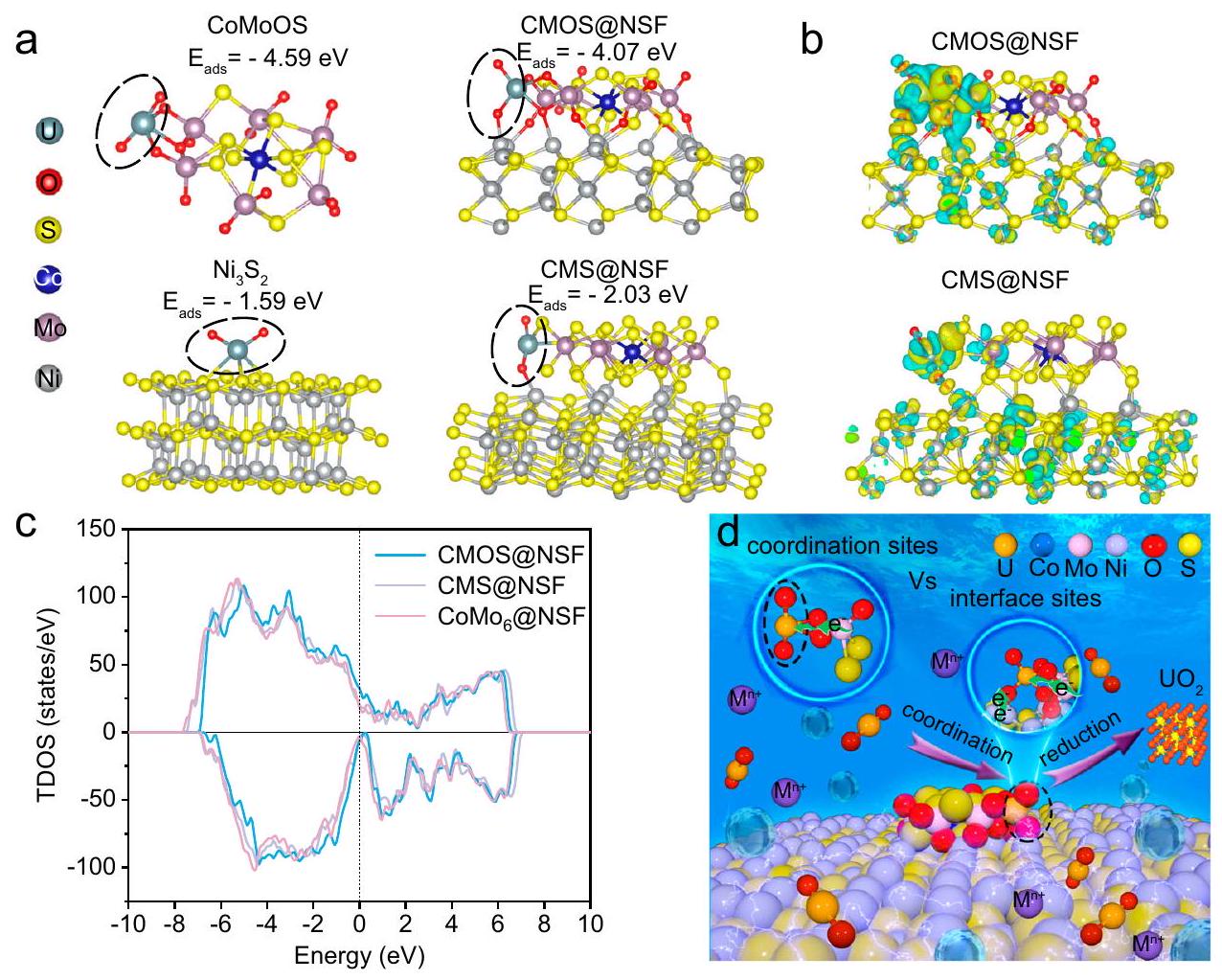
The ability of efficiently reducing and depositing ions as lowimpurity on CMOS@NSF motivates us to explore the underlying reaction mechanism. Considering that the adsorption of ions on the material surface is one of the key processes in uranium extraction, we first established a corresponding structural model and simulated the adsorption of ions on the synergistic coordination-reduction interface of CMOS@NSF. Meanwhile, we established adsorption models for ions on the fully sulfurized on (110) (CMS@NSF), CoMoOS and (110), respectively. As shown in Fig. 6a, the adsorption energy of on CMOS@NSF ( -4.07 eV ) was slightly higher than that on , but significantly lower than that on and CMS@NSF ( -2.03 eV ). These results demonstrated that the terminal oxygen plays an important role in “capturing” . Furthermore, after the adsorption of on the four models above, the bond angle of followed the order: (CoMoOS) (Supplementary Table 7). This result revealed that facilitated the reduction of the coordinated . By analyzing the differences in charge distribution after the adsorption of on different structures, we further explore the reduction and deposition mechanisms of on materials. As shown in Fig. 6b, a significant accumulation of electrons occurred on the terminal oxygen atoms in CoMoOS and the Ni atoms in , accompanied by the loss of electrons on the adsorbed ions. Compared with the CMS@NSF and CoMoOS structure, the CMOS@NSF structure exhibited a more pronounced charge transfer capability. Furthermore, partial density of states (PDOS) analysis, as shown in Fig. 6c, revealed the presence of more unoccupied Ni (5d) states above the Fermi level, while more
Fig. 6 | Reaction mechanism of interface sites. a Optimized adsorption configurations of on CMOS@NSF, CMS@NSF, CoMoOS and (110). b Charge density difference plots on CMS@NSF and CMOS@NSF. Yellow and cyan colors represent charge enrichment and depletion regions, respectively. c PDOS of the Ni
after H adsorption. The Fermi level is shifted to zero. Schematic mechanism of electrochemical uranium extraction from seawater using CMOS@NSF with a synergistic coordination-reduction interface. The regions enclosed by the elliptical outlines in (a, d) represent . Source data are provided as a Source Data file.
occupied states were observed below the Fermi level. This result was consistent with the calculated differential charge transfer from Ni atoms to the O atoms of .
Based on the analysis above, CMOS@NSF efficiently and stably reduced in seawater to low-impurity , attributing to the synergistic coordination-reduction interface. Figure 6d shown the schemes of the synergistic coordination-reduction interface site and the traditional coordination site in the electrochemical uranium extraction. Compared with the traditional coordination site, on the one hand, terminal oxygen pockets of CMOS@NSF served as strong coordination sites for binding. On the other hand, the Ni atoms in the synergistic coordination-reduction interface chemically bonded with the axial oxygen in and acted as a direct electron transport channel to promote the reduction of uranium. Consequently, was efficiently reduced to U(IV) at the synergistic coordinationreduction interface, avoiding the oxidation of U(IV) and subsequent co-deposition of alkali metals.
Discussion
In summary, we reported a synergistic coordination-reduction interface that successfully extracted low-impurity solids from seawater. The highly connected synergistic coordination-reduction interface was constructed via in-situ growth of sulfurized polyoxometalate- on . Comprehensive characterization and DFT calculations have demonstrated that the terminal oxygen pockets in the CoMoOS structure within this interface exhibit strong capture capabilities for . Additionally, the interfacial connection of CMOS with , where the Ni chemically bonded with the axial oxygen in , accelerated the electron transfer and promoted the reduction of to black solid products with low impurities from seawater. In the natural seawater experiment, CMOS@NSF
achieved a remarkable extraction efficiency of in 24 h, with an extraction capacity of in a self-assembled device for electrochemical uranium extraction from seawater. This work not only presents a material for electrochemical uranium extraction, but also provides an efficient strategy for the electrochemical uranium extraction from seawater with low impurities.
Methods
Chemicals and materials
Uranium nitrate purity), Ammonium molybdate tetrahydrate and cobalt(II) sulfate heptahydrate were purchased from Aladdin Industrial Co., Ltd. Hydrogen peroxide ( ) was purchased from Chengdu Cologne Chemical Reagents Co., Ltd. Thiourea and anhydrous sodium sulfate were purchased from Shanghai Macklin Biochemical Industrial Co., Ltd. Nafion membrane solution (NR50, ) was acquired from Shanghai Macklin Biochemical Co., Ltd.
Material synthesis
Synthesis of . First, dissolved ammonium molybdate tetrahydrate in boiling water . Then, poured in a solution containing cobalt (II) sulfate heptahydrate , 15 mmol ) into the boiling solution. Next, added while stirring, and boiled for 30 min . After that, cooled the mixture in a refrigerator to allow crystallization. Recrystallized the obtained crystals twice in water to obtain relatively pure .
Synthesis of CMOS@NSF. Synthesis of CMOS@NSF using a simple one-step hydrothermal method. In brief, added , 0.05 mmol ) obtained from the previous process into deionized water . Then, added thiourea and stirred for
15 min . Next, placed the NF ( ), which has been treated with hydrochloric acid, along with the above solution into a 50 ml stainless steel autoclave lined with polytetrafluoroethylene (PTFE). Performed a hydrothermal reaction at for 8 h . Finally, rinsed the obtained material with deionized water and ethanol, then dried it. To synthesize materials with different S:Mo ratios, adjusted the amount of thiourea added.
Synthesis of . Using the same method as described for synthesizing CMOS@NSF, but without adding .
Characterizations
XRD patterns of the samples were recorded by a PANalytical Empyrean X-ray diffractometer at 40 kV and 40 mA with radiation ( ). SEM images were conducted by a ZEISS Sigma 300 field-emission scanning electron microscopy. TEM and HRTEM images were collected on an FEI Teccnai G2 F20 field emission transmission electron microscope with an FEI 2 SDD energy disperse spectroscopy. XPS spectra were recorded by using a Thermo Scientific ESCALAB Xi+ photoelectron spectrometer with a monochromatic -ray source. EPR spectra were recorded by using an A300-10/12 Germany Bruker instrument. FT-IR measurements were performed on a PerkinElmer Spectrum One Fourier transform infrared spectrometer in a pressed KBr pellet. The oxidation states characterization of the samples was utilized by the XAFS through the transmission mode for O -edge, Mo -edge and U -edge in the National Synchrotron Radiation Laboratory (NSNR). The absorption edge positions were calibrated during the XAFS measurements. EXAFS data were collected from the ATHENA module, integrated within the IFEFIT software suite. Raman spectra were recorded by using a Renishaw InVia instrument. Inductive Coupled Plasma Emission Spec-trometer (ICP, Agilent, US) was used to record ion concentrations.
Theoretical calculations
The calculations were performed within the density functional theory (DFT) framework implanted in Vienna ab initio Simulation Package (VASP6.3.2) . The interaction between ions and electrons was described in the Projector Augmented Wave (PAW) Method . The electron exchange and correlation energy were described using the generalized gradient approximation-based Perdew-Burke-Erzenhorf (PBE) functional . The semi-empirical London dispersion corrections of Grimme and colleagues (DFT-D3) were conducted to calculate the interactions between absorbers and slabs . The Hubbard-U correction was applied for better description of the localized d-electrons of U. The values of the parameters of U, Co, Ni, and Mo are set to , and 2.3 respectively . The surface structure models of was built. Only the top three layers of atoms are relaxed in the calculation. A sufficiently large vacuum region of was used for all the models to ensure the periodic images were well separated. The Brillouin-zone integrations were carried out using MonkhorstPack grids of special points. A gamma-centered ( ) k-point grid were used for models. To obtain the accurate structure, the planewave cutoff energy was set up to 500 eV . The force convergence was set to be , and the total energy convergence was set to be .
Electrochemical testing
All electrochemical tests were conducted using a CHI660E electrochemical workstation. The procedures are as follows. CMOS@NSF or piece was used directly as working electrode. For powder was weighed, dispersed in 2 mL ethanol with Nafion solution, and treated by ultrasonic for 0.5 h to get a catalytic ink solution. Then the ink solution was brushed onto a carbon felt (CF) as the work electrode. A three-electrode system was used for testing, with the prepared materials as the working electrode, an electrode as the
reference electrode, and a platinum wire electrode as the counter electrode. LSV tests were conducted in solution in the presence or absence of , at a scanning rate of in the potential range of 0 to -1.6 V (vs ). CV tests were conducted in solution in the presence or absence of , at different scanning rates ( , and ) in the potential range of 0.2 to -1.2 V (vs ). EIS testing was conducted in a solution in a frequency range of 0.1 Hz to 100 kHz .
Electrochemical extraction of uranium experiments in uraniumspiked seawater
The uranium extraction experiments from uranium-spiked seawater were conducted using a three-electrode system. Various electrode materials were prepared using the materials mentioned above for the working electrode. Platinum (Pt) wire and electrodes were used as the counter electrode and reference electrode, respectively. The uranium extraction was performed under a constant potential of -1.4 V . The effects of different initial uranium concentrations ( 8,50 , and ) and various interfering ions on the electrochemical uranium extraction performance were measured. The concentrations of uranium and other cations in the electrolyte after electrochemical extraction were determined using ICP. During the desorption process, the uranium-loaded working electrode was analyzed for 10 min at 1.4 V reverse potential in . The extraction experiments were performed in triplicate, and error bars were included in the curves.
Physical adsorption experiments of uranium
Physical adsorption experiments of , and for uranium were carried out without applying an external potential. Each of the three materials was placed in 100 mL solution of seawater spiked with uranium at a stirring speed of .
Electrochemical extraction experiments of uranium in natural seawater
The electrochemical extraction experiment of uranium from natural seawater was also conducted using a three-electrode system. The working electrode was prepared using the same method as described for CMOS@NSF, with a proportional scaling to . The reference electrode and counter electrode were the same as described above. The experiment was carried out on a simply self-assembled device for uranium extraction using 25 L of real seawater. Before uranium extraction, the seawater was filtered via a vacuum filtration operation. The seawater circulation flow rate was controlled at . After 24 h of electrochemical uranium extraction, the electrode material was removed, first rinsed with pure water, and then soaked in 0.5 M HCl to elute the extracted uranium. Then, the solution was prepared into a 10 mL concentrated solution. The uranium content in the elution solution was measured by ICP, and the extraction capacity was calculated.
Calculations
For quantifying the extraction efficiency ( ), the uranium extraction capacity ( ), and adsorption energy ( ) were calculated according to the following equations:
Where and represent the initial and final uranium concentration, respectively.
Where and represent the mass of uranium extracted from the electrode and the mass of the electrode material, respectively; represent the electrochemical uranium extraction time.
Where , and are the total energies of the adsorbate-substrate (AS), substrate (S), and adsorbate (A), respectively.
Data availability
The data that supports the findings of the study are included in the main text and supplementary information files. Source data are provided with this paper. Source Data files are available in Figshare under accession code https://doi.org/10.6084/m9.figshare.28142705.
References
Mei, D., Liu, L. & Yan, B. Adsorption of uranium (VI) by metal-organic frameworks and covalent-organic frameworks from water. Coord. Chem. Rev. 475, 214917 (2023).
Hu, Y. et al. Photochemically triggered self-extraction of uranium from aqueous solution under ambient conditions. Appl. Catal. B Environ. 322, 122092 (2023).
Abney, C. W., Mayes, R. T., Saito, T. & Dai, S. Materials for the recovery of uranium from seawater. Chem. Rev. 117, 13935-14013 (2017).
Xie, Y. et al. Uranium extraction from seawater: material design, emerging technologies and marine engineering. Chem. Soc. Rev. 52, 97-162 (2023).
Lin, L. et al. Electrocatalytic removal of low-concentration uranium using nanotube arrays/Ti mesh electrodes. Environ. Sci. Technol. 56, 13327-13337 (2022).
Liu, C. et al. A half-wave rectified alternating current electrochemical method for uranium extraction from seawater. Nat. Energy 2, 17007 (2017).
Chi, F., Zhang, S., Wen, J., Xiong, J. & Hu, S. Highly efficient recovery of uranium from seawater using an electrochemical approach. Ind. Eng. Chem. Res. 57, 8078-8084 (2018).
Liu, T. et al. Removal and recovery of uranium from groundwater using direct electrochemical reduction method: performance and implications. Environ. Sci. Technol. 53, 14612-14619 (2019).
Zhou, L. et al. Interface coupling induced built-in electric fields accelerate electro-assisted uranium extraction over nanosheet arrays. Appl. Catal. B Environ. 353, 124052 (2024).
Lin, T. et al. Ion pair sites for efficient electrochemical extraction of uranium in real nuclear wastewater. Nat. Commun. 15, 4149 (2024).
Yang, H. et al. Functionalized iron-nitrogen-carbon electrocatalyst provides a reversible electron transfer platform for efficient uranium extraction from seawater. Adv. Mater. 33, 2106621 (2021).
Yang, S. et al. Electro-adsorption and reduction of uranium(VI) by @COFs electrode with enhanced removal performance. Chem. Eng. J. 474, 145598 (2023).
Liu, X. et al. Highly efficient electrocatalytic uranium extraction from seawater over an amidoxime-functionalized In-N-C Catalyst. Adv. Sci. 9, 2201735 (2022).
Zhou, L. et al. Unveiling the critical role of surface hydroxyl groups for electro-assisted uranium extraction from wastewater. Inorg. Chem. 62, 21518-21527 (2023).
Liu, X. et al. Secondary metal ion-induced electrochemical reduction of U(VI) to U(IV) solids. Nat. Commun. 15, 7736 (2024).
Feng, J. X., Wu, J. Q., Tong, Y. X. & Li, G. R. Efficient hydrogen evolution on Cu nanodots-decorated nanotubes by optimizing atomic hydrogen adsorption and desorption. J. Am. Chem. Soc. 140, 610-617 (2018).
Du, H. et al. Mountain-shaped nickel nanostripes enabled by facet engineering of nickel foam: a new platform for high-current-density water splitting. Adv. Funct. Mater. 34, 2311854 (2024).
Zhai, P. et al. Engineering active sites on hierarchical transition bimetal oxides/sulfides heterostructure array enabling robust overall water splitting. Nat. Commun. 11, 5462 (2020).
Reddy, M. A., Ramulu, B. & Su, Y. J. Tri-metallic core-shell structures by confining crystalline nanorod and amorphous nanosheet architectures for high-performance hybrid supercapacitors. Chem. Eng. J. 451, 139018 (2023).
Nguyen, D. C. et al. Rh single atoms/clusters confined in metal sulfide/oxide nanotubes as advanced multifunctional catalysts for green and energy-saving hydrogen productions. Appl. Catal. B: Environ. 313, 121430 (2022).
Zhou, Z. et al. Intercalation-activated layered nanobelts as biodegradable nanozymes for tumor-specific photo-enhanced catalytic therapy. Angew. Chem. Int. Ed. 61, e202115939 (2022).
Weber, T., Muijsers, J. C., Wolput, J., Verhagen, C. & Niemantsverdriet, J. Basic reaction steps in the sulfidation of crystalline to , as studied by X-ray photoelectron and infrared emission spectroscopy. J. Phys. Chem. 100, 14144-14150 (1996).
Tran, P. D. et al. Coordination polymer structure and revisited hydrogen evolution catalytic mechanism for amorphous molybdenum sulfide. Nat. Mater. 15, 640-646 (2016).
Dai, J. et al. @polyaniline for aqueous ammonium-ion supercapacitors. Adv. Mater. 35, 2303732 (2023).
Ren, H. et al. Facile synthesis of free-standing nickel chalcogenide electrodes for overall water splitting. J. Energy. Chem. 26, 1217-1222 (2017).
Tang, X. et al. Sulfur edge in molybdenum disulfide nanosheets achieves efficient uranium binding and electrocatalytic extraction in seawater. Nanoscale 14, 6285-6290 (2022).
Shao, M. et al. High-performance biodegradable energy storage devices enabled by heterostructured composites. Small 19, 2205529 (2023).
Ma, H., Sun, C., Wang, Z. & Jiang, Q. Tuning the electronic structure of nanosheets through S doping for enhanced oxygen evolution. Nanoscale 13, 17022-17027 (2021).
Guo, Z. et al. Defect engineering associated with cationic vacancies for promoting electrocatalytic water splitting in iron-doped nanosheet arrays. J. Colloid. Interf. Sci. 654, 785-794 (2024).
Liu, X. et al. Tunable cationic vacancies of cobalt oxides for efficient electrocatalysis in batteries. Adv. Energy. Mater. 10, 2001415 (2020).
Yu, H. et al. Transition-metal-controlled inorganic ligand-supported non-precious metal catalysts for the aerobic oxidation of amines to imines. Chem-Eur. J. 23, 13883-13887 (2017).
Nomiya, K., Takahashi, T., Shirai, T. & Miwa, M. Anderson-type heteropolyanions of molybdenum(VI) and tungsten(VI). Polyhedron 6, 213-218 (1987).
Gao, Y., Wang, M. & Zhang, G. Effect of calcium ions on the surface properties of heterogenite and conducive to sulfidization flotation: Insight from oxygen vacancy. Appl. Surf. Sci. 640, 158328 (2023).
Huang, Y. et al. Atomically engineering activation sites onto metallic 1T-MoS catalysts for enhanced electrochemical hydrogen evolution. Nat. Commun. 10, 982 (2019).
Bradley, J. A. et al. Experimental and theoretical comparison of the O K-edge nonresonant inelastic X-ray scattering and X-ray absorption spectra of . J. Am. Chem. Soc. 132, 13914-13921 (2010).
Song, W. et al. Pseudocapacitive insertion in channels of -C nanofibers with high rate and ultrastable performance. ACS Appl. Mater. Interfaces 11, 17416-17424 (2019).
Sun, S. et al. Lattice pinning in via coherent interface with stabilized intercalation. Nat. Commun. 14, 6662 (2023).
Yu, Z. Y. et al. General synthesis of tube-like nanostructured perovskite oxides with tunable transition metal-oxygen covalency for efficient water electrooxidation in neutral media. J. Am. Chem. Soc. 144, 13163-13173 (2022).
Zhang, B. W. et al. Atomically dispersed dual-site cathode with a record high sulfur mass loading for high-performance room-temperature sodium-sulfur batteries. Adv. Mater. 35, 2206828 (2023).
Wu, H. C. et al. Antiferroelectric antiferromagnetic type-I multiferroic . Phys. Rev. B 100, 245119 (2019).
Huang, J., Liu, Z., Huang, D., Jin, T. & Qian, Y. Electrochemical deposition of uranium oxide with an electrocatalytically active electrode using double potential step technique. Chinese. Chem. Lett. 33, 3762-3766 (2022).
Hao, M. et al. Converging cooperative functions into the nanospace of covalent organic frameworks for efficient uranium extraction from seawater. CCS Chemistry 4, 2294-2307 (2022).
Zhu, Q. et al. A new view of supercapacitors: integrated supercapacitors. Adv. Energy. Mater. 9, 1901081 (2019).
Liao, Y. et al. Uranium capture by a layered 2D/2D niobium phosphate/holey graphene architecture via an electro-adsorption and electrocatalytic reduction coupling process. J. Hazard. Mater. 442, 130054 (2023).
Wu, X. et al. Sol-gel transition effect based on konjac glucomannan thermosensitive hydrogel for photo-assisted uranium extraction. Sci. Bull. 69, 3042-3054 (2024).
Blake, A. J. et al. A new home for studies of crystal growth and characterisation. Acta. Crystallogr. B 77, 456-457 (2021).
Dewey, C., Sokaras, D., Kroll, T., Bargar, J. R. & Fendorf, S. Calcium-uranyl-carbonato species kinetically limit U(VI) reduction by Fe(II) and lead to -bearing ferrihydrite. Environ. Sci. Technol. 54, 6021-6030 (2020).
Wei, H. et al. Iced photochemical reduction to synthesize atomically dispersed metals by suppressing nanocrystal growth. Nat. Commun. 8, 1490 (2017).
Kresse, G. & Furthmüller, J. Efficient iterative schemes for ab initio total-energy calculations using a plane-wave basis set. Phys. Rev. B 54, 11169-11186 (1996).
Blöchl, P. E. Projector augmented-wave method. Phys. Rev. B 50, 17953-17979 (1994).
Perdew, J. P., Burke, K. & Ernzerhof, M. Generalized gradient approximation made simple. Phys. Rev. Lett. 77, 3865-3868 (1996).
Grimme, S. Semiempirical GGA-type density functional constructed with a long-range dispersion correction. J. Comput. Chem. 27, 1787-1799 (2006).
Wiktor, J. et al. Coupled experimental and DFT + U investigation of positron lifetimes in . Phys. Rev. B 90, 184101 (2014).
Acknowledgements
This work was supported by NSFC (No. U23A2O105 and U2267224, W.Z.), Sichuan Science and Technology Program (No. 2024NSFTDOO12, W.Z. and 2025ZNSFSCO949, H.L.), Seawater Uranium Extraction Alliance Innovation and Development Fund (W.Z.), the Project of State Key Laboratory of Environment-friendly Energy Materials in SWUST (No.
21fksy22, W.Z.) and the Research Fund of SWUST for PhD (No. 23zx7110, H.L.). The authors express their gratitude to the Theoretical and Computational Chemistry Team at Shiyanjia Lab (www.shiyanjia.com) for their invaluable assistance. Additionally, the authors acknowledge Shiyanjia Lab (www.shiyanjia.com) for providing invaluable support with SEM, TEM, and XPS analysis.
Author contributions
H.G. made the most important contributions, although all authors made contributions to the work. H.G., R.H., and H.L. designed the studies and wrote the paper. H.G. performed most of the experiments. E.H., Y.W., Z.O., and B.H. performed part of the experiments. W.Z. provided advice and reagents. J.L. performed DFT calculations. H.L., R.H., and W.Z. supervised the research. All authors contributed to data analysis and commented on the manuscript.
Correspondence and requests for materials should be addressed to Huanhuan Liu, Rong He or Wenkun Zhu.
Peer review information Nature Communications thanks the anonymous reviewers for their contribution to the peer review of this work. A peer review file is available.
Publisher’s note Springer Nature remains neutral with regard to jurisdictional claims in published maps and institutional affiliations.
Open Access This article is licensed under a Creative Commons Attribution-NonCommercial-NoDerivatives 4.0 International License, which permits any non-commercial use, sharing, distribution and reproduction in any medium or format, as long as you give appropriate credit to the original author(s) and the source, provide a link to the Creative Commons licence, and indicate if you modified the licensed material. You do not have permission under this licence to share adapted material derived from this article or parts of it. The images or other third party material in this article are included in the article’s Creative Commons licence, unless indicated otherwise in a credit line to the material. If material is not included in the article’s Creative Commons licence and your intended use is not permitted by statutory regulation or exceeds the permitted use, you will need to obtain permission directly from the copyright holder. To view a copy of this licence, visit http:// creativecommons.org/licenses/by-nc-nd/4.0/.
(c) The Author(s) 2025
State Key Laboratory of Environment-friendly Energy Materials, School of National Defense & Nuclear Science and Technology, School of Materials & Chemistry, CAEA Innovation Center of Nuclear Environmental Safety Technology, Southwest University of Science & Technology, Mianyang, PR China. School of Chemistry and Chemical Engineering, Nanchang University, Nanchang, PR China. e-mail: Liuhuanhuan@swust.edu.cn; her@swust.edu.cn; zhuwenkun@swust.edu.cn