DOI: https://doi.org/10.1186/s40001-024-01681-2
PMID: https://pubmed.ncbi.nlm.nih.gov/38287445
تاريخ النشر: 2024-01-29
التوطين الآلي لنقاط المعالم الفكية في بناء المستوى السهمي الوسيط الفكي
الملخص
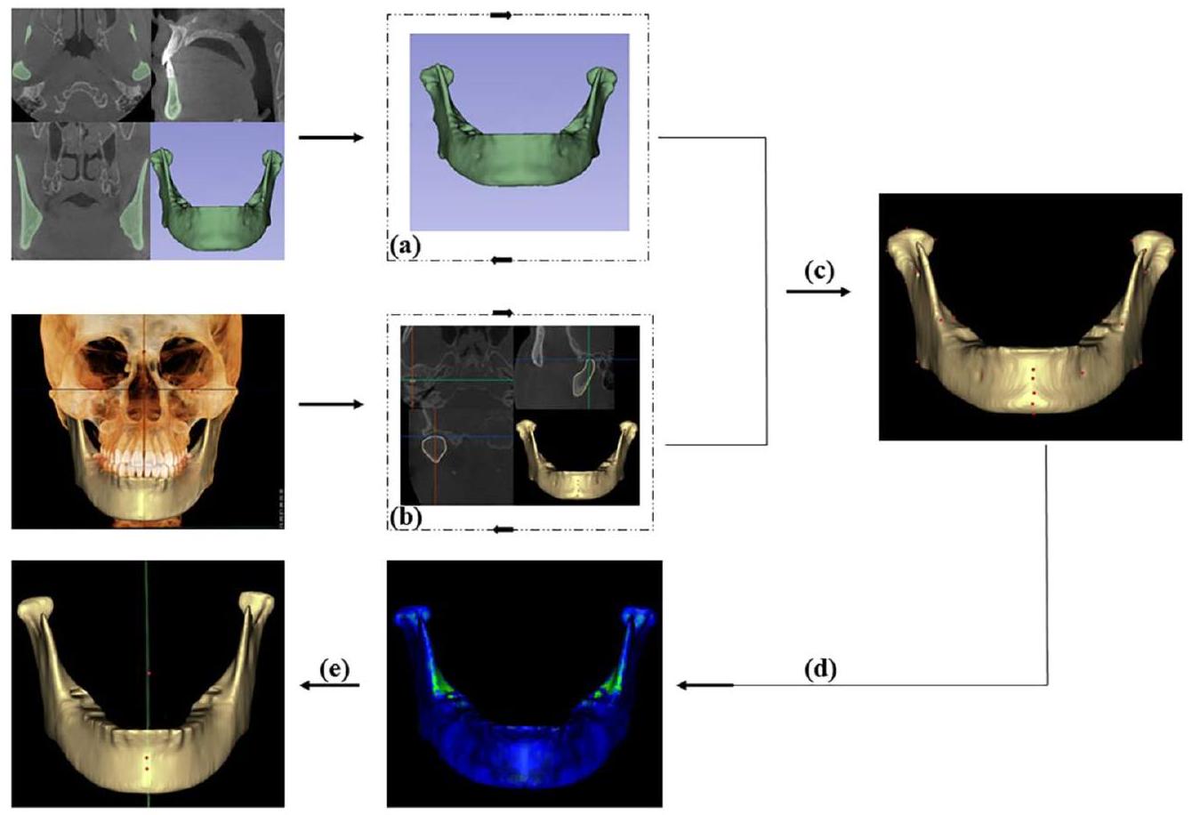
الهدف هو استخدام التعلم العميق لتقسيم الفك السفلي وتحديد المعالم التشريحية ثلاثية الأبعاد (3D) من صور الأشعة المقطعية المخروطية (CBCT)، وتمت مقارنة وتحليل المستويات المكونة من معالم منتصف الفك السفلي للعثور على أفضل مستوى متوسط للفك السفلي (MMSP). الطرق تم تقسيم 400 مشارك بشكل عشوائي إلى مجموعة تدريبية (
النتائج تم تقسيم الفك السفلي تلقائيًا في
مقدمة
مع التطور السريع لتكنولوجيا الكمبيوتر وإعادة البناء ثلاثي الأبعاد، تتمتع طرق القياس ثلاثي الأبعاد بمزيد من المزايا مقارنة بالطرق ثنائية الأبعاد (2D) لتقييم عدم التماثل. تعتمد طرق تحليل تماثل الوجه والجمجمة بشكل أساسي على المعالم التشريحية، ومحاذاة الأصل-المرآة، وخوارزميات التعلم العميق. كانت الطرق التقليدية المعتمدة على المعالم التشريحية الخيار الرئيسي لتقييم عدم تماثل الوجه والجمجمة. غالبًا ما يتم إنشاء مستوى مرجعي عن طريق تقسيم الخطوط بين المعالم الثنائية أو عن طريق ربط المعالم المتوسطة، والتي تحدد كلا الجانبين من القياسات الكمية ثنائية أو ثلاثية الأبعاد. لقد قامت عدة دراسات بتحليل المستويات التي تم إنشاؤها بواسطة
استنادًا إلى مجموعة بيانات ShapeNet، تم أتمتة إنشاء بيانات سحابة النقاط ثلاثية الأبعاد لسطح التماثل، والذي تم استخدامه كمرجع مهم للتوليد الآلي لسطح السهم الوسيط للوجه.
طرق
جمع البيانات
استحواذ الصورة
تطوير PointRend و PoseNet
تخطيط القالب
تقييم MMSP
التحليل الإحصائي
تم استخدامه لمقارنة الفروق المتوسطة بين قياسات المستوى المرجعي والمستوى السهمي.
النتائج
تقييم النموذج
دقة تحديد المعالم
| معلم | خطأ متوسط (مم) | خطأ المعيار للمتوسط (مم) |
| أنا | 0.61 | 0.18 |
| ب | 0.43 | 0.28 |
| كور (يمين) | 0.61 | 0.28 |
| ج | 0.65 | 0.19 |
| بوج | 0.66 | 0.42 |
| كونمد (يسار) | 0.72 | 0.30 |
| MF (يسار) | 0.77 | 0.26 |
| توقيع (يسار) | 0.79 | 0.22 |
| تصبح على خير | 0.79 | 0.39 |
| MF (يسار) | 0.80 | 0.22 |
| توقيع (يمين) | 0.90 | 0.28 |
| جلط (يمين) | 0.94 | 0.15 |
| كور (يسار) | 1.17 | 0.35 |
| كونسوب (يمين) | 1.18 | 0.28 |
| اذهب (يسار) | 1.19 | 0.41 |
| جميد (يسار) | 1.21 | 0.35 |
| جميد (يمين) | 1.22 | 0.19 |
| كونمد (يمين) | 1.22 | 0.38 |
| اذهب (يميناً) | 1.23 | 0.13 |
| RP (اليمين) | 1.29 | 0.38 |
| كونسوب (يسار) | 1.30 | 0.24 |
| كونلات (يسار) | 1.32 | 0.34 |
| F (يمين) | 1.37 | 0.13 |
| F (يسار) | 1.39 | 0.21 |
| RP (يسار) | 1.41 | 0.44 |
| جلط (يسار) | 1.45 | 0.27 |
| كونلات (يمين) | 1.52 | 0.28 |
تقييم الطائرة
نقاش
| معلم1 | معلم2 | لاند مارك 3 | الوسيط (المدى interquartile) | مين-ماكس |
| ب | تصبح على خير | ف | 1.6(1.53-1.92) | 0.59-3.61 |
| ب | أنا | ف | 1.95(1.81-2.34) | 1.05-3.61 |
| ب | بوج | ف | 1.97(1.75-2.19) | 0.73-5.05 |
| ب | ج | ف | 2.15(1.88-2.81) | 0.68-5.38 |
| ب | ف | MF | 2.34(2.22-3.11) | 0.69-4.34 |
| .. | .. | .. | .. | .. |
| .. | .. | .. | .. | .. |
| ب | ج | أنا | 7.49(7.24-10.3) | 1.56-19.97 |
| .. | .. | .. | .. | .. |
| .. | .. | .. |
|
.. |
| ب | ج | MF | 12.57(9.45-16.76) | 1.58-41.71 |
| ب | تصبح على خير | أنا | 12.97(11.67-15.82) | 1.34-37.4 |
| ج | أنا | MF | 17.78(18.4425.32) | 1.81-36.82 |
| ب | بوج | تصبح على خير | 18.76(17.2525.92) | 0.94-53.46 |
| بوج | تصبح على خير | أنا | 21.15(18.4933.68) | 1.7-64.04 |
| معلم | طائرة المرجع (مم) | ب-جن-ف(مم) | ب-بوج-ف(مم) | ب-مي-ف(مم) | ب-ج-ف (مم) |
| كونسب |
|
|
|
|
|
| كونمد |
|
|
|
|
|
| كونلات |
|
|
|
|
|
| توقيع |
|
|
|
|
|
| كور |
|
|
|
|
|
| اذهب |
|
|
|
|
|
| RP |
|
|
|
|
|
| MF |
|
|
|
|
|
| جلط |
|
|
|
|
|
| جميد |
|
|
|
|
|
| ف | – |
|
|
|
|
| معنى |
|
|
|
|
|
| طائرة | حجم (
|
قيمة P | مؤشر التشابه | قيمة P |
| مرجع |
|
– |
|
– |
| ب-جن-ف |
|
0.671 |
|
** |
| بي-بوج-إف |
|
0.560 |
|
** |
| ب-مي-ف |
|
0.438 |
|
** |
| ب-ج-ف |
|
0.537 |
|
** |
| *
|
||||
|
|
||||
تقسيم صور CBCT عالية الدقة في 17 ثانية، وهو ما يمثل تقليصًا بمقدار 71.3 مرة مقارنة بالتقسيم شبه الآلي. أنشأ روبرت وزملاؤه برنامج تقسيم داخلي زاد من دقة التقسيم إلى
يمكن استخراج حدود الفك السفلي الأكثر اكتمالاً من خلال زيادة حجم النقاط الحافة فقط في نهاية النموذج باستخدام المعلومات متعددة المستويات للشبكة دون التأثير على معظم بكسلات المقدمة.
تُعبر المعالم التشريحية ثلاثية الأبعاد عن الخصائص الشكلية للفك السفلي وهي أساس التحليل ثلاثي الأبعاد للفك السفلي. يعتمد تحديد المعالم يدويًا على خبرة الأطباء السريرية وهو أمر شاق [24،25]. تم تطبيق خوارزمية You-Only Look-Once النسخة 3 (YOLOv3) على 1028 صورة شعاعية لتحديد 80 معلمًا شعاعيًا تلقائيًا بمتوسط خطأ يدوي للمعالم قدره
السطح الكامل للفك السفلي [4]. لم يتم اختيار ICP كطائرة مرجعية لأنه على الرغم من أن كلا الطريقتين تستخدمان قيمة الجذر التربيعي المتوسط، فإن خوارزمية ICP تحسب أقرب مسافة بين النموذج الأصلي ونموذج المرآة، بينما تحسب طريقة رسم الخرائط القالب المسافة بين النموذج الأصلي والمعالم شبه المطابقة في المرآة، مما له مزايا المزيد من النقاط، والذكاء، وعلاقات المطابقة الجيدة [9]. عندما كان الفك السفلي غير متماثل بشدة، انخفضت دقة خوارزمية ICP [4]. استخدمت العديد من الدراسات السابقة مستوى B-G-Me كـ MMSP لدراسة تماثل الفك السفلي [5، 6]. أظهرت نتائج الدراسة الحالية أن AI لمستوى B-G-Me كان 7.49 (الجدول 2)، والذي اختلف بشكل كبير عن النتائج التي تم الحصول عليها لمستوى
الاستنتاجات
الاختصارات
| CBCT | التصوير المقطعي المحوسب باستخدام شعاع مخروط |
| MMSP | المستوى السهمي الأوسط للفك السفلي |
| AI | مؤشر عدم التماثل |
| 3D | ثلاثي الأبعاد |
| 2D | ثنائي الأبعاد |
| CMSP | المستوى السهمي الوسيط القحفي الفكي |
| ICC | معامل الارتباط داخل الفئة |
| ICP | نقطة الأقرب التكرارية |
| WPA | تحليل بروكروستس الموزون |
المعلومات التكميلية
الشكر والتقدير
مساهمات المؤلفين
التمويل
توفر البيانات والمواد
الإعلانات
موافقة الأخلاقيات والموافقة على المشاركة
المرضى/المشاركون موافقتهم الخطية المستنيرة للمشاركة في هذه الدراسة.
الموافقة على النشر
المصالح المتنافسة
تفاصيل المؤلف
تم النشر على الإنترنت: 29 يناير 2024
References
- Fang JJ, Tu YH, Wong TY, Liu JK, Zhang YX, Leong IF, et al. Evaluation of mandibular contour in patients with significant facial asymmetry. Int J Oral Maxillofac Surg. 2016;45(7):922-31.
- Kwon SM, Hwang JJ, Jung YH, Cho BH, Lee KJ, Hwang CJ, et al. Similarity index for intuitive assessment of three-dimensional facial asymmetry. Sci Rep. 2019;9(1):10959.
- AlHadidi A, Cevidanes LH, Mol A, Ludlow J, Styner M. Comparison of two methods for quantitative assessment of mandibular asymmetry using cone beam computed tomography image volumes. Dentomaxillofac Radiol. 2011;40(6):351-7.
- Fan Y, Zhang Y, Chen G, He W, Song G, Matthews H, et al. Automated assessment of mandibular shape asymmetry in 3-dimensions. Am J Orthod Dentofacial Orthop. 2022;161(5):698-707.
- You KH, Lee KJ, Lee SH, Baik HS. Three-dimensional computed tomography analysis of mandibular morphology in patients with facial asymmetry and mandibular prognathism. Am J Orthod Dentofacial Orthop. 2010;138(5):540.e1-8.
- Kim SJ, Lee KJ, Lee SH, Baik HS. Morphologic relationship between the cranial base and the mandible in patients with facial asymmetry and mandibular prognathism. Am J Orthod Dentofacial Orthop. 2013;144(3):330-40.
- Pittayapat P, Jacobs R, Bornstein MM, Odri GA, Kwon MS, Lambrichts I, et al. A new mandible-specific landmark reference system for threedimensional cephalometry using cone-beam computed tomography. Eur J Orthod. 2016;38(6):563-8.
- Xiong Y, Zhao Y, Yang H, Sun Y, Wang Y. Comparison between interactive closest point and procrustes analysis for determining the median sagittal plane of three-dimensional facial data. J Craniofac Surg. 2016;27(2):441-4.
- Zhu Y, Zhao Y, Wang Y. A review of three-dimensional facial asymmetry analysis methods. Symmetry. 2022;14(7):1414.
- Zhu YJ, Zhao YJ, Zheng SW, Wen AN, Fu XL, Wang Y. A method for constructing three-dimensional face symmetry reference plane based on weighted shape analysis algorithm. Beijing da xue xue bao Yi xue ban
Journal of Peking University Health sciences. 2020;53(1):220-6. - Gao L, Zhang LX, Meng HY, Ren YH, Lai YK, Kobbelt L. PRS-net: planar reflective symmetry detection net for 3d models. IEEE transactions on visualization and computer graphics 2021;27(6):3007-18.
- Verhelst P-J, Matthews H, Verstraete L, Van der Cruyssen F, Mulier D, Croonenborghs TM, et al. Automatic 3D dense phenotyping provides reliable and accurate shape quantification of the human mandible. Scientific Reports 2021;11(1).
- Fan Y, Schneider P, Matthews H, Roberts WE, Xu T, Wei R, et al. 3D assessment of mandibular skeletal effects produced by the Herbst appliance. BMC Oral Health. 2020;20(1):117.
- Moon JH, Hwang HW, Yu Y, Kim MG, Donatelli RE, Lee SJ. How much deep learning is enough for automatic identification to be reliable? Angle Orthod. 2020;90(6):823-30.
- Le C, Deleat-Besson R, Prieto J, Brosset S, Dumont M, Zhang W, et al. Automatic segmentation of mandibular ramus and condyles. Annu Int Conf IEEE Eng Med Biol Soc. 2021Nov:2021:2952-5.
- Qiu B, Guo J, Kraeima J, Glas HH, Borra RJH, Witjes MJH, et al. Automatic segmentation of the mandible from computed tomography scans for 3D virtual surgical planning using the convolutional neural network. Phys Med Biol. 2019;64(17):175020.
- Vinayahalingam S, Berends B, Baan F, Moin DA, van Luijn R, Berge S, et al. Deep learning for automated segmentation of the temporomandibular joint. J Dent. 2023;132: 104475.
- Verhelst PJ, Smolders A, Beznik T, Meewis J, Vandemeulebroucke A, Shaheen E, et al. Layered deep learning for automatic mandibular segmentation in cone-beam computed tomography. J Dent. 2021;114:103786.
- Lo Giudice A, Ronsivalle V, Spampinato C, Leonardi R. Fully automatic segmentation of the mandible based on convolutional neural networks (CNNs). Orthod Craniofac Res. 2021;24 Suppl 2 :100-7.
- Ilesan RR, Beyer M, Kunz C, Thieringer FM. Comparison of artificial intelligence-based applications for mandible segmentation: from established platforms to in-house-developed software. Bioengineering. 2023;10(5):604.
- MinJin Hwang BD, Enrique Dehaerne, Sandip Halder, Young-han Shin. SEMI-PointRend: Improved Semiconductor Wafer Defect Classification and Segmentation as Rendering. arXiv – CS – Computer Vision and Pattern Recognition. 2023.
- Girshick AKYWKHR. PointRend: Image Segmentation as Rendering. arXiv CS – Computer Vision and Pattern Recognition 2019.
- Dong Y, Zhang Y, Hou Y, Tong X, Wu Q, Zhou Z, et al. Damage recognition of road auxiliary facilities based on deep convolution network for segmentation and image region correction. Advances in Civil Engineering. 2022;2022:1-10.
- Blum FMS, Mohlhenrich SC, Raith S, Pankert T, Peters F, Wolf M, et al. Evaluation of an artificial intelligence-based algorithm for automated localization of craniofacial landmarks. Clin Oral Investig. 2023;27(5):2255-65.
- Hwang HW, Park JH, Moon JH, Yu Y, Kim H, Her SB, et al. Automated identification of cephalometric landmarks: part 2-might it be better than human? Angle Orthod. 2020;90(1):69-76.
- Zhang J, Liu M, Wang L, Chen S, Yuan P, Li J, et al. Context-guided fully convolutional networks for joint craniomaxillofacial bone segmentation and landmark digitization. Med Image Anal. 2020;60:101621.
- Dot G, Schouman T, Chang S, Rafflenbeul F, Kerbrat A, Rouch P, et al. Automatic 3-dimensional cephalometric landmarking via deep learning. J Dent Res. 2022;101(11):1380-7.
- Schlicher W, Nielsen I, Huang JC, Maki K, Hatcher DC, Miller AJ. Consistency and precision of landmark identification in three-dimensional cone beam computed tomography scans. Eur J Orthod. 2012;34(3):263-75.
- Dobai A, Markella Z, Vízkelety T, Fouquet C, Rosta A, Barabás J. Landmarkbased midsagittal plane analysis in patients with facial symmetry and asymmetry based on CBCT analysis tomography.Journal of Orofacial Orthopedics / Fortschritte der Kieferorthopädie. 2018;79(6):371-9.
- Gada SK. Assessment of position and bilateral symmetry of occurrence of mental foramen in dentate Asian population. Journal of Clinical and Diagnostic Research. 2014;8(2):203-5
- Findik Y, Yildirim D, Baykul T. Three-dimensional anatomic analysis of the lingula and mandibular foramen. Journal of Craniofacial Surgery. 2014;25(2):607-10.
- Lo Giudice A, Ronsivalle V, Rustico L, Aboulazm K, Isola G, Palazzo G. Evaluation of the accuracy of orthodontic models prototyped with entry-level LCD-based 3D printers: a study using surface-based superimposition and deviation analysis. Clin Oral Investig. 2022;26(1):303-12.
- Lo Giudice A, Ronsivalle V, Santonocito S, Lucchese A, Venezia P, Marzo G, et al. Digital analysis of the occlusal changes and palatal morphology using elastodontic devices. A prospective clinical study including Class II subjects in mixed dentition. Eur J Paediatr Dent. 2022;23(4):275-80
- Green MN, Bloom JM, Kulbersh R. A simple and accurate craniofacial midsagittal plane definition. Am J Orthod Dentofacial Orthop. 2017;152(3):355-63.
- Duran GS, Dindaroglu F, Kutlu P. Hard- and soft-tissue symmetry comparison in patients with class III malocclusion. Am J Orthod Dentofacial Orthop. 2019;155(4):509-22.
- Lo Giudice A, Ronsivalle V, Gastaldi G, Leonardi R. Assessment of the accuracy of imaging software for 3D rendering of the upper airway, usable in orthodontic and craniofacial clinical settings. Prog Orthod. 2022;23(1):22.
ملاحظة الناشر
قد ساهم يالي وانغ وويزي وو بالتساوي في هذا العمل.
*المراسلة:
يفان لين
yflin@hku.hk
هينغ قوه تشانغ
zhanghengguo@ahmu.edu.cn
جيانغوانغ شيو
xujg1982@connect.hku.hk
قائمة كاملة بمعلومات المؤلفين متاحة في نهاية المقالةنطاق الربع المتداخل (الربع 25، 75)؛ الحد الأدنى؛ الحد الأقصى؛
DOI: https://doi.org/10.1186/s40001-024-01681-2
PMID: https://pubmed.ncbi.nlm.nih.gov/38287445
Publication Date: 2024-01-29
Automated localization of mandibular landmarks in the construction of mandibular median sagittal plane
Abstract
Objective To use deep learning to segment the mandible and identify three-dimensional (3D) anatomical landmarks from cone-beam computed tomography (CBCT) images, the planes constructed from the mandibular midline landmarks were compared and analyzed to find the best mandibular midsagittal plane (MMSP). Methods A total of 400 participants were randomly divided into a training group (
Results The mandible was segmented automatically in
Introduction
With the rapid development of computer and 3D reconstruction technology, 3D measurement methods have more advantages than two-dimensional (2D) methods for asymmetry evaluation [2, 4]. The methods for craniofacial symmetry analysis are based mainly on anatomical landmarks, original-mirror alignment, and deep learning algorithms. Conventional anatomic landmark approaches used to be the main option for evaluating craniofacial asymmetry. A reference plane is frequently created by dividing the lines between bilateral landmarks or by connecting median landmarks, which determine both sides of 2D or 3D quantitative measurements. Several studies have analyzed the planes constructed by
based on the ShapeNet dataset automated the creation of the 3D point cloud data symmetry plane, which was used as an important reference for the automated generation of the face median sagittal plane [11].
Methods
Data collection
Image acquisition
PointRend and PoseNet development
Template mapping
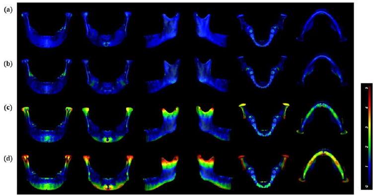
Assessment of MMSP
Statistical analysis
was used to compare the mean differences between the reference plane and sagittal plane measurements.
Results
Model evaluation
Accuracy of landmarks identification
| Landmark | Mean error (mm) | Standard error of the mean (mm) |
| Me | 0.61 | 0.18 |
| B | 0.43 | 0.28 |
| Cor (right) | 0.61 | 0.28 |
| G | 0.65 | 0.19 |
| Pog | 0.66 | 0.42 |
| Conmed (left) | 0.72 | 0.30 |
| MF (left) | 0.77 | 0.26 |
| Sig (left) | 0.79 | 0.22 |
| Gn | 0.79 | 0.39 |
| MF (left) | 0.80 | 0.22 |
| Sig (right) | 0.90 | 0.28 |
| Jlat (right) | 0.94 | 0.15 |
| Cor (left) | 1.17 | 0.35 |
| Consup (right) | 1.18 | 0.28 |
| Go (left) | 1.19 | 0.41 |
| Jmed (left) | 1.21 | 0.35 |
| Jmed (right) | 1.22 | 0.19 |
| Conmed (right) | 1.22 | 0.38 |
| Go (right) | 1.23 | 0.13 |
| RP (right) | 1.29 | 0.38 |
| Consup (left) | 1.30 | 0.24 |
| Conlat (left) | 1.32 | 0.34 |
| F (right) | 1.37 | 0.13 |
| F (left) | 1.39 | 0.21 |
| RP (left) | 1.41 | 0.44 |
| Jlat (left) | 1.45 | 0.27 |
| Conlat (right) | 1.52 | 0.28 |
Plane evaluation
Discussion
| Landmark1 | Landmark2 | Landmark3 | Median (IQR) | Min-Max |
| B | Gn | F | 1.6(1.53-1.92) | 0.59-3.61 |
| B | Me | F | 1.95(1.81-2.34) | 1.05-3.61 |
| B | Pog | F | 1.97(1.75-2.19) | 0.73-5.05 |
| B | G | F | 2.15(1.88-2.81) | 0.68-5.38 |
| B | F | MF | 2.34(2.22-3.11) | 0.69-4.34 |
| .. | .. | .. | .. | .. |
| .. | .. | .. | .. | .. |
| B | G | Me | 7.49(7.24-10.3) | 1.56-19.97 |
| .. | .. | .. | .. | .. |
| .. | .. | .. |
|
.. |
| B | G | MF | 12.57(9.45-16.76) | 1.58-41.71 |
| B | Gn | Me | 12.97(11.6715.82) | 1.34-37.4 |
| G | Me | MF | 17.78(18.4425.32) | 1.81-36.82 |
| B | Pog | Gn | 18.76(17.2525.92) | 0.94-53.46 |
| Pog | Gn | Me | 21.15(18.4933.68) | 1.7-64.04 |
| Landmark | Reference plane(mm) | B-Gn-F(mm) | B-Pog-F(mm) | B-Me-F(mm) | B-G-F(mm) |
| Consup |
|
|
|
|
|
| Conmed |
|
|
|
|
|
| Conlat |
|
|
|
|
|
| Sig |
|
|
|
|
|
| Cor |
|
|
|
|
|
| Go |
|
|
|
|
|
| RP |
|
|
|
|
|
| MF |
|
|
|
|
|
| Jlat |
|
|
|
|
|
| Jmed |
|
|
|
|
|
| F | – |
|
|
|
|
| Mean |
|
|
|
|
|
| Plane | Volume (
|
P value | Similarity index | P value |
| Reference |
|
– |
|
– |
| B-Gn-F |
|
0.671 |
|
** |
| B-Pog-F |
|
0.560 |
|
** |
| B-Me-F |
|
0.438 |
|
** |
| B-G-F |
|
0.537 |
|
** |
| *
|
||||
|
|
||||
segmentation of high-resolution CBCT images in 17 s , a 71.3-fold reduction compared to semiautomated segmentation [17]. Robert et al. created in-house segmentation software that increased the segmentation accuracy to
more complete mandibular boundary can be extracted by iterative upsampling of only the edge points at the end of the model using the multilevel information of the network without affecting most of the foreground pixels.
3D anatomical landmarks reflect the morphological characteristics of the mandible and are the basis of 3D mandibular analysis. Manual landmark localization relies on doctors’ clinical expertise and is tedious [24,25]. The You-Only Look-Once version 3 (YOLOv3) algorithm was applied to 1028 cephalograms to automatically identify 80 cephalometric landmarks with a manual landmark average error of
whole mandibular surface [4]. The ICP was not selected as a reference plane because although both methods use the root-mean-square value, the ICP algorithm calculates the closest distance between the original model and the mirror model, whereas the template mapping method calculates the distance between the original model and the mirror corresponding quasi-landmarks, which has the advantages of more points, intelligence, and good correspondence relationships [9]. When the mandible was heavily asymmetrical, the precision of the ICP algorithm was reduced [4]. Many previous studies used the B-G-Me plane as the MMSP to study the symmetry of mandibles [5, 6]. The results of the present study showed that the AI of the B-G-Me plane was 7.49 (Table 2), which differed significantly from the results obtained for the
Conclusions
Abbreviations
| CBCT | Cone beam computed tomography |
| MMSP | Mandibular midsagittal plane |
| AI | Asymmetry index |
| 3D | Three-dimensional |
| 2D | Two-dimensional |
| CMSP | Craniomaxillary median sagittal plane |
| ICC | Intraclass correlation coefficient |
| ICP | Iterative closest point |
| WPA | Weighted Procrustes analysis |
Supplementary Information
Acknowledgements
Author contributions
Funding
Availability of data and materials
Declarations
Ethics approval and consent to participate
patients/participants provided their written informed consent to participate in this study.
Consent for publication
Competing interests
Author details
Published online: 29 January 2024
References
- Fang JJ, Tu YH, Wong TY, Liu JK, Zhang YX, Leong IF, et al. Evaluation of mandibular contour in patients with significant facial asymmetry. Int J Oral Maxillofac Surg. 2016;45(7):922-31.
- Kwon SM, Hwang JJ, Jung YH, Cho BH, Lee KJ, Hwang CJ, et al. Similarity index for intuitive assessment of three-dimensional facial asymmetry. Sci Rep. 2019;9(1):10959.
- AlHadidi A, Cevidanes LH, Mol A, Ludlow J, Styner M. Comparison of two methods for quantitative assessment of mandibular asymmetry using cone beam computed tomography image volumes. Dentomaxillofac Radiol. 2011;40(6):351-7.
- Fan Y, Zhang Y, Chen G, He W, Song G, Matthews H, et al. Automated assessment of mandibular shape asymmetry in 3-dimensions. Am J Orthod Dentofacial Orthop. 2022;161(5):698-707.
- You KH, Lee KJ, Lee SH, Baik HS. Three-dimensional computed tomography analysis of mandibular morphology in patients with facial asymmetry and mandibular prognathism. Am J Orthod Dentofacial Orthop. 2010;138(5):540.e1-8.
- Kim SJ, Lee KJ, Lee SH, Baik HS. Morphologic relationship between the cranial base and the mandible in patients with facial asymmetry and mandibular prognathism. Am J Orthod Dentofacial Orthop. 2013;144(3):330-40.
- Pittayapat P, Jacobs R, Bornstein MM, Odri GA, Kwon MS, Lambrichts I, et al. A new mandible-specific landmark reference system for threedimensional cephalometry using cone-beam computed tomography. Eur J Orthod. 2016;38(6):563-8.
- Xiong Y, Zhao Y, Yang H, Sun Y, Wang Y. Comparison between interactive closest point and procrustes analysis for determining the median sagittal plane of three-dimensional facial data. J Craniofac Surg. 2016;27(2):441-4.
- Zhu Y, Zhao Y, Wang Y. A review of three-dimensional facial asymmetry analysis methods. Symmetry. 2022;14(7):1414.
- Zhu YJ, Zhao YJ, Zheng SW, Wen AN, Fu XL, Wang Y. A method for constructing three-dimensional face symmetry reference plane based on weighted shape analysis algorithm. Beijing da xue xue bao Yi xue ban
Journal of Peking University Health sciences. 2020;53(1):220-6. - Gao L, Zhang LX, Meng HY, Ren YH, Lai YK, Kobbelt L. PRS-net: planar reflective symmetry detection net for 3d models. IEEE transactions on visualization and computer graphics 2021;27(6):3007-18.
- Verhelst P-J, Matthews H, Verstraete L, Van der Cruyssen F, Mulier D, Croonenborghs TM, et al. Automatic 3D dense phenotyping provides reliable and accurate shape quantification of the human mandible. Scientific Reports 2021;11(1).
- Fan Y, Schneider P, Matthews H, Roberts WE, Xu T, Wei R, et al. 3D assessment of mandibular skeletal effects produced by the Herbst appliance. BMC Oral Health. 2020;20(1):117.
- Moon JH, Hwang HW, Yu Y, Kim MG, Donatelli RE, Lee SJ. How much deep learning is enough for automatic identification to be reliable? Angle Orthod. 2020;90(6):823-30.
- Le C, Deleat-Besson R, Prieto J, Brosset S, Dumont M, Zhang W, et al. Automatic segmentation of mandibular ramus and condyles. Annu Int Conf IEEE Eng Med Biol Soc. 2021Nov:2021:2952-5.
- Qiu B, Guo J, Kraeima J, Glas HH, Borra RJH, Witjes MJH, et al. Automatic segmentation of the mandible from computed tomography scans for 3D virtual surgical planning using the convolutional neural network. Phys Med Biol. 2019;64(17):175020.
- Vinayahalingam S, Berends B, Baan F, Moin DA, van Luijn R, Berge S, et al. Deep learning for automated segmentation of the temporomandibular joint. J Dent. 2023;132: 104475.
- Verhelst PJ, Smolders A, Beznik T, Meewis J, Vandemeulebroucke A, Shaheen E, et al. Layered deep learning for automatic mandibular segmentation in cone-beam computed tomography. J Dent. 2021;114:103786.
- Lo Giudice A, Ronsivalle V, Spampinato C, Leonardi R. Fully automatic segmentation of the mandible based on convolutional neural networks (CNNs). Orthod Craniofac Res. 2021;24 Suppl 2 :100-7.
- Ilesan RR, Beyer M, Kunz C, Thieringer FM. Comparison of artificial intelligence-based applications for mandible segmentation: from established platforms to in-house-developed software. Bioengineering. 2023;10(5):604.
- MinJin Hwang BD, Enrique Dehaerne, Sandip Halder, Young-han Shin. SEMI-PointRend: Improved Semiconductor Wafer Defect Classification and Segmentation as Rendering. arXiv – CS – Computer Vision and Pattern Recognition. 2023.
- Girshick AKYWKHR. PointRend: Image Segmentation as Rendering. arXiv CS – Computer Vision and Pattern Recognition 2019.
- Dong Y, Zhang Y, Hou Y, Tong X, Wu Q, Zhou Z, et al. Damage recognition of road auxiliary facilities based on deep convolution network for segmentation and image region correction. Advances in Civil Engineering. 2022;2022:1-10.
- Blum FMS, Mohlhenrich SC, Raith S, Pankert T, Peters F, Wolf M, et al. Evaluation of an artificial intelligence-based algorithm for automated localization of craniofacial landmarks. Clin Oral Investig. 2023;27(5):2255-65.
- Hwang HW, Park JH, Moon JH, Yu Y, Kim H, Her SB, et al. Automated identification of cephalometric landmarks: part 2-might it be better than human? Angle Orthod. 2020;90(1):69-76.
- Zhang J, Liu M, Wang L, Chen S, Yuan P, Li J, et al. Context-guided fully convolutional networks for joint craniomaxillofacial bone segmentation and landmark digitization. Med Image Anal. 2020;60:101621.
- Dot G, Schouman T, Chang S, Rafflenbeul F, Kerbrat A, Rouch P, et al. Automatic 3-dimensional cephalometric landmarking via deep learning. J Dent Res. 2022;101(11):1380-7.
- Schlicher W, Nielsen I, Huang JC, Maki K, Hatcher DC, Miller AJ. Consistency and precision of landmark identification in three-dimensional cone beam computed tomography scans. Eur J Orthod. 2012;34(3):263-75.
- Dobai A, Markella Z, Vízkelety T, Fouquet C, Rosta A, Barabás J. Landmarkbased midsagittal plane analysis in patients with facial symmetry and asymmetry based on CBCT analysis tomography.Journal of Orofacial Orthopedics / Fortschritte der Kieferorthopädie. 2018;79(6):371-9.
- Gada SK. Assessment of position and bilateral symmetry of occurrence of mental foramen in dentate Asian population. Journal of Clinical and Diagnostic Research. 2014;8(2):203-5
- Findik Y, Yildirim D, Baykul T. Three-dimensional anatomic analysis of the lingula and mandibular foramen. Journal of Craniofacial Surgery. 2014;25(2):607-10.
- Lo Giudice A, Ronsivalle V, Rustico L, Aboulazm K, Isola G, Palazzo G. Evaluation of the accuracy of orthodontic models prototyped with entry-level LCD-based 3D printers: a study using surface-based superimposition and deviation analysis. Clin Oral Investig. 2022;26(1):303-12.
- Lo Giudice A, Ronsivalle V, Santonocito S, Lucchese A, Venezia P, Marzo G, et al. Digital analysis of the occlusal changes and palatal morphology using elastodontic devices. A prospective clinical study including Class II subjects in mixed dentition. Eur J Paediatr Dent. 2022;23(4):275-80
- Green MN, Bloom JM, Kulbersh R. A simple and accurate craniofacial midsagittal plane definition. Am J Orthod Dentofacial Orthop. 2017;152(3):355-63.
- Duran GS, Dindaroglu F, Kutlu P. Hard- and soft-tissue symmetry comparison in patients with class III malocclusion. Am J Orthod Dentofacial Orthop. 2019;155(4):509-22.
- Lo Giudice A, Ronsivalle V, Gastaldi G, Leonardi R. Assessment of the accuracy of imaging software for 3D rendering of the upper airway, usable in orthodontic and craniofacial clinical settings. Prog Orthod. 2022;23(1):22.
Publisher’s Note
Yali Wang and Weizi Wu have contributed equally to this work.
*Correspondence:
Yifan Lin
yflin@hku.hk
Hengguo Zhang
zhanghengguo@ahmu.edu.cn
Jianguang Xu
xujg1982@connect.hku.hk
Full list of author information is available at the end of the articleinterquartile range (25th, 75th percentile); Min minimum; Max maximum;