DOI: https://doi.org/10.1186/s12903-025-05486-5
PMID: https://pubmed.ncbi.nlm.nih.gov/39827102
تاريخ النشر: 2025-01-18
السلوك البيوميكانيكي لإطارات التيتانيوم، الكوبالت-الكروم، الزركونيا، وPEEK في الأطراف الاصطناعية المدعومة بالزرعات: تحليل ديناميكي للعناصر المحدودة
الملخص
الخلفية تؤثر الخصائص الميكانيكية لمواد الإطار بشكل كبير على توزيع الإجهاد ونجاح الأطراف الاصطناعية المدعومة بالزرعات على المدى الطويل. على الرغم من أن التيتانيوم، والكوبالت-الكروم، والزركونيا، والبولي إيثر إيثر كيتون (PEEK) تُستخدم على نطاق واسع، إلا أن أدائها البيوميكانيكي تحت ظروف التحميل الديناميكي لا يزال غير مُستَكشَف بشكل كافٍ. هدفت هذه الدراسة إلى تقييم السلوك البيوميكانيكي لأربعة مواد إطار ذات معاملات يونغ مختلفة باستخدام تحليل الإجهاد الديناميكي بالعناصر المحدودة. الطرق تم استخراج نموذج ثلاثي الأبعاد للفك العلوي الخالي من الأسنان من قاعدة بيانات التصوير المقطعي المحوسب (CT). تم وضع زرعات بمستوى العظم بتصاميم اتصال مخروطي في المناطق الأمامية (الأنفية) والخلفية (الضرس الأول). كانت الزرعات الأمامية متوازية، بينما كانت الزرعات الخلفية مائلة للخلف بزاوية 30 درجة. وفقًا لمادة الإطار، تم تشكيل أربع مجموعات: كوبالت-كروم (Co-Cr)، زركونيا (Zr)، تيتانيوم (Ti)، وبولي إيثر إيثر كيتون (PEEK). لكل مادة إطار، تم إنشاء اثني عشر نموذجًا منفصلًا للتحليل من خلال تطبيق القوة في ثلاث اتجاهات مختلفة. تم استخدام قوى ديناميكية لمحاكاة عملية المضغ. تم قياس وتقييم الإجهادات الرئيسية وإجهاد فون ميس.
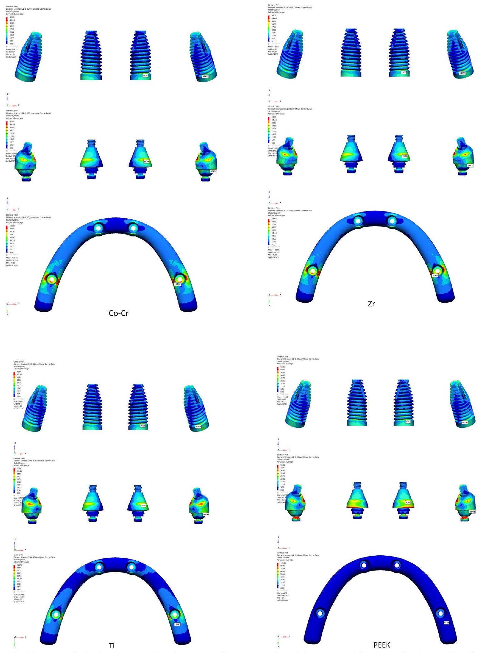
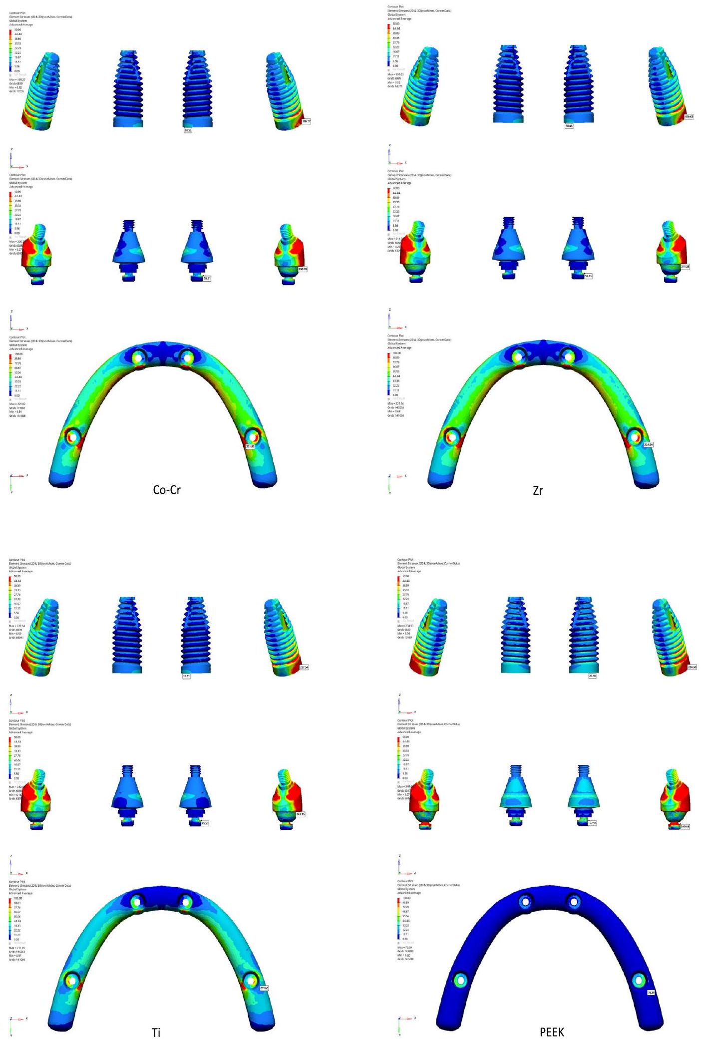
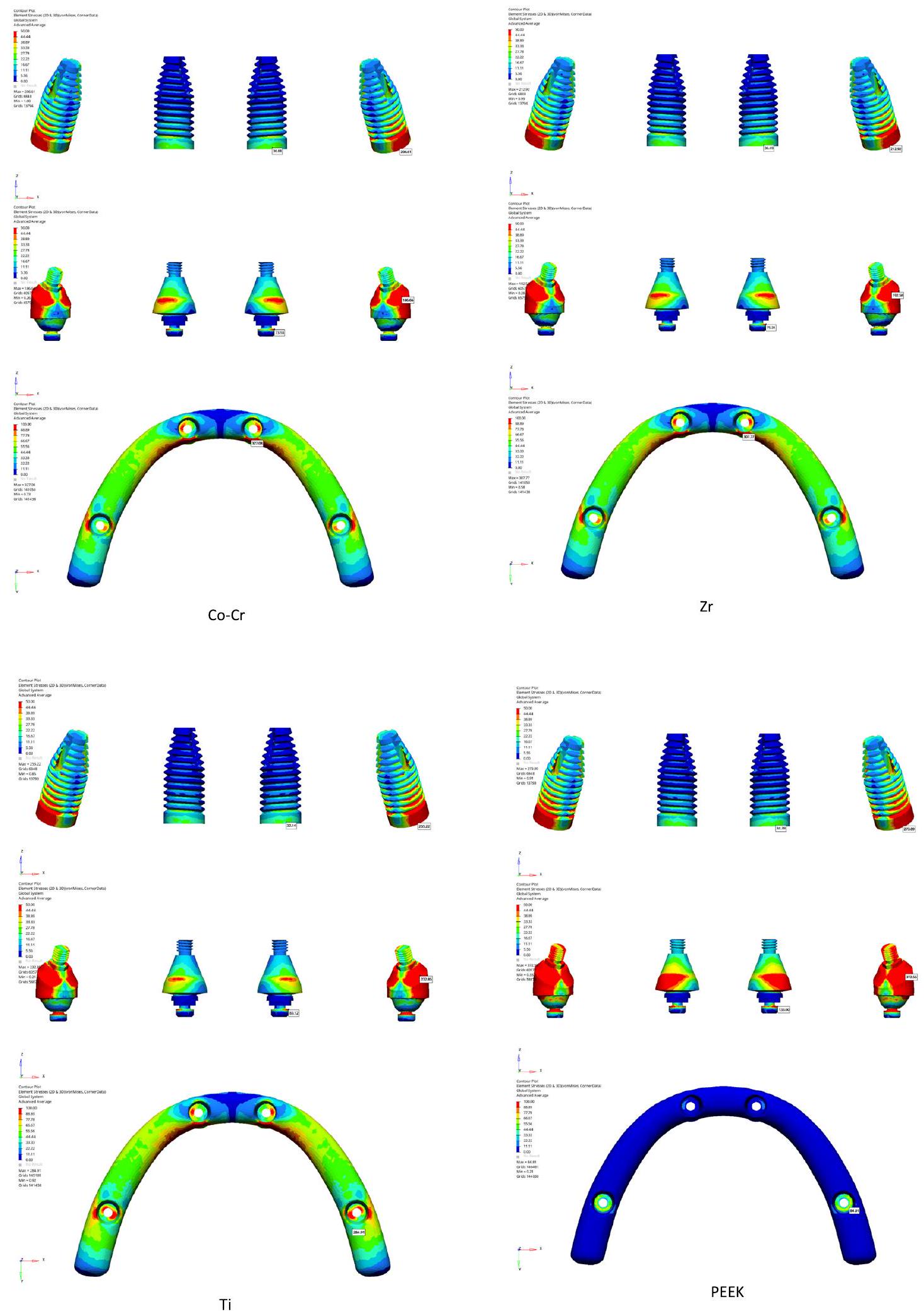
النتائج أظهر إطار PEEK أعلى قيم إجهاد فون ميسيس القصوى (372.55 ميغاباسكال) على الدعامة وأعلى قيم إجهاد رئيسي قصوى.
*المراسلة:
إيريم سوزن يانيك
iremsozen@hacettepe.edu.tr
مقدمة
تعتبر الميزات التشريحية العامل الأكثر أهمية الذي يحد ويعقد علاج الزرع. على المدى الطويل
فقدان الأسنان واستخدام طقم أسنان كامل يسبب فقدان العظم الفكي، مما يجعل جراحة الزرع تحديًا بسبب قربها من الجيب الفكي والقناة الفكية [3]. في مثل هذه الحالات، قد تكون هناك حاجة إلى طرق جراحية معقدة مثل زيادة العظم ورفع الجيب الفكي لإدخال الزرع، مما يزيد من خطر حدوث مضاعفات [4، 5]. تعتبر التعويضات الثابتة على أربعة زرعات خيار علاج يمكن استخدامه بدلاً من هذه الطرق الجراحية المعقدة [6].
يجب أن يكون الإطار لدعامة الأسنان الثابتة المدعومة بالزرعات متوافقًا حيويًا وخفيف الوزن ومقاومًا للضغوط التي قد تتطور أثناء الاستخدام. قد يكون لمادة الإطار تأثير كبير على نقل الإجهاد إلى نظام دعم الزرعة ومنطقة العظم المحيط بالزرعة. التيتانيوم (Ti) وسبائك الكوبالت والكروم (
إن التأثير البيوميكانيكي للأطر البوليمرية وغير البوليمرية على توزيع الإجهاد أمر حاسم للنجاح على المدى الطويل. تعتبر تحليل العناصر المحدودة (FEA) طريقة مفيدة لفحص السلوكيات البيوميكانيكية للأشكال المعقدة كخطوة أولى، وقد تكشف عن معلومات لم تتوفر بعد سريرياً. تتضمن طريقة FEA كل من طرق التحميل الثابتة (غير المتغيرة) والديناميكية (المتغيرة مع الزمن). خلال التحميل الثابت، يتم تطبيق قوة من مقدار معين من اتجاه واحد، بينما يشير التحميل الديناميكي إلى حمل يتغير مع مرور الوقت استجابةً لكمية واتجاه القوة الخارجية. يتسبب التحميل الديناميكي في مستوى إجهاد أعلى من التحميل الثابت.
تم إجراء أبحاث محدودة على الخصائص البيوميكانيكية للمواد الجديدة تحت الضغط الديناميكي. سعت الدراسة الحالية إلى تقييم الخصائص البيوميكانيكية لمواد التيتانيوم، والكروم-كوبالت، والزركونيوم، وبيوليثير إيثر كيتون (PEEK) المستخدمة في أربعة أطقم ثابتة مدعومة بالزرعات.
تحليل الإجهاد. كانت الفرضية الصفرية تنص على أنه لا يوجد تباين كبير في توزيع الإجهادات في الهياكل.
طرق
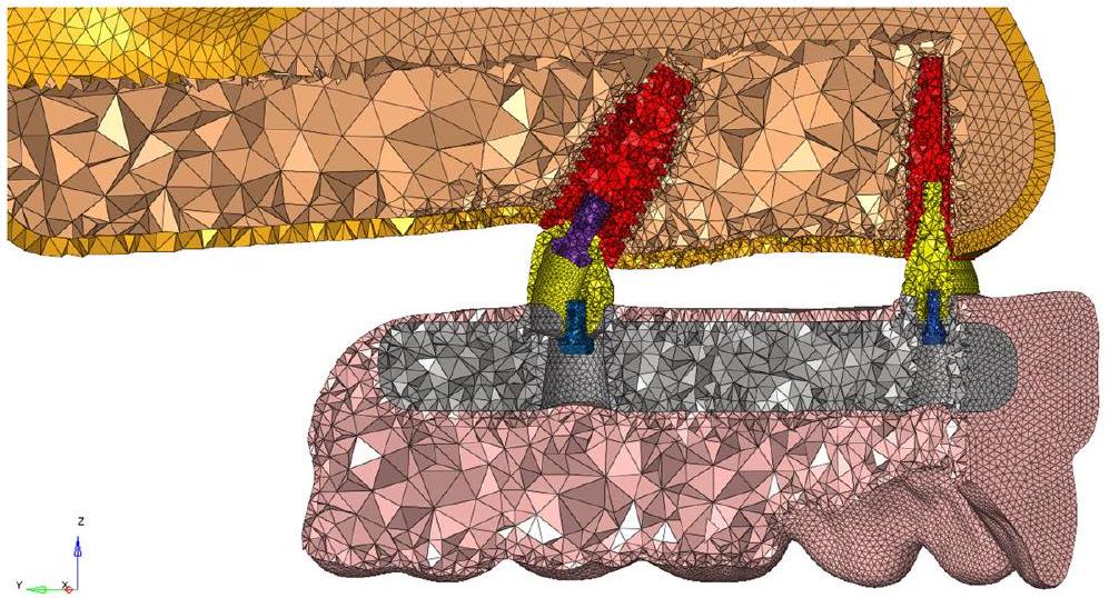
تم إعادة بناء بيانات التصوير المقطعي بسمك مقطع يبلغ 0.1 مم. تم نقل بيانات التصوير المقطعي التي تم الحصول عليها من إعادة البناء إلى برنامج 3DSlicer بتنسيق DICOM (.dcm). تم تقسيم بيانات التصوير المقطعي (CT) بتنسيق DICOM باستخدام قيم هونسفيلد المناسبة في برنامج 3DSlicer وتحويلها إلى نموذج ثلاثي الأبعاد من خلال التقسيم. تم نقل النموذج بتنسيق STL. تم ترتيب الهيكل الشبكي ثلاثي الأبعاد وتحويله رياضيًا إلى هيكل شبكة صلبة مناسب، وتم إنشاء نماذج تحليل العناصر المحدودة ثلاثية الأبعاد، وتم إجراء تحليل إجهاد العناصر المحدودة على محطات عمل HP المزودة بمعالجات INTEL Xeon E-2286 التي تعمل بتردد 2.40 جيجاهرتز وذاكرة ECC سعة 64 جيجابايت. تم تنفيذ أنشطة الهندسة العكسية وCAD ثلاثية الأبعاد باستخدام برنامج ALTAIR Evolve، وتم تكييف النماذج الصلبة مع بيئة التحليل وتم إجراء تحسين الشبكات باستخدام برنامج ALTAIR Hypermesh؛ تم استخدام حل ALTAIR Optistruct القائم على Nastran لحل نماذج العناصر المحدودة. تم تحميل النموذج ثلاثي الأبعاد إلى برنامج ALTAIR Evolve، حيث تم إنشاء هندسة قشرية مناسبة للفك العلوي الضامر. تم ضبط سمك العظم القشري ليكون 2 مم. تم إنشاء العظم الإسفنجي باستخدام السطح الداخلي للعظم القشري mandibular ثلاثي الأبعاد كمرجع. تم استخدام زرع مستوى العظم (زرع NobelParallel Conical Connection TiUltra، Nobel Biocare، سويسرا) بتصميم اتصال مخروطي في الدراسة. تم محاكاة الزرع، والدعامة متعددة الوحدات، والبراغي المستخدمة في الدراسة جميعها باستخدام برنامج ALTAIR Evolve. تم إنشاء القطع التعويضية (الهيكل الفرعي والبدلة) باستخدام برنامج ALTAIR Evolve. تم اختيار المعلمات التالية للزرع: قطر 4.3 مم، طول 11.50 مم، ارتفاع مائل 0.2 مم، ارتفاع حافة 0.5 مم، وزاوية مائلة من
في هذه الدراسة، تم إجراء اختبار تقارب الشبكة لضمان موثوقية ودقة نموذج العناصر المحدودة المستخدم في التحليل البيوميكانيكي. كان الهدف الأساسي هو تحديد كثافة شبكة مناسبة توازن بين الكفاءة الحاسوبية ودقة الحل، مع تحقيق خطأ أقل من
تم إنشاء سلسلة من شبكات العناصر المحدودة بأحجام عناصر متغيرة، تتراوح من الشبكات الخشنة إلى الشبكات الدقيقة. تم تحليل كل شبكة تحت نفس ظروف التحميل والحدود لضمان الاتساق في المقارنة. تم اختيار ضغوط فون ميس للزرعات والضغوط الرئيسية للعظم حول الزرعة كمعايير تقييم. هذه المعلمات حاسمة لتقييم السلوك البيوميكانيكي للنظام. تم مقارنة النتائج من تحسينات الشبكة المتعاقبة لملاحظة التغيير في معايير التقييم. تم حساب الخطأ النسبي بين نتائج الشبكات المتعاقبة باستخدام الصيغة:
| حجم الشبكة (مم) | الضغط المقدر (ميغاباسكال) | الخطأ النسبي (%) |
| 0.5 | 92.13 | – |
| 0.3 | 100.27 | 8.84 |
| 0.2 | 105.04 | 4.75 |
| 0.1 | 108.12 | 2.93 |
| حجم الشبكة (مم) | الضغط المقدر (ميغاباسكال) | الخطأ النسبي (%) |
| 0.5 | 22.96 | – |
| 0.3 | 25.69 | 11.89 |
| 0.2 | 27.12 | 5.57 |
| 0.1 | 27.88 | 2.80 |
تم استخدام كثافة الشبكة المعتمدة هذه للتحليلات اللاحقة لتوفير نتائج موثوقة. يتم تقديم العدد الإجمالي للعناصر والعقد للنموذج الذي تم إنشاؤه في ضوء اختبار تقارب الشبكة في الجدول 3.
أثناء إعداد النموذج، تم استخدام شبكات ثنائية الأبعاد مثلثية وثلاثية الأبعاد هرمية. تعتبر هذه الأنواع من الشبكات أكثر ملاءمة للنماذج العضوية مثل العظم بسبب قدرتها على التقاط الهندسات المعقدة والأسطح المنحنية بشكل أفضل. في جميع النماذج، تم التحقق من جودة الشبكة
للأشكال المثلثية مع انحراف
تم إنشاء نماذج رياضية عن طريق تقسيم النماذج الهندسية إلى أقسام أساسية وصغيرة تعرف بالشبكات. بعد الانتهاء من عملية النمذجة في برنامج ALTAIR Evolve، تم بناء النماذج رياضيًا باستخدام برنامج ALTAIR Hypermesh و
| النموذج | 116,231 |
| إجمالي عدد العناصر | 433,821 |
| المادة | معامل المرونة [ميغاباسكال] | نسبة بواسون |
| العظم القشري | 14,000 | 0.3 |
| العظم الإسفنجي | 1400 | 0.3 |
| Co-Cr | 218,000 | 0.33 |
| Zr | 200,000 | 0.31 |
| Ti | 110,000 | 0.35 |
| PEEK | 4100 | 0.3 |
تم إعدادها للتحليل. لإجراء الدراسات، تم تحميل النماذج التي تم إنشاؤها في برنامج ALTAIR Hypermesh إلى أداة تحليل ALTAIR Optistruct بتنسيق .fem. تم أخذ معامل بواسون ومعامل المرونة لكل مادة مستخدمة في هذه الدراسة من الأدبيات. (الجدول 4) [10]. يتم تحديد خصائص المواد للنموذج الذي تم تحليله رقميًا. تم تطوير أربعة أطر متميزة: الكوبالت والكروم (
المرحلة 3. تم تطبيق القوة بين
المرحلة 4. تم تطبيق القوة بين 0.260-0.300 ثانية من الفم إلى الحنك بزاوية
المرحلة 5. لم يتم تطبيق أي قوة بين 0.3000.875 ثانية.
لتنفيذ التحليلات والحصول على نتائج دقيقة في النماذج الرياضية المطورة، يجب أن يتم تحديد العلاقات
النتائج
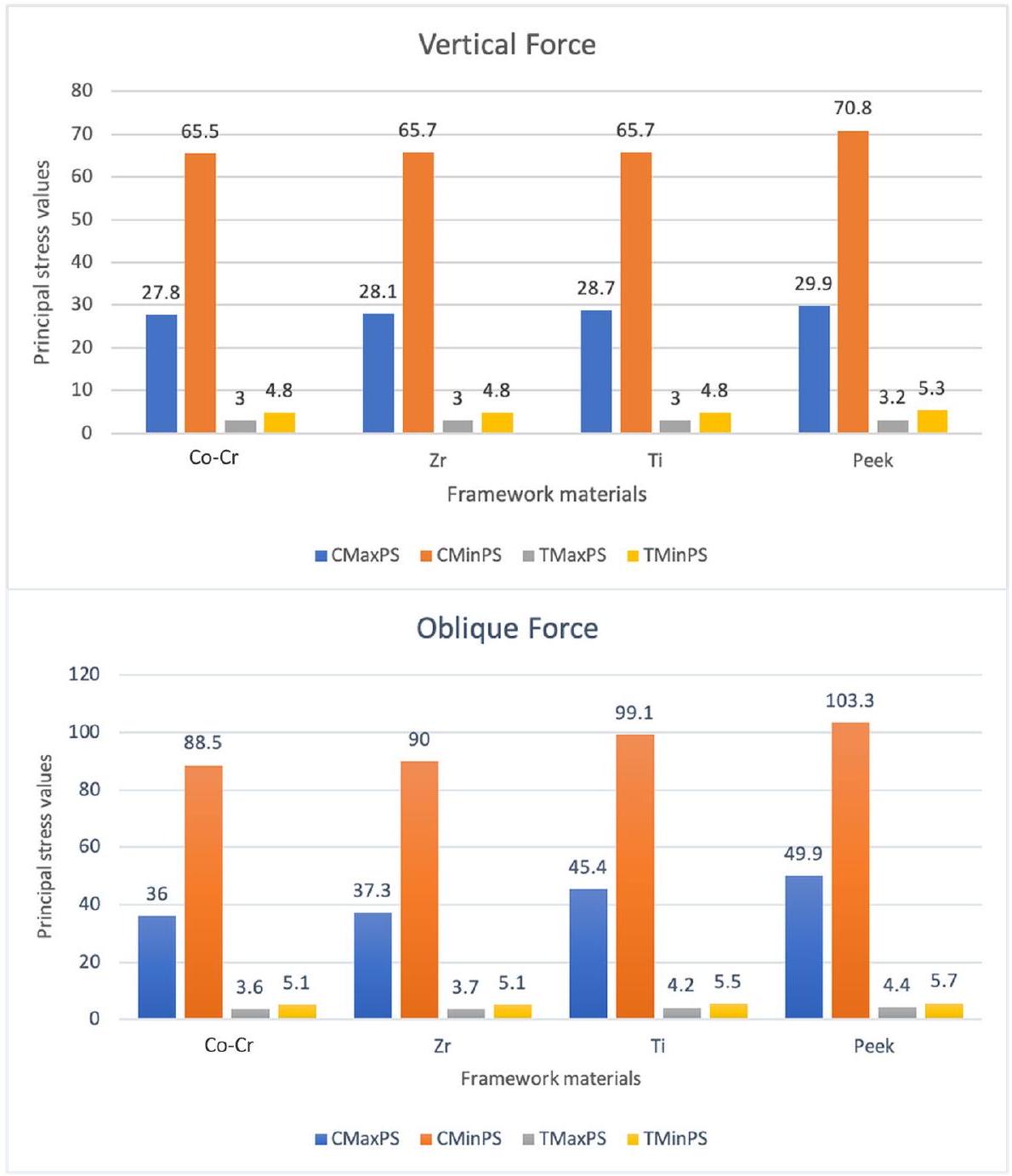
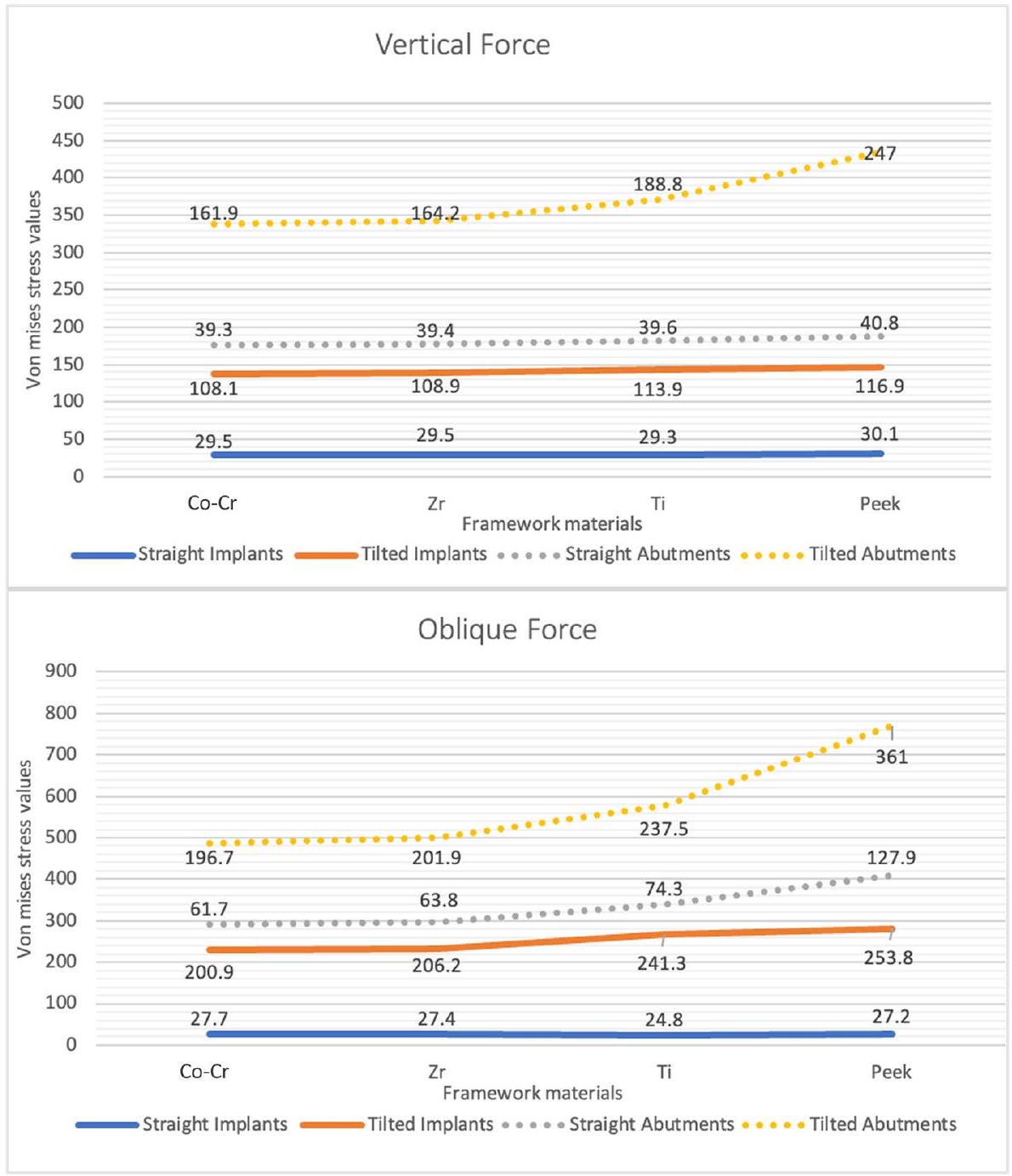
أظهرت قيم ضغط فون ميس تحت القوة العمودية أن الدعائم المائلة في إطار PEEK وصلت إلى أعلى مستوى ضغط قدره 247 ميغاباسكال، بينما أظهرت الزرعات المستقيمة أدنى قيم ضغط عبر جميع مواد الإطار، تتراوح بين 29.5 ميغاباسكال إلى 30.1 ميغاباسكال. تحت القوة المائلة، أظهرت الدعائم المائلة لإطار PEEK أيضًا أعلى قيم ضغط، حيث بلغت ذروتها عند
تحت الضغوط العمودية والمائلة، كانت قيم ضغط فون ميس في الأطر الأعلى لـ
المناقشة
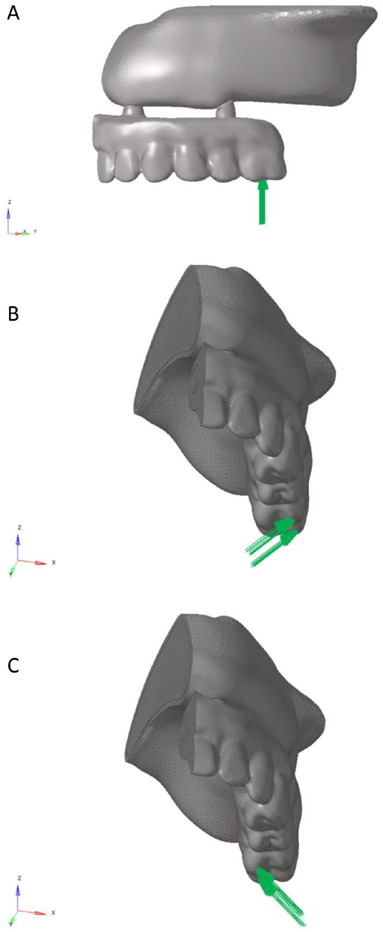
| مرحلة التحميل | وقت التحميل (ث) | الاتجاهات | الموضع | قوة التحميل (ن) |
| 1 | 0.000~0.130 | |||
| 2 |
|
عمودي على المستوى الإطباقي | فوق التكتلات الخدّية والحنكية | 150 |
| 3 |
|
من الحنك إلى الخد مع
|
فوق المنحدر الحنكي للتكتلات الخدّية | 150 |
| 4 | 0.260~0.300 | من الخد إلى الحنك مع
|
فوق المنحدر الخدي للتكتلات الحنكية | 150 |
| 5 |
|
المنطقة الخلفية القريبة من جانب تطبيق الحمل للعظم القشري والاسفنجي.
استخدم سيراندوني وآخرون [10] تحليل العناصر المحدودة لتقييم الخصائص البيوميكانيكية لستة إطارات مختلفة (التيتانيوم، الكوبالت-الكروم، الزركونيا، بولي إيثر إيثر كيتون، بولي إيثر إيثر كيتون المدعم بألياف الكربون، وبولي ميثيل ميثاكريلات) في الأطراف الثابتة المدعومة بالغرسات السنية. وقد وُجد أن المواد المرنة (بولي إيثر إيثر كيتون وبولي ميثيل ميثاكريلات) تسبب زيادة في الإجهاد الشد في العظم. أنتجت الإطارات الأكثر صلابة أفضل النتائج.
تم العثور على نتائج مشابهة في دراسة مخبرية قيمت الخصائص البيوميكانيكية للإطارات المعدنية مع معاملات يونغ مختلفة [16].
تمثل مستويات الإجهاد الرئيسية كلاً من الإجهاد الشد والضغط في العظم [10]. وقد تم الإبلاغ عن أن الحدود الفسيولوجية للإجهاد الشد والضغط للعظم القشري هي 130 ميجا باسكال و190 ميجا باسكال، على التوالي [18]. في الدراسة الحالية، كانت مستويات الإجهاد في كل مجموعة ضمن الحدود الفسيولوجية للعظم القشري. من ناحية أخرى، قد تؤدي المستويات الأكبر من 5 ميجا باسكال إلى
تحميل زائد في العظم الترابيكولار، مما يؤدي إلى امتصاص العظم [19]. تحت الضغوط العمودية، تجاوز إطار PEEK فقط الحد الحرج؛ ومع ذلك، تحت القوى المائلة، تجاوزت جميع المجموعات الحد. يتسبب التحميل الديناميكي في مستويات إجهاد أعلى من التحميل الثابت. وقد قيمت دراسة سابقة السلوك الثابت والديناميكي للغرسات السنية، وتم الإبلاغ عن أن قيم إجهاد فون ميسيس لمكونات الغرسة والأطراف تكون أكبر تحت التحميل الديناميكي [20]. عند تحليل قيم الإجهاد المستمدة من هذه الدراسة، يجب أن تضع في اعتبارك أن جميع الاختبارات تمت تحت التحميل الديناميكي.
تشير إزاحة عنصر ما إلى مدى بعده عن نقطة مرجعية معينة؛ في تحليل العناصر المحدودة، غالبًا ما يكون هذا هو أصل نظام إحداثيات النموذج. قد تقلل الإطارات الصلبة من الإجهاد على الغرسة،
تتمثل قيود دراسات تحليل العناصر المحدودة التي تحقق في السلوك الميكانيكي للغرسات والأنسجة المحيطة في أن أفضل الظروف قد لا تمثل بدقة التطبيقات السريرية الفعلية. افترضنا أن جميع المواد متجانسة، متساوية الخواص، ومرنة خطيًا. بالإضافة إلى ذلك، كان من المتوقع أن تكون الغرسات متكاملة تمامًا مع العظم. ومع ذلك، قد تكون هذه النتائج مفيدة في فهم الواقع
العملي، على الرغم من الحاجة إلى مزيد من الدراسات الحية والمخبرية لتأكيدها.
الاستنتاجات
| CAD/CAM | التصميم بمساعدة الكمبيوتر/التصنيع بمساعدة الكمبيوتر |
| Co-Cr | الكوبالت-الكروم |
| CMaxPS | أقصى إجهاد رئيسي في العظم القشري |
| CMinPS | الحد الأدنى من الإجهاد الرئيسي في العظم القشري |
| CT | التصوير المقطعي المحوسب |
| FEA | تحليل العناصر المحدودة |
| مم | ميليمتر |
| ميجا باسكال | ميجا باسكال |
| ن | نيوتن |
| PEEK | بولي إيثر إيثر كيتون |
| STL | لغة التقطيع القياسية |
TMinPS الحد الأدنى من الإجهاد الرئيسي في العظم الترابيكولار
Ti التيتانيوم
Zr الزركونيا
2D بعدين
3D ثلاثي الأبعاد
الشكر والتقدير
مساهمات المؤلفين
التمويل
توفر البيانات
الإعلانات
موافقة الأخلاقيات والموافقة على المشاركة
الموافقة على النشر
المصالح المتنافسة
تم النشر على الإنترنت: 18 يناير 2025
References
- Agliardi E, Clerico M, Ciancio P, Massironi D. Immediate loading of full-arch fixed prostheses supported by axial and tilted implants for the treatment of edentulous atrophic mandibles. Quintessence Int. 2010;41:285-93.
- Agliardi E, Panigatti S, Clerico M, Villa C, Malò P. Immediate rehabilitation of the edentulous jaws with full fixed prostheses supported by four implants: interim results of a single cohort prospective study. Clin Oral Implants Res. 2010;21:459-65.
- Misch CE. Contemporary implant dentistry. 3rd ed. St Louis: Mosby; 2007.
- Drago C. Ratios of cantilever lengths and anterior-posterior spreads of definitive hybrid full-arch, screw-retained prostheses: results of a clinical study. J Prosthodont. 2018;27:402-8.
- Patras M, Martin W. Simplified custom impression post for implant-supported restorations. J Prosthet Dent. 2016;115:556-9.
- Sadowsky SJ. The implant-supported prosthesis for the edentulous arch: design considerations. J Prosthet Dent. 1997;78:28-33.
- Verma S, Sharma N, Kango S, Sharma S. Developments of PEEK (Polyetheretherketone) as a biomedical material: a focused review. Eur Polymer J. 2021;147:110295.
- Maló P, de Araújo NM, Rangert B. Short implants placed one-stage in maxillae and mandibles: a retrospective clinical study with 1 to 9 years of follow-up. Clin Implant Dent Relat Res. 2007;9:15-21.
- Villefort RF, Tribst JPM, Dal Piva AMdO, Borges AL, Binda NC, Ferreira CEdA, et al. Stress distribution on different bar materials in implant-retained palatal obturator. PLoS One. 2020;15:e0241589. https://doi.org/10.1371/ journal.pone.0241589.
- Sirandoni D, Leal E, Weber B, Noritomi PY, Fuentes R, Borie E. Effect of different framework materials in implant-supported fixed Mandibular prostheses: a finite element analysis. Int J Oral Maxillofac Implants. 2019;34:107-14.
- Hulterström M, Nilsson U. Cobalt-chromium as a framework material in implant-supported fixed prostheses: a preliminary report. Int J Oral Maxillofac Implants. 1991;6:475-80.
- Akyuz E, Braun JT, Brown NA, Bachus KN. Static versus dynamic loading in the mechanical modulation of vertebral growth. Spine. 2006;31:952-8.
- Borie E, Orsi IA, de Araujo CP. The influence of the connection, length and diameter of an implant on bone biomechanics. Acta Odontol Scand. 2015;73:321-9.
- Qian L, Todo M, Matsushita Y, Koyano K. Effects of implant diameter, insertion depth, and loading angle on stress/strain fields in implant/ jawbone systems: finite element analysis. Int J Oral Maxillofac Implants. 2009;24:877-86.
- Lee K-S, Shin S-W, Lee S-P, Kim J-E, Kim J-H, Lee J-Y, et al. Comparative evaluation of a four-implant-supported polyetherketoneketone framework prosthesis: a three-dimensional finite element analysis based on cone beam computed tomography and computer-aided design. Int J Prosthodont. 2017;30:581-5.
- Bacchi A, Consani RLX, Mesquita MF, Dos Santos MBF. Effect of framework material and vertical misfit on stress distribution in implant-supported partial prosthesis under load application: 3-D finite element analysis. Acta Odontol Scand. 2013;71:1243-9.
- Yu W, Li X, Ma X, Xu X. Biomechanical analysis of inclined and cantilever design with different implant framework materials in mandibular com-plete-arch implant restorations. J Prosthet Dent. 2022;127:783.e1-e10.
- Bozkaya D, Muftu S, Muftu A. Evaluation of load transfer characteristics of five different implants in compact bone at different load levels by finite elements analysis. J Prosthet Dent. 2004;92:523-30.
- Baggi L, Cappelloni I, Di Girolamo M, Maceri F, Vairo G. The influence of implant diameter and length on stress distribution of osseointegrated implants related to crestal bone geometry: a three-dimensional finite element analysis. J Prosthet Dent. 2008;100:422-31.
- Kayabaşı O, Yüzbasıoğlu E, Erzincanlı F. Static, dynamic and fatigue behaviors of dental implant using finite element method. Adv Eng Softw. 2006;37:649-58.
- Bhering CLB, Mesquita MF, Kemmoku DT, Noritomi PY, Consani RLX, Barão VAR. Comparison between all-on-four and all-on-six treatment concepts and framework material on stress distribution in atrophic maxilla: A prototyping guided 3D-FEA study. Mater Sci Eng C Mater Biol Appl. 2016;69:715-25.
- Chen X, Mao B, Zhu Z, Yu J, Lu Y, Zhang Q, et al. A three-dimensional finite element analysis of mechanical function for 4 removable partial denture designs with 3 framework materials:
alloy and PEEK. Sci Rep. 2019;9:13975.
ملاحظة الناشر
DOI: https://doi.org/10.1186/s12903-025-05486-5
PMID: https://pubmed.ncbi.nlm.nih.gov/39827102
Publication Date: 2025-01-18
Biomechanical behavior of titanium, cobalt-chromium, zirconia, and PEEK frameworks in implant-supported prostheses: a dynamic finite element analysis
Abstract
Background The mechanical properties of framework materials significantly influence stress distribution and the long-term success of implant-supported prostheses. Although titanium, cobalt-chromium, zirconia, and polyether ether ketone (PEEK) are widely used, their biomechanical performance under dynamic loading conditions remains insufficiently investigated. This study aimed to evaluate the biomechanical behavior of four framework materials with different Young’s modulus using dynamic finite element stress analysis. Methods A 3D edentulous maxillary model was extracted from a computer tomography (CT) database. Bone level implants with conical connection designs were placed in the anterior (canine) and posterior (first molar) areas. Anterior implants were parallel, yet posterior implants were inclined distally by 30 degrees. According to the framework material, four groups were formed: cobalt-chromium (Co-Cr), zirconia (Zr), titanium (Ti), and polyether ether ketone (PEEK). For each framework material, twelve separate models of analysis were created by applying force in three different orientations. Dynamic forces were employed to replicate the chewing process. Principal and von Mises stresses were measured and evaluated.
Results The PEEK framework exhibited the highest maximum von Mises stress values ( 372.55 MPa ) on the abutment and the highest maximum principle stress values
*Correspondence:
Irem Sozen Yanik
iremsozen@hacettepe.edu.tr
Introduction
Anatomical features are the single most important factor limiting and complicating implant therapy. Long-term
edentulism and using a full denture cause alveolar bone loss, which makes implant surgery challenging owing to its closeness to the maxillary sinus and the mandibular canal [3]. In such situations, complex surgical methods like as bone augmentation and maxillary sinus elevation may be necessary for implant insertion, thereby increasing the risk of problems [4, 5]. Fixed prosthesis on four implants is a therapy option that can be used instead of these complex surgical methods [6].
The framework for implant-supported fixed prosthesis should be biocompatible, lightweight, and resistant to pressures that may develop during use. The framework material may have a significant impact in stress transfer to the implant-support system and peri-implant bone area. Titanium (Ti) and a cobalt-chromium (
The biomechanical impact of polymeric and non-polymeric frameworks on stress distribution is crucial to long-term success. Finite element analysis (FEA) is a useful method for examining the biomechanical behaviors of complicated geometries as a first step, and it may reveal information that is not yet clinically available [10]. The FEA approach incorporates both static (non-changing) and dynamic (time-varying) loading methods. During static loading, a force of one magnitude is delivered from one direction [11], dynamic loading refers to a load that varies over time in response to the quantity and direction of an external force. Dynamic loading causes a higher stress level than static loading [12].
Limited research has been undertaken on the biomechanical characteristics of new framework materials under dynamic stress [13, 14]. The present study sought to assess the biomechanical properties of titanium, chro-mium-cobalt, zirconium, and polyether ether ketone (PEEK) materials employed in four implant-supported whole arch fixed prostheses using dynamic finite element
stress analysis. The null hypothesis stated that there was no significant variation in the stress distribution of frameworks.
Methods
The tomography data was reconstructed with a section thickness of 0.1 mm . The tomography data acquired from reconstruction were transmitted to 3DSlicer software in DICOM (.dcm) format. The computer tomography (CT) data in DICOM format was segmented using the proper Hounsfield values in 3DSlicer software and transformed into a three-dimensional model by segmentation. The model was transferred in STL format. The three-dimensional network structure was arranged and mathematically transformed into a suitable solid network structure, three-dimensional finite element analysis models were created, and finite element stress analysis was performed on HP workstations equipped with INTEL Xeon E-2286 processors running at 2.40 GHz and 64 GB ECC memory. Reverse engineering and three-dimensional CAD activities were carried out with ALTAIR Evolve software, solid models were adapted to the analysis environment and optimisedmeshing was performed with ALTAIR Hypermesh software; Nastran-based ALTAIR Optistruct implicit solver was used to solve the finite element models. The three-dimensional model was uploaded to the ALTAIR Evolve program, where the proper atrophic maxilla cortical geometry was created. The cortical bone thickness was adjusted to 2 mm . Trabecular bone was generated by using the inner surface of the three-dimensional mandibular cortical bone as a reference. Bone level implant (NobelParallel Conical Connection TiUltra implant, Nobel Biocare, Switzerland) with a conical connection design was used in the study. The implant, multi-unit abutment, and screws utilized in the study were all simulated using ALTAIR Evolve software. Prosthetic pieces (substructure and prosthesis) were created using ALTAIR Evolve program. The following implant parameters were selected: a diameter of 4.3 mm , a length of 11.50 mm , a bevel height of 0.2 mm , a rim height of 0.5 mm , a bevel angle of
In this study, a mesh convergence test was conducted to ensure the reliability and accuracy of the finite element model used in the biomechanical analysis. The primary objective was to determine an appropriate mesh density that balances computational efficiency with solution accuracy, achieving an error below
A series of finite element meshes with varying element sizes were generated, ranging from coarse to fine meshes. Each mesh was analyzed under the same loading and boundary conditions to ensure consistency in comparison. Von Mises stresses of the implants and principal stresses of the bone around the implant were selected as the evaluation metrics. These parameters are critical for assessing the biomechanical behavior of the system. The results from successive mesh refinements were compared to observe the change in the evaluation metrics. The relative error between successive mesh results was calculated using the formula:
| Mesh Size (mm) | Estimated Stress (MPa) | Relative Error (%) |
| 0.5 | 92.13 | – |
| 0.3 | 100.27 | 8.84 |
| 0.2 | 105.04 | 4.75 |
| 0.1 | 108.12 | 2.93 |
| Mesh Size (mm) | Estimated Stress (MPa) | Relative Error (%) |
| 0.5 | 22.96 | – |
| 0.3 | 25.69 | 11.89 |
| 0.2 | 27.12 | 5.57 |
| 0.1 | 27.88 | 2.80 |
This validated mesh density was used for subsequent analyses to provide reliable results. The total number of elements and nodes of the model created under the light of the mesh convergence test is presented in the Table 3.
During the preparation of the model, triangular 2D and tetrahedral 3D meshes were employed. These mesh types are considered more appropriate for organic models such as bone due to their capability to better capture complex geometries and curved surfaces. In all models, mesh
quality was checked for triangles with skewness
Mathematical models were created by splitting geometric models into basic, tiny sections known as meshes. After the modeling process was finished in ALTAIR Evolve software, the models were mathematically constructed using ALTAIR Hypermesh software and
| Model | 116,231 |
| Total # of Elements | 433,821 |
| Material | Elastic Modulus [MPa] | Poisson Ratio |
| Cortical bone | 14,000 | 0.3 |
| Trabecular bone | 1400 | 0.3 |
| Co-Cr | 218,000 | 0.33 |
| Zr | 200,000 | 0.31 |
| Ti | 110,000 | 0.35 |
| PEEK | 4100 | 0.3 |
prepared for analysis. To conduct the studies, the models created in the ALTAIR Hypermesh software were uploaded to the ALTAIR Optistruct analysis tool in.fem format. The Poisson coefficient and modulus of elasticity for each material utilized in this investigation were taken from the literature. (Table 4) [10]. The material characteristics of the analyzed model are specified numerically. Four distinct frameworks were developed: cobalt-chromium (
Stage 3. The force between
Stage 4. Force between 0.260-0.300 s was applied from buccal to palatinal at a
Stage 5. No force was applied between 0.3000.875 s .
To execute analyses and acquire accurate findings in the mathematical models developed, the surface
Results
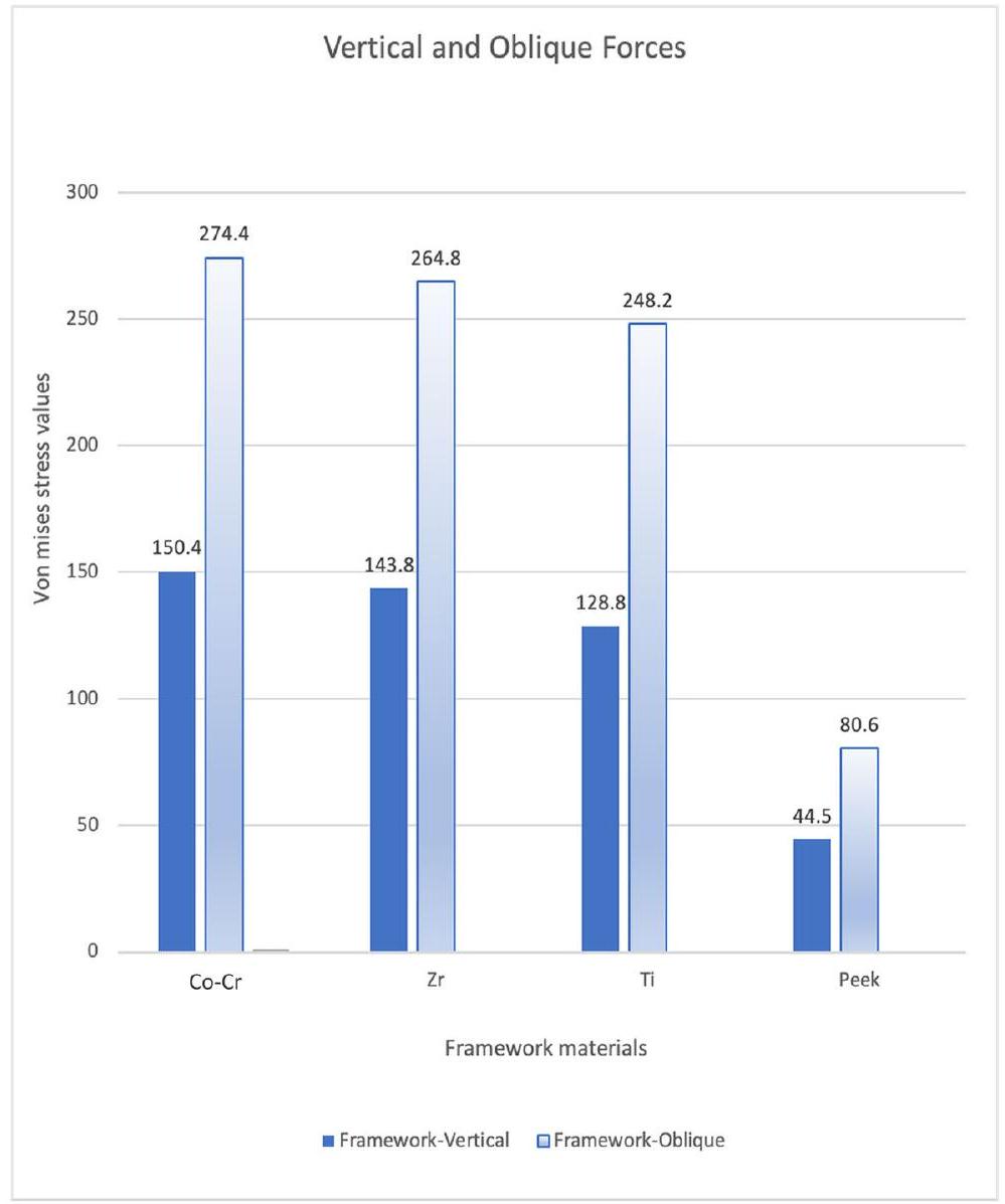
The von Mises stress values under vertical force showed that tilted abutments in the PEEK framework reached the highest stress level of 247 MPa , while straight implants exhibited the lowest stress values across all framework materials, ranging from 29.5 MPa to 30.1 MPa . Under oblique force, tilted abutments for the PEEK framework also demonstrated the highest stress values, peaking at
Under vertical and oblique pressures, the von Mises stress values in the frames were highest for
Discussion
| Loading Stage | Loading Time (s) | Directions | Position | Loading Force(N) |
| 1 | 0.000~0.130 | |||
| 2 |
|
Perpendicular to the occlusal plane | Over the buccal and palatinal tubercles | 150 |
| 3 |
|
From the palatinal to buccal with
|
Over the palatinal slope of the buccal tubercles | 150 |
| 4 | 0.260~0.300 | From the buccal to palatinal with
|
over the buccal slope of the palatinal tubercles | 150 |
| 5 |
|
posterior area which is near the load application side for cortical and cancellous bone.
Sirandoni et al. [10] used finite element analysis to evaluate the biomechanical properties of six different frameworks (titanium, cobalt-chromium, zirconia, polyether ether ketone, carbon fiber-reinforced polyether ether ketone, and polymethyl methacrylate) in implant-supported fixed mandibular prostheses. It has been found that resilient materials (polyether ether ketone and polymethyl methacrylate) cause increased tensile stress in bone. Stiffer frames produced the most positive results.
Similar findings were found in an in vitro investigation that evaluated the biomechanical characteristics of metal frameworks with various Young’s modulus [16].
Principal stress levels represent both tensile and compressive stress in bone [10]. It was reported that the physiological limits of tensile and compressive stresses for the cortical bone are 130 MPa and 190 MPa , respectively [18]. In the present study, each group had stress levels within physiological limits for cortical bone. On the other hand, levels larger than 5 MPa may produce an
overload in the trabecular bone, leading to bone resorption [19]. Under vertical stresses, only the PEEK framework surpassed the critical limit; however, under oblique forces, all groups exceeded the limit. Dynamic loading causes higher stress levels than static loading. A prior study evaluated static and dynamic behaviors of dental implants, and it was reported that von Mises stress values of implant and prosthetic component are greater under dynamic loading [20]. When analyzing the stress values derived from this study, keep in mind that all tests were done under dynamic loading.
The displacement of an item indicates how far it is from a specific reference point; in FEA, this is frequently the origin of the model’s coordinate system. Rigid frames may reduce stress on the implant,
The limitation of FEA studies that investigate the mechanical behavior of implants and surrounding tissue is that the best circumstances may not accurately represent actual clinical applications. We assumed that all materials were homogeneous, isotropic, and linearly elastic. In addition, implants were expected to be completely osseointegrated. Nonetheless, these findings might be useful in comprehending real-world
settings, albeit more in vivo and in vitro investigations are needed to corroborate them.
Conclusions
| CAD/CAM | Computer-aided design/computer-aided manufacture |
| Co-Cr | Cobalt-chromium |
| CMaxPS | Maximum principal stress in the cortical bone |
| CMinPS | Minimum principal stress in the cortical bone |
| CT | Computer tomography |
| FEA | Finite element analyses |
| mm | Millimeter |
| MPa | Megapascal |
| N | Newton |
| PEEK | Polyetheretherkethon |
| STL | Standard tesellation language |
TMinPS Minimum principal stress in the trabecular bone
Ti Titanium
Zr Zirconia
2D Two dimensional
3D Three dimensional
Acknowledgements
Authors’ contributions
Funding
Data availability
Declarations
Ethics approval and consent to participate
Consent for publication
Competing interests
Published online: 18 January 2025
References
- Agliardi E, Clerico M, Ciancio P, Massironi D. Immediate loading of full-arch fixed prostheses supported by axial and tilted implants for the treatment of edentulous atrophic mandibles. Quintessence Int. 2010;41:285-93.
- Agliardi E, Panigatti S, Clerico M, Villa C, Malò P. Immediate rehabilitation of the edentulous jaws with full fixed prostheses supported by four implants: interim results of a single cohort prospective study. Clin Oral Implants Res. 2010;21:459-65.
- Misch CE. Contemporary implant dentistry. 3rd ed. St Louis: Mosby; 2007.
- Drago C. Ratios of cantilever lengths and anterior-posterior spreads of definitive hybrid full-arch, screw-retained prostheses: results of a clinical study. J Prosthodont. 2018;27:402-8.
- Patras M, Martin W. Simplified custom impression post for implant-supported restorations. J Prosthet Dent. 2016;115:556-9.
- Sadowsky SJ. The implant-supported prosthesis for the edentulous arch: design considerations. J Prosthet Dent. 1997;78:28-33.
- Verma S, Sharma N, Kango S, Sharma S. Developments of PEEK (Polyetheretherketone) as a biomedical material: a focused review. Eur Polymer J. 2021;147:110295.
- Maló P, de Araújo NM, Rangert B. Short implants placed one-stage in maxillae and mandibles: a retrospective clinical study with 1 to 9 years of follow-up. Clin Implant Dent Relat Res. 2007;9:15-21.
- Villefort RF, Tribst JPM, Dal Piva AMdO, Borges AL, Binda NC, Ferreira CEdA, et al. Stress distribution on different bar materials in implant-retained palatal obturator. PLoS One. 2020;15:e0241589. https://doi.org/10.1371/ journal.pone.0241589.
- Sirandoni D, Leal E, Weber B, Noritomi PY, Fuentes R, Borie E. Effect of different framework materials in implant-supported fixed Mandibular prostheses: a finite element analysis. Int J Oral Maxillofac Implants. 2019;34:107-14.
- Hulterström M, Nilsson U. Cobalt-chromium as a framework material in implant-supported fixed prostheses: a preliminary report. Int J Oral Maxillofac Implants. 1991;6:475-80.
- Akyuz E, Braun JT, Brown NA, Bachus KN. Static versus dynamic loading in the mechanical modulation of vertebral growth. Spine. 2006;31:952-8.
- Borie E, Orsi IA, de Araujo CP. The influence of the connection, length and diameter of an implant on bone biomechanics. Acta Odontol Scand. 2015;73:321-9.
- Qian L, Todo M, Matsushita Y, Koyano K. Effects of implant diameter, insertion depth, and loading angle on stress/strain fields in implant/ jawbone systems: finite element analysis. Int J Oral Maxillofac Implants. 2009;24:877-86.
- Lee K-S, Shin S-W, Lee S-P, Kim J-E, Kim J-H, Lee J-Y, et al. Comparative evaluation of a four-implant-supported polyetherketoneketone framework prosthesis: a three-dimensional finite element analysis based on cone beam computed tomography and computer-aided design. Int J Prosthodont. 2017;30:581-5.
- Bacchi A, Consani RLX, Mesquita MF, Dos Santos MBF. Effect of framework material and vertical misfit on stress distribution in implant-supported partial prosthesis under load application: 3-D finite element analysis. Acta Odontol Scand. 2013;71:1243-9.
- Yu W, Li X, Ma X, Xu X. Biomechanical analysis of inclined and cantilever design with different implant framework materials in mandibular com-plete-arch implant restorations. J Prosthet Dent. 2022;127:783.e1-e10.
- Bozkaya D, Muftu S, Muftu A. Evaluation of load transfer characteristics of five different implants in compact bone at different load levels by finite elements analysis. J Prosthet Dent. 2004;92:523-30.
- Baggi L, Cappelloni I, Di Girolamo M, Maceri F, Vairo G. The influence of implant diameter and length on stress distribution of osseointegrated implants related to crestal bone geometry: a three-dimensional finite element analysis. J Prosthet Dent. 2008;100:422-31.
- Kayabaşı O, Yüzbasıoğlu E, Erzincanlı F. Static, dynamic and fatigue behaviors of dental implant using finite element method. Adv Eng Softw. 2006;37:649-58.
- Bhering CLB, Mesquita MF, Kemmoku DT, Noritomi PY, Consani RLX, Barão VAR. Comparison between all-on-four and all-on-six treatment concepts and framework material on stress distribution in atrophic maxilla: A prototyping guided 3D-FEA study. Mater Sci Eng C Mater Biol Appl. 2016;69:715-25.
- Chen X, Mao B, Zhu Z, Yu J, Lu Y, Zhang Q, et al. A three-dimensional finite element analysis of mechanical function for 4 removable partial denture designs with 3 framework materials:
alloy and PEEK. Sci Rep. 2019;9:13975.