تأثير زاوية البناء على ملاءمة حواف التيجان السنية المطبوعة بتقنية الطباعة ثلاثية الأبعاد باستخدام معالجة الضوء الرقمي وتقنية الاستريوليثوغرافي: دراسة مخبرية Build angle effect on 3D-printed dental crowns marginal fit using digital light-processing and stereo-lithography technology: an in vitro study

المجلة: BMC Oral Health، المجلد: 24، العدد: 1
DOI: https://doi.org/10.1186/s12903-024-03851-4
PMID: https://pubmed.ncbi.nlm.nih.gov/38212816
تاريخ النشر: 2024-01-11

تأثير زاوية البناء على ملاءمة حواف التيجان السنية المطبوعة بتقنية الطباعة ثلاثية الأبعاد باستخدام معالجة الضوء الرقمي وتقنية الاستريوليثوغرافي: دراسة مخبرية

إنجي فرج أحمد ثابت كمال عبيد وعمر السرجاني

الملخص

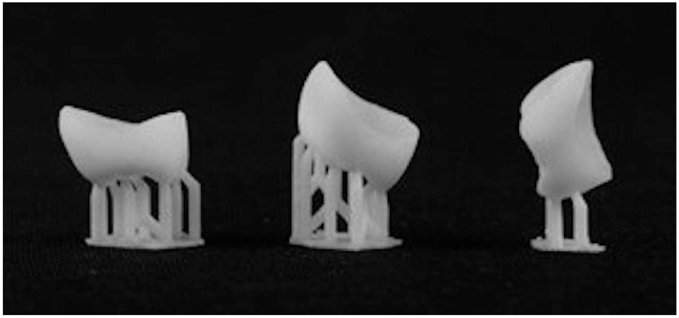
الخلفية تأثير تقنية الطباعة ثلاثية الأبعاد وزاوية البناء على الملاءمة الهامشية للتاجات المطبوعة غير واضح. كان الهدف من هذا البحث هو استخدام معالجة الضوء الرقمي (DLP) والطباعة ثلاثية الأبعاد المعتمدة على الاستريوليثوغرافيا (SLA) لبناء ترميمات فردية بزوايا بناء متنوعة وتحليل الملاءمة الهامشية للتاجات. الطرق تم مسح ضرس أول معدني مُعد باستخدام ماسح ضوئي بصري. تم استخدام ثلاث زوايا بناء لبناء العينات: 0، 45، و تم استخدام تقنيتي DLP وSLA لإنتاج نماذج الصب. تم استخدام ميكروسكوب رقمي لقياس الفجوات الهامشية. تم تحليل تأثير اتجاه البناء إحصائيًا باستخدام تحليل التباين ثنائي الاتجاه تلاه اختبار توكي الزوجي. أظهرت نتائج تحليل التباين ثنائي الاتجاه تأثيرًا كبيرًا لتقنية الطباعة وزاوية البناء على التباين الهامشي للتاجات المطبوعة ثلاثية الأبعاد. ” ). أظهر تحليل التباين الأحادي أن طابعات SLA (55.6 ) أظهرت متوسطًا أفضل بشكل ملحوظ اختلاف طفيف في من طابعات DLP (72 ) ( فيما يتعلق بزاوية البناء، أظهر تحليل التباين الأحادي (ANOVA) اختلافات كبيرة بين الزوايا المختلفة. وكشف اختبار توكي بعد الاختبار أن كان لديه أقل فرق هامشي بشكل ملحوظ يليه ثم . الخاتمة تؤثر اتجاه البناء على الفجوة الهامشية للتاج الواحد المُصنّع باستخدام DLP وSLA.

الكلمات الرئيسية: بناء التوجه، التكيف الهامشي السني، إسقاط الضوء الرقمي، الطباعة الحجرية المجسمة

الخلفية

لقد زاد استخدام التكنولوجيا الرقمية في الوقت الحاضر في مجال طب الأسنان الترميمي بشكل كبير [1،2]. تُستخدم تقنيات التصميم المدعوم بالحاسوب/التصنيع المدعوم بالحاسوب (CAD/CAM) من قبل تقنيات التصنيع الرقمي إما في التصنيع القائم على الإزالة (التفريز) أو التصنيع القائم على الإضافة (طباعة ثلاثية الأبعاد) [3]. تتمتع تقنيات التصنيع القائم على الإضافة بفائدة مميزة مقارنة بعمليات التفريز التقليدية، حيث إنها تنتج تقريبًا كمية ضئيلة من النفايات، ولا توجد قيود على التصميم الهندسي للمنتجات، ودقة المكونات المفروزة لم تعد مصدر قلق [4-6]. وهذا يمكّن تقنيات التصنيع القائم على الإضافة من أن تلعب دورًا كبيرًا في التصنيع الجماعي للعناصر ذات المواصفات الهندسية الفريدة [4].
تختلف طريقة التصنيع الإضافي (AM) بناءً على المادة المستخدمة، حيث تتضمن طريقة معالجة الضوء الرقمي (DLP) بناء بوليمر سائل بواسطة ضوء الأشعة فوق البنفسجية لتحقيق الشكل النهائي. يتم إنتاج هيكل معقد للغاية طبقة تلو الأخرى مباشرة من بيانات ثلاثية الأبعاد في عملية بناء DLP. اعتمادًا على الشكل النهائي المطلوب، يتم تعريض طبقات متتالية من المونومر السائل المنشط بالضوء للأشعة فوق البنفسجية وتصلبها. تقوم عملية DLP بإنشاء صورة قناع ديناميكية وعرضها على سطح الراتنج باستخدام جهاز المرايا الدقيقة الرقمية (DMD). تتحكم أجهزة DMD في اتجاه انعكاس الضوء من خلال استخدام مئات الآلاف من المرايا الدقيقة القابلة للتحرك بحرية. كل بكسل في الصورة يتوافق مع مرآة دقيقة واحدة، يمكن تغيير اتجاهها اعتمادًا على هندسة العنصر المطبوعة.
تعتبر تقنية الطباعة ثلاثية الأبعاد بالتصوير المجسم (SLA) غالبًا الأكثر أهمية واستخدامًا على نطاق واسع في العالم. يتم إنشاء كل طبقة في SLA بواسطة خطوط صغيرة تُنتج بواسطة شعاع ليزر UV مركز للغاية [11]. يتصلب البوليمر بينما يرسم الليزر الطبقة، تاركًا الأجزاء الزائدة في حالة سائلة. عند الانتهاء من طبقة، يتم استخدام شفرة تسوية لتنعيم السطح قبل تطبيق الطبقة التالية. يتم خفض المنصة بسمك الطبقة (عادةً ثم يتم إنشاء الطبقة التالية فوق الطبقات التي تم الانتهاء منها سابقًا. تتكرر عملية التتبع والتنعيم حتى تكتمل عملية البناء. عندما تكتمل القطعة، يتم رفعها فوق الحوض وتصريفها. عندما تكتمل عملية البوليمرة لطبقة واحدة، تنزلق منصة البناء أو خزان الراتنج لأعلى أو لأسفل بالنسبة لسمك الطبقة. يتم تحديد اتجاه الحركة بناءً على ما إذا كانت عملية البناء من الأعلى إلى الأسفل أو من الأسفل إلى الأعلى. بعد المعالجة النهائية، يتم تلميع الأسطح، وصقلها، وإكمالها.
نظرًا لمبدأ الإنتاج الأساسي طبقة تلو الأخرى في الطباعة ثلاثية الأبعاد، فإن اتجاه البناء يؤثر على العناصر في الطباعة ثلاثية الأبعاد بطريقة مختلفة جوهريًا عن التصنيع القائم على الإزالة. ذكر هونغ وآخرون أن اختيار اتجاه البناء الصحيح يحسن
الدقة الحجمية، تقلل من وقت وتكلفة التصنيع، وتقلل من عدد الدعامات المطلوبة للطباعة [14]. من خلال الاستفادة الكاملة من مصدر الضوء، واحدة من الميزات التي قد تحسن الدقة الهندسية والجودة الهيكلية للعنصر النهائي المطبوعة بتقنية الطباعة ثلاثية الأبعاد هي تخصيص زاوية/اتجاه البناء أثناء عملية البناء [15].
يمكن ببساطة تعديل سمك الأسمنت ومكانه، على سبيل المثال، في تكييف نماذج CAD، وقد استخدم بعض الباحثين مسافة الأسمنت [16، 17]. ومع ذلك، قد تكون مسافة الأسمنت الأكثر سمكًا مناسبة للتطبيقات العلاجية، مثل استخدام مادة لاصقة ذات قوة ارتباط عالية، فقد تعزز تكيف التيجان والأطراف الصناعية السنية الثابتة [11، 18].
خلصت عدة دراسات إلى أن التيجان المطبوعة بتقنية الطباعة ثلاثية الأبعاد توفر ملاءمة أفضل ودقة أعلى من التيجان المفرومة [5، 19، 20]. كما خلصت دراسات أخرى إلى أن زاوية البناء لها تأثير مباشر على دقة التيجان المؤقتة. لذا، كان هدف هذه الدراسة هو تقييم تأثير تقنية الطباعة ثلاثية الأبعاد واتجاه البناء على الدقة الهامشية للتاج الدائم.
الفرضية الصفرية الأولى هي أن الدقة الهامشية للتاج لا تتأثر بتقنية الطباعة ثلاثية الأبعاد. الفرضية الصفرية الثانية هي أن اتجاه البناء لن يؤثر على الدقة الهامشية.

طرق

في هذه الدراسة المخبرية، تم تصنيع 60 تاجًا كاملًا من الأضراس السفلية. تم تقسيم التيجان إلى مجموعتين ( وفقًا لتقنية الطباعة (المجموعة 1؛ DLP والمجموعة 2؛ SLA). تم تقسيم كل مجموعة إلى 3 مجموعات فرعية وفقًا لزاوية بناء الطباعة (المجموعة الفرعية أ؛ ، المجموعة الفرعية ب؛ ، والمجموعة الفرعية ج؛ تم تقييم التيجان لاحقًا من حيث الدقة الهامشية على الأسنان الداعمة المقابلة لها.
تم تقليل سن الضرس الأول الفك السفلي المصنوع من الراتنج (Nissin Dental، كيوتو، اليابان) بمقدار 2 مم على السطح الإطباقي وإجمالي زاوية التقارب مع خط إنهاء مائل عميق بسمك 1 مم. تم استخدام ماسح نموذج (E2: 3Shape كوبنهاغن، الدنمارك) لمسح الضرس المُعد. بمجرد تحويل بيانات المسح إلى تنسيق STL، تم استخدام برنامج CAD (Galway 3.0؛ Exocad، دارمشتات، ألمانيا) لتصميم تاج ضرس واحد. تم ضبط فجوة الأسمنت على .
تم استيراد التاج المصمم إلى برنامج للطباعة ثلاثية الأبعاد. بالنسبة لتيجان DLP، تم استخدام برنامج 3D Sprint (3D Systems، سوستربيرغ، هولندا) بينما تم استخدام برنامج Preform (Formlabs، سومرفيل، ماساتشوستس، الولايات المتحدة الأمريكية) لتيجان SLA. في برنامج الطابعة ثلاثية الأبعاد، تم وضع التيجان على منصة وتدويرها وفقًا لكل اتجاه بناء. كان الاتجاه عندما كانت السطح الإطباقي للتاج موازياً للمنصة. تم تدوير صورة التاج
الشكل 1 تيجان مطبوعة بتقنية الطباعة ثلاثية الأبعاد بزاويا بناء مختلفة
على طول المحور الطويل للتاج للحصول على توجيهات البناء. لدعم نمط الصب المصنوع من الفوتوبوليمر، تم تثبيت قضبان أسطوانية على القمم الخدّية، والقمم اللسانية، والحواف الهامشية. تم وضع السطح اللساني للتاج عموديًا على إطار الدعم لزاوية بناء قدرها (الشكل 1).
تم استخدام طابعة DLP (5100؛ نيكستدنت، سوستربيرغ، هولندا) ومواد فوتوبوليمر سائلة (C&B؛ نيكستدنت، 3D Systems، سوستربيرغ، هولندا) لطباعة 30 تاجًا. بينما تم طباعة 30 تاجًا آخر باستخدام تقنية الستيريو ليثوغرافي (Form 2؛ فورم لابز، سومرفيل، ماساتشوستس، الولايات المتحدة الأمريكية) في مادة راتنج مركب هجين (راتنج التاج الدائم؛ فورم لابز، سومرفيل، ماساتشوستس، الولايات المتحدة الأمريكية). تم ضبط سمك الطبقة لجميع العينات على .
وفقًا لتعليمات الشركة المصنعة، تم تنظيف مطبوعات DLP لمدة 5 دقائق بـ 2-بروبانول (Emsure؛ ميرك، دارمشتات، ألمانيا)، ثم تم علاجها لمدة 45 دقيقة باستخدام جهاز علاج بالضوء (3D systems؛ LC-3D Print Box، سوستيربرغ، هولندا).
وفقًا لتعليمات الشركة المصنعة، تم تنظيف العينات المطبوعة بتقنية الستيريو ليثوغرافي في الإيثانول لمدة دقيقة واحدة ثم تم علاجها بعد الطباعة لمدة 30 دقيقة باستخدام وحدة علاج بالأشعة فوق البنفسجية (S2؛ DWS، ثييني، إيطاليا). بعد ذلك، تم حفظ جميع العينات لمدة عشرة أيام في صندوق جاف ومضاد للضوء (Multiroir، بيريني، فرنسا) قبل الفحص.
تم تقييم الفجوة الهامشية عن طريق قياس المسافة الرأسية بين كل حافة تاج مصنوعة وخط إنهاء التحضير المقابل للركيزة بالتوازي مع محور السن. تم إجراء القياسات لكل تاج على طول المحيط في منتصف الأسطح البوكالية، والوسطى، واللسانية، والبعيدة. تم فحص جميع العينات عند تكبير تحت عدسة المجهر الرقمي USB مع كاميرا مدمجة (Scope Capture Digital Microscope، قوانغدونغ، الصين) متصلة بجهاز كمبيوتر شخصي متوافق مع IBM. صورة رقمية
الجدول 1 المتوسط (SD) وقيمة p لـ ANOVA للفجوة الهامشية بالميكرون لكل طابعة بزاويا مختلفة
زاوية البناء
نوع الطابعة
قيمة P
SLA
DLP
تم استخدام نظام التحليل (Image J 1.43U؛ المعهد الوطني للصحة، ماريلاند، الولايات المتحدة الأمريكية) لقياس وتقييم عرض الفجوة نوعيًا. تم التقاط جميع الصور، وتمت القياسات في المواقع الأربعة. تم تسجيل متوسط المواقع الأربعة معًا (البوكالي، والوسطى، واللساني، والبعيد) وأخذها كمتوسط نهائي لكل عينة.
تم التحقق من البيانات المجمعة للتوزيع الطبيعي باستخدام اختبارات Kolomgrov-Smirnov وShapiro-Wilk وتم تحليلها باستخدام تحليل التباين أحادي الاتجاه وثنائي الاتجاه (ANOVA)، تليها اختبار Tukey’s HSD (SPSS Statistics for Windows، الإصدار 20.0؛ IBM، أرمونك، نيويورك، الولايات المتحدة الأمريكية) عند مستوى دلالة .

النتائج

المتوسط (SD) لجميع المجموعات الفرعية في مدرجة في الجدول 1. أظهر تحليل التباين ثنائي الاتجاه تأثيرًا كبيرًا لتقنية الطابعة وزاوية البناء على الفجوة الهامشية للتاجات المطبوعة بتقنية 3D ( ). أظهر تحليل التباين أحادي الاتجاه أن طابعات SLA (55.6 ) أظهرت متوسطًا أفضل بشكل ملحوظ SD الفجوة الهامشية في من طابعات DLP ( ) ( ). فيما يتعلق بزوايا البناء، أظهر تحليل التباين أحادي الاتجاه اختلافات كبيرة بين الزوايا المختلفة. أظهر اختبار Tukey’s post-hoc أن كان لديه الفجوة الهامشية الأصغر بشكل ملحوظ تليها ( ) ثم .

المناقشة

تم إجراء هذه الدراسة لتقييم تأثير تقنية الطباعة ثلاثية الأبعاد واتجاه البناء على دقة الفجوة الهامشية لتاجات الأضراس السفلية الأولى. نتيجة لذلك، اختلفت ملاءمة الهامش اعتمادًا على اتجاهات البناء. تم رفض الفرضية الصفرية بناءً على نتائج الفحص المقارن لملاءمة الهامش لأسلوبي القياس.
تم استخدام ثلاث زوايا بناء مختلفة لطباعة تاجات الأسنان ذات التغطية الكاملة بتقنية 3D. تم اتخاذ عدة خطوات لتقليل والقضاء على جميع الأخطاء المحتملة في التعامل والمعالجة. في مركز منصة البناء، تم طباعة كل تاج بشكل فردي. تمت عمليات التصنيع والعلاج بعد الطباعة بواسطة ممارس مدرب واحد من التقنيتين. بناءً على الأبحاث السابقة، تم التخطيط لمساحة الأسمنت لتكون [16، 17]. كانت مساحة الأسمنت السميكة ستزيل الفجوات الطفيفة بين التعديلات [11، 18، 21].
من حيث دقة الطباعة، والجودة، والسرعة، والتكلفة، وملاءمة الطابعة، تعتبر تقنيات SLA وDLP هي أكثر تقنيات الطباعة ثلاثية الأبعاد استخدامًا في طب الأسنان. نتيجة لذلك، كانت التقنيات المختارة المستخدمة في هذه الدراسة. في الوقت نفسه، تتميز تقنية الستيريو ليثوغرافي بدقتها العالية في التصنيع، مما يؤدي إلى ملاءمة أكثر راحة ودقة لتاج الأسنان. يتم تكرار المنحنيات، والثقوب، والأشكال الأكثر تعقيدًا بسهولة ودقة أكبر، ويتم تصنيع القطعة تمامًا كما هو محدد، دون أي هدر [22]. تم اختيار الحد الأدنى من سمك الطبقة لكل طابعة ثلاثية الأبعاد والتي كانت .
تم قياس الفجوة الهامشية باستخدام المجهر الرقمي. هذه الطريقة مستخدمة على نطاق واسع، حيث إنها غير مدمرة، ولا حاجة للمواد الوسيطة مثل مواد الانطباع أو الأسمنت اللصق بينهما، ويمكن إجراء القياسات في مواقع مختلفة [23، 24].
يعتقد أن اتجاه البناء يؤثر على خصائص العناصر المعالجة بالضوء. بسبب الأبحاث السابقة التي أنتجت FDPs في شكل شريط أو تاج باستخدام الستيريو ليثوغرافي أو DLP، تم اختيار ، و زوايا البناء [18، 21، 25، 26]. أفاد بارك وآخرون أن اتجاه فجوة الهامش لـ FDPs المؤقتة المعتمدة على البوليمر كان مقبولًا سريريًا [27].
كانت فجوة الهامش لجميع العينات، مع زوايا بناء مختلفة، تحت الحدود المسموح بها سريريًا لـ [28]. قد تحتوي العينات ذات الاتجاهات الإنشائية المختلفة على اختلافات في الفجوة الهامشية بسبب البوليمرة المفرطة عند الجدار البوكالي الداخلي مع منطقة اختراق ضوء مختلفة [29-31]. كانت فجوات الهامش للعينات أكبر بكثير من تلك الخاصة بـ و العينات. كانت البوليمرة المفرطة أعلى عند السطح الداخلي البوكالي لعينات لأن الجدار البوكالي لعينة تم إنشاؤه بواسطة
الضوء الذي يدخل منطقة أوسع مع مسافة اختراق أقصر من تلك الخاصة بـ و العينات [21].
تقطيع عنصر ثلاثي الأبعاد إلى طبقات، والتي تتم طباعتها بشكل فردي ثم تتكدس لتتفاعل معًا وتبني الجسم المطلوب تدريجيًا، هو الخطوة الأولى في عملية الطباعة ثلاثية الأبعاد. “تأثير الدرج” هو ظاهرة يمكن أن تحدث عند طباعة العناصر مع اتجاهات بناء مائلة. في هذه الظاهرة، يتم طباعة الطبقات تدريجيًا وتؤدي الحواف بينهما إلى أخطاء [15، 32]. لذلك، من المعقول أن نفترض أن و الاتجاهات ستنتج دقة أقل من الاتجاه [33].
في العينات ذات الاتجاهات الإنشائية المختلفة، قد تؤدي الجاذبية إلى تشويه المنطقة التي تتدلى فوق الجدران البوكالية واللسانية، مما يغير حجم الفجوات الهامشية. تتماشى هذه النتائج مع تلك الخاصة بـ ريو وآخرون [11]، أن اتجاه هو الأفضل (تم تحويله إلى في الدراسة الحالية) ولكنها تتعارض مع بارك وآخرون [27] الذين اقترحوا اتجاه بناء بدلاً من .
اكتشفت تحقيقات أخرى أيضًا تأثير الهياكل الداعمة. أفاد يو وآخرون أن بروستhesis الراتنجية التي تم إنتاجها باستخدام طابعة SLA ثلاثية الأبعاد كانت ذات جودة رديئة في الحواف القريبة من موصل الدعم وغالبًا ما كانت لها حواف خشنة [6]. يختلف موضع موصل الدعم مع زاوية البناء. قد تؤدي الأجزاء غير المدعومة إلى أخطاء. إذا كان الدعم متصلًا بالقرب من حافة التاج، فقد يتسبب ذلك في ضرر أثناء الإزالة [18]. بحث الحربي وآخرون في دقة الأبعاد لزاوية البناء لتاجات الأسنان المصنوعة باستخدام طابعة DLP ثلاثية الأبعاد، كانت خطأ الجذر التربيعي المتوسط (RMSE) أعلى في المنطقة التي تحتوي على هيكل الدعم [18]. يختلف موضع موصل الدعم مع زاوية البناء. قد تؤدي الأجزاء غير المدعومة إلى أخطاء. إذا كان الدعم متصلًا بالقرب من حافة التاج، فقد يتسبب ذلك في ضرر أثناء الإزالة. في الوقت نفسه، يختلف شكل الطبقة التي أنشأتها الطابعة ثلاثية الأبعاد وفقًا لزاوية البناء، وهو سبب للاختلافات في الملاءمة الهامشية. تقوم طابعة ثلاثية الأبعاد المعتمدة على DLP بتجفيف طبقة واحدة في كل مرة، وأي تغيير في شكل الطبقة يتطلب تغييرات في الشكل ودرجة انكماش البوليمرة. تستخدم تقنية SLA ليزر الأشعة فوق البنفسجية (UV) لعلاج المادة نقطة بنقطة [25، 26].
اختيار زاوية البناء أمر حاسم لأنه يؤثر على كمية الهياكل الداعمة المطلوبة، والتي قد تؤثر على دقة المكونات المصنعة [18]. يزداد عدد الأسطح المدعومة ذاتيًا وينخفض عدد الهياكل الداعمة عندما يتم تدوير التاج من زاوية بناء إلى زاوية بناء . في زاوية البناء تم وضع الهيكل الداعم بالقرب من المنطقة الهامشية للتاج. هذا يعزز إمكانية أنه عند إزالة الهياكل الداعمة، قد يتسبب ذلك في ضرر لهذه المنطقة المهمة.
قد يتعرض جزء من الترميم للتلف. تم وضع الدعم بعيدًا عن حواف التاج في زاوية البناء. نظرًا لأن معظم أسطح التاج المطبوعة كانت ذاتية الدعم، فإن عملية التشطيب والتلميع كانت تتطلب وقتًا ومساحة سطح دعم أقل.
في هذا البحث، كانت القيم المتوسطة للفجوة الهامشية لـ و زوايا البناء مع SLA، على التوالي، كانت 40 و ، بينما القيمة المتوسطة لـ زاوية البناء كانت . تفسير ذلك هو، بالمقارنة مع زاوية، زاوية التاج عند و زودت بأكثر الهندسة ذاتية الدعم.
أظهرت الأبحاث الحديثة التي اختبرت الدقة الهندسية للتاج المطبوخ بتقنية SLA قيمة قصوى تبلغ 0.042 مم، وهي لا تزال أصغر من أصغر تباين تم ملاحظته باستخدام DLP [18]. ويرجع ذلك إلى التمييز بين إجراءات الإنتاج. تؤثر المعلمات البصرية للنظام، مثل جهاز DMD، وجودة العدسة، وحجم البكسل، ودقة المنصة، بشكل إضافي على دقة الطباعة بتقنية DLP [7، 9]. بالإضافة إلى ذلك، تدعم هذه النتائج الادعاءات التي تم تقديمها في عدد من الدراسات في الأدبيات بأن طريقة SLA هي واحدة من أكثر تقنيات التصنيع الإضافية دقة. ومع ذلك، أظهرت الدراسات أنه لا توجد طريقة طباعة ثلاثية الأبعاد واحدة أفضل من الأخرى وأن التكنولوجيا المختارة بشكل جيد ستؤدي الغرض المطلوب [34، 35].
على الرغم من أن نتائج هذه الدراسة قد تكون واعدة، إلا أنه يجب إجراء المزيد من التحقيقات لتحديد تأثيرات العديد من الجوانب، بما في ذلك موضع المنصة، نوع الدعم، وسمك الطبقة، التي يجب أخذها في الاعتبار أثناء طباعة التيجان. أيضًا، تم إجراء هذه الدراسة على التيجان الفردية، لذا يمكن فحص الأطوال الأطول أو الترميمات داخل التاج في الدراسات المستقبلية.

الاستنتاجات

  1. تؤثر تقنية الطباعة بشكل مباشر على الدقة الهامشية للتاج الدائم المطبوعة بتقنية الطباعة ثلاثية الأبعاد.
  2. زاوية الطباعة لها تأثير على الدقة الهامشية.
  3. أظهرت جميع المتغيرات المختبرة نتائج ضمن النطاق المقبول سريرياً.

شكر وتقدير

يود المؤلفون أن يشكروا الموظفين في مركز العلوم السنية الابتكارية (CIDS)، كلية dentistry، الجامعة البريطانية في مصر.

مساهمات المؤلفين

قام E.F. بتصميم الدراسة. أكمل A.S. و O.S. و K.E. التجربة. كتب O.S. و E.F. المخطوطة. قام K.E. بمراجعة المخطوطة. وافق جميع المؤلفين على المخطوطة النهائية.

تمويل

لا توجد تمويلات للإعلان. تم توفير تمويل الوصول المفتوح من قبل هيئة تمويل العلوم والتكنولوجيا والابتكار (STDF) بالتعاون مع البنك المصري للمعرفة (EKB).

توفر البيانات

تتوفر مجموعات البيانات المستخدمة و/أو التي تم تحليلها خلال الدراسة الحالية من المؤلف المراسل عند الطلب المعقول.

الإعلانات

غير قابل للتطبيق.
غير قابل للتطبيق.

المصالح المتنافسة

يعلن المؤلفون عدم وجود مصالح متنافسة.
تاريخ الاستلام: 13 مايو 2023 / تاريخ القبول: 2 يناير 2024
نُشر على الإنترنت: 11 يناير 2024

References

  1. Ebeid K, Nouh I, Ashraf Y, Cesar PF. Accuracy of different laboratory scanners for scanning of implant-supported full arch fixed prosthesis. J Esthet Restor Dent. 2022;34:843-8. https://doi.org/10.1111/jerd.12918.
  2. Ebeid K, Sabet A, El Sergany O, Della Bona A. Accuracy and repeatability of different intraoral instruments on shade determination compared to visual shade selection. J Esthet Restor Dent. 2022;34:988-93. https://doi. org/10.1111/jerd.12884.
  3. Ellakany P, Tantawi M, El, Mahrous AA, Al-Harbi F. Evaluation of the accuracy of digital impressions obtained from intraoral and extraoral dental scanners with different CAD/CAM scanning technologies: an in vitro study. J Prosthodont. 2022;31:314-9. https://doi.org/10.1111/jopr.13400.
  4. Azari A, Nikzad S. The evolution of rapid prototyping in dentistry: a review. Rapid Prototyp J. 2009;15:216-25. https://doi. org/10.1108/13552540910961946.
  5. Ottoni R, Marocho SMS, Griggs JA, Borba M. CAD/CAM versus 3D-printing/ pressed lithium disilicate monolithic crowns: adaptation and fatigue behavior. J Dent. 2022;123:104181. https://doi.org/10.1016/j.jdent.2022.104181.
  6. Yu BY, Son KB, Da, Lee KB. Evaluation of intaglio surface trueness and margin quality of interim crowns in accordance with the build angle of stereolithography apparatus 3-dimensional printing. J Prosthet Dent. 2021;126:231-7. https://doi.org/10.1016/j.prosdent.2020.04.028.
  7. Andersen UV, Pedersen DB, Hansen HN, Nielsen JS. In-process 3D geometry reconstruction of objects produced by direct light projection. Int J Adv ManufTechnol. 2013;68. https://doi.org/10.1007/s00170-013-4778-3.
  8. Wu GH, Hsu SH, Review. Polymeric-based 3D printing for tissue engineering. J Med Biol Eng. 2015;35:285-92. https://doi.org/10.1007/s40846-015-0038-3.
  9. Mitteramskogler G, Gmeiner R, Felzmann R, Gruber S, Hofstetter C, Stampfl J, et al. Light curing strategies for lithography-based additive manufacturing of customized ceramics. Addit Manuf. 2014;1:110-8. https://doi.org/10.1016/j. addma.2014.08.003.
  10. Lee MP, Cooper GJT, Hinkley T, Gibson GM, Padgett MJ, Cronin L. Development of a 3D printer using scanning projection stereolithography. Sci Rep. 2015;5. https://doi.org/10.1038/srep09875.
  11. Ryu JE, Kim YL, Kong HJ, Chang HS, Jung JH. Marginal and internal fit of 3D printed provisional crowns according to build directions. J Adv Prosthodont. 2020;12. https://doi.org/10.4047/jap.2020.12.4.225.
  12. Yan Y, Li S, Zhang R, Lin F, Wu R, Lu Q, et al. Rapid prototyping and manufacturing technology: principle, representative technics, applications, and development trends. Tsinghua Sci Technol. 2009;14:1-12. https://doi.org/10.1016/ S1007-0214(09)70001-X.
  13. Huotilainen E, Salmi M, Chekurov S, Flores Ituarte I. Effect of build orientation in 3D printing production for material extrusion, material jetting, binder jetting, sheet object lamination, vat photopolymerisation, and powder bed fusion. Int J Collab Enterp. 2016;5:218. https://doi.org/10.1504/ ijcent.2016.10003187.
  14. Hong J, Wu DL, Li DC, Lu BH. Multi-objective optimization of the part building orientation in stereolithography. Hsi-An Chiao Tung Ta Hsueh/Journal Xi’an Jiaotong Univ. 2001;35:506-9.
  15. Oropallo W, Piegl LA. Ten challenges in 3D printing. Eng Comput. 2016;32:135-48. https://doi.org/10.1007/s00366-015-0407-0.
  16. Habib SR, AI Otaibi AK, AI Anazi TA, AI Anazi SM. Comparison between five CAD/CAM systems for fit of zirconia copings. Quintessence Int. 2018;49:43744. https://doi.org/10.3290/j.qi.a40354.
  17. Zheng Z, Wang H, Mo J, Ling Z, Zeng Y, Zhang Y, et al. Effect of virtual cement space and restorative materials on the adaptation of CAD-CAM endocrowns. BMC Oral Health. 2022;22:580. https://doi.org/10.1186/s12903-022-02598-0.
  18. Alharbi N, Osman R, Wismeijer D. Factors influencing the dimensional accuracy of 3d-printed full-coverage dental restorations using stereolithography technology. Int J Prosthodont. 2016;29:503-10. https://doi.org/10.11607/ ijp.4835.
  19. Kakinuma H, Izumita K, Yoda N, Egusa H, Sasaki K. Comparison of the accuracy of resin-composite crowns fabricated by three-dimensional printing and milling methods. Dent Mater J. 2022;41:808-15. https://doi.org/10.4012/ dmj.2022-074.
  20. Abualsaud R, Alalawi H. Fit, precision, and trueness of 3d-printed zirconia crowns compared to milled counterparts. Dent J. 2022;10:215. https://doi. org/10.3390/dj10110215.
  21. Chaiamornsup P, Iwasaki N, Tsuchida Y, Takahashi H. Effects of build orientation on adaptation of casting patterns for three-unit partial fixed dental prostheses fabricated by using digital light projection. J Prosthet Dent. 2022;128:1047-54. https://doi.org/10.1016/j.prosdent.2021.01.006.
  22. Bammani SS, Birajdar PR, Metan SS. Dental crown manufacturing using stereolithography method. Proc Int Conf Adv Ind Prod Eng 2012:7-10.
  23. Torabi K, Vojdani M, Giti R, Taghva M, Pardis S. The effect of various veneering techniques on the marginal fit of zirconia copings. J Adv Prosthodont. 2015;7:233-9. https://doi.org/10.4047/jap.2015.7.3.233.
  24. Martínez-Rus F, Suárez MJ, Rivera B, Pradíes G. Evaluation of the absolute marginal discrepancy of zirconia-based ceramic copings. J Prosthet Dent. 2011;105:108-14. https://doi.org/10.1016/S0022-3913(11)60009-7.
  25. Tahayeri A, Morgan MC, Fugolin AP, Bompolaki D, Athirasala A, Pfeifer CS, et al. 3D printed versus conventionally cured provisional crown and bridge dental materials. Dent Mater. 2018;34:192-200. https://doi.org/10.1016/j. dental.2017.10.003.
  26. Unkovskiy A, Bui PHB, Schille C, Geis-Gerstorfer J, Huettig F, Spintzyk S. Objects build orientation, positioning, and curing influence dimensional accuracy and flexural properties of stereolithographically printed resin. Dent Mater. 2018;34:e324-33. https://doi.org/10.1016/j.dental.2018.09.011.
  27. Park GS, Kim SK, Heo SJ, Koak JY, Seo DG. Effects of printing parameters on the fit of implant-supported 3D printing resin prosthetics. Mater (Basel). 2019;12. https://doi.org/10.3390/ma12162533.
  28. McLean JW, Von F. The estimation of cement film thickness by an in vivo technique. Br Dent J. 1971;131:107-11. https://doi.org/10.1038/sj.bdj.4802708.
  29. Revilla-León M, Meyers MJ, Zandinejad A, Özcan M. A review on chemical composition, mechanical properties, and manufacturing work flow of additively manufactured current polymers for interim dental restorations. J Esthet Restor Dent. 2019;31:51-7. https://doi.org/10.1111/jerd.12438.
  30. Chaiamornsup P, Iwasaki N, Yasue T, Uo M, Takahashi H. Effects of build conditions and angle acuteness on edge reproducibility of casting patterns fabricated using digital light projection. Dent Mater J. 2020;39:135-40. https://doi. org/10.4012/dmj.2018-401.
  31. Vitale A, Cabral JT. Frontal conversion and uniformity in 3D printing by photopolymerisation. Mater (Basel). 2016;9. https://doi.org/10.3390/ma9090760.
  32. Pandey PM, Venkata Reddy N, Dhande SG. Part deposition orientation studies in layered manufacturing. J Mater Process Technol. 2007;185:125-31. https:// doi.org/10.1016/j.jmatprotec.2006.03.120.
  33. Derban P, Negrea R, Rominu M, Marsavina L. Influence of the printing angle and load direction on flexure strength in 3d printed materials for provisional dental restorations. Mater (Basel). 2021;14. https://doi.org/10.3390/ ma14123376.
  34. Melchels FPW, Feijen J, Grijpma DW. A review on stereolithography and its applications in biomedical engineering. Biomaterials. 2010;31. https://doi. org/10.1016/j.biomaterials.2010.04.050.
  35. Liu Q, Leu MC, Schmitt SM. Rapid prototyping in dentistry: technology and application. Int J Adv ManufTechnol. 2006;29:317-35. https://doi. org/10.1007/s00170-005-2523-2.

ملاحظة الناشر

تظل شركة سبرينجر ناتشر محايدة فيما يتعلق بالمطالبات القضائية في الخرائط المنشورة والانتماءات المؤسسية.

  1. *المراسلات:
    كمال عبيد
    كمال عبيد@dent.asu.edu.eg
    قسم التعويضات الثابتة، كلية طب الأسنان، البريطانية
    جامعة في مصر، القاهرة، مصر
    قسم التعويضات الثابتة، كلية dentistry، جامعة عين شمس
    جامعة، شارع منظمة الوحدة الأفريقية، القاهرة، مصر

Journal: BMC Oral Health, Volume: 24, Issue: 1
DOI: https://doi.org/10.1186/s12903-024-03851-4
PMID: https://pubmed.ncbi.nlm.nih.gov/38212816
Publication Date: 2024-01-11

Build angle effect on 3D-printed dental crowns marginal fit using digital lightprocessing and stereo-lithography technology: an in vitro study

Engy Farag , Ahmed Sabet , Kamal Ebeid and Omar El Sergany

Abstract

Background The effect of 3D printing technology and build angle on the marginal fit of printed crowns is unclear. The objective of this research was to use digital light processing (DLP) and stereo-lithography (SLA)-based 3D printing to construct single restorations with varied build angles and to analyze the crowns’ marginal fit. Methods A prepared resin first molar was scanned utilizing an optical scanner. Three build orientations were used to construct the specimens: 0,45 , and . DLP and SLA technology were used to produce the casting patterns. A digital microscope was used to measure the marginal gaps. The effect of build orientation was statistically analyzed by using Two-way ANOVA followed by pair-wise Tukey test. Results Two-way ANOVA revealed a significant effect of printer technology and build angle on the marginal discrepancy of 3D printed crowns ( ). One-way ANOVA revealed that SLA printers (55.6 ) showed significantly better mean marginal discrepancy in than DLP printers (72 ) ( ). Regarding build angle, one-way ANOVA revealed significant differences between the different angles. Tukeys post-hoc test revealed that had the significantly smallest marginal discrepancy followed by then . Conclusion The build orientation affects the marginal discrepancy of single crowns manufactured utilizing DLP and SLA.

Keywords Build orientation, Dental marginal adaptation, Digital light projection, Stereolithography

Background

The usage of digital technology nowadays in the field of restorative dentistry has increased significantly [1,2]. Computer-aided design/computer-aided manufacturing (CAD/CAM) techniques are used by digital fabrication technologies in either subtractive (milling) or additive (3D printing) manufacturing (AM) [3]. AM has a distinct benefit over traditional milling techniques processes in that it generates virtually little waste, there are no limitations on the products geometric design, and accuracy of milled components is no more a concern [4-6]. This enables AM technologies to have a significant role in the mass manufacture of items with unique geometrical specifications [4].
The AM method differs based on the material used, with the digital light processing (DLP) approach including the building of a liquid photopolymer by UV light to achieve the end shape [7]. A very complicated structure is produced layer by layer directly from 3D data in a DLP build process. Depending on the final shape of the desired outcome, successive layers of liquid photoactivated monomer are subjected to UV light and cured. The DLP process creates a mask image dynamically and displays it on the resin surface using a digital micromirror device (DMD) [8, 9]. DMDs control the direction of light reflection by utilizing hundreds of thousands of freely moveable micromirrors. Each pixel in the picture corresponds to a single micromirror, the orientation of which may be changed depending on the geometry of the printed item [10].
The stereolithography (SLA) is often regarded as the most significant and widely utilized 3D printing technique in the world. Each layer in SLA is done by small lines created by a highly concentrated UV laser beam [11]. The polymer hardens as the laser traces the layer, leaving the surplus portions as liquid. When a layer is finished, a levelling blade is used to smooth the surface before applying the following layer. The platform is lowered by the thickness of the layer (usually ), and the next layer is created on top of the previously finished layers. This tracing and smoothing operation is repeated until the construction is finished. When the part is finished, it is lifted over the vat and drained. When the polymerization of one layer is complete, the build platform or resin tank slides up or down with relation to the layer’s thickness. The travelling direction is determined by whether the construction process is top-down or bot-tom-up. After the final cure, the surfaces are polished, sanded, and completed [12].
Because of the basic layer-by-layer production principle of 3D printing, build orientation impacts items in 3D printing in a fundamentally distinct manner than subtractive manufacturing [13]. Hong et al. stated that selecting the correct construction orientation improves
volumetric accuracy, decreases manufacturing time and cost, and reduces the number of supports required for printing [14]. By making full use of the light source, one of the features that may improve the geometrical precision and structural quality of the final 3D-printed item is customizing build angle/orientation during the build process [15].
The cement space thickness and placement, for example, may be simply adjusted in the adaption of CAD models, and some researchers have employed a cement space [16, 17]. However, a thicker cement spacing may be appropriate for therapeutic applications, like utilizing a luting substance with a high bonding strength, it might enhance crown and fixed dental prosthesis adaption [11, 18].
Several studies concluded that 3D printed crowns offer a better fit and higher precision than milled crowns [5, 19, 20]. Other studies also concluded that build angle have a direct effect on the accuracy of provisional crowns . Thus, the aim of this study was to evaluate the effect of 3D printing technology and build orientation on marginal accuracy of permanent crowns.
The first null hypothesis is that the marginal accuracy of crowns is not affected by the 3D printing technology. The second null hypothesis is that build orientation will not influence the marginal accuracy.

Methods

In this in vitro study 60 full anatomical mandibular molar crowns were fabricated. Crowns were divided into two groups ( ) according to the printing technology (Group 1; DLP and group 2; SLA). Each group was divided into 3 subgroups ( ) according to the printing build angle (Subgroup A; , subgroup B; , and subgroup C; ). Crowns were later evaluated for marginal accuracy on their corresponding abutment tooth.
A mandibular first molar resin tooth (Nissin Dental, Kyoto, Japan) was reduced by 2 mm preparation on the occlusal surface and a total of convergence angle with a 1 mm circumferential deep chamfer finish line. A model scanner (E2: 3Shape Copenhagen, Denmark) was used to scan the prepared molar. Once the scan data has been converted to STL format, CAD software (Galway 3.0; Exocad, Darmstadt, Germany) was used to design a single molar crown. Cement gap was set to .
The designed crown was imported into a software for 3D printing. For DLP crowns, 3D sprint software (3D Systems, Soesterberg, Netherlands) was used while the Preform software (Formlabs, Somerville, MA, USA) was used for SLA crowns. In the 3D printer software, the crowns were positioned on a platform and rotated in accordance with each construction direction. The direction was when the crown’s occlusal surface set parallel to the platform. The crown image was rotated
Fig. 1 3D printed crowns with different build angles
along the long axis of the crown to get the construction orientations. To support the vat photopolymerized cast pattern, cylindrical rods were affixed to the buccal cusps, lingual cusps, and marginal ridges. The crown lingual surface was placed perpendicular to the support framework for a construction angle of (Fig. 1).
A DLP (5100; NexDent, Soesterberg, Netherlands) and liquid photopolymer (C&B; NexDent, 3D Systems, Soesterberg, Netherlands) were used to print 30 crowns. While the other 30 crowns were printed using stereolithography (Form 2; Formlabs, Somerville, MA, USA) in a hybrid composite resin material (Permanent crown resin; Formlabs, Somerville, MA, USA). The layer thickness for all samples was set to .
Following the manufacturer’s instructions, the DLP prints were cleaned for 5 min with 2-propanol (Emsure; Merck, Darmstadt, Germany), and then cured for 45 min using a light curing device (3D systems; LC-3D Print Box, Soesterberg, Netherlands).
In accordance with the manufacturer’s instructions, the stereolithography printed specimens were cleaned in ethanol for 1 min and then post-cured for 30 min with a UV curing unit (S2; DWS, Thiene, Italy). After that, all the samples were preserved for ten days in a dry, light-proof box (Multiroir, Perigny, Fance) before being inspected.
Marginal discrepancy was assessed by measuring the vertical distance between each fabricated crown margin and corresponding abutment preparation finish line parallel to the tooth axis. Measurements were done for each crown along the circumference at the mid of buccal, mesial, lingual and distal surfaces. All the samples were examined at magnification under the lens of USB digital microscope with a built-in camera (Scope Capture Digital Microscope, Guangdong, China) connected with an IBM compatible personal computer. A digital image
Table 1 Mean (SD) and p-value of ANOVA for the marginal gap in microns of each printer with different angles
Build angle
Printer type
P-Value
SLA
DLP
analysis system (Image J 1.43U; National Institute of Health, Maryland, USA) was used to measure and qualitatively evaluate the gap width. All the imaging was captured, and measurements were done at the four sites. The mean of the four sites together (buccal, mesial, lingual, and distal) were recorded and taken as the final mean for each sample.
The data collected was checked for normal distribution using Kolomgrov-Smirnov and Shapiro-Wilk tests and analyzed using one-way and two-way analysis of variances (ANOVA), followed by Tukey’s HSD test (SPSS Statistics for Windows, Version 20.0.; IBM, Armonk, NY, USA) at a significance level of .

Results

Mean (SD) for all subgroups in are listed in Table 1. Two-way ANOVA revealed a significant effect of printer technology and build angle on the marginal discrepancy of 3D printed crowns ( ). One-way ANOVA revealed that SLA printers (55.6 ) showed significantly better mean SD marginal discrepancy in than DLP printers ( ) ( ). Regarding build angle, one-way ANOVA revealed significant differences between the different angles. Tukeys post-hoc test revealed that had the significantly smallest marginal discrepancy followed by ( ) then .

Discussion

This study was conducted to evaluate the effect of 3D printing technology and build orientation on marginal accuracy of lower first molar crowns. As a result, the marginal fit varied depending on the construction directions. The null hypothesis was rejected based on the findings of the comparative examination of margin fitness for the two measurement methodologies.
Three different build angles were utilized to 3D print full-coverage dental crowns. Several steps were made to reduce and eradicate all possible handling and processing faults. In the center of the build platform, each crown was printed individually. The fabrication and post-curing processes were carried out by a single trained practitioner of the two technologies. Based on earlier research, the cement space was planned to be [16, 17]. Thick cement space would have removed minor discrepancies between the modifications [11, 18, 21].
In terms of printing accuracy, quality, speed, affordability, and printer compactness, SLA and DLP technologies are the most often utilized 3D printing technologies in dentistry. As a result, they were the technologies of choice employed in this study. Meanwhile, the stereolithography technique is distinguished by its great manufacturing precision, which results in a more comfortable and exact fit of the dental crown. Curves, holes, and more complicated shapes are duplicated more easily and correctly, and the piece is manufactured exactly as specified, with no waste [22]. The minimum layer thickness was chosen for each 3D printer which was .
The marginal discrepancy was measured using the digital microscope. This method is widely used, since it is nondestructive, there is no need for intermediate materials such as impression materials or luting cement in between and the measurements can be carried out at various sites [23,24].
It is believed that build orientation affects the characteristics of photopolymerized items. Due to past research that produced FDPs in the forms of a bar or a crown using stereolithography or DLP, the , and build orientations were chosen [18, 21, 25, 26]. Park et al. reported that the orientation of interim polymerbased FDPs’ marginal gap was clinically acceptable [27].
All specimens’ marginal gap, with different build orientation, was under the clinically permitted limits of [28]. Specimens with different construction orientations may have marginal gap differences due to excessive polymerization at the intaglio buccal wall with different light penetration area [29-31]. The specimens’ marginal gaps of were substantially larger than those of and specimens. Excessive polymerization is highest at the buccal intaglio surface of samples because the buccal wall of the sample is created by
light entering a broader area with a shorter penetrating distance than that of the and samples [21].
Virtually cutting a 3D item into layers, which are then printed individually and stacked to copolymerize and gradually construct the desired object, is the first step in the 3D printing process. The “staircase effect” is a phenomenon that can happen when printing objects with inclined construction orientations. In this phenomenon, layers are printed gradually and the step edges between them result in errors [15, 32]. Therefore, it is reasonable to assume that the and orientations will produce less accuracy than the orientation [33].
In specimens with different construction orientations, gravity may distort the area that hangs over the buccal and lingual walls, changing the size of the marginal gaps. These findings are in line with those of Ryu et al. [11], that a building orientation is best (converted to in the present study) but disagree with of Park et al. [27] who suggested a construction orientation rather than .
Other investigations also discovered the impact of the supporting structures. Yu et al. reported that a resin prosthesis produced using a SLA 3D printer had poor quality of the margins close to the support attachment and frequently had roughened edges [6]. The support attachment position varies with the construction angle. Unsupported sections might cause errors. If the support is connected near to the crown margin, it may cause harm during removal [18]. Alharbi et al. investigated the dimensional accuracy of the build orientation of dental crowns fabricated with a DLP 3D printer, the root mean square error (RMSE) was higher in the area with the support structure [18]. The support attachment position varies with the construction angle. Unsupported sections might cause errors. If the support is connected near to the crown margin, it may cause harm during removal. Meanwhile, the form of the layer created by the 3D printer differs according to the build angle which is a reason for the differences in the marginal fit. A DLP-based 3D printer polymerizes one layer at a time, any change in the layer form entails changes in the form and degree of polymerization shrinkage. SLA technology employs an ultraviolet (UV) laser to cure material point by point [25, 26].
The choice of construction angle is crucial since it influences the amount of support structures required, which may have an impact on the precision of the created components [18]. The number of surfaces that are selfsupported increases and the support structures number decreases when the crown is rotated from a construction angle to a build angle. In the construction angle, the support structure was placed close to the marginal area of crown. This enhances the possibility that when the support structures are removed, this important
part of the restoration may undergo damage. Support was set back from the crown edges in the construction angle. Since most of the printed crown’s surfaces were self-supporting, finishing and polishing required less time and support surface area.
In this research, the marginal gap mean values for the and build angles with the SLA, respectively, were 40 and , while the mean value for the build angle was . The explanation of that is, as compared to the angle, the crown’s angulation at and supplied the most self-supporting geometry.
Recent research that tested the geometric precision of the SLA-fabricated printed crown showed a maximum value of 0.042 mm , which is still smaller than the smallest variation observed with DLP [18]. This is due to the distinction between the two production procedures. The optical parameters of the system, such as the DMD device, lens quality, pixel size, and platform resolution, have an additional influence on the DLP printing precision [7, 9]. Additionally, these results support the claims made in a number of studies in the literature that the SLA method is one of the most precise manufacturing additive technologies. However, studies showed that there is no one 3D printing method that is better than another and that a well picked technology will perform the needed purpose [34, 35].
Although the results of this study maybe promising, there needs to be more investigations to determine the effects of numerous aspects, including platform position, support type, and layer thickness, that should be taken into account while printing crowns. Also, this study was done on single crowns, thus longer spans or intracoronal restorations may be further examined in future studies.

Conclusions

  1. Printing technology has a direct effect on the marginal accuracy of 3D printed permanent crowns.
  2. Printing build angle has an effect on the marginal accuracy.
  3. All tested variables showed results within the clinically acceptable range.

Acknowledgements

The authors would like to thank the staff at the Center of innovative dental sciences (CIDS), Faculty of Dentistry, British University in Egypt.

Author contributions

E.F. did the study design. A.S., O.S., and K.E completed the experiment. O.S. and E.F. wrote the manuscript. K.E. revised the manuscript. All authors approved the final manuscript.

Funding

No funding to declare. Open access funding provided by The Science, Technology & Innovation Funding Authority (STDF) in cooperation with The Egyptian Knowledge Bank (EKB).

Data availability

The datasets used and/or analysed during the current study available from the corresponding author on reasonable request.

Declarations

Not applicable.
Not applicable.

Competing interests

The authors declare no competing interests.
Received: 13 May 2023 / Accepted: 2 January 2024
Published online: 11 January 2024

References

  1. Ebeid K, Nouh I, Ashraf Y, Cesar PF. Accuracy of different laboratory scanners for scanning of implant-supported full arch fixed prosthesis. J Esthet Restor Dent. 2022;34:843-8. https://doi.org/10.1111/jerd.12918.
  2. Ebeid K, Sabet A, El Sergany O, Della Bona A. Accuracy and repeatability of different intraoral instruments on shade determination compared to visual shade selection. J Esthet Restor Dent. 2022;34:988-93. https://doi. org/10.1111/jerd.12884.
  3. Ellakany P, Tantawi M, El, Mahrous AA, Al-Harbi F. Evaluation of the accuracy of digital impressions obtained from intraoral and extraoral dental scanners with different CAD/CAM scanning technologies: an in vitro study. J Prosthodont. 2022;31:314-9. https://doi.org/10.1111/jopr.13400.
  4. Azari A, Nikzad S. The evolution of rapid prototyping in dentistry: a review. Rapid Prototyp J. 2009;15:216-25. https://doi. org/10.1108/13552540910961946.
  5. Ottoni R, Marocho SMS, Griggs JA, Borba M. CAD/CAM versus 3D-printing/ pressed lithium disilicate monolithic crowns: adaptation and fatigue behavior. J Dent. 2022;123:104181. https://doi.org/10.1016/j.jdent.2022.104181.
  6. Yu BY, Son KB, Da, Lee KB. Evaluation of intaglio surface trueness and margin quality of interim crowns in accordance with the build angle of stereolithography apparatus 3-dimensional printing. J Prosthet Dent. 2021;126:231-7. https://doi.org/10.1016/j.prosdent.2020.04.028.
  7. Andersen UV, Pedersen DB, Hansen HN, Nielsen JS. In-process 3D geometry reconstruction of objects produced by direct light projection. Int J Adv ManufTechnol. 2013;68. https://doi.org/10.1007/s00170-013-4778-3.
  8. Wu GH, Hsu SH, Review. Polymeric-based 3D printing for tissue engineering. J Med Biol Eng. 2015;35:285-92. https://doi.org/10.1007/s40846-015-0038-3.
  9. Mitteramskogler G, Gmeiner R, Felzmann R, Gruber S, Hofstetter C, Stampfl J, et al. Light curing strategies for lithography-based additive manufacturing of customized ceramics. Addit Manuf. 2014;1:110-8. https://doi.org/10.1016/j. addma.2014.08.003.
  10. Lee MP, Cooper GJT, Hinkley T, Gibson GM, Padgett MJ, Cronin L. Development of a 3D printer using scanning projection stereolithography. Sci Rep. 2015;5. https://doi.org/10.1038/srep09875.
  11. Ryu JE, Kim YL, Kong HJ, Chang HS, Jung JH. Marginal and internal fit of 3D printed provisional crowns according to build directions. J Adv Prosthodont. 2020;12. https://doi.org/10.4047/jap.2020.12.4.225.
  12. Yan Y, Li S, Zhang R, Lin F, Wu R, Lu Q, et al. Rapid prototyping and manufacturing technology: principle, representative technics, applications, and development trends. Tsinghua Sci Technol. 2009;14:1-12. https://doi.org/10.1016/ S1007-0214(09)70001-X.
  13. Huotilainen E, Salmi M, Chekurov S, Flores Ituarte I. Effect of build orientation in 3D printing production for material extrusion, material jetting, binder jetting, sheet object lamination, vat photopolymerisation, and powder bed fusion. Int J Collab Enterp. 2016;5:218. https://doi.org/10.1504/ ijcent.2016.10003187.
  14. Hong J, Wu DL, Li DC, Lu BH. Multi-objective optimization of the part building orientation in stereolithography. Hsi-An Chiao Tung Ta Hsueh/Journal Xi’an Jiaotong Univ. 2001;35:506-9.
  15. Oropallo W, Piegl LA. Ten challenges in 3D printing. Eng Comput. 2016;32:135-48. https://doi.org/10.1007/s00366-015-0407-0.
  16. Habib SR, AI Otaibi AK, AI Anazi TA, AI Anazi SM. Comparison between five CAD/CAM systems for fit of zirconia copings. Quintessence Int. 2018;49:43744. https://doi.org/10.3290/j.qi.a40354.
  17. Zheng Z, Wang H, Mo J, Ling Z, Zeng Y, Zhang Y, et al. Effect of virtual cement space and restorative materials on the adaptation of CAD-CAM endocrowns. BMC Oral Health. 2022;22:580. https://doi.org/10.1186/s12903-022-02598-0.
  18. Alharbi N, Osman R, Wismeijer D. Factors influencing the dimensional accuracy of 3d-printed full-coverage dental restorations using stereolithography technology. Int J Prosthodont. 2016;29:503-10. https://doi.org/10.11607/ ijp.4835.
  19. Kakinuma H, Izumita K, Yoda N, Egusa H, Sasaki K. Comparison of the accuracy of resin-composite crowns fabricated by three-dimensional printing and milling methods. Dent Mater J. 2022;41:808-15. https://doi.org/10.4012/ dmj.2022-074.
  20. Abualsaud R, Alalawi H. Fit, precision, and trueness of 3d-printed zirconia crowns compared to milled counterparts. Dent J. 2022;10:215. https://doi. org/10.3390/dj10110215.
  21. Chaiamornsup P, Iwasaki N, Tsuchida Y, Takahashi H. Effects of build orientation on adaptation of casting patterns for three-unit partial fixed dental prostheses fabricated by using digital light projection. J Prosthet Dent. 2022;128:1047-54. https://doi.org/10.1016/j.prosdent.2021.01.006.
  22. Bammani SS, Birajdar PR, Metan SS. Dental crown manufacturing using stereolithography method. Proc Int Conf Adv Ind Prod Eng 2012:7-10.
  23. Torabi K, Vojdani M, Giti R, Taghva M, Pardis S. The effect of various veneering techniques on the marginal fit of zirconia copings. J Adv Prosthodont. 2015;7:233-9. https://doi.org/10.4047/jap.2015.7.3.233.
  24. Martínez-Rus F, Suárez MJ, Rivera B, Pradíes G. Evaluation of the absolute marginal discrepancy of zirconia-based ceramic copings. J Prosthet Dent. 2011;105:108-14. https://doi.org/10.1016/S0022-3913(11)60009-7.
  25. Tahayeri A, Morgan MC, Fugolin AP, Bompolaki D, Athirasala A, Pfeifer CS, et al. 3D printed versus conventionally cured provisional crown and bridge dental materials. Dent Mater. 2018;34:192-200. https://doi.org/10.1016/j. dental.2017.10.003.
  26. Unkovskiy A, Bui PHB, Schille C, Geis-Gerstorfer J, Huettig F, Spintzyk S. Objects build orientation, positioning, and curing influence dimensional accuracy and flexural properties of stereolithographically printed resin. Dent Mater. 2018;34:e324-33. https://doi.org/10.1016/j.dental.2018.09.011.
  27. Park GS, Kim SK, Heo SJ, Koak JY, Seo DG. Effects of printing parameters on the fit of implant-supported 3D printing resin prosthetics. Mater (Basel). 2019;12. https://doi.org/10.3390/ma12162533.
  28. McLean JW, Von F. The estimation of cement film thickness by an in vivo technique. Br Dent J. 1971;131:107-11. https://doi.org/10.1038/sj.bdj.4802708.
  29. Revilla-León M, Meyers MJ, Zandinejad A, Özcan M. A review on chemical composition, mechanical properties, and manufacturing work flow of additively manufactured current polymers for interim dental restorations. J Esthet Restor Dent. 2019;31:51-7. https://doi.org/10.1111/jerd.12438.
  30. Chaiamornsup P, Iwasaki N, Yasue T, Uo M, Takahashi H. Effects of build conditions and angle acuteness on edge reproducibility of casting patterns fabricated using digital light projection. Dent Mater J. 2020;39:135-40. https://doi. org/10.4012/dmj.2018-401.
  31. Vitale A, Cabral JT. Frontal conversion and uniformity in 3D printing by photopolymerisation. Mater (Basel). 2016;9. https://doi.org/10.3390/ma9090760.
  32. Pandey PM, Venkata Reddy N, Dhande SG. Part deposition orientation studies in layered manufacturing. J Mater Process Technol. 2007;185:125-31. https:// doi.org/10.1016/j.jmatprotec.2006.03.120.
  33. Derban P, Negrea R, Rominu M, Marsavina L. Influence of the printing angle and load direction on flexure strength in 3d printed materials for provisional dental restorations. Mater (Basel). 2021;14. https://doi.org/10.3390/ ma14123376.
  34. Melchels FPW, Feijen J, Grijpma DW. A review on stereolithography and its applications in biomedical engineering. Biomaterials. 2010;31. https://doi. org/10.1016/j.biomaterials.2010.04.050.
  35. Liu Q, Leu MC, Schmitt SM. Rapid prototyping in dentistry: technology and application. Int J Adv ManufTechnol. 2006;29:317-35. https://doi. org/10.1007/s00170-005-2523-2.

Publisher’s Note

Springer Nature remains neutral with regard to jurisdictional claims in published maps and institutional affiliations.

  1. *Correspondence:
    Kamal Ebeid
    kamal_ebeid@dent.asu.edu.eg
    Department of Fixed Prosthodontics, Faculty of Dentistry, The British
    University in Egypt, Cairo, Egypt
    Department of Fixed Prosthodontics, Faculty of Dentistry, Ain Shams
    University, Organization of African Unity Street, Cairo, Egypt