DOI: https://doi.org/10.1186/s12903-025-05468-7
PMID: https://pubmed.ncbi.nlm.nih.gov/39828680
تاريخ النشر: 2025-01-19
تقييم الأطراف الاصطناعية المدعومة بزراعة الوجنة وزراعة الأسنان في العيوب الكبيرة في الفك العلوي الناتجة عن الأورام أو الصدمات الكبيرة من خلال تحليل العناصر المحدودة ثلاثي الأبعاد البيوميكانيكي
الملخص
الخلفية: أصبحت زراعة الزاوية نهجًا مثاليًا لعلاج الأطراف الاصطناعية المدعومة بالزراعة التي تم تطويرها للفك العلوي الضامر. تهدف هذه الدراسة إلى تقييم كمية وتوزيع الإجهاد في الزرعات والعظام المحيطة بالزرعات باستخدام تكوينات مختلفة من الأطراف الاصطناعية المدعومة بالزراعة في عيوب الفك العلوي من الفئة الأولى وفقًا لأسلوب أراماني من خلال تحليل العناصر المحدودة ثلاثي الأبعاد. الطرق: تم إنشاء نموذج ثلاثي الأبعاد لعجز الفئة الأولى وفقًا لأسلوب أراماني. تم نمذجة ثلاثة أطراف اصطناعية مدعومة بالزراعة مختلفة: النموذج 1: زراعة زاوية واحدة و3 زراعات أسنان، النموذج 2: زراعة زاوية واحدة و2 زراعة أسنان، والنموذج 3: زراعتان زاويتان. تم تطبيق أحمال عمودية وأفقية بقوة 150 نيوتن بطرق مختلفة على المناطق المعيبة وغير المعيبة. تم تقييم أقصى إجهاد رئيسي وإجهاد فون ميس في العظام المحيطة بالزراعات. النتائج: عند تقييم جميع ظروف التحميل مع كل من طبقة البورسلين على إطار الكوبالت والكروم وطبقة الأكريليك على إطار الأكريليك، لوحظ أعلى قيمة لإجهاد رئيسي أقصى في النموذج 3. في المقابل، لوحظت أدنى قيمة في النموذج 1. حدث أعلى إجهاد رئيسي أقصى عندما تم تطبيق حمل أفقي في نفس الوقت على كل من المناطق المعيبة وغير المعيبة. في المقابل، لوحظت أدنى قيمة عندما تم تطبيق حمل عمودي على المنطقة غير المعيبة. وُجدت قيم إجهاد فون ميس متشابهة عبر جميع النماذج عند استخدام كلا مادتين الترميم. الاستنتاجات: استنادًا إلى نتائج هذه الدراسة، يمكن الاستنتاج أن زيادة عدد الزرعات في المنطقة غير المعيبة يقلل من أعلى قيمة للإجهاد بينما استخدام الأكريليك كمادة ترميم يزيد قليلاً من قيمة الإجهاد.
الخلفية
أفاد شميت وآخرون [8] أن الجمع بين زراعة الزاوية وزراعة العظام القياسية يمكن أن يوفر الثبات والدعم للأطراف الاصطناعية للفتحات الفكية العلوية بعد الاستئصال الواسع للفك العلوي. نتيجة للدعم والثبات المتوقعين اللذين توفرهما الزراعة، أصبح تخطيط الأطراف الاصطناعية المدعومة بالزراعة وسيلة علاج فعالة [8-10]. ومع ذلك، فإن تصميم الهيكل العلوي للأسنان يؤثر بشكل كبير على تحميل زراعة الأسنان وتشوه العظام. يمكن أن يؤدي هذا التشوه إلى تراكم إجهاد مفرط في العظام المحيطة بالزراعات، مما يؤدي إلى امتصاص العظام وفشل محتمل للزراعة [11].
نقل الحمل وتوزيع الإجهاد في منطقة اتصال الزرع بالعظم هما عاملان حاسمان يؤثران على معدل نجاح الزرعات. التقييم السريري المباشر ضروري لتقييم الاستجابة البيوميكانيكية للزرع تجاه العظم المحيط. ومع ذلك، غالبًا ما يكون ذلك غير عملي بسبب الهياكل المعقدة، وأوقات التشغيل الطويلة، والمخاوف الأخلاقية. وبالتالي، تم استخدام طرق مختبرية مثل أجهزة قياس الإجهاد، والتقنيات التحليلية، والأساليب التجريبية، والنماذج الحاسوبية، وتحليل العناصر المحدودة (FEA) لتقييم السلوك البيوميكانيكي للزرعات السنية. لكل من هذه الطرق مزاياها وقيودها. ومع ذلك، فإن تحليل العناصر المحدودة لا غنى عنه لتحليل الحالات التي تتضمن العديد من الأشكال الهندسية المعقدة وتكوينات الزرع المختلفة [3]. تحليل العناصر المحدودة هو أداة حاسوبية فعالة تم تكييفها من مجال الهندسة لبيوميكانيكا الزرعات السنية، مما يسمح بتقييم الإجهاد [12]. يقوم تحليل العناصر المحدودة بتقسيم جسم معقد إلى مكونات أصغر.
يمكن نمذجتها بشكل منفصل باستخدام المعادلات الرياضية [13]. تُستخدم تحليل العناصر المحدودة على نطاق واسع لتقييم الأداء البيوميكانيكي لتصاميم زراعة الأسنان المختلفة وتأثيراتها على العوامل السريرية المتعلقة بنجاح الزرع [2]. مع تحليل العناصر المحدودة، يمكن تقييم كل من توزيع الإجهاد على الزرعات والدعائم وتوزيع الإجهاد في العظم الذي يدعم هذه الزرعات [12].
هدفت هذه الدراسة إلى تقييم كمية وتوزيع الإجهاد في الزرعات والعظام المحيطة بالزرعات في نماذج تعويضية مصممة بتكوينات مختلفة من الزرعات الوجنية وزرعات الأسنان لعيوبي الفك العلوي من الفئة الأولى وفقًا لتصنيف أراماني. بالإضافة إلى ذلك، كانت الدراسة تهدف إلى فهم توقعات خيارات العلاج هذه باستخدام تحليل العناصر المحدودة.
طرق
في هذه الدراسة، تم استخدام حزمة برامج ANSYS Workbench (ANSYS 16.0، شركة سوانسون لتحليل الأنظمة، هيوستن، بنسلفانيا، الولايات المتحدة الأمريكية) للنمذجة العددية وتحليل العناصر المحدودة للمشكلة الفيزيائية. لإجراء تحليل العناصر المحدودة لمشكلة أسنان قائمة، يجب أولاً إنشاء نموذج عددي دقيق. خلال هذه المرحلة، يتم تطوير الهندسة الأكثر ملاءمة للنموذج العددي، ويتم اختيار العناصر المحدودة الأكثر ملاءمة لتشكيل هيكل الشبكة. إن اختيار هندسة وحجم العنصر المحدود الصحيحين أمر حاسم لدقة النتائج. يتم بناء هيكل الشبكة باستخدام العناصر المحدودة المختارة (الهندسة وهيكل الشبكة). ثم يتم تعريف خصائص المواد لهيكل الشبكة الذي تم إنشاؤه (خصائص المواد). أخيرًا، يتم إجراء تحليل العناصر المحدودة بناءً على شروط الحدود المحددة وسيناريوهات التحميل (الأحمال وشروط الحدود).
الهندسة
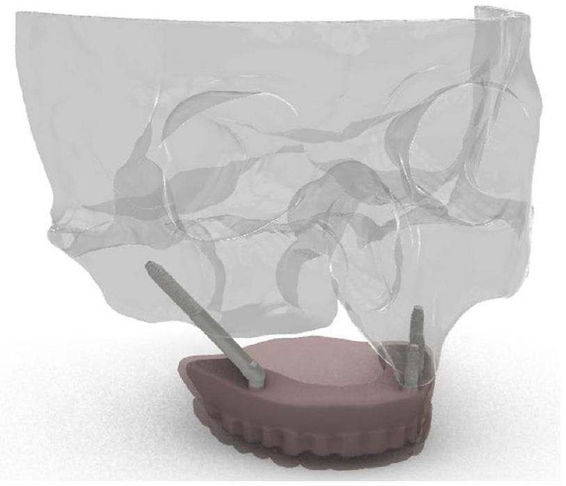
التعديلات اللازمة على النموذج ثلاثي الأبعاد باستخدام SolidWorks (Solidworks 2018، Dassault Systemes Solidworks Corporation. وولثام، ماساتشوستس، الولايات المتحدة الأمريكية)، تم إنشاء إعادة بناء ثلاثية الأبعاد كاملة لهيكل الفك العلوي ودمجها في برنامج ANSYS Workbench لتحليل العناصر المحدودة (الشكل 1).
هيكل الشبكة
| النمذجة | ||
| المادة | معامل يونغ (E) (ميغاباسكال) | نسبة بواسون (v) |
| العظم القشري | 13700 | 0.30 [2، 11] |
| العظم الإسفنجي | 1370 | 0.30 [11] |
|
|
110000 | 0.30 [2] |
| راتنج أكريلي (pmma) | 2700 | 0.30 [2] |
| تيتانيوم | 115000 | 0.35 [2] |
| سبائك Co-Cr | 218000 | 0.33 [27] |
| بورسلين | 82800 | 0.33 [26، 27] |
خصائص المواد
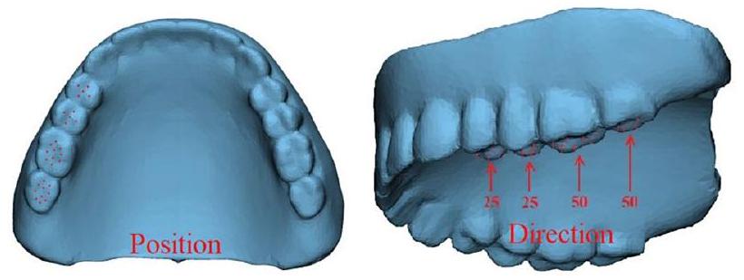
الأحمال وظروف الحدود
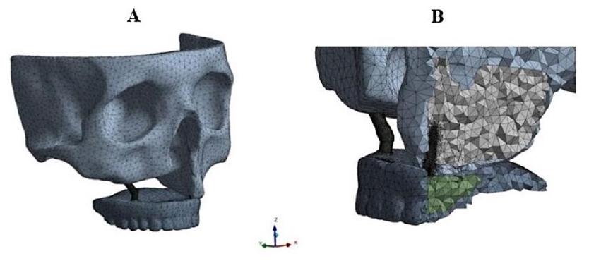
(الشكل 4). تم إجراء تحليلات العناصر المحدودة تحت هذه الظروف والأحمال، مع تسجيل قيم الإجهاد والتشوه القصوى للهيكل الفكي والغرسات. تم فحص النتائج التي تم الحصول عليها بشكل مقارن. يتم عرض توزيع الإجهاد والتشوه للهيكل الفكي بعد التحليل في الشكل 5.
النتائج
فهم أحجام الإجهاد في النموذج والمناطق التي تتركز فيها الإجهادات أمر مهم خلال مراحل التصميم أو اتخاذ القرار. بناءً على ظروف الإجهاد، يمكن للخبراء اتخاذ قرارات مستنيرة بشأن المواد التي سيتم استخدامها أو نوع العلاج، مما يساعد على منع المضاعفات المحتملة وتحسين نتائج المرضى.
عند فحص الشكل 6 لنماذج الغرسات، لوحظ أن أكبر قيمة قصوى للإجهاد الرئيسي تحت جميع شروط الحدود كانت في النموذج 3، بينما كانت أصغر قيمة في النموذج 1 عندما تم استخدام كل من البورسلين
| تفاصيل | اسم/اختصار التفاصيل | التعريف |
| نماذج التحليل | النموذج 1 | غرسة وجنية في الرقم 4 في المنطقة المعيبة وغرسة سنية في الأرقام
|
| النموذج 2 | غرسة وجنية في الرقم 4 في المنطقة المعيبة وغرسة سنية في الأرقام
|
|
| النموذج 3 | غرسة وجنية في الرقم 4 في المناطق المعيبة وغير المعيبة | |
| شروط الحدود | VL-D | تحميل عمودي على المنطقة المعيبة |
| VL-ND | تحميل عمودي على المنطقة غير المعيبة | |
| HL-D | تحميل أفقي على المنطقة المعيبة | |
| HL-ND | تحميل أفقي على المنطقة غير المعيبة | |
| VL-D&ND | تحميل عمودي على المناطق المعيبة وغير المعيبة | |
| HL-D&ND | تحميل أفقي على المناطق المعيبة وغير المعيبة |
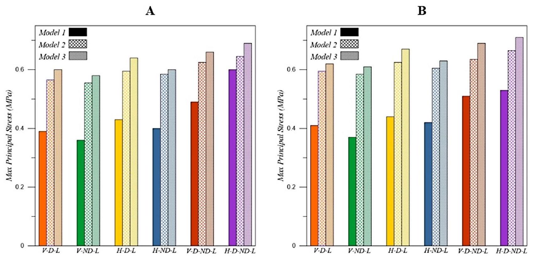
قيمة قصوى للإجهاد الرئيسي تم ملاحظتها تحت شرط تحميل VL-ND (تحميل عمودي على المنطقة غير المعيبة) عبر جميع النماذج. بالإضافة إلى ذلك، فإن استخدام طبقة بورسلين على إطار CoCr كمواد تعويضية قلل قليلاً من قيم الإجهاد مقارنة باستخدام طبقة أكريليك على إطار أكريليك.
عند فحص الشكل 7، يمكن ملاحظة أن قيم أقصى إجهاد فون ميسيس التي تم الحصول عليها في نماذج الغرسات باستخدام كل من طبقة بورسلين على إطار CoCr
وطبقة أكريليك على إطار أكريليك كمواد تعويضية قريبة، وفي بعض الحالات، متطابقة تقريبًا تحت نفس شروط الحدود. على عكس قيم أقصى إجهاد رئيسي، لم تظهر قيم أقصى إجهاد فون ميسيس اختلافات كبيرة تحت شروط الحدود المختلفة، كما لم تظهر اختلافات كبيرة عندما تم تغيير شرط التحميل. علاوة على ذلك، فإن استخدام طبقة أكريليك على إطار أكريليك بدلاً من طبقة بورسلين على إطار CoCr كمواد تعويضية زاد قليلاً من قيم الإجهاد في النماذج.
المناقشة
تم استخدام تحليل العناصر المحدودة في الدراسة الحالية لأنه يمكّن من تقدير قيم الإجهاد بين الغرسة والعظام، كما يسهل نمذجة تصاميم تعويضية متنوعة. تتأثر دقة الاختبارات التي أجريت في دراسات تحليل العناصر المحدودة بخصائص المواد، وتعريفات الواجهة، والهندسة، والقوى المطبقة [11]. وبالتالي، كانت النمذجة في هذه الدراسة تعتمد على بيانات تم الحصول عليها من مسح CT حقيقي. بالإضافة إلى ذلك، لتعكس الظروف الواقعية بشكل أفضل، تم نمذجة الأطراف الاصطناعية السدادية، وتم تطبيق الأحمال مباشرة عليها. تعتبر قيم أقصى إجهاد رئيسي وإجهاد فون ميسيس من المقاييس الأكثر شيوعًا لتقييم توزيع الإجهاد على العظام. يشير أقصى إجهاد رئيسي إلى الإجهاد المركز في منطقة معينة، بينما يسمح قيمة إجهاد فون ميسيس بتقييم خضوع المادة وفشلها [30]. لذلك، تم تقييم كلا قيم الإجهاد في الدراسة الحالية.
عدد الغرسات المستخدمة في الأطراف الاصطناعية المدعومة بالغرسات وموقعها يؤثر بشكل كبير على قيم الإجهاد بين الغرسة والعظام، وكذلك على النجاح العام للأطراف الاصطناعية [31]. في الدراسة الحالية، تم إنشاء ثلاثة نماذج مختلفة، وكشفت أن أعلى قيمة قصوى للإجهاد الرئيسي لوحظت في النموذج 3 (مع غرسة وجنية واحدة موضوعة في كل من المناطق المعيبة وغير المعيبة)، بينما كانت أدنى قيمة في النموذج 1 (مع غرسة وجنية واحدة في المنطقة المعيبة وثلاث غرسات سنية
في المنطقة غير المعيبة). كانت قيم الإجهاد في النموذجين 2 (غرسة وجنية واحدة في المنطقة المعيبة وغرسات سنية اثنتين في المنطقة غير المعيبة) و3 قريبة من بعضها البعض، بينما كانت قيمة الإجهاد في النموذج 1 أقل بكثير من النماذج الأخرى.
على النقيض من ذلك، خطط أكاي وآخرون [2] لثلاثة أطراف اصطناعية مختلفة مدعومة بالغرسات لمواجهة عيوب الفكين من الفئة 4 من أراماني ووجدوا أنه، على عكس هذه الدراسة، فإن استخدام غرسة وجنية في المنطقة غير المعيبة قلل من قيم أقصى إجهاد رئيسي. كما أبلغوا أن استخدام غرسة وجنية في منطقة غير معيبة كان أكثر فائدة من استخدام واحدة أو اثنتين من الغرسات السنية مع وصلات موضعية [2].
حقق وانغ وآخرون [29] في الاحتفاظ الذي توفره المشابك ومقاومة الدعامات لقوى العزم الزائدة من خلال إنشاء نماذج من عيوب الفك العلوي أحادية الجانب باستخدام أطراف اصطناعية تقليدية، وزرع زيجوماتي واحد، وزرعين زيجوماتيين. أشارت نتائج دراستهم إلى أن قيم الإجهاد في النماذج التي تحتوي على زراعات زيجوماتية كانت أقل بكثير من تلك الموجودة في النموذج الذي يحتوي على طرف اصطناعي تقليدي، مع أدنى قيمة إجهاد لوحظت في النموذج الذي يحتوي على زراعتين زيجوماتيتين. واستنتجوا أن الأطراف الاصطناعية المدعومة بزراعات زيجوماتية فعالة لاستعادة عيوب الفك العلوي أحادية الجانب [29].
سجل فريدمان وآخرون [32] قيم إجهاد فون ميس في دراستهم التي تحقق في تأثير دعم العظم السنخي على توزيع الإجهادات لزراعات زيجوماتية وضعت في الوضع الإضافي للجيوب. نتيجة لهذه الدراسة، وجدوا أن الإجهاد كان أقل في النموذج الذي لا يحتوي على عيب في الفك العلوي وأن الدعم الذي قدمه العظم السنخي كان مفيدًا لزراعات زيجوماتية [33]. في الدراسة الحالية، كانت قيم إجهاد فون ميس القصوى التي تم الحصول عليها في نماذج الزرع المختلفة التي تم إنشاؤها تحت نفس ظروف الحدود قريبة من بعضها البعض، وفي بعض الحالات، كانت متساوية تقريبًا.
أفاد كوكماز وآخرون [11] في دراستهم أنهم أنشأوا أربعة نماذج مختلفة من الأطراف الاصطناعية المدعومة بالشريط المدعوم بزراعات زيجوماتية وزراعات سنية في وجود عيب في الفك العلوي أحادي الجانب. وجدوا أن استخدام زراعات زيجوماتية في المنطقة غير المعيبة قلل من قيمة إجهاد فون ميس وأن زيادة عدد الزرعات السنية في المنطقة غير المعيبة لم تقلل من أعلى قيمة إجهاد. في الدراسة الحالية، كانت قيم إجهاد فون ميس في النماذج المعدة باستخدام زراعات زيجوماتية أو أعداد مختلفة من الزرعات السنية في المنطقة غير المعيبة قريبة من بعضها البعض، حتى عند تغيير اتجاه القوة المطبقة والمنطقة التي تم تطبيقها فيها.
تم الإبلاغ عن أقصى قوة عض في المرضى الذين لديهم زراعات متكاملة عظمياً بمقدار 144.4 نيوتن [34]. لذلك، في العديد من الدراسات، تم تطبيق قوة مقدارها 150 نيوتن لمحاكاة أقصى قوة عض فعلية [2، 11، 29].
في الدراسة الحالية، عند تقييمها وفقًا للقوى المطبقة على النماذج، لوحظت أعلى قيمة إجهاد رئيسي قصوى عندما تم تطبيق القوة الأفقية في نفس الوقت على المناطق المعيبة وغير المعيبة، بينما لوحظت أدنى قيمة عندما تم تطبيق القوة الرأسية على المنطقة غير المعيبة. بالإضافة إلى ذلك، عندما تم تغيير ظروف التحميل في النماذج، لم تظهر قيم إجهاد فون ميس القصوى التي تم الحصول عليها اختلافات كبيرة، مشابهة لقيم الإجهاد الرئيسي القصوى. على عكس هذه الدراسة، وجد كوكماز وآخرون [11] أدنى قيمة لإجهاد فون ميس في النماذج التي وضعوا فيها زراعات زيجوماتية وزراعات سنية في المنطقة غير المعيبة عندما تم تطبيق القوة الرأسية على تلك المنطقة. كما وجدوا قيمًا مشابهة في النماذج التي تم فيها تطبيق القوة الرأسية بشكل منفصل على المناطق المعيبة وغير المعيبة في النموذج الذي طبقوا فيه زراعات سنية فقط على المنطقة غير المعيبة، بينما وجدوا قيم إجهاد فون ميس أعلى عندما طبقوا القوة الرأسية في نفس الوقت على كل من المناطق المعيبة وغير المعيبة [11].
وجد أكاي وآخرون [2] أعلى قيمة إجهاد عندما تم تطبيق القوة على كلا الجانبين في النموذج الذي تم فيه وضع زرع سن واحد في المنطقة غير المعيبة، بينما تم العثور على أدنى قيمة إجهاد في النموذج الذي تم فيه وضع زرع زيجوماتي واحد في المنطقة غير المعيبة. أفادوا أن توزيع الإجهادات على الأطراف الاصطناعية يمكن أن يكون أكثر عقلانية بمساعدة زراعات زيجوماتية، والتي يمكن أن توزع الإجهادات على كل جزء من الفك العلوي [2].
طبق فارغيس وآخرون [3] نوعين من طرق العلاج في نموذج فك علوي خالٍ من الأسنان شديد الضمور. في النموذج الأول، تم وضع زرع تقليدي وزرع زيجوماتي في كل ربع، بينما في النموذج الثاني، تم وضع زراعتين زيجوماتيتين بشكل ثنائي في كل ربع. تم تطبيق قوة رأسية مقدارها 150 نيوتن، وقوة جانبية مقدارها 50 نيوتن، وقوة إطباقية مقدارها 300 نيوتن على النماذج. عند تطبيق القوة الرأسية، تم توزيع الإجهاد بشكل أوسع في النموذج الذي يحتوي على زراعات تقليدية. ومع ذلك، عند تطبيق القوة الجانبية، تم تحديد إجهاد أعلى بكثير في النموذج الذي يحتوي على زراعات تقليدية مقارنة بالنموذج الآخر. عندما تم تطبيق القوى الرأسية والجانبية في نفس الوقت، تم العثور على أعلى قيمة لإجهاد فون ميس في النموذج الذي يحتوي على أربع زراعات زيجوماتية. في الدراسة الحالية، تم العثور على أعلى قيمة إجهاد رئيسي قصوى في النموذج الذي يحتوي على زراعات زيجوماتية وضعت في المنطقة غير المعيبة عندما تم تطبيق القوة الأفقية في نفس الوقت على كل من المناطق المعيبة وغير المعيبة. على الرغم من أن قيمة فون ميس لم تكن مختلفة بشكل كبير
بين النماذج، إلا أنها كانت أعلى قليلاً في هذا النموذج.
بعد وضع الزرع، يمكن تطبيق ترميمات اصطناعية مختلفة، مثل الخيارات المدعومة بإطار معدني أو أكريليك بالكامل، للأطراف الاصطناعية المؤقتة أو النهائية [35]. قد تكون مواد الإطار عاملاً مهمًا في نقل الإجهاد إلى منطقة اتصال الزرع بالعظم [36]. بالإضافة إلى ذلك، أظهرت استخدام ترميمات اصطناعية أكريليك بالكامل أكبر مشاكل في طب الأسنان، مثل الكسور في الطرف الاصطناعي [35]. في دراسة سابقة، تم مقارنة توزيع الإجهادات في الأطر في مفاهيم طب الأسنان المختلفة (All-on-4 وAll-on-6) باستخدام دراسة FEA ثلاثية الأبعاد. واستنتجوا أن المواد الأكثر صلابة (CoCr وZr) قللت من مستويات الإجهاد في مناطق مختلفة وأظهرت سلوكًا بيوميكانيكيًا الأكثر ملاءمة. علاوة على ذلك، أشاروا إلى أن إطار التيتانيوم كان أداؤه ضعيفًا في مفهوم الأطراف الاصطناعية All-on-4 [36، 37]. في الدراسة الحالية، أدى استخدام طرف اصطناعي مصنوع باستخدام طبقة أكريليك على إطار أكريليك بدلاً من طرف اصطناعي مصنوع باستخدام طبقة بورسلين على
هناك بعض القيود في هذه الدراسة. أولاً، لم يتم تطبيق قوى العضلات أثناء تطبيق القوى الرأسية والأفقية. كان من الممكن أن يتم عكس القوة أثناء المضغ بشكل أكثر واقعية من خلال دمج قوى العضلات. ثانيًا، تم افتراض أن جميع الزرعات كانت
الاستنتاجات
تم الحصول على أعلى قيمة للضغط الرئيسي الأقصى عندما تم تطبيق قوة أفقية في نفس الوقت على كل من المناطق المعيبة وغير المعيبة، بينما تم العثور على أدنى قيمة عندما تم تطبيق قوة عمودية على المنطقة غير المعيبة. عندما كانت كلتا طبقتي البورسلين على
شكر وتقدير
مساهمات المؤلفين
تمويل
توفر البيانات
الإعلانات
الموافقة الأخلاقية والموافقة على المشاركة
أخلاقيات الإنسان
موافقة على النشر
المصالح المتنافسة
تفاصيل المؤلف
نُشر على الإنترنت: 19 يناير 2025
References
- Özdemir H, Hülagü B. Three-dimensional Finite Element Analysis of Zygoma Implants in a patient with a Maxillary defect. Int J Innovative Res Reviews. 2024;8(1):6-11.
- Akay C, Yaluğ S. Biomechanical 3-dimensional finite element analysis of obturator protheses retained with zygomatic and dental implants in maxillary defects. Med Sci Monitor: Int Med J Experimental Clin Res. 2015;21:604. https://doi.org/10.12659/MSM.892680.
- Varghese KG, Kurian N, Gandhi N, Gandhi S, Daniel AY, Thomas HA et al. Three-dimensional finite element analysis of zygomatic implants for rehabilitation of patients with a severely atrophic maxilla. The Journal of Prosthetic Dentistry, 2023; 129(4): 597. e1-597. https://doi.org/10.1016/j.prosdent.2023.0 1.012
- Tezerişener HA, Özalp Ö, Altay MA, Sindel A. Comparison of stress distribution around all-on-four implants of different angulations and zygoma implants: a 7-model finite element analysis. BMC Oral Health. 2024;24(1):176. https://doi. org/10.1186/s12903-023-03761-x.
- Gracher AHP, Moura MB, Peres PS, Thome G, Padovan LEM, Trojan LC. Full arch rehabilitation in patients with atrophic upper jaws with zygomatic implants: a systematic review. Int J Implant Dentistry. 2021;7:1-9. https://doi.org/10.118 6/s40729-021-00297-z.
- Corvello PC, Montagner A, Batista FC, Smidt R, Shinkai RS. Length of the drilling holes of zygomatic implants inserted with the standard technique or a revised method: a comparative study in dry skulls. J Cranio-Maxillofacial Surg. 2011;39(2):119-23.
- Petrungaro PS, Gonzales S, Villegas C, Yousef J, Arango A. A retrospective study of a Multi-center Case Series of 452 zygomatic implants placed over 5 years for treatment of severe Maxillary Atrophy. Compendium. 2020;41(4):232.
- Schmidt BL, Pogrel MA, Young CW, Sharma A. Reconstruction of extensive maxillary defects using zygomaticus implants. J Oral Maxillofac Surg. 2004;62:82-9. https://doi.org/10.1016/j.joms.2004.06.027.
- Parel SM, Branemark P, Ohrnell LO, Svensson B. Remote implant anchorage for the rehabilitation of maxillary defects. J Prosthet Dent. 2001;86(4):377-81. https://doi.org/10.1067/mpr.2001.118874.
- Kreissl ME, Heydecke G, Metzger MC, Schoen R. Zygoma implant-supported prosthetic rehabilitation after partial maxillectomy using surgical navigation: a clinical report. J Prosthet Dent. 2007;97(3):121-8. https://doi.org/10.1016/j.p rosdent.2007.01.009.
- Korkmaz FM, Korkmaz YT, Yaluğ S, Korkmaz T. Impact of dental and zygomatic implants on stress distribution in maxillary defects: a 3-dimensional finite element analysis study. J Oral Implantology. 2012;38(5):557-67. https://doi.or g/10.1563/AAID-JOI-D-10-00111.
- Rathod DK, Chakravarthy C. Stress distribution of the zygomatic implants in post-mucormycosis case: a finite element analysis. J Oral Maxillofac Surg. 2023;22(3):695-701.
- Logan DL. A first course in the finite element method. Evelyn Veitch, Harlan James. Univ Wisconsin-Platteville Thomson 4. 2011.
- Uzun Yaylacı E, Özdemir ME, Güvercin Y, Öztürk Ş, Yaylacı M. Analysis of the mechano-bactericidal effects of nanopatterned surfaces on implant-derived bacteria using the FEM. 2023; 567-77. https://doi.org/10.12989/anr.2023.15.6. 567
- Uzun Yaylaci E, Yaylaci M, Özdemir ME, Terzi M, Öztürk Ş. Analyzing the mechano-bactericidal effect of nano-patterned surfaces by finite element method and verification with artificial neural networks. Adv nano Res. 2023;15(2):165-74.
- Güvercin Y, Abdioğlu AA, Dizdar A, Uzun Yaylacı E, Yaylacı M. Suture button fixation method used in the treatment of syndesmosis injury: a biomechanical analysis of the effect of the placement of the button on the distal tibiofibular joint in the mid-stance phase with finite elements method. Injury. 2022;53(7):2437-45. https://doi.org/10.1016/j.injury.2022.05.037.
- Güvercin Y, Yaylacı M, Dizdar A, Kanat A, Uzun Yaylacı E, Ay S, et al. Biomechanical analysis of odontoid and transverse atlantal ligament in humans with ponticulus posticus variation under different loading conditions: finite element study. Injury. 2022;53(12):3879-86. https://doi.org/10.1016/j.injury. 20 22.10.003.
- Güvercin Y, Yaylacı M, Ölmez H, Özdemir ME, Dizdar A, Uzun Yaylacı E. Finite element analysis of the mechanical behavior of the different angle hip femoral stem. 2022;29-46. https://doi.org/10.12989/bme.2022.6.1.029
- Zagane MES, Abdelmadjid M, Yaylacı M, Abderahmen S, Uzun Yaylacı E. Finite element analysis of the femur fracture for a different total hip prosthesis (Charnley, Osteal, and Thompson). Structural Engineering and Mechanics, An Int’l Journal, 2023; 88(6):583-588. https://doi.org/10.12989/sem.2023.88.6.583
- Moulgada A, Zagane MES, Yaylacı M, Djafar AK, Abderahmane S, Öztürk Ş, et al. Comparative study by the finite element method of three activities of a wearer of total hip prosthesis during the postoperative period. Struct Eng Mech Int’l J. 2023;87(6):575-83. https://doi.org/10.12989/sem.2023.87.6.575.
- Benouis A, Zagane MES, Moulgada A, Yaylacı M, Kaci DA, Terzi M, et al. Finite element analysis of the behavior of elliptical cracks emanating from the orthopedic cement interface in total hip prostheses. Struct Eng Mech. 2024;89(5):539. https://doi.org/10.12989/sem.2024.89.8.539.
- Nişanci GN, Güvercin Y, Ateş SM, Ölmez H, Uzun Yaylacı E, Yaylacı M. Investigation of the effect of different prosthesis designs and numbers on stress, strain and deformation distribution. Int J Eng Appl Sci. 2020;12(4):138-52. https://d oi.org/10.24107/ijeas.816227.
- Terzi M, Güvercin Y, Ateş SM, Sekban DM, Yaylacı M. Effect of different abutment materials on stress distribution in peripheral bone and dental implant system. Sigma J Eng Nat Sci. 2020;38(3):1495-507.
- Kurt A, Yaylacı M, Dizdar A, Naralan ME, Yaylacı EU, Öztürk Ş, et al. Evaluation of the effect on the permanent tooth germ and the adjacent teeth by finite element impact analysis in the traumatized primary tooth. Int J Pediatr Dent. 2024. https://doi.org/10.1111/ipd.13183.
- Over LM, Eric D. Interdisciplinary prosthetic rehabilitation following bilateral maxillectomy with total upper lip and unilateral zygoma resection: a clinical report. J Prosthet Dent. 2022;131:341-5. https://doi.org/10.1016/j.prosdent. 20 22.03.038.
- Elias A, Banu RF, Vaidyanathan AK, Padmanabhan TV. A comparative finite element analysis of titanium, poly-ether-etherketone, and zirconia abutment on stress distribution around maxillary anterior implants. Dent Res J (Isfahan). 2024;6:21. PMID: 38807658; PMCID: PMC11132231.
- Tekin
, Değer , Demirci F. Evaluation of the use of PEEK material in implantsupported fixed restorations by finite element analysis. Niger J Clin Pract. 2019;22(9):1252-8. https://doi.org/10.4103/njcp.njcp_144_19. - Akay C, Yaluğ S, Dalkız M. Effects of dental and zygomatic implants on stress distribution in zygomatic bone. Suleyman Demirel Univ J Eng Sci Des. 2014;2(3):253-9. SI:BioMechanics.
- Wang M, Qu X, Cao M, Wang D, Zhang C. Biomechanical three-dimensional finite element analysis of prostheses retained with/without zygoma implants in maxillectomy patients. J Biomech. 2013;46(6):1155-61. https://doi.org/10.1 016/j.jbiomech.2013.01.004.
- Yemineni BC, Mahendra J, Nasina J, Mahendra L, Shivasubramanian L, Perika SB. Evaluation of maximum principal stress, Von mises stress, and deformation on surrounding mandibular bone during insertion of an implant: a three-dimensional finite element study. Cureus. 2020;12(7):e9430. https://doi. org/10.7759/cureus.9430.
- Geng JP, Tan KB, Liu GR. Application of finite element analysis in implant dentistry: a review of the literature. J Prosthet Dent. 2001;85(6):585-98. https:/ /doi.org/10.1067/mpr.2001.115251.
- Freedman M, Ring M, Stassen LFA. Effect of alveolar bone support on zygomatic implants in an extra-sinus position-a finite element analysis study. Int J Oral Maxillofac Surg. 2015;44(6):785-90. https://doi.org/10.1016/j.ijom.2015. 01.009.
- Freedman M, Ring M, Stassen LFA. Effect of alveolar bone support on zygomatic implants: a finite element analysis study. Int J Oral Maxillofac Surg. 2013;42(5):671-6. https://doi.org/10.1016/j.jjom.2012.12.006.
- Haraldson T, Carlsson GE. Bite force and oral function in patients with osseointegrated oral implants. Eur J Oral Sci. 1977;85(3):200-8. https://doi.org/10.1 111/j.1600-0722.1977.tb00554.x.
- Agliardi E, Romeo D, Panigatti S, Nobre MA, Malo P. Immediate full-arch rehabilitation of the severely atrophic maxilla supported by zygomatic implants: a prospective clinical study with minimum follow-up of 6 years. Int J Oral Maxillofac Surg. 2017;46(12):1592-9. https://doi.org/10.1016/j.jjom.2017.05.023.
- Bacchi A, Consani RLX, Mesquita MF, Dos Santos MBF. Effect of framework material and vertical misfit on stress distribution in implant-supported partial prosthesis under load application: 3-D finite element analysis. Acta Odontol Scand. 2013;71(5):1243-9. https://doi.org/10.3109/00016357.2012.757644.
- Bhering CLB, Mesquita MF, Kemmoku DT, Noritomi PY, Consani RLX, Barao VAR. Comparison between all-on-four and all-on-six treatment concepts and framework material on stress distribution in atrophic maxilla: a prototyping guided 3D-FEA study. Mater Sci Engineering: C. 2016;69:715-25. https://doi.o rg/10.1016/j.msec.2016.07.059.
- Arinc H. Implant-supported fixed partial prostheses with different prosthetic materials: a three-dimensional finite element stress analysis. Implant Dent. 2018;27(3):303-10. https://doi.org/10.1097/ID.0000000000000750.
ملاحظة الناشر
- VL؛ تحميل عمودي، HL؛ تحميل أفقي، D؛ منطقة معيبة، ND؛ منطقة غير معيبة
DOI: https://doi.org/10.1186/s12903-025-05468-7
PMID: https://pubmed.ncbi.nlm.nih.gov/39828680
Publication Date: 2025-01-19
Evaluation of prostheses retained zygomatic and dental implants in large defects in the maxilla due to tumors or major trauma by biomechanical 3-dimensional finite element analysis
Abstract
Background Zygomatic implants are becoming an ideal treatment approach for implant-supported prosthesis treatment developed for the atrophic maxilla. This study aims to evaluate the amount and distribution of stress in implants and peri-implant bone using different implant-supported prosthesis configurations in Aramany Class I maxillary defects through 3 -dimensional finite element analysis. Methods A 3-dimensional finite element model of the Aramany class I defect was created. Three different implantsupported prostheses were modelled: model 1:1 zygomatic implant and 3 dental implants, model 2: 1 zygomatic implant and 2 dental implants, and model 3: 2 zygomatic implants. Vertical and horizontal loads of 150 N were applied in 6 different ways to the defected and non-defective areas. Maximum principal stress and von mises stresses in the bone surrounding the implants were evaluated. Results When all loading conditions were evaluated with both porcelain layer on Co-Cr framework and acrylic layer on acrylic framework, the highest maximum principal stress value was observed in Model 3. In contrast, the lowest value was observed in Model 1. The highest maximum principal stress occurred when a horizontal load was applied simultaneously to both the defective and non-defective areas. In contrast, the lowest value was observed when a vertical load was applied to the non-defective area. The von Mises stress values were found to be similar across all models when both restoration materials were used. Conclusions Based on the results of this study, it can be concluded that increasing the number of implants in the non-defective area reduces the highest stress value while using acrylic as a restoration material slightly increases the stress value.
Background
Schmidt et al. [8], reported that the combination of zygomatic and standard endosseous implants can provide retention and support for maxillary obturator prostheses following extensive resection of the maxilla. As a result of the predictable implant support and retention provided, the planning of implant-supported obturator prostheses has become an effective treatment method [8-10]. However, the design of the dental superstructure significantly affects the loading of dental implants and bone deformation. This deformation can lead to excessive stress accumulation in the bone surrounding the implants, resulting in bone resorption and potential implant failure [11].
The transfer of load and distribution of stress in the implant-bone connection area are critical factors affecting the success rate of implants. Direct clinical evaluation is necessary to assess the biomechanical response of an implant to the surrounding bone. However, this is often impractical due to complex structures, lengthy operating times, and ethical concerns. Consequently, in vitro methods such as strain gauges, analytical techniques, experimental approaches, computational models, and finite element analysis (FEA) have been employed to evaluate the biomechanical behaviour of dental implants. Each of these methods has its advantages and limitations. However, FEA is indispensable for analysing situations involving numerous complex geometries and various implant configurations [3]. FEA is an effective computational tool adapted from the engineering field for dental implant biomechanics, allowing for the evaluation of stress [12]. FEA divides a complex body into smaller components
that can be modelled separately using mathematical equations [13]. FEA is widely used to assess the biomechanical performance of various dental implant designs and their effects on clinical factors related to implant success [2]. With FEA, both the stress distribution on implants and abutments and the stress distribution in the bone supporting these implants can be evaluated [12].
This study aimed to evaluate the amount and distribution of stress in implants and peri-implant bone in prosthetic models designed with different configurations of zygomatic and dental implants for Aramany Class I maxillary defects. Additionally, the study aimed to understand the prognosis of these treatment options using FEA.
Methods
In this study, the ANSYS Workbench software package (ANSYS 16.0, Swanson Analysis Systems Inc., Houston PA, USA) was utilized for numerical modelling and finite element analysis of the physical problem. To conduct a finite element analysis of an existing dental issue, an accurate numerical model must first be created. During this stage, the most appropriate geometry for the numerical model is developed, and the most suitable finite elements are selected to form the mesh structure. Choosing the right finite element geometry and size is crucial for the accuracy of the results. The mesh structure is constructed using the selected finite elements (geometry and mesh structure). The material properties for the created mesh structure are then defined (material properties). Finally, finite element analysis is performed based on the specified boundary conditions and loading scenarios (loads and boundary conditions).
Geometry
necessary adjustments to the 3D model using SolidWorks (Solidworks 2018, Dassault Systemes Solidworks Corporation. Waltham MA, USA.), a complete 3D reconstruction of the maxillary structure was created and integrated into the ANSYS Workbench program for finite element analysis (Fig. 1).
Mesh structure
| modelling | ||
| Material | Young’s modulus (E) (MPa) | Poisson’s ratio (v) |
| Cortical bone | 13,700 | 0.30 [2, 11] |
| Trabecular bone | 1370 | 0.30 [11] |
|
|
110,000 | 0.30 [2] |
| Acrylic resin (pmma) | 2700 | 0.30 [2] |
| Titanium | 115,000 | 0.35 [2] |
| Co-Cr Alloy | 218,000 | 0.33 [27] |
| Porcelain | 82,800 | 0.33 [26, 27] |
Material properties
Loads and boundary conditions
(Fig. 4). Finite element analyses were performed under these conditions and loadings, with maximum stress and deformation values for the maxillary structure and implants recorded. The results obtained were examined comparatively. The stress and deformation distribution of the maxillary structure following the analysis is shown in Fig. 5.
Results
Understanding the stress magnitudes in the model and the regions where stresses are concentrated is significant during the design or decision-making phases. Based on the stress conditions, experts can make informed decisions regarding the materials to be used or the type of treatment, helping to prevent potential complications and improve patient outcomes.
When examining Fig. 6 for the implant models, the greatest maximum principal stress value under all boundary conditions was observed in Model 3, while the smallest value was found in Model 1 when both porcelain
| Detail | Detail Name/Abbreviation | Definition |
| Analysis Models | Model 1 | Zygoma implant at number 4 in the defective area and dental implant at numbers
|
| Model 2 | Zygoma implant at number 4 in the defective area and dental implant at numbers
|
|
| Model 3 | Zygoma implant at number 4 in the defective and non-defective areas | |
| Boundary Conditions | VL-D | Vertical loading on the defective area |
| VL-ND | Vertical loading on the non-defective area | |
| HL-D | Horizontal loading on the defective area | |
| HL-ND | Horizontal loading on the non-defective area | |
| VL-D&ND | Vertical loading on the defective and non-defective areas | |
| HL-D&ND | Horizontal loading on the defective and non-defective areas |
maximum principal stress value was noted under the VL-ND (vertical loading on the non-defective area) loading condition across all models. Additionally, using porcelain layer on CoCr framework as a prosthetic material slightly decreased the stress values compared to using acrylic layer on acrylic framework.
When examining Fig. 7, it can be observed that the maximum von Mises stress values obtained in the implant models using both porcelain layer on CoCr
framework and acrylic layer on acrylic framework as prosthetic materials are close and, in some cases, nearly identical under the same boundary conditions. Unlike the maximum principal stress values, the maximum von Mises stress values did not exhibit significant differences under different boundary conditions, nor did they show substantial variations when the loading condition was altered. Furthermore, using acrylic layer on acrylic framework instead of porcelain layer on CoCr framework as the prosthetic material slightly increased the stress values in the models.
Discussion
FEA was employed in the current study because it enables the estimation of stress values between the implant and the bone, while also facilitating the modelling of various prosthetic designs. The accuracy of the tests conducted in FEA studies is influenced by the properties of the materials, interface definitions, geometries, and applied forces [11]. Consequently, the modelling in this study was based on data obtained from a real CT scan. Additionally, to better reflect real-world conditions, the obturator prosthesis was modelled, and loads were applied directly to it. The maximum principal stress and von Mises stress values are the most commonly used metrics for evaluating stress distribution on bone. The maximum principal stress indicates the stress concentrated in a specific region, while the von Mises stress value allows for the assessment of material yielding and failure [30]. Therefore, both stress values were evaluated in the current study.
The number of implants used in implant-supported prostheses and their placement significantly affect the stress values between the implant and the bone, as well as the overall success of the prosthesis [31]. In the present study, three different models were created, revealing that the highest maximum principal stress value was observed in Model 3 (with one zygomatic implant placed in both the defected and non-defective areas), while the lowest value was found in Model 1 (with one zygomatic implant in the defected area and three dental implants
in the non-defective area). The stress values in Models 2 (one zygomatic implant in the defected area and two dental implants in the non-defective area) and 3 were close to each other, whereas the stress value in Model 1 was considerably lower than in the other two models.
In contrast, Akay et al. [2] planned three different implant-supported locator attachment prostheses for Aramany Class 4 maxillary defects and found that, unlike this study, the use of a zygomatic implant in the non-defective area reduced the maximum principal stress values. They also reported that using a zygomatic implant in a non-defective area was more advantageous than employing one or two dental implants with locator attachments [2].
Wang et al. [29] investigated the retention provided by clasps and the resistance of abutments to excessive torque forces by creating models of unilateral maxillary defects using a conventional prosthesis, one zygomatic implant, and two zygomatic implants. The results of their study indicated that the stress values in the models with zygomatic implants were significantly lower than those in the model with a conventional prosthesis, with the lowest stress value observed in the model featuring two zygomatic implants. They concluded that zygomatic implantsupported prostheses are effective for the restoration of unilateral maxillary defects [29].
Freedman et al. [32] recorded von Mises stress values in their study investigating the effect of alveolar bone support on the stress distribution of zygomatic implants placed in the extra-sinus position. As a result of this study, they found that less stress occurred in the model without a maxillary defect and that the support provided by the alveolar bone was beneficial for zygomatic implants [33]. In the present study, the maximum von Mises stress values obtained in different implant models created under the same boundary conditions were found to be close to each other and, in some cases, almost equal.
Korkmaz et al. [11] reported in their study that they created four different bar-retained prosthesis models supported by zygomatic and dental implants in the presence of a unilateral maxillary defect. They found that the use of zygomatic implants in the non-defective area reduced the von Mises stress value and that increasing the number of dental implants in the non-defective area did not reduce the highest stress value. In the present study, the von Mises stress values in models prepared using zygomatic implants or different numbers of dental implants in the non-defective area were found to be close to each other, even when the direction of the applied force and the area where it was applied was changed.
The maximum bite force in patients with osseointegrated implants has been reported as 144.4 N [34]. Therefore, in many studies, a force of 150 N has been applied to simulate the actual maximum bite force [2, 11, 29].
In the present study, when evaluated according to the forces applied to the models, the highest maximum principal stress value was observed when horizontal force was applied simultaneously to the defected and non-defective areas, while the lowest value was observed when vertical force was applied to the non-defective area. Additionally, when the loading conditions were changed in the models, the maximum von Mises stress values obtained did not show significant differences, similar to the maximum principal stress values. Unlike this study, Korkmaz et al. [11] found the lowest von Mises stress value in models where they placed zygomatic and dental implants in the non-defective area when vertical force was applied to that area. They also found similar values in models where vertical force was applied separately to the defected and non-defective areas in the model where they applied only dental implants to the non-defective area, while they found higher von Mises stress values when they applied vertical force simultaneously to both the defected and non-defective areas [11].
Akay et al. [2] found the highest stress value when force was applied to both sides in the model where one dental implant was placed in the non-defective area, while the lowest stress value was found in the model where one zygomatic implant was placed in the non-defective area. They reported that the distribution of stresses on the prostheses could be more rational with the help of zygomatic implants, which could distribute the stresses to each part of the maxilla [2].
Varghese et al. [3] applied two types of treatment methods in a severely atrophic edentulous maxilla model. In the first model, one conventional and one zygomatic implant was placed in each quadrant, while in the second model, two zygomatic implants were placed bilaterally in each quadrant. A vertical force of 150 N , a lateral force of 50 N , and an occlusal force of 300 N were applied to the models. When vertical force was applied, the stress was distributed more widely in the model with conventional implants. However, when lateral force was applied, significantly higher stress was determined in the model with conventional implants compared to the other model. When vertical and lateral forces were applied simultaneously, the highest von Mises stress value was found in the model with four zygomatic implants. In the present study, the highest maximum principal stress value in the model with zygomatic implants placed in the non-defective area was found when horizontal force was applied simultaneously to both the defected and non-defective areas. Although the von Mises value was not significantly
different among the models, it was slightly higher in this model.
After implant placement, different prosthetic restorations, such as all-acrylic and metal framework-supported options, can be applied for temporary or final prostheses [35]. The framework materials may be an important factor in stress transmission to the implant-bone connection area [36]. Additionally, using all-acrylic prosthetic restorations has shown the most prosthodontic problems, such as fractures in the prosthesis [35]. In a previous study, the stress distribution of frameworks in different prosthodontic concepts (All-on-4 and All-on-6) was compared using a 3D FEA study. They concluded that stiffer framework materials ( CoCr and Zr ) decreased stress levels in different areas and exhibited the most suitable biomechanical behaviour. Furthermore, they noted that the titanium framework performed poorly in the All-on- 4 prosthesis concept [36, 37]. In the present study, the use of a prosthesis made using an acrylic layer on acrylic framework instead of a prosthesis made using porcelain layer on
There are some limitations to this study. First, muscle forces were not applied while vertical and horizontal forces were applied. The force during chewing could have been reflected more realistically by incorporating muscle forces. Second, all implants were assumed to be
Conclusions
the highest maximum principal stress value was obtained when horizontal force was applied simultaneously to both the defected and non-defective areas, while the lowest value was found when vertical force was applied to the non-defective area. When both porcelain layer on
Acknowledgements
Author contributions
Funding
Data availability
Declarations
Ethical approval and consent to participate
Human ethics
Consent for publication
Competing interests
Author details
Published online: 19 January 2025
References
- Özdemir H, Hülagü B. Three-dimensional Finite Element Analysis of Zygoma Implants in a patient with a Maxillary defect. Int J Innovative Res Reviews. 2024;8(1):6-11.
- Akay C, Yaluğ S. Biomechanical 3-dimensional finite element analysis of obturator protheses retained with zygomatic and dental implants in maxillary defects. Med Sci Monitor: Int Med J Experimental Clin Res. 2015;21:604. https://doi.org/10.12659/MSM.892680.
- Varghese KG, Kurian N, Gandhi N, Gandhi S, Daniel AY, Thomas HA et al. Three-dimensional finite element analysis of zygomatic implants for rehabilitation of patients with a severely atrophic maxilla. The Journal of Prosthetic Dentistry, 2023; 129(4): 597. e1-597. https://doi.org/10.1016/j.prosdent.2023.0 1.012
- Tezerişener HA, Özalp Ö, Altay MA, Sindel A. Comparison of stress distribution around all-on-four implants of different angulations and zygoma implants: a 7-model finite element analysis. BMC Oral Health. 2024;24(1):176. https://doi. org/10.1186/s12903-023-03761-x.
- Gracher AHP, Moura MB, Peres PS, Thome G, Padovan LEM, Trojan LC. Full arch rehabilitation in patients with atrophic upper jaws with zygomatic implants: a systematic review. Int J Implant Dentistry. 2021;7:1-9. https://doi.org/10.118 6/s40729-021-00297-z.
- Corvello PC, Montagner A, Batista FC, Smidt R, Shinkai RS. Length of the drilling holes of zygomatic implants inserted with the standard technique or a revised method: a comparative study in dry skulls. J Cranio-Maxillofacial Surg. 2011;39(2):119-23.
- Petrungaro PS, Gonzales S, Villegas C, Yousef J, Arango A. A retrospective study of a Multi-center Case Series of 452 zygomatic implants placed over 5 years for treatment of severe Maxillary Atrophy. Compendium. 2020;41(4):232.
- Schmidt BL, Pogrel MA, Young CW, Sharma A. Reconstruction of extensive maxillary defects using zygomaticus implants. J Oral Maxillofac Surg. 2004;62:82-9. https://doi.org/10.1016/j.joms.2004.06.027.
- Parel SM, Branemark P, Ohrnell LO, Svensson B. Remote implant anchorage for the rehabilitation of maxillary defects. J Prosthet Dent. 2001;86(4):377-81. https://doi.org/10.1067/mpr.2001.118874.
- Kreissl ME, Heydecke G, Metzger MC, Schoen R. Zygoma implant-supported prosthetic rehabilitation after partial maxillectomy using surgical navigation: a clinical report. J Prosthet Dent. 2007;97(3):121-8. https://doi.org/10.1016/j.p rosdent.2007.01.009.
- Korkmaz FM, Korkmaz YT, Yaluğ S, Korkmaz T. Impact of dental and zygomatic implants on stress distribution in maxillary defects: a 3-dimensional finite element analysis study. J Oral Implantology. 2012;38(5):557-67. https://doi.or g/10.1563/AAID-JOI-D-10-00111.
- Rathod DK, Chakravarthy C. Stress distribution of the zygomatic implants in post-mucormycosis case: a finite element analysis. J Oral Maxillofac Surg. 2023;22(3):695-701.
- Logan DL. A first course in the finite element method. Evelyn Veitch, Harlan James. Univ Wisconsin-Platteville Thomson 4. 2011.
- Uzun Yaylacı E, Özdemir ME, Güvercin Y, Öztürk Ş, Yaylacı M. Analysis of the mechano-bactericidal effects of nanopatterned surfaces on implant-derived bacteria using the FEM. 2023; 567-77. https://doi.org/10.12989/anr.2023.15.6. 567
- Uzun Yaylaci E, Yaylaci M, Özdemir ME, Terzi M, Öztürk Ş. Analyzing the mechano-bactericidal effect of nano-patterned surfaces by finite element method and verification with artificial neural networks. Adv nano Res. 2023;15(2):165-74.
- Güvercin Y, Abdioğlu AA, Dizdar A, Uzun Yaylacı E, Yaylacı M. Suture button fixation method used in the treatment of syndesmosis injury: a biomechanical analysis of the effect of the placement of the button on the distal tibiofibular joint in the mid-stance phase with finite elements method. Injury. 2022;53(7):2437-45. https://doi.org/10.1016/j.injury.2022.05.037.
- Güvercin Y, Yaylacı M, Dizdar A, Kanat A, Uzun Yaylacı E, Ay S, et al. Biomechanical analysis of odontoid and transverse atlantal ligament in humans with ponticulus posticus variation under different loading conditions: finite element study. Injury. 2022;53(12):3879-86. https://doi.org/10.1016/j.injury. 20 22.10.003.
- Güvercin Y, Yaylacı M, Ölmez H, Özdemir ME, Dizdar A, Uzun Yaylacı E. Finite element analysis of the mechanical behavior of the different angle hip femoral stem. 2022;29-46. https://doi.org/10.12989/bme.2022.6.1.029
- Zagane MES, Abdelmadjid M, Yaylacı M, Abderahmen S, Uzun Yaylacı E. Finite element analysis of the femur fracture for a different total hip prosthesis (Charnley, Osteal, and Thompson). Structural Engineering and Mechanics, An Int’l Journal, 2023; 88(6):583-588. https://doi.org/10.12989/sem.2023.88.6.583
- Moulgada A, Zagane MES, Yaylacı M, Djafar AK, Abderahmane S, Öztürk Ş, et al. Comparative study by the finite element method of three activities of a wearer of total hip prosthesis during the postoperative period. Struct Eng Mech Int’l J. 2023;87(6):575-83. https://doi.org/10.12989/sem.2023.87.6.575.
- Benouis A, Zagane MES, Moulgada A, Yaylacı M, Kaci DA, Terzi M, et al. Finite element analysis of the behavior of elliptical cracks emanating from the orthopedic cement interface in total hip prostheses. Struct Eng Mech. 2024;89(5):539. https://doi.org/10.12989/sem.2024.89.8.539.
- Nişanci GN, Güvercin Y, Ateş SM, Ölmez H, Uzun Yaylacı E, Yaylacı M. Investigation of the effect of different prosthesis designs and numbers on stress, strain and deformation distribution. Int J Eng Appl Sci. 2020;12(4):138-52. https://d oi.org/10.24107/ijeas.816227.
- Terzi M, Güvercin Y, Ateş SM, Sekban DM, Yaylacı M. Effect of different abutment materials on stress distribution in peripheral bone and dental implant system. Sigma J Eng Nat Sci. 2020;38(3):1495-507.
- Kurt A, Yaylacı M, Dizdar A, Naralan ME, Yaylacı EU, Öztürk Ş, et al. Evaluation of the effect on the permanent tooth germ and the adjacent teeth by finite element impact analysis in the traumatized primary tooth. Int J Pediatr Dent. 2024. https://doi.org/10.1111/ipd.13183.
- Over LM, Eric D. Interdisciplinary prosthetic rehabilitation following bilateral maxillectomy with total upper lip and unilateral zygoma resection: a clinical report. J Prosthet Dent. 2022;131:341-5. https://doi.org/10.1016/j.prosdent. 20 22.03.038.
- Elias A, Banu RF, Vaidyanathan AK, Padmanabhan TV. A comparative finite element analysis of titanium, poly-ether-etherketone, and zirconia abutment on stress distribution around maxillary anterior implants. Dent Res J (Isfahan). 2024;6:21. PMID: 38807658; PMCID: PMC11132231.
- Tekin
, Değer , Demirci F. Evaluation of the use of PEEK material in implantsupported fixed restorations by finite element analysis. Niger J Clin Pract. 2019;22(9):1252-8. https://doi.org/10.4103/njcp.njcp_144_19. - Akay C, Yaluğ S, Dalkız M. Effects of dental and zygomatic implants on stress distribution in zygomatic bone. Suleyman Demirel Univ J Eng Sci Des. 2014;2(3):253-9. SI:BioMechanics.
- Wang M, Qu X, Cao M, Wang D, Zhang C. Biomechanical three-dimensional finite element analysis of prostheses retained with/without zygoma implants in maxillectomy patients. J Biomech. 2013;46(6):1155-61. https://doi.org/10.1 016/j.jbiomech.2013.01.004.
- Yemineni BC, Mahendra J, Nasina J, Mahendra L, Shivasubramanian L, Perika SB. Evaluation of maximum principal stress, Von mises stress, and deformation on surrounding mandibular bone during insertion of an implant: a three-dimensional finite element study. Cureus. 2020;12(7):e9430. https://doi. org/10.7759/cureus.9430.
- Geng JP, Tan KB, Liu GR. Application of finite element analysis in implant dentistry: a review of the literature. J Prosthet Dent. 2001;85(6):585-98. https:/ /doi.org/10.1067/mpr.2001.115251.
- Freedman M, Ring M, Stassen LFA. Effect of alveolar bone support on zygomatic implants in an extra-sinus position-a finite element analysis study. Int J Oral Maxillofac Surg. 2015;44(6):785-90. https://doi.org/10.1016/j.ijom.2015. 01.009.
- Freedman M, Ring M, Stassen LFA. Effect of alveolar bone support on zygomatic implants: a finite element analysis study. Int J Oral Maxillofac Surg. 2013;42(5):671-6. https://doi.org/10.1016/j.jjom.2012.12.006.
- Haraldson T, Carlsson GE. Bite force and oral function in patients with osseointegrated oral implants. Eur J Oral Sci. 1977;85(3):200-8. https://doi.org/10.1 111/j.1600-0722.1977.tb00554.x.
- Agliardi E, Romeo D, Panigatti S, Nobre MA, Malo P. Immediate full-arch rehabilitation of the severely atrophic maxilla supported by zygomatic implants: a prospective clinical study with minimum follow-up of 6 years. Int J Oral Maxillofac Surg. 2017;46(12):1592-9. https://doi.org/10.1016/j.jjom.2017.05.023.
- Bacchi A, Consani RLX, Mesquita MF, Dos Santos MBF. Effect of framework material and vertical misfit on stress distribution in implant-supported partial prosthesis under load application: 3-D finite element analysis. Acta Odontol Scand. 2013;71(5):1243-9. https://doi.org/10.3109/00016357.2012.757644.
- Bhering CLB, Mesquita MF, Kemmoku DT, Noritomi PY, Consani RLX, Barao VAR. Comparison between all-on-four and all-on-six treatment concepts and framework material on stress distribution in atrophic maxilla: a prototyping guided 3D-FEA study. Mater Sci Engineering: C. 2016;69:715-25. https://doi.o rg/10.1016/j.msec.2016.07.059.
- Arinc H. Implant-supported fixed partial prostheses with different prosthetic materials: a three-dimensional finite element stress analysis. Implant Dent. 2018;27(3):303-10. https://doi.org/10.1097/ID.0000000000000750.
Publisher’s note
- *Correspondence:
Melek Beder
melek.beder@erdogan.edu.tr
Full list of author information is available at the end of the article - VL; vertical loading, HL; horizontal loading, D; defective area, ND; non-defective area