تعتبر معالجة الإشارات ذات أهمية حيوية لمجالات العلوم والتكنولوجيا المختلفة. يمكن أن توفر المعالجة البصرية التناظرية حلاً فعالاً لأداء معالجة البيانات على نطاق واسع وفي الوقت الحقيقي، متفوقة على نظيراتها الرقمية، التي تعاني من عيوب سرعة التشغيل المنخفضة واستهلاك الطاقة الكبير. كفرع مهم من البصريات الحديثة، تظهر بصريات فورييه إمكانيات كبيرة لمعالجة الصور البصرية التناظرية، على سبيل المثال، لاكتشاف الحواف. بينما تم استكشاف هذه العمليات بشكل شائع للتلاعب بالمحتوى المكاني للصورة، لم يتم السعي وراء العمليات الرياضية التي تعمل مباشرة على الطيف الزاوي للصورة. هنا، نوضح التلاعب بالطيف الزاوي للصورة، وبشكل خاص تمييزه، باستخدام الميتاسطح العازلة التي تعمل عبر الطيف المرئي بالكامل. نوضح تجريبيًا أن هذه التقنية يمكن استخدامها لتعزيز الأجزاء المرغوبة من الطيف الزاوي للصورة. يمكن توسيع نهجنا لتطوير معالجات ميتا تناظرية للطيف الزاوي بشكل أكثر عمومية، وقد تفتح فرصًا لمعالجة البيانات البصرية التناظرية والتصوير البيولوجي.
معالجة الإشارات ضرورية لعدة مجالات في العلوم والهندسة. الطلب المتزايد على معالجة الإشارات بسرعة وكفاءة عالية قد ألهم العلماء لتطوير أجهزة أسرع ومتكاملة وفعالة يمكنها معالجة الإشارات والصور.يمكن أن يؤدي معالجة الإشارات الرقمية المستندة إلى الدوائر الكهربائية المتكاملة معالجة بيانات معقدة، لكنها تحتاج إلى محول تماثلي إلى رقمي لتفكيك إشارة الإدخال التماثلية إلى سلسلة من البتات. بعد معالجتها وفقًا للعملية المطلوبة، يتم تحويل الإشارات المنفصلة مرة أخرى إلى إشارات تماثلية من خلال محول رقمي إلى تماثلي. تعاني هذه الطريقة من انخفاض السرعة، ومتطلبات الذاكرة الكبيرة، واستهلاك الطاقة العالي، الناتج عن عملية التحويل المعقدة.و عنق الزجاجة في الأجهزة.
لقد حظي المعالجة البصرية التناظرية، مع القدرة على تنفيذ معالجة متوازية ضخمة بسرعة عالية واستهلاك منخفض للطاقة، باهتمام كبير.لقد تم إثبات المعالجة التناظرية الضوئية في كل من المجال المكاني والزمني.مع أنظمة 4F التقليدية، والمقاييس التداخلية، وموازنات سوليل بابيني. تم تحقيق المشتق الزمني من الدرجة الأولى من خلال إدخال تأخيرات زمنية مختلفة لمكونين مستقطبين متعامدين من خلال موازن سوليل بابيني.. ومع ذلك، فإن الأنظمة البصرية الناتجة ضخمة، وبالتالي فهي تتعارض مع التكامل البصري عالي الكثافة. العناصر البصرية التقليدية لا توفر الفرصة لتغيير سعة النقل والطور بشكل مكاني ومستمر على مقياس دون الطول الموجي. توفر السطوح الميتا، وهي مصفوفات مسطحة تتكون من ميتا-ذرات صناعية دون الطول الموجي،
فرص للتلاعب بالضوء من خلال تخصيص السعة والطور والاستقطاب محليًا بمرونة أكبر. تم تطوير عدد من الأجهزة البصرية المدمجة باستخدام السطوح الميتا، مثل العدسات.أنظمة الهولوجرافيامقياس الاستقطابعناصر الاستقطابعاكسات ضوئيةوترميز التصوير البصريمؤخراً، تحول الاهتمام البحثي نحو التطبيقات العملية للسطوح الميتا، مثل التصوير عالي الجودة.وحسابات التناظر البصريمجموعة واسعة من الحسابات البصرية التناظرية باستخدام السطوح الميتا، مثل تمايز التصوير المكانيالتكاملالتفافوحل المعادلاتتم إثبات ذلك بنجاح. كما تم تحقيق التمايز المكاني باستخدام البلورات الضوئية.أثر هول الدورانيوأجهزة قائمة على البلازمون السطحييتطلب إدراك التمايز المكاني دالة نقل تحتوي على صفر عند السقوط العمودي، من أجل قمع متوسط الصورة المدخلة وتعزيز حوافها. بشكل عام، تعتمد معظم الاستراتيجيات على آليات رنانة لتوليد هذه الفجوة في النقل. ونتيجة لذلك، غالبًا ما تعمل فقط في نطاق ضيق من الترددات. وقد اقترحت الأعمال الأخيرة طرقًا للتغلب على هذا التحدي استنادًا إلى هندسة التشتت.يمكن أن توفر شبكات براج والمرايا الدقيقة أيضًا طريقة مدمجة لتمكين التفاضل الزمني.ومع ذلك، فإن عرض النطاق الترددي العامل لموجات الرنين الدائري منخفض بطبيعته، وأقل من تلك المعتمدة على شبكات براج والحيود.قد يقيّد عرض النطاق الترددي المحدود القدرة على استغلال تقسيم الطول الموجي المتعدد لتعزيز سرعة معالجة البيانات، وهو أمر مهم للحسابات البصرية التناظرية على نطاق واسع وعالية السرعة.تم استغلال التمايز المكاني والزماني في تطبيقات مثل كشف الحواف، المعالجة البصرية لإشارات الميكروويف، التحويل من التناظرية إلى الرقمية، تشكيل النبضات، وكشف السوليتونات المظلمة..
تقدم البصريات فورييه نهجًا قويًا لمعالجة الضوء، من خلال تصفية مكونات التردد لطيف الزاوية للصورة المدخلة. في نظام 4F التقليدي، يتم تحليل الصورة المراد معالجتها إلى مكوناتها الفورية المكانية بواسطة عدسة بصرية أولى. تشمل المكونات المختلفة لتصفية الترددات المكانية، التي تصنع من عناصر بصرية حيادية ضخمة، ثقوبًا صغيرة، نقاط غير شفافة، أقنعة ومغيرات لوحات الطور.يمكن بعد ذلك استغلالها لتصفية الطيف الزاوي للأمواج الواردة، مما يؤدي إلى تطبيقات التصوير، مثل التصوير في الحقل المظلمشلييرنوصورة التباين الطوري. ومع ذلك، لم يتم استكشاف إجراء العمليات الرياضية على الطيف الزاوي بأفضل ما لدينا من معرفة. في هذه الورقة، نعرض السطوح الميتا التي تقوم بإجراء العمليات الرياضية على الطيف الزاوي لصورة – “معالجات ميتا تناظرية للطيف الزاوي” – التي يمكن استخدامها لأداء المعالجة التناظرية الضوئية لطيف فورييه – مثل التفاضل، والتكامل، والالتفاف، وغيرها من العمليات الخطية بينما ينتشر الضوء من خلالها. اعتمادًا على العمليات الضوئية المعنية لمعالجة الطيف الزاوي، نستخرج التعديل المطلوب في السعة والطور على الضوء الوارد. نوضح تفاضل الطيف الزاوي استنادًا إلى السطوح الميتا العازلة عبر جميع الترددات المرئية، ونطبق ذلك لإظهار تطبيقات جديدة في مجال الطيف الزاوي، أي تعزيز ميزات الطيف الزاوي المرغوبة. يجب ملاحظة أن تفاضل الطيف الزاوي يمكن أيضًا تحقيقه باستخدام عدسة لاستخراج الطيف الزاوي، تليها مميز مكاني لإكمال تفاضل الطيف الزاوي. ومع ذلك، ستؤدي هذه الطريقة إلى جهاز ضخم. بالمقابل، هنا نقترح نهجًا مدمجًا لتحقيق تفاضل الطيف الزاوي باستخدام سطح ميتا واحد. لم يتم استغلال الإمكانيات التطبيقية لتعزيز أجزاء مرغوبة من الطيف الزاوي لصورة في مجال المعالجة التناظرية الضوئية سابقًا.
النتائج
مبادئ التصميم ونتائج المحاكاة
الطيف الزاوييمكن استرجاع واجهة الموجة الواردة من خلال إجراء تحويل فورييه للكهرباء في المستوى
توزيع الحقل
حيث هو الوحدة التخيلية،تشير إلى تحويل فورييه،تسميات-(-) مكون، وهي متغيرات مجال فورييه ثنائية الأبعاد على طول و الاتجاهات، على التوالي. و تمثل السعات المعقدة للمجال الكهربائي في مجالات فورييه والمجال المكاني، على التوالي. بعد المرور عبر عنصر انكساري بصري، يتم تحويل الطيف الزاوي إلى، حيث هو عملية طيف الزاوية التي يمارسها العنصر الضوئي الانكساري، حيث يقوم بتعديل السعة والطور لـلواجهة الموجة الواردة. إذا كان تمايز من ترتيب عشوائييتم exerted على تحويل فورييهلدينا
أينيشير إلى نوع التمايز، و يدل على الحد الأقصى لنوع التمايز ( هو عدد صحيح موجب، و ). و هي أعداد طبيعية تصف ترتيب المشتق الجزئي بالنسبة لـ و ، على التوالي، و هو معامل معقد (مرتبط بـ -نوع التفاضل من الدرجة)، مما يؤثر على الكفاءة وتأخير الطور لطيف الزاوية الناتج. يمكن تحقيق مثل هذه العملية التفاضلية في مجال فورييه من خلال دالة نقل في الفضاء الحقيقي.الذي يتعلق بـ عبر المعادلة (2). بعبارة أخرى، نفترض أن الصورة المدخلة، الموصوفة بواسطة المجال الكهربائي في المجال المكانييتم تصفيته بواسطة قناع متغير مكانيًا مع سعة نقل وطور. نناقش أولاً الخصائص العامة للقناع المطلوب، ثم نوضح كيف يمكن تحقيق هذه الدالة الانتقالية في الفضاء الحقيقي باستخدام سطح ميتا. على سبيل المثال، إذا، هناك مصطلح واحد فقط في المعادلة (2) مرتبط بـ و . إذا يتم اختياره كـ، ثم يساويمرتبط بـطيف الزاوية المدخلةستحتوي على مشتقات جزئية من الدرجة الثانية بالنسبة لـ و ، على التوالي. إذا كان معسيتكون طيف الزاوية المدخل فقط من المشتق الجزئي من الدرجة الأولى بالنسبة إلى. إذا هناك نوعان من التمايز، مرتبطان بـ ) = ( ) و ( )، و ، . من خلال اختيار و ، معمجموع على المشتقات الجزئية من الدرجة الأولى بالنسبة لـ و سيتم تطبيقه على الطيف الزاوي المدخل. قيم و المستخدمة في الأنواع الثلاثة من التمايز يمكن العثور عليها في الجدول التكميلي S1 من الملاحظة التكميلية 1. دالة النقل في الفضاء الحقيقيالمقدمة من العناصر الانكسارية البصرية يجب أن تكون متناسبة مع و ، على التوالي، لتحقيق هذه الأنواع الثلاثة من التمايز. يجب التأكيد على أنه، من حيث المبدأ، يمكننا أيضًا تحقيق تركيبات خطية من المشتقات الجزئية من الرتبة الأعلى من خلال اختيار مرن، و ( ). على سبيل المثال، يمكننا تحقيق معمرتبط بـ، و ، و معمرتبط بـ، و .
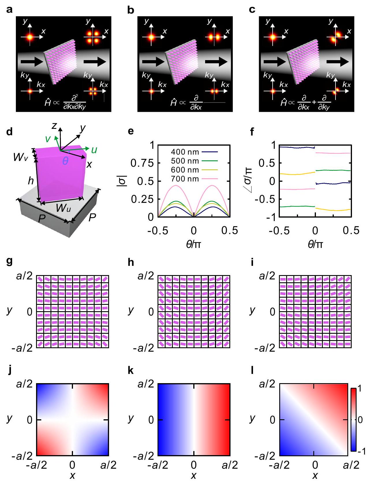
فيما يلي، نعرض السطوح الميتا المصممة لتحقيق هذه العمليات. توضح الأشكال 1a-c بشكل تخطيطي الميتا-
الشكل 1 | مفرق الطيف الزاوي الميتا. أ-ج معالجات ميتا تناظرية للطيف الزاوي لمعالجة التفاضل البصري التناظري في مجال الطيف الزاوي، حيث ينتشر الضوء من خلالها. العملية المقابلة للطيف الزاوي،ودالة نقل معقدة في الفضاء الحقيقي،المقدمة من قبل السطوح الفوقية السيليكونية هي، على التوالي، و و ، و و (ج). يُفترض أنيساوي في (ج). مخطط للعمود النانوي السيليكوني المدور على ركيزة السيليكا مع، ، و السعة (e) والطور (f) لـزاوية الاتجاه مقابلتم قياس معامل الانكسار ومعامل الانقراض للسيليكون بواسطة جهاز الإيليبسومتر (انظر الشكل التكميلي S1 من الملاحظة التكميلية 2)، وتم استخراج معامل الانكسار للسيليكا من المرجع 66. g-1 مخططات العرض العلوي التي تقدم توزيع زوايا الاتجاه. ) وتوزيعات الأجزاء الحقيقية المطلوبة من الثلاثة الميتا-مختلفات (ج-ل) مع و ، على التوالي. المعالجات التي تقوم بأنواع التمايز الثلاثة في مجال الطيف الزاوي. نشير إلى الحافتين المتقابلتين لمقطع السيليكون النانوي على أنهماأيضًا الجوانب الطويلة والقصيرة على طول و الاتجاهات، على التوالي. زاوية التوجيهيمثل الزاوية بينمحور إحداثيات المختبر ومحور (الشكل 1d). معامل النقل المحلي لـالضوء المنقول المستقطب تحتالحادثة المستقطبة (انظر الملاحظة التكميلية 2 للاشتقاق)
أين و هي معاملات النقل المعقدة على طول و الاتجاهات، على التوالي. وبالتالي، لتنفيذ أي من العمليات التي تم مناقشتها أعلاه،يجب أن يتطابق مع دالة النقل في الفضاء الحقيقي المقابلةيمكن تصميم مقاطع العرض الأساسية لبناء كل عمود نانوي للتحكم في و في المعادلة (3)، بغض النظر عن الطول الموجي العامل. بشكل عام، و تعتمد على الطول الموجي، بسبب تشتت المادة وتأثيرات الرنين داخل خلايا وحدات الميتا السطح. بشكل عام، و يمكن أن يتم اختيارها لتكون أيضًا تعتمد على الموقع، من أجل زيادة المرونة في. هنا، للحفاظ على تصميم بسيط، اخترنا استخدام أعمدة نانوية من السيليكون ذات مقطع عرضي ثابت، بحيث و تعتمد فقط على الطول الموجي. من المRemarkably، نوضح أن التعديل فقطيكفي لتحقيقلكل العمليات التفاضلية لطيف الزاوية المعتمدة. نظرًا لأن المطلوبغير صفري في معظم المواقع المكانية، تم اختيار مقطع السيليكون النانوي ليكون مستطيلاً، أي،. لمتباين ميتا يتكون من سطح ميتا مربع بطول جانب ( )، نوضح كيفية تعريف لتحقيق الأنواع الثلاثة المذكورة من التمايز. بالنسبة لنوع الأوليجب أن يرضيمع و يمسك بـيمكن استنتاج أنيجب أن يتم اختياره كـلغرض زيادة كفاءة طيف الزاوية الناتج، المتوافق معباستخدام طريقة مشابهة لتلك المستخدمة في الميتا-تفريق الأول، يمكننا أيضًا استرجاع و للنوعين الآخرين من الميتا-مميزين، المرتبطين بـ و ، على التوالي. يمكن العثور على عملية الاشتقاق التفصيلية في الملاحظة التكميلية 2. يجب ملاحظة أنه، على الرغم من أن الأنواع الثلاثة من المشتقات يمكن أن تعمل عبر نطاق طيفي واسع، إلا أن السعة والانزياح الطوري لطيف الزاوية الناقل تعتمد على الطول الموجي، كما يعتمد على طول موجة الضوء. يجب أيضًا ملاحظة أن الميتا-مميز الفعلي له حجم محدود، وبالتالي يمكنه معالجة نطاق معين فقط من الطيف الزاوي. بالنظر إلى شعاع مدخل بملف غاوسي، فإن نصف قطر الخصرالحد المسموح به له حد أقصى، يعتمد على حجم الميتا-تفاضلي. يمكن العثور على التحليل التفصيلي بشأن دقة الصورة في مجال فورييه في الملاحظة التكميلية 3.
سعة الطيف الزاوي الناقل تتناسب مع فرق السعة بين و . هنا، تم تحسين الهندسة المقطعية لعمود السيليكون النانوي للحصول على فرق كبير في السعة بين و عند 450,532 و 685.5 نانومتر. يتم ترسيب طبقة السيليكون التي تشكل السطح الفوقي بواسطة ترسيب المغناطيسي في التجربة التالية، ويتم قياس معامل الانكسار ومعامل الانقراض بواسطة جهاز الإيليبسومتر. يمكن العثور على تحسين الهندسة العرضية في الشكل التكميلي S1 من الملاحظة التكميلية 2. يتم محاكاة السعة والطور لـ ضد عند أربعة أطوال موجية موضحة في الشكل 1e، f، استنادًا إلى فرق الزمن المحدود مجال (FDTD) مع البرنامج التجاري Lumerical FDTD Solutions. يمكن ملاحظة أن سعةيمكن أن يتغير من صفر إلى قيمة قصوى مثليختلف منإلى، وتعاني المرحلة من تحول كـيتغير من قيمة سلبية إلى قيمة إيجابية. نحن قادرون على تحقيق الأنواع الثلاثة المذكورة من التمايز من خلال ترتيبمن أجل الوفاء بالتوزيعات المطلوبة لـفي سطح ميتا مربع. من خلال ضبطيساوي، ، و ، على التوالي، توزيعات السطح الميت والأجزاء الحقيقية منالمطلوب للتمييزات الثلاثة الميتا موضحة في الشكل 1g-i، والشكل 1j-1، على التوالي.
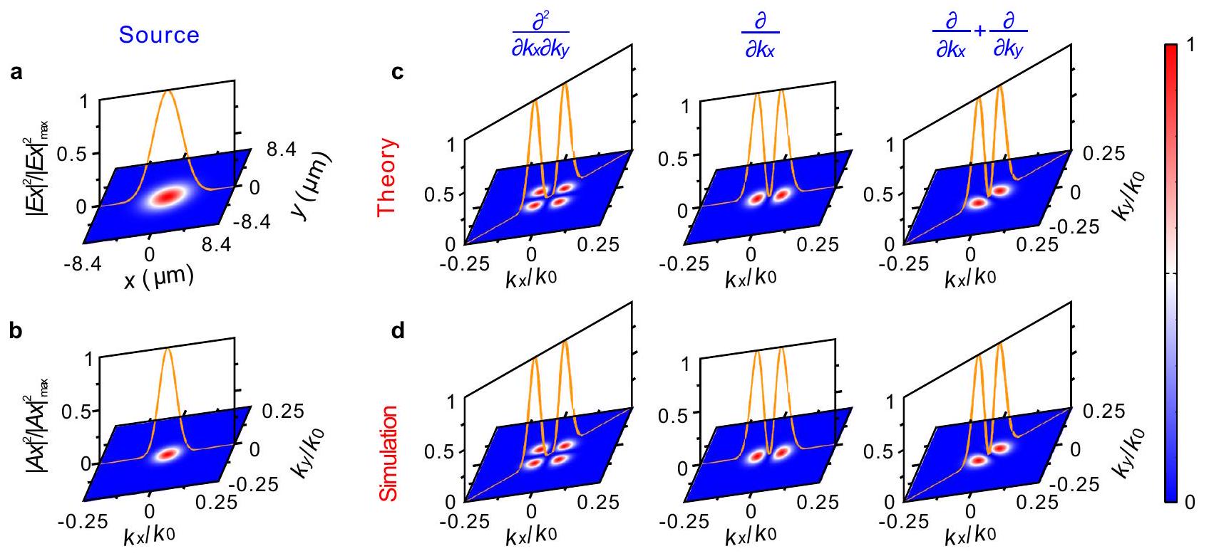
للتحقق من تمايز الطيف الزاوي، نستخدمحزمة غاوسية قطبية كمصدر إدخال لإضاءة الميتا-مشتقات (الشكل 2أ)، حيث يتم عرض الطيف الزاوي المرتبط في الشكل 2ب. الطيف الزاوي المقابل للحزمة المفلترة، المعطى بواسطةيتم حسابه نظريًا لثلاثة أنواع من تمايز الطيف الزاوي (الشكل 2c). ثلاثة ميتا-متميزات معفي الحجم (على سبيل المثال، تستخدم الأعمدة النانوية للتحقق من وظيفة التمايز. يمكننا أولاً الحصول على-توزيعات كثافة المجال للمكونات بعد مرور الشعاع الغاوسي عبر المشتتات الميتا بواسطة محاكاة FDTD، ثم استخراج توزيعات الطيف الزاوي المقابلة لهاعن طريق إجراء تحويل فورييه (الشكل 2d). يجب التأكيد على أن نصف قطر خصر البقعة (أقل من الحد الأعلى لـالنتائج المحاكية متوافقة تمامًا مع النتائج النظرية، مما يشير إلى أن دقة الصورة المحددة في الملاحظة التكميلية 3 تعتبر محافظة إلى حد ما.يؤدي إلى شدة صفرية على طول و المحاور، وأقصى شدة تقع على الخطين و (الشكل 2ج، د). يؤدي إلى شدة صفرية على طول المحور وأقصى شدة تقع على محور فقط.يؤدي إلى صفر من الشدة على طول الخطوتظهر أقصى شدة على الخط. تظهر النتائج النظرية والمحاكاة عند أطوال موجية متقطعة ضمن 450 نانومتر و 1000 نانومتر توزيعات كثافة حقل مشابهة عند 685.5 نانومتر، مما يشير إلى أن المفاضلات الميتا المقترحة تعمل مع عرض نطاق واسع للغاية (انظر الملاحظة التكميلية 4). على الرغم من أن طريقة التصميم يمكن تمديدها إلى مفاضلات ميتا ذات طيف زاوي من ترتيب عشوائي من حيث المبدأ، إلا أنها تطرح
الشكل 2 | توزيعات كثافة الطيف الزاوي لثلاثة أنواع من التمايز. أ، ب كثافة المجال (أ) وشدة الطيف الزاوي (ب) من المدخل-حزمة غاوسية مستقطبة مع نصف قطر الخصر من في توزيع كثافة الطيف الزاوي الناتج لأنواع التمايز الثلاثة: النظرية (ج) والمحاكاة (د). هو عدد الموجات في الهواء. قيود النطاق الترددي لتحقيق مفاضلات أعلى ترتيب بشكل عملي. شدة المجال التي تقدمها المفاضلات الميتا، خاصةً للتفاضيل عالية الترتيب، ليست دائمًا متوافقة مع ما تنبأت به النظرية، على سبيل المثال، فإن المجال الناتج ليس متماثلاً في نطاق الطول الموجي الطويل، وشدة المجال بواسطة المفاضلات الميتا ليست قريبة من الصفر في نطاق الطول الموجي القصير. يمكن العثور على الدراسة التفصيلية حول قيود النطاق الترددي لمفاضلات الطيف الزاوي عالية الترتيب في الملاحظة التكميلية 5.
عرض تجريبي
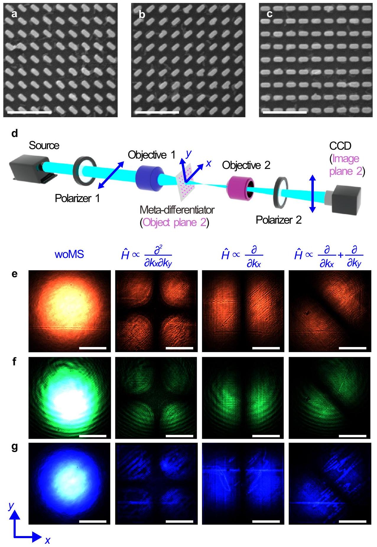
لقد قمنا بتصنيع ثلاثة ميتا-مفاضلات منفي الحجم (أي، الأعمدة النانوية” على -ركيزة سيليكا سميكة للتحقق من الأنواع الثلاثة من تمايز الطيف الزاوي. تُظهر الأشكال 3أ-ج صورًا مأخوذة بواسطة المجهر الإلكتروني الماسح (SEM) في الزاوية السفلى اليمنى من كل ميتا-متميز. تُستخدم إعدادات التجربة (الشكل 3د) للتحقق مما إذا كانالتي تمارسها الميتا-تفاضلات تتماشى مع القيم النظرية المتوقعة بواسطة المعادلة (2). اتجاهات الاستقطاب للمرشحات القطبية متعامدة مع بعضها البعض لاستخراج
الشكل 3 | المجال المقياس للانتقال لأنواع ثلاثة من التفريق. أ-ج صور SEM لعينات جزئية لتفريق الطيف الزاوي مع (أ) (ب) و أشرطة المقياس هي. إعداد تجريبي للقياس. المشتق الميتا وكاميرا CCD موجودان في مستويات الجسم والصورة توزيعات كثافة حقل النقل المسجلة بواسطة CCD مع الضوء الأحمر (685.5 نانومتر) (e)، الضوء الأخضر (532 نانومتر) (f) والضوء الأزرق (450 نانومتر) (g). القضبان المقياسية هي. حقل النقل المتقاطع. يتم ضبط المسافة بين العدسة 1 والمفاضل الميتا لضمان أن شعاع الضوء أصغر قليلاً من المفاضل الميتا عند وصوله إلى الجانب الأيسر منه. تحت إضاءة الضوء الغاوسي الأحمر والأخضر والأزرق، يتم تسجيل حقل النقل المتقاطع بواسطة كاميرا CCD (الشكل 3e-g). تتوافق توزيعات كثافة الحقل الناتجة مع النتائج النظرية، كما هو موضح في الملاحظة التكميلية 6. كثافة الحقل على طول الخطوط أو و ، هو صفر، وهو الحد الأقصى على طول الخطوط أو و ، والتي تتوافق مع الثلاثة ميتا-تفريقات مع، و ، على التوالي.
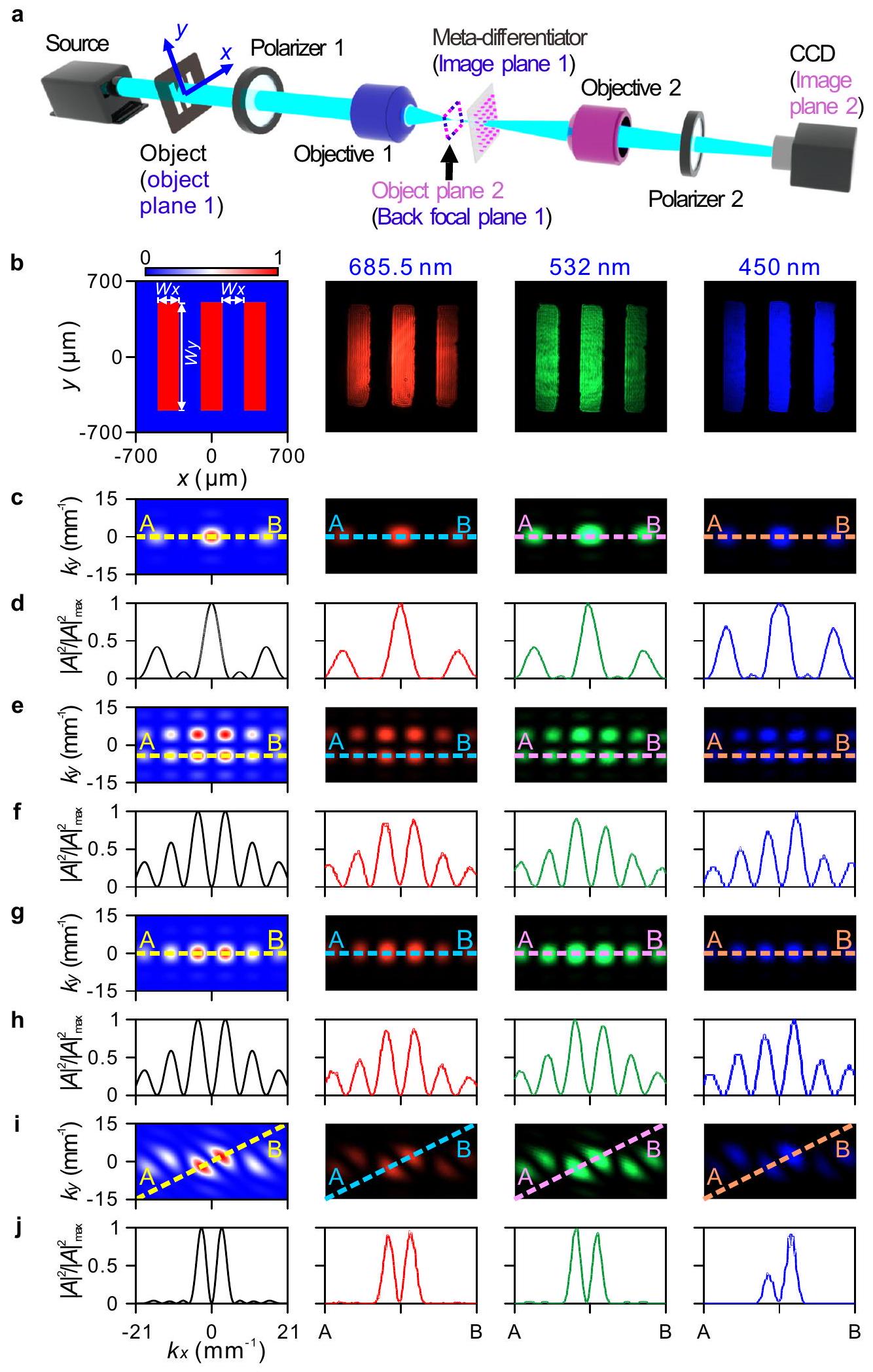
يمكن للتمييز الفوقي تنفيذ عملية التمييز على الطيف الزاوي للأجسام غير التافهة. يتم وضع الجسم الاختباري بين مصدر الضوء والمرشح الأول (الشكل 4أ). يتم أولاً ضبط المسافة بين الجسم والعدسة 1 من أجل تصوير الجسم على التمييز الفوقي. منطقة التصوير أصغر قليلاً من التمييز الفوقي. ثم يتم تحريك العدسة 2 لضمان تصوير مستوى البؤرة الخلفية للعدسة 1 على كاميرا CCD عبر العدسة 2. في هذا السيناريو، الصورة المسجلة بواسطة كاميرا CCD تت correspond إلى تمييز الطيف الزاوي للجسم. يمكن العثور على الشرح التفصيلي حول كيفية استخدام الإعداد التجريبي لاسترجاع تمييز الطيف الزاوي للجسم في الملاحظة التكميلية 7.
في تجربتنا، يتكون الجسم من لوحة فولاذية مقاومة للصدأ مثقوبة بثلاثة ثقوب مستطيلة متوازية وثقب دائري واحد، والذي يتمتع بتباين نقل عالٍ بين المناطق غير الشفافة والشفافة. بالنسبة للثقوب المستطيلة الثلاثة المتوازية، يمكن كتابة المجال الكهربائي المنقول كالتالي
الطيف الزاوي المرتبط والتفريق مع العمليات الثلاث و يمكن العثور عليه في الملاحظة التكميلية 8. يتم رسم المجال الكهربائي المنقول بعد الجسم في اللوحة الأولى من الشكل 4b. الطيف الزاوي الطبيعي المرتبط |مخطط في اللوحة الأولى من الشكل 4c، مع عرض ملف الكثافة في اللوحة الأولى من الشكل 4d. التمايزات الطيفية الزاوية النظرية لـ و موضحة في اللوحة الأولى من الشكل 4e، g، i، على التوالي، حيث تم رسم ملفات الكثافة المرتبطة على طول الخطوط A-B في اللوحة الأولى من الشكل 4f، h، j، على التوالي. الطيف الزاوي عندوتم استخراج 450 نانومتر تجريبيًا وتسجيله بواسطة كاميرا CCD، كما هو موضح في اللوحات من الثانية إلى الرابعة في الشكل 4b-j. التجربة متوافقة تمامًا مع النتائج النظرية المذكورة أعلاه. يمكن ملاحظة أنه، تحت تمايز الطيف الزاوي لـ، يتم تحويل صف واحد يحتوي على ثلاثة نقاط رئيسية (الشكل 4c) إلى صفين، يحتوي كل صف على ست نقاط رئيسية (الشكل 4e، f). بدلاً من ذلك، عندما يتم تنفيذ العملية يعتبر، أن النقاط الثلاث الرئيسية في صف واحد تتحول فقط إلى صف واحد من ست نقاط رئيسية (الشكل. ). يتعرض الطيف الزاوي لتفاضل من الدرجة الأولى على طول الاتجاه مع ، كـ يعادل . نتيجة لذلك، يتم تحويل كل نقطة في صف واحد إلى نقطتين على طول الاتجاه (الشكل 4i، j). من الجدير مناقشة الملف غير المتماثل لتوزيعات كثافة الطيف الزاوي عند 450 نانومتر. يحتوي المستقطب على نسبة انقراض منخفضة لقوى الضوء للاستقطابات العمودية عند الأطوال الموجية الأقصر، على عكس الأطوال الموجية الأطول.يظل شعاع الضوء المستقطب بعد الم polarized 1 ويصل إلى CCD، الذي له شدة مقارنة بشعاع الضوء الذي يساهم في تمييز الطيف الزاوي. نظرًا لأن الجسم هو ثقب دائري واحد، يتم تقديم نتائج عملية تمييز الطيف الزاوي في الملاحظة التكميلية 9.
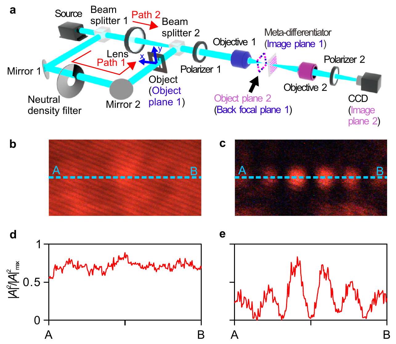
الطيفية المشتقة هي تقنية تُستخدم لعزل الميزات الطيفية الضعيفة عن الميزات القوية غير المرغوب فيها، ويمكن استخدامها أيضًا لتعزيز تباين شريط ضعيف مع إشارة قوية متداخلة في المجال الطيفي. تُستخدم على نطاق واسع في تحليل الشوائب، واختبار النقاء، واختبار الاستقرار.. بينما تعمل التقنيات الحالية في الفضاء الحقيقي، يمكن استخدام المحولات الفوقية لدينا لعزل الميزات في مجال طيف الزاوية لجسم ما. إذا كان طيف الزاوية للجسم، أضعف بكثير من الطيف الزاوي الخلفي الإضافي،لا يمكن التمييز مباشرة و أي أنه لا يمكن اكتشاف طيف الزاوية للشيء لتحليل الأثر. ومع ذلك، يمكن اكتشاف طيف الزاوية للشيء إذا تم تطبيق عملية التفريق على طيف الزاوية للشيء والخلفية، وكانت قيمة التفريق الأولى أكبر بكثير من القيمة الثانية. تم إنشاء الإعداد التجريبي المقابل كما هو موضح في الشكل 5أ، حيث يضيء شعاع من الضوء الشيء (المسار 1)، ثم يتم مزجه مع شعاع آخر من الضوء (المسار 2)، الذي يحاكي خلفية قوية. في هذه الحالة، يرتبط بالطيف الزاوي للثلاث فتحات المستطيلة المتوازية، و يتوافق مع الطيف الزاوي الواسع الناتج عن مصدر يشبه الغاوسي.يمكن أن يكون أصغر بكثير منعن طريق ضبط فلتر الكثافة المحايدة. في هذه الحالة، الطيف الزاوي المختلط بدون الميتا-مشتق حوليظهر في الشكل 5 ب، د. يمكن ملاحظة أن النقاط الثلاث تقريبًا غير مرئية تمامًا (الشكل 5ب، د). على العكس، يمكن ملاحظة النقاط الست التي تحدد تحليل الطيف الزاوي للهدف بوضوح حولبعد أن يتم معالجة الطيف الزاوي المختلط بواسطة الميتا-مشتق (الشكل 5ج، هـ). هذا لأنيتميز بحد أقصى حوالي، والتمييز المرتبط به بالنسبة إلىقريب من الصفر، أصغر من التفاضل لـ.
يجب التأكيد على أن المعالج الميتا-الطيفي الزاوي لدينا قابل أيضًا للتطبيق على التفاضل من الرتبة الأعلى، كما تم توضيحه في الملاحظة التكميلية 5. علاوة على ذلك، بينما ركزنا هنا على العمليات التفاضلية، يمكن توسيع المعالج الميتا لتطوير العديد من الوظائف الأخرى للمعالجة البصرية التناظرية في مجال الطيف الزاوي، مثل التفاضل، والتكامل، والت convolutions، وحل المعادلات. كما أن وحدات تعديل الضوء المكاني قادرة أيضًا على توفير توزيعات متغيرة مكانيًا في السعة والطور، وهي واعدة لتحقيق وظائف عمليات الطيف الزاوي المماثلة. ومع ذلك، فإن المسافة بين وحدات تعديل الضوء المكاني لا تقل عن عدة أطوال موجية، وقد تولد معالجات الطيف الزاوي الناتجة عن وحدات تعديل الضوء المكاني لواحدات جانبية إضافية ناتجة عن الانكسار من الرتبة العالية. بالإضافة إلى عملية التفاضل في الطيف الزاوي، يمكن استكشاف الميتا-تفاضلات لتحقيق عملية التفاضل المكاني، عند دمجها مع نظام 4F. استنادًا إلى هذه الوظيفة، نقدم تعزيز حاد للتباين لرسوم اختبار الدقة وخلايا بيض الضفادع عبر الطيف المرئي بالكامل في الملاحظة التكميلية 10. من خلال استخدام الأعمدة النانوية ذات المقاطع العرضية المتنوعة لتوفير كاملتغطية الطور، من الممكن تحقيق أنواع أخرى من عمليات تمييز الطيف الزاوي، مثل.
يجب التأكيد على أنه، بينما العمليات الرياضية الموضحة هنا تعمل على السعة المعقدة للطيف الزاوي للمجال الكهربائي، فإن كاميرا CCD المستخدمة في تجربتنا يمكنها فقط تسجيل معلومات شدة المجال. وبالتالي، لا يمكن استرجاع معلومات الطور مباشرة في تجربتنا. ومن الجدير أيضًا مناقشة كيف يؤثر خطأ التصنيع على أداء الجهاز. يتمتع الفيلم السيليكوني بملمس سطحي خشونة 10 نانومتر، ويمكن التحكم في عدم اليقين في التصنيع على مقطع السيليكون النانوي ضمن 10 نانومتر. تشير تحليلاتنا ومحاكاة إلى أن خطأ التصنيع يؤثر بالكاد على الدقة المكانية وشدة الصورة الناتجة. أخيرًا، عند تقييم أداء ميتاسطح حسابية سلبية، من الضروري قياس كفاءة المرور، أي كيف تقارن شدة الصورة الناتجة بشدة الصورة المدخلة. يمكن أن تكون هناك مقاييس مختلفة.
الشكل 4 | قياسات تمايز الطيف الزاوي لثلاث فتحات مستطيلة متوازية. أ إعداد تجريبي لتنفيذ عملية الطيف الزاوي لجسم ما. الجسم والمفاضل الميتا موجودان على مستوى الجسم والصورة للعدسة 1، على التوالي. المستوى البؤري الخلفي للعدسة 1 هو أيضًا مستوى الجسم للعدسة 2، وكاميرا CCD موجودة على مستوى الصورة للعدسة 2. ب النظرية (اللوحة الأولى) والتجريبية (من الثانية إلى الرابعة)
توزيعات الكثافة (اللوحات) لثلاث فتحات مستطيلة متوازية مثقوبة في لوحة من الفولاذ المقاوم للصدأ (بسمك 1 مم). تم تعيين المعلمات الهندسية للفتحات عند و توزيعات كثافة الطيف الزاوي (ج) وملفات الكثافة المعنوية على طول الخطوط A-B في (ج) (د). هـ-ي توزيعات كثافة الطيف الزاوي مع، و وملفات شدة الضوء المعيارية الخاصة بهم على طول الخطوط A-B (f، h، j).
الشكل 5 | تجربة عزل الطيف الزاوي. أ إعداد تجريبي لإجراء عزل الطيف الزاوي عند 685.5 نانومتر. ب-هـ توزيعات كثافة الطيف الزاوي للضوء المختلط بدون (ب) ومع (ج) الميتا-مفاضل مع
. ملفات كثافة الطيف الزاوي العادية الخاصة بهم على طول الخطوطمبينان في (د) و (هـ) على التوالي. يستخدم لقياس الكفاءة. “الكفاءة القصوى، يُعرَّف بأنه نسبة شدة القمم في الصور الناتجة والمدخلة، حيثهو شدة الإخراج (الإدخال)يمكن تعريف مقياس آخر من خلال النظر في الكثافات المتكاملة، أيقمنا بحساب كلا المقياسين للقياسات في الشكل 4. بالنسبة لكلا المقياسين، حصلنا على قيم في حدود، اعتمادًا على الطول الموجي والعملية المحددة المعنية. تُعزى الكفاءات المنخفضة نسبيًا بشكل رئيسي إلى تكوين الاستقطاب المتقاطع في إعدادنا، مما يؤدي إلى رفض جزء كبير من الطاقة المدخلة. يمكن زيادة كفاءات النقل من خلال استخدام الميتاسطح العازلة ذات نسبة الأبعاد العالية المصنوعة من مواد منخفضة الفقد، مثل السيليكون البلوري ويمكن العثور على مناقشة مفصلة حول كفاءة النقل في الملاحظة التكميلية 11.
نقاش
في الختام، لقد أظهرنا ‘معالجات ميتا أنغولارية طيفية’ يمكنها تنفيذ تمايز الطيف الزاوي لجسم ما. يمكن تصميم وظيفة النقل البصري بشكل مرن لاستهداف الوظائف المرغوبة لمعالجة الطيف الزاوي. لقد قمنا ببناء ثلاثة أنواع من عمليات الطيف الزاوي استنادًا إلى السطوح الميتا السيليكونية، وأظهرنا قدرتها على تنفيذ تمايز الطيف الزاوي على الأجسام العملية عبر الطيف المرئي بالكامل. كما قدمنا استخدام ميتا-متميز لتحليل الأجسام المستهدفة في مجال الطيف الزاوي. توفر نتائجنا نهجًا جديدًا لمعالجة الصور في مجال الطيف الزاوي، على عكس الاستراتيجيات السابقة في المجال المكاني. مثل هذا التصميم لا يملك فقط آفاق تطبيق واسعة لمعالجة البيانات البصرية التناظرية والتصوير البيولوجي، ولكنه أيضًا يمكّن تقنيات الكشف البصرية الناشئة الجديدة.
طرق
تصنيع
تبدأ عملية تصنيع العينة بإيداع فيلم سيليكون بسمك 220 نانومتر علىتم استخدام ترسيب المغناطيسية لصنع ركيزة السيليكا. تم طلاء طبقة من الفوتوريسست على الفيلم السيليكوني ثم تم خبزها في فرن. بعد ذلك، تم تحديد الأنماط المرغوبة على طبقة الفوتوريسست بواسطة الطباعة الحجرية بالأشعة الإلكترونية (EBL). بعد تطوير الفوتوريسست، يتم نقل النمط إلى طبقة السيليكون بواسطة حفر البلازما المتصلة بالحث (ICP). تم حفر الأهداف التي تحتوي على ثلاثة ثقوب مستطيلة متوازية وثقب دائري واحد في لوحة الفولاذ المقاوم للصدأ بواسطة الحفر.
القياسات
يظهر الإعداد لقياس وظائف نقل السطح الفوقي في الشكل 3d. يتم جمع الضوء من الليزر (الأحمر: DL-690-010-RS، الأخضر: MSL-FN-532-50 mW، الأزرق: DL-450-010-RS) بواسطة العدسة 1 (أوليمبوس UPlanFL N، ) ويتم ضبط المسافة بين العدسة 1 والمفاضلات الميتا لضمان أن يكون شعاع الضوء أصغر قليلاً من المفاضلات الميتا عند وصوله إلى الجانب الأيسر منها. يتم تصوير المجال الضوئي على المفاضلات الميتا بواسطة العدسة 2 (أوليمبوس UPlanFL N، ) وكاميرا CCD (LBAS-U350-35C). اتجاهات الاستقطاب للقطبين متعامدة مع بعضها البعض لاستخراج مجال النقل المتقاطع.
يظهر الإعداد لقياس تمايز الطيف الزاوي في الشكل 4a. يمر الضوء الساقط عبر الجسم ويتم تصوير الجسم على المشتت الميتا بواسطة العدسة 1. يتم ضبط مسافة الجسم ومسافة الصورة لضمان أن الصورة أصغر من المشتت الميتا. ثم يتم تسجيل المجال على مستوى البؤرة الخلفية للعدسة 1 بواسطة العدسة 2 وكاميرا CCD.
اتجاهات الاستقطاب لمرشحين قطبيين متعامدة مع بعضها البعض لاستخراج حقل النقل المتقاطع.
يظهر الإعداد لقياس عزل الطيف الزاوي في الشكل 5a. يتم تقسيم الضوء الساقط إلى شعاعين (المسارات 1 و 2) بواسطة مقسم الشعاع 1. يضيء الضوء على المسار 1 الجسم (أي، الثقوب المستطيلة الثلاثة المتوازية)، ثم يتم تصويره على الميتا-مشتق بواسطة العدسة 1. في نفس الوقت، يتم ضبط حجم البقعة من المسار 2 بواسطة عدسة (Thorlabs LB1471-A) وتكون البقعة أكبر قليلاً منيتم تقليل شدة الشعاع من المسار 1 بواسطة مرشح الكثافة المحايدة لجعل الطيف الزاوي المقابل مغطى تقريبًا بالكامل بالطيف الزاوي الواسع من المسار 2. باستخدام نفس الطريقة لقياس الطيف الزاوي المذكورة في الشكل 4، يمكن استخراج الطيف الزاوي المختلط بدون ومع تمايز الطيف الزاوي لمتباينات الميتا.
توفر البيانات
جميع البيانات المطلوبة لتفسير النتائج في هذه الورقة متاحة ضمن النص الرئيسي والمواد التكميلية. أي بيانات إضافية في هذه الدراسة متاحة من المؤلفين المقابلين عند الطلب.
توفر الشيفرة
الكود الذي يدعم الرسوم البيانية في هذه الورقة متاح من المؤلفين المقابلين عند الطلب.
References
Pan, X., Li, Y., Cheng, B., Liang, S.-J. & Miao, F. 2D materials for intelligent devices. Sci. China Phys. Mech. Astron. 66, 117504-117504 (2023).
Chen, T. The past, present, and future of image and multidimensional signal processing. IEEE Signal Proc. Mag. 15, 21-58 (1998).
Caulfield, H. J. & Dolev, S. Why future supercomputing requires optics. Nat. Photonics 4, 261-263 (2010).
Zangeneh-Nejad, F., Sounas, D. L., Alù, A. & Fleury, R. Analogue computing with metamaterials. Nat. Rev. Mater. 6, 207-225 (2021).
Cordaro, A. et al. High-index dielectric metasurfaces performing mathematical operations. Nano Lett. 19, 8418-8423 (2019).
Wu, J. et al. Analog optical computing for artificial intelligence. Engineering 10, 133-145 (2022).
Li, C., Zhang, X., Li, J., Fang, T. & Dong, X. The challenges of modern computing and new opportunities for optics. PhotoniX 2, 20 (2021).
Wang, Z. et al. Single-layer spatial analog meta-processor for imaging processing. Nat. Commun. 13, 2188 (2022).
Fu, W. et al. Ultracompact meta-imagers for arbitrary all-optical convolution. Light.: Sci. Appl. 11, 62 (2022).
Oti, J. E., Canales, V. F. & Cagigal, M. P. The optical differentiation coronagraph. Astrophys. J. 630, 631-636 (2005).
Oti, J. E., Canales, V. F. & Cagigal, M. P. Analysis of the signal-tonoise ratio in the optical differentiation wavefront sensor. Opt. Express 11, 2783-2790 (2003).
Park, Y., Azaña, J. & Slavík, R. Ultrafast all-optical first- and higherorder differentiators based on interferometers. Opt. Lett. 32, 710-712 (2007).
Ngo, N. Q., Yu, S. F., Tjin, S. C. & Kam, C. H. A new theoretical basis of higher-derivative optical differentiators. Opt. Commun. 230, 115-129 (2004).
Zhang, W., Wang, Y., Xu, D., Luo, H. & Wen, S. All-optical differentiator in frequency domain. Appl. Phys. Lett. 120, 011102 (2022).
Chen, J., Wang, B., Zhu, L., Han, J. & Xu, Q. Metalens for coaxial double wavelength focusing. Chin. Opt. Lett. 18, 042401 (2020).
He, Y., Song, B. & Tang, J. Optical metalenses: fundamentals, dispersion manipulation, and applications. Front. Optoelectron. 15, 24 (2022).
Hu, T., Feng, X., Yang, Z. & Zhao, M. Design of scalable metalens array for optical addressing. Front. Optoelectron. 15, 32 (2022).
Arbabi, A. & Faraon, A. Advances in optical metalenses. Nat. Photonics 17, 16-25 (2023).
Deng, Z.-L. et al. Diatomic metasurface for vectorial holography. Nano Lett. 18, 2885-2892 (2018).
Deng, Z.-L. et al. Facile metagrating holograms with broadband and extreme angle tolerance. Light.: Sci. Appl. 7, 78 (2018).
Wang, H. et al. Tailoring circular dichroism via the born-kuhn model formeta-holograms. Sci. China.: Phys. Mech. Astron. 65, 104212 (2022).
So, S. et al. Multicolor and 3D holography generated by inversedesigned single-cell metasurfaces. Adv. Mater. 35, 2208520 (2023).
Balthasar Mueller, J. P., Leosson, K. & Capasso, F. Ultracompact metasurface in-line polarimeter. Optica 3, 42 (2016).
Huang, Z. et al. High-resolution metalens imaging polarimetry. Nano Lett. 23, 10991-10997 (2023).
Kurosawa, H., Choi, B., Sugimoto, Y. & Iwanaga, M. Highperformance metasurface polarizers with extinction ratios exceeding 12000. Opt. Express 25, 4446 (2017).
Arbabi, A., Arbabi, E., Horie, Y., Kamali, S. M. & Faraon, A. Planar metasurface retroreflector. Nat. Photonics 11, 415-420 (2017).
Yan, L. et al. thick adaptive retroreflector made of spin-locked metasurface. Adv. Mater. 30, 1802721 (2018).
Li, M. et al. Angular-adaptive spin-locked retroreflector based on reconfigurable magnetic metagrating. Adv. Opt. Mater. 7, 1900151 (2019).
Kamali, S. M. et al. Angle-multiplexed metasurfaces: encoding independent wavefronts in a single metasurface under different illumination angles. Phys. Rev. X 7, 041056 (2017).
Wan, S. et al. Angular-multiplexing metasurface: building up independent-encoded amplitude/phase dictionary for angular illumination. Adv. Opt. Mater. 9, 2101547 (2021).
Khorasaninejad, M. et al. Metalenses at visible wavelengths: diffraction-limited focusing and subwavelength resolution imaging. Science 352, 1190-1194 (2016).
Khorasaninejad, M. et al. Multispectral chiral imaging with a metalens. Nano Lett. 16, 4595-4600 (2016).
Wang, S. et al. A broadband achromatic metalens in the visible. Nat. Nanotechnol. 13, 227-232 (2018).
Chen, W. T. et al. Broadband achromatic metasurface-refractive optics. Nano Lett. 18, 7801-7808 (2018).
Abdollahramezani, S., Chizari, A., Dorche, A. E., Jamali, M. V. & Salehi, J. A. Dielectric metasurfaces solve differential and integrodifferential equations. Opt. Lett. 42, 1197-1200 (2017).
Silva, A. et al. Performing mathematical operations with metamaterials. Science 343, 160-163 (2014).
Zhou, J. et al. Optical edge detection based on high-efficiency dielectric metasurface. Proc. Natl Acad. Sci. USA 116, 11137-11140 (2019).
Zhou, Y. et al. Analog optical spatial differentiators based on dielectric metasurfaces. Adv. Opt. Mater. 8, 1901523 (2019).
Abdolali, A., Momeni, A., Rajabalipanah, H. & Achouri, K. Parallel integro-differential equation solving via multi-channel reciprocal bianisotropic metasurface augmented by normal susceptibilities. N. J. Phys. 21, 113048 (2019).
Chen, H., An, D. & Zhao, X. Quasi-periodic dendritic metasurface for integral operation in visible light. Molecules 25, 1664 (2020).
Liao, K., Gan, T., Hu, X. & Gong, Q. Al-assisted on-chip nanophotonic convolver based on silicon metasurface. Nanophotonics 9, 3315-3322 (2020).
Pan, D. et al. Laplace metasurfaces for optical analog computing based on quasi-bound states in the continuum. Photon. Res. 9, 1758-1766 (2021).
Zhou, J. et al. Two-dimensional optical spatial differentiation and high-contrast imaging. Natl Sci. Rev. 8, nwaa176 (2021).
Cotrufo, M., Singh, S., Arora, A., Majewski, A. & Alù, A. Polarization imaging and edge detection with image-processing metasurfaces. Optica 10, 1331-1338 (2023).
Cotrufo, M., Arora, A., Singh, S. & Alù, A. Dispersion engineered metasurfaces for broadband, high-NA, high-efficiency, dualpolarization analog image processing. Nat. Commun. 14, 7078 (2023).
Bao, L., Wu, R. Y., Fu, X. & Cui, T. J. Mathematical operations of transmissive near fields controlled by metasurface with phase and amplitude modulations. Ann. Phys. 532, 2000069 (2020).
Guo, C., Xiao, M., Minkov, M., Shi, Y. & Fan, S. Photonic crystal slab laplace operator for image differentiation. Optica 5, 251-256 (2018).
Zhou, Y., Zheng, H. Y., Kravchenko, I. I. & Valentine, J. Flat optics for image differentiation. Nat. Photonics 14, 316-323 (2020).
Zhu, T. et al. Generalized spatial differentiation from the spin hall effect of light and its application in image processing of edge detection. Phys. Rev. Appl. 11, 034043 (2019).
He, S. et al. Wavelength-independent optical fully differential operation based on the spin-orbit interaction of light. APL Photonics 5, 036105 (2020).
Zhu, T. et al. Plasmonic computing of spatial differentiation. Nat. Commun. 8, 15391 (2017).
Liu, W., Zhang, W. & Yao, J. Silicon-based integrated tunable fractional order photonic temporal differentiators. J. Light. Technol. 35, 2487-2493 (2017).
Ming, X. et al. Simple reconfigurable multiport photonic temporal differentiator and integrator based on dual-ring coupled mach-zehnder interferometer. J. Nanophotonics 16, 016004 (2022).
Xu, X. et al. 11 TOPS photonic convolutional accelerator for optical neural networks. Nature 589, 44-51 (2021).
Feldmann, J. et al. Parallel convolutional processing using an integrated photonic tensor core. Nature 589, 52-58 (2021).
lizuka, K. Elements of Photonics 1st edn, Vol I 61-64 (Wiley, New York, 2002).
Braslavsky, I. et al. Objective-type dark-field illumination for scattering from microbeads. Appl. Opt. 40, 5650-5657 (2001).
Ueno, H. et al. Simple dark-field microscopy with nanometer spatial precision and microsecond temporal resolution. Biophys. J. 98, 2014-2023 (2010).
Settles, G. S. & Hargather, M. J. A review of recent developments in schlieren and shadowgraph techniques. Meas. Sci. Technol. 28, 042001 (2017).
Wang, W., Dong, R. & Yang, W. Sensitivity investigation of schlieren imaging system. Laser Optoelectron. Prog. 55, 111102 (2018).
Zernike, F. How i discovered phase contrast. Science 121, 345-349 (1955).
Guo, W.-L. et al. Airy beam generation: approaching ideal efficiency and ultra wideband with reflective and transmissive metasurfaces. Adv. Opt. Mater. 8, 2000860 (2020).
Song, S.-B., Choi, J.-K. & Yoo, G.-S. Determination of total glycyrrhetic acid in glycyrrhizae radix by second derivative UV spectrometry. Arch. Pharm. Res. 13, 174-179 (1990).
Kitamura, K., Takagi, M. & Hozumi, K. Determination of aspirin and salicylic acid in aspirin tablets by second derivative ultraviolet spectrometry. Chem. Pharm. Bull. 32, 1484-1490 (1984).
Palik, E. D. Handbook of Optical Constants of Solids, Vol I 749-764 (Academic Press, 1985).
شكر وتقدير
تدعم L.C. من قبل المشروع الوطني الرئيسي للبحث والتطوير في الصين (رقم المنحة 2021YFB2801903)، ومؤسسة العلوم الطبيعية الوطنية في الصين (رقم المنحة 12074137)، ولجنة العلوم والتكنولوجيا والابتكار لبلدية شنتشن (رقم المنحة. JCYJ20220530161010023). تم دعم M.C. و A.A. من قبل مكتب الأبحاث العلمية للقوات الجوية ومؤسسة سيمونز. نشكر الدكتور جون سو في منشأة تصنيع وتوصيف الميكرو والإلكترونيات الضوئية، WNLO، HUST على قياس SEM.
مساهمات المؤلفين
قام م.د.، ل.س. بتصور الفكرة وبدء العمل. قاد ل.س.، أ.أ. المشروع. طور م.د. الإطار النظري، وأجرى المحاكاة العددية، وأجرى التجارب. ناقش ج.و.، ج.د.، ز.ر. النتائج. كتب م.د.، ل.س.، م.ج.، أ.أ. المخطوطة وراجع جميع المؤلفين المخطوطة.
المختبر الوطني في ووهان للإلكترونيات الضوئية وكلية المعلومات البصرية والإلكترونية، جامعة هواتشونغ للعلوم والتكنولوجيا، ووهان 430074، الصين.مبادرة الفوتونيات، مركز أبحاث العلوم المتقدمة، جامعة مدينة نيويورك، نيويورك، NY 10031، الولايات المتحدة الأمريكية.معهد البصريات، جامعة روتشستر، روتشستر، نيويورك 14627، الولايات المتحدة الأمريكية.مدرسة الفيزياء، مختبر تشجيانغ الإقليمي الرئيسي لتكنولوجيا الكم والأجهزة، والمختبر الرئيسي للدولة للبصريات المتطرفة والأجهزة، جامعة تشجيانغ، هانغتشو 310027، الصين.معهد أبحاث جامعة هوا تشونغ للعلوم والتكنولوجيا في شنتشن، شنتشن 518063، الصين.ساهم هؤلاء المؤلفون بالتساوي: مينغ دينغ، ميشيل كوتروفو.البريد الإلكتروني: aalu@gc.cuny.edu; chen.lin@mail.hust.edu.cn
Signal processing is of critical importance for various science and technology fields. Analog optical processing can provide an effective solution to perform large-scale and real-time data processing, superior to its digital counterparts, which have the disadvantages of low operation speed and large energy consumption. As an important branch of modern optics, Fourier optics exhibits great potential for analog optical image processing, for instance for edge detection. While these operations have been commonly explored to manipulate the spatial content of an image, mathematical operations that act directly over the angular spectrum of an image have not been pursued. Here, we demonstrate manipulation of the angular spectrum of an image, and in particular its differentiation, using dielectric metasurfaces operating across the whole visible spectrum. We experimentally show that this technique can be used to enhance desired portions of the angular spectrum of an image. Our approach can be extended to develop more general angular spectrum analog meta-processors, and may open opportunities for optical analog data processing and biological imaging.
Signal processing is vital for several science and engineering disciplines. The increasing demand for high-speed and high-efficiency signal processing has inspired scientists to develop faster, integrated and efficient devices that can process signals and images . Digital signal processing based on integrated electric circuits can perform complex data processing, but it needs an analog-to-digital converter to discretize the input analog signal into a series of bits. After being processed according to the desired operation, the discrete signals are converted back into analog signals through a digital-to-analog converter. This method suffers from low-speed, large memory requirements and high-power consumption, originating from complicated conversion process and hardware bottleneck .
Optical analog processing, with the ability to perform massive parallel processing with high-speed and low-power consumption, has gained significant attention . Optical analog processing has been demonstrated both in the spatial and temporal domain with, e.g., conventional 4 F systems, interferometers and Soleil Babinet compensators. The first-order temporal differentiator was realized by introducing different time delays for two mutually orthogonally polarized components through a Soleil Babinet compensator . However, the resultant optical systems are bulky, and hence are against high-density optical integration. Conventional optical elements do not offer the opportunity to spatially and continuously vary transmission amplitude and phase at the sub-wavelength scale. Metasurfaces, planar arrays composed of subwavelength artificial meta-atoms, provide
opportunities to manipulate light by locally tailoring the amplitude, phase and polarization with much more flexibility. A number of compact optical devices have been developed using metasurfaces, such as lenses , holography systems , polarimeters , polarization elements , retroreflectors and optical imaging encoding . Recently, the research interest has shifted towards practical applications of metasurfaces, such as high-quality imaging and optical analog computation . A wide range of optical analog computations using metasurfaces, such as spatial imaging differentiation , integration , convolution and equation solving , have been successfully demonstrated. Spatial differentiation has also been realized using photonic crystals , spin Hall effect , and surface plasmonbased devices . Realizing spatial differentiation requires a transfer function featuring a zero at normal incidence, in order to suppress the average of the input image and enhance its edges. Generally, most strategies rely on resonant mechanisms to generate this transmission dip. As a result, they often work only in a narrow band of frequencies. Recent works have proposed ways to overcome this challenge based on dispersion engineering . Bragg gratings and microring resonators can also provide a compact method to enable temporal differentiation . The working bandwidth of microring resonators however is intrinsically low, smaller than those based on Bragg gratings and interferometers . The limited operation bandwidth may restrict the capability of exploiting wavelength division multiplexing to enhance data processing speed, which is important for large-scale and high-speed optical analog computation . Spatial and temporal differentiation have been exploited for applications in edge detection, optical processing of microwave signals, analog-digital conversion, pulse shaping, and darksoliton detection .
Fourier optics provides a powerful approach to optical processing, by filtering the frequency components of the angular spectrum of the input image. In a conventional 4 F system, the image to be processed is decomposed into its spatial Fourier components by a first optical lens. Various components to filter the spatial frequencies, made by bulky diffractive optical elements, including pinholes, opaque dots, masks and phase plate shifters , can then be exploited for angular spectrum filtering of the incoming waves, leading to imaging applications, such as dark-field , schlieren , and phase-contrast imaging . However, imparting mathematical operations on the angular spectrum has not been explored to the best of our knowledge. In this paper, we demonstrate metasurfaces that perform mathematical operations on the angular spectrum of an image – “angular spectrum analog meta-processors”-that can be used to perform optical analog processing of the Fourier spectrum-such as differentiation, integration, convolution, and other linear operations as light propagates through them. Depending on the optical operations of interest for angular spectrum processing, we retrieve the required amplitude and phase modulation on the incoming light. We demonstrate differentiation of the angular spectrum based on dielectric metasurfaces across the whole visible frequencies, and we apply it to demonstrate novel applications in the angular spectrum domain, i.e., enhancement of desired angular spectrum features. It should be noted that the angular spectrum differentiation could be also realized by using a lens to extract the angular spectrum, followed by a spatial differentiator to complete angular spectrum differentiation. However, this approach would result in a bulky device. In contrast, here we propose a compact approach to realize angular spectrum differentiation by using a single metasurface. The application potential of enhancing desired portions of the angular spectrum of an image has not been previously exploited in the field of optical analog processing.
Results
Design principles and simulation results
The angular spectrum of an incoming wavefront can be retrieved by performing the Fourier transform of the in-plane electric
field distribution
where is is the imaginary unit, indicates the Fourier transform, labels the -( -) component, and are 2D Fourier domain variables along and directions, respectively. and represent the complex amplitudes of the electric field in the Fourier and spatial domain, respectively. After passing through an optical diffractive element, the angular spectrum is transformed to , where is the angular spectrum operation exerted by the optical diffractive element, modulating the amplitude and phase of of the incoming wavefront. If an arbitrary order differentiation is exerted on the Fourier transform , we have
where indicates the differentiation type, and denotes the maximum number of differentiation type ( is a positive integer, and ). and are natural numbers labeling the order of the partial derivative with respect to and , respectively, and is a complex coefficient (associated with the -th differentiation type), affecting the efficiency and phase delay for the output angular spectrum. Such differential operation in the Fourier domain can be realized by a real-space transfer function , which is related to via Eq. (2). In other words, we assume that the input image, described by the spatial domain electric field , is filtered by a spatially varying mask with transmission amplitude and phase. We first discuss the general properties of the required mask, and then we show how this real-space transfer function can be achieved with a metasurface. For example, if , there is only one term in Eq. (2), associated with and . If is chosen as , then is equal to , associated with . The input angular spectrum will contain second-order partial derivatives with respect to and , respectively. If with , the input angular spectrum will merely consist of the first-order partial derivative with respect to . If , there are two types of differentiation, associated with ( ) = ( ) and ( ), and , . By choosing and , with , a sum over the two firstorder partial derivatives with respect to and , will be applied on the input angular spectrum. The values of and used for the three types of differentiation can be found in Supplementary Table S1 of Supplementary Note 1. The real-space transfer function provided by the optical diffractive elements should be proportional to and , respectively, to realize these three types of differentiation. It should be emphasized that, in principle, we can also realize linear combinations of higher-order partial derivatives by flexibly choosing , and ( ). For example, we can achieve with , associated with , and , and with , associated with , and .
In the following, we demonstrate metasurfaces tailored to realize these operations. Figure 1a-c schematically show the analog meta-
Fig. 1 | Angular spectrum meta-differentiator. a-c Angular spectrum analog meta-processors for optical analog differentiation processing in the angular spectrum domain, as light propagates through them. The corresponding angular spectrum operation, , and complex real-space transfer function, , provided by the silicon metasurfaces are, respectively, and and , and and (c). It is assumed that is equal to in (c). Schematic of the rotated silicon nanopillar on a silica substrate with , , and Amplitude (e) and phase (f) of versus orientation angle . The refractive index and extinction coefficient of silicon were measured by an ellipsometer (see Supplementary Fig. S1 of Supplementary Note 2), and the refractive index of silica is extracted from Ref. 66. g-1 Schematics of the top view presenting the distribution of the orientation angles ( ) and distributions of the real parts of the required of the three metadifferentiators (j-l) with and , respectively.
processors that perform the three types of differentiation in the angular spectrum domain. We denote the two opposing edges of the silicon nanopillar cross-section as , namely the long and short sides along and directions, respectively. The orientation angle represents the angle between the axis of laboratory coordinate and axis (Fig. 1d). The local transmission coefficient for polarized transmitted light under -polarized incidence is (see Supplementary Note 2 for the derivation)
where and are the complex transmission coefficients along and directions, respectively. Thus, to implement any of the operations discussed above, needs to match the corresponding real-space transfer function . The cross sections of the basic building blocks of each nanopillar can be tailored to control and in Eq. (3), regardless of the operating wavelength. In general, and are wavelength-dependent, due to the material dispersion and resonant effects within the metasurface unit cells. In general, and could be chosen to be also position-dependent, in order to increase the flexibility of . Here, to keep the design simple, we have chosen to employ silicon nanopillars with a fixed cross section, so that and
are wavelength-dependent only. Remarkably, we show that modulating only is sufficient to achieve for all angular spectrum differential operations considered. Since the required is nonzero at almost every spatial position, the cross section of the silicon nanopillar is chosen to be rectangular, i.e., . For a metadifferentiator composed of a square metasurface with a side length ( ), we show how to define to achieve the aforementioned three types of differentiation. For the first type should satisfy with and holds with . It can be inferred that should be chosen as for the purpose of maximizing the efficiency of the output angular spectrum, corresponding to . Using a similar method as for the first meta-differentiator, we can also retrieve and for the other two types of meta-differentiators, associated with and , respectively. The detailed derivation process can be found in Supplementary Note 2. It should be noted that, although the three types of differentiator can work over a wide spectral band, the amplitude and phase shift of the transmissive angular spectrum are wavelength-dependent, as is dependent on the light wavelength. It should also be noted that the actual meta-differentiator has a limited size, and thus it can only process a certain range of angular spectrum. Considering an input beam with a Gaussian profile, the waist radius allowed has an upper limit, which depends on the size of the metadifferentiator. The detailed analysis regarding the image resolution in the Fourier domain can be found in Supplementary Note 3.
The amplitude of the transmissive angular spectrum is proportional to the amplitude difference between and . Here, the cross-sectional geometry of the silicon nanopillar is optimized to obtain a large amplitude difference between and at 450,532 and 685.5 nm . The silicon layer forming the metasurfaces is deposited by magnetron sputtering in the following experiment, and its refractive index and extinction coefficient is measured by an ellipsometer. The optimization of crosssectional geometry can be found in Supplementary Fig. S1 of Supplementary Note 2. The simulated amplitude and phase of versus at four wavelengths are shown in Fig. 1e, f, based on finite difference time
domain (FDTD) with the commercial software Lumerical FDTD Solutions. It can be seen that the amplitude of can be changed from zero to a maximum value as is varied from to , and the phase suffers from a shift as changes from a negative value to a positive value. We are able to achieve the aforementioned three types of differentiation by arranging so as to fulfill the required distributions of in a square metasurface. By setting equal to , , and , respectively, the metasurface distributions and the real parts of required for the three meta-differentiators are shown in Fig. 1g-i, and Fig. 1j-1, respectively.
To verify the angular spectrum differentiation, we use an polarized Gaussian beam as the input source to illuminate the metadifferentiators (Fig. 2a), where the associated angular spectrum is shown in Fig. 2b. The corresponding angular spectrum of the filtered beam, given by , is theoretically calculated for three types of angular spectrum differentiation (Fig. 2c). Three metadifferentiators with in size (e.g., nanopillars) are used to validate the differentiation functionality. We can first obtain the -component field intensity distributions after the Gaussian beam passes through the meta-differentiators by FDTD simulations, and then extract their corresponding angular spectrum distributions by performing the Fourier transform (Fig. 2d). It should be emphasized that the spot waist radius ( ) is lower than the upper limit of . The simulated results are perfectly consistent with the theoretical results, which suggests the image resolution defined in Supplementary Note 3 is rather conservative. results in zero intensity along and axes, and the maximum intensity is located on the two lines and (Fig. 2c, d). results in zero intensity along axis and the maximum intensity is located on axis only. leads to zero intensity along the line and the maximum intensity appears on the line . The theoretical and simulated results at discrete wavelengths within 450 nm and 1000 nm show similar field intensity distributions at 685.5 nm , suggesting the proposed meta-differentiators works with an extremely broad bandwidth (see Supplementary Note 4). Although the design method can be extended to arbitrary order angular spectrum meta-differentiators in principle, it poses
Fig. 2 | Angular spectrum intensity distributions for three types of differentiations. a, b Field intensity (a) and angular spectrum intensity (b) of the input -polarized Gaussian beam with a waist radius of at Output angular spectrum intensity distributions for the three types of differentiations: theory (c) and simulation (d). is the wavenumber in the air.
bandwidth limitations for practically realizing higher order metadifferentiators. The field intensity offered by the meta-differentiators, especially for high order differentiation, is not always consistent with that predicted by theory, e. g., the output field is not symmetric in the long wavelength range, and the field intensity by the meta-differentiators is not so close to zero in the short wavelength range. The detailed study on bandwidth limitation for higher order angular spectrum meta-differentiators can be found in Supplementary Note 5.
Experimental demonstration
We have fabricated three meta-differentiators of in size (i.e., nanopillars) on a -thick silica substrate to verify the three types of angular spectrum differentiation. Figure 3a-c show scanning electron microscope (SEM) images taken at the lower right corner of each meta-differentiator. The experimental setup (Fig. 3d) is used to check if exerted by the meta-differentiators is consistent with the theoretical values predicted by Eq. (2). The polarization directions of two polarizers are mutually orthogonal to extract
Fig. 3 | Measured transmission field for three types of differentiations. a-c SEM images of partial samples for angular spectrum differentiation with (a) (b) and . The scale bars are . d Experimental setup for measurement. The meta-differentiator and the CCD camera are on the object and the image planes
of objective 2, respectively. e-g Transmission field intensity distributions recorded by CCD with red light ( 685.5 nm ) (e), green light ( 532 nm ) (f) and blue light ( 450 nm ) (g). The scale bars are .
the cross-polarized transmission field. The distance between objective 1 and the meta-differentiator is adjusted to ensure that the light beam is slightly smaller than the meta-differentiator when reaching the left side of it. Under the illumination of red, green, and blue Gaussian light, the cross-polarized transmission field is recorded by the CCD camera (Fig. 3e-g). The output field intensity distributions are consistent with the theoretical results, as shown in Supplementary Note 6. The field intensity along lines or and , is zero, and is maximum along lines or and , corresponding to the three metadifferentiators with , and , respectively.
The meta-differentiator can implement differentiation operation on the angular spectrum of nontrivial objects. The test object is placed between the light source and the first polarizer (Fig. 4a). The distance between the object and objective 1 is first adjusted in order to image the object onto the meta-differentiator. The imaging area is slightly smaller than the meta-differentiator. Then objective 2 is moved to ensure the back focal plane of objective 1 is imaged onto the CCD camera via objective 2 . In this scenario, the image recorded by the CCD camera corresponds to the differentiation of the object angular spectrum. The detailed explanation on how to use the experimental setup to retrieve the differentiation of the object angular spectrum can be found in Supplementary Note 7.
In our experiment, the object consists of a stainless steel plate drilled by three parallel rectangular holes and a single circular hole, which has a high transmission contrast between opaque and transparent regions. For the three parallel rectangular holes, the transmitted electric field can be written as
The associated angular spectrum and differentiation with the three operations and can be found in Supplementary Note 8. The transmitted electric field after the object is plotted in the first panel of Fig. 4b. The associated normalized angular spectrum | is plotted in the first panel of Fig. 4c, with the intensity profile being shown in the first panel of Fig. 4d. The theoretical angular spectrum differentiations for and are shown in the first panel of Fig. 4e, g, i, respectively, where the associated intensity profiles along lines A-B are plotted in the first panel of Fig. 4f, h, j, respectively. The angular spectrum at and 450 nm are experimentally extracted and recorded by the CCD camera, as shown in the second to the fourth panels in Fig. 4b-j. The experiment is well consistent with the above theoretical results. It can be seen that, under the angular spectrum differentiation of , a single row containing three main spots (Fig. 4c) is transformed into two rows, in which each row contains six main spots (Fig. 4e, f). Instead, when the operation is considered, the three main spots in one row are only transformed into one row of six main spots (Fig. ). The angular spectrum experiences a first-order differentiation along direction with , as is equivalent to . As a result, under this operation each spot in one row is transformed into two spots along direction (Fig. 4i, j). It is worth discussing the antisymmetric profile for the angular spectrum intensity distributions at 450 nm . The polarizer has low extinction ratio of optical powers of perpendicular polarizations at shorter wavelengths, as opposed to longer wavelengths. The -polarized light beam after polarizer 1 remains and reaches the CCD, which has an intensity comparable to the light beam contributing to angular spectrum differentiation. As the object is a single circular hole, the angular spectrum differentiation operation results are presented in Supplementary Note 9.
Derivative spectroscopy is a technique used to isolate weak spectral features from other unwanted strong features, and it can also be used to strengthen the contrast of a weak band to a strong overlapped signal in the spectral domain. It is widely used for trace analysis, purity test, and stability test . While existing techniques operate in real space, our meta-differentiators can be used for isolating features in the angular spectrum domain of an object. If the object angular spectrum, , is much weaker than the additional background angular spectrum, , it is not possible to directly distinguish and , i.e., one cannot detect the object angular spectrum for trace analysis. However, the object angular spectrum can be detected if the differentiation operation is applied on the object and background angular spectra, and the former differentiation value is much larger than the latter one. The corresponding experimental setup is established as shown in Fig. 5a, where one beam of light illuminates the object (path 1), and then is mixed with another beam of light (path 2), which mimics a strong background. In this case, is associated with the angular spectrum of the three parallel rectangular holes, and corresponds to the wide angular spectrum generated by a Gaussian-like source. can be made much smaller than by tuning a neutral density filter. In this situation, the mixed angular spectrum without the meta-differentiator around is shown in Fig. 5 b , d. It can be seen that the three spots are almost completely invisible (Fig. 5b, d). On the contrary, the six spots that define the angular spectrum decomposition of the target can be instead clearly observed around after the mixed angular spectrum is processed by the meta-differentiator with (Fig. 5c, e). This is because features a maximum around , and the associated differentiation with respect to is close to zero, smaller than the differentiation of .
It should be emphasized that our angular spectrum analog metaprocessor is also applicable to higher order differentiation, as has been shown in Supplementary Note 5. Moreover, while here we have focused on differential operations, the meta-processor may be extended to develop many other optical analog processing functionalities in the angular spectrum domain, such as differentiation, integration, convolution and equation solving. Spatial light modulators are also capable of providing spatially varying amplitude and phase distributions, and they are promising for achieving analogous angular spectrum operation functionalities. However, a pixel pitch of spatial light modulators is at least several wavelengths in size, and the resultant angular spectrum processors based on spatial light modulators may generate additional side lobes arising from high order diffraction. In addition to angular spectrum differentiation operation, the metadifferentiators may be explored to realize spatial differentiation operation, when combined with a 4 F system. Based on this functionality, we present high-contrast edge enhancement of resolution test charts and frog egg cells across the whole visible spectrum in Supplementary Note 10. By using nanopillars of varied cross-sections to provide full phase coverage, it is possible to realize other types of angular spectrum differentiation operation, such as .
It should be emphasized that, while the mathematical operations demonstrated here operate on the complex amplitude of the angular spectrum of the electric field, the CCD camera used for our experiment can only record the field intensity information. Consequently, the phase information cannot be directly retrieved in our experiment. It is also worth discussing how the fabrication error affects the device performance. The silicon film has a surface roughness of 10 nm , and the fabrication uncertainty on the cross section of the silicon nanopillar can be controlled within 10 nm . Our analysis and simulation indicate that the fabrication error hardly influences the spatial resolution and the intensity of the output image. Finally, when assessing the performance of a passive computational metasurface, it is crucial to quantify the throughput efficiency, that is, how the intensity of the output image compares to the intensity of the input image. Different metrics can be
Fig. 4 | Measured angular spectrum differentiations of three parallel rectangular holes. a Experimental setup for performing angular spectrum operation of an object. The object and the meta-differentiator are on the object and the image planes of objective 1, respectively. The back focal plane of objective 1 is also the object plane of objective 2 and the CCD camera is on the image plane of the objective 2. b Theoretical (the first panel) and experimental (the second to fourth
panels) intensity distributions of three parallel rectangular holes drilled in a stainless steel plate ( 1 mm thick). The geometrical parameters of the holes are set at and Angular spectrum intensity distributions (c) and normalized intensity profiles along lines A-B in (c) (d). e-j Angular spectrum intensity distributions with , and , and their normalized intensity profiles along lines A-B (f, h, j).
Fig. 5 | Angular spectrum isolation experiment. a Experimental setup for performing angular spectrum isolation at 685.5 nm . b-e Angular spectrum intensity distributions of the mixed light without (b) and with (c) the meta-differentiator with
. Their normalized angular spectrum intensity profiles along the lines are shown in (d) and (e), respectively.
used to quantify the efficiency. The “peak efficiency” , , is defined as the ratio of the peak intensities in the output and input images, where is the output (input) intensity . Another metric can be defined by considering the integrated intensities, i.e. . We calculated both metrics for the measurements in Fig. 4. For both metrics, we obtained values in the order of , depending on the wavelength and the specific operation considered. The relatively low efficiencies are mainly attributed to the cross-polarized configuration of our setup, which leads to a rejection of a large fraction of the input power. The transmission efficiencies can be increased by using high-aspect-ratio dielectric metasurfaces made by low-loss materials, such as crystalline silicon and . Detailed discussion regarding the transmission efficiency can be found in Supplementary Note 11.
Discussion
In conclusion, we have demonstrated ‘angular spectrum analog metaprocessors’ that can perform differentiation of the angular spectrum of an object. The optical transfer function can be flexibly designed to target the desired angular spectrum processing functionalities. We have constructed three types of angular spectrum operations based on silicon metasurfaces, and demonstrated their capability of implementing angular spectrum differentiation on practical objects across the entire visible spectrum. We have also presented the use of a metadifferentiator to analyze target objects in the angular spectrum domain. Our results provide a novel approach to image processing in the angular spectrum domain, in contrast to previous strategies in the spatial domain. Such a design not only has broad application prospect for optical analog data processing and biological imaging, but also potentially enables new emerging optical detection techniques.
Methods
Fabrication
The sample fabrication process starts with the deposition of 220 nm thick silicon film on a silica substrate by using magnetron sputtering. A photoresist layer was spin-coated onto the silicon film and baked in an oven. Afterward, the desired patterns were defined on the photoresist layer by electron-beam lithography (EBL). After development of the photoresist, the pattern is transferred onto the silicon layer by inductively coupled plasma (ICP) etching. The targets with the three parallel rectangle holes and the single circular hole were drilled in the stainless steel plate by etching.
Measurements
The setup to measure the metasurface transmission functions is shown in Fig. 3d. The light from a laser (red: DL-690-010-RS, green: MSL-FN-532-50 mW, blue: DL-450-010-RS) is collected by objective 1 (Olympus UPlanFL N, ) and the distance between objective 1 and the meta-differentiators is adjusted to ensure that the light beam is slightly smaller than the meta-differentiators when reaching the left side of them. The light field on the meta-differentiators is photographed by objective 2 (Olympus UPlanFL N, ) and the CCD camera (LBAS-U350-35C). The polarization directions of two polarizers are mutually orthogonal to extract the crosspolarized transmission field.
The setup to measure the angular spectrum differentiation is shown in Fig. 4a. The incident light passes through the object and the object is imaged on the meta-differentiator by objective 1 . The object distance and the image distance are adjusted to ensure the image is smaller than the meta-differentiator. Then, the field on the back focal plane of the objective 1 is recorded by objective 2 and the CCD camera.
The polarization directions of two polarizers are mutually orthogonal to extract the cross-polarized transmission field.
The setup to measure the angular spectrum isolation is shown in Fig. 5a. The incident light is split into two beams (paths 1 and 2 ) by the beam splitter 1. The light along path 1 illuminates the object (i.e., the three parallel rectangle holes), and it is then imaged onto the metadifferentiator by objective 1 . At the same time, the size of the spot from path 2 is adjusted by a lens (Thorlabs LB1471-A) and the spot is slightly larger than . The intensity of the beam from path 1 is attenuated by the neutral density filter to make the corresponding angular spectrum almost completely covered by the wide angular spectrum from path 2. With the same method for measuring the angular spectrum mentioned in Fig. 4, the mixed angular spectrum without and with the metadifferentiators angular spectrum differentiation can be extracted.
Data availability
All data required to interpret the results in this paper are provided within the main text and supplementary material. Any additional data in this study are available from the corresponding authors upon request.
Code availability
The code that supports the plots within this paper is available from the corresponding authors upon request.
References
Pan, X., Li, Y., Cheng, B., Liang, S.-J. & Miao, F. 2D materials for intelligent devices. Sci. China Phys. Mech. Astron. 66, 117504-117504 (2023).
Chen, T. The past, present, and future of image and multidimensional signal processing. IEEE Signal Proc. Mag. 15, 21-58 (1998).
Caulfield, H. J. & Dolev, S. Why future supercomputing requires optics. Nat. Photonics 4, 261-263 (2010).
Zangeneh-Nejad, F., Sounas, D. L., Alù, A. & Fleury, R. Analogue computing with metamaterials. Nat. Rev. Mater. 6, 207-225 (2021).
Cordaro, A. et al. High-index dielectric metasurfaces performing mathematical operations. Nano Lett. 19, 8418-8423 (2019).
Wu, J. et al. Analog optical computing for artificial intelligence. Engineering 10, 133-145 (2022).
Li, C., Zhang, X., Li, J., Fang, T. & Dong, X. The challenges of modern computing and new opportunities for optics. PhotoniX 2, 20 (2021).
Wang, Z. et al. Single-layer spatial analog meta-processor for imaging processing. Nat. Commun. 13, 2188 (2022).
Fu, W. et al. Ultracompact meta-imagers for arbitrary all-optical convolution. Light.: Sci. Appl. 11, 62 (2022).
Oti, J. E., Canales, V. F. & Cagigal, M. P. The optical differentiation coronagraph. Astrophys. J. 630, 631-636 (2005).
Oti, J. E., Canales, V. F. & Cagigal, M. P. Analysis of the signal-tonoise ratio in the optical differentiation wavefront sensor. Opt. Express 11, 2783-2790 (2003).
Park, Y., Azaña, J. & Slavík, R. Ultrafast all-optical first- and higherorder differentiators based on interferometers. Opt. Lett. 32, 710-712 (2007).
Ngo, N. Q., Yu, S. F., Tjin, S. C. & Kam, C. H. A new theoretical basis of higher-derivative optical differentiators. Opt. Commun. 230, 115-129 (2004).
Zhang, W., Wang, Y., Xu, D., Luo, H. & Wen, S. All-optical differentiator in frequency domain. Appl. Phys. Lett. 120, 011102 (2022).
Chen, J., Wang, B., Zhu, L., Han, J. & Xu, Q. Metalens for coaxial double wavelength focusing. Chin. Opt. Lett. 18, 042401 (2020).
He, Y., Song, B. & Tang, J. Optical metalenses: fundamentals, dispersion manipulation, and applications. Front. Optoelectron. 15, 24 (2022).
Hu, T., Feng, X., Yang, Z. & Zhao, M. Design of scalable metalens array for optical addressing. Front. Optoelectron. 15, 32 (2022).
Arbabi, A. & Faraon, A. Advances in optical metalenses. Nat. Photonics 17, 16-25 (2023).
Deng, Z.-L. et al. Diatomic metasurface for vectorial holography. Nano Lett. 18, 2885-2892 (2018).
Deng, Z.-L. et al. Facile metagrating holograms with broadband and extreme angle tolerance. Light.: Sci. Appl. 7, 78 (2018).
Wang, H. et al. Tailoring circular dichroism via the born-kuhn model formeta-holograms. Sci. China.: Phys. Mech. Astron. 65, 104212 (2022).
So, S. et al. Multicolor and 3D holography generated by inversedesigned single-cell metasurfaces. Adv. Mater. 35, 2208520 (2023).
Balthasar Mueller, J. P., Leosson, K. & Capasso, F. Ultracompact metasurface in-line polarimeter. Optica 3, 42 (2016).
Huang, Z. et al. High-resolution metalens imaging polarimetry. Nano Lett. 23, 10991-10997 (2023).
Kurosawa, H., Choi, B., Sugimoto, Y. & Iwanaga, M. Highperformance metasurface polarizers with extinction ratios exceeding 12000. Opt. Express 25, 4446 (2017).
Arbabi, A., Arbabi, E., Horie, Y., Kamali, S. M. & Faraon, A. Planar metasurface retroreflector. Nat. Photonics 11, 415-420 (2017).
Yan, L. et al. thick adaptive retroreflector made of spin-locked metasurface. Adv. Mater. 30, 1802721 (2018).
Li, M. et al. Angular-adaptive spin-locked retroreflector based on reconfigurable magnetic metagrating. Adv. Opt. Mater. 7, 1900151 (2019).
Kamali, S. M. et al. Angle-multiplexed metasurfaces: encoding independent wavefronts in a single metasurface under different illumination angles. Phys. Rev. X 7, 041056 (2017).
Wan, S. et al. Angular-multiplexing metasurface: building up independent-encoded amplitude/phase dictionary for angular illumination. Adv. Opt. Mater. 9, 2101547 (2021).
Khorasaninejad, M. et al. Metalenses at visible wavelengths: diffraction-limited focusing and subwavelength resolution imaging. Science 352, 1190-1194 (2016).
Khorasaninejad, M. et al. Multispectral chiral imaging with a metalens. Nano Lett. 16, 4595-4600 (2016).
Wang, S. et al. A broadband achromatic metalens in the visible. Nat. Nanotechnol. 13, 227-232 (2018).
Chen, W. T. et al. Broadband achromatic metasurface-refractive optics. Nano Lett. 18, 7801-7808 (2018).
Abdollahramezani, S., Chizari, A., Dorche, A. E., Jamali, M. V. & Salehi, J. A. Dielectric metasurfaces solve differential and integrodifferential equations. Opt. Lett. 42, 1197-1200 (2017).
Silva, A. et al. Performing mathematical operations with metamaterials. Science 343, 160-163 (2014).
Zhou, J. et al. Optical edge detection based on high-efficiency dielectric metasurface. Proc. Natl Acad. Sci. USA 116, 11137-11140 (2019).
Zhou, Y. et al. Analog optical spatial differentiators based on dielectric metasurfaces. Adv. Opt. Mater. 8, 1901523 (2019).
Abdolali, A., Momeni, A., Rajabalipanah, H. & Achouri, K. Parallel integro-differential equation solving via multi-channel reciprocal bianisotropic metasurface augmented by normal susceptibilities. N. J. Phys. 21, 113048 (2019).
Chen, H., An, D. & Zhao, X. Quasi-periodic dendritic metasurface for integral operation in visible light. Molecules 25, 1664 (2020).
Liao, K., Gan, T., Hu, X. & Gong, Q. Al-assisted on-chip nanophotonic convolver based on silicon metasurface. Nanophotonics 9, 3315-3322 (2020).
Pan, D. et al. Laplace metasurfaces for optical analog computing based on quasi-bound states in the continuum. Photon. Res. 9, 1758-1766 (2021).
Zhou, J. et al. Two-dimensional optical spatial differentiation and high-contrast imaging. Natl Sci. Rev. 8, nwaa176 (2021).
Cotrufo, M., Singh, S., Arora, A., Majewski, A. & Alù, A. Polarization imaging and edge detection with image-processing metasurfaces. Optica 10, 1331-1338 (2023).
Cotrufo, M., Arora, A., Singh, S. & Alù, A. Dispersion engineered metasurfaces for broadband, high-NA, high-efficiency, dualpolarization analog image processing. Nat. Commun. 14, 7078 (2023).
Bao, L., Wu, R. Y., Fu, X. & Cui, T. J. Mathematical operations of transmissive near fields controlled by metasurface with phase and amplitude modulations. Ann. Phys. 532, 2000069 (2020).
Guo, C., Xiao, M., Minkov, M., Shi, Y. & Fan, S. Photonic crystal slab laplace operator for image differentiation. Optica 5, 251-256 (2018).
Zhou, Y., Zheng, H. Y., Kravchenko, I. I. & Valentine, J. Flat optics for image differentiation. Nat. Photonics 14, 316-323 (2020).
Zhu, T. et al. Generalized spatial differentiation from the spin hall effect of light and its application in image processing of edge detection. Phys. Rev. Appl. 11, 034043 (2019).
He, S. et al. Wavelength-independent optical fully differential operation based on the spin-orbit interaction of light. APL Photonics 5, 036105 (2020).
Zhu, T. et al. Plasmonic computing of spatial differentiation. Nat. Commun. 8, 15391 (2017).
Liu, W., Zhang, W. & Yao, J. Silicon-based integrated tunable fractional order photonic temporal differentiators. J. Light. Technol. 35, 2487-2493 (2017).
Ming, X. et al. Simple reconfigurable multiport photonic temporal differentiator and integrator based on dual-ring coupled mach-zehnder interferometer. J. Nanophotonics 16, 016004 (2022).
Xu, X. et al. 11 TOPS photonic convolutional accelerator for optical neural networks. Nature 589, 44-51 (2021).
Feldmann, J. et al. Parallel convolutional processing using an integrated photonic tensor core. Nature 589, 52-58 (2021).
lizuka, K. Elements of Photonics 1st edn, Vol I 61-64 (Wiley, New York, 2002).
Braslavsky, I. et al. Objective-type dark-field illumination for scattering from microbeads. Appl. Opt. 40, 5650-5657 (2001).
Ueno, H. et al. Simple dark-field microscopy with nanometer spatial precision and microsecond temporal resolution. Biophys. J. 98, 2014-2023 (2010).
Settles, G. S. & Hargather, M. J. A review of recent developments in schlieren and shadowgraph techniques. Meas. Sci. Technol. 28, 042001 (2017).
Wang, W., Dong, R. & Yang, W. Sensitivity investigation of schlieren imaging system. Laser Optoelectron. Prog. 55, 111102 (2018).
Zernike, F. How i discovered phase contrast. Science 121, 345-349 (1955).
Guo, W.-L. et al. Airy beam generation: approaching ideal efficiency and ultra wideband with reflective and transmissive metasurfaces. Adv. Opt. Mater. 8, 2000860 (2020).
Song, S.-B., Choi, J.-K. & Yoo, G.-S. Determination of total glycyrrhetic acid in glycyrrhizae radix by second derivative UV spectrometry. Arch. Pharm. Res. 13, 174-179 (1990).
Kitamura, K., Takagi, M. & Hozumi, K. Determination of aspirin and salicylic acid in aspirin tablets by second derivative ultraviolet spectrometry. Chem. Pharm. Bull. 32, 1484-1490 (1984).
Palik, E. D. Handbook of Optical Constants of Solids, Vol I 749-764 (Academic Press, 1985).
Acknowledgements
L.C. is supported by National Key Research and Development Project of China (Grant No. 2021YFB2801903), National Natural Science Foundation of China (Grant No. 12074137), and Science, Technology and Innovation Commission of Shenzhen Municipality (Grant No.
JCYJ20220530161010023). M.C., A.A. were supported by the Air Force Office of Scientific Research and the Simons Foundation. We thank Dr. Jun Su in the Optoelectronic Micro & Nano Fabrication and Characterizing Facility, WNLO, HUST for the SEM measurement.
Author contributions
M.D., L.C. conceived the idea and initiated the work. L.C., A.A. guided the project. M.D. developed the theoretical framework, performed the numerical simulations and conducted the experiments. J.W., J.D., Z.R. discussed the results. M.D., L.C., M.C., A.A. wrote the manuscript and all authors reviewed the manuscript.
Correspondence and requests for materials should be addressed to Andrea Alù or Lin Chen.
Peer review information Nature Communications thanks the anonymous reviewers for their contribution to the peer review of this work. A peer review file is available.
Wuhan National Laboratory for Optoelectronics and School of Optical and Electronic Information, Huazhong University of Science and Technology, Wuhan 430074, China. Photonics Initiative, Advanced Science Research Center, City University of New York, New York, NY 10031, USA. The Institute of Optics, University of Rochester, Rochester, NY 14627, USA. School of Physics, Zhejiang Province Key Laboratory of Quantum Technology and Device, and State Key Laboratory for Extreme Photonics and Instrumentation, Zhejiang University, Hangzhou 310027, China. Shenzhen Huazhong University of Science and Technology Research Institute, Shenzhen 518063, China. These authors contributed equally: Ming Deng, Michele Cotrufo. e-mail: aalu@gc.cuny.edu; chen.lin@mail.hust.edu.cn