https://doi.org/10.1038/s41586-024-08406-9 تاريخ الاستلام: 25 يونيو 2024 تم القبول: 14 نوفمبر 2024 نُشر على الإنترنت: 22 يناير 2025 الوصول المفتوح تحقق من التحديثات H. آقایی رادت. أينسوورثر. ن. ألكسندرب. ألتيريم. ف. أسكارانير. بيبي، ل. بانشيب. ك. باراجيولاجي. إي. بوارسار. س. تشادويكأي. شارانيا، هـ. تشينم. ج. كولينز، ب. كونتو¹، ن. دارسي¹، ج. دوفيان¹، ر. دي برينس¹، د. ديشين¹، إ. دي لوتش¹، س. دوكي¹، ب. إيدكي¹، س. إ. فايرس. فيرراسين ، هـ. فيريتي ج. جافيلس. غلانسسي. غونزاليس-أركينيجاست. غرينجز. هان¹، ج. هاستروب¹، ل. ج. هيلت¹، ت. هيلمان¹، ج. هوندال¹، س. إيزومي¹، ت. جاكن¹، م. جوناس¹، س. كوكسيش¹، إ. كراسنوكوتسكا¹، م. ف. لارسن¹، ب. لاسكوفسكي¹، ف. لودنباخ¹، ج. لافوام. ليإ. لومونتي¹، س. إ. لوبيتيغوي¹، ب. لوي¹، أ. ب. لوند، سي. مال. س. مادسندي. إتش. ماهلر ل. مانتيلا كالديرون م. مينوتيف. م. مياتوب. موريسونبي. جي. نادكارنيت. ناكامورال. نيوهاوس¹، ز. نيو¹، ر. نور¹، ك. بابيروف¹، أ. بيساه¹، د. س. فيليبس¹، و. ن. بليك¹، ت. روجالسكي¹، ف. رورتايس¹، ج. سابينس-تشستر كينغ¹، س. سافافي-بايات¹، إ. ساجايف¹، م. سيمور¹، ك. رضايي شاد¹، م. سيلفرمانس. أ. سرينيفاسانم. ستيفانق. ي. تانغج. ف. تاسكري. س. تيو، ر. ب. ثمج. إي. ترمبلاي¹، إ. تزيترين¹، ف. د. فاياديا¹، م. فاسمر¹، ز. فيرنون¹، ل. ف. س. س. م. فيلا لوبيس¹، ب. و. وولشر. وايلإكس. شين، إكس. ياني. ياوم. زماني أبنليو ي. تشانغ
تقدم الفوتونيات منصة واعدة للحوسبة الكموميةبفضل توفر تكامل الرقائق للوحدات القابلة للتصنيع بكميات كبيرة، والألياف الضوئية للشبكات، وعمل معظم المكونات في درجة حرارة الغرفة. ومع ذلك، هناك حاجة إلى تجارب تجريبية لنظم متكاملة كاملة تضم جميع الوظائف الأساسية للتشغيل الشامل والمقاوم للأخطاء.. هنا نقوم ببناء نموذج مقياس (ذو أداء منخفض) لجهاز كمبيوتر كمي باستخدام 35 شريحة ضوئية لإظهار وظيفته وقابليته للتطبيق. يجمع هذا بين جميع المكونات الأولية كوحدات منفصلة وقابلة للتوسع موضوعة في رفوف متصلة عبر وصلات الألياف الضوئية، بما في ذلك 84 ضاغطًا.و 36 كاشفًا لحل عدد الفوتونات يوفر 12 وضع كيوبت في كل دورة ساعة. نستخدم هذه الآلة، التي نطلق عليها اسم أورورا، لتوليد حالة عنقودية.متشابكة عبر شرائح منفصلة تحتوي على 86.4 مليار وضع، وتظهر قدرتها على تنفيذ رمز التكرار ذو المسافة-2 المتشعب مع فك التشفير في الوقت الحقيقي. تم عرض العناصر الأساسية اللازمة للعمومية وتحمل الأخطاء: التركيب المعلن لحالات الموارد غير الغاوسية ذات الوضع الزمني الفردي، التعدد الزمني في الوقت الحقيقي المعتمد على الكشف عن عدد الفوتونات، تشكيل حالة العنقود الزمكانية مع وسائط الألياف، والقياسات التكيفية المنفذة باستخدام كاشفات هومودين المدمجة في الشريحة مع تغذية راجعة في دورة ساعة واحدة في الوقت الحقيقي. نقدم أيضًا تحليلًا مفصلًا لتحملات هيكلنا لفقدان الضوء، والذي يعد العقبة الرئيسية والأكثر تحديًا لتجاوز عتبة تحمل الأخطاء. يضع هذا العمل المسار لتجاوز عتبة تحمل الأخطاء وتوسيع نطاق الحواسيب الكمومية الضوئية إلى النقطة التي يمكن فيها معالجة التطبيقات المفيدة.
على مدار السنوات الخمس الماضية، كان هناك تغيير جذري في تركيز جهود تطوير الحوسبة الكمومية. على الرغم من أن الأجهزة المتاحة عبر جميع المنصات لا تزال متجذرة بقوة في عصر الكم المتوسط الضوضاء.بعيدًا في كل من الأداء والنطاق عن نقطة الوصول إلى التطبيقات عالية القيمة مثل التمويل.والمحاكاة الكمية للموادأو الكيمياءلقد تضاءل الاهتمام باستغلال مثل هذه الآلات الكمومية المتوسطة الحجم ذات الضوضاء لاستخراج الفائدة في المدى القريب. بدلاً من ذلك، تحول البحث نحو تعزيز حالة الأجهزة الداعمة لتصحيح الأخطاء وتحمل الأعطال.. مع التقديرات الأخيرة للموارد الواعدة الخوارزميات التي تتطلب ملايين البوابات المطبقة على مئات من الكيوبتات المنطقيةيستدعي الأمر انسحابًا تكتيكيًا من تنفيذ التطبيقات على المدى القريب، لتمكين استثمار أعمق للموارد نحو تعزيز القابلية للتوسع ومعدلات الأخطاء على مستوى الكيوبت الفعلي. تتمثل تحديات تحقيق كمبيوتر كمي يمكنه تقديم نتائج ذات مغزى على خوارزمية مفيدة في عقبتين مرتبطتين ارتباطًا وثيقًا: تحقيق أداء المكونات الكافي لتحقيق معدلات خطأ الكيوبت الفيزيائية التي تقل عن العتبة المطلوبة لتحمل الأخطاء.، والقدرة على توسيع النظام ليشمل أعداد كبيرة من الكيوبتات. التوسع أمر حاسم ليس فقط لتوفير عدد كافٍ من الكيوبتات لـ تلبية متطلبات الخوارزميات المفيدة ولكن أيضًا لاستيعاب الزيادة في الكيوبتات من الفيزيائي إلى المنطقي (أي، معدل الترميز) المطلوب لتقليل معدلات الأخطاء المنطقية إلى مستويات يمكن تحملها بالنسبة للخوارزمية المعنية. يمكن التخفيف من ذلك من خلال استخدام رموز تصحيح الأخطاء الكمية ذات الكثافة المنخفضة (LDPC) بمعدل أعلى.لكنها لا تزال تمثل تحديًا كبيرًا. حتى الآن، لم تتغلب أي من الاستراتيجيات المتعددة المعتمدة على ركائز مادية مختلفة على هذه العقبات، على الرغم من التقدم الكبير في العديد من أنماط الكيوبت. لقد قدمت الكيوبتات الفائقة التوصيل إثباتات على الميزة الحسابية في مشاكل العينة العشوائية.وقد تم إثبات تجريبيًا أن رموز تصحيح الأخطاء يمكن تنفيذها في هذه الآلات لتقليل معدلات الأخطاء من خلال زيادة مسافة الرمز.منصات تعتمد على حبس الذرات المحايدة والأيوناتلقد أظهرت تنفيذ بوابات منطقية مع أدلة مقنعة على التشغيل تحت العتبة. ضمن المنصات المعتمدة على الفوتونيات، استضافت الآلات عروضًا قائمة على العينة لميزة الحوسبة الكمومية.على الرغم من أنهم يعانون من خسائر فوتونية عالية ومصادر ضوضاء أخرى تجعلهم عرضة لمحاكاة كلاسيكيةبالإضافة إلى مجموعة واسعة من مهام معالجة المعلومات الكمومية القابلة للبرمجةهنا نقوم بتصميم وعرض بنية ضوئية كاملة يمكنها، بمجرد تحقيق أداء المكونات المناسبة، تقديم حاسوب كمي عالمي ومقاوم للأخطاء.
لتحقيق الحوسبة الكمومية، تتطلب منصات الفوتونيات تطوير بنية معمارية تعالج بشكل شامل جميع جوانب تخليق الكيوبت، والتحكم، والقياس في سياق التشغيل المقاوم للأخطاء. حتى مع عدم النظر إلى الأداء، فإن العروض الحالية لأجهزة الكمبيوتر الكمومية الضوئيةعلى الرغم من أنها رائدة في حد ذاتها، إلا أن جميعها تفتقر إلى ميزات وظيفية رئيسية مطلوبة لتوفير آلة عالمية قادرة على تنفيذ تصحيح أخطاء الكيوبت وبوابات مقاومة للأخطاء. تطبيقات هياكل الكيوبت المشفرة باستخدام ثنائي السكك الحديدية المعتمد على الفوتونات الفرديةحتى الآن، فشلت في دمج الأنظمة الفرعية المتعددة اللازمة للتغلب على احتمالات النجاح المنخفضة بشكل قاسي في تخليق الكيوبتات والأبواب غير الحتمية، وتفتقر إلى الميزات الضرورية للتشخيص في الوقت الحقيقي وتصحيح أنماط الأخطاء. على الرغم من أن أداء المكونات الضوئية الفردية لا يزال محدودًا جدًا بفقدان الضوء للعمل في نظام مقاوم للأخطاء، إلا أن العروض التوضيحية لوظائف هذه المكونات والتكامل بين المنصات والأنظمة اللازمة لتوسيعها لا تحتاج إلى الانتظار.
بالإضافة إلى التقدم في أداء المكونات، من الضروري تحديد المتطلبات المتطورة لتحقيق تحمل الأخطاء وترجمتها إلى خريطة مفصلة بين الوظائف عالية المستوى للهندسة المعمارية والكتل الأساسية الفيزيائية المستخدمة لتنفيذها. هذا يمكّن من تحسين التكوينات بالنسبة لنموذج الأداء المقيد بالقيود الواقعية للأجهزة، مما يسرع من التقدم. في هذه العملية، من الضروري تضمين التقدم في تصحيح الأخطاء الكمي الذي يخفف من متطلبات تحمل الأخطاء – هنا نقوم بإدماج والإبلاغ عن تحسينات قائمة على فك الشيفرة لعتبة تصحيح الأخطاء الكمي. الأمثلة السابقة للهندسة المعمارية الضوئية المقترحة وضعت الكتل الأساسية المجردة اللازمة، وهي، مصادر حالات الموارد القليلة الفوتونات والعمليات البصرية الخطية الزمانية والمكانية المعززة بكاشفات الفوتونات الفردية لنهج ‘المعتمد على الاندماج’.أو مصادر الحالات غير الغاوسية والعمليات البصرية الخطية الزمكانية المعززة بكاشفات هوموداين لطريقة غوتسمان-كيتايف-بريسكل (GKP) البصريةعلى الرغم من الإبلاغ عن تقدم واعد في الأداء ووظيفة العديد من اللبنات الأساسية لكلا النهجينلم يتم إثبات أي بنية ضوئية كاملة تجريبيًا في الممارسة العملية على أي مقياس، مما يترك الادعاءات المتعلقة بالوحدات، والقدرة على الشبكات، وقابلية التوسع مفتوحة للتكهنات.
الهندسة المعمارية المقدمة هنا تتبع نهج GKP البصري، الذي يقدم ميزة واضحة في قدرته على تنفيذ بوابات المنطق وتصحيح الأخطاء باستخدام عمليات بصرية خطية حتمية في درجة حرارة الغرفة وعمق مكونات معتدل لمسارات الضوء المختلفة في النظام. عمليات التشابك وبوابات المنطق هي الحتمي، يعتمد على مقسمات الشعاع وأجهزة الكشف عن الضوء (أي، مكونات بدرجة حرارة الغرفة فقط) لتوفير الوظائف الفيزيائية اللازمة؛ وهذا يتناقض مع نهج الفوتون الواحد، الذي يعاني من التشغيل غير الحتمي ويتطلب (تحت درجة حرارة منخفضة) كاشفات فوتونات فائقة التوصيل ليس فقط لتوليف حالة الإدخال ولكن أيضًا في كل مرحلة تقريبًا. بالمقارنة، يتطلب نهج GKP البصري التبريد فقط للإعلان عن حالات الإدخال معينة في مرحلة إعداد الكيوبت.
نموذج الحوسبة الكمومية القائم على القياس المستمر المتغير الأصلييشبه نظيره الكيوبت. الميزات الرئيسية هي أن المعلومات مشفرة في قاعدة الرباعيات وأن الوحدات الغاوسية وقياسات الهومودين تلعب دور بوابات كليفورد وقياسات باولي. يمكن جعل النموذج مقاومًا للأخطاء مع الحفاظ على هذه الميزات من خلال تشفير الكيوبتات في كل وضع من خلال شفرة GKP.يمكن العثور على مزيد من التفاصيل حول تحمل الأخطاء والعمومية في المرجع 5. من خلال الانتقال إلى حالات الموارد المستندة إلى العقد الكبيرة المكونة من أزواج متشابكة وقياسات من نوع غرينبرغر-هوم-زيلينغر (GHZ)، يصبح هذا النموذج أسهل في التنفيذ (يتطلب فقط وحدات غاوسية تحافظ على عدد الفوتونات) ويحقق أداءً أفضل..
تظهر هندستنا (بما في ذلك نظام أورا) في الشكل 1، وتتكون من ثلاث مراحل. تقوم أجهزة عينة بوسون غاوسي (GBS) بإعداد الحالات غير الغاوسية الأولية المعلنة. تعمل أشجار التداخل التكيفية مع كاشفات الهومودين (التي نشير إليها باسم ‘المصافي’) على تحسين جودة واحتمالية الحالات غير الغاوسية وت entanglingها في أزواج بيل GKP ثنائية الوضع. يتبع ذلك مجموعة من خلايا وحدة المعالجة الكمية (QPU) التي تختار أفضل أزواج بيل من حيث الجودة، وت entangleها في حالة عنقودية زمانية مكانية وتنفذ البوابات من خلال إجراء قياسات هومودين على كل وضع؛ هنا نستخدم مصطلح ‘QPU’ للإشارة بدقة إلى هذه النظام الفرعي وخلاياه المكونة، وليس إلى جهاز الكمبيوتر الكمي بالكامل. يتم تنفيذ كل من هذه المراحل الثلاث على مجموعات متميزة من شرائح الدوائر المتكاملة الضوئية (PIC)، والتي تتصل بشبكة من الوصلات البصرية المستقرة في الطور والاستقطاب.
استخدام أجهزة GBS بدون مساعدة لإنتاج حالات GKP مباشرة له عيب يتمثل في انخفاض احتمال النجاح.، مما يقدم مستويات مفرطة من الفقدان وأعباء المكونات الفيزيائية من خلال الحاجة إلى شبكات تبديل عالية العمق. يمكن التخفيف من ذلك من خلال البحث في فضاء معلمات دائرة GBS واستخدام التكوينات التي توفر حالات غير غاوسية مفيدة باحتمالية أعلى. لا تحتاج هذه الحالات إلى أن تكون حالات GKP نفسها، بشرط أن يمكن تحويلها إلى حالات GKP في المصفاة. في هيكلنا، كما هو موضح في الشكل 1، تحتوي المصفاة على شجرتين ثنائيتين متماثلتين من مقسمات الشعاع القابلة للتكيف، مع قياس جميع مخرجات كل شجرة باستثناء واحدة في قاعدة الزخم الرباعي بواسطة كاشفات الهومودين.
يمكن لكل خلية وحدة في الشجرة الثنائية أن تقوم إما بعملية تبديل بسيطة أو جولة واحدة من التكاثر.، مما يتيح اختيار أي مجموعة فرعية من حالات الإدخال وتربيتها، حيث يمكن أن تحدث خطوات التزاوج في أي مكان في الشجرة. هذا يعادل استخدام -مدخلات إلى--مضاعف المخرجات (MUX)، يليه تربية الـالمخرجات، ولكن مع مسار بصري أقل عمقًا وبالتالي خسارة أقل. مخرجات الأشجار هي حالات GKP المحددة على شبكات مستطيلة، والتي تحددها نتائج عدد الفوتونات. جهاز ضغط قائم على القياس، باستخدام العناصر المطلوبة بالفعل فقط (الحالات المضغوطة المقدمة عند الطلب من مخرجات مختارة من شرائح GBS، مقسم شعاعي تكيفي وكاشف هوموداين)، يتم استخدامها بعد ذلك على كل مخرج من الشجرة لمزامنتها مع شبكة فضاء الطور GKP واحدة. الشبكة المختارة تتوافق مع ما يسمى بحالة الكواناوت ذات الشبكة المربعة، والتي هيدورية في كل من موضع وزخم الرباعياتأخيرًا، يتم تداخل مخرجات شجرتين من هذا النوع على مقسم شعاع 50:50 الذي يربطهما لتشكيل زوج بيل GKP، والذي يعمل كوحدة أساسية يمكن من خلالها تخليق حالة عنقودية.
اختيار حالة العنقود ورمز تصحيح الأخطاء المستخدم يتوافق ببساطة مع اختيار كيفية توجيه الألياف التي تحمل أزواج بيل إلى مجموعة الرقائق التالية من وحدات المعالجة الكمية. وبالتالي، تنفيذ الشبكات
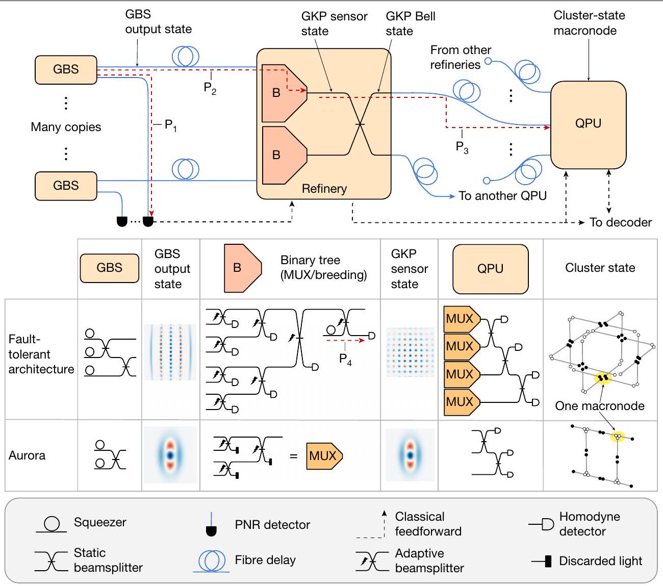
الشكل 1 | تخطيط المعمارية بما في ذلك مسارات الخسارة و . الأعلى: مخطط لهندستنا. يتم توليد سوابق حالات GKP من حالات غاوس المتعددة الأنماط التي يتم إنتاجها بشكل احتمالي باستخدام شرائح GBS من خلال الإشارة إلى أنماط PNR معينة. يتم إرسال العديد من حالات السابِق إلى كل شريحة تكرير (عبر تأخيرات الألياف الضوئية الممثلة بالخطوط الزرقاء)، والتي تستخدم مزيجًا من التعدد والتربية المنفذة في شجرة ثنائية من مقسمات الشعاع (الممثلة بالأشكال الشبيهة بالوتد المسمى ‘B’)، والضغط، لإنشاء زوج من حالات مستشعر GKP عالية الجودة. بالنسبة للهندسة المعمارية المقاومة للأخطاء، يتم تعزيز الشجرة الثنائية بكاشفات هوموداين. ثم يتم توليد زوج بيل من خلال تطبيق مقسم الشعاع (خطوط صلبة سوداء). إن التوجيه المكاني والتأخيرات الزمنية للأوضاع في كل زوج هي تم تعيينه بواسطة رسم حالة العنقود المرغوب، بحيث يتوافق كل ماكرونود في الرسم البياني مع شريحة QPU فردية وتشارك هذه الشرائح أزواج متشابكة إذا كانت جيرانًا في رسم حالة العنقود. في الهيكل المعتمد على مقاومة الأخطاء، يتم إنشاء أزواج متعددة لكل حافة، ولكن يتم اختيار زوج واحد فقط لكل حافة رسم بياني بواسطة جهاز اختيار متعدد في بداية QPU. ثم، يتداخل كل QPU مع الأزواج المختارة باستخدام مقسمات شعاعية ثابتة ويتم قياس هذه الأنماط باستخدام الكشف الهوموديني. يتم إظهار مسارات الفقدان بخطوط حمراء متقطعة بينما يتم تمثيل التغذية الراجعة الكلاسيكية بخطوط سوداء متقطعة. في المنتصف: جدول يوضح الهيكل الداخلي لكل وحدة فرعية في الهيكل المعتمد على مقاومة الأخطاء وفي تجربة أورورا. في الأسفل: مفتاح لرسوم مكونات بصرية. مع الاتصال غير المحلي هو أمر بسيط، مما يجعل هيكلنا متوافقًا مع رموز LDPC ذات المعدل الأعلىلضمان التشابك المستمر بين مواقع الكيوبت في فترات الساعة المتجاورة – المطلوبة للحساب الكمومي القائم على القياس – يتعرض مجموعة من أزواج بيل لتأخير زمني في أحد أوضاعها باستخدام خط تأخير بصري. يتم توليد عدة أزواج بيل GKP لكل حافة شبكة الحالة العنقودية، مع إرسال الوضعين من كل زوج إلى خلايا QPU. كل من خلايا QPU، التي تم ترتيبها في مصفوفات على مجموعة أخرى من الرقائق الضوئية، تتوافق مع موقع شبكة الحالة العنقودية، أو العقدة الكبيرة.; هذه المواقع بدورها تتوافق مع الكيوبتات الفيزيائية المتاحة للحساب. توفر المرحلة الأولى من شرائح QPU طبقة نهائية من التبديل، حيث يتم اختيار أفضل زوج لكل حافة شبكية للاستخدام بواسطة شجرة ثنائية صغيرة؛ يتم إجراء هذا الاختيار بناءً على نتائج الكشف الهوموديني في المصفاة، ونتائج عد الفوتونات من خلايا GBS. يتم أخيرًا إخضاع أزواج بيل المختارة، داخل كل خلية QPU، إلى محولات الطور التي تنفذ بوابات هادامارد GKP، مما يحولها إلى حالات عنقودية من الكيوبتات الثنائية، ثم تسلسل قصير من مقسمات الحزم الثابتة وقياسات هوموديني التي تسقط هذه المدخلات على حالات GHZ.لإنشاء حالة العنقود المتصل بالكامل المطلوبةتُختار قواعد القياس في كل دورة ساعة بواسطة وحدة تحكم تقليدية تُبلغها كل من الخوارزمية المحددة من قبل المستخدم وبروتوكول تصحيح الأخطاء (بما في ذلك جهاز فك التشفير)، مع الأخذ في الاعتبار نتائج القياس من خطوات الوقت الحسابية السابقة. يتم تحقيق الشمولية الكاملة مع الحالات السحرية المشفرة في شفرة GKP والمضمنة في إنشاء الأزواج.أو تم إنشاؤه من خلال القياسات على حالة العنقودلا يُتوقع أن تؤدي مثل هذه العملية في توليد الحالة السحرية إلى تفاقم تحمل الخسائر في هيكلنا، ولكن هناك حاجة إلى مزيد من العمل للتحقق من ذلك بشكل قاطع.
تجربة
تعتمد الهندسة المعمارية الموصوفة على أربع وظائف رئيسية، يجب تنفيذها جميعًا في منصة متكاملة وقابلة للتوسع إلى ما لا نهاية لتوفير حاسوب كمومي مقاوم للأخطاء دون قيود جوهرية في عدد الكيوبتات. هذه الوظائف هي: (1) التركيب المعلن للحالات غير الغاوسية باستخدام كواشف حساسة لعدد الفوتونات، (2) تفعيل التغذية الراجعة في الوقت الحقيقي لأشجار ثنائية من مقسمات الشعاع بناءً على أحداث هذه الكواشف، (3) تشابك مخرجات هذه الأشجار لتشكيل حالة عنقودية زمانية مكانية، و(4) قياسات رباعية يتم تنفيذها على جميع عقد الحالة العنقودية في كل فترة زمنية، تُغذى إلى جهاز فك التشفير المنفذ في الوقت الحقيقي، مع توفر تغذية راجعة بدورة ساعة واحدة لإبلاغ قواعد القياس اللاحقة باستخدام نتائج القياسات السابقة. لإثبات الجدوى التكنولوجية لهذا النهج، قمنا ببناء
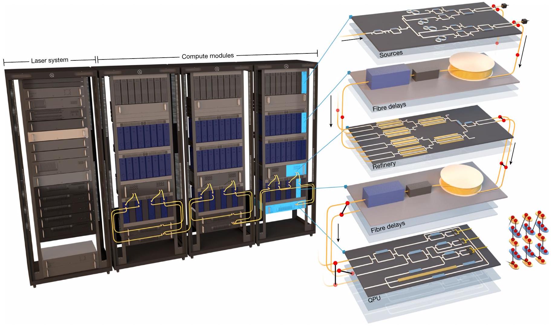
الشكل 2| مخطط تخطيطي لنظام أورورا والوحدات الرئيسية. تولد مجموعة من 24 شريحة مصدر حالات مضغوطة وحالات غاوسية متشابكة ذات وضعين. يتم ضخها بواسطة نظام ليزر نبضي مخصص (الرف الأيسر)، الذي يولد أيضًا ويوزع أشعة المذبذب المحلي وأشعة المرجع لتثبيت الوحدات الحاسوبية. تُستخدم كواشف PNR على نصف كل من مخرجات حالة غاوسية ذات وضعين من هذه الشرائح (المصادر) للإعلان عن حالة غير غاوسية؛ بينما تنتظر نتائج الكشف، يتم تخزين الوضع الآخر بواسطة خط تأخير ألياف مستقر (تأخيرات الألياف). تُغذى المخرجات المعلنة إلى مجموعة من ست شرائح تكرير (التكرير)، حيث يتم تنشيط كل منها ديناميكيًا لاختيار أفضل زوج متاح من المدخلات باستخدام زوج من مضاعفات شجرة ثنائية من أربعة إلى واحد لتوليد زوج بيل متشابك. تتوفر ستة أزواج من هذا القبيل بعد التكرير؛ يتم تأخير نصف زوجين، من خلال وحدات التوجيه (تأخيرات الألياف)، لتوليد التشابك.
نموذج لهذه البنية (الموضح في الشكل 1، باستخدام المكونات المدرجة في صف ‘أورورا’ من الجدول) يتضمن جميع هذه الميزات الوظيفية في منصة معيارية قابلة للتوسع إلى ما لا نهاية. تستضيف هذه الآلة نظام مصادر يحتوي على 84 ضاغطًا ضمن 42 خلية GBS، موزعة عبر مجموعة من 21 PICs من نيتريد السيليكون (بالإضافة إلى 3 إضافية للنسخ الاحتياطي)، مما يوفر 12 حالة مضغوطة و36 حالة غير غاوسية مُعلنة باستخدام 36 كاشف PNR. تغذي المخرجات 48 مدخلًا إلى مجموعة تكرير تحتوي على 12 شجرة تبديل ثنائية عبر 6 PICs من مكرر الليثيوم-niobate رقيقة الفيلم، كل منها ينتج زوجًا متشابكًا من نوع بيل. الأوضاع التي تتكون منها هذه الأزواج، بعد تأخير زمني مناسب على مجموعة فرعية، تتشابك في حالة عنقودية وتقاس في كل دورة ساعة بواسطة خمسة شرائح QPU (من خلال الطريقة الموضحة في المرجع 37)، المنفذة على PICs من السيليكون، والتي تتفاعل في الوقت الحقيقي مع فك تشفير كلاسيكي تم تنفيذه على مصفوفة بوابة قابلة للبرمجة. يتم تقديم مخطط الآلة في الشكل 2 ويتم وصفه بالتفصيل الكامل في المعلومات التكميلية. يتناسب النظام بالكامل في أربعة رفوف خادم قياسية تحتوي على وحدات معبأة بالكامل تعمل في درجة حرارة الغرفة، باستثناء نظام كشف PNR، الذي يتم وضعه في جهاز تبريد. جميع وحدات PIC متصلة بشبكة باستخدام وحدات خط تأخير الألياف المخصصة المستقرة في الطور والاستقطاب لنقل الضوء الكمي بين المراحل وتشابك الأوضاع بشكل مناسب على شرائح QPU منفصلة لتمكين تخليق الحالة العنقودية. بين فترات الساعة المتجاورة. ثم يتم تجميع جميع الأزواج في حالة عنقودية زمانية مكانية بواسطة مجموعة من 5 شرائح QPU، التي تقوم أيضًا بإجراء قياسات هوموداين على جميع الأوضاع التشغيلية الـ 12 في كل دورة ساعة. وبالمثل، يقوم كل شريحة QPU بتنفيذ قياس GHZ متعدد الأوضاع، مما يولد حالة موارد متصلة بالكامل. نمط توجيه الألياف بين المصفاة و QPUs، الموضح بواسطة الكابلات الصفراء في أسفل الرفوف، ينفذ شبكة حالة العنقودية المرغوبة من خلال ربط QPUs بشكل مناسب. للتوضيح، لم يتم عرض مسارات كابلات الألياف الأخرى، من نظام الليزر إلى نظام الحوسبة ومن وحدات المصادر إلى PNRs أو إلى مدخلات المصفاة عبر خطوط التأخير. يمكن العثور على تفاصيل مخطط الأجهزة الكامل للنظام، ونظام الليزر والوحدات في الأشكال التكميلية 22 و 24 و 30-33، على التوالي.
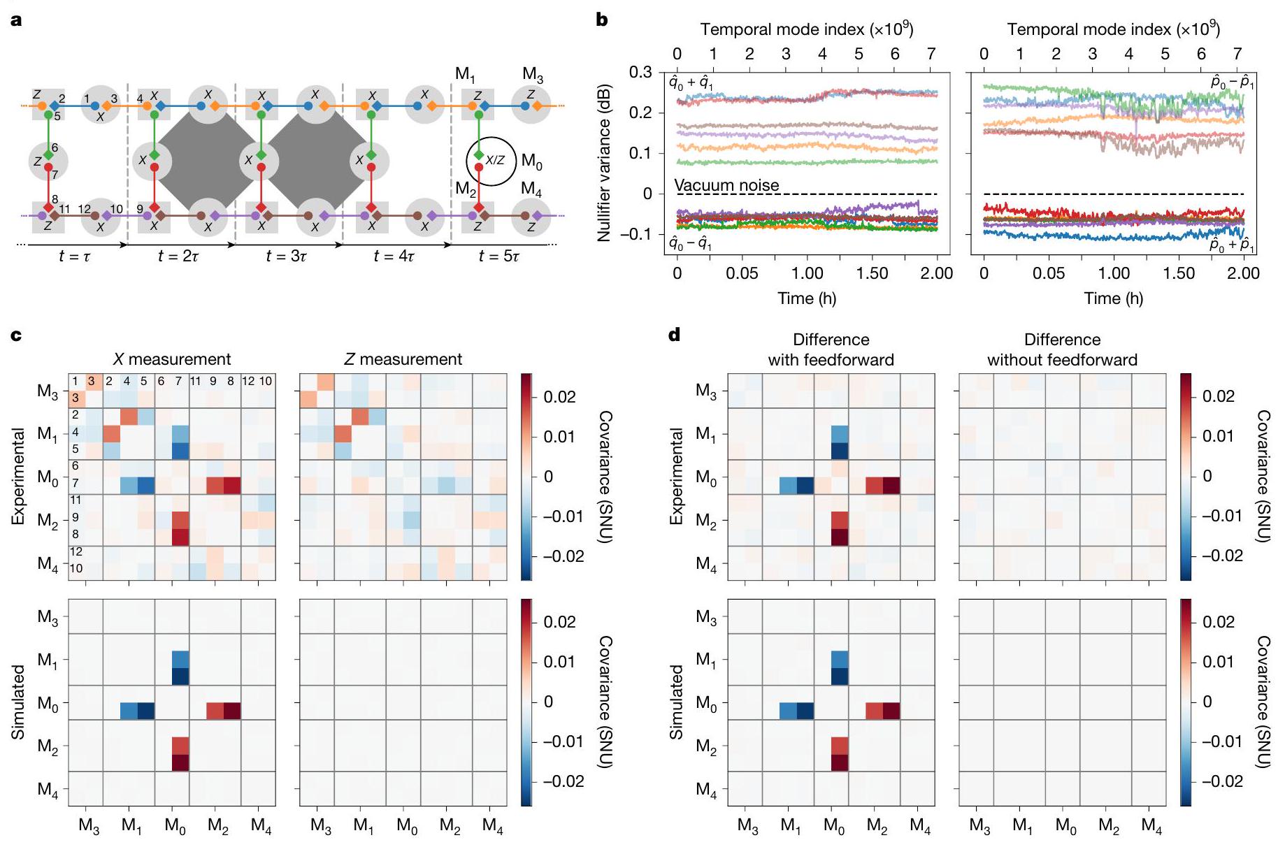
لقياس الوظائف الرئيسيةالمذكور أعلاه،تم إجراء التجارب الأساسية باستخدام الآلة. أولاً، تم برمجة النظام لتمرير الحالات المضغوطة فقط إلى مصفوفة وحدة المعالجة الكمية (بدلاً من مخرجات الحالة غير الغاوسية المعلنة) وبالتالي توليف حالة العنقود الغاوسي -الوضع، حيثهي مدة التجربة في فترات الساعة. تختبر هذه المعلمة جميع المكونات الوظيفية للنظام باستثناء ميزات التغذية الأمامية واكتشاف PNR. يمكن تبسيط وصف حالة المورد المعدة باستخدام الطرق الموضحة في المرجع 37 من خلال إعادة تطور الأوضاع المقاسة عبر وحدة QPU (المعروفة أيضًا بالتعبير عن الحالة من حيث أوضاعها الموزعة). )، مما يؤدي إلى أزواج مترابطة مرتبة كما هو موضح في الشكل 3a. يتم ربط الماكرونودات المجاورة إذا كانت الزوج الذي يربطها غير قابل للفصل. النتائج (تباينات المحايد) موضحة في الشكل 3b، مرسومة كدالة لمؤشر وضعها الزمني. تم الحصول على هذه النتيجة بشكل مستمر على مدى ساعتين، وتمثل تركيب وقياس حالة مجموعة ماكرونود تتكون من 86.4 مليار وضع، أو مليار وضع زمني. على الرغم من الخسائر البصرية العالية التي تبلغ حوالي 14 ديسيبل من تركيب الحالات المضغوطة إلى اكتشافها النهائي في وحدة المعالجة الكمية، فإن هذه التباينات تظل باستمرار دون مستوى ضوضاء الفراغ، مما يشير إلى الضغط ويؤكد على التشابك الموجود في العنقود بين كلا الوضعين اللذين يشكلان كل زوج. درجة
الشكل 3| تخليق وقياس حالة تجمع العقد الكبيرة. أ، تمثيل بياني لحالة تجمع الـ 12 وضعية. لكل نافذة زمنيةتتداخل الأزواج (نقاط ملونة مرتبطة بخط صلب) عبر الماكرونودات المجاورة. يتم توفير تسميات الوضع (الماكرونود) في الخطوة الزمنية الأولى (الخامسة) و هو فترة ساعة التجربة. يمكن برمجة قياس واحد هوموداين لكل ماكرونود، بينما يتم قياس البقية في . لأزواج الوضع و وضع واحد تم تأخيره زمنياً، مما يسمح بالحساب والتشابك بالاستمرار في الزمن.وتمثل مشغل موضع الزخم ومشغل الزخم، على التوالي. ب، تباينات المحايدين مقابل الزمن. من خلال تطبيق التحويل الخطي العكسي لشبكة مقسم الأشعة الماكروية على نتائج الزخم المقاسة، حصلنا على قيم الزخم التي تتوافق مع ستة أزواج متشابكة فردية قبل التداخل المتبادل. المحايدون لهذه الحالات (الخطوط الصلبة) هم من الشكل(اللوحة اليسرى) و(اللوحة اليمنى). يتم الحفاظ على تباينها تحت ضوضاء الفراغ على مدى اكتساب مستمر لمدة ساعتين (يتوافق مع 86.4 مليار وضع، ناتج 7.2 مليار وضع زمني على 12 وضع مكاني) بمعدل ساعة قدره 1 ميجاهرتز. المشغلون(اللوحة اليسرى) و(اللوحة اليمنى) هم مشغلون يتعلقون بالاتجاهات المضادة للضغط لحالة الضغط ثنائية الوضع، وتم ملاحظة تباينها
(الخطوط الخفيفة) فوق ضوضاء الفراغ طوال مدة الاكتساب. ج، القدرة التكيفية. تشير التسمياتوفي أ إلى قاعدة قياس لقياس هومودين القابل للبرمجة في كل ماكرونود، تتوافق معأو أي منهما، على التوالي. نمط القياس هذا يقيس مشغلين للتحقق من رمز التكرار رباعي الجسم (بدعم على الماس المظلم الرمادي في أ). يتم تكرار نمط القياس هذا ويتم جمع بيانات هومودين لـ 12 وضع في كل خطوة زمنية خامسة. يتم بناء مصفوفات التغاير المنفصلة من البيانات عندما يتم قياس الوضعفي(اليسار) مقابل(اليمين). يتم وضع تسميات على صفوف وأعمدة المصفوفة لتعكس ترقيم الأوضاع في أ. تم إزالة تباين الوضع الفردي على القطرات لتحسين التباين، بينما يتم رسم قيم التغاير بوحدات ضوضاء اللقطة (SNU)، الوحدات التي يكون فيها الفراغ له تباين قدره 1 و. د، تجربة التحكم. الفرق بين مصفوفات التغاير التي تتوافق مع قاعدة قياس– و– قرار فك التشفير الموضح في ج (اليسار، ‘مع التغذية الراجعة’)، ومن تجربة متطابقة بخلاف ذلك حيث يتم تحديد القاعدة المقاسة عن طريق الاختيار العشوائي بدلاً من قرار فك التشفير (اليمين، ‘بدون تغذية راجعة’).
يتفق ضغط المحايدين جيدًا مع المحاكاة العددية للجهاز.
لإظهار قدرات التغذية الراجعة وتوليف الحالة غير الغاوسية لجهازنا، تم إجراء تجربة كشف خطأ رمز التكرار على حالات GKP منخفضة الجودة. تم الإبلاغ عن اكتشاف فوتونين في وضع الإبلاغ GBS، وتوجد مخرجات خلايا GBS في حالات قطة مضغوطة ذات توازن زوجي تقارب بشكل خشن حالات مستشعر GKP ذات قمتين بسيطة. عند الفشل في ملاحظة فوتونين، يتم اختيار حالة مضغوطة بواسطة الموزع، بحيث تكون الأوضاع الناتجة في مجموعة من الحالات المضغوطة وحالات القطة المضغوطة – الأخيرة تشكلفي المتوسط من الأوضاع. هذه نادرة بما يكفي بحيث لا تعتمد نتائجنا على تضمينها؛ النتائج متطابقة تقريبًا إذا تم استخدام حالات مضغوطة فقط. نقوم بتهيئة حساب يقوم بإجراء رمز تكرار (مصفوفة)
التحقق (من خلال القياسات في خطوات زمنيةفي الشكل 3 أ). يتم معالجة النتائج بواسطة فك تشفير QPU، الذي يحسب قيم البت وتقديرات احتمالات خطأ الطور المرتبطة بالكيوبتات المعنية في تحقق التوازن، والتي تستخدم بدورها في فك تشفير انتشار الاعتقاد. يقوم فك التشفير بإخراج توزيع محدث لاحتمالات الخطأ المستخدمة لتحديد الثقة في الاسترداد. نطبق دالة عتبة على قيمة الثقة لتحديد أي قاعدة يجب قياسها في خطوة الزمن التالية – إذا تم تأسيس الاسترداد بثقة عالية (منخفضة)، يتم قياس الماكرونودفي خطوة الزمن 5 في قاعدة. تؤدي دالة العتبة إلى اختياروكـومن الوقت، على التوالي. يمكن ملاحظة تأثير عملية التغذية الراجعة من خلال مقارنة الارتباطات الموجودة في بيانات الهومودين من الأوضاع في خطوة الزمن الخامسة بينوالحالات المختارة (الشكل 3 ج). نقوم بقياسعلى الماكرونودات
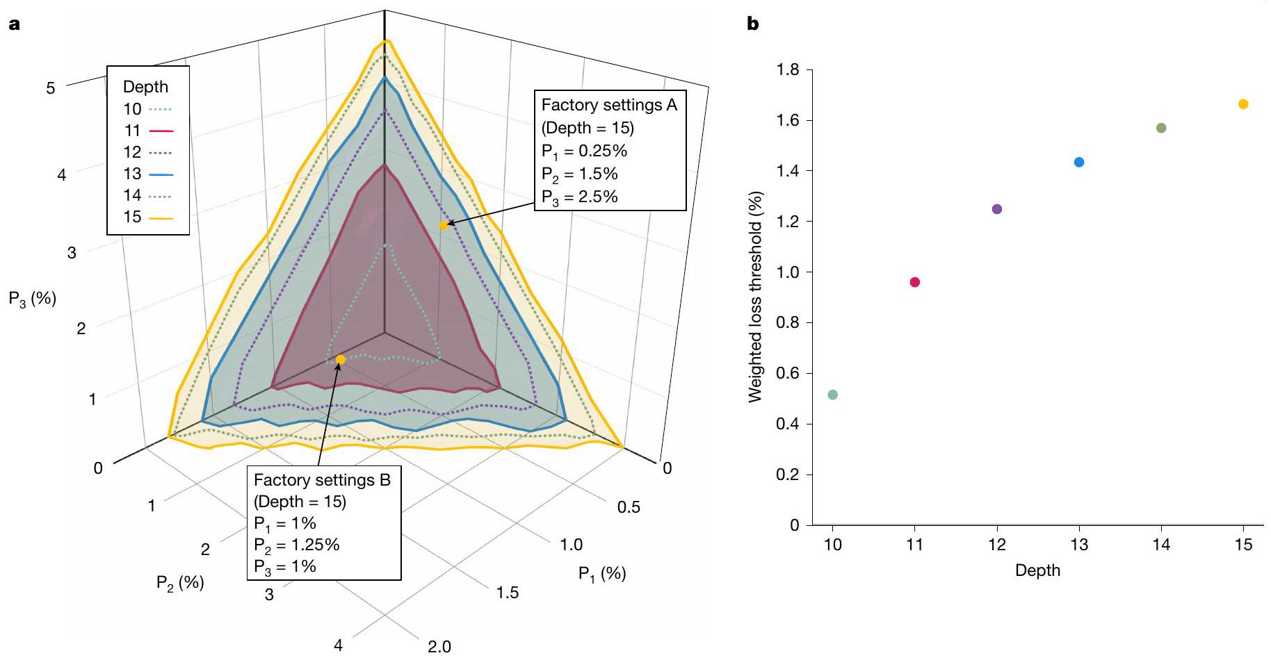
الشكل 4 | عتبة تحمل الأخطاء. أ، ميزانية الفقد وعمق التعدد المطلوب للتشغيل المقاوم للأخطاء. نقوم بتحليل تحمل الفقد على طول المسارات الثلاثةوكوظيفة للعمق المشترك لأشجار المقسمات المتوازنة في مصفوفات التكرير ورقائق QPU الموضحة في الشكل 1. بالنسبة لتكوينات الهندسة المعمارية مع عمق مشترك معين، يتم رسم الأسطح التي تم ملاءمتها لأقصى قيم تحملولذا، يمثل كل نقطة على سطح معين مجموعة من ميزانيات الفقد بافتراض عمق إجمالي ثابت للمسارات البصرية الثلاثة الرئيسية في النظام لتلبية متطلبات تحمل الأخطاء. النقاط الصفراء الاثنتان تتوافقان
مع زوج من تكوينات المثال مع أعماق مشتركة للتكرير وQPU قدرها 15. ب، عتبة الفقد الموزونة والعمق. يؤثر تغيير العمق على مسافة الأسطح في أ من الأصل. لكل عمق، نقوم برسم عتبة الفقد الموزونة، المحددة بأنها متوسط طول المكون لجميع نقاط بيانات السطح في اتجاه متجه عادي تقريبي. يتم العثور على المتجهمن خلال بناء متجهات عادية أولاً للطائرات المحددة بواسطة النقاط الثلاثة ‘الزاوية’ القصوى لكل سطح، ثم أخذ المتوسط. يتم تقديم تحليل تكوينات الهندسة المعمارية مع GBS ثنائية الوضع في المعلومات التكميلية. وتقييد اثنين من الأثقال، الأوضاعوأوضاعفي الشكل 3 أ، لتكون دائمًا حالات غاوسية بحيث تكون بيانات الزخم لها هيكل أبسط وأكثر تميزًا. إذا لم يكن من الممكن إكمال قراءة القياس وفك التشفير في الوقت المناسب للخطوة الخامسة في البروتوكول، فلن يتم اختيار القاعدة بشكل صحيح مع احتمالات أفضل من حواليعشوائي. يمكننا محاكاة ذلك في إعدادنا من خلال تكرار البروتوكول مع قاعدةفي خطوة الزمن الخامسة المختارة بواسطة متغير عشوائي ثنائي غير مرتبط بقرار فك التشفير. إذا تم رسم الارتباطات الهومودينية مرة أخرى بناءً على قرار فك التشفير، فيجب أن تظهر هذه المرة متطابقة. نقوم برسم الفرق بين مصفوفات التغاير المحددة بواسطة نتائج فك التشفير لسيناريوهات التغذية الراجعة وعدم التغذية الراجعة في الشكل 3 د.
متطلبات الفقد
بالعودة إلى الهندسة المعمارية الكاملة المقترحة، نلاحظ أن تحمل الأخطاء في أي هندسة ضوئية يعتمد بشكل كبير على فقدان الفوتونات، والذي يوجد في جميع الوحدات الفرعية البصرية والمكونات في الشكل 1. يُلاحظ أنه يمكن دمج قنوات الفقد المتسلسلة (يتلاشى الانتقال بشكل مضاعف) ويفقد الفقد الموحد على طول مسارات متعددة مع التحولات البصرية الخطية. وبالتالي، يمكن تحويل مساهمات الفقد إلى قناة أحادية الوضع تعمل على جميع الأوضاع بشكل مستقل، ويمكن أن يتم ذلك قبل عد الفوتونات أو كاشفات الهومودين، أو أي نقطة أخرى مختارة في المسار. نقوم بتعريف ثلاث مسارات بصرية رئيسية: ، من الضاغط إلى عداد الفوتونات، ، من الضاغط إلى الهومودين في التكرير، ومن مخرج MUX وشجرة التكاثر في التكرير إلى ما قبل كاشفات الهومودين في QPU مباشرة. بهذه الطريقة، يمكن حساب فقدان أطول مسار من خلال دمجو
fقدان (بافتراض أن فقدان الكاشف في التكرير يساوي تلك الموجودة في QPU). نقوم أيضًا بتعريف مسار الفقد الثانوي، للوضع المستخدم في الضغط القائم على القياس. يتم عرض هذه المسارات الفقد في الشكل 1. من خلال دمج الفقد ذات الصلة بشكل مناسب، يمكن التقاط آثارها بالكامل من خلال أرقام الجدارة المرتبطة بوحدات زوج GKP Bell التي تشكل الوحدات الأساسية للهندسة المعمارية. يمكن قياس جودة الكيوبتات GKP التقريبية من خلال مدى فعاليتها ككيوبتات فعلية للطبقة التالية من تصحيح الأخطاء الكمومية. نقوم بذلك من خلال ربط الضغط الفعال المتماثل (انظر المعلومات التكميلية لوصف) بمتطلبات الضغط لتحمل الأخطاء لرمز السطح المدمج مع رمز GKP. نقوم بإجراء تحسين شامل لمختلف ‘مصانع الحالة’ المرشحة – المجموعات من العناصر التي توفر أفضل أزواج بيل GKP المتاحة ليتم تشابكها في حالة عنقودية – ونقدم النتائج في الشكل 4، حيث يتم تصور عتبة تحمل الأخطاء بالنسبة للخسارة الموجودة في المسارات البصرية الثلاثة الرئيسية في الهيكل. يتم تقديم تفاصيل هذا التحسين في الطرق. لتسهيل التصور،غير ممثل. ومع ذلك،تتضمن مجموعة صغيرة من العناصر التي تم تجربتها في، ومتطلبات خسارتها أقل صرامة من أي من؛ وبالتالي إذا كانت حدود الخسارة المعروضة لتلك المسارات قابلة للتحقيق، يجب أن تكون حدود الخسارة لـ. يمثل كل مستوى عمقًا إجماليًا ثابتًا (عمق شجرة المصفاة بالإضافة إلى عمق شجرة QPU)، ويفصل المنطقة (في فضاء معلمات الخسارة) المتوافقة مع التشغيل المقاوم للأخطاء، الأقرب إلى الأصل، عن تلك الخاصة بالتشغيل فوق العتبة. وهذا يضع حدودًا دنيا واضحة، بالنسبة للهندسة المعمارية المدروسة، على مقدار الخسارة التي يمكن تحملها في المكونات التي تشكل كل مسار بصري، مع الأخذ في الاعتبار قيد (يفرضه متطلبات الهندسة والتكلفة) على عدد خلايا GBS ومدخلات شريحة المصفاة القصوى المسموح بها. لكل كيوبت مادي. بدوره، يوفر هذا معايير يمكن من خلالها تقييم خيارات الأجهزة – مثل مواد الموجات الدائرية، ونظم ربط الرقائق بالألياف، وتصميمات المكونات.
المناقشة والتطلعات
على الرغم من أن العروض التوضيحية لأنظمة مثل أورا تساعد في بناء الثقة في قابلية توسيع النهج الضوئي للحوسبة الكمومية، لا يزال هناك فجوة – كما هو الحال مع جميع النهج المادية – بين الأداء الحالي ومتطلبات تحمل الأخطاء. على الرغم من أن التحسينات ضرورية لنقل الوحدات المسؤولة عن تخليق ومعالجة الكيوبتات من النماذج الأولية إلى التصنيع الضخم، تشير نتائجنا إلى أن الخلفية التكنولوجية الحالية لتصنيع الرقائق الضوئية، والإلكترونيات التحكم الكلاسيكية، والشبكات البصرية الليفية تجعل من الممكن مهمة تجزئة وتوسيع بنية ضوئية واقعية للحوسبة الكمومية القابلة لتحمل الأخطاء. بالإضافة إلى ذلك، فإن الأسس النظرية البصرية الكمومية قد تم تطويرها الآن بشكل كافٍ لتمكين تحسين شامل للهياكل المعتمدة على GKP البصرية للعثور على تلك الأكثر كفاءة في الأجهزة وقادرة على تحمل العيوب الفيزيائية.
ومع ذلك، فإن فجوة أداء المكونات كبيرة: في حين أن التكوينات المثلى المعروفة حاليًا تتطلب حواليميزانيات الخسارة والتحدي حول 10 أعماق تعدد الإرسال لتحقيق تشغيل مقاوم للأخطاء، تظهر أورا خسائر تبلغ حواليلطرق البشارة )، وأعلى قليلاً من للمسارات البصرية المعلنة و ). في الواقع، تم بناء هذا النظام لإظهار قابلية توسيع النهج من خلال التعديل والشبكات. على الرغم من إجراء العديد من دورات التصميم الشاملة واختيار ما بعد التصنيع، لم يتم إجراء أي تحسينات خاصة على فقدان الطاقة على منصات الرقائق المستخدمة، والتي كانت جميعها تعتمد على خطوط تصنيع تجارية متاحة مسبقًا.
تحمل الخسارة في الشكل 4 ليست حدودًا قصوى صارمة، بل هي حدود دنيا قابلة للتحقيق بواسطة دوائر محددة؛ هنا، قصرنا أنفسنا على عائلة منظمة مستمدة تحليليًا من مصادر GBS، وتربية حالة القطط التكيفية كبروتوكول تكرير، وطريقة معينة لبناء حالات العنقود. تحمل الخسارة للمسارات، و يمكن زيادة ذلك وتقليل أعماق الدوائر لرقائق التكرير وQPU من خلال تحسين إضافي للبروتوكولات النظرية، على الرغم من أننا نتوقع أن تظل هذه التسامحات في الخسارة ضمن ترتيب واحد من الحجم للنطاقات التي يتم النظر فيها حاليًا. يمكن تحقيق ذلك، على سبيل المثال، من خلال استخدام دوائر GBS بديلة، وبروتوكولات تكرير أكثر تقدمًا، وبروتوكولات توليد حالات العنقود البديلة، وأكواد تصحيح الأخطاء الكمومية المصممة وفقًا للضوضاء جنبًا إلى جنب مع أكواد GKP غير المربعة أو المنحازة للضوضاء.والمشفّرات الأقرب إلى الأمثل، جميعها تستحق اهتمامًا مستقبليًا وقد تعدل حدود الخسارة لمسارات مختلفة بنسبة عدة نقاط مئوية.
من المتوقع أن يتطلب سد الفجوة بين الحالة الراهنة لأفضل التقنيات في مكونات الأجهزة وتلك المطلوبة لتحمل الأخطاء مساهمة من كل من تحسينات المعمارية وتحسينات الأجهزة. في هذا السياق، تُبذل جهود مكثفة في هندسة عمليات التصنيع المخصصة وتصميم المكونات الضوئية والألياف لتحقيق ميزانيات الفقد المطلوبة. نحن نلخص أحدث نتائجنا على مستوى المكونات نحو هذا الهدف لكل نظام فرعي ذي صلة في الطرق. عند النظر إليها بشكل مجمع، فإن تحسينًا بمقدار 20-30 مرة (عند قياسه على مقياس الديسيبل) في فقد الإدخال لكل مكون ضوئي مقارنةً بهذه الحالة الراهنة لأفضل التقنيات سيمكن من التشغيل القابل لتحمل الأخطاء حتى لو لم يتم إحراز أي تقدم إضافي في تخفيف المتطلبات المعمارية. التقارير الأخيرة عن تطوير المنصات لمكونات مماثلةلقد أظهرت أيضًا تقدمًا واعدًا في تقليل الخسائر.
بالإضافة إلى تحقيق أداء المكونات المتوافق مع تحمل الأخطاء، يجب تطوير طرق التصنيع لضمان إمكانية الحفاظ على هذه المستويات من الأداء في سياق الإنتاج الضخم. على سبيل المثال، آلة بعمق 12 (أي واحدة مع تحسين قدره 8 مرات في تكاليف المصنع مقارنةً بتلك التي تم اعتبارها في الشكل 4) مع 100 كيوبت منطقي وعبء تصحيح الأخطاء بنسبة 100 إلى 1، سيتطلب الأمر عشرات الملايين من خلايا GBS. حتى مع افتراض تحسين بمقدار 100 مرة في كثافة مكونات مصنع الحالة، سيتطلب ذلك عشرات الآلاف من رفوف الخوادم في مصنع الحالة؛ وإذا لم تكن جميع هذه التحسينات المفترضة ممكنة، فقد يكون هناك حاجة إلى المزيد. على الرغم من أن هذا ضمن نطاق مراكز البيانات الكلاسيكية الحالية، يجب أن يكون التقدم في أداء مكونات الفوتونيات الكمومية موجهًا بواسطة قيود تحترم هذه المتطلبات للتصنيع على نطاق واسع.
المحتوى عبر الإنترنت
أي طرق، مراجع إضافية، ملخصات تقارير Nature Portfolio، بيانات المصدر، بيانات موسعة، معلومات إضافية، شكر وتقدير، معلومات مراجعة الأقران؛ تفاصيل مساهمات المؤلفين والمصالح المتنافسة؛ وبيانات توفر البيانات والرموز متاحة علىhttps://doi.org/10.1038/s41586-024-08406-9.
برافي، س. وآخرون. ذاكرة كمومية مقاومة للأخطاء ذات العتبة العالية والتكاليف المنخفضة. ناتشر 627، 778-782 (2024).
بايتزنيك، أ. وآخرون. عرض الكيوبتات المنطقية وتصحيح الأخطاء المتكرر بمعدلات خطأ أفضل من المعدلات الفيزيائية. مسودة فيhttps://arxiv.org/abs/2404.02280 (2024).
جوجل كوانتوم إيه آي. قمع الأخطاء الكوانتية من خلال توسيع كود السطح للكيوبت المنطقي. ناتشر 614، 676-681 (2023).
بلوفشتاين، د. وآخرون. معالج كمي منطقي يعتمد على مصفوفات الذرات القابلة لإعادة التكوين. ناتشر 626، 58-65 (2024).
تشانغ، ي. وآخرون. ضوء مضغوط من جزيء نانوفوتوني. نات. كوميونيك. 12، 2233 (2021).
مينيتشوتشي، ن. س. حالات العنقود المستمرة في الوضع الزمني باستخدام البصريات الخطية. فيز. ريف. أ 83، 062314 (2011).
بريسكيل، ج. الحوسبة الكمومية في عصر NISQ وما بعده. كوانتم 2، 79 (2018).
شور، ب. و. خوارزميات للحساب الكمومي: اللوغاريتمات المنفصلة والتحليل. في وقائع الندوة السنوية الخامسة والثلاثين حول أسس علوم الحاسوب 124-134 (IEEE، 1994).
أليكسييف، ي. وآخرون. الحوسبة الفائقة المركزية على الكم لعلوم المواد: منظور حول التحديات والاتجاهات المستقبلية. أنظمة الحوسبة المستقبلية 160، 666-710 (2024).
مكاركل، س.، إندو، س.، أسبورو-غوزيك، أ.، بنجامين، س. سي. ويوان، إكس. الكيمياء الحاسوبية الكمية. مراجعة الفيزياء الحديثة 92، 015003 (2020).
غيدني، سي. وإكيرو، م. كيفية تحليل أعداد RSA بحجم 2048 بت في 8 ساعات باستخدام 20 مليون كيوبت مشوش. كوانتم 5، 433 (2021).
دالزيل، أ. م. وآخرون. خوارزميات الكم: استعراض للتطبيقات والتعقيدات من البداية إلى النهاية. مسودة مسبقة فيhttps://arxiv.org/abs/2310.03011 (2023).
أهارونوف، د. وبن-أور، م. حساب كمي مقاوم للأخطاء مع خطأ ثابت. في وقائع الندوة السنوية التاسعة والعشرين لجمعية الحاسبات الأمريكية حول نظرية الحوسبة 176-188 (جمعية الحاسبات الأمريكية، 1997).
دويفنوردن، ك.، تيرهال، ب. م. وويغاند، د. مستشعر إزاحة أحادي الوضع. فيز. ريف. أ 95، 012305 (2017).
Walshe, B. W.، Baragiola, B. Q.، Alexander, R. N. & Menicucci, N. C. النقل البوابي للمتغيرات المستمرة وتصحيح أخطاء الشيفرة البوزونية. Phys. Rev. A 102، 062411 (2020).
Walshe, B. W.، Alexander, R. N.، Menicucci, N. C. & Baragiola, B. Q. الحوسبة الكمومية المبسطة باستخدام حالات تجمع الماكرونود. فيز. ريف. A 104، 062427 (2021).
ريتشاردسون، ت. وأوربانك، ر. نظرية الترميز الحديثة (مطبعة جامعة كامبريدج، 2008).
مارك، ب. طبيعة الحالة الأساسية والانضغاط غير الخطي لحالات غوتسمان-كيتايف-بريسكل. فيز. ريف. ليت. 132، 210601 (2024).
ملاحظة الناشر: تظل شركة سبرينغر ناتشر محايدة فيما يتعلق بالمطالبات القضائية في الخرائط المنشورة والانتماءات المؤسسية.
الوصول المفتوح هذه المقالة مرخصة بموجب رخصة المشاع الإبداعي النسبية-غير التجارية-بدون اشتقاقات 4.0 الدولية، والتي تسمح بأي استخدام غير تجاري، ومشاركة، وتوزيع، وإعادة إنتاج في أي وسيلة أو صيغة، طالما أنك تعطي الائتمان المناسب للمؤلفين الأصليين والمصدر، وتوفر رابطًا لرخصة المشاع الإبداعي، وتوضح إذا قمت بتعديل المادة المرخصة. ليس لديك إذن بموجب هذه الرخصة لمشاركة المواد المعدلة المشتقة من هذه المقالة أو أجزاء منها. الصور أو المواد الأخرى من طرف ثالث في هذه المقالة مشمولة في رخصة المشاع الإبداعي الخاصة بالمقالة، ما لم يُشار إلى خلاف ذلك في سطر الائتمان للمادة. إذا لم تكن المادة مشمولة في رخصة المشاع الإبداعي الخاصة بالمقالة واستخدامك المقصود غير مسموح به بموجب اللوائح القانونية أو يتجاوز الاستخدام المسموح به، ستحتاج إلى الحصول على إذن مباشرة من صاحب حقوق الطبع والنشر. لعرض نسخة من هذه الرخصة، قم بزيارةhttp://creativecommons.org/licenses/by-nc-nd/4.0/. (ج) المؤلف(ون) 2025
طرق
يتكون نظام الأجهزة أورا (الشكل البياني الممتد 1) من ستة أنظمة فرعية رئيسية متميزة: (1) نظام ليزر رئيسي مخصص يوفر أشعة مضخة متماسكة وأشعة مذبذب محلي، بالإضافة إلى أشعة مرجعية لتثبيت الطور؛ (2) مجموعة مصادر تولد ضوءًا مضغوطًا وحالات غاوسية ثنائية الوضع؛ (3) يتم استخدام نظام كشف PNR للإعلان عن حالات غير غاوسية؛ (4) مجموعة من المصافي، كل منها يدمج ثمانية مدخلات إلى زوج واحد متشابك؛ (5) تشكل مجموعة QPU الاتصالات المكانية والزمنية في حالة العنقود وتقوم بإجراء قياسات هومودين على كل كيوبت؛ و(6) توفر مجموعة من مخازن الألياف خطوط تأخير مستقرة من حيث الطور والاستقطاب بين المصادر والمصافي، وكذلك بين المصافي و QPUs. يتناسب النظام بالكامل، باستثناء مجموعة الكشف الكريوجيني، في 4 رفوف خادم قياسية بحجم 19 بوصة. هنا نلخص الميزات الرئيسية لهذه الأنظمة الفرعية، بالإضافة إلى طريقتنا للتحقق من التشابك متعدد الأوضاع الموجود في تجربة معيار حالة العنقود لدينا؛ تتوفر تفاصيل أكثر عن هذه المواضيع في المعلومات التكميلية.
نظام الليزر
نظام الليزر مسؤول عن توفير نبضات ضخ مناسبة (P1 و P2) لكل ضاغط في مجموعة المصادر، وشعاع مذبذب محلي متطابق زمنياً مع النبضات الكمومية للكشف الهوموديني، ومجموعة متنوعة من الأشعة المرجعية المستخدمة لتثبيت تأخيرات الألياف (ref) ومواقع الرنانات (probe) في بقية النظام.
يبدأ نظام الليزر (الموضح في الشكل التوضيحي 24) بخمسة ليزرات ذات عرض خطي ضيق (P1، P2، المذبذب المحلي، المرجع والاستكشاف)، جميعها مصنعة بواسطة OEWaves (OE4040-XLN) باستثناء الليزر الاستكشافي، الذي صنعته PurePhotonics (PPCL550). يتم اشتقاق مجموعة ترددات كهربائية بصرية عريضة النطاق من ليزر المذبذب المحلي وتعمل كمرجع للتردد/الطور لتثبيت الأربعة ليزرات المتبقية. يتم تعديل كل ليزر بمعدل الساعة التجريبية البالغ 1 ميجاهرتز لتوفير أوضاع زمنية مناسبة لأغراضها: يتم تشكيل ليزرات الضخ إلى نبضات مدتها 1 نانوثانية (Exail MXER-LN-20، DR-VE-10-MO)، بينما يتم تشكيل ليزرات المرجع والاستكشاف إلى نبضات مدتها 400 نانوثانية (مع جهاز اختيار النبضات من AA Opto-Electronic) و50 نانوثانية (باستخدام Exail MXER-LN-20)، على التوالي، متداخلة مع نبضات الضخ في مرحلة لاحقة. يتم مطابقة وضع الغلاف الزمني المعقد لليزر المذبذب المحلي (باستخدام Exail MXIQER-LN-30) مع مخرج جهاز ضغط تمثيلي (تتم الإشارة إلى عملية الاختيار في المعلومات التكميلية). يتم تضخيم كل سلسلة نبضات إلى طاقة مناسبة باستخدام مضخمات الألياف المشوبة باليربيوم (نموذج Pritel MC-PM-LNFA-20) قبل دمجها في ألياف تحافظ على الاستقطاب (مع Opneti PMDWDM-1-1-CXX-900-5-0.3-FA). يتم تثبيت مراحل P1 وP2 وأشعة المذبذب المحلي مرة أخرى، قبل توزيعها بين مجموعتين من القنوات. تحتوي القناة الأولى، التي يوجد منها 24 نسخة، على P1 وP2 والاستكشاف والمرجع، ويتم إرسالها إلى مجموعة المصادر. تحتوي القناة الثانية، التي يوجد منها خمس نسخ، على المذبذب المحلي والمرجع، ويتم إرسالها إلى QPU للكشف المتماسك. نظرًا للطريقة التي يتم بها توزيع الأشعة، يحمل ليزر المرجع معلومات الطور في النظام وبالتالي يمكن استخدامه لتثبيت زوايا القياس في QPU. يتم إرسال نسخة ثانية من شعاع المرجع، متغيرة قليلاً في التردد، إلى مجموعة التكرير وتستخدم لتثبيت الاتصالات بين المصادر ومصفاة التكرير وكذلك بين مصفاة التكرير وQPU.
مصفوفة المصادر
كل من 24 شريحة مصدر متطابقة في التصميم، وتعتمد على منصة الموجات الضوئية من نيتريد السيليكون المقدمة من شركة Ligentec SA والمصنعة علىخط إنتاج التصنيع في X-Fab Silicon Foundries SE. تعتمد الضواغط في هذه الأجهزة على تصميم جزيء ضوئي، حيث يتم ضبط زوج من الرنانات الدقيقة لتمكين توليد الضوء المضغوط المتدهور باستخدام نظام مضخة مزدوجة، بينما يتم قمع العمليات غير الخطية الطفيلية غير المرغوب فيها من الدرجة العليا.تتميز الحالات المضغوطة الناتجة باستخدام التصوير الطيفي الهجين البصري وُجد أنها تقريبًا وضعية واحدة. يتم مطابقة وضع المذبذب المحلي الزمني مع الوضع الزمني السائد كما هو موضح في المعلومات التكميلية. يتم تمرير مخرجات المكثفات عبر مرشحات متكاملة من نوع ماخ-زنيدر غير المتناظرة لإزالة ضوء المضخة، ثم يتم تشابكها بواسطة مقياس تداخل بصري خطي قابل للتعديل. يتم ضبط مقياس التداخل والمرشحات والرنانات باستخدام محولات الطور الحرارية الضوئية. الشرائح هيفي الحجم، وهي معبأة بالكامل ومغلفة في حاوية معيارية تُركب على تجميع هيكل خلفي مخصص. خسارة الإدخال من النهاية إلى النهاية (من مدخل المضخة إلى الخرج الكمي) للرقائق هي 2.16 ديسيبل، وتتعرض الضوء الكمي لخسارة قدرها 1.82 ديسيبل من لحظة توليده إلى حين توفره في مخارج الألياف. تتضمن هذه القيمة كفاءة هروب الرنان الضاغط المقدرة بـ (نسبة الفلترة وفقدان انتشار المقياس التداخلي، وخسارة فصل الرقاقةكفاءة الاقتران.
تم تطوير تصاميم جديدة تعتمد على منصات ومكونات تصنيع مختلفة، على الرغم من عدم نشرها بعد في أورا، تجمع بين عدة طبقات من موجّهات السيليكون-نيتريد الرقيقة مع طبقة أكثر سمكًا محسّنة للتشتت، مما يمكّن من تقليل خسائر الربط بين الرقاقة والألياف بشكل كبير، وزيادة الضغط من خلال تحسين قمع العمليات غير الخطية الطفيلية. خسائر انتشار موجّهات الوضع الفردي تبلغ حواليلقد تم إثبات ذلك، مع وجود خسائر أقل حتى في مقاطع عرضية أوسع للمرنانات. كفاءات الهروب في هياكل الميكرو ريسوناتور الضاغطة التي تتجاوز 98% هي أمر روتيني، ولكن هناك حاجة إلى تحسينات إضافية في التصميم والتصنيع للحفاظ على عامل جودة محمّل مقبول تحت ظروف التزاوج القوي هذه. وبالمثل، تم ملاحظة اقتران الرقاقة بالألياف من هذه الأجهزة مع خسائر تبلغ حوالي 0.1 ديسيبل، مع محاكاة للهياكل المستقبلية تشير إلى أن الخسائر المنخفضة بشكل تعسفي ممكنة. هذه النتائج تتماشى مع تقارير التقدم الأخيرة في تطوير مكونات الفوتونيات الكمومية ذات الخسائر المنخفضة.حتى عند تحقيق ذلك، فإن الحفاظ على خسائر اقتران الرقائق والألياف المنخفضة خلال عملية التعبئة في خط إنتاج قادر على إنتاج الملايين من الرقائق اللازمة لتزويد الآلات ذات الفائدة العملية لا يزال يمثل تحديًا بارزًا.
نظام كشف رقم الحجز
نظام كشف PNR يعتمد على مجموعة من 36 مستشعر حافة الانتقال (TES)، housed in a pair of Bluefors (LD400) أجهزة تبريد تخفيف.درجة الحرارة الأساسية. يتم توصيل هذه المستشعرات بشكل تحريضي بمجموعة من أجهزة تداخل الكم الفائق التوصيل المتماسكة (SQUID) من أجل التضخيم الكريوجيني، حيث يتم رقمنة الإشارات وتحليلها في الوقت الحقيقي بواسطة مجموعة من لوحات مصفوفة البوابات القابلة للبرمجة في الميدان التي تميز عدد الفوتونات من النبضات التناظرية الناتجة عن كل مستشعر. سابقًا، كانت مثل هذه كواشف TES محدودة بمعدلات تكرار تصل إلى بضع مئات من الكيلوهرتز، بسبب سلوك إعادة الضبط الحراري الداخلي؛ كانت المعدلات التجريبية الأعلى تتطلب استخدام مفككات التعدد.، والتي تعتبر غير مرغوب فيها بسبب خسائرها الإضافية وتعقيدها. تتمتع كواشف TES المستخدمة في أورا بعملية أصلية عند معدل تكرار 1 ميغاهرتز، مع الحفاظ على خطأ تصنيف الفوتونات دون لأعداد الفوتونات تصل إلى 7. لتمكين ذلك، تم تصنيع المستشعرات مع زعانف ذهبية صغيرة تم ترسيبها على حواف منطقة ماص التنجستن؛ هذا يعزز الاستجابة الحرارية للكواشف تجاه الفوتونات الممتصة لتصبح أسرع من خلال زيادة اقتران الإلكترون-الفون مع تأثير ضئيل على المقاييس الأخرى لأداء الكواشف. لم يتم تحسين كفاءة الكشف لهذه الجيل من كواشف TES من أجل Aurora، وكانت تتراوح منإلى.
يُعتقد أن الغالبية العظمى من التباين في كفاءة الكشف هذه تنشأ من اختلافات في عملية تعبئة الكاشف. في أورا، تم تجميع المستشعرات المستخدمة يدويًا دون فرض أي عملية ضمان جودة خاصة. مؤخرًا، تم قياس كواشف TES التي تعمل بسرعة تشغيل تساوي أو تزيد عن 1 ميجاهرتز بكفاءة كشف عالية باستمرار.. من المتوقع أن يرتفع إلى على الأقل 97%، مما يتماشى مع أفضل القنوات المتاحة في أورا، مع تطوير عملية تعبئة وتجميع أكثر موثوقية. ومع ذلك، فإن كفاءات اكتشاف PNR التي تزيد عن 99% مطلوبة للبقاء ضمن ميزانيات الخسارة لـالمسار في هندستنا (الشكل 1). تشير محاكياتنا إلى أن التحدي الرئيسي لتحقيق ذلك، بخلاف عمليات التجميع القابلة للتكرار والموثوقة، يكمن في الحصول على تحكم دقيق في معايير طبقة العزل المتعددة المستخدمة لتشكيل التجويف البصري الذي يعزز امتصاص الفوتونات في فيلم التنجستن.
مجموعة المصفاة
يتكون مصفوفة المصفاة من 6 وحدات PIC متطابقة بشكل اسمي،في الحجم، استنادًا إلى منصة PIC من الليثيوم-niobate ذات الفيلم الرقيق التي تقدمها HyperLight والمصنعة على خط إنتاج أشباه الموصلات. تتكون شجرتان ثنائيتان – كل منهما مكونة من ثلاثة مفاتيح معدلة كهربائيًا بصيغة Mach-Zehnder – تختار، استنادًا إلى التعليمات المقدمة من نظام كشف PNR، نمط المفتاح الذي يُحسن حالة الإخراج. تتمتع هذه المفاتيح MZI بمتوسط فقد إدخال قدره 0.19 ديسيبل، مما يعطي متوسط فقد إدخال إجمالي قدره 4.15 ديسيبل للطريق البصري الكامل عبر كل شريحة تكرير، والتي تشمل الشجرة الثنائية، والتوصيل الداخلي والخارجي للشريحة، وفقدان مقسم الشعاع المتشابك لزوج Bell. يتم استضافة أزواج من شرائح التكرير، التي تم تعبئتها بالكامل، في ثلاثة صناديق مثبتة على الرف. يسمح التدوير المناسب لإعدادات المفاتيح بين نوافذ زمن النبض الكمومي بمراقبة وإغلاق انحياز الجهد لكل معدّل باستمرار، مما يؤدي إلى نسبة انقراض مفتاح متوسطة تزيد عن 30 ديسيبل.
في أورا، تقوم شرائح المصفاة بتنفيذ تعدد الإرسال المعزز بالاحتمالية بالإضافة إلى توليف أزواج بيل، لكنها لا تحتوي على كاشفات هومودين عند مخرجات مفتاح المMultiplexer وبالتالي لا تنفذ التكاثر. هناك جهود جارية لدمج الثنائيات الضوئية في منصة شرائح المصفاة، ونتوقع أن الجيل القادم من المصافي سيقوم بتنفيذ بروتوكول التكاثر التكيفي الكامل.
على الرغم من أن عرض النطاق الترددي للتعديل والكشف المطلوبين لوظائف المصفاة ليست صعبة بشكل خاص مقارنةً بتطبيقات أخرى، إلا أن متطلبات الفقد هي التي تمثل التحدي. تزداد أهمية تقليل الفقد في مفاتيح MZI بسبب عددها الموجود في المسارات البصرية المختلفة. في النسخ من الهيكل المعتمدة في الشكل 4، فإن أعمق مسار مشترك ( و في الشكل 1) يتضمن ما يصل إلى 15 مفتاح MZI. حتى مع تجاهل جميع الخسائر الأخرى، فهذا يعني أنه لا يمكن تحمل أكثر من حوالي 7 مللي ديسيبل في كل مفتاح. الجهود المبذولة لتحقيق ذلك جارية، مع تحقيق تحسينات في التصميم والعمليات أدت إلى أداء متسق مع خسائر تبلغ 30 مللي ديسيبل لكل مفتاح MZI. تشير المؤشرات الأولية إلى أهمية تحسين عملية حفر الليثيوم نوبات الرقيقة (TFLN) لإدارة خسائر التشتت في الموجات الضوئية الأساسية. بالإضافة إلى ذلك، يجب تصميم أساليب التحكم الكهربائي التي تمكن من استخدام فولتية تشغيل عالية. خسارة مفتاح MZI تقريبًا تتناسب مع طوله؛ أقسام المودولات الأقصر مقبولة تمامًا بصريًا، لكنها تتطلب فولتية مطبقة أعلى بشكل متناسب للعمل. يجب أن تكون طريقة التشغيل قابلة للتوسع للسماح بتشغيل آلاف المفاتيح التكيفية على نفس الشريحة. يتم استكشاف عقد تصنيع الدوائر المتكاملة المتوافقة مع الفولتية العالية لهذا الغرض. يتم استكشاف طرق أخرى باستخدام مواد بديلة مثل تيتانات الباريوم.لقد أظهرت وعودًا في تقديم تشغيل بجهد منخفض في هذا السياق، ولكن ستكون هناك حاجة إلى مزيد من تحسينات العملية للتنافس مع TFLN من حيث فقدان الانتشار الخام.
مجموعة QPU
يتكون مصفوفة QPU من 5 وحدات متطابقة اسميًا، كل منها يعتمد علىمنصة رقاقة الفوتونيات السيليكونية المقدمة من AIM Photonics التي تستضيف موجّهات السيليكون النيتريد والسيليكون، وثنائيات ضوئية من الجرمانيوم، ومعدلات استنفاد الحاملين. داخل الرقائق، كل منها يقيسومعبأة بالكامل داخل حاوية مثبتة على الرف، يتم استخدام نيتريد السيليكون لتوصيل الحواف من مدخلات الألياف وللإنترفيرومتر الذي ينفذ التشابك المكاني في حالة العنقود. ثم تنتقل الضوء الكمومي إلى الموجّهات الضوئية السيليكونية و مخلوط مع ضوء المذبذب المحلي على مقسمات الشعاع المناسبة، وينتهي على ثنائيات ضوئية من الجرمانيوم للكشف الهوموديني. الخسارة التي يتعرض لها كل مدخل كمي إلى وحدة المعالجة الكمية (QPU) تبلغ في المتوسط 3.68 ديسيبل، منها 0.82 ديسيبل ناتجة عن موصلات الحافة والتغليف البصري، و2 ديسيبل من دائرة التداخل و0.86 ديسيبل من الثنائيات الضوئية. يتم تعديل مدخل المذبذب المحلي إلى كاشف هوموديني واحد باستخدام معدلات حقن الناقل السيليكوني، حيث يتم تنشيط كل إعداد لطور الرباعية بناءً على تعليمات في الوقت الحقيقي من وحدة التحكم الرقمية لـ QPU. تعتمد هذه الوحدة على مصفوفة بوابة قابلة للبرمجة ميدانيًا، والتي تم برمجتها لاختيار قواعد القياس المناسبة، مع الأخذ في الاعتبار الخوارزمية وبروتوكول فك التشفير الذي اختاره المستخدم.
زمن التأخير الكامل لسلسلة الإشارة من وصول نبضة ضوئية إلى كاشفات الهومودين إلى تفعيل مرحلة المذبذب المحلي المحدثة هو حوالي 976 نانوثانية. من بين ذلك، يتم قضاء 240 نانوثانية في تحويل نبضة الهومودين الضوئية إلى رقم ثابت بدقة 16 بت، مما يتضمن استجابة الثنائي الضوئي، تضخيم مقاومة التيار، التحويل من التناظرية إلى الرقمية، ومعالجة الإشارة الرقمية لدمج النبضات وتطبيعها. بينما 672 نانوثانية هي أسوأ حالة زمن تأخير الرابط التسلسلي الذي يُقضى في التسلسل، والانتقال إلى الجزء الخلفي لوحدة المعالجة الكمية، وفك تسلسل الرقم المكون من 16 بت، بالإضافة إلى التسلسل، والانتقال مرة أخرى إلى كل من وحدات المعالجة الكمية الخمس، وفك تسلسل أمر اختيار مرحلة المذبذب المحلي المكون من 2 بت. تُستخدم الـ 64 نانوثانية المتبقية لخوارزمية فك التشفير لحساب إعداد مرحلة المذبذب المحلي التالية من معلومات القياس لجميع كاشفات الهومودين من دورات الساعة السابقة. يمكن نشر مفككات التشفير المستقبلية التي تتطلب المزيد من دورات الساعة الرقمية لإجراء الحسابات الوسيطة على دوائر رقمية ذات سرعات ساعة أعلى، أو يمكن تعويض زمن التأخير المتزايد من خلال تحسينات زمن التأخير في أجزاء أخرى من سلسلة الإشارة. على سبيل المثال، يمكن تحسين زمن التأخير من خلال اختيار محولات تناظرية إلى رقمية ذات زمن تأخير أقل لت digitizing قياسات الهومودين، من خلال تحسين سلسلة معالجة الإشارة لتطبيع قيم الهومودين، ومن خلال تحسين أوقات التسلسل وفك التسلسل المرتبطة بالروابط التسلسلية باستخدام مصفوفات البوابات القابلة للبرمجة الميدانية ذات السرعات العالية. ) دبابيس الإدخال/الإخراج التسلسلي لوحدات المعالجة الكمية (QPUs).
سيكون التصميم الكامل المقاوم للأخطاء، الذي يتضمن المصافي التي تدمج التكاثر، له متطلبات منصة رقاقة متطابقة للمصفاة كما هو الحال بالنسبة لوحدة المعالجة الكمية (QPU)، وهي المحولات الكهروضوئية والديودات الضوئية. في المستقبل، نتوقع بالتالي أن تكون كل من المصفاة وQPU مبنية على نفس منصة PIC، والتي ستبدو أقرب إلى الركيزة المعتمدة على TFLN المستخدمة للمصفاة في هذا العمل.
لقد أسفرت أعمالنا الأخيرة في تحسين تصميم الثنائيات الضوئية المتكاملة عن كفاءات كمية تصل إلىعلى نفس منصة الجرمانيوم المستخدمة في أورا؛ إن التكامل غير المتجانس لمستشعرات الضوء عالية الكفاءة الكمية مثل هذه في أجهزة TFLN هو آخر خطوة في تكامل المنصة المطلوبة لتزويد أورا بمصافي قادرة على تنفيذ بروتوكولات التكاثر. بالنظر إلى هذا المتطلب للتكامل المشترك مع TFLN، تحول تركيزنا نحو استخدام مستشعرات الضوء القائمة على أشباه الموصلات من النوع III-V بدلاً من الجرمانيوم. تشير المحاكاة إلى أن الاقتران المتلاشي بين موجّهات TFLN ومستشعرات الضوء InGaAs، المصنوعة بشكل مناسب، يمكن أن توفر كاشفات هوموداين بكفاءة كمية صافية تفوق بكثيرأكثر الجوانب تحديًا في تحقيق ذلك يكمن في تفاصيل مخطط التكامل غير المتجانس المستخدم. ستكون هناك حاجة إلى تحضيرات سطحية عالية الجودة داخل الخنادق العميقة عند الواجهة بين الثنائيات الضوئية وغطاء الموجات. سيتطلب إدارة التيار المظلم المفرط في الثنائيات الضوئية نفسها مع زيادة أبعادها لاستيعاب الامتصاص القريب من الوحدة أيضًا أساليب مبتكرة.
التوصيلات
بين وحدات المصادر ووحدات التكرير، وبين وحدات التكرير ووحدات QPU، هناك حاجة إلى وصلات يمكن أن توفر تأخيرًا محددًا وثابتًا على النبضات الكمومية المنقولة. بالنسبة لوصلات المصادر إلى التكرير، يعمل التأخير كوسيلة انتظار للمعلومات الإرشادية من كاشفات PNR، بينما تقوم وصلات التكرير إلى QPU بتنفيذ تأخير لمدة دورة ساعة واحدة بالضبط على نصف زوجين مختلفين من بيل، مما يمكّن من التشابك الزمني في العنقود. تختلف أغراض هذه التأخيرات قليلاً لكنها متطابقة في المتطلبات بخلاف ذلك. على وجه الخصوص، يجب أن تعمل كلاهما على تثبيت الرابط ضد تقلبات الطور والاستقطاب. يتم تحقيق ذلك من خلال تداخل نبضات مرجعية كلاسيكية متماسكة بين كل نبضة كمومية، وتداخل نبضات مرجعية بين المدخلات المناسبة لكل شريحة، والتغذية الراجعة على المحركات الخاصة بالطور والاستقطاب في وحدات تأخير الألياف.
تُنفذ خطوط التأخير نفسها في وحدات مغلقة منفصلة داخل الرفوف، وتتكون كل منها من لفة ألياف من (حول . يُلاحظ أن لفائف الألياف في 10 من أصل 12 قناة بين المصفاة و QPU هي طويل (حوالي بحيث يكون الفرق بين القناتين المتداخلتين بالضبط . كل لفة من الألياف في اتصال حراري مع مبرد حراري كهربائي، والذي يوفر ضبطًا بطيئًا للطور مع نطاق التقاط واسع، مما يعوض عن انحرافات الطور التي تنشأ من البيئة الحرارية العالمية غير المستقرة في الأرفف. وترافق هذه الأجهزة محولات طور الألياف الكهروضغطية (Luna FPS-001) التي توفر تحكمًا سريعًا في الطور على نطاق أصغر، مما يثبت ضد التقلبات الصوتية. يتم استخدام جهاز تحكم في الاستقطاب الكهربائي (Luna MPC-3X) داخل كل وحدة ألياف لضمان محاذاة المدخلات إلى كل شريحة مع وضع الموجة المناسب.
تم تصنيع هذه الوحدات المخصصة من الجيل الأول بواسطة شركة لونا إنوفيشنز، ولديها متوسط خسارة قدره ( ) ديسيبل، باستثناء الموصلات، مع إضافة بين و ضوضاء الطور (الجذر التربيعي لمتوسط المربعات)، عند التشغيل في حلقة مغلقة.
أظهرت التصاميم الأولية الحديثة خسائر من، حيث أن 0.037 ديسيبل ناتج ببساطة عن طول الألياف نفسها في التأخير. من المتوقع أن تكون الأجيال المستقبلية من هذه الوحدة محدودة فقط بفقدان الانتشار الأساسي في الألياف الأساسية، والذي يمكن أن يكون منخفضًا حتىفي المنتجات المتاحة تجارياً. أظهرت دراساتنا الأولية أن الغالبية العظمى من الفقد الموجود في تأخيرات الألياف النموذجية تنشأ من موصلات الألياف أو الوصلات بين المكونات المختلفة. من السهل القضاء على هذه المشكلة من خلال تصنيع وحدات تأخير الألياف من سحب واحد من الألياف. وبالتالي، حتى دون زيادة سرعة ساعة الكم إلى أكثر من 1 ميجاهرتز، من المتوقع أن يؤدي استخدام ألياف ذات فقدان منخفض للغاية وتنفيذ هذه التغييرات في التصنيع إلى تحقيق حوالي 0.03 ديسيبل.الخسارة). يتطلب تجاوز ذلك سرعات ساعة أسرع أو ألياف ذات خسارة أقل. بالإضافة إلى ذلك، فإن القابلية المودولارية المتأصلة في الهيكل تسمح بدمج جميع الاتصالات الليفية، أو في الواقع تجميع مكونات الألياف المنفصلة في مسار خارجي معين من سحب واحد من الألياف.
تحقق من التشابك
للتحقق من توليد التشابك متعدد الأوضاع، نقوم بدراسة تباين العدم.من بين ستة حالات إدخال زوج بيل عندما تكون المصافي معدة لإنتاج حالات مضغوطة بشكل حتمي (أي أن كل زوج هو حالة مضغوطة تقريبية ذات وضعين). حيث أننا مهتمون بكل من و الارتباطات، نقوم بالتناوب في اكتساب حالة العنقود بين قاعدتي القياس، حيث نقوم بقياس جميع الأنماط في و ، بعد ذلك. تجريبيًا، تم تغيير قاعدة القياس من خلال دوران الطور المتزامن لجميع أوضاع الإدخال باستخدام تغيير نقطة الضبط في أقفال الطور العشوائية لدينا. بالنسبة لكل قاعدة، يتم جمع البيانات بشكل مستمر على مدى ساعتين، مما يعادل قياسًا غير متقطع لـ 7.2 مليار صندوق زمني (مما ينتج 86.4 مليار وضع إجمالي، يجمع بين جميع الأوضاع الـ 12 العاملة في كل خطوة زمنية). بالنسبة للتحليل الإحصائي الموصوف أدناه، يتم معالجة البيانات المكتسبة في دفعات من 10 ملايين صندوق زمني.
في التحليل، نحصل على اللحظات الإحصائية لحالات أزواج بيل الفردية من خلال ‘إعادة’ خياطة حالة العنقود في وحدة المعالجة الكمية (المعروفة أيضًا باسم تركيب العقدة الكبيرة). ). كخطوة أولى، نبني مصفوفة التغاير الرباعية من جميع نتائج القياس. يتم إعطاء عناصر مصفوفة التغاير بواسطة، حيث يمثل الحرف السفلي وضعًا مكانيًا زمنيًا ويمثل العامل يمثل القيمة المتوقعة (المتوسط) لحجته. مصفوفة التغاير لدينا هي البعدحيث نهدف إلى التقاط ليس فقط الارتباطات بين الأوضاع المكانية الاثني عشر ولكن أيضًا ارتباطاتها مع الرباعيات لوقت الصندوق التالي (12 وضعًا لوقت الصندوق بالإضافة إلى 12 وضعًا لوقت الصندوق ). من أجل هذه العرض، نقوم بقياس جميع الأوضاع في أو جميع الأوضاع فيلذا يمكننا بناء فقط الكتل الفرعية لمصفوفة التغاير الكاملة الخاصة بالموقع-الموقع أو الزخم-الزخم، وهو ما يكفي لتقييم مُعطلات حالة أينشتاين-بودولسكي-روزن (EPR).
كجزء من تخليق الماكرونود، يتم تجميع حالات زوج بيل الستة المدخلة معًا بواسطة شبكة تقسيم الشعاع، الممثلة بالتحويل السيمبليكتية.في خطوتنا الثانية من التحليل، نطبق المعكوس لذلك الشكل التبادلي على مصفوفة التباين الخاصة بالتكامل للحصول على مصفوفة التباين قبل خياطة العقدة الكبيرة:. تمثل مصفوفة التغاير المعكوسة هذه الآن ست حالات EPR قابلة للفصل. يتم تعريف نوليفيرز الخاصة بهم على أنها و يتم الحصول على تباين هذه المعطلات باستخدام التعريفحيث يتم الحصول على جميع مصطلحات التباين والتغاير من عناصرللحصول على مرجع ضوضاء اللقطة لمخففات EPR الخاصة بنا، نقوم بتطبيق نفس العملية على بيانات الفراغ، التي تم الحصول عليها مع إيقاف تشغيل جميع مصادر الضوء المضغوط.
يلاحظ أن طريقتنا لتقييم مثبطات EPR من خلال تطبيق التناظر العكسي للماكرونود.إلى مصفوفة التباين الناتجةيعادل رياضيًا تطبيقإلى معادلات الملغيات و وتقييم المعادلات الناتجة باستخداممباشرة.
عرض التكيف
في عرض التكيف، أنشأنا الإعداد لشفرة تكرار بُعد 2 تم تنفيذها من خلال حالة عنقودية تتكون من حالات GKP منخفضة الجودة وحالات مضغوطة. على الرغم من أن النظام صاخب جدًا لدرجة أنه لا يمكنه إظهار تقليل الأخطاء، إلا أننا نعرض مع ذلك جميع اللبنات الأساسية، وجمع ومعالجة بيانات القياس، وتشغيل فك التشفير في الوقت الحقيقي، وأداء عملية شرطية في الخطوة الزمنية التالية بناءً على الاسترداد. يمكن تقسيم العرض إلى الخطوات التالية (الشكل 2 من البيانات الموسعة)، مع تقديم تفاصيل إضافية في القسم VIID من المعلومات التكميلية:
التهيئة. في خطوة الزمنتقيس قياسات الهومودين الكيوبتات بشكل منفصل، و القياسات على جميع الأوضاع) وترك التلبيط، و ( القياسات على الوضعين 3 و 10، وفي مكان آخر) لتهيئة التجربة.
قياس الذاكرة. في خطوات الزمنإلىتُجرى قياسات هوموداين تتوافق مع فحصين لشفرة التكرار المتعددة الطبقات (الكيوبيتس، و مقاس فيأي، القياسات على الوضعين 3 و 7، والقياسات في أماكن أخرى) والتنقلات المصاحبة (الكيوبيتس و مقاس فيأي، القياسات على الأوضاع 4 و 9 والقياسات في أماكن أخرى).
فك التشفير. يحدث كل فك التشفير في خطوة زمنيةكما يلي: (ط) فك التشفير الداخلي. يتم معالجة نتائج قياسات الهومودين الخام من الخطوات السابقة، جنبًا إلى جنب مع سجل الحالة (من نتائج عد الفوتونات)، للحصول على قيم البت واحتمالية خطأ الكيوبت. (ii) فك التشفير الخارجي. يتم تمرير المتلازمة واحتمالية خطأ الكيوبت إلى فك تشفير على مستوى الكيوبت. بعد بضع تكرارات من خوارزمية فك التشفير (انتشار الاعتقاد)، يقوم فك التشفير بإخراج الاسترداد مع تقديرات محدثة لاحتمالات الخطأ. (iii) القرار. يتم حساب دالة العتبة على مخرجات فك التشفير لتقييم الثقة في الاسترداد. بالنسبة لعتبة محددة مسبقًا، نقرر ما إذا كنا سنقوم بـ ‘الاحتفاظ’ بالتشابك وإجراء فحص إضافي لشفرة التكرار أو ‘قطع’ التشابك وإعادة بدء التجربة. تشكل الخطوات i-iii جولة فك تشفير كاملة في الوقت الحقيقي. في تجربة التحكم (بدون تغذية راجعة)، يتم إضافة بت القرار (0 لـ ‘قطع’ و1 لـ ‘الاحتفاظ’) إلى بت عشوائي، مما يفصل فك التشفير عن إجراء التغذية الراجعة.
القياس التقدمي والتكيفي. القرار المستند إلى الاسترداد الذي تم الحصول عليه في خطوة الزمنيتم نقله إلى الكيوبتفي دورة الساعة التالية، في خطوة الزمنمرحلة المذبذب المحلي لـ تم تغيير الوضع 7 في هذه الكيوبت وفقًا لذلك. في حالة ‘الاحتفاظ’، يتم قياس هذه الكيوبت في (الوضع 7 في )، مع الحفاظ على التشابك، وفي حالة ‘القطع’ يتم قياسه في (الوضع 7 في )، قطع التشابك. يتم قياس الوضع 6 دائمًا في كيوبتات و تقاس بـ (جميع الأوضاع في ).
إعادة تعيين. أخيرًا، أيضًا عند خطوة الزمنكيوبتات و مفصولة من خلالالقياسات (جميع الأوضاع مقاسة في ) لإعادة تهيئة التجربة.
لتأكيد أن القياس الصحيح قد تم، نقوم برسم الارتباطات بين أربعة أوضاع في نفس دورة الساعة. في حالة ‘القطع’، من المثالي ألا يتم ملاحظة أي ارتباطات، بينما في حالة ‘الاحتفاظ’، نتوقع رؤية ارتباطات متقاطعة بين الأوضاع.
تم الحصول على بيانات عرض فك التشفير في 69 دفعة من 1 مليون وحدة زمنية لكل منها، مما يصل إلى إجمالي 69 مليون وحدة زمنية و13.8 مليون تكرار لخوارزمية فك التشفير. في التحليل اللاحق، يتم فصل الكواتر التي تم الحصول عليها في وحدة الزمن النهائية لفك التشفير إلى مجموعتين، واحدة لكل من النتيجتين المحددتين بواسطة فك التشفير. و يتم استبعاد الحالات التي تتضمن مدخلات قطة واحدة أو أكثر في الزوجين 3 و 4 من التحليل. بالنسبة لكلا المجموعتين، نقوم ببناء مصفوفة التغاير للرباعيات المكتسبة في خطوة الزمن التكيفية (المتوافقة مع المركزيةماكرونود وجيرانه). يتم الحصول على الارتباطات المتقاطعة الكلاسيكية بين الرباعيات في قياس فراغي منفصل (مع تعطيل مصادر الضوء المضغوط) ويتم طرح مصفوفة التغاير الخاصة بها من و مصفوفات التغاير. يتم مقارنة نتائج التغاير التجريبية مع التوقعات النظرية المستمدة من محاكاة الدوائر مع افتراض أن جميع الأوضاع كانت حالات مضغوطة بضغط أولي قدره 4 ديسيبل.الكفاءة الإجمالية (بما في ذلك الفقد البصري وتوافق الوضع).
تحسين مصانع حالة المرشحين لتحمل الخسائر
نحن نقوم بتحسين تكوينات العناصر التي تنتج أزواج بيل GKP لتكون متشابكة في حالة عنقودية. بالنسبة لاختيار الحالة العنقودية، نختار شبكة الحالة العنقودية لراوسندورف-هارينجتون-غويال.نستخدم جهاز فك تشفير ذو طبقتين يحصل أولاً على متلازمة متوافقة مع الفضاء الفرعي المثالي لبتات GKP، يتبعه خوارزمية المطابقة المثالية ذات الوزن الأدنى.لإيجاد عملية استرداد تقلل من احتمال حدوث خطأ منطقي. تأخذ الطبقة الأولى ‘الداخلية’ من هذا المخطط لفك التشفير في الاعتبار الارتباطات الموجودة في الضوضاء الناشئة عن الطبيعة الاحتمالية لعملية توليد الحالة ومن الأوضاع الإضافية الموجودة داخل كل ماكرونود وجيرانه (انظر المرجع 37 لمزيد من التفاصيل). يتم إبلاغ ‘فك التشفير الخارجي’ الثاني أيضًا بمجموعة من الاحتمالات المهمشة للأخطاء التي تقدمها الداخلية. هذه الاستراتيجية تؤدي إلى عتبة ضغط فعالة لتحمل الأخطاء تبلغ 9.75 ديسيبل، مما يحسن منالقيمة الموجودة في المرجع 29. يحدد حد ضغط تصحيح الخطأ الكمي (QEC) جودة حالات GKP التي يجب أن تكون متاحة، مما يحدد بعد ذلك متطلبات الفقد لكل مسار. يمكن العثور على حد متطلبات الفقد لهذه المسارات من خلال البحث في تكوينات معمارية مختلفة مع تضمين الفقد على طول كل مسار بصري. تتوفر التفاصيل الكاملة للحسابات وراء مقياس الضغط الفعال وحدود التحمل المقابلة في المعلومات التكميلية.
تعتبر المصانع التابعة لدولة GKP التي تم تناولها في هذا العمل مُعَلمة بإعدادات جهاز GBS (عدد الأوضاع، مستويات الضغط، زوايا التداخل، الحد الأقصى لعدد الفوتونات القابلة للكشف، مستويات الفقد)، وإعدادات المصفاة (عمق الشجرة الثنائية، دالة الترتيب/ قاعدة اختيار مدخلات المصفاة، عدد مدخلات المصفاة التي ستخضع للتكاثر، درجة الضغط القائم على القياس، الفقد)، وعمق شجرة مفتاح QPU والفقد المرتبط بها. لتقييم مصنع الحالة المرشح، نقوم بإجراء محاكاة مونت كارلو لأخذ عينة من توزيع الحالات الناتجة على إحصائيات PNR لأجهزة GBS وإحصائيات الهومودين للمصفاة. من توزيع الحالات، يمكننا تحديد الجودة (الضغط الفعال المتماثل) لزوج بيل المتوسط، مع الأخذ في الاعتبار الفقد الذي سيتعرض له. (يُلاحظ أن الضغط الفعال المتماثل للمصفاة) المخرجات تختلف عن مقدار الضغط المفترض في خلايا GBS، والذي نثبته عند 15 ديسيبل.) نترك، و كمعاملات حرة ولكن ثبّت الـالطريق ليكونمناعتمادًا على عمق المصفاة حيث تحتوي تلك المسارات على عناصر مشابهة (الضغط، إدخال/إخراج الرقائق، الألياف، كاشفات الهومودين) وتختلف فقط في الشجرة الثنائية لمقسمات الشعاع التكيفية المستخدمة في MUX والتربية. لمزيد من التفاصيل، انظر المعلومات التكميلية. يمكن بعد ذلك مقارنة جودة الحالة المتوسطة معنتيجة حسابات العتبة لاختيار حالة العنقود والمفكك لتحديد ما إذا كانت هذه الحالات ستكون مناسبة لتحمل الأخطاء. على الرغم من أن الحالات هي حالات مختلطة غير غاوسية للغاية، يمكننا محاكاة آلاف عينات الحالة الناتجة من مصنع واحد في بضع دقائق على نواة واحدة، واستكشاف عشرات الآلاف من مرشحي المصنع في وقت معقول باستخدام مجموعة حوسبة. لتحقيق ذلك، نستخدم تمثيلات بصرية كمومية مختلفة في مراحل مختلفة من مصنع الحالة، وهي، صور فوك، بارغمان، الخصائص والأساس الرباعي، اعتمادًا على ما يحتاج إلى حسابه في تلك النقطة في المصنع (إحصائيات PNR، قيم توقع مثبتات GKP، تفاعلات مقسم الشعاع، إحصائيات الهومودين). يتم تنفيذ ذلك رقميًا باستخدام MrMustard.حزمة برمجيات مفتوحة المصدر لمحاكاة وتحسين دوائر البصريات الكمومية.
توفر البيانات
تتوفر مجموعات البيانات التي تم إنشاؤها وتحليلها لهذه الدراسة علىhttps://github.com/XanaduAl/xanadu-aurora-data. 48. مينيكوتشي، ن. س.، فلاميا، س. ت. وفان لوك، ب. حساب بياني للحالات النقية الغاوسية. فيزيكال ريفيو A 83، 042335 (2011). 49. راوسندورف، ر.، برافوي، س. وهارينغتون، ج. التشابك الكمي بعيد المدى في حالات العنقود المزعجة. فيزيكال ريفيو A 71، 062313 (2005). 50. راوسندورف، ر.، هارينجتون، ج. & جويال، ك. حاسوب كمومي أحادي الاتجاه مقاوم للأخطاء. آن. فيز. 321، 2242-2270 (2006). 51. راوسندورف، ر.، هارينجتون، ج. & جويال، ك. التحمل الطوبولوجي للأخطاء في حساب الكم بحالة العنقود. نيو ج. فيز. 9، 199 (2007). 52. دينيس، إ.، كيتايف، أ.، لانداهل، أ. & بريسكل، ج. ذاكرة كمومية طوبولوجية. مجلة الرياضيات والفيزياء 43، 4452-4505 (2002). 53. زانادو إيه آي. مستر مسترد. جيت هابhttps://github.com/XanaduAI/MrMustard (2021).
الشكر والتقدير نشكر أ. لوكاشتشوك وز. زيدي على المساعدة في تجميع الوحدة؛ أ. دانيال، د. هير، ت. ماتسورا، ج. بانتيليوني، إ. سابو و هـ. ياماساكي على المساعدة النظرية؛ أ. غوسيف، ج. كاريليف، ر. لاساتين، ر. صابر و ي. يورتشينكو على الدعم التشغيلي في المختبر؛ و ج. م. أرازولا و ج. ويدبروك على الملاحظات حول الورقة.
“مساهمات المؤلفين: صمم R.B. وH.C. وP.C. وI.D.L. وP.E. وT.G. وI.K. وE.L. وC.M. وM.M. وK.R.S. وS.A.S. وX.X. وطوروا وميزوا PICs المعبأة المستخدمة في Aurora، تحت إشراف B.M. صمم S.I. وS.K. وJ.F.T. وJ.E.T. وV.D.V. وY.Z. وبنوا مضخة وحدات، ومصادر، ومصفاة، وأنظمة QPU، تحت إشراف D.H.M. طور H.A.R. وN.D’A. وS.E.F. وD.S.P. وF.R. وJ.S.-C. وQ.Y.T. وR.B.T. نظام الكشف عن PNR، تحت إشراف M.J.C. طور T.A. وB.A. وD.D. وL.G.H. وJ. Hundal وM. Seymour وM.Z.A. نظام التحكم البرمجي، تحت إشراف L.N. صمم I.C. وM.J. وP.L. وM.L. وB.L. وK.P. وS.S.-B. وE.S. الإلكترونيات والميكانيكا للوحدات، تحت إشراف M. Stephan. طور M.F.A. وL.S.M. وX.Y. نظام تثبيت الطور واستراتيجية تكامل الأنظمة، وشاركوا في جمع البيانات لمعايير التجربة جنبًا إلى جنب مع F.L.، الذي قام أيضًا بتهيئة الأنظمة، والمحاكاة، وتحليل البيانات. طور T.N. وL.F.S.S.M.V. خطوط تأخير الألياف، تحت إشراف J.L.، الذي أشرف أيضًا على تكامل الأنظمة والمعايرة التجريبية. طور J.E.B. وG.D. وH.F. وJ.G. وM.V.L. وF.L. وS.D. وF.M.M. وP.J.N. وT.R. وM. Seymour وM. Silverman وI.T. وM.V. وB.W.W. التفاصيل النظرية لـ Aurora. طور L.B. وR.S.C. وR.D.P. وS.F. وS.G. وC.G.-A. وJ. Hastrup وT.H. وC.E.L. وA.P.L. وS.D. وF.M.M. وZ.N. وR.N. وW.N.P. وT.R. وM. Silverman وY.S.T. وY.Y. نظرية إعداد حالة GKP المستخدمة، تحت إشراف J.E.B. طور B.Q.B. وL.M.C. وH.F. وJ.G. وC.G.-A. وZ.H. وT.H. وT.J. وA.P. وT.R. وM. Silverman وM.V. وB.W.W. وR
المصالح المتنافسة يعلن المؤلفون عدم وجود مصالح متنافسة.
معلومات إضافية
معلومات إضافية النسخة الإلكترونية تحتوي على مواد إضافية متاحة فيhttps://doi.org/10.1038/s41586-024-08406-9. يجب توجيه المراسلات والطلبات للحصول على المواد إلى R. N. Alexander أو J. Lavoie.
تُعرب مجلة Nature عن شكرها لنيكلاس بودينجر، ويوناس نيرغارد-نيلسن، وأولغا سولودوفنيكوفا، والمراجعين الآخرين المجهولين، على مساهمتهم في مراجعة الأقران لهذا العمل. معلومات إعادة الطبع والتصاريح متاحة علىhttp://www.nature.com/reprints.
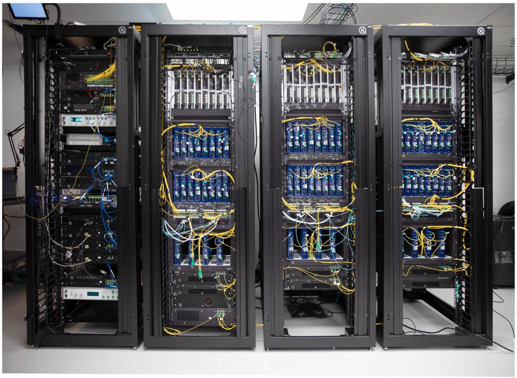
الشكل البياني الممتد 1|صورة لنظام أورورا. يتناسب النظام بالكامل، باستثناء مجموعة الكشف المبردة، في أربعة رفوف خادم قياسية بحجم 19 بوصة ويعمل بالكامل باستخدام جهاز كمبيوتر خادم واحد.
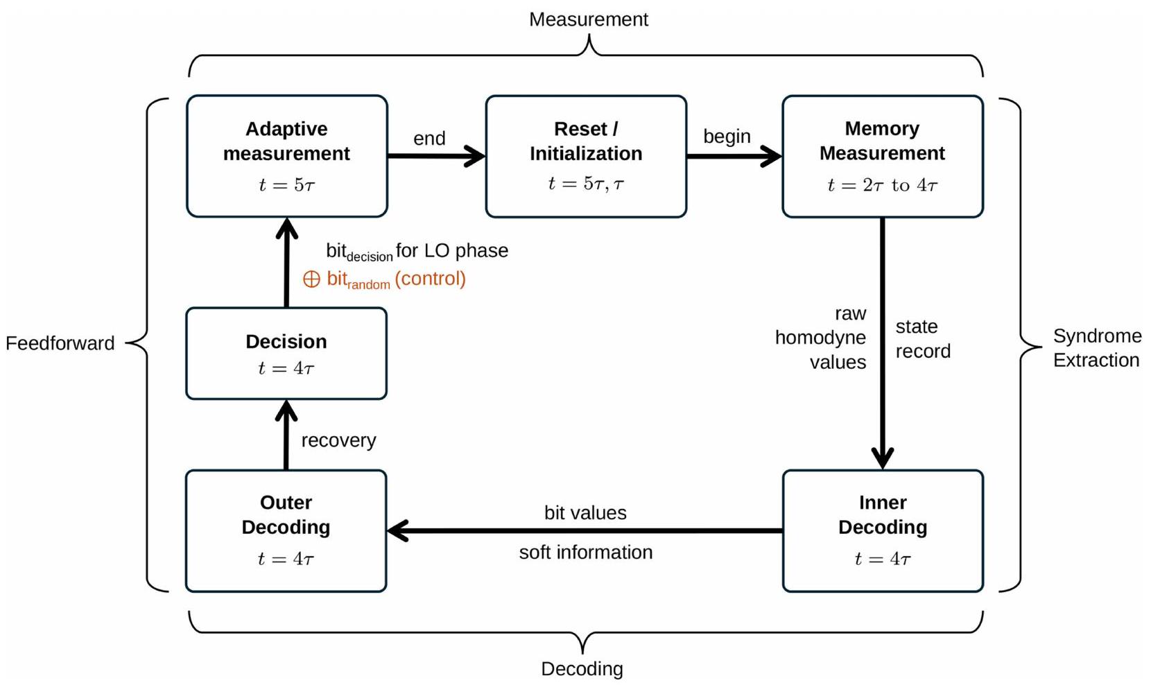
الشكل البياني الموسع 2 | ملخص للخطوات في عرض التكيف. تبدأ الدورة عند الكتلة الوسطى من خطوة القياس، عندما يتم تهيئة حالة العنقود. يتم إجراء قياسات مثبتات رمز التكرار والانتقالات في الخطوات الزمنية من 2 إلى 4. يعمل جهاز فك التشفير على البيانات المجمعة في هذه تقوم الخطوات الزمنية باتخاذ قرار بشأن القياس الذي سيتم تنفيذه في الخطوة الزمنية التالية. في التجربة الضابطة، يتم عشوائية هذا القرار. في الخطوة الزمنية الخامسة والأخيرة، يتم تعديل أساس القياس بناءً على هذا القرار.
Scaling and networking a modular photonic quantum computer
https://doi.org/10.1038/s41586-024-08406-9
Received: 25 June 2024
Accepted: 14 November 2024
Published online: 22 January 2025
Open access
Check for updates
H. Aghaee Rad , T. Ainsworth , R. N. Alexander , B. Altieri , M. F. Askarani , R. Baby , L. Banchi , B. Q. Baragiola , J. E. Bourassa , R. S. Chadwick , I. Charania , H. Chen , M. J. Collins , P. Contu¹, N. D’Arcy¹, G. Dauphinais¹, R. De Prins¹, D. Deschenes¹, I. Di Luch¹, S. Duque¹, P. Edke¹, S. E. Fayer , S. Ferracin , H. Ferretti , J. Gefaell , S. Glancy , C. González-Arciniegas , T. Grainge , Z. Han¹, J. Hastrup¹, L. G. Helt¹, T. Hillmann¹, J. Hundal¹, S. Izumi¹, T. Jaeken¹, M. Jonas¹, S. Kocsis¹, I. Krasnokutska¹, M. V. Larsen¹, P. Laskowski¹, F. Laudenbach¹, J. Lavoie , M. Li , E. Lomonte¹, C. E. Lopetegui¹, B. Luey¹, A. P. Lund , C. Ma , L. S. Madsen , D. H. Mahler , L. Mantilla Calderón , M. Menotti , F. M. Miatto , B. Morrison , P. J. Nadkarni , T. Nakamura , L. Neuhaus¹, Z. Niu¹, R. Noro¹, K. Papirov¹, A. Pesah¹, D. S. Phillips¹, W. N. Plick¹, T. Rogalsky¹, F. Rortais¹, J. Sabines-Chesterking¹, S. Safavi-Bayat¹, E. Sazhaev¹, M. Seymour¹, K. Rezaei Shad¹, M. Silverman , S. A. Srinivasan , M. Stephan , Q. Y. Tang , J. F. Tasker , Y. S. Teo , R. B. Then , J. E. Tremblay¹, I. Tzitrin¹, V. D. Vaidya¹, M. Vasmer¹, Z. Vernon¹, L. F. S. S. M. Villalobos¹, B. W. Walshe , R. Weil , X. Xin , X. Yan , Y. Yao , M. Zamani Abnili & Y. Zhang
Photonics offers a promising platform for quantum computing , owing to the availability of chip integration for mass-manufacturable modules, fibre optics for networking and room-temperature operation of most components. However, experimental demonstrations are needed of complete integrated systems comprising all basic functionalities for universal and fault-tolerant operation . Here we construct a (sub-performant) scale model of a quantum computer using 35 photonic chips to demonstrate its functionality and feasibility. This combines all the primitive components as discrete, scalable rack-deployed modules networked over fibre-optic interconnects, including 84 squeezers and 36 photon-number-resolving detectors furnishing 12 physical qubit modes at each clock cycle. We use this machine, which we name Aurora, to synthesize a cluster state entangled across separate chips with 86.4 billion modes, and demonstrate its capability of implementing the foliated distance-2 repetition code with real-time decoding. The key building blocks needed for universality and fault tolerance are demonstrated: heralded synthesis of single-temporal-mode non-Gaussian resource states, real-time multiplexing actuated on photon-number-resolving detection, spatiotemporal cluster-state formation with fibre buffers, and adaptive measurements implemented using chip-integrated homodyne detectors with real-time single-clock-cycle feedforward. We also present a detailed analysis of our architecture’s tolerances for optical loss, which is the dominant and most challenging hurdle to crossing the fault-tolerant threshold. This work lays out the path to cross the fault-tolerant threshold and scale photonic quantum computers to the point of addressing useful applications.
Over the past 5 years, there has been a sea change in the focus of quantum-computing development efforts. Although the hardware available across all platforms is still firmly rooted in the noisy intermediate-scale quantum era , far in both performance and scale from the point of accessing high-value applications such as factoring and quantum simulation of materials or chemistry , there has been waning interest in exploiting such noisy intermediate-scale quantum machines to extract utility in the near term. Instead, research has turned towards advancing the state of the hardware supporting error correction and fault tolerance . With recent resource estimates for promising
algorithms requiring millions of gates applied to hundreds of logical qubits , a tactical retreat is warranted from near-term application implementation, to enable deeper investment of resources towards advancing scalability and physical qubit-level error rates.
The challenge of physically realizing a quantum computer that can deliver meaningful results on a useful algorithm hinges on two closely related hurdles: achieving component performance sufficient to yield physical qubit error rates that are below the threshold for fault tolerance , and the ability to scale the system to large numbers of qubits. Scaling is crucial not only to provide sufficient qubits to
meet the demands of useful algorithms but also to accommodate the physical-to-logical qubit overhead (that is, encoding rate) required to suppress logical error rates to levels that are tolerable to the algorithm in question. The latter could be mitigated by using higher-rate quantum low-density parity-check (LDPC) codes , but remains a significant challenge. So far, none of the multiple strategies based on different physical substrates have overcome these hurdles, despite significant progress across many qubit modalities. Superconducting qubits have yielded demonstrations of computational advantage in random sampling problems , and it has been experimentally shown that error-correcting codes can be implemented in these machines to suppress error rates by increasing the code distance . Neutral atom- and ion-trap-based platforms have demonstrated logical gate implementation with convincing evidence of subthreshold operation. Within photonics-based platforms, machines have hosted sampling-based demonstrations of quantum computational advantage , although they suffer from high photon losses and other noise sources that make them vulnerable to classical simulation , as well as a wide array of programmable quantum information processing tasks . Here we design and demonstrate a complete photonic architecture that can, once appropriate component performance is achieved, deliver a universal and fault-tolerant quantum computer.
To achieve quantum computing, photonics platforms require the development of an architecture that comprehensively addresses all aspects of qubit synthesis, control and measurement in the context of fault-tolerant operation. Even notwithstanding performance, the existing demonstrations of photonic quantum computers , although groundbreaking in their own right, all lack key functional features that are required to furnish a universal machine capable of implementing qubit error correction and fault-tolerant gates. Implementations of single-photon-based dual-rail-encoded qubit architectures have so far failed to incorporate the multiplexing subsystems needed to overcome punishingly low success probabilities in qubit synthesis and non-deterministic gates, and lack the features necessary for real-time diagnosis and correction of error syndromes. Although the performance of individual photonic components is still too limited by optical loss to operate in the fault-tolerant regime, demonstrations of the functionality of these components and the platform and systems integration needed to scale them need not wait.
Alongside progress in component performance, it is critical to characterize the evolving requirements for achieving fault tolerance and translate these into a detailed mapping between the high-level functions of the architecture and the physical building blocks used to implement them. This enables optimization of configurations with respect to a performance model constrained by realistic hardware limitations, accelerating progress. In the process, it is essential to include advances in quantum error correction that relax the requirements for fault tol-erance-here we incorporate and report on decoder-based improvements to the quantum-error-correction threshold. Earlier examples of photonic architectures proposed laid out the abstract basic building blocks needed, namely, sources of few-photon resource states and spatiotemporal linear optical operations augmented by single-photon detectors for the ‘fusion-based’ approach , or sources of non-Gaussian states and spatiotemporal linear optical operations augmented by homodyne detectors for the optical Gottesman-Kitaev-Preskill (GKP) approach . Although promising progress on the performance and function of many building blocks for both approaches has been repor ted , no complete photonic architecture has been experimentally demonstrated in practice at any scale, leaving claims of modularity, networkability and scalability open to speculation.
The architecture presented here follows the optical GKP approach, which offers a distinct advantage in its ability to implement logic gates and error correction using deterministic, room-temperature linear optical operations and modest component depths for the various optical paths in the system. Entangling operations and logic gates are
deterministic, relying on beamsplitters and photodiodes (that is, only room-temperature components) to furnish the physical functions necessary; this is to be contrasted with the single-photon approach, which suffers from non-deterministic operation and requires (cryogenic) superconducting photon detectors not only for input state synthesis but also at almost every stage. In comparison, the optical GKP approach requires cryogenics only to herald certain input states at the qubit preparation stage.
The original continuous-variable measurement-based quantum computing model is similar to its qubit counterpart. Key features are that information is encoded in the quadrature basis and Gaussian unitaries and homodyne measurements have the role of Clifford gates and Pauli measurements. The model can be made fault tolerant while preserving these features by encoding qubits in each mode through the GKP code . Further details about fault tolerance and universality can be found in ref.5. By switching to resource states based on macronodes constructed from entangled pairs and Greenberger-Home-Zeilinger (GHZ)-type measurements, this model becomes easier to implement (only requires photon-number-preserving Gaussian unitaries) and has better performance .
Our architecture (including the Aurora system) is shown in Fig. 1, and consists of three stages. Gaussian boson sampling (GBS) devices prepare the heralded initial non-Gaussian states. Adaptive interferometer trees with homodyne detectors (which we refer to as ‘refineries’) improve the quality and probability of the non-Gaussian states and entangling them into two-mode GKP Bell pairs. This is followed by an array of quantum processing unit (QPU) cells that select the best-quality Bell pairs, entangle them into a spatiotemporal cluster state and implement gates by performing homodyne measurements on each mode; here we use the term ‘QPU’ to refer strictly to this subsystem and its constituent cells, not the entire quantum computer apparatus. Each of these three stages is implemented on distinct sets of photonic integrated circuit (PIC) chips, which are networked with phase- and polarization-stabilized fibre-optical interconnects.
Using GBS devices unassisted to directly produce GKP states has the drawback of low success probability , introducing excessive levels of loss and physical component overheads by requiring high-depth switch networks. This can be mitigated by searching the GBS circuit parameter space and using configurations found that furnish useful non-Gaussian states with higher probability. These states need not be GKP states themselves, provided they can be converted into GKP states at the refinery. In our architecture, as depicted in Fig. 1, the refinery contains two symmetric binary trees of adaptive beamsplitters, with all but one of the outputs of each tree being measured in the momentum quadrature basis by homodyne detectors.
Each unit cell of the binary tree can perform either a simple switch operation or one round of breeding , enabling any subset of the input states to be selected and bred, as the breeding steps can occur anywhere in the tree. This is equivalent to using an -inputs-to- -outputs multiplexer (MUX), followed by breeding of the outputs, but with a shallower optical path and thus less loss. The outputs of the trees are GKP states defined on rectangular lattices, specified by the photon-number outcomes. A measurement-based squeezer , using only elements already required (squeezed states provided on demand by select outputs of the GBS chips, an adaptive beamsplitter and a homodyne detector), is then used on each tree output to align them to a single GKP phase space lattice. The chosen lattice corresponds to the so-called square-grid quanaught state, which is periodic in both position and momentum quadratures . Finally, the outputs of two such trees are interfered on a 50:50 beamsplitter that entangles them to form a GKP Bell pair, which serves as the basic unit from which a cluster state can be synthesized.
The choice of cluster state and error-correction code used simply correspond to a choice of how the fibres carrying the Bell pairs are routed to the next array of QPU chips. Thus, implementing lattices
Fig. 1 | Layout of the architecture including loss paths and . Top: schematic of our architecture. Precursors to GKP states are generated from multimode Gaussian states produced probabilistically with GBS chips by heralding particular PNR patterns. Many precursor states are sent to each refinery chip (via optical fibre delays represented by blue lines), which use a combination of multiplexing and breeding implemented in a binary tree of beamsplitters (represented by the wedge-like shapes labelled ‘ B ‘), and squeezing, to create a pair of high-quality GKP sensor states. For the faulttolerant architecture, the binary tree is augmented with homodyne detectors. A Bell pair is then generated by applying a beamsplitter (black solid lines). The spatial routing and temporal delays of the modes in each pair are
set by the desired cluster-state graph, such that each graph macronode corresponds to an individual QPU chip and these chips share entangled pairs if they are neighbours on the cluster-state graph. In the fault-tolerant architecture, multiple pairs are created per edge, but only one pair is selected per graph edge by a multiplexer at the beginning of the QPU. Then, each QPU interferes with the selected pairs using static beamsplitters and these modes are measured using homodyne detection. Loss paths are shown with red dashed lines while classical feedforward is represented with black dashed lines. Middle: table showing the internal structure of each submodule in the fault-tolerant architecture and in the Aurora experiment. Bottom: legend for optical component diagrams.
with non-local connectivity is straightforward, making our architecture compatible with higher-rate LDPC codes . To ensure persistent entanglement between qubit sites at adjacent clock periods-required for measurement-based quantum computation-a subset of Bell pairs experiences a time delay on one of their modes using a fibre-optical delay line. Several GKP Bell pairs are generated per cluster-state lattice edge, with the two modes from each pair sent to QPU cells. Each of the QPU cells, which are arranged in arrays on another set of photonic chips, corresponds to a cluster-state lattice site, or macronode ; these sites in turn correspond to physical qubits available for computation. The first stage of the QPU chips provides a final layer of switching, where the best pair per lattice edge is selected for use by a small binary tree; this selection is made based on the homodyne detection outcomes in the refinery, and the photon-counting outcomes from the GBS cells. The selected Bell pairs are finally subjected, within each QPU cell, to phase shifters that implement GKP Hadamard gates, converting them into two-qubit cluster states, and then a short sequence of static beamsplitters and homodyne measurements that project these inputs onto GHZ states to create the desired fully connected cluster state . The measurement bases are selected on each clock cycle by a classical controller that is informed by both the user-defined algorithm and the error-correction protocol (including a decoder), taking into account
measurement outcomes from previous computational time steps. Full universality is achieved with magic states encoded in the GKP code and included into the pair creation or generated through measurements on the cluster state . Such magic-state generation is not expected to worsen the tolerance for losses in our architecture, but further work is needed to conclusively verify this.
Experiment
The architecture described relies on four key functionalities, all of which must be implemented in an integrated and indefinitely scalable platform to furnish a fault-tolerant quantum computer without inherent limitation in qubit number. These functionalities are: (1) heralded synthesis of non-Gaussian states using photon-number-resolving (PNR) detectors, (2) real-time feedforward actuation of binary trees of beamsplitters based on these detector events, (3) entanglement of the outputs of these trees to form a spatiotemporal cluster state, and (4) quadrature measurements implemented on all nodes of the cluster state at each clock period fed into a decoder implemented in real time, with single-clock-cycle feedforward available to inform subsequent measurement bases using prior measurement outcomes. To demonstrate the technological feasibility of this approach, we constructed a
Fig. 2|Schematic diagram of the Aurora system and main modules. An array of 24 sources chips generates squeezed states and entangled two-mode Gaussian states. These are pumped by a customized pulsed laser system (leftmost rack), which also generates and distributes local oscillator beams and reference beams for locking to the compute modules. PNR detectors are used on one half of each of the two-mode Gaussian state outputs from these chips (sources) to herald a non-Gaussian state; a stabilized fibre delay line buffers (fibre delays) the other mode while awaiting these detection results. The heralded outputs are fed into an array of six refinery chips (refinery), each of which is dynamically actuated to select the best-available pair of inputs using a pair of four-to-one binary tree multiplexers to synthesize an entangled Bell pair. Six such pairs are available after the refinery; one half of two pairs is delayed, through the routing modules (fibre delays), to generate entanglement
model of this architecture (shown in Fig. 1, using the components listed in the ‘Aurora’ row of the table) incorporating all of these functional features in a modular, indefinitely scalable platform. This machine hosts a sources subsystem with 84 squeezers within 42 GBS cells, distributed across an array of 21 (plus 3 extras for redundancy) silicon-nitride PICs, providing 12 squeezed states and 36 heralded non-Gaussian states using 36 PNR detectors. The outputs feed 48 inputs to a refinery array with 12 binary switch trees across 6 thin-film lithium-niobate multiplexer PICs, each yielding 1 entangled Bell pair. The modes comprising these pairs, after suitable temporal delay on a subset, are entangled into a cluster state and measured on each clock cycle by five QPU chips (through the method described in ref. 37), implemented on silicon PICs, which interface in real time with a classical decoder implemented on a field-programmable gate array. A schematic of the machine is presented in Fig. 2 and is described in full detail in Supplementary Information. The entire system fits into four standard server racks that house fully packaged modules operating at room temperature, with the sole exception of the PNR detection system, which is housed in a cryostat. All PIC modules are networked using custom phase- and polarization-stabilized fibre delay line modules to carry quantum light between stages and appropriately entangle modes on separate QPU chips to enable cluster-state synthesis.
between adjacent clock periods. All pairs are then stitched into a spatiotemporal cluster state by an array of 5 QPU chips, which also performs homodyne measurements on all 12 operating modes on every clock cycle. Equivalently, each QPU chip implements a multimode GHZ measurement, thereby generating a fully connected resource state. The fibre routing pattern between the refinery and the QPUs, illustrated by the yellow cabling at the bottom of the racks, implements the desired cluster-state lattice by appropriately networking the QPUs. For clarity, other fibre cabling paths, from the laser system to the compute system and from the sources modules to PNRs or down to the refinery inputs through delay lines, are not shown. Details of the full-system hardware blueprint, the laser system and modules can be found in Supplementary Figs. 22, 24 and 30-33, respectively.
To benchmark the key functionalities listed above, core experiments were carried out using the machine. First, the system was programmed to pass only squeezed states through to the QPU array (as opposed to the heralded non-Gaussian state outputs) and thus synthesize a -mode Gaussian cluster state, where is the duration of the experiment in clock periods. This benchmark tests all functional components of the system except feedforward features and PNR detection. The description of the resource state-prepared using the methods described in ref. 37 -can be simplified by back-evolving the measured modes through the QPU unitary (also known as expressing the state in terms of its distributed modes ), resulting in correlated pairs arranged as shown in Fig. 3a. Neighbouring macronodes are connected if the pair that links them is inseparable. The results (nullifier variances) are shown in Fig. 3b, plotted as a function of their temporal mode index. Continuously acquired over 2 hours, this result represents the synthesis and measurement of a macronode cluster state consisting of 86.4 billion modes, or billion temporal modes. Despite the high optical losses of about 14 dB from the synthesis of the squeezed states to their ultimate detection in the QPU, these variances are persistently below the vacuum noise level, indicating squeezing and validating the entanglement present in the cluster between both modes that form each pair. The degree of
Fig. 3| Synthesis and measurement of a macronode cluster state. a, Graph representation of the 12 -mode cluster state. For each time window , entangled pairs (coloured dots joined by a solid line) span neighbouring macronodes. Mode (macronode) labels are provided in the first (fifth) time step and is the experiment clock period. One homodyne measurement per macronode is programmable, the rest are measured in . For mode pairs and , one mode has been time delayed, allowing computation and entanglement to persist in time. and represent the position and momentum quadrature operator, respectively.b, Nullifier variances versus time. By applying the inverse linear transformation of the macronode beamsplitter network to the measured quadrature outcomes, we obtained the quadrature values corresponding to the six individual entangled pairs before mutual interference. The nullifiers of these states (solid lines) are of the form (left panel) and (right panel). Their variance is kept below the vacuum noise over a continuous acquisition of 2 h (corresponding to 86.4 billion modes, the product of 7.2 billion temporal modes over 12 spatial modes) at a clock rate of 1 MHz . The operators (left panel) and (right panel) are operators relating to the anti-squeezed directions of the two-mode squeezed state, and their variances are observed
(faint lines) to be above vacuum noise for the duration of the acquisition. c, Adaptive capability. The and labels in a specify a measurement basis for the programmable homodyne measurement in each macronode, corresponding to or either, respectively. This measurement pattern measures two four-body repetition code check operators (with support on the two dark grey diamonds in a). This measurement pattern is repeated and homodyne data are collected for the 12 modes in every fifth time step. Separate covariance matrices are constructed from data when mode is measured in (left) versus (right). Matrix rows and columns are labelled to reflect the numbering of modes in a. The single-mode variance on the diagonals was removed for better contrast, while the covariance values are plotted in shotnoise units (SNU), the units in which vacuum has a variance of 1 and .d, Control experiment. The difference between covariance matrices corresponding to the – and -measurement basis decoder decision shown in c (left, ‘with feedforward’), and from an otherwise identical experiment in which the basis measured is determined by random choice instead of from the decoder decision (right, ‘without feedforward’).
nullifier squeezing agrees well with numerical simulations of the machine.
To showcase the feedforward and non-Gaussian-state synthesis capabilities of our device, a repetition code error-detection experiment on low-quality GKP states was carried out. Heralded on detecting two photons in the GBS heralding mode, outputs of GBS cells are found in even-parity squeezed cat states that crudely approximate simple two-peaked GKP sensor states . On failure to observe two photons, a squeezed state is selected by the multiplexer, so that the resulting cluster-state modes are in a combination of squeezed states and squeezed cat states-the latter make up on average of the modes. These are sufficiently rare that our results do not depend on their inclusion; the results are nearly identical if only squeezed states are used. We initialize a computation that performs two (foliated) repetition code
checks (through the measurements in time steps in Fig. 3a). Outcomes are processed by the QPU decoder, which computes bit values and estimates of phase error probabilities associated with the qubits involved in the parity checks, which are in turn used in belief propagation decoding . The decoder outputs an updated distribution of error probabilities used to quantify confidence in the recovery. We apply a thresholding function to the confidence value to decide which basis to measure at the following time step-if the recovery was established with high (low) confidence, the macronode in time step 5 is measured in the basis. The thresholding function results in and being selected and of the time, respectively. The effect of the feedforward operation can be observed by comparing correlations present in the homodyne data from modes in the fifth time step between and selected cases (Fig. 3c). We measure on macronodes
Fig. 4 | Fault-tolerance threshold. a, Loss budget and multiplexing depth required for fault-tolerant operation. We analyse loss tolerance along the three paths and as a function of the combined depth of balanced trees of beamsplitters in refinery and QPU chips shown in Fig.1. For architecture configurations with a given combined depth, surfaces are plotted that have been fitted to the most extremal attainable and tolerance values. Thus, each point on a given surface represents a combination of loss budgets assuming fixed total depth for the three principal optical paths in the system to meet the requirements for fault tolerance. The two yellow dots correspond
to a pair of example configurations with combined refinery and QPU depths of 15.b, Weighted loss threshold and depth. Changing the depth affects the distance of the surfaces in a from the origin. For each depth, we plot the weighted loss threshold, defined to be the average length component of all surface data points in the direction of an approximate normal vector . The vector is found by first constructing normal vectors for the planes specified by the three extremal ‘corner’ points of each surface, and then taking the average. Analysis of the architecture configurations with two-mode GBSs is presented in the Supplementary Information. and restrict two of the dumbbells, modes and modes in Fig. 3a, to always be Gaussian states so that the quadrature data have a simpler and more distinct structure. If the measurement readout and decoding could not be completed in time for the fifth step in the protocol, then the basis would not be chosen correctly with odds better than approximately random. We can simulate this in our set-up by repeating the protocol with the basis in the fifth time step chosen by a binary random variable uncorrelated with the decoding decision. If homodyne correlations were again plotted based on the decoding decision, this time they should appear identical. We plot the difference between the decoder-outcome-determined covariance matrices for the feedforward and no-feedforward scenarios in Fig. 3d.
Loss requirements
Returning to the full architecture proposed, we note that fault tolerance in any photonic architecture is highly dependent on photon loss, which is present in all optical submodules and components in Fig. 1. It is noted that sequential loss channels can be combined (transmissivity decays multiplicatively) and uniform loss along multiple paths commutes with linear optical transformations. Thus, the loss contributions can be converted into a single-mode channel acting on all modes independently, and this can be commuted to act before photon-counting or homodyne detectors, or any other chosen point in the path. We define three primary optical paths: , from squeezer to photon counter, , from squeezer to the homodyne in the refinery, and from the output of the MUX and breeding tree in the refinery to immediately before the homodyne detectors in the QPU. This way, the loss of the longest path can be computed by combining and
losses (assuming that the detector losses in the refinery are equal to those in the QPU). We also define the minor loss path , for the mode used in measurement-based squeezing. These loss paths are shown in Fig. 1. Commuting the relevant losses appropriately, their effects can be captured fully by figures of merit associated with the GKP Bell pair units that comprise the basic units of the architecture. The quality of approximate GKP qubits can be quantified by how well they act as physical qubits for the next layer of quantum error correction. We do this by relating the symmetric effective squeezing (see Supplementary Information for a description) to the squeezing requirements for fault tolerance of the surface code concatenated with the GKP code .
We perform a comprehensive optimization of different candidate ‘state factories’-the collections of elements that provide the best-available GKP Bell pairs to be entangled into a cluster state-and present the results in Fig. 4, in which the fault-tolerance threshold is visualized in relation to the loss present in the three principal optical paths in the architecture. The details of this optimization are presented in Methods. For ease of visualization, is not represented. However, incorporates a small subset of the elements experienced in , and its loss requirements are less stringent than any of ; thus if the loss bounds shown for those paths are achievable, so too must be the loss bound for . Each plane represents a fixed total depth (refinery tree depth plus QPU tree depth), and separates the region (in loss parameter space) compatible with fault-tolerant operation, closer to the origin, from that of above threshold operation. This puts clear lower bounds, for the architecture considered, on how much loss can be tolerated in the components comprising each optical path, given a constraint (dictated by engineering and cost requirements) placed on the number of GBS cells and maximum allowable refinery chip inputs
per physical qubit. In turn, this provides benchmarks against which hardware choices-such as around waveguide materials, chip-fibre coupling schemes and component designs-can be qualified.
Discussion and outlook
Although demonstrations of systems like Aurora help build confidence in the scalability of the photonic approach to quantum computing, there remains a gap-as with all hardware approaches-between present-day performance and the demands of fault tolerance. Although refinements are necessary to carry the modules responsible for qubit synthesis and processing from prototypes to mass manufacturing, our results indicate that the present-day technological backdrop of photonic-chip fabrication, classical control electronics and fibre-optical networking make feasible the task of modularizing and scaling a realistic photonic architecture for fault-tolerant quantum computing. In addition, the quantum optical theoretical underpinnings are now sufficiently well developed to enable thorough optimization of optical GKP-based architectures to find those that are most hardware efficient and tolerant to physical imperfections.
The component performance gap, however, is significant: whereas the currently known optimal configurations demand about loss budgets and challenging about 10 multiplexing depths to achieve fault-tolerant operation, Aurora shows losses of about for the heralding paths ( ), and slightly over for the heralded optical paths ( and ). Indeed, this system was constructed to demonstrate the scalability of the approach through modularity and networking. Although extensive design iterations and post-fabrication selection were performed, no special loss optimizations were carried out on the chip platforms employed, which were all based on pre-existing commercially available fabrication lines.
The loss tolerances in Fig. 4 are not hard upper bounds but rather are attainable lower bounds by explicit circuits; here we limited ourselves to a structured analytically derived family of GBS sources, adaptive cat-state breeding as the refinery protocol and a particular method for constructing cluster states. The loss tolerance of paths , and can be increased and circuit depths of refinery and QPU chips can be decreased by further optimization of theoretical protocols, although we expect these loss tolerances to remain within one order of magnitude of currently contemplated ranges. This may be accomplished, for example, by using alternative GBS circuits, more advanced refinery protocols, alternative cluster-state-generation protocols, noise-tailored quantum-error-correcting codes along with noise-biased or non-square lattice GKP codes , and closer-to-optimal decoders, all of which are deserving of future attention and may modify the loss tolerances of different paths by multiple percentage points.
Closing the gap between the present state of the art in hardware components and that required for fault tolerance is expected to require contribution from both architectural refinements and hardware improvements. Towards the latter, intensive efforts are underway in customized fabrication process engineering and photonic and fibre component design to achieve the loss budgets required. We summarize our latest component-level results towards this goal for each relevant subsystem in Methods. Taken in aggregate, an improvement of 20-30 times (when measured on a decibel scale) in each photonic component insertion loss compared with this current state of the art would enable fault-tolerant operation even if no further progress is made in relaxing architectural requirements. Recent reports of platform development for comparable components have also shown promising progress in loss reduction.
Beyond merely achieving component performance compatible with fault tolerance, manufacturing methods must be developed to ensure that these performance levels can be maintained in the context of mass production. For example, a depth-12 machine (that is, one with 8-times improved state factory overhead versus that considered in Fig. 4)
with 100 logical qubits and a 100-to-1 error-correction overhead would require tens of millions of GBS cells. Even assuming a 100 -times improvement in state-factory component density, this will necessitate tens of thousands of server racks in the state factory; if not all of these assumed improvements are possible, even more may be required. Although this is well within the scale of present-day classical data centres, progress in quantum photonic component performance must be guided by constraints that respect these requirements for large-scale manufacturing.
Online content
Any methods, additional references, Nature Portfolio reporting summaries, source data, extended data, supplementary information, acknowledgements, peer review information; details of author contributions and competing interests; and statements of data and code availability are available at https://doi.org/10.1038/s41586-024-08406-9.
Bravyi, S. et al. High-threshold and low-overhead fault-tolerant quantum memory. Nature 627, 778-782 (2024).
Paetznick, A. et al. Demonstration of logical qubits and repeated error correction with better-than-physical error rates. Preprint at https://arxiv.org/abs/2404.02280 (2024).
Google Quantum AI. Suppressing quantum errors by scaling a surface code logical qubit. Nature 614, 676-681 (2023).
Bluvstein, D. et al. Logical quantum processor based on reconfigurable atom arrays. Nature 626, 58-65 (2024).
Bourassa, J. E. et al. Blueprint for a scalable photonic fault-tolerant quantum computer. Quantum 5, 392 (2021).
Zhang, Y. et al. Squeezed light from a nanophotonic molecule. Nat. Commun. 12, 2233 (2021).
Menicucci, N. C. Temporal-mode continuous-variable cluster states using linear optics. Phys. Rev. A 83, 062314 (2011).
Preskill, J. Quantum computing in the NISQ era and beyond. Quantum 2, 79 (2018).
Shor, P. W. Algorithms for quantum computation: discrete logarithms and factoring. In Proc. 35th Annual Symposium On Foundations of Computer Science 124-134 (IEEE, 1994).
Alexeev, Y. et al. Quantum-centric supercomputing for materials science: a perspective on challenges and future directions. Future Gener. Comput. Syst. 160, 666-710 (2024).
McArdle, S., Endo, S., Aspuru-Guzik, A., Benjamin, S. C. & Yuan, X. Quantum computational chemistry. Rev. Mod. Phys 92, 015003 (2020).
Gidney, C. & Ekerå, M. How to factor 2048 bit RSA integers in 8 hours using 20 million noisy qubits. Quantum 5, 433 (2021).
Dalzell, A. M. et al. Quantum algorithms: a survey of applications and end-to-end complexities. Preprint at https://arxiv.org/abs/2310.03011 (2023).
Aharonov, D. & Ben-Or, M. Fault-tolerant quantum computation with constant error. In Proc. 29th Annual ACM Symposium on Theory of Computing 176-188 (ACM, 1997).
Kitaev, A. Y. Quantum computations: algorithms and error correction. Russ. Math. Surv. 52, 1191 (1997).
Knill, E., Laflamme, R. & Zurek, W. H. Resilient quantum computation. Science 279, 342-345 (1998).
Breuckmann, N. P. & Eberhardt, J. N. Quantum low-density parity-check codes. PRX Quantum 2, 040101 (2021).
Arute, F. et al. Quantum supremacy using a programmable superconducting processor. Nature 574, 505-510 (2019).
Wu, Y. et al. Strong quantum computational advantage using a superconducting quantum processor. Phys. Rev. Lett. 127, 180501 (2021).
Moses, S. A. et al. A race-track trapped-ion quantum processor. Phys. Rev. X 13, 041052 (2023).
Egan, L. et al. Fault-tolerant control of an error-corrected qubit. Nature 598, 281-286 (2021).
Madsen, L. S. et al. Quantum computational advantage with a programmable photonic processor. Nature 606, 75-81(2022).
Zhong, H.-S. et al. Quantum computational advantage using photons. Science 370, 1460-1463 (2020).
Oh, C., Liu, M., Alexeev, Y., Fefferman, B. & Jiang, L. Classical algorithm for simulating experimental Gaussian boson sampling. Nat. Phys. 20, 1461-1468 (2024).
Arrazola, J. M. et al. Quantum circuits with many photons on a programmable nanophotonic chip. Nature 591, 54-60 (2021).
Alexander, K. et al. A manufacturable platform for photonic quantum computing. Preprint at https://arxiv.org/abs/2404.17570 (2024).
Bartolucci, S. et al. Fusion-based quantum computation. Nat. Commun. 14, 912 (2023).
Gottesman, D., Kitaev, A. & Preskill, J. Encoding a qubit in an oscillator. Phys. Rev. A 64, 012310 (2001).
Larsen, M. V., Chamberland, C., Noh, K., Neergaard-Nielsen, J. S. & Andersen, U. L. Faulttolerant continuous-variable measurement-based quantum computation architecture. PRX Quantum 2, 030325 (2021).
Fukui, K., Asavanant, W. & Furusawa, A. Temporal-mode continuous-variable threedimensional cluster state for topologically protected measurement-based quantum computation. Phys. Rev. A 102, 032614 (2020).
Asavanant, W. et al. Time-domain-multiplexed measurement-based quantum operations with 25-MHz clock frequency. Phys. Rev. Appl. 16, 034005 (2021).
Larsen, M. V., Guo, X., Breum, C. R., Neergaard-Nielsen, J. S. & Andersen, U. L. Deterministic multi-mode gates on a scalable photonic quantum computing platform. Nat. Phys. 17, 1018-1023 (2021).
Konno, S. et al. Logical states for fault-tolerant quantum computation with propagating light. Science 383, 289-293 (2024).
Menicucci, N. C. et al. Universal quantum computation with continuous-variable cluster states. Phys. Rev. Lett. 97, 110501 (2006).
Menicucci, N. C. Fault-tolerant measurement-based quantum computing with continuousvariable cluster states. Phys. Rev. Lett. 112, 120504 (2014).
Walshe, B. W. et al. Linear-optical quantum computation with arbitrary error-correcting codes. Preprint at https://arxiv.org/abs/2408.04126 (2024).
Tzitrin, I., Bourassa, J. E., Menicucci, N. C. & Sabapathy, K. K. Progress towards practical qubit computation using approximate Gottesman-Kitaev-Preskill codes. Phys. Rev. A https://doi.org/10.1103/PhysRevA.101.032315 (2020).
Fukui, K. et al. Efficient backcasting search for optical quantum state synthesis. Phys. Rev. Lett. 128, 240503 (2022).
Weigand, D. J. & Terhal, B. M. Generating grid states from Schrödinger-cat states without postselection. Phys. Rev. A 97, 022341 (2018).
Filip, R., Marek, P. & Andersen, U. L. Measurement-induced continuous-variable quantum interactions. Phys. Rev. A 71, 042308 (2005).
Duivenvoorden, K., Terhal, B. M. & Weigand, D. Single-mode displacement sensor. Phys. Rev. A 95, 012305 (2017).
Walshe, B. W., Baragiola, B. Q., Alexander, R. N. & Menicucci, N. C. Continuous-variable gate teleportation and bosonic-code error correction. Phys. Rev. A 102, 062411 (2020).
Walshe, B. W., Alexander, R. N., Menicucci, N. C. & Baragiola, B. Q. Streamlined quantum computing with macronode cluster states. Phys. Rev. A 104, 062427 (2021).
Richardson, T. & Urbanke, R. Modern Coding Theory (Cambridge Univ. Press, 2008).
Marek, P. Ground state nature and nonlinear squeezing of Gottesman-Kitaev-Preskill states. Phys. Rev. Lett. 132, 210601 (2024).
Publisher’s note Springer Nature remains neutral with regard to jurisdictional claims in published maps and institutional affiliations.
Open Access This article is licensed under a Creative Commons Attribution-NonCommercial-NoDerivatives 4.0 International License, which permits any non-commercial use, sharing, distribution and reproduction in any medium or format, as long as you give appropriate credit to the original author(s) and the source, provide a link to the Creative Commons licence, and indicate if you modified the licensed material. You do not have permission under this licence to share adapted material derived from this article or parts of it. The images or other third party material in this article are included in the article’s Creative Commons licence, unless indicated otherwise in a credit line to the material. If material is not included in the article’s Creative Commons licence and your intended use is not permitted by statutory regulation or exceeds the permitted use, you will need to obtain permission directly from the copyright holder. To view a copy of this licence, visit http://creativecommons.org/licenses/by-nc-nd/4.0/.
(c) The Author(s) 2025
Methods
The Aurora hardware system (Extended Data Fig. 1) is composed of six distinct principal subsystems: (1) a customized master laser system provides coherent pump and local oscillator beams, as well as reference beams for phase stabilization; (2) a sources array generates squeezed light and two-mode Gaussian states; (3) a PNR detection system is used for heralding non-Gaussian states; (4) an array of refineries, each multiplexing eight inputs to one entangled pair; (5) a QPU array forms the spatial and temporal connections in the cluster state and performs homodyne measurements on each qubit; and (6) an array of fibre buffers provides appropriate phase- and polarization-stabilized delay lines between the sources and refineries, as well as between the refineries and QPUs. The entire system, apart from the cryogenic detection array, fits into 4 standard 19-inch server racks. Here we summarize the main features of these subsystems, as well as our method for verifying the multimode entanglement present in our cluster-state benchmark experiment; a more detailed exposition of these topics is available in Supplementary Information.
Laser system
The laser system is responsible for providing appropriate pump pulses (P1 and P2) to each squeezer in the sources array, a local oscillator beam temporally mode-matched to the quantum pulses for homodyne detection, and a variety of reference beams used to stabilize fibre delays (ref) and resonator positions (probe) throughout the rest of the system.
The laser system (depicted in Supplementary Fig. 24) begins with five narrow-linewidth lasers (P1, P2, local oscillator, ref and probe), all manufactured by OEWaves (OE4040-XLN) except for the probe, which was made by PurePhotonics (PPCL550). A broadband electro-optic frequency comb is derived from the local oscillator laser and serves as a frequency/phase reference to stabilize the remaining four lasers. Each laser is then modulated at the experimental clock rate of 1 MHz to provide temporal modes suitable to their purposes: the pumplasers are carved into 1-ns pulses (Exail MXER-LN-20, DR-VE-10-MO), the ref and probe lasers are carved into 400 ns (with AO Fiber pigtailed Pulse Picker from AA Opto-Electronic) and 50-ns pulses (using Exail MXER-LN-20), respectively, interleaved with the pump pulses at a later stage. The local oscillator laser has its complex temporal envelope mode-matched (using Exail MXIQER-LN-30) to the output of a representative squeezer (selection process is described in Supplementary Information). Each pulse train is amplified to a suitable power using erbium-doped fibre amplifiers (Model Pritel MC-PM-LNFA-20) before being combined into a polarization-maintaining fibre (with Opneti PMDWDM-1-1-CXX-900-5-0.3-FA). P1, P2 and local oscillator beams again have their phases stabilized, before being distributed among two sets of channels. The first channel, of which there are 24 copies, contains P1, P2, probe and ref, and is sent onwards to the sources array. The second channel, of which there are five copies, contains the local oscillator and ref, and is sent onwards to the QPU for coherent detection. Owing to the manner in which the beams are distributed, the ref laser carries the phase information in the system and thus can be used to stabilize measurement angles in the QPU. A second copy of the ref beam, slightly detuned in frequency, is sent on to the refinery array and used to stabilize interconnections between sources and refinery as well as between refinery and QPU.
Sources array
Each of the 24 sources chips are identical in design, and are based on the silicon-nitride waveguide platform provided by Ligentec SA and fabricated on their production manufacturing line at X-Fab Silicon Foundries SE. Squeezers in these devices are based on a photonic molecule design, in which a pair of microring resonators are tuned to enable degenerate squeezed light to be generated using a dual-pump scheme, while leading-order unwanted parasitic nonlinear processes are suppressed . The generated squeezed states are characterized
using optical heterodyne tomography and found to be nearly single mode. The local oscillator temporal mode is matched to the dominant temporal mode as described in Supplementary Information. The outputs of the squeezers are passed through integrated asymmetric Mach-Zehnder interferometer (MZI) filters to remove pumplight, then entangled by a tunable linear optical interferometer. Tuning of the interferometer, filters and resonators is accomplished using thermo-optic phase shifters. The chips are in size, and are fully packaged and encased in a modular enclosure that mounts on a custom backplane chassis assembly. The end-to-end insertion loss (from pump input to quantum output) of the chips is 2.16 dB , and 1.82 dB of loss is experienced by the quantum light from when it is generated to when it is available in the fibre outputs. This figure includes an estimated squeezer resonator escape efficiency of ( )%, filter and interferometer propagation loss of , and chip out-coupling loss of coupling efficiency .
Newer designs based on different fabrication platforms and components, although not yet deployed in Aurora, have since been developed that combine multiple layers of thin silicon-nitride waveguides with a dispersion-optimized thicker layer, enabling much lower chip-fibre coupling loss, and higher squeezing through better suppression of parasitic nonlinear processes. Single-mode waveguide propagation losses of approximately have been demonstrated, with even lower losses available in wider cross-sections for resonators. Escape efficiencies in squeezer microresonator structures exceeding 98% are routine, but further improvements in design and fabrication are needed to maintain an acceptable loaded quality factor under such strong over-coupling conditions. Similarly, chip-fibre coupling from these devices with losses of approximately 0.1 dB have been observed, with simulations for future structures indicating that arbitrarily low losses are possible. These results are consistent with recent progress reports in low-loss quantum photonic component development . Even once realized, maintaining such low chip-fibre coupling losses through the packaging process in a manufacturing line capable of producing the millions of chips needed to furnish machines of practical utility remains an outstanding challenge.
PNR detection system
The PNR detection system is based on an array of 36 transition edge sensors (TES), housed in a pair of Bluefors (LD400) dilution refrigerators at base temperature. These sensors are inductively coupled to an array of coherent superconducting quantum interference devices (SQUID) for cryogenic amplification, the signals from which are digitized and analysed in real time by an array of field-programmable gate array boards that discriminate photon number from the analogue pulses emerging from each sensor. Previously, such TES detectors were limited to repetition rates of a few hundred kilohertz, owing to their intrinsic thermal reset behaviour; higher experimental repetition rates required the use of demultiplexers , which are undesirable owing to their added loss and complexity. The TES detectors employed in Aurora enjoy native operation at 1-MHz repetition rate, while preserving photon miscategorization error below for photon numbers up to 7. To enable this, the sensors were fabricated with small gold fins deposited at the margins of the tungsten absorber area; this engineers the thermal response of the detectors to absorbed photons to become faster by increasing the electron-phonon coupling with minimal impact on the other performance metrics of the detectors. The detection efficiency of this generation of TES detectors was not optimized for Aurora, and ranged from to .
The majority of the spread in this detection efficiency is believed to originate from variations in the detector packaging process. In Aurora, the deployed sensors were assembled by hand with no special quality assurance process enforced. More recently, TES detectors with operational speed at or above 1 MHz have been measured with consistently high detection efficiency above . This is expected to increase to
at least 97%, matching the best channels available in Aurora, as a more reliable packaging and assembly process is developed. Still, PNR detection efficiencies over 99% are needed to stay within the loss budgets for the path in our architecture (Fig. 1). Our simulations indicate that the primary challenge to achieving this, apart from repeatable and reliable assembly processes, lies in obtaining tight process control over the multilayer dielectric stack parameters used to form the optical cavity that enhances photon absorption in the tungsten film.
Refinery array
The refinery array consists of 6 nominally identical PICs, in size, based on the thin-film lithium-niobate PIC platform offered by HyperLight and fabricated on a semiconductor volume manufacturing line. Two binary trees-each composed of three electro-optic MachZehnder modulator switches-select, based on feedforward instructions provided by the PNR detection system, the switch pattern that optimizes the output state. These MZI switches have an average insertion loss of 0.19 dB , giving an average total insertion loss of 4.15 dB for the full optical path through each refinery chip, which includes the binary tree, chip in- and out-coupling, and Bell pair entangling beamsplitter losses. Pairs of refinery chips, all of which are fully packaged, are hosted in three rack-mounted enclosures. Appropriate duty cycling of the switch settings between quantum pulse time windows allows the voltage bias of each modulator to be continually monitored and locked, yielding an average switch extinction ratio of more than 30 dB .
In Aurora, the refinery chips implement probability-boosting multiplexing as well as Bell pair synthesis, but do not have homodyne detectors at the multiplexer switch outputs and thus do not implement breeding. Efforts are underway to integrate photodiodes into the refinery chip platform, and we expect the next generation of refineries to implement the full adaptive breeding protocol.
Although the modulation and detection bandwidths demanded by the refinery’s functions are not especially challenging compared with other applications, the loss requirements are. The importance of lower losses in MZI switches is compounded by the number of them present in the various optical paths. In the versions of the architecture contemplated in Fig. 4, the deepest combined path ( and in Fig. 1) incorporates as many as 15 MZI switches. Even neglecting all other losses, this would mean that no more than approximately 7 mdB can be tolerated in each switch. Efforts to obtain this are well underway, with recent design and process optimizations yielding performance consistent with losses of 30 mdB per MZI switch. Early indications point to the importance of optimizing the thin-film lithium niobate (TFLN) etching process to manage scattering losses in the underlying waveguides. In addition, electrical control approaches must be engineered that enable high driving voltages. The MZI switch loss is nearly proportional to its length; shorter modulator sections are perfectly acceptable optically, but require proportionately higher applied voltages to operate. The driving approach must be scalable to allow operation of thousands of adaptive switches on the same chip. High-voltage-compatible integrated circuit fabrication nodes are being explored for this purpose. Other approaches using alternative materials such as barium titanate have shown promise for delivering lower-voltage operation in this context, but further process improvements would be needed to compete with TFLN on raw propagation loss.
QPU array
The QPU array consists of 5 nominally identical modules, each based on a silicon photonic-chip platform offered by AIM Photonics that hosts silicon-nitride and silicon waveguides, germanium photodiodes, and carrier depletion modulators. Within the chips, each measuring and fully packaged within a rack-mounted enclosure, silicon nitride is used for edge coupling from the fibre inputs and for the interferometer that implements spatial entanglement in the cluster state. The quantum light then transitions to silicon waveguides and is
mixed with local oscillator light on appropriate beamsplitters, and terminates on germanium photodiodes for homodyne detection. The loss experienced by each quantum input to the QPU is on average 3.68 dB , of which 0.82 dB arises from the edge couplers and optical packaging, 2 dB from the interferometer circuit and 0.86 dB from the photodiodes. The local oscillator input to one homodyne detector is modulated using silicon carrier injection modulators, with each quadrature phase setting actuated based on real-time instructions from the digital QPU controller. This controller is based on a field-programmable gate array, which is programmed to select the appropriate measurement bases, taking into account the algorithm and decoder protocol selected by the user.
The full signal chain latency from an optical pulse arriving at the homodyne detectors to the actuation of an updated local oscillator phase is approximately 976 ns . Out of this, 240 ns is spent on converting the optical homodyne pulse to a normalized 16-bit fixed-point number, involving photodiode response, transimpedance amplification, analogue-to-digital conversion, and digital signal processing for pulse integration and normalization. Another 672 ns is the worst-case serial link latency spent on serialization, propagation to the QPU backend, de-serialization of the 16-bit number, plus serialization, propagation back to each of the 5 QPUs, and de-serialization of the 2-bit local oscillator phase selection command. The remaining 64 ns are used for the decoder algorithm to calculate the next local oscillator phase setting from measurement information of all homodyne detectors from previous clock cycles. Future decoders requiring more digital clock cycles to carry out intervening computations could be deployed on digital circuits with higher clock speeds, or the increased latency could be offset by latency improvements in other parts of the signal chain. For example, latency could be improved by selecting lower-latency analogue-to-digital converters for digitizing the homodyne measurements, by optimizing the signal processing chain for homodyne value normalization, and by improving the serialization and de-serialization latencies associated with the serial links by means of using field-programmable gate arrays with high-speed ( ) serial input/output pins for the QPUs.
The full fault-tolerant design, involving refineries that incorporate breeding, would have identical chip platform requirements for the refinery as for the QPU, those being electro-optic modulators and photodiodes. In the future, we thus expect both the refinery and the QPU to be based on the same PIC platform, which will look closer to the TFLN-based substrate used for the refinery in this work.
Our recent work optimizing the design of integrated photodiodes has yielded quantum efficiencies as high as in the same germanium platform as that used in Aurora; the heterogeneous integration of high-quantum-efficiency photodiodes like these into TFLN devices is the last platform integration step required to equip Aurora with refineries capable of implementing breeding protocols. Considering this co-integration requirement with TFLN, our focus has turned towards using III-V-semiconductor-based photodiodes in place of germanium. Simulations indicate that evanescent coupling between TFLN waveguides and InGaAs photodiodes, appropriately fabricated, can deliver homodyne detectors with net quantum efficiency well above . The most challenging aspect of achieving this lies in the details of the heterogeneous integration scheme used. High-quality surface preparations within deep trenches will be needed at the interface between the photodiodes and the waveguide cladding. Managing excessive dark current in the photodiodes themselves as their dimensions grow to accommodate near-unity absorption will also require innovative approaches.
Interconnects
Between the sources and refinery modules, and between the refinery and QPU modules, interconnects are required that can provide a specified and fixed delay on the quantum pulses conveyed. For the sources-to-refinery links, the delay serves as a buffer for awaiting heralding information from the PNR detectors, whereas the refinery-to-QPU links implement
a delay of exactly one clock period on half of two different Bell pairs, enabling temporal entanglement in the cluster. The purposes of these delays differ slightly but they are otherwise identical in requirements. In particular, both must actively stabilize the link against fluctuating phase and polarization. This is accomplished by interleaving coherent classical reference pulses between each quantum pulse, interfering reference pulses between appropriate inputs to each chip, and feeding back on phase and polarization actuators in the fibre delay modules.
The delay lines themselves are implemented in discrete enclosed modules within the racks, and are each composed of a fibre coil of (about ). It is noted that the fibre coils in 10 out of the 12 channels between refinery and QPU are long (about ) such that the difference between the two interfering channel is exactly . Each fibre coil is in thermal contact with a thermo-electric cooler, which provides slow phase tuning with a large capture range, compensating for phase drifts that arise from the unstable global temperature environment in the racks. These are accompanied by piezoelectric fibre phase shifters (Luna FPS-001) that provide fast phase control over a smaller range, locking against acoustic fluctuations. An electrical polarization controller (Luna MPC-3X) within each fibre module is used to ensure the inputs to each chip are aligned to the appropriate waveguide mode.
These custom first-generation modules were manufactured by Luna Innovations, and have an average loss of ( ) dB, excluding connectors, while adding between and of phase noise (root mean square), when in closed loop operation.
Recent prototype designs have demonstrated losses of , of which 0.037 dB arises simply from the length of fibre itself in the delay. Future generations of this module are expected to be limited by only the fundamental propagation loss in the underlying fibre, which can be as low as in existing, commercially available products. Our initial studies have shown that the vast majority of the loss present in typical fibre delays arise from fibre connectors or splices between different constituent components. These are straightforward to eliminate by manufacturing fibre delay modules from a single draw of fibre. Thus, even without increasing the quantum clock speed beyond 1 MHz , using ultralow loss fibre and implementing these manufacturing changes is expected to achieve about 0.03 dB ( loss). Going beyond this would require faster clock speeds or lower loss fibre. In addition, the inherent modularity of the architecture allows for all the fibre interconnections to be spliced, or indeed discrete fibre components in a given off-chip path to be assembled from a single draw of fibre.
Entanglement verification
To verify the generation of multimode entanglement, we investigate the nullifier variance of the six Bell pair input states when the refineries are set to deterministically output squeezed states (that is, each pair is an approximate two-mode squeezed state). As we are interested in both and correlations, we alternate the cluster-state acquisition between the two measurement bases, measuring all modes in and , subsequently. Experimentally, the measurement basis was changed by a simultaneous phase rotation of all input modes using a setpoint change at our arbitrary-phase locks. For each basis, the data are acquired continuously over 2 hours, amounting to an uninterrupted measurement of 7.2 billion time bins (yielding 86.4 billion modes in total, combining all 12 operating modes at each time step). For the statistical analysis described below, the acquired data are processed in batches of 10 million time bins.
In the analysis, we obtain the statistical moments of the individual Bell pair states by ‘reverting’ the cluster-state stitch at the QPU (also known as synthesis of the macronode ). As a first step, we build the quadrature covariance matrix of all measurement outcomes. The elements of the covariance matrix are given by , where a subscript represents a spatiotemporal mode and the operator denotes the expected value (mean) of its argument. Our covariance matrix is of
dimension as we aim to capture not only the correlations among the 12 spatial modes but also their correlations to the quadratures of the subsequent time bin ( 12 modes for time bin plus 12 modes for time bin ). For this demonstration, we either measure all modes in or all modes in , so we can build only the position-position or momentummomentum subblocks of the full covariance matrix, which is sufficient for evaluation of Einstein-Podolsky-Rosen (EPR)-state nullifiers.
As part of the macronode synthesis, the six input Bell pair states are stitched together by a beamsplitter network, represented by the symplectic transformation . In our second analysis step, we apply the inverse of that symplectic to our quadrature covariance matrix to obtain the covariance matrix before the macronode stitch: . This back-transformed covariance matrix now represents six separable EPR states. Their nullifiers are defined as and . The variance of these nullifiers is obtained using the definition , where all variance and covariance terms are obtained from the elements of . To obtain the shot-noise reference for our EPR nullifiers, we apply the same operation to the vacuum data, obtained with all squeezed-light sources turned off.
It is noted that our method to evaluate the EPR nullifiers by applying the inverse macronode symplectic to the output covariance matrix is mathematically equivalent to applying to the nullifier equations and and evaluating the resulting equations using directly.
Adaptivity demonstration
In the adaptivity demonstration, we created the set-up for a distance-2 repetition code implemented through a cluster state composed of low-quality GKP states and squeezed states. Although the system is too noisy to show error suppression, we nevertheless demonstrate all the building blocks, collecting and processing of measurement data, running a decoder in real time, and performing a conditional operation at the following time step based on the recovery. The demonstration can be broken down into the following steps (Extended Data Fig. 2), with additional detail supplied in Supplementary Information section VIID:
Initialization. In time step , homodyne measurements decouple qubits , and measurements on all modes) and teleport quits , and ( measurements on modes 3 and 10, and elsewhere) to initialize the experiment.
Memory measurement. In time steps to , homodyne measurements are performed corresponding to two foliated repetition code checks (qubits , and measured in , that is, measurements on modes 3 and 7, and measurements elsewhere) and accompanying teleportations (qubits and measured in , that is, measurements on modes 4,9 and measurements elsewhere).
Decoding. All decoding occurs in time step , as follows:
(i) Inner decoding. The raw homodyne measurement outcomes from the previous steps, along with the state record (from photon-counting outcomes), are processed to obtain bit values and the probability of qubit error.
(ii) Outer decoding. The syndrome and qubit error probability are passed to a qubit-level decoder. After a few iterations of the decoding algorithm (belief propagation), the decoder outputs the recovery along with updated estimates of error probabilities.
(iii) Decision. A thresholding function is computed on the decoding output to assess confidence in the recovery. For a pre-determined threshold, we decide whether to ‘keep’ the entanglement and perform an additional repetition code check or to ‘cut’ the entanglement and restart the experiment. Steps i-iii constitute a complete real-time decoding round. In the control experiment (without feedforward), the decision bit (0 for ‘cut’ and 1 for ‘keep’) is added to a random bit, decoupling the decoding from the feedforward action.
Feedforward and adaptive measurement. The decision based on the recovery obtained in time step is transmitted to qubit in the next clock cycle, at time step . The local oscillator phase of
mode 7 in this qubit is changed accordingly. In the ‘keep’ case, this qubit is measured in (mode 7 in ), preserving the entanglement, and in the ‘cut’ case it’s measured in (mode 7 in ), cutting the entanglement. Mode 6 is always measured in . Qubits and are measured in (all modes in ).
Reset. Finally, also at time step , qubits and are decoupled through measurements (all modes measured in ) to reinitialize the experiment.
To confirm that the correct measurement has been performed, we plot correlations between four modes in the same clock cycle. In the ‘cut’ case, ideally no correlations should be observed, whereas in the ‘keep’ case, we expect to see cross-correlations between modes.
Data for the decoding demonstration are acquired in 69 batches of 1 million time bins each, amounting to a total of 69 million time bins and 13.8 million repetitions of the decoding algorithm. In the post analysis, the quadratures acquired in the final decoder time bin are separated into two groups, one for each of the two decoder-determined outcomes and . Instances in which one or more cat inputs are involved in pairs 3 and 4 are discarded from the analysis. For both groups, we build a covariance matrix of the quadratures acquired in the adaptive time step (corresponding to the central macronode and its neighbours). Classical cross-correlations among quadratures are obtained in a separate vacuum measurement (with squeezed-light sources disabled) and their covariance matrix is subtracted from the and covariance matrices. Experimental covariance results are compared with theoretical predictions obtained from circuit simulations assuming that all modes were squeezed states with 4 dB of initial squeezing and total efficiency (including optical loss and mode matching).
Optimizing candidate state factories for loss tolerance
We optimize over configurations of elements that produce GKP Bell pairs to be entangled into a cluster state. For the choice of cluster state, we select the Raussendorf-Harrington-Goyal cluster-state lattice . We use a two-layer decoder that first obtains a syndrome compatible with the ideal GKP qubit subspace, followed by a minimum-weight perfect matching algorithm to find a recovery operation that minimizes the probability of a logical error. The first ‘inner’ layer of this decoder scheme takes into account the correlations present in the noise arising both from the probabilistic nature of the state-generation process and from the extra modes present within each macronode and its neighbours (see ref. 37 for more details). The second ‘outer decoder’ is also informed by a set of marginalized probabilities of errors furnished by the inner one. This strategy yields an effective squeezing threshold for fault tolerance of 9.75 dB , which improves on the value found in ref. 29. The quantum error correction (QEC) squeezing threshold defines the quality of the GKP states that must be available, which then determines the loss requirements for each path. The bound of the loss requirements for these paths can be found by searching different architecture configurations with loss included along each optical path. Full details of the calculations behind the effective squeezing metric and corresponding fault-tolerance thresholds are available in Supplementary Information.
The GKP-state factories considered in this work are parameterized by the GBS device settings (number of modes, levels of squeezing, interferometer angles, maximum detectable number of photons, loss levels), the refinery settings (depth of the binary tree, ranking function/ selection rule of the refinery inputs, the number of refinery inputs to undergo breeding, degree of measurement-based squeezing, loss), and the QPU switch tree depth and associated loss. To evaluate a candidate state factory, we perform a Monte Carlo simulation to sample the distribution of output states over the PNR statistics of the GBS devices and the homodyne statistics of the refinery. From the distribution of states, we can determine the quality (symmetric effective squeezing) of the average Bell pair, taking into account the loss it will experience. (It is noted that that the symmetric effective squeezing of the refinery
outputs is distinct from the amount of squeezing assumed in the GBS cells, which we fix to be 15 dB .) We leave , and as free parameters but fix the path to be of depending on the refinery depth as those paths have similar elements (the squeezers, chip input/output, fibres, homodyne detectors) and differ only by the binary tree of adaptive beamsplitters used for MUX and breeding. For more details, see Supplementary Information. The quality of the average state can then be compared with the result of threshold calculations for the choice of cluster state and decoder to determine whether such states would be suitable for fault tolerance. Despite the states being highly non-Gaussian mixed states, we can simulate thousands of output-state samples from a single factory in a few minutes on a single core, and explore tens of thousands of factory candidates in reasonable time using a computing cluster. To achieve this, we employ different quantum optical representations at different stages of the state factory, namely, the Fock, Bargmann, characteristic and quadrature basis pictures, depending on what needs to be computed at that point in the factory (PNR statistics, GKP stabilizer expectation values, beamsplitter interactions, homodyne statistics). This is numerically implemented using MrMustard , an open source software package for simulating and optimizing quantum optics circuits.
Data availability
The datasets generated and analysed for this study are available at https://github.com/XanaduAl/xanadu-aurora-data.
48. Menicucci, N. C., Flammia, S. T. & van Loock, P. Graphical calculus for Gaussian pure states. Phys. Rev. A 83, 042335 (2011).
49. Raussendorf, R., Bravyi, S. & Harrington, J. Long-range quantum entanglement in noisy cluster states. Phys. Rev. A 71, 062313 (2005).
50. Raussendorf, R., Harrington, J. & Goyal, K. A fault-tolerant one-way quantum computer. Ann. Phys. 321, 2242-2270 (2006).
51. Raussendorf, R., Harrington, J. & Goyal, K. Topological fault-tolerance in cluster state quantum computation. New J. Phys. 9, 199 (2007).
52. Dennis, E., Kitaev, A., Landahl, A. & Preskill, J. Topological quantum memory. J. Math. Phys. 43, 4452-4505 (2002).
53. XanaduAI. MrMustard. GitHub https://github.com/XanaduAI/MrMustard (2021).
Acknowledgements We acknowledge A. Lukashchuk and Z. Zaidi for assistance with module assembly; A. Daniel, D. Herr, T. Matsuura, G. Pantaleoni, E. Sabo and H. Yamasaki for theory assistance; A. Goussev, G. Karelov, R. Lasaten, R. Saber and Y. Yurchenko for laboratory operational support; and J. M. Arrazola and C. Weedbrook for feedback on the paper.
Author contributions R.B., H.C., P.C., I.D.L., P.E., T.G., I.K., E.L., C.M., M.M., K.R.S., S.A.S. and X.X. designed, developed and characterized the packaged PICs used in Aurora, supervised by B.M. S.I., S.K., J.F.T., J.E.T., V.D.V. and Y.Z. designed and built the modular pump, sources, refinery and QPU systems, supervised by D.H.M. H.A.R., N.D’A., S.E.F., D.S.P., F.R., J.S.-C., Q.Y.T. and R.B.T. developed and built the PNR detection system, supervised by M.J.C. T.A., B.A., D.D., L.G.H., J. Hundal, M. Seymour and M.Z.A. developed the software control system, supervised by L.N. I.C., M.J., P.L., M.L., B.L., K.P., S.S.-B. and E.S. designed the electronics and mechanics for the modules, supervised by M. Stephan M.F.A., L.S.M. and X.Y. developed the phase stabilization system and systems integration strategy, and participated in data taking for the experiment benchmarks alongside F.L., who also carried out the systems initialization, simulation and data analysis. T.N. and L.F.S.S.M.V. developed the fibre delay lines, supervised by J.L., who also supervised the systems integration and experimental benchmarking. J.E.B., G.D., H.F., J.G., M.V.L., F.L., S.D., F.M.M., P.J.N., T.R., M. Seymour, M. Silverman, I.T., M.V. and B.W.W. developed the theoretical details of Aurora. L.B., R.S.C., R.D.P., S.F., S.G., C.G.-A., J. Hastrup, T.H., C.E.L., A.P.L., S.D., F.M.M., Z.N., R.N., W.N.P., T.R., M. Silverman, Y.S.T. and Y.Y. developed the GKP-state preparation theory used, supervised by J.E.B. B.Q.B., L.M.C., H.F., J.G., C.G.-A., Z.H., T.H., T.J., A.P., T.R., M. Silverman, M.V., B.W.W. and R.W. developed the measurement-based quantum computing theory used, supervised by I.T. T.H., P.J.N., A.P. and M.V. developed the quantum error correction theory used, supervised by G.D. Development of all theory used was supervised by R.N.A. Z.V. supervised the project, and co-wrote the paper with R.N.A. and J.L., with input from all co-authors.
Competing interests The authors declare no competing interests.
Additional information
Supplementary information The online version contains supplementary material available at https://doi.org/10.1038/s41586-024-08406-9.
Correspondence and requests for materials should be addressed to R. N. Alexander or J. Lavoie.
Peer review information Nature thanks Niklas Budinger, Jonas Neergaard-Nielsen, Olga Solodovnikova and the other, anonymous, reviewer(s) for their contribution to the peer review of this work
Reprints and permissions information is available at http://www.nature.com/reprints.
Extended Data Fig. 1|Photograph of the Aurora system. The entire system, apart from the cryogenic detection array, fits into four standard 19-inch server racks and is fully operated using a single server computer.
Extended Data Fig. 2 | Summary of the steps in the adaptivity demonstration. The cycle begins at the middle block of the measurement step, when the cluster state is initialized. Repetition code stabilizer measurements and teleportations are performed in time steps 2 to 4 . The decoder acts on data collected in these
time steps and makes a decision about a measurement to perform in the following time step. In the control experiment, this decision is randomized. On the fifth and final time step, the measurement basis is modified based on this decision.