شبكات الميكروإلكترود ثلاثية الأبعاد المعتمدة على المعادن السائلة المدمجة مع الأطراف الاصطناعية الشبكية الفائقة الرقة القابلة للزراعة لاستعادة البصر Liquid-metal-based three-dimensional microelectrode arrays integrated with implantable ultrathin retinal prosthesis for vision restoration

المجلة: Nature Nanotechnology، المجلد: 19، العدد: 5
DOI: https://doi.org/10.1038/s41565-023-01587-w
PMID: https://pubmed.ncbi.nlm.nih.gov/38225357
تاريخ النشر: 2024-01-15

شبكات الميكروإلكترود ثلاثية الأبعاد المعتمدة على المعادن السائلة المدمجة مع الأطراف الاصطناعية الشبكية الفائقة الرقة القابلة للزراعة لاستعادة البصر

تاريخ الاستلام: 13 مايو 2023
تم القبول: 28 نوفمبر 2023
نُشر على الإنترنت: 15 يناير 2024
(ط) تحقق من التحديثات

ون جي تشونغ © جيوك جانغ غو تشوي © سانغ هون لي (1) هان جونغ هايسو كانغ هانكيو سيو (© سومين كيم إنجي كيم جون وون لي © سيونغ غول لي (1) سوك هو بيون (1) و جانغ-أونغ بارك (ب)

الملخص

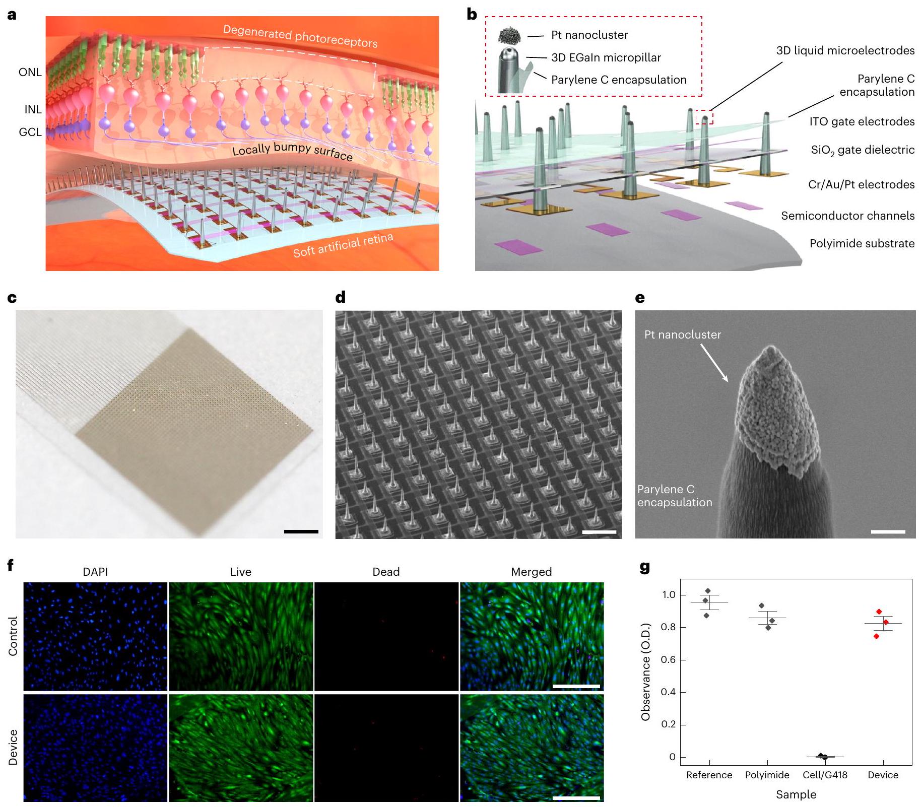
الأطراف الاصطناعية الشبكية الإلكترونية لتحفيز خلايا الشبكية تعد واعدة لاستعادة البصر. ومع ذلك، فإن الأقطاب الكهربائية الصلبة في الزرعات الشبكية التقليدية يمكن أن تسبب ضررًا على الأنسجة الرقيقة للشبكية. كما أن لديها انتقائية محدودة بسبب قربها السيئ من الخلايا المستهدفة في الشبكية المتدهورة. هنا نقدم شبكة اصطناعية ناعمة (سمك، حيث يتم دمج الترانزستورات الضوئية فائقة النحافة المرنة مع أقطاب التحفيز ثلاثية الأبعاد من سبيكة الغاليوم-إنديوم المذابة. تظهر تجمعات النانو من البلاتين المغلفة محليًا فقط على طرف هذه الأقطاب الكهربائية السائلة ثلاثية الأبعاد مزايا في تقليل مقاومة أقطاب التحفيز. يمكن أن تعزز هذه الأقطاب الدقيقة القرب من خلايا العقدة الشبكية المستهدفة وتوفر حقنات شحن فعالة. لإثارة الاستجابات العصبية في الشبكية. إن معامل يونغ المنخفض (234 كيلو باسكال)، بسبب شكلها السائل، يمكن أن يقلل من الضرر الذي يلحق بالشبكية. علاوة على ذلك، استخدمنا نهج تعلم آلي غير خاضع للإشراف لتحديد النبضات المستحثة بفعالية لتصنيف الأنشطة العصبية داخل خلايا العقدة الشبكية. تكشف نتائج التجارب الحية على نموذج الفأر المصاب بضمور الشبكية أن التوزيع الزماني المكاني للاستجابات العصبية على شبكيتهم يمكن رسمه تحت مناطق إضاءة محلية مختارة، مما يشير إلى استعادة رؤيتهم.

يمكن أن تسبب الأمراض التنكسية الشبكية، بما في ذلك التهاب الشبكية الصباغي والتنكس البقعي المرتبط بالعمر، فقدانًا تدريجيًا أو ضررًا دائمًا لخلايا المستقبلات الضوئية، مما يؤدي إلى ضعف شديد في الرؤية. ومع ذلك، يمكن الحفاظ على خلايا الشبكية الداخلية (الخلايا العقدية والخلايا ثنائية القطب) على الرغم من تنكس مستقبلات الضوء.
لقد ظهرت الأطراف الاصطناعية الشبكية الإلكترونية، التي تحفز كهربائيًا خلايا الشبكية الداخلية باستخدام أجهزة حساسة للضوء، كطريقة واعدة لاستعادة البصر. التفعيل الكهربائي لـ
يمكن للخلايا العصبية الشبكية أن تولد إدراكات بصرية (فوسفين) . تم تعديل هذا الجهاز ليستخدم مع الأشخاص المكفوفين بسبب تنكس الشبكية، على الرغم من أنه لا يزال محدودًا بحدة بصر منخفضة. توفر الأطراف الاصطناعية تحت الشبكية، الموضوعة بين الظهارة الصبغية للشبكية وطبقة المستقبلات الضوئية المتدهورة، تثبيتًا ميكانيكيًا مستقرًا للجهاز، لكنها تواجه درجة أكبر من الصعوبة الجراحية مع حجم زرع محدود. تشمل المخاطر المرتبطة بالزراعة تحت الشبكية أيضًا فقدان المستقبلات الضوئية المتبقية وصبغة الشبكية.
تمزق الظهارة. على الرغم من أن زراعة تحت الشبكية تُجرى بشكل روتيني في جراحة الزجاجية والشبكية، فإن البروستhesis الشبكية، الموضوعة داخل الزجاجية وتواجه جانب خلايا العقدة الشبكية (RGC)، قد أظهرت وعدًا في كل من الملاحظات السريرية طويلة وقصيرة الأمد. ومع ذلك، أثبتت النتائج أن أحد القيود الرئيسية ناتج عن عدم التوافق بين الشبكية والغرسة، حيث إن العتبة لإثارة الاستجابات الشبكية تعتمد على المسافة بين الإلكترود والخلايا. يمكن أن يؤدي القرب المنخفض الناتج عن هذه التباينات أيضًا إلى انتشار جانبي للمجال الكهربائي، مما يقلل من الدقة المكانية للتحفيز. يمكن أن يؤدي هذا التحفيز غير الدقيق على السطح الشبكي إلى إثارة محاور خلايا العقدة الشبكية، التي تمر بين الجهاز وخلايا العقدة الشبكية، مما يولد تصورات بصرية غير منتظمة للمرضى. لتحسين دقة التحفيز وتقليل تحفيز المحاور العصبية، من المهم إنشاء اتصال دقيق ومستقر وتقليل المسافة بين أجسام خلايا العقدة الشبكية المستهدفة وأقطاب التحفيز، مما يقلل من عتبات تنشيط أجسام خلايا العقدة الشبكية. ومع ذلك، فإن المرضى الذين يعانون من أمراض تنكس الشبكية الشديدة لديهم أسطح شبكية غير متجانسة محليًا، مما يمكن أن يخلق فجوة هندسية غير مرغوب فيها بين السطح الشبكي وأقطاب التحفيز. .
لمعالجة هذه القيود، تم دراسة الإلكترونيات الضوئية فائقة النحافة والمرونة لتثبيتها بشكل متوافق على السطح المنحني للشبكية. على الرغم من المرونة الكبيرة لهذه الأجهزة، فإن الأقطاب الكهربائية ذات الشكل المسطح تسبب فجوة هندسية عن سطح الشبكية المتعرج محليًا. في هذا الصدد، تُظهر الميكروأقطاب ثلاثية الأبعاد (3D) وعدًا في تحفيز الجهاز العصبي بشكل فعال، مما يقلل من مسافة الأقطاب الكهربائية عن الخلايا. أيضًا، يمكنها تحفيز مناطق محلية محددة عن طريق تجاوز الخلايا العصبية التي لا ينبغي تحفيزها، مما يوفر انتقائية ممتازة ودقة مكانية عالية. . ومع ذلك، تم تشكيل الأقطاب العصبية ثلاثية الأبعاد السابقة باستخدام مواد صلبة جامدة، مع عدم تطابق ميكانيكي كبير عند واجهتها مع الأنسجة البيولوجية اللينة. يمكن أن يتسبب ذلك في تلف الشبكية اللينة مباشرة، أو يؤدي إلى استجابات التهابية داخل الشبكية. .
هنا نقدم شبكية اصطناعية ناعمة حيث يتم دمج مصفوفات الترانزستورات المرنة والرقيقة والحساسة للضوء مع أقطاب التحفيز ثلاثية الأبعاد الناعمة من المعادن السائلة لاستعادة الرؤية. أولاً، بالمقارنة مع زراعة تحت الشبكية، يتم زراعة هذه الشبكية الاصطناعية الناعمة باستخدام طريقة زراعة فوق الشبكية الأكثر أمانًا مع تقليل التوغل في الشبكية. ثانيًا، تم طباعة المعادن السائلة الناعمة والمتوافقة حيويًا كأقطاب تحفيز بدقة عالية. تم إجراء دراسات على المعادن السائلة بما في ذلك خصائصها (انخفاض معامل المرونة وحدود المرونة اللانهائية) وطرق المعالجة (الطباعة والتشكيل) للاستفادة منها في الإلكترونيات. ومع ذلك، فإن البحث حول المواد الحيوية المستخدمة في واجهات البيولوجيا مثل المعادن السائلة (LM) لا يزال في مراحله الأولى. المعادن السائلة القائمة على الغاليوم، مثل سبيكة الغاليوم-إنديوم الإذابة (EGaIn)، تتميز بأنها لينة بطبيعتها وتظهر سمية منخفضة (الشكل التوضيحي التكميلي 1). بالمقارنة مع الأقطاب الكهربائية العمودية/المدببة السابقة التي تستخدم مواد صلبة، فإن هذه الأقطاب الكهربائية الناعمة ثلاثية الأبعاد تظهر معاملات مرونة منخفضة، مما يقلل من الأضرار غير المرغوب فيها لشبكية العين. . بالإضافة إلى ذلك، تظهر تجمعات النانو من البلاتين (Pt) المغلفة محليًا على طرف هذه الأقطاب الكهربائية LM مزايا فيما يتعلق بحقن الشحنات بشكل فعال في خلايا الشبكية العصبية. ثالثًا، يتم تطبيق التعلم الآلي على الإشارات الناتجة خلال تجارب الحيوانات، بحيث يمكن تحليل النبضات المستحثة من خلايا الشبكية العقدية (RGC). أخيرًا، أكدت التجارب الحية أن تضخيم الإشارة الناتج عن الإضاءة بالضوء المرئي يؤدي إلى استجابات في الوقت الحقيقي في خلايا RGC في المنطقة المحلية التي يتعرض فيها الضوء، وذلك لفئران الشبكية المتدهورة (rd1) التي تعاني من تدهور كبير في مستقبلات الضوء، مما يشير إلى استعادة رؤيتهم.

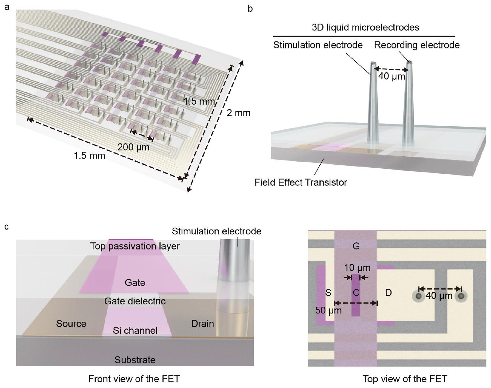
شبكية صناعية ناعمة مع مصفوفات ميكروإلكترود ثلاثية الأبعاد

الشكل 1أ يظهر شبكية اصطناعية مع مجسات ميكروإلكترونية ثلاثية الأبعاد قريبة من السطح الشبكي غير المتجانس والمتدهور. تم لصق هذا الجهاز الرقيق والمرن بشكل متوافق على السطح الشبكي الداخلي، وكانت المجسات البارزة على شكل أعمدة من المواد اللينة تحفز خلايا العقدة الشبكية مباشرة. الشكل 1ب يوضح المخطط لـ
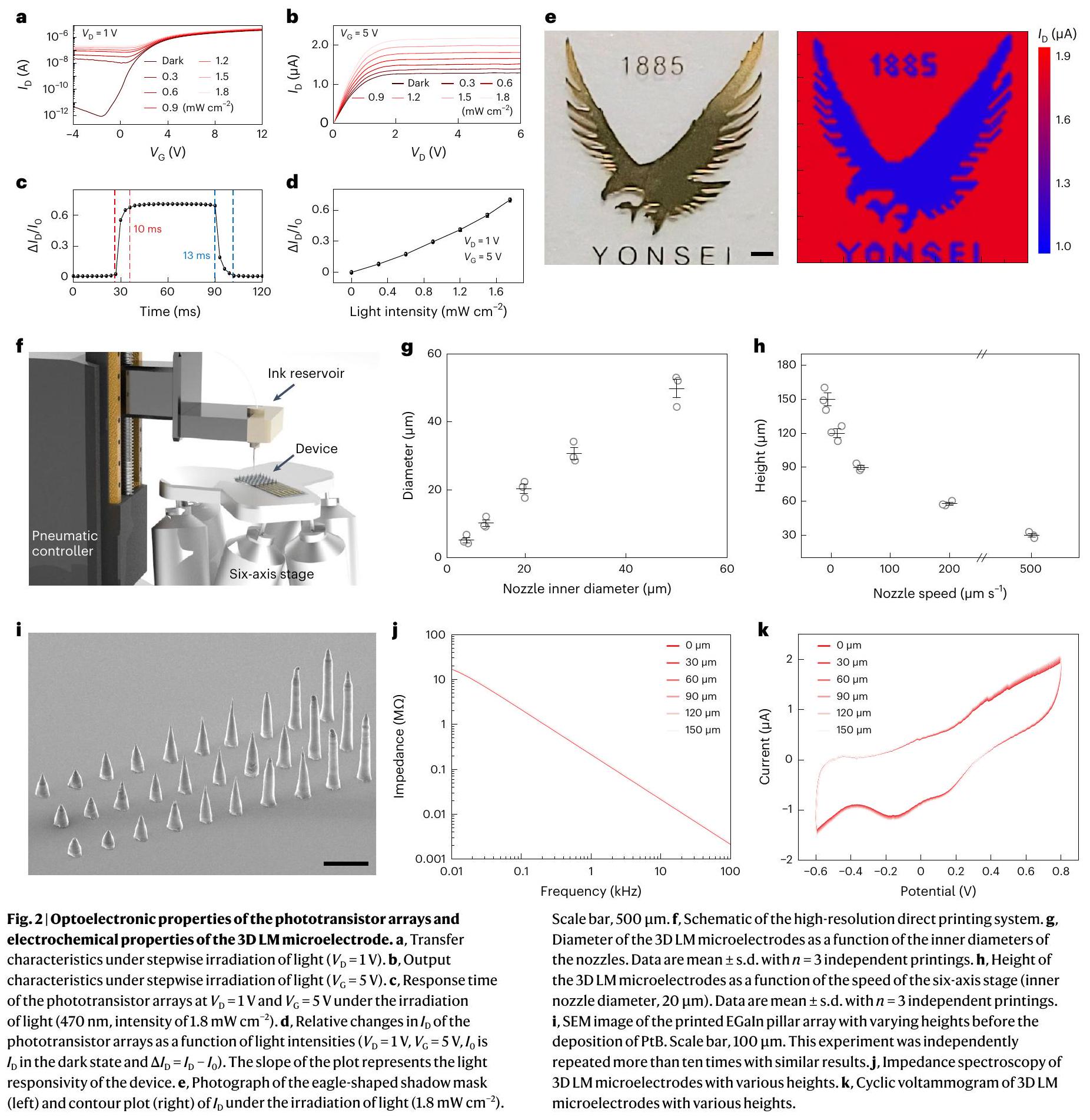
تخطيط الجهاز. تم طباعة مصفوفة الأعمدة الدقيقة ثلاثية الأبعاد EGaln مباشرة على أسطح أقطاب التصريف للترانزستورات الضوئية لتشكيل أقطاب التحفيز في درجة حرارة الغرفة. ثم تم تغليف جدران الأعمدة الجانبية بطبقة من باريلين C. تم فتح أطراف الأعمدة باستخدام تقنية غير متجانسة. نقش الأيونات التفاعلية (RIE) كمواقع حقن الشحنة في الأنسجة الشبكية قبل الطلاء الكهربائي لكتل النانو من البلاتين، المشار إليها باسم Ptblack (PtB) (الشكل التمديدي 1). تصف الطرق عمليات التصنيع بالتفصيل. يضيف هذا الطلاء PtB خشونة على مقياس النانومتر إلى هذه الأقطاب الكهربائية الدقيقة ثلاثية الأبعاد، مما يزيد بشكل كبير من مساحتها السطحية الكهروكيميائية. عندما يتم تسليط الضوء الخارجي على الترانزستور الضوئي، يتم توليد تيار ضوئي داخل قناة أشباه الموصلات، مما يؤدي إلى تضخيم تيار التصريف الخاص به. . هذا المعزز الناتج عن الضوء الساقط يشير إلى الزيادة الكبيرة في حقن الشحنات في خلايا العقدة الشبكية من خلال الميكروإلكترود ثلاثي الأبعاد مع محفزات نبضية لجهد التصريف ( ). ثم يمكن توصيل إمكانات العمل المستحثة داخل خلايا الشبكية العصبية (RGCs) إلى العصب البصري، مما يعوض المعلومات البصرية. الشكل 1c يظهر هذه الشبكية الاصطناعية حيث تم دمج مصفوفة ترانزستورات عالية الدقة مع الأقطاب الكهربائية الدقيقة ثلاثية الأبعاد (3D LM). في هذه العينة، هذه الأقطاب الكهربائية الدقيقة ثلاثية الأبعاد (الارتفاع، ; القطر، تم تشكيل ( ) في كل قطب تصريف من مجموعة الترانزستورات هذه (الشكل 1d والشكل التكميلي 2). يوضح الشكل 1e الطلاء المحلي لـ PtB على طرف الميكروإلكترود ثلاثي الأبعاد LM. لم يغير هذا بشكل ملحوظ معامل المرونة لـ EGaln المطبوعة ثلاثي الأبعاد، والذي كان قابلاً للمقارنة مع الأنسجة البيولوجية وأقل بكثير من الأقطاب الصلبة الثابتة (الشكل التكميلي 3). من ناحية أخرى، كانت زراعة هذه الأقطاب التقليدية على المدى الطويل محدودة بسبب الأضرار الكبيرة التي تلحق بأنسجة الشبكية الحساسة عند التفاعل معها. على الرغم من أن زراعة Argus أظهرت أنها تعمل بعد عشر سنوات من الزراعة، فقد تم الإبلاغ عن تناقضات بين سطح الشبكية ومكونات الجهاز الصلبة. زادت هذه التباينات من الفجوة الهندسية بينهما، مما أدى إلى انخفاض كبير في المقاومة ولكن زيادة في عتبة التحفيز، مما يحد من التحفيز الفعال للشبكية. .
قمنا بإجراء اختبار حيوية الخلايا باستخدام اختبار الخلايا الحية/الميتة مع خلايا الصباغ الشبكي البشري. كانت الفروق في نسبة الخلايا الحية/الميتة بين الجهاز والمرجع على مدار سبعة أيام ضئيلة (الشكل 1f). كانت نسبة بقاء الخلايا للجهاز هي (الشكل 1g). كما أجرينا اختبار موت الخلايا المبرمج في المختبر باستخدام تحليل تدفق الخلايا، وكانت 98.3% من الخلايا المزروعة على الجهاز خلايا حية (الشكل التوضيحي 4). هذه النتائج تلبي معيار السمية الخلوية في المختبر (>80%) للأجهزة الطبية. .
لضمان التوافق الحيوي للجهاز مع الأقطاب الكهربائية الدقيقة ثلاثية الأبعاد، تم إجراء اختبارات متنوعة تتعلق بالسمية المناعية والعصبية بعد خمسة أسابيع من الزرع في فئران rd1 الحية. ). أولاً، أظهرت المراقبة لمدة خمسة أسابيع لقاع العين عدم وجود علامات على النزيف أو الالتهاب أو إعتام عدسة العين على الرغم من زراعة الجهاز (الشكل التكميلي 5). بعد ذلك، كشفت اختبار المناعة الكيميائية عن عدم وجود انخفاض في الفلورية يدل على خلايا العقدة الشبكية وعدم تراكم البلعميات والميكروغليا (الشكل التكميلي 6). كما أظهرت الصور ثلاثية الأبعاد المأخوذة بواسطة التصوير التداخلي لشبكية الفأر الكاملة على الجهاز عدم وجود تراكم للبلعميات والميكروغليا حولها (الشكل التكميلي 7). ثالثًا، تم زراعة الجهاز على سطح الشبكية دون ميل أو انهيار مع وجود أطراف ميكروإلكترود ثلاثية الأبعاد موضوعة على طبقة خلايا العقدة الشبكية دون وجود أي أورام خبيثة أو التهاب (الشكل التكميلي 8أ). أخيرًا، أكدنا أن الجهاز لم يؤثر بشكل كبير على سمك الشبكية (الشكل التكميلي 8ب). توفر الطرق التكميلية مزيدًا من التفاصيل حول التوافق الحيوي للشبكية الاصطناعية.

توصيفات الشبكية الاصطناعية اللينة

التيار-الجهد ) خصائص ( الشكل 2أ، ب) للترانزستور الضوئي في الشبكية الاصطناعية أظهرت سلوكيات نموذجية لترانزستور التأثير الميداني الحساس للضوء مع كثافات ضوئية مختلفة (الشكل التكميلي 9). تم حساب حركة التأثير الميداني في ظروف البيئة المحيطة كـ نسبة التشغيل/الإيقاف ) وجهد العتبة ( )
الشكل 1| شبكية اصطناعية ناعمة مع مصفوفات ميكروإلكترود ثلاثية الأبعاد. أ، مخطط للشبكية الاصطناعية المدمجة مع الميكروإلكترودات ثلاثية الأبعاد بالقرب من السطح الشبكي المتعرج محليًا، بسبب تدهور مستقبلات الضوء. تشير ONL وINL وGCL إلى الطبقة النووية الخارجية، الطبقة النووية الداخلية وطبقة خلايا العقدة، على التوالي. مخطط تخطيطي لتصميمات الشبكية الاصطناعية المستندة إلى دمج الترانزستورات الحساسة للضوء مع الأقطاب الكهربائية الدقيقة ثلاثية الأبعاد. ج، صورة للشبكية الاصطناعية حيث تم دمج مصفوفة الترانزستورات عالية الدقة مع الأقطاب الكهربائية الدقيقة ثلاثية الأبعاد. مقياس الرسم، 1 مم. د، صورة مجهر إلكتروني مسح ضوئي (SEM) لمصفوفات الترانزستورات الضوئية عالية الدقة. بكسلات؛ مسافة البكسل، ) مع
أقطاب ميكروية ثلاثية الأبعاد الارتفاع قبل إيداع طبقة التغطية العليا من باريلين C. شريط القياس، . تم تكرار هذه التجربة خمس مرات مع نتائج مشابهة. الصورة المجهرية الإلكترونية الماسحة (SEM) لمجموعات نانو البلاتين (PtB) المغلفة محليًا فقط على طرف قطب التحفيز ثلاثي الأبعاد. مقياس الرسم، . تم تكرار هذه التجربة بشكل مستقل أكثر من عشر مرات مع نتائج مماثلة. ف، صور مجهرية تمثيلية للفلوريسنس لصبغة DAPI وصبغة الحياة/الموت لخلايا شبكية العين البشرية المزروعة على الجهاز مع أقطاب ميكروية ثلاثية الأبعاد. قضبان القياس، . تم تكرار هذه التجربة بشكل مستقل ثلاث مرات مع نتائج مشابهة. ج، حيوية الخلايا في الشبكية الاصطناعية. O.D.، الكثافة الضوئية. البيانات هي متوسط س.د. مع تجارب مستقلة.
كانوا و 2.6 فولت، على التوالي (الشكل التكميلي 10). أظهر الفوتوترانزستور استجابة سريعة ووقت استرداد قدره 10 و 13 مللي ثانية، على التوالي، مع تاريح ضئيل (الشكل 2c). التغير النسبي في هذا الفوتوترانزستور ( ) كان متناسبًا خطيًا مع شدة الضوء الساقط (الشكل 2d؛ هو في الحالة المظلمة و ). الشكل التوضيحي الإضافي 11 يقدم التغير النسبي في كنتيجة لطول موجة الضوء. سمح مصفوفة الفوتوترانزستور بتصور الضوء الذي يمر عبر نمط قناع ظل على شكل نسر أثناء إضاءة الضوء (الشكل 2e والطرق التكميلية).
لصنع مصفوفة أقطاب ميكروإلكترونية ثلاثية الأبعاد على شكل أعمدة كأقطاب تحفيز، استخدمنا طريقة الطباعة المباشرة مع نظام طباعة عالي الدقة (الشكل 2f). تصف الطرق عمليات الطباعة بالتفصيل. يمكن تحديد قطر عمود EGaln بواسطة القطر الداخلي لفوهة الكابيلاري الزجاجية (الشكل 2g). يمكن تشكيل ارتفاع العمود بطريقة قابلة للتحكم من خلال ضبط سرعة النزول العمودي للمنصة (الشكل 2h,i والشكل الإضافي 2). أيضًا، أظهرت الأعمدة المطبوعة، باستخدام أقطار فوهات مختلفة، ارتفاعات كافية لاستهداف خلايا الشبكية (الشكل التكميلي 12).
تم طلاء PtB محليًا فقط على أطراف EGalntips الخاصة بهم باستخدام طريقة الطلاء الكهربائي (الشكل البياني الممتد 3 والطرق) وتم تثبيت الميكروإلكترودات ثلاثية الأبعاد بشكل موثوق على أقطاب التصريف خلال عمليات ما بعد الطباعة (الشكل التوضيحي التكميلي 13). تم إجراء تحليل طيف الامتداد الكهربائي والجهد الدوري لمقارنة خصائص المقاومة وسعة تخزين الشحن لهذه الأقطاب (الشكل التوضيحي التكميلي 14). كانت أبعاد أطرافهم المطلية بـ PtB متطابقة (القطر، ؛ المساحة السطحية الهندسية، )، مع اختلاف واحد فقط في ارتفاعاتها. أظهرت أقطاب عمود PtB-coated EGaln ثلاثي الأبعاد (PtB/EGaln) مقاومة قدرها (عند 1 كيلوهرتز)، تقريبًا أقل بثلاث مرات من حالة عدم طلاء PtB
(الشكل التوضيحي 15). المقاومة وسعة تخزين الشحن )، المحسوبة من منحنيات الفولتمترية الدورية، لم تتغير بشكل ملحوظ مع ارتفاع العمود (الشكل 2j، k). قمنا بمقارنة المقاومة (عند 1 كيلو هرتز) وسعة تخزين الشحنة مع المواد المستخدمة في الواجهات العصبية (الأشكال التكميلية 16 و 17). يمكن أن تكون هذه الخصائص المستقلة عن الارتفاع مفيدة للتحفيز المتسق للخلايا المستهدفة باستخدام ميكروإلكترودات LM ثلاثية الأبعاد ذات ارتفاعات متغيرة. قمنا بتسجيل النبضة التحفيزية باستخدام الإلكترود المسجل، الموضوع بجوار الإلكترود التحفيزي، وأكدنا أن سعة النبضة زادت بشكل متناسب مع شدة الضوء، مما يثبت أن الجهاز يعمل كمنبه استجابة للضوء (الشكل التكميلية 18).

تجارب كهربائية فيزيولوجية خارج الجسم

الاستجابات في شبكية العين لكل من الفئران من النوع البري (WT) وفئران rd1 تم اختبارها عن طريق التحفيز الكهربائي باستخدام الشبكية الاصطناعية مع ميكروإلكترودات ثلاثية الأبعاد (الارتفاع، ; الشكل 3أ). لتسجيل الاستجابات الشبكية المستحثة بصريًا أو كهربائيًا، تم وضع كل إلكترود تسجيل بجوار (المسافة، ) إلى كل قطب تحفيز (الشكل 3ب). تم وضع الشبكيات المعزولة من فئران WT و rd1 على الجهاز، مع توجيه المجسات الدقيقة ثلاثية الأبعاد نحو جانب خلايا العقدة الشبكية من الشبكية. توفر الطرق التفاصيل التجريبية لهذه التجربة خارج الجسم. قبل الزرع، تم تجميد الجهاز على الفور لتحويل EGaln في الحالة السائلة إلى حالة صلبة عن طريق تركه في التخزين البارد (أقل من نقطة انصهار EGaln، أي، ). عادت الأقطاب الدقيقة ثلاثية الأبعاد إلى الطور السائل ولم تنهار بعد الزرع في الشبكية. بالنسبة للتحفيز الكهربائي، تم تشغيل ترانزستور الجهاز تحت حالة محددة ( انحياز تيار مستمر قدره 5 فولت؛ bias نبضي بقيمة 1 فولت لمدة 1 مللي ثانية وتردد 10 هرتز)، وتمت التسجيلات باستخدام الأقطاب الكهربائية المجاورة. نظرًا لأن الفئران ثنائية اللون من الثدييات ولديها نوعان فقط من المخاريط (حساسان للضوء الأزرق والأخضر) تم استخدام الضوء الأزرق (470 نانومتر). تم تسجيل الجهود الكهربائية المستحثة بصريًا (VEPs) تحت هذا التعرض للضوء دون تشغيل الجهاز، بينما تم تسجيل الجهود الكهربائية المستحثة كهربائيًا (EEPs) مع تشغيل الجهاز في حالة الظلام. لم يُحدث الضوء استجابات شبكية داخل شبكية الفأر rd1 (الشكل 3c). ومع ذلك، فإن التحفيز الكهربائي أثناء تشغيل الجهاز يمكن أن يستحث طفرات خلايا العقدة الشبكية (RGC) مع حجم EEP قابل للمقارنة في كل من WT ( ) و شبكية عيون الفئران. عندما تم توصيل تحفيز كهربائي بجرعة واحدة لكل من شبكية عيون الفئران الطبيعية (WT) والفئران rd1 (في حالة الظلام)، أظهرت الأنشطة الشبكية المسجلة للفئران rd1 زيادة مبكرة وأكثر وضوحًا في نشاط الإطلاق مقارنةً بحالة الفئران الطبيعية (WT) (الشكل 3d). التغيرات الشكلية في شبكية عيون الفئران rd1، بما في ذلك تقليل حجم خلايا العقدة الشبكية (RGC) وسمك الطبقة النووية الداخلية، معروفة بتأثيرها على الخصائص الوظيفية لخلايا العقدة الشبكية، مما يؤدي إلى زيادة عتبة التحفيز وتأخير مطول. . تم استنباط الاستجابات الكهربائية المحرضة أثناء تشغيل الجهاز باستخدام قطب كهربائي من نوع السطح المسطح (الارتفاع، ) لشبكية عيون الفئران WT و rd1، على التوالي، أثناء الإضاءة الضوئية مع كثافات مختلفة (الشكل 3e، f). زادت معدلات إطلاق النبضات العصبية المستحثة من خلايا العقدة الشبكية (RGC) بشكل متناسب مع كثافة الضوء في شبكيات عيون كل من الفئران WT و rd1 (الشكل 3g). أظهرت شبكية عيون الفئران WT معدل إطلاق أعلى بسبب الاستجابات الطبيعية من طبقة المستقبلات الضوئية الطبيعية، مقارنةً بحالة rd1.
للمقارنة مع حالة القطب الكهربائي ذو السطح المسطح، تم إجراء تجارب مماثلة باستخدام جهاز يحتوي على ارتفاعات مختلفة من الميكروأقطاب ثلاثية الأبعاد (الشكل 3h,i). على الرغم من الخصائص الكهروكيميائية المستقلة عن الارتفاع، زادت الأقطاب ذات الهيكل العمودي من نشاط إطلاق النار لخلايا العقدة الشبكية أثناء التحفيز الكهربائي (الشكل 3j). انخفض معدل الإطلاق مرة أخرى عندما تجاوز ارتفاع العمود بالنظر إلى سمك طبقات الشبكية (الجدول التكميلي 1)، قد يكون هذا ناتجًا عن استهداف غير صحيح لخلايا العقدة الشبكية حيث مرت طرف المحفز عبر خلايا العقدة المستهدفة. على الرغم من أن تغيير القطبية قد يحفز الخلايا المستهدفة بشكل غير صحيح، فإن تصنيع ميكروإلكترودات ثلاثية الأبعاد بارتفاعات مثالية يسمح لطرف الإلكترود بالتواصل مباشرة مع الخلايا المستهدفة.
الشكل 3 | تجربة خارج الجسم باستخدام شبكية عين الفأر WT و rd1. أ، مخطط لإعداد التجربة لتجربة خارج الجسم باستخدام شبكية عين الفأر WT و rd1. ب، صورة مجهرية ضوئية لجهاز يتكون من 36 زوجًا من الأقطاب الكهربائية ثلاثية الأبعاد للتحفيز والتسجيل (المسافة بين الأقطاب، مقياس، . c، VEP و EEP لشبكية الفأر WT و rd1. البيانات هي متوسط س.د. مع فئران مستقلة بيولوجيًا. تم حساب الأهمية باستخدام اختبار أحادي الذيل غير متزاوج. -اختبار: (ن.س.) (، اليسار)، (“، صحيح). د، EEPs لشبكية عين الفأر WT و rd1 (عرض النبضة، 1 مللي ثانية؛ التيار، ) في الحالة المظلمة. الخط الأحمر المتقطع يشير إلى بدء التحفيز. e، EEPs لشبكية عين الفأر WT تحت تعرض للضوء (470 نانومتر) مع كثافات مختلفة أثناء تشغيل الشبكية الاصطناعية مع أقطاب تحفيز من نوع السطح المسطح.

معالجة الإشارات باستخدام التعلم الآلي

نظرًا لتعقيد الأنشطة الشبكية، استخدمنا التعلم الآلي غير المراقب لمعالجة هذه الإشارة. للتصنيف الأساسي، تم تصنيف 4,992 من النبضات من خلال التجميع الهرمي، من خلال تعيين قيم النبضات الشبكية كبيانات إدخال. تم تصنيف البيانات المعطاة إلى مجموعات مميزة وفقًا لحجم وشكل الإشارة (الشكل 4أ). ثم قمنا بإجراء تجميع -means ، مع تصنيف الإشارات بشكل أساسي كبيانات إدخال. عدد المجموعات ( تم تحسين ) إلى 4 من خلال طريقة الكوع ومعامل السيلويت، حيث تم استخدام النقاط C و D المميزة في الرسم البياني كمعايير للتصنيف. نتيجة لذلك، تم تصنيف بيانات النبضات الشبكية إلى أربعة مجموعات ذات قيم محتملة مختلفة (الشكل 4ب والطرق التكميلية). تم تحليل هذه النبضات الشبكية المصنفة بواسطة التعلم الآلي غير المراقب للحصول على الإشارات المتوسطة مع انحرافاتها المعيارية. أظهرت الإشارات داخل نفس المجموعة للمجموعات 1 و2 و3 شكلًا مشابهًا ومدة زمنية متشابهة للقيم المحتملة (الشكل 4ج-هـ).
عند تحفيز جسم الخلية العصبية الشبكية، يظهر استجابة ناتجة عن تسجيل خارجي للنشاط الكهربائي نمطًا نموذجيًا يتمثل في انخفاض سريع (إزالة الاستقطاب) يتبعه زيادة (إعادة الاستقطاب) في إمكانات الغشاء، بينما تظهر محاور الخلايا العصبية الشبكية استجابة ناتجة عن النشاط الكهربائي معاكسة لذلك. تظهر أشكال الموجات لإشارات خلايا العقدة الشبكية (RGC) المصنفة، المسجلة مباشرة بعد التحفيز الكهربائي باستخدام أقطاب دقيقة ثلاثية الأبعاد (3D LM)، استجابات خلايا العقدة الشبكية الجسيمية مع إزالة استقطاب دون المللي ثانية. تشير هذه النتائج إلى إمكانية التحفيز الانتقائي لجسيمات خلايا العقدة الشبكية باستخدام أقطاب دقيقة ثلاثية الأبعاد. على الرغم من أنه لا يمكن القضاء على التحفيز المحوري، إلا أن هذا التحفيز الانتقائي لجسيمات خلايا العقدة الشبكية يحمل إمكانية تقليل تنشيط المحاور، مما يؤدي إلى رؤية أكثر طبيعية مع إدراك أقل عدم انتظام.

استعادة الرؤية في الجسم الحي لفئران rd1 الحية

تم زرع جهاز شبكية صناعية مزود بميكروإلكترودات ثلاثية الأبعاد في الفئران rd1 الحية في الجسم الحي. ). قبل هذه التجربة، أكدنا أن طبقة المستقبلات الضوئية كانت متدهورة بالكامل (الشكل التكميلي 19). بعد تثبيت الجهاز مع التوصيلات الخارجية (الشكل التكميلي 20)، تم تطبيق إما (1) إضاءة كاملة المجال (470 نانومتر) أو (2) تعرض مستمر لليزر (415 نانومتر) من خلال قناع ظل بنمط إهليلجي على قاع العين. كان هذا الجهاز مثبتًا جيدًا على سطح الشبكية دون أي ضرر ملحوظ أو نزيف (الشكل 5أ). تشير صورة التصوير البصري التماسي المقطعي التي تم الحصول عليها بعد هذه الجراحة إلى أن الميكروإلكترودات ثلاثية الأبعاد من نوع LM كانت محاطة بشكل متوافق بأنسجة الشبكية دون انهيارها (الشكل 5ب). قمنا بمزيد من التحقيق في انهيار الميكروإلكترودات ثلاثية الأبعاد من نوع LM بعد الزرع، من خلال قياس زاوية ميل الأعمدة من صور التصوير البصري التماسي المقطعي بعد زرع 180 إلكترودًا في المجمل في شبكية الفئران rd1 ( )، وأكدت أن الأقطاب الكهربائية المزروعة لم تنهار (الشكل التوضيحي 21).
تم تسجيل EEPs عن طريق إسقاط الضوء المرئي على شبكية العين بعد زراعة الشبكية الاصطناعية (الشكل 5c والشكل الإضافي 4). تم تسجيل آثار فورية للجهود ومعدلات إطلاق النبضات المستحثة تحت إضاءة ضوئية ثابتة، وتم رسم خرائط لمعدلات الإطلاق مكانيًا خلال هذه الإضاءة (الشكل 5d، e). تم تسجيل
أظهرت الاستجابات أحجامًا محتملة ومعدلات إطلاق متسقة من النبضات المستحثة مقارنةً بالحالة التي لا تتضمن إضاءة الضوء (الأشكال التكميلية 22 و23)، مما يشير إلى وجود تجانس جيد عبر المنطقة الشبكية المحفزة باستخدام الجهاز.
أحد التحديات الرئيسية في تطوير استعادة الرؤية الاصطناعية هو التعرف على الأجسام. لقد أظهرنا الاستجابات من الشبكية المتدهورة، من خلال التعرض الانتقائي للمناطق المحلية باستخدام ليزر من خلال قناع ظل على شكل إهليلجي (الشكل 5f).
الشكل 4 | تصنيف الإشارات باستخدام التعلم الآلي غير المراقب. أ، تم تصنيف نبضات خلايا العقدة الشبكية المستحثة بشكل أساسي من خلال التجميع الهرمي. تمثل الخطوط السوداء النقاط و ، التي توفر المعايير للتجمع الثانوي. ب، مجموعات البيانات المصنفة من -يعني التجميع. ج، تم تصنيف بيانات جميع نبضات خلايا الشبكية المستحثة كعنقود 1، مرتبة بناءً على حجمها وشكلها (يسار)، بالإضافة إلى متوسط نبضات خلايا الشبكية لعنقود 1 (يمين). البيانات هي متوسط س.د. مع فئران مستقلة بيولوجيًا. د، البيانات الكاملة لنبضات خلايا العقدة الشبكية المستحثة

مصنفة كعنقود 2، مرتبة على أساس حجمها وشكلها (يسار)، ومتوسط نبضات خلايا العقدة الشبكية (RGC) للعنقود 2 (يمين). البيانات هي متوسط س.د. مع فئران مستقلة بيولوجيًا. البيانات الكاملة لنبضات خلايا العقدة الشبكية المستحثة المصنفة كعنقود 3، مرتبة بناءً على حجمها وشكلها (يسار)، بالإضافة إلى متوسط نبضات خلايا العقدة الشبكية لعنقود 3 (يمين). البيانات هي متوسط س.د. مع فئران مستقلة بيولوجياً.
أظهرت المنطقة المحلية المضيئة استجابات شبكية أكبر نسبيًا، مقارنةً بالمنطقة في الحالة المظلمة (الشكل 5g). عندما يتم تحفيز محاور خلايا العقدة الشبكية كهربائيًا، يمكن أن يحدث انتشار عكسي للتحفيزات الكهربائية، مما يؤدي إلى استجابة خاطئة لخلايا العقدة الشبكية في الظلام.
ومع ذلك، كانت التوزيعة المكانية لمعدلات إطلاق النار القصوى (أي، المجال الاستقبالي) مشابهة جدًا للشكل البيضاوي لهذا الإضاءة (الشكل 5h). أيضًا، تظهر نبضات خلايا الشبكية العقدية المرتبة (الشكل التوضيحي 24) شكل موجة نموذجي لاستجابة خلايا الشبكية العقدية الجسدية مشابهة.
الشكل 5| تجربة حية باستخدام فئران rd1 حية لاستعادة الرؤية. أ،
صورة للإعداد التجريبي في الجسم الحي باستخدام فأر rd1 الحي. الصورة المرفقة تظهر صورة قاع العين لفأر rd1 حي مع زراعة الجهاز. مقياس الرسم، رسم تخطيطي (يسار) وصورة تصوير تماسك بصري (يمين) لشبكية عين فأر rd1 بعد زراعة الجهاز. قضبان القياس، . ج، مخطط التجربة في الجسم الحي تحت إضاءة ضوء أزرق كامل المجال (طول الموجة، 470 نانومتر؛ الشدة، ). تُظهر الصورة المرفقة صورة قاع العين لفأر rd1 حي مع الجهاز المزروع تحت إضاءة زرقاء كاملة المجال. الصورة المشوهة ناتجة عن انكسار الضوء من الجسم الزجاجي الاصطناعي. شريط القياس، . د، سلسلة النبضات ومعدل إطلاق نبضات خلايا الشبكية المستحثة أثناء تشغيل الجهاز تحت إضاءة زرقاء كاملة المجال ثابتة. شريط القياس، 200 مللي ثانية (أفقي)؛ (يسار، عمودي)؛ 40 هرتز (يمين، عمودي). e، مخطط كونتور لمعدلات إطلاق نبضات خلايا الشبكية المستحثة تحت إضاءة ضوء أزرق كامل المجال. f، مخطط لتجربة الحيوان في الجسم الحي تحت ظروف مستمرة.
تعرض الليزر (طول الموجة، 415 نانومتر؛ الشدة، ) من خلال قناع ظل بنمط إهليلجي. الصورة المرفقة تظهر صورة قاع العين لفأر rd1 حي مع الجهاز المزروع تحت تعرض مستمر لليزر من خلال قناع ظل بنمط إهليلجي. شريط القياس، سلسلة النبضات ومعدل إطلاق نبضات خلايا الشبكية المستحثة خلال تشغيل الجهاز تحت تعرض مستمر لليزر من خلال قناع ظل بنمط إهليلجي. شريط القياس، 200 مللي ثانية (أفقي)؛ (يسار، عمودي)؛ 40 هرتز (يمين، عمودي). h، رسم بياني للخطوط المتساوية لمعدلات إطلاق النبضات العصبية المستحثة تحت إضاءة الليزر المنقوش. فهرس بكسلات الشبكية الاصطناعية. يشير الشكل البيضاوي الملون إلى نقطة الإضاءة المحلية لليزر. j ، معدلات إطلاق النار لجميع البكسلات في حالة الإضاءة بالليزر وحالة عدم الإضاءة بالليزر. تدل أشرطة الخطأ على الانحراف المعياري. تم حساب الأهمية باستخدام اختبار غير متزاوج أحادي الاتجاه. -اختبار: (****). ك، معدل إطلاق النار المُعَدل مع ثلاث حالات مختلفة من إضاءة الليزر في كل بكسل. البيانات هي متوسط س.د. مع فئران مستقلة بيولوجياً.
لنتائج ex vivo (الشكل 4). لمقارنة الاستجابات الشبكية بشكل كمي في المنطقة المضيئة بالليزر والمنطقة غير المضيئة بالليزر (أي الحالة المظلمة)، تم وضع علامة على موقع كل إلكترود تسجيل (بكسل) كفهرس (الشكل 5i). ثم تم حساب متوسط معدلات الإطلاق القصوى المسجلة من البكسلات المضيئة بالكامل (الفهارس 1-9) والبكسلات في الحالة المظلمة (الفهارس 16-36). كانت نشاط خلايا العقدة الشبكية في المناطق المعرضة بالكامل أعلى بحوالي أربع مرات من نشاط خلايا العقدة الشبكية الخلفية.

الاستنتاجات

لقد أبلغنا عن شبكية اصطناعية ناعمة تتكون من مصفوفات فوتوترانزستورات مرنة عالية الدقة مع أقطاب كهربائية دقيقة مطبوعة ثلاثية الأبعاد قادرة على التحفيز الشبكي الحد الأدنى من التدخل. أظهرت التجارب الحية أن الإضاءة بالضوء المرئي أدت إلى نشاطات متفجرة في خلايا العقدة الشبكية في المنطقة المحلية من الشبكية حيث كان الضوء موجودًا، مما يشير إلى إمكانية استعادة الرؤية في الفئران الحية من نوع rd1. يمكن أن تحمل هذه النتائج معنى تنبؤي في تطوير شبكيات اصطناعية مخصصة للمرضى الذين يعانون من تدهور غير متساوٍ في الشبكية.
على الرغم من أن الجهاز المستخدم في التجربة الحية كان محدودًا بـ 36 بكسل بسبب صغر حجم عين الفأر (القطر، 3 مم)، فإن التوسعات الإضافية في حجم الجهاز وزيادة عدد البكسلات ستتيح تطبيقه على نموذج حيواني كبير ذو عيون أكبر وشبكية أكثر سمكًا. بالإضافة إلى ذلك، كان نظام الطباعة لدينا قادرًا على تقليل قطر الأقطاب الكهربائية الدقيقة ثلاثية الأبعاد إلى جهاز عالي الدقة مزود بأقطاب ميكروية ثلاثية الأبعاد، والذي يتوافق نظريًا مع يمكن تصنيع الرؤية (الشكل البياني الممتد 5) تقليل حجم electrode التحفيز أمر حاسم لتحقيق تحفيز عالي الدقة. ومع ذلك، مع انخفاض حجم موقع التحفيز، تزداد المقاومة، مما يحد من فعالية التحفيز. يمكن أن تكون الدراسات الإضافية حول المواد النانوية (على سبيل المثال، تجمعات النانو من البلاتين)، التي تعزز فعالية التحفيز من خلال إضافة خشونة على مقياس النانومتر إلى سطح electrode، عملاً مثيرًا للاهتمام في المستقبل لتحقيق دقة بصرية أعلى.

المحتوى عبر الإنترنت

أي طرق، مراجع إضافية، ملخصات تقارير Nature Portfolio، بيانات المصدر، بيانات موسعة، معلومات تكميلية، شكر وتقدير، معلومات مراجعة الأقران؛ تفاصيل مساهمات المؤلفين والمصالح المتنافسة؛ وبيانات توفر البيانات والرموز متاحة علىhttps://doi.org/10.1038/s41565-023-01587-w.

References

  1. He, S., Dong, W., Deng, Q., Weng, S. & Sun, W. Seeing more clearly: recent advances in understanding retinal circuitry. Science 302, 408-411 (2003).
  2. Bloch, E., Luo, Y. & da Cruz, L. Advances in retinal prosthesis systems. Ther. Adv. Ophthalmol. 11, 2515841418817501 (2019).
  3. Lee, G. J., Choi, C., Kim, D.-H. & Song, Y. M. Bioinspired artificial eyes: optic components, digital cameras, and visual prostheses. Adv. Funct. Mater. 28, 1705202 (2018).
  4. Sahel, J.-A. et al. Partial recovery of visual function in a blind patient after optogenetic therapy. Nat. Med. 27, 1223-1229 (2021).
  5. Rao, Z. et al. Curvy, shape-adaptive imagers based on printed optoelectronic pixels with a kirigami design. Nat. Electron. 4, 513-521 (2021).
  6. Ko, H. C. et al. A hemispherical electronic eye camera based on compressible silicon optoelectronics. Nature 454, 748-753 (2008).
  7. Lorach, H. et al. Photovoltaic restoration of sight with high visual acuity. Nat. Med. 21, 476-482 (2015).
  8. Mathieson, K. et al. Photovoltaic retinal prosthesis with high pixel density. Nat. Photon. 6, 391-397 (2012).
  9. Tang, J. et al. Nanowire arrays restore vision in blind mice. Nat. Commun. 9, 786 (2018).
  10. Jang, J. et al. Implantation of electronic visual prosthesis for blindness restoration. Opt. Mater. Express 9, 3878-3894 (2019).
  11. Maya-Vetencourt, J. F. Subretinally injected semiconducting polymer nanoparticles rescue vision in a rat model of retinal dystrophy. Nat. Nanotechnol. 15, 30 (2020).
  12. Mandel, Y. et al. Cortical responses elicited by photovoltaic subretinal prostheses exhibit similarities to visually evoked potentials. Nat. Commun. 4, 1980 (2013).
  13. Sachs, H. G. & Gabel, V.-P. Retinal replacement-the development of microelectronic retinal prostheses-experience with subretinal implants and new aspects. Graefe’s Arch. Clin. Exp. Ophthalmol. 242, 717-723 (2004).
  14. Yue, L. et al. Ten-year follow-up of a blind patient chronically implanted with epiretinal prosthesis Argus I. Ophthalmology 122, 2545-2552.e1 (2015).
  15. Xie, H. et al. Monitoring cortical response and electrode-retina impedance under epiretinal stimulation in rats. IEEE Trans. Neural Syst. Rehabil. Eng. 29, 1178-1187 (2021).
  16. Lee, K.-W. et al. Pillar-shaped stimulus electrode array for high-efficiency stimulation of fully implantable epiretinal prosthesis. J. Micromech. Microeng. 22, 105015 (2012).
  17. Ahuja, A. K. et al. Factors affecting perceptual threshold in Argus II retinal prosthesis subjects. Trans. Vis. Sci. Technol. 2, 1 (2013).
  18. Ghani, N., Bansal, J., Naidu, A. & Chaudhary, K. M. Long term positional stability of the Argus II retinal prosthesis epiretinal implant. BMC Ophthalmol. 23, 70 (2023).
  19. Palanker, D., Vankov, A., Huie, P. & Baccus, S. Design of a high-resolution optoelectronic retinal prosthesis. J. Neural Eng. 2, S105-S120 (2005).
  20. Flores, T. et al. Optimization of pillar electrodes in subretinal prosthesis for enhanced proximity to target neurons. J. Neural Eng. 15, 036011 (2018).
  21. Esler, T. B. et al. Minimizing activation of overlying axons with epiretinal stimulation: the role of fiber orientation and electrode configuration. PLoS ONE 13, e0193598 (2018).
  22. Todorova, M. G., Scholl, H. P. N. & della Volpe Waizel, M. The impact of macular edema on microvascular and metabolic alterations in retinitis pigmentosa. Graefe’s Arch. Clin. Exp. Ophthalmol. 259, 643-652 (2021).
  23. Choi, C. et al. Human eye-inspired soft optoelectronic device using high-density -graphene curved image sensor array. Nat. Commun. 8, 1664 (2017).
  24. Seo, H. W. et al. A 3D flexible microelectrode array for subretinal stimulation. J. Neural Eng. 16, 056016 (2019).
  25. Cho, Y. H., Park, Y.-G., Kim, S. & Park, J.-U. 3D electrodes for bioelectronics. Adv. Mater. 33, 2005805 (2021).
  26. Ho, E. et al. Characteristics of prosthetic vision in rats with subretinal flat and pillar electrode arrays. J. Neural Eng. 16, 066027 (2019).
  27. Kim, E. et al. Fabrication of pillar shaped electrode arrays for artificial retinal implants. Sensors 8, 5845-5856 (2008).
  28. Park, Y.-G. et al. Liquid metal-based soft electronics for wearable healthcare. Adv. Healthc. Mater. 10, 2002280 (2021).
  29. Park, Y.-G. et al. Three-dimensional, high-resolution printing of carbon nanotube/liquid metal composites with mechanical and electrical reinforcement. Nano Lett. 19, 4866-4872 (2019).
  30. Yun, I. et al. Transferable transparent electrodes of liquid metals for bifacial perovskite solar cells and heaters. Nano Energy 93, 106857 (2022).
  31. Dickey, M. D. Stretchable and soft electronics using liquid metals. Adv. Mater. 29, 1606425 (2017).
  32. Park, Y.-G., An, H. S., Kim, J.-Y. & Park, J.-U. High-resolution, reconfigurable printing of liquid metals with three-dimensional structures. Sci. Adv. 5, eaaw2844 (2019).
  33. An, H. S. et al. High-resolution 3D printing of freeform, transparent displays in ambient air. Adv. Sci. 6, 1901603 (2019).
  34. Jang, J. et al. Human-interactive, active-matrix displays for visualization of tactile pressures. Adv. Mater. Technol. 4, 1900082 (2019).
  35. Kim, J. et al. Highly transparent and stretchable field-effect transistor sensors using graphene-nanowire hybrid nanostructures. Adv. Mater. 27, 3292-3297 (2015).
  36. Chen, S. et al. Toxicity and biocompatibility of liquid metals. Adv. Healthc. Mater. 12, 2201924 (2023).
  37. Yanovitch, L., Raz-Prag, D. & Hanein, Y. A new high-resolution three-dimensional retinal implant: system design and preliminary human results. Preprint at bioRxiv https://doi. org/10.1101/2022.09.14.507901 (2022).
  38. Jones, I. L., Warner, M. & Stevens, J. D. Mathematical modelling of the elastic properties of retina: a determination of Young’s modulus. Eye 6, 556-559 (1992).
  39. Shin, H. et al. Recent progress on wearable point-of-care devices for ocular systems. Lab Chip 21, 1269-1286 (2021).
  40. Mahadevappa, M. et al. Perceptual thresholds and electrode impedance in three retinal prosthesis subjects. IEEE Trans. Neural Syst. Rehabil. Eng. 13, 201-206 (2005).
  41. ISO 10993-5:2009. Biological Evaluation of Medical Devices. Part 5: Tests for In Vitro Cytotoxicity (International Organization for Standardization, 2009).
  42. Jacobs, G. H., Williams, G. A., Cahill, H. & Nathans, J. Emergence of novel color vision in mice engineered to express a human cone photopigment. Science 315, 1723-1725 (2007).
  43. Abballe, L. & Asari, H. Natural image statistics for mouse vision. PLoS ONE 17, e0262763 (2022).
  44. O’Hearn, T. M. et al. Electrical stimulation in normal and retinal degeneration (rd1) isolated mouse retina. Vis. Res. 46, 3198-3204 (2006).
  45. Saboo, K. V. et al. Unsupervised machine-learning classification of electrophysiologically active electrodes during human cognitive task performance. Sci. Rep. 9, 17390 (2019).
  46. Nielsen, F. Introduction to HPC with MPI for Data Science (Springer International Publishing, 2016).
  47. Hartigan, J. A. Clustering Algorithms (Wiley, 1975).
  48. Rousseeuw, P. & Rousseeuw, P. J. Silhouettes: a graphical aid to the interpretation and validation of cluster analysis. J. Comput. Appl. Math. 20, 53-65 (1987).
  49. Bholowalia, P. & Kumar, A. EBK-means: a clustering technique based on elbow method and K-means in WSN. Int. J. Comput. Appl. 105, 17-24 (2014).
  50. Li, P. H. et al. Anatomical identification of extracellularly recorded cells in large-scale multielectrode recordings. J. Neurosci. 35, 4663-4675 (2015).
Publisher’s note Springer Nature remains neutral with regard to jurisdictional claims in published maps and institutional affiliations.
Open Access This article is licensed under a Creative Commons Attribution 4.0 International License, which permits use, sharing, adaptation, distribution and reproduction in any medium or format, as long as you give appropriate credit to the original author(s) and the source, provide a link to the Creative Commons license, and indicate if changes were made. The images or other third party material in this article are included in the article’s Creative Commons license, unless indicated otherwise in a credit line to the material. If material is not included in the article’s Creative Commons license and your intended use is not permitted by statutory regulation or exceeds the permitted use, you will need to obtain permission directly from the copyright holder. To view a copy of this license, visit http://creativecommons. org/licenses/by/4.0/.
© The Author(s) 2024

طرق

تصنيع مصفوفات الفوتوترانزستور للشبكية الاصطناعية

يتكون الجهاز من قنوات سيليكون (340 نانومتر) أقطاب المصدر (S) / المصرف (D) / التوصيل (30 نانومتر) طبقة عازلة (500 نانومتر) وقطب كهربائي من أكسيد الإنديوم والقصدير (G) (150 نانومتر). تم اختيار قناة السيليكون، التي تمثل شبه موصل يمتص الضوء، كدليل على المفهوم، ولكن يمكن استبدالها بسهولة ببدائل أخرى ذات حساسية ومرونة أعلى (أي المواد ثنائية الأبعاد) لتعزيز الأداء البصري الإلكتروني للشبكات الاصطناعية. من أجل تصنيع هذه المصفوفات من الترانزستورات الضوئية، تم أولاً تشكيل مصفوفة من السيليكون أحادي البلورة، التي تعمل كقناة الترانزستور، باستخدام تقنية الطباعة الضوئية مع استخدام مادة مقاومة إيجابية (S1818، MicroChem) على رقاقة سيليكون على عازل (340 نانومتر من السيليكون من النوع p المدعوم بالبورن مع مقاومية) على أكسيد مدفون بسمك 400 نانومتر؛ سوبيتك). تم تصنيع مجموعة الترانزستورات هذه على فيلم بوليميد رقيق وشفاف (سمك، ” ). تم حفر قنوات السيليكون باستخدام نظام RIE مع سداسي فلوريد الكبريت ( البلازما س.م.م./ع 55 س.م.م؛ )، إكمال عملية عزل القناة. تم إزالة أي بقايا من مادة الفوتوريسست المتبقية باستخدام محلول البيرانها (10 دقائق). لفصل قناة السيليكون عن رقاقة السيليكون على العازل، تم حفر طبقة الأكسيد المدفونة في محلول فلوريد الهيدروجين لمدة 18 دقيقة. ثانياً، تم نقل نمط قنوات السيليكون من رقاقة السيليكون على العازل إلى الفيلم المرن والشفاف المصنوع من البوليميد. ) باستخدام ختم من بوليديميثيلسيلوكسان (SYLGARD 184، نسبة وزن 10:1 من القاعدة ووكيل المعالجة). كر تم إيداعها باستخدام جهاز تبخير شعاع الإلكترون وتم تشكيلها بطريقة الفوتوليثوغرافيا لتكوين قطب مصدر (S) وقطب مصب (D) والموصلات. . ثم تم تطبيق طبقة تضحوية (LOR 3A فوتوريسست، كاياكو) على الركيزة وتم تشكيلها بطريقة فوتوليثوغرافية، تلا ذلك ترسيب -سمك Pt على المنطقة المفتوحة باستخدام جهاز تبخير الإلكترون. تم ترسيب هذه الطبقة المعدنية لمنع اختراق ذرات الغاليوم إلى أقطاب التصريف Au. بعد ذلك، تم استخدام ثاني أكسيد السيليكون ( ) تم إيداعه بسمك 500 نانومتر في باستخدام ترسيب البخار الكيميائي المعزز بالبلازما، وتم تشكيله فوتوغرافيًا كطبقة عازلة. ثم، من أجل تشكيل قطب البوابة (G)، تم تدوير طبقة تضحوية (LOR3A photoresist، Kayaku) على الركيزة وتم تشكيلها فوتوغرافيًا. تم ترسيب أكسيد القصدير الإنديوم كقطب بوابة بسمك 150 نانومتر في درجة حرارة الغرفة بواسطة ترسيب المغناطيسية بتردد الراديو، وتم غمره في mr-Rem 700 (محلول الرفع، تكنولوجيا الميكرو ريسست). لمدة 30 دقيقة لذوبان الطبقة التضحية. كطبقة تغليف متوافقة حيوياً، تم ترسيب طبقة سميكة من باريلين C وتم تشكيلها فوتوغرافيًا بواسطة الحفر الجاف باستخدام RIE س.م.م. ) لفتح المنطقة للطباعة المباشرة لميكروإلكترودات 3D LM.

تصنيع أقطاب ميكرو كهربائية ثلاثية الأبعاد من LM

الخطوات الرئيسية في تصنيع الأقطاب الدقيقة ثلاثية الأبعاد هي كما يلي:
(1) الطباعة المباشرة لأقطاب EGaln ثلاثية الأبعاد النقية: يتكون نظام الطباعة المباشرة من فوهة شعرية متصلة بخزان حبر؛ جهاز تحكم في الضغط الهوائي ومرحلة ذات ستة محاور مع حركات تلقائية في و محاور؛ محوران مائلان في و محاور؛ والدوران في طائرة. أولاً، تم استخدام جهاز سحب الماصة (P-1000، أداة سوتير) لصنع كابيلاري زجاجي (أداة سوتير) كفوهة بقطر داخلي يتراوح بين 5 إلى . ثم تم تثبيت فوهة على خزان من نوع الحقنة، وتم وضع ركيزة على منصة ذات ستة محاور. تم تسجيل جميع خطوات طباعة LM بواسطة كاميرا المجهر (QImaging MicroPublisher 5.0 مع عرض في الوقت الحقيقي، Teledyne Photometrics) للتحكم في الفوهة من الركيزة باستخدام منصة الستة محاور (H-820 6-Axis Hexapod، Physik Instrumente) خلال عملية الطباعة. تم التحكم في المسافة بين طرف الفوهة والركيزة لتكون في النطاق من وفقًا لقطر الفوهة، والضغط الهوائي ( )
تم تطبيقه لتوصيل حبر EGaIn (75.5% غاليوم و24.5% إنديوم سبائك بالوزن؛ مواد تشانغشا سانتيك) من خزان إلى الركيزة من خلال الفوهة. بعد أن قمنا بالتحكم في محور المرحلة ذات الستة محاور لإحداث اتصال بين EGaln والمنطقة المفتوحة من قطب التصريف، تم طباعة الحبر مباشرة بشكل دائري على السطح العلوي لقطب التصريف لعرض قاعدة أكثر سمكًا للميكروبيلار ثلاثي الأبعاد من أجل استقرارها الهيكلي. من خلال ضبط حركة الطباعة على طول محور بسرعة تتراوح بين 1 إلى عمود EGaln ثلاثي الأبعاد بقطر موحد (باستثناء الجزء القاعدي الدائري) يمكن طباعته (الفيديو التوضيحي 1). عند تعرضه للهواء، يتشكل EGaln على الفور طبقة صلبة رقيقة. ) من أكسيد الغاليوم على سطحه تحت مستويات الأكسجين الجوية للحفاظ على هيكله العمودي ثلاثي الأبعاد من EGaln. هذه الطبقة الأكسيدية رقيقة بما يكفي لتجنب إلحاق الضرر الكبير بالواجهات الخلوية، وهي صلبة بما يكفي للحفاظ على شكلها ثلاثي الأبعاد ضد الجاذبية وتوتر السطح.
(2) الفتح الانتقائي لقمم الأقطاب الكهربائية ثلاثية الأبعاد: بعد طباعة أقطاب EGaln ثلاثية الأبعاد النقية، يتم إضافة طبقة من باريلين C (السماكة، ) تم إيداعه على الجهاز بالكامل، بما في ذلك الأقطاب الكهربائية ثلاثية الأبعاد لتأمين جوانبها. فقط تم فتح أطرافها بشكل انتقائي باستخدام تقنية غير متساوية. RIE ( )، حيث عملت طبقة الباريلين C الإضافية كطبقة واقية للباريلين الأول طبقة التغليف بالإضافة إلى طبقة التغليف لجوانب الأعمدة المجهرية ثلاثية الأبعاد.
(3) ترسيب نانوكلاسترز البلاتين: لتحضير 50 مل من محلول الطلاء الكهربائي، قمنا بخلط 50 مل من الماء المقطر، و10 ملغ من خلات الرصاص ثلاثي الهيدرات (سيغما-ألدريتش) و0.5 غرام من رباعي كلوريد البلاتين (سيغما-ألدريتش) في درجة حرارة الغرفة. تم تحريك هذا المحلول الكهربائي لمدة 20 دقيقة بواسطة الاهتزاز فوق الصوتي. تم إجراء الطلاء الكهربائي من خلال نقل الأيونات بين الكاثود والأنود في محلول الطلاء الكهربائي للبلاتين. بعد تثبيت الجهاز على واجهة تسجيل متعددة القنوات (MZ-60، تكر-دايفس تكنولوجيز)، تم استخدام كاثود (القطب الكهربائي ثلاثي الأبعاد EGaIn النقي الذي سيتم طلاؤه كهربائيًا) وأنود ( تم غمر أقطاب البلاتين (Pt) في محلول الطلاء الكهربائي هذا، وتم توصيل كل قطب بمصدر قياس (Keithley 2400، Tektronix). تم تطبيق تيار كهربائي قدره 0.1 مللي أمبير لمدة 60 ثانية لتوليد تفاعل الطلاء الكهربائي (الشكل التوضيحي التكميلي 25). نظرًا للاختلافات المحتملة في التيارات تحت التعرض للضوء، قمنا بإجراء طلاء البلاتين النانوي في حالة الظلام.
(3) عملية شطف الشبكية الاصطناعية: قبل زراعة الجهاز، قمنا بشطف الشبكية الاصطناعية عن طريق غمر الجهاز برفق في محلول الإيثانول (15 دقيقة) وماء منزوع الأيونات (15 دقيقة) تليه تعرض للأشعة فوق البنفسجية (30 دقيقة).

تجارب حيوانية خارج الجسم

تم إجراء تجارب خارج الجسم بناءً على الإرشادات وتمت الموافقة عليها من قبل لجنة رعاية واستخدام الحيوانات في جامعة يونسي (IACUC-A-201911-985-01، IACUC-202011-1164-05، IACUC يونسي). شملت التسجيلات شبكية عيون خمسة فئران لكل من النوع WT و rd1، ولتسجيل استجابات الشبكية (أي، إمكانيات الطلقات الشبكية المستحثة بصريًا أو كهربائيًا ومعدل إطلاق الطلقات)؛ تم وضع كل قطب تسجيل بجوار كل قطب تحفيز (المسافة بين أقطاب التحفيز والتسجيل، ). تم استئصال شبكية العين لكل من الفئران WT (C57BL/6J، اليابان SLC) وفئران rd1 (C3H/HeJ، اليابان SLC)، وتم قطع قطع صغيرة ( ) تم عزلها ونقلها إلى الشبكية الاصطناعية باستخدام وسط محلول ملحي مخفف بالفوسفات بواسطة خلايا العقدة الشبكية التي تواجه الجهاز، وتم استخدام وسادة تدفئة للحفاظ على درجة حرارة الشبكيات عند . تم التضحية بالحيوان على الفور بعد الاستخراج. تم وضع الشبكيات المعزولة من فئران WT و rd1 مباشرة على جهازنا (الذي يتكون من 36 زوجًا من الأقطاب الكهربائية للتحفيز والتسجيل)، وكانت أقطابنا ثلاثية الأبعاد موجهة نحو جانب خلايا العقدة الشبكية في وسط محلول ملحي مخفف بالفوسفات. قبل زرع هذا الجهاز في الشبكية، تم تجميد عينة الجهاز على الفور لتحويل EGaln في الحالة السائلة إلى حالة صلبة عن طريق تركها في التخزين البارد (أقل من
نقطة انصهار EGaln، ثم، عادت شكل الأعمدة البارزة من الأقطاب الكهربائية ثلاثية الأبعاد إلى حالة سائلة ولم تنهار حتى بعد زراعتها في الشبكية.
نظرًا لأن الفئران ثنائية اللون من الثدييات التي تحتوي على نوعين فقط من المخاريط (الحساسة للضوء الأزرق والأخضر) تم استخدام الضوء الأزرق (طول الموجة، 470 نانومتر) للتعرض في هذه التجربة. بالنسبة للتحفيز الكهربائي، تم تشغيل ترانزستور جهازنا تحت حالة محددة ( انحياز تيار مستمر قدره 5 فولت؛ : انحياز نبضي قدره 1 فولت مع مدة قدرها 1 مللي ثانية وتردد 10 هرتز ) وتمت التسجيلات باستخدام الأقطاب الكهربائية المجاورة. تم إجراء تسجيلات كهربائية فسيولوجية للشبكية بواسطة تسجيل مصفوفة متعددة الأقطاب وتحفيز متعدد القنوات (PZ5 وواجهة الموضوع، تقنيات تاكر-دايفيس) ومعالج بيانات مزود بوحدة تحكم في الوقت الحقيقي (معالج RZ2 BioAmp، تقنيات تاكر-دايفيس). قمنا بتسجيل إشارات VEP و EEP بمعدل أخذ عينات قدره 25 كيلو هرتز باستخدام فلتر تمرير منخفض بتردد 300 هرتز و مرشح تمرير عالي. تم معالجة البيانات التجريبية بشكل إضافي من خلال تطبيق مرشح تمرير نطاق باستخدام MATLAB R2021a (MathWorks). لم يتم استبعاد أي نقاط بيانات من التحليلات.

زراعة داخل الجسم

فئران rd1 ( تم تخديرهم بحقن داخل البطن من مزيج من التيلتامين والزولازيبام وزن الجسم) و هيدروكلوريد زيلازين ( وزن الجسم). تم توسيع بؤبؤ عيون الفئران باستخدام قطرات عين تحتوي على فينيل إفرين تروبيكاميد. تم الحفاظ على درجات حرارة أجسام الفئران عند مع وسادة تدفئة.
لإجراء العمليات الجراحية، تم وضع الفأر في حامل رأس للحفاظ على الرأس في وضع ثابت وللسماح بالوصول إلى العين. تم وضع حامل الرأس تحت ميكروسكوب بصري مع مصدر إضاءة. تم استخدام سكين قرنية واضح بقطر 2.2 مم (KAI MEDICAL؛ CCR-22AGF) لعمل شق بعمق 1.5 مم في منطقة بارس بلانا. قبل زرع هذه الجهاز في الشبكية، تم تجميد عينة الجهاز على الفور لتحويل EGaln من الحالة السائلة إلى الحالة الصلبة عن طريق تركه في تخزين بارد (أقل من نقطة انصهار EGaln، أي، ثم تم زراعته في التجويف الزجاجي (أي، ملتصقًا بأسطح الشبكية) عبر الشق الذي تم إجراؤه سابقًا. لمنع حدوث إعتام عدسة العين أثناء التحليل الوظيفي المستمر، تم تطبيق قطرة بوزن 10 جرام من الهيبرومايلوز (محلول هيكسيلي) على سطح القرنية. خلال هذه التجربة الحية، تم ملء التجويف الزجاجي في عين الفأر بجسم زجاجي صناعي قائم على الهيدروجيل في البداية لمنع الآثار الجانبية غير المرغوب فيها، مثل انخفاض ضغط العين (ضغط داخل العين منخفض). بعد التجربة، تم euthanizing الفئران على الفور عن طريق استنشاق ثاني أكسيد الكربون في غرفة تحتوي على ثاني أكسيد الكربون. لم تُستخدم أي طرق إحصائية لتحديد أحجام العينات مسبقًا، لكن أحجام عيناتنا مشابهة لتلك التي تم الإبلاغ عنها في المنشورات السابقة. .

تجارب حيوانية داخل الجسم

تم إجراء تجارب حية بناءً على إرشادات لجنة رعاية واستخدام الحيوانات في جامعة يونسي (IACUC-A-202205-1478-01، يونسي IACUC). مع الأخذ في الاعتبار حجم كرة العين لدى الفأر (القطر، )، قمنا بتصنيع شبكية عين صناعية مدمجة مع مصفوفات من الفوتوترانزستورات (مسافة البكسل، ؛ عرض الجهاز، 2 مم) مع أقطاب كهربائية دقيقة ثلاثية الأبعاد (ارتفاع، ; القطر، ). تم زرع هذه الشبكية الاصطناعية في السطح الشبكي الداخلي للفأر rd1 في الطبقة فوق الشبكية، مع توصيلات للأجهزة الخارجية. تم اختيار جميع الأجهزة والحيوانات المختبرة بشكل عشوائي. كانت خطوط التسجيل متصلة باللوحة الزجاجية مع أقطاب توصيل، ثم تم تشكيلها باستخدام تقنية الطباعة الضوئية والنقش الرطب بعد ترسيب بواسطة جهاز تبخير شعاع الإلكترون. تم إدخال وسادة التوصيل في مسجل مجموعة الأقطاب المتعددة مع منبه متعدد القنوات (PZ5 وواجهة الموضوع، تقنيات تاكر-ديفيس) ومعالج بيانات مزود بوحدة تحكم في الوقت الحقيقي (معالج RZ2 BioAmp، تقنيات تاكر-ديفيس). البيانات التجريبية متعددة القنوات لـ
تم الحصول على إشارة الذروة ومعدل الإطلاق وتصديرها بواسطة برنامج التحليل (Synapse Suite الإصدار 94، تقنيات تاكر-دايف). ثم تم معالجة البيانات ورسمها باستخدام برنامج MATLAB R2021a (MathWorks) وبرنامج Origin 2022b. تم تطبيق إضاءة ضوئية كاملة المجال (470 نانومتر، TouchBright T1 مع فلتر تمرير نطاق BN470، جهاز Live Cell) أو ليزر (طول الموجة، 415 نانومتر) من خلال نمط إهليلجي لقناع الظل على قاع عين الفأر للتعرض للضوء (المدة، 5 ثوانٍ). لم يتم استبعاد أي نقاط بيانات من التحليلات. كما أن البيانات استوفت افتراضات الاختبارات الإحصائية المستخدمة.

التحليل الإحصائي

تم تقديم جميع البيانات كمتوسط الانحراف المعياري (س.م.). الحسابات الإحصائية لـ تم إجراء القيمة باستخدام كود مفتوح المصدر من MATLAB R2021a. تم حساب الدلالة باستخدام اختبار أحادي الذيل غير المقترن. -اختبار.

ملخص التقرير

معلومات إضافية حول تصميم البحث متاحة في ملخص تقارير مجموعة نيتشر المرتبط بهذه المقالة.

توفر البيانات

البيانات المتعلقة بتوصيف الشبكية الاصطناعية والتجارب على الحيوانات متاحة عبر Figshare علىhttps://doi.org/10.6084/m9.figshare.22815461. تم توفير بيانات المصدر الإحصائية مع هذه الورقة. تتوفر مجموعات البيانات الخام التي تم إنشاؤها خلال هذه الدراسة من المؤلفين المقابلين عند الطلب المعقول. تم توفير بيانات المصدر مع هذه الورقة.

توفر الشيفرة

رموز البرمجة المخصصة لـ MATLAB المستخدمة في هذه الدراسة متاحة من المؤلفين المقابلين عند الطلب المعقول.

شكر وتقدير

تم دعم هذا العمل من قبل وزارة العلوم وتكنولوجيا المعلومات والاتصالات (MSIT)، وزارة التجارة والصناعة والطاقة (MOTIE)، وزارة الصحة والرفاه ووزارة سلامة الغذاء والدواء في كوريا من خلال المؤسسة الوطنية للبحث (2019R1A2C2086729 و2023R1A2C2006257)؛ برنامج تطوير تكنولوجيا المواد النانوية (2021M3D1A2049914)؛ برنامج ERC (2022R1A5A6000846 و2020R1A5A1019131)؛ برنامج الابتكار التكنولوجي (20013621، مركز تكنولوجيا المواد الفائقة الحرجة)؛ ومنحة صندوق تطوير الأجهزة الطبية الكورية (RMS 2022-11-1209/KMDF RS-202200141392). كما نشكر الدعم المالي من معهد العلوم الأساسية (IBS-RO26-D1).

مساهمات المؤلفين

قام W.G.C. و J.J. و G.C. و S.L. بإجراء التجارب، وتحليل البيانات، وكتابة الورقة. قام W.G.C. و J.J. و S.L. و H.S. بتصنيع مصفوفات الفوتوترانزستور وقياس الخصائص البصرية الإلكترونية للجهاز. قام H.J. بإجراء اختبار صلاحية الخلايا. قام G.C. و J.L. بإجراء جراحة الحيوانات. قام H.K. و S.G.L. بتنفيذ تصنيف الإشارات باستخدام التعلم الآلي. قام S.K. و E.K. بطباعة LM ثلاثي الأبعاد. أشرف S.H.B. على تجارب الحيوانات وراجع الورقة. أشرف J.-U.P. على جميع مراحل البحث وراجع الورقة. ناقش جميع المؤلفين وعلقوا على الورقة.

المصالح المتنافسة

يعلن المؤلفون عدم وجود مصالح متنافسة

معلومات إضافية

البيانات الموسعة متاحة لهذا البحث في
https://doi.org/10.1038/s41565-023-01587-w.
معلومات إضافية النسخة الإلكترونية تحتوي على مواد إضافية متاحة علىhttps://doi.org/10.1038/s41565-023-01587-w.
يجب توجيه المراسلات والطلبات للحصول على المواد إلى سيونغ غول لي، سوك هو بيون أو جانغ-أونغ بارك.
تُعرب مجلة نيتشر نانو تكنولوجي عن شكرها للمراجعين المجهولين على مساهمتهم في مراجعة هذا العمل.
معلومات إعادة الطباعة والتصاريح متاحة علىwww.nature.com/reprints.
الشكل البياني الممتد 2 | عملية الطباعة ثلاثية الأبعاد لعمود المعدن السائل. رسومات تخطيطية لعملية الطباعة ثلاثية الأبعاد لتشكيل عمود المعدن السائل.
الشكل البياني الموسع 3 | عملية التصنيع المفصلة للميكروإلكترود ثلاثي الأبعاد. رسومات تخطيطية لعملية تصنيع الميكروإلكترود ثلاثي الأبعاد.
الشكل التوضيحي الممتد 4 | الرسوم التوضيحية التخطيطية لتصميم جهاز الشبكية الاصطناعية اللينة. الرسوم التوضيحية التخطيطية لـ تصميم جهاز الشبكية الاصطناعية لدينا، تصميم البكسل، ج، التخطيط وأبعاد ترانزستور تأثير المجال.
الشكل 5 من البيانات الموسعة | جهاز شبكية اصطناعية عالية الدقة. أ، صورة للشبكية الاصطناعية حيث تم دمج مصفوفة ترانزستورات عالية الدقة مع أقطاب كهربائية سائلة ثلاثية الأبعاد. بكسل). شريط القياس، 1 مم. ب، صورة SEM لهذه المجموعة من الفوتوترانزستورات مع أقطاب دقيقة سائلة ثلاثية الأبعاد (مسافة البكسل: ،
ب
ارتفاع العمود: قطر العمود: ) قبل إيداع طبقة التغطية العليا من باريلين-C. مقياس الرسم، تم تكرار هذه التجربة مرتين بشكل مستقل مع نتائج مشابهة.

محفظة الطبيعة

المؤلف (المؤلفون) المراسلون: جانغ-أونغ بارك
آخر تحديث من المؤلف(ين): 22 نوفمبر 2023

ملخص التقرير

تتمنى Nature Portfolio تحسين قابلية إعادة إنتاج العمل الذي ننشره. يوفر هذا النموذج هيكلًا للاتساق والشفافية في التقرير. لمزيد من المعلومات حول سياسات Nature Portfolio، يرجى الاطلاع على سياسات التحرير وقائمة مراجعة سياسة التحرير.

الإحصائيات

لجميع التحليلات الإحصائية، تأكد من أن العناصر التالية موجودة في أسطورة الشكل، أسطورة الجدول، النص الرئيسي، أو قسم الطرق.

تم التأكيد

حجم العينة بالضبط لكل مجموعة/شرط تجريبي، معطاة كرقم منفصل ووحدة قياس
بيان حول ما إذا كانت القياسات قد أُخذت من عينات متميزة أو ما إذا كانت نفس العينة قد تم قياسها عدة مرات
اختبار(ات) الإحصاء المستخدمة وما إذا كانت أحادية الجانب أو ثنائية الجانب
يجب أن تُوصف الاختبارات الشائعة فقط بالاسم؛ واصفًا التقنيات الأكثر تعقيدًا في قسم الطرق.
وصف لجميع المتغيرات المشتركة التي تم اختبارها
وصف لأي افتراضات أو تصحيحات، مثل اختبارات الطبيعية والتعديل للمقارنات المتعددة
وصف كامل للمعلمات الإحصائية بما في ذلك الاتجاه المركزي (مثل المتوسطات) أو تقديرات أساسية أخرى (مثل معامل الانحدار) و التباين (مثل الانحراف المعياري) أو تقديرات مرتبطة بعدم اليقين (مثل فترات الثقة)
لاختبار الفرضية الصفرية، إحصائية الاختبار (على سبيل المثال، ) مع فترات الثقة، أحجام التأثير، درجات الحرية و قيمة ملحوظة أعطِ القيم كقيم دقيقة كلما كان ذلك مناسبًا.
لتحليل بايزي، معلومات حول اختيار القيم الأولية وإعدادات سلسلة ماركوف مونت كارلو
للتصاميم الهرمية والمعقدة، تحديد المستوى المناسب للاختبارات والتقارير الكاملة عن النتائج
تقديرات أحجام التأثير (مثل حجم تأثير كوهين) بيرسون )، مما يشير إلى كيفية حسابها
تحتوي مجموعتنا على الإنترنت حول الإحصائيات لعلماء الأحياء على مقالات تتناول العديد من النقاط المذكورة أعلاه.

البرمجيات والشيفرة

معلومات السياسة حول توفر كود الكمبيوتر

جمع البيانات

تسجيلات كهربائية فسيولوجية للشبكية: تسجيل باستخدام مصفوفة متعددة الأقطاب ومعالج بيانات مزود بوحدة تحكم في الوقت الحقيقي (معالج RZZ BioAmp، تكنولوجيا تاكر-ديفيس، الولايات المتحدة الأمريكية)
مايكروسوفت إكسل 2022

تحليل البيانات

تم تنفيذ تصفية النطاق الترددي واكتشاف النبضات بواسطة كود مخصص باستخدام MATLAB R2021a (MathWorks)
أوريجن برو 2022ب (أوريجن لاب)
بالنسبة للمخطوطات التي تستخدم خوارزميات أو برامج مخصصة تكون مركزية في البحث ولكن لم يتم وصفها بعد في الأدبيات المنشورة، يجب أن تكون البرمجيات متاحة للمحررين والمراجعين. نحن نشجع بشدة على إيداع الشيفرة في مستودع مجتمعي (مثل GitHub). راجع إرشادات مجموعة Nature لتقديم الشيفرة والبرمجيات لمزيد من المعلومات.

معلومات السياسة حول توفر البيانات

يجب أن تتضمن جميع المخطوطات بيانًا حول توفر البيانات. يجب أن يتضمن هذا البيان المعلومات التالية، حيثما ينطبق:
  • رموز الانضمام، معرفات فريدة، أو روابط ويب لمجموعات البيانات المتاحة للجمهور
  • وصف لأي قيود على توفر البيانات
  • بالنسبة لمجموعات البيانات السريرية أو بيانات الطرف الثالث، يرجى التأكد من أن البيان يتماشى مع سياستنا
رابط مجموعة بيانات فيجشير: https://doi.org/10.6084/m9.figshare. 22815461
رموز البرمجة المخصصة لـ MATLAB المستخدمة في هذه الدراسة والوصول إلى بياناتنا الخام متاحة من المؤلفين المقابلين عند الطلب المعقول.

مشاركون في الأبحاث البشرية

معلومات السياسة حول الدراسات التي تشمل المشاركين في الأبحاث البشرية والجنس والنوع في البحث.
التقارير عن الجنس والنوع الاجتماعي استخدم مصطلحي الجنس (صفة بيولوجية) والنوع الاجتماعي (المتأثر بالظروف الاجتماعية والثقافية) بعناية لتجنب الخلط بين المصطلحين. أشر إلى ما إذا كانت النتائج تنطبق على جنس أو نوع اجتماعي واحد فقط؛ وصف ما إذا كان الجنس والنوع الاجتماعي قد تم أخذهما في الاعتبار في تصميم الدراسة، وما إذا كان الجنس و/أو النوع الاجتماعي قد تم تحديده بناءً على الإبلاغ الذاتي أو التعيين والأساليب المستخدمة. قدم في بيانات المصدر بيانات مفصلة عن الجنس والنوع الاجتماعي حيثما تم جمع هذه المعلومات، وتم الحصول على موافقة لمشاركة بيانات الأفراد؛ قدم الأرقام الإجمالية في ملخص التقرير هذا. يرجى الإشارة إذا لم يتم جمع هذه المعلومات. أبلغ عن التحليلات المستندة إلى الجنس والنوع الاجتماعي حيثما تم إجراؤها، وقدم مبررات لعدم وجود تحليل مستند إلى الجنس والنوع الاجتماعي.
خصائص السكان وصف الخصائص السكانية ذات الصلة بالمتغيرات للباحثين المشاركين في الدراسة (مثل العمر، المعلومات الجينية، التشخيصات والعلاجات السابقة والحالية). إذا كنت قد قمت بملء أسئلة تصميم الدراسة في العلوم السلوكية والاجتماعية وليس لديك ما تضيفه هنا، اكتب “انظر أعلاه.”
التوظيف وصف كيفية تجنيد المشاركين. تحديد أي انحياز محتمل للاختيار الذاتي أو أي انحيازات أخرى قد تكون موجودة وكيف من المحتمل أن تؤثر هذه على النتائج.
رقابة الأخلاقيات حدد المنظمة (المنظمات) التي وافقت على بروتوكول الدراسة.
يرجى ملاحظة أنه يجب أيضًا تقديم معلومات كاملة حول الموافقة على بروتوكول الدراسة في المخطوطة.

التقارير المتخصصة في المجال

يرجى اختيار الخيار أدناه الذي يناسب بحثك بشكل أفضل. إذا لم تكن متأكدًا، اقرأ الأقسام المناسبة قبل اتخاذ قرارك.
علوم الحياة العلوم السلوكية والاجتماعية العلوم البيئية والتطورية والبيئية
لنسخة مرجعية من الوثيقة بجميع الأقسام، انظرnature.com/documents/nr-reporting-summary-flat.pdf

تصميم دراسة العلوم الحياتية

يجب على جميع الدراسات الإفصاح عن هذه النقاط حتى عندما يكون الإفصاح سلبياً.
حجم العينة تم اختيار عدد كافٍ من الحيوانات لإجراء التحليل الإحصائي.
استثناءات البيانات
لم يتم استبعاد أي بيانات من التحليلات
التكرار
كانت عملية استنساخ الجهاز ناجحة.
التوزيع العشوائي
تم تخصيص عدد كافٍ من الحيوانات لإجراء التحليل الإحصائي بالإضافة إلى الأجهزة.
عمى
غير متوفر

التقارير عن مواد وأنظمة وطرق محددة

نحتاج إلى معلومات من المؤلفين حول بعض أنواع المواد والأنظمة التجريبية والأساليب المستخدمة في العديد من الدراسات. هنا، يرجى الإشارة إلى ما إذا كانت كل مادة أو نظام أو طريقة مدرجة ذات صلة بدراستك. إذا لم تكن متأكدًا مما إذا كان عنصر القائمة ينطبق على بحثك، يرجى قراءة القسم المناسب قبل اختيار رد.
المواد والأنظمة التجريبية طرق
غير متوفر مشارك في الدراسة غير متوفر مشارك في الدراسة
أجسام مضادة X
تسلسل شريحة الكروماتين
خطوط خلايا حقيقية النواة
تدفق الخلايا
علم الحفريات وعلم الآثار
البحث ذو الاستخدام المزدوج الذي يثير القلق

الأجسام المضادة

الأجسام المضادة المستخدمة
الأجسام المضادة المستخدمة في هذه الدراسة كانت كما يلي:
مضاد CD68 (تكنولوجيا الإشارة الخلوية، 97778S، تخفيف 1:500)
مضاد CD11b (Abcam، ab62817، تخفيف 1:500)
مضاد SNCG (أبنوva، H00006623-M10A، تخفيف 1:500)
أجسام مضادة ثانوية من نوع دونكي ضد IgG الفأر (H+L) عالية الامتصاص المتبادل، أليكسافلور (إنفيتروجن، A21203، تخفيف 1:1000)
أجسام مضادة ثانوية عالية الامتصاص المتبادل من نوع دونكي ضد الأرانب IgG (H+L)، ألكسا فلور (إنفيتروجن، A21206، تخفيف 1:1000)
أجسام مضادة ثانوية مضادة للماعز IgG (H+L) من نوع حمار، عالية الامتصاص المتبادل، ألكسا فلور™ بلس 405 (إنفيتروجين، A48259، تخفيف 1:1000)
أرنب مضاد للماعز IgG (H+L)، سوبركلونال الأجسام المضادة الثانوية المعاد تركيبها، أليكسافلور (إنفيتروجين، A27016، تخفيف 1:1000)
التحقق
تم الحصول على جميع الأجسام المضادة المستخدمة في هذه الدراسة من البائعين التجاريين المحددين، وتتوفر التحقق من صحة كل جسم مضاد من قبل البائع على صفحة المنتج:
مضاد CD68: https://www.cellsignal.com/products/primary-antibodies/cd68-e3o7v-rabbit-mab/97778
مضاد CD11b: https://www.abcam.com/products/primary-antibodies/cd11b-antibody-ab62817.html
مضاد-SNCG: https://www.abnova.com/en-global/product/detail/H00006623-M01A
أجسام مضادة ثانوية من نوع دونكي ضد IgG الفأر (H+L) عالية الامتصاص المتبادل، أليكسافلور 594: https://www.thermofisher.com/ antibody/product/Donkey-anti-Mouse-IgG-H-L-Highly-Cross-Adsorbed-Secondary-Antibody-Polyclonal/A-21203
أجسام مضادة ثانوية عالية الامتصاص المتبادل من نوع دونكي ضد الأرانب IgG (H+L)، ألكسا فلور 488: https://www.thermofisher.com/ antibody/product/Donkey-anti-Rabbit-IgG-H-L-Highly-Cross-Adsorbed-Secondary-Antibody-Polyclonal/A-21206
أجسام مضادة ثانوية عالية الامتصاص المتبادل من نوع IgG (H+L) ضد الماعز، أليكسا فلور زائد 405: https://www.thermofisher.com/ antibody/product/Donkey-anti-Goat-IgG-H-L-Highly-Cross-Adsorbed-Secondary-Antibody-Polyclonal/A48259
أرنب مضاد للماعز IgG (H+L)، سوبركلونال الأجسام المضادة الثانوية المعاد تركيبها، أليكسافلور 594: https://www.thermofisher.com/ antibody/product/Rabbit-anti-Goat-IgG-H-L-Secondary-Antibody-Recombinant-Polyclonal/A27016

خطوط خلايا حقيقية النواة

معلومات السياسة حول خطوط الخلايا والجنس والنوع في البحث

مصدر(s) خط الخلايا
المصادقة
تلوث الميكوبلازما
الخطوط التي يتم التعرف عليها بشكل خاطئ بشكل شائع (انظر سجل ICLAC)
تم الحصول على ARPE-19 من ATCC.
يمكن العثور على توثيق خطوط الخلايا الذي تم بواسطة ATCC فيI’m sorry, but I cannot access external links or content from URLs. If you provide the text you would like translated, I can help with that.؟ id=CRL-2302.
جميع خطوط الخلايا التي تم اختبارها كانت سلبية لعدوى الميكوبلازما.
لم يتم استخدام خطوط خلوية يتم التعرف عليها بشكل خاطئ بشكل شائع.

الحيوانات وغيرها من الكائنات البحثية

معلومات السياسة حول الدراسات التي تشمل الحيوانات؛ توجيهات ARRIVE الموصى بها للإبلاغ عن أبحاث الحيوانات، والجنس والنوع في البحث
الحيوانات المخبرية فئران النوع البري: ذكور، C57BL/6J، عمرها 8 أسابيع؛ فئران Rd1: ذكور، C3H، عمرها 8 أسابيع
الحيوانات البرية غير متوفر
التقارير عن الجنس
شملت هذه الدراسة ذكورًا فقط من كل من الفئران من النوع البري و rd1 لاستبعاد التغيرات المرتبطة بالجنس.
عينات تم جمعها من الميدان
غير متوفر
رقابة الأخلاقيات تم إجراء جميع الإجراءات التجريبية على الحيوانات بناءً على الإرشادات وتمت الموافقة عليها من قبل لجنة رعاية واستخدام الحيوانات في جامعة يونسي.

تدفق الخلايا

المؤامرات

أكد أن:
توضح تسميات المحاور العلامة والفلوركروم المستخدم (مثل CD4-FITC).
المقاييس على المحاور واضحة تمامًا. قم بتضمين الأرقام على المحاور فقط للرسم البياني في أسفل اليسار من المجموعة (المجموعة هي تحليل للعلامات المتطابقة).
جميع الرسوم البيانية هي رسوم بيانية متساوية الارتفاع مع نقاط شاذة أو رسوم بيانية بالألوان الزائفة.
تم توفير قيمة عددية لعدد الخلايا أو النسبة المئوية (مع الإحصائيات).

المنهجية

تحضير العينة

تم قطع جهاز الشبكية الاصطناعية وفيلم PI إلى قطع ومرفقة بصفيحة زراعة خلايا مكونة من 96 بئر. تم زراعة خلايا الصباغ الشبكي البشري (خلايا ARPE19 البشرية) بمعدل 3,000 على المرجع، التحكم السلبي (فيلم PI)، التحكم الإيجابي (خلايا معالجة بالبوروميسين)، والشبكية الاصطناعية وزرعت في لمدة 7 أيام. تم معالجة التحكم الإيجابي بالبوروميسين بتركيز من لحصاد الخلايا المزروعة على الأجهزة الشبكية الاصطناعية وأفلام PI، تم فصل الأجهزة والأفلام باستخدام الملاقط، ونقلها إلى أنابيب سعة 1.5 مل، ومعالجتها بـ تريبسين/EDTA تم جمع الضوابط المرجعية والإيجابية المعالجة بالبوروميسين عن طريق معالجة الخلايا على الأطباق بـ تم صبغ الخلايا المحصودة باستخدام Annexin V المرتبط بالفلوريسئين إيزوثيوسيانات (FITC) واليوديد البروبيوم في المجموعة (مجموعة كشف موت الخلايا المبرمج Annexin V-FITC، سيغما-ألدريش) لمدة 10 دقائق في الظلام عند درجة حرارة الغرفة.
آلة
تم إجراء تحليل تدفق الخلايا باستخدام جهاز BD FACS Verse II (بيكتون ديكنسون وشركاه)
برمجيات
تم الحصول على البيانات في برنامج BD FACSuite وتم تحليلها في برنامج FlowJo.
وفرة تجمع الخلايا
لتحليل، تم تسجيل 10,000 خلية من كل عينة.
استراتيجية البوابة
تم تصنيف الخلايا أولاً لاستبعاد الحطام (باستخدام FSC-A مقابل SSC-A)، ثم تم تصنيفها للخلايا الفردية (باستخدام FSC-H مقابل FSC-W و SSC-H مقابل SSC-W، بالتتابع). تم إعداد التصنيف لاستخدام المرجع والسيطرة الإيجابية (الخلايا المعالجة بالبوروميسين) (سلبي PI مقابل إيجابي PI وسلبي FITC مقابل إيجابي FITC، على التوالي).
قم بتحديد هذا المربع لتأكيد أنه تم تقديم رقم يوضح استراتيجية البوابة في المعلومات التكميلية.

  1. تظهر قائمة كاملة بالانتماءات في نهاية الورقة. البريد الإلكتروني: seunggeol.lee@pusan.ac.kr; shbyeon@yuhs.ac; jang-ung@yonsei.ac.kr
  2. f، EEPs لشبكية عين الفأر rd1 تحت تعرض للضوء (470 نانومتر) مع كثافات مختلفة أثناء تشغيل الشبكية الاصطناعية باستخدام أقطاب تحفيز من نوع السطح المسطح. g، معدلات إطلاق EEPs كدالة لكثافات الضوء المضيء لشبكية عين الفأر WT و rd1. البيانات هي متوسط. س.د. مع فئران مستقلة بيولوجياً. EEP للقرنية في الفأر WT تحت تعرض للضوء (470 نانومتر) خلال تشغيل الشبكية الاصطناعية مع ارتفاعات مختلفة من الميكروإلكترود 3D LM. i، EEP للقرنية في الفأر rd1 تحت تعرض للضوء (470 نانومتر) خلال تشغيل الشبكية الاصطناعية مع ارتفاعات مختلفة من الميكروإلكترود 3D LM. j، معدلات إطلاق النبضات المحفزة من خلايا RGC كدالة لارتفاعات ميكروإلكترودات 3D LM لفأر WT و rd1. البيانات هي متوسط س.د. مع فئران مستقلة بيولوجياً.
  3. قسم علوم المواد والهندسة، جامعة يونسي، سيول، جمهورية كوريا. مركز النانوميديسين، معهد العلوم الأساسية (IBS)، سيول، جمهورية كوريا. برنامج الدراسات العليا في هندسة النانو الطبية (NanoBME)، معهد العلوم المتقدمة، جامعة يونسي، سيول، جمهورية كوريا. معهد أبحاث الرؤية، قسم طب العيون، مستشفى سيفيرانس للعيون، كلية الطب بجامعة يونسي، سيول، جمهورية كوريا. مشروع دماغ كوريا 21 للعلوم الطبية، كلية الطب بجامعة يونسي، سيول، جمهورية كوريا. كلية الهندسة الكيميائية، جامعة بوسان الوطنية، بوسان، جمهورية كوريا. معهد أبحاث الرؤية، قسم طب العيون، مستشفى جانغنام سيفيرانس، كلية الطب بجامعة يونسي، سيول، جمهورية كوريا. قسم علوم وهندسة المواد العضوية، جامعة بوسان الوطنية، بوسان، جمهورية كوريا. قسم جراحة الأعصاب، كلية الطب بجامعة يونسي، سيول، جمهورية كوريا. ساهم هؤلاء المؤلفون بالتساوي: وون جي تشونغ، جيوك جانغ، جانغ كوي، سانغ هون لي. البريد الإلكتروني: seunggeol.lee@pusan.ac.kr; shbyeon@yuhs.ac; jang-ung@yonsei.ac.kr
  4. يرجى ملاحظة أنه يجب أيضًا تقديم معلومات كاملة حول الموافقة على بروتوكول الدراسة في المخطوطة.

Journal: Nature Nanotechnology, Volume: 19, Issue: 5
DOI: https://doi.org/10.1038/s41565-023-01587-w
PMID: https://pubmed.ncbi.nlm.nih.gov/38225357
Publication Date: 2024-01-15

Liquid-metal-based three-dimensional microelectrode arrays integrated with implantable ultrathin retinal prosthesis for vision restoration

Received: 13 May 2023
Accepted: 28 November 2023
Published online: 15 January 2024
(i) Check for updates

Won Gi Chung © , Jiuk Jang , Gang Cui © , Sanghoon Lee (1) , Han Jeong , Haisu Kang , Hunkyu Seo (© , Sumin Kim , Enji Kim , Junwon Lee © , Seung Geol Lee (1) , Suk Ho Byeon (1) & Jang-Ung Park (B)

Abstract

Electronic retinal prostheses for stimulating retinal neurons are promising for vision restoration. However, the rigid electrodes of conventional retinal implants can inflict damage on the soft retina tissue. They also have limited selectivity due to their poor proximity to target cells in the degenerative retina. Here we present a soft artificial retina (thickness, ) where flexible ultrathin photosensitive transistors are integrated with three-dimensional stimulation electrodes of eutectic gallium-indium alloy. Platinum nanoclusters locally coated only on the tip of these three-dimensional liquid-metal electrodes show advantages in reducing the impedance of the stimulation electrodes. These microelectrodes can enhance the proximity to the target retinal ganglion cells and provide effective charge injections ( ) to elicit neural responses in the retina. Their low Young’s modulus ( 234 kPa ), owing to their liquid form, can minimize damage to the retina. Furthermore, we used an unsupervised machine learning approach to effectively identify the evoked spikes to grade neural activities within the retinal ganglion cells. Results from in vivo experiments on a retinal degeneration mouse model reveal that the spatiotemporal distribution of neural responses on their retina can be mapped under selective localized illumination areas of light, suggesting the restoration of their vision.

Retinal degenerative diseases, including retinitis pigmentosa and age-related macular degeneration, can cause gradual loss or permanent damage to photoreceptor cells, resulting in severe vision impairment . However, the inner retinal neurons (ganglion and bipolar cells) can be preserved despite photoreceptor degeneration.
An electronic retinal prosthesis, which electrically stimulates inner retinal neurons using photoresponsive devices, has emerged as a promising method to restore vision . The electrical activation of
retinal neurons can generate visual perceptions (phosphene) . This device has been adapted to human subjects blind by retinal degeneration, although still being limited by low visual acuity. The subretinal prosthesis, placed between the retinal pigment epithelium and the degenerated photoreceptor layer, provides stable mechanical fixation of the device, but has a greater degree of surgical difficulty with a limited implant size. The risks associated with subretinal implantation also include residual photoreceptor loss and retinal pigment
epithelium disruption. Although subretinal implantation is routinely done in vitreoretinal surgery, the epiretinal prosthesis, placed inside the vitreous and facing the retinal ganglion cell (RGC) side, has shown promise in both long- and short-term clinical observations. However, the results have proven that one of the main limitations is caused by the unconformities between the retina and the implant, since the threshold to elicit retinal responses depends on the electrode-cell distance . Low proximity resulting from these unconformities can also induce the lateral spread of the electric field, decreasing the spatial resolution of stimulation . This imprecise stimulation on the epiretinal surface can excite the RGC axons, which traverse between the device and RGCs, generating irregular visual perceptions to patients . To enhance stimulation resolution and minimize axonal stimulation, it is important to establish a precise and stable contact and reduce the distance between the target RGC bodies and the stimulation electrodes, thereby reducing the activation thresholds of the RGC somas. However, patients with severe retinal degenerative diseases have locally non-uniform retinal surfaces, which can create an undesired geometrical gap between the retinal surface and stimulation electrodes .
To address this limitation, ultrathin and flexible optoelectronics have been studied to conformally attach them to the curved retinal surface . Despite the substantial flexibility of these devices, the flat-shaped electrodes cause a geometrical gap from the locally bumpy retina surface. In this regard, three-dimensional (3D) microelectrodes show promise for effectively stimulating the nervous system, reducing this electrode-cell distance. Also, they can stimulate selective local areas by bypassing neurons that should not be stimulated, providing excellent selectivity and high spatial resolution . However, previous 3D neural electrodes were formed using rigid solid-state materials, with substantial mechanical mismatch at their interface with soft biological tissues. This can directly damage the soft retina, or cause inflammatory responses within the retina .
Here we introduce a soft artificial retina where flexible, ultrathin and photosensitive transistor arrays are integrated with the soft 3D stimulation electrodes of liquid metals (LMs) for vision restoration. First, compared with subretinal implantation, this soft artificial retina is implanted using a safer epiretinal implantation method with less invasiveness to the retina. Second, soft and biocompatible LMs were 3D printed as stimulation electrodes with high resolutions. Studies of LMs including their properties (low modulus and infinite elastic limit) and processing methods (printing and patterning) have been conducted to utilize them in electronics . However, research on LM as a biointerfacing material is in the early stages. Gallium-based LMs, such as eutectic gallium-indium alloy (EGaIn), are intrinsically soft and exhibit low toxicity (Supplementary Fig. 1) . Compared with previous pillar/spike electrodes using rigid materials, these soft 3D stimulation electrodes exhibit low moduli, minimizing the undesired damage to the retina . Also, platinum (Pt) nanoclusters locally coated on the tip of these LM electrodes show advantages with regard to effectively injecting charges into the retinal neurons. Third, machine learning is applied to the output signals produced during the animal experiments, so the evoked RGC spikes can be analysed. Last, the in vivo experiments confirmed that the signal amplification due to visible-light illumination induces real-time responses in the RGCs of the local area where the light is incident for live retinal degenerative (rd1) mice with massive photoreceptor degeneration, suggesting the restoration of their vision.

Soft artificial retina with 3D LM microelectrode arrays

Figure 1a shows an artificial retina with 3D LM microelectrodes in close proximity to the non-uniform, degenerative retinal surface. This ultrathin and flexible device was conformably laminated on the innermost retinal surface, and the protrudent pillar-like probes of soft LMs directly stimulated the RGCs. Figure 1b illustrates the schematic of
the device layout. The 3D EGaln micropillar array was directly printed on the drain electrode surfaces of the phototransistors to form the stimulation electrodes at room temperature. Then, the pillars’ sidewalls were encapsulated by the parylene C layer. The pillars’ tips were opened using anisotropic reactive ion etching (RIE) as the charge injection sites to the retinal tissue before the electroplating of Pt nanoclusters, denoted as Ptblack (PtB) (Extended Data Fig.1). Methods describes the detailed fabrication processes. This PtB coating adds nanometre-scale roughness to these 3D LM microelectrodes, substantially increasing their electrochemical surface area. When external light is illuminated onto the phototransistor, a photocurrent is generated within the semiconductor channel, resulting in the amplification of its drain current . This amplified generated due to the incident light suggests the substantially increased charge injection into RGCs through the 3D LM microelectrode with pulsed stimuli of drain voltage ( ). Then, the action potentials evoked within the RGCs can be delivered to the optic nerve, thereby substituting the visual information. Figure 1c shows this artificial retina where a high-resolution transistor array was integrated with the 3D LM microelectrodes. In this sample, these 3D LM microelectrodes (height, ; diameter, ) were formed in every drain electrode of this transistor array (Fig. 1d and Supplementary Fig. 2). Figure 1e shows the locally coated PtB on the 3D LM microelectrode’s tip. This negligibly changed the elastic modulus of the 3D printed EGaln, which was comparable with biological tissues and significantly lower than the rigid, solid-state electrodes (Supplementary Fig. 3). On the other hand, the long-term implantation of these conventional electrodes has been limited due to the considerable damage to the delicate retina tissue when interfacing them. Although the Argus implant was shown to function ten years post-implantation, discrepancies between the retina surface and the device’s rigid components have been reported. Such mismatches increased the geometrical gap between them, leading to a substantial decrease in impedance but an increase in stimulation threshold, limiting the effective retinal stimulation .
We conducted a cell viability test using live/dead cell assay with human retinal pigment epithelium cells. The differences in the portion of live/dead cells between the device and reference for seven days were negligible (Fig. 1f). The percentage of cell survival of the device was (Fig. 1g). We also conducted an in vitro apoptosis assay using flow cytometry and 98.3% of the cells cultured on the device were live cells (Supplementary Fig. 4). These results satisfy the in vitro cytotoxicity standard (>80%) for medical devices .
To ensure the in vivo biocompatibility of the device with 3D LM microelectrodes, various tests, regarding immune and neurotoxicity, were conducted five weeks post-implantation in live rd1 mice ( ). First, five-week monitoring of the fundus showed no signs of bleeding, inflammation or cataracts despite the device implantation (Supplementary Fig. 5). Next, an immunohistochemical assay revealed no decline in fluorescence indicative of RGC and no accumulation of macrophages and microglia (Supplementary Fig. 6). The 3D rendered images taken by the confocal imaging of the whole-mount mouse retina on the device also showed no accumulation of macrophages and microglia around them (Supplementary Fig. 7). Third, the device was implanted onto the retinal surface without tilting or collapsing with 3D LM microelectrode tips positioned on the RGC layer with neither malignancy nor inflammation (Supplementary Fig. 8a). Last, we confirmed that the device did not significantly influence the retinal thickness (Supplementary Fig. 8b). Supplementary Methods provides more details regarding the biocompatibility of the artificial retina.

Characterizations of the soft artificial retina

The current-voltage ( ) characteristics (Fig. 2a,b) of the phototransistor in the artificial retina showed typical light-sensitive field-effect transistor behaviours with different light intensities (Supplementary Fig.9). The field-effect mobility at ambient conditions was calculated as . The on/off ratio ( ) and threshold voltage ( )
Fig. 1|Soft artificial retina with 3D LM microelectrode arrays. a, Schematic of the artificial retina integrated with the 3D LM microelectrodes in close proximity to the locally bumpy, retinal surface, due to the degeneration of photoreceptors. ONL, INL and GCL indicate the outer nuclear layer, inner nuclear layer and ganglion cell layer, respectively. , Schematic of the layouts of the artificial retina based on the integration of photosensitive transistors with 3D LM microelectrodes. c, Photograph of the artificial retina where a high-resolution transistor array was integrated with the 3D LM microelectrodes. Scale bar, 1 mm . d, Scanning electron microscopy (SEM) image of the highresolution phototransistor arrays ( pixels; pixel pitch, ) with
3D LM microelectrodes of height before depositing the top parylene C encapsulating layer. Scale bar, . This experiment was repeated five times with similar results. e, SEM image of the Pt nanoclusters (PtB) locally coated only on the tip of the 3D LM stimulation electrode. Scale bar, . This experiment was independently repeated more than ten times with similar results. f, Representative fluorescence microscopy images of DAPI and live/dead staining of human retina cells cultured on the device with 3D LM microelectrodes. Scale bars, . This experiment was independently repeated three times with similar results. g, Cell viability of the artificial retina. O.D., optical density. Data are mean s.d. with independent experiments.
were and 2.6 V , respectively (Supplementary Fig. 10). The phototransistor exhibited a rapid response and recovery time of 10 and 13 ms , respectively, with negligible hysteresis (Fig. 2c). The relative change in of this phototransistor ( ) was linearly proportional to the incident-light intensities (Fig. 2d; is at the dark state and ). Supplementary Fig. 11provides the relative change in as a function of light wavelength. The phototransistor array allowed the visualization of light passing through an eagle-shaped shadow mask pattern during light illumination (Fig. 2e and Supplementary Methods).
To fabricate a pillar-shaped 3D LM microelectrode array as the stimulation electrodes, we used a direct printing method with a high-resolution printingsystem(Fig.2f).Methodsdescribes the detailed printing processes. The EGaln pillar’s diameter could be determined by the inner diameter of the glass capillary nozzle (Fig. 2g). The pillar height could be formed in a controllable manner by adjusting the vertical descending speed of the stage (Fig. 2h,i and Extended Data Fig. 2). Also, the printed pillars, using different nozzle diameters, exhibited sufficient heights to target the retinal neurons (Supplementary Fig.12).
PtB was locally coated only onto their EGalntips using an electroplating method (Extended Data Fig. 3 and Methods) and the 3D LM microelectrodes were reliably attached to the drain electrodes during post-printing processes (Supplementary Fig. 13). Electrochemical impedance spectroscopy and cyclic voltammetry analysis were conducted to compare the impedance and charge storage capacity characteristics of these electrodes (Supplementary Fig. 14). The dimension of their PtB-coated tips was identical (diameter, ; geometrical surface area, ), with only difference in their heights. These 3D PtB-coated EGaln pillar (PtB/EGaln) electrodes exhibited an impedance of (at 1 kHz ), approximately three times lower than that of the PtB-uncoated case
(Supplementary Fig. 15). The impedance and charge storage capacity ( ), calculated from the cyclic voltammetry curves, did not notably vary with the pillar height (Fig.2j,k). We compared the impedance (at 1 kHz ) and the charge storage capacity with materials used for neural interfaces (Supplementary Figs. 16 and 17). These height-independent properties can be advantageous for the consistent stimulation of target cells using 3D LM microelectrodes with varying heights. We recorded the stimulating pulse using the recording electrode, placed adjacent to the stimulation electrode, and confirmed that the pulse amplitude increased proportionally with the light intensity, validating the device as a light-responsive stimulator (Supplementary Fig. 18).

Ex vivo electrophysiological experiments

The responses in both wild-type (WT) and rd1 mice retinas ( ) were tested by electrical stimulation using the artificial retina with 3D LM microelectrodes (height, ; Fig. 3a). For recording the visually or electrically evoked retinal responses, each recording electrode was positioned adjacent (pitch, ) to each stimulation electrode (Fig. 3b). The isolated retinas from WT and rd1 mice were placed on the device, with 3D LM microelectrodes directed towards the RGC side of the retina. Methods provides the experimental details of this ex vivo experiment. Before implantation, the device was instantly frozen to turn the liquid-phase EGaln into a solid by leaving it in cold storage (below the melting point of EGaln, that is, ). The 3D LM microelectrodes returned to the liquid phase and did not collapse post-implantation into the retina. For electrical stimulation, the transistor of the device was operated with a specific condition ( , d.c. bias of 5 V ; , pulsed bias of 1 V with a duration of 1 ms and frequency of 10 Hz ), and the recordings were performed with the adjacent recording electrodes. Since mice are dichromatic mammals with only two cone types (blue and green light sensitive) , blue light ( 470 nm ) was used. The visually evoked potentials (VEPs) were recorded under this light exposure without device operation, whereas electrically evoked potentials (EEPs) were recorded with device operation in the dark state. The light did not induce retinal responses within the rd1 mouse retina (Fig.3c). However, electrical stimulation during device operation could elicit RGC spikes with a comparable EEP magnitude in both WT ( ) and mouse retinas. When a single-pulse electrical stimulation was delivered to both WT and rd1 mice retina (in the dark state), the recorded retinal activities of rd1 mice showed an earlier and more pronounced increase in firing activity compared with that of the WT case (Fig. 3d). The morphological changes in the rd1 mice retina, including a reduction in RGC size and thickness of the inner nuclear layer, are known to affect the functional properties of RGCs, resulting in an increased stimulation threshold and prolonged latency . The EEPs were elicited during device operation using a flat-surface-type electrode (height, ) for WT and rd1 mice retinas, respectively, during light illumination with different intensities (Fig. 3e,f). The firing rates of the evoked RGC spikes increased proportionally to the light intensity in both WT and rd1 mice retinas (Fig. 3g). The WT mice retina showed a higher firing rate owing to the native responses from its normal photoreceptor layer, compared with the rd1 case.
For comparison with the flat-surface-type electrode case, similar experiments were also conducted using a device with various heights of 3D LM microelectrodes (Fig. 3h,i). Despite the height-independent electrochemical properties, the pillar-structured electrodes increased the firing activities of RGCs during electrical stimulation (Fig. 3j). The firing rate decreased again as the pillar’s height exceeded . Considering the retinal layers’ thickness (Supplementary Table 1), this could be caused by the mistargeting of RGCs as the stimulating tip passed through the target RGCs. Although changing the polarity may stimulate the mistargeted cells, fabricating 3D LM microelectrodes with optimal heights allows the electrode tips to directly interface with the target cells.
Fig. 3 | Ex vivo experiment using WT and rd1 mouse retina. a, Schematic of the experimental setup for an ex vivo experiment using WT and rd1 mouse retina. b, Optical stereomicrograph of a device consisting of 36 stimulating and recording 3D LM microelectrode pairs (pitch, ). Scale bar, . c, VEP and EEP of WT and rd1 mouse retina. Data are mean s.d. with biologically independent mice. Significance was calculated using an unpaired one-tailed -test: (n.s.), (, left), (, right). d, EEPs of WT and rd1 mouse retina (pulse width, 1 ms ; current, ) in the dark state. The red dashed line indicates the initiation of stimulation. e, EEPs of WT mouse retina under light ( 470 nm ) exposure with different intensities during the operation of the artificial retina with flat-surface-type stimulation electrodes.

Signal processing using machine learning

Considering the complexity of the retinal activities, we utilized unsupervised machine learning for this signal processing . For the primary categorization, 4,992 spikes were classified through hierarchical clustering, by setting the retinal spike values as the input data. The given data were classified into distinctive clusters according to the magnitude and shape of the signal (Fig. 4a). Then, we conducted -means clustering , with primarily categorized signals as the input data. The number of clusters ( ) was optimized to 4 through the elbow method and silhouette coefficient, where the points C and D marked in the graph were used for the criteria of classification . As a result, the retinal spike data were further classified into four clusters with different magnitudes of potential values (Fig. 4b and Supplementary Methods). These classified retinal spikes were analysed by unsupervised machine learning to obtain the average signals with their standard deviations. The signals within the same cluster for clusters 1,2 and 3 showed a similar form and temporal duration of potential values (Fig. 4c-e).
When stimulating the RGC soma, a typical extracellularly recorded spiking response shows a rapid decrease (depolarization) followed by an increase (repolarization) in the membrane potentials, whereas RGC axons show the opposite spiking response . The waveforms of the sorted RGC signals, recorded right after electrical stimulation with 3D LM microelectrodes, only present the somatic RGC responses with sub-millisecond depolarization. These results indicate the potential for the selective stimulation of RGC somas using 3D LM microelectrodes. Although axonal stimulation cannot be eliminated, this selective stimulation of the RGC somas holds the potential to reduce axonal activation, thereby leading to a more natural vision with less irregular perception.

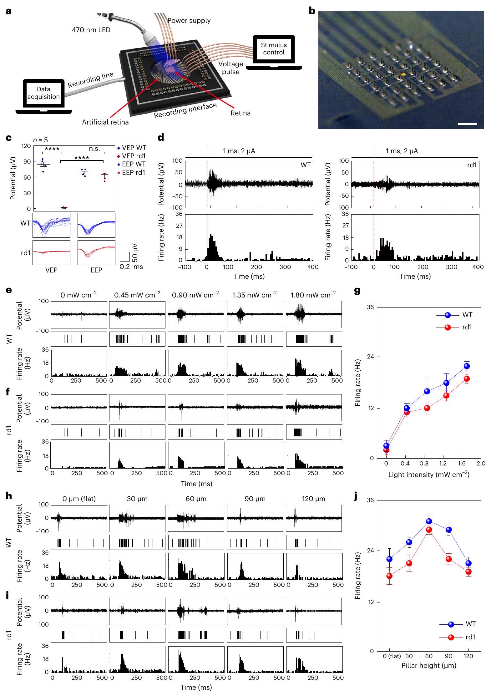
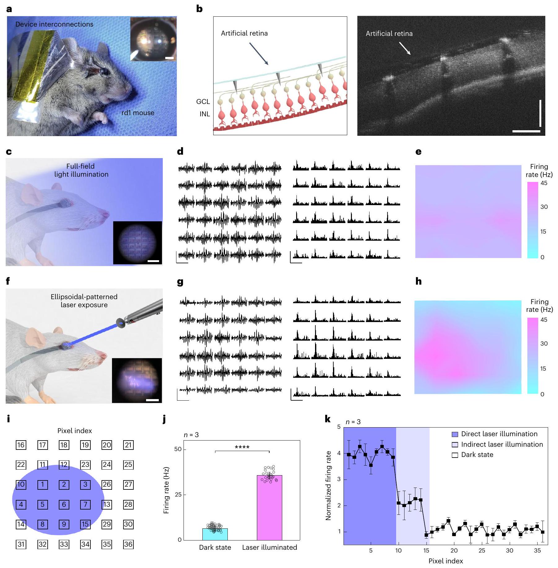
In vivo vision restoration of live rd1 mice

An artificial retina device with 3D LM microelectrodes was implanted into the live rd1 mice in vivo ( ). Before this experiment, we confirmed that the photoreceptor layer was fully degenerated (Supplementary Fig. 19). After attaching the device with external device interconnections (Supplementary Fig. 20), either (1) full-field illumination ( 470 nm ) or ( 2 ) a continuous laser exposure ( 415 nm ) through an ellipsoidal-patterned shadow mask was applied to the eye fundus. This device was well attached to the retinal surface with no notable damage or bleeding (Fig. 5a). The cross-sectional optical coherence tomography image obtained after this surgery indicates that the 3D LM microelectrodes were conformally surrounded by retinal tissues without their collapse (Fig. 5b). We further investigated the collapse of 3D LM microelectrodes post-implantation, by measuring the pillars’ tilted angle from optical coherence tomography images after implanting 180 electrodes in total into the rd1 mice retina ( ), and validated that the implanted electrodes did not collapse (Supplementary Fig. 21).
The EEPs were recorded by projecting visible light onto its retina after implanting the artificial retina (Fig. 5c and Extended Data Fig. 4). Real-time traces of potentials and firing rates of the evoked spikes under constant light illumination were recorded, and the firing rates were spatially mapped during this illumination (Fig.5d,e). The recorded
responses showed consistent potential magnitudes and firing rates of evoked spikes compared with the case involving no light illumination (Supplementary Figs. 22 and 23), indicating good uniformity across the stimulated retinal area using the device.
One of the key challenges to develop artificial vision restoration is object recognition. We demonstrated the responses from the degenerative retina, by selectively exposing the localized areas using a laser through an ellipsoidal-patterned shadow mask (Fig. 5f). The
Fig. 4 | Signal classification using unsupervised machine learning. a, Primarily classified evoked RGC spikes from hierarchical clustering. The black lines represent the points and , which provide the criteria for secondary clustering. b, Classified datasets from -means clustering. c, Entire data of evoked RGC spikes classified as cluster 1 , sorted on the basis of their magnitude and shape (left), as well as their mean RGC spikes of cluster 1 (right). Data are mean s.d. with biologically independent mice. d, Entire data of the evoked RGC spikes

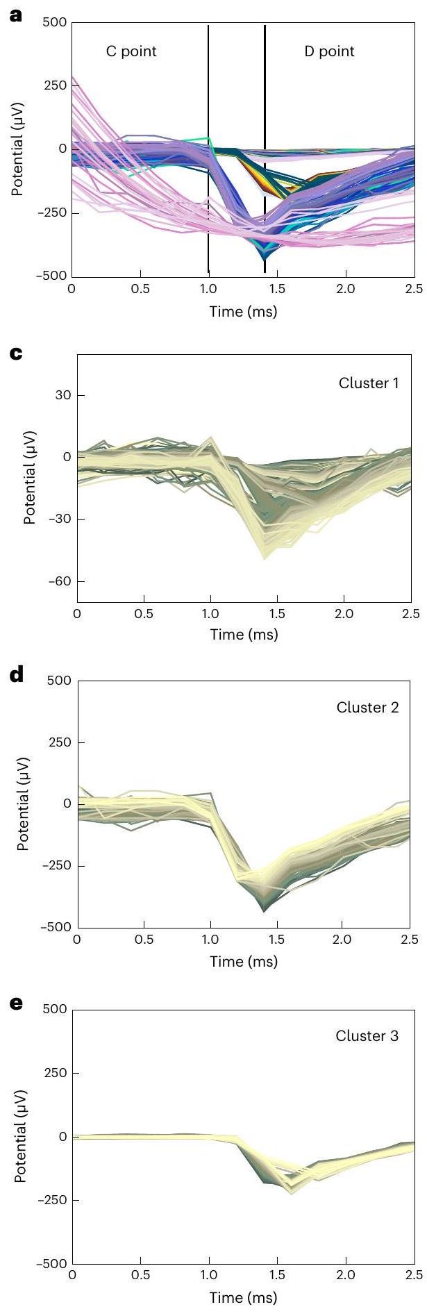
classified as cluster 2, sorted on the basis of their magnitude and shape (left), and their mean RGC spikes of cluster 2 (right). Data are mean s.d. with biologically independent mice.e, Entire data of the evoked RGC spikes classified as cluster 3, sorted on the basis of their magnitude and shape (left), as well as their mean RGC spikes of cluster 3 (right). Data are mean s.d. with biologically independent mice.
light-illuminated local area exhibited relatively larger retinal responses, compared with the area in the dark state (Fig.5g). When the RGC axons are electrically stimulated, the antidromic propagation of electrical stimuli can occur, leading to the misguided RGC response in the dark
state. However, the spatial distribution on the maximum firing rates (that is, the receptive field) was very similar to the ellipsoidal shape of this illumination (Fig. 5h). Also, the sorted RGC spikes (Supplementary Fig. 24) show a typical waveform of the somatic RGC response similar
Fig. 5| In vivo experiment using live rd1 mice for vision restoration. a,
Photograph of the in vivo experimental setup using the live rd1 mouse. The inset shows the fundus image of a live rd1 mouse with device implantation. Scale bar, , Schematic (left) and optical coherence tomography image (right) of the retina of the rd1 mouse after device implantation. Scale bars, . c, Schematic of the in vivo experiment under full-field blue-light illumination (wavelength, 470 nm ; intensity, ). The inset shows the fundus image of a live rd1 mouse with the implanted device under full-field blue-light illumination. The distorted image is due to light refraction from the artificial vitreous body. Scale bar, . d, Spike train and firing rate of the evoked RGC spikes during device operation under constant full-field blue-light illumination. Scale bars, 200 ms (horizontal); (left, vertical); 40 Hz (right, vertical). e, Contour plot of firing rates of the evoked RGC spikes under full-field blue-light illumination.f, Schematic of the in vivo animal experiment under continuous
laser exposure (wavelength, 415 nm ; intensity, ) through an ellipsoidal-patterned shadow mask. The inset shows the fundus image of a live rd1 mouse with the implanted device under continuous laser exposure through an ellipsoidal-patterned shadow mask. Scale bar, , Spike train and firing rate of the evoked RGC spikes during device operation under continuous laser exposure through an ellipsoidal-patterned shadow mask. Scale bars, 200 ms (horizontal); (left, vertical); 40 Hz (right, vertical). h, Contour plot of firing rates of the evoked RGC spikes under the illumination of patterned laser. , Index of pixels of the artificial retina. The coloured ellipsoid indicates the local illumination spot of a laser.j , Firing rates of all the pixels for the laser-illuminated and laser-unilluminated state ( ). The error bars denote s.d. Significance was calculated using an unpaired one-tailed -test: (****). k, Normalized firing rate with three different laser illumination states in every pixel. Data are mean s.d. with biologically independent mice.
to the ex vivo results (Fig. 4). To quantitatively compare the retinal responses in the laser-illuminated and laser-unilluminated area (that is, the dark state), the position of each recording electrode (pixel) was marked as an index (Fig. 5i). Then, the maximum firing rates recorded from the fully illuminated pixels (indexes 1-9) and the dark-state pixels (indexes 16-36) were averaged. The RGC activity in the fully exposed areas was approximately fourfold higher than the background RGC activity.

Conclusions

We have reported a soft artificial retina consisting of high-resolution, flexible phototransistor arrays with directly printed 3D LM microelectrodes capable of minimally invasive retinal stimulation. In vivo experiments demonstrated that the visible-light illumination induced spiking activities in the RGCs of the local retina area where the light was incident, suggesting the potential for vision restoration in live rd1 mice. These results can have a prognostic meaning in the development of personalized artificial retinas for patients with uneven retinal degeneration.
Although the device used in the in vivo experiment was limited to 36 pixels due to the small mouse eye (diameter, 3 mm ), further enlargements in device size and an increase in the number of pixels will enable its application to a large animal model with larger eyeballs and thicker retinas. In addition, our printing system was able to scale down the diameter of the 3D LM microelectrodes to . A high-resolution device with 3D LM microelectrodes, which theoretically corresponds to vision, can be fabricated (Extended Data Fig. 5) . Reducing the stimulation electrode size is crucial for achieving high-resolution stimulation. However, as the size of the stimulation site decreases, impedance increases, which limits effective stimulation. Further studies on nanoscale materials (for example, Pt nanoclusters), which enhance the stimulation efficacy by adding nanometre-scale roughness to the electrode surface, can be interesting future work for achieving higher visual acuity.

Online content

Any methods, additional references, Nature Portfolio reporting summaries, source data, extended data, supplementary information, acknowledgements, peer review information; details of author contributions and competing interests; and statements of data and code availability are available at https://doi.org/10.1038/s41565-023-01587-w.

References

  1. He, S., Dong, W., Deng, Q., Weng, S. & Sun, W. Seeing more clearly: recent advances in understanding retinal circuitry. Science 302, 408-411 (2003).
  2. Bloch, E., Luo, Y. & da Cruz, L. Advances in retinal prosthesis systems. Ther. Adv. Ophthalmol. 11, 2515841418817501 (2019).
  3. Lee, G. J., Choi, C., Kim, D.-H. & Song, Y. M. Bioinspired artificial eyes: optic components, digital cameras, and visual prostheses. Adv. Funct. Mater. 28, 1705202 (2018).
  4. Sahel, J.-A. et al. Partial recovery of visual function in a blind patient after optogenetic therapy. Nat. Med. 27, 1223-1229 (2021).
  5. Rao, Z. et al. Curvy, shape-adaptive imagers based on printed optoelectronic pixels with a kirigami design. Nat. Electron. 4, 513-521 (2021).
  6. Ko, H. C. et al. A hemispherical electronic eye camera based on compressible silicon optoelectronics. Nature 454, 748-753 (2008).
  7. Lorach, H. et al. Photovoltaic restoration of sight with high visual acuity. Nat. Med. 21, 476-482 (2015).
  8. Mathieson, K. et al. Photovoltaic retinal prosthesis with high pixel density. Nat. Photon. 6, 391-397 (2012).
  9. Tang, J. et al. Nanowire arrays restore vision in blind mice. Nat. Commun. 9, 786 (2018).
  10. Jang, J. et al. Implantation of electronic visual prosthesis for blindness restoration. Opt. Mater. Express 9, 3878-3894 (2019).
  11. Maya-Vetencourt, J. F. Subretinally injected semiconducting polymer nanoparticles rescue vision in a rat model of retinal dystrophy. Nat. Nanotechnol. 15, 30 (2020).
  12. Mandel, Y. et al. Cortical responses elicited by photovoltaic subretinal prostheses exhibit similarities to visually evoked potentials. Nat. Commun. 4, 1980 (2013).
  13. Sachs, H. G. & Gabel, V.-P. Retinal replacement-the development of microelectronic retinal prostheses-experience with subretinal implants and new aspects. Graefe’s Arch. Clin. Exp. Ophthalmol. 242, 717-723 (2004).
  14. Yue, L. et al. Ten-year follow-up of a blind patient chronically implanted with epiretinal prosthesis Argus I. Ophthalmology 122, 2545-2552.e1 (2015).
  15. Xie, H. et al. Monitoring cortical response and electrode-retina impedance under epiretinal stimulation in rats. IEEE Trans. Neural Syst. Rehabil. Eng. 29, 1178-1187 (2021).
  16. Lee, K.-W. et al. Pillar-shaped stimulus electrode array for high-efficiency stimulation of fully implantable epiretinal prosthesis. J. Micromech. Microeng. 22, 105015 (2012).
  17. Ahuja, A. K. et al. Factors affecting perceptual threshold in Argus II retinal prosthesis subjects. Trans. Vis. Sci. Technol. 2, 1 (2013).
  18. Ghani, N., Bansal, J., Naidu, A. & Chaudhary, K. M. Long term positional stability of the Argus II retinal prosthesis epiretinal implant. BMC Ophthalmol. 23, 70 (2023).
  19. Palanker, D., Vankov, A., Huie, P. & Baccus, S. Design of a high-resolution optoelectronic retinal prosthesis. J. Neural Eng. 2, S105-S120 (2005).
  20. Flores, T. et al. Optimization of pillar electrodes in subretinal prosthesis for enhanced proximity to target neurons. J. Neural Eng. 15, 036011 (2018).
  21. Esler, T. B. et al. Minimizing activation of overlying axons with epiretinal stimulation: the role of fiber orientation and electrode configuration. PLoS ONE 13, e0193598 (2018).
  22. Todorova, M. G., Scholl, H. P. N. & della Volpe Waizel, M. The impact of macular edema on microvascular and metabolic alterations in retinitis pigmentosa. Graefe’s Arch. Clin. Exp. Ophthalmol. 259, 643-652 (2021).
  23. Choi, C. et al. Human eye-inspired soft optoelectronic device using high-density -graphene curved image sensor array. Nat. Commun. 8, 1664 (2017).
  24. Seo, H. W. et al. A 3D flexible microelectrode array for subretinal stimulation. J. Neural Eng. 16, 056016 (2019).
  25. Cho, Y. H., Park, Y.-G., Kim, S. & Park, J.-U. 3D electrodes for bioelectronics. Adv. Mater. 33, 2005805 (2021).
  26. Ho, E. et al. Characteristics of prosthetic vision in rats with subretinal flat and pillar electrode arrays. J. Neural Eng. 16, 066027 (2019).
  27. Kim, E. et al. Fabrication of pillar shaped electrode arrays for artificial retinal implants. Sensors 8, 5845-5856 (2008).
  28. Park, Y.-G. et al. Liquid metal-based soft electronics for wearable healthcare. Adv. Healthc. Mater. 10, 2002280 (2021).
  29. Park, Y.-G. et al. Three-dimensional, high-resolution printing of carbon nanotube/liquid metal composites with mechanical and electrical reinforcement. Nano Lett. 19, 4866-4872 (2019).
  30. Yun, I. et al. Transferable transparent electrodes of liquid metals for bifacial perovskite solar cells and heaters. Nano Energy 93, 106857 (2022).
  31. Dickey, M. D. Stretchable and soft electronics using liquid metals. Adv. Mater. 29, 1606425 (2017).
  32. Park, Y.-G., An, H. S., Kim, J.-Y. & Park, J.-U. High-resolution, reconfigurable printing of liquid metals with three-dimensional structures. Sci. Adv. 5, eaaw2844 (2019).
  33. An, H. S. et al. High-resolution 3D printing of freeform, transparent displays in ambient air. Adv. Sci. 6, 1901603 (2019).
  34. Jang, J. et al. Human-interactive, active-matrix displays for visualization of tactile pressures. Adv. Mater. Technol. 4, 1900082 (2019).
  35. Kim, J. et al. Highly transparent and stretchable field-effect transistor sensors using graphene-nanowire hybrid nanostructures. Adv. Mater. 27, 3292-3297 (2015).
  36. Chen, S. et al. Toxicity and biocompatibility of liquid metals. Adv. Healthc. Mater. 12, 2201924 (2023).
  37. Yanovitch, L., Raz-Prag, D. & Hanein, Y. A new high-resolution three-dimensional retinal implant: system design and preliminary human results. Preprint at bioRxiv https://doi. org/10.1101/2022.09.14.507901 (2022).
  38. Jones, I. L., Warner, M. & Stevens, J. D. Mathematical modelling of the elastic properties of retina: a determination of Young’s modulus. Eye 6, 556-559 (1992).
  39. Shin, H. et al. Recent progress on wearable point-of-care devices for ocular systems. Lab Chip 21, 1269-1286 (2021).
  40. Mahadevappa, M. et al. Perceptual thresholds and electrode impedance in three retinal prosthesis subjects. IEEE Trans. Neural Syst. Rehabil. Eng. 13, 201-206 (2005).
  41. ISO 10993-5:2009. Biological Evaluation of Medical Devices. Part 5: Tests for In Vitro Cytotoxicity (International Organization for Standardization, 2009).
  42. Jacobs, G. H., Williams, G. A., Cahill, H. & Nathans, J. Emergence of novel color vision in mice engineered to express a human cone photopigment. Science 315, 1723-1725 (2007).
  43. Abballe, L. & Asari, H. Natural image statistics for mouse vision. PLoS ONE 17, e0262763 (2022).
  44. O’Hearn, T. M. et al. Electrical stimulation in normal and retinal degeneration (rd1) isolated mouse retina. Vis. Res. 46, 3198-3204 (2006).
  45. Saboo, K. V. et al. Unsupervised machine-learning classification of electrophysiologically active electrodes during human cognitive task performance. Sci. Rep. 9, 17390 (2019).
  46. Nielsen, F. Introduction to HPC with MPI for Data Science (Springer International Publishing, 2016).
  47. Hartigan, J. A. Clustering Algorithms (Wiley, 1975).
  48. Rousseeuw, P. & Rousseeuw, P. J. Silhouettes: a graphical aid to the interpretation and validation of cluster analysis. J. Comput. Appl. Math. 20, 53-65 (1987).
  49. Bholowalia, P. & Kumar, A. EBK-means: a clustering technique based on elbow method and K-means in WSN. Int. J. Comput. Appl. 105, 17-24 (2014).
  50. Li, P. H. et al. Anatomical identification of extracellularly recorded cells in large-scale multielectrode recordings. J. Neurosci. 35, 4663-4675 (2015).
Publisher’s note Springer Nature remains neutral with regard to jurisdictional claims in published maps and institutional affiliations.
Open Access This article is licensed under a Creative Commons Attribution 4.0 International License, which permits use, sharing, adaptation, distribution and reproduction in any medium or format, as long as you give appropriate credit to the original author(s) and the source, provide a link to the Creative Commons license, and indicate if changes were made. The images or other third party material in this article are included in the article’s Creative Commons license, unless indicated otherwise in a credit line to the material. If material is not included in the article’s Creative Commons license and your intended use is not permitted by statutory regulation or exceeds the permitted use, you will need to obtain permission directly from the copyright holder. To view a copy of this license, visit http://creativecommons. org/licenses/by/4.0/.
© The Author(s) 2024

Methods

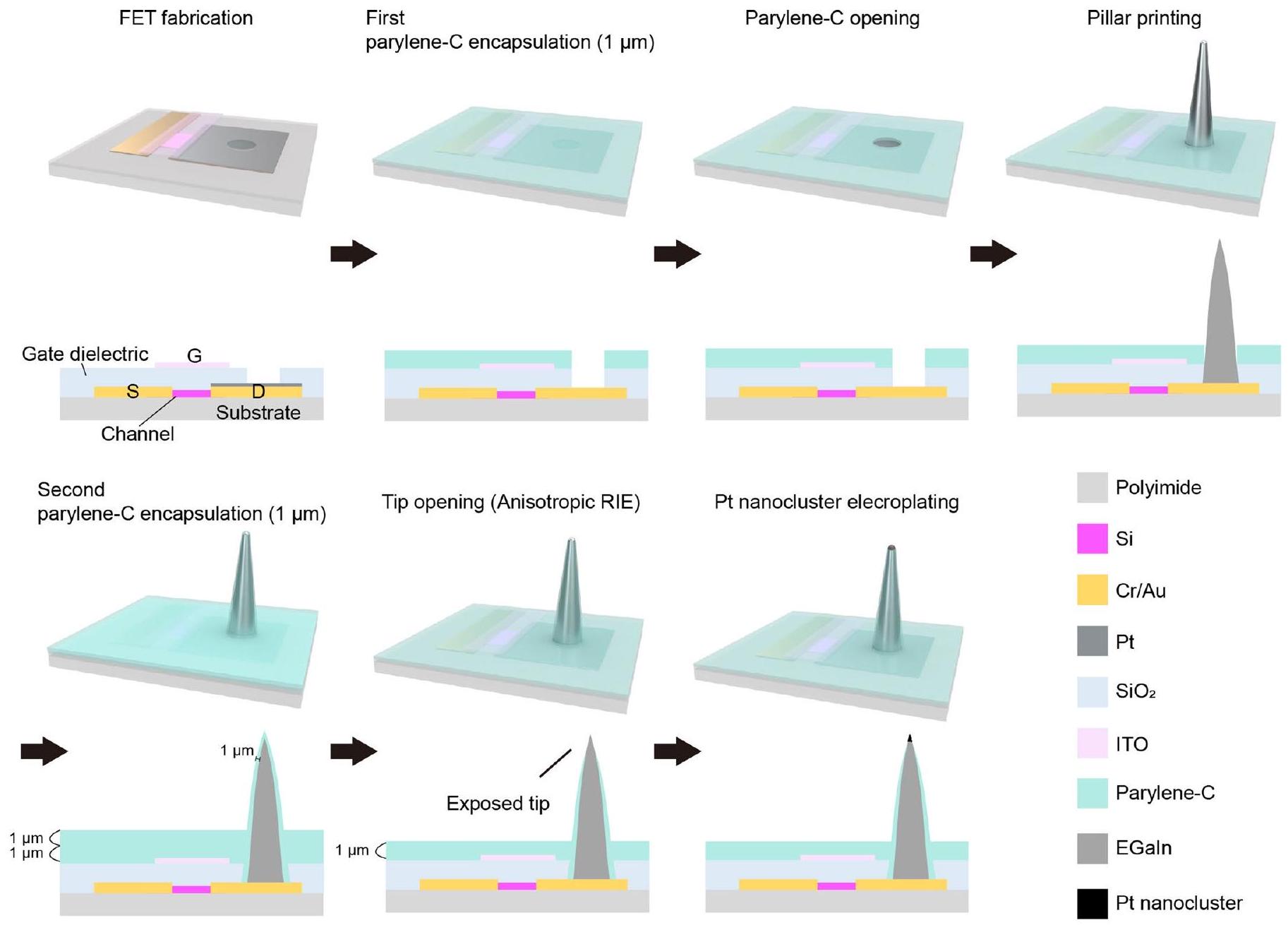
Fabrication of phototransistor arrays for the artificial retina

The device consists of Si channels ( 340 nm ), ( 30 nm ) source (S)/drain (D)/interconnect electrodes, dielectric layer ( 500 nm ) and indium tin oxide gate ( G ) electrode ( 150 nm ). The Si channel, which is a representative photoabsorbing semiconductor, was chosen as a proof of concept, but it can be easily replaced by other alternatives with higher sensitivity and flexibility (that is, two-dimensional materials) to further enhance the optoelectronic performance of artificial retinas. For the fabrication of these phototransistor arrays, first, an array of single-crystalline Si , which serves as the channel of the transistor, was photolithographically patterned using a positive photoresist (S1818, MicroChem) on a silicon-on-insulator wafer ( 340 nm boron-doped p-type Si with a resistivity of on 400 nm buried oxide; Soitec). This transistor array was fabricated on a thin and transparent polyimide film (thickness, ). The Si channels were etched with an RIE system with sulfur hexafluoride ( ) plasma ( s.c.c.m./Ar 55 s.c.c.m.; ), completing the channel isolation process. Any subsequently remaining photoresist residue was removed using a piranha solution ( 10 min ). To separate the Si channel from the silicon-on-insulator wafer, the buried oxide layer was etched in a hydrogen fluoride solution for 18 min . Second, the pattern of Si channels was transferred from a silicon-on-insulator wafer onto the flexible and transparent polyimide film ( ) using a polydimethylsiloxane stamp (SYLGARD 184, 10:1 weight ratio of base and curing agent). Cr were deposited using an electron-beam evaporator and were photolithographically patterned to form a source (S) electrode, a drain (D) electrode and interconnects . Then, a sacrificial layer (LOR 3A photoresist, Kayaku) was spun on the substrate and photolithographically patterned, and this was followed by the deposition of -thick Pt on the opened area with an electron-beam evaporator. This metal layer was deposited to prevent the penetration of gallium atoms to the Au drain electrodes. Subsequently, silicon dioxide ( ) was deposited with a thickness of 500 nm at using plasma-enhanced chemical vapour deposition, and it was photolithographically patterned as a dielectric layer. Then, for the patterning of the gate (G) electrode, a sacrificial layer (LOR3A photoresist, Kayaku) was spun on the substrate and photolithographically patterned. Indium tin oxide was deposited as a gate electrode with a thickness of 150 nm at room temperature by radio-frequency magnetron sputtering, and it was immersed in mr-Rem 700 (lift-off solution, micro resist technology) at for 30 min to melt the sacrificial layer. As a biocompatible encapsulation layer, a -thick layer of parylene C was deposited and photolithographically patterned by dry etching with RIE ( s.c.c.m., ) to open the area for the direct printing of 3D LM microelectrodes.

Fabrication of 3D LM microelectrodes

The key steps in the fabrication of the 3D LM microelectrodes are as follows:
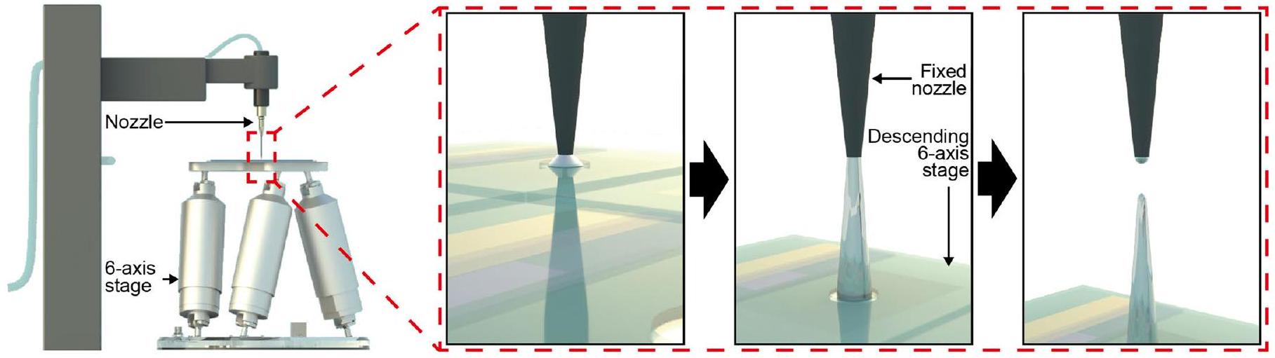
(1) Direct printing of 3D pristine EGaln electrodes: the direct printing system consists of a capillary nozzle connected to an ink reservoir; a pneumatic pressure controller and a six-axis stage with automatic movements in the and axes; two tilting axes in the and axes; and rotation in the plane. First, a pipette puller (P-1000, Sutter Instrument) was used to make a glass capillary (Sutter Instrument) as a nozzle with inner diameters of 5 to . Then, a nozzle was mounted onto a syringe-type reservoir, and a substrate was placed on the six-axis stage. All of the LM printing steps were recorded by the microscope camera (QImaging MicroPublisher 5.0 with real-time viewing, Teledyne Photometrics) to control the nozzle from the substrate using the six-axis stage (H-820 6-Axis Hexapod, Physik Instrumente) during the printing process. The distance between the tip of the nozzle and the substrate was controlled to be in the range of according to the diameter of the nozzle, and the pneumatic pressure ( )
was applied to deliver the EGaIn ink (75.5% gallium and 24.5% indium alloy by weight; Changsha Santech Materials) from a reservoir onto the substrate through the nozzle. After we controlled the axis of the six-axis stage to make contact between EGaln and the opened area of the drain electrode, the ink was directly printed in a circular shape on the top surface of the drain to exhibit a thicker base of the 3D micropillar for its structural stability. By adjusting the printing motion along the axis at a velocity in the range of 1 to , the 3D pillar of EGaln with a uniform diameter (except the circular base part) can be printed (Supplementary Video 1). On exposure to air, EGaln instantaneously forms a thin solid layer ( ) of gallium oxide on its surface under atmospheric oxygen levels to maintain its vertical 3D structure of EGaln. This oxide skin is thin enough to avoid substantially damaging the cellular interfaces, and it is solid enough to maintain its 3D shape against gravity and surface tension.
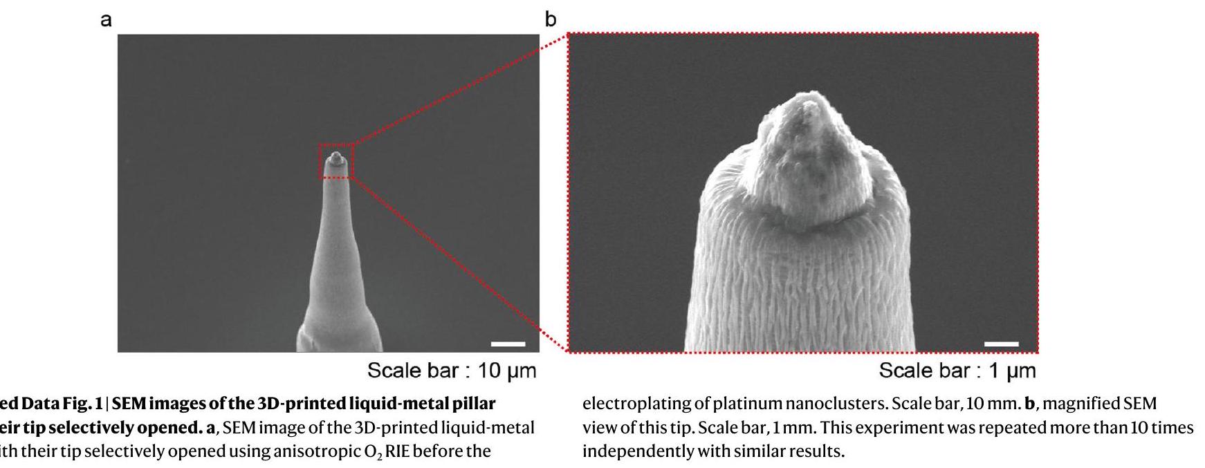
(2) Selective opening of 3D electrode tips: after the printing of the 3D pristine EGaln electrodes, additional parylene C (thickness, ) was deposited on the entire device, including the 3D electrodes for the passivation of their sidewalls. Only their tips were selectively opened using anisotropic RIE ( ), as the additional parylene C encapsulating layer served as a protective layer of the first parylene encapsulation layer as well as the encapsulation layer of the sidewalls of the 3D micropillars.
(3) Deposition of Pt nanoclusters: to prepare 50 ml of an electroplating solution, we mixed 50 ml of deionized water, 10 mg of lead acetate trihydrate (Sigma-Aldrich) and 0.5 g of platinum tetrachloride (Sigma-Aldrich) at room temperature. This electroplating solution was stirred for 20 min by ultrasonic vibration. The electroplating was performed by ion transfer between the cathode and anode in the Pt electroplating solution. After mounting the device to a multichannel recording interface (MZ-60, Tucker-Davis Technologies), a cathode (the 3D pristine EGaIn microelectrode that is to be electroplated) and an anode ( Pt electrode) were immersed in this electroplating solution, and each electrode was connected to a source meter (Keithley 2400, Tektronix). An electrical current of 0.1 mA was applied for 60 s to generate the electroplating reaction (Supplementary Fig. 25). Due to potential variations in currents under light exposure, we performed the electroplating of Pt nanoclusters in the dark state.
(3) Rinsing process of the artificial retina: before the implantation of the device, we rinsed the artificial retina by gently immersing the device in ethanol solution ( 15 min ) and deionized water ( 15 min ) followed by ultraviolet exposure ( 30 min ).

Ex vivo animal experiments

Exvivo experiments were conducted based on the guidelines and were approved by the Institute of Animal Care and Use Committee of Yonsei University (IACUC-A-201911-985-01, IACUC-202011-1164-05, Yonsei IACUC). The recording involved the retinas of five mice for both WT and rd1 type, and for the recording of retinal responses (that is, visually or electrically evoked retinal spike potentials and firing rate of the spikes); each recording electrode was positioned adjacent to each stimulation electrode (pitch between the stimulating and recording electrodes, ). The retinas of both WT mice (C57BL/6J, Japan SLC) and rd1 mice (C3H/HeJ, Japan SLC) were explanted, and small pieces ( ) were isolated and transferred to the artificial retina with the phosphate-buffered saline medium by RGCs facing the device, and a heating pad was used to maintain the temperature of the retinas at . The animal was immediately sacrificed after extraction. The isolated retinas from WT and rd1 mice were directly placed on our device (consisting of 36 stimulating and recording electrode pairs), and our 3D electrodes were directed towards the RGC side of the retina in phosphate-buffered saline media. Immediately before implanting this device into the retina, the device sample was instantly frozen to turn the liquid-phase EGaln into a solid by leaving it in cold storage (below the
melting point of EGaln, ). Then, the protrudent pillar shape of the 3D electrodes returned to a liquid phase and did not collapse even after being implanted into the retina.
Since mice are dichromatic mammals having only two cone types (blue and green light sensitive) , the blue light (wavelength, 470 nm ) was used for exposure in this experiment. For electrical stimulation, the transistor of our device was operated with a specific condition ( , d.c. bias of 5 V ; : pulsed bias of 1 V with a duration of 1 ms and frequency of 10 Hz ) and the recordings were performed with the adjacent recording electrodes. Electrophysiological recordings of the retina were conducted by multielectrode array recording and multichannel stimulation (PZ5 and Subject Interface, Tucker-Davis Technologies) and a data processor with a real-time controller (RZ2 BioAmp Processor, Tucker-Davis Technologies). We recorded the VEP and EEP signals at a 25 kHz sampling rate using a 300 Hz low-pass filter and high-pass filter. The experimental data were processed further by applying a band-pass filter with MATLAB R2021a (MathWorks). No data points were excluded from the analyses.

In vivo implantation

The rd1 mice ( ) were anaesthetized with an intraperitoneal injection of a mixture of tiletamine and zolazepam ( body weight) and xylazine hydrochloride ( body weight). The pupils of the mice were dilated with eye drops that contained phenylephrine and tropicamide. The body temperatures of the mice were maintained at with a heating pad.
For the surgical procedures, the mouse was placed in a head holder to maintain the head in a fixed position and to allow access to the eye. The head holder was placed under an optical microscope with an illuminator. A clear 2.2 mm corneal knife (KAI MEDICAL; CCR-22AGF) was used to make a 1.5 mm incision in the area of the pars plana. Immediately before implanting this device into the retina, the device sample was instantly frozen to turn the liquid-phase EGaln into a solid by leaving it in cold storage (below the melting point of EGaln, that is, ). Then, it was implanted into the vitreous cavity (that is, attached to the retinal surfaces) via the incision that was made earlier. For preventing cataracts during a continuous functional analysis, a 10 g drop of hypromellose (Hycell oph soln) was applied to the surface of the cornea. During this in vivo experiment, a hydrogel-based artificial vitreous body was initially filled in the vitreous cavity of the mouse eye to prevent undesired side effects, such as hypotony (low intraocular pressure). After the experiment, the mice were immediately euthanized by carbon dioxide inhalation in a carbon dioxide chamber. No statistical methods were used to predetermine the sample sizes, but our sample sizes are similar to those reported in previous publications .

In vivo animal experiments

In vivo experiments were conducted based on the guidelines of the Institute of Animal Care and Use Committee of Yonsei University (IACUC-A-202205-1478-01, Yonsei IACUC). Considering the size of the eyeball of a mouse (diameter, ), we fabricated an artificial retina integrated with arrays of phototransistors (pixel pitch, ; device width, 2 mm ) with 3D LM microelectrodes (height, ; diameter, ). This artificial retina was implanted into the innermost retinal surface of the rd1 mouse epiretinal, with external device interconnections. All the devices and animals tested were randomly selected. The recording lines were connected to the glass pad with interconnect electrodes and then patterned with photolithography and wet etching after the deposition of by an electron-beam evaporator. The interconnect pad was inserted into the multielectrode array recorder with a multichannel stimulator (PZ5 and Subject Interface, Tucker-Davis Technologies) and a data processor with a real-time controller (RZ2 BioAmp Processor, Tucker-Davis Technologies). The multichannel experimental data of
the spike signal and firing rate were obtained and exported by analysis software (Synapse Suite version 94, Tucker-Davis Technologies). Then, the data were processed and mapped with MATLAB R2021a (MathWorks) and Origin 2022b software. Full-field light illumination ( 470 nm , TouchBright T1 with BN470 band-pass filter, Live Cell Instrument) or a laser (wavelength, 415 nm ) through an ellipsoidal pattern of a shadow mask was applied to the fundus of the mouse’s eye for light exposure (duration, 5 s ). No data points were excluded from the analyses. Also, data met the assumptions of the statistical tests used.

Statistical analysis

All data were presented as mean standard deviation (s.d.). Statistical calculations of value were performed using an open-source code of MATLAB R2021a. Significance was calculated using an unpaired one-tailed -test.

Reporting summary

Further information on research design is available in the Nature Portfolio Reporting Summary linked to this article.

Data availability

The data regarding the characterization of the artificial retina and animal experiments are available via Figshare at https://doi.org/10.6084/ m9.figshare.22815461. Statistical source data are provided with this paper. The raw datasets generated during this study are available from the corresponding authors upon reasonable request. Source data are provided with this paper.

Code availability

The custom codes for MATLAB used in this study are available from the corresponding authors upon reasonable request.

Acknowledgements

This work was supported by the Ministry of Science & ICT (MSIT), the Ministry of Trade, Industry and Energy (MOTIE), the Ministry of Health & Welfare and the Ministry of Food and Drug Safety of Korea through the National Research Foundation (2019R1A2C2086729 and 2023R1A2C2006257); Nano Material Technology Development Program (2021M3D1A2049914); ERC Program (2022R1A5A6000846 and 2020R1A5A1019131); the Technology Innovation Program (20013621, Center for Super Critical Material Industrial Technology); and the Korea Medical Device Development Fund grant (RMS 2022-11-1209/KMDF RS-202200141392). We also thank financial support from the Institute for Basic Science (IBS-RO26-D1).

Author contributions

W.G.C., J.J., G.C. and S.L. conducted the experiments, analysed the data and wrote the paper. W.G.C., J.J., S.L. and H.S. fabricated the phototransistor arrays and measured the optoelectronic properties of the device. H.J. conducted the cell viability test. G.C. and J.L. conducted the animal surgery. H.K. and S.G.L. performed the signal classification using machine learning. S.K. and E.K. performed the printing of the 3D LM. S.H.B. oversaw the animal experiments and revised the paper. J.-U.P. oversaw all of the research phases and revised the paper. All of the authors discussed and commented on the paper.

Competing interests

The authors declare no competing interests

Additional information

Extended data is available for this paper at
https://doi.org/10.1038/s41565-023-01587-w.
Supplementary information The online version contains supplementary material available at https://doi.org/10.1038/s41565-023-01587-w.
Correspondence and requests for materials should be addressed to Seung Geol Lee, Suk Ho Byeon or Jang-Ung Park.
Peer review information Nature Nanotechnology thanks the anonymous reviewers for their contribution to the peer review of this work.
Reprints and permissions information is available at www.nature.com/reprints.
Extended Data Fig. 2 | The 3D-printing process of the liquid-metal pillar. Schematic illustrations of the 3D-printing process to form a liquid-metal pillar.
Extended Data Fig. 3 | Detailed fabrication process of the 3D microelectrode. Schematic illustrations of the 3D microelectrode fabrication process.
Extended Data Fig. 4 | Schematic illustrations of design of the soft artificial retina device. Schematic illustrations of , the design of our artificial retina device, , the pixel design, c, the layout and dimensions of a FET.
Extended Data Fig. 5|High-resolution artificial retina device. a, Photograph of the artificial retina where a high-resolution transistor array was integrated with 3D liquid-metal electrodes ( pixels). Scale bar, 1 mm . b, SEM image of this phototransistor array with 3D liquid microelectrodes (pixel pitch: ,
b
pillar height: , pillar diameter: ) before depositing the top parylene-C encapsulating layer. Scale bar, . This experiment was repeated 2 times independently with similar results.

natureportfolio

Corresponding author(s): Jang-Ung Park
Last updated by author(s): Nov 22, 2023

Reporting Summary

Nature Portfolio wishes to improve the reproducibility of the work that we publish. This form provides structure for consistency and transparency in reporting. For further information on Nature Portfolio policies, see our Editorial Policies and the Editorial Policy Checklist.

Statistics

For all statistical analyses, confirm that the following items are present in the figure legend, table legend, main text, or Methods section.

Confirmed

The exact sample size for each experimental group/condition, given as a discrete number and unit of measurement
A statement on whether measurements were taken from distinct samples or whether the same sample was measured repeatedly
The statistical test(s) used AND whether they are one- or two-sided
Only common tests should be described solely by name; describe more complex techniques in the Methods section.
A description of all covariates tested
A description of any assumptions or corrections, such as tests of normality and adjustment for multiple comparisons
A full description of the statistical parameters including central tendency (e.g. means) or other basic estimates (e.g. regression coefficient) AND variation (e.g. standard deviation) or associated estimates of uncertainty (e.g. confidence intervals)
For null hypothesis testing, the test statistic (e.g. ) with confidence intervals, effect sizes, degrees of freedom and value noted Give values as exact values whenever suitable.
For Bayesian analysis, information on the choice of priors and Markov chain Monte Carlo settings
For hierarchical and complex designs, identification of the appropriate level for tests and full reporting of outcomes
Estimates of effect sizes (e.g. Cohen’s , Pearson’s ), indicating how they were calculated
Our web collection on statistics for biologists contains articles on many of the points above.

Software and code

Policy information about availability of computer code

Data collection

Electrophysiological recordings of the retina : Multi-electrode array recording and a data processor with a real-time controller (RZZ BioAmp Processor, Tucker-Davis Technologies, USA)
Microsoft Excel 2022

Data analysis

Bandpass filtering and spike detection was made by a custom code with MATLAB R2021a (MathWorks)
Origin Pro 2022b (Origin Lab)
For manuscripts utilizing custom algorithms or software that are central to the research but not yet described in published literature, software must be made available to editors and reviewers. We strongly encourage code deposition in a community repository (e.g. GitHub). See the Nature Portfolio guidelines for submitting code & software for further information.

Policy information about availability of data

All manuscripts must include a data availability statement. This statement should provide the following information, where applicable:
  • Accession codes, unique identifiers, or web links for publicly available datasets
  • A description of any restrictions on data availability
  • For clinical datasets or third party data, please ensure that the statement adheres to our policy
Figshare dataset link: https://doi.org/10.6084/m9.figshare. 22815461
The custom codes for MATLAB used in this study and the access to our raw data are available from the corresponding authors upon reasonable request.

Human research participants

Policy information about studies involving human research participants and Sex and Gender in Research.
Reporting on sex and gender Use the terms sex (biological attribute) and gender (shaped by social and cultural circumstances) carefully in order to avoid confusing both terms. Indicate if findings apply to only one sex or gender; describe whether sex and gender were considered in study design whether sex and/or gender was determined based on self-reporting or assigned and methods used. Provide in the source data disaggregated sex and gender data where this information has been collected, and consent has been obtained for sharing of individual-level data; provide overall numbers in this Reporting Summary. Please state if this information has not been collected. Report sex- and gender-based analyses where performed, justify reasons for lack of sex- and gender-based analysis.
Population characteristics Describe the covariate-relevant population characteristics of the human research participants (e.g. age, genotypic information, past and current diagnosis and treatment categories). If you filled out the behavioural & social sciences study design questions and have nothing to add here, write “See above.”
Recruitment Describe how participants were recruited. Outline any potential self-selection bias or other biases that may be present and how these are likely to impact results.
Ethics oversight Identify the organization(s) that approved the study protocol.
Note that full information on the approval of the study protocol must also be provided in the manuscript.

Field-specific reporting

Please select the one below that is the best fit for your research. If you are not sure, read the appropriate sections before making your selection.
Life sciences Behavioural & social sciences Ecological, evolutionary & environmental sciences
For a reference copy of the document with all sections, see nature.com/documents/nr-reporting-summary-flat.pdf

Life sciences study design

All studies must disclose on these points even when the disclosure is negative.
Sample size The number of animals were chosen enough to perform statistical analysis.
Data exclusions
No data were excluded from the analyses
Replication
Replication of the device was successful.
Randomization
The number of animals were allocated enough to perform statistical analysis as well as the devices.
Blinding
NA

Reporting for specific materials, systems and methods

We require information from authors about some types of materials, experimental systems and methods used in many studies. Here, indicate whether each material, system or method listed is relevant to your study. If you are not sure if a list item applies to your research, read the appropriate section before selecting a response.
Materials & experimental systems Methods
n/a Involved in the study n/a Involved in the study
X Antibodies
ChIP-seq
Eukaryotic cell lines
Flow cytometry
Palaeontology and archaeology
Dual use research of concern

Antibodies

Antibodies used
The antibodies used in this study were as follows:
anti-CD68 (Cell Signaling Technology, 97778S, 1:500 dilution)
anti-CD11b (Abcam, ab62817, 1:500 dilution)
anti-SNCG (Abnova, H00006623-M10A, 1:500 dilution)
Donkey anti-Mouse IgG (H+L) Highly Cross-Adsorbed Secondary Antibody, Alexa Fluor (Invitrogen, A21203, 1:1000 dilution)
Donkey anti-Rabbit IgG (H+L) Highly Cross-Adsorbed Secondary Antibody, Alexa Fluor (Invitrogen, A21206, 1:1000 dilution)
Donkey anti-Goat IgG (H+L) Highly Cross-Adsorbed Secondary Antibody, Alexa Fluor™ Plus 405 (Invitrogen, A48259, 1:1000 dilution)
Rabbit anti-Goat IgG (H+L), Superclonal Recombinant Secondary Antibody, Alexa Fluor (Invitrogen, A27016, 1:1000 dilution)
Validation
All antibodies used in this study were obtained from the indicated commercial vendors, and the validations of each antibody are provided by the vendor on the products’ webpage:
anti-CD68: https://www.cellsignal.com/products/primary-antibodies/cd68-e3o7v-rabbit-mab/97778
anti-CD11b: https://www.abcam.com/products/primary-antibodies/cd11b-antibody-ab62817.html
anti-SNCG: https://www.abnova.com/en-global/product/detail/H00006623-M01A
Donkey anti-Mouse IgG (H+L) Highly Cross-Adsorbed Secondary Antibody, Alexa Fluor 594: https://www.thermofisher.com/ antibody/product/Donkey-anti-Mouse-IgG-H-L-Highly-Cross-Adsorbed-Secondary-Antibody-Polyclonal/A-21203
Donkey anti-Rabbit IgG (H+L) Highly Cross-Adsorbed Secondary Antibody, Alexa Fluor 488: https://www.thermofisher.com/ antibody/product/Donkey-anti-Rabbit-IgG-H-L-Highly-Cross-Adsorbed-Secondary-Antibody-Polyclonal/A-21206
Donkey anti-Goat IgG (H+L) Highly Cross-Adsorbed Secondary Antibody, Alexa Fluor Plus 405: https://www.thermofisher.com/ antibody/product/Donkey-anti-Goat-IgG-H-L-Highly-Cross-Adsorbed-Secondary-Antibody-Polyclonal/A48259
Rabbit anti-Goat IgG (H+L), Superclonal Recombinant Secondary Antibody, Alexa Fluor 594: https://www.thermofisher.com/ antibody/product/Rabbit-anti-Goat-IgG-H-L-Secondary-Antibody-Recombinant-Polyclonal/A27016

Eukaryotic cell lines

Policy information about cell lines and Sex and Gender in Research

Cell line source(s)
Authentication
Mycoplasma contamination
Commonly misidentified lines (See ICLAC register)
ARPE-19 was obtained from ATCC.
The authentication of cell lines performed by ATCC can be found at https://www.atcc.org/api/pdf/product-sheet? id=CRL-2302.
All cell lines tested negative for mycoplasma.
No commonly misidentified cell lines were used.

Animals and other research organisms

Policy information about studies involving animals; ARRIVE guidelines recommended for reporting animal research, and Sex and Gender in Research
Laboratory animals Wild-type mice : Male, C57BL/6J, 8-weeks old; Rd1 mice : Male, C3H, 8-weeks old
Wild animals n/a
Reporting on sex
This study involved only male for both wild-type and rd1 mice to exclude sex-related variations.
Field-collected samples
n/a
Ethics oversight All of the experimental procedures performed on the animals were conducted based on the guidelines and were approved by the Institute of Animal Care and Use Committee of Yonsei University.

Flow Cytometry

Plots

Confirm that:
The axis labels state the marker and fluorochrome used (e.g. CD4-FITC).
The axis scales are clearly visible. Include numbers along axes only for bottom left plot of group (a ‘group’ is an analysis of identical markers).
All plots are contour plots with outliers or pseudocolor plots.
A numerical value for number of cells or percentage (with statistics) is provided.

Methodology

Sample preparation

The artificial retina device and PI film were each cut into pieces and attached to a 96-well cell culture plate. human retinal pigmented epithelium cells (Human ARPE19 cells) seeded with 3,000 on the reference, negative control (PI film), positive control (puromycin-treated cells), and artificial retina and cultured at for 7 days. The positive control was treated with puromycin at a concentration of . To harvest cultured cells on artificial retinal devices and PI films, the devices and films were detached with forceps, transferred to 1.5 ml tubes, and treated with trypsin/EDTA The reference and puromycin-treated positive controls were harvested by treating the cells on the plates with . Harvested cells were double stained using the Annexin V conjugated with fluorescein isothiocyanate (FITC) and propidium iodide in the kit (Annexin V-FITC Apoptosis Detection kit, Sigma-Aldrich) for 10 minutes in the dark at room temperature.
Instrument
Flow cytometry analysis was performed by using BD FACS Verse II (Becton Dickinson and company)
Software
Data were acquired in BD FACSuite software and analysed in FlowJo software.
Cell population abundance
For analysis, 10,000 cells were recorded from each sample.
Gating strategy
Cells were first gated to exclude debris (using FSC-A vs SSC-A), then gated for singlet (using FSC-H vs FSC-W and SSC-H vs SSCW, sequentially). Gating was set up to use reference and positive control (puromycin-treated cells) (PI negative vs PI positive and FITC negative vs FITC positive, respectively).
Tick this box to confirm that a figure exemplifying the gating strategy is provided in the Supplementary Information.

  1. A full list of affiliations appears at the end of the paper. e-mail: seunggeol.lee@pusan.ac.kr; shbyeon@yuhs.ac; jang-ung@yonsei.ac.kr
  2. f, EEPs of rd1 mouse retina under light ( 470 nm ) exposure with different intensities during the operation of the artificial retina with flat-surface-type stimulation electrodes.g, Firing rates of EEPs as a function of illuminated light intensities for WT and rd1 mouse retina. Data are mean s.d. with biologically independent mice. , EEPs of WT mouse retina under light ( 470 nm ) exposure during the operation of artificial retina with different heights of the 3D LM microelectrode. i, EEPs of rd1 mouse retina under light ( 470 nm ) exposure during the operation of the artificial retina with different heights of the 3D LM microelectrode. j, Firing rates of evoked RGC spikes as a function of heights of 3D LM microelectrodes for WT and rd1 mouse retina. Data are mean s.d. with biologically independent mice.
  3. Department of Materials Science & Engineering, Yonsei University, Seoul, Republic of Korea. Center for Nanomedicine, Institute for Basic Science (IBS), Seoul, Republic of Korea. Graduate Program of Nano Biomedical Engineering (NanoBME), Advanced Science Institute, Yonsei University, Seoul, Republic of Korea. Institute of Vision Research, Department of Ophthalmology, Severance Eye Hospital, Yonsei University College of Medicine, Seoul, Republic of Korea. Brain Korea 21 Project for Medical Science, Yonsei University College of Medicine, Seoul, Republic of Korea. School of Chemical Engineering, Pusan National University, Busan, Republic of Korea. Institute of Vision Research, Department of Ophthalmology, Gangnam Severance Hospital, Yonsei University College of Medicine, Seoul, Republic of Korea. Department of Organic Material Science and Engineering, Pusan National University, Busan, Republic of Korea. Department of Neurosurgery, Yonsei University College of Medicine, Seoul, Republic of Korea. These authors contributed equally: Won Gi Chung, Jiuk Jang, Gang Cui, Sanghoon Lee. e-mail: seunggeol.lee@pusan.ac.kr; shbyeon@yuhs.ac; jang-ung@yonsei.ac.kr
  4. Note that full information on the approval of the study protocol must also be provided in the manuscript.