مذبذب ميكروويف منخفض الضوضاء قائم على رقاقة ضوئية Photonic chip-based low-noise microwave oscillator

المجلة: Nature، المجلد: 627، العدد: 8004
DOI: https://doi.org/10.1038/s41586-024-07058-z
PMID: https://pubmed.ncbi.nlm.nih.gov/38448599
تاريخ النشر: 2024-03-06

مذبذب ميكروويف منخفض الضوضاء قائم على رقاقة ضوئية

https://doi.org/10.1038/s41586-024-07058-z
تاريخ الاستلام: 21 يوليو 2023
تم القبول: 11 يناير 2024
نُشر على الإنترنت: 6 مارس 2024
الوصول المفتوح
(أ) التحقق من التحديثات

إيغور كوديلين ويليام جرو مان تشينغ-شين جي جويل قوه ميغان ل. كيليهر داهيون لي تاكومي ناكامورا تشارلز أ. مكليمور بدرام شيرمحمّدي سامين حنفي هاوتيان تشينغ نايجون جين لو وو صموئيل هالاداي يزي لو زاوي داي وارن جين جون وو باي يifan ليو وي زانغ تشاو شيانغ لين تشانغ فلاديمير إلتشينكو أوين ميلر أندري ماتسكو ستيفن م. باورز بيتر ت. راكيش جو سي. كامبل جون إي. باورز كيري ج. فاهالا فرانكلين كوينلان و سكوت أ. ديدامز

الملخص

تعتمد العديد من التقنيات الحديثة على انخفاض ضوضاء الطور وثبات التوقيت الرائع لإشارات الميكروويف. تم إحراز تقدم كبير في مجال فوتونيات الميكروويف، حيث يتم توليد إشارات ميكروويف منخفضة الضوضاء من خلال تحويل المراجع البصرية فائقة الاستقرار باستخدام مشط التردد. . ومع ذلك، فإن هذه الأنظمة مصنوعة من الألياف الضوئية أو الكتل، ومن الصعب تقليل حجمها واستهلاكها للطاقة بشكل أكبر. في هذا العمل، نتناول هذا التحدي من خلال الاستفادة من التقدم في الفوتونيات المتكاملة لإظهار توليد ميكروويف منخفض الضوضاء عبر تقسيم التردد الضوئي بنقطتين. ليزر متكامل مقفل ذاتيًا ذو عرض خط ضيق ت stabilized إلى تجويف فابري-بيرو مصغر ، ويتم تقسيم الفجوة الترددية بين الليزر بواسطة مشط ترددات سوليتون مظلم فعال يتم الكشف عن الإخراج المستقر للميكروكومب لإنتاج إشارة ميكروويف بتردد 20 جيجاهرتز مع ضوضاء طور عند تردد إزاحة 100 هرتز الذي ينخفض إلى عند قيم إزاحة تبلغ 10 كيلوهرتز، وهي قيم غير مسبوقة لنظام فوتوني متكامل. يمكن دمج جميع المكونات الفوتونية بشكل غير متجانس على شريحة واحدة، مما يوفر تقدمًا كبيرًا في تطبيق الفوتونيات على أنظمة الملاحة عالية الدقة، والاتصالات، وأنظمة التوقيت.

تعتبر إشارات الميكروويف ذات الضوضاء المنخفضة مع استقرار زمني عالٍ عنصرًا حاسمًا في تمكين العلوم الحديثة والعديد من التقنيات ذات التأثير الاجتماعي الواسع. تعتمد أنظمة تحديد المواقع والملاحة، والاتصالات المتقدمة، والرادار عالي الدقة، وأجهزة الاستشعار، والساعات الذرية عالية الأداء جميعها على إشارات الميكروويف ذات الضوضاء المنخفضة. هذه التقنيات التي تتطور بسرعة تزيد من الطلب على مصادر الميكروويف بما يتجاوز القدرات الحالية، بينما تفرض قيودًا أكثر صرامة على حجم النظام ووزنه واستهلاك الطاقة (SWaP). في هذا السياق، توفر أنظمة الضوء الضوئي مزايا فريدة مقارنة بالأساليب الإلكترونية التقليدية في توليد الميكروويف منخفض الضوضاء. على وجه الخصوص، فإن الخسائر المنخفضة للغاية وعوامل الجودة العالية لل resonators الضوئية أساسية للأجهزة الاهتزازية الكهرومغناطيسية ذات الضوضاء الأدنى والنقاء الطيفي الأعلى. يرتبط بذلك إدخال وتطور سريع لأمشاط الترددات في العقود القليلة الماضية، مما يتيح التركيب المتماسك السلس عبر الطيف الكهرومغناطيسي الكامل. . يشمل ذلك تقسيم التردد لـ حامل بصري يصل إلى ميكروويف بتردد 10 جيجاهرتز مع استقرار لا مثيل له على المدى الطويل والقصير .
ومع ذلك، فإن التحدي الكبير لهذه الأساليب هو الحجم الكبير نسبيًا واستهلاك الطاقة الذي يقيّد استخدامها في بيئات المختبر. يمكن تحقيق تأثير أكبر واستخدام واسع النطاق من خلال مولد ميكروويف منخفض الضوضاء يتمتع بشكل مدمج وقابل للحمل للعمل في المنصات النائية والمتحركة. يتناول عملنا هذا التحدي ويتغلب عليه من خلال التنفيذ الأمثل لتقسيم التردد البصري بنقطتين (2P-OFD) مع مكونات ضوئية مدمجة كما هو موضح في الشكل 1. نحن نقدم وسيلة لتقليل ضوضاء طور الميكروويف بشكل كبير في حجم يصل إلى عشرات المليلترات بدلاً من عشرات اللترات مع تقليل الطاقة المطلوبة بنفس القدر. إلى مستوى 1 واط.
تبدأ جميع أنظمة تقسيم التردد البصري (OFD) بمرجع تردد بصري مستقر. عادةً ما يكون هذا ليزر ألياف مختبري أو ليزر حالة صلبة يتم تثبيته ترددياً إلى تجويف فابري-بيرو (F-P) كبير مفرغ. . بدلاً من ذلك، نقدم تركيبة مثالية من الليزر شبه الموصل المدمج في الرقائق ذات الضوضاء المنخفضة ومفهوم F-P جديد يمكن تصغيره إلى أقل من ومدمجة في الرقاقة دون الحاجة إلى حاوية فراغ عالية ضوضاء التردد لليزرين شبه الموصلين بالقرب من يتم تقليله بمقدار 40 ديسيبل من خلال الحقن الذاتي
الشكل 1| مفهوم 2P-OFD لتوليد الموجات الميكروية ذات الضوضاء المنخفضة. أ، يتم قفل ليزرين شبه موصلين بالحقن إلى رنانات حلزونية قائمة على الرقائق. يتم محاذاة الأوضاع الضوئية للرنانات الحلزونية، باستخدام التحكم في درجة الحرارة، مع الأوضاع الخاصة بكافيتة F-P عالية الجودة لقفل PDH. ب، يتم توليد ميكروكومب في رنان مزدوج الحلقة متصل ويتم دمجه مع الليزرين المستقرين. يتم خلط نغمات الضرب لإنتاج تردد وسيط، ، والتي يتم قفلها بالمرحلة بواسطة التغذية الراجعة إلى إمداد التيار لليزر بذور الميكروكومب. يتم استخدام شريحة كاشف ضوئي MUTC لتحويل الإخراج البصري للميكروكومب إلى إشارة ميكروويف بتردد 20 جيجاهرتز.
قفل (SIL) إلى جودة عالية (عامل الجودة) الرنانات الحلزونية تتيح هذه الاستقرار السلبي لليزر SIL تقليل الضوضاء بشكل أكبر، يصل إلى 60 ديسيبل، من خلال قفل Pound-Drever-Hall (PDH) على تجويف F-P مصغر، مما يصل إلى حد الضوضاء الحرارية للتجويف. .
في OFD، يتم تقليل ضوضاء الطور البصري للمرجع بواسطة مربع نسبة تردده إلى تردد خرج الميكروويف. هذه وسيلة قوية لتقليل الضوضاء بعامل يصل إلى أو ما يعادل 86 ديسيبل. ومع ذلك، يتطلب الأمر طاقة كهربائية كبيرة لتوليد مشط تردد يمتد على حوالي 200 تيراهرتز مع تباعد في الوضع. . بدلاً من ذلك، نستخدم النهج المبسط لـ 2P-OFD ، مع عرض نطاق المشط في حدود 1 تيراهرتز. وهذا يؤدي إلى عامل تقسيم أقل، ولكنه يقلل أيضًا بشكل كبير من الحجم ومتطلبات الطاقة. لا يزال هذا التبادل يسمح لنا بالوصول إلى مستوى غير مسبوق من ضوضاء الطور الميكروويف مع الفوتونيات المتكاملة بسبب الضوضاء المنخفضة الجوهرية للمراجع البصرية المستخدمة.
في نظامنا، يتم تنفيذ تقسيم التردد باستخدام ليزر آخر مقفل بالحقن يولد ميكروكومب في رنان ذو انعدام في تشتت السرعة الجماعية (GVD)، تم تصميمه بواسطة حلقتين متcouplتين.
في تكوين فرنييه . يعمل الميكروكومب دون الحاجة إلى تضخيم بصري، وحوالي يتم نقل 100 مللي واط من طاقة مضخة الإدخال بكفاءة إلى المشط، الذي يمتد تقريبًا 10 نانومتر. ثم يتم تنفيذ 2P-OFD عن طريق التداخل بين ليزرين SIL الأقرب إلى أسنان المشط لإنتاج نغمتين. يتم خلط هاتين النغمتين لتوفير إشارة تحكم سيرفو بتردد متوسط مستقل عن تردد مركز الميكروكومب. عند قفل الطور للتردد المتوسط، يتم تقليل ضوضاء الميكروكومب بشكل كبير. يتم الكشف عن خرج الميكروكومب المستقر باستخدام كاشف فوتوني معدل عالي الطاقة وعالي الخطية (MUTC). يوفر إشارة ميكروويف بتردد 20 جيجاهرتز مع ضوضاء طور عند تردد إزاحة 10 كيلوهرتز. لم يتم تحقيق هذا المستوى من الضوضاء سابقًا لنظام يستخدم مكونات ضوئية متكاملة. نلاحظ أن الأجهزة الضوئية الحرجة المستخدمة في نظامنا يمكن دمجها بشكل أكبر في شريحة واحدة دون الحاجة إلى الألياف أو مكبرات الصوت شبه الموصلة أو العوازل الضوئية، مما يوفر توليد ميكروويف فائق الاستقرار في شكل مدمج. هذه الخطوة مهمة للتطبيقات المستقبلية لمصادر الميكروويف عالية الأداء ذات الحجم المدمج واستخدام الطاقة المنخفضة التي ستعمل خارج مختبرات البحث.

التجربة والنتائج

يوضح الشكل 2 رسمًا تقنيًا للإعداد المستخدم في تثبيت مشط التردد وتوليد الموجات الدقيقة المستقرة. هنا، نوضح عملية وخصائص المكونات الرئيسية، مختتمين بوصف كيفية عملها معًا بشكل متماسك لإنتاج إشارات ميكروويف ذات ضوضاء طور منخفضة.

فراغ F-P مصغر

تستمد استقرار الطور والتردد للإشارة الميكروويف المولدة في النهاية من الاستقرار البصري الفائق. تعتبر المراجع البصرية الأقل ضوضاءً هي الليزر المثبتة على تجاويف فابري-بيرو ذات الفجوة الفراغية، حيث يمكن أن يصل استقرار التردد النسبي إلى أدنى مستوى. تم إثباته مع -أنظمة تجويف كريوجيني طويلة . بدلاً من ذلك، نستخدم تصميم تجويف قابل للتكامل يعتمد على تجويف مرجعي بصري أسطواني مضغوط ومثبت بشكل صلب يدعم استقرار الترددات الكسرية عند مستوى يتكون تجويف بطول 6.3 مم من زجاج ذو تمدد فائق منخفض مع نصف قطر انحناء يبلغ 1 م وواقي زجاجي ذو تمدد فائق منخفض، مع دقة تقريبية. مليار) وحجم إجمالي أقل من . التجويف محدود بضوضاء حرارية لترددات الإزاحة التي تتراوح من 1 هرتز إلى 10 كيلوهرتز. علاوة على ذلك، فإن الضوضاء النسبية للطور بين ليزرين مرجعيين مؤمنين على نفس التجويف تستفيد من رفض كبير للوضع المشترك (CMR)، حيث تصل إلى 40 ديسيبل من الرفض لوضع التجويف المتباعد بمقدار 1 تيراهرتز (المرجع 18). عند دمجه مع 2P-OFD، من المتوقع أن يتم تقليل ضوضاء التجويف بحوالي 80 ديسيبل عند إسقاطها على الحامل الميكروويف.

ليزر محجوز ذاتيًا

لتحقيق أداء عالي الاستقرار، من الضروري استخدام ليزر ذو عرض خط ضيق وثابت التردد. وذلك لأن الضوضاء الكهربائية من دوائر قفل الليزر الفردية لا تتعرض لتقليل الضوضاء المشترك، وهذه الضوضاء تقلل فقط بواسطة 2P-OFD. لمعالجة هذه المشكلة والوصول إلى مستوى الضوضاء الحرارية لفراغ F-P، نستخدم ليزرات SIL التي يمكن دمجها ولها أداء ضوضاء يعادل ليزرات الألياف المخبرية الأكبر بكثير. بالإشارة إلى الشكل 2، يتم تثبيت اثنين من أجهزة التغذية المرتدة الموزعة (DFBs) التجارية مسبقًا بواسطة SIL إلى جودة عالية. رنان لولبي . عندما تكون الحقول الأمامية والخلفية بين ليزر DFB و تكون الرنانات في الطور، ويتم إرجاع الضوء المنعكس الرنان إلى DFB، مما يثبت كل طول موجي ليزري إلى ما يقابله. الرنين وتقليل ضوضاء التردد بشكل كبير. إن هذا الاستقرار المسبق السلبي لليزر DFB أمر حاسم للوصول إلى حد الضوضاء الحرارية لفراغ F-P وتقليل الضوضاء عالية التردد. تحدد طول وجودة الرنان المدمج الضوضاء الطورية النهائية لـ
الشكل 2 | إعداد التجربة. ليزرين DFB عند 1، 557.3 و مقفلون ذاتيًا بالحقن إلى المذبذبات الحلزونية، المعززة والمثبتة على نفس تجويف F-P المصغر. يتم توليد مجموعة ترددات واسعة بعرض 6 نانومتر بمعدل تكرار يقارب 20 جيجاهرتز في مذبذب حلقي متصل. يتم تزويد الميكروكومب بواسطة ليزر DFB مدمج، والذي يتم قفله ذاتيًا في المذبذب الميكروي المتصل. تمر مجموعة الترددات عبر فلتر نتش لقمع الخط المركزي ثم يتم تضخيمها إلى 60 مللي واط من إجمالي الطاقة الضوئية. يتم تقسيم مجموعة الترددات لتتداخل مع كل من SIL المثبت بواسطة PDH.
مراجع الموجة المستمرة. يتم تضخيم ملاحظتين متتاليتين، ثم يتم تصفيتهما وخلطهما معًا لإنتاج ، والذي يتم قفله على تردد مرجعي. يتم توفير التغذية الراجعة لتثبيت الميكروكومب إلى مصدر التيار لليزر بذور الميكروكومب. أخيرًا، يتم الكشف عن جزء من الميكروكومب الناتج في كاشف MUTC لاستخراج إشارة 20 جيجاهرتز ذات الضوضاء المنخفضة. صور للمكونات الضوئية الرئيسية المستخدمة في توليد الموجات الدقيقة ذات الضوضاء المنخفضة موجودة في الألواح السفلية. قضبان القياس (من اليسار إلى اليمين)، 8 مم؛ تقريبًا ; 1 مم. ISO، عازل بصري؛ PM، معدل الطور؛ PD، كاشف ضوئي.
ليزر SIL ، وهنا، نستخدم لولبًا بطول 1.41 م يتم تصنيعه على نحو تقريبًا من السيليكون. عوامل الجودة الداخلية والمحملة للموصلين الحلزونيين هما 164 و 126 مليون تتم تضخيم مخرجات ليزر SIL باستخدام مضخمات الألياف المشوبة بالإربيوم التجارية (EDFAs) إلى حوالي 30 مللي واط، ثم يتم تثبيتها بشكل أكبر عبر قفل PDH إلى تجويف F-P المصغر. في هذا الإعداد، فإن المحرك الأساسي لتثبيت PDH هو معدل صوتي بصري؛ ومع ذلك، يتم أيضًا إرجاع إشارة خطأ PDH إلى المعدل الكهروضوئي (EOM) لزيادة عرض النطاق الترددي وتقليل الضوضاء في خادم PDH. يتم تقديم ضوضاء الطور داخل الحلقة لتأمين PDH لليزر SIL في الطرق.

ميكروكومب

توليد مجموعة ترددات بصرية قوية ومنخفضة الضوضاء مع معدل التكرار والتغطية البصرية الواسعة يمثلان تحديًا. هنا، نستخدم ميكرو ريزوناتور تم تصنيعه في مصنع أشباه الموصلات المعدنية-أكسيد المكمل (CMOS) لتوليد ميكروكومبز مقفلة الوضع. لإنتاج ميكروكومبات السوليتون المظلم بعرض نطاق أعلى، نستخدم رنان مزدوج مرتبط مع نطاق طيفي حر (FSR) يبلغ 20 جيجاهرتز (المرجع 9)، حيث يتم ضبط طول الموجة صفر GVD تقريبًا إلى استخدام السخانات المدمجة . بالإضافة إلى ذلك، فإن حالات الميكروكومب هذه تتمتع بكفاءة عالية في تحويل الطاقة من المضخة إلى الكومب، مما يفيد في توليد الموجات الدقيقة في نظام منخفض الحجم والوزن والطاقة. لتوليد الكومب، يتم قفل ليزر DFB شبه الموصل التجاري بدون تضخيم بصري ذاتيًا إلى الرنان الثنائي المتصل.
يقلل من عرض خط الليزر المضخّم ويولد استقرارًا معقولًا بعد الحلقات المترابطة، يتم استخدام فلتر نتش لقمع الخط المركزي (البذور) لتجنب التشبع في مضخم الألياف الضوئية (EDFA)، الذي يقوم بتضخيم مجموعة الترددات حتى 60 مللي واط (الشكل 2). لاحظ أن استخدام منفذ إسقاط على الرنان ذو الحلقات المترابطة يمكن أن يحل محل فلتر النتش. يتم عرض طيف مجموعة نموذجية بعد EDFA في الشكل 3ب.

تثبيت الميكروكومب وتوليد الموجات الميكروية

كما هو موضح أعلاه، في هذا العمل نستخدم القفل ذو النقطتين لتحقيق OFD لتقليل الضوضاء الطورية. مع استخدام موصلات الألياف الضوئية والفلاتر المناسبة، نصمم نظام استقبال لفصل نغمات التداخل و توليد الموجات الدقيقة بتردد 20 جيجاهرتز. يتم إعطاء نغمتين التداخل بين الميكروكومب وكل ليزر مستمر (CW) بواسطة و (الشكل 1). هنا، يتم فهرسة أوضاع المشط بأعداد صحيحة موقعة من التردد المركزي (البذور) . يتم تصفية هذه الإيقاعات وتضخيمها وخلطها معًا لإنتاج التردد الوسيط ( )، والذي يتم بعد ذلك قفله في الطور إلى مرجع ميكروويف مستقر عبر التغذية الراجعة إلى تيار ليزر بذور الميكروكومب استقرار هي الخطوة النهائية لتوليد ميكروويف منخفض الضوضاء عبر 2P-OFD: ، حيث هو قيمة OFD (32 في حالتنا) التي تعادل 30 ديسيبل من تقليل الضوضاء. لاحظ أن القفل ذو النقاطتين لا يعتمد على ضوضاء التردد المركزي للميكروكومب. وبالتالي، يمكن تمثيل عدم استقرار معدل تكرار الميكروكومب كـ
الشكل 3|توصيف الميكروكومب. أ، ضوضاء الطور على جانب واحد مقاسة إلى 10 جيجاهرتز من الميكروكومب الحر الذي يعمل بتردد 20 جيجاهرتز (أزرق)، الميكروويف المقفل بتردد 20 جيجاهرتز (أحمر) والميكروويف المقفل بتردد 20 جيجاهرتز بعد تقسيم التردد التجديدي بواسطة
على الرغم من ضوضاء الطور لـ و يتم تقليله بمقدار 2P-OFD، يمكن أن تكون السيطرة على السيرفو والضوضاء المتبقية عوامل محددة في الضوضاء الطورية الميكروويفية القابلة للتحقيق (الطرق).
يتم توجيه خرج الميكروكومب المستقر إلى دياود ضوئي MUTC، الذي يوفر خطية استثنائية وقوى ميكروويف كبيرة. نقوم بضبط جهد الانحياز لعملية MUTC لتحقيق رفض يبلغ حوالي 40 ديسيبل لتحويل الضوضاء من السعة إلى الطور أثناء توليد طاقة 20 جيجاهرتز تبلغ -10 ديسيبل ميلي و5 مللي أمبير من التيار الضوئي المتوسط. يتم تصفية إشارة الميكروويف 20 جيجاهرتز وتضخيمها إلى +3 ديسيبل ميلي، ثم تُرسل إلى نظام القياس، مع عرض النتائج في الشكل 3أ. هنا، قمنا بتحجيم الضوضاء الطورية المقاسة عند 20 جيجاهرتز إلى 10 جيجاهرتز عن طريق طرح 6 ديسيبل. وهذا يعطي عند 100 هرتز، الذي ينخفض إلى -141 ديسيبل كيلوهرتز عند 10 كيلوهرتز. نقارن أيضًا مع حاملة 10 جيجاهرتز التي نولدها من 20 جيجاهرتز باستخدام دائرة تقسيم متجددة بنسبة اثنين. بالمقارنة مع توليد الميكروكومب الحر، حققنا تحسينًا في ضوضاء الطور بأكثر من 50 ديسيبل للترددات المنحرفة تحت 10 كيلوهرتز. التفاصيل الإضافية حول قياس ضوضاء الطور والمقسم موجودة في الطرق.

المناقشة والتكامل الإضافي

تضع الشكل 4 مستوى ضوضاء الطور الذي نحققه في سياق مع أساليب ضوئية أخرى، بما في ذلك الأعمال الحديثة المستندة إلى الميكروكومب والمجموعات الترددية لليزر المقفل الوضع. يتم تصنيف المقارنة حسب مستوى التكامل الضوئي لمصدر الميكروكومب والليزر المضخة/المرجعية، حسب الاقتضاء. كما يُلاحظ أن بعض أنظمة الميكروكومب تتطلب مساعدة من مجموعة ترددية قائمة على الألياف (الشكل 4ix,x). أداء ضوضاء الطور في أنظمة أخرى، التي يمكن دمجها في الرقاقة (الشكل 4ii، iii) أكثر من 30 ديسيبل أكبر من النتائج التي نقدمها، باستثناء العمل الأخير الذي قام به صن وآخرون (الشكل 4vi) . تشمل الأعمال البارزة الأخرى في توليد الميكروويف منخفض الضوضاء في أنظمة منخفضة الحجم والوزن والطاقة، والتي لم تُظهر في الشكل 4، تشغيل ‘نقطة هادئة’ ليزر واحد ومن المنتجات التجارية الراقية .
حسب علمنا، يوفر هذا العمل أفضل أداء للضوضاء الطورية في نطاق التردد من 200 هرتز إلى 40 كيلوهرتز لأنظمة الميكروكومب. ومن المهم أنه يحقق ذلك مع تكامل
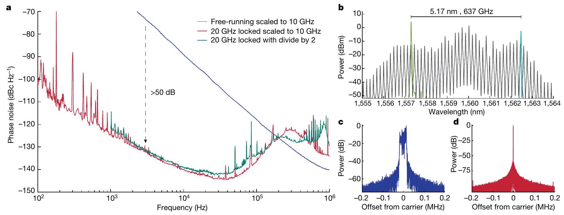
اثنان (أخضر). ب، الطيف البصري للميكروكومب (رمادي) ولازرات SIL (أخضر وزمردي). ج، د، طيف الترددات الراديوية لإشارة 20 جيجاهرتز في حالة التشغيل الحر (عرض النطاق الترددي للدقة (RBW) 100 هرتز؛ ج) ومقفل (RBW 1 هرتز؛ د).
مكونات ضوئية يمكن دمجها جميعًا على شريحة واحدة بحجم إجمالي لمكونات الضوء يبلغ تقريبًا يظهر مفهوم مثل هذا النظام المتكامل بالكامل في الشكل 5a وسيكون مكونًا من ليزر متكامل بشكل غير متجانس بالقرب من
الشكل 4 | مقارنة ضوضاء الطور لتوليد الميكروويف المستند إلى الميكروكومب. تم ضبط المنصات جميعها على تردد 10 جيجاهرتز وتم تصنيفها بناءً على قدرة التكامل لمولد الميكروكومب ومصدر الليزر المرجعي، مع استبعاد الأجزاء البصرية/الكهربائية المتصلة. المربعات المملوءة (الفارغة) تستند إلى نهج OFD (الميكروكومب المستقل): (i) ميكروكومب سيليكا بتردد 22 جيجاهرتز ; (ii) ميكروكومب ; (iii) ميكروكومب ; (iv) ميكروكومب 22 جيجاهرتز ; (v) ميكروكومب ; (vi) 100 جيجاهرتز ميكروكومب ; (vii) 22 جيجاهرتز مثبت بالألياف ميكروكومب ; (ثامناً) ميكروكومب ; (ix) ميكروكوم مضخوم بواسطة ليزر فائق الاستقرار ; و (x) مذبذب نقل قائم على الميكروكوم بتردد 14 جيجاهرتز . SSB، النطاق الجانبي المفرد.
الشكل 5| تصميم تخطيطي لمذبذب ميكروويف ضوئي على شريحة واحدة. يستخدم النظام المتكامل نفس العناصر الضوئية الرئيسية المستخدمة في هذا العمل. يتم قفل ليزرين من نوع SIL مع resonator حلزوني باستخدام تقنية PDH إلى نفس تجويف F-P الميكروي مع جهازين EOM متسلسلين لكل ليزر SIL – الأول لتصحيح الطور السريع والثاني لأطياف PDH الجانبية. يظهر الجانب الأيمن من المخطط واجهة تجويف F-P، حيث يتم تمرير مسارات ليزر SIL عبر مقياس تداخل مع
شبكية انقسام الاستقطاب المدمجة. تعمل هذه كدائرة إلغاء الانعكاس بينما تشكل أيضًا وضع الموجة المسطحة لتتناسب مع وضع . الانعكاس من ثم يتم الكشف عن التجويف بواسطة الكاشف الأيمن. الصورة المصغرة تظهر صورة للتجويف المصغر F-P المكون من مرايا مصنوعة بتقنية الميكروفابريكيشن. ، بحجم إجمالي يقارب مقياس الرسم، حوالي 1 سم. تم إعادة إنتاج التوضيح بإذن من ب. لونغ.
(المرجع 6)، الرنانات الحلزونية لـ SIL، رنان حلقة مزدوجة ميكروكومب كواشف ضوئية وقبة F-P مصغرة مصنوعة بتقنية النانو لا تتطلب فراغًا عاليًا .
العمل السابق قد وضع بالفعل الخطوات للتكامل غير المتجانس لليزر و الرنانات. على سبيل المثال، الليزر تم دمج الرنانات على نفس الشريحة مع الربط بين الكسب البصري وطبقات الموجات الضوئية ذات الخسائر المنخفضة التي تسهلها التقلصات الأديباتية، مع خسائر موجة الرنان تصل إلى مع وجود ثانٍ مدفون بعمق طبقة دليل الموجات تعد هذه التكاملات غير المتجانسة مع الرنانات ذات الجودة العالية للغاية بتشغيل خالٍ من العوازل. تم استخدام استراتيجية مماثلة لدمج الليزر بسمك 780 نانومتر مشط ميكروي بتشتت شاذ على نفس الشريحة التي يمكن تطبيقها على سمك 100 نانومتر تم استخدام مجاميع الميكرو صفر GVD في هذا العمل. علاوة على ذلك، تم أيضًا إثبات تكامل الليزر مع المعدلات والكواشف سابقًا. ويمكن استخدامها للتكامل الكامل لجميع المكونات البصرية التي تتكون منها نظام قفل PDH .
إن دمج المكونات النشطة والسلبية على منصة واحدة يقلل بشكل كبير من الفقد (بين الألياف والرقاقة) ويزيل الحاجة إلى المعززات الضوئية التي استخدمناها في العمل الحالي. في هذه الحالة، يتطلب الأمر بضع عشرات من الميلي واط من الطاقة الضوئية لضخ الرنان بحيث يكون من الواقعي الحصول على مجموعة تحتوي على بضع ميلي واط من الطاقة الضوئية وعدة ميكرو واط لكل وضع. بالإضافة إلى ذلك، بالنسبة لليزر SIL، يتطلب الأمر فقط عدة ميلي واط من الطاقة الضوئية DFB لتوفير مئة ميكرو واط من الطاقة الضوئية للتداخل مع المجموعة وتحقيق نسبة الإشارة إلى الضوضاء (SNR) اللازمة لمطابقة الأداء المقدم في هذا العمل. بالنسبة لليزر المدمجة الحديثة، فإن هذه القوى واقعية. تمت مناقشة اعتبارات إضافية حول القدرة الضوئية المطلوبة في الطرق.
لقد كانت عملية دمج تجويف F-P تحديًا بارزًا، ولكن التطورات الأخيرة في المرايا المصغرة قد ومحدود الضوضاء الحرارية المدمجة تصاميم توفير فرص تكامل جديدة. من المهم أن تم إثبات أن 2P-OFD لا يتطلب تشغيل F-P في الفراغ العالي بسبب ، مما يبسط بشكل كبير التكامل المستقبلي. الشكل 5 يوضح فراغ مع مرايا ميكرو مصنوعة وتفاصيل حول استراتيجية التكامل مع ليزرات SIL والميكروكومب. يقوم دليل الموجات المسطح بتغذية شبكة تقسيم الاستقطاب المصممة بشكل عكسي المدمجة في جهاز تداخل، والذي يعمل على تشكيل الشعاع لربط الضوء بالفراغ بينما يوفر أيضًا
إشارة قفل PDH المنعكسة من التجويف وعزل الليزر تظهر القياسات الأولية الموصوفة في الطرق جدوى هذا النهج. يمكن ربط تجويف فابري-بيرو وعدسة ذات مؤشر تدرجي (GRIN) فوق شبكة تقسيم الاستقطاب بطريقة هجينة على شكل شريحة مقلوبة لوحدة مولد ميكروويف متكاملة في شريحة واحدة ومنخفضة الضوضاء.
في مخطط التكامل، يمكن استبدال المحولات الصوتية الضوئية (AOMs) بمزيج من التغذية الراجعة البطيئة إلى السخانات المدمجة أو المكونات الكهروضغطية. في الحلزونات والتغذية الراجعة السريعة إلى DFB الحالية وEOMs يمكن أن تصل الضبط الحراري إلى عرض نطاق يصل إلى بضع كيلوهرتز بينما يمكن توفير التغذية الراجعة السريعة بعرض نطاق يبلغ عدة ميغاهرتز بواسطة EOM أو تعديل التيار . نحن نقدر أن هذا المزيج يمكن أن يوفر ربح تغذية مرتدة قدره 40 ديسيبل عند تردد إزاحة 10 كيلوهرتز لمطابقة أداء ضوضاء الطور للعمل المقدم. لتقليل حجم النظام بالكامل بشكل أكبر، يمكن توليد ترددات التعديل لتأمين PDH، بالإضافة إلى تأمين الطور للتردد الوسيط، باستخدام جهاز توليد رقمي مباشر، يتم توقيته بواسطة الموجات الدقيقة المستمدة من الميكروكومب نفسه. .
في الملخص، لقد أظهرنا نهجًا ضوئيًا متكاملًا لتقنية OFD ينتج إشارات ميكروويف بتردد 20 جيجاهرتز مع ضوضاء طور عند انزياح 10 كيلوهرتز، وهو قيمة نموذجية للأنظمة التجارية الأكبر بكثير الموجودة. يتم تحقيق ذلك من خلال مزيج فريد من الليزر المتكامل منخفض الضوضاء، ومجموعة ترددات السوليتون المظلم الفعالة، والتقدمات الجديدة في تجويف فابري-بيرو البصري المصغر. ومن المهم أن نهجنا يوفر طريقًا للتكامل الكامل على شريحة واحدة بحجم مكونات الفوتونيات في حدود يمثل هذا التقدم في توليد الموجات الدقيقة منخفضة الضوضاء باستخدام الفوتونيات المتكاملة وعدًا بتوفير توليفات موجات دقيقة مدمجة ومحمولة ومنخفضة التكلفة لمجموعة واسعة من التطبيقات المت demanding في الملاحة والاتصالات والتوقيت الدقيق.

المحتوى عبر الإنترنت

أي طرق، مراجع إضافية، ملخصات تقارير Nature Portfolio، بيانات المصدر، بيانات موسعة، معلومات تكميلية، شكر وتقدير، معلومات مراجعة الأقران؛ تفاصيل مساهمات المؤلفين والمصالح المتنافسة؛ وبيانات توفر البيانات والرموز متاحة علىhttps://doi.org/10.1038/s41586-024-07058-z.
  1. فورتييه، ت. م. وآخرون. توليد ميكروويف فائقة الاستقرار عبر تقسيم التردد البصري. نات. فتون. 5، 425-429 (2011).
  2. ناكامورا، ت. وآخرون. تحويل الترددات الضوئية المتماسكة إلى ترددات الميكروويف مع عدم الاستقرار. العلوم 368، 889-892 (2020).
  3. شيا، إكس. وآخرون. إشارات ميكروويف ضوئية مع ضوضاء توقيت مطلقة بمستوى زبتوثانية. نات. فوتون. 11، 44-47 (2017).
  4. سوان، و. س.، باومان، إ.، جورجيتا، ف. ر. ونيو بيري، ن. ر. توليد الميكروويف مع ضوضاء طور متبقية منخفضة من ليزر ألياف فمتوثانية مع معدل تعديل كهربائي بصري داخل التجويف. أوبت. إكسبريس 19، 24387-24395 (2011).
  5. لي، ج.، يي، إكس.، لي، إتش.، ديدامز، س. أ. وفاهالا، ك. ج. تقسيم الترددات الكهروضوئية وتركيب الميكروويف المستقر. العلوم 345، 309-313 (2014).
  6. Guo، ج. وآخرون. ليزر قائم على الرقاقة مع عرض خط متكامل 1 هرتز. Sci. Adv. 8، eabp9006 (2022).
  7. لي، ب. وآخرون. الوصول إلى تماسك ليزر الألياف في الفوتونيات المتكاملة. رسالة أوبتيكس 46، 5201-5204 (2021).
  8. كيلهير، م. ل. وآخرون. تجويف بصري مضغوط ومحمول محدود بالضوضاء الحرارية مع حساسية منخفضة للتسارع. أوبت. إكسبريس 31، 11954-11965 (2023).
  9. جي، كيو.-إكس. وآخرون. تصميم ميكروكومبز بدون تشتت باستخدام الفوتونيات الجاهزة لتقنية CMOS. أوبتيكا 10، 279-285 (2023).
  10. ماتي، د. وآخرون. ليزرات بعرض خط أقل من 10 ميجاهرتز. مجلة مراجعة الفيزياء. 118، 263202 (2017).
  11. ديدامز، س. أ.، فاهالا، ك. وأوديم، ت. مشط الترددات البصرية: توحيد الطيف الكهرومغناطيسي بشكل متماسك. العلوم 369، eaay3676 (2020).
  12. كالوبوفيلاجي، م.، إندو، م. وشيبلي، ت. ر. ميكروويف ضوئي بتردد X-band مع ضوضاء طور أقل من باستخدام مشط أحادي الكتلة يعمل بحرية. Opt. Express 30، 11266-11274 (2022).
  13. مارتن، م. ج. ويي، ج. في الطلاءات البصرية والضوضاء الحرارية في القياسات الدقيقة (تحرير هاري، ج. م. وآخرون) 237-258 (مطبعة جامعة كامبريدج، 2012).
  14. جين، و. وآخرون. ليزر أشباه الموصلات بعرض خط هيرتز باستخدام ميكرو ريزوناتور عالي الجودة جاهز لتقنية CMOS. نات. فوتون. 15، 346-353 (2021).
  15. شيانغ، سي. وآخرون. ليزر عالي الأداء للضوئيات المتكاملة بالكامل من نيتريد السيليكون. نات. كوميون. 12، 6650 (2021).
  16. جين، ن. وآخرون. مرايا مصغرة مصنوعة بتقنية النانو بدقة تتجاوز مليون. أوبتيكا 9، 965-970 (2022).
  17. ماكليمور، سي. إيه. وآخرون. تصغير المذبذبات الكهرومغناطيسية فائقة الاستقرار: عدم استقرار التردد أقل من 10¹⁴ من خلال تجويف فابري-بيرو بحجم سنتيمتر. فيزي. ريف. أبليد. 18، 054054 (2022).
  18. ليو، ي. وآخرون. توليد ميكروويف منخفض الضوضاء باستخدام تجويف مرجعي بصري بفجوة هوائية. APL فوتونيكس 9، 010806 (2024).
  19. دريفر، ر. و. وآخرون. تثبيت الطور والتردد بالليزر باستخدام رنان بصري. فيزياء تطبيقية ب 31، 97-105 (1983).
  20. باب، س. ب. وآخرون. ساعة ضوئية من مشط تردد الميكرو ريزوناتور. أوبتيكا 1، 10-14 (2014).
  21. كوان، د.، جونغ، د.، جيون، إ.، لي، هـ. وكيم، ج. توليد ميكروويف فائق الاستقرار ونبضات سوليتون من ميكروكومب مثبت بالألياف الضوئية. نات. كوميونيك. 13، 381 (2022).
  22. زانغ، ج. وآخرون. تقليل تحويل السعة إلى الطور في الكاشفات الضوئية المعدلة ذات الحمل المعوض. مجلة تكنولوجيا الضوء 36، 5218-5223 (2018).
  23. لي، هـ. وأبراهام، ن. تحليل طيف الضوضاء لدايود الليزر مع تغذية بصرية من رنان عالي الجودة. مجلة IEEE للإلكترونيات الكمومية 25، 1782-1793 (1989).
  24. إندو، م. وشيبلي، ت. ر. قمع الضوضاء الطورية المتبقية لتثبيت تجويف باوند-دريفر-هال باستخدام معدل كهربائي بصري. أوسا كونتينوم 1، 116-123 (2018).
  25. جي، ك. وآخرون. ميكروكومب متكامل مع تشتت عادي وغير عادي قابل للتعديل. في اجتماع أوبتيكا للضوء غير الخطي 2023، سلسلة المطبوعات الفنية Tu1A-2 (مجموعة نشر أوبتيكا، 2023).
  26. بافلوف، ن. وآخرون. الليزر ذو العرض الضيق والميكروكومبز السوليتونية كير مع ثنائيات الليزر العادية. نات. فوتون. 12، 694-698 (2018).
  27. شين، ب. وآخرون. ميكروكومبز سوليتون متكاملة جاهزة. ناتشر 582، 365-369 (2020).
  28. بينغ، ي.، صن، ك.، شين، ي.، بيلينغ، أ. وكامبل، ج. سي. التوليد الضوئي لإشارات الميكروويف النبضية في نطاقات إكس وكيو وك. أوبت. إكسبريس 28، 28563-28572 (2020).
  29. شيا، إكس. وآخرون. تحسين كفاءة تحويل الطاقة في الكاشفات الضوئية عالية الأداء من خلال الربط العكسي على الماس. أوبتيكا 1، 429-435 (2014).
  30. Weng، و. وآخرون. تنقية طيفية لإشارات الميكروويف باستخدام سوليتونات كير المبددة المنضبطة. فيز. ريف. ليت. 122، 013902 (2019).
  31. لوكاس، إ. وآخرون. توليف ميكروويف فوتوني منخفض الضوضاء للغاية باستخدام مذبذب نقل قائم على مجمع السوليتون. نات. كوميونيك. 11، 374 (2020).
  32. ليو، ج. وآخرون. توليد الموجات الميكروية الضوئية في نطاقي x و k باستخدام ميكروكومبز السوليتون المتكاملة. نات. فوتون. 14، 486-491 (2020).
  33. سون، س. وآخرون. تقسيم التردد البصري المتكامل لتوليد الموجات الدقيقة والموجات المليمترية. الطبيعةhttps://doi.org/10.1038/s41586-024-07057-0 (2024).
  34. Yi، X. وآخرون. موجات متشتتة أحادية الوضع وديناميات ميكروكومب السوليتون. نات. كوميونيك. 8، 14869 (2017).
  35. يانغ، ك.-ف. وآخرون. حدود الضوضاء الناتجة عن الموجات المشتتة في مصادر الميكروويف السوليتونية الصغيرة. نات. كوميونيك. 12، 1442 (2021).
  36. ياو، ل. وآخرون. مذبذبات الموجات الميكروية السوليتونية باستخدام مليار ضخم المرايا الدقيقة البصرية. أوبتيكا 9، 561-564 (2022).
  37. تشاو، ي. وآخرون. تقسيم التردد البصري بالكامل على الرقاقة باستخدام ليزر واحد. ناتشر https:// doi.org/10.1038/s41586-024-07136-2 (2024).
  38. OEWaves. OE3700 Hi-Q X-band OEO. OEWaveshttps://www.oewaves.com/oe3700 (2020).
  39. لي، ج. وفاهالا، ك. مذبذبات ميكروويف ضوئية صغيرة الحجم ذات ضوضاء طور منخفضة للغاية في نطاقات إكس-كا. أوبتيكا 10، 33-34 (2023).
  40. مختبرات كوانتكس. مذبذبات ذات ضوضاء طور منخفضة للغاية. أنقى مصدر تردد. X-LNO. مذبذب ميكروويف ذو ضوضاء منخفضة للغاية. مختبرات كوانتكسhttps://www.quantxlabs.com/القدرات/تطوير المنتجات/المذبذبات ذات الضوضاء الطورية المنخفضة للغاية/(2022).
  41. شيانغ، سي. وآخرون. التكامل ثلاثي الأبعاد يمكّن الليزر الخالي من العوازل ذات الضوضاء المنخفضة للغاية في الفوتونيات السيليكونية. ناتشر 620، 78-85 (2023).
  42. شيانغ، سي. وآخرون. ميكروكومبز سوليتون بالليزر مدمجة بشكل غير متجانس على السيليكون. ساينس 373، 99-103 (2021).
  43. شيا، و. وآخرون. استشعار الفوتونيات السيليكونية غير المتجانسة للسيارات الذاتية القيادة. أوبت. إكسبريس 27، 3642-3663 (2019).
  44. إدجادي، م. هـ. وأفلاتوني، ف. نظام تثبيت ليزر باوند-دريفر-هال المتكامل في السيليكون. نات. كوميونيك. 8، 1209 (2017).
  45. تشنغ، هـ. وآخرون. نهج جديد لربط رنانات فابري-بروت عالية الجودة مع الدوائر الضوئية. APL Photon. 8، 116105 (2023).
  46. ليو، ج. وآخرون. التحكم الكهروضغطي الأحادي في ميكروكومب السوليتون. الطبيعة 583، 385-390 (2020).
  47. جوشي، سي. وآخرون. توليد المشط تحت التحكم الحراري ونمذجة السوليتون في الميكرو ريزوناتورز. رسالة أوبتيك. 41، 2565-2568 (2016).
  48. ديدامز، س. أ. وآخرون. ساعة ضوئية تعتمد على حبس مفرد أيون. العلوم 293، 825-828 (2001).
  49. فورتييه، ت. وآخرون. جهاز توليد إلكتروني عريض النطاق مرجعي بصريًا بدقة 15 رقم. مراجعة ليزر وفوتون. 10، 780-790 (2016).
  50. يي، إكس.، يانغ، كيو-إف.، يانغ، كاي. واي.، سوه، م.-جي. وفاهالا، ك. مجموعة ترددات السوليتون بمعدلات الميكروويف في رنان ميكروي من السيليكا عالي الجودة. أوبتيكا 2، 1078-1085 (2015).
  51. لي، ج.، لي، هـ.، تشين، ت. وفاهالا، ك. ج. تشغيل معدل التكرار في الميكروكومبز بقوة مضخة منخفضة، وضوضاء طور منخفضة، ومن الميكروويف إلى الموجات المليمترية. فيز. ريف. ليت. 109، 233901 (2012).
  52. ليانغ، و. وآخرون. مذبذب فوتوني بتردد كير عالي النقاء الطيفي. نات. كوم. 6، 7957 (2015).
  53. ماتسكو، أ. وآخرون. تشغيل جاهز واستقرار أطياف كير. في ندوة التحكم في التردد الدولية IEEE لعام 2016 (IFCS) 1-5 (IEEE، 2016).
ملاحظة الناشر: تظل شركة سبرينغر ناتشر محايدة فيما يتعلق بالمطالبات القضائية في الخرائط المنشورة والانتماءات المؤسسية.
الوصول المفتوح هذه المقالة مرخصة بموجب رخصة المشاع الإبداعي النسب 4.0 الدولية، التي تسمح بالاستخدام والمشاركة والتكيف والتوزيع وإعادة الإنتاج بأي وسيلة أو صيغة، طالما أنك تعطي الائتمان المناسب للمؤلفين الأصليين والمصدر، وتوفر رابطًا لرخصة المشاع الإبداعي، وتوضح إذا ما تم إجراء تغييرات. الصور أو المواد الأخرى من طرف ثالث في هذه المقالة مشمولة في رخصة المشاع الإبداعي الخاصة بالمقالة، ما لم يُشار إلى خلاف ذلك في سطر الائتمان للمواد. إذا لم تكن المادة مشمولة في رخصة المشاع الإبداعي الخاصة بالمقالة وكان استخدامك المقصود غير مسموح به بموجب اللوائح القانونية أو يتجاوز الاستخدام المسموح به، فستحتاج إلى الحصول على إذن مباشرة من صاحب حقوق الطبع والنشر. لعرض نسخة من هذه الرخصة، قم بزيارةhttp://creativecommons.org/licenses/by/4.0/.
(ج) المؤلف(ون) 2024

طرق

توصيف مساهمات الضوضاء في ضوضاء الميكروويف

تظهر البيانات الموسعة الشكل 1 ضوضاء الطور لمكونات مختلفة تساهم في إشارة 20 جيجاهرتز المولدة. يشمل ذلك ضوضاء الطور في الحلقة ونسبة الإشارة إلى الضوضاء لكل ليزر موجي مستمر وتردد الوسيط، ونسبة الإشارة إلى الضوضاء لحامل 20 جيجاهرتز وضوضاء الشدة المتوقعة على ضوضاء الميكروويف بسبب رفض السعة إلى الطور. تم تقدير ضوضاء الطور في الحلقة لليزر الموجي المستمر كما هو موصوف في المرجع 54. يتم تقدير نسبة الإشارة إلى الضوضاء لليزر الموجي المستمر بطريقة مشابهة ولكن عندما تكون الليزر غير مقفلة ومزاحة عن رنين تجويف F-P. تم قياس ضوضاء الطور في الحلقة للتردد الوسيط مباشرة باستخدام نظام قياس ضوضاء الطور التجاري. لاحظ أن مصطلحات الضوضاء المقاسة المذكورة أعلاه، باستثناء تحويل السعة إلى الطور، تم تقليلها بمقدار 30 ديسيبل لحساب تقليلها بسبب OFD. تم تحديد تحويل السعة إلى الطور من ضوضاء الشدة النسبية المقاسة للميكروكومب على كاشف MUTC بعد تقليلها بواسطة رفض السعة إلى الطور (40 ديسيبل). تم قياس قيمة الرفض عن طريق تعديل قوة الميكروكومب الضوئية ومقارنة قوة نغمة تعديل السعة مع تعديل الطور الناتج على حامل 20 جيجاهرتز.
عند الترددات التي تقل عن 1 كيلوهرتز، تكون ضوضاء الطور لإشارة 20 جيجاهرتز محدودة بضوضاء الإلكترونيات لقفل PDH، والتي يمكن تحسينها عن طريق زيادة تقليل ضوضاء الطور 2P-OFD (أي، باستخدام ميكروكومب بعرض نطاق أوسع). عند الترددات التي تزيد عن عدة عشرات من الكيلوهرتز، تزداد ضوضاء الطور بسبب الكسب المحدود وعرض النطاق لحلقة التغذية الراجعة للميكروكومب. تتبع ضوضاء الطور لإشارة 20 جيجاهرتز عند الترددات التي تزيد عن 1 ميغاهرتز ضوضاء الطور للإشارة الحرة، والتي يمكن العثور عليها في المرجع 9. يمكن تقليل الضوضاء عالية التردد باستخدام حالة ميكروكومب حرة أكثر استقرارًا أو عن طريق تحسين عرض نطاق التغذية الراجعة. كما يمكن ملاحظته، في النطاق بين 1 و40 كيلوهرتز، لا تؤثر مساهمات الضوضاء المدرجة على توليد الميكروويف، والذي ينخفض كما . مصدر محتمل للضوضاء في هذه المنطقة هو ضوضاء الميكروكومب التي لا تتعلق بين الأوضاع المفصولة بحوالي 640 جيجاهرتز. قيد آخر محتمل يحد من مستوى الضوضاء هو الكسب المحدود للخدمة، الذي يوفر بالفعل أكثر من 50 ديسيبل تقليل في تلك المنطقة. سيسمح تخفيف هذه القيود بتقليل إضافي للضوضاء في تلك المنطقة يصل إلى 10 ديسيبل.

الإلكترونيات لتثبيت الميكروكومب وقياس ضوضاء الطور

تظهر البيانات الموسعة الشكل 2a الإلكترونيات المستخدمة لتثبيت الميكروكومب. يتم تصفية وتضخيم ومزج كل من نغمات الضرب بين الليزر الموجي المستمر وأسنان الميكروكومب معًا لإنتاج التردد الوسيط ( ) عند 2.6 جيجاهرتز. يتم تضخيم تردد IF بشكل أكبر ومزجه مع مذبذب مرجعي لإنتاج إشارة خطأ لتثبيت الميكروكومب. يتم تغذية إشارة الخطأ إلى خدمة، والتي توفر تغذية راجعة لمصدر التيار لليزر البذور. لاحظ أن ضوضاء المذبذب المرجعي في هذه الخدمة مقسمة بواسطة 2P-OFD، وفي تنفيذ مستقبلي، يمكن الحصول عليها من تقسيم إشارة 20 جيجاهرتز نفسها.
توضح البيانات الموسعة الشكل 2b الإعداد التجريبي لقياس ضوضاء الطور لإشارة 20 جيجاهرتز. لقياس ضوضاء الطور للميكروكومب، استخدمنا الميكروويف الفائق الاستقرار من مزيج تردد Er:fibre المرجعي الذاتي كمذبذب مرجعي. تم استخدام هذا المزيج Er:fibre فقط لأغراض القياس. يتم اكتشاف الإشارة الضوئية للميكروكومب ومزيج Er:fibre المرجعي باستخدام كاشفين MUTC. ثم، يتم تصفية وتضخيم وتقسيم إشارة 20 جيجاهرتز قيد الاختبار و20 جيجاهرتز المرجعية. يتم تضخيم إشارة الميكروويف المرجعية بشكل أكبر لتشبع الخلاطات. يتم مزج كل ذراع من إشارة الميكروويف من الميكروكومب مع الميكروويف المرجعي ل
إنتاج إشارتين عند 47 ميغاهرتز. يتم استخدام ذراعين للتداخل المتقاطع لإزالة الضوضاء الإضافية من مضخمات الميكروويف في الفرع المرجعي. تم تحقيق التداخل المتقاطع باستخدام محلل ضوضاء الطور التجاري.
تظهر ضوضاء الطور للإشارة المرجعية 20 جيجاهرتز في البيانات الموسعة الشكل 2c. لقياس ضوضاء الطور للإشارة المرجعية، قمنا بالتداخل المتقاطع معها باستخدام مذبذبين ميكروويف لمدة 3 ساعات. يمثل مستوى القياس التقريبي، الموضح في البيانات الموسعة الشكل 2c، ضوضاء الطور لمذبذبات الميكروويف وكسب التداخل المتقاطع (30 ديسيبل) بسبب العدد المحدود من المتوسطات.

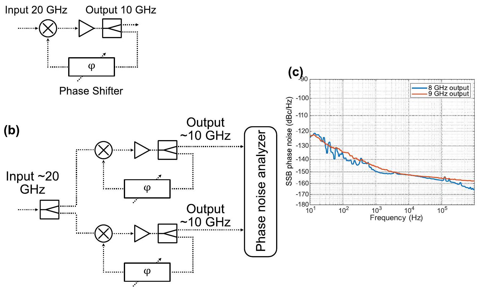
تقسيم تجديدي بمقدار اثنين

تظهر البيانات الموسعة الشكل 3a مخطط التقسيم التجديدي بمقدار اثنين، والذي يتكون من خلاط مزدوج التوازن، ومضخم 10 جيجاهرتز، ومقسم طاقة ومغير طور . يتم استخدام مغير الطور للتحكم في تأخير الطور داخل القسمة. يتم تضخيم الإدخال 20 جيجاهرتز حتى حوالي +13 ديسيبل لتشبع منفذ المذبذب المحلي للخلاط المزدوج التوازن. ثم يتم تضخيم منفذ IF مع إشارة 10 جيجاهرتز وتقسيمها لتوفير إشارة الخرج بقوة حوالي +10 ديسيبل. يتم قياس الخرج 10 جيجاهرتز باستخدام نفس الإعداد كما هو موضح في البيانات الموسعة الشكل 2b، بينما يتم توفير الإشارة المرجعية عند 10 جيجاهرتز من نفس مزيج الألياف.
تقدم البيانات الموسعة الشكل 3b المخطط للإعداد لقياس ضوضاء الطور للقسمة. يتم تقسيم الإشارة المدخلة وتغذيتها إلى قسمين منفصلين. يتم التداخل المتقاطع بين المخرجات من القسمة مع محلل ضوضاء الطور. بسبب التداخل المتقاطع، يتم متوسط الضوضاء المرتبطة بين كلا الإشارتين (تلك الخاصة بالإشارة المدخلة)، مما يوفر ضوضاء الطور للقسمة نفسها. يتم تقديم ضوضاء الطور للقسمة عند ترددات الإدخال للحامل 16 و18 جيجاهرتز في البيانات الموسعة الشكل 3c.

متطلبات الطاقة الضوئية للنظام المتكامل

هنا، نعتبر الطاقة الضوئية المطلوبة لتحقيق الأداء المقدم في الورقة. في العرض التجريبي الموصوف في النص الرئيسي، كان الغرض من المضخمات الضوئية هو تعويض خسائر الاقتران بين ليزر SIL والرقائق وبين الرقائق وألياف العدسات. هذا يضمن أن جميع الإشارات المكتشفة ضوئيًا كانت لديها القوة اللازمة لزيادة نسبة الإشارة إلى الضوضاء، المحدودة بالضوضاء الحرارية، إلى المستوى المطلوب. تظهر البيانات الموسعة الشكل 4a نسبة الإشارة إلى الضوضاء القابلة للتحقيق كدالة لقوة الميكروكومب الضوئية عند مقارنتها بمستوى الضوضاء الذي يتكون من الضوضاء الحرارية وضوضاء الطلقة. هنا، نفترض الكشف باستخدام MUTC الذي لديه كفاءة كمية تبلغ 0.5. للوصول إلى نفس الأداء الذي نعرضه في هذا العمل الحالي، ولكن بدون تضخيم ضوئي، سيتطلب الأمر فقط بضع مئات من الميكرووات من قوة الميكروكومب على كاشف 20 جيجاهرتز. تظهر البيانات الموسعة الشكل 4b نسبة الإشارة إلى الضوضاء لنغمات الضرب مقابل القوة الضوئية لليزر SIL لثلاث قوى مختلفة لأسنان المزيج. كما يمكن ملاحظته، للوصول إلى الأداء المقدم في هذا العمل، سيكون من الكافي دمج عشرات الميكرووات من قوة ليزر SIL مع بضع ميكرووات من قوة أسنان المزيج. في عملنا، كان الكشف الهتروذيني لنغمة الضرب مع ليزر SIL يستخدم أسنان مزيج بقوة حوالي , بينما كانت القوة الإجمالية للميكروكومب قبل الموصلات الضوئية 60 مللي واط. وبالتالي، بافتراض أن الخسائر بعد توليد الميكروكومب مشابهة لهذا العمل، لتوفير قوة أسنان مزيج بضع ميكرووات مع طيف مشابه كما هو موضح في الشكل 2، سيكون مطلوبًا فقط عدة مللي واط من إجمالي الطاقة الضوئية للميكروكومب. لتوفير عشرات الميكرووات من ليزر SIL المرجعي للتداخل الهتروذيني، تكون الطاقة الضوئية في حدود بضع مئات من الميكرووات من الرنان الحلزوني مطلوبة. وهذا يعني فقط بضع مللي واط من الطاقة مباشرة من ليزر DFB.
ومع ذلك، فإن التكامل على شريحة واحدة سيساهم في تخفيف خسائر الاقتران وزيادة كفاءة النظام. بالإضافة إلى ذلك، فإن إزالة AOMs ستعمل على تحسين قوة ليزر SIL المرجعية بحوالي ، وهو فقد الإدخال لأجهزة AOM التي استخدمناها. في الختام، هذه الأرقام واقعية لتحقيقها مع الليزر المتكاملة الحالية. .

فراغ مع مرايا مصغرة مصنوعة بتقنية النانو

في هذا العمل، نقترح استخدام تجويف مع مرايا مصنوعة بتقنية الميكروفابريكيشن. ، والذي يمكن تحقيقه في مكعب بحجم إجمالي أقل من ولا يتطلب عملية في الفراغ (مضمن في الشكل 5). يوضح الشكل الإضافي 5a قياس الانخفاض الحلقي لمثل هذه التجويف عند تتميز التجويف بعرض خط يبلغ 60 كيلو هرتز وتوفر دقة تبلغ 428,000 و مليار. تشير هذه القياسات إلى أن مثل هذه التجويف المدمج لديه عرض خط مطلوب لتوفير نسبة الإشارة إلى الضوضاء اللازمة في قفل PDH.
يوضح الشكل التوضيحي 5b تكامل التجويف مع الشريحة بشكل تخطيطي. يتم إعادة توجيه الضوء من الموجّه إلى الموصل الشبكي المدمج. يتم جمع الضوء الناتج من الشبكة باستخدام عدسة GRIN التي تتناسب بشكل مثالي مع مخرج الشبكة إلى وضع التجويف. لتجنب الانعكاس الخلفي من التجويف وإعادة توجيه الإشارة المنعكسة إلى منفذ آخر للكشف PDH، نقوم بتصميم الدوائر على الشريحة التي تظهر في الشكل التوضيحي 5c والمذكورة بمزيد من التفاصيل في المرجع 45. يتم تقسيم الضوء المدخل بنسبة 50/50 ثم إعادة دمجه عند الموصل الشبكي لتقسيم الاستقطاب على الشريحة. إلى شعاع مستقطب دائريًا يتم توجيهه إلى الفضاء الحر. ستقوم الضوء المنعكس من التجويف بتغيير الاتجاه وسيتم جمعه بواسطة موصل الشبكة المنقسمة للاستقطاب. من خلال تداخل استقطابين من الضوء المنعكس في مقسم شعاع على الرقاقة بنسبة 50/50، يتم إلغاء الانعكاس الخلفي، ويتم تحقيق إعادة توجيه الإشارة.
لتوصيف أداء هذا النظام، نستخدم ألياف SMF28 لجمع الضوء الناتج من موصل الشبكية القائم على الاستقطاب. الطرف الآخر من الألياف متصل بعدسة GRIN، التي تنقل الضوء إلى التجويف. تم استخدام النظام كإثبات للمبدأ لقياس النقل والانعكاس الخلفي لنظام الشبكية-GRIN-التجويف؛ وتظهر تلك النتائج في الشكل 5d من البيانات الموسعة. خسارة الإدخال للنظام تبلغ تقريبًا -7 ديسيبل، بينما يتم تقليل الانعكاسات الخلفية نحو مصدر الليزر بمقدار -17 ديسيبل. لاحظ أن هذا النظام يتضمن خسائر إضافية بسبب الألياف المدخلة، ويمكن تحسين الكفاءة بشكل أكبر من خلال تجنب هذه الخطوة. أيضًا، يمكن تحسين نسبة كبح الانعكاس الخلفي بشكل أكبر من خلال تنفيذ موصل قابل للتعديل على الشريحة لتحقيق نسبة تقسيم أكثر مثالية 50/50. توفر هذه النتائج الثقة في أن التجويف المصغر يمكن دمجه بنجاح على شريحة مستوية.

توفر البيانات

جميع البيانات الخاصة بالأرقام في هذه المخطوطة متاحة علىhttps://doi. org/10.6084/m9.figshare.24243511.
54. شميت، ف.، ويتنبرغ، ج.، هانش، ت. و.، أوديم، ت. وأوزاوا، أ. مخطط بسيط لقياس ضوضاء الطور لأنظمة الليزر المستقرة في التجاويف. رسائل أوبتيك. 44، 2709-2712 (2019).
55. هاتي، أ. وآخرون. مقسم تردد متجدد ذو ضوضاء منخفضة للغاية. مجلة IEEE للالتراسونيك والفيروإلكتريك والتحكم في التردد 59، 2596-2598 (2012).
56. زعوي، و. س.، كونز، أ.، فوجل، و. و بيروث، م. موصلات شق التقطيع القطبي المتوافقة مع CMOS مع مرآة معدنية خلفية. رسالة تكنولوجيا الفوتونيات IEEE 25، 1395-1397 (2013).
الشكر والتقدير نشكر B. Long على الرسم التوضيحي في الشكل 5 و K. Chang و N. Hoghooghi على التعليقات حول المخطوطة. تم تحديد المعدات التجارية وأسماء العلامات التجارية من أجل الوضوح العلمي فقط ولا تمثل تأييدًا من NIST. تم إجراء البحث المبلغ عنه هنا بواسطة W.Z. و V.I. و A.M. في مختبر الدفع النفاث في معهد كاليفورنيا للتكنولوجيا بموجب عقد مع إدارة الطيران والفضاء الوطنية. تم دعم هذا البحث من قبل برنامج DARPA GRYPHON (المنحة HROO11-22-2-0009) وإدارة الطيران والفضاء الوطنية (المنحة 80NMOO18DOOO4) و NIST.
مساهمات المؤلفين: قام P.T.R. و J.E.B. و K.J.V. و A.M. و F.Q. و S.A.D. بتصميم التجربة والإشراف على المشروع. كتب I.K. و W.G. الورقة بمشاركة جميع المؤلفين. قام I.K. و W.G. مع Q.-X.J. و J.G. ببناء التجربة وأداء تجربة تقسيم التردد البصري. أعدت L.W. حزم ليزر الفراشة ذات التغذية المرتدة للتجربة. أعد Q.-X.J. و J.G. و W.J. و L.W. و C.X. و L.C. الميكروكومب والرنانات الحلزونية للتجربة. قام M.L.K. و F.Q. ببناء تجويف فابري-بيرو. قدم D.L. و T.N. و C.A.M. و Y. Liu و F.Q. مرجع الميكروويف المستمد بصريًا وساعدوا في نظام قياس ضوضاء الطور الميكروويفي. قدم P.S. و S. Hanifi و S.M.B. دائرة التقسيم المتجددة. ساهم H.C. و N.J. و S. Halladay و Z.D. و Y. Luo و O.M. و F.Q. و P.T.R. في مخطط تكامل التجويف. ساهم W.Z. و V.I. و A.M. في تحليل تحديد ضوضاء الطور وتكامل النظام. قدم J.B. و J.C.C. كاشفات الناقلات المتنقلة المعدلة. ساهم جميع المؤلفين في تصميم النظام ومناقشة النتائج.
المصالح المتنافسة يعلن المؤلفون عدم وجود مصالح متنافسة.

معلومات إضافية

معلومات إضافية النسخة الإلكترونية تحتوي على مواد إضافية متاحة فيhttps://doi.org/10.1038/s41586-024-07058-z.
يجب توجيه المراسلات والطلبات للحصول على المواد إلى إيغور كوديلين أو سكوت أ. ديدامز.
معلومات مراجعة الأقران تشكر مجلة Nature المراجعين المجهولين على مساهمتهم في مراجعة هذا العمل. تقارير مراجعي الأقران متاحة.
معلومات إعادة الطبع والتصاريح متاحة علىhttp://www.nature.com/reprints.

مقالة

الشكل البياني الممتد 1 | مساهمات الضوضاء في الموجات الدقيقة بتردد 20 جيجاهرتز.
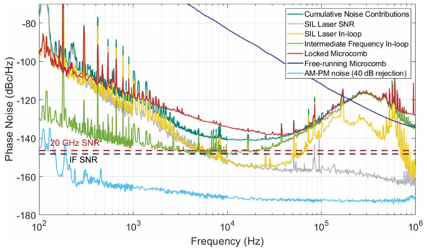
يمثل الضجيج التراكمي مجموع المربعات لجميع مصطلحات الضجيج المعروضة.
يتم عرض ضوضاء الليزر داخل الحلقة فقط لليزر SIL واحد، حيث أن ضوضاء كلا من SIL
الليزر هو نفسه. الخط المنقط الأحمر (الأسود) يوضح حدود نسبة الإشارة إلى الضوضاء (SNR) لتردد الميكروويف 20 جيجاهرتز (التردد الوسيط).
الشكل البياني الموسع 2 | الإلكترونيات الميكروويفية المستخدمة للتثبيت والقياسات. (أ) الإلكترونيات المستخدمة لتوفير التغذية الراجعة لتثبيت الميكروكومب.
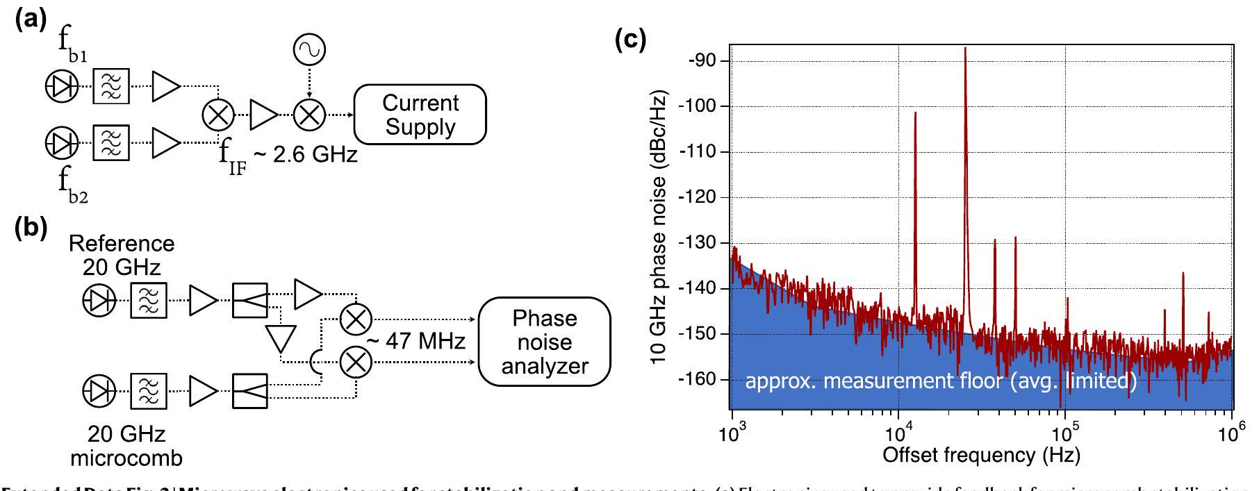
(ب) إعداد قياس ضوضاء الطور لإشارة ميكروويف بتردد 20 جيجاهرتز. (ج) ضوضاء الطور لإشارة 20 جيجاهرتز المرجعية المستخدمة في الارتباط المتقاطع.

مقالة

(أ)
الشكل البياني الممتد 3 | قسمة تجديدية بمعدل 2. (أ) إعداد القسمة التجديدية بمعدل 2. (ب) إعداد تجريبي لقياس ضوضاء الطور للقسمة. (ج) ضوضاء الطور للقسمة التجديدية مقارنةً بحاملات الخرج عند 8 و 9 جيجاهرتز، على التوالي.
الشكل 4 من البيانات الموسعة | متطلبات الطاقة الضوئية. الطاقة الضوئية المقدرة للوصول إلى مستوى ضوضاء الطور المحدد أو نسبة الإشارة إلى الضوضاء (SNR) في (أ) اكتشاف الميكروكومب بتردد 20 جيجاهرتز، و(ب) النغمة الناتجة بين ليزرات SIL والميكروكومب.
(ب)

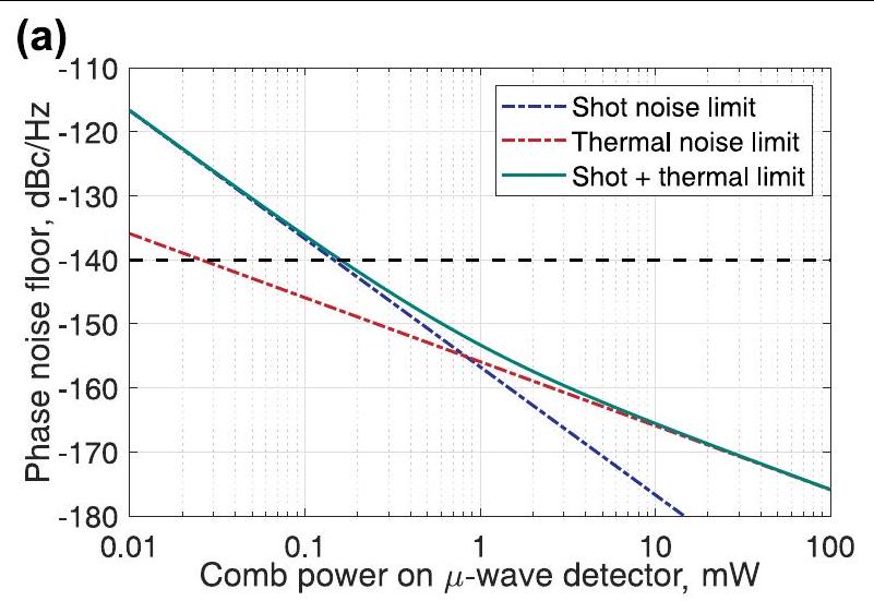
يمثل الخط المنقط الأداء المطلوب لتحقيق النتائج المعروضة في الورقة. تفترض الحسابات كفاءة كوانتوم للكاشف الضوئي تبلغ 0.5.
الشكل البياني الموسع | دمج وتوصيف التجويف مع المرايا المصنوعة بالميكرو. (أ) قياس زمن انتقال الحلقة. التجويف. (ب) مخطط لربط الضوء بالتجويف من خلال شبكة متكاملة وعدسة GRIN. (ج) إعداد الاختبار لقياس الربط إلى
فراغ الميكرو F-P. (د) القدرة الضوئية للضوء المنقول والضوء المنعكس من خلال نظام الشبكة-الألياف-GRIN-فراغ كدالة لتردد الليزر المدخل المختلف.

Journal: Nature, Volume: 627, Issue: 8004
DOI: https://doi.org/10.1038/s41586-024-07058-z
PMID: https://pubmed.ncbi.nlm.nih.gov/38448599
Publication Date: 2024-03-06

Photonic chip-based low-noise microwave oscillator

https://doi.org/10.1038/s41586-024-07058-z
Received: 21 July 2023
Accepted: 11 January 2024
Published online: 6 March 2024
Open access
(A) Check for updates

Igor Kudelin , William Groman , Qing-Xin Ji , Joel Guo , Megan L. Kelleher , Dahyeon Lee , Takuma Nakamura , Charles A. McLemore , Pedram Shirmohammadi , Samin Hanifi , Haotian Cheng , Naijun Jin , Lue Wu , Samuel Halladay , Yizhi Luo , Zhaowei Dai , Warren Jin , Junwu Bai , Yifan Liu , Wei Zhang , Chao Xiang , Lin Chang , Vladimir Iltchenko , Owen Miller , Andrey Matsko , Steven M. Bowers , Peter T. Rakich , Joe C. Campbell , John E. Bowers , Kerry J. Vahala , Franklyn Quinlan & Scott A. Diddams

Abstract

Numerous modern technologies are reliant on the low-phase noise and exquisite timing stability of microwave signals. Substantial progress has been made in the field of microwave photonics, whereby low-noise microwave signals are generated by the down-conversion of ultrastable optical references using a frequency comb . Such systems, however, are constructed with bulk or fibre optics and are difficult to further reduce in size and power consumption. In this work we address this challenge by leveraging advances in integrated photonics to demonstrate low-noise microwave generation via two-point optical frequency division . Narrow-linewidth self-injection-locked integrated lasers are stabilized to a miniature Fabry-Pérot cavity , and the frequency gap between the lasers is divided with an efficient dark soliton frequency comb . The stabilized output of the microcomb is photodetected to produce a microwave signal at 20 GHz with phase noise of at 100 Hz offset frequency that decreases to at 10 kHz offset-values that are unprecedented for an integrated photonic system. All photonic components can be heterogeneously integrated on a single chip, providing a significant advance for the application of photonics to high-precision navigation, communication and timing systems.

Low-noise microwave signals with high timing stability are a critical enabler of modern science and multiple technologies of broad societal impact. Positioning and navigation, advanced communications, high-fidelity radar and sensing, and high-performance atomic clocks are all dependent upon low-phase-noise microwave signals. These rapidly developing technologies are constantly intensifying the demand for microwave sources beyond current capabilities while imposing harsher restrictions on system size, weight, and power consumption (SWaP). In this landscape, photonic lightwave systems provide unique advantages over more conventional electronic approaches for generating low-noise microwaves. In particular, the extremely low-loss and high-quality factors of photonic resonators are fundamental to electromagnetic oscillators with the lowest noise and highest spectral purity . Coupled to this is the introduction and rapid development of frequency combs in the last few decades that enable seamless coherent synthesis across the full electromagnetic spectrum . This includes the frequency division of a optical carrier down to a 10 GHz microwave with unrivalled long- and short-term stability .
However, a significant challenge of these approaches is the relatively large size and power consumption that restrict their use to laboratory environments. Greater impact and widespread use can be realized with a low-noise microwave generator that has a compact and portable form factor for operation in remote and mobile platforms. Our work addresses and overcomes this challenge through the optimal implementation of two-point optical frequency division (2P-OFD) with integrated photonic components as illustrated in Fig. 1. We provide a means to significantly reduce microwave phase noise in a volume of tens of millilitres instead of tens of litres while similarly reducing the required power by a factor to the 1 W level.
All optical frequency division (OFD) systems start with a stable optical frequency reference. Typically, this is a laboratory fibre or solid-state laser that is frequency stabilized to a large evacuated Fabry-Pérot (F-P) cavity . Instead, we introduce an optimal combination of low-noise chip-integrated semiconductor lasers and a new F-P concept that can be miniaturized to less than and chip-integrated without the need for high-vacuum enclosure . The frequency noise of two semiconductor lasers near is reduced by 40 dB through self-injection
Fig. 1| Concept of 2P-OFD for low-noise microwave generation. a, Two semiconductor lasers are injection locked to chip-based spiral resonators. The optical modes of the spiral resonators are aligned, using temperature control, to the modes of the high-finesse F-P cavity for PDH locking. b, A microcomb is generated in a coupled dual-ring resonator and is heterodyned with the two stabilized lasers. The beat notes are mixed to produce an intermediate frequency, , that is phase-locked by feedback to the current supply of the microcomb seed laser.c, An MUTC photodetector chip is used to convert the microcomb’s optical output to a 20 GHz microwave signal.
locking (SIL) to high-Q (quality factor) spiral resonators . This passive stabilization of the SIL laser enables further noise reduction, by up to 60 dB , through Pound-Drever-Hall (PDH) locking to a miniature F-P cavity, reaching the cavity’s thermal noise limit .
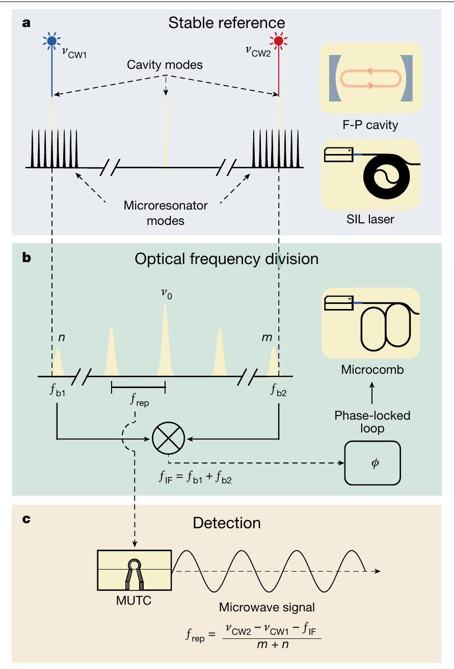
In OFD, the optical phase noise of the reference is then reduced by the square of the ratio of its frequency to that of the microwave output. This is a powerful means for noise reduction by a factor as large as or equivalently, 86 dB . However, significant electrical power is required for generating a frequency comb spanning approximately 200 THz with mode spacing of . Instead, we use the simplified approach of 2P-OFD , with comb bandwidth on the order of 1 THz . This results in a lower division factor, but it also significantly reduced size and power requirements. Such a trade-off still allows us to reach an unprecedented microwave phase noise level with integrated photonics because of the intrinsic low noise of the optical references used.
In our system, the frequency division is implemented with another injection-locked laser that generates a microcomb in a zero group velocity dispersion (GVD) resonator, engineered by two coupled rings
in a Vernier configuration . The microcomb operates without the need for optical amplification, and approximately of the input pump power of 100 mW is efficiently transferred to the comb, which spans nearly 10 nm . 2P-OFD is then implemented by heterodyning the two SIL lasers with the closest comb teeth to produce two beat notes. These are mixed to provide a servo control signal at an intermediate frequency that is independent of the microcomb centre frequency. Upon phase locking of the intermediate frequency, the noise of the microcomb is dramatically reduced. Photodetection of the stabilized microcomb output with a high-power and high-linearity modified unitravelling carrier (MUTC) photodetector provides a 20 GHz microwave signal with phase noise of at 10 kHz offset frequency. This level of noise has not been achieved previously for a system that uses integrated photonic components. We note that the critical photonic devices used in our system can be further integrated to a single chip without the need for fibre or semiconductor amplifiers or optical isolators, providing ultrastable microwave generation in a compact form factor. This advance is important for future applications of high-performance microwave sources with compact size and low-power usage that will operate beyond research laboratories.

Experiment and results

A technical illustration of the setup used for frequency comb stabilization and stable microwave generation is shown in Fig. 2. Here, we elaborate on the operation and characteristics of the key components, concluding with a description of how they function together cohesively to produce low-phase noise microwave signals.

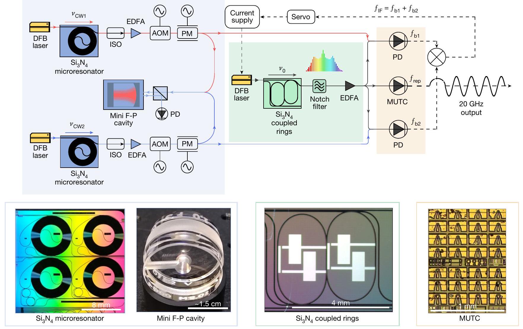
Miniature F-P cavity

The phase and frequency stability of the generated microwave signal is ultimately derived from that of the ultrastable optical reference. The lowest-noise optical references are lasers locked to vacuum-gap F-P cavities, where fractional frequency stability as low as has been demonstrated with -long cryogenic cavity systems . Instead, we use an integrable cavity design based on a compact, rigidly held cylindrical F-P optical reference cavity that supports fractional frequency stability at the level . Ultralow expansion glass with 1 m radius of curvature and an ultralow expansion glass spacer compose the 6.3 mm -long cavity with finesse of approximately billion) and overall volume of less than . The cavity is thermal noise limited for offset frequencies ranging from 1 Hz to 10 kHz . Moreover, the relative phase noise between two reference lasers locked to the same cavity takes advantage of large common-mode rejection (CMR), reaching 40 dB rejection for cavity modes spaced by 1 THz (ref. 18). When combined with 2P-OFD, the cavity noise is expected to be reduced by approximately 80 dB when projected onto the microwave carrier.

Self-injection-locked lasers

To achieve high-stability performance, it is crucial to use narrowlinewidth and frequency-stable lasers. This is because electrical noise from the individual laser locking circuits does not experience CMR, and this noise is reduced only by the 2P-OFD. To address this issue and reach the thermal noise floor of the F-P cavity, we use SIL lasers that are both integrable and have noise performance equivalent to much larger laboratory fibre lasers . With reference to Fig. 2, two commercial semiconductor distributed feedbacks (DFBs) are prestabilized by SIL to a high-Q spiral resonator . When the forward and backward fields between the DFB lasers and the resonators are in phase, resonant backscattered light is fed back to the DFB, anchoring each laser wavelength to the corresponding resonance and significantly suppressing its frequency noise. This passive prestabilization of the DFB lasers is crucial to reach the thermal noise limit of the F-P cavity and reduce the high-frequency noise. The length and Q of the integrated resonator determine the ultimate phase noise of the
Fig. 2 | Experimental setup. Two DFB lasers at 1, 557.3 and are self-injection-locked to spiral resonators, amplified and locked to the same miniature F-P cavity. A 6 nm broad-frequency comb with an approximately 20 GHz repetition rate is generated in a coupled-ring resonator. The microcomb is seeded by an integrated DFB laser, which is self-injection-locked to the coupled-ring microresonator. The frequency comb passes through a notch filter to suppress the central line and is then amplified to 60 mW total optical power. The frequency comb is split to beat with each of the PDH-locked SIL
continuous wave references. Two beat notes are amplified, filtered and then mixed together to produce , which is phase-locked to a reference frequency. The feedback for microcomb stabilization is provided to the current supply of the microcomb seed laser. Lastly, part of the generated microcomb is detected in an MUTC detector to extract the low-noise 20 GHz signal. Photographs of the key photonic components used in low-noise microwave generation are in the lower panels. Scale bars (from left to right), 8 mm ; approximately ; 1 mm. ISO, optical isolator; PM, phase modulator; PD, photodetector.
SIL laser , and here, we use a spiral with a length of 1.41 m that is fabricated on approximately of silicon. The intrinsic and loaded Q factors of the two spiral resonators are 164 and 126 million . The outputs of the SIL lasers are amplified using commercial erbium-doped fibre amplifiers (EDFAs) to approximately 30 mW and then further stabilized via PDH locking to the miniature F-P cavity. In this setup, the primary actuator for PDH stabilization is an acousto-optic modulator; however, the PDH error signal is also fed back to the electro-optical modulator (EOM) to further increase the bandwidth and noise reduction of the PDH servo . The in-loop phase noise of the PDH locking of SIL lasers is presented in Methods.

Microcomb

Robust and low-noise optical frequency comb generation with repetition rate and broad optical coverage is challenging. Here, we use an microresonator fabricated at a complementary metal-oxide semiconductor (CMOS) foundry to generate mode-locked microcombs . To produce dark soliton microcombs with higher bandwidth, we use a dual coupled-ring resonator with free-spectral range (FSR) of 20 GHz (ref. 9), where the zero GVD wavelength is tuned to approximately using integrated heaters . In addition, such microcomb states have high pump-to-comb conversion efficiency, benefiting microwave generation in a low-SWaP system. To generate the comb, a commercial semiconductor DFB laser without optical amplification is self-injection-locked to the dual coupled-ring resonator, which
narrows the linewidth of the pump laser and generates a reasonably stable . Following the coupled rings, a notch filter is used to suppress the central (seed) comb line to avoid saturation in an EDFA, which amplifies the frequency comb up to 60 mW (Fig. 2). Note that the use of a drop port on the coupled-ring resonator can replace the notch filter. A typical comb spectrum after the EDFA is shown in Fig. 3b.

Microcomb stabilization and microwave generation

As outlined above, in this work we use two-point locking to realize OFD for phase noise reduction. With appropriate fibre optic couplers and filters, we design a receiver system to separate heterodyne beat notes and 20 GHz microwave generation. The two beat notes between the microcomb and each continuous wave (CW) laser are given by and (Fig. 1). Here, the comb modes are indexed with signed integers from the central (seed) frequency . These beats are filtered, amplified and mixed together to produce the intermediate frequency ( ), which is then phase-locked to a stable microwave reference via feedback to the current of the microcomb seed laser . The stabilization of is the final step to generate a low-noise microwave via 2P-OFD: , where is the value of the OFD ( 32 in our case) that amounts to 30 dB of noise reduction. Note that two-point locking does not depend on the noise of the microcomb central frequency . Thus, the instability of the microcomb repetition rate can be represented as
Fig. 3|Microcomb characterization. a, Single side-band phase noise scaled to 10 GHz of free-running 20 GHz microcomb (blue), locked 20 GHz microwave (red) and locked 20 GHz microwave after regenerative frequency division by
Although the phase noise of and is reduced by 2P-OFD, their servo control and residual noise can be limiting factors in the achievable microwave phase noise (Methods).
The stabilized microcomb output is directed to an MUTC photodiode, which provides exceptional linearity and large microwave powers . We tune the bias voltage of the MUTC operation for approximately 40 dB rejection of amplitude-to-phase noise conversion while generating a 20 GHz power of -10 dBm at 5 mA of average photocurrent. The 20 GHz microwave signal is filtered and amplified to +3 dBm , and it is sent to a measurement system, with results presented in Fig. 3a. Here, we have scaled the measured 20 GHz phase noise to 10 GHz by subtracting 6 dB . This yields at 100 Hz , which decreases to -141 dBc Hz at 10 kHz . We also compare with a 10 GHz carrier that we generate from 20 GHz with a regenerative divide-by-two circuit. Compared with the free-running microcomb generation, we achieved more than 50 dB phase noise improvement for offset frequencies below 10 kHz . Additional details on the phase noise measurement and divider are in Methods.

Discussion and further integration

Figure 4 places the level of phase noise we achieve in context with other photonic approaches, including recent works based on microcombs and mode-locked laser frequency combs. The comparison is classified by level of photonic integration of the microcomb source and pumping/ reference lasers, as applicable. It is also noted that some of the microcomb systems require the assistance of a fibre-based frequency comb (Fig. 4ix,x) . The phase noise performance of other systems, which could be chip integrated (Fig. 4ii,iii) , is more than 30 dB greater than the results we present, with the exception of the recent work by Sun et al. (Fig. 4vi) . Other notable works on low-noise microwave generation in low-SWaP systems, which are not shown in Fig. 4, include ‘quite point’ operation , single-laser and high-end commercial products .
To the best of our knowledge, this work provides the best phase noise performance in the frequency range of 200 Hz to 40 kHz for microcomb-based systems. Importantly, it does so with integrated
two (green). b, Optical spectrum of microcomb (grey) and SIL lasers (green and turquoise).c,d, Radio frequency spectra of 20 GHz signal free running (resolution bandwidth (RBW) 100 Hz ; c) and locked (RBW1 Hz; d).
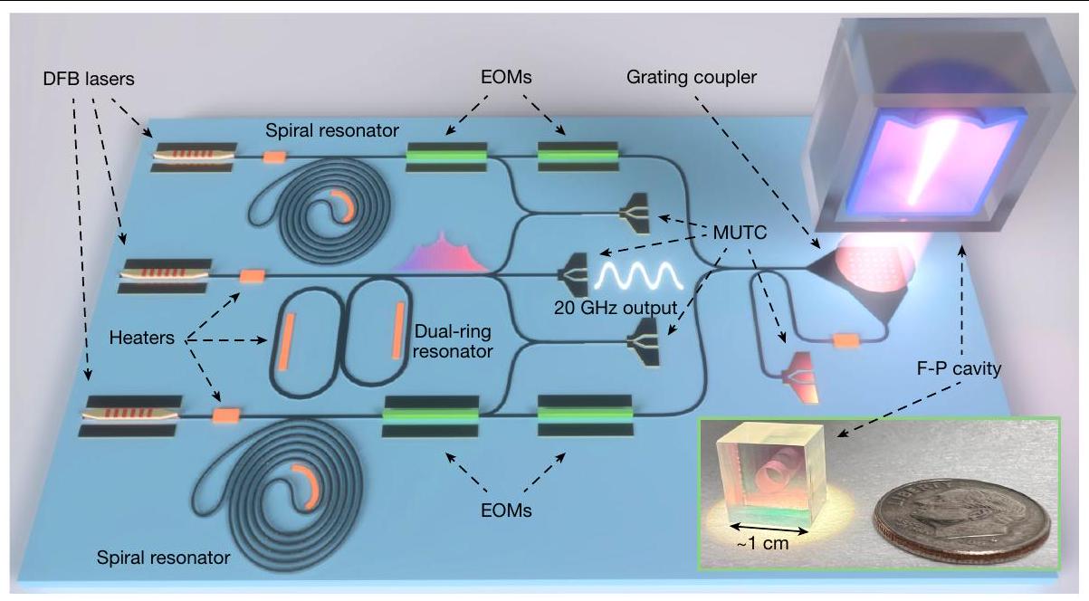
photonic components that can all be further combined onto a single chip with total volume of the photonic components of approximately . A concept of such a fully integrated system is shown in Fig. 5a and would consist of heterogeneously integrated lasers near
Fig. 4 | Phase noise comparison of microwave generation based on microcombs. The platforms are all scaled to 10 GHz carrier and categorized based on the integration capability of the microcomb generator and the reference laser source, excluding the interconnecting optical/electrical parts. Filled (blank) squares are based on the OFD (stand-alone microcomb) approach: (i) 22 GHz silica microcomb ; (ii) microcomb ; (iii) microcomb ; (iv) 22 GHz microcomb ; (v) microcomb ; (vi) 100 GHz microcomb ; (vii) 22 GHz fibre-stabilized microcomb ; (viii) microcomb ; (ix) microcomb pumped by an ultrastable laser ; and (x) 14 GHz microcomb-based transfer oscillator . SSB, Single side band.
Fig. 5|Schematic design of a photonic microwave oscillator on a single chip. The integrated system uses the same key photonic elements used in this work. Two spiral resonator SIL lasers are PDH locked to the same micro-F-P cavity with two EOMs in series for each SIL laser-the first for fast phase correction and the second for PDH side bands. The right side of the schematic shows the F-P cavity interface, where the two SIL laser paths are fed through an interferometer with
an embedded polarization splitting grating. This serves as a reflection cancellation circuit while also shaping the planar waveguide mode to match the mode . The reflection from the cavity is then detected by the right-most detector. The inset shows a photo of the miniature F-P cavity consisting of microfabricated mirrors , with overall volume of approximately . Scale bar, approximately 1 cm . Illustration reproduced with permission from B. Long.
(ref. 6), spiral resonators for SIL, a coupled-ring microcomb resonator , photodetectors and a microfabricated F-P cavity that does not require high vacuum .
Previous work already laid out the steps for heterogeneous integration of lasers and resonators. For example, lasers and resonators have been integrated on the same chip with coupling between the optical gain and low-loss waveguide layers facilitated by adiabatic tapers, with resonator waveguide losses down to with a second deeply buried waveguide layer . This same heterogeneous integration with ultrahigh-Q resonators promises isolator-free operation . A similar strategy has been used for laser integration with 780-nm-thick anomalous dispersion microcombs on the same chip , which can be applied to the 100 -nm-thick zero GVD microcombs used in this work. Furthermore, laser integration with modulators and detectors has also been previously demonstrated and can be utilized for full integration of all the optical components comprising the PDH locking system .
The integration of the active and passive components on a single platform greatly reduces loss (between fibre and chip) and removes the need for the optical amplifiers we have used in the present work. In such a case, a few tens of milliwatts of optical power is required to pump the resonator such that a comb with a few milliwatts of optical power and several microwatts per mode is realistic. Additionally, for the SIL lasers, only several milliwatts of DFB optical power is required to provide a hundred microwatts of optical power to heterodyne with the comb and achieve the signal-to-noise ratio (SNR) necessary to match the performance presented in this work. For recent integrated lasers, these powers are realistic . Additional considerations on required optical power are discussed in Methods.
Integration of the F-P cavity has been an outstanding challenge, but recent developments in microfabricated mirrors and compact thermal-noise-limited designs provide new integration opportunities. Critically, it has been shown that 2P-OFD does not require F-P operation in high vacuum because of , significantly simplifying future integration. Figure 5 shows a cavity with fabricated micromirrors and details on an integration strategy with the SIL lasers and microcomb. A planar waveguide feeds an inverse-designed polarization splitting grating embedded in an interferometer, which serves to shape the beam for coupling light to the cavity while also providing the
cavity-reflected PDH locking signal and laser isolation . Preliminary measurements described in Methods demonstrate the feasibility of this approach. The F-P cavity and a gradient-index (GRIN) lens can be bonded on top of the polarization splitting grating in a hybrid flip-chip fashion for a single-chip, cavity-integrated, low-noise microwave generator unit.
In the integration scheme, the acousto-optic modulators (AOMs) can be replaced with a combination of slow feedback to the integrated heaters or piezoelectric components in the spirals and fast feedback to DFB current and EOMs . The thermal tuning can reach a bandwidth of a few kilohertz , whereas the fast feedback with a bandwidth of several megahertz could be provided by the EOM or current modulation . We estimate that this combination can provide 40 dB feedback gain at 10 kHz offset frequency to match the phase noise performance of the presented work. To further reduce the size of the entire system, the modulation frequencies for the PDH locking, as well as for phase locking of the intermediate frequency, could be synthesized by using a direct digital synthesizer, clocked by the microwave derived from the microcomb itself .
In summary, we have demonstrated an integrated photonic approach to OFD that produces 20 GHz microwave signals with phase noise of at 10 kHz offset, a value typical of much larger existing commercial systems. This is accomplished with a unique combination of low-noise integrated lasers, an efficient dark soliton frequency comb and new advances in a miniature F-P optical cavity. Significantly, our approach provides a route to full integration on a single chip with volume of the photonic components on the order of . This advance in integrated photonic low-noise microwave generation holds promise for compact, portable and low-cost microwave synthesis for a wide variety of demanding applications in navigation, communications and precise timing.

Online content

Any methods, additional references, Nature Portfolio reporting summaries, source data, extended data, supplementary information, acknowledgements, peer review information; details of author contributions and competing interests; and statements of data and code availability are available at https://doi.org/10.1038/s41586-024-07058-z.
  1. Fortier, T. M. et al. Generation of ultrastable microwaves via optical frequency division. Nat. Photon. 5, 425-429 (2011).
  2. Nakamura, T. et al. Coherent optical clock down-conversion for microwave frequencies with instability. Science 368, 889-892 (2020).
  3. Xie, X. et al. Photonic microwave signals with zeptosecond-level absolute timing noise. Nat. Photon. 11, 44-47 (2017).
  4. Swann, W. C., Baumann, E., Giorgetta, F. R. & Newbury, N. R. Microwave generation with low residual phase noise from a femtosecond fiber laser with an intracavity electro-optic modulator. Opt. Express 19, 24387-24395 (2011).
  5. Li, J., Yi, X., Lee, H., Diddams, S. A. & Vahala, K. J. Electro-optical frequency division and stable microwave synthesis. Science 345, 309-313 (2014).
  6. Guo, J. et al. Chip-based laser with 1-hertz integrated linewidth. Sci. Adv. 8, eabp9006 (2022).
  7. Li, B. et al. Reaching fiber-laser coherence in integrated photonics. Opt. Lett. 46, 5201-5204 (2021).
  8. Kelleher, M. L. et al. Compact, portable, thermal-noise-limited optical cavity with low acceleration sensitivity. Opt. Express 31, 11954-11965 (2023).
  9. Ji, Q.-X. et al. Engineered zero-dispersion microcombs using CMOS-ready photonics. Optica 10, 279-285 (2023).
  10. Matei, D. et al. lasers with sub- 10 mHz linewidth. Phys. Rev. Lett. 118, 263202 (2017).
  11. Diddams, S. A., Vahala, K. & Udem, T. Optical frequency combs: coherently uniting the electromagnetic spectrum. Science 369, eaay3676 (2020).
  12. Kalubovilage, M., Endo, M. & Schibli, T. R. X-band photonic microwaves with phase noise below using a free-running monolithic comb. Opt. Express 30, 11266-11274 (2022).
  13. Martin, M. J. and Ye, J. in Optical Coatings and Thermal Noise in Precision Measurement (eds Harry, G. M. et al.) 237-258 (Cambridge Univ. Press, 2012).
  14. Jin, W. et al. Hertz-linewidth semiconductor lasers using CMOS-ready ultra-high-Q microresonators. Nat. Photon. 15, 346-353 (2021).
  15. Xiang, C. et al. High-performance lasers for fully integrated silicon nitride photonics. Nat. Commun. 12, 6650 (2021).
  16. Jin, N. et al. Micro-fabricated mirrors with finesse exceeding one million. Optica 9, 965-970 (2022).
  17. McLemore, C. A. et al. Miniaturizing ultrastable electromagnetic oscillators: sub-10¹4 frequency instability from a centimeter-scale Fabry-Perot cavity. Phys. Rev. Appl. 18, 054054 (2022).
  18. Liu, Y. et al. Low noise microwave generation with an air-gap optical reference cavity. APL Photonics 9, 010806 (2024).
  19. Drever, R. W. et al. Laser phase and frequency stabilization using an optical resonator. Appl. Phys. B 31, 97-105 (1983).
  20. Papp, S. B. et al. Microresonator frequency comb optical clock. Optica 1, 10-14 (2014).
  21. Kwon, D., Jeong, D., Jeon, I., Lee, H. & Kim, J. Ultrastable microwave and soliton-pulse generation from fibre-photonic-stabilized microcombs. Nat. Commun. 13, 381 (2022).
  22. Zang, J. et al. Reduction of amplitude-to-phase conversion in charge-compensated modified unitraveling carrier photodiodes. J. Lightwave Tech. 36, 5218-5223 (2018).
  23. Li, H. & Abraham, N. Analysis of the noise spectra of a laser diode with optical feedback from a high-finesse resonator. IEEE J. Quantum Electron. 25, 1782-1793 (1989).
  24. Endo, M. & Schibli, T. R. Residual phase noise suppression for Pound-Drever-Hall cavity stabilization with an electro-optic modulator. OSA Continuum 1, 116-123 (2018).
  25. Ji, Q. et al. Integrated microcomb with broadband tunable normal and anomalous dispersion. In Optica Nonlinear Optics Topical Meeting 2023, Technical Digest Series Tu1A-2 (Optica Publishing Group, 2023).
  26. Pavlov, N. et al. Narrow-linewidth lasing and soliton kerr microcombs with ordinary laser diodes. Nat. Photon. 12, 694-698 (2018).
  27. Shen, B. et al. Integrated turnkey soliton microcombs. Nature 582, 365-369 (2020).
  28. Peng, Y., Sun, K., Shen, Y., Beling, A. & Campbell, J. C. Photonic generation of pulsed microwave signals in the x-, ku-and k-band. Opt. Express 28, 28563-28572 (2020).
  29. Xie, X. et al. Improved power conversion efficiency in high-performance photodiodes by flip-chip bonding on diamond. Optica 1, 429-435 (2014).
  30. Weng, W. et al. Spectral purification of microwave signals with disciplined dissipative Kerr solitons. Phys. Rev. Lett. 122, 013902 (2019).
  31. Lucas, E. et al. Ultralow-noise photonic microwave synthesis using a soliton microcombbased transfer oscillator. Nat. Commun. 11, 374 (2020).
  32. Liu, J. et al. Photonic microwave generation in the x -and k -band using integrated soliton microcombs. Nat. Photon. 14, 486-491 (2020).
  33. Sun, S. et al. Integrated optical frequency division for microwave and mmWave generation. Nature https://doi.org/10.1038/s41586-024-07057-0 (2024).
  34. Yi, X. et al. Single-mode dispersive waves and soliton microcomb dynamics. Nat. Commun. 8, 14869 (2017).
  35. Yang, Q.-F. et al. Dispersive-wave induced noise limits in miniature soliton microwave sources. Nat. Commun. 12, 1442 (2021).
  36. Yao, L. et al. Soliton microwave oscillators using oversized billion optical microresonators. Optica 9, 561-564 (2022).
  37. Zhao, Y. et al. All-optical frequency division on-chip using a single laser. Nature https:// doi.org/10.1038/s41586-024-07136-2 (2024).
  38. OEWaves. OE3700 Hi-Q X-band OEO. OEWaves https://www.oewaves.com/oe3700 (2020).
  39. Li, J. & Vahala, K. Small-sized, ultra-low phase noise photonic microwave oscillators at x-ka bands. Optica 10, 33-34 (2023).
  40. Quantx Labs. Ultra-low phase noise oscillators. The purest frequency source. X-LNO. Ultra-low-noise microwave oscillator. Quantx Labs https://www.quantxlabs.com/ capabilities/product-development/ultra-low-phase-noise-oscillators/(2022).
  41. Xiang, C. et al. 3D integration enables ultralow-noise isolator-free lasers in silicon photonics. Nature 620, 78-85 (2023).
  42. Xiang, C. et al. Laser soliton microcombs heterogeneously integrated on silicon. Science 373, 99-103 (2021).
  43. Xie, W. et al. Heterogeneous silicon photonics sensing for autonomous cars. Opt. Express 27, 3642-3663 (2019).
  44. Idjadi, M. H. & Aflatouni, F. Integrated Pound-Drever-Hall laser stabilization system in silicon. Nat. Commun. 8, 1209 (2017).
  45. Cheng, H. et al. A novel approach to interface high-Q Fabry-Perot resonators with photonic circuits. APL Photon. 8, 116105 (2023).
  46. Liu, J. et al. Monolithic piezoelectric control of soliton microcombs. Nature 583, 385-390 (2020).
  47. Joshi, C. et al. Thermally controlled comb generation and soliton modelocking in microresonators. Opt. Lett. 41, 2565-2568 (2016).
  48. Diddams, S. A. et al. An optical clock based on a single trapped ion. Science 293, 825-828 (2001).
  49. Fortier, T. et al. Optically referenced broadband electronic synthesizer with 15 digits of resolution. Laser Photon. Rev. 10, 780-790 (2016).
  50. Yi, X., Yang, Q.-F., Yang, K. Y., Suh, M.-G. & Vahala, K. Soliton frequency comb at microwave rates in a high-Q silica microresonator. Optica 2, 1078-1085 (2015).
  51. Li, J., Lee, H., Chen, T. & Vahala, K. J. Low-pump-power, low-phase-noise, and microwave to millimeter-wave repetition rate operation in microcombs. Phys. Rev. Lett. 109, 233901 (2012).
  52. Liang, W. et al. High spectral purity Kerr frequency comb radio frequency photonic oscillator. Nat. Commun. 6, 7957 (2015).
  53. Matsko, A. et al. Turn-key operation and stabilization of Kerr frequency combs. In 2016 IEEE International Frequency Control Symposium (IFCS) 1-5 (IEEE, 2016).
Publisher’s note Springer Nature remains neutral with regard to jurisdictional claims in published maps and institutional affiliations.
Open Access This article is licensed under a Creative Commons Attribution 4.0 International License, which permits use, sharing, adaptation, distribution and reproduction in any medium or format, as long as you give appropriate credit to the original author(s) and the source, provide a link to the Creative Commons licence, and indicate if changes were made. The images or other third party material in this article are included in the article’s Creative Commons licence, unless indicated otherwise in a credit line to the material. If material is not included in the article’s Creative Commons licence and your intended use is not permitted by statutory regulation or exceeds the permitted use, you will need to obtain permission directly from the copyright holder. To view a copy of this licence, visit http://creativecommons.org/licenses/by/4.0/.
(c) The Author(s) 2024

Methods

Characterization of the noise contributions to the microwave noise

Extended Data Fig. 1 shows the phase noise of the various components that contribute to the generated 20 GHz signal. This includes the in-loop phase noise and SNR of each continuous wave laser and the intermediate frequency, the SNR of the 20 GHz carrier and intensity noise projected onto the microwave phase because of finite amplitude-to-phase rejection. The in-loop phase noise of continuous wave lasers was estimated as described in ref. 54. The SNR of the continuous wave lasers is estimated in a similar way but when the lasers are unlocked and detuned from the F-P cavity resonance. The in-loop phase noise of the intermediate frequency was directly measured by using a commercial phase noise measurement system. Note that the aforementioned measured noise terms, excluding amplitude-to-phase conversion, were scaled down by 30 dB to account for their reduction because of OFD . The amplitude-to-phase conversion was determined from the measured relative intensity noise of the microcomb on the MUTC photodetector after scaling down by the amplitude-to-phase rejection ( 40 dB ). The rejection value was measured by modulating the microcomb optical power and comparing the strength of amplitude modulation tone with the resulting phase modulation on the 20 GHz carrier.
At frequencies below 1 kHz , the phase noise of the 20 GHz signal is limited by the electronic noise of the PDH locks, which could be improved by increasing the 2P-OFD phase noise reduction (that is, by using a microcomb with broader bandwidth). At frequencies above several tens of kilohertz, the phase noise increases because of the limited gain and bandwidth of the microcomb feedback loop. The phase noise of the 20 GHz signal at frequencies above 1 MHz follows the phase noise of the free-running signal, which can be found in ref. 9. High-frequency noise could be decreased by using a more stable free-running microcomb state or by improving the feedback bandwidth. As can be seen, in the range between 1 and 40 kHz , the listed noise contributions do not affect the microwave generation, which decreases as . A possible source of noise in this region is microcomb noise that is uncorrelated between modes separated by approximately 640 GHz . Another possible limitation that restricts the noise floor is the limited servo gain, which already provides more than 50 dB reduction in that region. Mitigating these constraints would allow for a further decrease of the noise in that region by up to 10 dB .

Electronics for microcomb stabilization and phase noise measurement

Extended Data Fig. 2a shows the electronics used for microcomb stabilization. Both beat notes between continuous wave lasers and the microcomb teeth are filtered, amplified and mixed together to produce the intermediate frequency ( ) at 2.6 GHz . The IF frequency is further amplified and mixed with a reference oscillator to produce an error signal for microcomb stabilization. The error signal is fed to a servo, which provides feedback to the current supply of the seed laser. Note that the noise of the reference oscillator in this servo is divided down by the 2P-OFD, and in a future implementation, it could be obtained from the division of the 20 GHz signal itself.
Extended Data Fig. 2b illustrates the experimental setup for measuring phase noise of the 20 GHz signal. To measure the phase noise of the microcomb, we used the ultrastable microwave from a self-referenced Er:fibre frequency comb as a reference oscillator. This Er:fibre comb was used only for the measurement purpose. The microcomb optical signal and the reference Er:fibre comb are detected by using two MUTC detectors. Then, the 20 GHz signal under test and the reference 20 GHz are filtered, amplified and split. The reference microwave signal is further amplified to saturate the mixers. Each arm of the microwave signal from the microcomb is mixed with the reference microwave to
produce two signals at 47 MHz . Two arms are used for cross correlation to remove the additional noise from the microwave amplifiers in the reference branch. The cross correlation was realized with a commercial phase noise analyzer.
The phase noise of the reference 20 GHz is shown in Extended Data Fig. 2c. To measure the phase noise of the reference signal, we cross correlated it with two microwave oscillators for 3 h . The approximated measurement floor, shown in Extended Data Fig. 2c, represents the phase noise of the microwave oscillators and the cross correlation gain ( 30 dB ) because of the finite number of averages.

Regenerative divide by two

Extended Data Fig. 3a shows the scheme of the regenerative divide by two, which consists of a double-balanced mixer, 10 GHz amplifier, power splitter and phase shifter . The phase shifter is used to control the phase delay inside the divider. The input 20 GHz is amplified up to approximately +13 dBm to saturate the local oscillator port of the double-balanced mixer. The IF port with 10 GHz signal is then amplified and split to provide the output signal with power of approximately +10 dBm . The output 10 GHz is measured using the same setup as shown in Extended Data Fig. 2b, whereas the reference signal at 10 GHz is provided from the same fibre frequency comb.
Extended Data Fig. 3b provides the schematic of the setup for measuring the phase noise of the divider. The input signal is split and fed to two separate dividers. The outputs from the dividers are cross correlated with the phase noise analyser. Because of the cross correlation, the correlated noise between both signals (that of the input signal) is averaged out, providing the phase noise of the divider itself. The phase noise of the divider at carrier input frequencies 16 and 18 GHz is presented in Extended Data Fig. 3c.

Optical power requirements for the integrated system

Here, we consider the required optical power to achieve the performance presented in the paper. In the experimental demonstration described in the main text, the purpose of the optical amplifiers was to compensate the coupling losses between the SIL lasers and the chips and between the chips and the lens fibres. This ensured that all photodetected signals had the power needed to increase the SNR, limited by the thermal noise, to the required level. Extended Data Fig. 4a shows the calculated achievable SNR as a function of microcomb optical power when compared with the noise floor that consists of thermal and shot noise. Here, we assume detection with the MUTC having quantum efficiency of 0.5 . To reach the same performance that we demonstrate in this present work, but without optical amplification, would require only a few hundred microwatts of comb optical power on the 20 GHz photodetector. Extended Data Fig. 4b shows the calculated SNR of the beat notes against the optical power of the SIL laser for three different comb tooth powers. As can be seen, to reach the performance presented in this work, it would be sufficient to combine tens of microwatts of SIL laser power with a few microwatts of comb tooth power. In our work, the heterodyne detection of the beat note with the SIL lasers used comb teeth with power of approximately , whereas the total comb power before optical couplers was 60 mW . Thus, assuming that the losses after the microcomb generation are similar to this work, to provide comb teeth power of a few microwatts with a similar spectrum shown in Fig. 2, only several milliwatts of the total microcomb optical power would be required. To provide tens of microwatts from the SIL reference laser for heterodyning, the optical power on the order of a few hundred microwatts from the spiral resonator is required. This implies only a few milliwatts of power directly from the DFB laser.
Nonetheless, the single-chip integration would mitigate the coupling losses and increase the system efficiency. Additionally, removing AOMs would improve the power of the reference SIL lasers by approximately , which is the insertion loss of the AOMs we used. In conclusion, these numbers are realistic to achieve with present integrated lasers .

Cavity with microfabricated mirrors

In this work, we propose to use a cavity with microfabricated mirrors , which can be realized in a cube with overall volume below and does not require operation in vacuum (inset in Fig. 5). Extended Data Fig. 5a shows the ring-down measurement of such a cavity at . The cavity has 60 kHz linewidth and provides finesse of 428,000 and billion. This measurement indicates that such a compact cavity has the required linewidth to provide the necessary SNR in the PDH locking.
Extended Data Fig. 5b schematically shows the cavity integration with the chip. The light from the waveguide is redirected to the integrated grating coupler. The output light from the grating is collected with a GRIN lens that optimally matches the output of the grating to the cavity mode. To avoid the back reflection from the cavity and reroute the reflected signal to another port for PDH detection, we design the on-chip circuits that are shown in Extended Data Fig. 5c and described in more details in ref. 45. The input light is split 50/50 and then recombined at the on-chip polarization splitting grating coupler into a circularly polarized beam that is directed into free space. The reflected light from the cavity will switch the handedness and be collected by the polarization splitting grating coupler. By interfering two polarizations of reflected light in a 50/50 on-chip beam splitter, the back reflection is cancelled, and the signal rerouting is achieved.
To characterize the performance of this system, we use an SMF28 fibre to collect the output light from the polarization splitting grating coupler. The other end of fibre is connected to the GRIN lens, which then transfers the light into the cavity. The system was used as a proof of principle to measure the transmission and back reflection of the grating-GRIN-cavity system; those results are shown in Extended Data Fig. 5d. The insertion loss of the system is approximately -7 dB , whereas back reflections toward the laser source are reduced by -17 dB . Note that this system includes additional losses because of the inserted fibre, and the efficiency can be further improved by avoiding that step. Also, the back-reflection suppression ratio can be further improved by implementing an on-chip tunable coupler to achieve a more ideal 50/50 splitting ratio. These results provide confidence that the microfabricated cavity can be successfully integrated onto a planar chip.

Data availability

All data for the figures in this manuscript are available at https://doi. org/10.6084/m9.figshare.24243511.
54. Schmid, F., Weitenberg, J., Hänsch, T. W., Udem, T. & Ozawa, A. Simple phase noise measurement scheme for cavity-stabilized laser systems. Opt. Lett. 44, 2709-2712 (2019).
55. Hati, A. et al. Ultra-low-noise regenerative frequency divider. IEEE Trans. Ultrasonics Ferroelectrics Freq. Control 59, 2596-2598 (2012).
56. Zaoui, W. S., Kunze, A., Vogel, W. & Berroth, M. CMOS-compatible polarization splitting grating couplers with a backside metal mirror. IEEE Photon. Tech. Lett. 25, 1395-1397 (2013).
Acknowledgements We thank B. Long for the illustration in Fig. 5 and K. Chang and N. Hoghooghi for comments on the manuscript. Commercial equipment and trade names are identified for scientific clarity only and do not represent an endorsement by NIST. The research reported here performed by W.Z., V.I. and A.M. was carried out at the Jet Propulsion Laboratory at the California Institute of Technology under a contract with the National Aeronautics and Space Administration. This research was supported by the DARPA GRYPHON Program (grant HROO11-22-2-0009), the National Aeronautics and Space Administration (grant 80NMOO18DOOO4) and NIST.
Author contributions P.T.R., J.E.B., K.J.V., A.M., F.Q. and S.A.D. conceived the experiment and supervised the project. I.K., W.G. and S.A.D. wrote the paper with input from all authors. I.K. and W.G. together with Q.-X.J. and J.G. built the experiment and performed the optical frequency division experiment. L.W. prepared the distributed feedback laser butterfly packages for the experiment. Q.-X.J., J.G., W.J., L.W., C.X. and L.C. prepared the microcomb and spiral resonators for the experiment. M.L.K. and F.Q. built the Fabry-Pérot cavity. D.L., T.N., C.A.M., Y. Liu and F.Q. provided the optically derived microwave reference and aided in the microwave phase noise measurement system. P.S., S. Hanifi and S.M.B. provided the regenerative divide-by-two circuit. H.C., N.J., S. Halladay, Z.D., Y. Luo, O.M., F.Q. and P.T.R. contributed to the cavity integration scheme. W.Z., V.I. and A.M., contributed to phase noise limitation analysis and system integration. J.B. and J.C.C. provided modified unitravelling carrier detectors. All authors contributed to the system design and discussion of the results.
Competing interests The authors declare no competing interests.

Additional information

Supplementary information The online version contains supplementary material available at https://doi.org/10.1038/s41586-024-07058-z.
Correspondence and requests for materials should be addressed to Igor Kudelin or Scott A. Diddams.
Peer review information Nature thanks the anonymous reviewers for their contribution to the peer review of this work. Peer reviewer reports are available.
Reprints and permissions information is available at http://www.nature.com/reprints.

Article

Extended Data Fig. 1 | Noise contributions to the 20 GHz microwave.
Cumulative noise represents the quadrature sum of all the shown noise terms.
In-loop laser noise is shown only for a single SIL laser, since the noise of both SIL
lasers are the same. Red (black) dotted line shows SNR limits of the 20 GHz microwave (intermediate frequency).
Extended Data Fig. 2 | Microwave electronics used for stabilization and measurements. (a) Electronics used to provide feedback for microcomb stabilization.
(b) Phase noise measurement setup of 20 GHz microwave signal. (c) Phase noise of the reference 20 GHz signal used for cross correlation.

Article

(a)
Extended Data Fig. 3 | Regenerative divide-by-2. (a) Setup of the regenerative frequency divide-by-2. (b) Experimental setup to measure the phase noise of the divider. (c) Phase noise of the regenerative divider referenced to the output carriers of 8 and 9 GHz , respectively.
Extended Data Fig. 4|Optical power requirements. Estimated optical power to reach a specified phase noise floor or SNR in (a) the detection of the 20 GHz microcomb, and (b) the beat note between the SIL lasers and microcomb. The
(b)

dotted line represents the required performance to achieve the results presented in the paper. The calculations assume a photodetector quantum efficiency of 0.5 .
Extended Data Fig. | Integration and characterization of cavity with micro-fabricated mirrors. (a) Transmission ringdown measurement of the cavity. (b) Scheme for coupling the light to the cavity through an integrated grating and GRIN lens. (c) Test setup for measuring the coupling to
the micro F-P cavity. (d) Optical power of transmitted and back reflected light through Grating-Fibre-GRIN-Cavity system as a function of different input laser frequency.